

Linear Technology LT1615-1, LT1615 Datasheet
FEATURES
LT1615/LT1615-1
Micropower Step-Up
DC/DC Converters
in SOT-23
U
DESCRIPTIO
■
Low Quiescent Current:
20µA in Active Mode
<1µA in Shutdown Mode
■
Operates with VIN as Low as 1V
■
Low V
■
Tiny 5-Lead SOT-23 Package
■
Uses Small Surface Mount Components
■
High Output Voltage: Up to 34V
Switch: 250mV at 300mA
CESAT
U
APPLICATIO S
■
LCD Bias
■
Handheld Computers
■
Battery Backup
■
Digital Cameras
The LT®1615/LT1615-1 are micropower step-up DC/DC
converters in a 5-lead SOT-23 package. The LT1615 is
designed for higher power systems with a 350mA current
limit and an input voltage range of 1.2V to 15V, whereas
the LT1615-1 is intended for lower power and single-cell
applications with a 100mA current limit and an extended
input voltage range of 1V to 15V. Otherwise, the two
devices are functionally equivalent. Both devices feature a
quiescent current of only 20µA at no load, which further
reduces to 0.5µA in shutdown. A current limited, fixed off-
time control scheme conserves operating current, resulting in high efficiency over a broad range of load current.
The 36V switch allows high voltage outputs up to 34V to
be easily generated in a simple boost topology without the
use of costly transformers. The LT1615’s low off-time of
400ns permits the use of tiny, low profile inductors and
capacitors to minimize footprint and cost in space-conscious portable applications.
, LTC and LT are registered trademarks of Linear Technology Corporation.
TYPICAL APPLICATIO
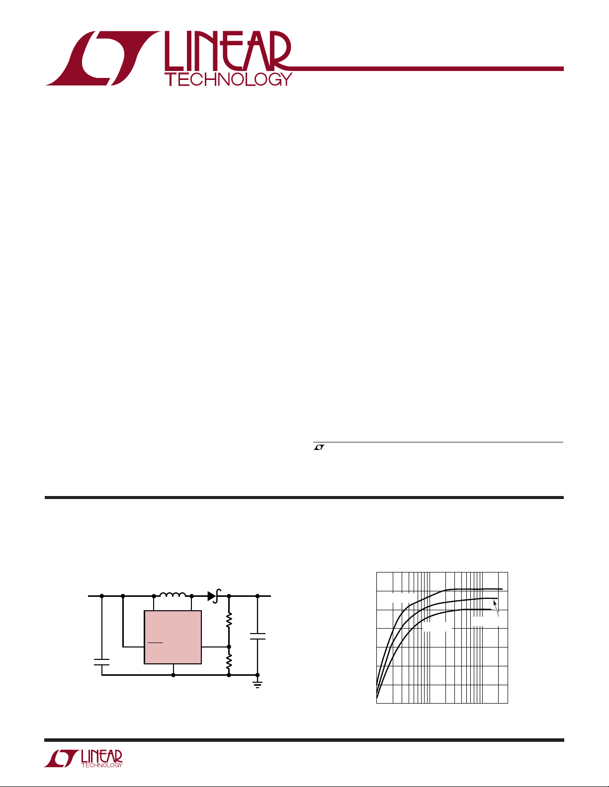
1-Cell Li-Ion to 20V Converter for LCD Bias
L1
V
IN
SHDN
10µH
LT1615
GND
V
2.5V TO 4.2V
IN
C1
4.7µF
C1: TAIYO YUDEN LMK316BJ475
C2: TAIYO YUDEN TMK316BJ105
D1: MOTOROLA MBR0530
L1: MURATA LQH3C100K24
SW
U
Efficiency
85
D1
R1
2M
FB
R2
130k
20V
12mA
C2
1µF
1615/-1 TA01
80
VIN = 4.2V
75
70
65
EFFICIENCY (%)
60
55
50
0.1 0.3
VIN = 2.5V
1 3 10 30
LOAD CURRENT (mA)
VIN = 3.3V
1615/-1 TA01a
1
LT1615/LT1615-1
WW
W
ABSOLUTE AXI U RATI GS
(Note 1)
U
UUW
PACKAGE/ORDER I FOR A TIO
ORDER PART
VIN, SHDN Voltage................................................... 15V
SW Voltage.............................................................. 36V
FB Voltage .................................................................V
IN
GND 2
Current into FB Pin ................................................. 1mA
Junction Temperature...........................................125°C
Operating Temperature Range (Note 2).. –40°C to 85°C
Storage Temperature Range................. –65°C to 150°C
Lead Temperature (Soldering, 10 sec)..................300°C
Consult factory for Industrial and Military grade parts.
ELECTRICAL CHARACTERISTICS
temperature range, otherwise specifications are at TA = 25°C. VIN = 1.2V, V
PARAMETER CONDITIONS MIN TYP MAX UNITS
Minimum Input Voltage LT1615-1 1.0 V
LT1615 1.2 V
Quiescent Current Not Switching 20 30 µA
= 0V 1 µA
V
SHDN
FB Comparator Trip Point ● 1.205 1.23 1.255 V
FB Comparator Hysteresis 8mV
Output Voltage Line Regulation 1.2V < VIN < 12V 0.05 0.1 %/V
FB Pin Bias Current (Note 3) VFB = 1.23V ● 30 80 nA
Switch Off Time VFB > 1V 400 ns
< 0.6V 1.5 µs
V
FB
Switch V
CESAT
Switch Current Limit LT1615-1 75 100 125 mA
SHDN Pin Current V
SHDN Input Voltage High 0.9 V
SHDN Input Voltage Low 0.25 V
Switch Leakage Current Switch Off, VSW = 5V 0.01 5 µA
I
= 70mA (LT1615-1) 85 120 mV
SW
I
= 300mA (LT1615) 250 350 mV
SW
LT1615 300 350 400 mA
= 1.2V 2 3 µA
SHDN
= 5V 8 12 µA
V
SHDN
The ● denotes the specifications which apply over the full operating
SHDN
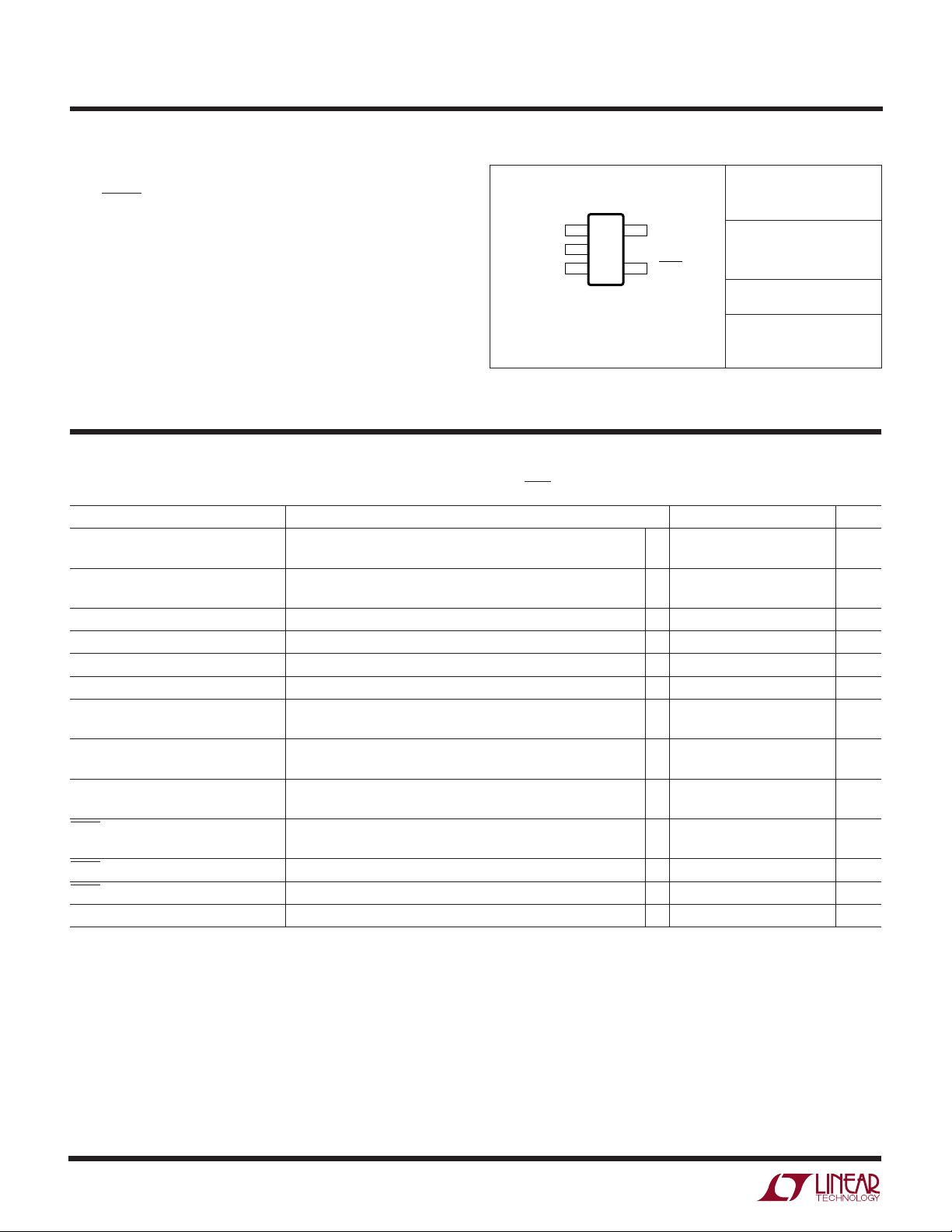
TOP VIEW
SW 1
FB 3
S5 PACKAGE
5-LEAD PLASTIC SOT-23
T
= 125°C, θJA = 256°C/W
JMAX
= 1.2V unless otherwise noted.
5 V
IN
4 SHDN
NUMBER
LT1615ES5
LT1615ES5-1
S5 PART MARKING
LTIZ
LTKH
Note 1: Absolute Maximum Ratings are those values beyond which the life
of a device may be impaired.
Note 2: The LT1615 and LT1615-1 are guaranteed to meet performance
specifications from 0°C to 70°C. Specifications over the
–40°C to 85°C operating temperature range are assured by design,
characterization and correlation with statistical process controls.
Note 3: Bias current flows into the FB pin.
2
UW
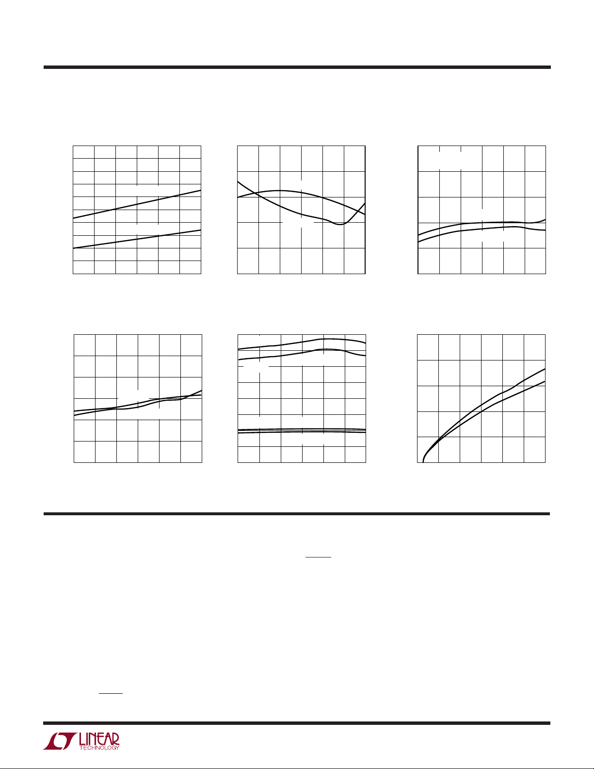
TYPICAL PERFOR A CE CHARACTERISTICS
LT1615/LT1615-1
Switch Saturation Voltage
(V
) Quiescent Current
CESAT
0.60
0.55
0.50
0.45
0.40
0.35
0.30
0.25
SWITCH VOLTAGE (V)
0.20
0.15
0.10
–25 0 25 50 75 100
–50
TEMPERATURE (°C)
I
SWITCH
I
SWITCH
= 500mA
= 300mA
1615/-1 G01
Feedback Pin Voltage and
Bias Current
1.25
1.24
1.23
1.22
FEEDBACK VOLTAGE (V)
1.21
1.20
–50
–25 0 25 50 75 100
Switch Off Time Shutdown Pin CurrentSwitch Current Limit
550
500
450
400
350
SWITCH OFF TIME (ns)
300
250
–50 –25 0 25 50 75 100
VIN = 1.2V
VIN = 12V
TEMPERATURE (°C)
1615/-1 G04
400
VIN = 12V
350
LT1615
300
250
200
150
LT1615-1
PEAK CURRENT (mA)
100
50
0
–50 –25 0 25 50 75 100
VOLTAGE
CURRENT
TEMPERATURE (°C)
VIN = 1.2V
VIN = 12V
VIN = 1.2V
TEMPERATURE (°C)
1615/-1 G02
1615/-1 G05
50
40
BIAS CURRENT (nA)
30
20
10
0
QUIESCENT CURRENT (µA)
SHUTDOWN PIN CURRENT (µA)
25
VFB = 1.23V
NOT SWITCHING
23
21
19
17
15
–50 –25 0 25 50 75 100
25
20
15
10
5
0
0 5 10 15
VIN = 12V
VIN = 1.2V
TEMPERATURE (°C)
1615/-1 G03
25°C
100°C
SHUTDOWN PIN VOLTAGE (V)
1615/-1 G03
UUU
PI FU CTIO S
SW (Pin 1): Switch Pin. This is the collector of the internal
NPN power switch. Minimize the metal trace area connected to this pin to minimize EMI.
GND (Pin 2): Ground. Tie this pin directly to the local
ground plane.
FB (Pin 3): Feedback Pin. Set the output voltage by
selecting values for R1 and R2 (see Figure 1):
RR
12
V
123
OUT
.
1=−
SHDN (Pin 4): Shutdown Pin. Tie this pin to 0.9V or higher
to enable the device. Tie below 0.25V to turn off the device.
VIN (Pin 5): Input Supply Pin. Bypass this pin with a
capacitor as close to the device as possible.
3
 Loading...