

Page 1
UC330-VC
CDMA Cellular
Communicator
Installation Instructions
1. PRODUCT DESCRIPTION
The UC330-VC CDMA Cellular Communicator functions as a phone line replacement for
alarm panel Central Station reporting. It replaces the traditional wired phone line servicing
the alarm panel with a device that communicates via cellular airwaves.
The communicator has an input to detect the alarm panel’s arming status and an output
to arm and disarm the alarm panel via the panel’s key switch input. The communicator is
powered and battery backed up directly from the alarm panel.
Seven indicators display setup information and status during operation. The cellular signal
strength is also displayed by the indicators.
A remote antenna with an 8 ft. lead is supplied with the UC330-VC Cellular Communicator.
It should be oriented and placed in a location that provides the best radio signal strength.
The unit also includes an optional tamper switch that, once installed, will notify the Central
Station if the communicator is tampered with or removed from its mounting location.
The communicator will need to be activated on-line before use. Refer to these instructions
and the on-line LinearLinc/nuLinc Dealer setup information on the LinearLinc Web site.
To setup the nuLinc remote arm/disarm and system arming status connections, the
alarm panel’s armed output polarity and key switch input polarity and type will need to be
programmed in the panel. Refer to the alarm panel’s instructions and the on-line UC330-VC
Alarm Panel Connections & Programming Technical Bulletin (TB2013-004) for details.
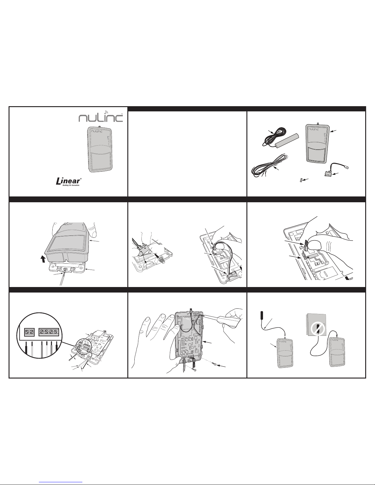
2. MODULE COMPONENTS
3. ON-LINE ACTIVATION / REMOVING COVER
Log onto http://www.linearlinc.com to setup a Dealer account and activate the
device. This should be done prior to installing the UC330-VC at the customer location.
Open UC330-VC enclosure by loosening screw on enclosure chassis and lifting up on the
enclosure top.
4. INSTALLING AND WIRING TAMPER ALARM SWITCH
If a Tamper Alarm is required, install Tamper Switch (included) into the enclosure chassis
bracket as shown. Be sure that the tamper switch “snaps” into the bracket pins face down
and pivots freely. After installing Tamper Switch into enclosure chassis, plug the tamper plug
into the Tamper Header. The location is shown with a label and arrow on the circuit board.
5. WIRING TERMINATION (IF NOT USING TAMPER SWITCH)
If a Tamper Switch is not required, plug the Jumper (provided) in place on the Tamper
Header pins to prevent the tamper alarm from being raised.
6. CHASSIS TERMINAL BLOCK WIRING
Using the color coded connector wires (provided) insert into screw terminals on UC330-VC
enclosure chassis as shown in diagram. Feed wires through wiring guides located at the
bottom edge of the chassis. NOTE: Install in accordance with the National Electrical Code,
ANSI/NFPA 70.
7. MOUNTING ENCLOSURE CHASSIS
Determine location for UC330-VC enclosure chassis and install using 4 mounting screws
(provided). NOTE: Install in the same room and up to 3 feet away from alarm panel.
8. ANTENNA INSTALLATION
Fasten remote antenna to top of UC330-VC enclosure. Remove backing from sticky tape
on antenna. Place antenna at an optimal location that maximizes signal strength, usually
highest point above enclosure. Refer to Figure 12 for signal strength indicators. Be sure to
keep antenna away from any metal objects to prevent interference.
USA & Canada (800) 421-1587 & (800) 392-0123
(760) 438-7000 - Toll Free FAX (800) 468-1340
www.linearcorp.com
POWER
LINK
ACTIVITY
SIGNAL
STRENGTH
ENCLOSURE
CHASSIS
(TOP REMOVED)
TO ALARM PANEL
TO 12V AUX. OUTPUT (RED)
TO GROUND (BLACK)
BLUE
WHITE
SCREW
TERMINAL WIRE
LOCATIONS
PNL
PSTN
R Y G B
WIRING
GUIDE
BLUE
WHITE
RED
BLK.
YEL.
GRN.
TO KEYSWITCH ARM/DISARM (YELLOW)
TO ARM STATUS (GREEN)
TAMPER SWITCH
SNAP TAMPER SWITCH
INTO CHASSIS BRACKET PINS
WITH SWITCH ARM FACING
DOWN
SWITCH
ARM
TAMPER
TAMPER
HEADER
TAMPER SWITCH
INSTALLED
IN CHASSIS
TAMPER PLUG
TAMPER
JUMPER
TAMPER HEADER
ENCLOSURE TOP
ENCLOSURE
CHASSIS
LOOSEN SCREW, THEN
PULL UP TO REMOVE
CASE
POWER
LINK
ACTIVITY
SIGNAL
STRENGTH
ENCLOSURE
CHASSIS
MOUNTING
SCREWS
UC330-VC
CDMA CELLULAR
COMMUNICATOR
ANTENNA
COLOR CODED
WIRE
TAMPER SWITCH
JUMPER
POWER
LINK
ACTIVITY
SIGNAL
STRENGTH
DO NOT MOUNT
REMOTE ANTENNA
ON A METAL BOX 0R
DOOR FRAME
MOUNT ANTENNA
AT LEAST
4” AWAY FROM
UC330-VC UNIT
NO!
REMOTE ANTENNA
UC330-VC
POWER
LINK
ACTIVITY
SIGNAL
STRENGTH
POWER
LINK
ACTIVITY
SIGNAL
STRENGTH
Page 2
Copyright © 2013 Linear Corporation P1807 X4
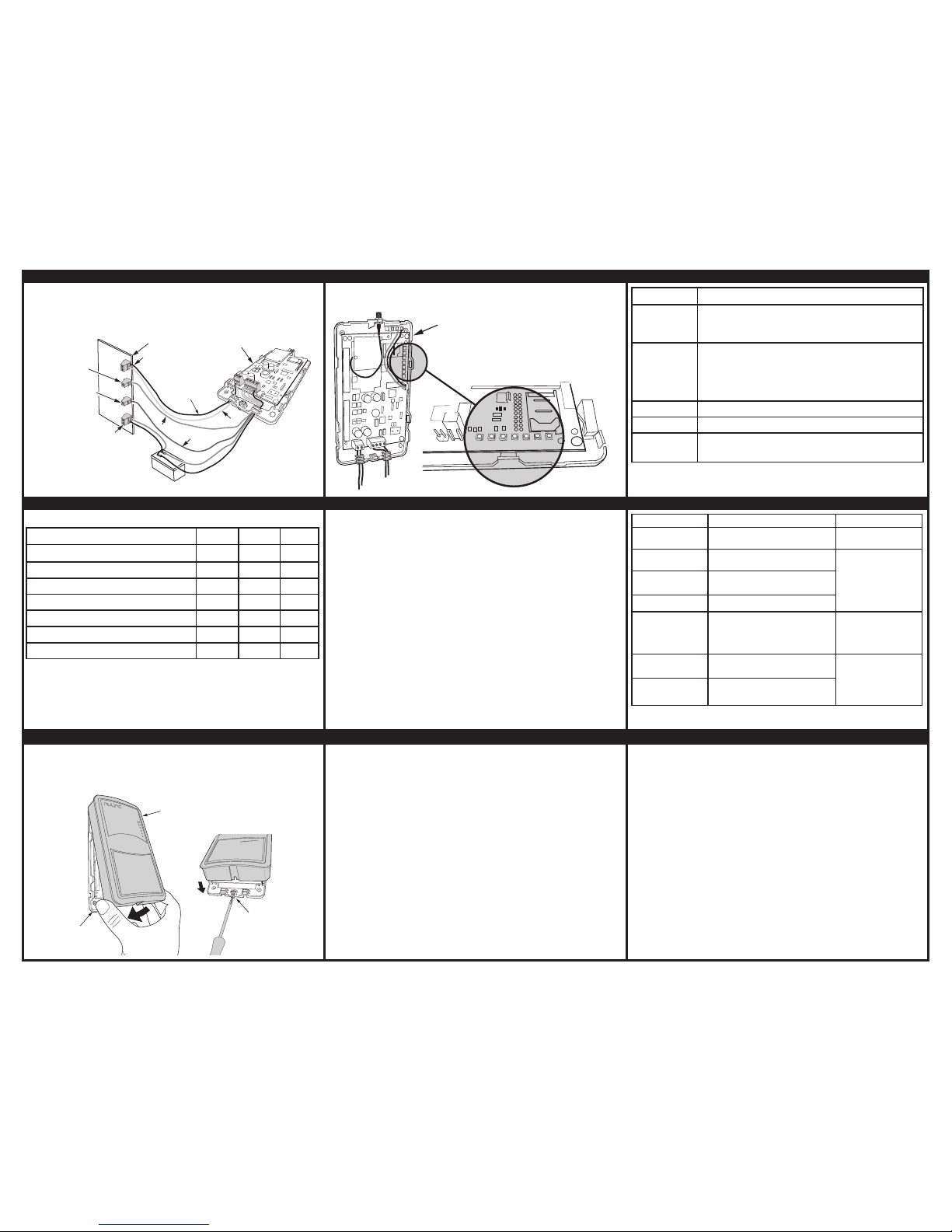
9. WIRING UC330-VC TO ALARM PANEL
Power down the alarm panel and disconnect battery. Connect the UC330-VC to the alarm
panel’s 12VDC auxiliary output, telco ring and tip, key switch arm/disarm, and armed status
terminals using the color coded wires (provided). After connecting all appropriate wires and
battery, turn on power to the alarm panel.
10. LED STATUS INDICATORS
The UC330-VC has indicators which display unit status. They are located on the upper right
edge of the circuit board See chart in following box for unit status descriptions.
11. UNIT LED INDICATOR STATUS DESCRIPTION
INDICATOR DESCRIPTION
STATUS
OFF - the unit is not powered
FLASHING - the unit is booting
SOLID - the unit is powered and ready
CELL IP
OFF - the unit does not have IP connectivity over cellular network
SLOW FLASHING - the unit has an IP address but is not connected to
a LinearLinc server
SOLID - the unit has established a secure communications session
with a LinearLinc server
AUDIO ACT
SOLID - alarm panel communicating
SS1, SS2, SS3
Wireless signal strength indicators. Refer to next table
BUS
Not used
15. FINAL INSTALLATION
To close the UC330-VC unit, place the top over the base at the antenna end, then lower the
lid until it sits fl ush with the base. Finally, insert and tighten the locking screw at the base
of the enclosure chassis. Observe warning regarding mounting of remote antenna location.
16. SYSTEM TESTING
Before leaving site, complete the following installation checks:
1. UC330-VC mounted in tamper-proof enclosure.
2. UC330-VC powered from battery-backed power system and power budget has been
checked (UC330-VC draws average of 50mA, peak of 230mA).
3. Wireless signal strength is acceptable range or better
4. UC330-VC communicating with central station (Cell IP solid)
5. Alarms have been generated from the alarm panel and correct reception has been
confi rmed at the central station.
This equipment should be installed in accordance with Chapter 2 of the National Fire Alarm
Code, ANSI/NFPA 72. (National Fire Protection Association, Batterymarch Park, Quincy,
MA 02269)
LINEAR LIMITED WARRANTY
This Linear product is warranted against defects in material and workmanship for twelve (12) months. This warranty
extends only to wholesale customers who buy direct from Linear or through Linear’s normal distribution channels. Linear
does not warrant this product to consumers. Consumers should inquire from their selling dealer as to the nature of the
dealer’s warranty, if any. There are no obligations or liabilities on the part of Linear Corporation for consequential
damages arising out of or in connection with use or performance of this product or other indirect damages with
respect to loss of property, revenue, or profi t, or cost of removal, installation, or reinstallation. All implied warranties,
including implied warranties for merchantability and implied warranties for fi tness, are valid only until Warranty Expiration
Date as labeled on the product. This Linear LLC Warranty is in lieu of all other warranties express or implied.
All products returned for warranty service require a Return Product Authorization Number (RPA#). Contact Linear Technical
Services at 1-800-421-1587 for an RPA# and other important details.
IMPORTANT !!!
Linear radio controls provide a reliable communications link and fi ll an important need in portable wireless signaling.
However, there are some limitations which must be observed.
• For U.S. installations only: The radios are required to comply with FCC Rules and Regulations as Part 15 devices. As such,
they have limited transmitter power and therefore limited range.
• A receiver cannot respond to more than one transmitted signal at a time and may be blocked by radio signals that occur on
or near their operating frequencies, regardless of code settings.
• Changes or modifi cations to the device may void FCC compliance.
• Infrequently used radio links should be tested regularly to protect against undetected interference or fault.
• A general knowledge of radio and its vagaries should be gained prior to acting as a wholesale distributor or dealer, and
these facts should be communicated to the ultimate users.
This device complies with Industry Canada license-exempt RSS standard(s). Operation is subject to the following
two conditions: (1) this device may not cause interference, and (2) this device must accept any interference, including
interference that may cause undesired operation of the device.
Le présent appareil est conforme aux CNR d’Industrie Canada applicables aux appareils radio exempts de licence.
L’exploitation est autorisée aux deux conditions suivantes: (1) l’appareil ne doit pas produire de brouillage,et (2) l’utilisateur
de l’appareil doit accepter tout brouillage radioélectrique subi, même si le brouillage est susceptible d’en compromettre le
fonctionnement.
12. WIRELESS SIGNAL STRENGTH
The SS1, SS2, and SS3 LEDs indicate wireless signal strength as shown below.
*
SIGNAL STRENGTH
SS1 SS2 SS3
No reading available (eg modem is being reset)
OFF OFF OFF
Attempting to register on network
FLASH OFF OFF
<-89DbM Unacceptable
ON OFF OFF
-89dBm to -83dBm Poor
ON FLASH OFF
-83dBm to -77dBm Good
ON ON OFF
-77dBm to -70dBm Very Good
ON ON FLASH
>-70dBm Excellent
ON ON ON
13. COMMUNICATOR ACTIVATION AND START-UP
NOTE: The unit must be activated prior to testing and use. After activating UC330-VC, the
expected start-up sequence is as follows:
1. Power indicator fl ashes for 10 seconds then comes on solid
2. Within 30 seconds, the CELL IP indicator should start to fl ash slowly
3. Within 60 seconds, the CELL IP indicator should go solid. This may take up to fi fteen
minutes in poor reception areas.
4. If this is the initial power on or power on after a fi rmware upgrade, the unit will receive
its confi guration and may reboot.
5. Steps 1-3 above will then occur again
Once activated and connected, the normal Indicator status is
• Status Indicator: Solid
• Cell IP: Solid
• SS1, SS2, SS3: wireless signal strength
If this is not observed, consult the table in Step 14.
14. TROUBLESHOOTING GUIDE
CONDITION CAUSE ACTION
POWER LED OFF
Inadequate power supplied to
UC330-VC
Check 12VDC @ 230mA
is available.
CELL IP LED OFF
No network coverage, SIM not activated
or wireless authentication failed.
Call Technical Services
CELL IP LED
FLASHING
Network connectivity good, but account
is not activated in LinearLinc server.
SS1 FLASHING
The SIM card has not been activated
SS2 OFF
The signal for wireless communications
is too low
Move antenna until SS2 is
fl ashing or solid. A higher
gain antenna may be
needed.
SS2 SOLID or
FLASHING
Acceptable wireless signal strength
No action needs to be
taken.
SS3 SOLID or
FLASHING
Excellent wireless signal strength
UC330-VC
ENCLOSURE
TOP
UC330-VC
ENCLOSURE
CHASSIS
TIGHTEN SCREW
SNAP TOP ENCLOSURE
DOWN ON ENCLOSURE
CHASSIS
POWER
LINK
ACTIVITY
SIGNAL
STRENGTH
*
Unit is a global CDMA communicator that will locate the strongest cellular
signal regardless of carrier and will periodically scan and automatically change
to a stronger cellular carrier signal.
SPECIFICATIONS:
Voltage: 10VDC to 18VDC
Current: (@10V) 50mA average, 230mA peak
(@12V) 45mA average, 180mA peak
Environmental Conditions: -10 to +70 degrees C
5% to 90% relative humidity non-condensing
Panel Interface: Dial Capture
Wireless Interface: CDMA network compatible
UC330-VC
ENCLOSURE
CHASSIS
STATUS
CELL
IP
AUDIO
ACT
SS1
SS2
SS3 BUS
INDICATOR LOCATION
ON CIRCUIT BOARD FOR DIAGNOSTICS
ALARM PANEL
RING
TIP
TO TELCO
BATTERY
TERMINALS
ENCLOSURE
CHASSIS
+
−
RED
BLACK
(BLUE)
(WHITE)
ZONE PROGRAM
FOR KEYSWITCH
ARM/DISARM
(YELLOW)
(GREEN)
ARMED STATUS
REFER TO ALARM PANEL MANUAL INSTRUCTIONS FOR PROGRAMMING & WIRING
12V BATTERY
 Loading...