

Page 1
TM D-9 0
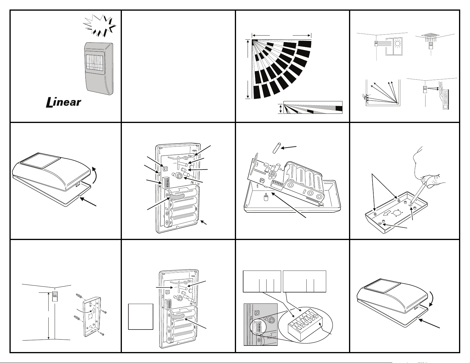
TOP VIEW
SIDE VIEW
7.5'
(2.29 M)
AB
CD
D
C
B
A
40' (12.19 M)
40' (12.19 M)
A = CREEP ZONES
B = SHORT RANGE ZONES
C = INTERMEDIATE ZONES
D = MAIN ZONES
DETECTION
PATTERN
LOCKING TAB
WILL SNAP SHUT
CLOSE
CASE
SUPERVISED WIRELESS
PASSIVE INFRARED
MOTION DETECTOR
Installation Instructions
(760) 438-7000 • FAX (760) 438-7043
USA & Canada (800) 421-1587 & (800) 392-0123
Toll Free FAX (800) 468-1340
SX
FORMAT!
DESCRIPTION The TMD-90 is a passive infrared (PIR)
motion detector with a built-in supervised, digitally-coded radio
transmitter designed for security applications.
The PIR detects motion in its detection pattern by measuring the
infrared emission levels of objects that it “sees”. If the infrared levels
change quickly, as when a person moves across the detection
pattern, the PIR will recognize the change as an intrusion.
A selectable “pulse count” circuit controls the PIR’s triggering of the
transmitter. As a person moves across the detection pattern, the PIR
registers one pulse as each “finger” of the detection pattern is
crossed. The TMD-90 counts these pulses. When the selected
number of pulses occur during the selected time, the PIR will trigger
the transmitter, sending an alarm signal. A lockout timer prevents the
transmitter from triggering more often than once every 2 minutes
when constant motion is detected. The pulse counting and timing
options are selected with the OPTION switch.
The unit is supervised for low battery, alarm and status reporting. The
TMD-90 is compatible with any Linear SX format supervised
security receiver. The transmitter sends hourly status reports. A test
report can be sent by pressing the test button.
Coding switches are not required or used in this transmitter. Each
transmitter is pre-coded at the factory to a unique code. With the SX
format, there are more than sixteen million codes possible.
The transmitter is powered by four Duracell “AA” MN1500 1.5-volt
alkaline batteries (included) and can power the unit for up to 5 years.
When the battery voltage gets low, a low battery report is sent to the
receiver with any alarm, test or status report.
DON'T ALLOW
DIRECT SUNLIGHT
HEAT
&
COLD
WINDOW
DON'T AIM
AT GLASS
INSTALLATION TIPS
DON'T MOUNT
NEAR VENT
DON'T AIM
AT HEATER
STEP 1 Open detector case. Press in the locking tab and
remove the case cover.
PUSH IN
LOCKING TAB
STEP 5 Mount case. Attach the case to the wall using the
screws and screw anchors provided. Mount the detector in a
location where the intruder’s path will likely cross the
detection pattern beams.
USE SCREWS AND
ANCHORS TO MOUNT
CASE TO WALL
APPROXIMATELY
7 FEET FROM FLOOR
ARROW ON
CASE POINTS
TO TOP
OPEN
CASE
STEP 2 Identify components. Examine the unit to identify
the various components.
TRANSMITTER
TEST BUTTON
TAMPER
SWITCH
OPTION
SWITCH
BATTERY
PROTECTION
STRIP
ANTENNA
ADJUSTMENT
POST
WALK TEST
LED
INFRARED
DETECTOR
FOUR TYPE "AA"
BATTERIES
STEP 6 Replace board. Replace the circuit board and
install the adjustment post. Center the detection pattern pointer.
Remove the battery protection strip.
REPLACE
CENTER DETECTION
PATTERN POINTER
ON ADJUSTMENT
POST
NOTE:
USE DURACELL
MN1500 OR
TOSHIBA LR6G
"AA" ALKALINE
BATTERIES
ONLY!
ADJUSTMENT
POST
REMOVE THE
BATTERY
PROTECTION
STRIP
STEP 3 Remove circuit board. Remove the adjustment
post and remove the circuit board.
REMOVE
ADJUSTMENT
POST
SLIDE CIRCUIT
BOARD UP
TO REMOVE
STEP 7 Set option switches. Set the option switches to
select the number of pulses and time frame for alarm. Set
switches 2 & 5 ON, 1, 3 & 4 OFF. Set switch #6 ON to select
walk test mode.
SWITCHES 1, 2 & 3
SET NUMBER OF PULSES
#1 #2 #3
2 PULSES
3 PULSES
5 PULSES
ON
OFF
OFF
OFF
ON
OFF
SWITCHES 4 & 5 SET TIME
THAT PULSES MUST OCCUR
8 SECONDS
OFF
16 SECONDS
OFF
32 SECONDS
OFF
OPTION SWITCH
#4 #5
ON
OFF
OFF
OFF
ON
OFF
#6 ON FOR
WALK TEST
SET
SWITCH
STEP 4 Punch out knockouts. Use a small Phillips
screwdriver to punch out the desired case mounting knockouts.
PUNCH OUT
SIDE KNOCKOUTS
FOR CORNER MOUNTING
LAY BASE ON
CARPET AND
PUNCH OUT
KNOCKOUTS
WITH PHILLIPS
SCREWDRIVER
PUNCH OUT
BACK KNOCKOUTS
FOR WALL MOUNTING
STEP 8 Replace cover. Replace the case cover. Press the
bottom edge until the locking tab engages.
Page 2
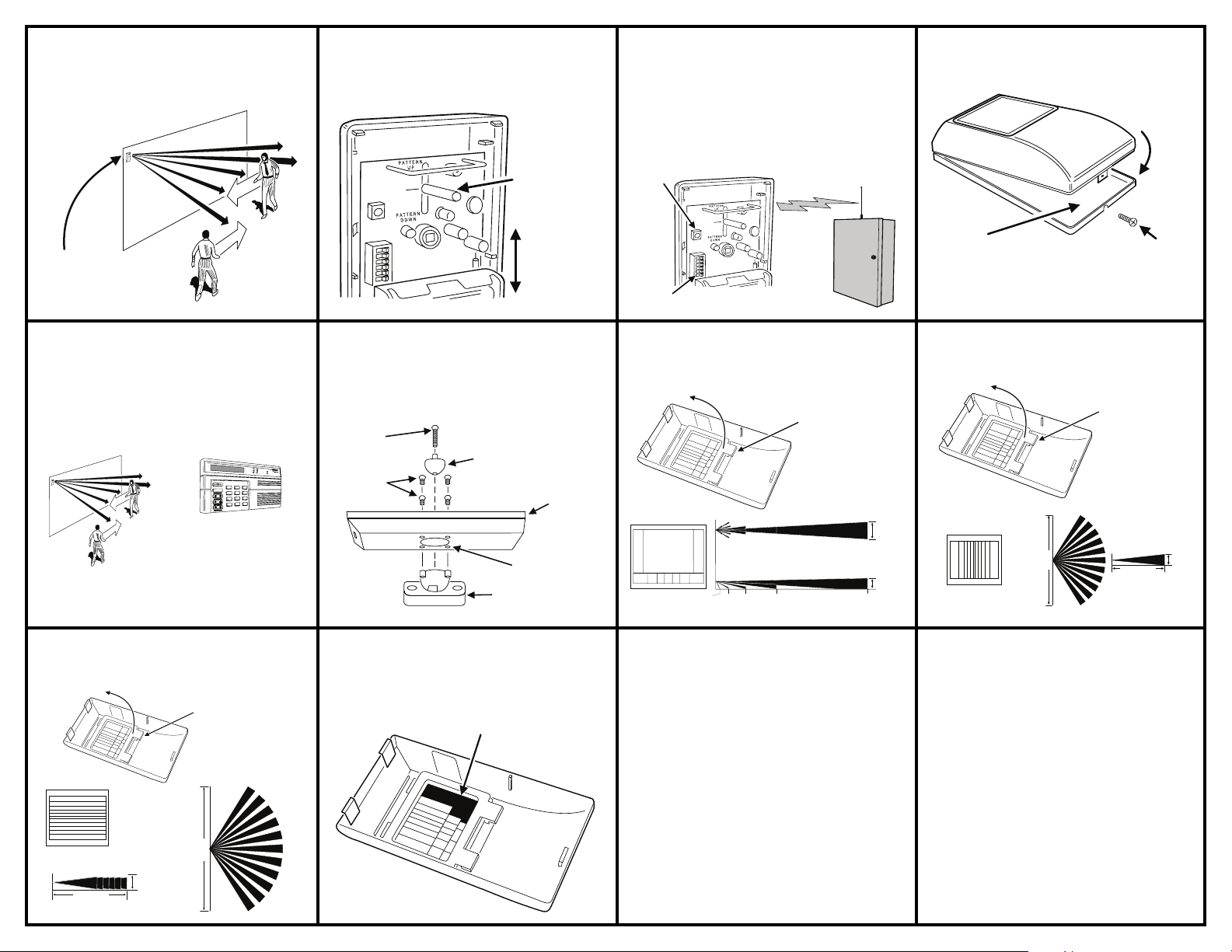
STEP 9 Walk test. Walk test the unit by walking across the
PRESS TEST
BUTTON
TO SEND
SIGNAL
SWITCH #6
MUST BE
OFF
RECEIVER
LEARNS
TRANSMITTER
ID CODE
LOCKING TAB
WILL SNAP SHUT
CLOSE
CASE
INSERT LOCKING
SCREW
PRY TABS UP TO
REMOVE LENS
BRACKET
INSERT NEW LENS
WITH SMOOTH SIDE
OUT
6.56'
(2 m)
13.12'
(4 m)
26.24'
(8 m)
52.48'
(16 m)
10.5'
(3.2 m)
14.43'
(4.4 m)
TOP VIEW
SIDE VIEW
131.2'
(40 m)
LONG RANGE LENS
detection pattern from both sides. The red LED should light as you
cross each detection pattern “finger”. (Alarm transmissions will
occur in walk test.)
WALK ACROSS
DETECTION PATTERN
WATCH RED LED AS
DETECTOR SENSES
MOTION
STEP 10 Adjust detection pattern. If the detection
pattern is too high or low, loosen the adjustment post and slide
the circuit board up or down.
LOOSEN
ADJUSTMENT
POST TO SLIDE
BOARD
SLIDE BOARD
UP OR DOWN
TO ADJUST
PATTERN
NOTE: BOARD UP
ADJUSTS
PATTERN DOWN
STEP 11 Program transmitter into receiver. Refer to the
instructions supplied with the supervised receiver to program the
TMD-90 as a non-restoring PIR sensor. Turn the walk test switch
(#6) OFF. Press the TEST button to cause the unit to send a
signal. The TEST button will not send a valid signal if the unit
is in walk test (switch #6 ON).
STEP 12 Replace and lock cover. Replace the unit’s
cover and secure it with the locking screw.
STEP 13 System test. Place the receiver into a sensor test
mode. Stay out of the detection pattern of the PIR for at least
4 minutes then walk across the detection pattern. The receiver
should indicate that the signal was received.
WAIT AT LEAST 4 MINUTES BEFORE
WALKING ACROSS THE DETECTION PATTERN!
1
?
?
?
4
7
*
SYSTEM IN TEST MODE
SHOULD BEEP AS ALARM
SIGNAL IS RECEIVED
AFTER WAITING, WALK
ACROSS DETECTION
PATTERN
Optional Vertical Curtain Lens See the figure for
details on changing lenses.
PRY TABS UP TO
CURTAIN LENS
VERTICAL
TOP VIEW
(12.19 m)
4.4'
(1.34 m)
40'
REMOVE LENS
BRACKET
INSERT NEW LENS
WITH SMOOTH SIDE
OUT
SIDE
VIEW
80'
(24.38 m)
Optional Swivel Mount An optional swivel mount is
supplied for mounting the TMD-90 to a wall in special situations.
Refer to the figure for details on attaching the swivel mount to the
Optional Long Range Lens See the figure for
changing supplied lenses. Do not set the pulse count for more
than 2 pulses when using the long range lens.
Optional Horizontal Curtain Lens See the figure for
changing supplied lenses.
case (swivel mount must be assembled first).
PRY TABS UP TO
REMOVE LENS
LONG
A
l
a
r
m
L
o
w
B
a
t
e
t
r
y
O
p
e
n
S
u
p
e
r
i
v
s
o
r
y
T
r
B
o
p
y
u
a
s
b
l
s
e
T
a
m
p
e
r
P
o
w
e
r
2
3
6
5
9
8
#
0
SHORT
SCREWS (4)
Optional Lens Masks Adhesive stick-on labels are
provided to mask unwanted detection areas of each lens. Apply
the labels to the inside of the lens.
SCREW (1)
SWIVEL
BALL
BASE
PUNCH OUT
KNOCKOUTS
SWIVEL
BASE
APPLY LENS MASKING
STICKERS TO THE INSIDE
OF THE LENS
SPECIFICATIONS
OPERATING TEMPERATURE:
DETECTOR: Balanced dual-element pyro electric
LENS: Aspheric fresnel lens with 24 facets,
DETECTION PATTERN: 40 x 40 feet (12.2 x 12.2 M)
VERTICAL ADJUST: Installer adjustable up and down
SIGNAL PROCESSING: Selectable pulse count (2, 3 & 5 pulses)
POWER REQUIREMENTS: Four type “AA” MN1500 batteries
RF ENCODING: Linear SX format (A1D PPM @ 200 bps)
NUMBER OF CODES: 16,777,216
TAMPER SWITCH: Switch linked to case cover
DIMENSIONS: 5.75" high x 3.25" wide x 1.75" deep
9 main, 8 intermediate, 5 short, 2 creep
Pulse window (8, 16 & 32 seconds)
Operating:12 mA maximum
Standby: 15 uA maximum
LED: Extra bright for walk test
SHIELDING: Metal shielding for maximum RFI/EMI immunity
+32° to +122° F
(0° to +50° C)
COLOR: Cool Gray 1C
MOUNTING: Wall, corner or swivel
HORIZONTAL
CURTAIN LENS
80'
(24.38 m)
LINEAR LIMITED WARRANTY
This Linear product is warranted against defects in material and workmanship for twelve (12) months. The
Warranty Expiration Date is labeled on the product. This warranty extends only to wholesale customers
who buy direct from Linear or through Linear’s normal distribution channels. Linear does not warrant
this product to consumers. Consumers should inquire from their selling dealer as to the nature of the
dealer’s warranty, if any. There are no obligations or liabilities on the part of Linear LLC f or
consequential damages arising out of or in connection with use or performance of this product
or other indirect damages with respect to loss of property, revenue, or profit , or cost of removal,
installation, or reinstallation. All implied warranties, including implied warranties for merchantability and
implied warranties for fitness, are valid only until Warranty Expiration Date as labeled on the product. This
Linear LLC Warranty is in lieu of all other warranties express or im plied.
All products returned for warranty service require a Return Product Authorization Number (RPA#). Contact
Linear Technical Services at 1-800-421-1587 for an RPA# and other important details.
Linear radio controls provide a reliable communications link and fill an important need in portable wireless
signalling. However, there are some limitations which must be observed.
1 For U.S. installations only: The radios are required to comply with FCC Rules
and Regulations as Part 15 devices. As such, they have limited transmitter
power and therefore limited range.
1 A receiver cannot respond to more than one transmitted signal at a time and
may be blocked by radio signals that occur on or near their operating
frequencies, regardless of code settings.
1 Changes or modifications to the device may void FCC compliance.
1 Infrequently used radio links should be tested regularly to protect against
undetected interference or fault.
1 A general knowledge of radio and its vagaries should be gained prior to acting
as a wholesale distributor or dealer, and these facts should be communicated
to the ultimate users.
Copyright © 2006 Linear LLC 208457 E
BRACKET
INSERT NEW LENS
WITH SMOOTH SIDE
OUT
TOP
VIEW
40'
(12.19 m)
(.91 m)
SIDE VIEW
3'
 Loading...