

Page 1
Features:
• Vandal Resistant Case
• Sealed For Indoor or Outdoor Applications
• LED’s For Relay Status Indication
• Bell Output
• Surface mount
• Illuminated hardened keys
• Rated at greater than one million key cycles
Applications:
• Low-Medium/Heavy Traffic Use
• Rough Service Environments
• Mullion Frame Mounting
For use with the following:
• Most Wiegand electronic access control panels.
• Any IEI Secured Series door control module (DCM).
• IEI Stand Alone Access Control.
Functionality:
Combining elegant looks and mullion mount design in a
rugged vandal resistant case, IEI’s new Door-Gard
Series Mullion keypad can be utilized for most any
application. Designed to perform in medium-high traffic
and rough duty environments, the IEI Door-Gard Series
Mullion has hardened backlit keys. Encapsulated electronics makes the Door-Gard Series Mullion keypad
suitable for indoor or outdoor installations . The keypad
is activated by entering any 1-6 digit programmed code
followed by the star * key. IEI offers the Door-Gard
Series Mullion keypad as model SSW-iLM, a keypad
only version for use with an IEI controller or in Wiegand
applications.
Wire Requirements:
Maximum distance with stranded shielded :
18 AWG - 1000’
20 AWG - 500’
22 AWG - 250’
Packing List: (SSW-iLM)
IEI Door-Gard Mullion keypad (1)
Eight conductor wire harness (1)
8 x 1 1/4” Panhead Machine screws (2)
8 x 1 1/4” Panhead wood/sheet metal screws (2)
5/64” Allen wrench (1)
Anti Oxidant Grease (1)
Instruction manual w/template (1)
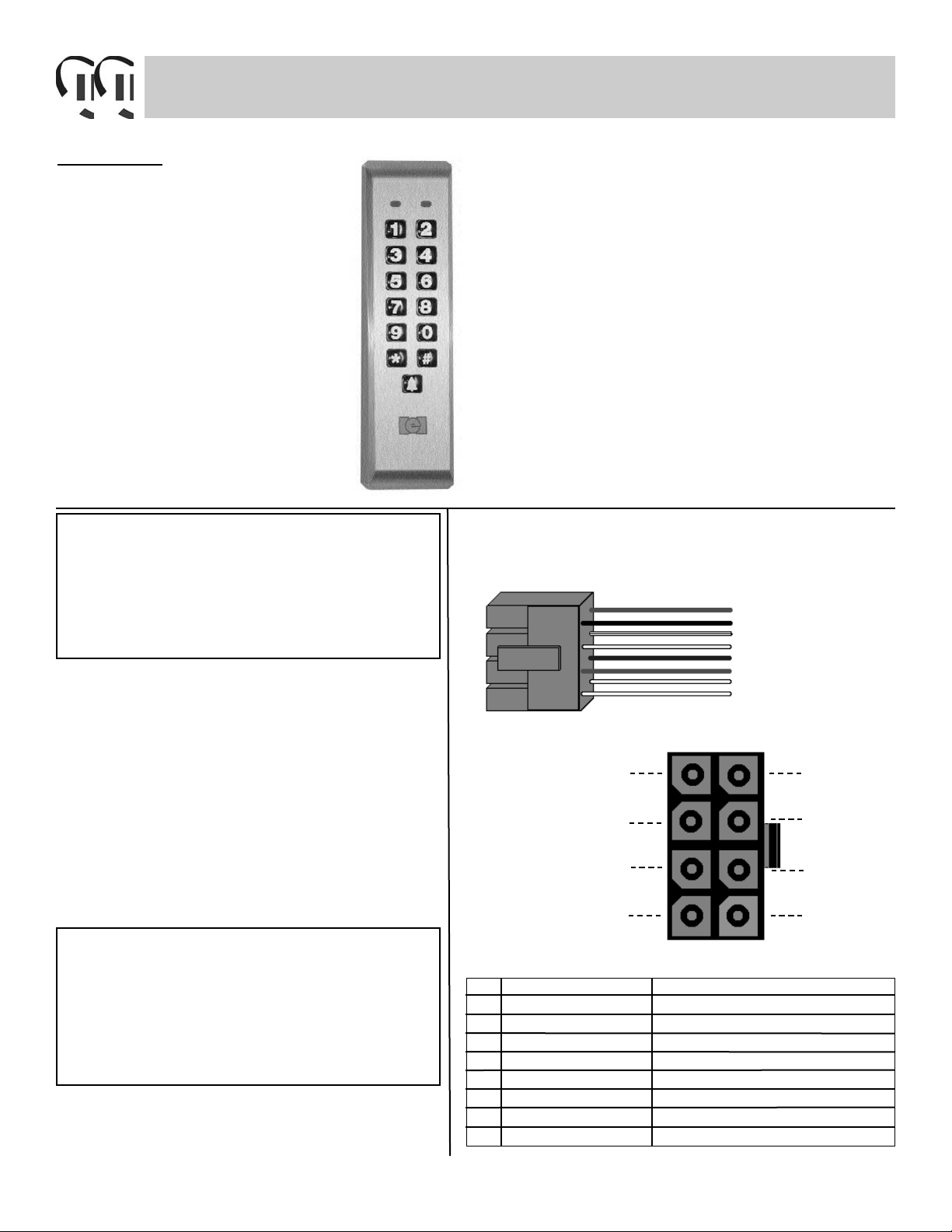
SSW-iLM Keypad
Wire Harness Configuration
1
3
5
7
2
4
6
8
Pin Wire color Signal name
1 Red V in (+)
2 Black V in (-)
3 White/Black Data 0
4 White/Yellow Data 1
5 Blue LED 1
6 Brown LED 2 (not used)
7 White Bell Relay Contact (A)
8 White Bell Relay Contact (B)
605 5161 Rev. 1.21 of 8
S
pecifications
Case dimensions:
6 1/2”L x 1 3/4” W x 1 1/8”D
Electrical:
5-12VDC Only
Current draw:
5VDC: 28mA typical; 60mA max
12VDC: 27mA typical; 77mA max
Bell relay: (form A)
1amp @ 30VDC
500ma @ 125VAC
Environmental:
-20º F to 130º F
Note: This product is designed to be installed and serviced by security and lock industry professionals
Page 2
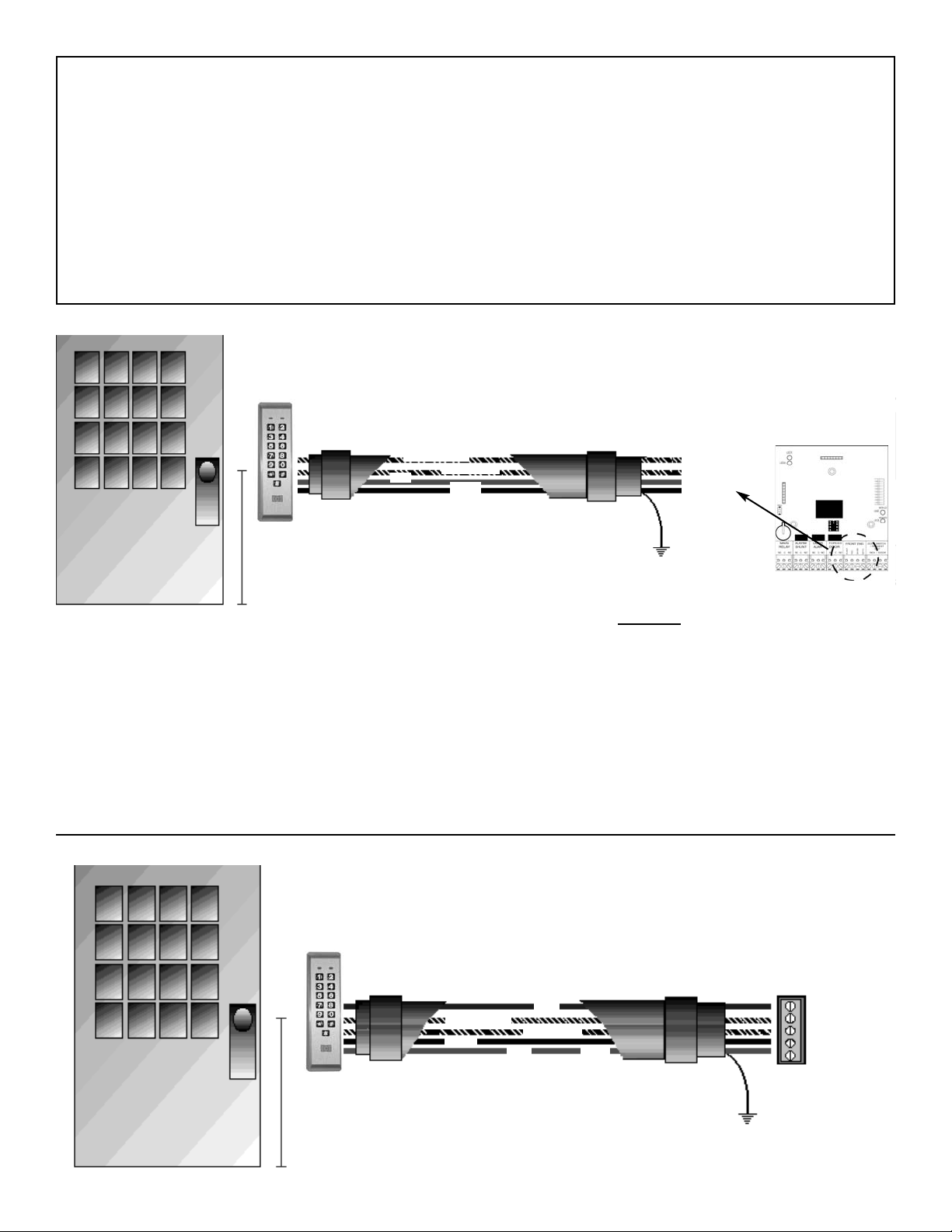
Wiring the Door-Gard Mullion Keypadto an IEI Hub DCM
Wiring the SSW-iLM to an IEI Hub DCM requires a four conductor, stranded and shielded cable to be wired between
the two units. Maximum lengths are as follows:
The drain wire from the wire run must be attached to ground. Ground is the FT1 tab loacted on the HubMax/Minimax
backplane. At the mullion keypad, the drain wire and foil shield should be cut back with the insulator and taped with electrical tape. The eight conductor harness connects into the eight pin connector on the SSW-iLM keypad. You may use
two keypads to one Hub DCM for in/out operation. Parallel both readers on the same wire run from the Hub
DCM.
Note: If two keypads are desired the extra keypad # is SSW-iLM.
22 AWG stranded : 250 feet
20 AWG stranded : 500 feet
18 AWG stranded : 1000 feet
Electrical
Tape
Electrical
Tape
Keypad
Insulator
BLACK
RED
BLACK/WHITE
WHITE\YELLOW
Ò
Ò
Ò
Ð
Drain
Wire
Î
48”
Wiring the Door-Gard Series Mullion Keypad to a Wiegand Panel
Electrical
Tape
Electrical
Tape
Keypad
Insulator
BLACK
RED
BLACK/WHITE
WHITE/YELLOW
Ò
Ò
Ò
Ð
Drain
Wire
Î
48”
Blue
+ 5-12 VDC
- GND
DATA 0
DATA 1
LED 1
To Install:
Step 1: • Drill through the back plate using a 11/64” bit. Use the template provided to accurately mark
the holes needed for mounting. Drill the mounting holes with a 9/64” drill bit, also drill the hole
for the wire run (size determined by number of wires used).
Step 2: • Be sure to strip back the insulator from the wire run, and tape the shield to the jacket.
• Connect the eight conductor harness supplied with the SSW-iLM keypad to the five
conductor wire run for Wiegand connection or four conductor for an IEI Hub DCM as shown in
the diagrams below.
• Apply Anti Oxidant grease (supplied) to the keypad connector.
Step 3: • Place the Door-Gard Series Keypad on the wall or back box, and secure with the provided
screws. DO NOT OVER TIGHTEN. (Damage may occur)
* Brown & Blue wires are not used when using an IEI controller
Brown wire not used
605 5161 Rev. 1.2
2 of 8
The following connections are
to be made at the “Front End”
connection on the Hub DCM.
WHITE\YELLOW
WHITE\BLACK
RED
BLACK
Hub DMC
Page 3
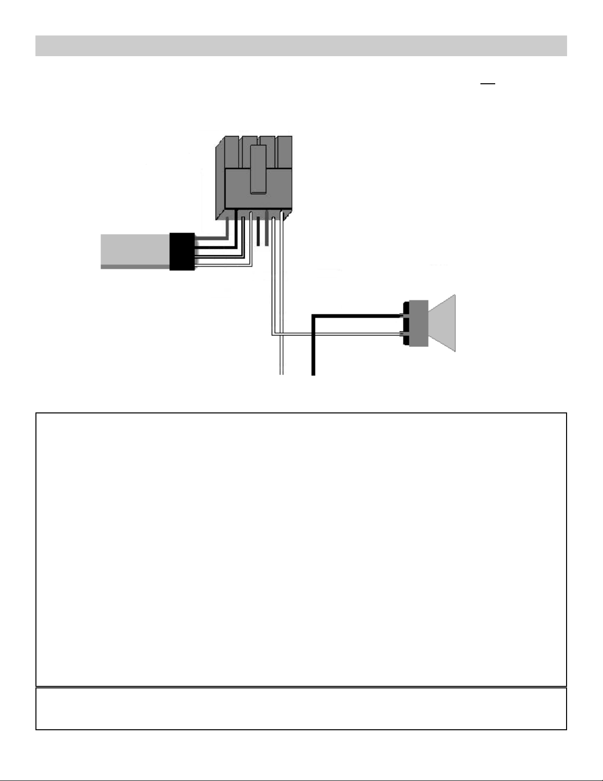
Wiring the bell output to a speaker
With the SSW-iLM you can use the bell button to trigger an external device such as a door bell or like devices
that require a momentary closer to operate. This is easily accomplished by either using the dry
contact provided or you can run up to 24VDC or 120VAC through one leg of the bell output (A) and connecting the other
leg (B) to the power in on your device. Then connect the negative connection on your device to the negative
on your power supply (as shown below).
SSW-iLM
wire harness
To IEI controller
Speaker
Positive
Negative
To separate
power supply
System Defaults: The Door-Gard Keypad is designed for easy installation in a minimum amount of time. The following
default values have been factory programmed.
Front End Designation HFE (Hub Front End)
Mullion Keypad Program Code 6789
Audible Key Press Feedback On
Visual Key Press Feedback On
Log Event Recording IN
Keypad illumination Enabled
Keypad Dimming Enabled
Door bell select Enabled
Door bell duration Continuous
To Exit program mode
*
(until the yellow led stops blinking)
Wiegand Defaults
Red LED Enabled Interpulse spacing 640 Usecs
Red LED State Low Pulse width 160 Usecs
Green LED Enabled Group ID 0
Green LED State High Side ID 0
Format 26 Bit
If it is necessary to change any of these defaults, please refer to the Programming Options Chart after you have familiarized yourself with the programming section.
Self Test: While the unit is powered up, enter the following on the Mullion keypad: 7890#123456*. If all 12 key
presses have been verified, the keypad will enter self test mode. The LED’s will alternate three times and the sounder
will beep three times followed by a flickering yellow LED. Press any key to return to normal operation.
3 of 8 605 5161 Rev. 1.2
Page 4

Replacing the IEI KP500wm mullion keypad (discontinued) with an IEI SSWiLM
POS NEG DI DO
Hub DCM KP500WM SSW-iLM
RED POS RED
BLACK NEG BLACK
WHITE/YELLOW DO D1
(DATAOUT) (WHITE/YELLOW)
WHITE/BLACK D1 DO
(DATAIN) (WHITE/BLACK)
4 of 8 605 5161 Rev. 1.2
Page 5

Programming The Door-Gard Mullion Keypad
All programming is controlled by a unique Master Programming Code.
Components Requiring Programming:
• Door-Gard Mullion Keypad (default SSW-ILw keypad program code- 6789): IEI or Wiegand format,
Door-Gard Keypad Programming Code.
• IEI Stand Alone Controller or IEI Hub DCM (default Master Code 1234): All PIN number additions,
deletions, access to control functions.
• Wiegand Panel/Controller: Program as if card number (up to 6 digits in length) into the Vendors panel via the
Vendors software.
Door-Gard Mullion Program Options Chart
To Enter Door-Gard Mullion Keypad program mode: 099 # “program code”
*
(Default program code 6789)
The keypads yellow LED will flash twice rapidly indicating that you are in program mode.
Change Program Code Press 90 # 0 # 0 # “new code” *“repeat code”
*
Visual Key-press feedback on Press 91 # 0 # 1 #
**
Visual Key-press feedback off Press 91 # 0 # 0 #
**
Audible Key-press feedback on Press 91 # 1 # 1 #
**
Audible key-press feedback off Press 91 # 1 # 0 #
**
Output Selection - Wiegand Press 91 # 3 # 1 #
**
Output Selection IEI Secured Series Press 91 # 3 # 0 #
**
Secured Series Recording status OUT Press 91 # 4 # 1 #
**
Secured Series Recording Status IN Press 91 # 4 # 0 #
**
Wiegand Red led enable Press 91 # 5 # 1 #
**
Wiegand Red led disable Press 91 # 5 # 0 #
**
Wiegand Red led state High Press 91 # 6 # 1 #
**
Wiegand Red led state Low Press 91 # 6 # 0 #
**
Wiegand Green led enable Press 91 # 7 # 1 #
**
Wiegand Green led disable Press 91 # 7 # 0 #
**
Wiegand Green led state High Press 91 # 8 # 1 #
**
Wiegand Green led state Low Press 91 # 8 # 0 #
**
Enable keypad illumination Press 91 # 11 # 1 #
* *
Disable keypad illumination Press 91 # 11 # 0 #
* *
Enable keypad dimming Press 91 # 12 # 1 #
* *
Disable keypad dimming Press 91 # 12 # 0 #
* *
Default Mullion keypad to IEI Controller mode 96 # 0 # 0 #
**
Default Mullion keypad to 26 bit Wiegand mode 96 # 1 # 1 #
**
Programming the Bell output
To enable the door bell feature Press 91 # 13 # 1 #
**
To disable the door bell feature Press 91 # 13 # 0 #
**
To set door bell duration Press 92 # 4 # 01-99 # **(time must be set in a two digit format)
To set door bell to continuous Press 90 # 4 # 0 #
**
605 5161 Rev. 1.25 of 8
Page 6

92 # Option #
Value #
* *
1 -Wiegand Format
2 -Inter-pulse spacing
3 -Pulse Width
1 thru 8 (defaults to 1 = 26 bit) -see below
1 thru 255 (defaults to 32 = 640usecs
1 thru 255 (defaults to 8 = 160 usecs)
93 #
ID Type #
ID Value #
* *
0 -Site ID
1 -Group ID
0 thru 999 (defaults to 0)
0 thru 999 (defaults to 0)
1
2
3
4
5
6
7
8
Format
Wiegand Formats
Frame Size
Largest PIN Value Largest Site Value Largest Group Value
26 bits
28 bits
29 bits
30 bits
31 bits
32 bits
36 bits
29 bit
65535
32767
524287
1048575
65535
65535
8191
524287
255
255
255
255
255
255
255
2047
N/A
N/A
N/A
N/A
N/A
15
31
63
If there is a need to change your Wiegand format from 26 Bit, use the chart below
605 5161 Rev. 1.26 of 8
Page 7

System Defaulting the SSW-ilm Mullion via wiring
Defaults SSW-iLM and sets it in Hub Front End mode
Red +12VDC
Black - GND
Wht/Blk (DAO)
Wht/Yel (DA1)
Blue (LED1)
Brown (Not Used)
Defaults SSW-iLM and sets it in Wiegand 26 bit mode
Red +12VDC
Black - GND
Wht/Blk (DAO)
Wht/Yel (DA1)
Blue (LED 1)
Brown (Not Used)
If the local program code is lost or forgotten, power down the system, connect the wire harness
as shown below then power the system up. Change your local program code then power down the
system and restore the wire harness to its original configuration and power back up.
Red - +12VDC
Black - GND
Wht/Blk - No connection
Wht/Yel
Blue
Brown
If the four data wires are shorted in one of the two configurations shown below on power up, the option will be set.
Remove power after you hear the 3 beeps then reconnect the data lines to their proper working configuration.
427 TURNPIKE STREET, CANTON, MA 02021 U.S.A.
800-343-9502, 781-821-5566
781-821-4443 (FAX)
FAX ON DEMAND 781-821-0734 (FROM YOUR FAX MACHINE)
Visit our website for Access Control & Glassbreak information,
New Products, Specifications, Applications, Seminars, and Partners
@ www.ieib.com
International Electronics,Inc.(IEI) warrants its products to be free from defects in material and workmanship, when they have been installed in accordance with
the manufacturer’s instructions, and have not been modified or tampered with. IEI does not assume any responsibility for damage or injury to person or property due to
improper care, storage handling, abuse, misuse, normal wear and tear, or an act of God.
IEI’s sole responsibility is limited to the repair (at IEI’s option)or the replacement of the defective product or part when sent to IEI’s facility (freight and insurance
charges prepaid), after obtaining IEI’s Return Merchandise Authorization. IEI will not be liable to the purchaser or any one else for incidental or consequential damages arising from any defect in, or malfunction of, its products.
This warranty shall expire two years after shipping date. Except as stated above, IEI makes no warranties, either express or implied, as to any matter whatsoev-
er, including, without limitation to, the condition of its products, their merchantability, or fitness for any particular.
If this product does not seem to operate properly, please call our Technical Support Department toll free at 1-800-343- 9502
(781-821-5566).
We understand your time is valuable, and we know that calling our Technical Support Department will ensure that you’ll make
the most profit possible with your IEI product. Thank you for your purchase. We appreciate your business.
7 of 8 605 5161 Rev. 1.2
Page 8

Mounting Template for iLM
3
3/8”
1 7/16”
Diameter of the mounting holes -11/64”
Diameter of the wiring hole -7/8”
This product is designed as a surface
mountable product. The access hole for
the wires is determined by the size of the
connector. You must drill a 7/8” hole to
allow the connector to fit into the
mounting surface so the keypad will fit
flat on the surface.
1 7/16”
6 1/4”
605 5161 Rev. 1.28 of 8
 Loading...