

Page 1

e/eM Style Open
Technology Keypad
Installation/
Programming Manual
This manual applies to these models: SSWe and SSWeM.
This equipment is designed to be installed and serviced by security
and lock industry professionals.
Put Service Company Contact Information Here:
Company Name:
Service Number:
Contents
Section 1: Features and Product Description
Section 2: Specifications
Section 3: U.L. Requirements
Section 4: Mounting
Section 5: Wiring
Section 6: Testing the Keypad
Section 7: Programming
Section 8: Troubleshooting
Section 9: Wire Harness Loopback Connections
Section 10: Warranty
Manual Revision Date: 12/10/04 Firmware Version: 1.0b
Document # 6104400, Rev. 1.0, D1c 1
Page 2

e/eM Style Open Technology Keypad Installation/Programming
Manual
1. Features and Product
Description
1.1 Keypad Features
• Flush Mount, Single Gang
• Rugged Construction for Indoor and Outdoor Use
• DurableMetalBrailleKeys(ekeypadonly)
• Keypress feedback via Built-In Sounder
• Illuminated Backlit Keys (eM keypad only)
• Bi-Color Red/Green LED Indicators
• Yellow LED Indicates Program Mode
• Works with all IEI Secured Series Hub Control Products
• Works with all 26-Bit Wiegand Access Control Panels
• Wiegand Format and Site Code ID Programmable
• 10 to 30 Volt DC Operation
• 12 to 24 Volt AC Operation
1.2 Keypad Product Description
The keypad works as a front end for all IEI Secured Series access
systemsaswellasall26-BitWiegand Access Control products. For
quick installation, the keypad can be configured for either operation using a simple programming command or special loopback
configurations using the wire harness. The keypad can also be programmed to operate with seven other Wiegand formats and the
site code ID is programmable, along with other various keypad options.
2 Document # 6104400, Rev. 1.0, D1c
Page 3

e/eM Style Open Technology Keypad Installation/Programming Manual
All keypads are designed for both indoor and outdoor flush
mount applications. The electronics for each keypad are conformal
coated in the manufacturing process to provide this level of application flexibility. All keypads mount to any standard single-gang
electrical box or directly to any wall.
Document # 6104400, Rev. 1.0, D1c 3
Page 4
e/eM Style Open Technology Keypad Installation/Programming
Manual
2. Specifications
Parameter Range/Description
Voltage
Current
Environment Indoor and Outdoor
Temperature Tolerance -20° F to 130° F (-28° C to 54° C)
Dimensions 4.5" H x 2.75" W x 0.60" D
Open Keypads Default Settings
Parameter Default Setting
Local Program Code 6789
Visual Keypress Feedback Enabled
Audio Keypress Feedback Enabled
10-30 VDC, 12-24 VAC
(auto-adjusting)
SSWeM:
12mA@10VDC,
22mA@30VDC,
25mA@12VAC,
40mA@24VAC
SSWe:
42mA@10VDC,
70mA@30VDC,
70mA@12VAC, and
114mA@24VDC
Front End Mode Hub Front End
Wiegand Format 26 Bit
4 Document # 6104400, Rev. 1.0, D1c
Page 5

e/eM Style Open Technology Keypad Installation/Programming Manual
3. U.L. Requirements
NOTE: ThissectionappliestotheSSWekeypadonly.TheSSWeM
keypad is not U.L. Listed.
TheSSWekeypadisaU.L.Listedaccesscontrolaccessorythat
complies with UL 294. This section contains information regarding
all the requirements necessary to meet U.L. requirements.
This system must be installed in accordance with the National Electrical code (NFPA70), local codes, and the authorities having jurisdiction. In addition, all wires and cables used must be stranded
andshieldedU.L.Listedand/orrecognizedwire.
This keypad must be connected to either a U.L. Listed IEI Door
Controller or a U.L. Listed Wiegand control panel.
A U.L. Listed access control power limited power supply must be
used to power the keypad.
NOTE: Therelayonthecircuitboardisnotusedinthisproduct
and was not evaluated by U.L.
Document # 6104400, Rev. 1.0, D1c 5
Page 6
e/eM Style Open Technology Keypad Installation/Programming
Manual
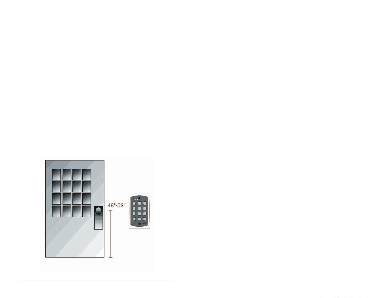
4. Mounting
Thekeypadisdesignedtobeflushmountedusingastandardsinglegang electrical box. In addition, it can be flush mounted directly to the
wallsurfacebycuttingaholeinthewall.Toproperlysizethemounting
and wire access hole, use the installation template on the last page in
this manual and on the unit’s container.
Mounting height can vary depending on requirements. An appropriate range is typically between 48 and 52 inches on center off the
floor.
For outdoorinstallations, use aweatherproof backbox and seal the wire
entry locations with silicone and provide a drain hole. In addition, use
the anti-oxidant grease pack for the wire harness connectors.
Figure 1 Keypad Mounting Height
6 Document # 6104400, Rev. 1.0, D1c
Page 7

e/eM Style Open Technology Keypad Installation/Programming Manual
5. Wiring
Figure 2 Connector Harness
Pin Wire Color Signal Name
1Red
2Black
3White/Black Data0
4 White/Yellow Data 1
5Brown LED1
6 White/Orange Not Used
7White NotUsed
8Green NotUsed
9Blue NotUsed
10 Gray Not Used
Document # 6104400, Rev. 1.0, D1c 7
V+ (Keypad
Power)
V- (Keypad
Power)
Page 8

e/eM Style Open Technology Keypad Installation/Programming
Manual
5.1 Wire Specifications
Connecting the keypad to an IEI controller or Wiegand panel requires a stranded wire cable with overall foil shield and drain
wire. Connect the drain wire at the controller end to your ground
wire.Atthekeypad,youmust cut back the drain wire and foil
shield and tape with electrical tape. The maximum wire distance is
shown in the table below.
Wire Gauge Wire Distance
18 AWG 1000 Feet
20 AWG 500 Feet
22 AWG 250 Feet
5.2 Connecting the Keypad to an IEI Hub Door
Controller
Only four wires are required to connect the keypad to an IEI Hub
DoorController.Connectthered(V+),black(V-),white/black
(Data 0) and white/yellow (Data 1) wires to the corresponding
wires on the IEI controller as shown in Figure 3.
Figure 3 Connecting the Keypad to Hub Door Controller
8 Document # 6104400, Rev. 1.0, D1c
Page 9

e/eM Style Open Technology Keypad Installation/Programming Manual
5.3 Connecting the Keypad to a Wiegand Panel
Only five wires are required to connect the keypad to a Wiegand
panel. Connect the red (V+), black (V-), white/black (Data 0),
white/yellow (Data 1) and brown (LED 1) wires to the corresponding wires on the Wiegand panel as shown in Figure 4.
Figure 4 Connecting the Keypad to a Wiegand Panel
Document # 6104400, Rev. 1.0, D1c 9
Page 10

e/eM Style Open Technology Keypad Installation/Programming
Manual
6. Testing the Keypad
After installing the keypad, IEI recommends that you perform the
keypad self-test once a year, to ensure that the keypad works properly.
• To perform the self-test, with the unit powered up, press
the following keys on the keypad:
7890#123456*
• If all 12 keypresses are accepted, the keypad enters self-test
mode.
• The LEDs alternate three times followed by the sounder
beeping three times.
• When finished (in Hub Front End mode only), the yellow
LED starts flickering rapidly.
• Press * to clear.
10 Document # 6104400, Rev. 1.0, D1c
Page 11
e/eM Style Open Technology Keypad Installation/Programming Manual
7. Programming
To enter program mode, enter your local Program Code by pressing
099 # Program Code * .
7.1 Programming Options Chart
Command/Action Keys to Enter/Details
Command 90.
Change Local Program
Code
Command 91.
Set/Clear Keypad
Options (options
below, defaults in bold)
Option Clear Set
0-visual keypress feedback 0=disabled 1=ENABLED
1-audio keypress feedback 0=disabled 1=ENABLED
3-front end select 0=HFE 1=wfe
4-HFE location 0=OUTSIDE 1=inside
5-WFE red led enabled 0=disabled 1=ENABLED
6-WFE red led active state 0=LOW 1=high
7-WFE green led enable 0=disabled 1=ENABLED
8-WFE green led active state 0=low 1=HIGH
10-PIN size test 0=DISABLED 1=enabled
11-keypad illumination 0=disabled 1=ENABLED
12-keypad dimming 0=disabled 1=ENABLED
HFE=Hub Front End WFE=Wiegand Front End
NOTE: Options 11 and 12 available only in e keypads.
90#0#0#code*code*(default=6789)
91#option#set/clear#**
Command 92.
Set Wiegand
Parameters
Parameter Value
1-Wiegand format 1-8 (defaults to 1=26 bit) (see Wiegand
2-Interpulse spacing 1-255 (defaults to 32= 64- microseconds)
3-Pulse width 1-255 (defaults to 8= 160 microseconds)
92 # parameter # value # **
Format chart)
Document # 6104400, Rev. 1.0, D1c 11
Page 12

e/eM Style Open Technology Keypad Installation/Programming
Manual
Command/Action Keys to Enter/Details
Command 93.
Set Wiegand ID’s
ID Type ID Value
0-site id See Wiegand Format chart (default=0)
1-group id See Wiegand Format chart (default=0)
Command 96.
Reset keypad
Settings to Default
93#IDType#IDValue#**
96#0#0#** Reset keypad to Hub
Front End
96#1#N#** Reset keypad to
Wiegand Front End
using wiegand format N.
7.2 Wiegand Format Chart
Format
Value
1 26 bit 65535 255 N/A
2 28 bit 32767 255 N/A
3 29 bit 524287 255 N/A
Wiegand
Format
Largest
PIN Value
Largest
Site Value
Largest
Group
Value
4 30 bit 65535 255 15
5 31 bit 65535 255 31
6 32 bit 8191 2047 63
7 36 bit 1048575 255 N/A
8 29 bit 524287 255 N/A
12 Document # 6104400, Rev. 1.0, D1c
Page 13

e/eM Style Open Technology Keypad Installation/Programming Manual
8. Troubleshooting
Refer tothis section if the keypadis not operatingcorrectly asdescribed
in this manual.
Problem Solution
The local program
code is not allowing
access to local
program mode.
No LED’s are lit on
the keypad.
The code works on
the controller but
does not work on
the keypad.
After performing the
keypad self-test, the
yellow LED is on
solid (not flickering
rapidly, HFE mode
only).
DEALERS/INSTALLERS ONLY! End users must contact dealer/installer
for support. If the keypad still does not work after troubleshooting,
please call IEI’s technical support department at 1-800-343-9502 (outside
MA) or 1-800-733-9502 (inside MA). Operating hours are Monday
through Friday from 8:00 A.M. to 7:00 P.M. Eastern Standard Time.
Perform the program mode loopback shown
in the next section (Figure 7) and reset the
local program code using command
90#0#0#code*code*
Power may not be reaching the keypad.
Using a voltmeter, verify that voltage is
reaching the keypad on the Red and Black
wires. If there is no voltage, verify the
voltage at the controller and power supply
and verify that there is no break in the
wires, then check continuity through the
whole length of the wire run. Also, when
using the keypad as a Wiegand front end,
verify that the LED wire is connected.
The data lines may not be connected. Verify
that both data lines are connected to the
keypad and controller and make sure there
is continuity through the whole length of the
wire run.
The data lines may not be connected. Verify
that both data lines are connected to the
keypad and controller and make sure there
is continuity through the whole length of the
wire run.
Document # 6104400, Rev. 1.0, D1c 13
Page 14

e/eM Style Open Technology Keypad Installation/Programming
Manual
9. Wire Harness Loopback
Connections
Ifthefourdatawiresareshortedinoneofthetwoconfigurations
shown below on power up, the option is set. To connect, remove
power after you hear the three beeps and then reconnect the data
lines to their proper working configuration.
9.1 Defaulting Door-Gard/Setting in Hub Front
End Mode
First, disconnect power from the system, then connect the
White/Black Wire (Data 0) to the White Wire and connect the
White/Yellow Wire (Data 1) to the Brown Wire (LED 1), as shown
in Figure 5, and power up the keypad.
Figure 5 Hub Front End Loopback
14 Document # 6104400, Rev. 1.0, D1c
Page 15

e/eM Style Open Technology Keypad Installation/Programming Manual
9.2 Defaulting Door-Gard/Setting in 26-bit
WiegandFrontEndMode
First, disconnect power from the system, then connect the White/Black
Wire (Data 0) tothe Brown Wire (LED 1) and connect the White/Yellow
Wire (Data 1) to the White Wire, as shown in Figure 6, and power up
the keypad.
Figure 6 Wiegand Front End Loopback
9.3EnteringProgramModeUsingtheWire
Harness
If the local program code is either not working or forgotten, power
down the system, connect the wire harness as shown below, and then
power the system up again. Next, change your local program code and
power down the system and restore the wire harness to its original
configuration and turn the power on again.
First, disconnect power from the system, then connect the
White/Yellow Wire (Data 1) to the Brown (LED 1) and White Wire,
asshowninFigure7,andpowerupthekeypad.
Figure 7 Program Mode Loopback
Document # 6104400, Rev. 1.0, D1c 15
Page 16

e/eM Style Open Technology Keypad Installation/Programming
Manual
10. Warranty
International Electronics Inc. (IEI) warrants its products to be free
from defects in material and workmanship when they have been
installed in accordance with the manufacturer’s instructions and
have not been modified or tampered with. IEI does not assume
any responsibility for damage or injury to person or property due
to improper care, storage, handling, abuse, misuse, normal wear
and tear, or an act of God.
IEI’s sole responsibility is limited to the repair (at IEI’s option) or
the replacement of the defective product or part when sent to IEI’s
facility (freight and insurance charges prepaid) after obtaining
IEI’s Return Material Authorization. IEI will not be liable to the
purchaser or any one else for incidental or consequential damages
arising from any defect in, or malfunction of, its products.
Except as stated above, IEI makes no warranties, either expressed
or implied, as to any matter whatsoever, including, and without
limitation to, the condition of its products, their merchantability, or
fitness for any particular purpose.
Warranty Periods Are:
1Year PowerKey
2 Years Door Gard & Secured Series
Products
2 Years LS Series
2 Years Glass Break
5 Years ‘e’ and ‘eM’ Style Keypads
Allproductshavedatecodelabelingtodeterminethewarrantyperiod.A
90-day grace period is added to all products to account for shelf life.
16 Document # 6104400, Rev. 1.0, D1c
Page 17

Page 18

Page 19

Page 20

 Loading...