

Page 1

Max 3 Modem Module Installation Instructions
For Use with Max 3 and MiniMax 3 Systems
Specifications/Requirements:
Mechanical: Electrical:
2.90” W x 3.45” L x 0.81” D Operating Voltage: 12VDC (Power from Max 3 Do or Control Module)
Current Draw: 75mA
Environmental:
Environment: Indoor Only Software Compatibility:
Temperature Tolerance: 32º F to 120º F (0º – 49ºC) Hub Manager Professional Version 7.4 (or higher)
Communication Speed
Baud Rate: 19200kbps
Description
The IEI Max3 modem module is used for dial up remote site management applications. The modem is designed for easy plug-on
installation to Max 3 Door Control Modules for Max 3 and MiniMax 3 systems. The following sections discuss the system
requirements, installation and wiring.
Software Compatibility
The Max 3 Modem is compatible with Hub Manager Professional Version 7.4 (or higher). You can also download the latest version of
software at www.ieib.com or update your existing software through iUpdate.
Technical Support
Service Company: To contact IEI’s Technical Support department, call 1- 800-343-9502, Monday through Friday. Questions can also
be submitted through our website at www.ieib.com
End User: Please contact your service company.
.
Packing List
(1) Max 3 Modem Module
(1) Installation Instructions
(1) RS-485 Wire Harness (green, blue and gray)
(1) Power Wire Harness (red and black)
(1) Ground Wire (black)
3
/4” Metal Standoffs for Mounting
(3)
(1) Hub Manager Professional Software CD
(1) 6-Foot Cord
(1) External RJ-11 Jack
15.21 Information to User
Any changes or modifications not expressly approved by the party responsible
for compliance could void the user’s authority to operate the equipment.
Document #: 6060556 Rev 1.0, D1c Page 1 of 4
Page 2

Mounting the Max 3 Modem Module
The Max 3 Modem is designed to mount on top of the first module in the system. Follow the instructions and the diagram below to
mount and wire the Max 3 Modem.
1. Turn off power to the first Max 3 Module by placing SW1 on the backplane into the OFF position.
2. Remove the programming keypad (if installed) from the first Max 3 Module in the system.
3. Remove the three
3 Modem onto the threaded posts supporting the Max 3 Module to increase the height off the module.
4. Place the Max 3 Modem onto the three stand-offs.
5. Secure the Max 3 Modem using the
Caution: Do not turn power back on un til after you have completed wiring the Max 3 Modem Module.
1
/2” stand-offs used to secure the Max 3 Module, then thread the three 3/4” stand-offs supplied with the Max
1
/2” stand-offs removed in step 1.
Note: MiniMax 3 Systems previously used
nylon stand-offs to mount the Max 3 Module. If
your system does not have the metal stand-offs
required for mounting the Max 3 Modem
Module, please contact IEI technical support.
Document #: 6060556 Rev 1.0, D1c Page 2 of 4
Page 3

Wiring the Max 3 Modem Module
Follow the instructions below for wiring a Max 3 Modem Module to a new Max 3 or MiniMax 3 System.
Caution: Power must be off prior wiring the Max 3 Modem Module.
1. Connect RS-485
● Connect J2 on the Max 3 Modem to P5 on the Max 3 Module, using the three-position wire harness (green, blue, gray),
that is provided with your Max 3 System.
● Connect J3 on the Max 3 Modem to the backplane (J1 on a Max 3 OR P1 on a MiniMax 3), using the three-position wire
harness (green, blue, gray), that is provided with your Max 3 Modem Module.
2. Connect Power
● Connect J1 on the Max 3 Modem to P3 on the Max 3 Module using the red and black wire harness that is provided w ith
your Max 3 Modem Module.
3. Connect Earth Ground
● Plug the black ground wire onto the fast-tab E1 on the Modem, then connect it to the fast-tab on the backplane (TAB1 on
MiniMax 3 OR FT1 on Max 3). Note: This is the same fast-tab used for your front-end shield.
4. Connect the Phone Line
● Wire the TIP and RING lines from your phone line to the external RJ-11 Jack provided with the Max 3 Modem. TIP goes
to the GREEN wire and RING goes to the RED wire. Note: If you already have a phone jack near your Max 3 System,
this step may not be required.
● Plug the 6-Foot Cord provided with the Max 3 Modem into the external RJ-11 jack (or existing phone jack), then into the
RJ-11 jack on the Modem labeled PHONE LINE (P2).
5. Turn on power to the first Max 3 Module by placing SW1 on the backplane into the ON position.
Note: The local/remote switch
on the backplane does not
apply to the Max 3 Modem
Document #: 6060556 Rev 1.0, D1c Page 3 of 4
Page 4
Converting a Serial Connected Max 3 System to a Modem Connection
Follow the instructions below to convert a serial connected Max 3 system to a modem connection. Refer to the diagram on the
previous page.
Caution: Power must be off prior wiring the Max 3 Modem Module.
1. Connect RS-485
● Disconnect your USB to Serial Converter OR RS-232 to RS-485 Converter from TS3 on the backplane.
● Disconnect the three-position wire harness (green, blue, gray) from P5 on the Max 3 Module (leave the other end
connected to the backplane).
● Connect the three-position wire harness (green, blue, gray) from the backplane to J3 on the Max 3 Modem.
● Connect J2 on the Max 3 Mode m to P5 on the Max 3 Module using the three-position wire harness (green, blue, gray)
that is provided with your Max 3 Modem Module.
2. Connect Power
● Connect J1 on the Max 3 Modem to P3 on the Max 3 Module using the red and black wire harness that is provided with
your Max 3 Modem Module..
3. Connect Earth Ground
● Plug the black ground wire onto the fast-tab E1 on the Modem, then connect it to the fast-tab on the backplane (TAB1 on
MiniMax 3 OR FT1 on Max 3). Note: This is the same fast-tab used for your front-end shield.
4. Connect the Phone Line
● Wire the TIP and RING lines from your phone line to the external RJ-11 Jack provided with the Max 3 Modem. TIP goes
to the GREEN wire and RING goes to the RED wire. Note: If you already have a phone jack near your Max 3 System,
this step may not be required.
● Plug the 6-Foot Cord provided with the Max 3 Modem into the external RJ-11 jack (or existing phone jack), then into the
RJ-11 jack on the Modem labeled PHONE LINE (P2).
5. Turn on power to the first Max 3 Module by placing SW1 on the backplane into the ON position.
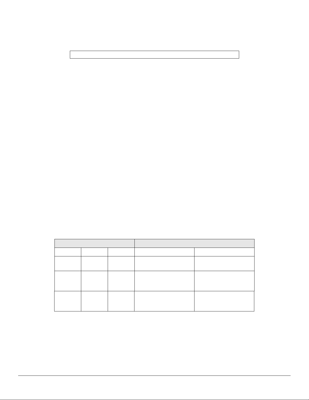
Modem LED Indications
The chart below describes the three LED indicator s on the Max 3 Modem Module.
LED
LED Label Color
LED 1 RI Red Ring Indicator
LED 2 DCD Red Data Carrier Detect
LED 3 POWER Green Modem Power
Function Details
Description
Flashes when ringing; Off
normally
Turns on solid when
connected; Off when
disconnected
Turns on solid when power
turned on; Off when not
powered.
Document #: 6060556 Rev 1.0, D1c Page 4 of 4
 Loading...