

Page 1
Operations and
Installation Manual
I
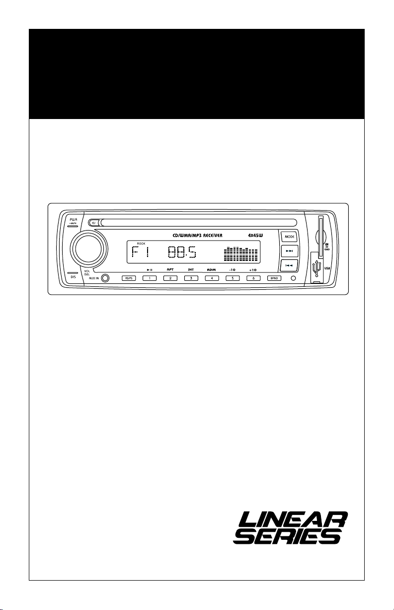
M3300CD
AM / FM Receiver with
CD Player
A Registered Trademark of Magnadyne Corporation
®
Page 2
Introduction
Your new M3300CD in-dash entertainment system has been designed to give you many years of listening
pleasure. Take a moment to read through this manual and become familiar with the operations and features
of this outstanding product.
It is advisable to keep this manual in your vehicle so it is readily available for reference. Be sure to fill out
and send in your warranty card to ensure that you receive the full benefits of warranty repair in the unlikely
event that your system will need service. We are confident that you will thoroughly enjoy your new mobile
entertainment system.
Caution
• FCC REGULATIONS STATE THAT ANY UNAUTHORIZED CHANGES OR MODIFICATIONS TO THIS
EQUIPMENT MAY VOID THE USER’S AUTHORITY TO OPERATE IT.
• TO REDUCE THE RISK OF FIRE OR ELECTRIC SHOCK, DO NOT EXPOSE THIS EQUIPMENT TO RAIN OR
MOISTURE.
• THIS DEVICE IS INTENDED FOR CONTINUOUS OPERATION.
• TO REDUCE THE RISK OF FIRE OR ELECTRIC SHOCK AND ANNOYING INTERFERENCE, USE ONLY THE
RECOMMENDED ACCESSORIES.
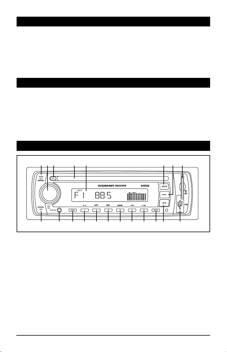
Location and Function of Controls at a Glance
1 3 4 52 6 7 8
I
1011121314151617181920
1. Power and Mute Button (PWR / MUTE):
Power: Press any button to turn on the unit. Press and hold the PWR button to switch the unit off.
Mute: With the unit on press the PWR/MUTE button to turn the audio off. Press again to restore
the audio.
2. Volume/Select Knob (VOL/SEL)
Volume: Rotate VOL knob to adjust the volume level.
Select: Press the VOL knob to enter the sound characteristics menu. The first item on the
menu will be volume, each press of the VOL knob will change the menu item as follows:
VOLUME > BASS > TREBLE > BALANCE > FADER.
3. Eject Button (EJ): Ejects the disc from the CD slot.
4. CD Slot: Insert a CD into the slot with label facing up.
5. Display Area: Displays: radio, clock, disc, SD card and USB functions.
9
2
Page 3

Location and Function of Controls at a Glance (continued)
6. Mode Button (MODE): Press the MODE button to change the operating mode as follows:
RADIO > CD* > USB* > SD* > AUX > RADIO.
*Available only when there is media inserted into Disc slot, SD card slot or USB slot.
7.
Track Up Button ( l ): Adjusts the radio frequency, changes tracks and sets the clock.
8. SD Card Slot: Insert a SD card with the notch in the card facing up, “SD” will appear in the display
9. USB Input: Plug in your USB device, “USB” will appear in the display.
10. Track Down Button ( l
11. Radio Band Button (BAND): Selects the desired radio band in the following order: F1, F2, F3, A1 and A2.
12. Multi-Function Button (6, +10):
Radio: Recalls a memorized radio station, and programs a radio station into memory.
CD, SD or USB: Press to skip up 10 tracks.
13. Multi-Function Button (5, -10):
Radio: Recalls a memorized radio station, and programs a radio station into memory.
CD, SD or USB: Press to skip down 10 tracks.
14. Multi-Function Button (4, RDM):
Radio: Recalls a memorized radio station, and programs a radio station into memory.
CD, SD or USB: Press to randomly play tracks.
15. Multi-Function Button (3, INT):
Radio: Recalls a memorized radio station, and programs a radio station into memory.
CD, SD or USB: Press to activate the intro function which will play the beginning of every track for
10 seconds.
16. Multi-Function Button (2, RPT):
Radio: Recalls a memorized radio station, and programs a radio station into memory.
CD, SD or USB: Press to repeat the current track. Press again to cancel the repeat function.
): Adjusts the radio frequency, changes tracks and sets the clock.
.
17. Multi-Function Button (1, ll):
Radio: Recalls a memorized radio station, and programs a radio station into memory.
CD, SD or USB: Press to pause the current track. Press again to resume play.
18. AS/PS Button: Automatic radio station memory storing and preset radio station scanning.
19. 3.5mm Auxiliary Audio Input Jack: Plug in a device with a 3.5mm audio input plug.
20. Display Button: Press the DIS button to toggle through the available display information. In the radio
mode, program station name (PS) is the default, if not available the frequency will be displayed.
Toggle sequence: CT(clock/time)--PTY-- PS (program service, only if there is station)-- Exit Display.
3
Page 4

Radio Operation
Select a Band
Press the MODE button until either F1, F2, F3, A1
or A2 appear in the display. Next press the BAND
button to select the desired band: F1, F2, F3, A1
or A2.
Tuning
Automatic Search Tuning: Press the l or
l button to move to the next or previous sta-
tion automatically.
Manual Tuning: Press and hold the l or l
button until “MANUAL” appears in the display.
Then press and release the l or l button until desired frequency is selected. The unit
will default back to “AUTO” tuning mode after 5
seconds of no button activity.
Preset Stations
Six numbered preset buttons store and recall
stations for each band. Select a band (if needed).
Select a station by pressing the l or l
button. Press and hold any of the preset buttons
for three seconds to memorize the station. The
preset number will appear in the display.
Recall a Station:
one of the six preset buttons to select a stored
station.
Automatic Preset Station Memory Store:
band (if needed). Press and hold the button AS/
PS button for two seconds. The radio automati-
cally selects six strong stations and stores them
in the current band. The new stations replace
stations already stored in that band.
Note: During Automatic Memory Store, the unit
will search and store stations with the strong
signals first, and then weaker signal stations
until the memories are full.
Preset Scan:
current band press the AS/PS button momentarily.
The radio pauses for five seconds at each preset
station. When the desired station is reached,
press the AS/PS button again to stop scanning.
FM Stereo/Mono Reception
For weaker FM stereo stations selecting mono
reception usually improves reception. To switch
from stereo to mono reception push and hold
the VOL knob for a few seconds then release.
Continue to press the knob until “STEREO”
appears in the display. Rotate the VOL knob until
“MONO” appears in the display. The unit will
leave feature programing after 5 seconds of no
button activity.
Select a band (if needed). Press
Select a
To scan preset stations stored in the
Local/Distant Reception
To narrow the reception to only local strong station the radio must be switched from distant to
local reception. To switch from distant to local
reception push and hold the VOL knob for a
few seconds then release. Continue to press the
knob until “DX” appears in the display. Rotate
the VOL knob until “LOCAL” appears in the display. The unit will leave feature programing after
5 seconds of no button activity.
RBDS Overview
RBDS (Radio Broadcast System) service availability varies from area to area. If RBDS service is
not available in your area, the following services
are not available:
PS: Program Service Name Broadcast - station
name data expressed in alphanumeric characters.
TP: Traffic Program Identification - for traffic
information broadcasting station.
TA: Traffic Announcement Identification - showing traffic information is being transmitted or not.
TA (Travel Announcement) / TP (Travel Program
Identification)
Enable or disable TA mode by pressing and holding the BAND button. (Default is Disabled)
1. Long press BAND button once to activate the
function, press again to turn off the function.
2. When TA function is activated, it will search
the station with TA information automatically.
If there is not TA information, it will search the
station with TP information automatically, if
there is no TP information either, it will return
to the previous station after searching.
3. When receiving the station with TP information
but without TA information, TP icon is on and
TA icon keeps blinking; when receiving the station with TP and TA information, both TP and
TA icons are on.
4. When playing in another mode and TA information is received, the unit will change to the
radio mode automatically. After the TA information is finished, it will return to the previous
mode. The AS/PS, Preset (1-6), DIS, MODE,
l , l and BAND buttons are locked.
Press BAND button one to ignore the received
TA information, press BAND button twice to
turn off the function.
4
Page 5

Radio Operation (continued)
TA Seek / TA Alarm
In TA Alarm mode, the alarm is set off.
1. Press and hold the VOL knob for a few sec-
onds then release.
2. Continue to press the knob until “TA ALARM”
appears in the display.
3. Rotate the VOL knob until “TA SEEK” appears
in the display. In TA SEEK mode, the unit will
seek for Traffic Announcement program.
Sound Controls
Volume
Rotate the VOL knob clockwise to increase the volume and counterclockwise to decrease the volume.
Sound Characteristics Menu
By pressing the VOL knob, the modes will be
displayed in the following order: Volume, Bass,
Treble, Balance and Fader.
Bass
Press the VOL knob two times. Turn the VOL knob
clockwise to increase the bass and counterclockwise to decrease the bass.
Treble
Press the VOL knob button three times. Turn the
VOL knob clockwise to increase the treble and
counterclockwise to decrease the treble.
Balance
Press the VOL knob button four times. Turn the
VOL knob clockwise to increase the balance to
the right and counterclockwise to increase the
balance to the left.
Fader
Press the VOL knob button five times. Turn the
VOL knob clockwise to increase the balance to the
front speakers and counterclockwise to increase
the balance to the rear speakers.
PTY (Program Type)
1. Press and hold DIS button to activate the PTY
function.
2. Rotate the VOL knob to select the PTY type.
3. When the program type you want to search for
is displayed, press the DIS button to search for
the selected program type. Press the DIS button again to stop the PTY search.
Note: If PTY code is different or not available,
LCD blinks with “PTY NONE”.
Loud
Enhances high frequency and low frequency
sound quality. To switch the loudness push
and hold the VOL knob for a few seconds then
release. Continue to press the knob until “LOUD
OFF” appears in the display. Rotate the VOL knob
until “LOUD ON” appears in the display. The unit
will leave feature programing after 5 seconds of
no button activity.
Mute
Press the PWR/MUTE button to turn the sound
off. Press it again to restore the audio.
Sub Woofer
Press and hold the MODE button to enable or
disable the Sub Woofer output. When the Sub
Woofer output is enabled, “SW” appears in the
display.
Equalizer
The M3300CD has pre-programmed audio settings. To switch the equalizer settings push
and hold the VOL knob for a few seconds then
release. One of the following equalizer setting
will appear: POP M, ROCK M, DSP OFF, FLAT or
CLASSICS. Rotate the VOL knob until the desired
setting appears in the display. The unit will leave
equalizer programing after 5 seconds of no button activity.
Note: If the bass or treble is adjusted the equalizer setting will revert to the DSP OFF setting.
5
Page 6

General Operations
Turning the Unit On
Press any button to turn on the unit. Press and
hold PWR button to switch the unit off.
Mode:
Press the MODE button to change the operating
mode as follows:
RADIO > CD* > USB* > SD* > AUX > TUNER.
*Available only when there is media inserted
into Disc slot, SD card slot or USB slot.
Setting the Clock
Press the DIS button so the clock is displayed.
Press the button again and hold for 3 seconds
until the time flashes, then release. Then press
the l button to adjust the minutes, and press
the l button to adjust the hours.
12 hr (am/pm) or 24 hr (military) Format
Press and hold the VOL knob for a few seconds then release. Continue to press the knob
until “12 HOUR” appears in the display. Rotate
the VOL knob until “24 HOUR” appears in the
display. The unit will leave feature programing
after 5 seconds of no button activity.
CD, USB and SD Card Operation
Loading and Ejecting a CD
Insert a CD into the CD Slot, label side up, and the
CD will begin to play.
Press the EJ button to stop CD play and eject the
CD from the slot.
Inserting the SD Card or USB Device
Insert the SD card into the SD card slot and insert
a USB memory into the USB input. The mode will
automatically change to SD or USB mode.
To remove the SD card:
Push in on the SD card until you hear a click,
then release the SD card and remove it.
To remove the USB memory:
Pull the USB memory out of the USB input.
Note: This unit may not play all SD cards or USB
memory devices. The manufacturer of this unit
is not responsible for any data loss. We suggest
you back-up your data.
Select Tracks
Press the l or l button for less than a
second to move to the next or previous track. The
track number appears in the display area.
Display Button
The display feature allows you to see the clock
and information for the current operating mode.
Each press will change the information displayed.
Audio Beep
Press and hold the VOL knob for a few seconds
then release. Continue to press the knob until
“BEEP 2ND” appears in the display. Rotate the
VOL knob to select the desired beep mode:
BEEP 2ND = Beep on Press and Hold
BEEP ALL = When Pressing any Button.
BEEP OFF = No Beep Sound.
The unit will leave feature programing after 5
seconds of no button activity.
3.5mm Auxiliary Input Jack
Plug an audio device into this jack. This allows
you to listen to an auxiliary audio source (MP3
player, portable cassette player, etc). Connect
the proper cable (not supplied with this unit).
Press the MODE button until “AUX” appears in
the display to access the auxiliary device’s audio.
Note: The M3300CD will not control the auxiliary
audio source.
Fast Forward and Fast Reverse
Press the l or l button for more than one
second to fast forward or fast reverse. CD play
starts from when you release the button.
Pause Play
Press the 1/ ll button to pause play. Press it
again to resume play.
Repeat the Same Track
Press the 2/RPT button to continuously repeat
the same track. Press it again to stop repeat.
Note: After finishing all tracks or all folders the unit
restarts playing all tracks for all folders automatically.
Intro Scan
Press the 3/INT button to play the first ten sec-
onds of each track. Press it again to stop intro
scan and listen to the track.
Play All Tracks in Random Order
Press the 4/RDM button to play all tracks in random
order. Press it again to stop playing in random order.
Track Skip Buttons
Press the 5/-10 button to skip down 10 tracks.
Press the 6/+10 button to skip up 10 tracks.
6
Page 7

CD, USB and SD Card Operation (continued)
File / Folder Search Function
When playing MP3/WMA files from a CD, USB
Memory or SD/MMC Card, press AS/PS button
to enter search mode.
Sequence of search modes:
File Number Search -> File Name Search ->
Folder Search -> Exit search mode.
Note: Commercial audio-CD discs only support
file number search.
File Number Search
1. Press AS/PS button to enter file number
search.
2. “MP3 T*” is displayed and the* blinks to
show the unit is ready to accept a file number
to search for.
3. Rotate the VOL knob to input a digit, from 0 to
9, of the track you want to listen to.
4. Press the VOL knob to move to the next digit.
After completing input, press BAND/ENT button to play.
File Name Search
1. Press AS/PS button until an asterisk “*“
blinks on left side of LCD.
2. Rotate the VOL knob to input letters (from A
to Z) or a number (from 0 to 9) of the file you
want to listen to.
3. Press the VOL knob to change to the next
character.
4. After completing input, press BAND/ENT but-
ton to play.
Note:
If there is no file found, the unit will return
to initial input ready mode automatically.
Folder Search
1. To start folder search, press the AS/PS button
3 times. The word “ROOT” will be displayed
on LCD, then the name of the first folder will
be displayed.
2. Rotate the VOL knob change the folder.
3. Press the BAND button to select the displayed
folder.
7
Page 8

Installation Procedures
S
tep 1: The radio chassis is designed to be “Sleeve
Mounted” through a opening in the dashboard panel.
The required opening size is 182mm (7-3/16”) x
52mm (2-1/16”). Cut or enlarged an opening in the
dashboard to accommodate the mounting sleeve.
Step 2: If you are replacing an existing factory
installed radio, an adapter harness might be available for your vehicle to eliminate the need for
cutting your factory wiring. Contact Radio Shack
or other car stereo installation centers for the availability of a harness for your vehicle.
Step 3: Insert the mounting sleeve into the hole in
the dashboard. Bend the metal tabs on the sleeve to
secure the mounting sleeve to the dashboard.
Step 4: Bring all wiring for the connection of the
unit (including the antenna) through the center of the
mounting sleeve. Connect the wiring as follows:
Yellow Wire: Connect this wire to a constant +12
volt power source (a power source that is not controlled by the ignition key).
Red Wire (with Fuse): Connect this wire to a
switched +12 volt power source (a power source
turned on and off by the ignition key).
Blue Wire: Connect this wire to the (+) power
antenna activation circuit or remote amplifier activation. If no power antenna or amplifier exists,
tape-off the end of this wire to prevent shorting
out the unit.
Black Wire: Connect this wire to the frame of the
vehicle (ground). This wire is the chassis grounding
wire for the unit.
White Wire: Connect this wire to the Left Front
Speaker (+) positive terminal or wire.
White Wire with Black Stripe: Connect this wire to the
Left Front Speaker (-) negative terminal or wire.
Gre
en Wire with Black Stripe: Connect this wire to the
Left Rear Speaker (-) negative terminal or wire.
Green Wire: Connect this wire to the Left Rear
Speaker (+) positive terminal or wire.
Gray Wire: Connect this wire to the Right Front
Speaker (+) positive terminal or wire.
Gra
y Wire with Black Stripe: Connect this wire to the
Right Front Speaker (-) negative terminal or wire.
Purple
Wire with Black Stripe: Connect this wire to
the Right Rear Speaker (-) negative terminal or wire.
Purple Wire: Connect this wire to the Right Rear
Speaker (+) positive terminal or wire.
Brown Cable with Red/White RCA Connectors:
Provides Left and Right Channel audio signal output
for input to an additional amplifier.
Black Cable with Blue RCA Connector: Provides
Sub Woofer audio signal output for input to an
additional amplifier.
Note 1: This unit is designed to connect to (4) four
speakers. If the installation only requires (2) two
speakers, use the White and Gray wire sets to connect the speakers.
Note 2: If installation angle exceeds 30 degrees
from horizontal, the unit might not give its optimum
performance.
Note 3: Avoid installing the unit where it would be
subject to high temperature, such as from direct
sunlight, or from hot air, from the heater, or where is
would be subject to dust, dirt or excessive vibration.
Remove Transportation Screws: Before installing
the unit, please remove the two screws shown in
the illustration below.
Remove Transportation
Screws Before
Installation
WARNING!
Any wires left unconnected must be taped-off
or capped-off to prevent shorting.
DO NOT connect speaker ground wires together.
DO NOT connect speaker ground wires to the
chassis of the vehicle.
DO NOT connect front and rear speaker wires
together.
FAILURE TO FOLLOW ANY OF THESE
WARNINGS WILL RESULT IN DAMAGE TO
THIS UNIT AND VOIDS THE WARRANTY.
8
Page 9
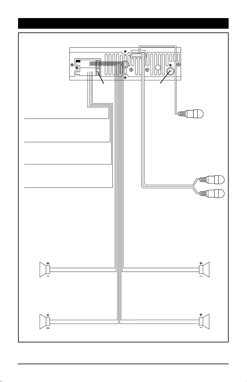
Wiring Diagram
Red Wire
Ignition Switch (+12v in )
Yellow Wire Battery (+12v in)
Black Wire Ground (B-)
Blue Wire Power Antenna (Switched 12v out)
Left
Front
Speaker
White Wire
White Wire with Black Stripe
15 A
Fuse
Antenna
Socket
Sub Woofer
Audio Line Output
Gray Wire
Gray Wire with Black Stripe
Red
Right
Channel
White
Left
Channel
Right
Front
Speaker
Left
Rear
Speaker
Green Wire
Green Wire with Black Stripe
Violet Wire
Violet Wire with Black Stripe
Right
Rear
Speaker
9
Page 10

Audio Line Out Connection
M3300CD
Red (Right)
White (Left)
Sub Woofer Connection
M3300CD
Blue (Sub Woofer)
Final Installation - Method A
Mounting Sleeve
Push Out Mounting
Sleeve Tabs
Cable Not Supplied
Cable Not Supplied
Metal Strap
Dashboard
Optional
Speaker
Amplifier
Optional
Sub Woofer
Amplifier
Sheet Metal
Screw
Nut
Washer
Installing the Unit
1: Insert the sleeve into the dashboard opening and
bend the mounting tabs outward to secure it.
2:
If necessary, attach the mounting strap to the rear
of the unit, then attach it with the supplied nut.
3:
Insert the unit into the sleeve until you hear a click.
4: Finally place the trim ring over the unit.
10
Removal Keys
Removing the Unit
1: Remove the trim ring.
2: Insert the release keys into the left and right
side of the unit.
3: Pull the unit out of the dashboard.
Page 11

Final Installation - Method B
1
3
2
3
5
2
Installing the Unit
1: Screw holes on the side of the unit.
2: Screws. Use wither truss screws (5 x 8mm) or
flush surface screws (4 x 8mm), depending on
the shape of the screw holes in the bracket.
3: Vehicle’s factory mounting bracket.
4: Dashboard or console.
5: Hook (Remove this part).
Specifications
CD Player
Signal/Noise Ratio ............................... > 60 dB
Frequency Response ............... 20 Hz – 20 kHz
Channel Separation .............................. > 62 dB
FM Tuner
Tuner Range ........................ 87.5 – 107.9 MHz
Usable Sensitivity ................................. 5 dBuV
Stereo Separation @ 1 kHz ..................... 28 dB
AM Tuner
Tuner Range ........................... 530 – 1710 kHz
Usable Sensitivity .................................... 30qV
4
Note: The mounting sleeve, outer trim ring, and
the mounting strap are not used for this method of
installation.
General
Operating Power ...... 12 VDC, Negative Ground
Maximum Power Output .............. 4 x 45 Watts
RMS Power ................................. 4 x 19 Watts
RCA Line Out ...... Low-Level Outputs - 1000MV
Output Impedance
Fuses .....................................................15 amp
Dimensions ...... 178 (w) x 178 (d) x 51 (h) mm
Specifications are subject to change without notice.
..
Compatible 4-8 Ohm Speakers
11
Page 12

Warranty
ONE (1) YEAR LIMITED WARRANTY
Magnadyne Corporation or its authorized agents will within one year from the date of sale to
you, repair, replace or refund the retail sales price of said product or any part thereof, at the
option of the Magnadyne Corporation or its authorized agents, if said product or part is found
defective in materials or workmanship, when properly connected and operating on the correct power requirements designated for the specific product. This warranty and Magnadyne
Corporation or its authorized agents obligations hereunder do not apply where the product
was; damaged while in the possession of the consumer, subjected to unreasonable or unintended use, not reasonably maintained, utilized in commercial or industrial operations, or
serviced by anyone other than Magnadyne Corporation or its authorized agents, or where the
warning seal on the product is broken or the power and/or plugs are detached from the unit.
Magnadyne Corporation or any of its authorized agents will not assume any labor costs for
the removal and reinstallation of any product found to be defective, or the cost of transportation to Magnadyne Corporation or its authorized agents. Such cost are the sole responsibility
of the purchaser.
This warranty does not cover the cabinet appearance items or accessories used in connection with this product, or any damage to recording or recording tape, or any damage to the
products resulting from improper installation, alteration, accident, misuse, abuse or acts of
nature.
MAGNADYNE CORPORATION OR ITS AUTHORIZED AGENTS SHALL NOT BE LIABLE TO
ANYONE FOR CONSEQUENTIAL OR INCIDENTAL DAMAGES OR CLAIMS EXCEPT THOSE
ACCORDED BY LAW. NO EXPRESSED WARRANTY OR IMPLIED WARRANTY IS GIVEN
EXCEPT THOSE SET FORTH HEREIN. NO IMPLIED WARRANTY SHALL EXTEND BEYOND
ONE YEAR FROM THE DATE OF SALE.
This warranty extends only to the original purchaser of the product and is not
transferable. Some states do not allow limitations on how long an implied warranty lasts, and
some states do not allow the exclusion or limitation of incidental or consequential damages,
so the above limitations or exclusion may not apply to you. This warranty gives you specific
legal rights, and you may have other rights that vary from state to state.
Defective merchandise should be returned to the original point of purchase or
secondly, to:
Magnadyne Corporation
1111 W. Victoria Street
Compton CA 90220
www.magnadyne.com
Return Authorization must be obtained before sending, or merchandise may be refused.
© Copyright 2010 Magnadyne Corporation
M3300CD-UM Rev. A 1-5-11
 Loading...