

Page 1
2003 INTERNATIONAL ELECTRONICS, INC.
427 TURNPIKE STREET, CANTON, MA 02021
(781) 821-5566 www.ieib.com
FAX INFO CENTER: (781) 821-0734
MORTISE LOCKSET
Installation Instructions
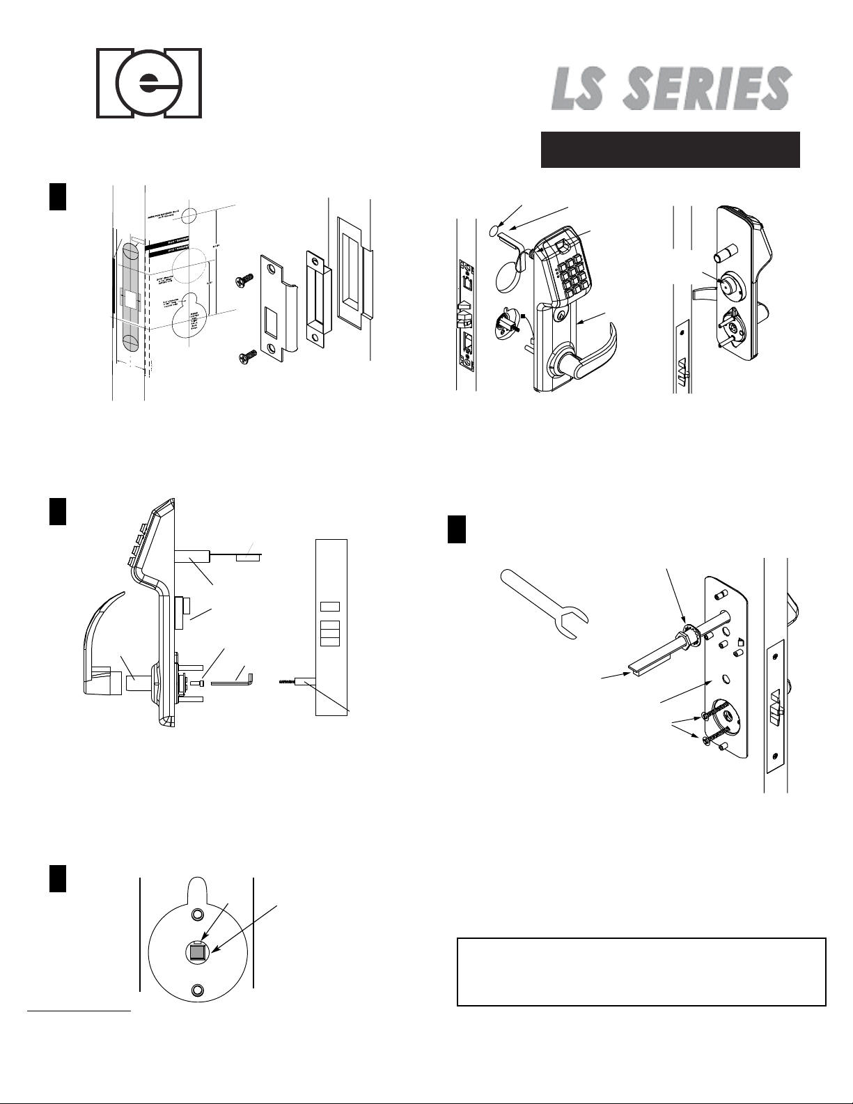
1
STRIKE
LIP
POSITION
1î
DIAMETER
Clearance
Anti-friction
for
latch
3/4î
Deep
of Hubs
Vertical
Center
line
of lock
C
L
1-3/4î
For
other
door
place
thicknesses,
on center
tear
line
of
of
f
door
and
edge.
Figure1
See template for measurements. See page 3 for instructions on
installing the lock body.
Affix template to door and follow template instructions
in preparing door as illustrated in Figure 1. Install strike correct for
handing and dust box.
Figure 2
2
Raceway
wires
Threaded
raceway
Cylinder plug
Wire Hole
Raceway
wires
Raceway
Tube
Cylinder
Plug
Exterior
Housing
2. Pass the
Raceway wires
through the wirehole, then
mount exterior housing through door preparation.Make sure
the spindle engages with the rotating hub in thecorrect
orientation, and the cylinder plug enters cylinder hole
in mortise lock.
Remove screw from Battery Cover to access interior backplate.
4
Lockwasher
Tube
Set Screw
Allen Wrench
Spindle /spring
Assemble Lever
assembly
1. Assemble inside and outside levers on shafts for
correct handing, using screw inside shaft to secure levers.
2. Locks auto adjust for 1 3/4" to 2 1/2" thick doors.
3. Locks are supplied either with 1 1/8" cylinder, or
prepped for a 1 1/8" cylinder (customer supplied). For
other options several purchased collar required.
3
Slot
1. VERY IMPORTANT
Align outside rotating hub in exterior housing so the slot is facing
up. Insert spindle spring assembly into outside lock hub.
Rotating Hub
Raceway
wires
Interior Backplate Assy
10-32x3/4" Thru-bolts
1. While holding the interior backplate in position, loosely
install the raceway nut first, then the two screws through
backplate and into posts.
2. Tighten the raceway nut on the raceway tube using
wrench supplied. When this connection is firm, secure
the thru-bolts.
Raceway wires- see separate instructions. LS-1 series
require motor cable connection to battery. LS-2 & LS-2P
series require motor cable connection; flex circuit connection;
and optional REX and door position switch connections.
Page 1
P/N 6043100 REV 1.0
Page 2

Installation Instructions
5
Figure 5
Raceway wires
7
Note: remove red ribbon
to activate batteries.
Figure 7
Battery
Cover
Center
Groved Stud
Brass #8-32 x 1/2" Lg
FHMS
Spindle/Spring
Assy.
#8-32 x 3/4" Lg
Oval HMS
Inside Lower
Housing Assy
1. Assemble the inside lower housing on backplate, while
engaging the spindle in lock hub. (Be sure wires are not
pinched.)
2. Fasten with two brass #8 screws and the finished #8 screw
at the bottom.
Center
6
Figure 6
Groved Stud
#8-32 x 3/4" Lg
Oval HMS
Inside Lower
Housing Assy
PUSH ALL EXCESS WIRE LENGTHS DOWN THROUGH
THE OPENING AT THE TOP OF THE INSIDE LOWER
HOUSING.
1. Attach the battery cover with two finished #8 screws. Battery cover
has a lip which engages the lower inside housing. It is important
that this lip be seated properly to insure correct alignment.
Deadbolt Function
1-3/4îCylinder
Turnpiece
Inside Lower
Housing Assy
NOTE: DUE TO PREDETERMINED POWER SETTINGS
IN THE LOCK, USE ONLY ALKALINE BATTERIES
1. View Raceway wiring instructions included in package.
2. Place the battery holder over the center grooved stud.
3. When properly aligned, push down on the battery holder
assembly, engaging the upper part of the hole into the
groove of the stud. Battery holder will be held between tabs.
Tailpiece
Cylinder set
screw
Insert tailpiece into slot in turnpiece.
Snap ring on turnpiece will hold
tailpiece in place.
Deadbolt functions may use 1-1/8 inch cylinder integrated with trim OR
can use optional 1-3/4 inch cylinder directly engaged with mortise lock.
With 1-3/4 inch cylinder screwed into mortise lock, tighten set screw
then replace lock front.
Page 2
Page 3

Lock Body Installation Knob or Lever Mortise
PREPARING THE DOOR
Note: If the strike already exists in the door frame, position lock using strike as reference. (See
strike position on template)
1. Draw horizontal line on both sides and edge of door at the desired height of knob above floor
2. Draw vertical center line on door edge.
TO BEVEL LOCK
Locksets
1. Loosen adjustment screws at top
and bottom of case.
2. Turn front to desired bevel.
.
3. Re-tighten adjustment screws.
3. Draw vertical line on each side at the proper backset to align the templates.
4. Position template on edge and side of door. Mark holes ONLY for each side, and top and
bottom holes of mortise cavity on door edge.
5. Remove template; place lock face against door edge. Trace outline of faceplate as guide for
faceplate routing.
MORTISE THE DOOR
1. Mortise door for lock body and faceplate per instructions on template.
INSTALLING THE LOCK BODY
LUBRICATION
Figure 3.5
1. Insert the lock into the cavity.
2. Mark & drill faceplate holes. Fasten with faceplate screws to hold lock in place.
INSTALLING THE STRIKE
Select correct strike for handing.
1. Refer to template to determine strike location on jamb.
2. Using strike as template, mark and chisel recess. Drill screw holes and fasten.
All locks come lubricated from the factory with a lithium
based grease. We recommend, however, periodic
lubrication of internal moving parts with commercial
quality grease. This can add years to the life of the
lockset reducing excessive wear. For more severe
environments, lubrication be applied more frequently.
Trouble Shooting
Adjustment
screw
Top of Lock
Pivot lock front
SYMPTOM
1. Beeping after assemby is completed
(4 long beeps)
2. Solid green LED, no motor action
3. Yellow LED flashes and sounder chirps
after install
4. Motor locks but will not unlock
5. Unable to change system default
6. Does not read proximity cards
SYMPTOM
1. Key bypass does not work
2. Handle rests in down position
3. Cannot tighten the raceway by hand
4. LED goes green, units does not
unlock
ELECTRICAL
PROBABLE CAUSE
Low Voltage
Control Module not sending lock/unlock pulse
Unit not intialized
REX loop is shorted
(Brown and Orange on P 4 wire harness)
Various
Unit may not be an LS-2P
MECHANICAL
PROBABLE CAUSE
a. Cylinder is not straight
b. Wrong cam on mortise
Lockset is binding
Race threads are damaged
Hub outside trim is out of alignment
CORRECTION
Replace Batteries
Verify continuity of wire harness and
replace if necessary
Contact IEI
Inspect connection and remove short
Various
Check the FCC Label.
If the label does not refer to model LS-2P
then it is an LS-2 and not an LS-2P.
CORRECTION
a. Loosen cylinder retaining nut and straighted cam.
b. Use straight cam on 1 1/4" cylinder and clover cam
on 1 3/4" cylinder.
Check holes in he door for clearance
Use thread chaser to clean threads or contact IEI
Refer to page 1 #3 of this manual
Page 3
Page 4

To Reverse Handing
Note on reverse handing:
Unit is shipped from factory set for right or left handing and with correct
strike (see external label which indicates handing). If handing is reversed
Hand
1. Remove the 5 screws securing the lock body cover.
2. Remove the latch, turn it over, and re-insert it. Make sure the latch
washer is in the position indicated, or the latch will not function properly.
3. Remove auxiliary latch. Detach nose from auxiliary latch tail and reattach
in opposite direction. Make sure the orientation of the auxiliary latch is the
same as the orientation of the latch.
4. Replace all parts and re-fasten the cover.
5. Install dust box and appropriate strike - see note above.
LH
Left
OUTSIDE OUTSIDE
RH
Right
Hand
LHR
Left
Hand
Reverse
RHR
Right
Hand
Reverse
With Auxiliary Latch without Deadbolt
Assembly shown is for a right hand door.
With Auxiliary Latch with Deadbolt
Assembly shown is for a right hand door.
Page 4
 Loading...