

Page 1
Mark for
1" dia.(25 m
m) Latch
Hole at Cente
r Line
of Door Thickness
1-3/4"
Door
Thickness
1-3/8"
Door
Thickness
FOLD ON EDGE OF DOOR
MA
R
K
CENTER
FOR
2-1/8"
(54 m
m
)
HOLE
IMPOR
T
ANT
PLACE TEMPLA
TE
ON HIGH EDGE O
F
DO
O
R BEVEL
2-3/4 " (70 mm) BACKSET
5/16" H
ole
5/16" Hole
Door Thickness Gauge
OUTSIDE
MOUNTING
PLAT
E
CENTER OF
RETRACTO R
8
MARK
CENTER
FOR
2-1/8"
(54 mm)
HOLE
DOOR THICKNESS GAUGE
IMPORTANT
PLACE TEMPLATE
ON HIGH EDGE OF
DOOR BEVEL
Mark for
1" dia.(25 mm)
Latch Hole
at Center Line
of Door Thickness
2-3/4 " (70 mm) BACKSET
5/16" Hole
OUTSIDE
MOUNTING
PLATE
1-5/8" DOOR
CENTER OF
RETRACTOR
1-3/4" DOOR
1-7/8" DOOR
5/16" Hole
DETACH ON DOTTED LINE
A1
B1
ACCESS CONTROL LOCKSET
Tailpiece in
Conventional Cylinder
A
vertical position
Installing The Levers
Inside Lever
1. See previous page
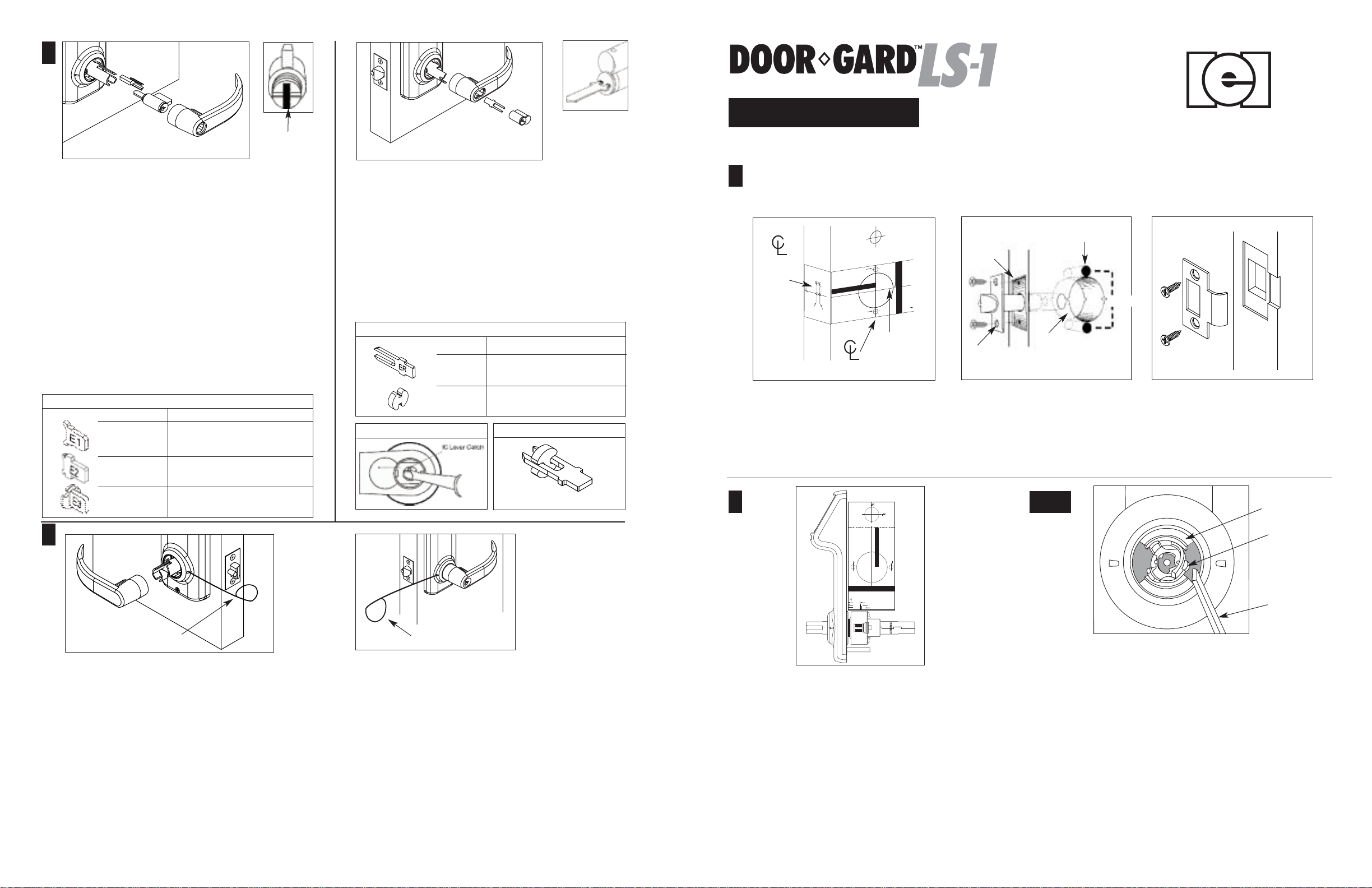
Conventional Cylinder (Figure A)
Outside Lever
1. Tailpiece must be in a vertical position in cylinder. (Fig. A1)
2. Insert cylinder in lever.
3. Press cylinder retainer into lever until flush with base of lever.
4. Align lever catch to face latch front (see Fig. 6).
5. Turn key in cylinder 45° in either direction.
6. Slide lever on tube until it stops at the lever catch.
7. Slightly wiggle and push until lever engages lever catch
and connector.
Conventional Tailpieces For the Door Gard LS-1
Part No. For
LS1P-TLS IEI Cylinders
LS1P-TIL Ilco Cylinders
B
IC Core Cylinder
horizontal position
IC Core Cylinder (Figure B)
Installing IC Core
1. Push lever on door in horizontal position until secure.
2. Insert control key (marked with a “C”) into IC core and
turn clockwise.
3. Insert tailpiece (See char t below.) into core. (Fig. B1)
4. With control key in core, insert core fully into lock.
5. Turn control key 15° to lock cylinder in place.
Remove control key.
I.C. Tailpieces For the Door Gard LS-1
Part No. For
LS1P-TIC7 7 pin IC Core Cylinder
Tailpiece in
LS1P-TICS Spacer to convert 7 pin tailpiece
To Remove IC Core Lever Handle
for use with 6 pin ic core.
Correct Orientation of Spacer
Installation Instructions
1
A
Of
Door
Edge
1-3/4"
(44 mm)
or 1-3/8"
(35 mm)
Door
Thickness
A. Affix paper template to door
and follow template instructions in preparing door.
Note: See template for measurements.
Vertical
Of
Lever
Mark
Height
Line
B
Mortise
Area
Latch
B. Install latch.
5/16" Hole
2-1/8" Hole
©2001 INTERNATIONALELECTRONICS, INC.
427 TURNPIKE STREET,CANTON, MA 02021
(781) 821-0734 • www.ieib.com
FAX INFO CENTER: (781) 821-0734
REFER TO DOC. #6058003 FOR CUT-SHEET
REFER TO DOC. #6058004 FOR PROGRAMMING MANUAL
REFER TO DOC. #6058005 FOR INSTALLATION INSTRUCTIONS
REFER TO DOC. #6108004 FOR INSTALLATION TEMPLATE
C
2-3/4"
C. Install strike.
LS1P-TSG Schlage Cylinders
9
Removal Tool
9A
Removal Tool
Removal of Levers
Inside Lever
1. Insert lever removal tool in slot. (Fig. 9)
2. Depress lever catch and pull lever to remove.
Warranty — International Electronics Incorporated (IEI) warrants its products to be free from defects in material and workmanship, when they have been installed
in accordance with the manufacturers instructions, and have not been modified or tampered with. IEI does not assume any responsibility for damage or injury to
person or property due to improper care, storage handling, abuse, misuse, normal wear and tear, or an act of God. IEI's sole responsibility is limited to the repair
(at IEIs option) or the replacement of the defective product or part when sent to IEIs facility (freight and insurance charges prepaid), after obtaining IEI's Return
Merchandise Authorization. IEI will not be liable to the purchaser or any one else for incidental or consequential damages arising from any defect in, or malfunction
of, its products.This warranty shall expire two years after shipping date for Prox. Pad Keypads. Except as stated above, IEI makes no warranties, either expressed or
implied, as to any matter whatsoever, including, without limitation to, the condition of its products, their merchantability, or fitness for any particular application.
©2002 International Electronics, Inc. • 427 Turnpike Street, Canton, MA 02021
(800) 343-9502 • Fax Info center: (781) 821-0734 • www.ieib.com
Outside Lever
1. Insert key into cylinder and turn 45° in either direction.
2. Insert lever removal tool in slot. (Fig. 9A)
3. Depress lever catch and pull lever to remove.
2
1. Locks are factory assembled with a split spacer ring for
1-3/4" door thickness, (when lock chassis is firmly against ring.)
2. Locks can be adjusted for 1-5/8" to 1-7/8" door thickness.
Before installation, use door thickness gauge on template
(as shown), to check lock chassis position. Center of latch retractor
should align with mark on gauge for appropriate door thickness.
3. If chassis is not on center, screw chassis in or out to align with
mark. If adjusting for doors thinner than 1-3/4" thickness, split
spacer must be removed. Check that lever engages lever catch
before installation.
4. Make sure to adjust for correct door thickness.
2A
Spindle
Lever Catch
Screw Driver
1. To adjust lockset for desired door thickness, turn lock chassis in
the direction to adjust for narrow or thick doors. (For narrow
doors, remove split spacer ring.) It may be necessary to depress
the lever catch on spindle in order to rotate the chassis and spindle.
2. Using a standard screwdriver depress lever catch to clear spindle
support collar while turning lock chassis. Turn spindle to adjust
for correct door thickness.
3. Once lock is adjusted for door thickness, install exterior lever and
check that lever engages lever catch before completing lock
installation. Lever should snap securely into place with no play.
If lever wobbles or does not engage with catch, turn spindle until
lever snaps into place.
4. Complete lockset installation.
Doc #6058004 Rev. 2.0
1 of 4
Page 2
Installation Instructions
3
Tube
Wires with
connectors
Lever should
snap securely
into place
with no play.
3/4”
Hole
Raceway
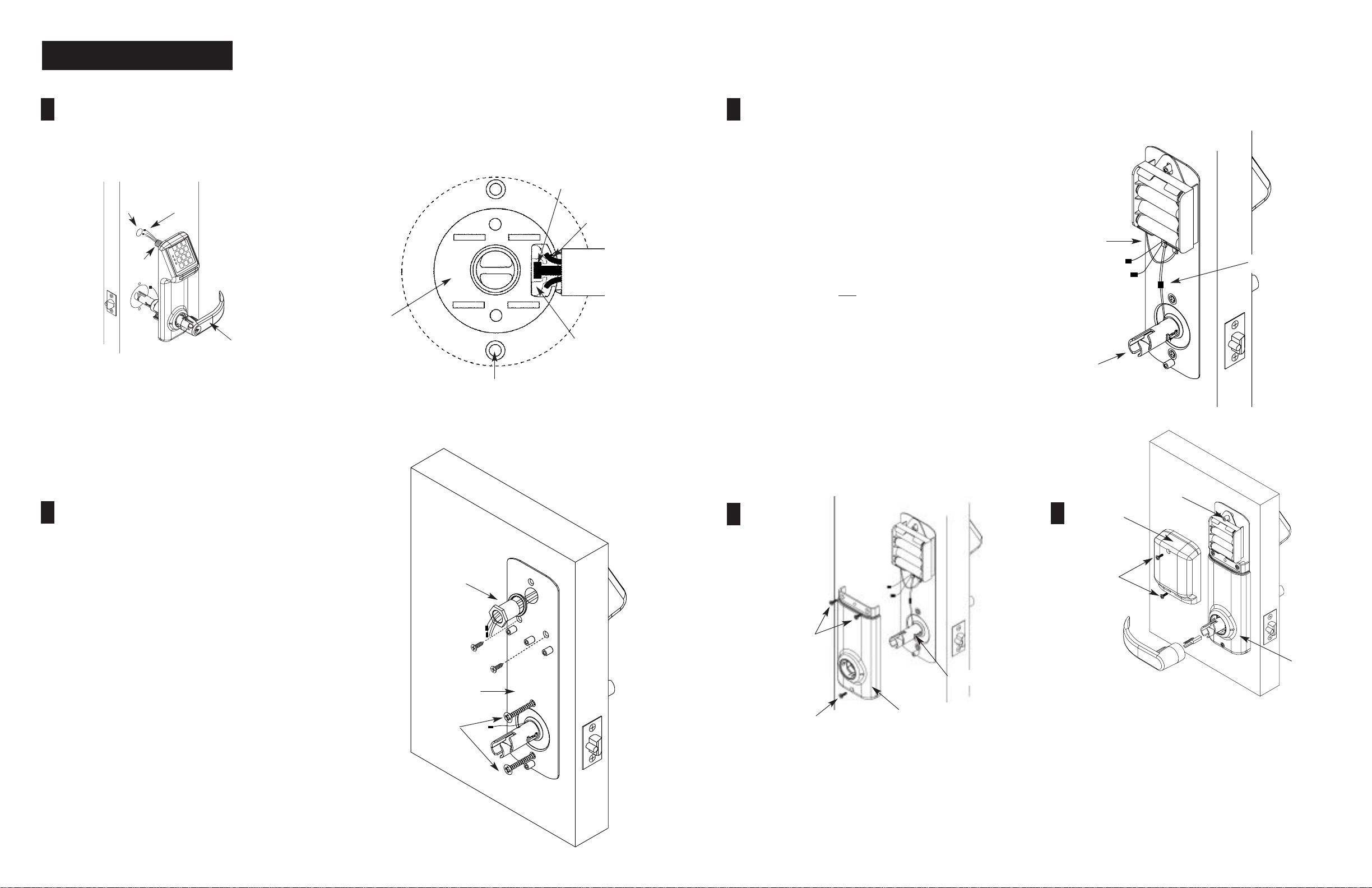
Pass the wires and connectors through the 3/4" hole, then mount
the exterior housing through door preparation. Make sure that the
lock chassis and latch are properly engaged as shown.
(See Fig. 2A)
Figure 2A
Lock Housing
Posts
Latch Tail
Latch
Retractor
Prongs
5
Note: It is recommended to use only alkaline batteries, due to predetermined
power settings in the lock.
Insert 4 AA batteries into battery holder. (Note polarity.)
Note:All wire pairs are color coded to connect with like colored pairs.
1. Connect the grey/red wires from the raceway to the
grey/red wires from the lever tube.
2. Connect the red/black wires from the raceway to
the red/black wires from the battery pack. The four
remaining wires are only
switch, as well as the request to exit (REX) function.
(See the programming manual for details.)
3. Place the battery holder over the center grooved stud.
Note:The fork,located on the bottom of the battery holder will clear
the lower inside housing.
4. When properly aligned, push down on the battery
holder assembly, engaging the upper part of the hole
into the groove of the center stud. This will connect the
lower fork with the center post, giving a very secure fit.
for the optional door position
Red/Black
Grey/Red
Lever Tube
4
1. Remove screw from Battery Cover to access backplate.
2. Feed the wires and connectors through the backplate and
raceway nut. Install lock washer on the raceway nut.
3. While holding the interior backplate in position, loosely
install the two thru-bolts.
4. Tighten the raceway nut on the raceway tube that passes
through the door using a crescent or 7/8" socket wrench.
When this connection is tight, secure the thru-bolts.
5. Install two screws to the backplate to the door (wooden door
application). The two predrilled holes on the backplate are
located below the raceway nut.
Raceway Nut
Interior Backplate
Thru-bolts
6
Brass #8 Screws
Lever Catch
Finished #8 Screw
1. Slide the inside lower housing over the lever tube until it has
passed over the lever catch. Make sure the four remaining
wires (if not used) are properly placed so they are not
pinched by the lower housing.
2. Fasten with two brass #8 screws. Once secure, fasten the
finished #8 screw at the bottom.
Inside Lower Housing
Center
Grooved Stud
7
Battery Cover
#8 Screws
Inside Lower
Housing
PUSH ALL EXCESS WIRE LENGTHS DOWN THROUGH THE
OPENING AT THE TOP OF THE INSIDE LOWER HOUSING.
1. Attach the battery cover with two finished #8 screws.
Battery cover has a lip which engages the lower inside
housing, it is important that this lip be seated properly to
insure correct alignment.
2. Insert cylinder retainer into lever until flush with base of lever.
3. Push level on door in horizontal position until secure.
2 of 4
3 of 4
 Loading...