

Linear LPX1700 Owner's Manual
INSTALLATION AND
OWNER’S MANUAL
LEADER + 1
Model LPX1700 Series - Heavy Duty
Vehicular Slide Gate Operator
PROVEN
CGA2K™
TECHNOLOGY!
Serial #:
Date Installed:
Your Dealer:
As of date of manufacture meets
all ANSI/UL 325 Safety
Requirements for Vehicu lar ga te
operators.
107063
READ THIS MANUAL
CAREFULLY BEFORE
INSTALLATION OR USE
SAVE THESE INSTRUCTIONS
2
TABLE OF CONTENTS
Pre-Installation Notes........................................................ 3
Operator Class Designation ......................................... 3
Section A: Gate System Design/Installation........... 4 & 5
Section B: Preparing the Site .......................................... 6
The Concrete Operator Pad.......................................... 6
Electrical Power Requirements ................................... 6
Placing the Vehicle Detector Loops ............................ 7
Section C: Installing the Operator .................................. 8
Operator Mounting Bracket .......................................... 8
Placing the LPX1700 ..................................................... 8
Attaching the Chain Bracket ........................................ 9
Electrical Power Connections ......................................9
Controls & Accessory Devices Wiring....................... 10
Wiring a 3 Button Station ............................................ 10
Bi-Parting Application (Master/Slave) ........................ 10
Optional Photoelectric Thru Beam Sensor ................ 11
Optional Photoelectric Retro-Reflective Sensor .......12
Optional Electric Edge Sensor .................................... 13
Wiring Loop Detectors ...............................................14
Wiring a Radio Receiver ............................................. 14
Setting the Switch Selectable Options ...................... 15
Open / Close Push Button Enable / Disable.............. 15
Left or Right Hand Installations ................................. 15
Normally Open / Normally Closed Stop..................... 16
Pre-Move Delay / Alarm-In-Motion Setting................ 16
Bi-Parting (Master/Slave, Primary/Secondary) ......... 16
Initial Setting of the Limit Switches........................... 16
Initial Setting of the Obstruction Detection .............. 17
Timer-To-Close Setting............................................... 17
Auto Re-Close Setting ................................................ 17
Section D: Starting the Operator .................................. 18
Indicator Lamps........................................................... 18
Final Setting of Limit Switches .................................. 18
Final Setting the Close Timer..................................... 18
Final Setting - Obstruction Detection........................ 18
Testing the Operator Lock.......................................... 19
Maximum Run Timer ................................................... 19
Final Setting - Bi-Parting Installation ....................... 19
Testing the Loop Detectors /Aux. Equipment .......... 19
Terminal Strip Reference Chart .........................20 & 21
Section E: End User Instructions .................................. 22
Operational Guide for the End User .......................... 23
Manual Operation of Gate........................................... 25
Safety Guide for the End User ...........................24 & 25
Maintenance Guide ..................................................... 26
Exploded View and Parts Listing............................... 26
Wiring Diagram............................................................ 27
Technical Specifications and Warranty ........................ 28
WARNING HIGH VOLTAGE
Figure 1
ONLY A QUALIFIED TECHNICIAN SHOULD SERVICE THIS GATE OPERATOR
PERIODICALLY TEST SENSITIVITY OF OVERLOAD *** READ MANUAL ***
LOG DATE OVERLOAD TEST
DATE TESTED DATE TESTED DATE TESTED DATE TESTED
READ THESE STATEMENTS CAREFULLY AND FOLLOW THE
INSTRUCTIONS CLOSELY.
The Warning and Caution boxes throughout this manual are there to protect you and
your equipment. Pay close attention to these boxes as you follow the manual.
DATES OPERATOR
SERVICED
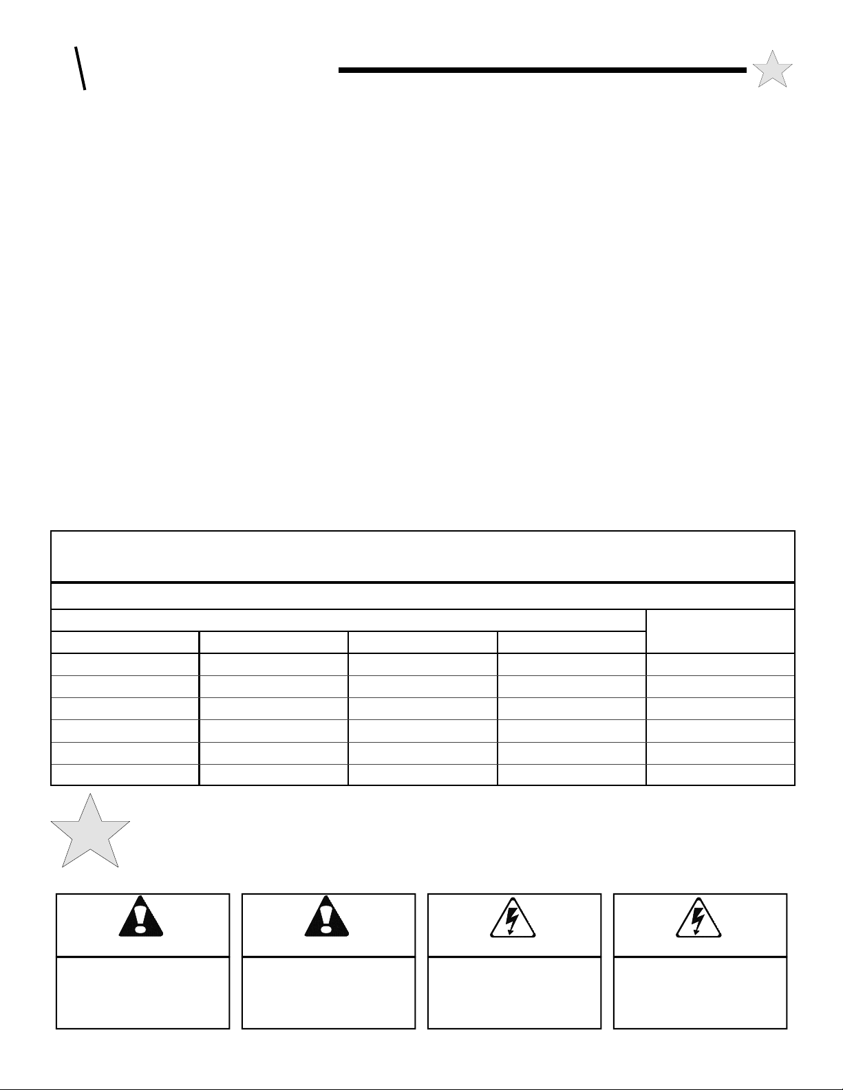
WARNING
Indicates a MECHANICAL
hazard of INJURY OR
DEATH. Gives instructions
to avoid the hazard.
CAUTION
Indicates a MECHANICAL hazard
of DAMAGE to your gate, gate
operator, or equipment. Gives
instructions to avoid the hazard.
WARNING
Indicates an ELECTRICAL
hazard of INJURY OR
DEATH. Gives instructions
to avoid the hazard.
CAUTION
Indicates an ELECTRICAL hazard
of DAMAGE to your gate, gate
operator, or equipment. Gives
instructions to avoid the hazard.

The LPX1700 Vehicular Gate Operator will provide convenience and
assurance to the ultimate users for many years. It is ruggedly built of
the finest materials and has been thoroughly inspected and tested at the
factory. It has many features that will aid in the installation and testing
of the complete gate system. The LPX1700 is certified to comply with
the ANSI / UL Standard for Safety 325.
NOTICE - BEFORE ATTEMPTING INSTALLATION,
READ THIS MANUAL CAREFULLY SO YOU WILL BE
THOROUGHLY FAMILIAR WITH THE FEATURES OF THE
LPX1700
AND ITS PROPER INSTALLATION PROCEDURES.
The LPX1700 slide gate operator (models without suffix or with suffix
“S” only) is designated a Class I Residential Vehicular Slide Gate
Operator and is intended to operate a vehicular slide gate installed on a
residential home, maximum of four single families in the dwelling, or a
garage or parking area associated with such a home. The LPX1700
vehicular gate operator (again models without suffix or with suffix “S”
only) is also designated as a Class II Vehicular Slide Gate Operator for
use in a commercial location or multi-family home. The LPX1700
vehicular gate operator (all models) is also designated as a Class III
(industrial location not intended to service the general public); and IV
(secure or restricted access locations, i.e. airports and prisons). THE
LPX1700 (with appropriate suffix) MAY BE USED IN ANY
CLASS LOCATION.
Because the LPX1700 (as well as gate operators sold by other
manufacturers) is designed to start and move gates weighing as much as
1700 pounds, or more, the LPX1700 is capable of producing high levels
of force. It is important in the design of the total gate system that
designers, installers and users be aware of the hazards that may be
associated with the IMPROPER design, installation and use of
vehicular gate systems and gate operators.
The gate operator is only one part of a complete automatic gate
operating system. As each location and usage is different, a properly
designed system will include all applicable safety devices.
As the designer and installer of the GATE SYSTEM, you must
advise the purchaser on the proper use of the gate system.
The LPX1700 has exclusive Allstar Gate System Technology that
provides several features to help reduce the hazards of your gate
system.
Built-In Overload Detector Sensing System
The LPX1700 has a built-in "overload detector" that can help reduce
the hazards of your gate system. This device, however, must not be
considered as the primary defense system. Consider all available
options (electric leading edges, photoelectric sensors, protective screen
mesh, etc) to eliminate hazards in your gate system design.
The LPX1700’s built-in overload detector will activate if there is an
abrupt slow down in the speed of the gate operator (the operator has
detected an obstruction in its path). A second detection of an
obstruction before the gate reaches the Open or Close limit will result in
the operator going into Alarm Mode. The alarm continues to sound
warning until a fixed wire input is activated or five (5) minutes pass.
The overload detection point is an adjustable setting that must be
determined at the time of installation. This setting must be tested
periodically to ensure proper operation. Diligent maintenance of the
gate hinges and hardware will assure the most responsive operation of
the overload detector. See pages 17, 18, and 25.
ADVISE THE PURCHASER TO CHECK THE SENSITIVITY OF
THE OVERLOAD PERIODICALLY AND, AFTER REMOVING
THE CONTROL BOX COVER, LOG THE DATE TESTED ON THE
LOG LOCATED ON PAGE 2 OF THIS MANUAL (See Fig. 1, pg. 2).
PRE-INSTALLATION NOTES
3
Connections for External Entrapment Prevention Sensors
Because all gate system installations are different, the LPX1700 motor
control board terminal connections provides independent connections
for Open and Close non-contact (photoelectric) and contact (edge)
sensors. In this way a photoelectric sensor could be utilized to guard
the gate area when closing and an edge sensor could provide the
protection when opening. Depending on the particular application a
combination contact and non-contact sensor protection system for the
open and close directions may provide more effective entrapment
protection than a single device for both directions. See pages 4, 5, 11,
12, 13, 21, 25, and 26.
NOTICE - THE IMPORTANT SAFEGUARDS AND
INSTRUCTIONS IN THIS MANUAL CANNOT COVER ALL
POSSIBLE CONDITIONS AND SITUATIONS WHICH MAY
OCCUR DURING ITS USE, IT MUST BE UNDERSTOOD THAT
COMMON SENSE AND CAUTION MUST BE EXERCISED BY THE
PERSON(S) INSTALLING, MAINTAINING, AND OPERATING THE
EQUIPMENT DESCRIBED HEREIN. DO NOT USE THIS
EQUIPMENT FOR OTHER THAN ITS INTENDED PURPOSE -
OPERATING A VEHICULAR SLIDE GATE.
Audio Alarm and Safe Secure™ Open/Close Push Button Enableon-Alarm Only (Patent No. 6,611,205)
The LPX1700’s audio alarm sounds when a second occurrence of the
built-in overload activation is registered before an end limit (open or
close) is reached. The Safe Secure™ Open/Close Push Button Enableon-Alarm Only feature can be set to provide an accessible control
station whose Open and Close inputs are functional in an emergency
situation only. See pages 17, 19, 24, and 26. Diligent maintenance of
the gate rollers and track will avoid nuisance operation of the overload
detector and thereby avoid nuisance operation of the audio alarm.
SMART™ Self adjusting MAximum Run Timer
The LPX1700 has a Self adjusting MAximum Run Timer, SMART™ .
The amount of time for the first few cycles of operation are registered
and averaged within the motor controller circuitry. After the first few
initial cycles, if the gate is activated and no other command is given or
an end limit (open or close) is not reached in the previously counted
cycle time plus approximately 2 seconds, the operator will be turned
off. See page 19.
Fail Secure Lock Mechanism: For the utmost in security, the
LPX1700 models are equipped with a Fail Secure operator locking
mechanism. The lock is active whenever the gate is not moving and
must be released via the integral Solenoid Lock Lever to manually
move the gate. See Page 24, Manual Operation.
Auto Re-Close : Enables an automatic continuation of the closure of
the gate from a partially closed position when the close movement was
interrupted by a non-contact (photoelectric) sensor or contact (edge)
sensor input and the sensor is then cleared. Also allows for an
automatic continuation of the opening movement from a partially open
position if the open movement was interrupted by a non-contact
(photoelectric) sensor and the sensor is cleared. See page 17.
Built-In Three Button Control Station: For ease of initial set-up and
maintenance service, the operator’s motor control board features Open,
Close, and Stop buttons on the board surface.
OTHER FEATURES
Auto Close Timer: Adjustable from 2 to 60 seconds, provides an
automatic closure of the gate from the full open position. See page 17.
Diagnostic LEDs on the Motor Controller Board: Provides a visual
indication of the status of the gate system operation. See page 18.
Built-In Free Exit and Reversing Loop Detector Sockets: Two loop
detector sockets are built-in and pre-wired to the operator's control
system. See pages 7, 14, and 19.
4
A: GATE SYSTEM DESIGN & INSTALLATION
TO REDUCE THE RISK OF SEVERE
INJURY OR DEATH: READ AND FOLLOW
WARNING!
ALL INSTALLATION INSTRUCTIONS AND
GATE SYSTEM DESIGN PARAMETERS!
GATE SYSTEM DESIGN AND INSTALLATION
SAFETY CHECK LIST:
• The LPX1700 operator may be installed on a Class I, II, III, or IV
Vehicular Slide Gate. See page 3 for an explanation of the different
Class locations. See the last page of this manual for the operator
specifications (voltage, maximum gate weight & length etc.).
• Make sure that the gate moves freely, all rollers are in good working
order, the gate does not bind in any manner and the gate area is clean
and free of irregularities. DO NOT INSTALL THE OPERATOR
UNTIL ALL GATE PROBLEMS HAVE BEEN CORRECTED.
• Do not increase the built-in overload detector adjustment to
compensate for a poorly working gate. A well maintained gate will
ensure easy manual operation (if needed) and maximum operator
obstruction sensitivity.
• Install the operator on the inside of the property/fence line. DO
NOT install an operator on the public side of the fence line or gate.
• Make sure the gate operating system is placed far enough back from
the road to eliminate traffic backup. The distance from the road, size
of the gate, usage level and gate cycle/speed must be taken into
consideration to eliminate potential hazards.
• The gate must be installed in a location so that enough clearance is
supplied between the gate and any adjacent structures when opening
and closing to reduce the risk of entrapment.
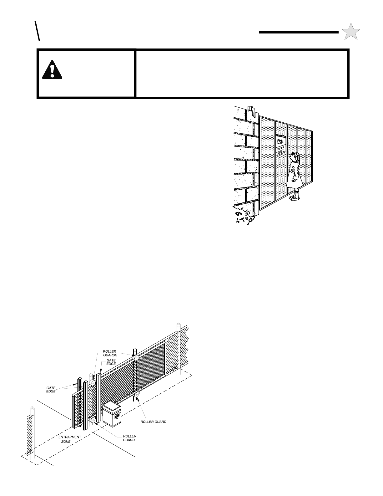
• For ORNAMENTAL “GRILL TYPE” GATES (or any other type of
open gate where a handhold or toehold may be achieved), injuries
may occur when people put arms through the openings or children
106709
Figure 3
104949
Figure 2
“ride” the gate by standing on the bars and holding on to the gate.
THIS POTENTIAL HAZARD CAN BE MINIMIZED BY
INSTALLING A MESH SCREEN ON THE GATE. It is strongly
recommended that the entire gate and adjacent fence area the gate
covers when open be meshed or guarded such that a handhold or
toehold cannot be achieved. At a minimum all openings on a
horizontal slide gate must be guarded or screened from the bottom of
the gate to a minimum of 4 feet above the ground to prevent a 2-1/4
inch (57.15 mm) sphere from passing through the openings
anywhere in the gate, and in that portion of the fence the gate covers
when in the open position. See Figure 2.
• All LPX1700 gate operators are VEHICULAR GATE
OPERATORS and as such are NOT INTENDED FOR
PEDESTRIAN traffic. In installations where pedestrian passage
through the fence is necessary, install a pedestrian access opening.
The pedestrian access opening shall be designed to promote
pedestrian usage. Locate the vehicular gate and the pedestrian
access opening such that persons will not come into contact with the
vehicular gate during the entire path of travel of the vehicular gate.
See page 25 for additional information.
• Install leading edge detectors and/or photocells in your design to
protect system entrapment zones. TYMETAL can provide these
products for incorporation in your gate system design.
• Use the illustration at left (Figure 3) and the information and
diagrams on pages 11, 12, and 13 to minimize the risk of injury in
your design of the swing gate operator system. IDENTIFY THE
ENTRAPMENT ZONES AND PINCH POINT AREAS IN YOUR
GATE. Design the gate installation to minimize the risk of
entrapment in these areas. Install additional safety equipment such
as four wire edges and photocells to further minimize risk. All
entrapment zones are required to be protected.
• Entrapment Zones: Design in personal entrapment protection
devices to protect people from entrapment in the zones shown in
Figure 3 at left and the information and diagrams on pages 11, 12,
and 13. Install vertical posts with gate edges attached on both sides
of the gate to prevent body entrapment.
A: GATE SYSTEM DESIGN & INSTALLATION
5
ALL APPROPRIATE SAFETY FEATURES MUST BE
INCORPORATED INTO YOUR GATE SYSTEM.
• Pinch Points: Use protective measures (guards, padded edges, etc.)
to protect people from the pinch points shown in Figure 3 at left and
the information and diagrams on pages 11, 12, and 13. Attach
roller guards in cantilevered gate systems to minimize the risk of
hands being caught between the top of the gate and the roller.
• DO NOT consider the built-in overload detector as the primary
defense system. Consider all options in the gate system design.
• DO NOT connect any auxiliary equipment to the LPX1700 operator
(detectors, card readers, etc.) until the gate operator and all its
functions are fully tested. Only connect one device at a time and
ensure its proper function(s) before moving on to the next device.
• DO NOT locate any control device (key switch, switch, key pad,
card reader, etc.) in a position where it may be activated by a person
reaching through the gate or while touching the gate in any manner.
Locate all control devices a minimum of 10 feet from the gate when
opened or closed.
• Outdoor or easily accessible controls must be of the security type to
prevent unauthorized use of the system.
• Install all devices that will Open, Close or Stop the gate in such a
manner that THE GATE WILL BE IN FULL VIEW WHEN THE
DEVICE IS OPERATED.
• Before activating the "timer to close" option of the LPX1700,
ENSURE THE PERSONAL ENTRAPMENT PROTECTION
DEVICES (operator reversing feature, edges, photocells) ARE
OPERATING and install VEHICLE DETECTOR LOOPS AND
VEHICLE DETECTORS for protection of user vehicles. Read the
manual for information on the installation of these devices. IF
VEHICLE DETECTOR LOOPS HAVE BEEN INSTALLED TO
PREVENT THE GATE FROM CLOSING ON A VEHICLE,
INSTRUCT THE USER TO PERIODICALLY CHECK THE
OPERATION OF THE DETECTORS.
• USE EXTREME CAUTION WHEN WORKING NEAR THE
BELTS AND PULLEYS when the operator cover is removed.
Apply power to the operator only when instructed to do so.
• When the outer cover of the LPX1700 and the handy box covers are
removed, high voltage will be exposed. EVEN IF THE RED
POWER LIGHT IS NOT LIGHTED, HIGH VOLTAGE AC IS
STILL PRESENT. NEVER LEAVE THE INSTALLATION WITH
THE HANDY BOX OR OUTER COVERS REMOVED.
• ALWAYS TURN OFF THE POWER BEFORE ATTEMPTING
SERVICE OF EITHER THE ELECTRICAL OR MECHANICAL
SYSTEMS.
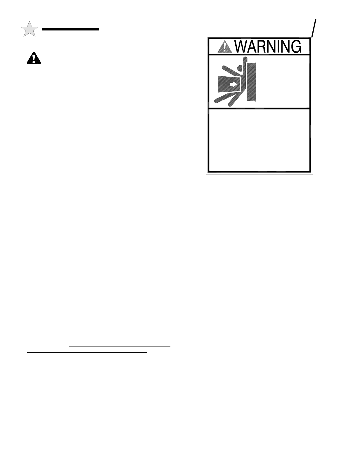
• SECURELY ATTACH THE WARNING SIGNS provided with the
LPX1700 on the gate (one on the outside and one on the inside)
where they can be seen by persons in the area of the gate to alert
them of automatic gate operation. (If the user refuses to have the
warning signs installed, it is recommended that you note this on your
records and have the user sign a disclaimer.) See Figure 4.
MOVING GATE
CAN CAUSE
SERIOUS
INJURY OR
DEATH
KEEP CLEAR !
Gate May Move at Any Time.
Do not allow children to play
in gate area or operate gate.
Operate gate only when gate
area is in sight and free of
people and obstructions.
Figure 4
AS THE INSTALLER YOU ARE RESPONSIBLE FOR:
1 ASSURING THAT THE GATE AND OPERATOR SYSTEM,
WHEN FULLY INSTALLED AND OPERABLE, COMPLIES
WITH ALL APPLICABLE REQUIREMENTS OF UL325:
STANDARD FOR SAFETY FOR DOOR, DRAPERY, GATE,
LOUVER AND WINDOW OPERATORS AND SYSTEMS.
2 ASSURING THAT THE OWNER/END USER OF THE
SYSTEM UNDERSTANDS ITS BASIC OPERATION AND
SAFETY FEATURES. IN PARTICULAR, BE SURE THE
OWNER/END USER UNDERSTANDS THE LOCATION
AND OPERATION OF A MANUAL DISCONNECT
(WHERE PROVIDED) OR HOW TO OPERATE THE
GATE .
3 YOU ALSO HAVE THE PRIMARY RESPONSIBILITY OF
INSURING THAT ALL POSSIBLE OPERATIONAL
HAZARDS HAVE BEEN CONSIDERED AND
ELIMINATED. YOU MUST ADVISE AND WARN THE
PURCHASER AND THE ULTIMATE USER OF ANY
HAZARDS THAT YOU HAVE NOT BEEN ABLE TO
ELIMINATE.
4 POINTING OUT TO THE OWNER/END USER OF THE
GATE SYSTEM THAT CHILDREN OR PETS ARE NOT
ALLOWED TO PLAY ON OR NEAR THE GATE, FENCE
OR ANY PART OF THE SYSTEM, AND THAT THE
SAFETY INSTRUCTIONS SUPPLIED WITH THIS
OPERATOR AND THEIR IMPLEMENTATION ARE THE
RESPONSIBILITY OF THE OWNER/END USER.
5 LEAVING THE INSTALLATION AND MAINTENANCE
MANUAL FOR THIS OPERATOR AS WELL AS ANY
ADDITIONAL SAFETY INFORMATION SUPPLIED WITH
THIS OPERATOR OR OTHER COMPONENTS OF THE
GATE SYSTEM WITH THE OWNER/END USER.
6 NOT PLACING IN SERVICE THIS OPERATOR IF YOU
HAVE ANY QUESTIONS ABOUT THE SAFETY OF THE
GATE OPERATING SYSTEM. CONSULT THE
OPERATOR MANUFACTURER.
104880
2'-0"
6
B: PREPARING THE SITE
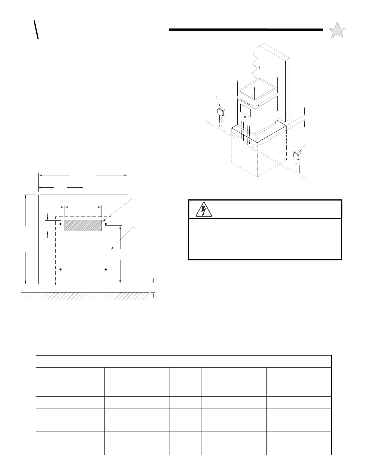
THE CONCRETE OPERATOR PAD
Installation requires the presence of a suitable concrete pad as a base for
the operator. The dimensions of this pad should be at least 12" greater
than the dimensional pattern of the operator mounting holes. The top of
the pad should be 7" above grade to raise the operator above any
standing water, while the depth of the pad below grade is dependent on
the soil conditions at the installation site and the size of the gate. The
LPX1700 cover is 24" high and is removed by lifting it vertically off
the operator. THE SITE FOR THE OPERATOR SHOULD BE
CHOSEN WITH AT LEAST 24" OF CLEARANCE ABOVE THE
TOP OF THE UNIT.
If no suitable concrete base exists, a pad must be poured. After
completing the gate installation, place the operator pad at the
appropriate location as described in Figures 5 and 6. Consult local
building codes for depth of base. Typical depths range from 24” to 36”.
In either case, if vehicles are going to be operated in the vicinity of the
operator, consider installation of protective bollards in front of the
operator.
MINIMUM
1'-0"
TARGET AREA FOR
CONDUIT PLACEMENT
10"
IN CONCRETE PAD
ALLOW 24"
CLEARANCE ABOVE
OPERATOR FOR
COVER REMOVAL
TERMINAL BOX
LOW VOLTAGE
CONTROL WIRING
CONDUIT
DEPTH OF PAD
DEPENDENT ON
LOCAL CODES.
Figure 5: Pad Configuration
WARNING!
GATE
HIGH VOLTAGE
HIGH VOLTAGE
AC POWER
POWER CONDUIT
7" ABOVE GRADE
(MINIMUM)
WEATHERPROOF/LOCKABLE
POWER SWITCH BOX
(OPTIONAL - BY OTHERS)
115 VAC
CONDUIT
3"
OPERATOR
2'-0"
MINIMUM
16"
GATE FRAME
ELECTRICAL POWER REQUIREMENTS
Figure 6: Operator Footprint
2-1/4"
MEASURE
FROM VERTICAL
GATE MEMBER
The LPX1700 Series operators have been designed and constructed
for use with voltages from 115 Volts AC to 460 Volts AC, in single
LPX1700
Unit Voltage
& Phase
120 V, 1P N/A 90 Feet 150 Feet 240 Feet 380 Feet 600 Feet 970 Feet
#16 Ga.
N/A
WIRE SIZE and RECOMMENDED MAXIMUM RUN LENGHTS
#14 Ga. #12 Ga. #10 Ga. #8 Ga. #6 Ga. #4 Ga. #2 Ga.
AVOID ELECTROCUTION:
Do not route low voltage wires in the same conduit
as high voltage wires. Follow all local electrical
codes or the National Electric Code.
or three phase. Check the operator nameplate label for the proper
voltage and phase. The application of an improper input voltage or
phase will result in catastrophic failure to the internal electrical
components.
The operator voltage service is to originate from a circuit breaker
protected panel of the appropriate amperage (again reference the
operator nameplate label). In installations with more than one operator,
each operator must have a separate service from the breaker panel.
Powering multiple operators from the same service can result in having
to "de-sensitize" the obstruction sensing adjustment to prevent one
operator from overloading the other. The electrical hookup is made in
the junction box located in the left front corner of the frame, see Figure
7, Page 7. For conduit placement see Figures 5, 6, & 7. The AWG
wire size for the electrical service depends on the distance of the
208 V, 1P 200 Feet 315 Feet 500 Feet 775 Feet 1250 Feet 1950 Feet 3000 Feet
240 V, 1P 225 Feet 360 Feet 575 Feet 900 Feet 1450 Feet 2200 Feet >2200 Feet
208 V, 3P 425 Feet 700 Feet 1075 Feet 1700 Feet 2500 Feet >2500 Feet >2500 Feet
240 V, 3P 525 Feet 825 Feet 1325 Feet 2100 Feet >2500 Feet >2500 Feet >2500 Feet
480 V, 3P 1600 Feet 2500 Feet >2500 Feet >2500 Feet >2500 Feet >2500 Feet >2500 Feet
115 Feet
140 Feet
275 Feet
325 Feet
1000 Feet
B : PREPARING THE SITE
operator from the breaker panel. Refer to the table below to determine the correct wire
size. For distances greater than 1600', it is recommended that your local utility be
contacted to install a service feeder for the installation.
Wiring from external controls such as guard shack, telephone entry, keypad or card
reader systems should be brought to the operator by a conduit separate from the High
Voltage AC electrical hookup. Low voltage control wires MUST NEVER be routed in
the same conduit as the High Voltage AC power wires. For conduit placement see
Figures 5, 6, & 7. Always consult and follow all local electrical codes.
MAKE SURE POWER IS OFF BEFORE WIRING OR SERVICING THE
OPERATOR.
W A R N I N G !
RISK OF ENTRAPMENT
Vehicle detector loops will not detect smaller vehicles such
as motorcycles, golf carts, bicycles, or pedestrians.
Photoelectric detectors, edge detectors and separate
pedestrian access must be installed.
Figure 7:
Service
Conduits
HIGH VOLTAGE
115 VAC LINE
AC LINE
CONNECTION
CONNECTION
BOX
BOX
LOW VOLTAGE
CONDUIT FOR
WIRING AUXILIARY
DEVICES TO
TERMINAL STRIP
GATE
115 VAC
HIGH VOLTAGE
POWER CONDUIT
7
ALTERNATE WIRING
ALTERNATE WIRING
FOR 115 VAC
FOR HIGH VOLTAGE
HIGH VOLTAGE
AC POWER CONDUIT
POWER CONDUIT
WEATHERPROOF/
LOCKABLE
POWER SWITCH
BOX (OPTIONAL)
Figure 8:
Loop
Diagrams
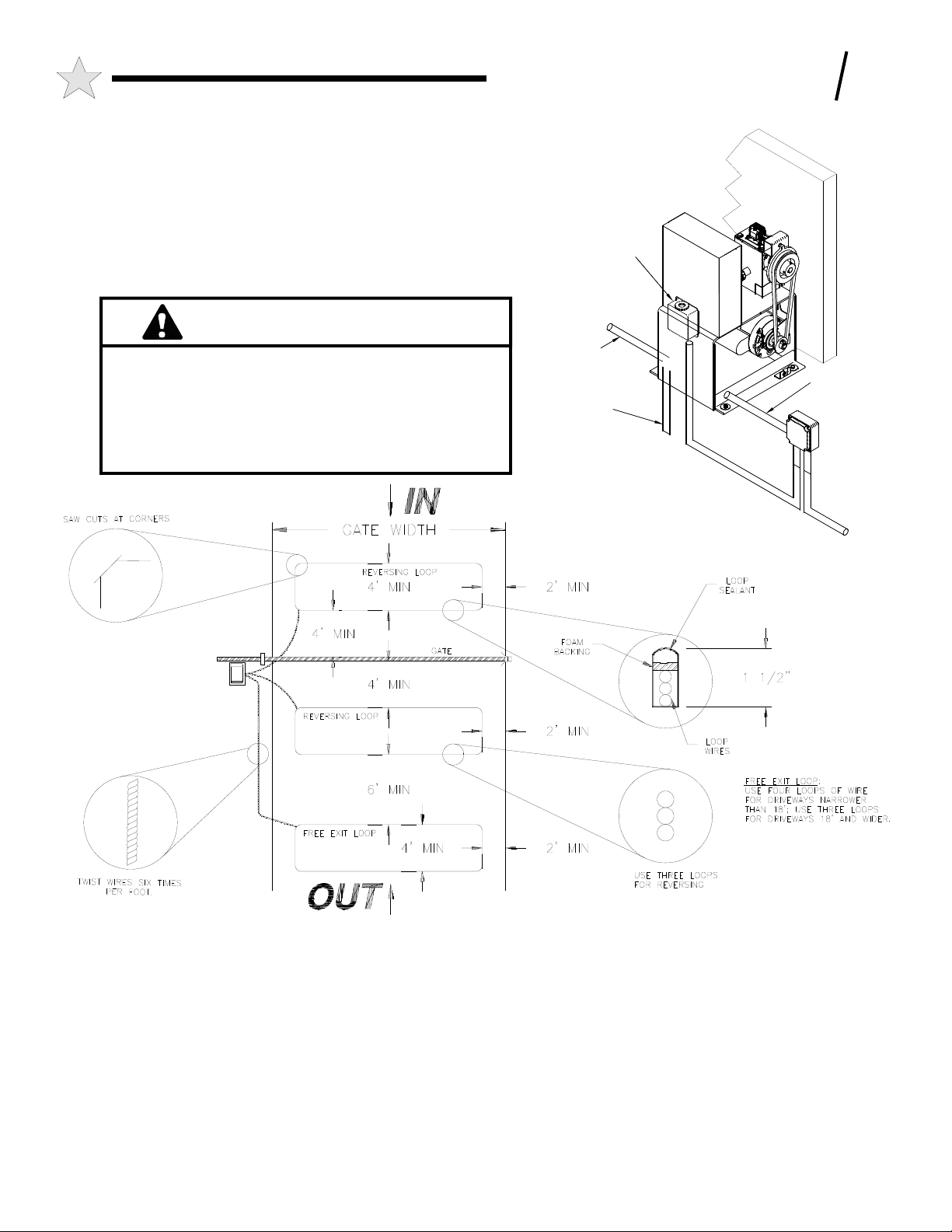
PLACING THE VEHICLE DETECTOR LOOPS
Proper placement of vehicle detector wire loops is critical if the loops
are to provide satisfactory, extended service. The most important
considerations are: 1) Proper wire type and, 2) Good, tight connections
from the loop to the loop terminating connector. When a "Stand
Alone" vehicle detector is used, the detection loop is connected to the
wire harness on the detector itself. (See WIRING VEHICLE
DETECTORS, Page 14.)
The LPX1700 provides for the use of two loop systems: 1) A
"reversing" loop that will prevent the gate from closing on a vehicle
that has stopped in the path of the gate and, 2) A "free exit" loop that
will open the gate by detecting a vehicle which is inside the gated area
and wishes to leave. If "free exit" detection is not desired, this loop
will not be needed. Note the "reversing” loop is normally made up of
two loops connected to one detector. See Figure 8 above.
Two different types of installations will usually be encountered: 1) If
the driveway material is already in place, saw cuts will be needed to
accommodate the loop wires.
2) For loops where the paving material will be installed after the loop
is positioned, it is necessary that the loop wires be placed in Schedule
40 PVC pipe to maintain uniform loop spacing with respect to the
surface of the pavement. The loop should be placed 1.5 inches below
the surface of the pavement and at least 2" above any reinforcing steel
The lead-in wires need not be in PVC, but must have at least six (6)
twists per running foot.

8
B: PREPARING THE SITE
For a saw-cut installation, observe the method recommended in
Figurez8 for the corners. When installing a two-loop reversing system
it is best to bring the twisted lead wires from each loop to the operator
so that the loops may be properly phased. The saw cut must be to a
depth of 1.5 inches, clean and with no sharp corners. After placing the
wires, it is essential that the wires be held tightly in place by the foam
backing and that no voids exist that can collect water which might
freeze and push the loop wires out of the slot. The sealant used should
match the paving material and should not be hard setting. The lead-in
wires must have at least six (6) twists per foot.
NO SPLICES ARE ALLOWED IN THE LOOP OR THE LEAD-IN
WIRE TO THE FIRST JUNCTION BOX Above ground splices may
be used providing the wire is twisted, soldered and moisture sealed.
For best long term results, do not use wire nuts anywhere in the loop
system. For connections to the loop detector, gas tight crimp type
terminals should be used, and soldered if possible.
THE WIRE USED FOR THE LOOPS MUST BE HEAT AND
WATER RESISTANT. CROSS-LINK POLYETHYLENE
INSULATED, TYPE XLPE OR RHW IS BEST. U.S.E. IS ALSO
SATISFACTORY. DO NOT USE PVC INSULATED WIRE. WIRE
SIZE SHOULD BE #16zGA STRANDED OR LARGER.
C: INSTALLING THE OPERATOR
TOOLS REQUIRED
The following tools and materials are required for proper
installation of the operator:
1. Two 3/4" wrenches. (For tightening hex nuts on the
chain take-up bolts.)
2. Chain cutting tool. (For adjusting chain length.)
3. Wire cutter, stripper and crimping tools. (For attaching
accessory equipment to the control box barrier strip.)
4. Standard screwdriver. (For junction box face plate.)
5. Very small standard screw driver. (For adjusting
controller board trimmer potentiometers.)
6. Phillips head screwdriver. (For control box face plate.)
7. Electric arc welder or an electric drill with a 3/8" bit.
(For attaching chain brackets to gate.)
8. Several feet of 18 AWG or 22 AWG insulated multistrand electrical wire. (For attaching accessory
equipment to the control box barrier strip.)
9. Four 1/2" anchor bolts with hex nuts, flat washers and
lock washers. (For attaching the operator to the concrete
pad.) Additional flat washers may be required as
leveling shims (see Page 9).
10. 1/2”, 9/16” & 5/8” wrenches for various fasteners.
UNPACKING CHECKLIST
The following is a check list of the various parts included with the LPX1700 operator:
1. (1) LPX1700 Slide Gate Operator w/Cover
2. (2) Gate Warning Signs
3. (1) Installation Manual
4. (2) End Chain Brackets
5. (1) Chain Take-up Bolt Kit
6. (25 ft) #41 Chain
7. (2) Master Links
C: INSTALLING THE OPERATOR
9
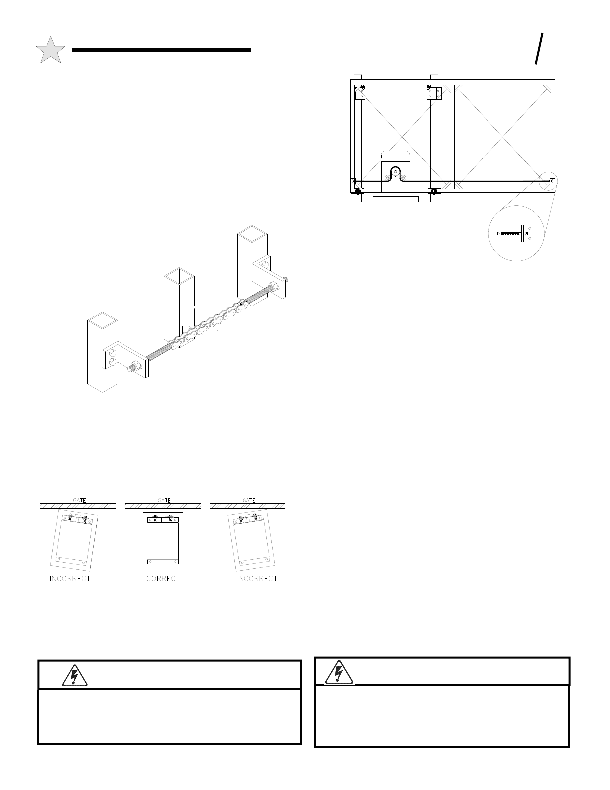
ATTACHING THE CHAIN BRACKETS and
PLACING THE LPX1700 OPERATOR
The chain brackets provided with the LPX1700 operator are mounted
on each end the gate with the centerline of the slot 8" above the top of
the operator pad. You will normally require a welder, or an electric
drill with a 3/8" bit, for attaching the chain brackets to the gate. See
Figures 9 and 10.
From the center of the slot in the bracket, run a string line taught from
one chain mounting bracket to the other. Place the operator on the new
pad or existing concrete base and position the unit so that the string is
centered on the primary drive sprocket, centered on the pad from left to
right, and parallel with the gate frame as shown in Figure 10a. Using
the operator as a template, mark and drill the
appropriate holes for the required anchor bolts
(four [4] ½” anchor bolts are required).
Install the anchor bolts per the bolt
manufacturers instructions.
Re-sit the operator over the
anchor bolts, making
sure the operator
is sitting
level. If
any
corners
of the
operator
are
resting
above
the pad,
place flat washers as shims between the operator and concrete pad
(around the anchor bolts). Place the flat washers, lock washers and nuts
on the anchor bolts and tighten down the operator securely.
Attach one end of the chain to the gate and thread the other end through
the idler pulleys and drive sprocket. Attach the free end to the bracket
on the opposite end of the gate and tension the chain. See Figs. 9 & 10.
Do not over-tension the chain.
Chain Mounting
Bracket
Figure 10:
Chain Configuration
Figure 10a: Parallel Placement
ELECTRICAL POWER CONNECTIONS
Ideally, the conduit containing the hook-up wires should exit the
concrete pad under the operator. There is a 3" gap in the front of the
Chain
Mounting
Bracket
Figure 9: Chain Configuration
bottom plate of the operator provided for this
purpose. Run flexible conduit from the point
where the conduit exits the pad and attach it to the bottom of the High
Voltage AC Line Connection box under the operator’s control box.
Review Figures 5 and 7, pages 6 and 7. If the hook-up exits the pad
external to the operator, there's a 7/8" diameter hole in each side of the
frame near the front of the operator. Connect the conduit to either hole
and cut a small slot in the 1-1/2" high skirt around the base of the cover.
This will allow the cover to fit down flush with the conduit in place.
Review Figure 7, Page 7. Remove the High Voltage AC Line
Connection box face plate. Using the wire nuts provided, attach the
electrical service lead wires to the electrical hook-up wires in the
connection box per the wiring diagram on page 23.
NOTE: The LPX1700 control board comes equipped with a built-in
surge protection which MAY prevent damage to the controller board in
the event of a nearby lightning strike or a surge in the power lines. For
the surge protector to function, and as a general precaution, the operator
must be properly grounded.
ADDITIONAL LIGHTNING PROTECTION
For those areas where a high probability of ground lightning strikes
exists (Florida, Georgia, etc.), additional lightning protection should be
installed in the LPX1700. Although it may not be possible to protect
against all strikes, additional protection will substantially reduce the
occurrence of lightning damage. Industry lightning data indicates that
the most strikes enter an appliance through the power lines. Effective
protection requires that the surge current from the lightning strike be
shunted to ground. This must be done without raising the potential of
the circuitry in the LPX1700, with respect to ground, to the levels that
will damage the solid state circuitry. Lightning strikes generate
enormous currents for very short periods of time. Unfortunately, the
period of time is long enough to damage solid state components and
many times, other components. The key to success is a very low
resistance path from the surge protector to ground for these currents in
addition to a surge protector that will act fast enough to protect the solid
state circuitry. Several manufacturers offer suitable surge protectors.
W A R N I N G !
RISK OF ELECTROCUTION
Do not begin the electrical connection procedures until the
power is turned off at the circuit breaker.
W A R N I N G !
TO REDUCE THE RISK OF DAMAGE DUE TO LIGHTNING,
ENSURE A SOLID GROUND FROM THE LPX1700 GROUND
WIRE IN THE SERVICE ENTRANCE 4 x 4 HANDY BOX TO
THE ELECTRICAL SERVICE GROUND OR TO A EARTH
GROUND STAKE NEAR THE LPX1700.
 Loading...