

Page 1

IEI Max 3
Installation/Programming Manual
Document Number: 6055673
Revision: 1.0
Date: 01/24/07
Page 2

Table of Contents IEI Max 3 Installation/Programming Manual
Table of Contents
Section 1: System Features and Specifications........................................................ 5
1.1 System Features...........................................................................................................................5
1.2 Specifications................................................................................................................................6
1.3 System Defaults............................................................................................................................6
1.4 Max 3 Door Control Module Diagram...........................................................................................7
1.5 Backplane Diagram.......................................................................................................................8
Section 2: Installation................................................................................................... 9
2.1 Check the Packing List..................................................................................................................9
2.2 Mount the Enclosure.....................................................................................................................9
2.3 Ground the Unit...........................................................................................................................10
2.4 Connect the RS-485 Cable from the Module to the Backplane..................................................11
2.5 Connect Additional Modules to the Backplane...........................................................................12
2.6 Wire an Electric Door Lock to the Main Relay of the Max 3 Module.......................................... 13
2.6.1 Installing a Diode to Prevent Electrical Kickback from Lock – DC Locks Only................... 14
2.6.2 Installing an MOV to Prevent Electrical Kickback from Lock – AC Locks Only...................14
2.6.3 Mounting the PowerGard PG-1224-3 Power Supply for Lock Power................................. 15
2.6.4 Wiring the PowerGard PG-1224-3 Power Supply for Lock Power......................................16
2.7 Connect a Secured Series Front End (SSFE) Reader to the Door Control Module...................17
2.8 Connect the Primary Wiegand Front End Reader (IN Reader).................................................. 18
2.9 Connecting a Secondary Wiegand Front End Reader (OUT Reader)........................................19
2.10 Wire a Request to Exit (REX) device and Door Contact...........................................................20
2.11 Wire the Alarm Shunt Relay......................................................................................................21
2.12 Wire the Door Ajar Relay..........................................................................................................22
2.13 Wire the Forced Door Relay......................................................................................................23
2.14 Network the Max 3....................................................................................................................24
2.14.1 Connect the Max 3 Backplane Directly to a PC................................................................ 24
2.14.2 Connect Multiple Backplanes Together.............................................................................25
2.14.3 Connect the SEG-M to the Max 3 (LAN/WAN Connection).............................................. 26
2.14.4 Connecting the SEG-1 to the Max 3 (LAN/WAN Connection).......................................... 27
2.15 Installing a Tamper Switch........................................................................................................28
2.16 Complete Connections Between the 16.5 VAC Transformer and Backplane.......................... 29
2.17 Power up the System................................................................................................................30
Section 3: Programming............................................................................................ 31
3.1 Programming Methods................................................................................................................31
3.2 Entering Program Mode and Changing the Master Code...........................................................32
3.2.1 Entering Program Mode.......................................................................................................32
3.2.2 Changing the Master Code..................................................................................................32
3.2.3 Programming a Supervisor Code........................................................................................32
3.3 Changing the Door Number........................................................................................................33
3.4 Changing the Main Relay Time...................................................................................................33
3.5 Setting the Time and Date..........................................................................................................33
3.6 Programming Users....................................................................................................................34
3.6.1 User Types...........................................................................................................................34
3.6.2 Programming a “Code Only” User.......................................................................................35
3.6.3 Programming “Card Only” Users by Presentation..............................................................35
3.6.4 Programming 26-Bit “Card Only” Users without Presentation.............................................35
Page 2 of 52 Document #: 6055673, Rev 1.0 D1f
Page 3

IEI Max 3 Installation/Programming Manual Table of Contents
3.6.5 Programming “Code AND Card” Users...............................................................................36
3.6.6 Programming “Code or Card” Users....................................................................................36
3.6.7 Programming 26-Bit “Card Only” Users via Batch Entry without Presentation................... 37
3.6.8 Programming Consecutive “Card Only” Users via Batch Entry by Presentation................ 37
3.6.9 Command 50 Quick Program Feature - “Code Only” or “Card Only”..................................37
3.7 Deleting Users.............................................................................................................................38
3.7.1 Delete a Single User............................................................................................................38
3.7.2 Delete a Block of Users.......................................................................................................38
3.8 Programming Extended Unlock Time.........................................................................................39
3.9 Programming Facility Code.........................................................................................................39
3.10 Programming User Lockout......................................................................................................39
3.11 Programming the Door Ajar Output Time.................................................................................40
3.12 Programming the Forced Door Time........................................................................................40
3.13 Using the Default Auto-Unlock Timezone.................................................................................41
3.13.1 Enable/Disable Timezones................................................................................................41
3.13.2 Enable/Disable Auto-Unlock..............................................................................................41
3.13.3 Enable/Disable First-In Auto-Unlock..................................................................................41
3.14 Programming Error Lockout......................................................................................................42
3.14.1 Setting the Error Lockout Threshold..................................................................................42
3.14.2 Setting the Error Lockout Duration....................................................................................42
3.15 Programming Wiegand LED Active State.................................................................................43
3.16 Programming Wiegand Sounder Active State..........................................................................43
3.17 Enable/Disable Control Module Audio Indicators..................................................................... 44
3.18 Reseting System Defaults and Erasing Memory......................................................................45
3.18.1 Resetting the Master Code and System Defaults Only.....................................................45
3.18.2 Erasing Entire Memory/Resetting System Defaults.......................................................... 45
3.18.3 Erasing the Transaction Event Log...................................................................................45
3.19 Programming Daylight Savings Time........................................................................................46
3.19.1 Enabling/Disabling Daylight Savings Time........................................................................46
3.19.2 Selecting Daylight Savings Time Format...........................................................................46
3.20 Programming Options Chart.....................................................................................................47
Section 4: Troubleshooting........................................................................................ 50
4.1 Troubleshooting Chart.................................................................................................................50
4.2 Keypad Self-Test.........................................................................................................................50
4.3 Front End Error Indicators...........................................................................................................50
4.4 Lithium Battery Replacement......................................................................................................51
Document #: 6055673, Rev 1.0 D1f Page 3 of 52
Page 4

List of Tables and Illustrations IEI Max 3 Installation/Programming Manual
List of Tables
Table 1: System Features.......................................................................................................................5
Table 2: Specifications.............................................................................................................................6
Table 3: System Defaults........................................................................................................................6
Table 4: User Types..............................................................................................................................34
Table 5: Control Module Audio Indicators.............................................................................................44
Table 6: Programming Options Chart....................................................................................................47
Table 7: Troubleshooting Chart.............................................................................................................50
Table 8: Front End Error Indicators.......................................................................................................50
List of Illustrations
Figure 1: Max 3 Module Diagram............................................................................................................7
Figure 2: Max 3 Backplane Diagram.......................................................................................................8
Figure 3: Connecting the GND Terminal from Transformer to the Backplane......................................10
Figure 4: RS-485 Connection from Max 3 Module to Backplane..........................................................11
Figure 5: Connecting Additional Modules to the Backplane................................................................. 12
Figure 6: Connecting Diode Across Strike............................................................................................14
Figure 7: Connecting Diode Across Maglock........................................................................................14
Figure 8: Connecting MOV Across Strike..............................................................................................14
Figure 9: Mounting the PG-1224-3 Power Supply................................................................................ 15
Figure 10: Wiring a Maglock to the PG-1224-3 Power Supply............................................................. 16
Figure 11: Wiring an Electric Strike to the PG-1224-3 Power Supply...................................................16
Figure 12: Connect Secured Series Front End to DCM........................................................................17
Figure 13: Connect Primary Wiegand Front End Reader to DCM........................................................18
Figure 14: Connect Secondary Wiegand Front End Reader to DCM...................................................19
Figure 15: Wiring a REX Switch and Door Contacts.............................................................................20
Figure 16: Wiring the Alarm Shunt Relay..............................................................................................21
Figure 17: Wiring the Door Ajar Relay...................................................................................................22
Figure 18: Wiring the Forced Door Relay..............................................................................................23
Figure 19: Wiring Max 3 Backplane to a PC.........................................................................................24
Figure 20: Connecting Multiple Backplanes Together.......................................................................... 25
Figure 21: Connecting the SEG-M to the Max 3...................................................................................26
Figure 22: Connecting the SEG-1 to the Max 3....................................................................................27
Figure 23: Installing a Tamper Switch...................................................................................................28
Figure 24: Completing the Transformer Connections...........................................................................29
Figure 25: Plug on Detachable Keypad.................................................................................................31
Page 4 of 52 Document #: 6055673, Rev 1.0 D1f
Page 5

IEI Max 3 Installation/Programming Manual Section 1: System Features and Specifications
Section 1: System Features and Specifications
The following section outlines the Max 3 features, specifications and default settings.
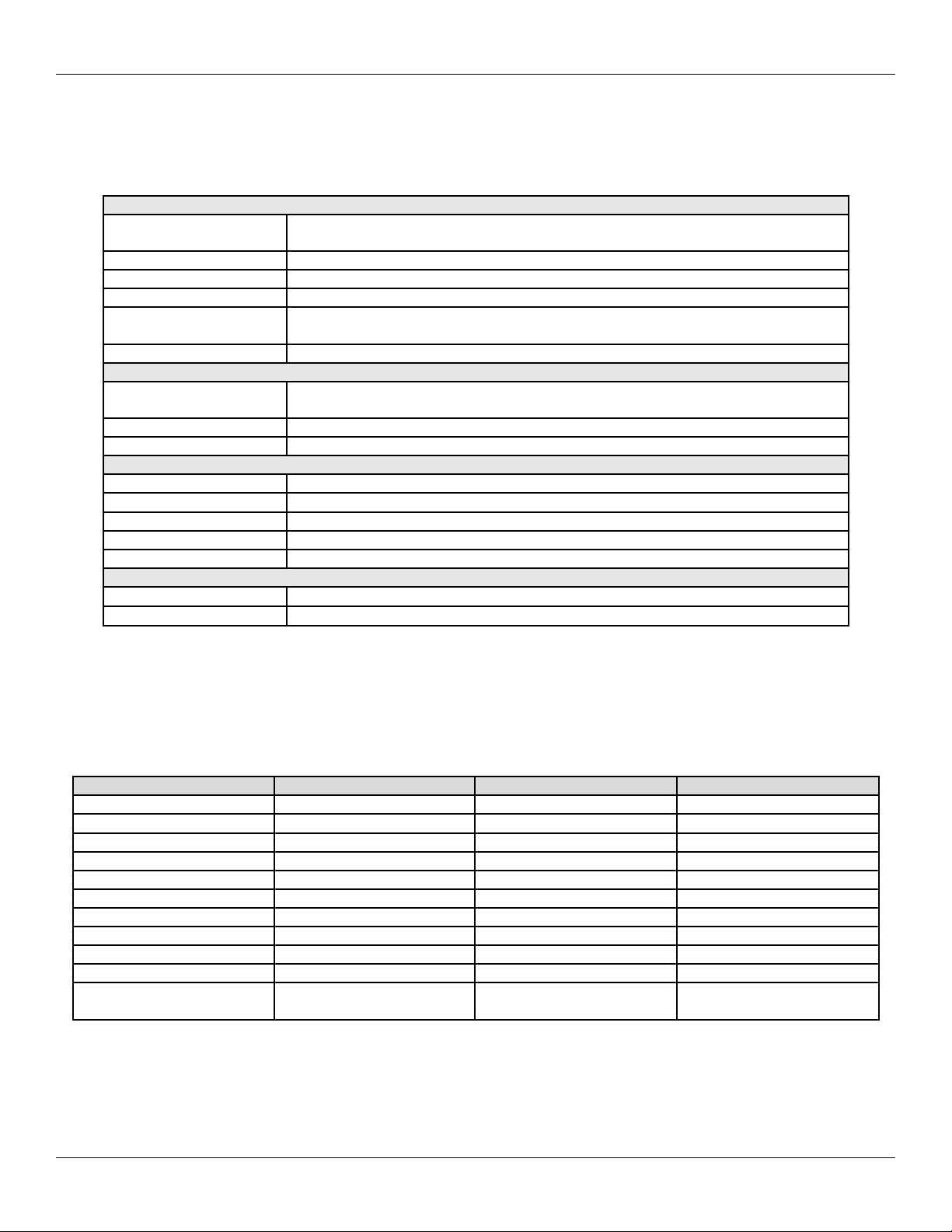
1.1 System Features
Table 1: System Features
Feature Description/Details
Users 2000
Base Capacity Supports 1-4 Max 3 Modules; Controls 1-4 Doors
Additional Capability Network up to 64 doors with additional Max 3 modules
Communication Type
Audit Trail *2000 Event Transaction Log
Front End Support
Programming Max 3 Module supports keypad or PC programming
Auto-Unlock Time Zones
First-In Auto-Unlock Requires valid entry to initiate auto-unlock schedule.
Forced Door Alarm Relay/Timer
Alarm Zone Shunting Relay
Timed Egress Input
Non-Volatile EEPROM Memory
RS-485 Network; Connect via RS-232 to RS-485 Converter, USB to RS485 Converter
or LAN connection using SEG-M or SEG-1.
Each Max 3 Module supports either two Wiegand or Secured Series front End readers
for IN/OUT operation.
9:00 A.M. to 5:00 P.M. Monday-Friday
*Eight user definable time zones for auto-unlock or access control
*32 single day or block holidays
* Indicates feature available with PC software only.
Document #: 6055673, Rev 1.0 D1f Page 5 of 52
Page 6
Section 1: System Features and Specifications IEI Max 3 Installation/Programming Manual
1.2 Specifications
The following table lists the Electrical, mechanical and environmental specifications.
Table 2: Specifications
Electrical
Power Supply
Current Requirements 110mA (backplane with one module); Add 100mA for each Module
Front End 13.8 VDC, 300 mA (max. current draw)
Main Relay 12-24 VAC/DC, 2A (max. contact current)
Alarm Shunt, Door Ajar
and Forced Door Relays
REX/Door Loop Dry contact closure
Wiring Requirements
RS-485 Cable 24AWG, shielded, two twisted-pair telephone cable with a shunt capacitance of 16
Front End Cable Stranded wire with overall foil shield.
REX/Door Loop Cable Stranded wire with overall foil shield.
Mechanical
Enclosure Surface mount
Height 4.25” (10.8cm)
Width 19.5” (49.5 cm)
Length 16.5” (41.9 cm)
Material 19 gauge steel
Environmental
Temperature Tolerance
Recommended Use For indoor use only
16.5VAC 40VA or 50VA Class 2 Transformer (Revere # RT-G1640SL/M, Revere #
RT-G1650SL/M or Globtek, Inc. # DA-40-16.5G)
12-24VAC/DC, 1A (max. contact current)
pF/Ft (required only when using software)
-20°F to 130°F (-28°C to 54°C)
1.3 System Defaults
The following table lists the default settings for the Max 3 Door Control Module.
Table 3: System Defaults
Option Default Setting Option Default Setting
Master Code 1234 Main Relay Time 5 Seconds
Door Ajar Output Time 30 Seconds Forced Door Output Time 10 Seconds
Audio Keypress Feedback Enabled Visual Keypress Feedback Enabled
User Lockout Enabled User Lockout Type By Location
Time Zones Disabled Auto-Unlock Disabled
First-In Auto-Unlock Disabled User Timezone 24 Hours
Daylight Savings Time Enabled DST Format US
Wiegand LED State Active Low Wiegand Sounder State Active Low
Error Lockout Threshold 3 Attempts Error Lockout Duration 10 Seconds
Extended Unlock Time 10 Seconds Facility Code 11
Door Number 1
Auto-Unlock Time Zone
(Without software)
9 A.M to 5 P.M.; Monday
through Friday
Page 6 of 52 Document #: 6055673, Rev 1.0 D1f
Page 7
IEI Max 3 Installation/Programming Manual Section 1: System Features and Specifications
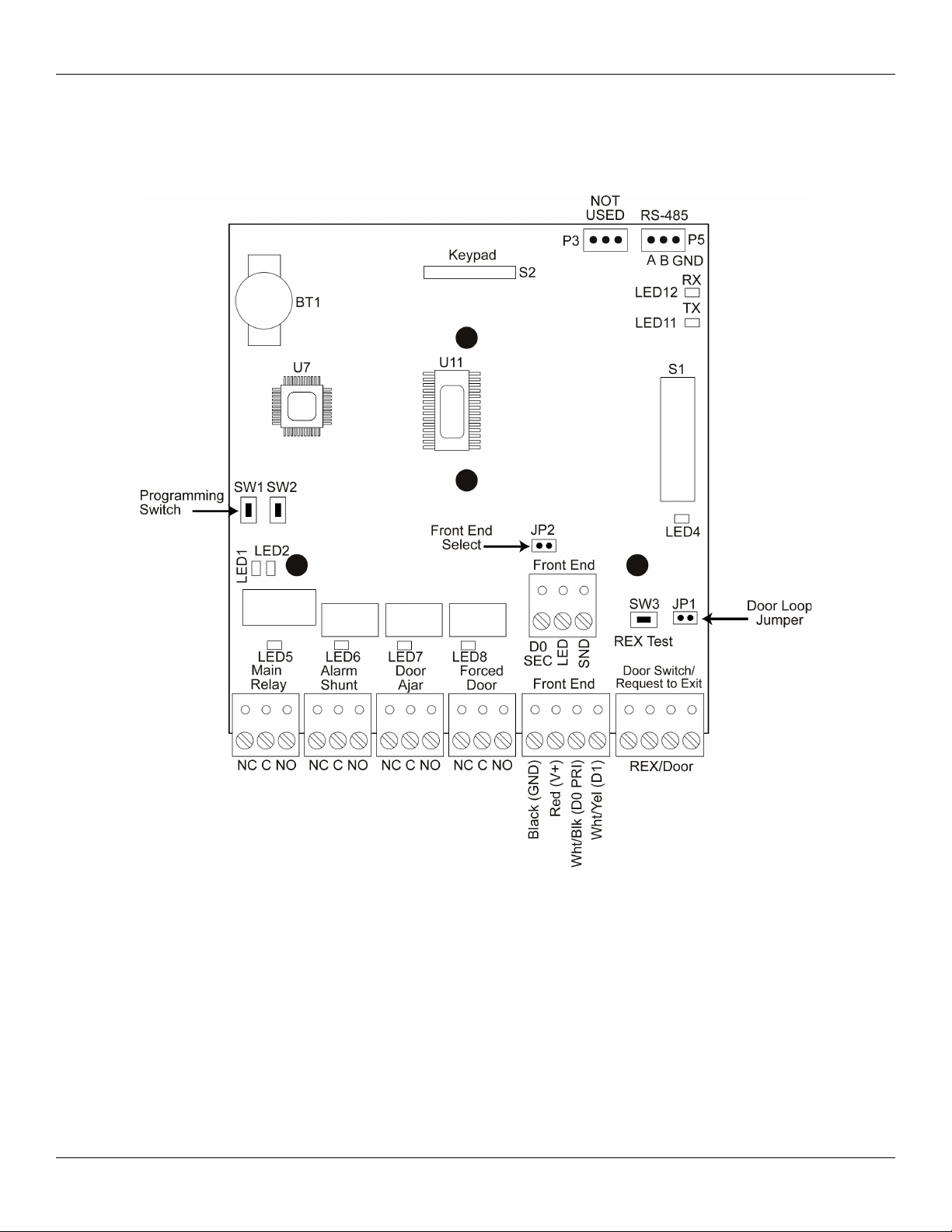
1.4 Max 3 Door Control Module Diagram
The diagram below shows the component locations and terminal connections on the Max 3 Door Control Module.
Communication LEDs
RX = Receive Data
TX = Transmit Data
Figure 1: Max 3 Module Diagram
Document #: 6055673, Rev 1.0 D1f Page 7 of 52
Page 8
Section 1: System Features and Specifications IEI Max 3 Installation/Programming Manual
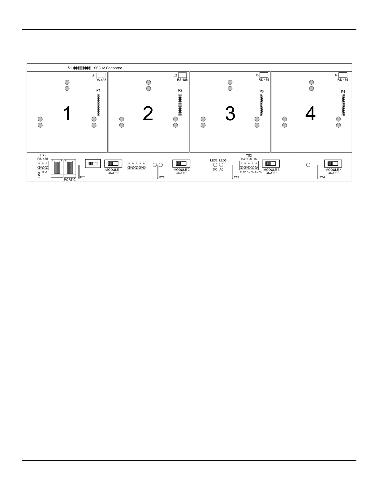
1.5 Backplane Diagram
The diagram below shows the component locations and terminal connections on the Backplane.
Figure 2: Max 3 Backplane Diagram
Notes:
The Max 3 communicates to the PC via an RS-485 connection. For this connection use TS3 on the far left, bottom of the backplane.
The module is then connected to the backplane via connectors J1 through J4 using a wire harness.
Port C is used for configuring the SEG-M, when it's plugged onto S1 on the backplane.
Page 8 of 52 Document #: 6055673, Rev 1.0 D1f
Page 9

IEI Max 3 Installation/Programming Manual Section 2: Installation
Section 2: Installation
This section contains detailed procedures and wiring diagrams for installing the IEI Max 3 Access Control System. This section is
presented in the order you should follow to install the unit. Not every section is necessary for every application.
The system must be installed within the protected area in accordance with the National Electrical Code (NFPA 70), local codes, and
the authority having jurisdiction. It should also be located in an area that is accessible for programming purposes. After the installation
is complete, the cabinet door should remain closed and locked to protect the contents.
Note: Programming commands are inserted into the installation procedures for your convenience. Programming should only be done
after all electrical connections are made and the system is powered up.
2.1 Check the Packing List
Open the box and inside is a metal enclosure. The metal enclosure has a removable lid, to give you easier access when wiring. Inside
the metal enclosure is:
• 1 Backplane mounted on standoffs
• 1 16.5VAC Transformer
• 1 Camlock with key
• 1 Hardware Pack containing:
• 4 Wire nuts (ORANGE
• 4 Wall anchors (BLUE)
• 4 #8 1¼” sheet metal screws
• 4 6-32 x
• 1 Set of battery cables (BLACK AND RED)
• 4 Ground cables (BLACK wire with RED flush tab receptacle) one per Max 3 Module Port
• 1 Max 3 Module
• 1 detachable keypad for programming (Pre-mounted to Max 3 Module)
• 1 Secured Series Software Package
• 1 Max 3 Installation and Programming Manual
3
/8” screws (For Power Supply Mounting)
Note: Max 3 System Kit contains additional components including power supply,
second transformer and proximity reader.
Please check the contents of the enclosure and verify all components on the packing list are present. Taking this inventory will
familiarize you with the components as well as ensure you have a complete kit.
2.2 Mount the Enclosure
The enclosure is designed to be wall mounted (surface mounted) using the supplied hardware. You must mount the enclosure on the
secure side of the door in a secured area such as a locked utility closet. Make sure it is accessible for programming and maintenance
purposes. Do not use the controller as access device to enter or exit through the door.
Mounting Procedure:
Unlock and open the metal enclosure. Notice that the enclosure lid opens from top to bottom so the enclosure lid forms a tabletop for a
convenient workspace.
1. Use the supplied wall anchors and sheet metal screws to secure the enclosure to the wall.
2. Drill 11/64’’ diameter holes for the wall anchors.
3. Tap the wall anchors into the wall until the outer flange is flush to the wall surface.
4. Insert the sheet-metal screws ¾ of the way into the anchors.
5. Hang the enclosure by aligning the slotted holes (cut into the rear of the cabinet) with the sheet-metal screws. Space between
slotted holes; on-center 17” Horizontally and 13” Vertically.
6. The enclosure should now be resting on the sheet-metal screws.
7. Tighten the sheet-metal screws until they are snug.
Document #: 6055673, Rev 1.0 D1f Page 9 of 52
Page 10
Section 2: Installation IEI Max 3 Installation/Programming Manual
2.3 Ground the Unit
Grounding the system before making any electrical connections is imperative!
By grounding the system first you not only increase personal safety during installation, but you also protect the unit from damage due
to static discharge or any other transient voltage effects. We cannot stress enough the importance of completely grounding the unit
before making any connections or even touching the backplane (the large circuit board in the enclosure). Wire as shown and plug the
transformer into a grounded electrical socket.
Do not make any AC
Power connections
until Step 13 of the
installation.
Figure 3: Connecting the GND Terminal from Transformer to the Backplane
TOUCH THE GROUNDED METAL CABINET BEFORE TOUCHING THE BACKPLANE OR
THE MAX 3 DOOR CONTROL MODULE. THIS WILL REMOVE ANY STATIC CHARGE ON
YOUR PERSON. STATIC ELECTRICITY CAN DAMAGE THE ELECTRONIC COMPONENTS
USED ON THE CONTROLLERS.
Page 10 of 52 Document #: 6055673, Rev 1.0 D1f
Page 11
IEI Max 3 Installation/Programming Manual Section 2: Installation
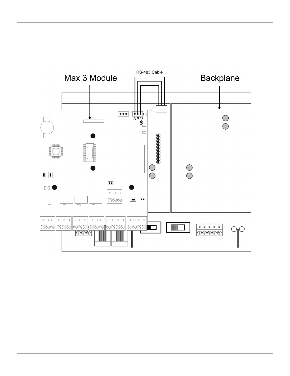
2.4 Connect the RS-485 Cable from the Module to the Backplane
The Max 3 Door Control Module requires an additional three position cable to make the RS-485 connection to the backplane. This
cable is connected from P5 on the upper right corner of the module to the corresponding three position connector underneath each
module on the top edge of the backplane. The connectors from left to right are labeled J1 (for module 1) to J4 (module 4). Simply plug
one end of the cable into P5 and the other end into the connector on the backplane. The diagram below illustrates how to connect
module 1 to the backplane.
Figure 4: RS-485 Connection from Max 3 Module to Backplane
Document #: 6055673, Rev 1.0 D1f Page 11 of 52
Page 12

Section 2: Installation IEI Max 3 Installation/Programming Manual
2.5 Connect Additional Modules to the Backplane
The backplane has 4 expansion ports for Max 3 Modules. Provided with the unit is one Max 3 Module which is installed into port 1 of
the Backplane. If additional Max 3 Modules are purchased for this system, insert them into the remaining ports. You must connect
each module to the RS-485 connector on the backplane as shown in the previous section.
Figure 5: Connecting Additional Modules to the Backplane
To install additional Max 3 Modules:
1. Slide the Door Control Module onto the pin-rail marked Px (x = Expansion Port #; Example: P2) located on the backplane.
2. Align the 3 holes in the Door Control Module with the standoffs mounted on the backplane. Gently press down on the
Module to snap it on onto the standoffs.
3. Using the supplied 3-position wire harness, connect P5 on the module to the RS-485 connector on the backplane.
4. Turn the Module Power Switch (located on the backplane) to “ON”.
Page 12 of 52 Document #: 6055673, Rev 1.0 D1f
Page 13

IEI Max 3 Installation/Programming Manual Section 2: Installation
2.6 Wire an Electric Door Lock to the Main Relay of the Max 3 Module
The locking device is connected to terminal strip TS1 as shown in
the diagram on the right. The two diagrams below show how to
connect both a Maglock and an Electric Strike using an external
power supply.
For either locking device, positive voltage (V+) from an external
power source is connected to the relay common terminal (C).
When using a Maglock, connect the lock's positive side to the
normally closed (NC) terminal and the negative side to negative on
your power supply. When using an Electric Strike, connect the
lock's positive side to the normally open (NO) terminal and the
negative side to negative on your power supply.
NOTES:
You must use an external power supply to power your
lock.
The relay is a FORM C DRY CONTACT, which
means there is no output voltage on the relay contacts.
When using AC voltage, polarity does not matter.
Connecting a Maglock (Fail-Safe) Connecting an Electric Strike (Fail-Secure)
Programming the Main Relay Time:
The command sequence below is used to change the Main Relay Time. The default value is 5 seconds.
Action Press
Enter Program Mode 99 # Master Code *
Program Main Relay Time
Exit Program Mode *
Document #: 6055673, Rev 1.0 D1f Page 13 of 52
11 # time # 0 # **
(time = 1 to 99 seconds)
Page 14
Section 2: Installation IEI Max 3 Installation/Programming Manual
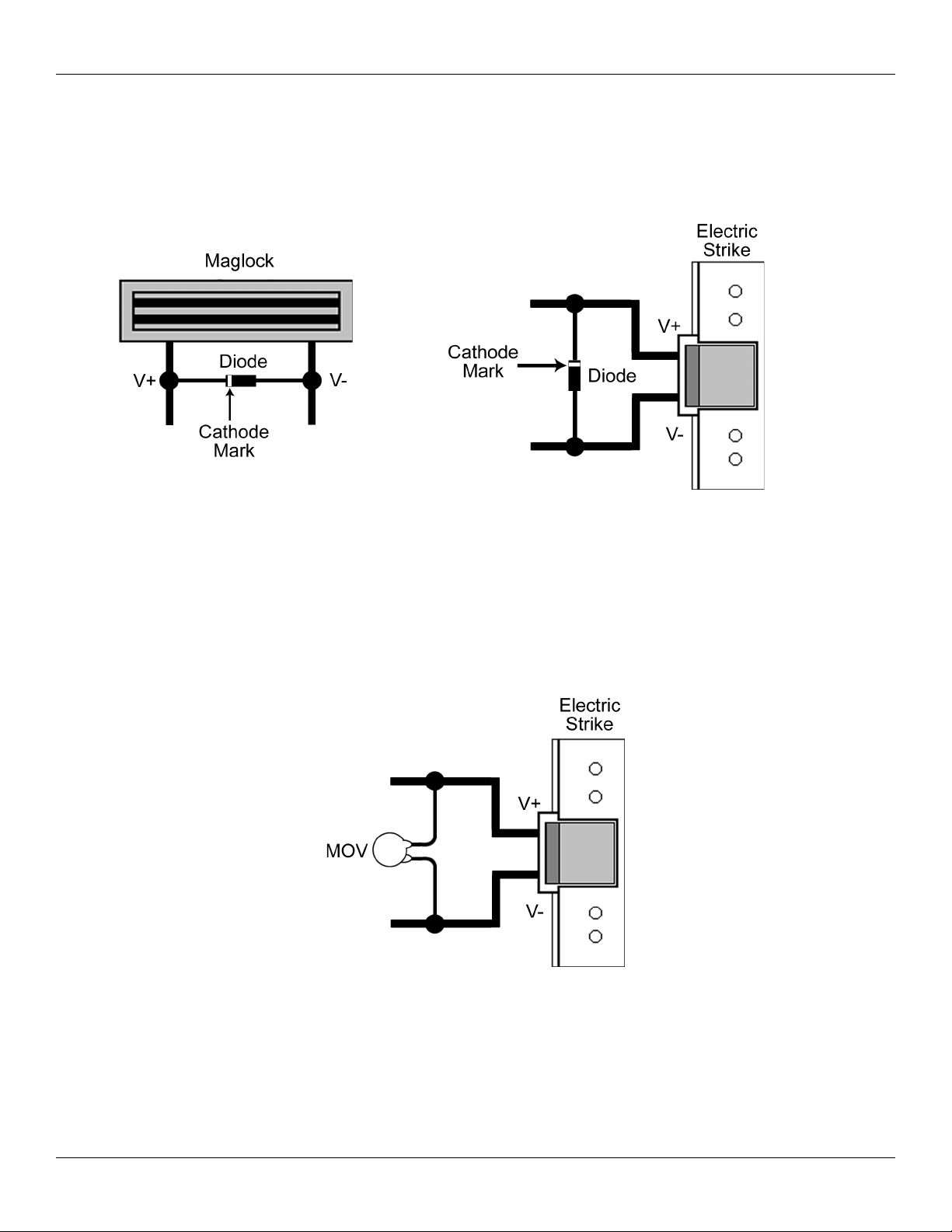
2.6.1 Installing a Diode to Prevent Electrical Kickback from Lock – DC Locks Only
If your electric locking device does not come pre-installed with internal protection for electrical “kickback voltage” use the supplied
1N4004 diode for DC locks only. This “kickback voltage” could possibly damage the Max 3 control module and installing the diode
could help prevent this from happening. When installing the diode, connect it across the positive (V+) and negative (V-) of your
locking device. The diode is polarized, which means the cathode mark (silver band at one end) must be connected to the positive
connection as shown below. You must connect the diode as close as possible to the locking device for it to work properly.
Figure 7: Connecting Diode
Across Maglock
Figure 6: Connecting Diode Across Strike
2.6.2 Installing an MOV to Prevent Electrical Kickback from Lock – AC Locks Only
If your electric locking device does not come pre-installed with internal protection for electrical “kickback voltage” use the supplied
MOV for AC locks only. This “kickback voltage” could possibly damage the Max 3 control module and installing the MOV could
help prevent this from happening. When installing the MOV, connect it across the AC connections to your locking device. The MOV
is not polarized so it does not matter which direction you install it. You must connect the MOV as close as possible to the locking
device for it to work properly.
Figure 8: Connecting MOV Across
Strike
Page 14 of 52 Document #: 6055673, Rev 1.0 D1f
Page 15
IEI Max 3 Installation/Programming Manual Section 2: Installation
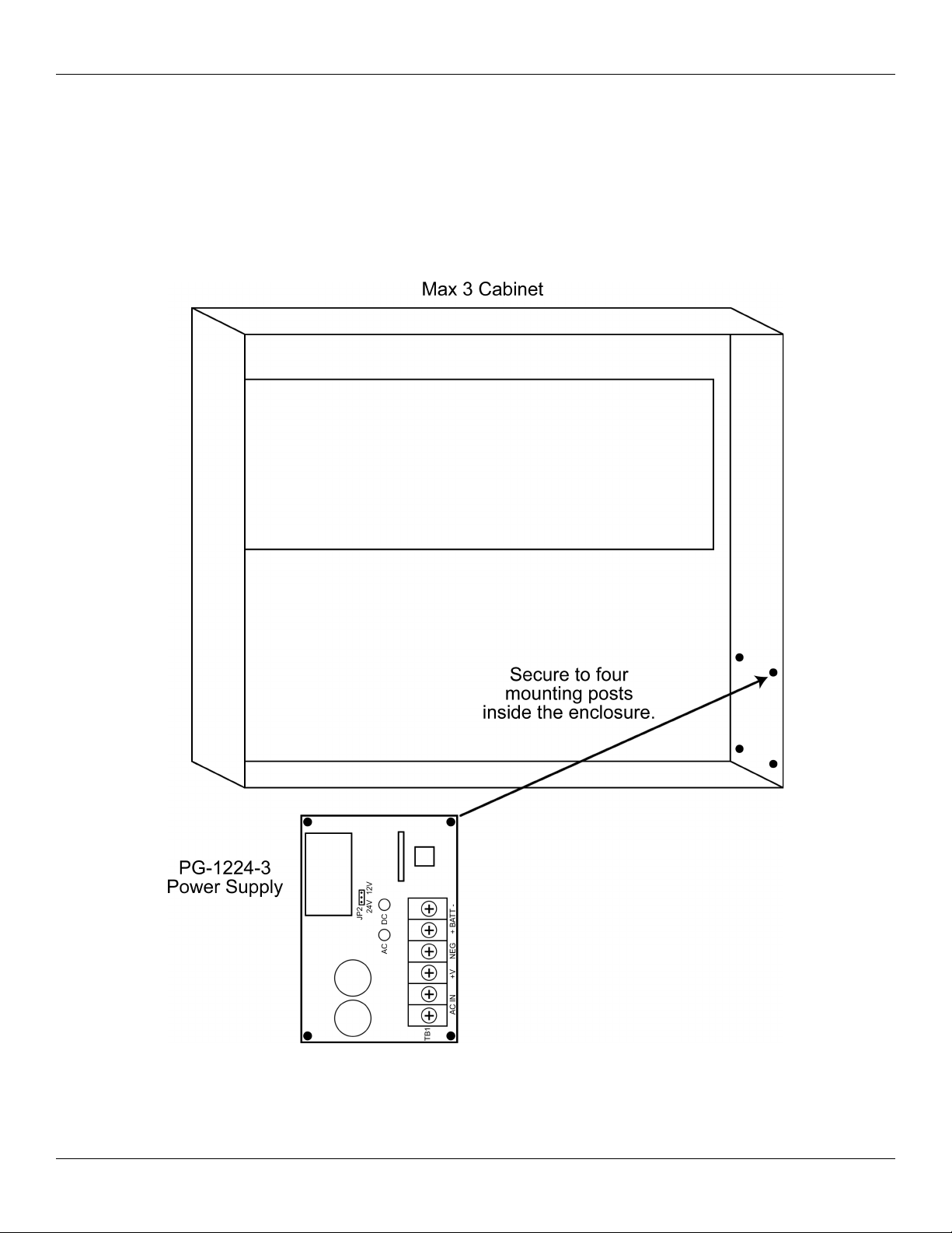
2.6.3 Mounting the PowerGard PG-1224-3 Power Supply for Lock Power
The Max 3 System Kit includes the PowerGard PG-1224-3 Power Supply, which is used to power your locking device. This power
supply is not included when you purchase the panel only, but you can purchase it separately. The Max 3 enclosure has four mounting
posts used to mount the IEI PowerGard PG-1224-3 Power Supply. To mount the power supply use the four supplied 6-32 x 3/8” screws
to secure it to the four posts in the bottom right corner of the enclosure as shown in the diagram below. Refer to section 2.6.4 for
wiring information.
Figure 9: Mounting the PG-1224-3 Power Supply
Document #: 6055673, Rev 1.0 D1f Page 15 of 52
Page 16
Section 2: Installation IEI Max 3 Installation/Programming Manual
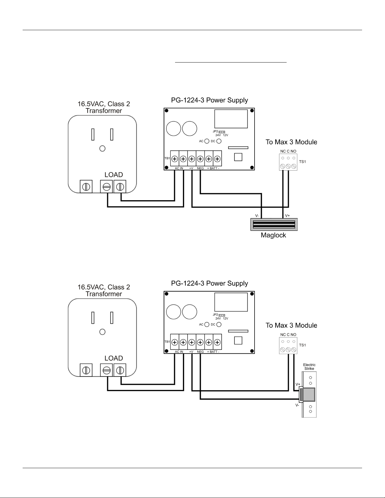
2.6.4 Wiring the PowerGard PG-1224-3 Power Supply for Lock Power
The Max 3 System Kit includes a second transformer for use with the power supply. The second transformer is not included when you
purchase just the panel. Using the 16.5VAC transformer the power supply output must be set for 12VDC. The power supply is capable
of supplying 2.5 Amps of current for your lock. To power your lock using the PG-1224-3 Power Supply follow the diagrams below.
Figure 10: Wiring a Maglock to the PG-1224-3 Power Supply
Figure 11: Wiring an Electric Strike to the PG-1224-3 Power Supply
Page 16 of 52 Document #: 6055673, Rev 1.0 D1f
Page 17

IEI Max 3 Installation/Programming Manual Section 2: Installation
2.7 Connect a Secured Series Front End (SSFE) Reader to the Door Control Module
The Max 3 supports IEI Secured Series Front Ends, which include keypads, card readers and touch chip readers. These are connected
to to the Front End terminal strip TS5. You can connect up to two readers to each Door Control Module, for In/Out operation by
simply wiring them in parallel (both readers to the same four screw terminals). Each screw terminal is labeled with a wire color (black,
red, white/black and white yellow). These correspond to the color wire on the wire harness supplied with the front end reader.
You must use a four-conductor stranded cable with overall foil shield to connect the Front End to the Door Control Module. You also
must terminate the drain wire (the bare wire inside the foil shield), from the front end cable, to the fast-tab located on the Max 3
Backplane. There is a fast-tab located under each module on the lower edge of the backplane. They are labeled FT1, FT2, FT3 and
FT4. Connect the drain wire from the front ends connected to module one to FT1 and so on. IEI has included four ground cables and
wire-nuts to make this connection. Do not terminate the drain wire at the Front End Reader. Cut off the exposed drain wire and
wrap the insulation and the foil shield in electrical tape.
Note: The Max 3 Door Control Module must be configured to operate in Secured
Series Front End Mode. To do this, locate jumper JP2 above terminal strip TS7 and
place the jumper on both pins.
Wire Size vs. Cable Length Chart
Distance Wire Size
250 Feet 22 AWG
500 Feet 20 AWG
1000 Feet 18 AWG
Note: If you experience problems with
front end communications after connecting
a second keypad or reader, wiring a
separate ground wire from each keypad to
the black terminal on the Max 3 DCM may
solve the issue. If this does not fix the
problem contact IEI Technical Support.
Figure 12: Connect Secured Series Front End to DCM
Document #: 6055673, Rev 1.0 D1f Page 17 of 52
Page 18

Section 2: Installation IEI Max 3 Installation/Programming Manual
2.8 Connect the Primary Wiegand Front End Reader (IN Reader)
Wiegand readers are connected directly to the Front End Terminals on the Door Control Module. The primary reader (IN) should be
mounted on the exterior of the door and used to gain access into the secured area. The diagram and table below describe the
connections in detail. Please note that the Primary Wiegand Reader Data 0 wire is connected to DO PRI (Data 0 Primary) on terminal
strip TS5.
The LED connection is used to indicate status of the Main Relay and the Sounder connection is used to indicate various error
conditions. These are explained in more details in later sections.
You must use a four to six conductor stranded cable with overall foil shield to connect the Front End to the Door Control Module. You
also must terminate the drain wire (the bare wire inside the foil shield), from the front end cable, to the fast-tab located on the Max 3
Backplane. There is a fast-tab located under each module on the lower edge of the backplane. They are labeled FT1, FT2, FT3 and
FT4. Connect the drain wire from the front ends connected to module one to FT1 and so on. IEI has included four ground cables and
wire-nuts to make this connection. Do not terminate the drain wire at the Front End Reader. Cut off the exposed drain wire and
wrap the insulation and the foil shield in electrical tape.
IMPORTANT: The Max 3 Door Control Module must be configured to
operate in Wiegand Front End Mode. To do this, locate jumper JP2 above
terminal strip TS7 and place the jumper on one pin. This is the default
condition.
Primary Wiegand Reader Connections
Wiegand Reader DCM Terminal Strip
V- (Power) Black TS5
V+ (Power) RED TS5
Data 0 D0 PRI TS5
Data 1 D1 TS5
LED Control LED TS7
Sounder Control SND TS7
Note: The primary reader
records an IN event in the
transaction log.
Figure 13: Connect Primary Wiegand Front End
Reader to DCM
Page 18 of 52 Document #: 6055673, Rev 1.0 D1f
Page 19

IEI Max 3 Installation/Programming Manual Section 2: Installation
2.9 Connecting a Secondary Wiegand Front End Reader (OUT Reader)
The diagram below shows how to connect a secondary (out) reader to the Door Control Module. The secondary reader (OUT) should
be mounted on the interior side of the door and used to exit the secured area. Please note that the Secondary Wiegand Reader Data 0
wire is connected to DO SEC (Data 0 Secondary) on terminal strip TS7.
The LED connection is used to indicate status of the Main Relay and the Sounder connection is used to indicate various error
conditions. These are explained in more details in later sections.
You must use a four to six conductor stranded cable with overall foil shield to connect the Front End to the Door Control Module. You
also must terminate the drain wire (the bare wire inside the foil shield), from the front end cable, to the fast-tab located on the Max 3
Backplane. There is a fast-tab located under each module on the lower edge of the backplane. They are labeled FT1, FT2, FT3 and
FT4. Connect the drain wire from the front ends connected to module one to FT1 and so on. IEI has included four ground cables and
wire-nuts to make this connection. Do not terminate the drain wire at the Front End Reader. Cut off the exposed drain wire and
wrap the insulation and the foil shield in electrical tape.
IMPORTANT: The Max 3 Door Control Module must be configured to
operate in Wiegand Front End Mode. To do this, locate jumper JP2 above
terminal strip TS7 and place the jumper on one pin. This is the default
condition.
Secondary Wiegand Reader Connections
Wiegand Reader DCM Terminal Strip
V- (Power) Black TS5
V+ (Power) RED TS5
Data 0 D0 SEC TS7
Data 1 D1 TS5
LED Control LED TS7
Sounder Control SND TS7
Note: The secondary reader
records an OUT event in the
transaction log.
Figure 14: Connect Secondary Wiegand Front End
Reader to DCM
Document #: 6055673, Rev 1.0 D1f Page 19 of 52
Page 20

Section 2: Installation IEI Max 3 Installation/Programming Manual
2.10 Wire a Request to Exit (REX) device and Door Contact
Note: Use stranded wire with
overall foil shield for the
REX and Door Contact
cables. Connect the drain
with to the fast-tab on the
backplane.
Figure 15: Wiring a REX Switch and Door Contacts
Request to Exit (REX)
Door Switch Input
This is a normally open loop, when momentarily closed activates the Main Relay for the
length of time programmed in the Main Relay Time (command 11).
This is a normally closed loop that tells the Max 3 the door status. This is used for the Door
Ajar, Forced Door and Auto-Relock features.
Auto-Relock
Auto Re-lock refers to the feature that automatically locks the door one second after the door contact switch is opened. This allows
you to program a long unlock time, when required, without worrying about the door remaining open after the person has entered. No
programming is necessary for this feature, but it does require you connect a door contact switch as shown in the diagram above.
Remember you must remove jumper JP1 for the door contact input to operate.
Page 20 of 52 Document #: 6055673, Rev 1.0 D1f
Page 21

IEI Max 3 Installation/Programming Manual Section 2: Installation
2.11 Wire the Alarm Shunt Relay
The Alarm Shunt Relay is used when you are controlling access to a door that is monitored by an external alarm system. This relay
activates at the same time as the Main Relay (by either a valid code/card or REX) so you can bypass the existing alarm panel, as
shown in the diagram below. For this feature you must wire dedicated door contact to terminals TS6 (door contact switch input) as
shown below. The Alarm Shunt Relay remains energized until one second after the door contact switch input is closed. Remember you
must remove jumper JP1 for the door contact input to operate.
Figure 16: Wiring the Alarm Shunt Relay
Document #: 6055673, Rev 1.0 D1f Page 21 of 52
Page 22

Section 2: Installation IEI Max 3 Installation/Programming Manual
2.12 Wire the Door Ajar Relay
The Door Ajar Relay output alerts personnel that the door is being held, or propped open, after a valid access or REX. For this feature
to operate you must wire a dedicated door contact switch to the door terminals on TS6 (door contact switch input) as shown below.
Once the door contact switch input is opened, the Door Ajar timer begins. When the time reaches the time programmed in the Door
Ajar Time (command 44), the relay energizes and remains energized until the door contacts are closed. Remember you must remove
jumper JP1 for the door contact input to operate.
The diagram below shows how switch positive power (V+) to an alarm device. The Relay is rated to handle 1 Amp of current at either
12 or 24 Volts AC/DC. Alarm device(s) are not included with IEI equipment.
Figure 17: Wiring the Door Ajar Relay
Programming the Door Ajar Time:
The command sequence belows shows how to program the Door Ajar Time. The default value is 30 seconds.
Action Press
Enter Program Mode 99 # Master Code *
Program Door Ajar Time
Exit Program Mode *
Page 22 of 52 Document #: 6055673, Rev 1.0 D1f
44 # time # 0 # **
(time = 10 to 990 seconds)
Page 23

IEI Max 3 Installation/Programming Manual Section 2: Installation
2.13 Wire the Forced Door Relay
The Forced Door Relay Output alerts personnel that the door was opened without authorization. For this feature to operate you must
wire a dedicated door contact switch to the door terminals on TS6 (door contact switch input) as shown below. Remember you must
remove jumper JP1 for the door contact input to operate. If these door contacts are opened without a valid access or REX, the Forced
Door Relay energizes immediately. It remains energized until either a valid code is entered or card presented to the Front End Reader,
a valid code is entered on the Max 3 Module or the Forced Time (command 45) expires.
The diagram below shows how to switch positive power (V+) to an alarm device. The Relay is rated to handle 1 Amp of current at
either 12 or 24 Volts AC/DC. Alarm device(s) are not included with IEI equipment.
Figure 18: Wiring the Forced Door Relay
Programming the Forced Door Time:
The command sequence belows shows how to program the Forced Door Time. The default value is 10 seconds.
Action Press
Enter Program Mode 99 # Master Code *
Program Forced Door Time
45 # time # 0 # **
(time = 10 to 990 seconds)
Exit Program Mode *
Document #: 6055673, Rev 1.0 D1f Page 23 of 52
Page 24

Section 2: Installation IEI Max 3 Installation/Programming Manual
2.14 Network the Max 3
The following section describes the various ways to connect the Max 3 to a personal computer (PC), as well as connecting more than
one Max 3 together. You can connect up to 64 Max 3 doors together on a single network.
IMPORTANT: When using the PC software to manage multiple doors you must
program a unique door number into each Door Control Module using the
following command: 43 # 0 # Door Number # ** (Door Number = 1 to 64). Refer
to section 3.3.
2.14.1 Connect the Max 3 Backplane Directly to a PC
The Max 3 connects to a PC using RS-485 communications. However, a PC has either an RS-232 serial COM port or a USB port.
This means that in order to connect to a PC you must use either an RS-232 to RS-485 converter OR a USB to RS-485 converter. RS485 communications does have some significant advantages over other connection types, such as increased distance of up to 4000 feet
using the appropriate cable, the devices are wired in parallel which means if one unit goes off-line the rest are unaffected and
increased data transfer speed.
To make this connection, connect the Data A, Data B and GND terminals on TS3 (See below) to the same corresponding connections
on your converter. Then make the connection from the converter to your PC. Please refer to the instructions with your specific
converter for complete details on that device.
Note: The Max 3 Module must be connected to the backplane
using the wire harness described in section 2.4.
Note: The maximum
distance between the
backplane and the converter
is 4000 feet using 24AWG,
shielded, two twisted-pair
telephone cable with a shunt
capacitance of 16 pF/Ft.
Figure 19: Wiring Max 3 Backplane to a PC
Page 24 of 52 Document #: 6055673, Rev 1.0 D1f
Page 25

IEI Max 3 Installation/Programming Manual Section 2: Installation
2.14.2 Connect Multiple Backplanes Together
The diagram below shows how to connect multiple backplanes together and then back to a PC. The units are wired in parallel, which
means you connect TS3 on both backplanes back to the RS-485 converter. You can either daisy-chain them or wire them all directly
back to the converter, depending what your installation requires. When connecting multiple backplanes, remember that each
backplane can be up to 4000 feet away from the converter. For example if your PC was centrally located with two units in either
direction at 4000 feet, the two backplanes would be 8000 feet apart. However, if you daisy-chain them, the last backplane in line, can't
be more than 4000 feet away. Below is an example of daisy-chaining backplanes together.
Note: The maximum
distance between any
backplane and the converter
is 4000 feet using 24AWG,
shielded, two twisted-pair
telephone cable with a shunt
capacitance of 16 pF/Ft.
Figure 20: Connecting Multiple Backplanes Together
Document #: 6055673, Rev 1.0 D1f Page 25 of 52
Page 26

Section 2: Installation IEI Max 3 Installation/Programming Manual
2.14.3 Connect the SEG-M to the Max 3 (LAN/WAN Connection)
You can connect your Max 3 to your LAN/WAN by using the SEG-M, Secured Ethernet Gateway. Follow the instructions below and
refer to the diagram.
The connection from the SEG-M to the Max 3 requires you to plug the module onto the backplane connector S1 to power the unit.
You must also use the six-conductor wire harness from J1 on the SEG-M to P5 on the module and J1 on the backplane. If you have
more than one module on the backplane, you must connect each module to the corresponding RS-485 connector (J2, J3 or J4)
underneath the module as described in section 2.4.
To connect additional backplanes to the system, simply connect TS3 on the first backplane to TS3 on the next backplane as shown
below. The SEG-M is only required on the first backplane of the system (up to 64 doors Max; if you require more doors an additional
SEG-M is required).
Note: The maximum
distance between the first
backplane with the SEG-M
and the next backplane is
4000 feet using 24AWG,
shielded, two twisted-pair
telephone cable with a shunt
capacitance of 16 pF/Ft.
Figure 21: Connecting the SEG-M to the Max 3
Page 26 of 52 Document #: 6055673, Rev 1.0 D1f
Page 27

IEI Max 3 Installation/Programming Manual Section 2: Installation
2.14.4 Connecting the SEG-1 to the Max 3 (LAN/WAN Connection)
You can also use the SEG-1 to connect your Max 3 system to your LAN/WAN. Follow the instructions below and refer to the
diagram.
Run your RS-485 cable between terminal strip TS1 on the SEG-1 to TS3 on the backplane as shown in the diagram. You must also
connect each module to the backplane by connecting the supplied 3-conductor wire harness from P5 to the RS-485 connector
underneath each module on the backplane (J1 through J4).
To connect additional backplanes to the system, simply connect TS3 on the first backplane to TS3 on the next backplane as shown
below. The SEG-1 is only required on the first backplane of the system (up to 64 doors Max; if you require more doors an additional
SEG-1 is required).
Note: The maximum
distance between any
backplane and the SEG-1 is
4000 feet using 24AWG,
shielded, two twisted-pair
telephone cable with a shunt
capacitance of 16 pF/Ft.
Figure 22: Connecting the SEG-1 to the Max 3
Document #: 6055673, Rev 1.0 D1f Page 27 of 52
Page 28

Section 2: Installation IEI Max 3 Installation/Programming Manual
2.15 Installing a Tamper Switch
IEI recommends you install a tamper switch. The tamper switch must be mounted inside the locked cabinet and must activate if the
cabinet door is opened. The tamper switch must be wired to an alarm panel or other device that sounds an alarm and/or prevents
anyone from gaining access through the protected door.
IEI recommends using a Sentrol 3012 tamper switch (not provided).
To use this tamper switch, simply clip the switch on the side of the cabinet on the interior, then wire the leads to your alarm device
using the appropriate cable. See diagram below.
Figure 23: Installing a Tamper Switch
Page 28 of 52 Document #: 6055673, Rev 1.0 D1f
Page 29

IEI Max 3 Installation/Programming Manual Section 2: Installation
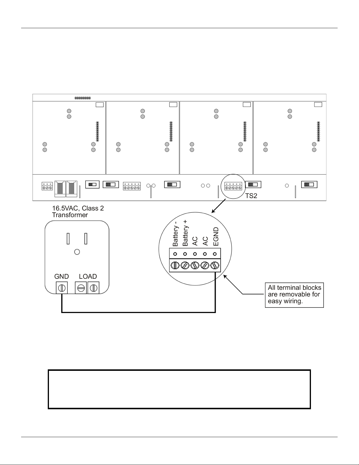
2.16 Complete Connections Between the 16.5 VAC Transformer and Backplane
Connect the 16.5 VAC Transformer (included with the Max 3) to the Backplane at the terminals marked AC and EGND.
Provided with the Max 3 are Backup Battery Connection Cables. Connect these cables from your 12V battery (7AH Recommended)
to the Backplane at the terminals marked B+ and B-. Polarity is an issue! Be sure you know which battery terminals are positive and
negative BEFORE you connect your battery to the Backplane.
Figure 24: Completing the Transformer Connections
Document #: 6055673, Rev 1.0 D1f Page 29 of 52
Page 30

Section 2: Installation IEI Max 3 Installation/Programming Manual
2.17 Power up the System
Plug the transformer into a grounded 110 VAC electrical outlet. You should now have power to your system. Check the power status
by checking the following:
On the Backplane:
• LED 5 should be lit - This indicates that AC Power is present
• LED 2 should be lit - This indicates that DC Power is available on the Backplane
On the Max 3 Module:
• LED 1 should be lit - This indicates that the Max 3 Module is receiving power and functioning
• LED 4 should be lit - This indicates that the Front End Reader is receiving power
If the above requirements are met the system is now powered up and ready for programming and operation.
If the above requirements are not met see the Troubleshooting Section.
Page 30 of 52 Document #: 6055673, Rev 1.0 D1f
Page 31

IEI Max 3 Installation/Programming Manual Section 3: Programming
Section 3: Programming
This section contains the details of programming the Max 3 Door Control Module using the detachable keypad. If you are using the
PC software, this section may not apply, but you may find it useful to familiarize yourself with the various features available in the
Max 3. To see a complete list of programming commands refer to the programming options chart at the end of this section.
3.1 Programming Methods
There are two ways you can program the Max 3 Door Control Module. You can either program it using the detachable keypad or you
can program it using the PC software. Using the PC software gives you access to many more features than you would have
programming through the keypad only. This manual covers only programming through the keypad, although it does refer to features
that require the PC software to use to it's fullest extent.
The diagram below shows how to connect the detachable keypad to the Door Control Module. The keypad comes pre-installed on the
first module, but to program additional modules you must remove it and connect to the module you are programming.
Figure 25: Plug on Detachable Keypad
Document #: 6055673, Rev 1.0 D1f Page 31 of 52
Page 32

Section 3: Programming IEI Max 3 Installation/Programming Manual
3.2 Entering Program Mode and Changing the Master Code
The following sections explains how to enter program mode and change the master code. You also have the option to program a
supervisor user, which allows an additional person to add and delete users.
3.2.1 Entering Program Mode
The first step in programming the Max 3 Door Control Module is to place it into program mode by using the master code, which is
defaulted to 1234.
To place the unit in program mode, press: 99 # Master Code *
When the unit is in program mode the yellow LED flashes slowly.
When you are done programming, to exit program mode press the * key and the yellow LED stops flashing.
If at any point you make a programming error (either press a wrong key or perform a command the unit does not recognize), the unit
produces a program error by turning on the yellow LED solid. To clear a program error, simply press the * key.
Note: If you don't know the master code press the program button (SW1) on the main circuit board. Momentarily pushing this button
forces the unit into program mode. You then should change the master code immediately.
3.2.2 Changing the Master Code
The master code is stored in user memory location 1 and used to enter program mode. To change the master code use the following
programming sequence:
Action Command
Enter Program Mode 99 # master code *
Change Master Code 1 # new master code * new master code *
Exit Program Mode *
Note: Throughout the programming section the last step is to exit program mode. If you are going to program multiple users or
keypad options, you are not required to exit program mode after each command sequence. You may continue to the next programming
command without exiting program mode. When all your programming is complete, you can then exit program mode by pressing the *
key.
3.2.3 Programming a Supervisor Code
The following table shows how to program a supervisor code. User location 2 is reserved for the supervisor code. This user has access
to only user programming commands and can't change other system related options and parameters.
Action Command
Enter Program Mode 99 # master code *
Program a Supervisor Code Code 2 # new code * new code *
Exit Program Mode *
Page 32 of 52 Document #: 6055673, Rev 1.0 D1f
Page 33

IEI Max 3 Installation/Programming Manual Section 3: Programming
3.3 Changing the Door Number
Each Max 3 Door Control Module is assigned a door address or door number. The door number is used to identify each unit when
they are networked together. You can network up to 64 Max 3 Door Control Modules together. You must change the door number
when you are using the PC software. The default door number is 1. To change it, follow the instructions below.
Action Command
Enter Program Mode 99 # master code *
Change the Door Number 43 # 0 # Door Number # * *
Exit Program Mode *
3.4 Changing the Main Relay Time
The Main Relay Time is defaulted to operate for 5 seconds. Command 11 is used to reprogram this time. This time affects standard
unlock users (type 1). If you need to program the Main Relay to toggle, you must program a toggle user. See the user section for
details on user types.
Action Command
Enter Program Mode 99 # master code *
Change Main Relay Time 11 # unlock time * 0 * (1 to 255 seconds)
Exit Program Mode *
3.5 Setting the Time and Date
You must program the time and date into each Door Control Module in order for the timezone and transaction event log features to
work. Follow the instructions below to reprogram the time and date.
Action Command
Enter Program Mode 99 # master code *
Set the Time 41 # HHMM # 0 # **
(HH = Hours; MM = Minutes)
Time is in 24 hour format.
Set the Date 42 # MMDDYY # DOW # **
(MM = Month; DD = Day; YY = Year; DOW =
Day of Week: 1 = Sunday, 2 = Monday, 3 =
Tuesday, 4 = Wednesday, 5 = Thursday, 6 = Friday,
7 = Saturday)
Exit Program Mode *
Document #: 6055673, Rev 1.0 D1f Page 33 of 52
Page 34

Section 3: Programming IEI Max 3 Installation/Programming Manual
3.6 Programming Users
The following section describes in detail how to program users. Each Max 3 Door Control Module can store up to 2000 users. Each
user is stored in a unique position in the units memory. This is referred to as the user location. Codes can be from 1 to 6 digit in length
in any combination. If at any point while programming a code or a card you get a programming error (solid yellow LED), and you
know you are entering the command correctly, make sure that the code or card is not already programmed. If you are unsure try
entering that code or presenting that card outside of program mode and see if you are granted access. If so, you must use a different
code or card for that user.
Note: IEI recommends that, if you are not using software, you keep a list of all the
users you have programmed in the device, in case you need to modify or delete a
particular user later on.
3.6.1 User Types
The table below identifies and describes the four user types supported by the Max 3. The user type number is used in programming
commands in the subsequent sections where it indicates “user type.”
Table 4: User Types
User Type Name User Type Number Description
Toggle User 0 Toggle users are used to latch the Main Relay in the unlocked
position for an indefinite period of time. Entering the same (or
another) toggle code, re-locks the unit.
Standard Access 1 Normal access users are the default user type. This user type unlocks
the door for the duration of the Main Relay Time set in command 11.
See section 3.4 for details.
Lockout User 3 A Lockout user is used to lock out other users from gaining access
through the door. Refer to section 3.10 for details on user lockout.
Extended Unlock User 4 Extended Unlock users operate like standard access users, except
they use a different unlock time programmed using command 32,
parameter 3. It is defaulted to 10 seconds. See section 3.8 for details.
Singe Use User 5 Single use users are allowed to gain access only once. After you enter
this code/card the user is deleted from memory.
Relock User 6 A Relock user is used to relock the door if it was toggled open or is in
auto-unlock. Once entered, the door relocks immediately.
Emergency User 7 An Emergency user is a special user that can't be locked out by a user
lockout code. This user also uses the extended unlock time. It is
defaulted to 10 seconds. See section 3.8 for details.
Page 34 of 52 Document #: 6055673, Rev 1.0 D1f
Page 35

IEI Max 3 Installation/Programming Manual Section 3: Programming
3.6.2 Programming a “Code Only” User
To program a “Code Only” use command 50. This user gains access by entering their code on the keypad. Refer to table 4 for details
on user types. Codes can be from 1 to 6 digit in length in any combination. The programming sequence is as follows:
Note: This programming command applies to Secured Series Front End Keypads only.
Action Command
Enter Program Mode 99 # master code *
Program User 50 # user type # user location # code * repeat code *
Exit Program Mode *
3.6.3 Programming “Card Only” Users by Presentation
To program a “Card Only” user by presentation (by presenting the card to the reader) use command 50. This user type gains access by
presenting their card to the front end reader. Refer to table 4 for details on user types. The programming sequence is as follows:
Action Command
Enter Program Mode 99 # master code *
Program User 50 # user type # user location # * * <present card>
Exit Program Mode *
3.6.4 Programming 26-Bit “Card Only” Users without Presentation
To program a 26-Bit “Card Only” user without presentation (without presenting the card to the front end reader) use command 51.
Refer to table 4 for details on user types. This command is useful, if you want to program a card, but you don't have the physical card
with you. When programming cards with this command, you must program the facility code, using command 32, parameter 2,
prior to programming users. The programming sequence to program cards is as follows:
Note: This programming command applies to Wiegand Front Ends only.
Action Command
Enter Program Mode 99 # master code *
Program User 51 # user type # user location # card number * card
number *
Exit Program Mode *
Document #: 6055673, Rev 1.0 D1f Page 35 of 52
Page 36

Section 3: Programming IEI Max 3 Installation/Programming Manual
3.6.5 Programming “Code AND Card” Users
When you are a combination “code and card” user you can present either your card/touch chip first at the front end reader or enter the
code first on the front end keypad. Codes can be from 1 to 6 digit in length in any combination. Refer to table 4 for details on user
types. After you either present your card or enter your code, the red and green LEDs alternate (if unit is equipped with LEDs). This
indicates that the unit is awaiting the second part of the combination before granting access. Once access is granted, the LED turns
solid green (if unit is equipped with LED) and the door unlocks. The programming sequence is as follows:
Note: This programming command applies to Secured Series Front End Keypads and Card Readers only.
Action Command
Enter Program Mode 99 # master code *
Program User 50 # user type # user location # code * repeat code *
<present card>
Exit Program Mode *
3.6.6 Programming “Code or Card” Users
To program a “Code OR Card” user use command 52. This type of user can use either their code or card to gain access. Codes can be
from 1 to 6 digit in length in any combination. Refer to table4 for details on user types. The programming sequence is as follows:
Note: This programming command applies to Secured Series Front End Keypads and Card Readers only.
Action Command
Enter Program Mode 99 # master code *
Program User 52 # user type # user location # code * repeat code *
<present card>
Exit Program Mode *
Page 36 of 52 Document #: 6055673, Rev 1.0 D1f
Page 37

IEI Max 3 Installation/Programming Manual Section 3: Programming
3.6.7 Programming 26-Bit “Card Only” Users via Batch Entry without Presentation
To program a 26-Bit “Card Only” user via batch entry without presentation (without presenting the card to the front end reader) use
command 57. “Batch entry” allows you to enter multiple, sequential 26-Bit format cards into the unit’s memory at one time. Up to
1,998 users can be added this way at one time. (User 1 is reserved for the Master code and user 2 is reserved for the supervisor). When
programming cards with this command, you must program the facility code, using command 32, parameter 2, prior to programming
users.
Note: This programming command applies to Wiegand Front Ends only.
Action Command
Enter Program Mode 99 # master code *
Program User 57 # number of users # starting user location # card
number * card number *
Exit Program Mode *
3.6.8 Programming Consecutive “Card Only” Users via Batch Entry by Presentation
To program consecutive “Card Only” user via batch entry by presentation (by presenting cards to the front end reader) use command
53. This command provides a simple method of programming a group of consecutive users by presenting the appropriate cards. Up to
1,998 users can be added this way at one time. Entering location 1 (master code) or location 2 (supervisor user) as the first card in the
sequence generates an error because the master and supervisor codes cannot be programmed as a “Card Only” user. The card loading
stops automatically once the current user location exceeds 2000. Pressing any key on the faceplate aborts the loading process.
Action Command
Enter Program Mode 99 # master code *
Program Users 53 # user type # starting user location # * * <present
card>, <present card>, ....
Exit Program Mode *
3.6.9 Command 50 Quick Program Feature - “Code Only” or “Card Only”
The Max 3 contains a quick method for programming standard access user type users that are usually programmed using command 50.
When using this method the 50 is not required in the command sequence.
Action Command
Enter Program Mode 99 # master code *
Program “Code Only” User user location # * code * repeat code *
Program “Card Only” User user location # * * <present card>
Exit Program Mode *
Document #: 6055673, Rev 1.0 D1f Page 37 of 52
Page 38

Section 3: Programming IEI Max 3 Installation/Programming Manual
3.7 Deleting Users
There are two methods for deleting users from the Max 3. You can either delete a single user or you can delete a block of consecutive
users. You must know the user locations for user(s) you wish to delete in order to do this.
3.7.1 Delete a Single User
To delete a single user, follow the steps below.
Action Command
Enter Program Mode 99 # master code *
Delete User user location # * *
Exit Program Mode *
3.7.2 Delete a Block of Users
You can delete a block of consecutive users using command 58. This command requires you enter the starting user location you want
the deletion to begin and how many users from that point you want to delete. You must enter each value twice to ensure that you've
entered the correct number. Every user from the starting location to the ending user location is deleted. For example if you want to
delete user 10 to user 25, enter 10 in the start user value and 15 in the number of users value.
To delete a block of users, follow the steps below.
Action Command
Enter Program Mode 99 # master code *
Delete Users 58 # start user # start user # number of users *
Exit Program Mode *
number of users *
Page 38 of 52 Document #: 6055673, Rev 1.0 D1f
Page 39

IEI Max 3 Installation/Programming Manual Section 3: Programming
3.8 Programming Extended Unlock Time
The extended unlock time is the time used by the extended unlock user type (type 4) and emergency users (type 7). This time is
defaulted to 10 seconds.
Action Command
Enter Program Mode 99 # master code *
Program Extended Unlock Time 32 # 3 # unlock time # * * (1 to 255 seconds)
Exit Program Mode *
3.9 Programming Facility Code
This command is used to set the facility code used when programming 26-bit wiegand cards using commands 51 and 57. When using
these commands, the controller takes the programmed facility code and builds the 26-bit card data to store in the user location. The
default value is 11.
Action Command
Enter Program Mode 99 # master code *
Program Facility Code 32 # 4 # facility # * * (0 to 255)
Exit Program Mode *
3.10 Programming User Lockout
User lockout is used to lock down the controller so users cannot gain entrance through the door. If a locked out user attempts to gain
access after a lockout code (user type 3) is entered the front end indicates an error condition. On a Secured Series Front End, the
yellow LED (if equipped) lights for 2 seconds. On a Wiegand Front End, the sounder activates for 2 seconds.
Note: The master code, supervisor user and emergency users can't be locked out.
User lockout locks out users by location. This means that any user in higher user location than the lockout user used to initiate lockout
does not gain access. For example if the lockout user is in user location 6, users from locations 7 through 2000 do not have access.
By default, user lockout is enabled. If you with to turn it off see the command below.
Action Command
Enter Program Mode 99 # master code *
Enable User Lockout 30 # 5 # 1 # * * (default)
Disable User Lockout 30 # 5 # 0 # * *
Exit Program Mode *
Document #: 6055673, Rev 1.0 D1f Page 39 of 52
Page 40

Section 3: Programming IEI Max 3 Installation/Programming Manual
3.11 Programming the Door Ajar Output Time
To program the Door Ajar Output use command 44. You can program it from 10 to 990 seconds in 10 second increments. The default
value is 30 seconds, which means the output triggers if the door position switch is held open for 30 seconds. The command sequence
is as follows:
Action Command
Enter Program Mode 99 # master code *
Delete Users 44 # time # 0 # ** (10 to 990 Seconds)
Exit Program Mode *
3.12 Programming the Forced Door Time
To program the Forced Door time use command 45. You can program it from 10 to 990 seconds in 10 second increments. The default
value is 10 seconds, which means the output triggers immediately after 10 seconds. The command sequence is as follows:
Action Command
Enter Program Mode 99 # master code *
Delete Users 45 # time # 0 # ** (10 to 990 Seconds)
Exit Program Mode *
Page 40 of 52 Document #: 6055673, Rev 1.0 D1f
Page 41

IEI Max 3 Installation/Programming Manual Section 3: Programming
3.13 Using the Default Auto-Unlock Timezone
The Max 3 Door Control Module contains a default Auto-Unlock timezone from 9:00 A.M. To 5:00 P.M. Software is not required for
this feature to work. First you must enable timezones and then enable auto-unlock timezones. If you want it to operate as a first-in
auto-unlock timezone you must also enable that feature.
Note: If you require additional timezones you must use the PC software.
3.13.1 Enable/Disable Timezones
Use the following command to enable or disable timezones.
Action Command
Enter Program Mode 99 # master code *
Enable Timezones 30 # 9 # 1 # * *
Disable Timezones 30 # 9 # 0 # * *
Exit Program Mode *
3.13.2 Enable/Disable Auto-Unlock
Use the following command to enable or disable auto-unlock.
Action Command
Enter Program Mode 99 # master code *
Enable Auto-Unlock 30 # 11 # 1 # * *
Disable Auto-Unlock 30 # 11 # 0 # * *
Exit Program Mode *
3.13.3 Enable/Disable First-In Auto-Unlock
Use the following command to enable or disable first-in auto-unlock.
Action Command
Enter Program Mode 99 # master code *
Enable First-In Auto-Unlock 30 # 12 # 1 # * *
Disable First-In Auto-Unlock 30 # 12 # 0 # * *
Exit Program Mode *
Document #: 6055673, Rev 1.0 D1f Page 41 of 52
Page 42

Section 3: Programming IEI Max 3 Installation/Programming Manual
3.14 Programming Error Lockout
Error lockout is used to prevent someone from attempting to gain access by guessing a code or presenting cards. When the number of
invalid attempts is reached (error lockout threshold), the unit locks out any attempt to enter a code or present a card for the time
programmed in the error lockout duration. When this occurs the yellow LED on a Secured Series Front End or the sounder on a
Wiegand Front End is turned on for the duration.
3.14.1 Setting the Error Lockout Threshold
To set the error lockout threshold use the following command. The default is 3 attempts.
Action Command
Enter Program Mode 99 # master code *
Program Error Lockout Threshold 32 # 0 # attempts # * * (1 to 50 attempts)
Exit Program Mode *
3.14.2 Setting the Error Lockout Duration
To set the error lockout duration use the following command. The default is 10 seconds.
Action Command
Enter Program Mode 99 # master code *
Program Error Lockout Time Duration 32 # 1 # time duration # * * (1 to 255 seconds)
Exit Program Mode *
Page 42 of 52 Document #: 6055673, Rev 1.0 D1f
Page 43

IEI Max 3 Installation/Programming Manual Section 3: Programming
3.15 Programming Wiegand LED Active State
This command is used to program the wiegand LED terminal active state, which controls the wiegand front end's LED to indicate
whether the door is locked or not. By default the wiegand LED terminals is high (13.8 Volts) and when a programmed card is
presented and is validated, the LED terminal goes low (Ground) when access is granted. This is known as active low. An active high
state is just the opposite. The LED terminal is low and goes high on a valid access.
Action Command
Enter Program Mode 99 # master code *
Set Wiegand LED Active State to Low 30 # 16 # 0 # * * (default)
Set Wiegand LED Active State to High 30 # 16 # 1 # * *
Exit Program Mode *
3.16 Programming Wiegand Sounder Active State
The wiegand sounder terminal (SND) is used to indicate an error condition on a wiegand front end by using the reader's sounder (if
available). When an access denied error condition such as user lockout, user disabled or bad timezone occurs the sounder terminal
changes state for 2 seconds, which generates a solid tone on the reader's sounder. When error lockout occurs, the terminal changes
state for the amount of time programmed for the error lockout duration (command 32, parameter 1). By default the sounder state is set
to active low. This means that the terminal is normally high (13.8 Volts) and goes low (Ground) on an error condition. Setting the sate
to an active high means the terminal is normally low (Ground) and does high (13.8 Volts) on error condition.
Action Command
Enter Program Mode 99 # master code *
Set Wiegand Sounder Active State to Low 30 # 17 # 0 # * * (default)
Set Wiegand Sounder Active State to High 30 # 17 # 1 # * *
Exit Program Mode *
Document #: 6055673, Rev 1.0 D1f Page 43 of 52
Page 44

Section 3: Programming IEI Max 3 Installation/Programming Manual
3.17 Enable/Disable Control Module Audio Indicators
Control Module audio indicators refers the the sounds generated by the controller to indicate various conditions after a code is entered
or card is presented at the front end. This feature should be used mainly for troubleshooting purposes, since you wouldn't be able to
hear the audio indicators when the cabinet is closed. For instance, you may want to enable this to find out why someone is being
denied access.
Note: These audio alerts only occur on the control module not on the front end.
Action Command
Enter Program Mode 99 # master code *
Disable Audio Indicators 30 # 18 # 0 # * * (default)
Enable Audio Indicators 30 # 18 # 1 # * *
Exit Program Mode *
Table 5: Control Module Audio Indicators
Condition Sounder Indication
Invalid Code or Card 3 Very Rapid Beeps
User Lockout Activated Pair of Double Beeps
User Lockout Canceled Single Double Beep
Access Denied – User Disabled 1 Long Beep Followed by 1 short Beep
Access Denied – Bad Timezone 1 Long Beep Followed by 2 short Beeps
Access Denied – User Lockout 1 Long Beep Followed by 3 short Beeps
First-In Auto-Unlock Activated 4 Quick Beeps
Toggle Mode Activated 6 Quick Beeps
Page 44 of 52 Document #: 6055673, Rev 1.0 D1f
Page 45

IEI Max 3 Installation/Programming Manual Section 3: Programming
3.18 Reseting System Defaults and Erasing Memory
There are two methods for deleting programmed information from the Max 3 Door Control Module. The first method is using
command 40, which resets the system defaults and the master code only. The second method is through command 46, which erases all
the memory in the unit, except the transaction log.
3.18.1 Resetting the Master Code and System Defaults Only
Entering command 40 erases everything from memory except the user list and transaction log and restores the default settings. This is
useful if the unit has experienced programming problems, or wish to delete earlier programming.
Action Command
Enter Program Mode 99 # master code *
Reset System Defaults 40 # 00000 # 00000 # * *
Exit Program Mode *
3.18.2 Erasing Entire Memory/Resetting System Defaults
Entering command 46 deletes everything from memory including the user list but not the transaction log and restores the default
settings. This is used as a last resort if you need to erase a specific user and do not have a programmed user list.
Action Command
Enter Program Mode 99 # master code *
Erase Entire Memory 46 # 00000 # 00000 # * *
Exit Program Mode *
3.18.3 Erasing the Transaction Event Log
If you need to erase the transaction event log use command 76. Once you've done this command the transaction log is erased
permanently.
Note: The PC software is required to view the transaction log.
Action Command
Enter Program Mode 99 # master code *
Erase Transaction Event Log 76 # 00000 # 00000 # * *
Exit Program Mode *
Document #: 6055673, Rev 1.0 D1f Page 45 of 52
Page 46

Section 3: Programming IEI Max 3 Installation/Programming Manual
3.19 Programming Daylight Savings Time
The Max 3 Module supports Daylight Savings Time, which can be enabled or disabled by using the commands below. Daylight
Savings Time is enabled by default.
3.19.1 Enabling/Disabling Daylight Savings Time
The following chart shows how to enable or disable Daylight Savings Time.
Action Command
Enter Program Mode 99 # master code *
Enable Daylight Savings Time 30 # 13 # 1 # ** (default)
Disable Daylight Savings Time 30 # 13 # 0 # **
Exit Program Mode *
3.19.2 Selecting Daylight Savings Time Format
Below is the command to select which Daylight Savings Time format you wish to use, United States (US) or European. Below the
command is a chart containing the definition of the two formats. Please note that the Max 3 supports the US 2007 Daylight Saving
Time.
Action Command
Enter Program Mode 99 # master code *
Select US Daylight Savings Time Format 30 # 15 # 0 # ** (default)
Select European Daylight Savings Time Format 30 # 15 # 1 # **
Exit Program Mode *
US DST Format
Begins Second Sunday in March at 2:00 AM
End First Sunday in November at 2:00 AM
European DST Format
Begins Last Sunday in March at 2:00 AM
Ends Last Sunday in October at 2:00 AM
Page 46 of 52 Document #: 6055673, Rev 1.0 D1f
Page 47

IEI Max 3 Installation/Programming Manual Section 3: Programming
3.20 Programming Options Chart
The following chart is a complete list of programming commands available in the Max 3 Door Control Module. This chart is for quick
reference. Please refer to the preceding sections for complete details of each command. Defaults are in bold.
Table 6: Programming Options Chart
Action Desired Press Details
Enter Program Mode 99 # (Master Code)* Yellow LED blinks slowly
Change Master Code
Add Supervisor Code
Set Main Relay Time 11 # time # 0 # **
Set/clear standard option 30 # option # s/c # ** See Chart below
Option Set Clear
0 – Audio Keypress Feedback 0 = Disabled 1 = Enabled
1 – Visual Keypress Feedback 0 = Disabled 1 = Enabled
5 – User Lockout Enable 0 = Disabled 1 = Enabled
9 – Time Zone Select 0 = Disabled 1 = Enabled
11 – Auto-Unlock Select 0 = Disabled 1 = Enabled
12 – First-In Auto-Unlock 0 = Disabled 1 = Enabled
13 – Daylight Savings Time 0 = Disabled 1 = Enabled
15 – Daylight Savings Time Format 0 = US 1 = European
16 – WFE LED Output Select 0 = Active Low 1 = Active High
17 – WFE Sounder Output Select 0 = Active Low 1 = Active High
18 – Control Module Audio Indicators 0 = Disabled 1 = Enabled
1 # (new code) * (repeat code) *
Ex: 1 # 4321 * 4321 *
2 # (new code) * (repeat code) *
Ex: 1 # 6478 * 6478 *
Code-only operation
Code-only operation
Time =1-99 seconds (default = 5
seconds)
Document #: 6055673, Rev 1.0 D1f Page 47 of 52
Page 48

Section 3: Programming IEI Max 3 Installation/Programming Manual
Action Desired Press Details
Change Platform Parameters 32 # parameter # value # ** See Chart Below
Parameter Value
0 – Error Lockout Threshold 1 – 50 Attempts (Default = 3)
1 – Error Lockout Duration 1-255 Sec. (Default = 10 Sec.)
3 – Extended User Unlock Time 1-255 Sec. (Default = 10 Sec.)
4 – Facility Code (For commands 51 & 57) 0 – 255 (Default = 11)
Set System Time 41 # hhmm # 0 # ** hhmm=hour/minute (24 Hour Format)
Set System Date 42 # mmddyy # dow # **
Set Door Number 43 # 0 # Door Number # **
Set Door Ajar Time 44 # time # 0 # **
Set Forced Door Time 45 # time # 0 # **
Reset System Defaults Only 40 # 00000 # 00000 # ** Does not delete users
Delete Entire Memory and Reset
System Defaults
Program User – Code Only
Program User – Code AND Card
By Presenting Card
46 # 00000 # 00000 # ** Deletes all memory including users
50 # user type # user location # code
*repeat code *
50 # user type # user location # code *
repeat code ** <present card>
mmddyy=month, date, year; dow=day
of week, 1=Sunday
Time =door ajar time, to nearest 10’s
seconds, entered as 30-990;
(default=30 secs)
Time =forced door time, to nearest 10’s
seconds, entered as 30-990;
(default=10 secs)
User Types:
0 – Toggle
1 – Standard
3 – Lockout
4 – Extended
5 – Single Use
6 – Relock
7 - Emergency
User Types:
0 – Toggle
1 – Standard
3 – Lockout
4 – Extended
5 – Single Use
6 – Relock
7 - Emergency
User Types:
0 – Toggle
1 – Standard
Program User - Card Only
By Presenting Card
Page 48 of 52 Document #: 6055673, Rev 1.0 D1f
50 # user type # user location # **
<present card>
3 – Lockout
4 – Extended
5 – Single Use
6 – Relock
7 - Emergency
Page 49

IEI Max 3 Installation/Programming Manual Section 3: Programming
Action Desired Press Details
User Types:
0 – Toggle
1 – Standard
3 – Lockout
4 – Extended
Program User – Card Only
Without Presenting Card
Program User – Code OR Card
By Presenting Card
Program Consecutive Users – Card
Only By Presenting Cards
51 # user type # user location # card
PIN * card PIN *
52 # user type # user location # code *
repeat code * <present card>
53 # user type # start user # **
<present card> <present card> ...
5 – Single Use
6 – Relock
7 - Emergency
For 26-bit Cards only.
The card PIN appears on the card
(Facility code must be entered first; see
32 # 4 # command)
User Types:
0 – Toggle
1 – Standard
3 – Lockout
4 – Extended
5 – Single Use
6 – Relock
7 - Emergency
User Types:
0 – Toggle
1 – Standard
3 – Lockout
4 – Extended
5 – Single Use
6 – Relock
7 - Emergency
Enable/Disable Users 56 # enable/disable # user location # **
Program Consecutive Users – Card
Only Without Presenting Cards
Delete Block of Consecutive Users
Delete User user location # **
Erase Transaction Log 76 # 00000 # 00000 # **
57 # number of users # user location #
card PIN * card pin *
58 # start user # start user # number
of users * number of users *
Simply present one card after another.
Enable = 0
Disable = 1
“Number of Users” = total number of
cards to be entered; card PIN appears
on card; a facility code must be entered
first (see command 32, option # 4)
Document #: 6055673, Rev 1.0 D1f Page 49 of 52
Page 50

Section 4: Troubleshooting IEI Max 3 Installation/Programming Manual
Section 4: Troubleshooting
The following section contains information on troubleshooting and performing the keypad self-test.
4.1 Troubleshooting Chart
Table 7: Troubleshooting Chart
Max 3 Backplane
Symptom Probable Solution
LED 5 is not lit.
If the transformer reads
16.5 VAC and LED 5 is not
lit.
If the transformer does not
read 16.5 VAC.
Max 3 Door Control Module
Symptom Probable Solution
LED 4 is not lit
1. Disconnect the transformer from the Backplane and read the AC output.
2. Verify the AC output from the transformer is 16.5 VAC
1. Unplug the transformer from the electrical outlet.
2. Reconnect the transformer to the Backplane.
3. Confirm you have solid connections on the TS2 Terminal Block.
4. Plug transformer back into electrical outlet.
5. If problem persists CALL IEI TECH SUPPORT.
1. Unplug the transformer from the electrical outlet.
2. Read the AC output from the electrical outlet and verify that 110-120 VAC is
present.
3. If this voltage is not present, consult an electrician.
1. This indicates that the BLACK and RED lines going to the Front End Reader may
be shorted or the Front End is drawing too much current.
2. Disconnect the Front End Reader and see if LED 4 turns on. If LED 4 does not
illuminate there may be a problem on your Max 3 Module.
3. CALL IEI TECH SUPPORT.
4.2 Keypad Self-Test
The keypad self-test is used to verify all the keys are operating correctly. To perform the keypad self-test enter: 7890#1234568 on the
keypad for each module outside of program mode. Once completed the bi-color and yellow LEDs alternate followed by 3 beeps, then
the red LED turns on solid again.
4.3 Front End Error Indicators
The following chart describes the various error conditions that can occur on the front end after entering a code/presenting a card.
Table 8: Front End Error Indicators
Error Condition Secured Series Front End Wiegand Front End
Access Denied – Bad Timezone Solid Yellow LED for 2 Seconds Sounder on Solid for 2 Seconds
Access Denied – User Lockout Solid Yellow LED for 2 Seconds Sounder on Solid for 2 Seconds
Access Denied – User Disabled Solid Yellow LED for 2 Seconds Sounder on Solid for 2 Seconds
Error Lockout
Please refer to section 3.17 for details on the Max 3 audio indicators. These audio indicators can help you determine exactly what error
is occurring if you are unsure.
Solid Yellow LED for Length of Error
Lockout Duration
Sounder on Solid for Length of Error
Lockout Duration
Page 50 of 52 Document #: 6055673, Rev 1.0 D1f
Page 51

IEI Max 3 Installation/Programming Manual Section 4: Troubleshooting
4.4 Lithium Battery Replacement
The lithium battery used for keeping the time and date is located on the upper left corner of the Door Control Module. The battery
holder is labeled “BT1.”
To replace the battery, first power down the module using the On/Off switch (SW1-SW4) located on the backplane. Then remove the
battery carefully by lifting it out of the holder.
Replace the battery with a Renata CR1225 or Varta CR1225 3 Volt Lithium battery. Use of another battery may present a risk of fire
or explosion.
WARNING: The battery may explode if mistreated. Do not
recharge, disassemble, or dispose of in a fire.
Document #: 6055673, Rev 1.0 D1f Page 51 of 52
Page 52

International Electronics, Inc.
427 Turnpike St.
Canton, MA 02021 U.S.A.
Phone: 800-343-9502, 781-821-5566
Fax: 781-821-4443
Website: www.ieib.com
 Loading...