

Page 1

Wireless LAN - 11
PCMCIA Card
Manual English
Handbuch Deutsch
Manuel Français
Manuale Uso Italiano
LINDY Art. Nr. 52000 Version Europe: NOT FOR USE IN France + Spain
LINDY Art. Nr. 52002
Version Française
Page 2

Index
ENGLISH MANUAL ................................................................................................... 4
1. Introduction......................................................................................................................4
1.1 Network configurations................................................................................................ 4
2. 11Mbps Wireless PC Card and Utility Installation under Windows 95/98...................5
2.1 Package Content.......................................................................................................... 5
2.2 Installation under Windows 95/98................................................................................5
3. Set Up the Network..........................................................................................................5
3.1 Using Utility to Set Up an Ad-Hoc Network.................................................................5
3.2 Using Utility to set up an Infrastructure Network..........................................................6
4. Utility Information...........................................................................................................8
DEUTSCHES HANDBUCH........................................................................................ 9
1. Einleitung.........................................................................................................................9
1.1 Netzwerk-Konfigurationen ..................................................................................... 9
2. Die W-LAN 11 PCMCIA-Karteninstallation...............................................................10
2.1. Lieferumfang............................................................................................................. 10
2.2. Installation unter Windows 95/98.............................................................................. 10
3. Die Netzwerkinstallation................................................................................................ 10
3.1 Die Verwendung des Utility-Programmes zur Einrichtung eines Ad-Hoc-Netzwerkes 11
3.2 Die Einrichtung eines Infrastruktur-Netzwerkes.........................................................12
4. Software-Informationen.................................................................................................14
MANUEL EN FRANÇAIS......................................................................................... 15
1. Introduction....................................................................................................................15
1.1 Configuration du réseau..............................................................................................15
2. Utilitaire d’installation de la carte.................................................................................16
2.1 Contenu de l’emballage............................................................................................. 16
2.2 Utilitaire d’installation de la carte sous Windows 95/98..............................................16
3. Utilisation d’installation du réseau................................................................................16
3.1 Utilisation du programme de configuration pour mettre en place un réseau Ad-Hoc. .. 16
3.2 Utilisatio n du progra mme de con figu ra tion pour me ttre en p lace un réseau
Infrastructure....................................................................................................................18
4. Informations concernant l’utilitaire..............................................................................19
LINDY ELECTRONICS LIMI TED & LI NDY - ELEKTRONIK GMBH - FI RST EDI TION (APR 2001)
2
Page 3

Index
MANUALE USO....................................................................................................... 21
1. Introduzione................................................................................................................ ... 21
1.1 Configurazione Rete...................................................................................................21
2. Installazione scheda per PC 11Mbps Wireless e Utilità sotto Windows 95/98.............22
2.1 Contenuto Confezione................................................................................................ 22
2.2 Installazione sotto Windows 95/98............................................................................. 22
3. Installazione di Rete....................................................................................................... 23
3.1 Util iz zo d elle Utilit à installate su una Rete Ad-Hoc .................................................... 23
3.2 Util iz zo d elle Utilit à per l’installazione su una Infrastruttura di Rete ..........................24
4. Utility delle Informazioni...............................................................................................25
APPENDIX ............................................................................................................... 26
1.Declaration of Conformity .............................................................................................. 26
2.Technical Specifications.................................................................................................. 28
LINDY ELECTRONICS LIMI TED & LI NDY - ELEKTRONIK GMBH - FI RST EDI TION (APR 2001)
3
Page 4

English Manual
English Manual
1. Introduction
The LINDY W-LAN 11 provides a fast and reliable solution for wireless network
access. It is compatible with the W- LAN-standard IEEE802.11b and 802.11. The
card is a PCMCIA Type II card (16 Bits) and will work with all standard W-LAN
wireless networks.
It is intended for use in e.g. Histori cal bui l dings where no cabled networks can be
installed; for the requi rements of mobile utilisation within buildings, or to create a
general cable-free network (e.g. Internet) access within a specified environment
(university, school, hotel, etc).
In general it is possible to build up a network connection as peer to peer (Ad-Hoc)
between to computers with an installed W -LAN PCMCIA card, between access
points (which lets them act as wireless repeaters), or between access points and
clients (Infrastructure). The LINDY access point supports roaming functionality,
which allows a larger area to be covered by using more than one access point.
The range of one access point greatly depends on the conditions of the bui lding
(shielding by concrete walls, pillars and girders from steel etc). It can be up to
45m under good conditions; in most cases the maximum range reaches 15 to
25m. Outside of buildings the range can be up to 250m without any special
antennas.
Please note that:
w
It is possible to listen in on a W-LAN network. Only if you enable
encryption is there a certain degree of security.
w
Without activated access restriction and password functionality
everybody in the area that owns an IEEE802.11b W-LAN card
could theoretically gain access to your network!
For instructions on how to activate the security functionality see the network setup section in this manual.
1.1 Network configurations
The card works under
Windows 95/98, NT
and 2000. Support for
other operating systems is under development. Software, drivers and firmware updates are availabl e via
download from
www.lindy.com.
The card can be
operated in ad-hoc
networks (peer to peer
communication
Wireless Network
Ad-hoc Network
Infrastructure-Network
AccessPoint
Wired Network
LINDY ELECTRONICS LIMI TED & LI NDY - ELEKTRONIK GMBH - FI RST EDI TION (APR 2001)
4
Page 5

English Manual
between computers with built-in W-LAN cards) or infrastructure networks
(together with a W -LAN access point). In an ad-hoc network the functionality of
the basic service set is avail able, in an infrastructure network it is the extended
service set, e.g. the connection to a cabled Network via an access point.
2. 11Mbps W i reless PC Card and Utility Installation under
Windows 95/98
2.1 Package Content
w
11Mbps Wireless PC Card x 1
w
Quick Installation Guide x 1
w
Software and Documentation CD-ROM or Floppy Diskette x 1
2.2 Installation under Windows 95/98
1. Insert the 11Mbps Wirel ess PC Card into the PCMCIA slot and start Windows.
Windows will auto-detect new hardware and Windows Wizard will d is p lay “ New
Hardware Found”
2. Click on Next and insert the corresponding driver and software CD-ROM or
floppy into the appropriate drive. Click on Next.
3. Once the [Insert Wi n 95/98 CD-Rom into the appropriate drive, then click ‘OK’]
window appears, enter the path corresponding to the appropriate drives and
click OK.
4. Click Finish to complete the installation. Restart Win 95/98.
5. To install the 11Mbps Wireless PC Card Utility, insert the 11Mbps Wireless PC
Card driver and utility CD-ROM or disk once again. Open the WLU folder and
double-click the setup.exe icon.
6. Follow the on-screen instructions to complete utility installation, then doubleclick on the Utility icon. The utility interface will then appear and configuration
can be made.
Note: You are advi sed to always disable the PC Card prior to removing the card
from the PC Card slot. This will allow the Windows operating system to log off
from the network server, disable the driver properly and di sconnect power to the
PC Card slot.
3. Set Up the Network
3.1 Using Utility to Set Up an Ad-Hoc Network
If the wireless LAN has already been set up, simply plug in 11Mbps Wireless PC
Card. Otherwise, set up a wireless network by taking the following steps:
w
On the main utility interface, click on [Diagnostic tools] and then click
on [Site Survey]. This would di sable wireless network li nks temporarily
and display channel quality on all 14 channels. Please note that the
LINDY ELECTRONICS LIMI TED & LI NDY - ELEKTRONIK GMBH - FI RST EDI TION (APR 2001)
5
Page 6

English Manual
blue bars will indicate the quality of channel. Select a good channel for
the Ad-Hoc Network.
w
Back on the main utility interface, click on [Network Configuration] and
“Configure the Adapter” window will appear. Setup procedures are as
follows:
1. ESSID denotes the assi gned name for the designated wireless LAN. If
ESSID differs, then wireless clients will not communicate with each
other. Please note that by selecting [Use Non-Specified ESSID:
ANY], the PC card may connect to other wireless LANs. Therefore,
ESSID setup is highly recommended.
2. Example: Specify ESSID as : Wireless001.
Note: O nce the ESSID i s se t on the i ni t i al 11 Mbps Wi r el es s PC Car d, and
the rest of the ESSID remains as default value ANY, then the initial
11Mbps Wir eless PC Card with the ESSID must be s tarted first.
3. Select [Ad-Hoc] under ‘Network Type’, select a good channel as noted
in step 1. Select the channel under [Ad-Hoc Default Channel].
Note: Under Ad-Hoc, it would require a single, uniform channel to enable a
wireless networking group.
4. Using W EP. The default is
‘Disable’. If you require
high security in
transmission, please
select the Enable item and
select [Key List]. WEP
works in conjunction with
all of your clients.
Therefore, you must enter
the same key you have
entered for your other
clients. For example, if
you enter “MyCar” in key 1 for you PC Card, enter “MyCar” in key 1 for
all other cl ients. Please refer to the Infrastructure secti on for WEP key
input on the following page.
Note: W hen you use WEP to communicate with the other wireless clients,
all the wireless devices in this network must have the same encryption key.
5. Upon completing steps 1~3, click on [Modify] to save the new values.
3.2 Using Utility to set up an Infrastructure Network
w
On the main Utility interface, click on [Diagnostic Tools] and then click
on [Access Point Browser]. This would disable wireless connection
LINDY ELECTRONICS LIMI TED & LI NDY - ELEKTRONIK GMBH - FI RST EDI TION (APR 2001)
6
Page 7
English Manual
temporarily and the subsequent display would show status for all
available access points.
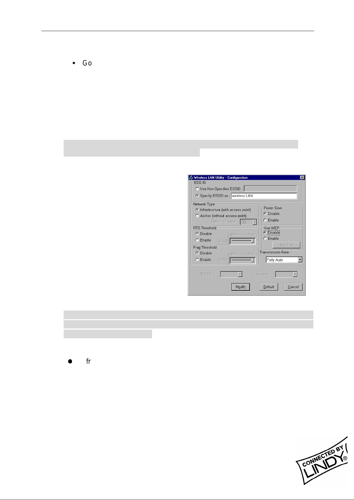
w
Go back to the main Utility window and click on [Network
Configuration]. Setup procedures are as follows:
1. ESSID denotes the assigned name for the designated wireless LAN. If the
PC Card ESSID is different from the Acc ess Point, you will not have
access to that wireless segment. Please note that by selecting [Use NonSpecif ied ESSID: ANY] the PC Card could be connected to other wireless
LAN with different ESSIDs. Therefore, ESSID set up is highly
recommended.
Example: Specify ESSID as: Wireless001.
Note: If t he ESSID of PC car d remains as default value ANY, t hen the PC
card could connect to other Access Points.
2. Select [Infrastructure] under ‘Network Type’
3. Using WEP: The default is
‘Disable’. If you require high
security in transmission, please
select the “Enable” i tem and click
[Key List]. In the Key1 entry
field, enter ten hexadecimal digits
(any combination of 0-9, a-f, or AF) preceded by the characters
“0x” (E.g. 0x11aa22bb33). Or
you may enter a five
alphanumeric character in the
range of “a-z”, “A-Z” and “0-9”
(E.g. MyKey). You can repeat
this step for other 3 W EP keys if
you wish. Select a WEP key as
an active key and then click OK to make the new settings to take affect.
Note: When you use WEP to communicate with the other wireless
devices, all the wireless devices in this network must have the same
WEP Key and active key. )
4. Upon completing steps 1~3, click on [Modify] to save altered values.
l
Infrastructure network configuration provides roaming to mobile users.
Multiple (at least 2) AP connection allows wireless clients to access
seamless wireless connection while moving freely within the coverage
area. To enable Extended Service Sets (ESS), all the wireless end
devices (11Mbps W ireless PC Card, AP, etc.) must be under the same
ESSID. The wireless client will automatically connect to the nearest
Access Point.
LINDY ELECTRONICS LIMI TED & LI NDY - ELEKTRONIK GMBH - FI RST EDI TION (APR 2001)
7
Page 8

English Manual
4. Utility Information
ESSID
Network Type
RTS Threshold
Network
Configuration
Fragmentation
Threshold
Use WEP
Power Save
Transmission
Rate
Site Survey Inspect channel quality for your site.
Diagnostic
Tools
Software Information:
The firmware of this wireless PC card is displayed on the utility main window.
Users could download and upgrade the most recent software version from the
supplier’s web site.
Link Qual ity Test Inspect the point-to-point data transmission quality
Access Point
Browser
Select t he wi r eless network group to join
(“ANY” is defaul t setting).
Select t he st ation operati on mode,
Ad-Hoc: (without Access Point) Infrastructure: (with
Access Point, default setting).
The threshold (number of by tes) for enabling
RTS/CTS handshake. Data with its frame size
larger than this value will perform the RTS/CTS
handshake. Value: 0~1500. For details please
refer t o the 11Mbps PC Card User Manual
The threshold (number of bytes) for the
fragm entation boundary. Data will be transmitted
in fragments which its size does not exceed this
value. Value: 256~2432. (Default setting :
“Disable”)
To hav e high security in data transmission.
(Defaul t setting : “Disable”)
Power management.
(Defaul t setting : “Disable”)
Select t he transmission rat e
(Defaul t setting : “Fully Auto”)
between two wireless LAN stations.
To browse all the active Access Points in this
environment.
LINDY ELECTRONICS LIMI TED & LI NDY - ELEKTRONIK GMBH - FI RST EDI TION (APR 2001)
8
Page 9

Deutsches Handbuch
Deutsches Handbuch
1. Einleitung
Das LINDY W-LAN 11 (Wireless LAN mit 11 Mb/s) bietet eine schnelle und
zuverlässige Lösung für kabellosen Netzwerkzugriff. Es ist kompatibel zum W-LAN
Standard IEEE802.11b und 802.11. Die Karte ist eine PCMCIA Typ II-Karte (16 Bit)
und funktioniert mit / in allen zum W-LAN Standard-konformen Funknetzwerken.
Es ist prädestiniert für den Einsatz in historischen Gebäuden, in denen keine
Kabelnetzwerke verlegt werden können, für die Anforderungen mobiler Einsatzorte
innerhalb eines Gebäudes oder um einen allgemeinen freien Netzwerkzugang (z.B.
Internet) in einer speziel len Umgebung (Universität, Hotel, etc.) zu schaffen.
Verbindungen können prinzipiell als Peer-to-Peer Verbindung (Ad-Hoc) zwischen
zwei Rechnern mit W-LAN PCMCIA Karte aufgebaut werden, zwischen Access
Points (Wireless Repeater) oder zwischen Access Point und Clients (Infrastruktur,
PCMCIA-Karte u.ä.). Der LINDY Access Point beherrscht die Roaming-Funktion, so
dass mit mehreren Access Points ein größeres Gebäude abgedeckt werden kann.
Die Reichweite ist sehr stark von den Gebäudegegebenheiten (Abschirmung durch
Wände, Träger, etc.) abhängig und kann unter günstigen Bedingungen bis 45m
reichen, im allgemeinen liegt die maximale Reichweite bei 15-25m.
Im Freien kann (ohne besondere Antennen) eine Reichweite von ca. 250m erreicht
werden.
Bitte beachten Sie, dass:
w
ein W-LAN leicht abgehört werden kann und nur mit aktivierter
Verschlüsselung (WEP) ein gewisses Maß an Sicherheit besteht !
w
ohne aktivierte Zugangsbeschränkung und ohne aktiviertes
Passwort sich jeder Nutzer mit IEEE802.11b W-LAN Karte in das
Netz einloggen kann !
Bitte beachten Sie die Aktivierungshinweise zu diesen Themen weiter hinten im
Handbuch.
1.1 Netzwerk-Kon figurationen
Die Karte funktioniert
unter Windows 95/98,
NT und 2000. Die
Unterstützung für
weitere Betriebssysteme ist in der Entwicklung. Software,
Treiber und Firmwareupdates stehen auf
www.lindy.com zum
Download bereit.
Mit der Karte kann ein
einfaches Ad-HocNetzwerk (Peer-to-peer,
Kabelloses Netz
Infrastruktur-Netzwerk
AccessPoint
Ad-hoc Netzwerk
Kabelnetzwerk
LINDY ELECTRONICS LIMI TED & LI NDY - ELEKTRONIK GMBH - FI RST EDI TION (APR 2001)
9
Page 10

Deutsches Handbuch
Kartenkommunikation untereinander) oder ein Infrastruktur-Netzwerk (mit W-LAN
Access Point) genutzt werden.
Im Ad-Hoc-Netz stehen die Merkmale des Basic Service Set zur Verfügung.
Im Infrastruktur-Netz stehen die Merkmale des Extended Basic Service Set zur
Verfügung, z.B. die Anbindung in ein kabel-gebundenes Netz über einen Access
Point.
2. Die W -LAN 11 PCMCIA-Karteninstallation
2.1. Lieferumfang
Stellen Sie bitte sicher, dass Sie die folgenden Dinge mit der Lieferung erhalten
haben:
w
Die LINDY W-LAN 11 PCMCIA Karte
w
Dieses Handbuch
w
Die Installati onsdiskette oder –CD
Sollte eines der genannten Teile fehlen, wenden Sie sich bitte an Ihren Fachhändler.
2.2. Installation unter Windows 95/98
w
Stecken Sie die PCMCIA Karte in den PCMCIA-Schacht des
ausgeschalteten Notebooks und schalten Sie das Notebook ein.
Windows wird die neue Hardware finden und den HardwareInstallationsassistenten starten.
w
Geben Sie als Quelle für die Treiber die beiliegende CD bzw. Floppy an.
w
Klicken Sie auf Beenden um die Installation zu komplettieren.
w
Nach erfolgreichem Abschluss der Installation starten Sie bitte Ihr
Notebook neu.
w
Zur Installation der Karten-Dienstprogramme starten Sie bitte von der
beiliegenden CD oder Diskette das Programm SETUP.EXE aus dem
Verzeichnis WLU und befolgen Sie die dort gegebenen Anweisungen.
w
Starten Sie danach das Utility Programm durch Doppelklick und führen
Sie die Konfigurationseinstellungen durch.
Bitte beachten Sie: Es ist ratsam, die PCMCIA-Karte vor dem Entfernen aus dem
Slot stets zu deaktivieren. Damit ist dem Betriebssystem die Möglichkeit gegeben,
sich aus dem Netzwerk auszuloggen, die Treiber sauber zu deaktivieren und die
Stromversorgung des entsprechenden PCMCIA-Schachtes abzuschalten.
3. Die Netzw erkinstallation
Falls Sie sich ein Netzwerk mit Access Points (Infratruktur-Netzwerk) aufbauen
möchten, können Sie Abschnitt 3.1 überspringen und direkt bei Abschnitt 3.2
weiterlesen.
LINDY ELECTRONICS LIMI TED & LI NDY - ELEKTRONIK GMBH - FI RST EDI TION (APR 2001)
10
Page 11

Deutsches Handbuch
3.1 Die Verwendung des Utility-Programmes zur Einrichtung eines Ad-HocNetzwerkes
Wenn das kabellose Netzwerk bereits eingerichtet wurde, genügt es schlichtweg, die
PCMCIA-Karte in den Schacht des laufenden Notebooks zu schieben, sodann kann
eine Verbindung aufgebaut werden. Andernfalls muß das Netzwerk mit den
folgenden Schritten eingerichtet werden:
w
Im Hauptfenster des Utility-Programmes klicken Sie bitte auf [Diagnostic
Tools], anschließend auf [Site Survey]. Dies deaktiviert kurzzeitig alle
Netzwerkverbindungen und zeigt die Signalqualität aller 14 verfügbaren
Kanäle mittels blauer Balken an. Suchen Sie einen Kanal mit guter Signalqualität für Ihr Ad-Hoc-Netzwerk aus.
w
Wieder im Hauptfenster des Programmes klicken Sie bitte auf [Network
Configuration]. Es erscheint nun der Hinweis: ‚Configure the Adapter’. Das
weitere Vorgehen läuft nun wie folgt ab:
1. ‚ESSID’ bezeichnet den Namen des von Ihnen eingerichteten /
einzurichtenden Netzwerkes. Weicht der unter ‚ESSID’ angegebene Name auf
den Clients voneinander ab, so werden diese nicht miteinander
kommunizieren. Beachten Sie bitte, daß durch die Einstellung ‚Use NonSpecif ied ESSID: non-speci’ der Rechner sich mit anderen möglicherweise in
Reichweite befindlichen Funknetzwerken verbinden, und somit heilloses
Chaos in der Netzwerkzuordnung verursachen könnte. Es ist daher sehr
ratsam unter ‚ESSID’ einen möglichst eindeutigen Namen zu vergeben, z.B.
<Ihr Name>.
Bitte beachten: Wenn auf nur einem System unter ‚ESSID’ ein Name vergeben
und auf allen anderen Systemen die Voreinstellung ‚non-speci’ beibehalten wird,
dann muß der Rechner, auf dem der Name vergeben wurde, unbedingt laufen,
damit überhaupt eine Kommunikation zustande kommen kann.
2. Wählen Sie [Ad-Hoc] unter ‚Network Type’ an, und geben Sie unter ‚Default
Channel’ die Nummer des Kanales ein, der bei der eingangs beschriebenen
Ermittlung der Signalqualität ausgesucht wurde. Es ist ein auf allen Rechnern
einheitlicher Kanal erforderlich, um eine Netzwerkgruppe aufzubauen.
3. ‚Use WEP’ (Wireless Encryption
Protocol) sollte aktiviert werden,
wenn Ihr Netzwerk grundlegenden
Sicherheitsanforderungen bei der
Datenübertragung genügen soll.
Um einen Sicherheitsschlüssel
anzugeben, klicken Sie auf [Key
List]. Das W EP arbeitet nur, wenn
es auf allen kabellosen Clients
Ihres Netzwerkes aktiviert wird.
Daher muß auch auf allen Clients
mit dem gleichen Verschlüsselungscode gearbeitet werden, d.h. wenn
LINDY ELECTRONICS LIMI TED & LI NDY - ELEKTRONIK GMBH - FI RST EDI TION (APR 2001)
11
Page 12

Deutsches Handbuch
beispielsweise unter ‚Key1’ ‚MyCar’ als Schlüssel eingegeben wird, muß
dieser auch auf allen anderen Clients unter ‚Key1’ gleichlautend sein. Es
können entweder ein fünf Zeichen langer alphanumerischer Code (‚A-Z’, ‚a-z’
und ‚0-9’, z.B. ‚MyKey’ oder ‚Alpha’) oder aber ein 10-stel liger hexadezimaler
Code (‚0-9’, ‚a-f’ oder ‚A-F’) mit vorangestelltem ‚0x’ (z.B. ‚0x11aabf21ce35’)
definiert werden. Es können bis zu 3 weitere Schlüssel angegeben werden.
Aktivieren Sie einen der 4 Schlüssel und klicken Sie [OK] um die Eingaben
wirksam werden zu lassen.
Bitte beachten Sie: Wenn Sie das WEP benutzen, müssen alle kabellosen
Netzwerk-Geräte, mit denen kommuniziert werden soll, den gleichen W EP-Code
und den selben Schlüssel aktiviert haben.
4. Nachdem die Schritte 1 – 3 vollzogen wurden, klicken
Sie bitte auf [Modify], um die geänderten Einstellungen zu sichern.
3.2 Die Einrichtung eines Infrastruktur-Netzwerkes
w
Im Hauptfenster des Utility-Programmes klicken Sie bitte auf [Diagnostic
Tools], anschließend auf [Access Point Browser]. Dies deaktiviert kurzzeitig
alle Netzwerkverbindungen und das folgende Fenster zeigt eine Übersicht
über alle in Funkreichweite befindlichen Access Points.
w
Wieder im Hauptfenster des Programmes klicken Sie bitte auf [Network
Configuration]. Es erscheint nun der Hinweis: ‚Configure the Adapter’. Das
weitere Vorgehen läuft nun wie folgt ab:
1. ‚ESSID’ bezeichnet den Namen
des von Ihnen eingerichteten/einzurichtenden
Netzwerkes. Weicht der unter
‚ESSID’ angegebene Name von
dem des Access Point ab, so
kann keine Kommunikation
zustande kommen. Beachten Sie
bitte, daß durch die Einstellung
‚Use Non-Specified ESSID: nonspeci’ der Rechner sich mit
anderen möglicherweise in
Reichweite befindlichen
Funknetzwerken verbinden, und
somit heilloses Chaos in der
Netzwerkzuordnung verursachen
könnte. Es ist daher sehr ratsam unter ‚ESSID’ einen möglichst
eindeutigen Namen zu vergeben, z.B. <Ihr Name>.
Bitte beachten: Wenn auf der Karte unter ‚ESSID’ die Voreinstellung ‚ANY’
beibehalten wird, dann kann der Rechner auch mit anderen eventuell
vorhandenen Netzwerken kommunizieren.
2. Markieren Sie [Infrastructure] unter ‚Network Type’
LINDY ELECTRONICS LIMI TED & LI NDY - ELEKTRONIK GMBH - FI RST EDI TION (APR 2001)
12
Page 13

Deutsches Handbuch
3. ‚Use W EP’ (Wireless Encryption Protocol ) sol lte akti vi ert werden, wenn Ihr
Netzwerk grundlegenden Sicherheitsanforderungen bei der Datenüber-
tragung genügen soll. Um einen Sicherheitsschl üssel anzu-geben, kl icken
Sie auf [Key List]. Das WEP arbeitet nur, wenn es auf allen kabellosen
Clients und Access Points Ihres Netzwerkes aktiviert wird. Daher muß
auch auf allen Clients und Access Points mit dem gleichen
Verschlüsselungscode gearbeitet werden, d.h. wenn beispielsweise unter
‚Key1’ ‚MyCar’ al s Schlüssel eingegeben wird, muß dieser auch auf allen
anderen Clients und Access Points unter ‚Key1’ gleichlautend sein. Es
können entweder ein fünf Zeichen langer alphanumerischer Code (‚A-Z’,
‚a-z’ und ‚0-9’, z.B. ‚MyKey’ oder ‚Alpha’) oder aber ein 10-stelliger
hexadezimaler Code (‚0-9’, ‚a-f’ oder ‚A-F’) mit vorangestelltem ‚0x’ (z.B.
‚0x11aabf21ce35’) definiert werden. Es können bis zu 3 weitere Schlüssel
angegeben werden. Aktivieren Sie einen der 4 Schlüssel und kli cken Sie
[OK] um die Eingaben wirksam werden zu lassen.
Bitte beachten Sie: Wenn Sie das WEP benutzen, müssen alle kabellosen
Netzwerk-Geräte, mit denen kommuniziert werden soll den gleichen W EP-Code
und den selben Schlüssel aktiviert haben.
4. Nachdem die Schritte 1 – 3 vollzogen wurden, klicken Sie bitte [Modify]
um die geänderten Einstellungen zu sichern.
w
Die Konfiguration als Infrastruktur-Netzwerk erlaubt den Anwendern sog.
Roaming. Ein Netzwerk aus mehreren (mindestens 2) Access Points gestattet
freie und übergangslose Mobilität zwischen den Funkabdeckungsbereichen
der einzelnen Aceess Points. Um sog. Extended Service Sets (ESS) zu
aktivieren, Access Points, die nur di e Aufgabe haben, den Funkabdeckungsbereich zu erweitern, müssen alle kabellosen Endgeräte (kabellose Clients,
Access Points etc.) unter der selben ESSID laufen. Der kabellose Client
verbindet sich automatisch mit dem Access Point, zu dem die qualitati v beste
Funkverbindung besteht. Weitergehende Informationen finden Sie auf
www.lindy.de in der Rubrik ‚Tips & More’
LINDY ELECTRONICS LIMI TED & LI NDY - ELEKTRONIK GMBH - FI RST EDI TION (APR 2001)
13
Page 14

Deutsches Handbuch
4. Software-I nformationen
ESSID
Network Type
RTS Threshold
Network Configuration
Fragmentation
Threshold
Use WEP
Power Save
Transmi ssion Rat e
Site Survey
Diagnostic Tools
Link Qual ity Test
Acces Point Browser
Wähl t die kabellose Netzwerkgruppe aus, der
der Client angeh ören sol l. (Werkseinstellung:
‚ANY’)
Wähl t den Arbeitsm odus aus: Ad- Hoc : ohne
Access Point,
Infrastructure: mit Access Point
(Werkseinstellung)
Schwellenwert (Anz ahl Bytes), für die
Aktivierung des RTS /CTS HardwareHandshake. Daten-Frames, die größer sind
als dieser Wert, werden per RTS /CTSHandshake übermi ttelt. Wert eber eich: 0 –
1500 (W erkseinstellung: ‚Disable’)
Schwellenwert (Anz ahl Bytes) f ür die
Fragment ierungsgrenze. Die Daten werden
in Bruchstücken übermit telt, die die Größe
dieses Wer tes nicht überschreiten.
Wer tebereich: 256 – 2432
(Werkseinstellung: ‚Disable’ )
Für Abhörsicherheit bei der
Datenübertragung. (Werkseinstellung:
‚Disable’)
Power-Management ( Werksei nstellung:
‘Disable’)
Wähl t die Datenübertragungsrat e aus.
Werkseinstellung: ’Fully Auto’
Ermi ttelt die Signalqualität der einzelnen
Kanäle für Ihren Standort.
Ermi ttelt die Qualität der Datenübertragung
zwischen zwei kabell osen St ationen.
Ermi ttelt alle akti vier ten und verfügbaren
Access Points der örtlichen Umgebung.
LINDY ELECTRONICS LIMI TED & LI NDY - ELEKTRONIK GMBH - FI RST EDI TION (APR 2001)
14
Page 15

Manuel en Français
Manuel en Français
1. Introduction
Le LINDY W-LAN 11 vous propose une solution rapide et fiable pour une
installation de réseau sans fil. Il est compatible avec le standard W-LAN
IEEE802.11b et 802.11. La carte d’accès est une carte PCMCIA Type II (16 Bits)
et fonctionnera avec tous les systèmes réseaux sans fil standards.
Il sera souvent utilisé dans les bâtiments assez anciens ou il est impossible
d’installer une structure de câblages réseaux et pour éviter les câbles trop
visibles, ou pour installer un réseau général sans fil (ex. Internet) avec accès
dans un environnement spécifique (université, école, hotel, etc).
En général il est possible d’installer une connexion réseau par paire (Ad-Hoc)
entre les ordinateurs par les cartes W-LAN PCMCIA, entre les points d’accès
(qui les laissent agir en tant que répéteurs), ou entre les points d’accès et l es
clients (Infrastructure). Le point d’accès LINDY supporte la foncti on de balayage,
qui autorise une plus grande surface d’émission en utilisant plus d’un point
d’accès. La portée d’un point d’accès dépend grandement des conditions et de la
structure du bâtiment (blindage des murs, épaisseurs, poteaux en acier etc).
Il est possible d’aller jusqu’à une portée de 45m sous de bonnes conditions;
Dans la plupart des cas on obtient des portées de 15 à 25m.
A l’extérieur des bâtiments, la portée peux être de 250m sans antennes spéciales
Veuillez notez que:
w
Il est possible de se connecter en toute liberté sur un réseau sans
fil W-LAN. Il est seulement possible d’avoir un certain niveau de
sécurité en activant l’option de cryptage.
w
Sans l’activation de cette option, toute personne disposant d’une
carte IEEE802.11b W-LAN pourra en théorie accéder au réseau
sans fil installé!
Pour plus d’informations sur l’activation de la sécurité, consultez la section de
configuration du réseau dans ce manuel.
1.1 Configuration du
réseau
La carte fonctionne
sous Windows 95/98,
NT et 2000. Le
support pour d’autres
systèmes d’exploitation est en cours de
développe-ment. Les
logiciels, pilotes et
mises à jour de BIOS
sont disponibles en
téléchargement sur www.lindy.com.
Rèseau sans fil
Réseau Ad-hoc
Réseau Infrastructure
Point d’accès
Réseau câblé
LINDY ELECTRONICS LIMI TED & LI NDY - ELEKTRONIK GMBH - FI RST EDI TION (APR 2001)
15
Page 16

Manuel en Français
La carte peut être utilisée dans un réseau ad-hoc (par communications paires par
paires avec cartes W -LAN) ou Infrastrucures réseaux (cartes W-LAN avec point
d’accès).
Dans un réseau ad-hoc, les fonctions basiques sont disponibles, dans une
Infrastructure réseau, vous pouvez accéder aux fonctions avancées,
Par exemple la connexion d’un réseau câblé par un point d’accès.
2. Utilitaire d’installation de la carte
2.1 Contenu de l’emballage
w
Carte PCMCIA 11Mbps Wireless x 1
w
Guide d’install ation rapide x 1
w
Logiciels et documentations sur le CD-ROM ou la disquette x 1
2.2 Utilitaire d’installation de la carte sous Windows 95/98
Insérez la carte PCMCIA 11Mbps Wireless dans un slot PCMCIA et lancez
Windows. Windows va détecter automatiquement le nouveau matériel et
Windows affichera “Nouveau matériel détecté”
Cliquez sur sui vant et insérez la disquette de pilote correspondante dans votre
lecteur .
Cliquez sur Suivant.
Lorsque le terme [Insérez le CD-ROM Win 95/98 dans votre lecteur, et cliquez
‘OK’] apparaît, entrez le chemin correspondant au lecteur puis validez par OK.
Cliquez Terminer pour compléter l’installation. Redémarrez W in 95/98.
Pour installer les utilitaires 11Mbps Wireless PC Card Utility, insérez le CD-Ro m
d’utilitaires fourni, allez dans le répertoire WLU et double-cliquez sur le
programme setup.exe.
Suiv ez le s in s t ru c t io n s à l’écran pour compléter l’installation, et double-cliquez sur
l’îcone Utility. L’interface de l’utilitaire va ensuite apparaître.
Note: Il est vivement recommandé de désactiver la carte PCMCIA avant de la
retirer de son slot. Cela permettra au système d’exploitation Windows de se
déconnecter du serveur réseau, désactiver correctement les pilotes et couper
l’alimentation du slot PCMCIA.
3. Utilisati on d’installation du réseau
3.1 Utilisation du programme de configuration pour mettre en place un réseau
Ad-Hoc
Si le réseau sans fil a déjà été configuré, connectez simplement les cartes
PCMCIA dans leurs emplacements. Dans le cas contraire, préparez un réseau
sans fil comme suit:
LINDY ELECTRONICS LIMI TED & LI NDY - ELEKTRONIK GMBH - FI RST EDI TION (APR 2001)
16
Page 17

Manuel en Français
w
Sur l’interface principale de l’utilitaire, c liquez sur [Diagn ostic tools] et cliquez
sur [Site Survey]. Ceci désactivera temporairement le réseau sans fil
et affichera la qualité de transmission sur chacun des 14 canaux. Veuillez
remarquer que les barres bleues représente la qualité de transmission d’un
canal. Sélectionner un bon canal pour le réseau Ad-Hoc.
w
De retour sur l’interface principale de l’utilitaire, cliquez sur [Network
Configuration] et la fenêtre “Configure the Adapter” va apparaître. Les
procédures de configuration se présentent comme suit:
1. ESSID dénote le nom
assigné pour le réseau
sans fil. Si l’ESSID diffère,
alors les clients ne
communiqueront pas entre
eux. Veuillez noter qu’en
sélectionnant [Use Non-
Specif ied ESSID: ANY], la
carte PCMCIA pourra se
connecter à d’autres
réseaux sans fil. C’est
pour cela que la
configuration des ESSID
est fortement recommandée. Exemple: Spécifiez ESSID en tant que : <Votre
Nom>.
Note: Dès lors que l’ESSID est régl é sur la carte PCMCIA 11Mbps Wireless, et le
reste des ESSID sont réglés par défaut ANY, alors la carte PCMCIA 11Mbps
Wireless doit être lancée en premier.
2. Sélectionnez [Ad-Hoc] sous ‘Network Type’, sélectionnez un bon canal.
Sélectionnez ensuite le canal sous [Ad-Hoc Default Channel].
Note: Sous Ad-Hoc, il est nécessaire d’avoir un seul et uni forme canal
pour établir et mettre en place un réseau sans fil.
3. Utilisez le WEP. Le réglage par défaut est ‘Disable’. Si vous souhaitez une
haute sécurité dans les transmissions, veuillez sélectionner l’option Enable
et sélectionnez [Key List]. Le WEP fonctionne avec tous vos clients en
simultané. Cependant, vous devez entrer la même clé entrée pour les autres
clients. Pour exemple, si vous entrez “MyCar” pour l a clé 1 pour votre carte
PCMCIA, entrez “MyCar” pour la cl é 1 pour tous les autres cl ients. Veuillez
vous référer à la page suivante pour la gestion des clés dans les
infrastructures WEP.
Note: Lorsque vous utilisez le WEP pour communiquer avec les autres clients,
tous les périphériques wireless connectés doivent avoir la même clé de
cryptage.
LINDY ELECTRONICS LIMI TED & LI NDY - ELEKTRONIK GMBH - FI RST EDI TION (APR 2001)
17
Page 18

Manuel en Français
4. Lorsque vous aurez terminé les étapes 1 à 3, cliquez sur [Modify] pour
sauvegarder les nouvelles valeurs.
3.2 Utilisation du programme de configuration pour mettre en place un réseau
Infrastructure
w
Sur la page principale de l’utilit air e , c liquez sur [Diagn ostic Tools] et cliquez sur
[Access Point Browser]. Ceci désactivera temporairement les communications
sans fil et l’utilitaire vous affichera les points d’accès disponibles.
w
Revenez sur la page principale de l’utilitaire et cliquez sur [Network
Configuration]. La configuration se met en place comme suit:
1. l’ESSID prend en compte le nom
donné au réseau sans fil. Si l’ESSID
de la carte PCMCIA est différent de
celui du point d’accès, vous n’aurez
pas accès à ce dernier. Veuillez
noter qu’en sélectionnant [Use Non-
Specified ESSID: ANY] la carte
PCMCIA pourra être connecté à
d’autres points d’accès en ayant un
ESSID différent. Cependant, le
réglage des ESSID est fortement
recommandé. Exemple: Spécifiez
ESSID en tant que: <Votre Nom>.
Note: Si l’ESSID de la carte PCMCIA
est réglée par défaut ANY, la carte
PCMCIA pourra être connectée sur tous
les réseaux sans fil existants.
2. Sélectionnez [Infrastructure] sous ‘Network Type’
3. Utilisation du WEP: Le réglage par défaut est ‘Disable’. S’il est nécessaire de
posséder une haute sécurité dans les transmissions, veuillez sélectionner la
fonction “Enable” et cl i quer [Key List]. Dans le champ Key1 , entrez 10 nombres
hexadécimal (combinaison 0-9, a-f, ou A-F) précédés par les caractères “0x” (Ex..
0x11aa22bb33). Ou vous pouvez également entrer un caractère alphanumérique
de l’ordre de “a-z”, “A-Z” and “0-9” (Ex. MyKey). Vous pouvez répéter cette étape
pour les trois autres clefs W EP si vous le souhaitez. Sélecti onnez un WEP en
tant que clef active et validez par OK pour que les changements prennent effet.
Note: Lorsque vous utilisez le protocole WEP pour communiquer avec les autres
périphériques sans fil, ces derniers doivent avoir la même clef WEP et clef active.
LINDY ELECTRONICS LIMI TED & LI NDY - ELEKTRONIK GMBH - FI RST EDI TION (APR 2001)
18
Page 19

Manuel en Français
4. Lorsque vous aurez terminé avec les étapes 1 à 3, cliquez sur [Modify] pour
sauvegarder les valeurs modifiées.
w
La configuration en Infrastructure réseau permet une facilité de connexion pour
les utilisateurs mobiles. Des connexions AP multiples (Min. 2) permet aux
utilisateurs mobiles d’utiliser leurs périphériques sans fil tout en se déplaçant
dans la zone d’émission. Pour activer le kit d’extension (ESS), tous les
périphériques sans fil (Carte PCMCIA 11Mbps Wireless, Points d’accès, etc.)
doivent avoir le même ESSID. Le client concerné se connectera
automatiquement au point d’accès le plus proche.
4. Informations concernant l’utilitaire
Network ConfigurationESSIDSélectionne le réseau sans fil à rejoindre (“ANY” est le
réglage par défaut).Network TypeSélectionne le mode opératoire de la stati on , AdHoc: (sans point d’accès) Infrastructure: (avec point d’accès, par défaut).RTS
ThresholdIndique le nombre d’octets pour activer RTS/CTS handshake. Les données
avec une largeur de page supérieure à cette valeur va effectuer le RTS/CTS
handshake. Value: 0~1500. Fragmentation Threshold Indique le nombre d’octets
pour la valeur fragmentation boundary. Les données vont être transmises en
fragments dont la taille ne doit pas excéder la valeur donnée. Valeur: 256~2432.
(réglage par défaut : “Disable”)Use WEPPossibilité d’avoir une haute sécurité au
niveau du transfert de données. (réglage par défaut : “Di sable”)Power
SaveEconom ie d’énergie. (réglage par défaut : “Disable”)Transmission RateSélection
du taux de transfert (réglage par défaut : “Fully Auto”)Diagnostic ToolsSite
SurveyInspection de la qualité du canal de votre site.Link Quali ty TestInspection de
la qualité de la transmission point-to-point entre deux stations wireless LAN.Access
Point Browser. Pour parcourir tous les points d’accès dans l’environnement actif.
LINDY ELECTRONICS LIMI TED & LI NDY - ELEKTRONIK GMBH - FI RST EDI TION (APR 2001)
19
Page 20

Manuel en Français
ESSID
Network Type
RTS Threshold
Network
Configuration
Dia gnostic Tools
Fragmentation
Threshold
Use WEP
Power Save
Transmission Ra t e
Site Survey Inspection de la qualité du canal de votre site.
Link Quality Test Inspection de la qualité de la transmissio n po int-to -po int
Access Point
Browser
Installation et mise à jour logicielle:
La version du BIOS de la carte PCMCIA sans fil est affichée sur page principale de
l’utilit air e d e c onfig ur at ion . Le s u tilis at eur s p ou rr on t t élécharger et mettre à jou r la ve rs io n la
plus récente du logiciel pour le réseau sans fil.
Sélectionne le réseau sans fil à r ejoindre (“ANY” est le
réglage par défaut).
Sélectionne le mode opératoire de la station , Ad-Hoc:
(sans point d’accès)
Infrastructure: (avec point d’accès, par défaut).
Indique le nombre d’octets pour activer RTS/CTS
handshake. Les données avec une largeur de page
supérieure à cette valeur va effectuer le RTS/CTS
handshake.
Value: 0~1500
Indique le nombre d’octets pour la valeur fragmentation
boundary. Les données vont être transmises en
fragments dont la taille ne doit pas excéder la valeur
donnée.
Valeur: 256~2432.
(réglage par défaut : “Disable”)
Possibilité d’avoir une haute sécurité au niveau du
transfert de données.
(réglage par défaut : “Disable”)
Economi e d’énergie.
(réglage par défaut : “Disable”)
Sélection du taux de transfert
(réglage par défaut : “Fully Auto”)
entre deux stations
wireless LAN.
Pour parcourir tous les points d’accès dans
l’environnement actif.
LINDY ELECTRONICS LIMI TED & LI NDY - ELEKTRONIK GMBH - FI RST EDI TION (APR 2001)
20
Page 21

Manuale Uso
Manuale Uso
1. Introduzione
Il LINDY W -LAN 11 fornisce una rapida ed affidabile Soluzi one per l’accesso a
reti wireless. Esso è compatibile con l o standard W-LAN IEEE802.11b e 802.11.
La scheda è una PCMCIA di Tipo II (16 Bit) capace di operare con tutti gli
standard di rete wireless W-LAN.
E’ particolarmente consigliata ad esempio in edifici Storici dove non vi è la
possibilità di installare cavi di rete; per connessioni mobili fra gli edifici, o per
creare una rete generale senza cavi (ad es. Internet) con accessi, in specifici
ambienti (università, scuole, alberghi, etc).
Generalmente è possibil e creare un collegamento in una rete punto a punto (AdHoc) tra un computer in cui è installata la scheda PCMCIA W -LAN, ed i punti di
accesso (che forniscono i ripetitori wireless), o tra i punti di accesso ed i client
(Infrastruttura). Il LINDY access point supporta funzionalità di roaming, che
consentono una maggiore area di copertura in modo da usare uno o più punti di
accesso. La capacità di un punto di accesso dipente principalmente dalle
condizioni dell’edificio (lo schema dei muri, pilastri e travi d’acciaio, etc.). Può
essere fino a 45 metri in buone condi zioni; nell a maggior parte dei casi il valore
varia da 15 a 25 metri. Fuori dagl i edifi ci, la suddetta capaci tà può raggiungere i
250 metri senza l’impiego di antenne speciali.
Prego notare:
w
E’ possible visualizzare la trasmissione in una W-LAN. Solo
abilitando il criptaggio, si ha un certo grado di sicurezza.
w
Senza aver attivato restrizioni di accesso e funzioni di password
ognuno provvisto di una scheda IEEE802.11b W-LAN, potrebbe
teoricamenteavere accesso alla rete, all’interno dell’area!
Per istruzioni su come attivare le funzioni di sicurezza, vedere la sezione
‘installazione della rete’, in questo manuale.
1.1 Configurazione Rete
Questa scheda lavora sotto Windows 95/98, NT e 2000. Il supporto di altri sistemi
operativi è sotto sviluppo. Software, driver e aggiornamenti dei firmware sono
disponibili tramite download da www.lindy.com.
La scheda può operare in una rete ad-hoc (comunicazione punto a punto tra
computer provvisti delle schede W - LAN) o in infrastrutture di reti (insi eme con un
W-LAN access point).
In una rete ad-hoc la funzione dei servizi disponibili è quella di base, in una
infrastruttura di rete i servizi disponibili possono essere estesi ad un più ampio
set, ad esempio la connessione ad un cavo di rete tramite un punto di accesso.
LINDY ELECTRONICS LIMI TED & LI NDY - ELEKTRONIK GMBH - FI RST EDI TION (APR 2001)
21
Page 22

Manuale Uso
La scheda per
PC 11Mbps
Wireless è una
PCMCIA
IEEE802.11/802
.11b-compatibile
Tipo II DSSS
wireless LAN
adapter. Essa
supporta
completamente
reti wireless
sotto Windows
95/98, e NT 4.0.
La scheda per PC 11Mbps Wi reless può operare in modo Ad-Hoc e in ambienti con
configurazioni di reti. La modalità Ad-Hoc permette di utilizzare la scheda per PC
11Mbps Wireless per collegamenti tra utenti ed una Serie di Servizi di Base (i.e.,
modalità punto-a-punto, senza punti di accesso). La modalità della struttura permette
di util izzare la scheda per PC 11Mbps W ireless per collegamenti tra utenti ed una
Serie di Servizi Avanzati (i.e., connessione punto-a-punto).
Rete Wireless
Rete Ad-hoc
Infrastruttura di Rete
Punto di Accesso
Cablaggio Rete
2. Installazione scheda per PC 11Mbps W i reless e Utilità
sotto Window s 95/98
2.1 Contenuto Confezione
w
Scheda PC 11Mbps Wireless x 1
w
Guida all’Installazione Rapida x 1
w
Software e Documentazione su CD-ROM o Disco Floppy x 1
2.2 Installazione sotto Windows 95/98
Inserire la scheda per PC 11Mbps W i reless nel l o slot PCMCIA ed avviare W i ndows.
Wi ndows rileverà automaticamente un nuovo componente hardware e l’install azione
guidata di Windows mostrerà “Trovato Nuovo Componente Hardware”
Cliccare su Avanti ed inserire il driver corrispondente al software su CD-ROM o
floppy nell’apposito driver. Cliccare su Avanti.
Una volta [Inserito il CD-Rom Win 95/98 nell’apposito driver, quindi cliccato ‘OK’]
apparsa la finestra, inserire il percorso corrispondente al driver appropriato e cliccare
OK.
Cliccare Fine per completare l’install a zione. Riavviare Win 95/98.
Installare le Utilità della scheda per PC 11Mbps Wirel ess, i nserire i l CD-ROM o altro
disco driver dell e stesse. Aprire la cartella WLU e doppio click sull’icona setup.exe.
Seguire le istruzioni a video per completare l’install azi one del le utilità, quindi doppi o
click sull’icona delle Utilità. Apparirà l’interfaccia delle utilità e sarà allora possible
effettuare la configurazione.
LINDY ELECTRONICS LIMI TED & LI NDY - ELEKTRONIK GMBH - FI RST EDI TION (APR 2001)
22
Page 23

Manuale Uso
Note: E’ sempre consigliabile disabilitare la scheda PCMCIA prima di rimuoverla
dallo slot. Questo permetterà al Sistema Operativo Windows di sconnettersi dai
servizi di rete, disabilitando il relativo driver e sconnettendo l’alimentazione dallo slot
della scheda PC.
3. Installazione di Rete
3.1 Utilizzo delle Utilità installate su una Rete Ad-Hoc
Se la rete LAN wireless è già installata, col legare semplicemente la scheda per PC
11Mbps Wireless. Altrimenti, installare una rete wireless seguendo i seguenti punti:
Sull’utilità principale, cliccare su [Strumenti di Diagnostica] e quindi su [Zona
Osservazione]. Questo disabiliterà temporaneamente la rete wireless e mostrerà la
qualità del canale su 14 livelli. Prego notare che la barra blu rappresentante la qualità
del canale. Selezionare un canale buono per la Rete Ad-Hoc.
1. Tornare sull’utilità principale
connessa, cliccare su [Configura-
zione di Rete] e apparirà la
finestra “Configura l’adattatore”.
Procedere all’installazione come
segue:
Denominazione ESSID per
assegnare un nome alla LAN
wireless. Se l’ESSID è differente,
allora i client wireless non
comunicheranno tra loro. Prego
notare quello da selezionare [Uso
Non-Specificato ESSID: ALCUNO], la scheda PC deve essere connessa
alle altre LAN wireless. Perciò l’installazione dell’ESSID è particolarmente
raccomandata. Esempio: Specificare ESSID come : <Il Vo stro nome>.
Note: Una volta i mpostata la scheda per Pc 11Wirel ess, il valore della ESSID
rimane di default, allora la scheda per PC Wireless 11Mbps deve essere avviata
per prima.
2. Selezionare [Ad-Hoc] sotto ‘Tipo di Rete’, selezionare un buon canale come
indicato nel punto 1. Selezionare il canale sotto [Canale di Default A d-Hoc].
Note: Sotto Ad-Hoc, richiederebbe un solo, canale uni forme da abilitare per la
trasmissione wireless in un gruppo della rete.
3. Utilizzare W EP. Di default è ‘Disabilitato’. Se è richiesta alta sicurezza nell a
trasmissione, si prega di selezionare Abilita e selezionare [Lista Chiave].
WEP lavorano in concomitanza con tutti i clients. Pertanto è necessario
inserire la stessa chiave per gli altri client. Per esempio, se si vuole accedere
“La MiaMacchina” nella chiave 1 della scheda del PC, entrando in “La
LINDY ELECTRONICS LIMI TED & LI NDY - ELEKTRONIK GMBH - FI RST EDI TION (APR 2001)
23
Page 24

Manuale Uso
MiaMacchina” si accede a tutti gli altri cl ient. Si prega di riferirsi alla sezione
Infrastrutture per le chiavi WEP inserite alla pagina seguente.
Note: Quando si uti lizza WEP per comunicare con tutti gli al tri client wireless,
tutti i dispositivi wireless in questa rete devono avere alcune chiavi di criptaggio.
4. Completare i punti 1~3, cliccare su [Modifica] salvando i nuovi valori.
3.2 Utilizzo delle Utilità per l’installazione su una Infrastruttura di Rete
w
Sull’interfaccia dell’Utilità principale, cliccare su [Strumenti di Diagnostica] e
quindi cliccare su [Punti di Accesso Browser]. Questo disabiliterebbe
temporaneamente la connessione wireless e mostrerebbe conseguentemente lo
stato di tutti i punti di accesso.
1. Tornare alla finestra dell’Utilità principale e cliccare su [Configurazione di
Rete]. Seguire le procedure di installazi one come segue:
ESSID denomina il nome per l’assegnazione della LAN wireless. Se la scheda
PC ESSID è differente dal Punto di Accesso, non è possibil e avere accesso a
quel tratto di wireless. Si prega di riferirsi alla selezione [Uso Non-Specificato
ESSID: ALCUNO] la scheda PC poteva essere connessa ad un’altra LAN con
differente ESSID. Perciò, l ’installazione ESSID è altamente raccomandata.
Esempio: Specificare ESSID come: <Il Vostro nome>.
Note: Se la scheda per PC rimane con i valori di default, allora la scheda PC potrà
connettere altri Punti di Accesso.
2. Selezionare [Infrastrutture] sotto ‘Tipo di Rete’
3. Utilizzare WEP. Di default è
‘Disabilitato’. Se è richiesta alta
sicurezza nella trasmissione, si
prega di selezionare Abilita e
selezionare [Lista Chiave]. Nella
chiave1 entrare dando un invio,
digitare dieci cifre esadecimali
(combinazione di 0-9, a-f, oppure
A-F) precedute da dei caratteri
“0x” (E.g. 0x11aa22bb33). Oppure
è possible inserire cinque caratteri
alfanumerici nella serie “a-z”, “A-
Z” e “0-9” (E.g. La MiaChiave). E’
possibile ripetere questo punto
per altre 3 chiavi WEP se lo si
desidera. Selezionare una chi ave
WEP come una chiave attiva e
quindi cliccare OK, effettuare i nuovi settaggi perchè abbiano efficacia.
LINDY ELECTRONICS LIMI TED & LI NDY - ELEKTRONIK GMBH - FI RST EDI TION (APR 2001)
24
Page 25

Manuale Uso
Note: Quando si uti lizza W EP per comunicare con tutti gli altri client wireless, tutti i
dispositivi wireless in questa rete devono avere alcune chiavi WEP attive.
4. Completare i punti 1~3, cliccare su [Modifica] salvando i nuovi valori.
w
Configurazione Infrastruttura di rete per provvedere ad una roaming degli utenti
mobili. Multiplo (almeno 2) collegamento AP permette agli utenti una connessione
wireless, senza collegamenti con cavi, liberamente all’interno dell’area coperta.
Abilitare Extended Service Sets (ESS), tutti i dispositivi wireless (Scheda PC
Wi reless 11Mbps, AP, etc.) devono essere sotto il medesimo ESSID. Gli utenti
wireless saranno automaticamente connessi al Punto di Accesso più vicino.
4. Utility delle Informazioni
ESSID
Tipo di Rete
Limite RTS
Configurazione
Rete
Strumenti di
Diagnostica
Limite di
Frammentazione
Uso WEP
Salvataggio
Alimentazione
Tipo
Trasmissione
Luogo
d’Osservazione
Verifica Qualità
Collegamento
Punti di A ccesso
Browser
Software Information:
La versione del firmware di questa scheda PC wireless è mostrata nella finestra delle
utilità principali. Gli utenti possono scaricare ed aggiornare la versione più recente
del software dal sito web del fornitore oppure fare riferimento alla vendita per
ricevere informazioni sugli ultimi software.
Seleziona il gruppo della rete wirel ess collegato
(“ALCUNO” è il settaggio di default).
Seleziona la modalità dello stato di operativi tà,
Ad-Hoc: (senza Punt o di Accesso) Infr astr uttura: (con
Punto di Acc esso, sett aggio di def ault).
Il limite (numero di byte) per abilitare l’allaccio
RTS/CTS. Qualsiasi valore superiore a questo limite,
andrà sempre al limite RTS/CTS. Valole: 0~1500. Per
dettagli si prega di riferi r si al manuale d’uso della
scheda per PC 11Mbps
Il limite (numero di byte) per la c onc lusione della
frammentazione. Dati che saranno trasmessi nella
frammentazione la cui dimensione non dovrà
eccedere dal valore. Valore: 256~2432. (Settaggi o di
Default: “Disabilitato”)
Per av er e un alta sicurezz a nella trasm issione dei
dati.
(Settaggi o di Defaul t: “Disabilitato”)
Gestione alimentazione.
(Settaggi o di Defaul t: “Disabilitato”)
Selezionare il tipo di trasm issione
(Settaggi o di Defaul t: “Totalmente Automatico”)
Controllo della qualità del canale per i l proprio l uogo.
Controllo della qualità della trasm issione punto-apunto tra due stazi oni LAN wireless.
Tutti i Punti di Accesso del Browser in questa zona
sono attivi.
LINDY ELECTRONICS LIMI TED & LI NDY - ELEKTRONIK GMBH - FI RST EDI TION (APR 2001)
25
Page 26

Appendix
Appendix
1.Declaration of Conformity
EG-Konformitätserklärung gemäß dem Gesetz über Funkanlagen
und Telekommunikationsendeinrichtungen (FTEG)
und der Richtlinie 1999/5/EG (R&TTE)
EC Declaration of C onformity in accordance with the Radio and Telecommunications Terminal Equipment Act (F TEG)
and Directi ve 1999/5/EC (R&TTE Directive)
Wir erklären, dass das folgend bezeichnete Produkt
We declar e that the following designated pr oduct
LINDY WLAN PCMCIA Card Ar t.Nr.: 52000
(Funkanlage Geräteklasse 2 / Radio Equi pment, Equipment Class 2 )
bei bestimmungsgemäßer Verwendung den grundlegenden Anforderungen des § 3 und den übrigen einschlägigen Bestimmungen des FTEG (Artikel 3 der R&TTE) entspricht.
complies with the essential requirements of §3 and the other relevant provisions of the FTEG (Arti cle 3 of the R&TTE
Directive), when used for its intended purpose.
Das Produkt entspricht den Anforderungen der Richtlinien 1999/5/EG (R&TTE), 73/23/EG (Niederspannungsrichtlinie) und 93/68/EG. Die Bewertung der Konformität des Produktes
bezüglich der Anforderungen der Elektrischen Sicherheit erfolgte basierend auf folgendem Standard:
The product complies with the requirements of R&TTE Directive 1999/5/EEC, the European Community Di rectives 73/23/EEC and 93/ 68/EEC. Assessment of compliance of the product with the requir ements relating to Elect r ical Safety was based on the following
standard:
Das Produkt entspricht Anforderungen den Richtlinie 1999/5/EG (R&TTE) und 89/336/EG (EMV, Elektromagnetische Verträglichkeit). Die Bewertung der Konformität des Produktes
bezüglich der Anforderungen der Elektromagnetischen Verträglichkeit erfolgte basierend auf folgenden Standards:
The product complies with the essential protection requirements of R&TTE Directive 1999/5/EEC and of the Council Direc tive 89/336/EEC. Assessment of c ompliance of the product with the requirements relating to Electromagnetic Compatibilty was based on the
following standard:
ETS 300 826 (+A1):1997, EN50081-1:1992, EN50082-1:1992
Das Produkt entspricht den grundlegenden Anforderungen der Richtlinie 1999/5/EG (R&TTE) bezüglich der Maßnahmen zur effizienten Nutzung des Funkfrequenzspektrums. Die
Bewertung der Konformität des Produktes (Klasse 2.7) bezüglich der Anforderungen der Funkfrequenzenbelange (Maßnahmen zur effektiven Nutzung des Funkspektrums)
erfolgte basierend dem Anhang IV der Richtlinie 1999/5/EG und auf folgendem Standard:
The product complies with the essential protection requirements of R&TTE Directive 1999/5/EEC on the appr oximation of the laws of the Member States relating to Radio Spectrum Matters. Assessment of compliance of the product (class 2.7) with the requirements
relating to Radio Spectrum Matters was based on Annex IV of the Directive 1999/5/EC and the following standard:
______________________________________________________________________
Einschränkungen / Limitations
Das genannte Produkt darf nur in folgenden Mitgliedsländern der EG ver trieben und in Betrieb genommen werden:
Deutschland, Italien, Östreich, England, Belgien, Niederlande, Luxemburg.
The product may only be sold and brought into use in the following memebr countries of the EC:
Germany, Italy, Austria, Great Britain, Belgium, Netherlands, Luxemburg.
In folgenden Ländern der EG darf das Produkt nicht in Betrieb genommen werden:
In the following member countries of the EC the product may NOT be brought into use :
Frankreich / France , Spanien / Spain / Espagne.
Diese Einschränkungen beruhen maßgeblich auf den vom Gerät verwendeten Funkfrequenzen, die bei Ausfertigung dieser Konformitätserklärung NICHT europaweit
einheitlich harmonisiert und nutzbar waren/sind.
These limitations are due to the radio frequency range used by the unit that are not yet harmonized throughout all countries of the EC.
Diese Erklärung wird verantwortlich für
LINDY Elektronik GmbH
Markircher Straße 20
68229 Mannheim
Germany
EN 60950 : 1997
ETS 300 328 : 1997
abgegeben durch
Jürgen Lindenberg
Geschäftsführer
Mannheim, 19.Feb. 2001
............................................
LINDY ELECTRONICS LIMI TED & LI NDY - ELEKTRONIK GMBH - FI RST EDI TION (APR 2001)
26
Page 27

Appendix
EG-Konformitätserklärung gemäß dem Gesetz über Funkanlagen
und Telekommunikat ionsendeinrichtungen (FTEG)
und der Richtlinie 1999/5/EG (R&TTE)
Wir erklär en, dass das folgend bezeichnete Produkt
We dec lare t hat the f ollo wing designat ed product
EC Declaration of C onformity in accordance with the Radio and Telecommunications Terminal Equipment Act (F TEG)
and Directi ve 1999/5/EC (R&TTE Directive)
LINDY WLAN PCMCIA Card Art.Nr.: 52002
bei bestimmungsgemäßer Verwendung den grundlegenden Anforderungen des § 3 und den übrigen einschlägigen Bestimmungen des FTEG (Artikel 3 der R&TTE) entspricht.
complies with the essential requirements of §3 and the other relevant provisions of the FTEG (Arti cle 3 of the R&TTE
Directive), when used for its intended purpose.
Das Produkt entspricht den Anforderungen der Richtlinien 1999/5/EG (R&TTE), 73/23/EG (Niederspannungsrichtlinie) und 93/68/EG. Die Bewertung der Konformität des Produktes
bezüglich der Anforderungen der Elektrischen Sicherheit erfolgte basierend auf folgendem Standard:
The product complies with the requirements of R&TTE Directive 1999/5/EEC, the European Community Di rectives 73/23/EEC and 93/ 68/EEC. Assessment of compliance of the product with the requir ements relating to Elect r ical Safety was based on the following
standard:
(Funkanlage Geräteklasse 2 / Radio Eq ui pment, Equipment Class 2 )
Das Produkt entspricht Anforderungen den Richtlinie 1999/5/EG (R&TTE) und 89/336/EG (EMV, Elektromagnetische Verträglichkei t).
Die Bewertung de r Konformität des Produktes bezüglich der Anforderunge n der Elektromagnetischen Verträglichkeit erfolgte
basierend auf folgenden Standards:
The product complies with the essential protection requirements of R&TTE Directive 1999/5/EEC and of the Council Direc tive 89/336/EEC. Assessment of c ompliance of the product with the requirements relating to Electromagnetic Compatibilty was based on the
following standard:
Das Produkt entspricht den grundlegenden Anforderungen der Richtlinie 1999/5/EG (R&TTE) bezüglich der Maßnahmen zur effizienten Nutzung des Funkfrequenzspektrums. Die
Bewertung der Konformität des Produktes (Klasse 2.7) bezüglich der Anforderungen der Funkfrequenzenbelange (Maßnahmen zur effektiven Nutzung des Funkspektrums)
erfolgte basierend dem Anhang IV der Richtlinie 1999/5/EG und auf folgendem Standard:
The product complies with the essential protection requirements of R&TTE Directive 1999/5/EEC on the appr oximation of the laws of the Member States relating to Radio Spectrum Matters. Assessment of compliance of the product (class 2.7) with the requirements
relating to Radio Spectrum Matters was based on Annex IV of the Directive 1999/5/EC and the following standard:
______________________________________________________________________
ETS 300 826 (+A1):1997, EN50081-1:1992, EN50082-1:1992
Einschränkungen / Limitations
Das genannte Produkt ist für die Nutzung und den Vertrieb in folgenden Mitgliedsländern der EG vorgesehen:
The pro duct is designated for use and dis tr ibution i n the fo ll owing member cou ntries of the EC:
Frankreich / France
In folgen den Ländern der EG darf das Produkt nic ht in Betr ieb genommen w erden:
In the following member countries of the EC the product may N O T be brought into use :
Spanien / Spain / Espagne.
Diese Einschränkungen beruh en maßgeblich auf den v om Gerät ver w endeten F u nkfrequenzen, die bei Ausf ertigung dieser Konfor mitätserklärung NICHT europaweit einheitlich harmonisiert
und nutzbar waren/sind.
These limitations are due to the radio frequency range used by the unit that are not yet harmonized throughout all countries of the EC.
Diese Erklärung wird verantwortlich für
LINDY Elektronik GmbH
Markircher Straße 20
68229 Mannheim
Germany
abgegeben durch
Jürgen Lindenber g
Geschäftsführer
Mannheim, 19 . FEB 2001
EN 60950 : 1997
ETS 300 328 : 1997
LINDY ELECTRONICS LIMI TED & LI NDY - ELEKTRONIK GMBH - FI RST EDI TION (APR 2001)
27
Page 28

Appendix
2.Technical Specifi cati ons
w
PCMCIA NIC Card, Type II, Plug and Play PC Card 2.1 Compliant.
w
compatible to the wireless LAN standard IEEE802.11/802.1b
w
comp atible to all products of other suppliers that comply with the wireless LAN
standard IEEE802.11/802. 11b
w
compatible also with wireless LAN hardware that only supports slower data
transfer rates (e.g. 1 Mb/s or 2 Mb/s)
w
Data transfer rate wireless 11, 5.5, 2 or 1 Mb/s, autosensing
w
40-bit data encryption with WEP
w
LED Indicators for link and power
w
Power consumption: TX power consumption: <350mA; RX power
consumption: <250mA; Sleep Mode power consumption: 17mA
w
Output power: 13dbm (PA output power 18dB)
w
Uses Direct Sequence Spread Spectrum (DSSS) technology
w
Uses the 2.4 GHz international ISM band.
w
Operating frequency : 2.412-2.472 GHz (Eur ope ETSI)
2.457-2.472 GHz (France)
w
13 channels ( France: 4 channels ) to be assigned for the wireless connection
w
Usable in peer to peer (w/o acces point) or infrastructured ( including access to
a wire d et he rnet) network environments
w
Modulation: CCK (11Mbps, 5.5Mbps), DQPSK (2Mbps), DBPSK (1Mbps)
w
Ma ximum range up to 45 m insid e ( de pendin g on the lo cal b uild ing co nditions)
and up to 400m outside of buildings
Range Coverage:
Sensitivity:
11M 460 feet = 140m (In Open
Environment)
5.5M 656 feet = 200m
2M 885 feet = 270m
1M 1311 feet = 400m
@PER<0.08
11Mbps<-83dBm
5.5Mbps<-86dBm
2Mbps<-89dBm
1Mbps<-91dBm
Environment Informati on
Working Temperature:
LINDY ELECTRONICS LIMI TED & LI NDY - ELEKTRONIK GMBH - FI RST EDI TION (APR 2001)
Storage Temperature:
Humidity (non-condensing):
Size and Weight:
113mm L x 54mm W x 5.3mm H
Compact Size Weight < 50g
0 ~ 55°C
-20~ 80°C
5~90%
PCMCIA type II
(Antenna included)
28
 Loading...