

Page 1

Wireless LAN - 11
Access Point
Short Manual English
Kurzhandbuch Deutsch
Manuel condensé Français
Estratto del Manuale Italiano
LINDY Art. Nr. 52020 Version Europe: NOT FOR USE IN France + Spain
LINDY Art. Nr. 52022
© LINDY ELECTRONICS LIMITED & LINDY-ELEKTRONI K GMBH - FIRST EDITION (APR 2001)
Version Française
Page 2

English Short Manual
1. Introduction
The LINDY W-LAN 11 (Wireless LAN with 11 Mb/s) offers a quick and reliable solution for
professional wireless networking. It is compliant with standards IEEE802.11b and 802.11.
and is ideally suited for use in historic buildings where no structured cabling can be installed, for
the request of mobile moving network access inside a building, and for free and open network
access (Internet) i.e. in universities, hotels etc.
Connections can be established as peer-to-peer (i.e. notebooks with W-LAN PCMCIA card),
between access points (wireless repeater) or between access point and client (PCMCIA card or
similar). The LINDY Access Point offers a roaming function so that even larger buildings can be
covered by the wireless LAN.
The maximum transmission distance between two points largely depends on the local
environment, building construction and the shielding of walls, ceilings and metal construction
parts of the building. Under ideal conditions the transmission covers a range up to 45m, in most
cases the distance is between 15 and 25m. In the free environment without reflections a
distance of 250m may possibly be achieved.
Please note:
a) A wireless LAN can easily be accessed from unauthorised persons. Only when
encryption is activated is there relative security against this!
b) Without activated Access Control and without password every user with wireless
LAN IEEE802.11 compatible hardware can log into the wireless LAN!
Please refer to the detailed description given later in this Manual.
Wireless Infrastructure
In a wireless infrastructure, the W-LAN 11 acts as a bridge. The Access Point connects the
wireless clients together and acts as a central point for all wireless communications. This would
increase efficiency of the communications since the wireless adapters do not need to be within
direct range of each other.
2. Hardware Installation
Before you begin make sure that the following items are enclosed:
w
The LINDY W-LAN 11 Access Point
w
The power adaptor
w
The Installation disk or CD
If anything is missing or damaged please contact your dealer.
Placement of the Access Point
Before installation determine the best locati on for the AP. The location should be central,
relative to the area being covered by the W-LAN. It should be located some distance from any
highly shielding elements of the building. The AP can either be placed on a flat surface or
mounted vertically on a wall.
Connections
Connect the MDI port of the AP to your Ethernet hub or connect the MDI-X port to a computer
or workstation using straight through STP/UTP cable. Connect the power adaptor to the AP and
to the mains supply.
Page 3
English Short Manual
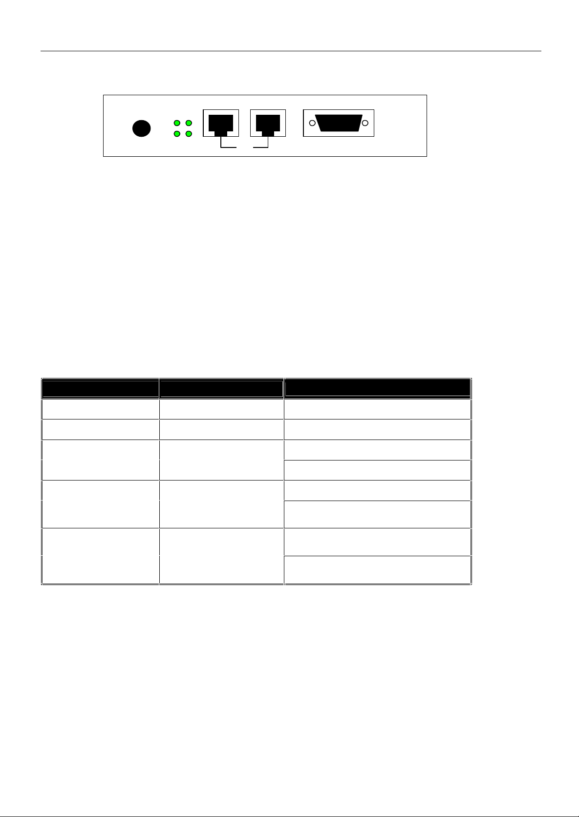
Rear view of your W-LAN 11 Access Point:
Power: Connect the power adaptor here.
MDI: RJ-45 connector for Ethernet Hub with10BaseT or 100BaseTX.
MDI-X RJ-45 connector to connect a computer or workstation, you can only use one of
RS-232 Console port to configure and program the Access Point
LED’s status display for the wired Ethernet
After correct installation of all connections to the wired LAN the Link LED should always light
green when the hub or the workstation/computer is switches on.
The top panel of the W-LAN 11 Access Point
POWER MDI MDI-X RS-232
100M TX
Link
RX
OR
the MDI / MDI-X marked connectors!
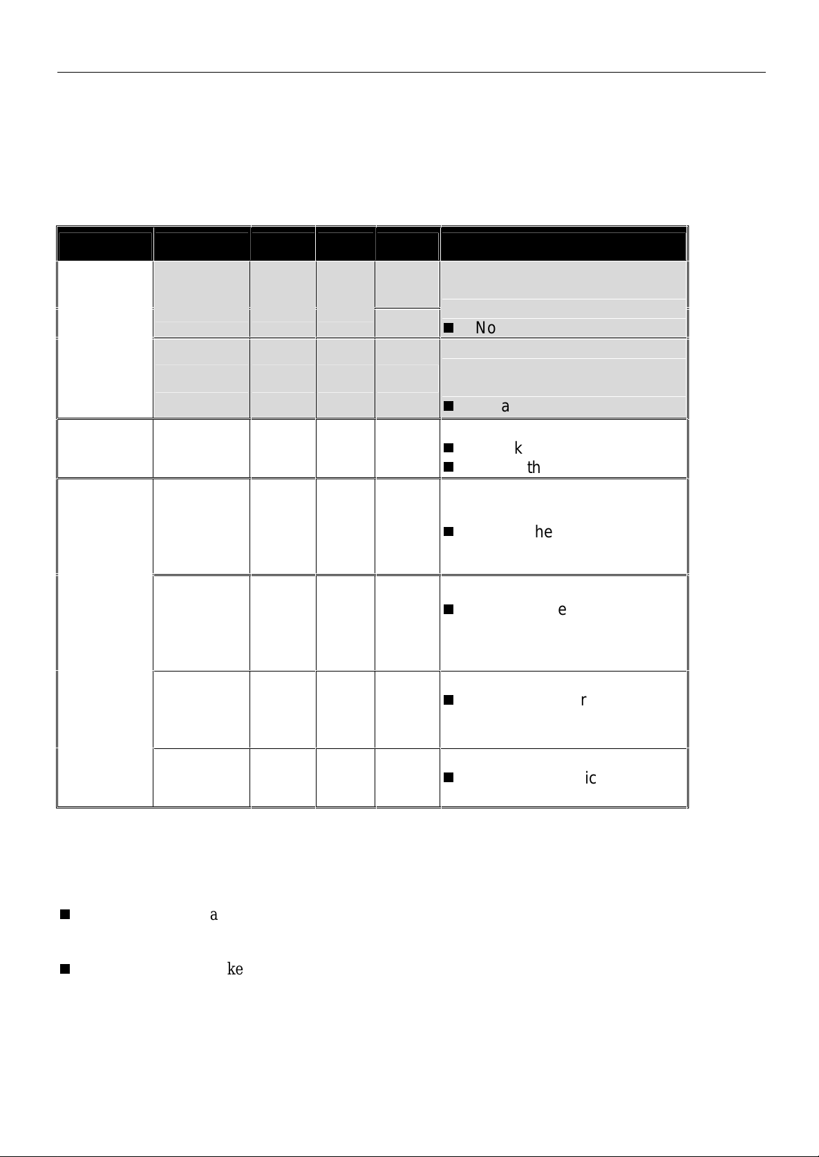
The following table provides an overview of each LED activity:
LED Definition Activity
Description
PWR Continuous Green Power enabled
AP Continuous Green The W-LAN 11 is now in service.
Off: No wireless activity
WLAN Flashing Green
Flashing: Wireless RX/TX activity
Off: No Ethernet traffic activity
LAN Flashing Green
Flashing: Wired LAN traffic
activity
Off: no station connected to the
LINK Continuous Green
Access Point
On: with one or more stations
associated to the W-LAN 11
3. Configuration / Installation
The Access Point provides a user friendly configuration utility (Access Point Manager). It is
delivered ready for use with factory default settings for use with standard W-LAN conditions.
Any configuration changes may be made using the Access Point Manager software, by web
browser administration or by console set-up using either the RS-232 console administration or
direct Ethernet Telnet connection.
Page 4
English Short Manual
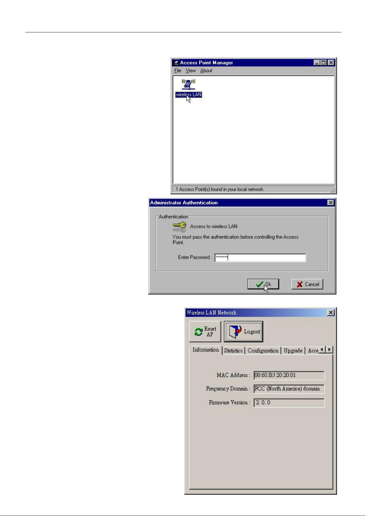
3.1. Access Point Manager Configuration Utility
The Windows based configuration
program; Access Point Manager
provides easy monitoring, checking and
changing of the Access Point parameters.
Place the enclosed CD or Floppy disk into
the computer you want to use to connect
to the AP. Start the set-up program
setup.exe from the enclosed CD or
diskette and follow the instructions given
there. When finished start the program
Access Point Manager. It will
automatically search and detect all LINDY
Access Points in your network
Double click to any Access Point
Symbol to view or change the
settings of the AP selected. The
Default Password as supplied is
“default”
After having entered the correct password the
program will display the MAC address, the
frequency domain (dependent on the
regulations of the countries where used), the
firmware version, connection statistics, the
upgrade utility page, security, access and
encryption settings, etc.
(For further details on Statistics please refer
to the extensive English reference manual)
If you want to set up a wireless LAN with more
then 1 Access Point and you are not familiar
with the basic knowledge for this kind of
WLAN, please contact your local dealer or the
LINDY support department.
At the moment we are trying to include some
additional information under the category TIPS
& MORE on our LINDY homepage
www.lindy.com.
Page 5
English Short Manual
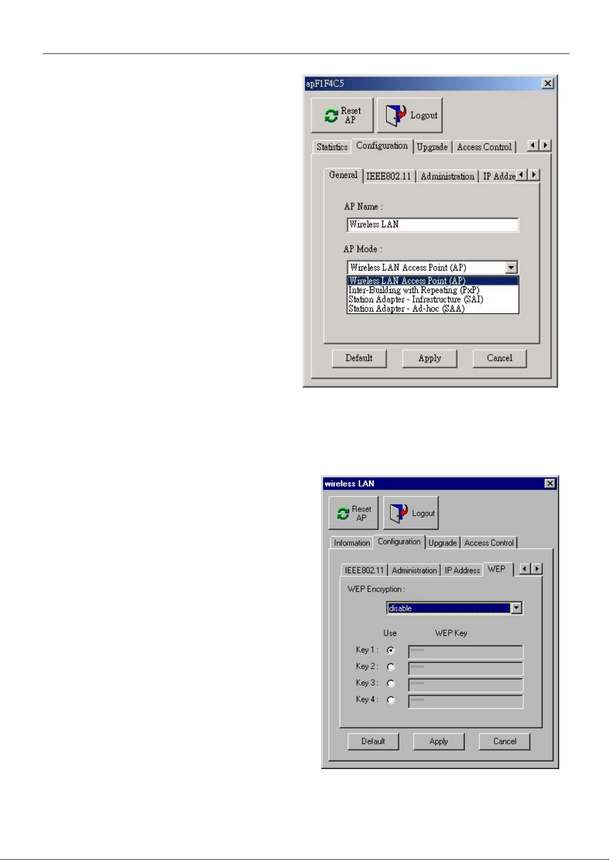
Configuration
The configuration tool provi des four different
modes of operation for the Access Point:
General
Standard AP with Roaming
Inter Building AP (Repeater, PxP)
Station Adapter – Infrastructure (SAI)
Station Adapter Ad-hoc (SAA)
(For further details please refer to the
extensive English reference manual)
IEEE802.11
,ESSID’ depicts the name of the W- LAN you
are installing. If this WLAN is to be accessed
by all possible/potential clients then use the
setting ‘Use Non-Specifi ed ESSID: nonspeci’, resp ectively the ESSID name "ANY".
If you want to secure your WLAN against
unintentional access you should give a
specified ESSID name to all of the clients
that are able to join your WLAN.
….. ID-settings, channel settings, etc.
Administration (Password)
IP Adress
IP Address, Netmask, Gateway
WEP
WEP (Wireless Encryption Protocol) is the
Encryption standard for Wireless LAN. At the
moment WEP-40 is the recent standard.
Select WEP-40 for IEEE standard comp liant
(relative) secure data transfer and make sure
every WLAN client uses the exactly same
key.
(For further details please refer to the extensive
English reference manual)
ACCESS CONTROL
Access Control allows you to create a list of
MAC Addresses for authorised PCMCIA cards.
Access to the W-LAN is possible ONLY for the
clients contained in this list.
Page 6
English Short Manual
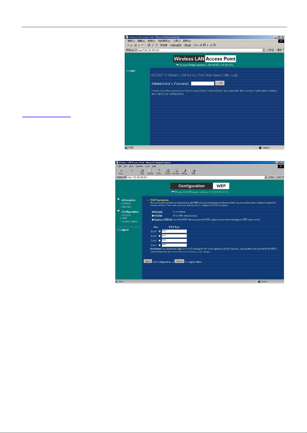
3.2. Web Management
Utility
The Access Point also provides a
web browser graphic user interface
With the preset IP-Address
http://192.168.1.1
access to the Access Point W eb
Page. Enter password to continue.
The contents of the following
pages are very similar to the
information already given in the
sections before 3.1. Access
Point Manager Configuration
Program.
(For further details please refer
to the extensive English
reference manual)
you will have
3.3. Administration via RS-232 console program or Telnet TCP/I P
The Access Point can also be accessed using the RS-232 console connection (terminal
program) using a Nullmodem cable.
Alternatively a Telnet TCP/IP can be used via the Ethernet connection.
Set up your cable connection and start the terminal program. The configuration options are
almost the same as already mentioned above in the previous chapters.
(For further details please refer to the extensive English reference manual)
Page 7
English Short Manual
4. Troubleshooting
If you have trouble using the W-LAN 11 Wireless LAN Access Point, the starting point to
troubleshoot any probl ems is by looki ng at the LED activi ty on the Access Point. The foll owing
“LED Error Table” is provided to assist you in diagnosing and solving operational problems.
PWR AP WLAN LAN LINK Description/Action
Steady
Continuous
Green
Continuous
Green
On Off Off -
Off Off Off Off Off
Off Off Off Off
Continuous
Green
Blink Green - - -
Flash
Green
Flash
Green
Green
Normal operation where
flickering indicates interface
activity.
-
n
No action required.
Normal operation that indicates
there is no LAN activity.
n
No action required.
Power failure.
n
Check the power cord.
n
Check the power supply.
Invalid loader fi rmware or the
micro-controller is dead.
n
Return the unit to the vendor
for support.
Invalid Access Point firmware.
n
Upgrade the firmware via
the utility or console mode.
Wireless LA N init ialis atio n f ailur e
Blink Green
Blink Green -
If you are still unable to solve the problem by checking the LED activity, the error may be caused by a configuration
mismatch which prevents the W-LAN 11 from establishing a wireless connection with your network. Y ou may check
the following to ensure normal operati on of the W-LAN 11.
n
WEP keys: If data encryption is activated, always remember to set WEP keys exactly the same on
the Access Point as are on t he wireless stations.
n
Access Control: Make sure t hat the MAC address of your W-LAN 11 is not included in the Access
Control ta ble of other wireless devices.
Blink
Green
- -
Blink
Green
n
Check whether the wireless
module has been properly
installed.
Ethernet initialization failure
-
n
Return the device to the
vendor for support.
Page 8

Deutsches Kurzhandbuch
1. Einleitung
Das LINDY W-LAN 11 (Wireless LAN mit 11 Mb/s) bietet eine schnelle und zuverlässige Lösung
für kabellosen Netzwerkzugriff. Es ist kompatibel zum W-LAN Standard IEEE802.11b und
802.11.
Es ist prädestiniert für den Einsatz in historischen Gebäuden, in denen kein Kabelnetzwerke
verlegt werden können, für die Anforderung mobile Einsatzorte innerhalb eines Gebäudes oder
um einen allgemeinen freien Netzwerkzugang (z.B. Internet) in einer gegebenen Umgebung
(Universität, Hotel, etc.) zu schaffen.
Verbindungen können prinzipiell als Peer-to-Peer Verbindung (Ad-Hoc) zwischen zwei
Rechnern mit W-LAN PCMCIA Karte aufgebaut werden, zwischen Access Points (Wi reless
Repeater) oder zwischen Access Point und Clients (Infrastruktur, PCMCIA Karte u.ä.). Der
LINDY Access Point beherrscht die Roaming Funktion, so dass mit mehreren Access Points ein
größeres Gebäude abgedeckt werden kann. Die Reichweite ist sehr stark von den
Gebäudegegebenheiten (Abschirmung durch Wände, Träger, etc.) abhängig und kann unter
idealen Bedingungen bis 45m reichen, im allgemeinen liegt die maximale Reichweite bei 1525m.
Im Freien kann (ohne besondere Antennen) eine Reichweite von ca. 250m erreicht werden.
Bitte beachten Sie, dass
c) ein W-LAN leicht abgehört werden kann und nur mit aktivierter Verschlüsselung
(WEP) ein gewisses Maß an Sicherheit besteht !
d) ohne aktivierte Zugangsbeschränkung und ohne aktiviertes Passwort sich jeder
Nutzer mit IEEE802.11b W-LAN Karte in das Netzt einloggen kann !
Bitte beachten Sie die Aktivierungshinweise zu di esen Themen weiter hinten im Handbuch.
Kabellose Infrastruktur
In einer kabellosen Infrastruktur fungiert das W-LAN 11 als Bridge. Der Access Point verbindet
die kabellosen Clients untereinander und agiert als Schaltzentrale für jegliche kabellose
Kommunikation. Er sorgt somit für effiziente Verbindungen, da die einzelnen Clients sich
untereinander auch außerhalb ihrer direkten Verbindungsreichweite befinden können.
2. Installation der Hardware
Bevor Sie mit der Installation beginnen, stellen Sie bitte sicher, dass Sie die folgenden Dinge
mit der Lieferung erhalten haben:
w
Den LINDY W-LAN 11 Access Point
w
Das Netzteil
w
Die Installati onsdiskette oder –CD
Sollte eines der genannten Teile fehlen, wenden Sie sich bitte an Ihren Fachhändler.
Aufstellung
Der Aufstellungsort für den Access Point sollte möglichst zentral im abzudeckenden
Funkbereich liegen, möglichst mit Abstand zu stark abschirmenden Gebäudeteilen. Der AP
kann aufgestellt oder aufgehängt werden.
Anschluss
Verbinden Sie dem MDI Port mit einem Hub bzw. den MDI-X Port mit einem Rechner bzw. einer
Workstation. Verbinden Sie das Netzteil mit Access Point und Steckdose.
Page 9

Deutsches Kurzhandbuch
Die Rückseite des W-LAN 11 Access Point :
Power: Schließen Sie hier das mitgelieferte Netzteil an.
MDI: RJ-45 Buchse zum Anschluss an Ethernet Hub mit 10BaseT oder 100BaseTX.
MDI-X RJ-45 Buchse zum Anschluss an Rechner oder Workstation, es kann nur eine der
RS-232 Konsolen Port zur Konfigurierung / Programmierung des Access Point
LEDs Zustandsanzeigen für die Ethernet Kabelverbindung
Nach korrektem Anschluss an das Ethernet muss bei eingeschalteten Rechnern/Hubs
zumindest die Link LED grün leuchten.
Die Oberseite des W-LAN 11 Access Point
Die Bedeutung der LED-Signale auf der Frontplatte des W-LAN 11 Access-Point entnehmen
Sie der folgenden Tabelle:
POWER MDI MDI-X RS-232
100M TX
Link
RX
OR
beiden MDI / MDI-X Buchsen verwendet werden!
LED-Bezeichnung Aktivität Bedeutung
PWR Dauerhaft grün Spannungsversorgung korrekt
AP Dauerhaft grün Access Point für Netzwerkdienste verfügbar
aus: keine RX/TX-Aktivität über Funksignal
WLAN Grün flackernd
blinkt: RX/TX-Aktivität Wirel ess
aus: keine RX/TX-Aktivität über Ethernet
LAN Grün flackernd
blinkt: Ethernet-Kabelseitige RX/TX-Aktivität
aus: keine Station mit dem Access Point verbunden
LINK Dauerhaft grün
an: verbunden mit einer oder mehreren Stationen
verbunden
3. Inbetriebnahme / Konfiguration
Der Access Point kommt betriebsfertig mit allgemein vordefinierten Einstellungen.
Diese können für die individuellen Belange umkonfiguriert werden unter Verwendung eines
mitgelieferten Konfigurationsprogramms (Access Point Manager), durch Anschluss einer
Konsole und ein Konsolen-Utility oder direkt über das Netz (TCP/IP, Telnet Verbindung).
Page 10

Deutsches Kurzhandbuch
3.1. Access Point Manager Konfigurationsprogramm
Das Windows basierte Konfigurationsprogramm Access Point Manager
erlaubt die einfache Konfigurierung aller
Parameter des Access Points.
Legen Sie die CD oder Floppy in den
Rechner mit dem Sie den Access Point
konfigurieren wollen. Starten Sie das
Setup-Programm setup.exe von der
mitgelieferten Diskette oder CD und
folgen Sie den Anweisungen. Nach
Abschluss der Installation starten Sie das
Programm Access Point Manager. Das
Programm wird alle LINDY Access Points
im Netzwerk suchen und anzeigen.
Doppelklicken Sie auf ein Access
Point Symbol um seine
Einstellungen zu sehen bzw. zu
ändern. Das Passwort im
Lieferzustand ist „default“.
Nach Eingabe des korrekten
Passwortes sehen Sie im
Konfigurationsprogramm
die Einstellungen für MAC
Adresse, Frequenz Domain (abhängig vom
Einsatzort), Firmware Stand,
Verbindungsstatistiken,
Konfigurationseinstellungen, Upgrade-Utility,
Zugriffs-Sicherheits-Einstellungen, etc.
Sollten Sie ein Wireless LAN mit mehreren
Access Points aufbauen wollen und nicht
über das spezielle Basiswissen für solche
Funknetze verfügen, so wenden Sie sich bitte
an Ihren Fachhändler oder an den LINDY
Support. Wir bemühen uns, weitere
Informationen auf der LINDY Homepage
unter der Rubrik TIPS zur Verfügung zu
stellen.
Weitergehende Erläuterungen über
Statistics entnehmen Sie bitte dem
ausführlichen Englischen Handbuch.
Page 11

Deutsches Kurzhandbuch
Konfiguration
Das Konfigurationstool ermöglicht
verschiedene Betriebarten für den Access
Point:
General
Standard AP mit Roaming
Inter Building AP (Repeater, PxP)
Station Adapter –Infrastructure (SAI)
Station Adapter Ad-hoc (SAA)
(Details siehe ausführliches Englisches
Handbuch)
IEEE802.11
‚ESSID’ bezeichnet den Namen des von
Ihnen einzurichtenden Netzwerkes. Soll das
WLAN für alle potentiellen Teilnehmer völlig
offen sein, so sollten Sie die Einstellung ‚Use
Non-Specified ESSID: non-speci’, bzw. den
ESSID Namen "ANY" wählen. Wenn Sie ihr
Netz gegen ungewollten Zugang absichern
wollen, so vergeben Sie einen geeigneten bei
allen Teilnehmern gleichen ESSID Namen!
Kanaleinstellungen, etc.: Wählen Sie einen geeigneten Kanal aus der Liste. (Details siehe
ausführliches Englisches Handbuch)
Administration (Passwort)
IP Adress
IP Adresse, Netzmaske, Gateway
WEP
WEP (Wireless Encryption Protocol) ist der
Verschlüsselungsstandard für Wireless LAN. Zur
Zeit bildet WEP-40 den aktuell festgelegten
Standard.
Wählen Sie WEP-40 für zum IEEE Standard
kompatiblen (relativ) sicheren Datentransfer
und stellen Sie sicher, dass alle Teilnehmer
des WLAN den exakt gleichen KEY
verwenden.
(Details siehe ausführliches Englisches
Handbuch)
ACCESS CONTROL
Unter Access Control kann eine Liste mit MAC
Adressen von zugelassenen PCMCIA Karten
erstellt werden, anderen wird der Zugriff auf das
W- LAN nicht ermöglicht.
Page 12

Deutsches Kurzhandbuch
3.2. Web Management
Utility
Der Access Point stellt ebenfall s
eine Browser Seite als graphische
Konfigurationsoberfläche zur
Verfügung.
Nach Eingabe der voreingestellten
IP-Adresse http://192.168.1.1
(Lieferzustand) sehen Sie die
Access Point Web-Seite mit der
Aufforderung zur Eingabe des
Passwortes.
Die Inhalte der Folgeseiten sind
weitestgehend identisch mit den
oben unter 3.1. Access Point
Manager
Konfigurationsprogramm
genannten.
(Details siehe ausführliches
Englisches Handbuch)
3.3. Administration über das Konsolenprogramm bzw. RS-232
Der Access Point kann ebenso über eine RS-232Konsolenverbindung (Terminalprogramm)
administriert werden. Dazu ist serielles Nullmodemkabel (RS-232) zu verwenden.
Alternativ kann eine Telnet TCP/IP Verbindung über das Netzwerk verwendet werden.
Stellen Sie dazu die Kabelverbindung her und starten Sie das Terminalprogramm. Die
Konfigurationsoptionen entsprechen weitestgehend den oben unter 3.1. Access Point Manager
Konfigurationsprogramm genannten.
(Details siehe ausführliches Englisches Handbuch)
Page 13

Deutsches Kurzhandbuch
4. Fehlersuche
Bei Problemen mit dem W-LAN 11 Access Point sollte der Fehler systematisch ausgehend von
den LED Anzeigen auf dem Access Point analysiert werden.
Die folgende Tabelle gibt Hinweise bezugnehmend auf den Zustand der LEDs:
PWR AP WLAN LAN LINK Beschreibung/Massnahme
Dauerhaft
Leuchtet
dauerhaft
grün
Aus Aus Aus Aus Aus
Leuchtet
dauerhaft
grün
grün
An Aus Aus -
Aus Aus Aus Aus
Blinkt grün - - -
Flackert
grün
Flackert
grün
grün
-
Normalbetrieb, das Flackern zeigt
Datentransfer an.
n
Alles OK.
Normalzustand, kein Datentransfer, Netz
ist inaktiv
n
Alles OK.
Spannungsversorgungsfehler.
n
Steckernetzteil und Spannung prüfen
n
Anschlussstecker am Access Point
prüfen.
Inkorrekte Firmware oder Defekt des
Access Point.
n
Rückgabe des Gerätes an den
Lieferanten/Hersteller.
Ungültige Access Point Firmware.
n
Upgrade der Firmware über Access
Point Manager Software oder
Konsolenbetrieb oder Web Page.
Wireless LAN Initialisierungsfehler
Blinkt grün
Blinkt grün -
Sollt en die genannten Maßnahmen nicht zur B ehebung des Problems führen, kann der Fehler möglicher weise auf
eine Inkompatibilität zwischen verschiedenen Konfigurat ionseinstell ungen her r ühren. Überprüfen Sie bitte noc h
folgendes um den Normalbetrieb zu erreichen:
n
WEP Sicherheitseinstellungen: Fa lls Dat en vers chlüsselung akt iviert ist bede nken Sie bitt e, d ass die
WEP keys auf allen Clients und Access Points ABSOLUT identisch sein müssen!
n
Access Control : Falls aktiviert, st ellen Sie sicher, dass die MAC Adressen aller Clients in der Access
Contr ol Liste des ( der) Access Point(s) eingetr ag en sind.
Blinkt
grün
- -
Blinkt
grün
-
n
Prüfen Sie ob die PCMCIA Karte
korrekt installiert ist. Öffnen Sie die
Klappe auf der Unterseite des AP
Ethernet Initialisierungsfehler.
n
Rückgabe des Gerätes an den
Lieferanten/Hersteller.
Page 14

Manuel condensé en français
1. Introduction
Le LINDY W-LAN 11 (Réseau sans fil à 11 Mb/s) offre une soluti on rapide à mettre en place et
efficace pour un réseau professionnel. Ce produit est conforme aux standards
IEEE802.11b et 802.11. et convient particulièrement dans les anciens bâtiments où il est
impossible d’installer un câblage réseau et d’y apporter des modifications par la suite, et dans
les universités, h ôpitaux, pour un accès réseau dédié (Internet).
Les connexions sont établies par paire (ex. portable avec carte W-LAN PCMCIA), entre les
points d’accès (Hub sans fil) ou entre le point d’accès et les postes clients (carte PCMCIA ou
similaire). Le point d’accès LINDY possède une fonction de balayage, de ce fait même les plus
grands bâtiments sont couverts par la portée du réseau sans fil.
La transmission maximum entre deux points dépend fortement de l’environnement local, de la
structure du bâtiment, de l’isolation des murs et de la structure métallique des murs et des
planchers du bâtiment. Sous des conditions idéales, la transmission possède une portée de
45m, dans la plupart des cas la portée se situe entre 15 et 25m. Il est possible d’avoir une
portée maximale théorique de 250m dans un environnement libre de toutes perturbations.
Remarques:
e) Un réseau sans fil peut être facilement accédé par des personnes non autorisées.
La seule protection possible est si vous bénéficiez de protections en cryptage!
f) Sans contrôle d’accès activé, toute personne possédant le matériel compatible
avec le réseau sans fil IEEE802.11 pourra accéder au réseau!
Veuillez vous référer à la description détaillée indiquée dans le manuel ultéri eurement.
Infrastructure sans fil Wireless
Dans une structure sans fil, le W-LAN 11 joue le rôle de pont. Le point d’accès connecte tous
les clients sans fil ensemble et centralise toutes les communications sans fil.
Ceci peut améliorer l’efficacité des communications car les points wireless ne doivent pas être
l’un à coté de l’autre pour fonctionner.
2. Installation matérielle
Avant de commencer, soyez certain que les éléments suivants figurent dans l’emballage:
w
Le point d’accès LINDY W-LAN 11
w
L’adaptateur d’alimentation
w
Le disque d’install a tion ou CD
Si quelque chose venait à manquer, contactez votre fournisseur.
Placement du point d’accès
Avant l’installation, choisissez le meilleur emplacement pour votre point d’accès.
L’emplacement doit être de préférence central, autour des points de communications sans fil
du réseau W-LAN. Il doit être placé à distance d’éléments métalliques perturbants du bâtiment.
Le point d’accès peut être placé à pl at ou bien vissé sur un mur.
Connexions
Connectez le port MDI du point d’accès à votre Hub Ethernet ou connectez le port MDI-X à un
ordinateur ou une station de travail utilisant un câble droit STP/UTP. Connectez l’adaptateur
d’alimentation au point d’accès puis au secteur.
Page 15

Manuel condensé en français
Vue arrière de votre point d’accès W-LAN 11:
Power: Connectez l’adaptateur d’alimentation ici.
MDI: Connecteur RJ-45 pour Hub Ethernet 10BaseT ou 100BaseTX.
MDI-X Connecteur RJ-45 pour connecter un ordinateur à une station, il n’est possible
RS-232 Port pour configurer et programmer le point d’accès
LED’s Affichage du statut pour le réseau sans fil
Après une installation correcte de toutes les connexions au réseau sans fil, la LED Link doit
toujours être allumée lors de la mise en route des stations clients et du hub.
Le panneau frontal du point d’accès W-LAN 11
POWER MDI MDI-X RS-232
100M TX
Link
RX
OR
d’utiliser que les connecteurs marqués MDI / MDI-X!
Le tableau suivant indi que les activités des LED suivantes:
Définition LED Activité
Description
PWR Vert continu Alimentation activée
AP Vert continu Le point d’accès est en service.
Eteint: pas d’activité sans fil
WLAN Vert clignotant
Clignotant: activité sans fil
RX/TX
Eteint: pas de trafic Ethernet
LAN Vert clignotant
Clignotant: activité du réseau
sans fil
Eteint: pas de station connectée
LINK Vert continu
au point d’accès
Allumé: une ou plusieurs stations
connectées au point d’accès
3. Configuration / Installation
Le point d’accès est fourni avec un utilitaire de configuration (Access Point Manager). Il est
livré prêt à l’emploi avec les réglages d’usine par défaut. Les modifications de la configuration
sont faites en utilisant le programme Access Point Manager software, par navigateur web ou
par une console RS-232 ou une connexion directe Ethernet Telnet.
Page 16

Manuel condensé en français
3.1. Utilitaire de configuration Access Point Manager
Le programme de configuration Windows,
Access Point Manager vous fournit une
consultation facile, une vérification et la
modification des paramètres du
point d’accès.
Insérez le CD ou la disquette dans le
lecteur de l’ordinateur que vous souhaitez
connecter. Lancez le programme
d’installation setup.exe de la disquette ou
du CD-ROM fourni et suivez les
instructions suivantes. L’installation
terminée, démarrez le programme
Access Point Manager. Il va
automatiquement rechercher et détecter
tous les points d’accès LINDY sur votre
réseau.
Double-cliquez sur n’importe quel
symbole de point d’accès pour voir
ou modifier les paramètres de ce
dernier. Le mot de passe par
défaut installé est “default”.
Après avoir entré le bon mot de passe, le
programme va afficher l’adresse MAC,
la région de fréquence concernée (dépend
des pays où l’appareil est utilisé), la version
du BIOS, les statistiques de connexions, la
page de mise à jour, les accès sécurisés,
les paramètres de cryptage, etc.
(Pour plus de détails concernant les Statistics
veuillez vous référer à l’extension en langue
anglaise à ce manuel)
Si vous souhaitez installer un réseau sans fil
avec plus d’un point d’accès et si vous
débutez dans ce milieu, veuillez contacter
votre revendeur local ou le service technique
de LINDY.
Page 17

Manuel condensé en français
Configuration
L’utilitaire de configuration fournit quatres
différents modes d’utilisation pour le point
d’accès:
General
Standard AP with Roaming
Inter Building AP (Repeater, PxP)
Station Adapter – Infrastructure (SAI)
Station Adapter Ad-hoc (SAA)
(Pour plus de détails, veuillez vous référer à
l’extension anglaise du manuel)
IEEE802.11
‚ESSID’ est différent du réseau W-LAN que
vous installez. Si ce réseau sans fil doit être
accessible par tous les clients potentiels, i l est
suggéré d'utiliser le paramètre‚Use Non-
Specified ESSID: non-speci ’, respectivement le
nom ESSID sur "ANY". Si vous souhaitez
protéger l'accès à votre réseau sans fil contre
tout accès non autorisé, il est conseillé de donner un nom ESSID spécifiques à tous vos clients
étants capables de se connecter au réseau WLAN.
Channel settings, etc.
Administration (Mot de passe)
IP Adress
Adresse IP, masque de sous-réseau, passerelle
WEP
WEP (Wireless Encryption Protocol) est le
standard de cryptage pour le réseau sans fil.
Le standard WEP-40 est le standard actuel.
Sélectionnez WEP-40 pour les transferts de
données sécurisés IEEE et soyez certai n que
tous les clients du réseau sans fil WLAN
utilisent la même clé.
(Pour plus de détails, consultez l’extension
anglaise de ce manuel)
Contrôle d’accès
Le contrôle d’accès vous permet de créer une liste d’adresses MAC pour les cartes PCMCIA
autorisées. L’accès au réseau sans fil est uniquement autorisé pour les clients enregistrés dans
cette liste.
Page 18

Manuel condensé en français
3.2. Utilitaire Web
Le point d’accès fournit une
interface web pour l’utilisateur
Avec l’adresse IP préréglée
http://192.168.1.1 vous aurez
accès à la page web du point
d’accès. Entrez le mot de passe
pour continuer.
Le contenu de la page suivante
est très similaire aux
informations indiquées au
paragraphe précédent 3.1.
Configuration du point d’accès.
(Pour plus de détails, consultez
l’extension anglaise de ce
manuel)
3.3. Administration par une console RS-232 ou Telnet TCP/IP
Le point d’accès peut être contrôlé à partir d’une console RS-232 (terminal) à l’aide
d’un câble Nullmodem.
Une connexion alternative Telnet TCP/IP peut également être utilisée avec une connexion
Ethernet.
Installez votre câblage et lancez le programme du term inal. Les options de configuration restent
les mêmes que citées ci-dessus.
(Pour plus de détails, consultez l’extension anglaise de ce manuel)
Page 19

Manuel condensé en français
4. Problèmes techniques
Si vous rencontrez des problèmes durant l’installati on du point d’accès W -LAN 11, la première
chose à fai re pour résoudre le problème est de vérifier l ’activité des LEDs sur le point d’accès.
Le tableau des erreurs LED suivant vous permettra certainement de résoudre le problème:
PWR AP WLAN LAN LINK Description/Action
Vert Continu
Vert Continu
Allumé Eteint Eteint -
Eteint Eteint Eteint Eteint Eteint
Eteint Eteint Eteint Eteint
Vert Continu
Vert Clignot. - - -
Vert
Clignot.
Vert
Cligno.
Vert
Fixe
-
Fonctionnement normal
indiquant une activité sur
l’interface.
n
Pas d’action nécessaire.
Fonctionnement normal
indiquant aucune activité réseau.
n
Pas d’action nécessaire.
Problème d’alimentation.
n
Vérifiez le cordon
d’alimentation.
n
Vérifiez l’alimentation.
BIOS invalide ou microcontrôleur
défectueux.
n
Retournez l’élément à votre
fournisseur pour support.
BIOS du point d’accès invalide.
n
Mettre à jour le BIOS par
l’utilitaire fourni ou par le
mode console.
Initialisation du réseau sans fil
Vert Clignot.
Vert Clignot. -
Si vous ne parvenez toujours pas à résoudre le problème rencontré en vérif iant les LED d’activité, l’erreur peut
provenir d’un problème de configuration W- LA N 11 empêchant l e pr oduit d’établir une c onnexion sans fi l sur vot r e
réseau. Il est conseillé dans ce cas de vérifier les points suivants.
n
Touches WEP: Si le cryptage de données est activé, vérifiez bien que le réglage des touches WEP
soit exactement le même s ur le po int d’accès que sur les stations connectées.
n
Contrôle d ’accès: Soyez sûr que l’adresse MAC du W-LAN 11 ne soit pas incluse dans la table de
contrôle d’accès des périphériques sans fil.
Vert
Clignot.
- -
Vert
Cligno.
n
Vérifiez que le module de
réseau sans fil a été
correctement installé.
Problème d’initialisation du
réseau Ethernet
-
n
Retournez le produit à votre
fournisseur.
Page 20

Estratto del Manuale in Italiano
1. Introduzione
La LINDY W -LAN 11 (Wi reless LAN con 11 Mb/s) offre una soluzione rapida ed affidabi le per
trasmissioni in cablaggi di rete professionali senza fili. E’ compatibile con gli standard
IEEE802.11b e 802.11. ed è ideale per l’util izzo i n edi fi ci stori ci dove non vi è una struttura che
non può essere cablata, per la richiesta di accesso alla rete all’interno di un edificio, e per libero
ed aperto accesso alla rete (Internet) p.es. nelle università, hotel ecc.
Le connessioni possono essere stabilite come punto-a-punto (p.es. notebook con schede WLAN PCMCIA), tra punti di accesso (ripeti tori wireless) o tra punti di accesso e client (scheda
PCMCIA o similari). La LINDY Access Point offre una funzione di roaming cosicché anche
edifici di grandi dimensioni possono essere coperti dalla rete LAN senza fili.
La massima distanza di trasmissione tra due punti dipende dall’ambiente locale, dalla
costruzione dell’edificio e dalla disposizione dei muri dai soffitti e dal tipo di metalliche
costituisce le parti dell’edificio. Sotto una condizione ideale la trasmissione copre un raggio fino
a 45m, nella maggior parte dei casi la distanza è tra 15 e 25m. In un ambiente libero senza
riflessioni una distanza di 250m può essere raggiunta.
Prego notare:
g) Una rete LAN senza fili può essere facilmente accessibile da persone estranee non
autorizzate. Solo quando il criptaggio è stato attivato vi è una sicurezza contro
questo!
h) Senza aver attivato il Controllo di Accesso e senza nessuna password ogni utente
con una rete senza fili LAN IEEE802.11 compatibile può accedere all’interno della
stessa !
Prego fare riferimento alla descrizione dettagliata più avanti in questo manuale.
Infrastruttura Rete senza fili
In una infrastruttura di rete senza fili, la W-LAN 11 agisce come un ponte. Il punto di Accesso
connette la rete senza fili ai client insieme ed agisce un punto centrale per tutte le
comunicazioni senza fili. Questo aumenterebbe l’efficienza delle comunicazioni poiché i
dispositivi wirel ess non necessitano di essere posti al l’i nterno di uno schema in serie uno dopo
l’altro.
2. Installazione Hardware
Prima di iniziare assicurarsi che I seguenti articoli siano inclusi:
w
La LINDY W-LAN 11 Access Point
w
L’alimentatore
w
Il disco di Installazione o il CD
Se qualcosa manca o è danneggiata, prego contattare il Suo rivenditore.
Posizionamento del Punto di Accesso
Prima dell’installazione determinare la posizione migliore per l’AP. La posizione dovrebbe
essere centrale, relativamente all’area di copertura del l’W-LAN. Dovrebbe essere posizionato
ad una certa distanza dalle pareti dell’edificio. L’AP può essere messo anche su di una
superficie piana o montato verticalmente sul muro.
Connessioni
Connettere la porta MDI dell’AP all’hub Ethernet o connettere la porta MDI-X al computer o alla
stazione di lavoro utilizzando un cavo dritto S TP/UTP. Connett ere l’aliment a t o re all’AP e c o lleg ar lo alla
corrente.
Page 21

Estratto del Manuale in Italiano
Visione posteriore del vostro W-LAN 11 Access Point:
Power: Collegare qui l’alimentatore.
MDI: Connettore RJ-45 per Hub Ethernet con 10BaseT o 100BaseTX.
MDI-X Connettore RJ-45 per collegare un computer o stazione di lavoro, potete
RS-232 Porta console per configurare e programmare l’Access Point
LED Display dello stato del cablaggio Ethernet
Dopo aver correttamente connesso tutto il cablaggio del la LAN dovrebbe apparire sul LED dei
collegamenti la luce verde quando gli hub o le stazioni di lavoro/computer sono connesse.
La parte superiore del panello dell’W-LAN 11 Access Point
POWER MDI MDI-X RS-232
100M TX
RX
Link
OR
solamente utilizzare uno dei connettori indicanti MDI / MDI-X!
La seguente tabella indica una visione complessiva di ciascun LED di attività:
Definizione LED Attività
Descrizione
PWR Verde Costante Alimentazione attiva
AP Verde Costante Il W-LAN 11 è ora in attività
Off: Wireless inattiva
WLAN Verde Lampeggiante
Lampeggiante: Wireless RX/TX
attiva
Off: Nessun segnale di attività
LAN Verde Lampeggiante
Ethernet
Lampeggiante: Trasmissione
attiva nel cablaggio LAN
Off: nessuna stazione è connessa
LINK Verde Costante
all’Access Point
On: con uno o più stazioni
collegate al W-LAN 11
3. Configurazione / Installazione
L’Access Point è provvisto di una utilità per una facile configurazione da parte dell’utente
(Access Point Manager). E’ fornito pronto per l’utilizzo con una configurazione di base per
l’uso in normali condizioni con una W-LAN. Qualsiasi cambiamento della configurazione può
essere effettuato mediante l’utilizzo del Software Access Point Manager, dall’amministratore
del sistema web browser o utilizzando la console di amministrazione tramite RS-232 o
direttamente via connessione Ethernet Telnet.
Page 22

Estratto del Manuale in Italiano
3.1. Configurazione delle Utility da Access Point Manager
Il programma della configurazione di base
di Windows; Access Point Manager
permette un facile monitoraggio, controllo
e cambio dei parametri dell’Access Point.
Inserire nel computer che desiderate
utilizzare e collegare all’ AP, il CD o il
Floppy disk che è compreso nella
fornitura. Avviare il programma di
installazione setup.exe dal CD o dal
dischetto e seguire le istruzioni
successive. Successivamente avviare il
programma Access Point Manager.
Automaticam ente cercherà e r ile v e rà tutti i
LINDY Access Points nella rete.
Doppio click su ogni simbolo
Access Point per visuali zzare o
cambiare il settaggio dell’AP
selezionato. La Password di base è
“default”
Dopo aver inserito la password
corretta il programma mostrerà
l’indirizzo MAC, la frequenza di
dominio (dipendente a seconda
della zona dove è utilizzata), la versione del
firmware, le statistiche delle connessioni, la
pagina dell’aggiornamento delle utilità,
sicurezza, i parametri di accesso e criptaggio,
ecc.
(Per maggiori dettagli sulle Statistiche prego
fare riferimento all e estensioni del manuale in
Inglese).
Se desiderate settare una rete LAN senza fili
con più di un Access Point e non avete
familiarità con l’installazione di questo tipo di
WLAN, prego contattare il fornitore locale
oppure il supporto tecnico LINDY.
Al momento stiamo provvedendo ad
aggiungere ulteriori informazioni sul nostro
sito Internet alla sezione TIPS & MORE sulla
homepage LINDY www.lindy.com.
Page 23

Estratto del Manuale in Italiano
Configurazione
I metodi di configurazione prevedono Quattro
differenti modi di operare per l’Access Point:
Generale
Standard AP con Roaming
AP Edifici Sotterranei (Ripetitore, PxP)
Adattatore Stazione – Infrastrutture (SAI)
Adattatore Stazione Ad-hoc (SAA)
(Per ulteriori dettagli prego fare riferimento
alle estensioni del manuale in Inglese)
IEEE802.11
‚ESSID’ definisce i l nome della W-LAN
installata. Se questa WLAN sarà accessibile
per tutti i potenziali/client si dovrebbe
utilizzare il settaggio, Uso Non-Specificato
ESSID: non-speci', rispettivamente il nome
dell a ESSID "ALCUNO". Se si vuole essere
certi degli accessi alla WLAN, si dovrebbe
specificare il nome ESSID a tutti i clien t che
potranno connettersi alla WLAN.
Settaggio-ID, settaggio canali, ecc.
Amministrazione (Password)
Indirizzi IP
Indirizzi IP, Netmask, Gateway
WEP
WEP (Wireless Encryption Protocol) è il
Criptaggio standard per LAN senza fili. Al
momento WEP-40 è lo standard attuale.
Selezionare WEP-40 per lo standard
compatibile IEEE (relativo) in merito alla
sicurezza del trasferimento dati e assicurarsi
che ogni client WLAN utilizzi esattamente la
stessa chiave.
(Per ulteriori dettagli prego fare riferimento alle
estensioni del manuale in Inglese)
ACCESSO CONTROL
L’ Access Control permette di creare una lista di
indirizzi MAC per autorizzare altre schede
PCMCIA. Accedere alla W-LAN è possible
SOLO per I client presenti in questa lista.
Page 24

Technical Data / CE Declaration of Conformity
3.2. Utilità Web
Management
L’Access Point dispone anche di
un’ interfaccia grafica web browser
Con gli Indirizzi-IP iniziali
http://192.168.1.1
accesso alla pagina Web
dell’Access Point. Inserire la
password per continuare.
I contenuti delle seguenti
pagine sono molto similari alle
informazioni fornite nelle pagine
precedenti nella sezione 3.1.
Configurazione Programma
Access Point Manager.
(Per ulteriori dettagli prego fare
riferimento alle estensioni del
manuale in Inglese)
potete avere
3.3. Amministrazione tramite consol e RS -232 o Telnet TCP/IP
L’accesso all’Access Point può anche avvenire tramite il collegamento di una console RS-232
(programmazione terminale) utilizzando un cavo Nullmodem.
Diversamente può essere usata una connessione Telnet TCP/IP di tipo Ethernet.
Installare il cavo ed avviare il programma del terminale. Le opzioni di configurazione sono molto
simili a quelli descritte nei precedenti capitoli.
(Per ulteriori dettagli prego fare riferimento alle estensioni del manuale in Ingl ese).
Page 25

Technical Data / CE Declaration of Conformity
4. Soluzione ai Problemi
Se avete difficoltà ad utilizzare il W-LAN 11 Wireless LAN Access Point, il punto di partenza per
ogni problema è guardare I LED di attività sull’ Access Point. La seguente “Tabella Errori LED”
è prevista per assistervi nella diagnostica e nelle operazioni per la ri soluzione dei problemi.
PWR AP WLAN LAN LINK Descrizione/Azione
Fisso
Verde
Costante
Verde
Flash
Verde
Flash
Verde
Verde
-
Costante
On Off Off -
Off Off Off Off Off
Off Off Off Off
Verde
Costante
Intermitt.
Verde
- - -
Normale operazione dove il
lampeggio indica attivi tà.
n
Nessuna azione richiesta.
Normale operazione indicante
che non c’è attività nella LAN.
n
Nessuna azione richiesta.
Alimentazione mancante.
n
Verificare il cavo aliment.
n
Verificare l’alimentatore.
Invalidità del caricamento del
firmware o guasto al microcontroller
n
Restituire al fornitore per la
sostituzione.
Invalidità del firmware
dell’Access Point.
n
Aggiornare il firmware
tramite le utilità o la console.
Inizializzazione della Wirel e ss
Intermitt.
Verde
Intermitt.
Verde
- -
LAN fallita
n
Verificare che il modulo
wireless sia stato
correttamente installato.
Intermitt.
Verde
-
Intermitt.
Verde
Inizializzazione Ethernet fallita
-
n
Restituire il prodotto al
fornitore per la sostituzi one.
Se non è stato possibile risolvere il probl ema controllando I LED di attività, l’errore può essere causato da un
conflitto della configurazione proveniente dal W-LAN 1 1 nello stabilire una connessione senza fili con la V o s tra re te .
Potete verificare quanto segue per assicur ar si delle norm ali operazi oni del W -LAN 11.
n
Tasti WEP: Se il criptaggio dei dati è attivo, ricordarsi di settare sempre i tasti WEP nello stesso
mo do di quelli d ell’Access Point come sulle altre stazioni.
n
Controllo Accesso: Assicurarsi che l’indirizzo MAC del Vostro W-LAN11 non sia incluso
nell’Access Control degli altri dispositivi wireless.
Page 26

Technical Data / CE Declaration of Conformity
EG-Konformitätserklärung gemäß dem Gesetz über Funkanlagen
und Telekommunikationsendeinric htungen (FTEG)
und der Richtlinie 1999/5/EG (R&TTE)
EC Declaration of Conformity in accordance with the Radio and
Telecommunications Terminal Equipment Act (FTEG)
Wir erklären, dass das folgend bezeichnete Produkt
We declare that the following designated product
bei bestimmungsgemäßer Verwendung den grundlegenden Anforderungen des § 3
und den übrigen einschlägigen Bestimmungen des FTEG (Artikel 3 der R&TTE)
entspricht.
complies with the e ssential require me nts of §3 and the other relevant provisions of the FTEG (Article 3
of the R&TTE
Directi ve), when used for its intended pur pose.
Das Produkt beinhaltet das Funkm odul LINDY PCMCIA Card Art. Nr. 52000
The product contains the radio frequency module LINDY PCMCIA Card Art. No. 52000.
Das Produkt entspricht den Anforderungen der Richtlinien 1999/5/EG (R&TTE),
73/23/EG (Niederspannungsrichtlinie) und 93/68/EG. Die Bewertung der Konformität
des Produktes bezüglich der Anforderungen der Elektrischen Sicherheit erfolgte
basierend auf folgendem Standard:
The product complies with the requirements of R&TTE Directive 1999/5/EEC, the European
Community Directives 73/23/EEC and 93/68/EEC. Assessment of compliance of the product with the
requirements relating to Electrical Safety was ba sed on the following s tandard:
Das Produkt entspricht Anforderungen den Richtlinie 1999/5/EG (R&TTE) und
89/336/EG (EMV, Elektromagnetische Verträglichkeit). Die Bewertung der
Konformität des Produktes bezüglich der Anforderungen der Elektromagnetischen
Verträglichkeit erfolgte basierend auf folgenden Standards:
The product complies with the essential protection requirements of R&TTE Directive 1999/5/EEC and
of the Council Directive 89/336/EEC. Assessment of compliance of the product with the requirements
relating to Electromagnetic Compatibilty was based on the following standard:
and Directive 1999/5/EC (R&TTE Directive)
LINDY WLAN Access Point, Art.Nr.: 52020
(Funkanlage Geräteklasse 2 / Radio Equipme nt, Equipme nt Class 2 )
EN 60950 : 1997
ETS 300 826 (+A1):1997, EN55022:1997,
EN50081-1:1992, EN50082-1:1992
Das Produkt entspricht den grundlegenden Anforderungen der Richtlinie 1999/5/EG
(R&TTE) bezüglich der Maßnahmen zur effizienten Nutzung des
Funkfrequenzspektrums. Die Bewertung der Konformität des Produktes (Klasse 2.7)
bezüglich der Anforderungen der Funkfrequenzenbelange (Maßnahmen zur
effektiven Nutzung des Funkspektrums) erfolgte basierend dem Anhang IV der
Richtlinie 1999/5/EG und auf folgendem Standard:
The product complies with the essential protection requirements of R&TTE Directive 1999/5/EEC on
the approximation of the laws of the Member States relating to Radio Spectrum M atters. Assessm ent
of compliance of the product (class 2.7) with the requirements relating to Radio Spectrum Matters was
based on Annex IV of the Directive 1999/5/EC and the following standard:
ETS 300 328 : 1997
Das genannte Produkt darf nur in folgenden Mitgliedsländern der EG vertrieben
und in Betrieb genommen werden:
Deutschland, Italien, Östreich, England, Belgien, Niederlande, Luxemburg.
The product may only be sold and brought into use in the following memebr countries of the
EC:
Germany, Italy, Austria, Great Britain, Belgium, Netherlands, Luxemburg.
In folgenden Ländern der EG darf das Produkt nicht in Betrieb genommen
werden:
In the following member countries of the EC the product may NOT be brought into use :
Frankreich / France , Spanien / Spain / Espagne.
Diese Einschränkungen beruhen maßgeblich auf den vom Gerät verwendeten
Funkfrequenzen, die bei Ausfertigung dieser Konformitätserklärung NICHT
europaweit einheitlich harmonisiert und nutzbar waren/sind.
These limitations are due to the radio frequency range used by the unit that are not yet
harmonized throughout all countries of the EC.
Einschränkungen / Limitations
Diese Erklärung wird verantwortlich für
LINDY Elektronik GmbH
Markircher Straße 20
68229 Mannheim
Germany
abgegeben durch
Jürgen Lindenberg
Geschäftsführer
Mannheim, 19. FEB 2001
............................................
EG-Konformitätserklärung gemäß dem Gesetz über Funkanlagen
und Telekommunikationsendeinric htungen (FTEG)
und der Richtlinie 1999/5/EG (R&TTE)
EC Declaration of Conformity in accordance with the Radio and
Telecommunications Terminal Equipment Act (FTEG)
Wir erklären, dass das folgend bezeichnete Produkt
We declare that the following designated product
bei bestimmungsgemäßer Verwendung den grundlegenden Anforderungen des § 3
und den übrigen einschlägigen Bestimmungen des FTEG (Artikel 3 der R&TTE)
entspricht.
complies with the e ssential require me nts of §3 and the other relevant provisions of the FTEG (Article 3
of the R&TTE
Directi ve), when used for its intended pur pose.
Das Produkt beinhaltet das Funkm odul LINDY PCMCIA Card Art. Nr. 52002
The product contains the radio frequency module LINDY PCMCIA Card Art. No. 52002.
Das Produkt entspricht den Anforderungen der Richtlinien 1999/5/EG (R&TTE),
73/23/EG (Niederspannungsrichtlinie) und 93/68/EG. Die Bewertung der Konformität
des Produktes bezüglich der Anforderungen der Elektrischen Sicherheit erfolgte
basierend auf folgendem Standard:
The product complies with the requirements of R&TTE Directive 1999/5/EEC, the European
Community Directives 73/23/EEC and 93/68/EEC. Assessment of compliance of the product with the
requirements relating to Electrical Safety was ba sed on the following s tandard:
Das Produkt entspricht Anforderungen den Richtlinie 1999/5/EG (R&TTE) und
89/336/EG (EMV, Elektromagnetische Verträglichkeit). Die Bewertung der
Konformität des Produktes bezüglich der Anforderungen der Elektromagnetischen
Verträglichkeit erfolgte basierend auf folgenden Standards:
The product complies with the essential protection requirements of R&TTE Directive 1999/5/EEC and
of the Council Directive 89/336/EEC. Assessment of compliance of the product with the requirements
relating to Electromagnetic Compatibilty was based on the following standard:
and Directive 1999/5/EC (R&TTE Directive)
LINDY WLAN Access Point, Art.Nr.: 52022
(Funkanlage Geräteklasse 2 / Radio Equipme nt, Equipme nt Class 2 )
EN 60950 : 1997
ETS 300 826 (+A1):1997, EN55022:1997,
EN50081-1:1992, EN50082-1:1992
Das Produkt entspricht den grundlegenden Anforderungen der Richtlinie 1999/5/EG
(R&TTE) bezüglich der Maßnahmen zur effizienten Nutzung des
Funkfrequenzspektrums. Die Bewertung der Konformität des Produktes (Klasse 2.7)
bezüglich der Anforderungen der Funkfrequenzenbelange (Maßnahmen zur
effektiven Nutzung des Funkspektrums) erfolgte basierend dem Anhang IV der
Richtlinie 1999/5/EG und auf folgendem Standard:
The product complies with the essential protection requirements of R&TTE Directive 1999/5/EEC on
the approximation of the laws of the Member States relating to Radio Spectrum M atters. Assessm ent
of compliance of the product (class 2.7) with the requirements relating to Radio Spectrum Matters was
based on Annex IV of the Directive 1999/5/EC and the following standard:
ETS 300 328 : 1997
Das genannte Produkt darf nur in folgenden Mitgliedsländern der EG vertrieben
und in Betrieb genommen werden:
Frankreich.
The product may only be sold and brought into use in the following memebr countries of the
EC:
France.
In folgenden Ländern der EG darf das Produkt nicht in Betrieb genommen
werden:
In the following member countries of the EC the product may NOT be brought into use :
Spanien / Spain / Espagne.
Diese Einschränkungen beruhen maßgeblich auf den vom Gerät verwendeten
Funkfrequenzen, die bei Ausfertigung dieser Konformitätserklärung NICHT
europaweit einheitlich harmonisiert und nutzbar waren/sind.
These limitations are due to the radio frequency range used by the unit that are not yet
harmonized throughout all countries of the EC.
Einschränkungen / Limitations
Diese Erklärung wird verantwortlich für
LINDY Elektronik GmbH
Markircher Straße 20
68229 Mannheim
Germany
abgegeben durch
Jürgen Lindenberg
Geschäftsführer
Mannheim, 19. FEB 2001
............................................
© LINDY ELECTRONICS LIMITED & LINDY-ELEKTRONI K GMBH - FIRST EDITION (APR 2001)
Page 27

Technical Data / CE Declaration of Conformity
Product LINDY W-LAN 11 Wireless LAN Access Point
Wired Interface 10/100BaseT (RJ-45)
Serial Port DB9 RS-232 (configuration port)
Wireless Interface 11Mbps Wireless L AN IEEE 802.11/11b
Modulation DSSS (CCK, DQPSK, DBPSK)
Operating Frequency Europe CE/ETSI: 2.412~2.472 GHz (13 channels)
LINDY Art.No. 52020
Europe France: 2.457~2.472 GHz (4 channels)
LINDY Art.No. 52022
[Europe Spain: 2.457~2.462 GHz (2 channels)]
Speed Options 11M/5.5M/2M/1M, also supports Auto Rate Selections
RF Technology Direct Sequence Spread Spectrum
Power Supply DC 12V (External power supply included), < 1200mA
RF Output Power 13 dBm (20mV)
Sensitivity -84dBm @ 11Mbps, PER < 8* 10-2
Antenna Integrated dipole antenna
LINDY Art.No. 52020
LINDY Art.No. 52022
 Loading...