

Page 1
Tested to
FCC
For Home and Office Use!
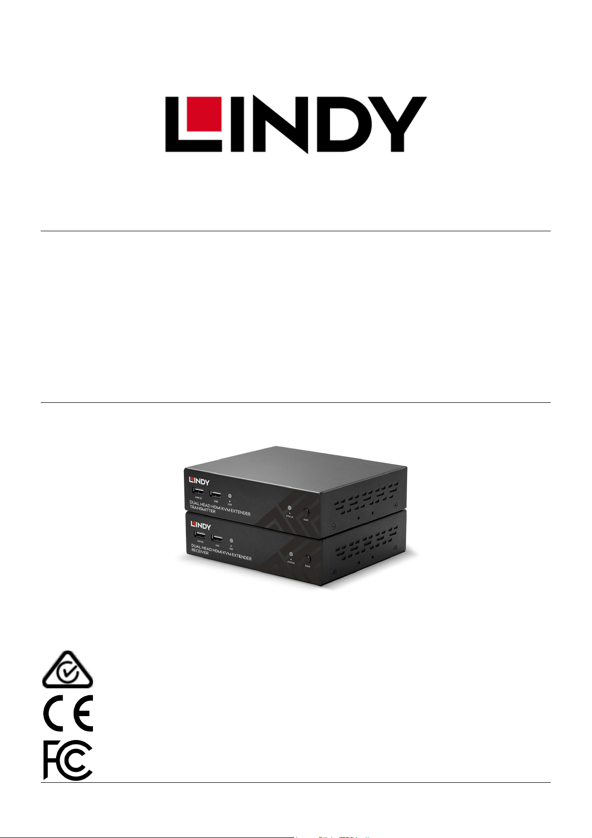
100m HDBaseT Cat.6 Dual Head HDMI,
USB, IR & RS-232 KVM Extender
User Manual English
Benutzerhandbuch Deutsch
Manuel Utilisateur Français
Manuale Italiano
No. 39374
lindy.com
comply with
Standards
© LINDY Group - SECOND EDITION (November 2020)
Page 2

© LINDY Group - SECOND EDITION (November 2020)
Page 3

!!! IMPORTANT !!!
Only use a direct cat.5e/6/7 cable connection
between the HDBaseT ports. Do not connect
these ports to a Network or Ethernet equipment
!!! WICHTIG !!!
Verwenden Sie AUSSCHLIEßLICH eine direkte
Kabelverbindung zwischen den HDBaseT
Anschlüssen aber NIEMALS eine
Netzwerkverbindung oder Ethernet oder
irgendwelche aktiven Komponenten
!!! ATTENTION !!!
N'utilisez qu'une connexion par câble Ethernet
directe entre les ports, sans passer par le
réseau Ethernet, un commutateur ou un
quelconque périphérique connecté à votre
réseau!
!!! IMPORTANTE !!!
Utilizzate un cavo dedicato per la connessione
tra le due unita’, non collegatelo ad uno rete
Ethernet o ad altri component attivi.
Page 4

User Manual English
Safety Instructions
! WARNING !
Please read the following safety information carefully and always keep this document with
the product.
Failure to follow these precautions can result in serious injuries or death from electric
shock, fire or damage to the product.
Touching the internal components or a damaged cable may cause electric shock, which
may result in death.
To reduce risk of fire, electric shocks or damage:
Do not open the product. There are no user serviceable parts inside.
Qualified servicing personnel must only carry out any repairs or maintenance.
Never use damaged cables.
Do not expose the product to water or places of moisture.
This product is intended for indoor use only.
Do not place the product near direct heat sources. Always place it in a well-ventilated place.
Do not place heavy items on the product or the cables.
Please ensure any adapters are firmly secured and locked in place before inserting into a wall socket
Page 5

User Manual English
Introduction
Thank you for purchasing the 100m Cat.6 Dual Head HDMI, USB & RS-232 Extender. This product has
been designed to provide trouble free, reliable operation. It benefits from both a LINDY 2-year warranty
and free lifetime technical support. To ensure correct use, please read this manual carefully and retain it
for future reference.
This dual head KVM extender is capable of transmitting two 1920x1080@60Hz video signals, USB, bidirectional IR, serial, digital and analogue audio, all over HDBaseT2.0 using a single Cat.6 (or higher)
cable in a point to point configuration. This allows for the creation of a remote-control zone with a dual
display set up.
Package Contents
100m Cat.6 Dual Head HDMI, USB & RS-232 Transmitter
100m Cat.6 Dual Head HDMI, USB & RS-232 Receiver
2 x 12VDC 1.5A multi-country power supply (UK, EU, US & AUS adapters), barrel size: 5.5 / 2.1mm
2 x IR transmitter cable, 1.4m
2 x IR receiver cable, 1.4m
USB type A (male) to Mini-B (male), 1m
8 x Rubber feet
4 x Screw type HDMI cable stand-offs
Lindy manual
Features
Transmit 2 1920x1080@60Hz signals up to 100m & USB using HDBaseT over a single Cat.6 cable.
Compatible with various USB devices including printers & scanners, storage drives, hubs & human
interface devices (HID) such as mice, keyboards and webcams.
Supports both RS-232 controls and bi-directional IR.
Analogue & digital audio pass-through allows the connection of amplifiers, speakers and microphones.
HDCP support ensures maximum compatibility with copy protected content.
Specification
HDMI standard: 1.4
HDBaseT Standard: HDBaseT 2.0
Chipset: VS2K series
Maximum bandwidth: 8.92Gbps
Max resolution: 1920x1080p @ 60Hz 4:4:4 8bit
Supported audio formats: 2 channel stereo audio, digital audio formats up to 7.1 channel.
Maximum Input / Output HDMI cable length: 2m (6.56ft)
Transmission medium: Cat.6 (or higher)
Control methods: RS-232 & IR
HDCP support: 1.4
Storage temperature: -20°C - 60°C (-4°F - 140°F)
Operating temperature: 0°C - 50°C (32°F - 122°F)
Humidity: 0-85% RH (non-condensing)
Housing material: Metal
Power requirement: 2 x 12VDC 1.5A
HDBaseT™ and the HDBaseT Alliance logo are trademarks of the HDBaseT Alliance.
Page 6
User Manual English
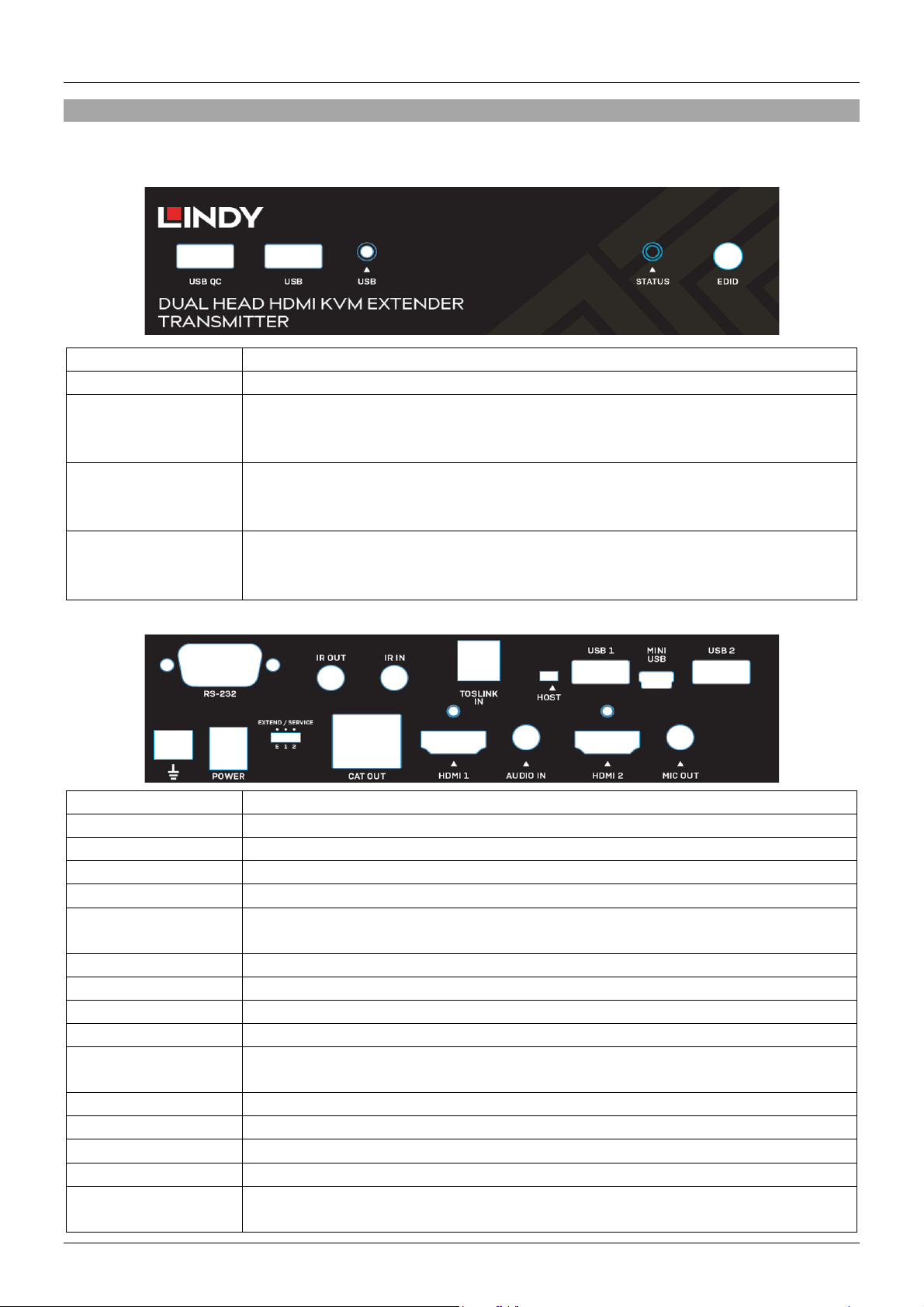
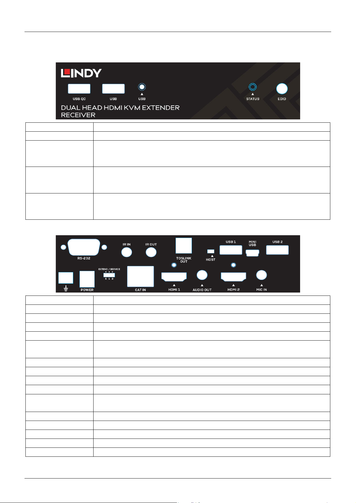
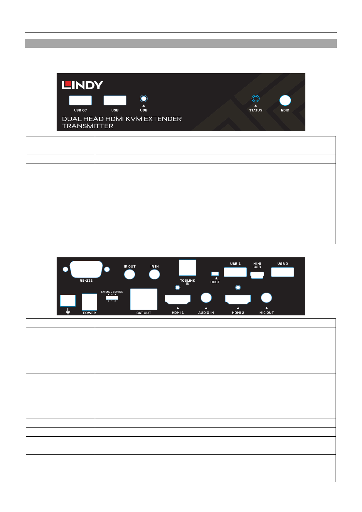
USB QC
Connect USB devices. This port also supports Quick Charge.
USB
Connect USB devices.
▲USB LED
The USB LED will emit a solid orange light when there are no USB devices
▲STATUS LED
The status LED will emit a solid green light when there is a successful link
EDID
The EDID button is used to copy the EDID of each display from each source.
RS-232
Connect to a PC for serial control.
IR OUT
Connect an IR transmitter.
IR IN
Connect an IR receiver.
TOSLINK IN
Connect a TOSLINK (optical) cable from a PC to pass-through digital audio.
HOST
Please see the “Installation & Operation” section of this manual for detail.
USB 1
Connect a USB device. Please note: When the “Host” Switch is set to “Host”
MINI USB
Connect to a PC or Laptop.
USB 2
Connect a USB device.
GROUND
Ground connection
POWER
Connect an included 12VDC 1.5A multi-country power supply.
EXTEND / SERVICE
Extend / Service switch assists in serial control. Please see the “Installation &
CAT OUT
Connect up to a 100m (328.08ft) Cat.6 (or higher) cable.
HDMI 1
Connect an HDMI cable from a PC.
AUDIO IN
Connect a 3.5mm stereo audio cable from a PC to pass-through analogue audio.
HDMI 2
Connect an HDMI cable from a PC.
MIC OUT
Connect a 3.5mm audio cable to pass-through a microphone input from the
Overview
Transmitter
Front Panel:
detected. When USB devices are detected, the LED will intermittently flash “x”
times depending on how many devices are detected (between 1 and 4).
between the transmitter and receiver. It will emit a solid red light when there is
no link detected.
Rear Panel:
Please see the “Installation & Operation” section of this manual for instruction
on copying EDID’s.
this port will only provide power to the USB device.
Operation” section of this manual for full detail.
receiver.
Page 7
User Manual English
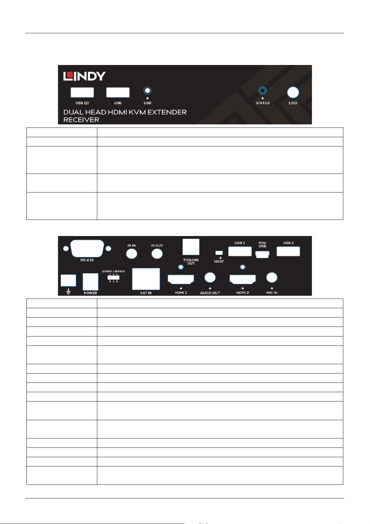
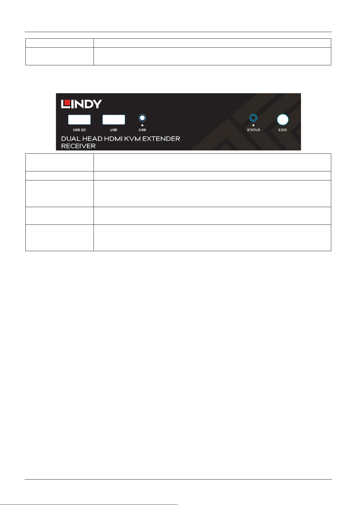
USB QC
Connect USB devices. This port also supports Quick Charge.
USB
Connect USB devices.
▲USB LED
The USB LED will emit a solid orange light when there are no USB devices
▲STATUS LED
The Status LED shows current links between the transmitter and receiver.
EDID
The EDID button is used to copy the EDID of each display from each source.
RS-232
Connect to a serial control device.
IR IN
Connect an IR receiver.
IR OUT
Connect an IR transmitter.
TOSLINK OUT
Connect a TOSLINK (optical) cable to an amplifier or active speaker system.
HOST
Please see the “Installation & Operation” section of this manual for detail.
USB 1
Connect a USB device. Please note: When the “Host” Switch is set to “Host”
MINI USB
Connect to a PC or Laptop.
USB 2
Connect a USB device.
GROUND
Ground connection
POWER
Connect an included 12VDC 1.5A multi-country power supply.
EXTEND / SERVICE
Extend / Service switch assists in serial control. Please see the “Installation &
Operation” section of this manual for full detail.
CAT IN
Connect up to a 100m (328.08ft) Cat.6 (or higher) cable to establish a link
HDMI 1
Connect an HDMI cable to a display or projector
AUDIO OUT
Connect a 3.5mm stereo audio cable to an amplifier or speakers.
HDMI 2
Connect an HDMI cable to a display or projector.
MIC IN
Connect a 3.5m audio cable to pass-through a microphone input from the
Receiver
Front Panel:
detected. When USB devices are detected, the LED will intermittently flash “x”
times depending on how many devices are detected (between 1 and 4).
Please see the “Installation & Operation” section of the manual for full details.
Please see the “Installation & Operation” section of this manual for instruction
on copying EDID’s.
Rear Panel:
this port will only provide power to the USB device.
between the transmitter and receiver.
receiver.
Page 8

User Manual English
Installation & Operation
For installation of this extender, please follow the steps below. Before installation ensure that all devices
are powered off. This installation example will be for a dual screen configuration. To install this product
using a single display, take care to connect a single HDMI cable from the source device.
Please note: Before completing the installation process, we recommend that all products are properly
grounded. For the transmitter and receiver, this can be done using the ground terminal on the bottom left
of the rear panel on both units.
1. Using two HDMI cables, connect two HDMI ports on a PC or graphics card to the HDMI 1 and 2 Ports
on the transmitter.
2. Connect the included Mini USB cable to the “Host” port on the transmitter and a USB Type A port on
the PC.
3. In order to control the source PC over serial, connect a serial cable from the female RS-232 port on
the transmitter to the PC.
4. For audio pass-through. Connect either a TOSLINK (optical) or 3.5mm stereo audio cable from the
source PC to the “TOSLINK IN” or “AUDIO IN” ports on the transmitter respectively. To add a
microphone input, connect a 3.5mm audio cable from the “MIC OUT” port on the transmitter to a mic
input on the source PC.
5. Connect either the IR receiver or IR transmitter cable to the “IR IN” or “IR OUT” ports respectively for
IR control. This operates bi-directionally.
6. Connect one end of a Cat.6 (or higher) cable to the “CAT OUT” port on the transmitter.
7. Take the other end of the Cat.6 cable and connect this to the “CAT IN” port on the receiver. This will
establish an HDBaseT connection between the two units.
8. Using two HDMI cables, connect the HDMI ports on the receiver to an HDMI port on each display.
9. For serial control, connect the male RS-232 port on the receiver to a serial device.
10. Connect any audio devices to the receiver using either a TOSLINK (optical) or 3.5mm stereo audio
cable.
11. Connect a microphone to the “MIC IN” port on the receiver.
12. Connect USB HID: mice, keyboards, hubs, printers, scanners etc to the receiver using the USB Ports
on the receiver.
13. Connect both 12VDC 1.5A multi-country power supply to power outlets and the “POWER” ports on the
transmitter receiver.
14. Power on the displays, and finally the source device.
EDID Button
To copy an EDID from an individual, or dual displays, press down the EDID button on the front panel of
either the transmitter or receiver for 3 seconds. The status LED will begin to flash alternate colours. The
EDID has been successfully copied.
To enable EDID pass-through, press down the EDID button on the transmitter or receiver for 6 seconds.
This will also reset a previously copied EDID.
Host Switch
The host switch is used to determine where the source PC is controlled from. To control the source PC
from the remote location, ensure the switch is set to the “Host” position on the receiver. It is vital that when
it is set up in this way, that the corresponding unit is not set to the “Host” position.
Extend / Service Switch
The Extend / Service switch allows for the extension of serial control. Please ensure this is always set to
the “E” position. Positions 1 and 2 are designated for future firmware updates.
Page 9
User Manual English
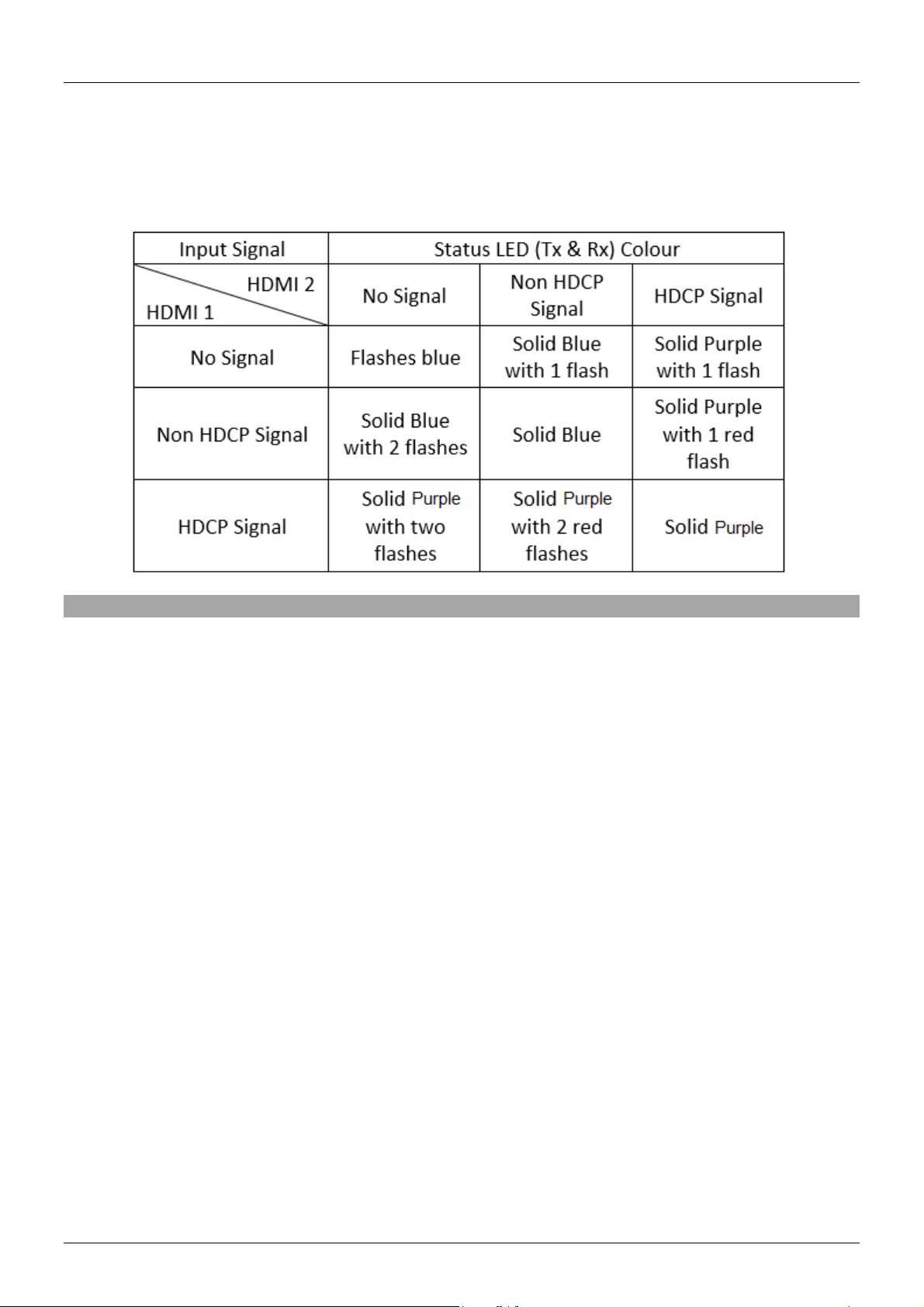
Status LED
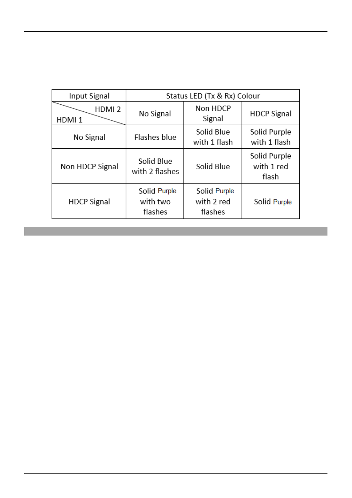
The status LED’s on the transmitter and receiver will illuminate depending on the type of transmission that
is established. When no connection is present, the LED on the transmitter will emit a solid green light, and
on the receiver a solid red light. Please see the table below which shows how the status LED illuminates
depending on the input signal.
Troubleshooting
After carefully reading the installation section of this manual, If you are having any issues, please consult
the troubleshooting information below:
There is no display on the screen.
Check that all connections between all components are secure in the appropriate ports.
Check that the DC plug and jacks are firmly connected, and the LED’s are illuminated.
Power off all devices, then power back on in the following order, the transmitter, the receiver, both
displays and finally the source device(s).
Some display devices may have trouble successfully establishing a ‘handshake’ unplug and re-connect
the HDMI cables from the display.
Check the length of HDMI cable(s) used between the source and transmitter, and the receiver and
displays. If the cables exceed the maximum lengths outlined in the specification, please reduce the
length of cable.
Reduce the length of Cat.6 cable used or try a higher quality cable.
USB devices are not working.
Ensure that the correct host device is selected using the “HOST” switch on the receiver, and the switch
is set in the opposite direction on the transmitter.
Check that the connection between the “HOST” port on the transmitter, and the source PC is secure.
Check that no USB devices are connected to the inactive unit.
Try connecting another USB device (there may be incompatibilities using asynchronous devices)
Power cycle the extender.
Page 10

Benutzerhandbuch Deutsch
Sicherheitshinweise
! GEFAHR !
Bitte lesen Sie die folgenden Sicherheitshinweise sorgfältig durch und bewahren Sie dieses
Dokument immer zusammen mit dem Produkt auf.
Die Nichtbeachtung dieser Vorsichtsmaßnahmen kann zu schweren Verletzungen oder
zum Tod durch Stromschlag, Feuer oder Schäden am Produkt führen.
Das Berühren der internen Komponenten oder eines beschädigten Kabels kann einen
elektrischen Schlag verursachen, der zum Tod führen kann.
Um die Gefahr von Bränden, Stromschlägen oder Schäden zu verringern:
Öffnen Sie das Produkt nicht. Es befinden sich keine vom Benutzer zu wartenden Teile im Inneren.
Ausschließlich qualifiziertes Personal darf Reparaturen oder Wartungen durchführen.
Verwenden Sie niemals beschädigte Kabel.
Setzen Sie das Produkt nicht Wasser oder Feuchtigkeit aus.
Dieses Produkt ist nur für den Gebrauch in geschlossenen Räumen bestimmt.
Stellen Sie das Produkt nicht in der Nähe von direkten Wärmequellen auf. Stellen Sie es immer an
einem gut belüfteten Ort auf.
Stellen Sie keine schweren Gegenstände auf das Produkt oder die Kabel.
Bitte stellen Sie vor der Verwendung sicher, dass alle Adapter sicher und fest eingerastet sind.
Page 11

Benutzerhandbuch Deutsch
Einführung
Wir freuen uns, dass Ihre Wahl auf ein LINDY-Produkt gefallen ist und danken Ihnen für Ihr Vertrauen. Sie
können sich jederzeit auf unsere Produkte und einen guten Service verlassen. Dieser 100m Cat.6 Dual
Head HDMI, USB & RS232 Extender unterliegt einer 2-Jahres LINDY Herstellergarantie und
lebenslangem kostenlosen, technischen Support. Bitte lesen Sie diese Anleitung sorgfältig und bewahren
Sie sie auf.
Dieser Dual Head Extender ist in der Lage, zwei 1920x1080@60Hz Videosignale, USB, bidirektionales
IR, serielle Daten sowie digitales und analoges Audio mit einem Cat.6-Kabel (oder höher) über
HDBaseT2.0 in einer Punkt-zu-Punkt-Konfiguration zu übertragen. So kann eine Bedienkonsole mit zwei
Displays digital vom Rechner abgesetzt werden.
Lieferumfang
100m Cat.6 Dual Head HDMI, USB & RS232 Transmitter
100m Cat.6 Dual Head HDMI, USB & RS232 Receiver
2 x 12VDC 1.5A Multi-Country Netzteil (mit Adaptern: UK, EU, US & AUS ), DC-Hohlstecker: 5.5 /
2.1mm
2 x IR-Senderkabel, 1.4m
2 x IR-Empfängerkabel, 1.4m
USB-Stecker Type A an Mini-B, 1m
8 x Gummifüße
4 x HDMI-Anschlussschraube
Lindy Handbuch
Eigenschaften
Überträgt zwei 1920x1080@60Hz-Signale sowie USB bis zu 100m mit einem Cat.6 Kabel über
HDBaseT
Kompatibel mit einer Vielzahl von USB-Geräten inklusive Druckern und Scannern, Speichermedien,
Hubs & Human-Interface-Geräten (HID) wie Mäuse, Tastaturen oder Webcams
Unterstützt RS232-Fernbedienung und bidirektionales IR
Analoges & digitales Audio Pass-through erlaubt den Anschluss von Verstärkern, Lautsprechern und
Mikrofonen
HDCP-Unterstützung sorgt für maximale Kompatibilität mit kopiergeschützten Inhalten
Spezifikationen
HDMI-Standard 1.4
HDBaseT-Standard: HDBaseT 2.0
Chipsatz: VS2K-Serie
Maximale Bandbreite / Max Auflösung: 8.92Gbit/s / 1920x1080p @ 60Hz 4:4:4 8bit
Unterstützte Audioformate: 2-Kanal-Stereo-Audio, digitale Audioformate bis 7.1-Kanal
Maximale HDMI-Kabellänge am Eingang / Ausgang: 2m (6.56ft)
Übertragungsmedium: Cat.6 (oder höher)
Fernbedienung über RS232 & IR
HDCP-Unterstützung: 1.4
Lagertemperatur / Betriebstemperatur: -20°C - 60°C (-4°F - 140°F) / 0°C - 50°C (32°F - 122°F)
Feuchtigkeit: 0-85% RH (nicht kondensierend)
Gehäusematerial: Metall
Leistungsaufnahme: 2 x 12VDC 1.5A
HDBaseT™ und das HDBaseT Alliance Logo sind Warenzeichen der HDBaseT Alliance.
Page 12
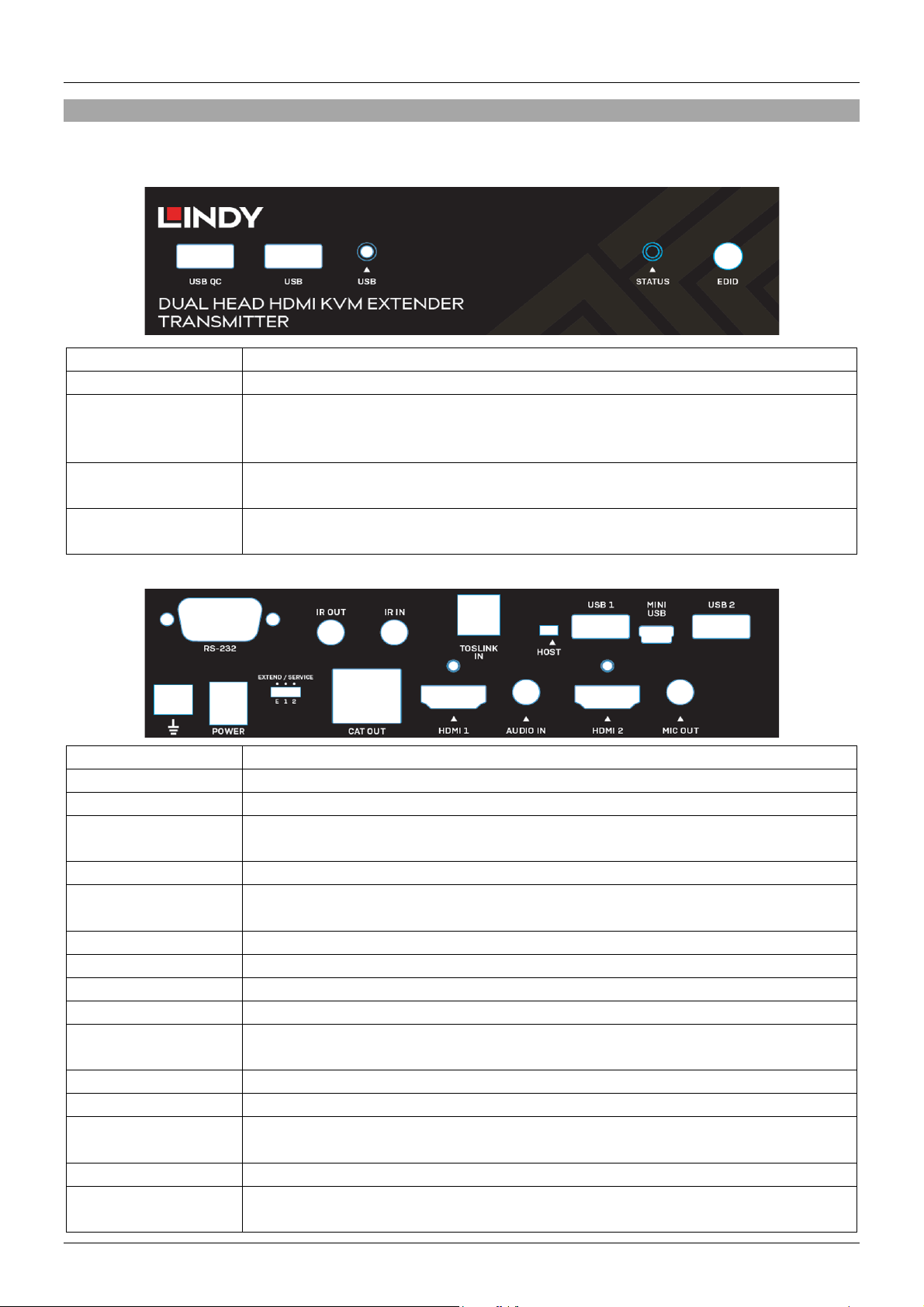
Benutzerhandbuch Deutsch
USB QC
Zum Anschluss von USB-Geräten; unterstützt auch Quick Charge.
USB
Zum Anschluss von USB-Geräten
▲USB LED
Wenn keine USB-Geräte erkannt werden, leuchtet die USB-LED orange. Wenn
▲STATUS LED
Die Status-LED leuchtet bei erfolgreicher Verbindung zwischen Transmitter und
Receiver grün. Sie leuchtet rot, wenn keine Verbindung zustande kommt.
EDID
Die EDID-Taste wird zum Kopieren der EDID jedes Displays von jeder Quelle
RS-232
Anschluss an einen PC für serielle Bedienung
IR OUT
Anschluss eines IR-Transmitters
IR IN
Anschluss eines IR-Receivers
TOSLINK IN
Anschluss eines optischen TOSLINK-Kabels vom PC für digitales Audio PassHOST
Weitere Informationen hierzu finden Sie unter “Installation & Betrieb”.
USB 1
Anschluss eines USB-Geräts. Achtung: Wenn der “Host”-Schalter auf “Host”
gestellt ist, versorgt dieser Port das USB-Gerät nur mit Strom.
MINI USB
Anschluss von PC oder Laptop
USB 2
Anschluss eines USB-Geräts
GROUND
Erdung
POWER
Anschluss des mitgelieferten 12VDC 1.5A Multi-Country Netzteils
EXTEND / SERVICE
Der Schalter ‘Extend / Service’ unterstützt bei der seriellen Bedienung. Weitere
Informationen hierzu finden Sie unter “Installation & Betrieb”.
CAT OUT
Anschluss eines 100m (328.08ft) Cat.6-Kabel (oder höher)
HDMI 1
Anschluss eines HDMI-Kabels vom PC
AUDIO IN
Anschluss eines 3.5mm Stereo-Audiokabels vom PC für analoges Audio PassHDMI 2
Anschluss eines HDMI-Kabels vom PC
MIC OUT
Anschluss eines 3.5mm Audiokabels zum Durchleiten eines
Übersicht
Transmitter
Vorderseite:
USB-Geräte erkannt werden, blinkt die LED so viele Male auf, wie Geräte
erkannt werden (zwischen 1 und 4).
Rückseite:
verwendet. Weitere Informationen finden Sie unter “Installation & Betrieb”.
through.
through.
Mikrofoneingangssignals vom Receiver.
Page 13
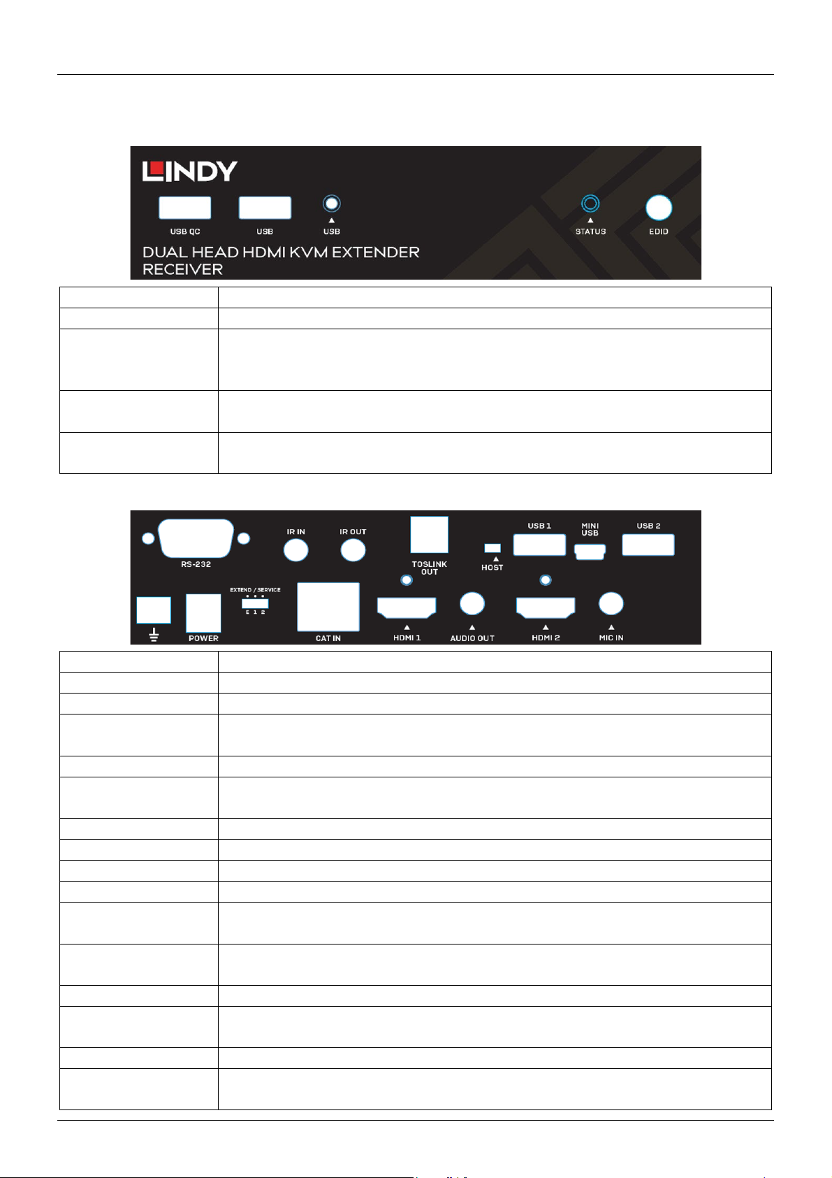
Benutzerhandbuch Deutsch
USB QC
Zum Anschluss von USB-Geräten; unterstützt auch Quick Charge.
USB
Zum Anschluss von USB-Geräten
▲USB LED
Wenn keine USB-Geräte erkannt werden, leuchtet die USB-LED orange. Wenn
▲STATUS LED
Die Status-LED zeigt aktuelle Verbindungen zwischen Transmitter und Receiver
EDID
Die EDID-Taste wird zum Kopieren der EDID jedes Displays von jeder Quelle
RS-232
Anschluss eines seriellen Steuergeräts
IR IN
Anschluss eines IR-Receivers
IR OUT
Anschluss eines IR-Transmitters
TOSLINK OUT
Anschluss eines optischen TOSLINK-Kabels an einen Verstärker oder an ein
HOST
Weitere Informationen hierzu finden Sie unter “Installation & Betrieb”.
USB 1
Anschluss eines USB-Geräts. Achtung: Wenn der “Host”-Schalter auf “Host”
MINI USB
Anschluss von PC oder Laptop
USB 2
Anschluss eines USB-Geräts
GROUND
Erdung
POWER
Anschluss des mitgelieferten 12VDC 1.5A Multi-Country Netzteils
EXTEND / SERVICE
Der Schalter ‘Extend / Service’ unterstützt bei der seriellen Bedienung. Weitere
Informationen hierzu finden Sie unter “Installation & Betrieb”.
CAT IN
Anschluss eines 100m-langen (328.08ft) Cat.6-Kabels (oder höher) um eine
HDMI 1
Anschluss eines HDMI-Kabels an ein Display oder einen Projektor
AUDIO OUT
Anschluss eines 3.5mm Stereo-Audiokabels an einen Verstärker oder
HDMI 2
Anschluss eines HDMI-Kabels an ein Display oder einen Projektor
MIC IN
Anschluss eines 3.5mm Audiokabels zum Durchleiten eines
Mikrofoneingangssignals vom Receiver.
Receiver
Vorderseite:
USB-Geräte erkannt werden, blinkt die LED so viele Male auf, wie Geräte
erkannt werden (zwischen 1 und 4).
an. Weitere Informationen finden Sie unter “Installation & Betrieb”.
verwendet. Weitere Informationen finden Sie unter “Installation & Betrieb”.
Rückseite:
aktives Lautsprechersystem.
gestellt ist, versorgt dieser Port das USB-Gerät nur mit Strom.
Verbindung zwischen Transmitter und Receiver herzustellen.
Lautsprecher.
Page 14

Benutzerhandbuch Deutsch
Installation & Betrieb
Folgen Sie zur Installation dieses Extenders bitte den untenstehenden Anweisungen. Zunächst stellen Sie
sicher, dass die Geräte ausgeschaltet sind. Dieses Installationsbeispiel bezieht sich auf eine Konfiguration
mit zwei Bildschirmen. Bei der Installation mit einem Display achten Sie bitte darauf, dass ein HDMI-Kabel
vom Quellgerät aus angeschlossen wird.
Achten Sie darauf, dass vor dem Abschluss der Installation alle Geräte geerdet sind. Dies ist bei
Transmitter und Receiver mit dem Erdungsanschluss unten links an der Rückseite beider Einheiten
möglich.
1. Verbinden Sie mit zwei HDMI-Kabeln zwei HDMI Ports eines PCs oder einer Grafikkarte mit den
HDMI Ports 1 und 2 des Transmitters.
2. Schließen Sie das mitgelieferte Mini-USB-Kabel am “Host” Port des Transmitters an und am USB
Typ A Port des PCs.
3. Zur seriellen Steuerung des Quell-PCs schließen Sie ein serielles Kabel am RS232 Port des
Transmitters und am PC am.
4. Für Audio Pass-through verbinden Sie den Quell-PC mit einem optischen TOSLINK- oder 3.5mm
Stereo-Audiokabel mit dem “TOSLINK IN” oder “AUDIO IN” Port des Transmitters. Um einen
Mikrofoneingang hinzuzufügen, schließen Sie ein 3.5mm Audiokabel am “MIC OUT” Port des
Transmitters und an einem Mikrofoneingang des Quell-PCs an.
5. Verbinden Sie entweder das IR-Empfänger- oder Senderkabel mit dem “IR IN” oder “IR OUT” Port
zur Infrarotsteuerung (bidirektional).
6. Verbinden Sie ein Ende eines Cat.6-Kabels (oder höher) mit dem Port “CAT OUT” auf dem
Transmitter.
7. Das andere Ende des Cat.6-Kabels schließen Sie am “CAT IN” Port des Receivers an, um eine
HDBaseT-Verbindung zwischen Transmitter und Receiver einzurichten.
8. Mit zwei HDMI-Kabeln verbinden Sie die HDMI Ports am Receiver mit dem HDMI Port der Displays.
9. Zur seriellen Steuerung verbinden Sie den RS232 Port am Receiver mit einem seriellen Gerät.
10. Audiogeräte können mit einem optischen TOSLINK- oder 3.5mm Stereo-Audiokabel am Receiver
angeschlossen werden.
11. Ein Mikrofon schließen Sie am “MIC IN” Port des Receivers an.
12. Anschluss von USB HID-Geräten: Mäuse, Tastaturen, Hubs, Drucker, Scanner etc. werden über
die USB Ports am Receiver angeschlossen.
13. Schließen Sie beide 12VDC 1.5A Multi-Country Netzteile an Steckdosen und den “POWER” Ports
von Transmitter und Receiver an.
14. Schalten Sie die Displays ein und zum Schluss das Quellgerät.
EDID-Taste
Um die EDID von einem oder zwei Displays zu kopieren, drücken Sie 3 Sekunden lang die EDID-Taste
auf der Vorderseite von Transmitter oder Receiver. Die Status-LED wird anfangen in verschiedenen
Farben zu blinken und die EDID-Daten sind kopiert.
Für EDID Pass-through drücken Sie 6 Sekunden lang die EDID-Taste auf Transmitter oder Receiver.
Dadurch wird auch die zuvor kopierte EDID zurückgesetzt.
Host-Schalter
Mit diesem Schalter wird festgelegt, von wo der Quell-PC gesteuert wird. Um den Quell-PC vom
abgesetzten Arbeitsplatz aus zu bedienen, muss der Schalter auf der “Host”- Position des Receivers
stehen. In diesem Fall darf der Schalter beim Transmitter nicht auf der Position “Host” stehen.
Page 15
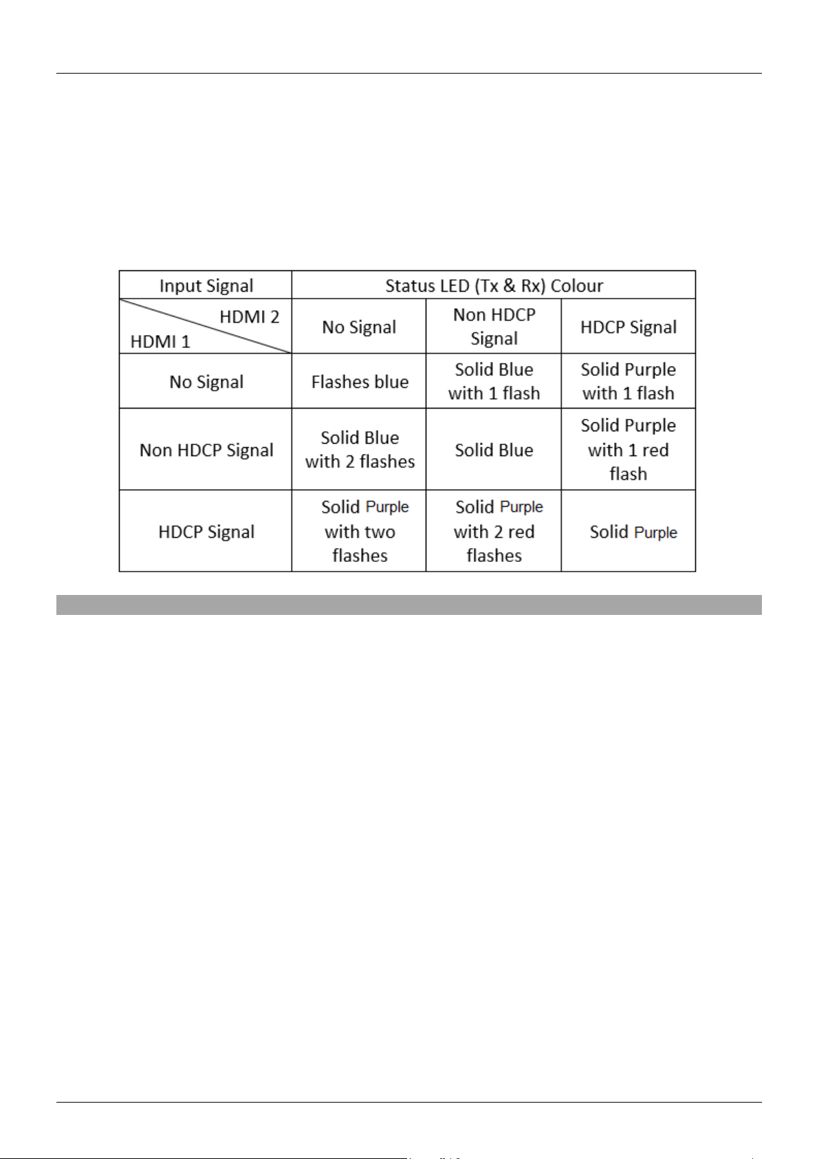
Benutzerhandbuch Deutsch
‘Extend / Service’-Schalter
Dieser Schalter erlaubt die Verlängerung der seriellen Steuerung. Achten Sie darauf, dass der Schalter
immer auf Position “E” steht. Die Positionen 1 und 2 sind für zukünftige Firmwareupdates vorgesehen.
Status-LED
Die Status-LEDs am Transmitter und Receiver leuchten je nach Art der Verbindung. Wenn keine
Verbindung zustande kommt, leuchtet die LED auf dem Transmitter grün und auf dem Receiver rot. In der
Tabelle unten sehen Sie, wie die LED abhängig vom Eingangssignal leuchtet.
Fehlersuche
Wenn das Display kein Bild zeigt:
Stellen Sie sicher, dass alle Verbindungen zwischen den Komponenten sicher und an den richtigen
Ports angeschlossen sind.
Stellen Sie sicher, dass die Stromstecker fest angeschlossen sind und dass die LEDs leuchten.
Schalten Sie alle Geräte aus und in der folgenden Reihenfolge wieder ein: Transmitter, Receiver, beide
Displays und zum Schluss die Quellgeräte.
Einige Displays können Probleme beim ‘Handshake’ haben. In diesem Fall ziehen Sie das HDMI-Kabel
vom Display ab und verbinden es erneut.
Überprüfen Sie die Länge der HDMI-Kabel zwischen Quelle und Transmitter sowie zwischen Receiver
und Displays. Wenn die Kabel die in der Spezifikation genannten maximalen Längen überschreiten,
verwenden Sie bitte kürzere Kabel.
Reduzieren Sie die Länge des verwendeten Cat.6-Kabels oder nehmen Sie ein höherwertiges Kabel.
Wenn die USB-Geräte nicht funktionieren:
Vergewissern Sie sich, dass das korrekte Hostgerät mit dem “HOST”-Schalter des Receivers
ausgewählt wurde und dass der Schalter auf dem Transmitter auf der entgegengesetzten Position
steht.
Prüfen Sie, ob die Verbindung zwischen dem “HOST” Port des Transmitters und dem Quell-PC sicher
ist.
Stellen Sie sicher, dass keine USB-Geräte an einer inaktiven Einheit angeschlossen sind
Versuchen Sie, ein anderes USB-Geräte anzuschließen (es kann Inkompatibilitäten bei der
Verwendung asynchroner geräte geben)
Schalten Sie den Extender aus und wieder ein.
Page 16

Manuel Utilisateur Français
Consignes de sécurité
! ATTENTION !
Merci de lire attentivement ces instructions de sécurité et de les conserver avec le produit.
Le non-respect de ces précautions peut causer un choc électrique entrainant des blessures
graves, voire mortelles, un incendie ou des dommages au produit.
Toucher les composants internes ou un câble endommagé peut provoquer un choc
électrique pouvant entraîner la mort.
Pour éviter les risques d'incendie, de choc électrique ou de dommages:
Ne pas ouvrir le produit. Il ne contient pas d'éléments réparables.
Les opérations de réparation ou d'entretien ne doivent être effectués que par du personnel qualifié et
habilité.
Ne jamais utiliser de câble endommagé.
Ne pas mouiller le produit et ne pas l'exposer à l'humidité.
Ce produit est réservé à un usage en intérieur.
Ne pas placer le produit à proximité de sources de chaleur. Toujours le placer dans un endroit
suffisamment ventilé.
Ne pas déposer de charge lourde sur le produit ou sur les câbles.
Veuillez vous assurer que l'adaptateur utilisé est fermement fixé et verrouillé en place avant de l'insérer
dans une prise murale.
Page 17

Manuel Utilisateur Français
Introduction
Nous sommes heureux que votre choix se soit porté sur un produit LINDY et vous remercions de votre
confiance. Vous pouvez compter à tout moment sur la qualité de nos produits et de notre service. Cet
Extender Dual Head HDMI Cat.6, USB & RS-232 100m est soumis à une durée de garantie LINDY de 2
ans et d’une assistance technique gratuite à vie. Merci de lire attentivement ces instructions et de les
conserver pour future référence.
Cet extender Dual Head est capable de transmettre deux signaux vidéo 1920x1080@60Hz, USB, IR
bidirectionnel, série, numérique et audio analogique, en HDBaseT2.0 en utilisant un seul câble Cat.6 (ou
supérieur) dans une configuration point à point. Ceci permet la création d'une zone de contrôle à distance
avec un double affichage.
Contenu de l’embellage
Emetteur Cat.6 Dual Head HDMI, USB & RS-232 100m (Transmitter)
Récepteur Cat.6 Dual Head HDMI, USB & RS-232 100m (Receiver)
2 x alimentation multi-pays 12VDC 1.5A (adaptateurs UK, EU, US & AUS), prise DC: 5.5 / 2.1mm
2 x Câble émetteur IR, 1.4m
2 x Câble récepteur IR, 1.4m
Câble USB type A (mâle) vers Mini-B (mâle), 1m
8 x pied caoutchouc
4 x socles de câble HDMI à vis
Manuel LINDY
Caractéristiques
Transmet 2 signaux 1920x1080@60Hz jusqu’à 100m & USB en HDBaseT via un câble Cat.6.
Compatible avec une variété de périphériques USB incluant imprimantes & scanners, disques de
stockage, hubs & et interfaces HID comme les souris, claviers et webcams.
Prise en charge du contrôle RS-232 et IR bidirectionnel.
Bypass audio analogique et numérique permettant la connexion d’amplificateurs, haut-parleurs et
microphones.
Prise en charge HDCP pour un maximum de compatibilité avec les contenus protégés.
Spécification
Norme HDMI: 1.4
Norme HDBaseT: HDBaseT 2.0
Chipset: série VS2K
Bande passante maximale / Résolution maximale: 8.92Gbit/s / 1920x1080p @ 60Hz 4 :4 :4 8bit
Formats audios prise en charge: audio stéréo 2 canaux, formats audio numériques jusqu’à 7.1 canaux.
Longueur maximale de câbles HDMI en entrée / sortie: 5m (16.4ft)
Média de transmission: Cat.6 (ou supérieur)
Méthodes de contrôle: RS-232 & IR
Prise en charge HDCP: 1.4
Température de stockage: -20°C - 60°C (-4°F - 140°F)
Température de fonctionnement: 0°C - 50°C (32°F - 122°F)
Humidité relative: 0-85% RH (sans condensation)
Matériau du boitier: métal
Couleur: noir
Consommation électrique: 2 x 12VDC 1.5A
HDBaseT™ et le logo HDBaseT Alliance sont des marques déposées de l’HDBaseT Alliance.
Page 18
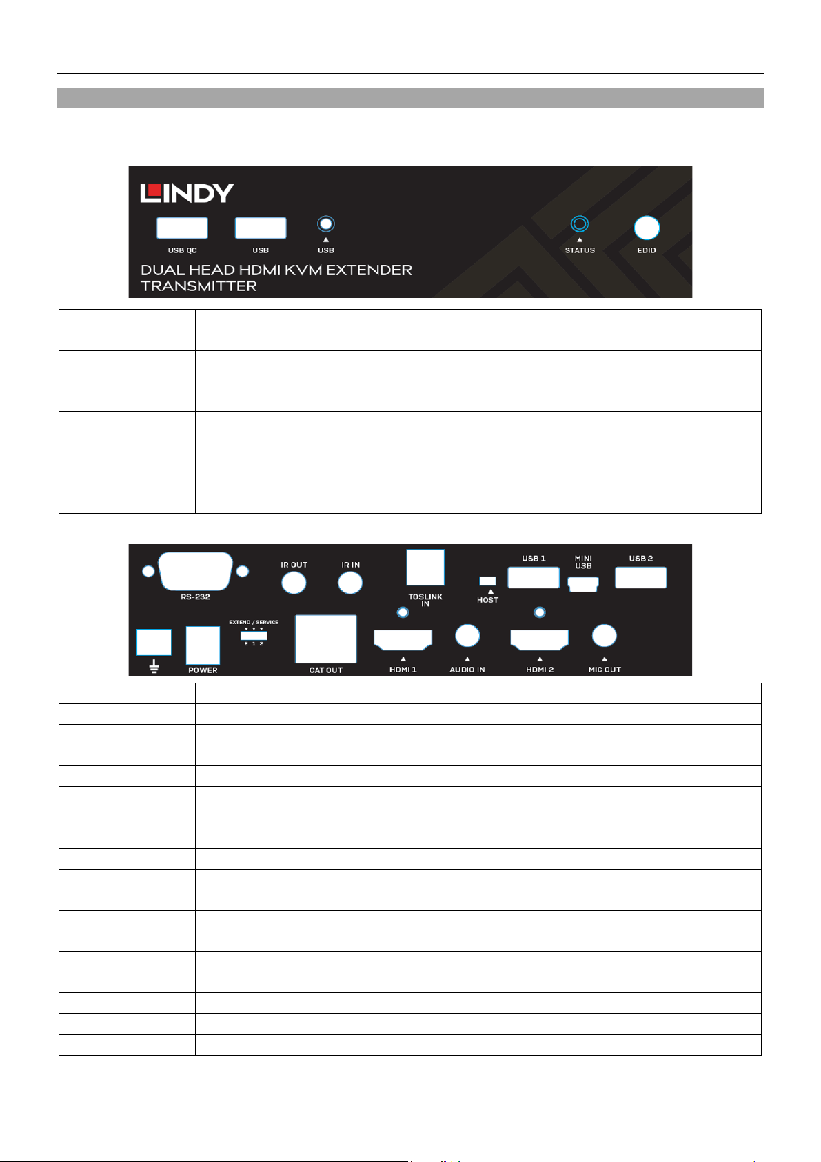
Manuel Utilisateur Français
USB QC
Connecte les périphériques USB. Ce port supporte aussi Quick Charge.
USB
Connecte les périphériques USB.
▲LED USB
La LED USB s’éclaire en orange fixe lorsqu’aucun périphérique USB n’est détecté.
▲LED STATUS
La LED d’état s’éclaire en vert lorsqu’une liaison est établie entre émetteur et
récepteur. Elle s’éclaire en rouge si la liaison n’est pas établie.
EDID
Le bouton EDID est utilisé pour copier l’EDID de chacun des écrans des sources.
instructions sur la copie d’EDID.
RS-232
Connecte un PC pour le contrôle par série.
IR OUT
Connecte un émetteur IR.
IR IN
Connecte un récepteur IR.
TOSLINK IN
Connecte un câble TOSLINK (optique) d’un PC pour le bypass audio numérique.
HOST
Voir la section “Installation & Utilisation” de ce manuel pour plus de détail.
USB 1
Connecte un périphérique USB. Note: si le sélecteur “Host” est positionné sur
“Host” ce port ne délivre que l’alimentation au périphérique USB.
MINI USB
Connecte un PC ou un PC ou Laptop.
USB 2
Connecte un périphérique USB.
GROUND
Connexion masse (Ground)
POWER
Connecte l’alimentation multi-pays 12VDC 1.5A fournie.
EXTEND /
SERVICE
Sélecteur Extend / Service pour le contrôle série. Voir la section “Installation &
Utilisation” de ce manuel pour plus de détail.
CAT OUT
Connecte un câble Cat.6 (ou supérieur) de jusqu’à 100m (328.08ft).
HDMI 1
Connecte un câble HDMI au PC.
AUDIO IN
Connecte un câble 3.5mm audio stéréo au PC pour le bypass audio analogique.
HDMI 2
Connecte un câble HDMI au PC.
MIC OUT
Connecte un câble 3.5mm audio pour le bypass entrée microphone du récepteur.
Vue d’ensemble
Emetteur
Panneau avant:
Si des périphériques USB sont détectés, la LED va flasher “x” fois en fonction du
nombre de périphériques (entre 1 et 4).
Panneau arrière:
Merci de vous référer à la section “Installation & utilisation” de ce manuel pour les
Page 19
Manuel Utilisateur Français
USB QC
Connecte les périphériques USB. Ce port supporte également Quick Charge.
USB
Connecte les périphériques USB.
▲USB LED
La LED USB s’éclaire en orange fixe lorsqu’aucun périphérique USB n’est
▲STATUS LED
La LED d'état indique les liaisons actuelles entre l'émetteur et le récepteur.
EDID
Le bouton EDID est utilisé pour copier l’EDID de chacun des écrans des sources.
les instructions sur la copie d’EDID.
RS-232
Connecte un périphérique de contrôle série.
IR IN
Connecte un récepteur IR.
IR OUT
Connecte un émetteur IR.
TOSLINK OUT
Connecte un câble TOSLINK (optique) d’amplificateur ou de haut-parleurs.
HOST
Voir la section “Installation & Utilisation” de ce manuel pour plus de détail.
USB 1
Connecte un périphérique USB. Note: si le sélecteur “Host” est positionné sur
“Host” ce port ne délivre que l’alimentation au périphérique USB.
MINI USB
Connecte un PC ou Laptop.
USB 2
Connecte un périphérique USB.
GROUND
Connexion de masse (Ground)
POWER
Connecte l’alimentation multi-pays 12VDC 1.5A fournie.
EXTEND / SERVICE
Sélecteur Extend / Service pour le contrôle série. Voir la section “Installation &
CAT IN
Connecte un câble Cat.6 (ou supérieur) de jusqu’à 100m (328.08ft).
HDMI 1
Connecte un câble HDMI à l’affichage.
AUDIO OUT
Connecte un câble 3.5mm audio stéréo d’amplificateur ou de haut-parleurs.
HDMI 2
Connecte un câble HDMI à l’affichage.
MIC IN
Connecte un câble 3.5m de microphone.
Récepteur
Panneau avant:
détecté. Si des périphériques USB sont détectés, la LED va flasher “x” fois en
fonction du nombre de périphériques (entre 1 et 4).
Veuillez consulter la section "Installation & Utilisation" du manuel pour plus de
détails.
Panneau arrière:
Merci de vous référer à la section “Installation & utilisation” de ce manuel pour
Utilisation” de ce manuel pour plus de détail.
Page 20

Manuel Utilisateur Français
Utilisation
Pour l'installation de cet extendeur, veuillez suivre les étapes ci-dessous. Avant l'installation, assurez-vous
que tous les appareils sont hors tension. Cet exemple d'installation s'applique à une configuration à double
écran. Pour installer ce produit avec un seul écran, veillez à connecter un seul câble HDMI à partir du
périphérique source.
Note: Avant de terminer le processus d'installation, nous recommandons que tous les produits soient
correctement mis à la terre. Pour l'émetteur et le récepteur, cela peut se faire à l'aide de la borne de masse
située en bas à gauche du panneau arrière des deux unités.
1. Avec deux câbles HDMI, connectez deux ports HDMI d’un PC ou d’une carte graphique sur les ports
HDMI 1 et 2 de l’émetteur.
2. Connectez le câble Mini USB fourni sur le port “Host” de l’émetteur et au port USB Type A de
l’ordinateur.
3. Afin de contrôler le PC source via série, connectez un câble série du port RS-232 femelle de l’émetteur
au PC.
4. Pour le bypass audio. Connectez un câble TOSLINK (optique) ou 3.5mm audio stéréo du PC source
au port “TOSLINK IN” ou “AUDIO IN” de l’émetteur. Pour ajouter un microphone, connectez un câble
audio 3.5mm du port “MIC OUT” sur l’émetteur à un port entrée micro sur le PC source.
5. Connectez un câble récepteur IR ou émetteur IR au port “IR IN” ou “IR OUT” pour le contrôle
infrarouge. Cette fonction est bidirectionnelle.
6. Connectez une extrémité du câble Cat.6 (ou supérieur) au port “CAT OUT” de l’émetteur.
7. Connectez ensuite l’autre extrémité du câble Cat.6 au port “CAT IN” du récepteur. Ceci va établir une
connexion HDBaseT entre les deux unités.
8. Avec deux câbles HDMI, connectez les ports HDMI du récepteur à un port HDMI de chaque affichage.
9. Pour le contrôle série, connectez le port RS-232 mâle du récepteur à un périphérique série.
10. Connectez un périphérique audio sur le récepteur en utilisant un câble TOSLINK (optique) ou 3.5mm
audio stéréo.
11. Connectez un microphone au port “MIC IN” sur le récepteur.
12. USB HID: souris, clavier, hubs, imprimantes, scanners, etc., se connectent au récepteur en utilisant
les ports USB sur le récepteur.
13. Connectez les deux alimentations multi-pays 12VDC 1.5A aux prises secteur et aux ports “POWER”
de l’émetteur et du récepteur.
14. Alimentez les affichages et finalement la source.
Bouton EDID
Pour copier l’EDID d’un seul ou des deux écrans, appuyez sur le bouton EDID sur le panneau avant de
l’émetteur ou du récepteur pendant 3 secondes. La LED d’état va commencer à clignoter en alternant les
couleurs. L’EDID a été copié avec succès.
Pour activer le bypass EDID, appuyez sur le bouton EDID de l’émetteur ou du récepteur pendant 6
secondes. Cela va également réinitialiser un EDID précédemment copié.
Sélecteur Host
Le sélecteur host est utilisé pour déterminer d’où est contrôlé le PC source. Pour contrôler le PC source
à distance, assurez-vous que le sélecteur est positionné sur “Host” sur le récepteur. Il est indispensable
que l'unité correspondante ne soit pas réglée sur la position "Host" lors de cette configuration.
Sélecteur Extend / Service
Le sélecteur Extend / Service permet d'étendre la commande série. Veillez à ce qu'il soit toujours réglé
sur la position "E". Les positions 1 et 2 sont destinées aux mises à jour futures du firmware.
Page 21
Manuel Utilisateur Français
LED Status
Les LED d'état de l'émetteur et du récepteur s'allument en fonction du type de transmission
établi. Lorsqu'il n'y a pas de connexion, la LED de l'émetteur émet une lumière verte fixe et celle
du récepteur une lumière rouge fixe. Veuillez consulter le tableau ci-dessous qui montre comment
la LED d'état s'allume en fonction du signal d'entrée.
Dépannage
Si vous avez des problèmes, après avoir lu attentivement la section d'installation de ce manuel, veuillez
consulter les informations de dépannage ci-dessous:
Aucune image ne s’affiche à l’écran.
Vérifiez que toutes les connexions entre les composants sont bien faites sur les ports requis.
Vérifiez que les connexions d’alimentation DC sont bien réalisées et que les LED soient bien allumées.
Arrêtez tous les appareils, puis démarrez les dans l’ordre suivant, émetteur, récepteur, les deux
affichages et finalement la(les) sources(s).
Certains affichages peuvent avoir du mal à établir une connexion (handshaking), débranchez et
rebranchez les câbles HDMI de l'écran.
Vérifiez les longueurs des câbles HDMI utilisés entre source et émetteur, et entre récepteur et
affichage. Si la longueur des câbles excède celles définies dans les spécifications, veuillez réduire
cette longueur.
Réduisez la longueur du câble Cat.6 utilisé ou changez de qualité de câble.
Les périphériques USB ne fonctionnent pas.
Assurez-vous que l’appareil hôte requis est bien sélectionné avec le sélecteur “HOST” du récepteur
et que le sélecteur situé sur l’émetteur soit positionné à l’opposé.
Vérifiez que la connexion entre le port “HOST” de l’émetteur et le PC source est bien faite.
Vérifiez qu’aucun périphérique USB n’est connecté sur l’unité inactive.
Essayez de connecter un autre périphérique USB (il peut y avoir des incompatibilités en utilisant des
périphériques asynchrones).
Redémarrez l’extender.
Page 22

Manuale Italiano
Istruzioni di sicurezza
! ATTENZIONE !
Per favore leggete la seguente informativa e conservate sempre questo documento con il
prodotto.
La mancata osservanza di queste precauzione può causare seri infortuni o la morte per
folgorazione, incendi o danneggiare il prodotto.
Toccare i componenti interni o un cavo danneggiato può causare uno shock elettrico che
può condurre alla morte.
Per ridurre il rischio di incendi, folgorazione o danni:
Non aprite il prodotto. Non esistono componenti utilizzabili all'interno.
La riparazione o manutenzione del prodotto può essere effettuata solo da personale qualificato.
Non utilizzare mai cavi danneggiati
Non fate entrare il prodotto in contatto con acqua e non utilizzatelo in luoghi umidi
Questo prodotto è pensato esclusivamente per utilizzi in luoghi chiusi
Non posizionate il prodotto nelle vicinanze di sorgenti di calore. Installatelo sempre in luoghi ben
Non appoggiate oggetti pesanti sul prodotto o sui cavi.
Vi preghiamo di assicurarvi che ogni adattatore sia fermamente inserito e bloccato in sede prima di
ventilati.
collegarlo a una presa di corrente.
Page 23

Manuale Italiano
Introduzione
Vi ringraziamo per aver acquistato l’Extender Cat.6 Dual Head HDMI, USB & RS-232 100m. Questo
prodotto è stato progettato per garantirvi la massima affidabilità e semplicità di utilizzo ed è coperto da 2
anni di garanzia LINDY oltre che da un servizio di supporto tecnico a vita. Per assicurarvi di farne un uso
corretto vi invitiamo a leggere attentamente questo manuale e a conservarlo per future consultazioni.
Questo extender dual head è in grado di trasmettere due segnali video 1920x1080@60Hz, USB, IR
bidirezionale, connessione seriale, audio digitale e analogico grazie ad un link HDBaseT 2.0 utilizzando
un singolo cavo Cat.6 (o superiore) in configurazione punto a punto. Questo consente di create postazioni
di controllo remote con due schermi.
Contenuto della confezione
Trasmettitore Dual Head HDMI, USB & RS-232 Cat.6 100m
Ricevitore Dual Head HDMI, USB & RS-232 Cat.6 100m
2 x alimentatore 12VDC 1.5A multi-country (UK, EU, US & AUS adapters), Dimensione connettore:
5.5 / 2.1mm
2 x Cavo trasmettitore IR, 1.4m
2 x Cavo ricevitore IR, 1.4m
Cavo USB tipo A (maschio) a Mini-B (maschio), 1m
8 x Piedini in gomma
4 x Supporti cavo HDMI a vite
Manuale Lindy
Caratteristiche
Trasmette 2 segnali video HDMI 1920x1080@60Hz e USB fino a 100m di distanza usando un singolo
cavo Cat.6 con protocollo HDBaseT.
Compatibile con vari dispositivi USB incluse stampanti, scanner, memorie di massa e periferiche HID
come mouse e tastiere.
Supporto controllo seriale (RS-232) e IR bi-direzionale.
Audio passante analogico & digitale per la connessione ad amplificatori, diffusori attivi e microfoni
Supporto codifica HDCP per garantire la massima compatibilità con le sorgenti che forniscono
contenuti protetti dalla copia non autorizzata.
Specifiche
Standard HDMI: 1.4
Standard HDBaseT: HDBaseT 2.0
Chipset: Serie VS2K
Larghezza di banda massima / Risoluzione massima: 8.92Gbps / 1920x1080p @ 60Hz 4:4:4 8bit
Formati audio supportati: 2 canali stereo, formati audio digitali fino a 7.1 canali.
Lunghezza massima dei cavi HDMI in Ingresso/Uscita: 5m (16.4ft)
Mezzo trasmissivo: Cat.6 (o superiore)
Sistemi di controllo supportati: RS-232 & IR
Supporto HDCP: 1.4
Temperatura di immagazzinamento / Operative: -20°C - 60°C (-4°F - 140°F) / 0°C -50°C (32°F - 122°F)
Umidità: 0-85% RH (senza condensa)
Materiale della scocca: Metallo
Colore: Nero
Alimentazione richiesta: 2 x 12VDC 1.5A
HDBaseT™ e il logo HDBaseT Alliance sono marchi registrati dell’HDBaseT Alliance.
Page 24
Manuale Italiano
USB QC
Connessione dispositivi USB. Questa porta supporta anche la funzione Quick
Charge.
USB
Connessione dispositivi USB.
▲USB LED
Il LED USB sarà illuminato fisso in arancione quando non vengono rilevati
lampeggerà tante volte quinte sono i dispositivi connessi (fra 1 e 4).
▲STATUS LED
Il LED Status si illuminerà in verde fisso quando viene stabilita una connessione
rilevata alcuna connessione.
EDID
Il pulsante EDID è utilizzato per copiare l’EDID da ogni schermo a ciascuna
RS-232
Connessione per il controllo seriale via PC.
IR OUT
Connessione per il trasmettitore IR.
IR IN
Connessione per il ricevitore IR.
TOSLINK IN
Connessione per un cavo TOSLINK (ottico) da un PC per il trasferimento
dell’audio digitale passante.
HOST
Fate riferimento alla sezione “Installazione & Utilizzo” per maggiori dettagli.
USB 1
Connessione per dispositivi USB. Nota: Quando lo switch “Host” è impsotato in
ttrica al
MINI USB
Da connettore al PC o Laptop.
USB 2
Connessione per dispositivi USB.
GROUND
Connessione messa a terra
POWER
Connessione per l’alimentatore 12VDC 1.5A multi-country in dotazione.
EXTEND / SERVICE
Selettore Extend / Service per il controllo seriale. Fate riferimento alla sezione
“Installazione & Utilizzo” per maggiori dettagli.
CAT OUT
Connettore per il Link HDBaseT. Cavo Cat.6 o sup. lungo max 100m (328.08ft).
HDMI 1
Connettore canale video 1 per cavi HDMI in arrivo dalla sorgente/PC.
AUDIO IN
Connettore Audio stereo da 3.5mm da PC a canale audio passante analogico.
Panoramica
Trasmettitore
Pannello frontale:
dispositivi USB connessi. Quando vengono rilevate periferiche USB il LED
fra ricevitore e trasmettitore. Rimarrà invece accesso in rosso quando non viene
Pannello posteriore:
sorgente. Vi preghiamo di riferirvi alla sezione “Installazione & Utilizzo” di questo
manuale per le istruzioni di copiature dell’EDID.
posizione “Host” questa porta fornirà unicamente alimentazione ele
dispositivo USB connesso.
Page 25
Manuale Italiano
HDMI 2
Connettore canale video 2 per cavi HDMI in arrivo dalla sorgente/PC.
MIC OUT
Connettore Audio stereo da 3.5mm per segnale passante del microfono
USB QC
Connessione dispositivi USB. Questa porta supporta anche la funzione Quick
Charge.
USB
Connessione dispositivi USB.
▲USB LED
Il LED USB sarà illuminato fisso in arancione quando non vengono rilevati
▲STATUS LED
Il LED Status mostra lo stato della connessione fra trasmettitore e ricevitore.
Fate riferimento alla sezione “Installazione & Utilizzo” per maggiori dettagli.
EDID
Il pulsante EDID copiale informazioni EDID da ciascuno schermo per le relative
manuale per le istruzioni di copiature dell’EDID.
connesso al ricevitore.
Ricevitore
Pannello Frontale:
dispositivi USB connessi. Quando vengono rilevate periferiche USB il LED
lampeggerà tante volte quinte sono i dispositivi connessi (fra 1 e 4).
sorgenti. Vi preghiamo di riferirvi alla sezione “Installazione & Utilizzo” di questo
Page 26
Manuale Italiano
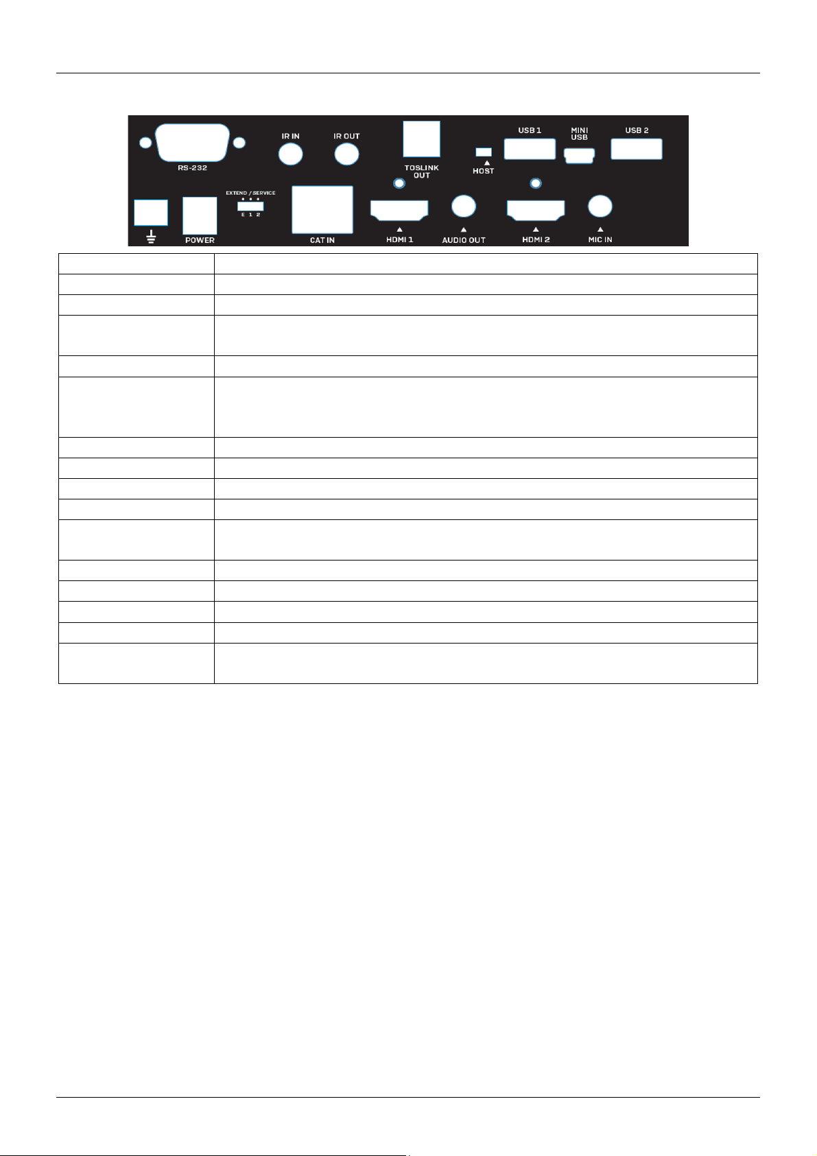
RS-232
Connessione per il sistema di controllo seriale
IR IN
Connessione per il ricevitore IR.
IR OUT
Connessione per il trasmettitore IR.
TOSLINK OUT
Connessione per un cavo TOSLINK (ottico) ad un amplificatore o sistema di
HOST
Fate riferimento alla sezione “Installazione & Utilizzo” per maggiori dettagli
USB 1
Connessione per dispositivi USB. Nota: Quando lo switch “Host” è impostato in
questa porta fornirà unicamente alimentazione elettrica al
MINI USB
Da connettore al PC o Laptop.
USB 2
Connessione per dispositivi USB.
GROUND
Connessione messa a terra
POWER
Connessione per l’alimentatore 12VDC 1.5A multi-country in dotazione.
EXTEND / SERVICE
Selettore Extend / Service per il controllo seriale. Fate riferimento alla sezione
CAT IN
Connettore per il Link HDBaseT. Cavo Cat.6 o sup. lungo max 100m (328.08ft).
HDMI 1
Connettore canale video 2 per cavi HDMI da collegare allo schermo/proiettore.
AUDIO OUT
Connettore Audio stereo da 3.5mm da collegare ad un amplificatore o casse
HDMI 2
Connettore canale video 2 per cavi HDMI da collegare allo schermo/proiettore.
MIC IN
Connettore Audio stereo da 3.5mm per segnale passante del microfono
Pannello posteriore:
diffusori attivo.
posizione “Host”
dispositivo USB connesso.
“Installazione & Utilizzo” per maggiori dettagli.
connesso.
Page 27

Manuale Italiano
Installazione & Utilizzo
Per l’installazione di questo extender vi preghiamo di seguire i passi elencati di seguito. Prima di iniziare
assicuratevi che tutti i dispositivi siano spenti. Questo esempio di installazione include due schermi ma se
intendete usare uno schermo singolo limitatevi a collegare un solo cavo HDMI alla sorgente.
Nota Bene: Prima di completare l’installazione vi raccomandiamo di controllare che tutti i prodotti siano
correttamente collegati a terra. Per il trasmettitore e il ricevitore il collegamento può essere fatto con i
morsetti di terra nell’angolo posteriore sinistro di entrambe le unità.
1. Utilizzando due cavi HDMI collegate le due porte HDMI in uscita dal PC/sorgente alle porte HDMI 1 e
2 del trasmettitore
2. Collegate il cavo Mini USB incluso alla porta corrispondente porta “Mini USB” del trasmettitore
inserendo poi il connettore USB Tipo A dall’altro capo del cavo in una porta USB del PC.
3. Se richiesto, per controllare il PC sorgente via seriale, connettere un cavo seriale DB9 standard alla
porta RS-232 del trasmettitore e poi a quella corrispondente sul PC
4. Per utilizzare la connessione audio passante, collegare il cavo TOSLINK (ottico) o quello stereo al PC
e alle porte “TOSLINK IN” o “AUDIO IN” del trasmettitore. Per aggiungere un microfono aggiungete un
cavo stereo da 3.5mm dalla porta “MIC OUT” del trasmettitore all’ingresso microfono del PC sorgente.
5. Collegate se richiesto il ricevitore o il trasmettitore IR rispettivamente alle porte alle porte “IR IN” o “IR
OUT” per la ripetizione dei segnali IR. Questo sistema funziona in entrambe le direzioni.
6. Collegate un capo del cavo (non incluso) Cat.6 (o superiore) alla porta “CAT OUT” del trasmettitore
7. Collegate l’altro capo del cavo Cat.6 alla porta “CAT IN” del ricevitore. Questo collegamento stabilirà
la connessione HDBaseT fra le due unità.
8. Utilizzando due cavi HDMI collegate le due porte HDMI del ricevitore ai due schermi utilizzati.
9. Per il controllo seriale collegate alla porta RS232 maschio del ricevitore un cavo seriale con cui
connettere dall’altro lato il dispositivo seriale da controllare.
10. Collegate se richiesto i dispositivi audio utilizzati con cavi adeguati alle porte TOSLINK (ottica) o 3.5mm
stereo.
11. Collegate un microfono, se richiesto, alla porta “MIC IN” del ricevitore.
12. Collegate le periferiche USB HID (mouse e tastiera), hub, stampanti, scanner, ecc. al ricevitore usando
le porte USB Tipo disponibili sull’unità.
13. Collegate gli alimentatori multi-country da 12VDC 1.5A alle prese di corrente e alle porte POWER sulle
unità trasmittente e ricevente
14. Accendete gli schermi ed infine il dispositivo sorgente.
Pulsante EDID
Per copiare l’EDID da uno o due schermi premete il tasto EDID sul pannello frontale dell’unità ricevente o
di quella trasmittente per 3 secondi. Il LED status comincerà a lampeggiare a colori alternati. L’EDID sarà
stato a questo punto copiato con successo.
Per abilitare l’EDID passante premete il tasto EDID sull’unità trasmittente o su quella ricevente per almeno
6 secondi. Questa azione cancellerà l’EDID copiato in precedenza.
Selettore Host
Il selettore Host viene utilizzato per determinare da dove il PC viene controllato. Per controllare il PC dalla
consolle remota (Quella dell’unità ricevente) assicuratevi che lo switch sia impostato su “Host” sull’unità
ricevente e dall’altro lato su quella trasmittente e vice versa. Assicuratevi sempre che i selettori non si
trovino mai entrambi dallo stesso lato . Dopo aver modificato le impostazioni dello switch è necessario
riavviare le unità dell’extender rimuovendo e ripristinando l’alimentazione da entrambi i lati.
Extend / Service Switch
Page 28
Manuale Italiano
Lo switch Extend / Service abilita l’estensione del segnale seriale. Vi preghiamo di lasciare entrambi i
selettori su “E”. Le altre posizioni (1 e 2) sono destinate ad eventuali aggiornamenti futuri del firmware.
LED Status
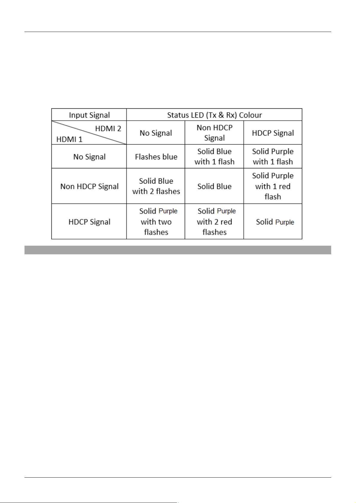
Il LED status su trasmettitore e ricevitore si illumina in base al tipo di trasmissione che viene stabilita fra
rle due unità. Quando nessuna connesione è presente il LED sul trasmettitore si illuminerà fisso in verde
mentre quello sul ricevitore sempre fisso ma in rosso. Fate riferimento alla seguente tabella per tutti gli
stati segnalati dai due LED status delle due unità trasmittente (TX) e riceve:
Risoluzione dei problemi
Dopo aver letto con attenzione la sezione Installazione & Utilizzo di questo manuale, se riscontrate
problemi di funzionamento fate riferimento ai seguenti suggerimenti:
Problema: non compare nessuna immagine a schermo:
Controllate che tutte le connessioni fra i vari componenti siano salde e siano state utilizzate le porte
corrette.
Controllate che i connettori di alimentazione DC siano fermamente inseriti nelle rispettive porte e che
i LED siano illuminati.
Spegnete tutti i dispositivi e poi riaccendeteli in quest’ordine: trasmettitore, ricevitore, gli schermi e la
sorgente.
Alcuni schermi possono aver problemi nella fase di inizializzazione. Disconnettete il cavo HDMI dallo
schermo e poi riconnettetelo.
Controllate che la lunghezza dei cavi HDMI utilizzati fra il trasmettitore e la sorgente e fra il ricevitore
e gli schermi non superi quella specificata nelle specifiche del prodotto. In questo caso utilizzate cavi
più corti rispettando le limitazioni indicate.
Riducete la lunghezza del cavo Cat.6 utilizzato o scegliete un cavo di qualità superiore
Problema: i dispositivi USB non funzionano:
Assicuratevi che i selettori Host siano impostati su “Host” sul ricevitore e dall’altro lato sul trasmettitore.
Controllate la connessione fra le porte USB sul trasmettitore e il PC sorgente sia solida.
Controllate che non ci siano dispositivi USB connessi ad un’unità inattiva.
Provate a collegare un’altra periferica USB (potrebbero esserci incompatibilità utilizzando periferiche
asincrone)
Provate a riavviare le unità dell’extender
Page 29

CE/FCC Statement
CE Certification
LINDY declares that this equipment complies with the European CE requirements relating to EMC and
RoHS.
CE Konformitätserklärung
LINDY erklärt, dass dieses Equipment den europäischen CE-Anforderungen in Bezug auf EMV und RoHS
entspricht.
FCC Certification
This equipment has been tested and found to comply with the limits for a Class B digital device, pursuant
to part 15 of the FCC Rules. These limits are designed to provide reasonable protection against harmful
interference in a residential installation.
You are cautioned that changes or modification not expressly approved by the party responsible for
compliance could void your authority to operate the equipment.
This device complies with part 15 of the FCC Rules.
Operation is subject to the following two conditions:
1. This device may not cause harmful interference, and
2. This device must accept any interference received, including interference that may cause undesired
operation.
This equipment has passed UL’s Safety test requirement, conforming to UL standard 60950-1 & 60065.
LINDY Herstellergarantie – Hinweis für Kunden in Deutschland
LINDY gewährt für dieses Produkt über die gesetzliche Regelung in Deutschland hinaus eine zweijährige Herstellergarantie ab Kaufdatum. Die detaillierten Bedingungen dieser Garantie finden Sie auf der LINDY Website aufgelistet
bei den AGBs.
Hersteller / Manufacturer (EU):.
LINDY-Elektronik GmbH LINDY Electronics Ltd
Markircher Str. 20 Sadler Forster Way
68229 Mannheim Stockton-on-Tees, TS17 9JY
Germany England
Email: [email protected] , T: +49 (0)621 470050 [email protected] , T: +44 (0)1642 754000
Page 30
Recycling Information
Tested to
FCC Standards
For Home and Office Use!
WEEE (Waste of Electrical and Electronic Equipment),
Recycling of Electronic Products
Europe, United Kingdom
In 2006 the European Union introduced regulations (WEEE) for the collection and recycling of all waste electrical
and electronic equipment. It is no longer allowable to simply throw away electrical and electronic equipment. Instead,
these products must enter the recycling process.
Each individual EU member state has implemented the WEEE regulations into national law in slightly different ways.
Please follow your national law when you want to dispose of any electrical or electronic products. More details can
be obtained from your national WEEE recycling agency.
Germany / Deutschland Rücknahme Elektroschrott und Batterie-Entsorgung
Die Europäische Union hat mit der WEEE Direktive Regelungen für die Verschrottung und das Recycling von Elektround Elektronikprodukten geschaffen. Diese wurden im Elektro- und Elektronikgerätegesetz – ElektroG in deutsches
Recht umgesetzt. Das Entsorgen von Elektro- und Elektronikgeräten über die Hausmülltonne ist verboten! Diese
Geräte müssen den Sammel- und Rückgabesystemen zugeführt werden! Dort werden sie kostenlos entgegen
genommen. Die Kosten für den weiteren Recyclingprozess übernehmen die Gerätehersteller.
LINDY bietet deutschen Endverbrauchern ein kostenloses Rücknahmesystem an, beachten Sie bitte, dass Batterien
und Akkus den Produkten vor der Rückgabe an das Rücknahmesystem entnommen werden müssen und über die
Sammel- und Rückgabesysteme für Batterien separat entsorgt werden müssen. Ausführliche Informationen zu
diesen Themen finden Sie stets aktuell auf der LINDY Webseite im Fußbereich.
France
En 2006, l'union Européenne a introduit la nouvelle réglementation (DEEE) pour le recyclage de tout équipement
électrique et électronique.
Chaque Etat membre de l’ Union Européenne a mis en application la nouvelle réglementation DEEE de manières
légèrement différentes. Veuillez suivre le décret d’application correspondant à l’élimination des déchets électriques
ou électroniques de votre pays.
Italy
Nel 2006 l’unione europea ha introdotto regolamentazioni (WEEE) per la raccolta e il riciclo di apparecchi elettrici ed
elettronici. Non è più consentito semplicemente gettare queste apparecchiature, devono essere riciclate. Ogni stato
membro dell’ EU ha tramutato le direttive WEEE in leggi statali in varie misure. Fare riferimento alle leggi del proprio
Stato quando si dispone di un apparecchio elettrico o elettronico.
Per ulteriori dettagli fare riferimento alla direttiva WEEE sul riciclaggio del proprio Stato.
No. 39374
1st Edition, May 2020
comply with
lindy.com
 Loading...