

Page 1
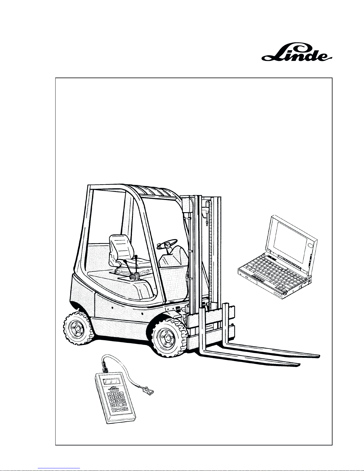
Service Training
This training material is only provided for your use and remains the exclusive property of
LINDE AG Werksgruppe Flurförderzeuge und Hydraulik
H01 / Chapter 1
350 804 4701.0400
Linde IC Engined T ruck
H 12/16/18/20 D-03/T -03
Series 350
with Linde Hydraulic Control (LHC)
Page 2

Page 3

Table of content
Page 1
Service T raining
H01 / Chapter 1
350 804 4701.0400
IC-ENGINED TRUCKS H 12/16/18/20 D-03/T-03, SERIES 350
1 Diesel engine 1
1.1 Engine specifications 1
1.2 Crankshaft 2
1.2.1 Adjusting alternator V-belt tension 2
1.2.2 Removing toothed belt 2
1.3 Fuel injection pump 5
1.3.1 Removal and installation of the fuel injection pump 5
1.3.2 Removing and installing the crankshaft sprocket 7
1.3.3 Check and adjust static injection pump timing 8
1.3.4 Checking engine timing 9
1.3.5 Stop leaks from the adapter of the injection pump 10
1.3.6 Adjust the idling speed and the governed speed (without load) 10
1.4 Fuel injectors 11
1.4.1 Remove and install fuel injectors 11
1.4.2 Servicing fuel injectors 12
1.4.3 Fuel injector parts 12
1.4.4 Check injector needle tip (visual check) 12
1.4.5 Check of fuel pressure 13
1.4.6 Check for leakages 13
1.5 Cylinder head 14
1.5.1 Cylinder head removal 14
1.5.2 Check cylinder head for distortion 14
1.5.3 Markings of cylinder head gaskets 14
1.5.4 Check piston at TDC 15
1.5.5 Fitting the cylinder head 15
1.5.6 Check compression pressure 17
1.5.7 Check hydraulic tappets 18
1.6 Glow plug system 19
1.6.1 Checking the glow plugs 19
1.6.2 Check the glow plugs 19
1.6.3 Glow plugs with burnt electrodes 20
2 Transmission 1
2.1 Digital electric-hydraulic control (LHC) 1
2.1.1 General 1
Page 4

Service T raining
Table of content
Page 2
H01 / Chapter 1
350 804 4701.0201
02.01
2.1.2 Electronic control of truck speed 2
2.2 Schematic diagram of the drive unit 4
2.3 Technical data of the travel drive system 5
2.4 Hydraulic circuit diagram 7
2.5 View of the variable pump 11
2.6 Cross sectional view of drive pump 12
2.7 Electric-hydraulic adjustment 13
2.7.1 Hydraulic adjustment with electronic control 15
2.7.2 Electric-hydraulic control 16
2.7.2.1 Begin of pump control 17
2.7.2.2 Swash angle of variable pump 17
2.7.2.3 Hydraulic zero position 17
2.7.2.4 Hydraulic brake valve 18
2.8 Towing device 19
2.9 Drive axle AH 20 -01 with wheel drive, multiple disc brake and hydraulic motor 20
2.9.1 Repairing the reduction gear, multiple disc brake and hydraulic motor 22
2.9.2 Renewing the radial sealing ring of the planetary gear 23
2.9.3 Removing and installing the multiple disc brake and hydraulic motor with
swashplate 02.01 26
2.10 Truck diagnostics and troubleshooting 30
2.10.1 Electrical system diagnostics 30
2.10.1.1 Working with the Linde Test Module 31
2.10.1.2 Diagnostics with a PC and the Linde Interface Converter 32
2.10.1.2.1 Linde Interface Converter 33
2.10.1.2.2 Installation of the Diagnostic software “Test & Setup” 33
2.10.1.2.3 Selecting the Linde Program 34
2.10.1.2.4 Starting the Diagnostic Program “Test & Setup” 02.01 35
2.10.1.3 Linde Diagnostic Program 02.01 36
2.10.1.3.1 Help Function 38
2.10.1.3.2 Overview of menu windows - LHC Software version 1.1 - 1.3 02.01 41
2.10.1.3.3 Menu windows in detail - LHC Software version 1.1 - 1.3 02.01 42
2.10.1.3.4 Overview of menu windows - LHC Software version 1.4 and 1.5 02.01 62
2.10.1.3.5 Menu windows in detail - LHC Software version 1.4 and 1.5 02.01 63
2.10.1.3.6 Overview of menu windows - LHC Software version 1.6 02.01 97
2.10.1.3.7 Menu windows in detail - LHC Software version 1.6 02.01 98
2.10.2 Hydraulic system diagnostics 131
2.10.2.1 Circuit diagram and overview for diagnostics 131
Page 5

Table of content
Page 3
Service T raining
H01 / Chapter 1
350 804 4701.0201
02.01
2.10.2.2 Test aids 133
2.10.2.2.1 Explanations to troubleshooting 133
2.10.2.3 Power-assisted steering 135
2.10.2.3.1 Troubleshooting without measurement of boost and maximum pressure 135
2.10.2.3.2 Troubleshooting with measurement of boost and maximum pressure 135
2.10.2.4 Hydraulic brake system 137
2.10.2.4.1 Functional test 137
2.10.2.4.2 Troubleshooting 137
2.10.2.5 Hydrostatic travel drive 140
2.10.2.5.1 Troubleshooting 140
4 Steering system 1
4.1 Schematic diagram of the steering system 1
5 Controls 1
5.1 Pedal stroke adjustment instructions 2
5.2 Adjustment instructions for the speed control 4
5.3 Engine speed sensor adjustment instructions 6
6 Electrical system 1
6.1 Basic diagram Diesel version 02.01 1
6.2 Basic diagram LPG version 02.01 7
6.3 Diagram for optional equipment 13
6.4 Layout of electrical installation 21
6.5 Composite instrument 22
7 Hydraulic system 1
7.1 Schematic 1
7.2 Sealing of the control valve 2
7.3 Setting of the pressure-limiting valve 3
9 LPG model of IC-engined fork truck H 12/16/18/20 T-03, series 350 1
9.1 Engine 1
9.1.1 Engine specifications 02.01 1
9.1.2 Toothed belt 2
9.1.2.1 Overall view of toothed belt guard 2
9.1.2.2 Removing, installing, tensioning the toothed belt 3
Page 6

Service T raining
Table of content
Page 4
H01 / Chapter 1
350 804 4701.0201
02.01
9.1.2.3 Adjusting the alternator V-belt tension 5
9.1.3 Cylinder head 6
9.1.3.1 Removing and installing the cylinder head 6
9.2 Electrical system 10
9.2.1 Electronic ignition 10
9.2.1.1 TSZ-H ignition system (transistorised ignition system) 11
9.2.1.2 Safety measures for TSZ-Hall system 12
9.2.1.3 Installation of distributor 12
9.2.1.4 Checking and adjusting the ignition timing 14
9.2.1.5 Checking the TSZ-H ignition system 15
9.2.1.5.1 Switch unit A1 16
9.2.1.5.2 Hall generator 18
9.3 LPG installation 20
9.3.1 Schematic 20
9.3.2 LPG mixer 21
Index 02.01
Page 7
Section 1
Page 1
Service Training
H01 / Chapter 1
350 804 4701.0400
1 DIESEL ENGINE
1.1 ENGINE SPECIFICATIONS
Engine Type VW ADG
Capacity 1896 cm
3
Output 27 kW at 2200 rpm
Injection Pressure 130
+8
bar
Point of Injection 1.00 ± 0.02 mm stroke
Compression Ratio 23 : 1
Compression Specified Value: 34.0 bar
Wear Limit: 26.0 bar
Max. Permissible Pressure Difference 5 bar
Lower Idling Speed 1030
+ 30
rpm
Upper Idling Speed 2350 rpm
Rated Speed 2200 rpm
Valve Clearance Hydraulic Valve Timing Balance
Firing Order 1 - 3 - 4 - 2
Minimum Oil Pressure at Top Idling Speed
and Oil Temperature approx. 80 °C 2 bar
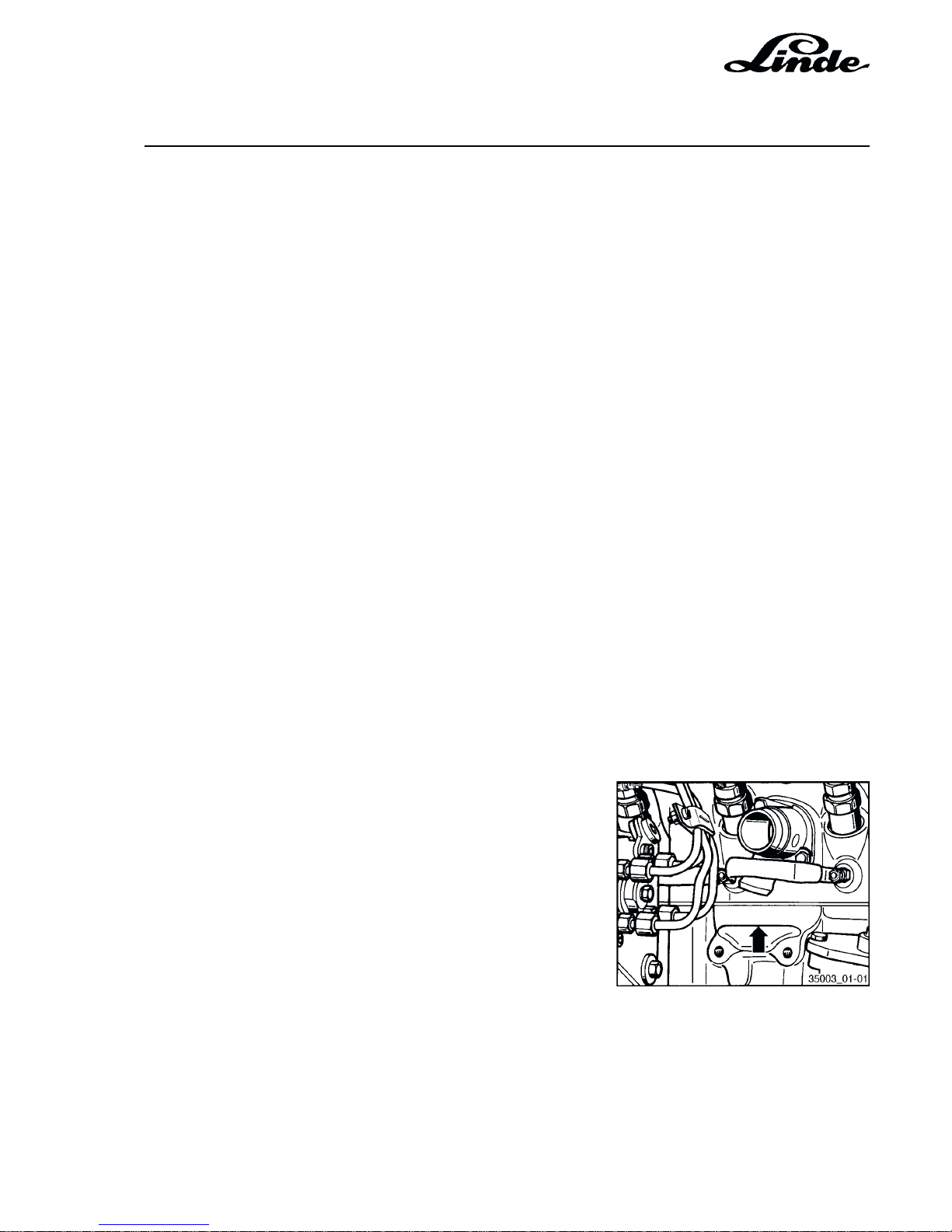
The engine number is stamped on the cylinder block
between the injection pump and the vacuum pump.
The engine number is always shown on the vehicle data
plate on the toothed belt cover.
Page 8
Service Training
Section 1
Page 2
H01 / Chapter 1
350 804 4701.0400
1.2 CRANKSHAFT
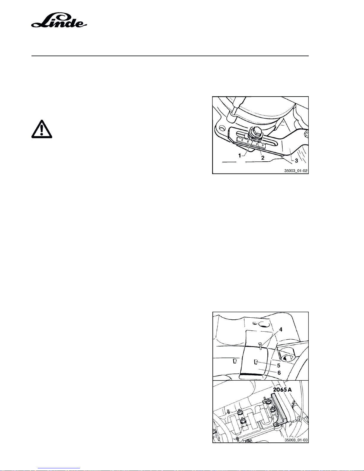
1.2.1 ADJUSTING ALTERNATOR V-BELT TENSION
- Loosen all security bolts (1) for tensioner (3) and alternator by at least one turn.
ATTENTION
The alternator must be easily moveable by hand.
- Tension V-belt by tensioning nut (2) with a torque wrench.
Specification:
New V-belt: 8 Nm
Used V-belt: 4 Nm
and tighten tensioning nut securing bolt to 30 Nm.
- Tighten all tensioner and alternator securing bolts.
NOTE: Adjustment is ideally carried out with the torque
wrench V.A.G. 1410 in connection with the
socket spanner V.A.G. 1410/2.
1.2.2 REMOVING TOOTHED BELT
REMOVAL
- Remove upper belt guard and cylinder head cover.
- Turn crankshaft to TDC on No. 1 cylinder.
The TDC mark (5) on the flywheel (6) must be in line with
the boss (4) on the bell housing.
- Fix camshaft in position with setting bar (2065 A).
- Align setting bar as follows:
Turn camshaft until one end of bar touches the cylinder
head. Measure the gap at the other end of the setting bar
with the feeler. Take half of gap measurement and insert
feeler of this thickness between setting bar and cylinder
head. Now turn the camshaft so that the setting bar
touches the feeler. Insert second feeler of the same
thickness between the other end of the setting bar and the
cylinder head.
Page 9
Section 1
Page 3
Service Training
H01 / Chapter 1
350 804 4701.0400
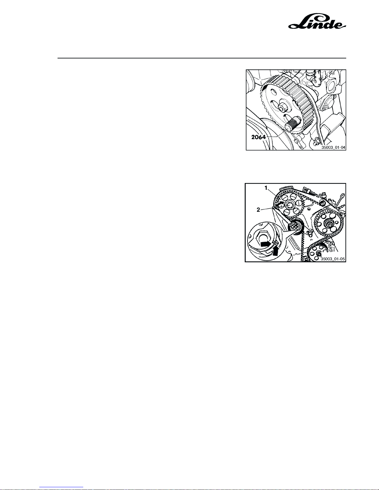
- Hold injection pump sprocket in position with drift (2064).
- Loosen tensioner.
- Remove pulley for coolant pump.
- Remove lower toothed belt guard.
- Remove belt guard.
INSTALLATION
- Check and ensure TDC mark on flywheel is aligned with
reference mark.
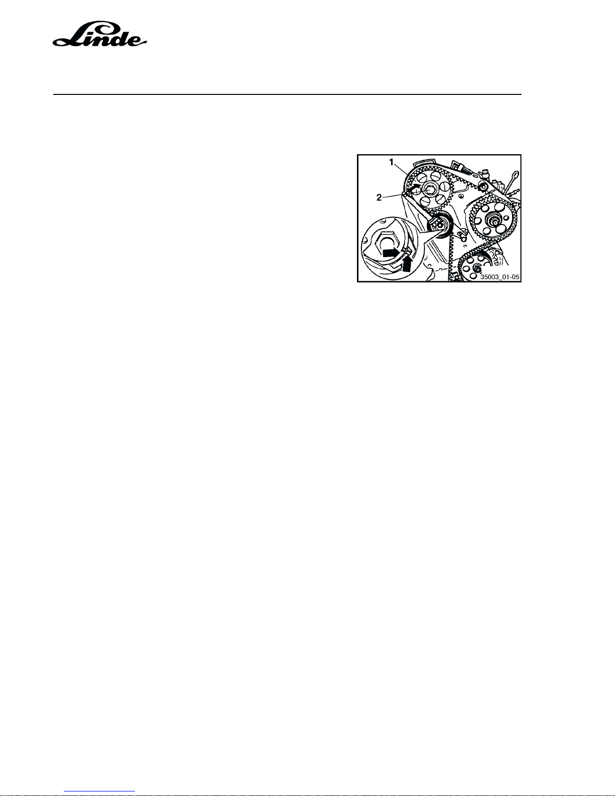
- Loosen camshaft sprocket bolt (2) by half a turn. Free
sprocket (1) on taper by tapping with hammer (using a
drift through the hole in the rear toothed belt guard).
- Fit toothed belt and remove pin from injection pump
sprocket.
- Install the idling pulley. Torque loading: 25 Nm.
- Turn the tensioning pulley clockwise with a spanner (eg Matra
V159) until the notch and boss (arrows) are in line.
- Tighten the clamping nut at the tensioning pulley. Torque
loading: 20 Nm.
- Recheck if the TDC mark on the flywheel and the reference
mark are in line.
- Tighten fastening screw of valve timing sprocket to 45 Nm.
- Remove the setting bar.
- Turn the crankshaft by two turns in normal direction and
check that the tension of the toothed belt is in accordance
with the specification.
- Install V-belt, toothed belt guard and cylinder head cover.
- Check the point of injection of the injection pump.
Page 10
Service Training
Section 1
Page 4
H01 / Chapter 1
350 804 4701.0400
CHECKING THE SEMIAUTOMATIC TENSIONING PULLEY
TEST CONDITION
- Toothed belt installed and tensioned
TEST PROCEDURE
- Push down on the toothed belt with the thumb. The notch and
boss -arrow- should go out of line.
- Release the pressure on the toothed belt. The tensioning pulley
should return to its initial position. (Notch and boss are in line
again.)
Page 11
Section 1
Page 5
Service Training
H01 / Chapter 1
350 804 4701.0400
1.3 FUEL INJECTION PUMP
1.3.1 REMOVAL AND INSTALLATION OF THE FUEL INJECTION PUMP
NOTE: In case a defect is noted on the fuel injection
pump the fuel injection pump has to be exchanged since to repair it a fuel injection test bed is
necessary.
REMOVAL
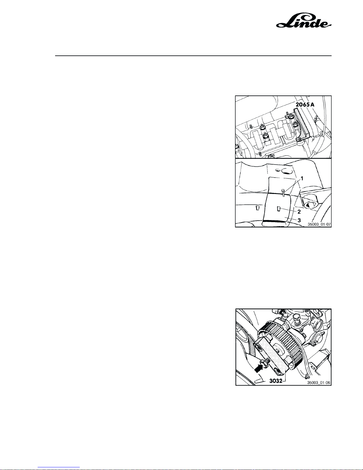
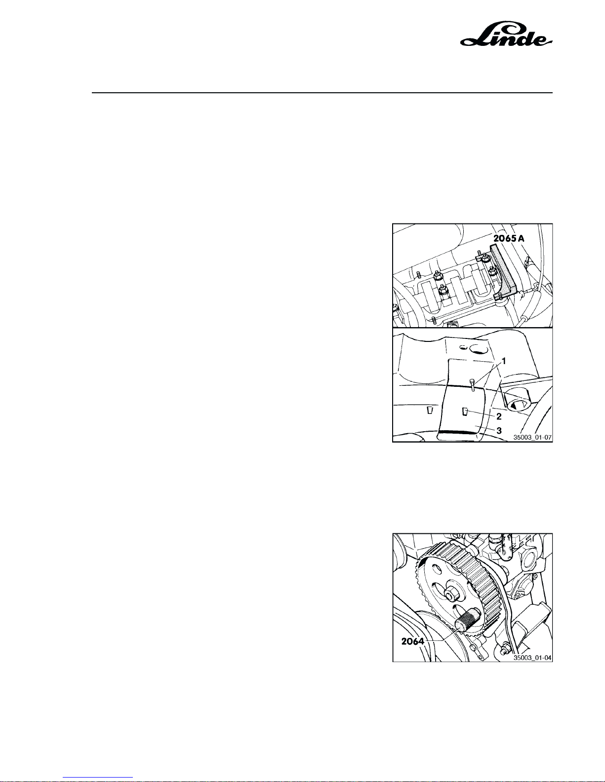
- Turn crankshaft to TDC on No. 1 cylinder. The TDC mark
(2) on the flywheel (3) must be in line with the boss (1)
on the bell housing. Fix camshaft with setting bar (2065
A). Align setting bar as follows:
Turn camshaft until one end of the setting bar touches the
cylinder head. Measure the gap at the other end of the
setting bar with the feeler gauge. Insert the feeler gauge
with one half of the thickness between the setting bar and
the cylinder head. Turn the camshaft now so that the
setting bar rests on the feeler gauge. Insert a second
feeler gauge with the same thickness at the other end
between the setting bar and the cylinder head.
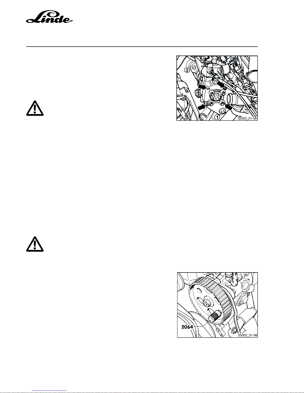
- Remove toothed belt from camshaft and injection pump
gears.
- Loosen nut of the fuel injection gear.
- Loosen the puller legs and put on puller (3032).
- Align puller legs with holes in the fuel injection pump gear
and tighten.
- Put the injection pump gear under tension with the puller.
- Loosen the injection pump gear from the taper of the fuel
injection pump by tapping slightly on the puller spindle
(see arrow). (Hold fuel injection pump sprocket so that it
does not fall down).
- Detach all fuel pipes from the fuel injection pump and
cover the holes with a clean cloth.
NOTE: Use open ring spanner (3035) to loosen injec-
tion pipes.
Page 12
Service Training
Section 1
Page 6
H01 / Chapter 1
350 804 4701.0400
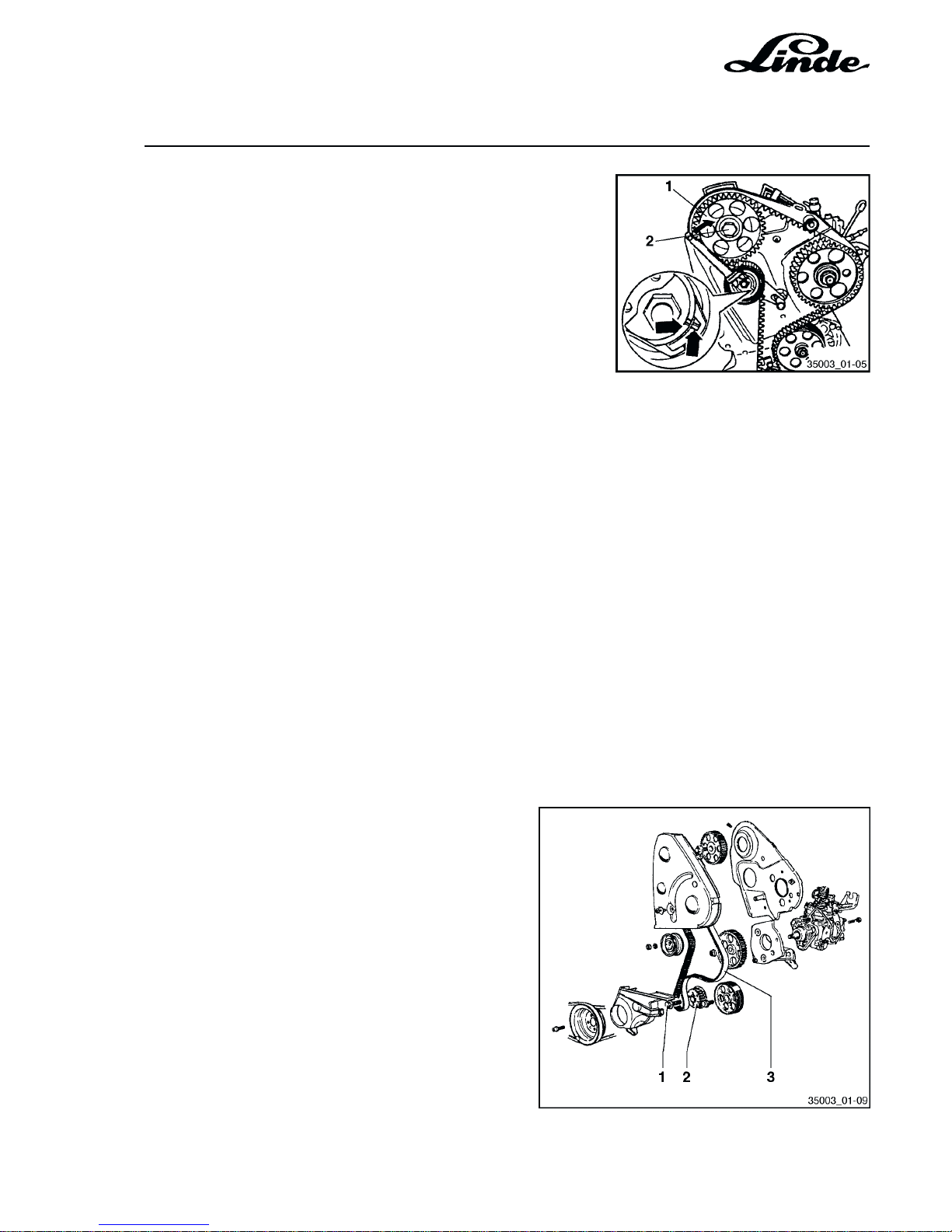
- Remove securing bolts (2) from bracket (3 bolts).
- Remove securing bolt (1) from rear support bracket.
NOTE: Loosen the lower and right-hand securing bolt
from the front.
ATTENTION
Under no circumstances should the securing
bolts (see arrows) holding the fuel injection pump
head be loosened.
Loosening the securing bolts would allow the
head to move and would cause the breakage of
the distributor plunger.
INSTALLATION
- Install the fuel injection pump and align centrally in the
elongated flange holes.
Tightening torques:
Pump mounting bolts: 25 Nm
Fuel pipes: 25 Nm
Injection pump sprocket: 45 Nm
ATTENTION
Do not interchange the feed and return pipe banjo
bolts. The inside diameter of the bolt for the return
pipe is smaller and the hexagon head is marked
"OUT".
- Install injection pump sprocket and fix position with
positioning pin (2064).
- Loosen bolt of camshaft sprocket by half a turn. Free
camshaft sprocket from the taper by tapping with a
hammer (using a drift through the hole in the rear toothed
belt guard).
- Check that TDC mark on the flywheel is aligned with the
reference mark
- Install toothed belt and remove the positioning pin from
the fuel injection pump sprocket.
Page 13
Section 1
Page 7
Service Training
H01 / Chapter 1
350 804 4701.0400
- Install the pulley. Torque loading: 25 Nm.
- Turn the tensioning pulley clockwise with a spanner (eg Matra
V159) until the notch and boss (arrows) are in line.
- Tighten the clamping nut at the tensioning pulley. Torque
loading: 20 Nm.
- Recheck if the TDC mark on the flywheel and the reference
mark are in line.
- Tighten the camshaft pulley fastening screw to 45 Nm.
- Remove the adjustment ruler.
- Rotate the crankshaft another two turns in the direction of
engine rotation and recheck the tension of the toothed belt.
- Check the operation of the tensioning pulley.
- Check the start of delivery.
- Check and adjust the idling speed and stall speed.
1.3.2 REMOVING AND INSTALLING THE CRANKSHAFT SPROCKET
Precondition:
- The toothed belt (3) is removed.
REMOVAL
- Remove the fastening screw (1).
- Take the sprocket (2) off the crankshaft.
INSTALLATION
- Slide the sprocket (2) onto the crankshaft.
- Use a new fastening screw (1).
- Oil the thread and head mating surface and install
the screw.
Tightening procedure: 90 Nm + 90°
Page 14
Service Training
Section 1
Page 8
H01 / Chapter 1
350 804 4701.0400
1.3.3 CHECK AND ADJUST STATIC INJECTION PUMP TIMING
CHECK AND ADJUSTMENT CONDITIONS
Toothed belt tension OK.
Operating lever of fuel injection pump on stop.
Set engine to TDC on No. 1 cylinder.
Engine installed:
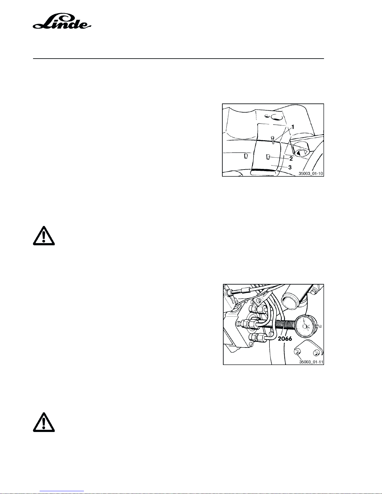
- Turn the crankshaft until TDC mark (2) on the flywheel (3)
is in line with the boss (1) on the bell housing.
CHECKING AND ADJUSTING
- Unscrew plug from fuel injection pump head.
ATTENTION
Always fit a new washer when installing the plug.
Tightening torque 15 Nm. If leaks occur the plug
can be tightened to a maximum torque of 25 Nm.
- Install adaptor (2066) and small dial gauge (measuring
range 0 ... 3.0 mm) in place of the plug and preload the
dial gauge to about 2.5 mm.
- Turn the crankshaft slowly anticlockwise (opposite to
normal rotation) until the dial gauge needle does not
move any more.
- Adjust the dial gauge with approx. 1 mm preload to "0".
- Turn the crankshaft clockwise (normal rotation) until the
TDC mark on the flywheel is aligned with the reference
mark.
- Read the point of injection from the dial gauge.
Test figure = 0.93 ... 1.07 mm stroke
Setting figure = 1.00 ± 0.02 mm stroke
ATTENTION
In case the value is within the specified tolerance
an adjustment is not required.
- To adjust loosen the three screws on the bracket and the
screw holding the rear support.
Page 15
Section 1
Page 9
Service Training
H01 / Chapter 1
350 804 4701.0400
- Adjust the point of injection by turning the fuel injection pump
to give the setting value.
- Tighten the bolts to 25 Nm.
1.3.4 CHECKING ENGINE TIMING
- Remove cylinder head cover.
- Check the tension of the toothed belt.
- Set the engine to TDC on the cylinder No. 1.
The setting bar (2065A) must fit into the slot on the camshaft.
If the setting bar cannot be inserted adjust the valve timing
as follows:
- Turn the crankshaft so that the setting bar can be inserted and
align the setting bar as follows:
Turn the camshaft so that one end of the setting bar touches
the cylinder head. Measure the gap at the other end of the
setting bar with a feeler gauge. Insert a feeler gauge with one
half of the measurement between the setting bar and the
cylinder head. Now turn the camshaft so that the setting bar
touches the feeler gauge. Insert a second feeler gauge with
the same measurement at the other end between the setting
bar and the cylinder head.
- Loosen bolt of the valve timing sprocket by half a turn. Free
the sprocket from taper by inserting a drift through the hole
in the rear toothed belt guard and by striking the drift with a
hammer.
- Fix injection pump sprocket with the fixing pin (2064).
- Check TDC position; if necessary turn the crankshaft until
TDC mark (2) on the flywheel (3) is aligned with the boss (1)
on the bell housing.
NOTE: To adjust the injection pump sprocket and the
TDC mark on the flywheel it may be necessary to
remove the toothed belt.
- Remove fixing pin.
- Tension the toothed belt and tighten the bolt of the valve
timing sprocket to 45 Nm.
- Remove the setting bar.
- Check the timing of the injection pump.
Page 16
Service Training
Section 1
Page 10
H01 / Chapter 1
350 804 4701.0400
1.3.5 STOP LEAKS FROM THE ADAPTER OF THE INJECTION PUMP
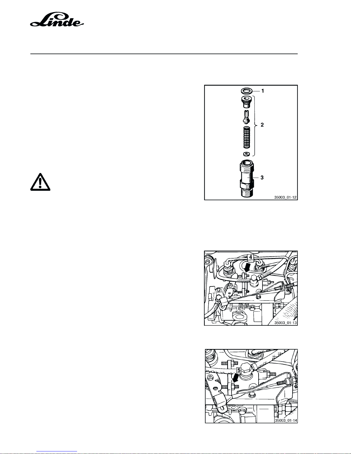
1 Sealing ring
2 Pressure valve
3 Adapter
- Loosen the injection pipe.
- Tighten the adapter to 45 Nm.
- Tighten the injector pipe to 25 Nm.
In case the leak is not being stopped install new adapter
and new washer.
ATTENTION
When replacing the new adapters do not
interchange the pressure valve.
1.3.6 ADJUST THE IDLING SPEED AND THE GOVERNED SPEED (WITHOUT LOAD)
Engine oil temperature minimum 60 °C.
The engine speed can be measured with the ignition tester
(V.A.G. 1367) using the TDC sender or the adapter (VW
1324).
ADJUST THE IDLING SPEED OR MIN. GOVERNED
SPEED (WITHOUT LOAD)
- Adjust the idling speed with the idling adjustment screw (4)
according to the engine specifications.
- Lock the adjusting screw.
ADJUST GOVERNED SPEED OR MAX. GOVERNED
SPEED (WITHOUT LOAD)
- Open the throttle fully and set the engine speed with the
adjustment screw (5) according to the engine
specifications.
- Lock the adjustment screw.
Page 17
Section 1
Page 11
Service Training
H01 / Chapter 1
350 804 4701.0400
1.4 FUEL INJECTORS
1.4.1 REMOVE AND INSTALL FUEL INJECTORS
NOTE: Defective fuel injectors cause the following
troubles:
- Misfiring
- Knocking in one or more cylinders
- Engine overheating
- Loss of power
- Excessively smoky black exhaust
- Increased fuel consumption
- Excessive blue smoke on cold start
Defective fuel injectors can be located by loosening the fuel
pipe unions on each fuel injector when the engine is running
at a fast idle. If the engine speed remains constant after
loosening a pipe union this denotes the faulty fuel injector.
REMOVAL
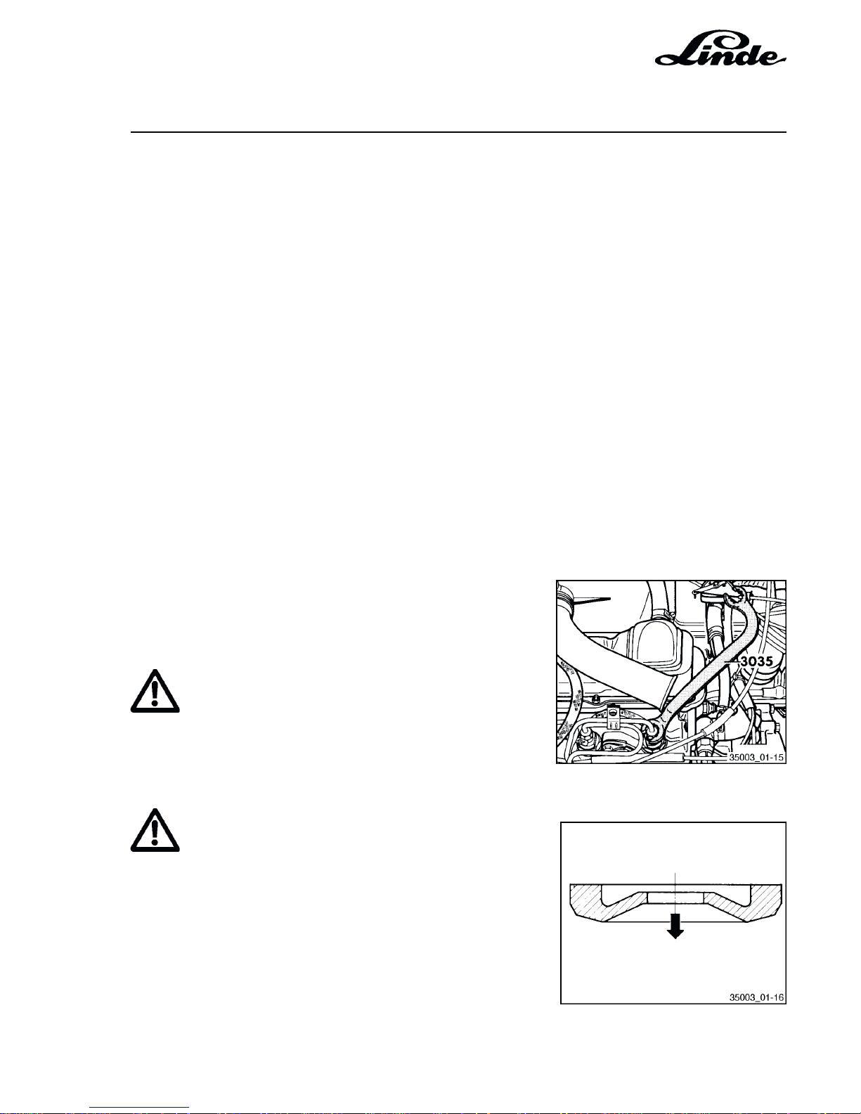
- Detach the injector pipes with the slotted ring spanner
(3035)
- Remove the fuel injectors with the SW27 socket.
ATTENTION
Always remove the fuel pipe set complete. Do not
alter the shape of the fuel pipes.
INSTALLATION
ATTENTION
Always fit new heat shields between the cylinder
head and the fuel injectors.
Fitting position of the heat shields: The arrow points
towards the cylinder head.
Tightening torques:
Fuel injector pipes: 25 Nm
Fuel injectors: 70 Nm
Page 18
Service Training
Section 1
Page 12
H01 / Chapter 1
350 804 4701.0400
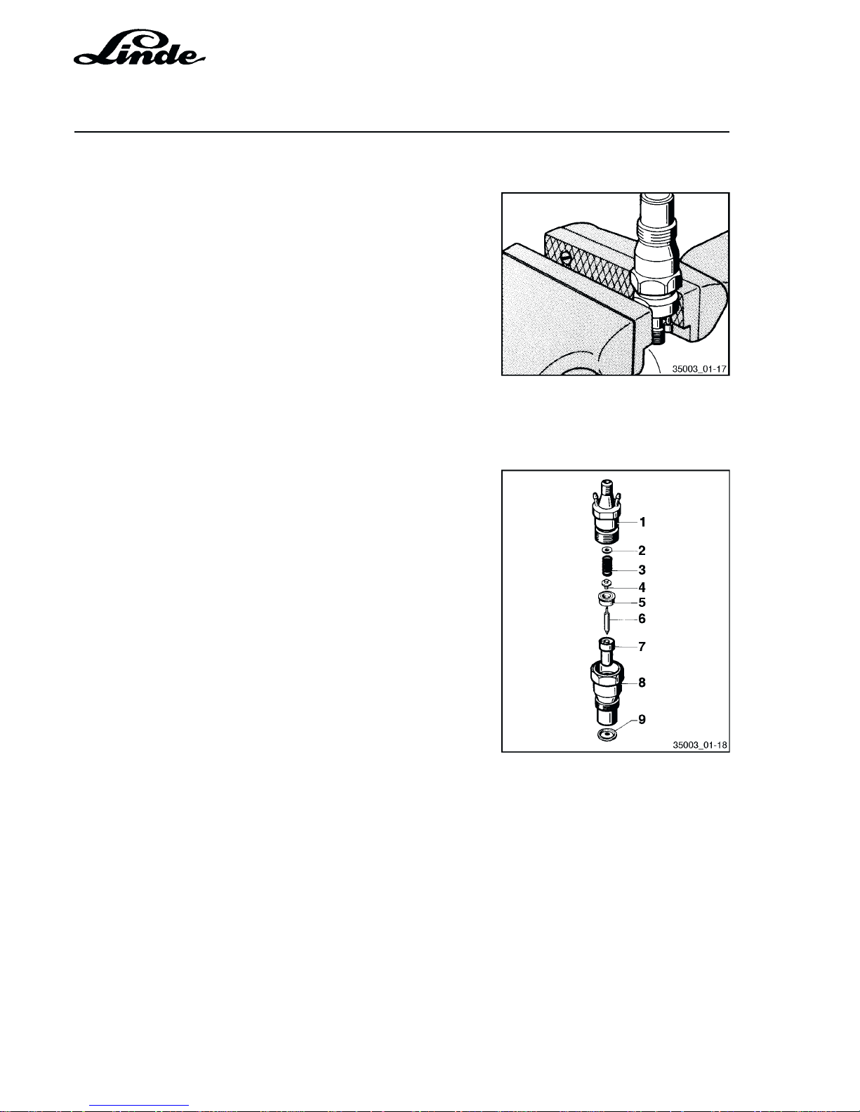
1.4.2 SERVICING FUEL INJECTORS
- Clamp the upper part of the fuel injector in vice and loosen
the hexagon.
- To prevent the parts from falling out clamp the lower part
in vice and dismantle injector. When dismantling the
injector keep all individual parts together and do not
interchange with parts from other injectors.
Tightening torque for the upper and the lower part of the fuel
injector: M = 70 Nm.
1.4.3 FUEL INJECTOR PARTS
1 Upper part of injector
2 Setting washer
3 Injector spring
4 Thrust pin
5 Nozzle holder insert
6 Injector needle
7 Nozzle body
8 Lower part of injector
9 Heat shield
1.4.4 CHECK INJECTOR NEEDLE TIP (VISUAL CHECK)
If the needle tip is broken off or bent replace fuel injector or
nozzle with needle.
Page 19
Section 1
Page 13
Service Training
H01 / Chapter 1
350 804 4701.0400
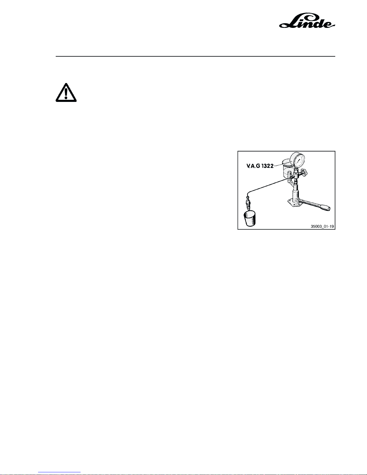
1.4.5 CHECK OF FUEL PRESSURE
ATTENTION
When testing the injectors take care not to expose
the hands to the injector spray as the high pressure
will cause the fuel spray to penetrate the skin and
cause severe injuries.
Gauge valve open:
- Move pump lever down slowly. When injecting read the
injection pressure from the gauge and adjust if necessary
by changing the setting washer.
Specified pressure value:
New injectors: 130 ... 138 bar
Wear limit: 120 bar
Thicker setting washer = increases the injection pressure
Thinner setting washer = decreases the injection pressure
Increasing the thickness of the setting washer by 0.05 mm
increases the injection pressure by approx. 5.0 bar.
Setting washers are available in thicknesses from
1.00 ... 1.95 mm in steps of 0.05 mm. The box 3065 should
be used to store the washers.
NOTE: When servicing used injectors set the injection
pressure to the value of new injectors.
1.4.6 CHECK FOR LEAKAGES
Gauge valve open:
- Press the pump lever down slowly and hold a pressure
of about 110 bar for 10 seconds. Then no fuel should leak
from the nozzle tip.
Page 20
Service Training
Section 1
Page 14
H01 / Chapter 1
350 804 4701.0400
1.5 CYLINDER HEAD
1.5.1 CYLINDER HEAD REMOVAL
NOTE: The cylinder head can be removed and installed with
the engine installed. If a replacement cylinder head
is installed with the camshaft mounted, the mating
surfaces of cup tappets and cams must be oiled after
installation of the head. The supplied plastic covers
for the protection of the open valves may only be
removed immediately before the installation of the
cylinder head. If the cylinder head is to be replaced,
the entire coolant must be drained. Check
compression pressure.
1.5.2 CHECK CYLINDER HEAD FOR DISTORTION
- max 0.1 mm
NOTE: It is not allowed to rework cylinder heads of
Diesel engines.
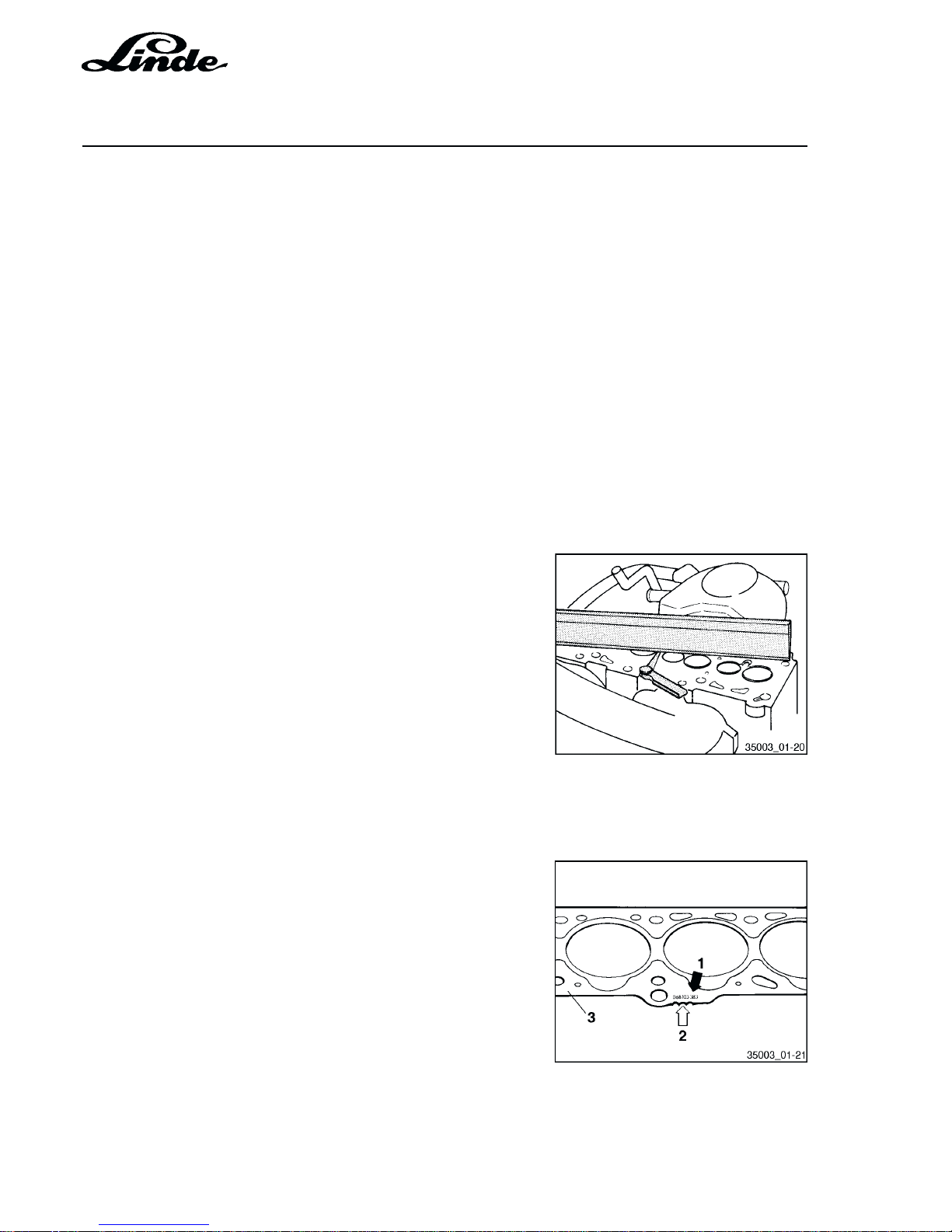
1.5.3 MARKINGS OF CYLINDER HEAD GASKETS
Spare part number = (1)
Notches/holes = (2)
Depending of the piston height cylinder head gaskets of
different thicknesses have to be installed. When replacing
the cylinder head gasket install new gasket with the same
marks
Page 21
Section 1
Page 15
Service Training
H01 / Chapter 1
350 804 4701.0400
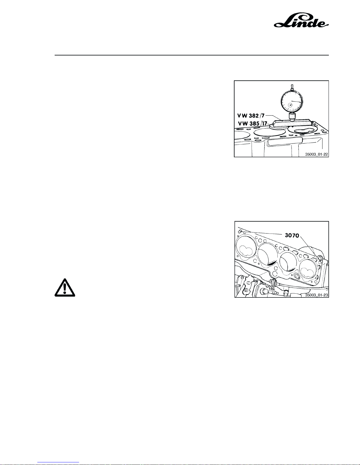
1.5.4 CHECK PISTON AT TDC
The piston height at TDC must be measured when fitting
new pistons or short engines. Depending on the piston
height the corresponding cylinder head gasket (3) has to
be fitted in line with the following table.
Piston height Identification
Notches/Holes
0.66 mm ... 0.86 mm 1
0.87 mm ... 0.90 mm 2
0.91 mm ... 1.02 mm 3
1.5.5 FITTING THE CYLINDER HEAD
NOTE: - Before installing the cylinder head cover,
turn the crankshaft to TDC.
- Then turn the crankshaft backwards until all
pistons are equally below TDC.
- After securing the cylinder head turn the
camshaft sprocket so that the cams for
cylinder No. 1 face upwards equally. Before
fitting the toothed belt turn the crankshaft
according to engine rotation to TDC.
ATTENTION
Always replace cylinder head bolts.
- Position the cylinder head gasket on the fitted pins.
- To centre screw the guide pins from guider (3070) into the
outer holes of the intake side.
- Fit the cylinder head and install the remaining 8 cylinder
head bolts and tighten by hand.
- Remove the guide pins using the tool from guider (3070)
and install the cylinder head bolts.
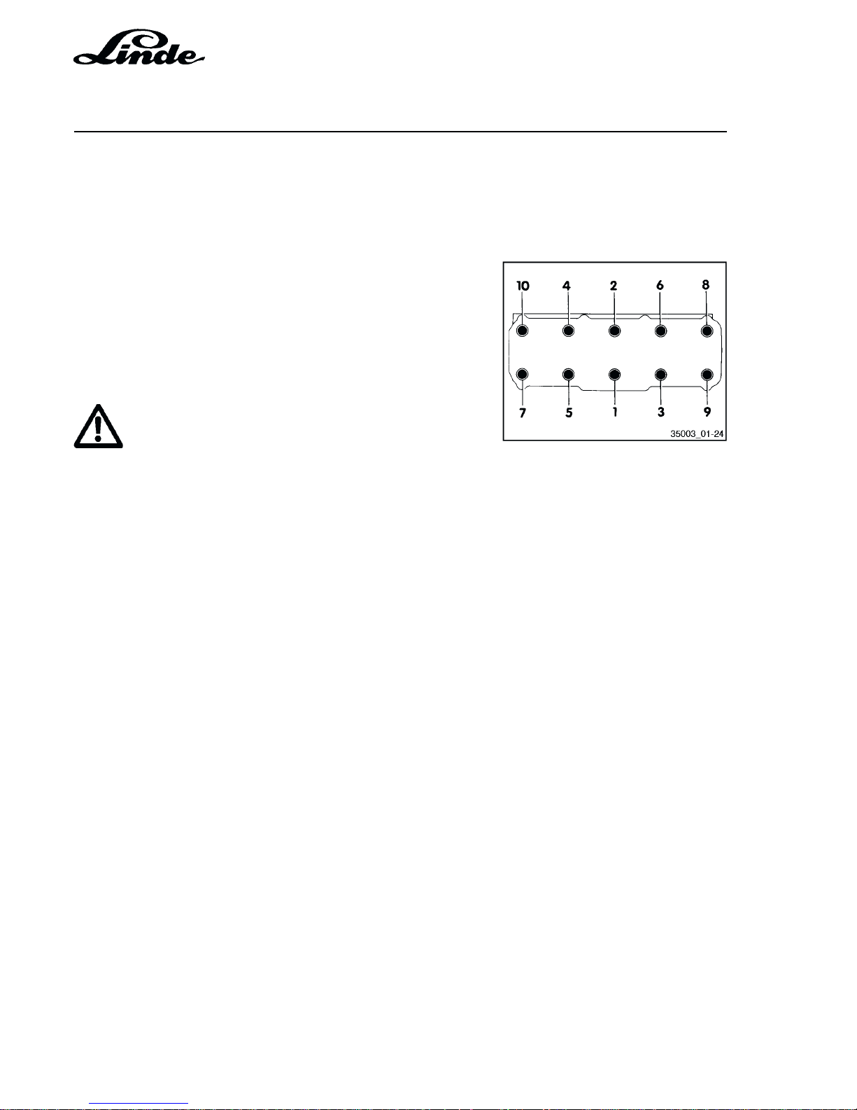
- Tighten the cylinder head bolts - when loosening them,
reverse the sequence.
- Tighten all cylinder head bolts one after the other in three
stages (when the engine is cold).
Page 22
Service Training
Section 1
Page 16
H01 / Chapter 1
350 804 4701.0400
Tightening torques:
Stage I = 40 Nm
Stage ll = 60 Nm
Stage lll = ½ turn (180 °)
without stopping further turn with normal spanner
(2 x 90 ° is also permissible).
- Run engine warm (oil temperature above 50 °C) and
tighten the securing bolts ¼ turn (90 °) with a normal
spanner in one movement and without loosening them
(watch sequence).
ATTENTION
There is no need to retighten the cylinder head bolts
after 10 hours engine running.
Page 23
Section 1
Page 17
Service Training
H01 / Chapter 1
350 804 4701.0400
1.5.6 CHECK COMPRESSION PRESSURE
Engine oil temperature min. 30 °C.
- Disconnect the wire from the stop control at the injection
pump and insulate it.
- Remove the injector pipes with slotted ring spanner
(3035).
- Remove all fuel injectors and remove the heat shields.
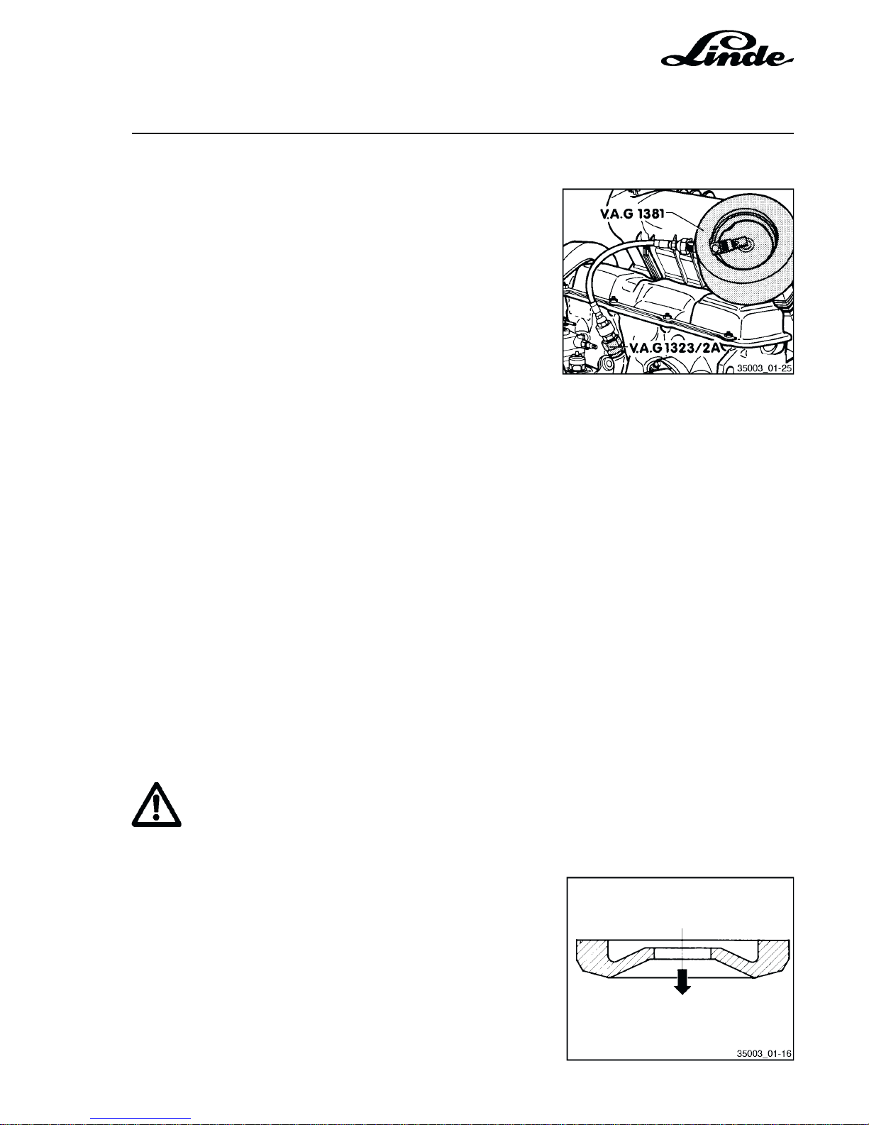
- Fit the adapter (V.A.G. 1381/2A) instead of the injectors.
Place the old heat shields between the adapter and the
cylinder head.
- Fit the compression pressure tester (V.A.G. 1381)
manually into the adapter.
NOTE: See use instructions for compression pressure
tester.
- Operate the starter motor until the compression pressure
tester does not show a further pressure increase.
Compression pressure for V.A.G. 1381 and VW 1323
(Gauge pressure)
Specified value: 34.0 bar
Wear limit: 26.0 bar
Max. permissible pressure limit: 5.0 bar
ATTENTION
Always fit new heat shields between the cylinder
head and the injectors.
- Fitting position for the heat shields: Arrow points to the
cylinder head
- Tightening torques:
Injector pipes = 25 Nm
Injectors = 70 Nm
Page 24
Service Training
Section 1
Page 18
H01 / Chapter 1
350 804 4701.0400
1.5.7 CHECK HYDRAULIC TAPPETS
NOTES: - Place the removed tappets with the cams-
haft contact surface on a clean surface.
- Replace tappets complete only (cannot be
adjusted or repaired).
- Irregular valve noises when starting the
engine are normal.
- Start the engine and run it until the radiator
fan has switched on once.
- Increase the engine speed to the max.
idling speed for 2 minutes. If the hydraulic
tappets are still noisy locate the defective
tappets as follows:
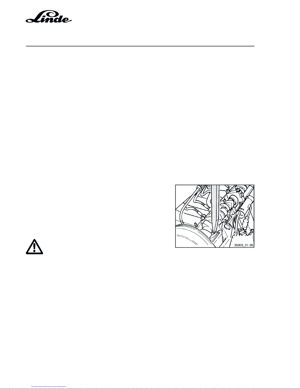
- Remove cylinder head cover.
- Turn the crankshaft until the cam of the
tappet to be checked is pointing upwards.
- Press the tappet down with a wooden or
plastic wedge. If a free travel is in excess
of 0.1 mm before the valve opens replace
the hydraulic tappet.
ATTENTION
When the new tappets have been installed the
engine must not be started for about 30 minutes
(the valves will strike the pistons).
Page 25

Section 1
Page 19
Service Training
H01 / Chapter 1
350 804 4701.0400
1.6 GLOW PLUG SYSTEM
1.6.1 CHECKING THE GLOW PLUGS
Test conditions:
Engine cold.
Battery voltage OK.
Voltage is present at the glow plugs.
- Connect the current supply to the test appliance
(V.A.G. 1315A)
- Place the glow plug wire in the current clamp.
- Press the button for the current measurement with the
clamp.
- Pull the wire off the engine temperature sender.
- Hold the ignition key in glow plug position for max.
15 seconds.
Current draw approx. 48 A, the glow plugs are OK. Current
draw below 48 A, see "check the glow plugs".
1.6.2 CHECK THE GLOW PLUGS
After stabilization on the rapid glow system the current
draw from the glow plugs is approx. 12 A per plug. If the glow
plugs show a current draw of abt.
36 A = one glow plug is defective
24 A = two glow plugs are defective
12 A = three glow plugs are defective
0 A = all glow plugs are defective
These values can only be achieved with a battery voltage
above 11.5 V.
- Remove the wire and the bus bar for the glow plugs.
- Attach the diode test lamp (V.A.G. 1572) to the battery
positive (+) and apply probe in turn to each glow plug.
Diode test lamp lights up: glow plug OK.
Diode test lamp does not
light up: replace the glow plug
(torque 25 Nm).
Page 26
Service Training
Section 1
Page 20
H01 / Chapter 1
350 804 4701.0400
NOTE: The glow plug tightening torque of 25 Nm must
not be exceeded otherwise the ring gap between the glow pin and the thread will be
squeezed together.
The glow plugs can fail prematurely due to this
situation.
If no defects are found but the engine is still hard to start the
glow plugs should be visually checked (injectors removed)
while glowing.
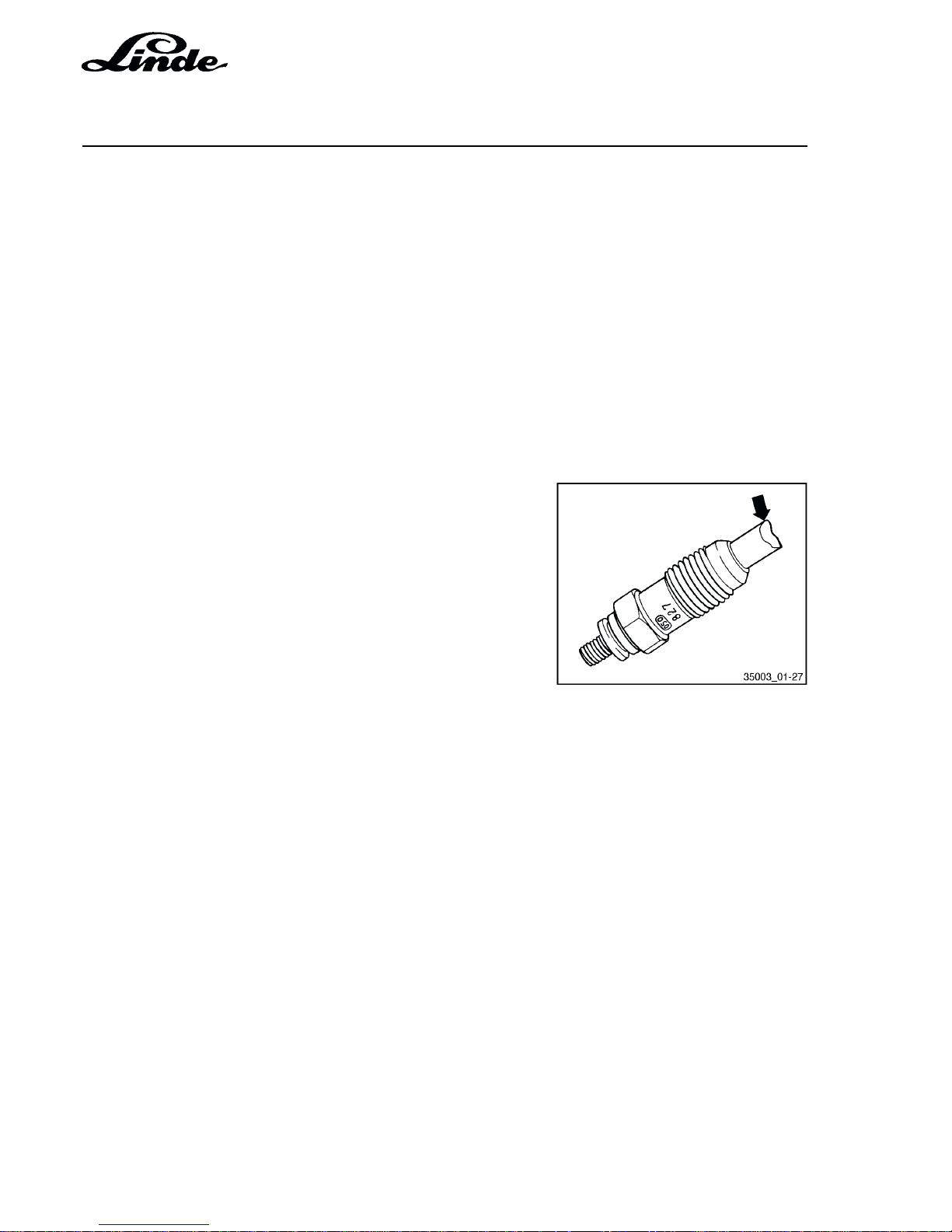
1.6.3 GLOW PLUGS WITH BURNT ELECTRODES
Burnt electrodes in glow plugs are very often caused by
faulty injectors Damages of this nature are not due to faults
in or on the glow plugs.
When a damage of this nature is found (see arrow) it is not
sufficient to merely replace the glow plug. The injectors
must also be checked for nozzle pressure and nozzle
leakages.
Page 27

Section 2
Page 1
Service Training
H01 / Chapter 1
350 804 4701.0400
2 TRANSMISSION
2.1 DIGITAL ELECTRIC-HYDRAULIC CONTROL (LHC)
The series 350 truck with electric-hydraulic control is a truck with the latest controller technology. Instead
of the hydraulic travel controller used on former series trucks, a compact electronic box with a very powerful
microcontroller assumes all the control functions of the traction drive and parts of the working hydraulics
functions.
2.1.1 GENERAL
ENCODING FOR VARIOUS TRUCKS
The electronic controller is able to control trucks of different series and with different motors. In order to take
the various truck parameters into consideration, each truck wiring loom is encoded thus allowing the
electronic controller to recognise the type of truck it is installed in.
FAULT DETECTION
The processor can detect non-logical conditions and system errors from the analogue and digital signals
in the electronic controller and indicate this on the test set via the serial interface.
Additionally, the controller initiates various actions, depending on the potential danger of the error:
- Warning lamp flashes.
- RPM limitation of IC engine.
- Truck brakes with normal braking deceleration and will not move off again.
- Truck brakes with emergency function and IC engine shuts down.
These measures can be reversed by shutting down the truck with the ignition switch. When the truck is
restarted, the controller checks if an error is still present. If the error has been eliminated, the truck will continue
to operate normally. If the error still exists, one of the above measures will reappear.
BRAKE
The brake is designed as a parking and emergency brake. It is of the mechanical-hydraulic type and operated
with a valve. Two microswitches are also installed at the half-stroke and full-stroke position of the brake pedal.
RELEASE VALVE
The release valve is a safety valve which brakes the truck to a controlled stop via nozzles after the control
through the pressure reducing valve has failed. When the accelerator is operated, the valve is released and
when the truck has stopped it is reapplied.
Page 28

Service Training
Section 2
Page 2
H01 / Chapter 1
350 804 4701.0400
2.1.2 ELECTRONIC CONTROL OF TRUCK SPEED
The travel speed of a hydrostatically driven truck is the product of the RPM of the IC engine and the
transmission ratio (swashplate angle, output of variable pump, capacity of hydraulic motors).
In order to maintain the speed specified by the accelerator pedal, the electronic controller regulates both
of these variables, namely the engine RPM and the pump swashplate angle.
If the speed reference value is constant, any variation in the engine RPM is compensated with a change in
the swashplate angle in order to keep the truck speed constant. Of course, this is only possible up to the
performance limit of the engine; beyond this point, the speed will be reduced.
The various control situations at different accelerator pedal positions will be discussed below.
MOVING OFF ON A SLOPE
The parking and emergency brake are operated mechanically and hydraulically with the brake pedal via a
valve. In addition, two microswitches (1 and 2) are also actuated with the brake pedal.
If the brake pedal is released half way, microswitch 1 is actuated while the brake is still applied. If the
accelerator pedal is depressed at the same time, the electronic controller will only allow a limited pump
swashplate angle as the truck is accelerating against a blocked brake. When the brake pedal is released
fully, microswitch 1 actuates (microswitch 2 remains in initial position) and the limitation of the pump
swashplate angle is removed, the brake is released and the truck moves off without rolling back.
DRIVING
Start the engine and release the brake. Depressing the accelerator pedal increases engine speed to approx.
1300 RPM. Simultaneously, the variable pump swashplate angle is increased until the speed of the truck
corresponds to the value set by the accelerator pedal.
If the accelerator pedal is depressed still further, thus specifying a higher travel speed, only the pump
swashplate angle is increased while the engine speed will remain constant until the maximum pump
swashplate angle is reached. Depressing the accelerator pedal yet further will increase the engine speed
directly proportional to the pedal stroke until the maximum engine speed is reached and therefore also the
maximum truck speed. This behavioural characteristic - truck speed corresponds to the value specified by
the accelerator pedal - applies only as long as engine power is not exceeded. The power control will prevent
the maximum available engine power from being exceeded.
POWER CONTROL
As mentioned earlier, engine speed and the pump swashplate angle are controlled by the electronic controller
dependent on the stroke of the accelerator pedal.
A speed sensor measures the engine RPM and transmits them as actual value to the electronic controller.
There a variance comparison is performed and the pump swashplate angle is either increased or decreased
if a variance exists.
Page 29

Section 2
Page 3
Service Training
H01 / Chapter 1
350 804 4701.0400
If the engine power is exceeded (engine stalls), the electronic controller will reduce the pump swashplate
angle (reduced power demand) until the engine speed (actual value) corresponds again to the value specified
with the accelerator pedal. Through this variance comparison of the engine speed, the power demand of
the working hydraulics is also included in the controller.
WORKING HYDRAULICS SPEED CONTROL
Two pressure switches, 6 and 14 bar, are screwed into the signal port for the engine speed on the working
hydraulics way valve block. When a pressure of 6 bar is reached, one switch transmits a signal to the
electronic controller which cause the engine to accelerate to approx. 1200 RPM (tilting and auxiliary
hydraulics).
When lifting, the 14 bar switch will put out a signal and the engine speed will increase to the maximum limit.
SPEED CONTROL WITH SPEED SIGNAL FROM ACCELERATOR PEDAL AND WORKING HYDRAULICS
The engine speed and the position of the pump swashplate angle are controlled by the electronic controller
based on the position of the accelerator pedal. If a higher speed signal is entered into the electronic controller
by the working hydraulics than already specified by the accelerator pedal, the controller will respond to the
higher value and increase engine speed. As the actual engine speed now exceeds the value specified by
the accelerator pedal, the electronic controller reduces the pump swashplate angle to prevent an increase
in truck speed. The response is so fast that the driver will not notice a change in speed.
BRAKING
The time required to set the swashplate angle from Q
min
to Q
max
or from Q
max to Qmin
is specified by the electronic
controller. In order to obtain a braking deceleration nearly uninfluenced by the load condition on the engine,
the electronic controller regulates the pump swashplate angle dependent on the engine speed within a fixed
time.
REVERSAL OF DIRECTION OF TRAVEL
When reversing the direction of travel, the signals for the new direction and the engine speed are only
released when the electronic controller has sensed the neutral (zero) position of the variable pump. (This
ensures that the engine speed drops to low idle speed and will increase only when the new direction has
been selected.).
Page 30
Service Training
Section 2
Page 4
H01 / Chapter 1
350 804 4701.0400
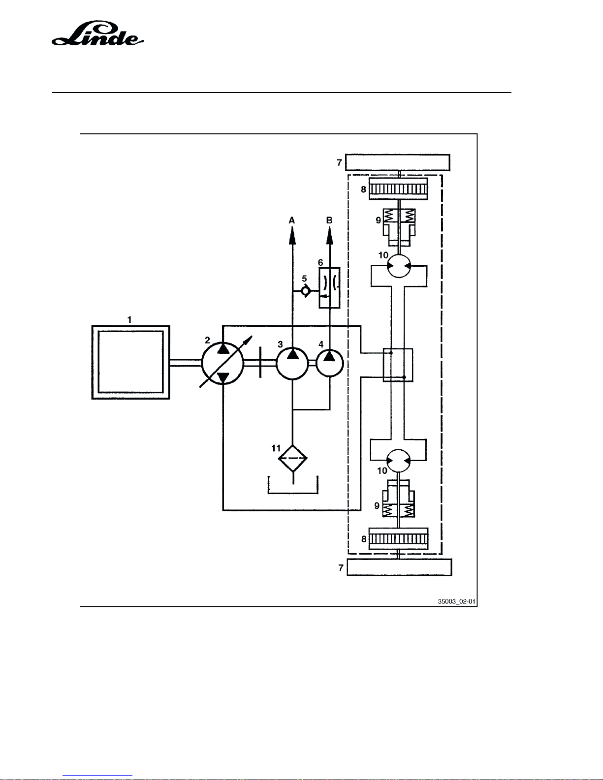
2.2 SCHEMATIC DIAGRAM OF THE DRIVE UNIT
1 Driving engine
2 Variable pump HPV 55 -02
3 Gear pump 14 cm³/rev
4 Gear pump 11 cm³/rev
5 Check valve
6 Priority valve
7 Drive gears
8 Planetary gear
9 Multiple disc brake
10 Hydraulic motor HMF 35 -02
11 Suction filter
A Working hydraulic system
B Steering - boost pressure
Page 31

Section 2
Page 5
Service Training
H01 / Chapter 1
350 804 4701.0400
2.3 TECHNICAL DATA OF THE TRAVEL DRIVE SYSTEM
VARIABLE DISPLACEMENT PUMP
Type HPV 55 -02
Number of pistons 7
Piston diameter 19 mm
Max. working pressure 420 bar
Boost/pilot pressure 17.5 bar
Swash angle 19.7°
RPM in vehicle 2300 rpm
Q Maximum of feed pump 16 - 17 l/min
Control hydraulic
Actuation
Linde Hydraulic Control LHC
Pump drive directly via flexible coupling
DRIVE AXLE
Type AH 20 -01
Two fixed displacement pumps HMF 35 -02
Number of pistons 7
Piston diameter 17 mm
Constant swash angle 20.8 °
REDUCTION GEARBOXES (PLANETARY GEAR)
Planetary reduction single speed
Total ratio 7.615 : 1
2 OIL PRESSURE - MULTI-DISC BRAKES
- on extended motor shaft
- fully encapsulated - running in oil bath
- only required as parking and emergency brake
TANDEM GEAR PUMP
1 working hydraulics pump 14 cm³
1 pump for steering, supply and control 11 cm³
Page 32

Service Training
Section 2
Page 6
H01 / Chapter 1
350 804 4701.0400
Page 33

Section 2
Page 7
Service Training
H01 / Chapter 1
350 804 4701.0400
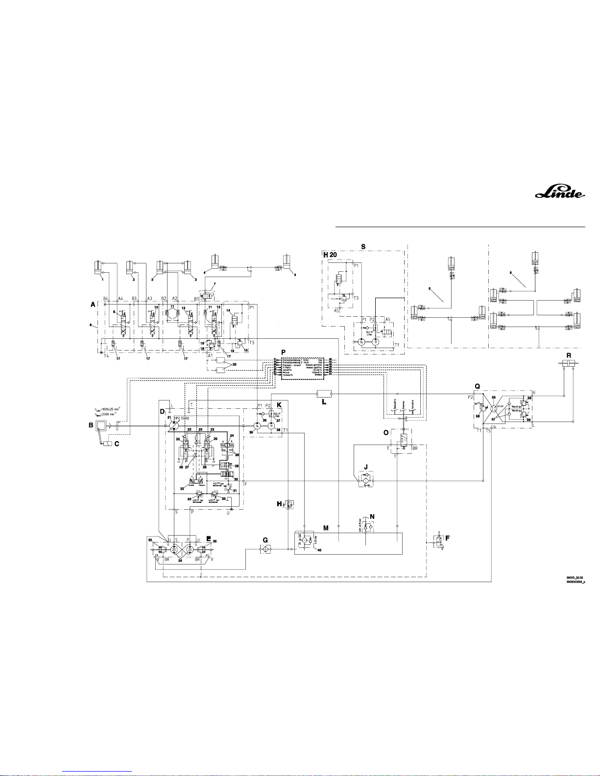
2.4 HYDRAULIC CIRCUIT DIAGRAM
A WORKING HYDRAULICS
1 Service cylinder (auxiliary hydraulics)
2 Service cylinder (auxiliary hydraulics)
3 Tilt cylinder
4 Lift cylinder, standard
5 Lift cylinder, duplex
6 Lift cylinder, triplex
7 Slow lowering valve
8 Control valve block, assy., including:
9 Way valve - auxiliary hydraulics
10 Way valve - auxiliary hydraulics
11 Check valve (pilot controlled)
12 Way valve - tilting
13 Way valve - lifting
14 2/2-way valve (pressure balance)
15 Maximum pressure valve
16 Restrictor
17 Shuttle valve
18 Pressure reducing valve
19 Restrictor
20 Pressure switch
B IC ENGINE
C ENGINE SPEED PROPORTIONAL SOLENOID
D VARIABLE PUMP HPV 55 -02, ASSY., INCLUDING:
21 Variable pump HPV 55 -02
22 Solenoid
23 Release valve
24 Spool
A = forward
B = reverse
25 Proportional valve
26 2/2-way valve
27 Nozzle
28 Servo circuit nozzles
29 4/2-way valve
30 Pilot valve
31 Boost pressure valve 17.5
+0.5
bar
32 Spool
Y = forward
Z = reverse
33 Combined boost and maximum pressure valve 420
+15
bar
E HYDRAULIC DRIVE AXLE AH 20 -01, ASSY., INCLUDING:
34 Hydraulic motors
35 Disc brakes
Page 34

Service Training
Section 2
Page 8
H01 / Chapter 1
350 804 4701.0400
F BYPASS VALVE
G OIL COOLER
H CHECK VALVE
J PRESSURE FILTER 9 mm
K Tandem pump, assy., including:
36 Check valve
37 Flow controller
38 Gear pump 11 cc/rev
39 Gear pump 14 cc/rev
L DAMPER
M HYDRAULIC OIL TANK
40 Suction filter 25 µm with bypass valve
N BREATHER FILTER WITH PRESSURISING VALVE 0.35 BAR
O BRAKE VALVE
P ELECTRONICS
41 RPM increase, stage 1
42 Free
43 RPM increase, stage 2
44 Free
45 Actual RPM
46 Brake pedal depressed
47 IC engine
48 Brake released
49 Forward (output signal)
50 Forward (output signal)
51 Emergency stop
52 Reverse (input signal)
53 Reverse (input signal)
54 Brake
Q STEERING CONTROL VALVE INCLUDING:
55 Steering control valve
56 Hose safety valve 190 ± 10 bar
57 Make-up valve
58 Pressure relief valve 120 bar
R STEER CYLINDER
S SPEED LIMITER FOR PUSHING OPERATION (H 20 ONLY)
59 Restrictor
60 2/2-way valve
Page 35
H01 / Chapter 1
350 804 4701.0400
Section 2
Page 9
Service Training
HYDRAULIC CIRCUIT DIAGRAM, H 12/16/18/20 D-03/T-03, SERIES 350
Page 36

Section 2
Page 10
Service Training
H01 / Chapter 1
350 804 4701.0400
Page 37
Section 2
Page 11
Service Training
H01 / Chapter 1
350 804 4701.0400
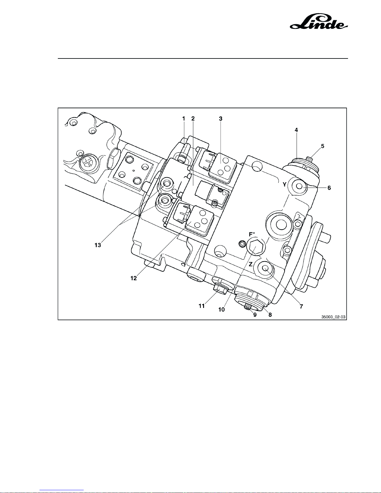
2.5 VIEW OF THE VARIABLE PUMP
1 Bypass valve
2 Release valve
3 Proportional valve - forward
4 Setting start of control - reverse
5 Maximum swash angle - reverse
6 Test port Y - forward servo pressure
7 Test port Z - reverse servo pressure
8 Setting start of control - forward
9 Maximum swash angle - forward
10 Test port for pilot pressure F" upstream of
release valve
11 Hydraulic zero setting
12 Proportional valve - reverse
13 HP test ports
Page 38
Service Training
Section 2
Page 12
H01 / Chapter 1
350 804 4701.0400
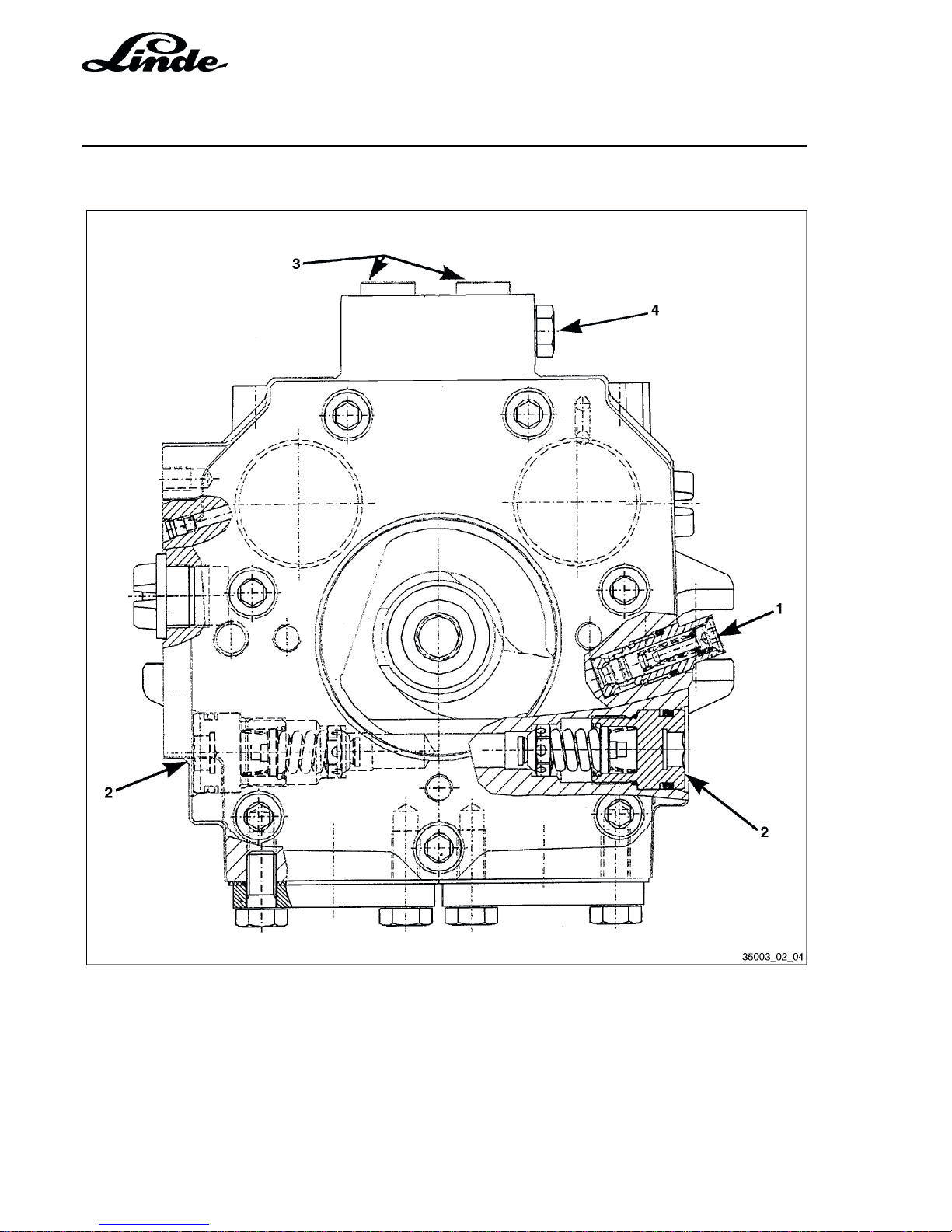
2.6 CROSS SECTIONAL VIEW OF DRIVE PUMP
1 Boost pressure valve
2 High pressure relief valves
3 High pressure test ports (forward and reverse)
4 Short circuit valve (towing valve)
Page 39
Section 2
Page 13
Service Training
H01 / Chapter 1
350 804 4701.0400
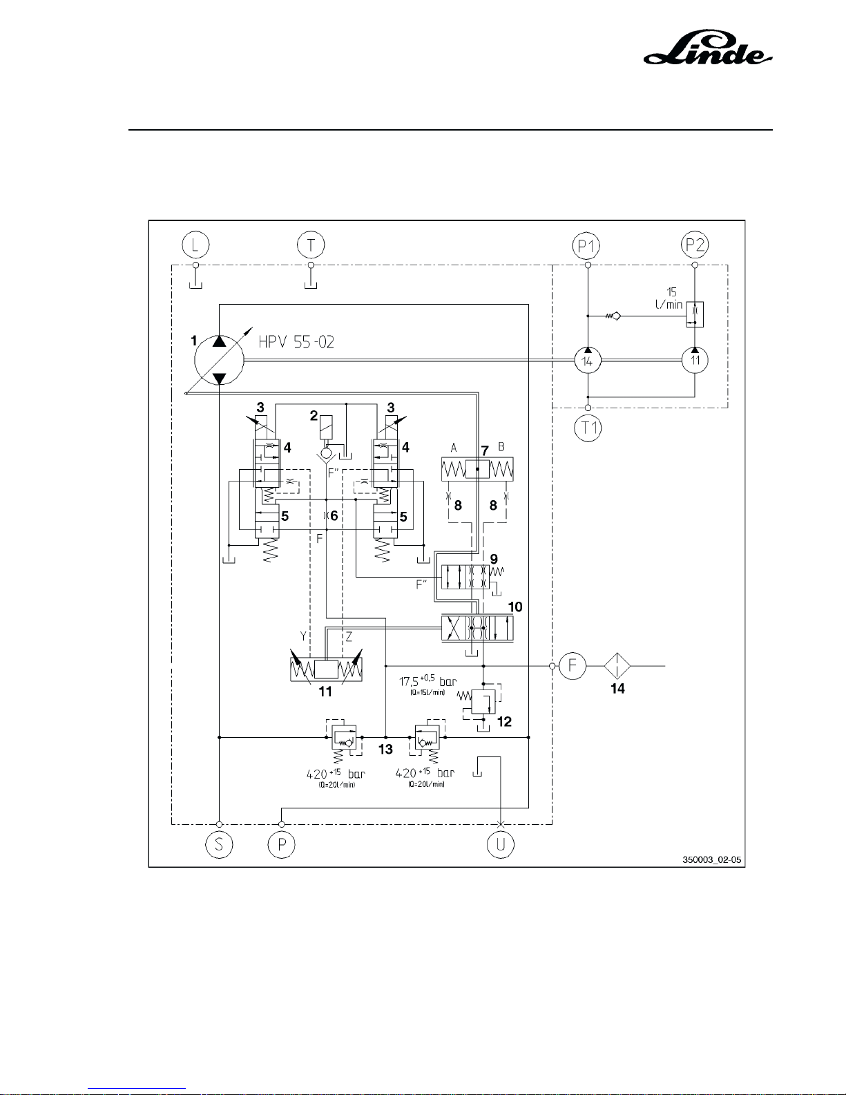
2.7 ELECTRIC-HYDRAULIC ADJUSTMENT
CIRCUIT DIAGRAM
1 Hydraulic variable pump HPV 55 -02
2 Release valve
3 Solenoid
4 Proportional valve
5 2/2-way valve
6 Nozzle Ø 1 mm
7 Spool
8 Servo circuit nozzles
9 4/2-way valve
10 Pilot valve
11 Spool
12 Boost pressure valve
13 Combined boost and maximum pressure valve
14 Change filter
Page 40

Service Training
Section 2
Page 14
H01 / Chapter 1
350 804 4701.0400
FUNCTIONAL DESCRIPTION
When the engine is running and the brake pedal is depressed, the solenoid of the release valve (2) is deenergised. Boost pressure is applied from port F to nozzle (6); the passage behind the nozzle, however, is
connected to tank via the open release valve (2) and is thus without pressure.
The spool (7) is connected to port F on both sides via the pilot valve (10), the way valve (9) and the servo
circuit nozzles (8), thus holding the variable pump (1) in the hydraulic neutral position.
After the electronic controller has released the switching signal to the release valve (2), the valve closes the
connection to tank so that boost pressure also rises behind the nozzle (6). The two way valves (5) are set
to the open position so that boost pressure from passage F is applied to the unactuated proportional valves
(4). Simultaneously, the way valve (9) is shifted from the throttled to the unthrottled position.
Depressing an accelerator pedal controls the respective solenoid (3) with a pedal-dependent signal. A
pressure corresponding to the signal value of the solenoid is applied through the downstream proportional
valve (4) to the spool (11). The spool (11) moves and pushes the oil flowing off at the opposite end of the
spool through the respective proportional valve (4) into the tank. The operation of the spool (11) adjusts the
pilot valve (10) through which the spool (7) is supplied with pressure and the pump starts delivering.
Releasing the accelerator pedal towards zero stroke reduces the signal at the solenoid. As a result, the
proportional valve reduces the pressure going to the spool, the pump reduces the swashplate angle and the
truck is braked.
When the electronic controller detects an error in the speed control, the truck must be brought to a controlled
stop, independent of the position of the accelerator pedal.
To do this, the release valve (2) is de-energised so that the pressure behind the nozzle (6) will drop to 0 bar.
The way valves (5) move to the closed position, thus removing the boost pressure going to the proportional
valves (4). This action also shifts the proportional valve (4), which is controlled by the solenoid (3),
mechanically to the home position and the pressure applied to the spool (11) is removed. The piston is pushed
mechanically to the zero position, which also shifts the pilot valve (10) to the zero position. The opening of
the release valve (2) and the concomitant pressure drop to 0 bar also switches the way valve (9) from the
unthrottled to the throttled position.
The reset time for the spool (7), and therefore also for the braking deceleration, is metered with the servo
circuit nozzles (8) and the throttling with the way valve (10). This arrangement prevents sudden braking.
EMERGENCY STOP WITH THE BRAKE PEDAL
If, due to a fault, the truck can no longer be braked with the accelerator pedals, it is possible to make an
emergency stop with the brake pedal.
Depressing the brake pedal actuates the microswitches in the pedal console. This cuts off the power to the
release valve (2) and the truck is brought to a controlled stop as with a fault in the controller. The brake release
pressure at the disc brakes is also reduced and the truck is thus also braked mechanically.
Page 41
Section 2
Page 15
Service Training
H01 / Chapter 1
350 804 4701.0400
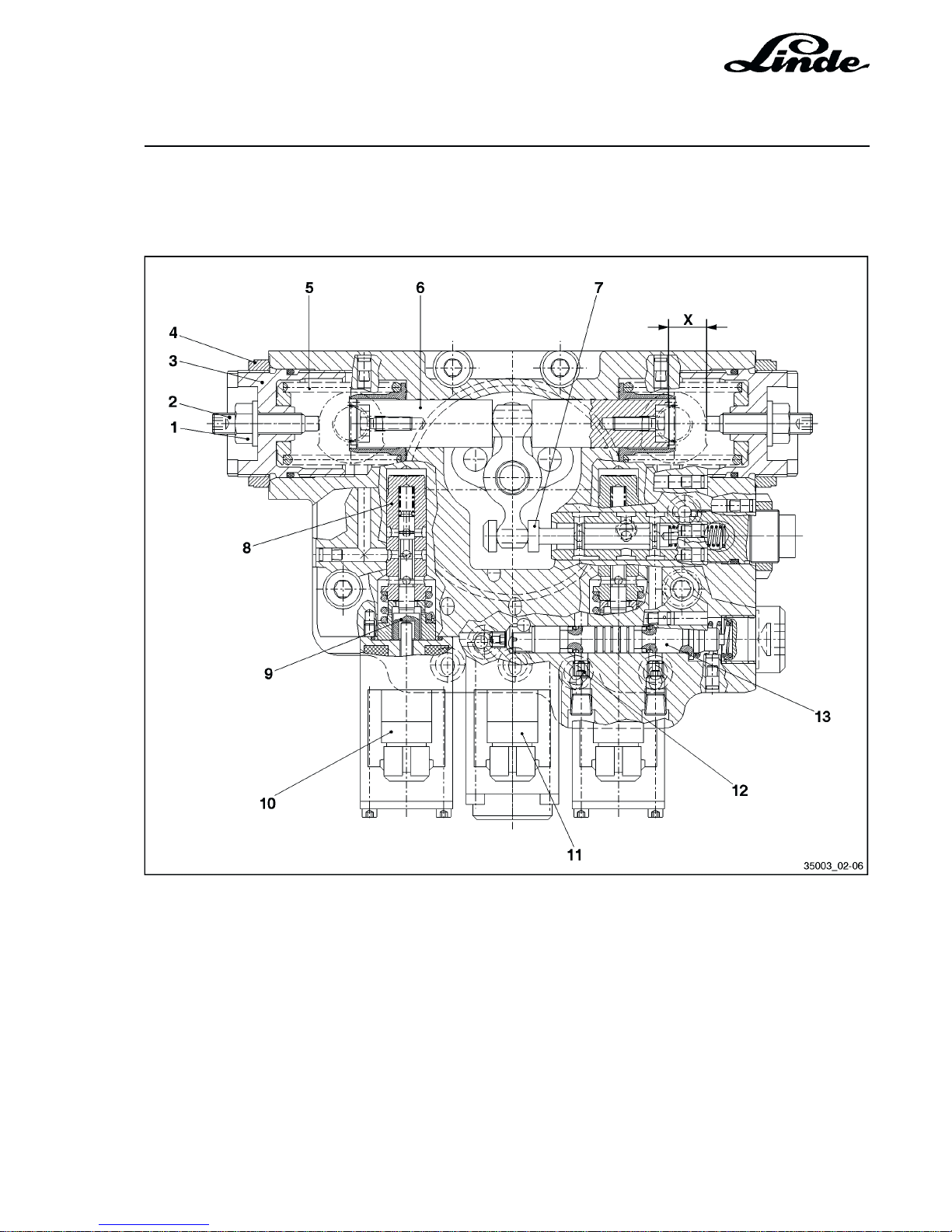
9 Proportional valve
10 Solenoid
11 Release valve
12 Servo circuit nozzles
13 Way valve
X Travel of servo piston 15.1 mm
1 Locknut
2 Swashplate angle setscrew
3 Setting bush - start of control
4 Locknut
5 Control spring
6 Spool
7 Control pilot
8 Way valve
2.7.1 HYDRAULIC ADJUSTMENT WITH ELECTRONIC CONTROL
Page 42
Service Training
Section 2
Page 16
H01 / Chapter 1
350 804 4701.0400
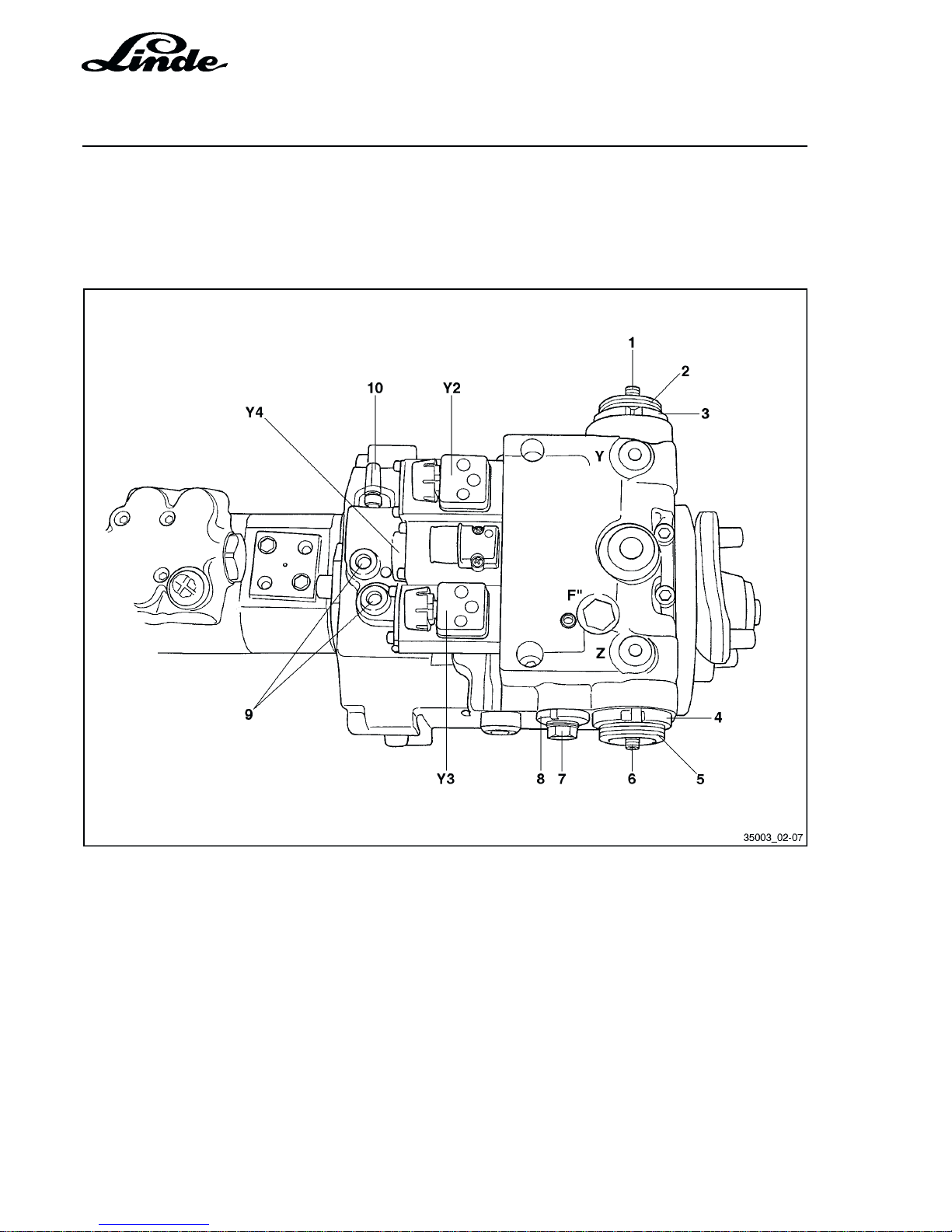
2.7.2 ELECTRIC-HYDRAULIC CONTROL
- Begin of pump control
- Max. swash angle of pump
- Hydraulic zero position
Setting the start of control and swash angle,
reverse
1 Adjusting pin (swash angle max.)
2 Set ring (start of control) wheel begin
3 Slotted nut (start of control) wheel begin
Setting start of control and swash angle,
forward
4 Slotted nut (start of control) wheel begin
5 Set ring (start of control) wheel begin
6 Adjusting pin (swash angle max.)
Setting the hydraulic zero position
7 Pilot housing
8 Slotted nut
9 HP test port
10 Towing bypass valve
F" Servo pressure - upstream of release
valve (test point)
Y Pilot pressure, forward
Y2 Control magnet, forward
Y3 Control magnet, reverse
Y4 Release valve
Z Reverse pilot pressure
Page 43
Section 2
Page 17
Service Training
H01 / Chapter 1
350 804 4701.0400
2.7.2.1 BEGIN OF PUMP CONTROL
Precondition:
- Jack up and support the truck and block 1 wheel.
- Start the engine and release the brake pedal.
- Connect the diagnostics module or laptop and select window 6.
- Depress the forward and reverse accelerator pedals until iY2 or iY3 = 440 - 460 mA.
- Hold the accelerator pedal in this position, loosen the slotted nut (4) and turn the adjustment ring (5) on
the servo cover until the wheel just begins to turn. Then lock the slotted nut (4) again.
If iY3 = 440 - 460 mA, perform the same adjustment at the set ring (2).
- Release the blocked wheel.
- Fully depress the blocked wheel. A value of 1180 mA must be obtained in window 6 of the diagnostics
module or laptop (specified by the computer).
- Determine the average wheel revolutions (desired value 210 RPM).
Q = oil flow
Accelerator pedal stroke
440 - 460 mA 1180 mA
Q = 0 Q = max
Start of traction wheel rotation
Release valve actuated
If the electronic data is correct, but the wheels do not rotate or the full wheel RPM is not achieved, check
and adjust, if necessary, the stroke of the servo piston (swash angle).
2.7.2.2 SWASH ANGLE OF VARIABLE PUMP
- Block up the truck and block 1 wheel.
- Start the engine and release the brake pedal.
- Loosen the adjusting pin locknut (1) on the Y side of the controller and turn in the setscrew (1) until the
free wheel just begins to rotate.
- Then turn the adjusting pin (1) out for 12 turns and relock the locknut.
- Repeat the same procedure on side Z .
2.7.2.3 HYDRAULIC ZERO POSITION
- Jack up the truck and block 1 wheel.
- Start the engine and release the brake.
- Loosen the slotted nut (8) and turn the pilot housing (7) to one side until the free wheel begins to rotate.
Then turn the pilot housing in the opposite direction until the wheel rotates in the other direction. Half the
travel of the pilot housing between the start of forward and reverse wheel rotation and lock the slotted nut.
- Release the blocked wheel.
- Bring the engine to full speed by hand. If the wheels are still rotating after the adjustment, perform the
adjustment again.
Page 44
Service Training
Section 2
Page 18
H01 / Chapter 1
350 804 4701.0400
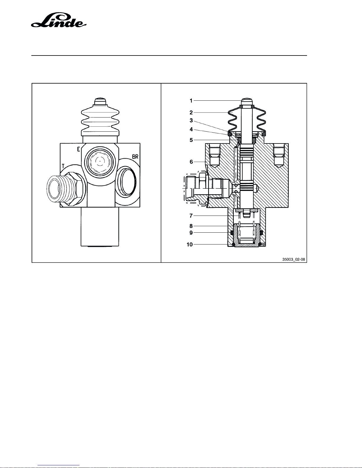
2.7.2.4 HYDRAULIC BRAKE VALVE
1 Valve spool
2 Boot
3 Snap ring
4 Washer
5 Slotted ring
6 Valve housing
7 Return spring
8 Spring plate
9 O-ring
10 Snap ring
BR Outlet to multiple disc brake
E Boost pressure oil inlet
T Tank port
When the engine is running, boost pressure is applied to port “E”. When the brake pedal is released, E and
BR are connected = brake released; when the brake pedal is depressed, BR-T is connected = brake applied.
Page 45
Section 2
Page 19
Service Training
H01 / Chapter 1
350 804 4701.0400
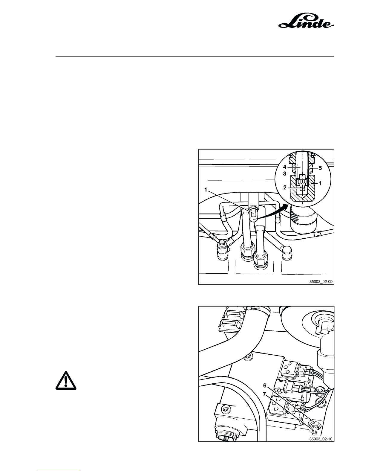
2.8 TOWING DEVICE
To allow a truck to be towed, two conditions must be fulfilled:
- The multiple disc brake must be released.
- The towing bypass valve must be set to the towing position.
PREPARING THE TRUCK FOR TOWING
Releasing the multiple disc brake:
- Remove the cover at the front of the truck.
- Remove the cap nut (1) and sealing ring (3).
- Slacken the locknut (5).
- Turn in the setscrew (4) as far as possible and
torque it to 10 Nm.
- Lock the setscrew with the locknut (5). Tighten
the nut to 25 Nm.
- Using a grease gun, apply about 4 shots of
grease through grease nipple (2) until the brake
is released.
Opening the hydraulic bypass valve:
- Open the bonnet.
- Loosen the 19 mm locknut (6) at the variable
pump.
- Loosen the 8 mm pin (7) by three turns with a
socket.
- Lock the setcrew with the locknut (6), torque to
40 Nm.
CAUTION
The truck can not be braked.
NOTE: After towing, return the grease nipple
and bypass valve to the initial position.
Page 46
Service Training
Section 2
Page 20
H01 / Chapter 1
350 804 4701.0400
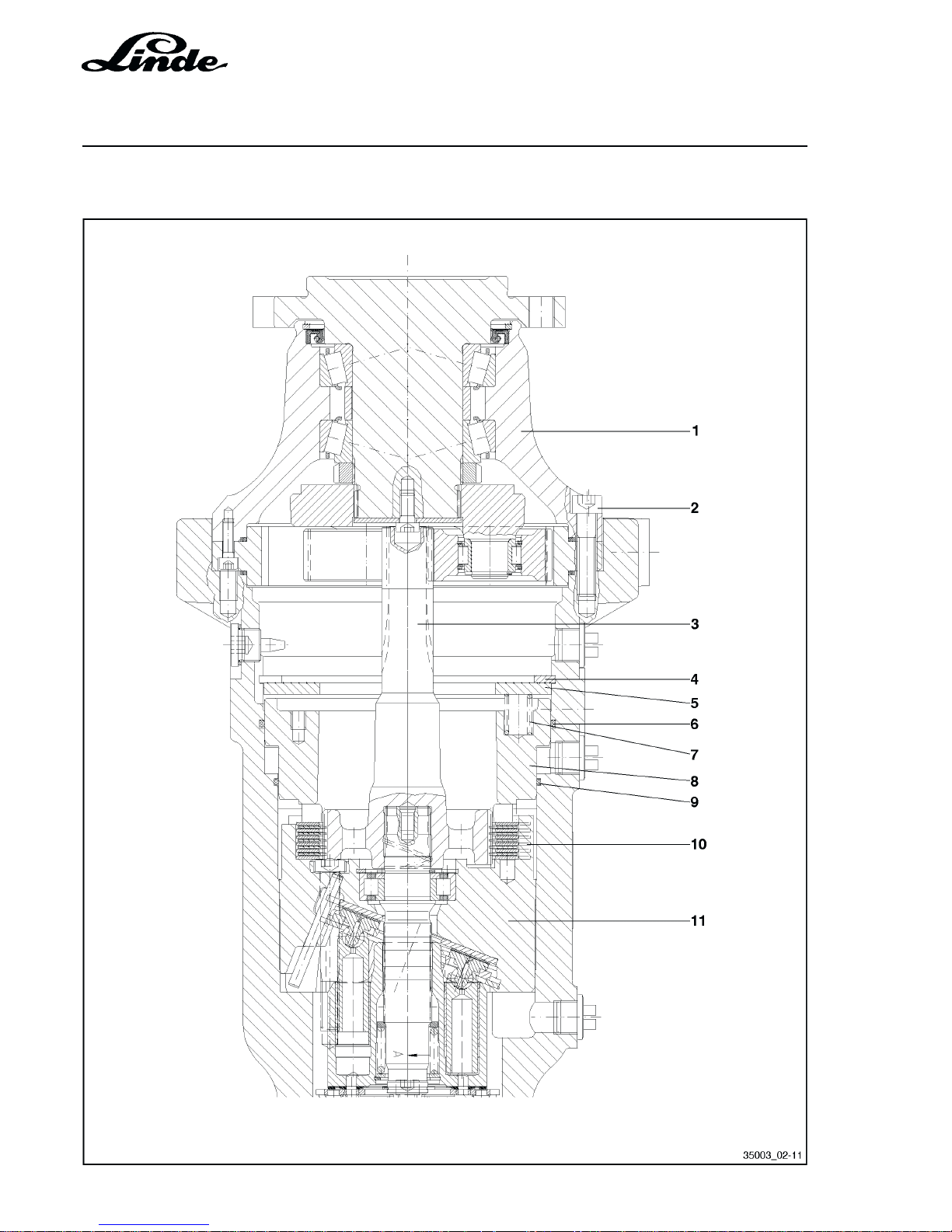
2.9 DRIVE AXLE AH 20 -01 WITH WHEEL DRIVE, MULTIPLE DISC BRAKE AND HYDRAULIC
MOTOR
Page 47

Section 2
Page 21
Service Training
H01 / Chapter 1
350 804 4701.0400
1 Planetary gear assembly
2 Allen screw
3 Drive shaft
4 Snap ring
5 Pressure plate
6 O-ring
7 Brake spring
8 Brake piston
9 O-ring
10 Brake discs
11 Swashplate with hydraulic motor assembly
Page 48
Service Training
Section 2
Page 22
H01 / Chapter 1
350 804 4701.0400
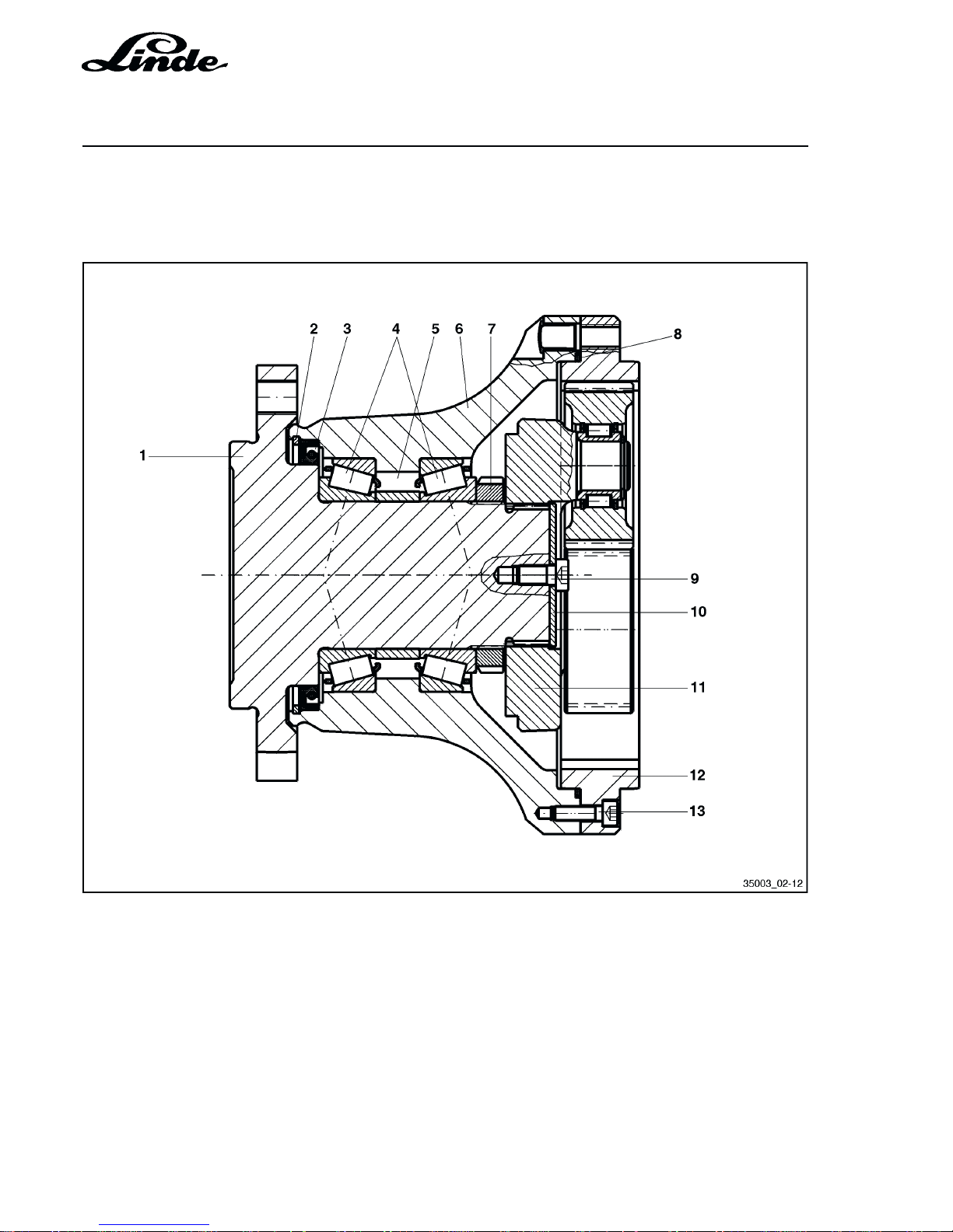
2.9.1 REPAIRING THE REDUCTION GEAR, MULTIPLE DISC BRAKE AND HYDRAULIC MOTOR
Reduction gear assembly (planetary gear):
1 Wheel shaft
2 Snap ring
3 Radial sealing ring
4 Tapered roller bearing
5 Spacer (bearing adjustment)
6 Gearbox
7 Slotted nut
8 O-ring
9 Allen screw
10 Retaining plate
11 Planetary carrier assembly
12 Internal gear
13 Allen screw
Page 49
Section 2
Page 23
Service Training
H01 / Chapter 1
350 804 4701.0400
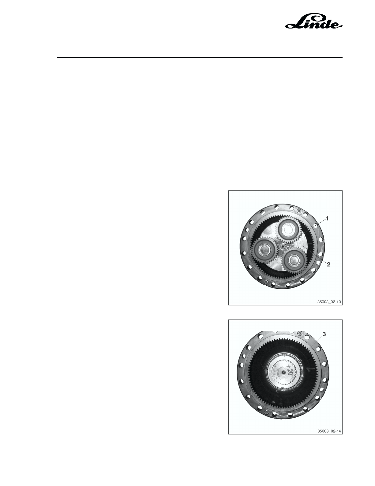
2.9.2 RENEWING THE RADIAL SEALING RING OF THE PLANETARY GEAR
Precondition:
- Wheel drive removed from AH 20 -01 axle.
Required special tools.
- Grooved nut key
- Drift
- Torque wrench up to 700 Nm.
REMOVAL
Remove the screw (1) and pull the planetary carrier (2) out
of the gearbox.
Heat the nut (3) (to loosen the Loctite).
Page 50
Service Training
Section 2
Page 24
H01 / Chapter 1
350 804 4701.0400
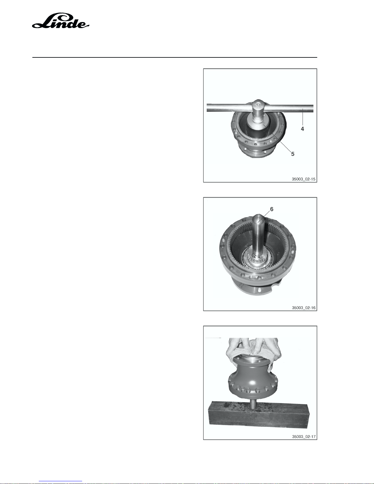
Remove the slotted nut with a grooved nut key (5) and Tsliding handle socket wrench (4). (Hold the wheel shaft, eg
in a vice.)
Screw a drift (6) into the wheel shaft.
Drive the wheel shaft out of the gearbox by impacting the
drift on a hard surface.
Page 51
Section 2
Page 25
Service Training
H01 / Chapter 1
350 804 4701.0400
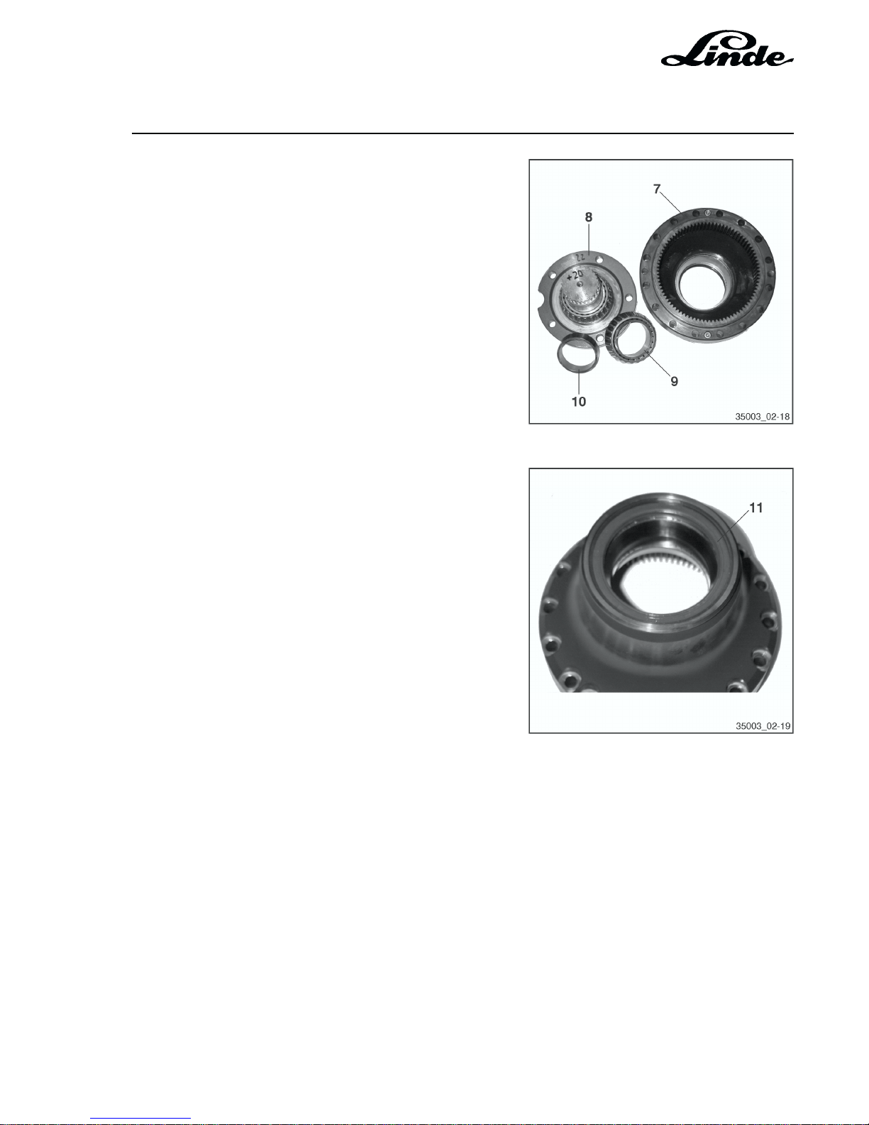
Removed wheel shaft
7 Gearbox
8 Wheel shaft
9 Bearing
10 Spacer (bearing adjustment)
Remove the radial sealing ring (11) from the casing.
ASSEMBLY
After cleaning all parts, carry out the assembly in the reverse order or disassembly. Secure the nut (3) and
screw (1) with Loctite 270.
Torque for nut (3): 650
+ 50
Nm.
Page 52
Service Training
Section 2
Page 26
H01 / Chapter 1
350 804 4701.0201
02.01
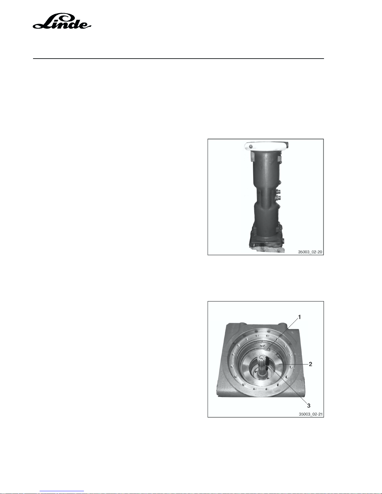
2.9.3 REMOVING AND INSTALLING THE MULTIPLE DISC BRAKE AND HYDRAULIC MOTOR
WITH SWASHPLATE
NOTE: For the following procedures you do not
have to remove the axle from the truck.
REMOVAL
Multiple disc brake
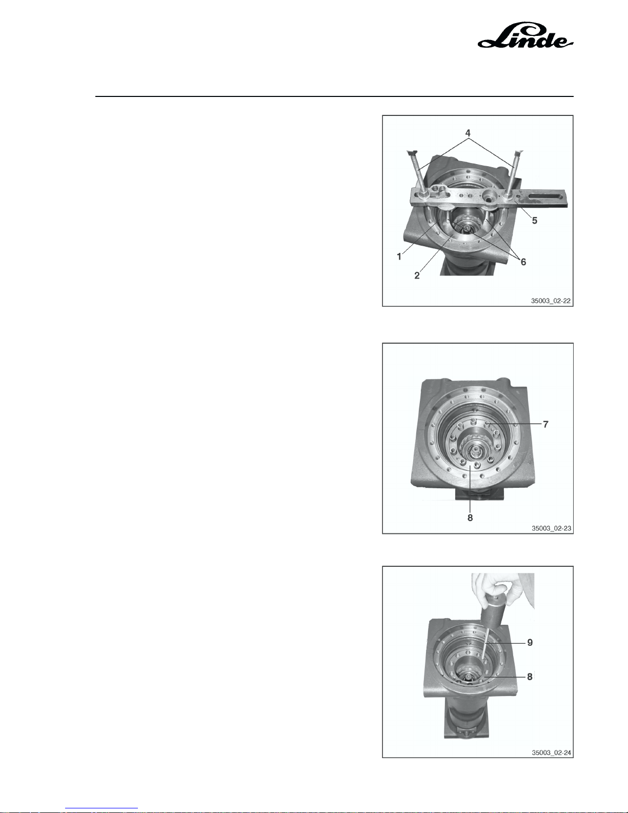
1 Snap ring
2 Disc (on brake springs)
3 Drive shaft
Draw the drive shaft (3) out of the brake discs.
Page 53
Section 2
Page 27
Service Training
H01 / Chapter 1
350 804 4701.0400
Prestress the disc (2) with threaded rods (4), bar (5) and
distance pins (6), pry out the snap ring (1) and take the disc
(2) out of the axle tube.
Take the brake springs (7) out of the brake piston (8).
Screw a M8 impact driver (9) into the brake piston (8) and
drive out the brake piston.
Page 54
Service Training
Section 2
Page 28
H01 / Chapter 1
350 804 4701.0400
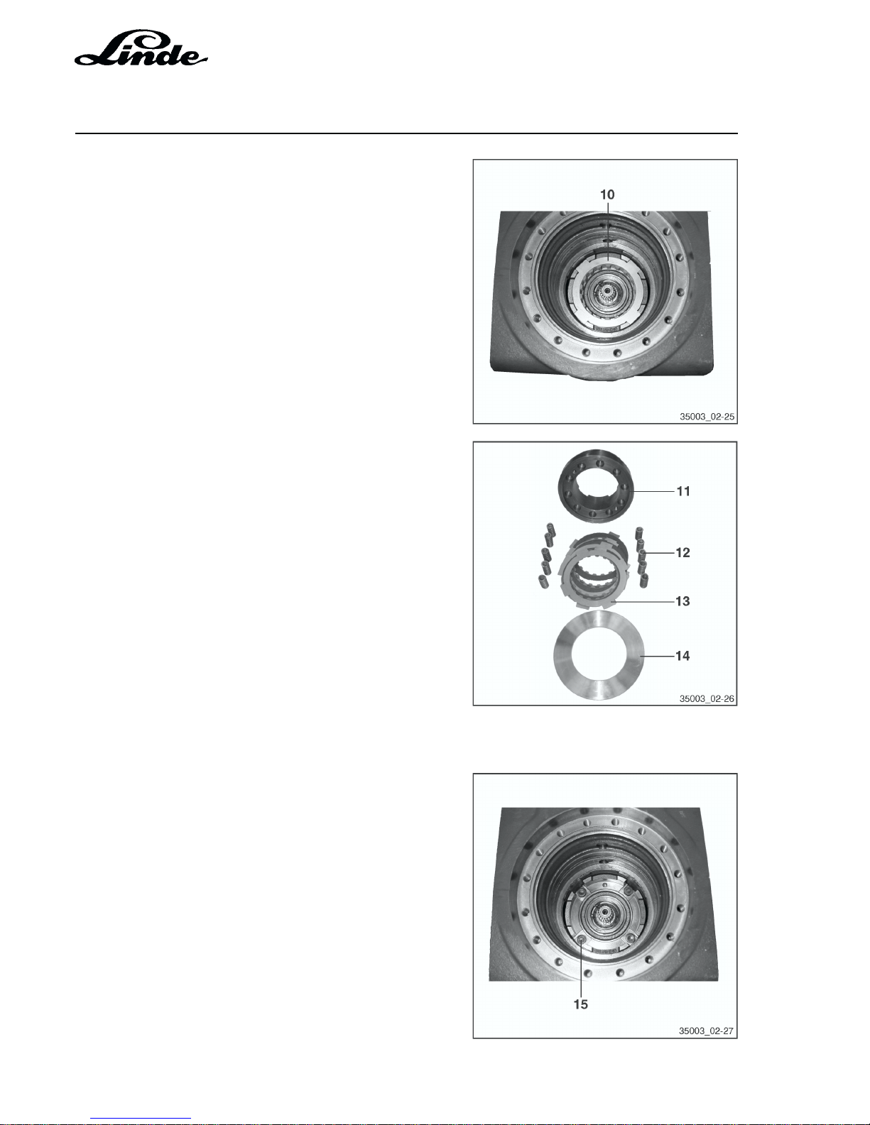
Remove all discs (10) and take the two O-rings out of the
axle tube.
Brake removed
11 Brake piston
12 Springs
13 Brake discs
14 Disc
HYDRAULIC MOTOR WITH SWASHPLATE
Remove the fastening screws (15) (4 items).
Page 55
Section 2
Page 29
Service Training
H01 / Chapter 1
350 804 4701.0400
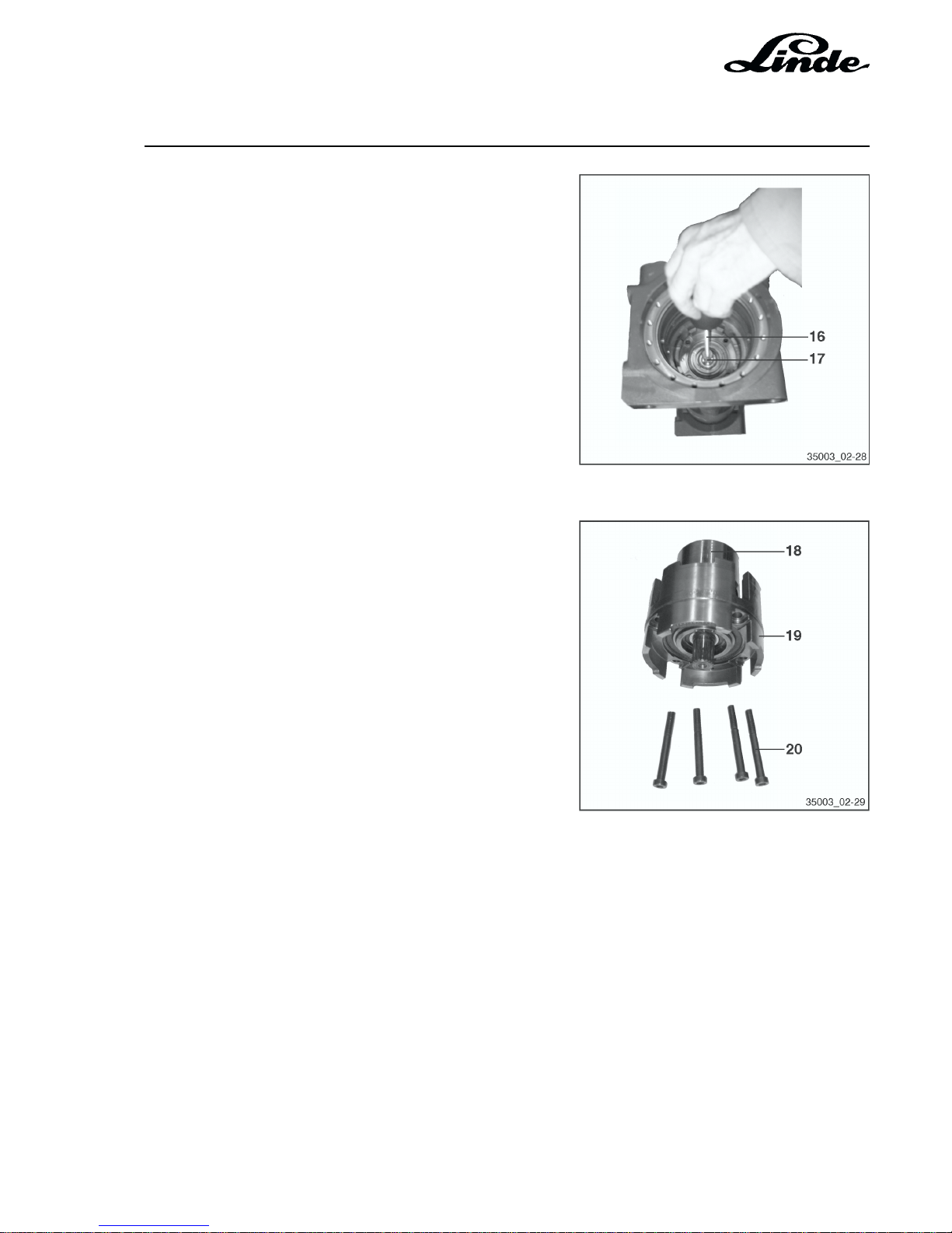
Screw the M8 impact driver (16) into the hydraulic motor
shaft (17) and pull out the swashplate along with the
hydraulic motor.
Hydraulic motor assembly
18 Cylinder block
19 Swashplate with disc carrier
20 Fastening screws
ASSEMBLY
After cleaning all parts, assemble all parts in the reverse order of disassembly. Renew defective parts and
both O-rings.
Torque for screws (20) : 64 Nm.
Page 56
Service Training
Section 2
Page 30
H01 / Chapter 1
350 804 4701.0400
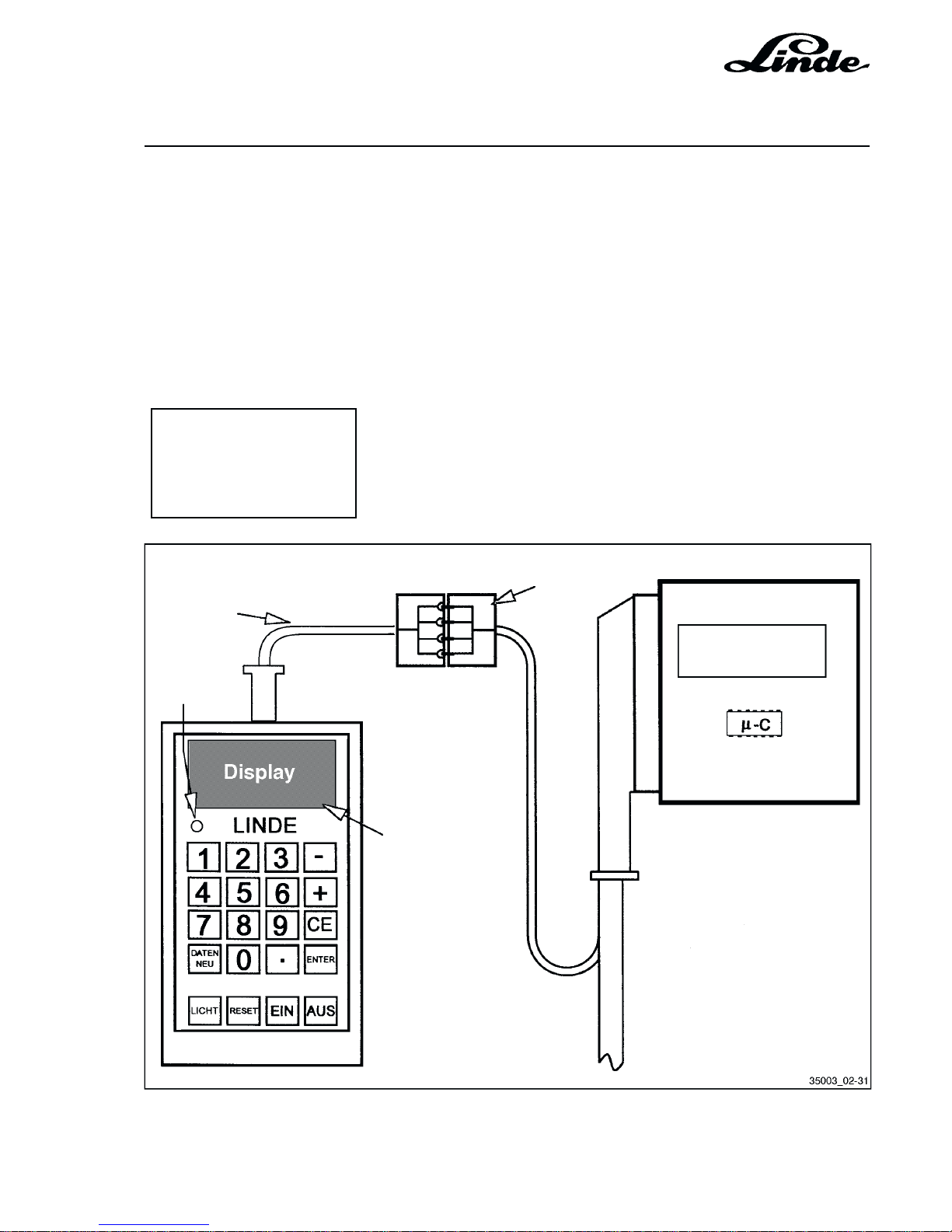
LINDE DIAGNOSTIC MODULE
PC SCREEN
DISPLAY
2.10 TRUCK DIAGNOSTICS AND TROUBLESHOOTING
As traction and speed are controlled electrically and hydraulically, the check is also divided into electric and
hydraulic tests.
For the diagnostics of the electrical system, the Linde test module or a PC (Laptop) is required. The hydraulic
test case is required for the check of the hydraulic section.
2.10.1 ELECTRICAL SYSTEM DIAGNOSTICS
It is possible to communicate with the LHC digital controller via an ISO interface. The LDC digital controller
can be diagnosed by starting the diagnostic program or connecting the Linde diagnostic module. The
selected windows are identical, independent of the diagnostic equipment used (PC or Linde diagnostic
module). If a PC is used, additional information is displayed at the bottom of the PC screen. Furthermore,
the PC permits parameters to be stored and printed out on an attached printer.
WINDOW
Page 57
Section 2
Page 31
Service Training
H01 / Chapter 1
350 804 4701.0400
2.10.1.1 WORKING WITH THE LINDE TEST MODULE
Conditions
- Traction wheels of truck off the ground
- Accelerator pedals in neutral position
- Brake pedal held in braking position
- Ignition switched off
Before using the Test Module, check if it is operational by pressing the EIN (ON) button. The following
information will be displayed:
--------------------
* Linde Test Modul * Software version and version date
* V2.27-P 10/96 St * of the module
* Terminal ready * Module is operational
* No data received * No data received
--------------------
Linde
LHC Electronics
LHC Diagnostic
Cable
Truck Diagnostic
Connector
Wiring Loom
Data in display
is updated
every ½ s
4 Leads:
2 x Power Supply Leads
2 x Signal Leads
Red
Warning
Lamp
Page 58

Service Training
Section 2
Page 32
H01 / Chapter 1
350 804 4701.0400
NOTE: The Test Module will only work if the EPROM version V2.26-P, V2-27-P or a higher version is
installed. If no or the wrong information appears after the EIN (ON) button is depressed, replace
the batteries and check the Test Module.
- Connect the Test Module to the diagnostics connector of the controller.
NOTE: The connector, sealed with a cap, is fastened in a holding angle bracket on the control lever
console.
- Turn on the ignition; the red warning lamp will flash.
NOTE: If the red warning lamp is not flashing, check fuse 1F17 and the cable connection and power
supply from the controller to the diagnostics connector. Also check the adapter cable from the
connector to the Test Module.
If the connection is correct, window 1 will be displayed.
The other windows can be selected by pressing the appropriate buttons.
NOTE: After the ignition is turned on, the fault lamps 1H20 (up to 05/98, from 06/98 H2) will light steady.
(Lamp and cable connection self-test.)
The lamp will go off when the engine is running.
2.10.1.2 DIAGNOSTICS WITH A PC AND THE LINDE INTERFACE CONVERTER
System requirements for the PC or the notebook:
Operating system: MS-DOS 5.0 or higher must be installed
Microsoft Windows 3.10 or higher can be installed
Microsoft Windows 95 or higher can be installed
RAM storage
requirement: minimum 512 Kbytes for DOS operating system
minimum 4 Mbytes for Windows operating system
Hard disc storage
requirement: minimum: 1 Mbyte for DOS operating system
Monitor requirement: DOS operating system:
recommended: VGA resolution (640 x 480 pixel) monochrome
Windows operating system:
minimum: VGA resolution (640 x 480 pixel) monochrome
recommended: VGA resolution (640 x 480 pixel) colour
Page 59

Section 2
Page 33
Service Training
H01 / Chapter 1
350 804 4701.0400
2.10.1.2.1 LINDE INTERFACE CONVERTER
The Linde interface converter must be used to communicate between the PC and the appropriate LDC digital
controller. The digital controller has a 4-pin diagnostics connector which uses the ISO protocol for data
transfer. The serial interface of the PC uses the RS232 protocol. The interface converter converts signals
between the two protocols , thus permitting communication between the PC and digital controller and vice
versa.
The data transfer uses 9600 baud, 8 bit data, 1 stop bit and no parity. The interface converter is connected
between the 9 pole sub-D terminal of the serial interface of the PC and the 4 pole AMP-Saab connector to
the diagnostics connector on the digital controller. The second 6 pole AMP connector is used for connection
to other Linde vehicles (E 10, P 60) which are equipped with a Zapi control system. This latter system has
a serial electrical interface for data transfer.
The diagnostic software normally uses the serial interface COM1 of the PC. If this connector is already in
use, it is necessary to convert to the COM2 serial interface. This procedure is included in the installation
procedures.
The interface converter is delivered with the appropriate diagnostic software.
2.10.1.2.2 INSTALLATION OF THE DIAGNOSTIC SOFTWARE “TEST & SETUP”
The diagnostic software is available as a master program or as a service program. The master program
permits access to all truck parameters. The master program can only be ordered through the customer
service school. The service program permits access only to the service functions (fault storage, switching
conditions, etc.) and can be ordered from the Linde spare parts organisation.
Both software programs are available as a complete program or as an update program. When a complete
program has been installed on a computer, only an update program is required in the future.
The diagnostic software is delivered on 3.5 inch diskettes. The diagnostic software version is identified on
the diskette labels. In addition the following is noted; master or service program and if it is a complete program
or only an update program.
e.g. Software version: V1.3-P
The diagnostic software is available in German, English or French. The desired language must be selected
during the installation process.
The diagnostic software cannot be copied and can only be installed on an appropriate computer once.
Through installation on a computer, the user accepts the conditions of the software license. When a master
program is ordered, the updates are provided automatically. Updates for the service program can be ordered
from the Linde spare parts organisation.
Page 60

Service Training
Section 2
Page 34
H01 / Chapter 1
350 804 4701.0400
INSTALLATION INSTRUCTIONS FOR COMPLETE PROGRAM (MASTER AND SERVICE PROGRAMS)
- Go to the DOS operating system.
- Insert the diskette 1 into the disc drive.
- Select the appropriate disc drive, e.g. disc drive A: and press ENTER.
- INSTALL <source disc drive>: <destination disc drive:> : <language> <serial interface>.
NOTE: The desired language is selected by typing a number after the destination disc drive letter;
1 = German, 2 = English, 3 = French. Furthermore, the correct serial interface must be selected;
1 = COM1, 2 = COM2.
- E.g. For an installation in German on serial interface COM1, type the following command; INSTALL A:
C: 1 1 and press ENTER.
- A directory named “lindiag.dos” will be created in the hard drive and the software on the diskette will now
be copied into the directory on the hard disc.
- Insert diskette 2 when prompted and press the RETURN key.
- Type DIAG and press ENTER. A window “TRUCK SELECTION” appears, on which the appropriate
diagnostic program can be selected.
- Press the cursor up é or down ê arrow to select the diagnostic program.
- To start the selected diagnostic program press ENTER.
INSTALLATION INSTRUCTIONS FOR UPDATE PROGRAM (MASTER AND SERVICE PROGRAMS)
NOTE: A software update can only be made when the computer already has a complete program.
- Go to the DOS operating system.
- Insert the diskette 1 into the disc drive.
- Select the appropriate disc drive, e.g. disc drive A: and press ENTER.
- ENTER UPDATE <source disc drive>: <destination disc drive:> : <language> <serial interface>.
- E.g. For an installation in German on serial interface COM1, type the following command; UPDATE A:
C: 1 1 and press ENTER.
- Insert diskette 2 when prompted and press the RETURN key.
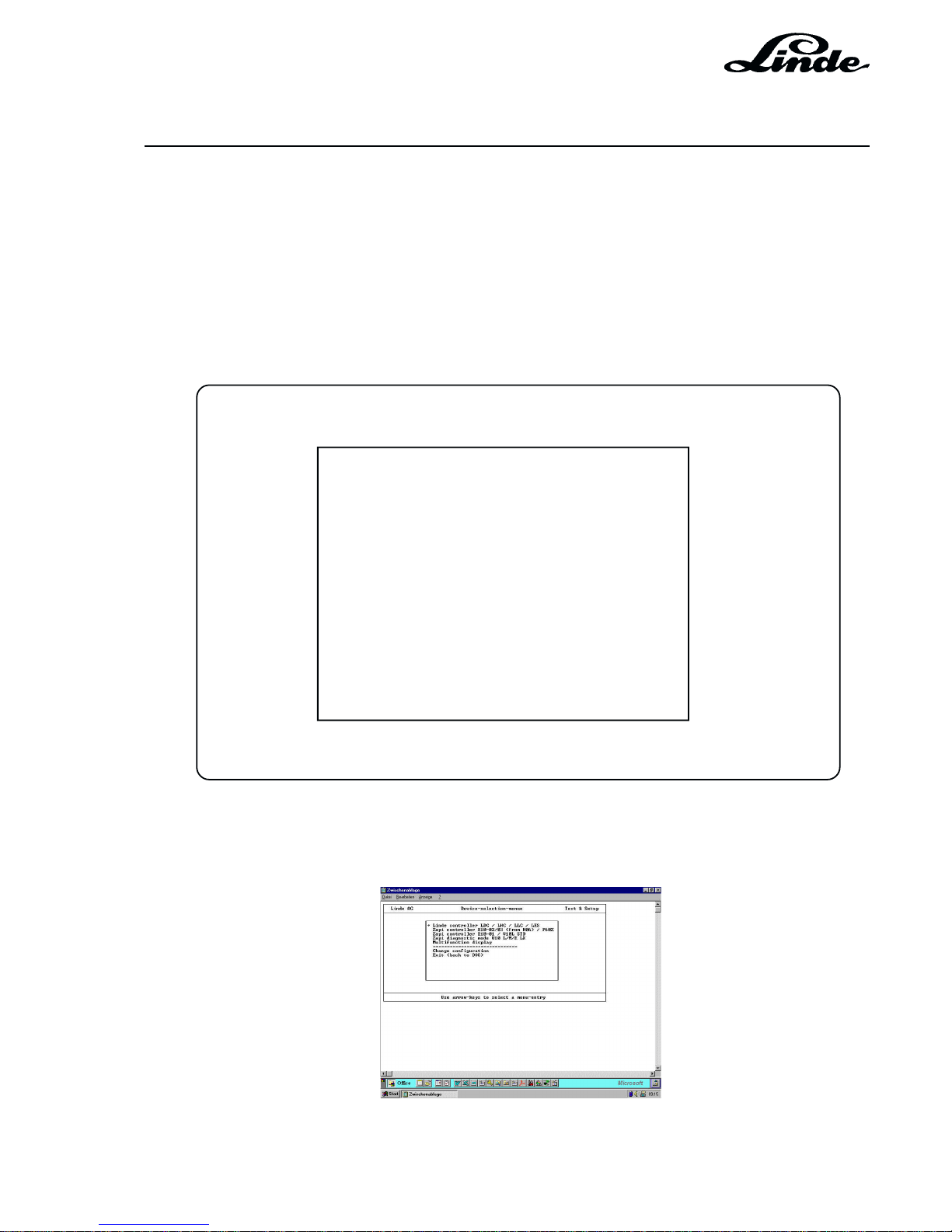
2.10.1.2.3 SELECTING THE LINDE PROGRAM
- Go to the DOS operating system (root directory c:\).
- Enter cd lindiag.dos.
- Open the window by typing DIAG and press ENTER.
- A window appears with the appropriate programs.
- Press the cursor up é or down ê arrow to select the program.
Page 61
Section 2
Page 35
Service Training
H01 / Chapter 1
350 804 4701.0201
02.01
2.10.1.2.4 STARTING THE DIAGNOSTIC PROGRAM “TEST & SETUP”
- Press the cursor up é or down ê arrow to place the arrow beside the fork truck model 350. Starting
with software version 1.5-P, select the LHC controller.
- The selected model (controller type) is identified with the arrow.
- Press the ENTER key.
- The Linde diagnostic program starts.
SELECTION WINDOW UP TO SOFTWARE VERSION 1.4
Linde AG Equipment Program Selection Test&Setup
Series 335 E 14/16/16C/18/20
Series 336 E 20/25/30
Series 350 H 12/16/18
============================
Series 144 T20S/T20R
Series 149 N20
Series 360 T 16/18/20
Series 379 L 10/12
Series 126 P60Z
Combined Instrument
============================
Change configuration
End program (return to DOS)
Select equipment program with cursor up or down key
->
SELECTION WINDOW FROM SOFTWARE VERSION 1.5
Page 62
Service Training
Section 2
Page 36
H01 / Chapter 1
350 804 4701.0400
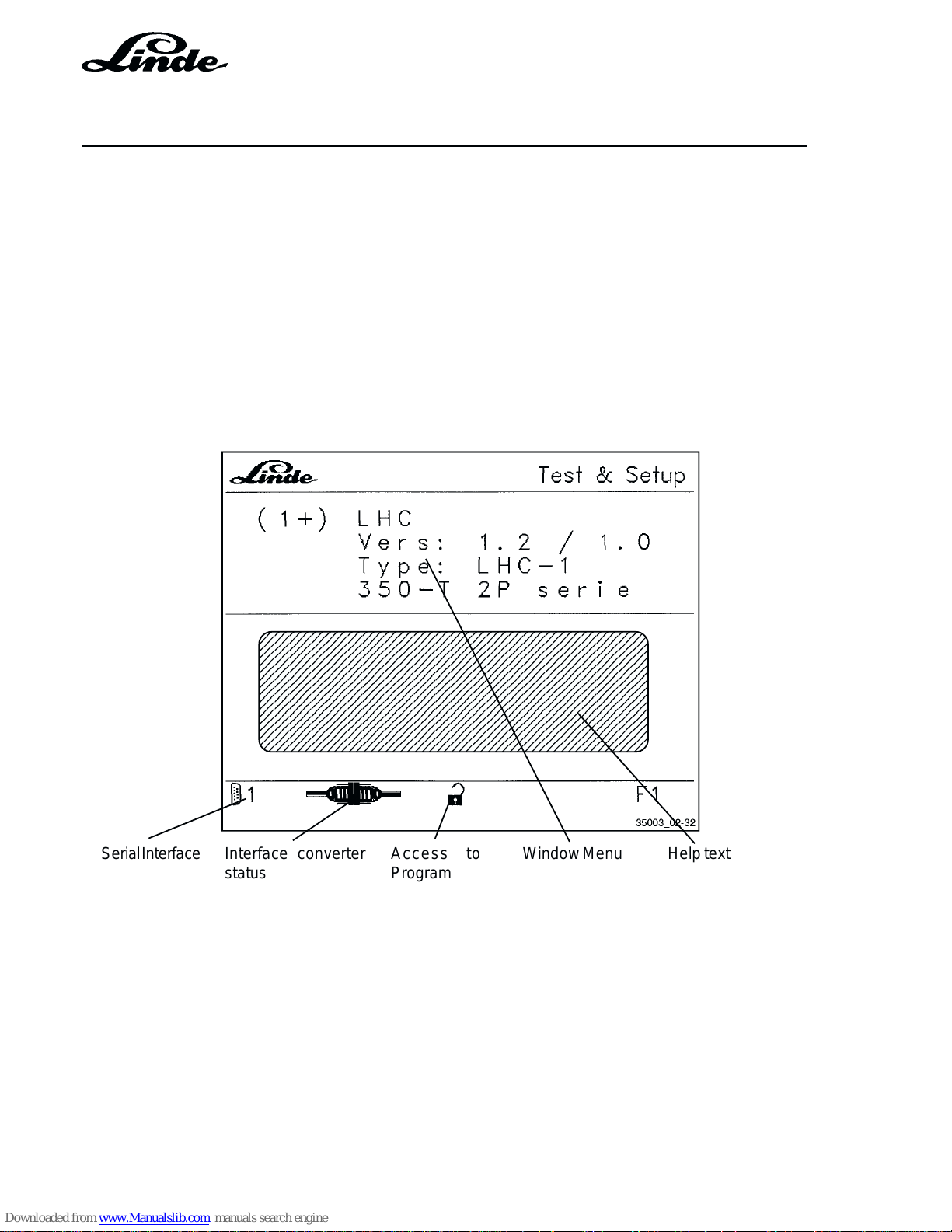
2.10.1.3 LINDE DIAGNOSTIC PROGRAM
Depending on the installed diagnostic program (master program or service program), different window
menus can be displayed. The service program permits the same menus as in the Linde diagnostic module
to be displayed. The Master program (identified by M) permits additional menus to be displayed. Information
on the diagnostic program installed on the computer is displayed at the bottom of the computer window.
After starting the diagnostic program and turning on the truck key switch, a beep tone is heard and the main
window appears on the computer monitor.
The main window can be divided into an upper window and a lower window area. The upper window displays
the window menu, which is identical to the menu on the diagnostic module.
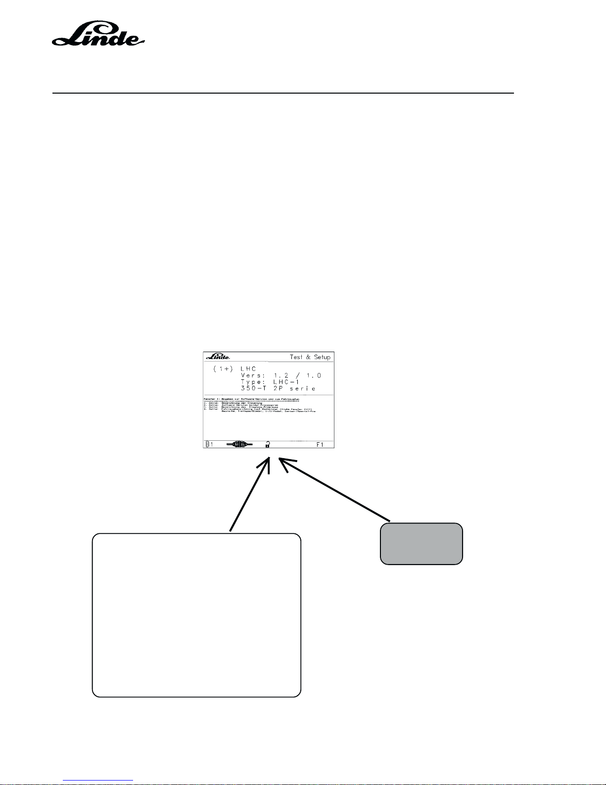
The lower window displays text which is different for every window. This text contains clarifying information.
SERIAL INTERFACE
This symbol displays the active serial interface (COM1 or COM2).
Interface converter
status
Serial Interface Help textWindow MenuAccess to
Program
Page 63

Section 2
Page 37
Service Training
H01 / Chapter 1
350 804 4701.0201
02.01
INTERFACE CONVERTER STATUS
This symbol, two connectors, appears to the right of the serial interface symbol at the bottom of the computer
window. When the interface converter is correctly installed and correctly operating, the two plugs are together
and green in colour. If the two connectors are open and red in colour, a problem exists with the data transfer
(false COM serial interface, the interface converter is incorrectly installed or the key switch is not turned on).
ACCESS TO PROGRAM
Key symbol Service program
Open lock symbol Master program (menu windows M can be displayed)
The diagnostic program works with menu windows. Each window shows different information about the truck.
The windows are called up by simply entering the window number, e.g. 1. When calling up a window with
two digits e.g. 72, simply quickly enter the two digits in the correct order. If you wish to change to another
window, enter the new window number. Depending on the software version for the controller, the following
windows can be displayed.
Window 1: Information on software version and truck type
M Window 11: Information on truck type code in the cable loom
M Window 12: Comparison of master and safety processor codes
Window 2: Current fault messages
Window 3: Stored fault messages
Window 31: Clearing fault messages in window 3 (up to including version 1.3)
Window 32: Stored fault messages (up to including version 1.3)
M Window 33: Clearing window 32 (up to including version 1.3)
Window 4: Inputs
M Window 41: Switch signals of both processors
Window 5: Outputs
M Window 51: Additional information on outputs
Window 6: Analogue values
M Window 61: Analogue values (master and safety processor) - potentiometer
M Window 62: Analogue values (master and safety processor) - potentiometer and pump
control solenoids.
Window 7: Setting truck speed and specified RPM
Window 71: Resetting parameters to standard factory settings
M Window 72: Seat switch
M Window 73: Resetting parameters of window 72 to standard factory settings
M Window 74: Maximum speed
M Window 75: Setting of initial inverse current and final pump current
M Window 76: Resetting parameters of window 75 to standard factory settings
Window 8: Zero adjustment of potentiometer (teach-in)
Page 64
Service Training
Section 2
Page 38
H01 / Chapter 1
350 804 4701.0400
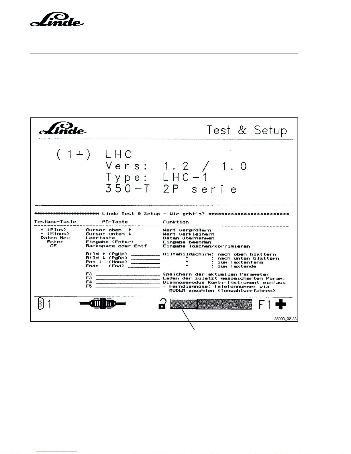
Scroll bar
2.10.1.3.1 HELP FUNCTION
When the F1 key is pressed a help text is displayed in the lower part of the computer window explaining the
meaning of the individual keys. Keys PgUp é and PgDn ê serve to scroll the help text. The text is selected
by using a scroll bar. Pressing the F1 key again switches the help function off and a text explaining the
respective window appears.
Page 65

Section 2
Page 39
Service Training
H01 / Chapter 1
350 804 4701.0400
The following table provides a summary of important keys on the Linde diagnostic module and PC.
FUNCTIONS OF THE KEYS
Module Key PC Key Function
+ (Plus) Cursor é up Increase value
- (Minus) Cursor ê down Decrease value
New data Tab bar Save data
Enter Enter (Return) End of input
CE Backspace or Del Correct or delete input
PgUp é Help function window: scroll up
PgDn ê Help function window: scroll down
Home Help function window: go to text beginning
End Help function window: go to text end
F1 Call up help function window
F2 Store the active parameter
F3 Call up the last stored parameter
F4 On/Off: combined instrument, diagnostic mode
F5 Long distance diagnostics: dial telephone number via modem
(tone dial mode) and make the connection
Long distance diagnostics: break the telephone connection
Shift F5 Long distance diagnostics: dial telephone number via modem
Same as F5 except use pulse dial mode
Long distance diagnostics: break the telephone connection
F9 Print the status and the parameter window displayed on the computer
monitor
ESC Break off (escape) a store, call up or print procedure
ALT x or ALT F4 End the program
Page 66
Service Training
Section 2
Page 40
H01 / Chapter 1
350 804 4701.0201
02.01
ERROR HANDLING
An error is detected as such by the processor only if it is applied for a minimum period (mostly 200 ms). In
this way, brief and non-critical error events due to signal noise or delays in the sensing elements are not taken
into consideration.
If an error is detected by the processor, the following occurs:
- The fault warning lamp flashes.
- Interventions are controlled by the microprocessor depending on the seriousness of the errors: truck
deceleration, RPM limitation, solenoids de-energised, etc.
- An error number describing the fault is stored in a non-volatile store (EEPROM).
- The error number can be read in the windows <2> and <3> of the diagnostic unit.
A troubleshooting with the diagnostic unit is possible at any time subsequently. The error number, stored
in the EEPROM when the fault occurred, can be displayed by selecting window <3> of the diagnostic unit.
In this way it is afterwards possible to identify unstable, sporadic or non-reproducible errors.
TEST CONDITION
The battery voltage should be at least 11.3 V.
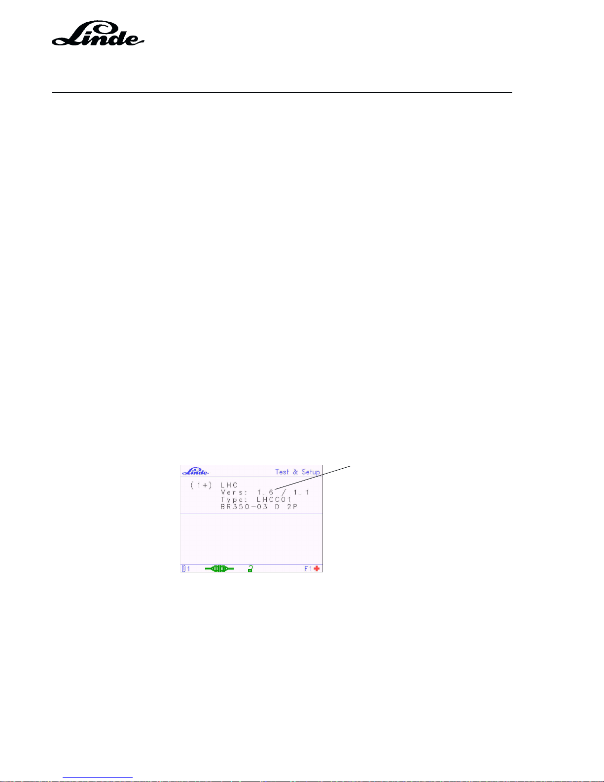
Before starting work on the LHC diagnostic program, identify the software version (shown in window 1).
Software version
(main processor)
Depending on the software version, select the diagnostics description as follows:
from 1.1 to 1.3 Section 2.10.1.3.2
from 1.4 and 1.5 Section 2.10.1.3.4
ab 1.6 Section 2.10.1.3.6
NOTE: The first step in the diagnosis should be to perform a calibration of the traction potentiometer
in window 8 of the respective software version.
All of the values given in the windows in the document are examples only.
Page 67

Section 2
Page 41
Service Training
H01 / Chapter 1
350 804 4701.0201
02.01
2.10.1.3.2 OVERVIEW OF MENU WINDOWS - LHC SOFTWARE VERSION 1.1 - 1.3
Service
Master
ð
ð
ð
ð
ð
ð
ðð
ð
ðð
1+
11+
12
23+
33
32+
31+
4+
41
5+
51
6+
61
7+
71+
73
72+
8
VERSION 1.1 - 1.3
Page 68
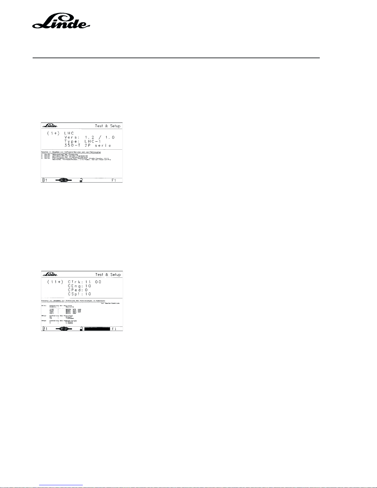
Service Training
Section 2
Page 42
H01 / Chapter 1
350 804 4701.0201
02.01
2.10.1.3.3 MENU WINDOWS IN DETAIL - LHC SOFTWARE VERSION 1.1 - 1.3
WINDOW 1 INFORMATION ON SOFTWARE VERSION AND TRUCK TYPE
ALL SOFTWARE VERSIONS
This window displays general information on the truck as detected by the Test Module.
1st line: Controller designation
2nd line: Software version of both processors
3rd line: Designation of diagnostic program
4th line: Truck model code:
(see window (11)) series, LPG/Diesel,
1/2 pedal(s), series/special truck
NOTE: If the information displayed in the window does not correspond to the truck version, there is a
fault in the wiring or the electronic controller.
WINDOW 11 (MASTER VERSION) INFORMATION ON TRUCK TYPE CODE IN THE CABLE
LOOM
CTrk Truck series code
1100 BR 350 H18, H20
0110 BR 351 H20, H25
1001 BR 351 H30, H35
0011 BR 352 H40
CEng Engine type code
01 Diesel
10 LPG
CPed: Pedal type code
0 2 pedals
1 1 pedal
VERSION 1.1 - 1.3
Page 69

Section 2
Page 43
Service Training
H01 / Chapter 1
350 804 4701.0201
02.01
CSpl Equipment code
01 Special truck
10 Series truck
WINDOW 12 (MASTERVERSION) COMPARISON OF MASTER AND SAFETY PROCESSOR
CODES
The signals are displayed in pairs (XY) with the following declaration:
X is the code read by the master processor
Y is the code read by the safety processor
In trouble-free operation X always equals Y, with both processors reading the same code.
CTrk XY XY
11 11 BR 350
00 11 BR 351 H20, H25
11 00 BR 351 H30, H35
00 00 BR 352
CEng XY
00 Diesel
11 LPG
CPed XY
00 Two-pedal
11 Single-pedal
CSpl XY
00 Special truck
11 Series truck
VERSION 1.1 - 1.3
Page 70
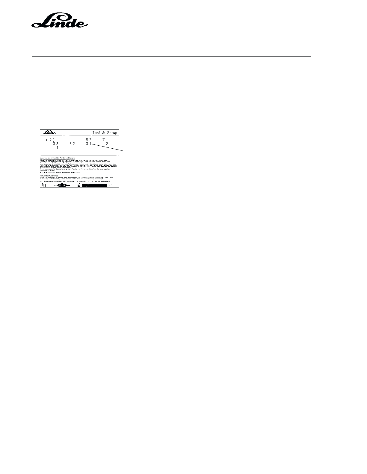
Service Training
Section 2
Page 44
H01 / Chapter 1
350 804 4701.0201
02.01
WINDOW 2 CURRENT STATUS MESSAGES AND FAULT MESSAGES
This window displays a message if driving is restricted or disabled for safety reasons. The messages are
displayed only as long as the restriction or problem exists. In case of faults the red warning lamp will flash;
in case of wrong driver commands such as depressing the brake pedal, the lamp will not illuminate.
The current truck status messages are displayed as a single-digit number, the fault message as a two-digit
number.
Example: (31) = Potentiometers 1 and 2 are incompatible
Example: 1 = Brake switch 1 operated
Example: 2 = Brake switch 2 operated
In the above example, brake switch 1 and 2 are operated, i.e. the engine can be started. Error 31 was
detected, i.e. potentiometers 1 and 2 are incompatible. When the brake pedal is released, the numbers 1
and 2 will disappear, whereas the fault number 31 will still be displayed. The engine can be therefore be
started, but the truck will not move off if an accelerator pedal is operated.
The meaning of the status and error numbers are listed in the following table.
The fault codes have the following meaning:
Status messages:
If none of the following status messages are shown in window 2, the
truck is operational if no other fault has been detected in the truck.
1 Brake pedal switch 1S5 operated (brake pedal is partially depressed)
2 Brake pedal switch S14 operated (brake pedal is depressed)
3 Brake pedal not yet depressed after turning on the ignition
4 Seat switch not operated
VERSION 1.1 - 1.3
Page 71

Section 2
Page 45
Service Training
H01 / Chapter 1
350 804 4701.0201
02.01
Fault messages:
The following reactions can be witnessed on the truck when a fault occurs:
W Warning lamp flashing
K Truck drives at creep speed
B Truck brakes to a standstill or remains stationary if not yet moving
R Current only achieves start of pump control
E All power stages without power
L Engine goes to low idling speed
F Release magnet de-energised, truck braking with brake jets (restrictors)
S Safety relay in the controller de-energised, all power stages without power
Truck responses
19 No calibration new LHC controller in truck
not yet calibrated
20 Invalid truck code maybe cable loom WELFS
21 Invalid engine type code maybe cable loom WELFS
22 Invalid series code maybe cable loom WELFS
23 Invalid series/special truck code maybe cable loom WELFS
31 Both pot signals do not match,
and neither is 0 V incompatible WBL
32 UPot1 too low or too high out of range W BL
33 UPot2 too low or too high out of range W BL
34 Both pot signals at 0 V too low
35 Inadmissible pedal code and not all inputs are open WBL
36 Inadmissible pedal code and all inputs are open
37 Both inputs of the brake microswitch
have the same status same status W B
38 Brake switch S14 switching before 1S5 WB
39 Both inputs of the seat microswitch
have the same status same status WB L
41 10 V power supply is too low (< 8 V) whereas
battery voltage is too high (> 11 V)
43 Power stage supply interrupted
(eg fuse blown, relay oxidized)
44 Power supply can not be cut out by relay
(relay sticking, final relay stage leaky)
45 Release power stage not conducting or
output shorted against (-) unequal WB
46 Release power stage fused or
output shorted against (-)
47 Release magnet resistance too high
51 Engine control element resistance too low or
power stage leaky too high WELFS
52 Engine control element resistance too high or
power stage defective or magnet shorted against (-) WELFS
53 Pump control element V resistance too low or
power stage leaky too high WELFS
VERSION 1.1 - 1.3
Page 72

Service Training
Section 2
Page 46
H01 / Chapter 1
350 804 4701.0201
02.01
54 Pump control element V resistance too high or
power stage defective or magnet shorted against (-) WELFS
55 Pump control element R resistance too low or
power stage leaky too high WELFS
56 Pump control element R resistance too high or
power stage defective or magnet shorted against (-) WELFS
57 Gas shutoff valve resistance too low or
power stage leaky (LP-gas only) too high
58 Gas shutoff valve resistance too high or
power stage defective or magnet shorted against (-)
(LP-gas only)
59 Release valve: drive and feedback (status) unequal WB
61 Speed signal too high W
62 Jump of RPM signal from over 800 rpm
to 0 rpm (cable broken)
65 Tilt pressure signal 1S1 6 bar with engine stationary W
66 Lift pressure signal 1S2 14 bar with engine stationary W
67 Signal 1S2 no signal 1S1 (14 bar without 6 bar) W
Master processor: monitoring of safety processor:
71 Safety processor not releasing WELFS
72 Pot signals both processors incompatible W
73 Pot 1B2.1 out of range W
74 Input signals of both processors incompatible W
75 Serial data transfer inactive W
76 Serial data transfer inactive W
Safety processor: self-monitoring:
80 Invalid series code maybe cable loom FS
81 Invalid 1-/2-pedal code maybe cable loom FS
82 Accelerator pedal: signal 1B2.1 out of range FS
83 Built-in test detected release valve not OK FS
84 Built-in test detected safety relay not OK FS
85 Pump forward and reverse current simultaneously FS
86 Pump forward current with specified value of pot = 0 FS
87 Pump reverse current with specified value of pot = 0 FS
88 Pump forward current too high FS
89 Pump reverse current too high FS
90 Stimuli for Bosch test not OK FS
91 Stimuli for Linde test not OK FS
99 Internal fault in safety processor FS
VERSION 1.1 - 1.3
Page 73
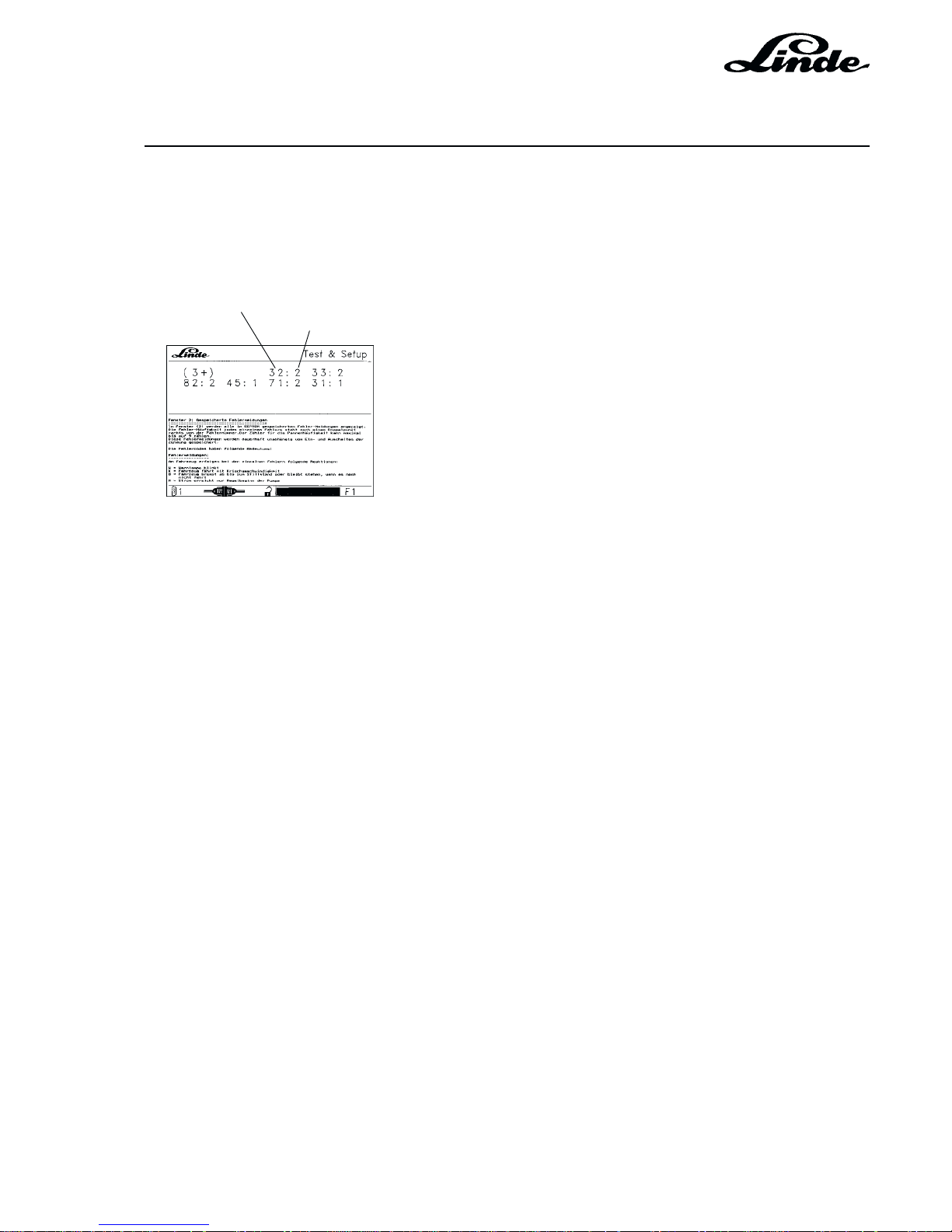
Section 2
Page 47
Service Training
H01 / Chapter 1
350 804 4701.0201
02.01
WINDOW 3 STORED FAULT MESSAGES
Window (3) displays all the fault messages stored in the EEPROM. The frequency of each fault is indicated
to the right of a colon behind the fault number. The fault counter can only count to 9 maximum.
These fault messages are stored permanently independent of turning the ignition on and off.
Fault number
Fault frequency
The fault codes have the following meaning:
Fault messages:
The following reactions can occur on the truck with individual faults:
W Warning lamp flashing
K Truck driving at creep speed
B Truck brakes to a full stop or remains stationary when not moving
R Current achieves only start of pump control
E All power stages are without power
L engine goes to low idling speed
F Release magnet de-energised, truck braking with brake jets (restrictors)
S Safety relay in the controller de-energised, all power stages without power
Reactions on the truck
20 Invalid truck code maybe cable loom WELFS
21 Invalid engine type code maybe cable loom WELFS
22 Invalid series code maybe cable loom WELFS
23 Invalid Series/special truck code maybe cable loom WELFS
31 Accelerator pedal: pot 1B2.1 and pot 1B2.2 incompatible WBL
32 Accelerator pedal: signal from pot 1B2.1 out of range WBL
33 Accelerator pedal: signal from pot 1B2.2 out of range WBL
34 Accelerator pedal: pot supply voltage too low
35 1-/2-pedal: invalid combination of direction signals WBL
VERSION 1.1 - 1.3
Page 74

Service Training
Section 2
Page 48
H01 / Chapter 1
350 804 4701.0201
02.01
37 Brake switch 1S5 breaker/maker same status WB
38 Brake switch S14 switching before 1S5 WB
39 Seat switch 1S8 breaker/maker same status WB L
43 Safety relay: drive/feedback unequal
45 Release valve: drive and feedback unequal W B
51 Engine magnet: current too high WELFS
52 Engine magnet: open circuit WELFS
53 Magnet for pump forward 1Y2: current too high WELFS
54 Magnet for pump forward 1Y2: open circuit WELFS
55 Magnet for pump reverse 1Y3: current too high WELFS
56 Magnet for pump reverse 1Y3: open circuit WELFS
57 Magnet for working hydraulics: current too high
58 Magnet for working hydraulics: open circuit
59 Release valve: drive and feedback (status) unequal WB
61 RPM signal too high W
65 Tilt pressure signal 1S1 6 bar with engine stationary W
66 Lift pressure signal 1S2 14 bar with engine stationary W
67 Signal 1S2 without signal 1S1 (14 bar without 6 bar) W
Master processor: monitoring of safety processor:
71 Safety processor not releasing WELFS
72 Potentiometer signals of both processors incompatible W
73 Pot 1B2.1 out of range W
74 Input signals of both processors incompatible W
75 Serial data transfer inactive W
76 Serial data transfer inactive W
Safety processor: self monitoring:
80 Invalid series code maybe cable loom FS
81 Invalid 1-/2-pedal code maybe cable loom FS
82 Accelerator pedal: signal 1B2.1 out of range FS
83 Built-in test detected release valve not OK FS
84 Built-in test detected safety relay not OK FS
85 Pump forward and reverse current simultaneously FS
86 Pump forward current with pot setting = 0 FS
87 Pump reverse current with pot setting = 0 FS
88 Pump forward current too high FS
89 Pump reverse current too high FS
90 Stimuli for Bosch test not OK FS
91 Stimuli for Linde test not OK FS
99 Internal fault in safety processor FS
VERSION 1.1 - 1.3
Page 75
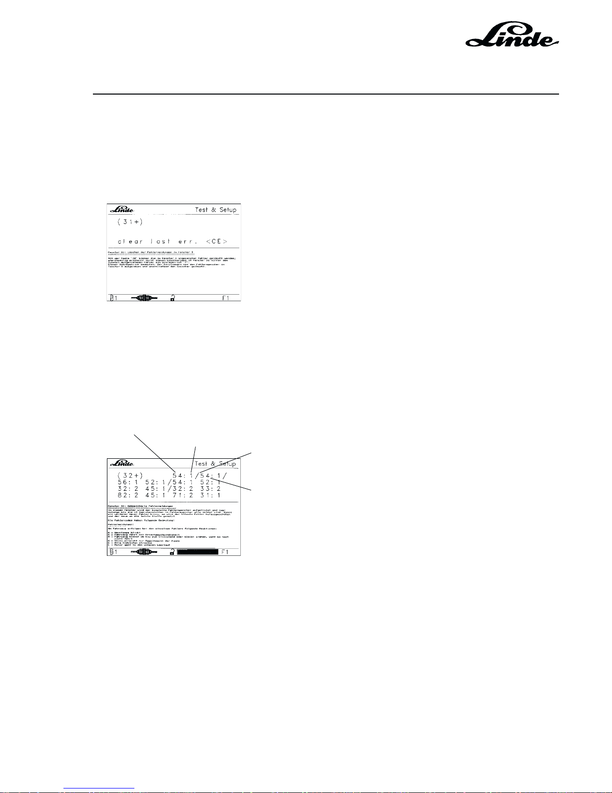
Section 2
Page 49
Service Training
H01 / Chapter 1
350 804 4701.0201
02.01
WINDOW 31 CLEARING THE FAULT MESSAGES IN WINDOW 3
With the CE key it is possible to clear the faults shown in window 3; at the same time a slash "/" appears
in window 32 behind the last fault after clearing.
This slash means: The service engineer has read the faults stored in memory in window 3 and then cleared
the memory.
WINDOW 32 STORED FAULT MESSAGES
In window 32 (press key 3 and 2) the faults remain stored. The controller will set a slash at the end of the
fault codes and all malfunctions occurring thereafter will be shown again behind the slash.
Fault number
Fault frequency
Sign showing fault was acknowledged by service engineer
Fault number and frequency of occurrence after acknowledgement
If a memory overflow occurs, the earliest stored faults will be deleted. The maximum number of faults that
can be indicated is 9. If the frequency indicated is 9 this means that the fault can have occurred over 9 times.
A repetitive fault is incremented each time the ignition switch is turned on.
In the example fault 32 was detected two times. Then the service engineer acknowledged the fault. The fault
occurred again twice subsequently.
VERSION 1.1 - 1.3
Page 76

Service Training
Section 2
Page 50
H01 / Chapter 1
350 804 4701.0201
02.01
The fault codes have the following meaning:
Fault messages:
The following truck responses can occur with individual faults:
W Warning lamp flashing
K Truck driving at creep speed
B Truck brakes to a full stop or remains stationary when not moving
R Current achieves only start of pump control
E All power stages are without power
L engine goes to low idling speed
F Release magnet de-energised, truck braking with brake jets (restrictors)
S Safety relay in the controller de-energised, all power stages without power
Reactions on the truck
20 Invalid truck code maybe cable loom WELFS
21 Invalid engine type code maybe cable loom WELFS
22 Invalid series code maybe cable loom WELFS
23 Invalid series/special truck code maybe cable loom WELFS
31 Accelerator pedal: pot 1B2.1 and pot 1B2.2 incompatible WBL
32 Accelerator pedal: signal from pot 1B2.1 out of range WBL
33 Accelerator pedal: signal from pot 1B2.2 out of range WBL
34 Accelerator pedal: pot supply voltage too low
35 1-/2-pedal: inadm. combination of direction signals WBL
37 Brake switch 1S5 breaker/maker same status WB
38 Brake switch S14 switching before 1S5 WB
39 Seat switch 1S8 breaker/maker same status WBL
43 Safety relay: drive/feedback unequal
45 Release valve: drive and feedback unequal WB
51 Engine magnet: current too high WELFS
52 Engine magnet: open circuit WELFS
53 Magnet for pump forward 1Y2: current too high WELFS
54 Magnet for pump forward 1Y2: open circuit WELFS
55 Magnet for pump reverse 1Y3: current too high WELFS
56 Magnet for pump reverse 1Y3: open circuit WELFS
57 Working hydraulics magnet: current too high
58 Working hydraulics magnet: open circuit
59 Release valve: drive and feedback (status) unequal WB
61 Speed signal too high W
65 Tilt pressure signal 1S1 6 bar with engine stationary W
66 Lift pressure signal 1S2 14 bar with engine stationary W
67 Signal 1S2 without signal 1S1 (14 bar without 6 bar) W
VERSION 1.1 - 1.3
Page 77
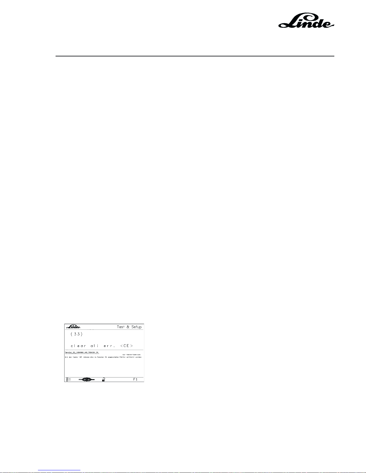
Section 2
Page 51
Service Training
H01 / Chapter 1
350 804 4701.0201
02.01
Master processor: monitoring of safety processors:
71 Safety processor not releasing WELFS
72 Potentiometer signals of both processors incompatible W
73 Pot 1B2.1 out of range W
74 Input signals of both processors incompatible W
75 Serial data transfer inactive W
76 Serial data transfer inactive W
Safety processor: self monitoring:
80 Invalid series code maybe cable loom FS
81 Invalid 1-/2-pedal code maybe cable loom FS
82 Accelerator pedal: signal 1B2.1 out of range FS
83 Built-in test detected release valve not OK F S
84 Built-in test detected safety relay not OK FS
85 Pump forward and reverse current simultaneously F S
86 Pump forward current with pot setting = 0 FS
87 Pump reverse current with pot setting = 0 FS
88 Pump forward current too high FS
89 Pump reverse current too high FS
90 Stimuli for Bosch test not OK FS
91 Stimuli for Linde test not OK FS
99 Internal fault in safety processor FS
WINDOW 33 (MASTER VERSION) CLEARING WINDOW 32
The faults displayed in window 32 can be cleared with the CE key.
VERSION 1.1 - 1.3
Page 78
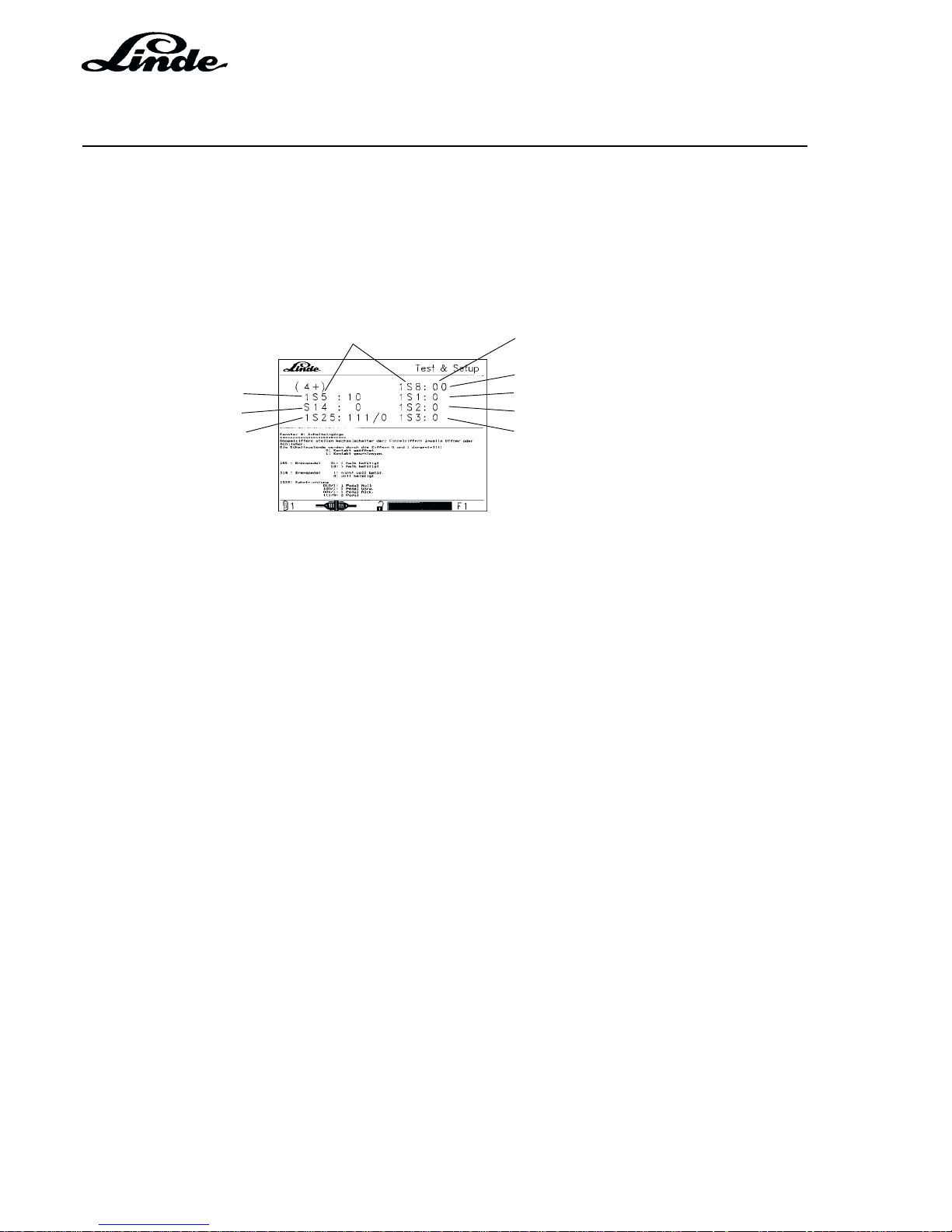
Service Training
Section 2
Page 52
H01 / Chapter 1
350 804 4701.0201
02.01
WINDOW 4 INPUTS
The switch input signals are displayed in window 4.
The switches are numbered and carry the same designation as in the current path diagram. The status of
single switches is indicated behind the switch number; for selective switches the status of both channels is
displayed.
Switches Switching states
Seat switch
Brake pedal switch 1 Pressure switch 6 bar
Brake pedal switch 2 Pressure switch 14 bar
Directional switch Auxiliary hydraulics
Double digits represent selective switches, single digits either a breaker or maker.
The switching states are indicated by the digits 0 and 1:
0: contact open
1: contact closed
1S5 Brake pedal 01: < half operated
10: > half operated
S14 Brake pedal 1: not fully operated
0: fully operated
1S25 Travel direction 010/1: 1-pedal at zero position
100/1: 1-pedal forward
001/1: 1-pedal reverse
111/0: 2-pedal
NOTE: The 4 signals from 1S25 are either provided by the single-pedal lever or by the encoded plug
for double-pedal.
1S8 Seat switch 11: not connected (cable connected)
01: not operated
10: operated
00: not connected (cable open)
1S1 Tilt pressure 0: < 6 bar
1: > 6 bar
VERSION 1.1 - 1.3
Page 79
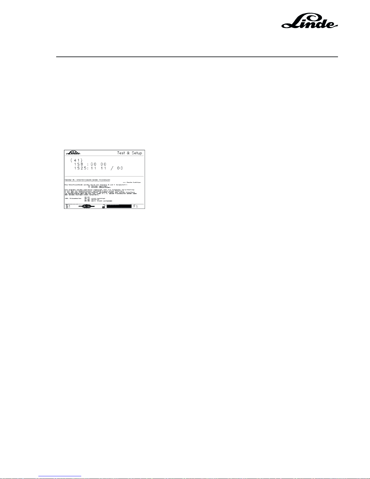
Section 2
Page 53
Service Training
H01 / Chapter 1
350 804 4701.0201
02.01
1S2 Lift pressure 0: < 14 bar
1: > 14 bar
1S3 Aux. hydraulics 0: not operated or not connected
1: operated
WINDOW 41 (MASTER VERSION) SWITCH SIGNALS OF BOTH PROCESSORS
The switching states are indicated by the digits 0 and 1:
0: contact open
1: contact closed
The signals are displayed in pairs (XY) with following declaration:
X is the switch signal read by the master processor
Y is the signal of the same switch read by the safety processor
During faultless operation X always equals Y, with both processors seeing the same status of a switch.
1S8 Seat switch XY XY
00 11 not operated
11 00 operated
00 00 possibly not present
1S25 Travel direction XY XY XY
00 00 / 11: 1-pedal at zero position
11 00 / 11: 1-pedal forward
00 11 / 11: 1-pedal reverse
11 11 / 00: 2-pedal
VERSION 1.1 - 1.3
Page 80
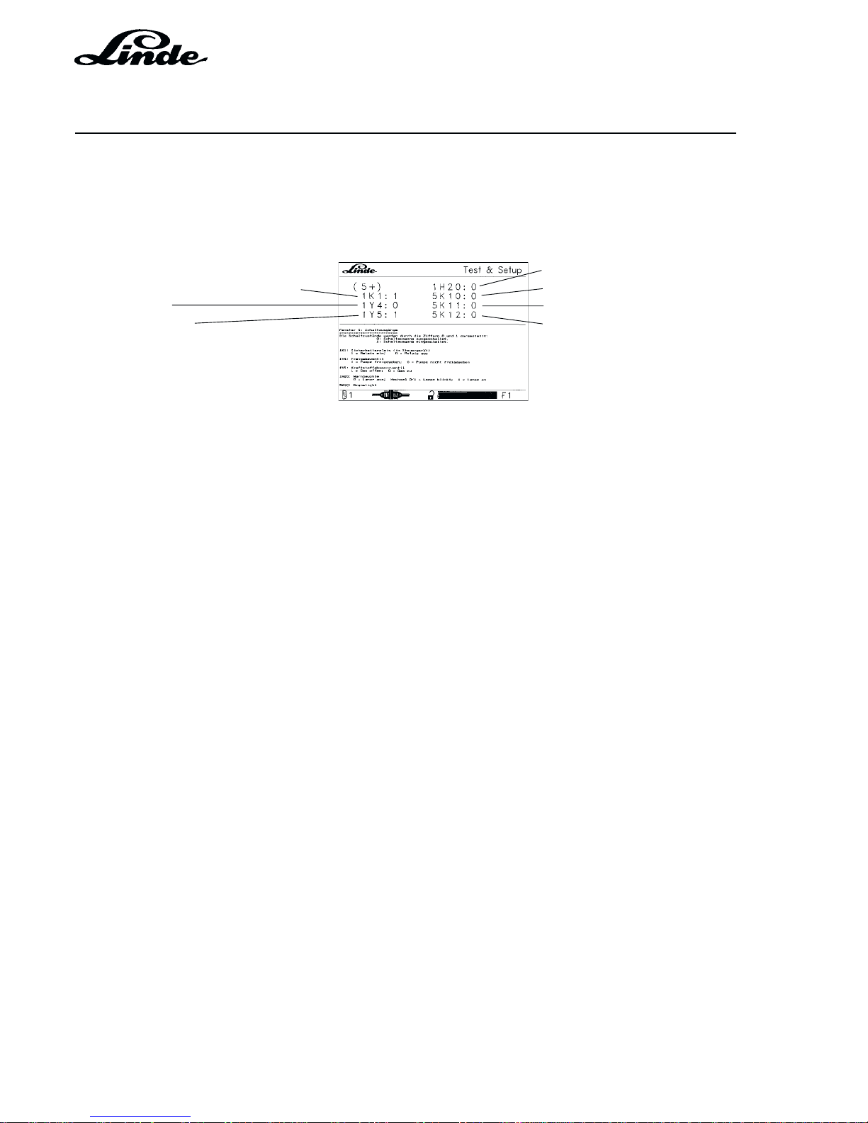
Service Training
Section 2
Page 54
H01 / Chapter 1
350 804 4701.0201
02.01
WINDOW 5 OUTPUT SIGNALS
Window 5 displays the output signals. The indicated components are numbered and correspond to the
designation in the wiring diagram.
Fault lamps
Safety relay in electronic controller Stop light
Release valve Flashing light during reversing
Fuel shutoff valve Reversing light
REPRESENTATION OF SWITCHING STATES
0 means not driven
1 means driven
1K1 Safety relay in electronic controller
1K1:1 appears after the ignition is turned on.
1Y4 Release valve
Depress the accelerator pedal with the engine running and the brake released. Output 1Y4:1 will be
displayed.
1Y5 Fuel shutoff valve
During the starting procedure the output changes from 1Y5:0 to 1Y5:1.
1H20 Fault lamps
With the ignition on, lamps on: 1H20:1
With the engine running, lamps off: 1H20:0
With malfunction, lamps flashing: alternately 1H20:0/1
5K10 Stop light
5K10:0 Stop light off
5K10:1 Stop light on
VERSION 1.1 - 1.3
Page 81
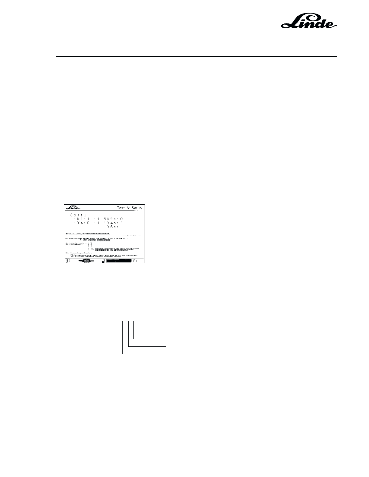
Section 2
Page 55
Service Training
H01 / Chapter 1
350 804 4701.0201
02.01
5K11 Flashing light during reversing
5K11:0 Flashing light off
5K11:0/1 Flashing light on alternately
5K12 Reversing light
5K12:0 Light off
5K12:1 Light on
NOTE: Optional equipment can be connected via outputs 5K10, 11, and 12.
WINDOW 51 (MASTER VERSION) ADDITIONAL INFORMATION ON OUTPUTS
The switching states are indicated by the digits 0 and 1:
0: output off
1: output on
1K1 Safety relay X Y Z
1Y4 Release valve X Y Z
Power stage feedback to safety processor
Control signal from safety processor
Control signal from master processor
5K*s Status of lamp power stage
to *
For the outputs 5K10, 5K11, 5K12, 1H20 there is only one status signal which indicates the 4 outputs
mentioned above jointly. Depending upon the type of equipment on the truck, a different number of
outputs are used. The meaning of 5K*s is therefore that the status of 1 or 2 or 3 or 4 outputs is indicated
simultaneously.
VERSION 1.1 - 1.3
Page 82

Service Training
Section 2
Page 56
H01 / Chapter 1
350 804 4701.0201
02.01
1Y4s Status of release valve power stage
1Y5s Status of gas shutoff valve
NOTE: For 1Y5s status has the following meaning:
Input Status Output
Normal function 0 1 0
111
Open load 1 0 1
Overtemperature 1 0 1
VERSION 1.1 - 1.3
Page 83
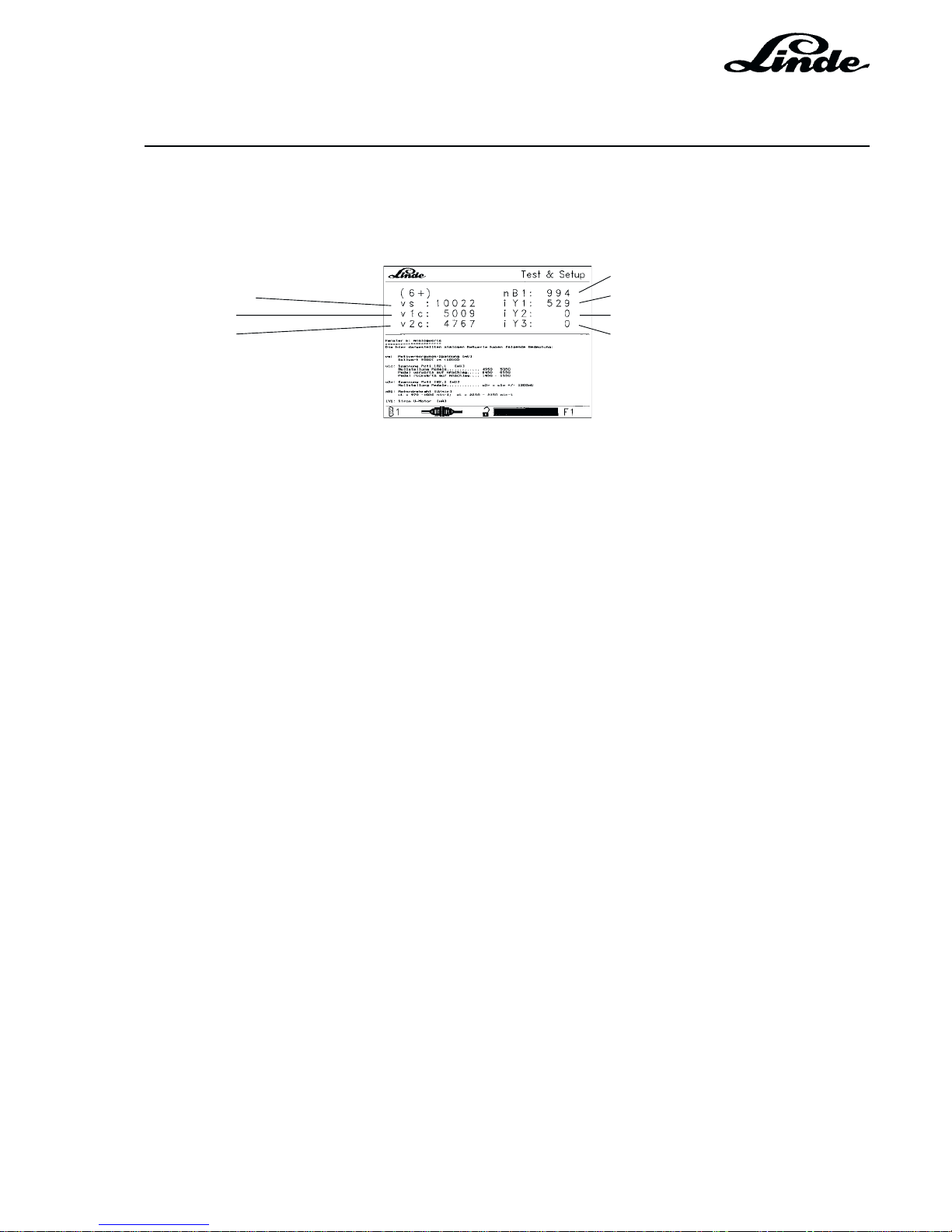
Section 2
Page 57
Service Training
H01 / Chapter 1
350 804 4701.0201
02.01
WINDOW 6 ANALOGUE SIGNALS
Window 6 displays the analogue values for the travel and RPM control.
Engine RPM
Supply voltage Current for engine operating magnet
Pot 1 value Pump forward current
Pot 2 value Pump reverse current
TEST CONDITIONS FOR MEASURING ANALOGUE VALUES VS - V1C AND V2C
- Accelerator pedal in neutral position
- Brake pedal released
- Ignition on
- Battery voltage > 11.3 V
vs Power supply 10 V
The voltage is provided by the electronic controller voltage regulator. The specified value is 9,500 10,500 mV and it is indicated under vs.
If the value is out of range, the controller assembly must be replaced.
v1c Corrected value of potentiometer 1 (1B2.1)
After the zero adjustment of potentiometer 1B2 (see window 8), the following values are shown under
v1c:
Accelerator pedals released: 4950 - 5050
Accelerator pedals max. forward: 8450 - 8550
Accelerator pedals max. reverse: 1450 - 1550
NOTE: Set the maximum forward and reverse values with the appropriate pedal screw.
v2c Corrected value of potentiometer 2 (1B2.2)
The following values must be shown for v2c
Zero position of pedals v2c = v1c ± 600 mV (read u1c in window 8)
NOTE: Replace potentiometer 1B2 if the values for v2c are out of range.
VERSION 1.1 - 1.3
Page 84

Service Training
Section 2
Page 58
H01 / Chapter 1
350 804 4701.0201
02.01
TEST CONDITIONS FOR MEASURING VALUES NB1 (ENGINE RPM) AND IY1 (OPERATING MAGNET)
- Accelerator pedals released
- Brake pedal depressed
- Engine idling
nB1 Engine RPM
Low idling speed: 970 - 1030 rpm
Maximum RPM with
accelerator fully depressed: 2250 - 2350 rpm
iY1 Current of engine operating magnet
Depending on the position of the accelerator pedals and engine load: i
max
= 1800 mA
NOTE: The maximum values of nB1 and iY1 are set in the electronic controller as fixed
parameters.
To measure iY1 and iY2, release the brake pedal.
iY2 Pump forward current
Depress forward pedal
until traction wheels
start rotating i = 440 - 460 mA
Depress forward
pedal fully i = max 1180 mA
iY3 Pump reverse current
Depress reverse pedal
until traction wheels
start rotating i = 440 - 460 mA
Depress reverse
pedal fully i = max 1180 mA
NOTE: If the current is out of range when the traction wheels begin to rotate, the start of control
on the hydraulic remote control must be adjusted.
The maximum value is specified in the electronic controller as a fixed value.
VERSION 1.1 - 1.3
Page 85
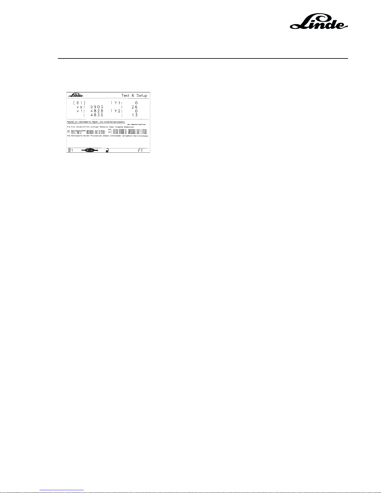
Section 2
Page 59
Service Training
H01 / Chapter 1
350 804 4701.0201
02.01
WINDOW 61 (MASTER VERSION) ANALOGUE VALUES (MASTER AND SAFETY
PROCESSOR)
The analogue readings shown here have the following meaning:
vs: Pot power supply read by 2nd processor
v1: Pot 1B2.1 read by 1st processor
iY1: Pump forward current read by 1st processor
iY2: Pump reverse current read by 1st processor
The analogue readings of both processors must correspond as much as possible.
VERSION 1.1 - 1.3
Page 86
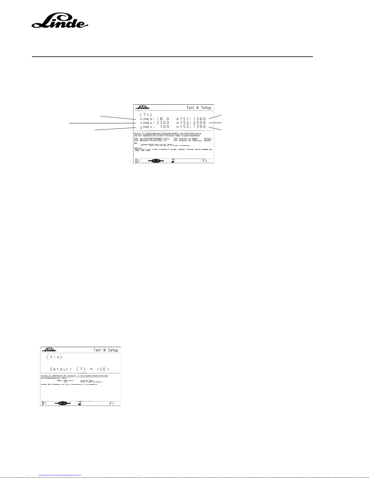
Service Training
Section 2
Page 60
H01 / Chapter 1
350 804 4701.0201
02.01
WINDOW 7 SETTING TRUCK SPEED AND SPECIFIED RPM
This window displays the parameters specified by the controller. These parameters can be modified up to
certain limits.
Maximum speed in km/h Tilting RPM, switch 6 bar
Engine RPM Lifting RPM, switch 14 bar
swashplate angle in % Auxiliary hydraulics RPM
(option)
HOW TO CHANGE THE PARAMETERS
- Press the ENTER button.
- The cursor will appear and jump to the first parameter.
- The value can be changed within limits using the “+” and “-” buttons.
- The modification is stored instantly and is in effect.
- Go to the next parameter by pressing ENTER again.
- The entry of parameters can be ended by selecting a different window number.
NOTE: V
max
can only be modified by changing n
max
(engine RPM) or g
max
(pump swashplate angle).
The speed is changed in steps of 50 RPM.
A change of n
max
is only effective if the brake pedal is released and the accelerator pedal fully
depressed.
The speed of n1S1 and n1S2 can be changed in steps of 100 RPM.
WINDOW 71 RESETTING PARAMETERS TO STANDARD FACTORY SETTINGS
Pressing 71 (7 and 1) quickly displays window 71 (sub-window of 7).
In window 71 the parameters shown in window 7 can be reset to their factory default settings.
The parameters are reset to their factory default settings by pressing the CE key.
VERSION 1.1 - 1.3
Page 87
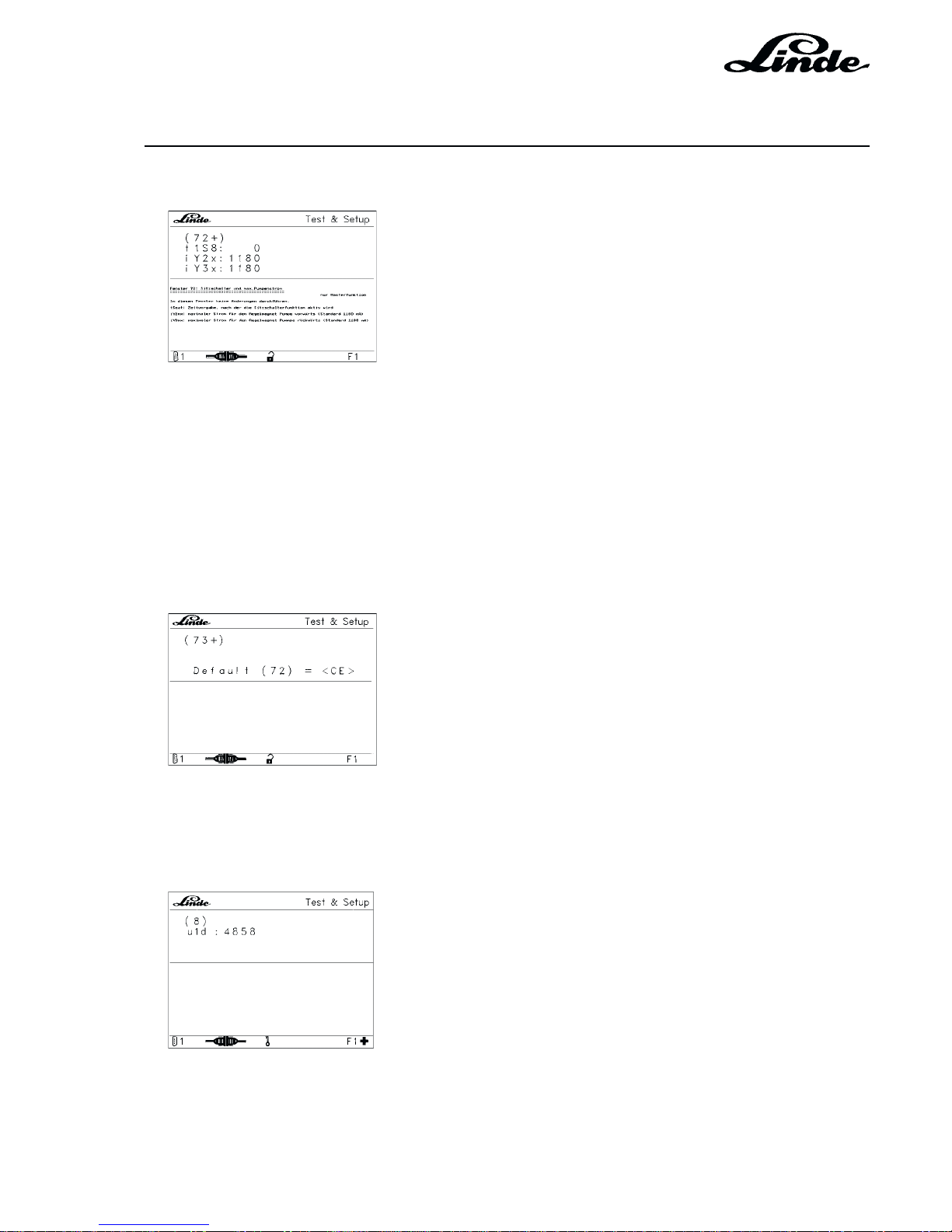
Section 2
Page 61
Service Training
H01 / Chapter 1
350 804 4701.0201
02.01
WINDOW 72 (MASTER VERSION) SEAT SWITCH AND MAXIMUM PUMP CURRENT
t1S8 Specified time after which the seat switch function becomes active
iY2x Maximum current for the pump forward control magnet (standard 1180 mA)
iY3x Maximum current for the pump reverse control magnet (standard 1180 mA)
WINDOW 73 (MASTER VERSION) RESETTING PARAMETERS IN WINDOW 72 TO STANDARD
FACTORY SETTINGS
The parameters are reset by pressing the <CE> key.
WINDOW 8 ABGLEICH DES FAHRPOTENTIOMETERS
u1d: Potentiometeristwert in mV (approx. 5000 ± 10 %), abgleichbar as longs as "OK" is displayed
For the calibration of the traction potentiometer, the brake pedal must be depressed and the ignition
switched on. The calibration is then confirmed by pressing the <ENTER> key.
VERSION 1.1 - 1.3
Page 88

Service Training
Section 2
Page 62
H01 / Chapter 1
350 804 4701.0201
02.01
2.10.1.3.4 OVERVIEW OF MENU WINDOWS - LHC SOFTWARE VERSION 1.4 AND 1.5
Service
Master
ð
ð
ð
ð
ð
ð
ðð
ð
ð
1+
11+
12
23+
32
31+
4+
41
5+
51
6+
61
7+
71+
73+
72+
8
ð
ðð
74+
76
75+
ð
62
VERSION 1.4 AND 1.5
Page 89
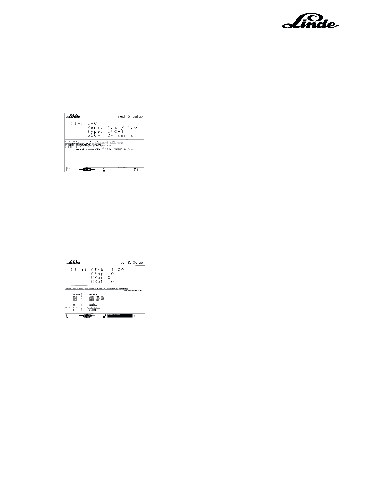
Section 2
Page 63
Service Training
H01 / Chapter 1
350 804 4701.0201
02.01
2.10.1.3.5 MENU WINDOWS IN DETAIL - LHC SOFTWARE VERSION 1.4 AND 1.5
WINDOW 1 INFORMATION ON SOFTWARE VERSION AND TRUCK TYPE
This window displays general information on the truck as detected by the Test Module.
1st line: Controller designation
2nd line: Software version of both processors
3rd line: Designation of diagnostic program
4th line: Truck model code:
(see window (11)) series, LPG/Diesel,
1/2 pedal(s), series/special truck
NOTE: If the information displayed in the window does not correspond to the truck version, there is a
fault in the wiring or the electronic controller.
WINDOW 11 (MASTER VERSION) INFORMATION ON TRUCK TYPE CODE IN THE CABLE
LOOM
CTrk Truck series code
1100 BR 350 H18, H20
0110 BR 351 H20, H25
1001 BR 351 H30, H35
0011 BR 352 H40
CEng Engine type code
01 Diesel
10 LPG
CPed: Pedal type code
0 2 pedals
1 1 pedal
VERSION 1.4 AND 1.5
Page 90
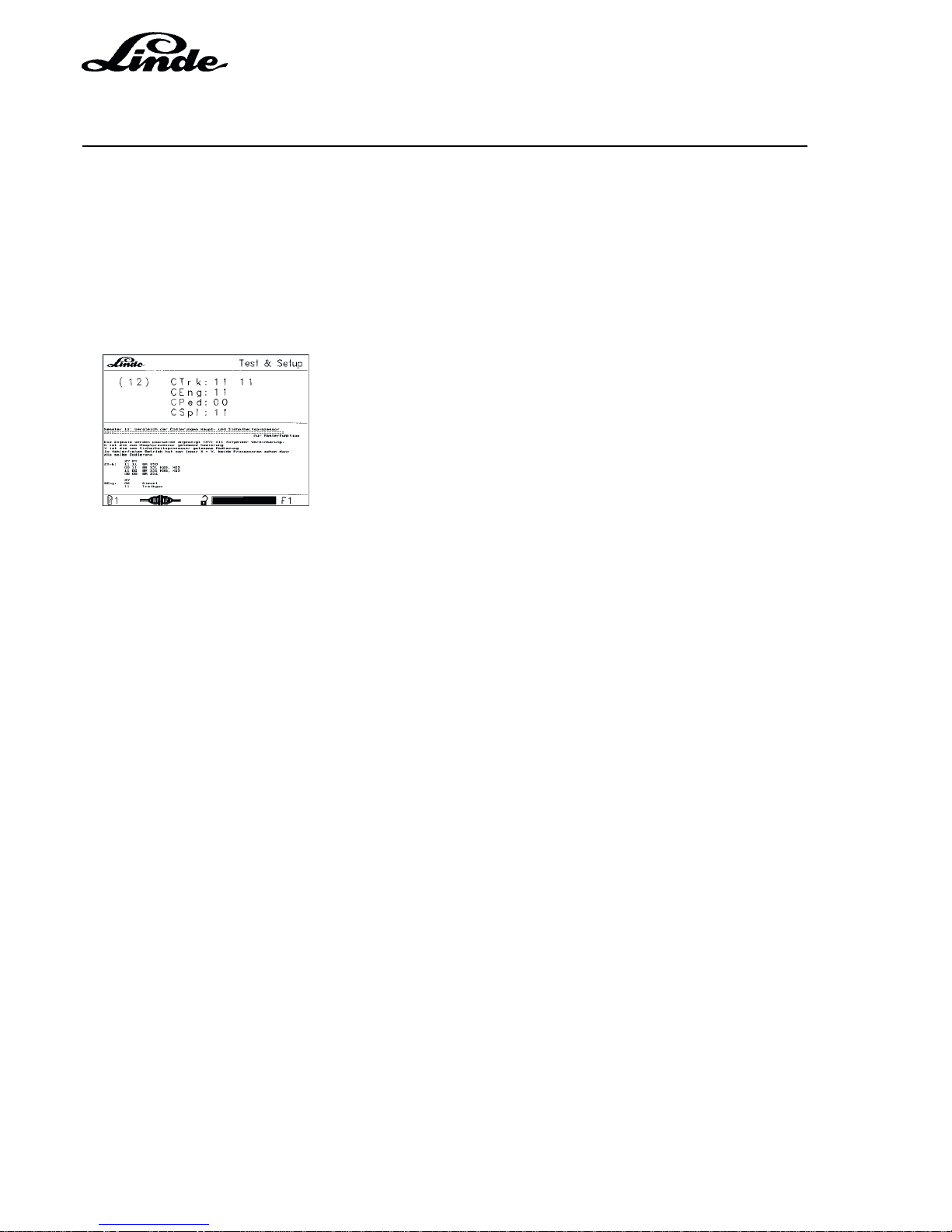
Service Training
Section 2
Page 64
H01 / Chapter 1
350 804 4701.0201
02.01
CSpl Equipment code
01 Special truck
10 Series truck
WINDOW 12 (MASTERVERSION) COMPARISON OF MASTER AND SAFETY PROCESSOR
CODES
The signals are displayed in pairs (XY) with the following declaration:
X is the code read by the master processor
Y is the code read by the safety processor
In trouble-free operation X always equals Y, with both processors reading the same code.
CTrk XY XY
11 11 BR 350
00 11 BR 351 H20, H25
11 00 BR 351 H30, H35
00 00 BR 352
CEng XY
00 Diesel
11 LPG
CPed XY
00 Two-pedal
11 Single-pedal
CSpl XY
00 Special truck
11 Series truck
VERSION 1.4 AND 1.5
Page 91
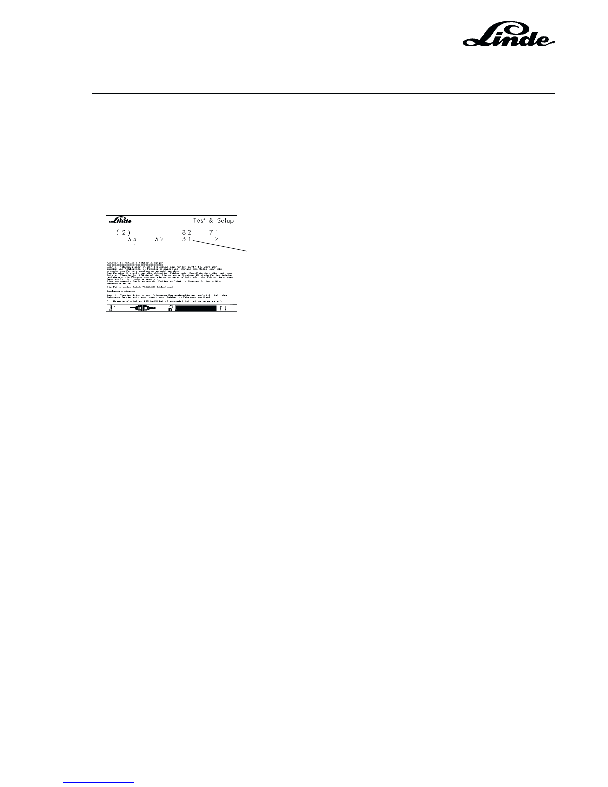
Section 2
Page 65
Service Training
H01 / Chapter 1
350 804 4701.0201
02.01
WINDOW 2 CURRENT STATUS MESSAGES AND FAULT MESSAGES
This window displays a message if driving is restricted or disabled for safety reasons. The messages are
displayed only as long as the restriction or problem exists. In case of faults the red warning lamp will flash;
in case of wrong driver commands such as depressing the brake pedal, the lamp will not illuminate.
The current truck status messages are displayed as a single-digit number, the fault message as a two-digit
number.
Example: (31) = Potentiometers 1 and 2 are incompatible
Example: 1 = Brake switch 1 operated
Example: 2 = Brake switch 2 operated
In the above example, brake switch 1 and 2 are operated, i.e. the engine can be started. Error 31 was
detected, i.e. potentiometers 1 and 2 are incompatible. When the brake pedal is released, the numbers 1
and 2 will disappear, whereas the fault number 31 will still be displayed. The engine can be therefore be
started, but the truck will not move off if an accelerator pedal is operated.
The meaning of the status and error numbers are listed in the following table.
The fault codes have the following meaning:
Status messages:
If none of the following status messages are shown in window 2, the
truck is operational if no other fault has been detected in the truck.
1 Brake pedal switch 1S5 operated (brake pedal is partially depressed)
2 Brake pedal switch S14 operated (brake pedal is depressed)
3 Brake pedal not yet depressed after turning on the ignition
4 Seat switch not operated
VERSION 1.4 AND 1.5
Page 92

Service Training
Section 2
Page 66
H01 / Chapter 1
350 804 4701.0201
02.01
Fault messages:
The following reactions can be witnessed on the truck when a fault occurs:
W Warning lamp flashing
K Truck drives at creep speed
B Truck brakes to a standstill or remains stationary if not yet moving
R Current only achieves start of pump control
E All power stages without power
L Engine goes to low idling speed
F Release magnet de-energised, truck braking with brake jets (restrictors)
S Safety relay in the controller de-energised, all power stages without power
Test conditions:
Battery min. 11.3 V
Potentiometer calibration --> window 8
NOTE: If no calibration is possible, there may be a problem with the pedal mechanism in addition to
a defective potentiometer.
Error number
19 Not calibrated
A new LHC control module was installed in the vehicle so that the reference value of the
potentiometer must be transmitted to the module. --> window 8 (calibration)
NOTE: If the LHC module is not supplied with electric power for several hours, error code 19 can
appear --> window 8 ( calibration)
Truck responses: W – E – L – F – S
20 Invalid truck encoding
No truck type detected.
Possible cause could be a defective cable loom. Check by measuring the inputs and outputs on
the LHC module.
Truck responses: W – E – L – F – S
21 Invalid engine type encoding
The wrong engine type was identified (e. g. LPG instead of diesel engine)
Possible cause could be a faulty cable loom. Check by measuring the inputs and outputs on the
LHC module.
Truck responses: W – E – L – F - S
22 Invalid series encoding
A wrong series was identified (e. g. 351 instead of 350)
Possible cause could be a defective cable loom. Check by measuring the inputs and outputs on
the LHC module.
Truck responses: W – E – L – F – S
VERSION 1.4 AND 1.5
Page 93

Section 2
Page 67
Service Training
H01 / Chapter 1
350 804 4701.0201
02.01
23 Invalid series / special version encoding
A wrong version was identified (e. g. instead of special version - fixed programmed speed
reduction, a series version)
Possible cause could be a defective cable loom. Check by measuring the inputs and outputs on
the LHC module.
Truck responses: W – E – L – F – S
26 Pressure sensor signal too high, and in particular over 9.5 V
The return voltage signal of pressure sensor 1B10 is over 9.5 V.
--> window 61
Possible causes: defective pressure sensor, shorted cable loom to and from sensor
Truck responses: W
27 Pressure switch and pressure sensor signals are both active
The switch and sensor signal at pressure sensor 1B10 are applied simultaneously.
Possible cause: defective pressure sensor
Truck responses: W
28 Pressure switch active although engine speed is zero
A switch signal 1B10 is applied although IC engine was not started and therefore no RPM are
indicated. --> window 6
Possible cause: pressure sensor defective, cable loom
Truck responses: W
31 The voltage values of potentiometers 1B2.1 and 1B2.2 do not match, and neither is 0 V.
The values supplied by both potentiometers are not within the admissible tolerance range.
Possible cause: potentiometer
32 The voltage value of potentiometer 1B2.1 is either too low or too high.
The voltage value supplied by potentiometer 1B2.1 is not within the admissible range. It is either
below 0.8 V or over 9.2 V. Check this value in window 6. For a setting of the maximum values see
the description in window 6. If an adjustment can not be carried out successfully, the potentiometer
could be defective.
Truck responses: W – B – L
33 The voltage value of potentiometer 1B2.2 is either too low or too high.
The voltage value supplied by potentiometer 1B2.2 is not within the admissible range.
Possible cause: potentiometer
Truck responses: W – B – L
34 Both potentiometers 1B2.1 and 1B2.2 at 0 Volt
The voltage of approx. 10 Volt specified by the LHC box can not be processed further.
Possible causes: potentiometer not connected, potentiometer defective, cable loom
Truck responses: W – B – L
VERSION 1.4 AND 1.5
Page 94

Service Training
Section 2
Page 68
H01 / Chapter 1
350 804 4701.0201
02.01
35 Travel direction signal encoding is not OK
The controller can not sense if it is a single-pedal or two-pedal vehicle.
Possible causes: encoding plug (near key switch); travel direction switch not connected or faulty,
cable loom (negative signals to LHC box not present, check)
--> Window 4)
Truck responses: W – B – L
36 Signal from travel direction switch
A signal expected from the travel direction switch can not be detected.
Possible causes: travel direction switch, cable loom (check negative signals coming from travel
direction switch to LHC box ) --> window 4
Truck responses: W – B – L
37 Brake switch 1 (1S5) breaker and maker have the same signal.
The brake switch does not change its outputs from 0 to 1 and from 1 to 0. --> window 4
Possible causes: brake switch defective, open connection (check negative signals coming from
brake switch to LHC module)
Truck responses: W – B
38 Switching sequence of brake switch 1 (1S5) and brake switch 2 (S14) is not OK.
The controller first expects (operation of brake pedal) brake switch 1 (1S5), before brake switch
2 (S14) becomes active. --> window 4
Possible causes: both brake switch connectors interchanged; brake switch 1 (1S5) not
connected, brake switch 1 defective; cable loom from brake switch 1 to LHC module
Truck responses: W – B
39 Seat switch breaker and maker have the same signal
The seat switch is activated --> window 72 and both output signals of the seat switch show the
same value 00 or 11. --> window 4
Possible causes: seat switch is switched active but not connected; seat switch defective; open
connection (seat switch - LHC module); cable loom
Truck responses: W – B – L
41 vs is under 8 Volt although vr is over 11 Volt
Supply voltage vs for the traction potentiometer is under 8 Volt, although supply voltage vr for the
LHC module is over 11 Volt. --> window 6
Possible cause: voltage regulator in LHC module
Truck responses: W – B – L
43 Controller without power
The LHC module is without supply voltage vr . --> window 6
Possible causes: fuse 1F18 defective; cable loom at LHC module not connected to positive and
negative terminals.
Truck responses: W – B – L
44 Safety relay in the controller can no longer be switched off
Safety relay K1 in the LHC module (switched off briefly when the ignition key is turned) is sticking.
VERSION 1.4 AND 1.5
Page 95

Section 2
Page 69
Service Training
H01 / Chapter 1
350 804 4701.0201
02.01
Possible cause: K1 relay in the LHC module is oxidized, sticking
Truck responses: W – B – L
45 Release valve can no longer be activated
Release valve 1Y4 can not be activated. --> window 5
Possible causes: open connection in cable loom to the release valve, release valve solenoid
defective
Truck responses: W – B
46 Release valve can no longer be deactivated
Release valve 1Y4 was activated, but can no longer be deactivated.
--> window 5
Possible causes: LHC module defective; cable loom for release valve is permanently “+”
Truck responses: W – B
47 Current of release valve is too low
Release valve 1Y4 can not be activated --> window 5
Possible causes: inherent resistance of solenoid of valve 1Y4 is too large or solenoid not
connected; cable loom
Truck responses: W – B
51 Current of solenoid for IC engine is too high
The vehicle detects too high a current value for solenoid iY1 to speed controller, over 1.8 A -> window 6
Possible causes: short in solenoid iY1 or in cable loom to solenoid iY1
Truck responses: W – E – L – F – S
52 Current of solenoid for IC engine is too low
The vehicle detects too low a current value for solenoid iY1 to speed controller --> window 6
Possible causes: cable loom has an open connection to solenoid iY1, solenoid defective.
Truck responses: W – E – L – F – S
53 Current for pump forward solenoid is too high
Current value for proportional solenoid iY2 is too high. --> window 6
Causes: short in proportional solenoid iY2 or in cable loom to the solenoid
Truck responses: W – E – L – F – S
54 Current for pump forwards solenoid is too low
The vehicle detects too low a current value for proportional solenoid iY2
--> Window 6
Possible causes: cable loom has an open connection to solenoid iY2, proportional solenoid
defective
Truck responses: W – E – L – F – S
55 Current for pump reverse solenoid is too high
The current value for proportional solenoid iY3 is high --> window 6
Possible causes: short in proportional solenoid iY3 or in cable loom to the solenoid.
Truck responses: W – E – L – F –S
VERSION 1.4 AND 1.5
Page 96

Service Training
Section 2
Page 70
H01 / Chapter 1
350 804 4701.0201
02.01
56 Current for pump reverse solenoid is too low
The vehicle detects too low a current value for proportional solenoid iY3
--> window 6
Possible causes: cable loom has an open connection to solenoid iY3, proportional solenoid
defective
Truck responses: W – E – L – F – S
57 Current for gas shutoff valve is too high
The current applied to gas shutoff valve solenoid 1Y5 is too high
Possible causes: short in/at gas shutoff valve solenoid 1Y5 or in the cable loom to the solenoid.
Truck response: W
58 Current for gas shutoff valve is too low
The vehicle detects too low a current value at the solenoid for gas shutoff valve 1Y5
Possible causes: cable loom has an open connection to solenoid 1Y5 of the gas shutoff valve or
in the solenoid
Truck response: W
59 Status of release valve
The controller can not detect if release valve 1Y4 ( solenoid ) is activated or not.
Possible causes: release valve 1Y4 defective, cable loom
Truck responses: W – B
61 Engine speed too high
This error code appears if the engine speed is over 3000 rpm for 10 seconds.
Possible causes: injection pump; proportional solenoid
Truck response: W
62 Sudden change in RPM signal from over 800 to 0 rpm
The vehicle no longer detects any engine speed, although the engine was not shut down with the
ignition key.
Possible causes: speed sensor 1B1 defective, cable loom to the speed sensor has an open
connection
Truck response: W
65 Tilt pressure signal of 6 bar without RPM
The controller senses an active (closed) pressure switch 1S1 although no engine RPM exists
--> window 4
Possible causes: pressure switch 1S1 defective, cable loom from pressure switch 1S1 is shorted
66 Lift pressure signal of 14 bar without RPM
The controller senses an activated (closed) pressure switch 1S2, although no engine RPM
exists. --> window 4
Possible causes: pressure switch 1S2 defective, cable loom from pressure switch 1S2 shorted
Truck response: W
VERSION 1.4 AND 1.5
Page 97

Section 2
Page 71
Service Training
H01 / Chapter 1
350 804 4701.0201
02.01
67 Lift and tilt signals incompatible (14 bar before 6 bar)
The normal switching sequence, first 1S1 then 1S2, is out of sequence. --> window 4
Possible causes: connectors of both pressure switches 1S1 and 1S2 are interchanged, pressure
switch 1S1 defective, cable loom from pressure switch 1S1 has an open connection.
Truck responses: W
70 - 79 Mutual monitoring of both processors
The internal communication between the master and the safety processor is faulty.
Possible cause: LHC-module 1N2 defective
Truck responses: W – E – L – F – S
80 - 99 Safety processor error messages
The safety processor is detecting errors in LHC module 1N2.
Possible cause: LHC module 1N2 defective
Truck responses: W – E – L – F – S
NOTE: If there is a single error code between 70 - 99, the LHC module can be assumed to be defective.
If further codes under 70 are detected, these must be considered first.
NOTE: If there is no diagnostic output of module LHC 1N2 and/or the vehicle can not be started, and/
or the warning lamp is not on, LHC module 1N2 can be assumed to be defective if the following
conditions are fulfilled:
- Fuse 1F17 and 1F18 are OK
- Power supply, positive and negative signals present
- Diagnostic cable (communications to the test module/ laptop) is OK
VERSION 1.4 AND 1.5
Page 98
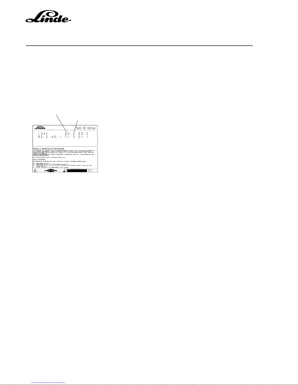
Service Training
Section 2
Page 72
H01 / Chapter 1
350 804 4701.0201
02.01
WINDOW 3 STORED FAULT MESSAGES
Window (3) displays all the fault messages stored in the EEPROM. The frequency of each fault is indicated
to the right of a colon behind the fault number. The fault counter can only count to 9 maximum.
These fault messages are stored permanently independent of turning the ignition on and off.
In this window the displayed errors can be cleared after pressing the "CE" key. Simultaneously a slash
"/" will appear behind the last error displayed in window 31.
Fault number
Fault frequency
The fault codes have the following meaning:
Fault messages:
The following reactions can occur on the truck with individual faults:
W Warning lamp flashing
K Truck driving at creep speed
B Truck brakes to a full stop or remains stationary when not moving
R Current achieves only start of pump control
E All power stages are without power
L engine goes to low idling speed
F Release magnet de-energised, truck braking with brake jets (restrictors)
S Safety relay in the controller de-energised, all power stages without power
Test conditions:
Battery min. 11.3 V
Potentiometer calibration --> window 8
NOTE: If no calibration is possible, there may be a problem with the pedal mechanism in addition to
a defective potentiometer.
VERSION 1.4 AND 1.5
Page 99

Section 2
Page 73
Service Training
H01 / Chapter 1
350 804 4701.0201
02.01
Error number
19 Not calibrated
A new LHC control module was installed in the vehicle so that the reference value of the
potentiometer must be transmitted to the module. --> window 8 (calibration)
NOTE: If the LHC module is not supplied with electric power for several hours, error code 19 can
appear --> window 8 ( calibration)
Truck responses: W – E – L – F – S
20 Invalid truck encoding
No truck type detected.
Possible cause could be a defective cable loom. Check by measuring the inputs and outputs on
the LHC module.
Truck responses: W – E – L – F – S
21 Invalid engine type encoding
The wrong engine type was identified (e. g. LPG instead of diesel engine)
Possible cause could be a faulty cable loom. Check by measuring the inputs and outputs on the
LHC module.
Truck responses: W – E – L – F - S
22 Invalid series encoding
A wrong series was identified (e. g. 351 instead of 350)
Possible cause could be a defective cable loom. Check by measuring the inputs and outputs on
the LHC module.
Truck responses: W – E – L – F – S
23 Invalid series / special version encoding
A wrong version was identified (e. g. instead of special version - fixed programmed speed
reduction, a series version)
Possible cause could be a defective cable loom. Check by measuring the inputs and outputs on
the LHC module.
Truck responses: W – E – L – F – S
26 Pressure sensor signal too high, and in particular over 9.5 V
The return voltage signal of pressure sensor 1B10 is over 9.5 V.
--> window 61
Possible causes: defective pressure sensor, shorted cable loom to and from sensor
Truck responses: W
27 Pressure switch and pressure sensor signals are both active
The switch and sensor signal at pressure sensor 1B10 are applied simultaneously.
Possible cause: defective pressure sensor
Truck responses: W
28 Pressure switch active although engine speed is zero
A switch signal 1B10 is applied although IC engine was not started and therefore no RPM are
indicated. --> window 6
Possible cause: pressure sensor defective, cable loom
Truck responses: W
VERSION 1.4 AND 1.5
Page 100

Service Training
Section 2
Page 74
H01 / Chapter 1
350 804 4701.0201
02.01
31 The voltage values of potentiometers 1B2.1 and 1B2.2 do not match, and neither is 0 V.
The values supplied by both potentiometers are not within the admissible tolerance range.
Possible cause: potentiometer
32 The voltage value of potentiometer 1B2.1 is either too low or too high.
The voltage value supplied by potentiometer 1B2.1 is not within the admissible range. It is either
below 0.8 V or over 9.2 V. Check this value in window 6. For a setting of the maximum values see
the description in window 6. If an adjustment can not be carried out successfully, the potentiometer
could be defective.
Truck responses: W – B – L
33 The voltage value of potentiometer 1B2.2 is either too low or too high.
The voltage value supplied by potentiometer 1B2.2 is not within the admissible range.
Possible cause: potentiometer
Truck responses: W – B – L
34 Both potentiometers 1B2.1 and 1B2.2 at 0 Volt
The voltage of approx. 10 Volt specified by the LHC box can not be processed further.
Possible causes: potentiometer not connected, potentiometer defective, cable loom
Truck responses: W – B – L
35 Travel direction signal encoding is not OK
The controller can not sense if it is a single-pedal or two-pedal vehicle.
Possible causes: encoding plug (near key switch); travel direction switch not connected or faulty,
cable loom (negative signals to LHC box not present, check)
--> Window 4)
Truck responses: W – B – L
36 Signal from travel direction switch
A signal expected from the travel direction switch can not be detected.
Possible causes: travel direction switch, cable loom (check negative signals coming from travel
direction switch to LHC box ) --> window 4
Truck responses: W – B – L
37 Brake switch 1 (1S5) breaker and maker have the same signal.
The brake switch does not change its outputs from 0 to 1 and from 1 to 0. --> window 4
Possible causes: brake switch defective, open connection (check negative signals coming from
brake switch to LHC module)
Truck responses: W – B
38 Switching sequence of brake switch 1 (1S5) and brake switch 2 (S14) is not OK.
The controller first expects (operation of brake pedal) brake switch 1 (1S5), before brake switch
2 (S14) becomes active. --> window 4
Possible causes: both brake switch connectors interchanged; brake switch 1 (1S5) not
connected, brake switch 1 defective; cable loom from brake switch 1 to LHC module
Truck responses: W – B
VERSION 1.4 AND 1.5
 Loading...