

Lincoln Electric VRTEX 360+, VRTEXTRANSPORT Operator's Manual
Operator’s Manual
®
VRTEX ®360+, VRTEX ®360, VRTEX
For use with machines having Code Numbers:
12782, 12592 And 12594
TRANSPORT
Register your machine:
www.lincolnelectric.com/register
Authorized Service and Distributor Locator:
www.lincolnelectric.com/locator
Save for future reference
Date Purchased
Code: (ex: 10859)
Serial: (ex: U1060512345)
IM10502 | Issue D ate 11/18
© Lincoln Global, Inc. All Rights Reserved.
+1.888.935.3878
THANK YOU FOR SELECTING
A QUALITY PRODUCT BY
LINCOLN ELEC TRIC.
PLEASE EXAMINE CARTON AND EQUIPMENT FOR
DAMAGE IMMEDIATELY
When this equipment is shipped, title passes to the purchaser
upon receipt by the carrier. Consequently, claims for material
damaged in shipment must be made by the purchaser against the
transportation company at the time the shipment is received.
SAFETY DEPENDS ON YOU
Lincoln arc welding and cutting equipment is designed and built
with safety in mind. However, your overall safety can be increased
by proper installation ... and thoughtful operation on your part.
DO NOT INSTALL, OPERATE OR REPAIR THIS EQUIPMENT
WITHOUT READING THIS MANUAL AND THE SAFETY
PRECAUTIONS CONTAINED THROUGHOUT. And, most importantly,
think before you act and be careful.
WARNING
This statement appears where the information must be followed
exactly to avoid serious personal injury or loss of life.
CAUTION
This statement appears where the information must be followed
to avoid minor personal injury or damage to this equipment.
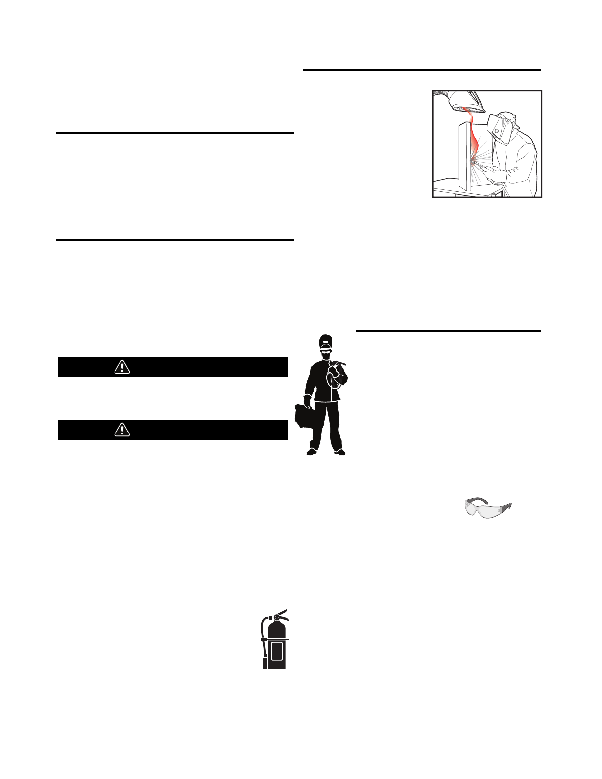
KEEP YOUR HEAD OUT OF THE FUMES.
DON’T get too close to the arc.
Use corrective lenses if necessary
to stay a reasonable distance
away from the arc.
READ and obey the Safety Data
Sheet (SDS) and the warning label
that appears on all containers of
welding materials.
USE ENOUGH VENTILATION or
exhaust at the arc, or both, to
keep the fumes and gases from
your breathing zone and the general area.
IN A LARGE ROOM OR OUTDOORS, natural ventilation may be
adequate if you keep your head out of the fumes (See below).
USE NATURAL DRAFTS or fans to keep the fumes away
from your face.
If you de velop unusual symptoms, see your supervisor.
Perhaps the welding atmosphere and ventilation system
should be checked.
WEAR CORRECT EYE, EAR &
BODY PROTECTION
PROTECT your eyes and face with welding helmet
properly fitted and with proper grade of filter plate
(See ANSI Z49.1).
PROTECT your body from welding spatter and arc
flash with protective clothing including woolen
clothing, flame-proof apron and gloves, leather
leggings, and high boots.
PROTECT others from splatter, flash, and glare
with protective screens or barriers.
IN SOME AREAS, protection from noise may be appropriate.
BE SURE protective equipment is in good condition.
Also, wear safety glasses in work area
AT ALL TIMES.
SPECIAL SITUATIONS
DO NOT WELD OR CUT containers or materials which previously
had been in contact with hazardous substances unless they are
properly cleaned. This is extremely dangerous.
DO NOT WELD OR CUT painted or plated parts unless special
precautions with ventilation have been taken. They can release
highly toxic fumes or gases.
Additional precautionary measures
PROTECT compressed gas cylinders from excessive heat,
mechanical shocks, and arcs; fasten cylinders so they cannot fall.
BE SURE cylinders are never grounded or part of an
electrical circuit.
REMOVE all potential fire hazards from welding area.
ALWAYS HAVE FIRE FIGHTING EQUIPMENT READY FOR
IMMEDIATE USE AND KNOW HOW TO USE IT.
Safety 01 of 04 - 5/16/2018
ii
SAFETY
SECTION A:
WARNINGS
CALIFORNIA PROPOSITION 65 WARNINGS
WARNING: Breathing diesel engine exhaust
exposes you to chemicals known to the State
of California to cause cancer and birth defects,
or other reproductive harm.
• Always start and operate the engine in a
well-ventilated area.
• If in an exposed area, vent the exhaust to the outside.
• Do not modify or tamper with the exhaust system.
• Do not idle the engine except as necessary.
For more information go to
www.P65 warnings.ca.gov/diesel
WARNING: This product, when used for welding or
cutting, produces fumes or gases which contain
chemicals known to the State of California to cause
birth defects and, in some cases, cancer. (California
Health & Safety Code § 25249.5 et seq.
)
with hot engine parts and igniting. Do not spill fuel when filling
tank. If fuel is spilled, wipe it up and do not start engine until
fumes have been eliminated.
1.d. Keep all equipment safety guards, covers
and devices in position and in good repair.
Keep hands, hair, clothing and tools away
from V-belts, gears, fans and all other
moving parts when starting, operating or
repairing equipment.
1.e. In some cases it may be necessary to remove safety guards to
perform required maintenance. Remove guards only when
necessary and replace them when the maintenance requiring
their removal is complete. Always use the greatest care when
working near moving parts.
1.f. Do not put your hands near the engine fan. Do not attempt to
override the governor or idler by pushing on the throttle control
rods while the engine is running.
1.g. To prevent accidentally starting gasoline engines while turning
the engine or welding generator during maintenance work,
disconnect the spark plug wires, distributor cap or magneto wire
as appropriate.
1.h. To avoid scalding, do not remove the radiator
pressure cap when the engine is
hot.
WARNING: Cancer and Reproductive Harm
www.P65warnings.ca.gov
ARC WELDING CAN BE HAZARDOUS. PROTECT
YOURSELF AND OTHERS FROM POSSIBLE SERIOUS
INJURY OR DEATH. KEEP CHILDREN AWAY.
PACEMAKER WEARERS SHOULD CONSULT WITH
THEIR DOCTOR BEFORE OPERATING.
Read and understand the following safety highlights. For
additional safety information, it is strongly recommended
that you purchase a copy of “Safety in Welding & Cutting ANSI Standard Z49.1” from the American Welding Society,
P.O. Box 351040, Miami, Florida 33135 or CSA Standard
W117.2-1974. A Free copy of “Arc Welding Safety” booklet
E205 is available from the Lincoln Electric Company,
22801 St. Clair Avenue, Cleveland, Ohio 44117-1199.
BE SURE THAT ALL INSTALLATION, OPERATION,
MAINTENANCE AND REPAIR PROCEDURES ARE
PERFORMED ONLY BY QUALIFIED INDIVIDUALS.
FOR ENGINE POWERED
EQUIPMENT.
1.a. Turn the engine off before troubleshooting
and maintenance work unless the
maintenance work requires it to be running.
1.b. Operate engines in open, well-ventilated areas or vent the engine
exhaust fumes outdoors.
1.c. Do not add the fuel near an open flame welding
arc or when the engine is running. Stop the
engine and allow it to cool before refueling to
prevent spilled fuel from vaporizing on contact
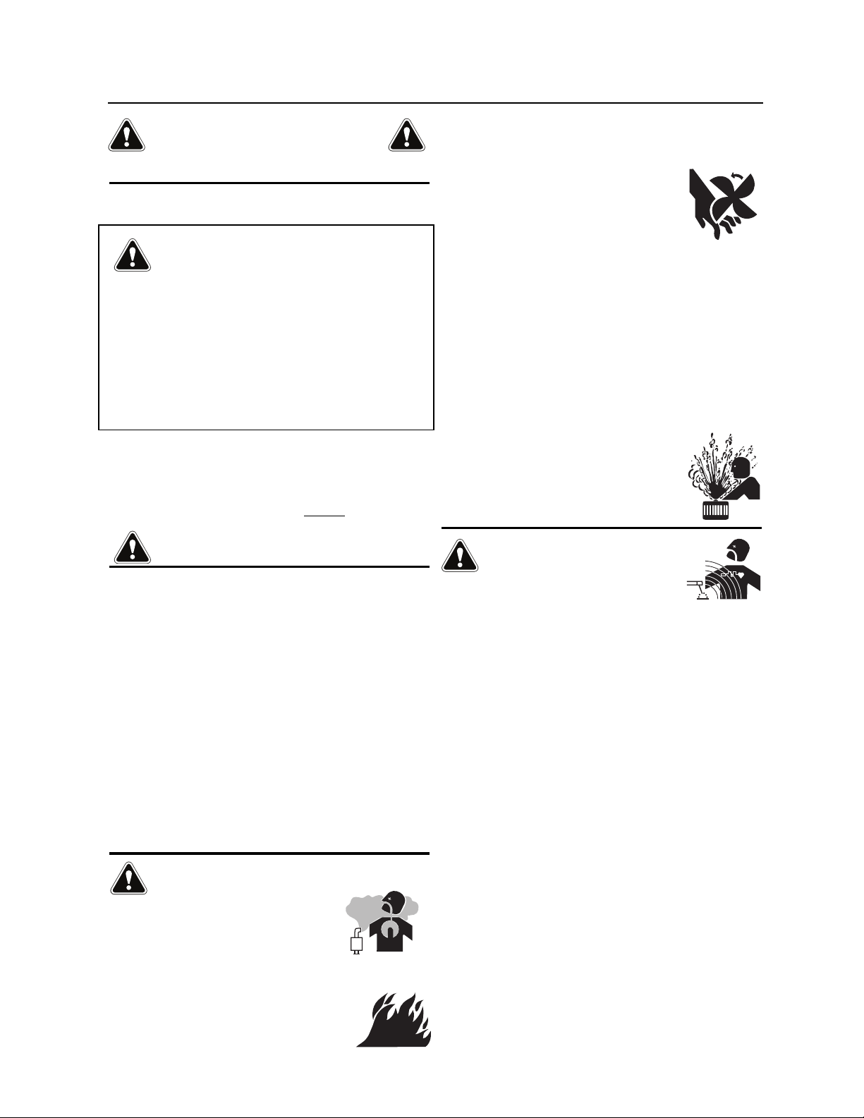
ELECTRIC AND
MAGNETIC FIELDS MAY
BE DANGEROUS
2.a. Electric current flowing through any conductor
causes localized Electric and Magnetic Fields (EMF).
Welding current creates EMF fields around welding cables
and welding machines
2.b. EMF fields may interfere with some pacemakers, and
welders having a pacemaker should consult their physician
before welding.
2.c. Exposure to EMF fields in welding may have other health effects
which are now not known.
2.d. All welders should use the following procedures in order to
minimize exposure to EMF fields from the welding circuit:
2.d.1. Route the electrode and work cables together - Secure
them with tape when possible.
2.d.2. Never coil the electrode lead around your body.
2.d.3. Do not place your body between the electrode and work
cables. If the electrode cable is on your right side, the
work cable should also be on your right side.
2.d.4. Connect the work cable to the workpiece as close as possible to the area being welded.
2.d.5. Do not work next to welding power source.
Safety 02 of 04 - 5/16/2018
iii
SAFETY
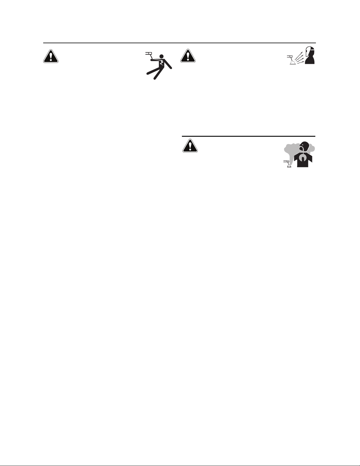
ELECTRIC SHOCK
CAN KILL.
3.a. The electrode and work (or ground) circuits are
electrically “hot” when the welder is on. Do
not touch these “hot” parts with your bare skin or wet clothing.
Wear dry, hole-free gloves to insulate hands.
3.b. Insulate yourself from work and ground using dry insulation.
Make certain the insulation is large enough to cover your full area
of physical contact with work and ground.
In addition to the normal safety precautions, if
welding must be performed under electrically
hazardous conditions (in damp locations or while
wearing wet clothing; on metal structures such as
floors, gratings or scaffolds; when in cramped
positions such as sitting, kneeling or lying, if there
is a high risk of unavoidable or accidental contact
with the workpiece or ground) use the following
equipment:
• Semiautomatic DC Constant Voltage (Wire) Welder.
• DC Manual (Stick) Welder.
• AC Welder with Reduced Voltage Control.
3.c. In semiautomatic or automatic wire welding, the electrode,
electrode reel, welding head, nozzle or semiautomatic welding
gun are also electrically “hot”.
3.d. Always be sure the work cable makes a good electrical
connection with the metal being welded. The connection should
be as close as possible to the area being welded.
3.e. Ground the work or metal to be welded to a good electrical (earth)
ground.
3.f. Maintain the electrode holder, work clamp, welding cable and
welding machine in good, safe operating condition. Replace
damaged insulation.
3.g. Never dip the electrode in water for cooling.
3.h. Never simultaneously touch electrically “hot” parts of electrode
holders connected to two welders because voltage
two can be the total of the open circuit voltage of both
welders.
3.i. When working above floor level, use a safety belt to protect
yourself from a fall should you get a shock.
3.j. Also see It ems 6.c. and 8.
between the
ARC RAYS CAN BURN.
4.a. Use a shield with the proper filter and cover plates to protect your
eyes from sparks and the rays of the arc when welding or
observing open arc welding. Headshield and filter lens should
conform to ANSI Z87. I standards.
4.b. Use suitable clothing made from durable flame-resistant material
to protect your skin and that of your helpers from the arc rays.
4.c. Protect other nearby personnel with suitable, non-flammable
screening and/or warn them not to watch the arc nor expose
themselves to the arc rays or to hot spatter or metal.
FUMES AND GASES
CAN BE DANGEROUS.
5.a. Welding may produce fumes and gases
hazardous to health. Avoid breathing these
fumes and gases. When welding, keep your head out of the fume.
Use enough ventilation and/or exhaust at the arc to keep fumes
and gases away from the breathing zone. When welding
hardfacing (see instructions on container or SDS)
or on lead or cadmium plated steel and other
metals or coatings which produce highly toxic
fumes, keep exposure as low as possible and
within applicable OSHA PEL and ACGIH TLV limits
using local exhaust or mechanical ventilation
unless exposure assessments indicate otherwise.
In confined spaces or in some circumstances,
outdoors, a respirator may also be required.
Additional precautions are also required when
welding
on galvanized steel.
5. b. The operation of welding fume control equipment is affected by
various factors including proper use and positioning of the
equipment, maintenance of the equipment and the specific
welding procedure and application involved. Worker exposure
level should be checked upon installation and periodically
thereafter to be certain it is within applicable OSHA PEL and
ACGIH TLV limits.
5.c. Do not weld in locations near chlorinated hydrocarbon vapors
coming from degreasing, cleaning or spraying operations. The
heat and rays of the arc can react with solvent vapors to form
phosgene, a highly toxic gas, and other irritating products.
5.d. Shielding gases used for arc welding can displace air and
injury or death. Always use enough ventilation, especially in
confined areas, to insure breathing air is safe.
5.e. Read and understand the manufacturer’s instructions for this
equipment and the consumables to be used, including the
Safety Data Sheet (SDS) and follow your employer’s safety
practices. SDS forms are available from your welding
distributor or from the manufacturer.
5.f. Also see item 1.b.
cause
Safety 03 of 04 - 5/16/2018
iv
SAFETY
WELDING AND CUTTING
SPARKS CAN CAUSE
FIRE OR EXPLOSION.
6.a. Remove fire hazards from the welding area. If
this is not possible, cover them to prevent the welding sparks
from starting a fire. Remember that welding sparks and hot
materials from welding can easily go through small cracks and
openings to adjacent areas. Avoid welding near hydraulic lines.
Have a fire extinguisher readily available.
6.b. Where compressed gases are to be used at the job site, special
precautions should be used to prevent hazardous situations.
Refer to “Safety in Welding and Cutting” (ANSI Standard Z49.1)
and the operating information for the equipment being used.
6.c. When not welding, make certain no part of the electrode circuit is
touching the work or ground. Accidental contact can cause
overheating and create a fire hazard.
6.d. Do not heat, cut or weld tanks, drums or containers until the
proper steps have been taken to insure that such procedures
will not cause flammable or toxic vapors from substances inside.
They can cause an explosion even though they have been
“cleaned”. For information, purchase “Recommended Safe
Practices for the Preparation for Welding and Cutting of
Containers and Piping That Have Held Hazardous Substances”,
AWS F4.1 from the American Welding Society
(see address above).
6.e. Vent hollow castings or containers before heating, cutting or
welding. They may explode.
6.f. Sparks and spatter are thrown from the welding arc. Wear oil free
protective garments such as leather gloves, heavy shirt, cuffless
trousers, high shoes and a cap over your hair. Wear ear plugs
when welding out of position or in confined places. Always wear
safety glasses with side shields when in a welding area.
6.g. Connect the work cable to the work as close to the welding area
as practical. Work cables connected to the building framework or
other locations away from the welding area increase the
possibility of the welding current passing through lifting chains,
crane cables or other alternate circuits. This can create fire
hazards or overheat lifting chains or cables until they fail.
6.h. Also see item 1.c.
6.I. Read and follow NFPA 51B “Standard for Fire Prevention During
Welding, Cutting and Other Hot Work”, available from NFPA, 1
Batterymarch Park, PO box 9101, Quincy, MA 022690-9101.
6.j. Do not use a welding power source for pipe thawing.
CYLINDER MAY EXPLODE IF
DAMAGED.
7.a. Use only compressed gas cylinders containing
the correct shielding gas for the process used
and properly operating regulators designed for
the gas and pressure used. All hoses, fittings,
etc. should be suitable for the application and
maintained in good condition.
7.b. Always keep cylinders in an upright position securely chained to
an undercarriage or fixed support.
7.c. Cylinders should be located:
• Away from areas where they may be struck or subjected
to physical damage.
• A safe distance from arc welding or cutting operations
and any other source of heat, sparks, or flame.
7.d. Never allow the electrode, electrode holder or any other
electrically “hot” parts to touch a cylinder.
7.e. Keep your head and face away from the cylinder valve outlet
when opening the cylinder valve.
7.f. Valve protection caps should always be in place and hand tight
except when the cylinder is in use or connected for use.
7.g. Read and follow the instructions on compressed gas cylinders,
associated equipment, and CGA publication P-l, “Precautions for
Safe Handling of Compressed Gases in Cylinders,” available from
the Compressed Gas Association, 14501 George Carter Way
Chantilly, VA 20151.
FOR ELECTRICALLY
POWERED EQUIPMENT.
8.a. Turn off input power using the disconnect
switch at the fuse box before working on
the equipment.
8.b. Install equipment in accordance with the U.S. National Electrical
Code, all local codes and the manufacturer’s recommendations.
8.c. Ground the equipment in accordance with the U.S. National
Electrical Code and the manufacturer’s recommendations.
Refer to
http://www.lincolnelectric.com/safety
for additional safety information.
Safety 04 of 04 - 5/16/2018
v

VRTEX® 360+, VRTEX® 360, VRTEX® TRANSPORT
Page
Installation .......................................................................................................................
Graphic Symbols That May Appear On This Machine Or In This Manual ............................................1
Technical Specifications ..................................................................................................................2
Safety Precautions ...........................................................................................................................3
Select Suitable Location ..................................................................................................................4
Environmental Area .........................................................................................................................4
Stacking ..........................................................................................................................................4
Tilting ..............................................................................................................................................4
Transport .........................................................................................................................................5
High Frequency Interference Protection ...........................................................................................5
Radio Frequency Interference ..........................................................................................................5
Product Description .........................................................................................................................6
User Interface Overview ...................................................................................................................7
Component Overview ......................................................................................................................8
Hardware Specifics........................................................................................................................11
Hardware Uncrating .......................................................................................................................14
Setup Procedure ............................................................................................................................15
Device Labels ................................................................................................................................18
Operation .........................................................................................................................
Powering On ..................................................................................................................................19
License Agreement ........................................................................................................................19
User Mode ............................................................................................................................... 20-29
User Mode .............................................................................................................................20
Login Screen ..........................................................................................................................20
Coupon Configuration Selection Screen ..................................................................................21
Process Selection Screen .......................................................................................................21
Table Setup Screens ..............................................................................................................21
Environment Screen ...............................................................................................................22
Gas Setup Screen ..................................................................................................................23
Virtual Welding Overview ........................................................................................................24
Visual Cues ............................................................................................................................24
GTAW Cues ............................................................................................................................25
LASER Screen ........................................................................................................................27
Technique Parameters ............................................................................................................27
Pass Number .........................................................................................................................28
Travel Direction ......................................................................................................................28
Bead Render ..........................................................................................................................29
Discontinuity Indicator ............................................................................................................29
Score .....................................................................................................................................29
Student Report .......................................................................................................................29
Instructor Mode ....................................................................................................................... 30-36
Instructor Mode And Admin Access ........................................................................................30
Weldometer ...........................................................................................................................31
Tolerance Editor .....................................................................................................................32
Scoring Modules ....................................................................................................................35
Update ...................................................................................................................................35
Options ..................................................................................................................................36
Additional Features ........................................................................................................................37
TABLE OF CONTENTS

VRTEX® 360+, VRTEX® 360, VRTEX® TRANSPORT
Page
Maintenance ....................................................................................................................
Cleaning & Maintenance ................................................................................................................42
Troubleshooting ..............................................................................................................
How To Use Troubleshooting Guide ................................................................................................43
Troubleshooting Guide ............................................................................................................. 44-45
Diagrams ..........................................................................................................................
Dimensions ...................................................................................................................................46
Wiring Diagrams ...................................................................................................................... 47-50
Parts ............................................................................................ parts.lincolnelectric.com
TABLE OF CONTENTS
INSTALLATIONVRTEX® 360+, VRTEX® 360, VRTEX® TRANSPORT
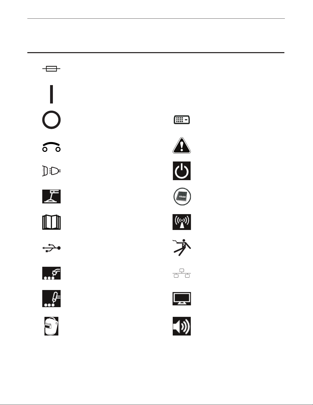
GRAPHIC SYMBOLS THAT MAY APPEAR ON THIS
MACHINE OR IN THIS MANUAL
FUSE
ON
OFF
CIRCUIT BREAKER
INPUT POWER
SMAW WELDING
U
I
1
1
INPUT VOLTAGE
INPUT CURRENT
DVI OUTPUT
WARNING OR CAUTION
Documentation must be consulted in all cases where this
symbol is displayed.
POWER BUTTON
VIRTUAL REALITY
WELDING
READ THIS OPERATORS
MANUAL COMPLETELY
USB
GMAW WELDING
GTAW WELDING
HELMET
COUPON ARM
CONNECTION
SHOCK HAZARD
ETHERNET
VGA OUTPUT
AUDIO OUTPUT
1
INSTALLATIONVRTEX® 360+, VRTEX® 360, VRTEX® TRANSPORT
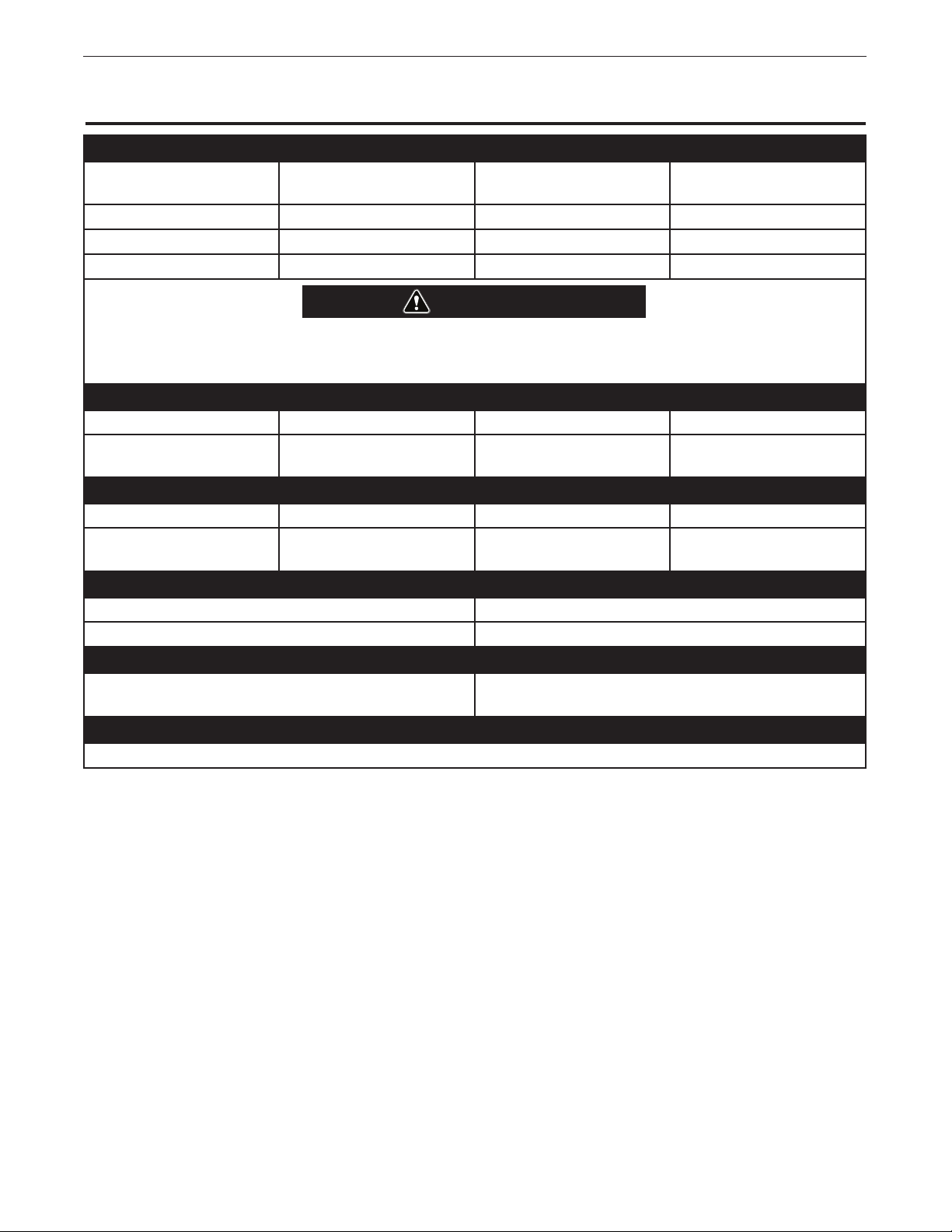
TECHNICAL SPECIFICATIONS
INPUT
MODEL DESCRIPTION INPUT VOLTAGE
± 10%
K3433-1 SINGLE USER 115/230 VAC (50/60 HZ) 2/1A SINGLE PHASE
K3434-1 DUAL USER 115/230 VAC (50/60 HZ) 4/2A SINGLE PHASE
K3435-1 TRANSPORT 115/230 VAC (50/60 HZ) 2/1A SINGLE PHASE
WARNING
THIS PRODUCT INCORPORATES A PROTECTIVE EARTH CIRCUIT IN THE AC POWER CORD. THE AC
PLUG SHOULD ONLY BE INSERTED INTO A SOCKET OUTLET PROVIDED WITH A PROTECTIVE EARTH
CONTACT. THE MAIN POWER DISCONNECT IS LOCATED IN THE REAR OF THE MACHINE.
PHYSICAL DIMENSIONS (MACHINE)
HEIGHT WIDTH DEPTH WEIGHT
38.5 in.
978 mm
HEIGHT WIDTH DEPTH WEIGHT
80.0 in.
2032 mm
OPERATING TEMPERATURE RANGE STORAGE TEMPERATURE RANGE
40° - 95° F (5° - 35° C) 32° - 149° F (0° - 65° C)
RELATIVE HUMIDITY* OPERATING ALTITUDE
80% For Temperatures Up To 88° F / 31° C
50% @ 104° F / 40° C
This product is for use in Pollution Degree 2 environment (Labratories, Test Stations, Office Environment).
20.0 in.
508 mm
34.5 in.
876 mm
PHYSICAL DIMENSIONS (STAND)
39.0 in.
991 mm
47.0 in.
1194 mm
TEMPERATURE RANGES
6562 Feet (2000 Meters)
ENVIRONMENT
INPUT CURRENT
(MAX.)
200 lbs.
90 kgs.
105 lbs.
48 kgs.
* Condensation on lenses may appear in high humidity environment. Run FMD (Face Mounted Display) for approximately 10 minutes to clear up
moisture from the lenses.
2
INSTALLATIONVRTEX® 360+, VRTEX® 360, VRTEX® TRANSPORT
Read entire installation section before starting
installation.
Do not place objects on the VR Table, Arm or on
Machine.
During lightning storms, turn off the system and
unplug it from the power outlet.
Before using the helmet please carefully read these
safety instructions.
Read this handbook and use the helmet device in
strict accordance in order to prevent any damage
to your eyes, other injury, loss of visual functions,
property damage or death.
We strongly advise you to get familiar with the helmet
device and its capabilities before you use it for the
first time.
SAFETY PRECAUTIONS
WARNING
ELECTRIC SHOCK can kill.
• Only qualified personnel should perform this
installation.
• Turn the input power OFF and unplug the machine from
the receptacle before working on this equipment.
• Always connect the VRTEX to a power supply grounded
according to the National Electrical Code and local codes.
• Do not use or store the helmet when wet or in wet areas.
• Do not wrap the cable around your neck, body or arms.
Immediately, stop using the Helmet and consult your physician if you
experience any of the following symptoms:
• Double vision or inability to focus on the display.
• Nausea or motion sickness.
• Eye fatigue or irritation.
• Headaches or dizziness.
• Aches and pain in the neck or shoulders.
HELMET SAFETY PRECAUTIONS
Adjust the headband so the helmet is secure and will not fall off in
use. Do not use the helmet if temperature is below 32°F/0°C or
above 104°F/40°C or in wet, humid, dusty or smoky areas.
Avoid dropping or impact of the helmet frame and displays. If
the helmet is damaged contact your retailer. There are no user
serviceable parts. Only qualified service personnel should perform any
repair on this product.
Avoid exposing the helmet to direct sunlight or intense / high-powered
lighting.
ESD SENSITIVITY
This headset eyepiece device may be sensitive to
electrostatic discharge of 8 kV or higher. Observe static
precautions such as discharging the body by touching
the metal chassis of the grounded equipment prior to
touching the eyepiece.
-------------------------------------------------------------------------
CAUTION
Misuse or overuse of this product may injure your eyes or
affect visual function.
Overexposure to video and flashing light may cause or aggravate the
following health effects to light-sensitive users:
• Eye disease and/or injury, Glaucoma.
• Epileptic (and other) Seizures.
• Heart disease or high blood pressure.
Consult your physician before using the helmet if you have been
diagnosed with or are susceptible to any of the above health effects.
Some users may experience a seizure when exposed to certain visual
images, including flashing lights or patterns. Even people who have
no history of seizures or epilepsy may have an undiagnosed condition
that can cause “photosensitive epileptic seizures.”
Seizures may cause loss of consciousness or convulsions that can
lead to injury from falling down or striking nearby objects.
Do not use the helmet when you are drowsy or fatigued.
3

SELECT SUITABLE
LOCATION
The machine will not operate in harsh environments. It is important
that simple preventative measures are followed in order to assure
long life and reliable operation. This product is for INDOOR USE
ONLY.
• Dirt and dust that can be drawn into the machine should be kept
to a minimum. Failure to observe these precautions can result in
excessive operating temperatures and nuisance shutdown.
• See Technical Specifications for operating environment
conditions.
• Do not place machine where monitor and/or helmet is exposed to
direct sunlight or high powered lighting.
• Do not place equipment near radiant heat sources.
• Do not place in a confined space. Allow a minimum of three feet
of clearance around machine and stand at all times. Adequate
ventilation is necessary.
• The fused power switch on the rear panel is the input power
disconnect device. Do not position the equipment so that it is
difficult to operate the fused power switch.
• Route and protect all cables to minimize exposure to damage.
• Single or Multi-Outlet surge protector (or Surge Suppressor) is
highly recommended to protect the machine from voltage spikes
going through the input line.
• An uninterruptible power supply (UPS) may be required for the
protection of the system from power irregularities and disruption.
NOTE: The system requires approximately 8’ L x 8’ D x
8’ H (2.4 m L x 2.4 m D x 2.4 m H) of space.
Keep the area free of obstruction for at least 3 feet in all directions
of both the stand and VR weld machine. In addition, be conscious of
where you are placing the unit to avoid magnetic fields, conductive
and high frequency objects and processes.
NOTE: Avoid setting up the VRTEX near high frequency
TIG machines and power sources.
Having these types of objects in the area can cause interference and
result in increased jitter and/or distortion in the motion tracking.
For best results, do not install VRTEX machine in the welding lab.
Electrical interference from power lines, though generally small, can
be present. Therefore all electrical power or lighting wiring within 50
feet of the welding area shall be enclosed in grounded rigid metallic
conduit. In the event the VRTEX is affected by interference, it is the
user’s responsibility to take steps to isolate and/or eliminate the interference.
An uninterruptible power supply (UPS) may be required for the
protection of the system from power irregularities or disruption.
It is strongly recommended that a single or Multi-Outlet surge
protector be used to protect the machine from any unwanted voltages
above a safe threshold.
INSTALLATIONVRTEX® 360+, VRTEX® 360, VRTEX® TRANSPORT
MULTIPLE SYSTEM INSTALLATIONS
If multiple systems are required to operate together in one location,
a unique frequency can be selected to reduce potential interference
between systems. In general, a setup (pole and table assembly) must
be kept at least 10 feet away from another setup using the same
frequency. By default the machines are programmed as followed:
SIDE B SIDE A
VRTEX 360+ SENSOR
SETTING 2
VRTEX 360 N/A SENSOR
VRTEX
TRANSPORT
If interference is noticed, the frequency can be adjusted by entering
Administrator Access, Options and choosing a different “Magnetic
Frequency ID” number.
N/A SENSOR
SENSOR
SETTING 3
SETTING 3
SETTING 3
ENVIRONMENTAL AREA
Keep the machine inside and dry at all times. Do not place it on wet
ground or in puddles. Never place liquids on top of the machine.
STACKING
The VRTEX cannot be stacked.
TILTING
Place the VRTEX directly on a secure, level surface.
4

TRANSPORT
The VRTEX has two swivel, locking casters for easy transport. When
the VRTEX is not being transported be sure the machine is on level
ground and lock the casters to prevent unwanted movement.
• Only transport the machine on level ground.
• Move the machine slowly and only when all four wheels are in
contact with the ground.
• Do not move over uneven ground or curbs.
• The VRTEX should never be lifted with an overhead crane.
HIGH FREQUENCY
INTERFERENCE
PROTECTION
CAUTION
INSTALLATIONVRTEX® 360+, VRTEX® 360, VRTEX® TRANSPORT
USE CAUTION WHEN OPERATING THIS MACHINE
AROUND OTHER EQUIPMENT.
• Large equipment, such as cranes, may interfere with the
operation of this machine.
• This machine may interfere with the operation of other
equipment in work / training area.
• High frequency process, such as TIG machines, may
interfere with the operation of this machine.
• Welding / cutting machine with improper grounding may
interfere with the operation of this machine.
------------------------------------------------------------------------
RADIO FREQUENCY
INTERFERENCE
This system contains a sensitive magnetic positioning sensor that
can become disturbed in the presence of conducted RF noise.
Disturbances can manifest themselves in slight jarring of the virtual
environment shown on the LCD display or via the headset eyepiece.
If interference on the sensor cable is an issue, it should be
repositioned until the jarring stops. In the case of noise on the AC
port being an issue, a noise suppressing ferrite bead can be added
to the AC power cord which will eliminate the interference. Please
contact your Lincoln Electric Support Center for details.
5
PRODUCT DESCRIPTION
The VRTEX is a virtual reality arc welding trainer. This computer
based training system is an educational tool designed to allow
students to practice their welding technique in a simulated
environment. It promotes the efficient transfer of welding skills from
the classroom to the welding booth, while reducing material waste
and energy consumption associated with traditional welding training.
The VRTEX is a virtual reality arc welding training machine only and
NOT a real arc welding machine. Please be aware of all standard
safety practices associated with welding. Some standard warnings
are included in this manual.
If the equipment is used in a manner not specified by the
manufacturer, the protection provided to the equipment and user may
be impaired.
Access panels are not to be removed except by qualified service
personnel due to risk of electric shock from accessible live parts.
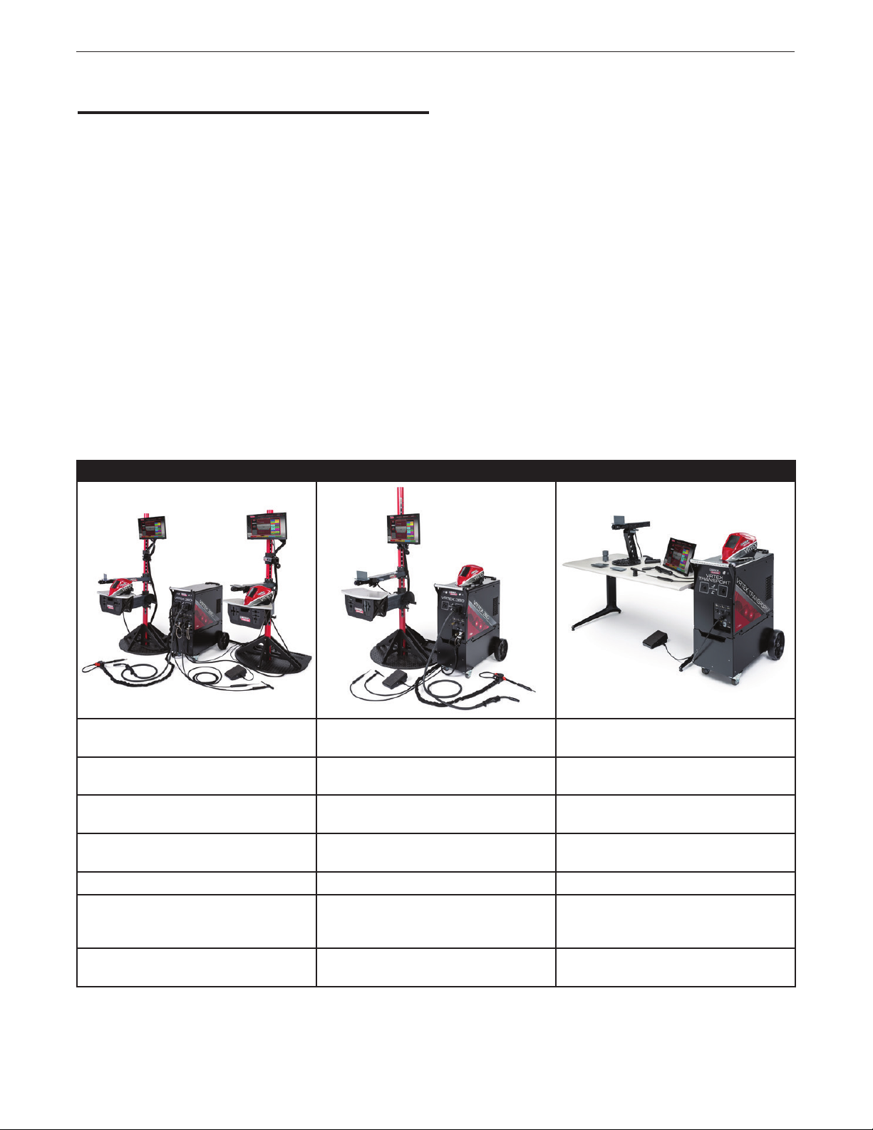
The VRTEX machine is available in three different configurations. This
manual can be used for all three.
Figure 1 – VRTEX configurations
INSTALLATIONVRTEX® 360+, VRTEX® 360, VRTEX® TRANSPORT
VRTEX 360+ VRTEX 360 VRTEX TRANSPORT
DUAL USER MACHINE: ALLOWS TRAINING OF
TWO PEOPLE AT THE SAME TIME.
QTY: 2, ACTIVE SMAW DEVICE, GMAW GUN,
GTAW GUN AND FILLER
QTY: 2, FULL SIZE STAND AND TABLE
ASSEMBLY
QTY: 2, FLAT PLATE, GROOVE, T, LAP JOINT,
2” PIPE, 6” PIPE, PIPE ON PLATE
6 DIFFERENT WELDING ENVIRONMENTS 6 DIFFERENT WELDING ENVIRONMENTS 4 DIFFERENT WELDING ENVIRONMENTS
THEORY, DEMO MODE, STUDENT REPLAY,
GRAPHIC CUES, BEND TEST, SCORING
MODULES
HORIZONTAL, VERTICAL, OVERHEAD
WELDING
ACTIVE SMAW DEVICE, GMAW GUN, GTAW
FULL SIZE STAND AND TABLE ASSEMBLY TABLE TOP ASSEMBLY
FLAT PLATE, GROOVE, T, LAP JOINT, 2” PIPE,
THEORY, DEMO MODE, STUDENT REPLAY,
SINGLE USER MACHINE SINGLE USER MACHINE
GTAW/SMAW/GMAW COMBO DEVICE AND
GUN AND FILLER
6” PIPE, PIPE ON PLATE
GRAPHIC CUES, BEND TEST, SCORING
MODULES
HORIZONTAL, VERTICAL, OVERHEAD
WELDING
FLAT PLATE, GROOVE, T, LAP JOINT
THEORY, DEMO MODE, STUDENT REPLAY,
GRAPHIC CUES
HORIZONTAL, VERTICAL WELDING
FILLER
6
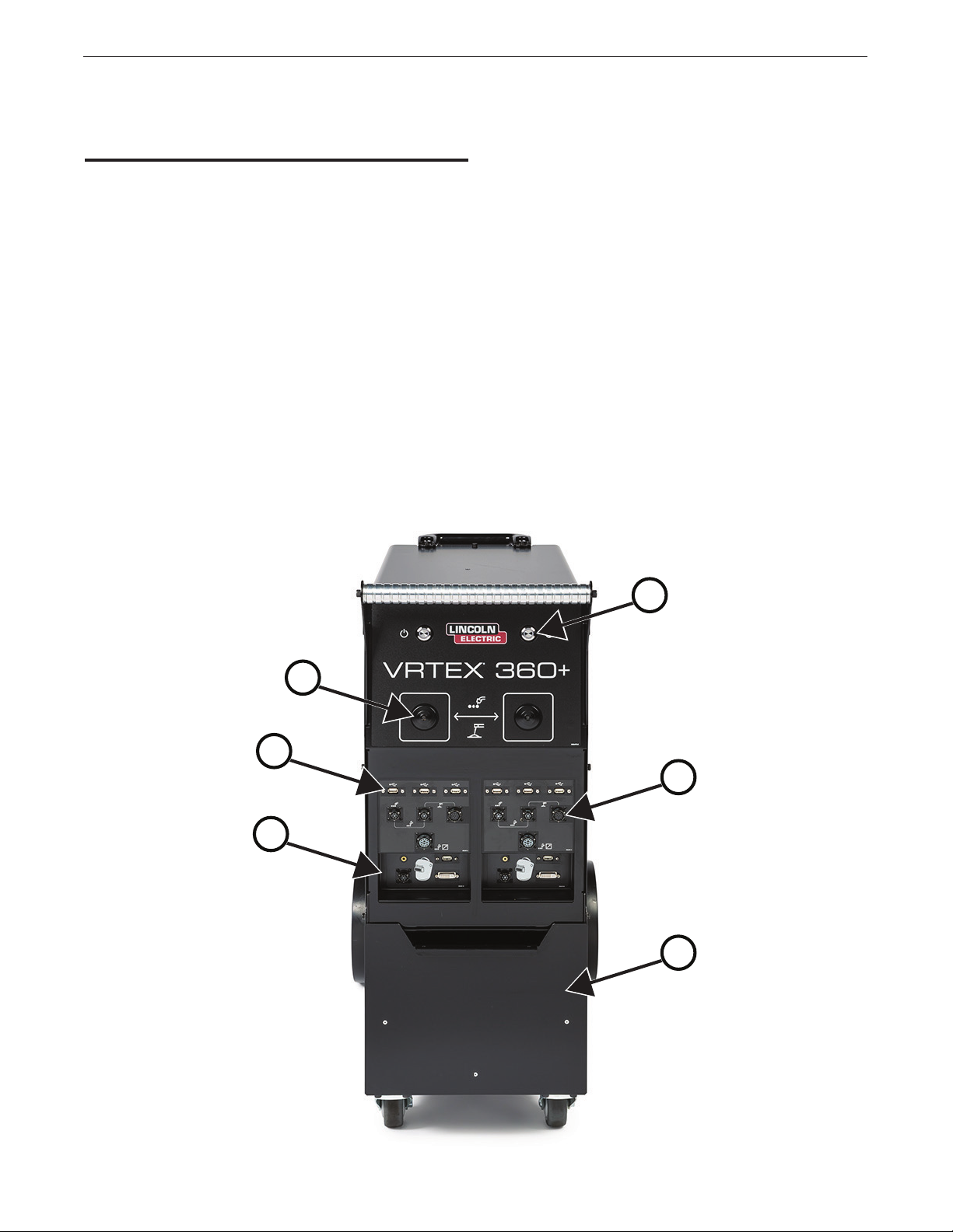
USER INTERFACE
OVERVIEW
See Figure 2 for locations of main unit control and connection points.
Dual user unit shown.
1. The Power Button powers on/off the VRTEX system.
2. The Cable Support Box Mount allows the cable support box to
attach the main unit to prevent unnecessary strain on gun device
cables.
3. The USB Ports are used to upload software and download user
data from the system.
4. The Gun Connections are used to attach the control cable for the
various VR welding devices.
5. The Helmet Connections are used to attach the control cables for
helmet.
6. The Front Storage Drawer is used to store one helmet and
coupons when the machine is not in use.
INSTALLATIONVRTEX® 360+, VRTEX® 360, VRTEX® TRANSPORT
Figure 2 – Front of machine
1
2
3
4
5
6
7
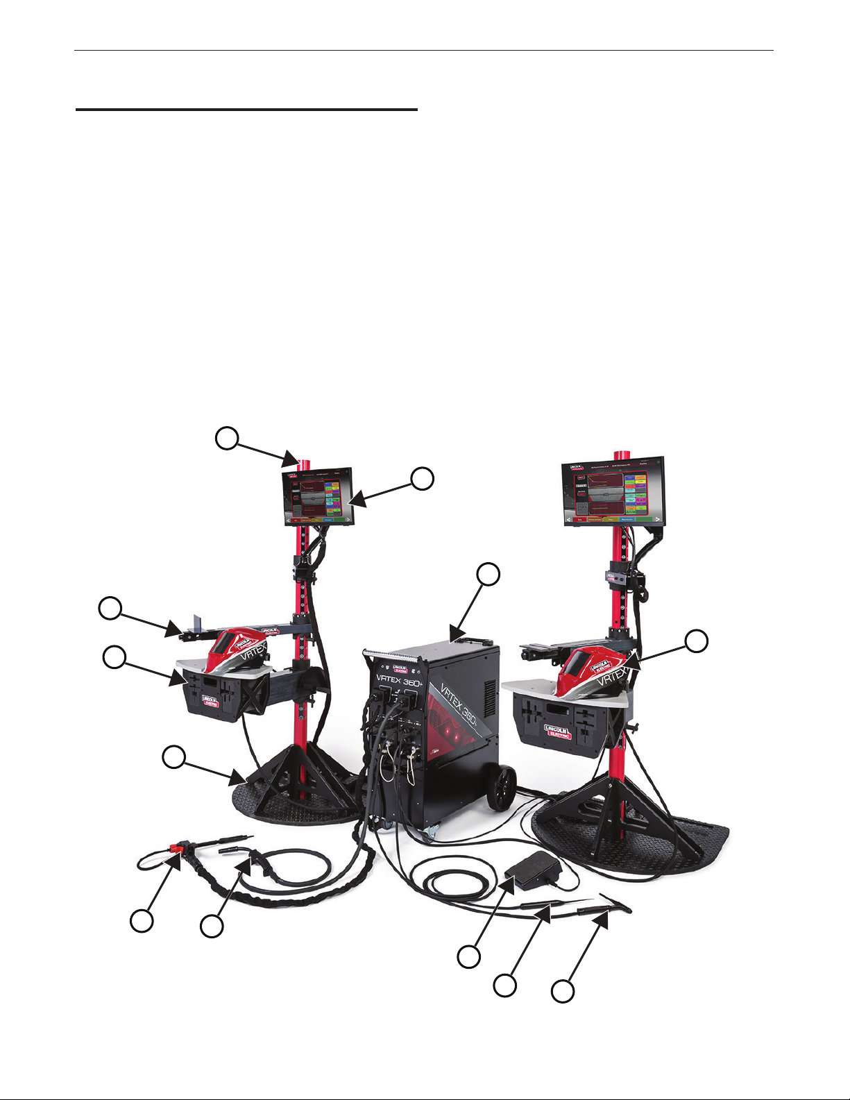
COMPONENT OVERVIEW
See Figure 3 for locations of VRTEX 360+ system components.
1. Post
2. Touchscreen Monitor
3. VRTEX Machine
4. Swingarm
5. Table
6. Stand Assembly
7. VR SMAW Device
8. VR GMAW/FCAW gun
9. Foot Amptrol
10. GTAW Filler
11. GTAW Torch
12. Helmet
Figure 3 – VRTEX 360+ system components
1
INSTALLATIONVRTEX® 360+, VRTEX® 360, VRTEX® TRANSPORT
2
3
4
12
5
6
7
8
9
10
8
11
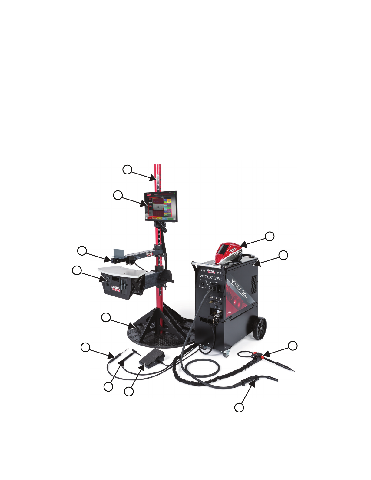
See Figure 4 for locations of VRTEX 360 system components.
1. Post
2. Touchscreen Monitor
3. Helmet
4. Swingarm
5. VRTEX Machine
6. Table
7. Stand Assembly
8. GTAW Filler
9. GTAW Torch
10. Foot Amptrol
11. VR GMAW/FCAW gun
12. VR SMAW Device
Figure 4 – VRTEX 360 system components
1
INSTALLATIONVRTEX® 360+, VRTEX® 360, VRTEX® TRANSPORT
2
3
4
6
7
8
5
12
9
10
11
9
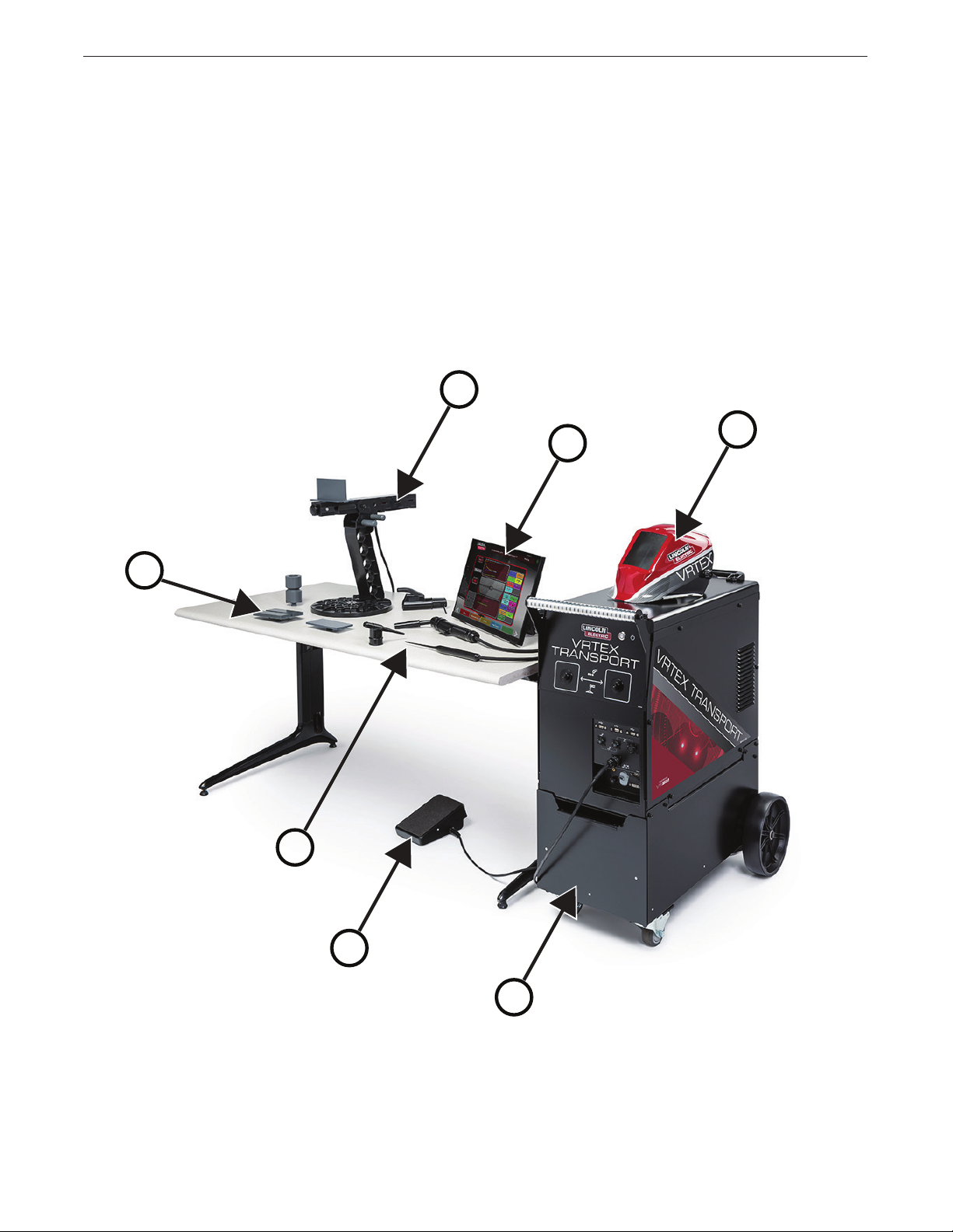
See Figure 5 for locations of VRTEX Transport system components.
1. Coupon Stand
2. Touchscreen Monitor
3. Helmet
4. Coupons
5. GTAW Filler
VR GTAW/SMAW/GMAW Combo Device
6. Foot Amptrol
7. VRTEX Machine
Figure 5 – VRTEX transport system components
1
INSTALLATIONVRTEX® 360+, VRTEX® 360, VRTEX® TRANSPORT
2
3
4
5
6
7
10

HARDWARE SPECIFICS
VR GMAW/FCAW GUN
The VR gun has a trigger that is used during the simulation of GMAW
and FCAW processes to initiate and maintain the simulated welding
arc.
Figure 6 – VR GMAW/FCAW gun
VR SMAW DEVICE
INSTALLATIONVRTEX® 360+, VRTEX® 360, VRTEX® TRANSPORT
Figure 7 – VR SMAW device
VR GTAW TORCH AND FILLER
The VR GTAW torch also includes a footpedal that is used during the
simulation of GTAW processes to initiate and maintain the simulated
welding arc. The VR GTAW torch and filler should be placed in the
front storage drawer when not in use. Also note the LASER screen
will evaluate both the GTAW torch and filler. The welding arc can be
initiated by the footpedal, hand amptrol or lift start.
Figure 8 – VR GTAW torch and filler
The VR SMAW device has a rod that represents a stick electrode.
This rod retracts when a virtual arc is struck to simulate the electrode
burning off during the virtual welding process. When the virtual
electrode burns down to a stub, the rod will stop retracting and the
user will no longer be able to weld. When the user presses “new
stick” in the orange actions and cues menu icon, the rod extends out,
simulating that a new electrode was put into the VR SMAW device.
In order to strike an arc with the VR SMAW device, gently strike or
tap the tip of the rod (of the VR SMAW device) on the coupon being
welded. To break the arc, move the VR SMAW device rod away from
the work piece.
CAUTION
Do not try to strike the arc with excessive force, as
the arc start is distance based. Excessive force may
result in damage to the VR SMAW device.
The angle of the rod can be changed by squeezing the handle of the
VR SMAW device. This allows the rod to be moved into the 45 or
90 degree position. Once the rod is at one of these angles, release
the handle. The rod should now be fixed in that position. Do not
change the rod angle while the rod is extending or
retracting.
11
 Loading...