

Lincoln Electric VANTAGE 600 SD Operator's Manual
Operator’s Manual
VANTAGE® 600 SD
For use with machines having Code Numbers:
11981
Register your machine:
www.lincolnelectric.com/register
Authorized Service and Distributor Locator:
www.lincolnelectric.com/locator
Save for future reference
Date Purchased
Code: (ex: 10859)
Serial: (ex: U1060512345)
IM10177 | Issue D ate Jun-16
© Lincoln Global, Inc. All Rights Reserved.
Need Help? Call 1.888.935.3877
to talk to a Service Representative
Hours of Operation:
8:00 AM to 6:00 PM (ET) Mon. thru Fri.
After hours?
Use “Ask the Experts” at lincolnelectric.com
A Lincoln Service Representative will contact you
no later than the following business day.
For Service outside the USA:
Email: globalservice@lincolnelectric.com
THANK YOU FOR SELECTING
A QUALITY PRODUCT BY
LINCOLN ELEC TRIC.
PLEASE EXAMINE CARTON AND EQUIPMENT FOR
DAMAGE IMMEDIATELY
When this equipment is shipped, title passes to the purchaser
upon receipt by the carrier. Consequently, claims for material
damaged in shipment must be made by the purchaser against the
transportation company at the time the shipment is received.
SAFETY DEPENDS ON YOU
Lincoln arc welding and cutting equipment is designed and built
with safety in mind. However, your overall safety can be increased
by proper installation ... and thoughtful operation on your part.
DO NOT INSTALL, OPERATE OR REPAIR THIS EQUIPMENT
WITHOUT READING THIS MANUAL AND THE SAFETY
PRECAUTIONS CONTAINED THROUGHOUT. And, most importantly,
think before you act and be careful.
WARNING
This statement appears where the information must be followed
exactly to avoid serious personal injury or loss of life.
CAUTION
This statement appears where the information must be followed
to avoid minor personal injury or damage to this equipment.
KEEP YOUR HEAD OUT OF THE FUMES.
DON’T get too close to the arc.
se corrective lenses if necessary
U
to stay a reasonable distance
away from the arc.
READ and obey the Safety Data
Sheet (SDS) and the warning label
that appears on all containers of
welding materials.
USE ENOUGH VENTILATION or
exhaust at the arc, or both, to
keep the fumes and gases from
your breathing zone and the general area.
IN A LARGE ROOM OR OUTDOORS, natural ventilation may be
adequate if you keep your head out of the fumes (See below).
USE NATURAL DRAFTS or fans to keep the fumes away
from your face.
If you de velop unusual symptoms, see your supervisor.
Perhaps the welding atmosphere and ventilation system
should be checked.
WEAR CORRECT EYE, EAR &
BODY PROTECTION
PROTECT your eyes and face with welding helmet
properly fitted and with proper grade of filter plate
(See ANSI Z49.1).
PROTECT your body from welding spatter and arc
flash with protective clothing including woolen
clothing, flame-proof apron and gloves, leather
leggings, and high boots.
PROTECT others from splatter, flash, and glare
with protective screens or barriers.
IN SOME AREAS, protection from noise may be appropriate.
BE SURE protective equipment is in good condition.
Also, wear safety glasses in work area
AT ALL TIMES.
SPECIAL SITUATIONS
DO NOT WELD OR CUT containers or materials which previously
had been in contact with hazardous substances unless they are
properly cleaned. This is extremely dangerous.
DO NOT WELD OR CUT painted or plated parts unless special
precautions with ventilation have been taken. They can release
highly toxic fumes or gases.
Additional precautionary measures
PROTECT compressed gas cylinders from excessive heat,
mechanical shocks, and arcs; fasten cylinders so they cannot fall.
BE SURE cylinders are never grounded or part of an
electrical circuit.
REMOVE all potential fire hazards from welding area.
ALWAYS HAVE FIRE FIGHTING EQUIPMENT READY FOR
IMMEDIATE USE AND KNOW HOW TO USE IT.
Safety 01 of 04 - 06/15/2016
SECTION A:
WARNINGS
CALIFORNIA PROPOSITION 65 WARNINGS
Diesel Engines
Diesel engine exhaust and some of its constituents are known
to the State of California to cause cancer, birth defects, and other
reproductive harm.
Gasoline Engines
The engine exhaust from this product contains chemicals known
to the State of California to cause cancer, birth defects, or other
reproductive harm.
ARC WELDING CAN BE HAZARDOUS. PROTECT
YOURSELF AND OTHERS FROM POSSIBLE SERIOUS
INJURY OR DEATH. KEEP CHILDREN AWAY.
PACEMAKER WEARERS SHOULD CONSULT WITH
THEIR DOCTOR BEFORE OPERATING.
Read and understand the following safety highlights. For
additional safety information, it is strongly recommended
that you purchase a copy of “Safety in Welding & Cutting ANSI Standard Z49.1” from the American Welding Society,
P.O. Box 351040, Miami, Florida 33135 or CSA Standard
W117.2-1974. A Free copy of “Arc Welding Safety” booklet
E205 is available from the Lincoln Electric Company,
22801 St. Clair Avenue, Cleveland, Ohio 44117-1199.
BE SURE THAT ALL INSTALLATION, OPERATION,
MAINTENANCE AND REPAIR PROCEDURES ARE
PERFORMED ONLY BY QUALIFIED INDIVIDUALS.
SAFETY
1.d. Keep all equipment safety guards, covers
and devices in position and in good repair.
Keep hands, hair, clothing and tools away
from V-belts, gears, fans and all other
moving parts when starting, operating or
repairing equipment.
1.e. In some cases it may be necessary to remove safety guards to
perform required maintenance. Remove guards only when
necessary and replace them when the maintenance requiring
heir removal is complete. Always use the greatest care when
t
working near moving parts.
1.f. Do not put your hands near the engine fan. Do not attempt to
override the governor or idler by pushing on the throttle control
rods while the engine is running.
1.g. To prevent accidentally starting gasoline engines while turning
the engine or welding generator during maintenance work,
disconnect the spark plug wires, distributor cap or magneto wire
as appropriate.
1.h. To avoid scalding, do not remove the radiator
pressure cap when the engine is
hot.
ELECTRIC AND
MAGNETIC FIELDS MAY
BE DANGEROUS
2.a. Electric current flowing through any conductor
causes localized Electric and Magnetic Fields (EMF).
Welding current creates EMF fields around welding cables
and welding machines
FOR ENGINE POWERED
EQUIPMENT.
1.a. Turn the engine off before troubleshooting
and maintenance work unless the
maintenance work requires it to be running.
1.b. Operate engines in open, well-ventilated
areas or vent the engine exhaust fumes outdoors.
1.c. Do not add the fuel near an open flame
welding arc or when the engine is running.
Stop the engine and allow it to cool before
refueling to prevent spilled fuel from
vaporizing on contact with hot engine parts
and igniting. Do not spill fuel when filling
tank. If fuel is spilled, wipe it up and do not start engine until
fumes have been eliminated.
2.b. EMF fields may interfere with some pacemakers, and
welders having a pacemaker should consult their physician
before welding.
2.c. Exposure to EMF fields in welding may have other health effects
which are now not known.
2.d. All welders should use the following procedures in order to
minimize exposure to EMF fields from the welding circuit:
2.d.1. Route the electrode and work cables together - Secure
them with tape when possible.
2.d.2. Never coil the electrode lead around your body.
2.d.3. Do not place your body between the electrode and work
cables. If the electrode cable is on your right side, the
work cable should also be on your right side.
2.d.4. Connect the work cable to the workpiece as close as possible to the area being welded.
2.d.5. Do not work next to welding power source.
Safety 02 of 04 - 06/15/2016
SAFETY
ELECTRIC SHOCK
CAN KILL.
3.a. The electrode and work (or ground) circuits are
electrically “hot” when the welder is on. Do
not touch these “hot” parts with your bare skin or wet clothing.
Wear dry, hole-free gloves to insulate hands.
3.b. Insulate yourself from work and ground using dry insulation.
Make certain the insulation is large enough to cover your full area
f physical contact with work and ground.
o
In addition to the normal safety precautions, if
welding must be performed under electrically
hazardous conditions (in damp locations or while
wearing wet clothing; on metal structures such as
floors, gratings or scaffolds; when in cramped
positions such as sitting, kneeling or lying, if there
is a high risk of unavoidable or accidental contact
with the workpiece or ground) use the following
equipment:
• Semiautomatic DC Constant Voltage (Wire) Welder.
• DC Manual (Stick) Welder.
• AC Welder with Reduced Voltage Control.
3.c. In semiautomatic or automatic wire welding, the electrode,
electrode reel, welding head, nozzle or semiautomatic welding
gun are also electrically “hot”.
3.d. Always be sure the work cable makes a good electrical
connection with the metal being welded. The connection should
be as close as possible to the area being welded.
3.e. Ground the work or metal to be welded to a good electrical (earth)
ground.
3.f. Maintain the electrode holder, work clamp, welding cable and
welding machine in good, safe operating condition. Replace
damaged insulation.
3.g. Never dip the electrode in water for cooling.
3.h. Never simultaneously touch electrically “hot” parts of electrode
holders connected to two welders because voltage
two can be the total of the open circuit voltage of both
welders.
3.i. When working above floor level, use a safety belt to protect
yourself from a fall should you get a shock.
between the
ARC RAYS CAN BURN.
4.a. Use a shield with the proper filter and cover plates to protect your
eyes from sparks and the rays of the arc when welding or
observing open arc welding. Headshield and filter lens should
conform to ANSI Z87. I standards.
4.b. Use suitable clothing made from durable flame-resistant material
to protect your skin and that of your helpers from the arc rays.
4.c. Protect other nearby personnel with suitable, non-flammable
screening and/or warn them not to watch the arc nor expose
themselves to the arc rays or to hot spatter or metal.
FUMES AND GASES
CAN BE DANGEROUS.
5.a. Welding may produce fumes and gases
hazardous to health. Avoid breathing these fumes and gases.
When welding, keep your head out of the fume. Use enough
ventilation and/or exhaust at the arc to keep fumes and gases
away from the breathing zone. When welding hardfacing
(see instructions on container or SDS) or on lead
or cadmium plated steel and other metals or
coatings which produce highly toxic fumes, keep
exposure as low as possible and within applicable
OSHA PEL and ACGIH TLV limits using local
exhaust or mechanical ventilation unless exposure
assessments indicate otherwise. In confined
spaces or in some circumstances, outdoors, a
respirator may also be required. Additional
precautions are also required when welding
on galvanized steel.
5. b. The operation of welding fume control equipment is affected by
various factors including proper use and positioning of the
equipment, maintenance of the equipment and the specific
welding procedure and application involved. Worker exposure
level should be checked upon installation and periodically
thereafter to be certain it is within applicable OSHA PEL and
ACGIH TLV limits.
5.c. Do not weld in locations near chlorinated hydrocarbon vapors
coming from degreasing, cleaning or spraying operations. The
heat and rays of the arc can react with solvent vapors to form
phosgene, a highly toxic gas, and other irritating products.
3.j. Also see It ems 6.c. and 8.
5.d. Shielding gases used for arc welding can displace air and
cause
injury or death. Always use enough ventilation, especially in
confined areas, to insure breathing air is safe.
5.e. Read and understand the manufacturer’s instructions for this
equipment and the consumables to be used, including the
Safety Data Sheet (SDS) and follow your employer’s safety
practices. SDS forms are available from your welding
distributor or from the manufacturer.
5.f. Also see item 1.b.
Safety 03 of 04 - 06/15/2016
SAFETY
WELDING AND CUTTING
SPARKS CAN CAUSE
FIRE OR EXPLOSION.
6.a. Remove fire hazards from the welding area. If
this is not possible, cover them to prevent the welding sparks
rom starting a fire. Remember that welding sparks and hot
f
materials from welding can easily go through small cracks and
openings to adjacent areas. Avoid welding near hydraulic lines.
Have a fire extinguisher readily available.
6.b. Where compressed gases are to be used at the job site, special
precautions should be used to prevent hazardous situations.
Refer to “Safety in Welding and Cutting” (ANSI Standard Z49.1)
and the operating information for the equipment being used.
6.c. When not welding, make certain no part of the electrode circuit is
touching the work or ground. Accidental contact can cause
overheating and create a fire hazard.
6.d. Do not heat, cut or weld tanks, drums or containers until the
proper steps have been taken to insure that such procedures
will not cause flammable or toxic vapors from substances inside.
They can cause an explosion even though they have been
“cleaned”. For information, purchase “Recommended Safe
Practices for the Preparation for Welding and Cutting of
Containers and Piping That Have Held Hazardous Substances”,
AWS F4.1 from the American Welding Society
(see address above).
6.e. Vent hollow castings or containers before heating, cutting or
welding. They may explode.
6.f. Sparks and spatter are thrown from the welding arc. Wear oil free
protective garments such as leather gloves, heavy shirt, cuffless
trousers, high shoes and a cap over your hair. Wear ear plugs
when welding out of position or in confined places. Always wear
safety glasses with side shields when in a welding area.
6.g. Connect the work cable to the work as close to the welding area
as practical. Work cables connected to the building framework or
other locations away from the welding area increase the
possibility of the welding current passing through lifting chains,
crane cables or other alternate circuits. This can create fire
hazards or overheat lifting chains or cables until they fail.
6.h. Also see item 1.c.
CYLINDER MAY EXPLODE IF
DAMAGED.
7.a. Use only compressed gas cylinders containing
the correct shielding gas for the process used
and properly operating regulators designed for
the gas and pressure used. All hoses, fittings,
tc. should be suitable for the application and
e
maintained in good condition.
7.b. Always keep cylinders in an upright position securely chained to
an undercarriage or fixed support.
7.c. Cylinders should be located:
• Away from areas where they may be struck or subjected
to physical damage.
• A safe distance from arc welding or cutting operations
and any other source of heat, sparks, or flame.
7.d. Never allow the electrode, electrode holder or any other
electrically “hot” parts to touch a cylinder.
7.e. Keep your head and face away from the cylinder valve outlet
when opening the cylinder valve.
7.f. Valve protection caps should always be in place and hand tight
except when the cylinder is in use or connected for use.
7.g. Read and follow the instructions on compressed gas cylinders,
associated equipment, and CGA publication P-l, “Precautions for
Safe Handling of Compressed Gases in Cylinders,” available from
the Compressed Gas Association, 14501 George Carter Way
Chantilly, VA 20151.
FOR ELECTRICALLY
POWERED EQUIPMENT.
8.a. Turn off input power using the disconnect
switch at the fuse box before working on
the equipment.
8.b. Install equipment in accordance with the U.S. National Electrical
Code, all local codes and the manufacturer’s recommendations.
6.I. Read and follow NFPA 51B “Standard for Fire Prevention During
Welding, Cutting and Other Hot Work”, available from NFPA, 1
Batterymarch Park, PO box 9101, Quincy, MA 022690-9101.
6.j. Do not use a welding power source for pipe thawing.
8.c. Ground the equipment in accordance with the U.S. National
Electrical Code and the manufacturer’s recommendations.
Refer to
http://www.lincolnelectric.com/safety
for additional safety information.
Safety 04 of 04 - 06/15/2016

I
ns
Oper
P
ta
l
l
a
ti
o
n
.
.
.
.
.
.
.
.
.
.
.
P
ro
d
u
c
t
D
T
e
c
h
n
ic
a
l
Sa
f
e
t
y
P
re
V
RD
(
V
o
lt
a
L
o
c
a
t
io
n
a
P
re
-
O
p
e
ra
Re
mo
te
Co
We
lding Te
We
lding Output Ca
P
ulse
We
lding
Ca
ble
Insta
M
a
c
hine
G
Auxilia
ry P
Sta
ndby P
Co
nne
c
tio
Co
nne
c
tion of L
Conne
c
tio
Co
nne
c
tion o
Ca
ble
Induc
Co
ntro
l Ca
a
tio
n
.
.
.
.
.
.
.
.
.
.
.
Safety Instructions
Re
c
o
mme
Co
ntr
o
ls
a
We
lde
r
O
pe
Typical Fuel Consumption
Common Welding Practices
Definition of Welding Modes
.
.
.
.
.
.
.
.
.
.
.
.
.
.
.
.
.
.
.
.
.
.
.
.
.
.
.
.
.
.
.
.
.
.
.
.
.
.
.
.
e
sc
rip
t
io
n
.
.
.
.
.
.
.
.
.
.
.
Sp
e
c
if
ic
a
t
io
n
s
.
.
.
.
.
.
.
.
c
a
u
t
io
n
s
.
.
.
.
.
.
.
.
.
.
.
.
g
e
Re
d
u
c
t
io
n
D
e
vic
e
)
.
.
n
d
V
e
n
t
ila
t
io
n
.
.
.
.
.
.
.
.
St
o
rin
g
.
.
.
.
.
.
.
.
.
.
.
.
St
a
c
k
in
g
.
.
.
.
.
.
.
.
.
.
.
An
g
le
o
f
O
p
e
ra
t
io
n
.
.
.
L
if
t
in
g
.
.
.
.
.
.
.
.
.
.
.
.
.
H
ig
h
Alt
it
u
d
e
O
p
e
ra
t
io
n
H
ig
h
T
e
mp
e
ra
t
u
re
O
p
e
ra
Co
ld
We
a
t
h
e
r
St
a
rt
in
g
.
T
o
w
in
g
.
.
.
.
.
.
.
.
.
.
.
.
V
e
h
ic
le
M
o
u
n
t
in
g
.
.
.
.
t
io
n
E
n
g
in
e
Se
rvic
e
.
.
.
.
O
il
.
.
.
.
.
.
.
.
.
.
.
.
.
.
.
.
F
u
e
l
.
.
.
.
.
.
.
.
.
.
.
.
.
.
F
u
e
l
Ca
p
.
.
.
.
.
.
.
.
.
.
.
Engine
Co
o
ling Syste
Ba
tte
ry Co
nne
Exha
ust Outle
Spa
rk
Arre
sto
Air Cle
a
ne
r Insta
ntro
l
.
. .
. .
. .
rmina
ls
.
. .
. .
ble
s
. .
. .
. .
. .
. .
lla
tio
n
. .
. .
. .
ro
unding
. .
. .
o
w
e
r Re
c
e
pta
o
w
e
r Co
nne
c
tio
n o
f VANTAG
n o
f Wire
f Ac
ta
nc
Ele
ble
Co
G
e
Insta
.
.
.
.
.
.
nde
Welde
Ge
nd
S
Engine
We
r
a
tio
D
uty
S
tic
CC-S
D
o
Touch Start TIG Mode
Making A Weld
Non-Synergic Welding Modes
ne
.
d
ne
w
c
.
.
e
lde
k
inc
ro
e
a
tro
de
nne
ra
lla
.
.
.
.
A
pplic
r
r
a
ttings
r
n
Cyc
We
tic
nhill
E
o
ln Elec
Fe
e
ders w
ss the
nd its Effe
Vo
c
tio
l G
uide
tion Instruc
.
.
.
.
.
.
.
.
.
.
.
atio
.
.
.
to
r
.
.
Co
ntr
Co
ntr
.
.
.
.
le
.
lding
k
M
o
Pipe
lta
.
.
.
.
.
c
®
ns
.
o
o
.
.
de
c
tio
t P
r
. .
. .
. .
. .
. .
. .
le
ns
6
tric
Arc
ge
line
.
.
.
.
.
ns
.
.
.
.
.
.
ls
ls
.
.
M
M
.
s
.
.
.
.
.
.
.
.
o
.
o
.
ipe
ll
0
.
n
. .
.
. .
. .
. .
. .
. .
. .
. .
. .
0
SD to
Wire
ith Co
Wire
c
ts o
Se
.
.
s
tio
.
.
.
.
.
.
.
.
.
.
.
.
.
.
.
.
.
.
.
.
.
.
de
.
.
de
.
.
.
.
.
.
.
m
. .
. .
. .
. .
. .
. .
. .
. .
. .
. .
. .
. .
nsing
.
.
.
.
ns
.
.
.
.
.
.
.
.
.
.
.
.
.
.
.
.
.
.
.
.
.
.
.
.
.
.
.
.
.
.
.
.
.
.
.
. .
. .
. .
. .
. .
. .
. .
. .
. .
. .
. .
. .
F
F
n We
.
.
.
.
.
.
.
.
.
.
.
.
.
.
.
.
.
.
.
.
.
.
.
.
.
.
.
.
.
.
.
.
.
.
.
.
.
.
.
.
.
.
.
.
.
.
.
.
.
t
io
.
.
.
.
.
.
.
.
.
.
.
.
.
.
. . .
. . .
. . .
. . .
. . .
. . .
. . .
. . .
. . .
. . .
. . .
. . .
. . .
P
ee
ntro
e
.
.
.
.
.
.
.
.
.
.
.
.
.
.
.
.
.
.
.
.
.
.
.
.
.
.
.
.
.
.
.
.
.
.
.
.
.
.
.
.
.
.
.
.
.
.
.
.
.
.
.
.
.
.
.
.
.
.
.
.
.
.
n
.
.
.
.
.
.
.
.
.
.
.
.
.
.
. .
. .
. .
. .
. .
. .
. .
. .
. .
. .
. .
. .
. .
remise
de
l Ca
e
de
lding
.
.
.
.
.
.
.
.
.
.
.
.
.
.
.
.
.
.
.
.
.
.
.
.
.
.
.
.
.
.
.
.
.
.
.
.
.
.
.
.
.
.
.
.
.
.
.
.
.
.
.
.
.
.
.
.
.
.
.
.
.
.
.
.
.
.
.
.
.
.
.
.
.
.
.
.
.
.
.
.
rs
rs
.
.
.
.
.
.
.
.
.
.
.
.
.
.
.
.
.
.
.
.
.
.
.
.
.
.
.
.
.
.
.
.
.
.
.
.
.
.
.
.
.
.
.
.
.
.
.
.
.
.
.
.
.
.
.
.
.
.
.
.
.
.
.
. .
. .
. .
. .
. .
. .
. .
. .
. .
. .
. .
. .
. .
.
ble
.
.
.
.
.
.
.
.
.
.
.
.
.
.
.
.
.
.
.
.
.
.
.
.
.
.
.
.
.
.
.
.
.
.
.
.
.
.
.
.
.
.
.
.
.
.
.
.
.
.
.
.
.
.
.
.
.
.
.
.
.
.
.
.
.
.
.
.
.
.
.
.
.
.
.
.
.
.
.
.
.
.
.
.
.
.
.
.
.
.
.
.
.
.
.
.
.
.
.
.
.
.
.
.
.
.
.
.
.
.
.
.
.
.
.
.
.
.
.
.
.
.
.
.
.
.
.
.
.
. .
. .
. .
. .
. .
. .
. .
. .
. .
. .
. .
. .
. .
. .
. .
. .
. .
. .
. .
. .
. .
. .
. .
. .
. .
. .
s Wiring
. .
. .
(
1
4
. . .
. .
. . .
. .
.
.
.
.
.
.
.
.
.
.
.
.
.
.
.
.
.
.
.
.
.
.
.
.
.
.
.
.
.
.
.
.
.
.
.
.
.
.
.
.
.
.
.
.
.
.
.
.
.
.
.
.
.
.
.
.
.
.
.
.
.
.
.
.
.
.
.
.
.
.
.
.
.
.
.
.
.
.
.
.
.
.
.
.
.
.
.
.
.
.
.
.
.
.
.
.
TABLE OF CONTENTS
a
g
e
.
.
.
.
.
.
.
.
.
.
.
.
.
.
.
.
.
.
.
.
.
.
.
.
.
.
.
.
.
.
.
.
.
.
.
.
.
.
.
.
.
.
.
.
.
.
.
.
.
.
.
.
.
.
.
.
.
.
.
.
.
.
.
.
.
.
.
.
.
.
.
.
.
.
.
.
.
.
.
.
.
.
.
.
.
.
.
.
.
.
.
.
.
.
.
.
.
.
.
.
.
.
.
.
.
.
.
.
.
.
Se
c
ti
o
n
A
.
.
.
.
.
.
.
.
.
.
.
.
.
.
.
.
.
.
.
.
.
.
.
.
.
.
.
.
.
.
.
.
.
.
.
.
.
.
.
.
.
.
.
.
.
.
.
.
.
.
.
.
.
.
A-
1
.
.
.
.
.
.
.
.
.
.
.
.
.
.
.
.
.
.
.
.
.
.
.
.
.
.
.
.
.
.
.
.
.
.
.
.
.
.
.
.
.
.
.
.
.
.
.
.
.
.
.
.
.
.
A-
1
.
.
.
.
.
.
.
.
.
.
.
.
.
.
.
.
.
.
.
.
.
.
.
.
.
.
.
.
.
.
.
.
.
.
.
.
.
.
.
.
.
.
.
.
.
.
.
.
.
.
.
.
.
.
A-
2
.
.
.
.
.
.
.
.
.
.
.
.
.
.
.
.
.
.
.
.
.
.
.
.
.
.
.
.
.
.
.
.
.
.
.
.
.
.
.
.
.
.
.
.
.
.
.
.
.
.
.
.
.
.
A-
2
.
.
.
.
.
.
.
.
.
.
.
.
.
.
.
.
.
.
.
.
.
.
.
.
.
.
.
.
.
.
.
.
.
.
.
.
.
.
.
.
.
.
.
.
.
.
.
.
.
.
.
.
.
.
A-
2
.
.
.
.
.
.
.
.
.
.
.
.
.
.
.
.
.
.
.
.
.
.
.
.
.
.
.
.
.
.
.
.
.
.
.
.
.
.
.
.
.
.
.
.
.
.
.
.
.
.
.
.
.
.
A-
2
.
.
.
.
.
.
.
.
.
.
.
.
.
.
.
.
.
.
.
.
.
.
.
.
.
.
.
.
.
.
.
.
.
.
.
.
.
.
.
.
.
.
.
.
.
.
.
.
.
.
.
.
.
.
A-
2
.
.
.
.
.
.
.
.
.
.
.
.
.
.
.
.
.
.
.
.
.
.
.
.
.
.
.
.
.
.
.
.
.
.
.
.
.
.
.
.
.
.
.
.
.
.
.
.
.
.
.
.
.
.
A-
3
.
.
.
.
.
.
.
.
.
.
.
.
.
.
.
.
.
.
.
.
.
.
.
.
.
.
.
.
.
.
.
.
.
.
.
.
.
.
.
.
.
.
.
.
.
.
.
.
.
.
.
.
.
.
A-
3
.
.
.
.
.
.
.
.
.
.
.
.
.
.
.
.
.
.
.
.
.
.
.
.
.
.
.
.
.
.
.
.
.
.
.
.
.
.
.
.
.
.
.
.
.
.
.
.
.
.
.
.
.
.
A-
3
.
.
.
.
.
.
.
.
.
.
.
.
.
.
.
.
.
.
.
.
.
.
.
.
.
.
.
.
.
.
.
.
.
.
.
.
.
.
.
.
.
.
.
.
.
.
.
.
.
.
.
.
.
.
A-
3
.
.
.
.
.
.
.
.
.
.
.
.
.
.
.
.
.
.
.
.
.
.
.
.
.
.
.
.
.
.
.
.
.
.
.
.
.
.
.
.
.
.
.
.
.
.
.
.
.
.
.
.
.
.
A-
3
.
.
.
.
.
.
.
.
.
.
.
.
.
.
.
.
.
.
.
.
.
.
.
.
.
.
.
.
.
.
.
.
.
.
.
.
.
.
.
.
.
.
.
.
.
.
.
.
.
.
.
.
.
.
A-
4
.
.
.
.
.
.
.
.
.
.
.
.
.
.
.
.
.
.
.
.
.
.
.
.
.
.
.
.
.
.
.
.
.
.
.
.
.
.
.
.
.
.
.
.
.
.
.
.
.
.
.
.
.
.
A-
4
.
.
.
.
.
.
.
.
.
.
.
.
.
.
.
.
.
.
.
.
.
.
.
.
.
.
.
.
.
.
.
.
.
.
.
.
.
.
.
.
.
.
.
.
.
.
.
.
.
.
.
.
.
.
A-
4
.
.
.
.
.
.
.
.
.
.
.
.
.
.
.
.
.
.
.
.
.
.
.
.
.
.
.
.
.
.
.
.
.
.
.
.
.
.
.
.
.
.
.
.
.
.
.
.
.
.
.
.
.
.
A-
4
.
.
.
.
.
.
.
.
.
.
.
.
.
.
.
.
.
.
.
.
.
.
.
.
.
.
.
.
.
.
.
.
.
.
.
.
.
.
.
.
.
.
.
.
.
.
.
.
.
.
.
.
.
.
A-
4
.
.
.
.
.
.
.
.
.
.
.
.
.
.
.
.
.
.
.
.
.
.
.
.
.
.
.
.
.
.
.
.
.
.
.
.
.
.
.
.
.
.
.
.
.
.
.
.
.
.
.
.
.
.
A-
4
. .
. .
. . .
. .
. .
. .
. .
. .
. .
. . .
. .
. .
. .
. .
. .
. .
. . .
. .
. .
. .
. .
. .
. .
. . .
.A-4
. .
. .
. . .
. .
. .
. .
. .
. .
. .
. . .
. .
. .
. .
. .
. .
. .
. . .
. .
. .
. .
. .
. .
. .
. . .
.A-5
. .
. .
. . .
. .
. .
. .
. .
. .
. .
. . .
. .
. .
. .
. .
. .
. .
. . .
. .
. .
. .
. .
. .
. .
. . .
.A-5
. .
. .
. . .
. .
. .
. .
. .
. .
. .
. . .
. .
. .
. .
. .
. .
. .
. . .
. .
. .
. .
. .
. .
. .
. . .
.A-5
. .
. .
. . .
. .
. .
. .
. .
. .
. .
. . .
. .
. .
. .
. .
. .
. .
. . .
. .
. .
. .
. .
. .
. .
. . .
.A-5
. .
. .
. . .
. .
. .
. .
. .
. .
. .
. . .
. .
. .
. .
. .
. .
. .
. . .
. .
. .
. .
. .
. .
. .
. . .
.A-6
. .
. .
. . .
. .
. .
. .
. .
. .
. .
. . .
. .
. .
. .
. .
. .
. .
. . .
. .
. .
. .
. .
. .
. .
. . .
.A-6
. .
. .
. . .
. .
. .
. .
. .
. .
. .
. . .
. .
. .
. .
. .
. .
. .
. . .
. .
. .
. .
. .
. .
. .
. . .
.A-6
. .
. .
. . .
. .
. .
. .
. .
. .
. .
. . .
. .
. .
. .
. .
. .
. .
. . .
. .
. .
. .
. .
. .
. .
. . .
.A-6
. .
. .
. . .
. .
. .
. .
. .
. .
. .
. . .
. .
. .
. .
. .
. .
. .
. . .
. .
. .
. .
. .
. .
. .
. . .
.A-6
. .
. .
. . .
. .
. .
. .
. .
. .
. .
. . .
. .
. .
. .
. .
. .
. .
. . .
. .
. .
. .
. .
. .
. .
. . .
.A-7
. .
. .
. . .
. .
. .
. .
. .
. .
. .
. . .
. .
. .
. .
. .
. .
. .
. . .
. .
. .
. .
. .
. .
. .
. . .
.A-7
. .
. .
. . .
. .
. .
. .
. .
. .
. .
. . .
. .
. .
. .
. .
. .
. .
. . .
. .
. .
. .
. .
. .
. .
. . .
.A-8
.
. . .
. .
. .
. .
. .
. .
. .
. . .
. .
. .
. .
. .
. .
. .
. . .
. .
. .
. .
. .
. .
. .
. . .
.A-8
. . .
. .
. .
. .
. .
. .
. .
. . .
. .
. .
. .
. .
. .
. .
. . .
. .
. .
. .
. .
. .
. .
. .
. . .
A-9
–
A-1
0
P
in)
. . .
. .
. .
. .
. .
. .
. .
. . .
. .
. .
. .
. .
. .
. .
. . .
. .
. .
. .
. .
. .
. .
. . .
.A-9
. .
. .
. .
. .
. .
. . .
. .
. .
. .
. .
. .
. .
. . .
. .
. .
. .
. .
. .
. .
. .
. . .
. .
. .
. .
.A-1
0
. .
. .
. .
. .
. .
. . .
. .
. .
. .
. .
. .
. .
. . .
. .
. .
. .
. .
. .
. .
. .
. . .
. .
. .
. .
.A-1
1
.
.
.
.
.
.
.
.
.
.
.
.
.
.
.
.
.
.
.
.
.
.
.
.
.
.
.
.
.
.
.
.
.
.
.
.
.
.
.
.
.
.
.
.
.
.
.
.
.
.
.
.
.
A-1
1
.
.
.
.
.
.
.
.
.
.
.
.
.
.
.
.
.
.
.
.
.
.
.
.
.
.
.
.
.
.
.
.
.
.
.
.
.
.
.
.
.
.
.
.
.
.
.
.
.
.
.
.
.
A-1
1
.
.
.
.
.
.
.
.
.
.
.
.
.
.
.
.
.
.
.
.
.
.
.
.
.
.
.
.
.
.
.
.
.
.
.
.
.
.
.
.
.
.
.
.
.
.
.
.
.
.
.
.
.
A-1
1
.
.
.
.
.
.
.
.
.
.
.
.
.
.
.
.
.
.
.
.
.
.
.
.
.
.
.
.
.
.
.
.
.
.
.
.
.
.
.
.
.
.
.
.
.
.
.
.
.
.
.
.
.
A-1
1
.
.
.
.
.
.
.
.
.
.
.
.
.
.
.
.
.
.
.
.
.
.
.
.
.
.
.
.
.
.
.
.
.
.
.
.
.
.
.
.
.
.
.
.
.
.
.
.
.
.
.
.
.
.
.
.
.
.
.
.
.
.
.
.
.
.
.
.
.
.
.
.
.
.
.
.
.
.
.
.
.
.
.
.
.
.
.
.
.
.
.
.
.
.
.
.
.
.
.
.
.
.
.
.
.
.
Sectio
n B
.
.
.
.
.
.
.
.
.
.
.
.
.
.
.
.
.
.
.
.
.
.
.
.
.
.
.
.
.
.
.
.
.
.
.
.
.
.
.
.
.
.
.
.
.
.
.
.
.
.
.
.
.
.
B-1
.
.
.
.
.
.
.
.
.
.
.
.
.
.
.
.
.
.
.
.
.
.
.
.
.
.
.
.
.
.
.
.
.
.
.
.
.
.
.
.
.
.
.
.
.
.
.
.
.
.
.
.
.
.
B-1
.
.
.
.
.
.
.
.
.
.
.
.
.
.
.
.
.
.
.
.
.
.
.
.
.
.
.
.
.
.
.
.
.
.
.
.
.
.
.
.
.
.
.
.
.
.
.
.
.
.
.
.
.
.
B-1
.
.
.
.
.
.
.
.
.
.
.
.
.
.
.
.
.
.
.
.
.
.
.
.
.
.
.
.
.
.
.
.
.
.
.
.
.
.
.
.
.
.
.
.
.
.
.
.
.
.
.
.
.
.
B-1
.
.
.
.
.
.
.
.
.
.
.
.
.
.
.
.
.
.
.
.
.
.
.
.
.
.
.
.
.
.
.
.
.
.
.
.
.
.
.
.
.
.
.
.
.
.
.
.
.
.
.
.
.
.
B-2
.
.
.
.
.
.
.
.
.
.
.
.
.
.
.
.
.
.
.
.
.
.
.
.
.
.
.
.
.
.
.
.
.
.
.
.
.
.
.
.
.
.
.
.
.
.
.
.
.
.
.
.
B-2, B-3
.
.
.
.
.
.
.
.
.
.
.
.
.
.
.
.
.
.
.
.
.
.
.
.
.
.
.
.
.
.
.
.
.
.
.
.
.
.
.
.
.
.
.
.
.
.
.
.
.
.
.
.
B-4, B-9
.
.
.
.
.
.
.
.
.
.
.
.
.
.
.
.
.
.
.
.
.
.
.
.
.
.
.
.
.
.
.
.
.
.
.
.
.
.
.
.
.
.
.
.
.
.
.
.
.
.
.
.
.
B-10
.
.
.
.
.
.
.
.
.
.
.
.
.
.
.
.
.
.
.
.
.
.
.
.
.
.
.
.
.
.
.
.
.
.
.
.
.
.
.
.
.
.
.
.
.
.
.
.
.
.
.
.
.
B-10
.
.
.
.
.
.
.
.
.
.
.
.
.
.
.
.
.
.
.
.
.
.
.
.
.
.
.
.
.
.
.
.
.
.
.
.
.
.
.
.
.
.
.
.
.
.
.
.
.
.
.
.
.
B-10
.
.
.
.
.
.
.
.
.
.
.
.
.
.
.
.
.
.
.
.
.
.
.
.
.
.
.
.
.
.
.
.
.
.
.
.
.
.
.
.
.
.
.
.
.
.
.
.
.
.
.
.
.
B-10
.
.
.
.
.
.
.
.
.
.
.
.
.
.
.
.
.
.
.
.
.
.
.
.
.
.
.
.
.
.
.
.
.
.
.
.
.
.
.
.
.
.
.
.
.
.
.
.
.
.
.
.
.
B-10
.
.
.
.
.
.
.
.
.
.
.
.
.
.
.
.
.
.
.
.
.
.
.
.
.
.
.
.
.
.
.
.
.
.
.
.
.
.
.
.
.
.
.
.
.
.
.
.
.
.
.
.
.
B-10
.
.
.
.
.
.
.
.
.
.
.
.
.
.
.
.
.
.
.
.
.
.
.
.
.
.
.
.
.
.
.
.
.
.
.
.
.
.
.
.
.
.
.
.
.
.
.
.
.
.
.
.
.
B-10
.
.
.
.
.
.
.
.
.
.
.
.
.
.
.
.
.
.
.
.
.
.
.
.
.
.
.
.
.
.
.
.
.
.
.
.
.
.
.
.
.
.
.
.
.
.
.
.
.
.
.
.
.
B-11
.
.
.
.
.
.
.
.
.
.
.
.
.
.
.
.
.
.
.
.
.
.
.
.
.
.
.
.
.
.
.
.
.
.
.
.
.
.
.
.
.
.
.
.
.
.
.
.
.
.
.
.
.
B-11
.
.
.
.
.
.
.
.
.
.
.
.
.
.
.
.
.
.
.
.
.
.
.
.
.
.
.
.
.
.
.
.
.
.
.
.
.
.
.
.
.
.
.
.
.
.
.
.
.
.
.
.
.
B-11
.
.
.
.
.
.
.
.
.
.
.
.
.
.
.
.
.
.
.
.
.
.
.
.
.
.
.
.
.
.
.
.
.
.
.
.
.
.
.
.
.
.
.
.
.
.
.
.
.
.
.
.
.
B-11
6

TABLE OF CONTENTS
Page
Synergic Welding Modes . . . . . . . . . . . . . . . . . . . . . . . . . . . . . . . . . . . . . . . . . . . . . . . . . . . . . . . . . . . . . . .B-11
Basic Welding Controls . . . . . . . . . . . . . . . . . . . . . . . . . . . . . . . . . . . . . . . . . . . . . . . . . . . . . . . . . . . . . . . . . . . . . . . . .B-11
Weld Mode . . . . . . . . . . . . . . . . . . . . . . . . . . . . . . . . . . . . . . . . . . . . . . . . . . . . . . . . . . . . . . . . . . . . . . . . .B-11
Wire Feed Speed (WFS) . . . . . . . . . . . . . . . . . . . . . . . . . . . . . . . . . . . . . . . . . . . . . . . . . . . . . . . . . . . . . . . .B-11
Amps . . . . . . . . . . . . . . . . . . . . . . . . . . . . . . . . . . . . . . . . . . . . . . . . . . . . . . . . . . . . . . . . . . . . . . . . . . . . . .B-11
Volts . . . . . . . . . . . . . . . . . . . . . . . . . . . . . . . . . . . . . . . . . . . . . . . . . . . . . . . . . . . . . . . . . . . . . . . . . . . . . .B-11
Trim . . . . . . . . . . . . . . . . . . . . . . . . . . . . . . . . . . . . . . . . . . . . . . . . . . . . . . . . . . . . . . . . . . . . . . . . . . . . . . .B-11
UltimArc
Pulse Welding . . . . . . . . . . . . . . . . . . . . . . . . . . . . . . . . . . . . . . . . . . . . . . . . . . . . . . . . . . . . . . . . . . . . . . . . . . . . . . . .B-11
VANTAGE
Typical Current Ranges for Tungsten Electrodes . . . . . . . . . . . . . . . . . . . . . . . . . . . . . . . . . . . . . . . . . . . . . . . . . . . . . .B-13
CV-Wire Mode . . . . . . . . . . . . . . . . . . . . . . . . . . . . . . . . . . . . . . . . . . . . . . . . . . . . . . . . . . . . . . . . . . . . . . . . . . . . . . . .B-14
Constant Voltage Welding . . . . . . . . . . . . . . . . . . . . . . . . . . . . . . . . . . . . . . . . . . . . . . . . . . . . . . . . . . . . . . . . . . . . . . .B-14
Synergic CV . . . . . . . . . . . . . . . . . . . . . . . . . . . . . . . . . . . . . . . . . . . . . . . . . . . . . . . . . . . . . . . . . . . . . . . . .B-14
Non Synergic CV . . . . . . . . . . . . . . . . . . . . . . . . . . . . . . . . . . . . . . . . . . . . . . . . . . . . . . . . . . . . . . . . . . . . .B-14
Arc Gouging . . . . . . . . . . . . . . . . . . . . . . . . . . . . . . . . . . . . . . . . . . . . . . . . . . . . . . . . . . . . . . . . . . . . . . . . . . . . . . . . .B-14
Paralleling B-14
Auxiliary Power Operation . . . . . . . . . . . . . . . . . . . . . . . . . . . . . . . . . . . . . . . . . . . . . . . . . . . . . . . . . . . . . . . . . . . . . . .B-14
Simultaneous Welding and Auxiliary Power Loads . . . . . . . . . . . . . . . . . . . . . . . . . . . . . . . . . . . . . . . . . . . . . . . . . . . . .B-14
Extension Cord Length Recommendations Tables . . . . . . . . . . . . . . . . . . . . . . . . . . . . . . . . . . . . . . . . . . . . . . . . . . . . .B-15
Weld Set Reference Chart . . . . . . . . . . . . . . . . . . . . . . . . . . . . . . . . . . . . . . . . . . . . . . . . . . . . . . . . . . . . . . . . . . . . . . .B-16
®
TM
Control . . . . . . . . . . . . . . . . . . . . . . . . . . . . . . . . . . . . . . . . . . . . . . . . . . . . . . . . . . . . . . . . . . . .B-11
Settings when using K930-2 TIG Module . . . . . . . . . . . . . . . . . . . . . . . . . . . . . . . . . . . . . . . . . . . . . . . . . .B-13
Accessories...............................................................................................................................................................................Section C
Optional Field Installed Accessories . . . . . . . . . . . . . . . . . . . . . . . . . . . . . . . . . . . . . . . . . . . . . . . . . . . . . . . . . . . . . . . .C-1
Tig Options . . . . . . . . . . . . . . . . . . . . . . . . . . . . . . . . . . . . . . . . . . . . . . . . . . . . . . . . . . . . . . . . . . . . . . . . . . . . . . . . . .C-1
Wire Feeder Options . . . . . . . . . . . . . . . . . . . . . . . . . . . . . . . . . . . . . . . . . . . . . . . . . . . . . . . . . . . . . . . . . . . . . . . . . . . .C-2
Plasma Cutting . . . . . . . . . . . . . . . . . . . . . . . . . . . . . . . . . . . . . . . . . . . . . . . . . . . . . . . . . . . . . . . . . . . . . . . . . . . . . . . .C-2
Maintenance..........................................................................................................................................................Section D
Safety Precautions . . . . . . . . . . . . . . . . . . . . . . . . . . . . . . . . . . . . . . . . . . . . . . . . . . . . . . . . . . . . . . . . . . . . . . . . . . . . .D-1
Routine and Periodic Maintenance . . . . . . . . . . . . . . . . . . . . . . . . . . . . . . . . . . . . . . . . . . . . . . . . . . . . . . . . . . . . . . . . .D-1
Engine Maintenance . . . . . . . . . . . . . . . . . . . . . . . . . . . . . . . . . . . . . . . . . . . . . . . . . . . . . . . . . . . . . . . . . . . . . . . . . . .D-1
Air Filter . . . . . . . . . . . . . . . . . . . . . . . . . . . . . . . . . . . . . . . . . . . . . . . . . . . . . . . . . . . . . . . . . . . . . . . . . . . . . . . . . .D-1
Service Instructions Air Cleaner . . . . . . . . . . . . . . . . . . . . . . . . . . . . . . . . . . . . . . . . . . . . . . . . . . . . . . . . . . . . . . . . . . .D-2
Fuel FiltersD-3
Cooling System . . . . . . . . . . . . . . . . . . . . . . . . . . . . . . . . . . . . . . . . . . . . . . . . . . . . . . . . . . . . . . . . . . . . . . . . . . . . . . .D-3
Battery Handling . . . . . . . . . . . . . . . . . . . . . . . . . . . . . . . . . . . . . . . . . . . . . . . . . . . . . . . . . . . . . . . . . . . . . . . . . . . . . .D-3
Charging the Battery . . . . . . . . . . . . . . . . . . . . . . . . . . . . . . . . . . . . . . . . . . . . . . . . . . . . . . . . . . . . . . . . . . . . . . . . . . .D-4
Nameplates / Warning Decals . . . . . . . . . . . . . . . . . . . . . . . . . . . . . . . . . . . . . . . . . . . . . . . . . . . . . . . . . . . . . . . . . . . .D-4
Welder / Generator Maintenance . . . . . . . . . . . . . . . . . . . . . . . . . . . . . . . . . . . . . . . . . . . . . . . . . . . . . . . . . . . . . . . . . .D-4
Troubleshooting.....................................................................................................................................................Section E
How to Use the Troubleshooting Guide . . . . . . . . . . . . . . . . . . . . . . . . . . . . . . . . . . . . . . . . . . . . . . . . . . . . . . . . . . . . . .E-1
Troubleshooting Guide . . . . . . . . . . . . . . . . . . . . . . . . . . . . . . . . . . . . . . . . . . . . . . . . . . . . . . . . . . . . . . . . . . . . . . . .E-2 – E-4
Wiring, Connection Diagrams and Dimension Print ...................................................................................................Section F
Parts List ................................................................................................................................................parts.lincolnelectric.com
Content/details may be changed or updated without notice. For most current Instruction Manuals, go to
parts.lincolnelectric.com.
7
VANTAGE® 600 SD
GENERAL DESCRIPTION
INSTALLATION
The VANTAGE®600 SD is a diesel engine-driven welding power
source. The machine uses a brush type alternating current generator for DC multi-purpose welding, for 120/240 VAC single phase
and 240V three phase auxiliary standby power. The welding control system uses state of the art Chopper Technology™.
TECHNICAL
SPECIFICATIONS
INPUT - DIESEL ENGINE
Make /Model
(K3239-1)
DEUTZ Turbo Charged
TD2.9L4 Diesel Engine
EPA TIER 4 Final Compliant
Speed (RPM)
High Idle 1800
Low Idle 1525
Full Load
Starting System
12VDC battery and Starter
with Automatic Glow Plugs
Turbo Charged Water Cooled
Description
4 cylinder 64HP (48 kw)
Diesel Engine
Displacement
178 cu. in. (2.9L)
Bore x Stroke
3.62” x 4.33”
92mm x 110mm
Capacities
Fuel 25 US gal (94.6L)
Oil: 2.25 US gal. (8.5L)
OUTPUT @ 104°F(40°C) - WELDER AND GENERATOR
Welding Range
30 - 600 Amps CC/CV
20 - 350 Amps TIG
Open Circuit Voltage
60 Max OCV @ 1800 RPM
Auxiliary Power
120/240 VAC
12,000 WATTS, 60 Hz., Single Phase
20,000 WATTS, 60 Hz., Three Phase
(1)
PHYSICAL DIMENSIONS
(2)
Height
(3)
Width
Depth
Weight
(1) Output rating in watts is equivalent to volt-amperes at unity power factor.
Output voltage is within +/- 10% at all loads up to rated capacity. When
welding, available auxiliary power will be reduced.
(2) Top of Enclosure. Add 16.8” (427mm) for exhaust and air cleaner.
(3) Includes Door. Base is 31.6”(803mm) wide.
42.0 in (1066.8 mm)
32.9 in. (835.7mm)
69.0 in. (1753mm)
1662lbs. (753kg) (Approx.)
RATED OUTPUT @ 104°F(40°C) - WELDER
Duty Cycle Welding Output Volts at Rated Amps
100% 575 Amps 43 Volts
(DC multi-purpose)
60% 600 Amps 40 volts
(DC multi-purpose)
A-1
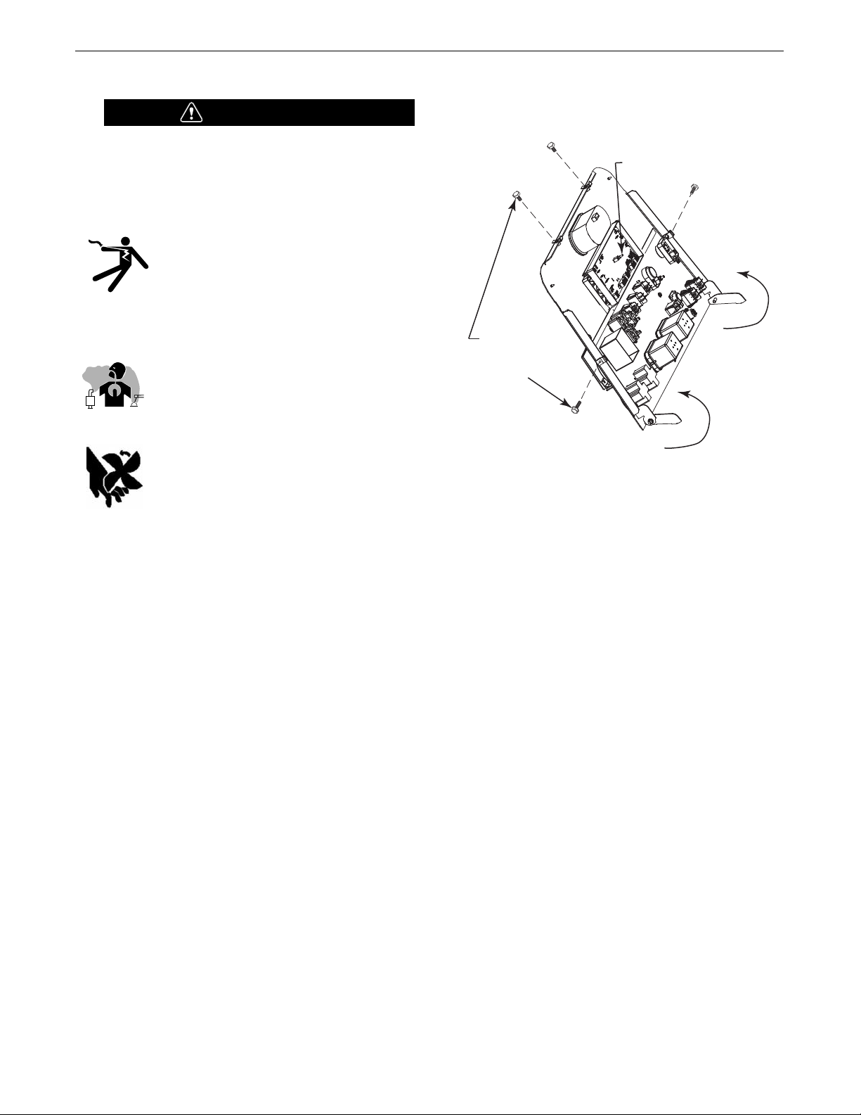
VANTAGE® 600 SD
ON / OFF VDR SWITCH
REMOVE 4 SIDE
PANEL SCREWS
TO ACCESS (VRD)
SWITCH
FRONT PANEL
ROTATES AWAY FROM
THE FRONT PART OF WELDER
INSTALLATION
SAFETY PRECAUTIONS
WARNING
Do not attempt to use this equipment until you have thoroughly read all operating and maintenance manuals supplied
with your machine. They include important safety precautions, detailed engine starting, operating and maintenance
instructions and parts lists.
ELECTRIC SHOCK can kill.
• Do not touch electrically live parts such as
output terminals or internal wiring.
• Insulate yourself from the work and ground.
• Always wear dry insulating gloves.
------------------------------------------------------------------
ENGINE EXHAUST can kill.
• Us e in o pen, w e ll ven t ilated are as or vent
exhaust outside
------------------------------------------------------------------
MOVING PARTS can injure.
• Do not operate with doors open or guards off.
• Stop engine before servicing.
• Keep away from moving parts
------------------------------------------------------------------
Only qualified personnel should install, use or service this
equipment.
VRD (VOLTAGE REDUCTION DEVICE)
With the VRD switch in the “OFF” position, the VRD lights are non activated.
FIGURE A.1
LOCATION AND VENTILATION
The welder should be located to provide an unrestricted flow of
clean, cool air to the cooling air inlets and to avoid restricting the
cooling air outlets. Also, locate the welder so that the engine
exhaust fumes are properly vented to an outside area.
The VRD reduces the OCV (Open Circuit Voltage) at the welding output
terminals while not welding to less than 30VDC when the resistance of
the output circuit is above 200Ω (ohms).
The VRD requires that the welding cable connections be kept in good
electrical condition because poor connections will contribute to poor
starting. Having good electrical connections also limits the possibility of
other safety issues such as heat-generated damage, burns and fires.
The machine is shipped with the VRD switch in the “OFF” position. To
turn it “On” or “Off”:
• Turn the engine “Off”.
• Disconnect the negative battery cable.
• Lower the Front panel by removing 4 side panel screws.
(See Figure A.1)
• Place the VRD switch in the “On” or “Off” position. (See Figure
A.1)
DO NOT MOUNT OVER COMBUSTIBLE SURFACES
Where there is a combustible surface directly under stationary or fixed electrical equipment, that surface should be covered with a steel plate at least .06”(1.6mm) thick, which
should extend not less than 5.90”(150mm) beyond the equipment on all sides.
---------------------------------------------------------------------
STORING
1. Store the machine in a cool, dry place when it is not in use.
Protect it from dust and dirt. Keep it where it can’t be accidentally damaged from construction activities, moving vehicles, and other hazards.
2. Drain the engine oil and refill with fresh oil. Run the engine
for about five minutes to circulate oil to all the parts. See the
ENGINE OPERATION section manual for details on changing
oil.
3. Remove the battery, recharge it, and adjust the electrolyte
level. Store the battery in a dry, dark place.
STACKING
VANTAGE
®
600 SD machines cannot be stacked.
A-2
VANTAGE® 600 SD
INSTALLATION
ANGLE OF OPERATION
To achieve optimum engine performance the VANTAGE®600 SD
hould be run in a level position. The maximum angle of operation
s
for the Deutz engine is 30 degrees in all directions. When operating the welder at an angle, provisions must be made for checking
and maintaining the oil level at the normal (FULL) oil capacity. Also
he effective fuel capacity will be slightly less than the specified
t
25 gal.(94.6 ltrs.)will be slightly less than the amount specified.
LIFTING
The VANTAGE
with a full tank of fuel and 1662lbs. (753kg) less fuel. A lift bail is
mounted to the machine and should always be used when lifting
the machine.
®
600 SD weighs approximately 1836lbs. (832kg)
WARNING
• Lift only with equipment of adequate lifting capacity.
• Be sure machine is stable when lifting.
• Do not lift this machine using lift bale if it
is equipped with a heavy accessory such
as trailer or gas cylinder.
FALLING • Do not lift machine if lift bale is
EQUIPMENT can damaged.
cause injury. • Do not operate machine while
suspended from lift bale.
------------------------------------------------------------------
HIGH TEMPERATURE OPERATION
At temperatures above 104°F (40°C), output voltage derating may
be necessary. For maximum output current ratings, derate welder
voltage rating 2 volts for every 21°F (10°C) above 104°F (40°C).
Cold weather starting:
With a fully charged battery and OW40 oil, the engine should start
satisfactorily down to -15°F(-26C°). If the engine must be frequently started at or below 0°F (-18°C), it may be desirable to
install cold-starting aides. For engines with common rail injection,
the mixing of petroleum or kerosene and adding of extra low additives is not permissible. Fuels in accordance with ASTM S975
Grade 1D or DIN EN590-Arctic-Diesel may have no petroleum
added. Allow the engine to warm up before applying a load or
switching to high idle.
WARNING
Under no conditions should ether or other starting fluids be
used with this engine!
------------------------------------------------------------------
HIGH ALTITUDE OPERATION
At higher altitudes, output derating may be necessary. For maximum
rating, derate the welder output in accordance with the guidelines in
Table A.1 below for this engine model from the manufacturer:
TABLE A.1 DEUTZ D 2.9 L4
METERS FEET AVAILABLE (%)
ALTITUDE MAXIMUM POWER
0-750 0-2461 99
1000 3281 95
2000 6562 95
3000 9842 93
4000 13123 88
5000 16404 74
6000 19685 60
A-3

VANTAGE® 600 SD
INSTALLATION
TOWING
se a recommended trailer for use with this equipment for road, in-plant and
U
yard towing by a vehicle
assume responsibility that the method of attachment and usage does not
result in a safety hazard or damage the welding equipment. Some of the factors to be considered are as follows:
1. Design capacity of trailer vs. weight of Lincoln equipment and likely additional attachments.
2. Proper support of, and attachment to, the base of the welding equipment so
there will be no undue stress to the framework.
3. Proper placement of the equipment on the trailer to insure stability side to
side and front to back when being moved and when standing by itself while
being operated or serviced.
4. Typical conditions of use, i.e., travel speed; roughness of surface on which
the trailer will be operated; environmental conditions; like maintenance.
5. Conformance with federal, state and local laws.
(1)
Consult applicable federal, state and local laws regarding specific requirements for use on
public highways.
1)
(
. If the user adapts a non-Lincoln trailer, they must
(1)
VEHICLE MOUNTING
WARNING
Improperly mounted concentrated loads may cause unstable
vehicle handling and tires or other components to fail.
OIL
The VANTAGE®600 SD is shipped with the engine crankcase filled with high
quality SAE 10W-30 Oil that meets
engines. Check the oil level before starting the engine. If it is not up to the full
ark on the dip stick, add oil as required. Check the oil level every four hours
m
of running time during the first 50 running hours. Refer to the engine
Operator’s Manual for specific oil recommendations and break-in information.
The oil change interval is dependent on the quality of the oil and the operating
environment. Refer to the Engine Operator’s Manual for more details on the
proper service and maintenance intervals.
(API class CJ-4 or better)
for diesel
FUEL
USE DIESEL FUEL ONLY-
Ultra low sulphur fuel only.
WARNING
• Fill the fuel tank with clean, fresh fuel. The capacity of the tank is
25 gals. (94.6 ltrs). When the fuel gauge reads empty the tank
contains approximately 2 gals. (7.6 ltrs.) of reserve fuel.
NOTE: A fuel shut off valve is located just before the pre-filter/sedi-
ment filter. Place the valve in the closed position when the
welder is not used for extended periods of time.
------------------------------------------------------------------------
• Only transport this Equipment on serviceable vehicles
which are rated and designed for such loads.
• Distribute, balance and secure loads so vehicle is stable
under conditions of use.
• Do not exceed maximum rated loads for components such
as suspension, axles and tires.
• Mount equipment base to metal bed or frame of vehicle.
• Follow vehicle manufacturer’s instructions.
------------------------------------------------------------------
PRE-OPERATION ENGINE SERVICE
READ the engine operating and maintenance instructions supplied
with this machine.
WARNING
• Stop engine and allow to cool before fueling.
• Do not smoke when fueling.
• Fill fuel tank at a moderate rate and do not overfill.
• Wipe up spilled fuel and allow fumes to clear before starting engine.
• Keep sparks and flame away from tank.
------------------------------------------------------------------
FUEL CAP
Remove the plastic cap covering from the Fuel Tank Filler neck
and install the Fuel Cap.
WARNING
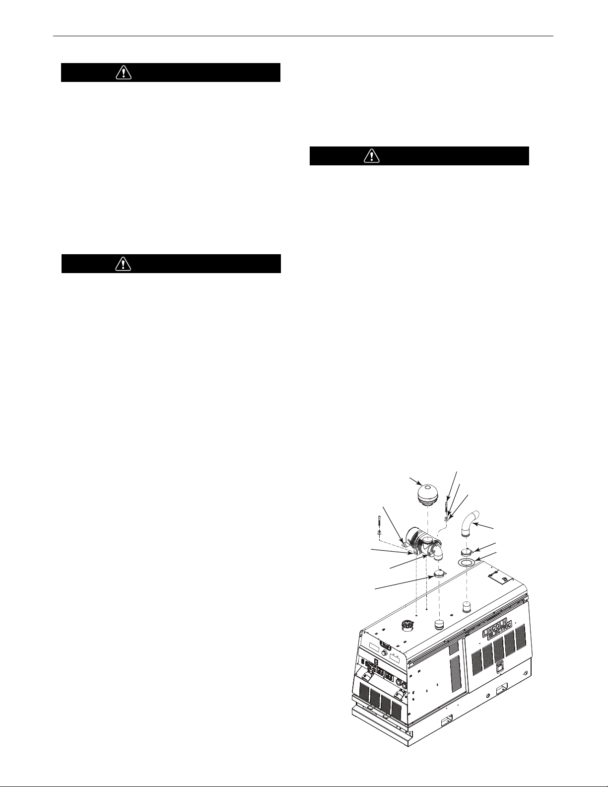
ENGINE COOLING SYSTEM
Air to cool the engine is drawn in the side and exhausted through
radiator and case back. It is important that the intake and exhaust
air is not restricted. Allow a minimum clearance of 1ft. (0.6m) from
the case back and 16 in. (406mm) from either side of the base to a
vertical surface. (Failure to resolve these guidelines may result in an
overtemp condition resulting in engine shut down).
------------------------------------------------------------------------
A-4
VANTAGE® 600 SD
SERVICE INDICATOR
AIR HOSE CLAMP
MOUNTING BRACKET
EXHAUST OUTLET
CLAMP
SEAL
(5/16-18x 1.25 HHCS) (2)
(LOCK WASHER) (2)
(MAIN WASHER) (2)
VACUATOR VALVE
INLET HOOD
INSTALLATION
BATTERY CONNECTION
CAUTION
Use caution as the electrolyte is a strong acid that can burn skin
and damage eyes.
------------------------------------------------------------------------
The
VANTAGE®600 SD
is shipped with the negative battery cable disconnected. Make certain that the RUN-STOP switch is in the STOP position.
Remove the two screws from the battery tray using a screwdriver or a
3/8"(10mm) socket. Attach the negative battery cable to the negative
battery terminal and tighten using a 1/2"(13mm) socket or wrench.
NOTE: This machine is furnished with a wet charged battery; if
unused for several months, the battery may require a booster
charge. Be careful to charge the battery with the correct polarity.
(See Battery in “Maintenance Section”)
WARNING
GASES FROM BATTERY can explode.
• Keep sparks, flame and cigarettes away from battery.
To prevent EXPLOSION when:
• INSTALLING A NEW BATTERY — disconnect negative cable
from old battery first and connect to new battery last.
• CONNECTING A BATTERY CHARGER — remove battery
from welder by disconnecting negative cable first, then
positive cable and battery clamp. When reinstalling, connect negative cable last. Keep well ventilated.
• USING A BOOSTER — connect positive lead to battery first
then connect negative lead to negative battery lead at
engine foot.
SPARK ARRESTOR
ome federal, state or local laws may require that gasoline or
S
diesel engines be equipped with exhaust spark arresters when
hey are operated in certain locations where unarrested sparks
t
may present a fire hazard.
The DOC (Diesel Oxidation Catalyst) unit included with this
elder qualifies as a spark arrester.
w
WARNING
An incorrect spark arrestor may lead to damage to the
engine or adversely affect performance.
-----------------------------------------------------------------
AIR CLEANER INSTALL
All parts below are shipped with the machine in a separate box
attached to the crate.(See Figure A.2)
• Remove cap from air intake hose and DOC exhaust attached on
machine. Insert air cleaner into bracket between the two
ridges of a larger diameter. Position the end cap so that “Top”
is at 9 o’clock.
• Remove plug and install service indicator, use thread sealant
or tape on pipe threads.
• Tighten air hose clamp just below service indicator to hold
clamp while pushing air cleaner onto hose, once hose is in
place loosen air hose clamp slide down and tighten clamp.
• Install 2 hex head screws, washers to mounting bracket
securing air cleaner.
• SERVICE INDICATOR
Air cleaner service indicator provides a Go/No-Go visual
indication of useful filter service life.
FIGURE A.2
BATTERY ACID can burn eyes and skin.
• Wear gloves and eye protection and be careful when
working near battery.
• Follow instructions printed on battery.
----------------------------------------------------------------
IMPORTANT: To prevent ELECTRICAL DAMAGE WHEN:
a) Installing new batteries.
b) Using a booster.
Use correct polarity — Negative Ground.
EXHAUST OUTLET PIPE
Remove cap from DOC pipe protruding from roof.
Using the clamp provided secure the outlet pipe to the outlet
tube with the pipe positioned such that it will direct the exhaust
in the desired direction away from the air intake. Tighten using a
1/4"(6mm) internal socket or allen wrench. Torque to
106in.lbs.(9ft.-lbs.)(12N-M)
A-5

VANTAGE® 600 SD
** Tabled values are for opera tion at ambient temperatures of 104°F (40°C) and below. Applications above
104°F (40°C) may require cables larger than recommended, or cables rated higher than 167°F (75°C).
200
200
250
250
250
250
300
300
350
400
400
500
600
600
600
Amperes
0 to 50 Ft. 50 to 100 Ft. 100 to 150 Ft. 150 to 200 Ft. 200 to 250 Ft.
Percent Duty
C
ycle
CABLE SIZES FOR COMBINED LENGTHS OF ELECTRODE AND WORK
CABLES [RUBBER COVERED COPPER - RATED 167°F (75°C)]**
60
100
30
40
60
100
60
100
40
60
100
60
60
80
100
2
2
3
2
1
1
1
2/0
1/0
2/0
3/0
2/0
3/0
2-1/0
2-1/0
2
2
3
2
1
1
1
2/0
1/0
2/0
3/0
2/0
3/0
2-1/0
2-1/0
2
2
2
1
1
1
1
2/0
2/0
2/0
3/0
3/0
3/0
2-1/0
2-1/0
1
1
1
1
1
1
1/0
2/0
2/0
3/0
3/0
3/0
4/0
2-2/0
2-2/0
1/0
1/0
1/0
1/0
1/0
1/0
2/0
3/0
3/0
4/0
4/0
4/0
2-3/0
2-3/0
2-3/0
O
UTPUT CABLE GUIDELINES
INSTALLATION
REMOTE CONTROL
he VANTAGE
T
nector. To enable remote control capabilities, the LOCAL/REMOTE
switch must be in the REMOTE position.
or the DOWNHILL PIPE or CC-STICK weld mode selector switch
F
positions, remote setting of the preset arc current is set through the 12
pin connector or the 14 pin connector depending on the setup menu
setting (12 pin connector is the factory default setting). The OUTPUT
CONTROL knob is used to set the maximum arc current preset range
for the remote input. The left display will show the arc current preset.
For the TOUCH START TIG weld mode selector switch position,
remote setting of the preset arc current is set through the 12 pin connector (typically using a foot Amptrol). The OUTPUT CONTROL knob is
used to set the maximum arc current preset range for the remote
input. The left display will show the maximum setting for the arc
current preset range as set by the OUTPUT CONTROL knob.
EXAMPLE: When the OUTPUT CONTROL on the welder is set to
200 amps, the arc current preset range on the remote control will
preset over the range from minimum to 200 amps, rather than the
full minimum to maximum preset arc current range. Any preset
arc current range that is less than the full range provides finer arc
current preset resolution for more fine tuning of the output.
®
00 SD is equipped with a 12-pin and a 14-pin con-
6
WELDING OUTPUT CABLES
With the engine off, route the electrode and work cables through the
strain relief bracket provided on the front of the base and connect to the
terminals provided. These connections should be checked periodically
nd tightened if necessary.
a
Listed in Table A.2 are copper cable sizes recommended for the rated current and duty cycle. Lengths stipulated are the distance from the welder to
work and back to the welder again. Cable sizes are increased for greater
lengths primarily for the purpose of minimizing cable voltage drop.
TABLE A.2
For the ARC GOUGING weld mode selector switch position, remote set-
ting of the preset arc current is set through the 12 pin connector. The
remote input sets the arc current preset over the full range from minimum to maximum. The left display will show the arc current preset.
For operation with a control cable wire feeder:
With the CV-WIRE weld mode selector switch position and the
WELD TERMINALS ON switch in the REMOTE position, remote
setting of the preset arc voltage is set through the 14 pin connector. The remote input sets the arc voltage preset range from
10.0V to 45.0V. The right display will show the arc voltage preset.
For operation with an across the arc wire feeder (for example,
an LN-25 PRO):
With the CV-WIRE weld mode selector switch position and the
WELD TERMINALS ON switch in the ON position, remote setting
of the preset arc voltage is set through the 12 pin connector. The
remote input sets the arc voltage preset range from 10.0V to
45.0V. The right display will show the arc voltage preset.
For the ARCLINK weld mode selector switch position, remote
capability is possible only with an ArcLink compatible digital
remote control through the 12 pin connector.
NOTE: To connect accessories with a 6 pin connector, use the
-----------------------------------------------------------------
WELDING TERMINALS
The
welding terminals when in the "WELD TERMINALS ON" position or "cold"
welding terminals when in the "REMOTELY CONTROLLED" position. When in
ArcLink, the output of the weld terminals is controlled by the mode selected.
VANTAGE®600 SD
included 12-pin to 6-pin adaptor (K2909-1).
is equipped with a toggle switch for selecting "hot"
PULSE WELDING
W
hen pulse welding, always use 4/0 cable. The cables must be sized
based upon the peak current of the pulse waveform, not the average
current. Do not coil the electrode or work cable. Limit the combined
length of the electrode and work cable to 60 feet. Undersized cables,
coiled cables and long lengths all increase cable inductance and
lower pulse welding performance.
CABLE INSTALLATION
Install the welding cables to your
1. The engine must be OFF to install welding cables.
2. Remove the flanged nuts from the output terminals.
3. Connect the electrode holder and work cables to the weld output terminals.
The terminals are identified on the case front.
4. Tighten the flanged nuts securely.
5. Be certain that the metal piece you are welding (the “work”) is properly
connected to the work clamp and cable.
6. Check and tighten the connections periodically.
A-6
VANTAGE®600 SD
as follows.
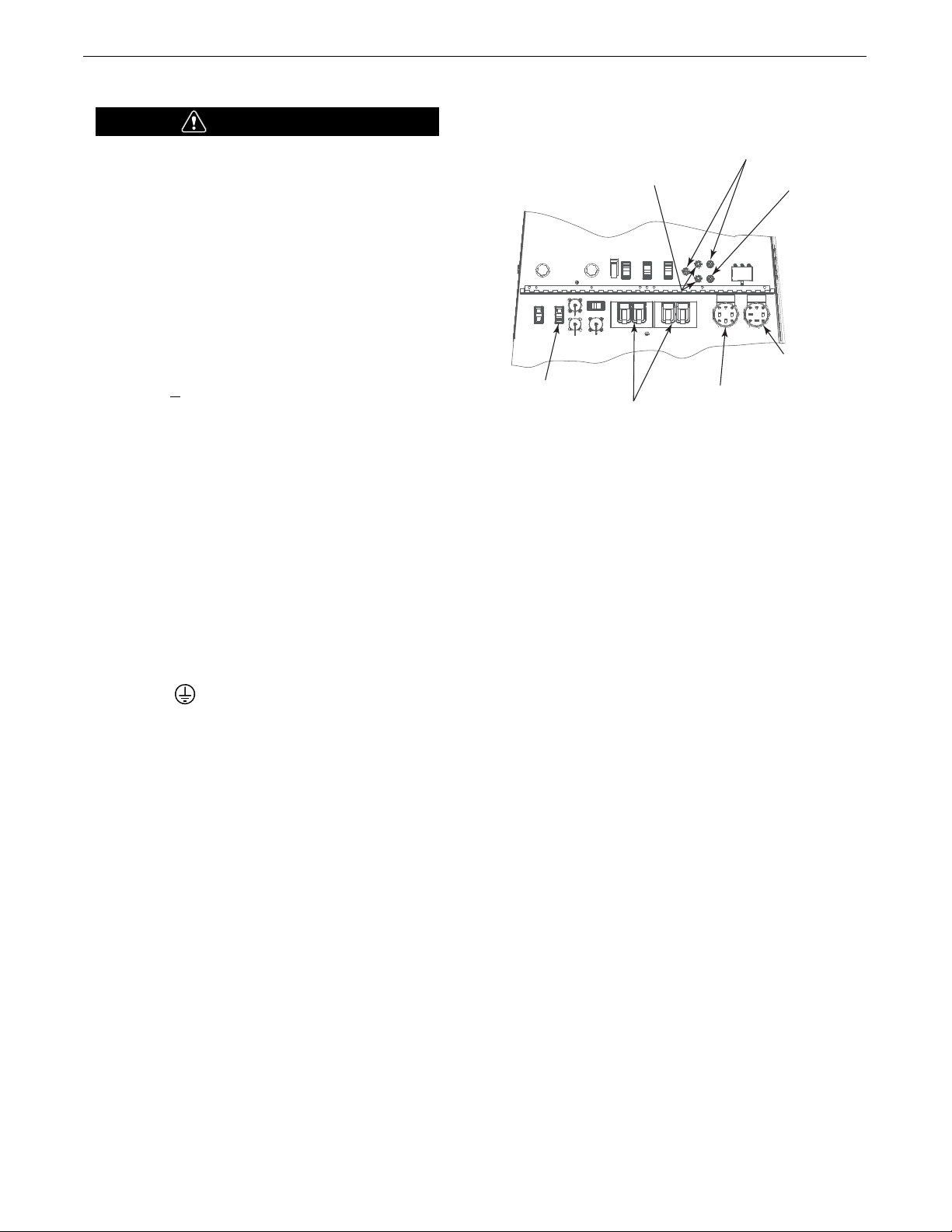
VANTAGE® 600 SD
240 VAC THREE
PHASE RECEPTACLE
120/240 VAC SINGLE
PHASE RECEPTACLE
CIRCUIT BREAKERS
IDLER SWITCH
BATTERY 20A BREAKER
10A 42V/40V ARCLINK BREAKERS
20A 120V AUXILIARY BREAKERS
AUXILIARY POWER RECEPTACLES
CAUTION
• Loose connections will cause the output terminals to overheat. The terminals may eventually melt.
• Do not cross the welding cables at the output terminal connection. Keep the cables isolated and separate from one another.
----------------------------------------------------
MACHINE GROUNDING
Because this portable engine driven welder creates its own power, it is
not necessary to connect its frame to an earth ground, unless the
machine is connected to premises wiring (home, shop, etc.).
To prevent dangerous electric shock, other equipment powered by this
engine driven welder must:
a) be grounded to the frame of the welder using a grounded type
plug, or
b) be double insulated.
When this welder is mounted on a truck or trailer, its frame must be
securely connected to the metal frame of the vehicle. When this engine
driven welder is connected to premises wiring such as that in a home or
shop, its frame must be connected to the system earth ground. See further connection instructions in the section entitled “Standby Power
Connections” as well as the article on grounding in the latest National
Electrical Code and the local codes.
In general, if the machine is to be grounded, it should be connected
with a #8 or larger copper wire to a solid earth ground such as a metal
ground stake going into the ground for at least 10Ft.(3.1m) or to the
metal framework of a building which has been effectively grounded.
The National Electric Code lists a number of alternate means of
grounding electrical equipment. A machine grounding stud marked
with the symbol is provided on the front of the welder.
INSTALLATION
FIGURE A.3
120 V DUPLEX RECEPTACLES AND GFCI
A GFCI protects the two 120V auxiliary power
receptacles.
A GFCI (Ground Fault Circuit Interrupter) is a device to protect against
electric shock should a piece of defective equipment connected to it
develop a ground fault. If this situation should occur, the GFCI will trip,
removing voltage from the output of the receptacle. If a GFCI is tripped
see the MAINTENANCE section for detailed information on testing and
resetting it. A GFCI should be properly tested at least once every month.
The 120 V auxiliary power receptacles should only be used with three
wire grounded type plugs or approved double insulated tools with two
wire plugs. The current rating of any plug used with the system must
be at least equal to the current capacity of the associated receptacle.
AUXILIARY POWER RECEPTACLES
Start the engine and set the “IDLE/RUN/STOP” control switch to the
“High Idle” mode. Voltage is now correct at the receptacles for auxiliary power. This must be done before a tripped GFCI can be reset
properly. See the MAINTENANCE section for more detailed information
on testing and resetting the GFCI.
The auxiliary power of the
Amp-120 VAC (5-20R) duplex receptacles with GFCI protection, one
50 Amp 120/240 VAC (14-50R) receptacle and one 50 Amp 240VAC
Three-Phase (15-50R) receptacle.
The auxiliary power capacity is 12,000 Watts Continuous of 60 Hz,
single phase power. The auxiliary power capacity rating in watts is
equivalent to volt-amperes at unity power factor. The max permissible
current of the 240 VAC output is 50amps.
The 240 VAC output can be split to provide two separate 120 VAC outputs with a max permissible current of 50 Amps per output to two separate 120 VAC branch circuits (these circuits cannot be paralleled).
Output voltage is within ± 10% at all loads up to rated capacity.
The Three-Phases auxiliary power capacity is 20,000 watts continuous. The maximum current is 50 amps.
VANTAGE®600 SD consists of two 20
NOTE: The 240 V receptacle has two 120 V circuits, but are of opposite polarities and cannot be paralleled.
All auxiliary power is protected by circuit breakers. The 120V has 20 Amp
circuit breakers for each duplex receptacle. The 120/240V Single Phase
and the 240V Three-Phases have a 50 Amp 3-pole Circuit Breaker that
disconnects both hot leads and all Three Phases simultaneously. (See
Figure A.3)
A-7
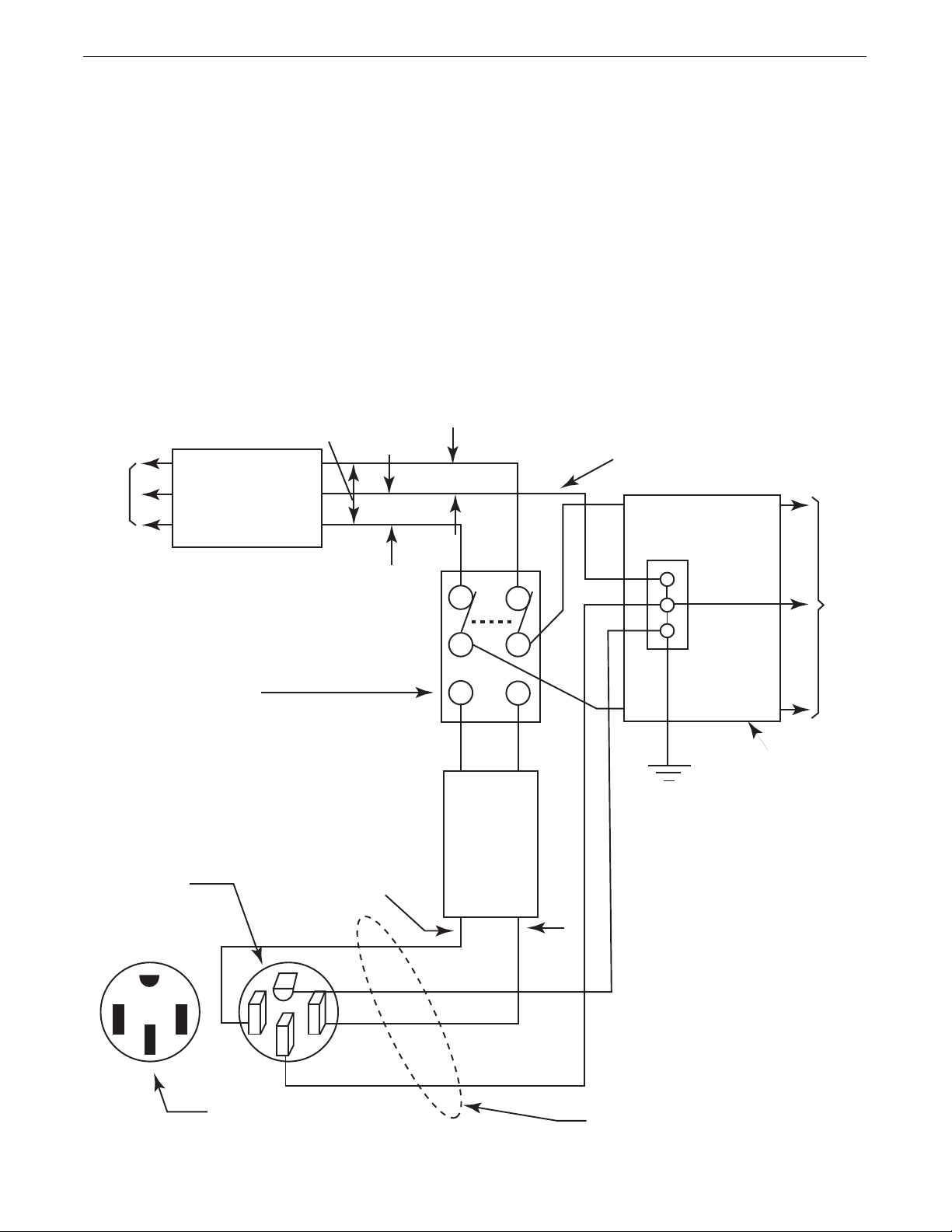
VANTAGE® 600 SD
60 Hz.
3-Wire
POWER
COMPANY
METER
240 VOLT
120 VOLT
120 VOLT
LOAD
N
NEUTRAL
BUS
GROUND
PREMISES
DISCONNECT AND
SERVICE
OVERCURRENT
PROTECTION
GND
N
NOTE: No. 6 COPPER CONDUCTOR CABLE SEE
NATIONAL ELECTRICAL CODE FOR ALTERNATE WIRE
SIZE RECOMMENDATIONS.
240 VOLT
GROUNDED CONDUCTOR
50AMP
240 VOLT
DOUBLE
POLE
CIRCUIT
BREAKER
DOUBLE POLE DOUBLE THROW
SWITCH RATING TO BE THE SAME
AS OR GREATER THAN PREMISES
SERVICE OVERCURRENT
PROTECTION.
50 AMP, 120/240
VOLT PLUG
NEMA TYPE 14-50
50 AMP, 120/240 VOLT
RECEPTACLE
STANDBY POWER CONNECTIONS
INSTALLATION
The VANTAGE®600 SD is suitable for temporary, standby or
emergency power using the engine manufacturer’s recommended
maintenance schedule.
The VANTAGE®600 SD can be permanently installed as a standby
power unit for 240 volt-3 wire, 50 amp service. Connections must
e made by a licensed electrician who can determine how the
b
120/240 VAC power can be adapted to the particular installation
and comply with all applicable electrical codes. Refer to the connection diagram shown in Figure A.4.
1. Install the double-pole, double-throw switch between the power
company meter and the premises disconnect. Switch rating
must be the same or greater than the customer’s premises disconnect and service over current protection.
FIGURE A.4 Connection of the VANTAGE® 600 SD to Premises Wiring
2. Take necessary steps to assure load is limited to the capacity of
®
the VANTAGE
600 SD by installing a 50 amp, 240 VAC double
pole circuit breaker. Maximum rated load for each leg of the 240
VAC auxiliary is 50 amps. Loading above the rated output will
reduce output voltage below the allowable -10% of rated voltage
hich may damage appliances or other motor-driven equipment
w
and may result in overheating of the VANTAGE
®
600 SD engine
and / or alternate windings.
3. Install a 50 amp 120/240 VAC plug (NEMA Type 14-50P) to the
double-pole circuit breaker using No. 6, 4 conductor cable of
the desired length.
4. Plug this cable into the 50 Amp 120/240 Volt receptacle on the
VANTAGE®600 SD case front.
A-8
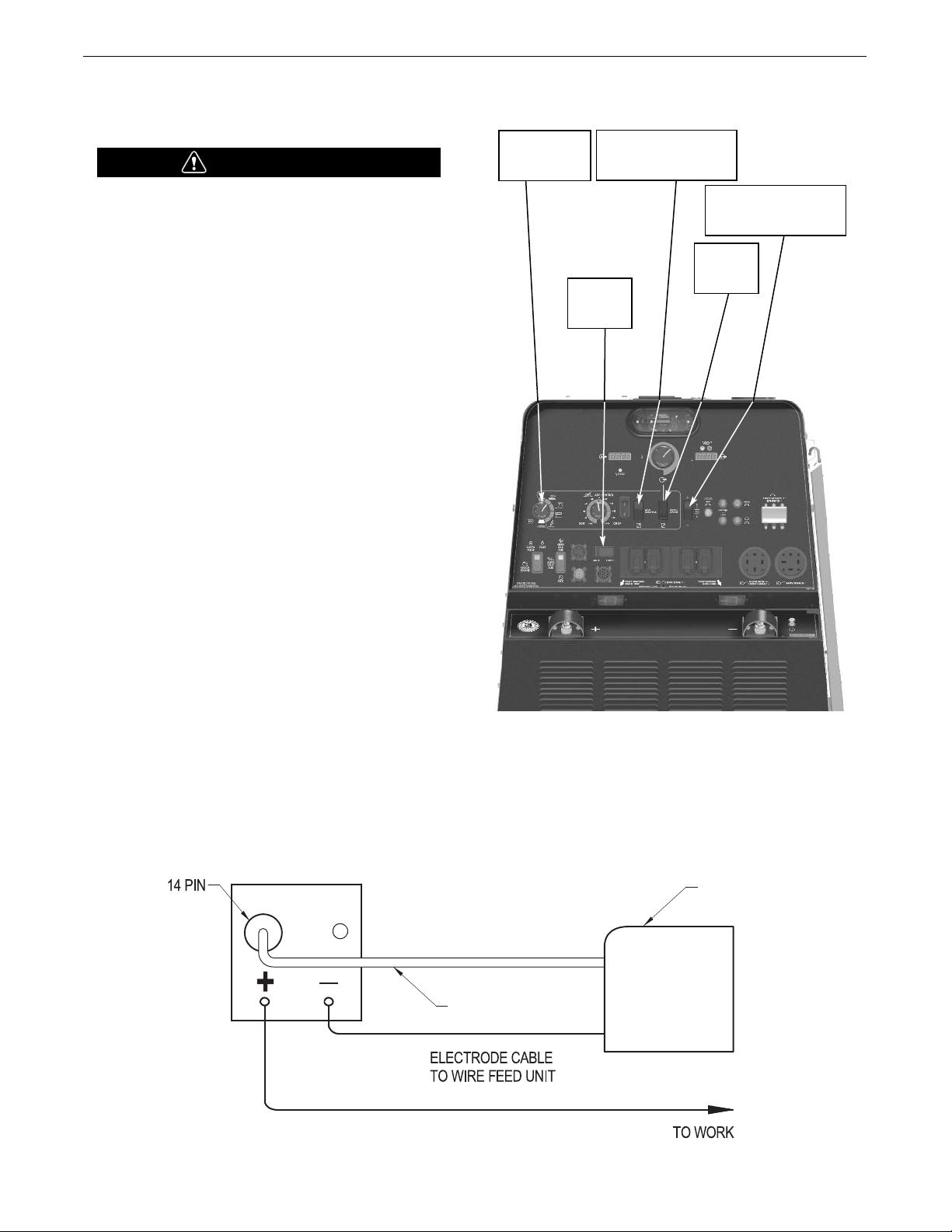
VANTAGE® 600 SD
WIRE FEEDER
ENGINE WELDER
K1797-xx
CABLE
Set Mode to
CV Wire
Set to
Remote
Set to
42V
Set Weld Terminals to
Remotely Controlled
Set Polarity to Match
Electrode Polarity
CONNECTION OF WIRE FEEDERS WITH CONTROL
CABLE (14 PIN)
WARNING
Shut off welder before making any electrical connections.
------------------------------------------------------------------
CONNECTION OF LF-72, LF-74, FLEX FEED 74 HT,
FLEX FEED 84, LN-25 PRO DUAL POWER TO THE
®
VANTAGE
• Shut the welder off.
• Set the “WIRE FEEDER VOLTMETER” switch to either “+” or “-”
as required by the electrode being used (See Figure A.5).
• For electrode Positive, connect the electrode cable to the "+" terminal of the welder and work cable to the "-" terminal of the welder.
For electrode Negative, connect the electrode cable "-" terminal of
the welder and work cable to the "+" terminal of the welder.
600 SD
IGURE A.5
F
INSTALLATION
• Set the “MODE” switch to the “CV-WIRE” position.
• Adjust the “ARC CONTROL” knob to desired Crispness. SOFT for
• Set the “WELDING TERMINALS” switch to the “REMOTELY
• Set the wire feeder voltage switch to 42V.
• Connect the 14 pin control cable from the wire feeder to the
• Set the “REMOTE/LOCAL” switch to “REMOTE” if the feeder is
MIG and CRISP for Innershield.
CONTROLLED” position.
engine drive (See Figure A.6).
equipped with a remote output control knob.
FIGURE A.6
A-9
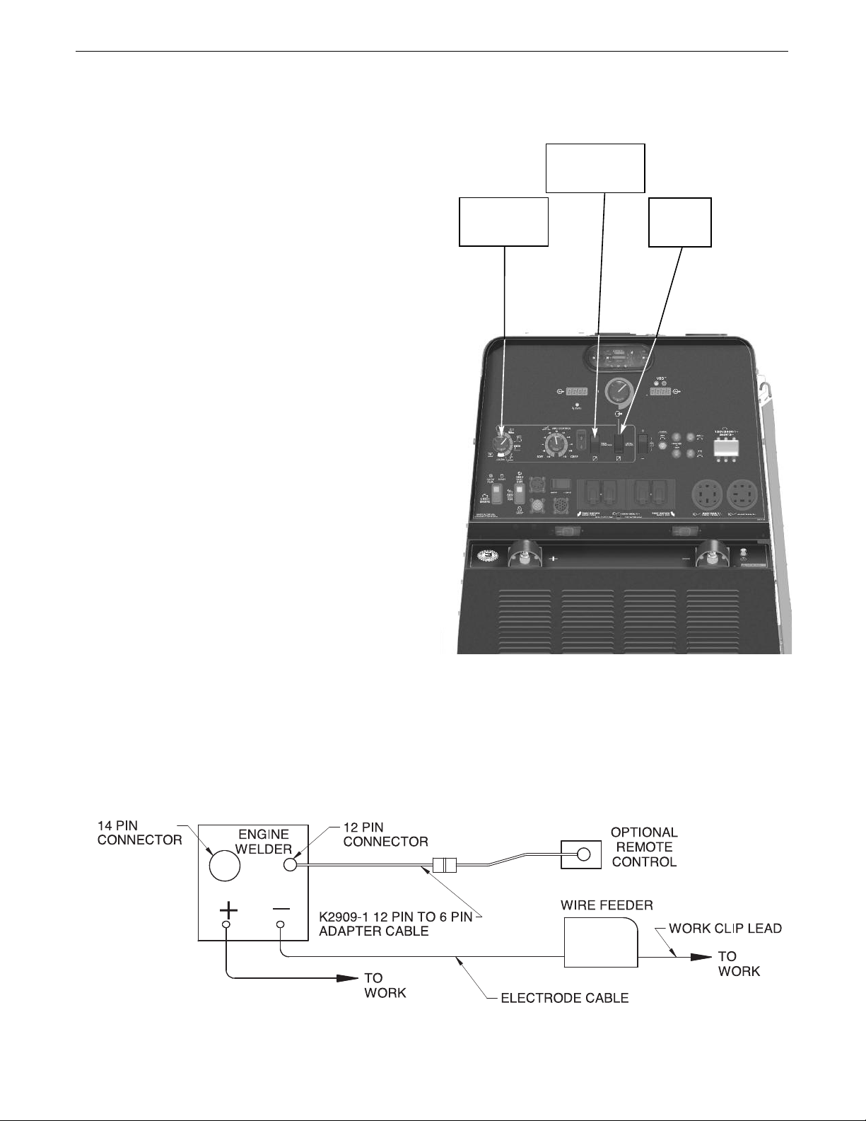
VANTAGE® 600 SD
Set Mode to
CV Wire
Set to
Local
Weld
Terminals On
INSTALLATION
CONNECTION OF ACROSS THE ARC WIRE FEEDERS
TO THE VANTAGE
hese connections instructions apply to both the LN-25 Pro and
T
Activ8 models. The feeders have an internal contactor and the
lectrode is not energized until the gun trigger is closed. When the
e
gun trigger is closed the wire will begin to feed and the welding
process is started.
• Shut the welder off.
• For electrode Positive, connect the electrode cable to the "+"
terminal of the welder and work cable to the "-" terminal of the
welder. For electrode Negative, connect the electrode cable "-"
terminal of the welder and work cable to the "+" terminal of the
welder.
• Attach the single lead from the front of the feeder to work using
the spring clip at the end of the lead. This is a control lead to
supply current to the wire feeder motor; it does not carry welding current (See Figure A.8).
• Set the MODE switch to the "CV-WIRE" position (See Figure A.7).
• Set the "WELD TERMINALS" switch to "WELD TERMINALS ON"
®
600 SD
FIGURE A.7
• Set the "ARC CONTROL" knob to "0" initially and adjust to suit.
• Set the “REMOTE/LOCAL” switch to “LOCAL” control.
FIGURE A.8
A-10
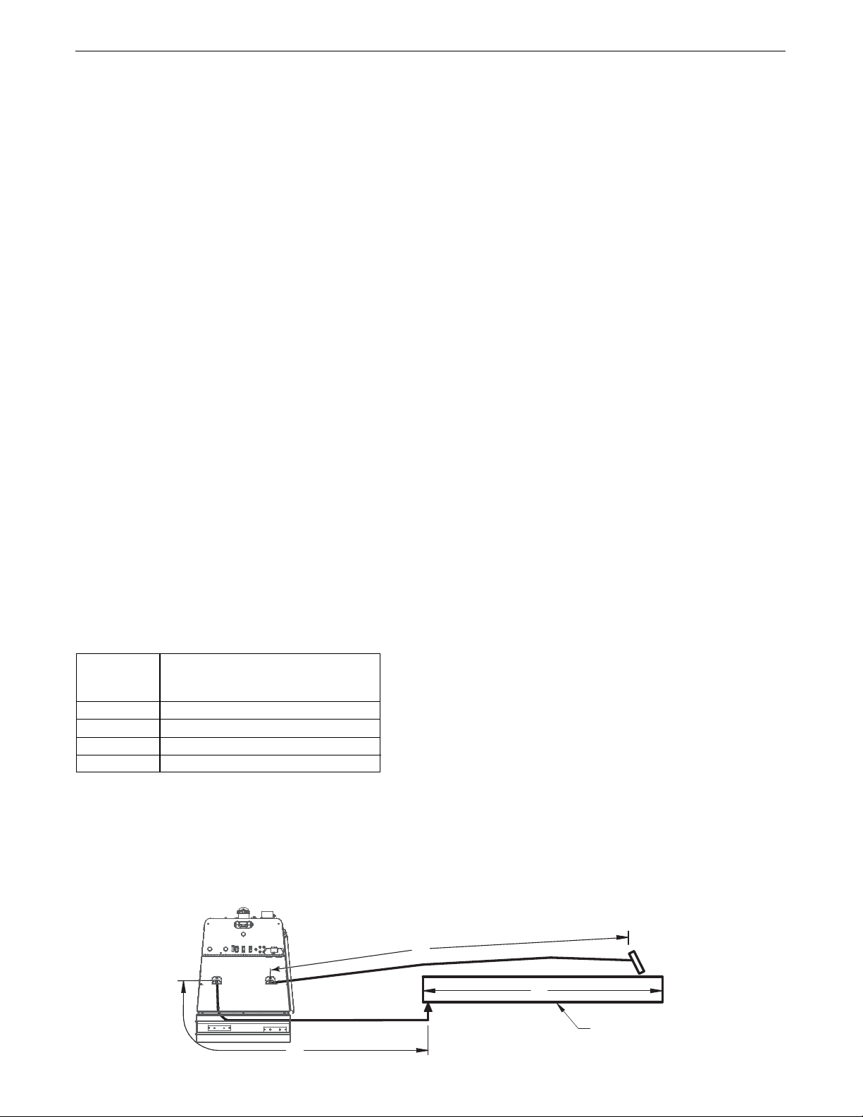
VANTAGE® 600 SD
B
A
C
WORK
VANTAGE
600 SD
®
INSTALLATION
CABLE INDUCTANCE AND ITS EFFECTS ON
WELDING
xcessive cable inductance will cause the welding performance to
E
degrade. There are several factors that contribute to the overall
nductance of the cabling system including cable size, and loop
i
area. The loop area is defined by the separation distance between
the electrode and work cables, and the overall welding loop
length. The welding loop length is defined as the total of length of
the electrode cable (A) + work cable (B) + work path (C) (See
Figure A.9).
To minimize inductance always use the appropriate size cables,
and whenever possible, run the electrode and work cables in close
proximity to one another to minimize the loop area. Since the most
significant factor in cable inductance is the welding loop length,
avoid excessive lengths and do not coil excess cable. For long
work piece lengths, a sliding ground should be considered to keep
the total welding loop length as short as possible.
Electrode Voltage Sensing
The remote ELECTRODE sense lead (67) is built into the 5-pin
ArcLink control cable and is always connected to the wire drive
feed plate when an ArcLink wire feeder is present. Enabling or
disabling electrode voltage sensing is application specific, and
automatically configured by the active weld mode.
Voltage sense leads requirements are based on the weld process
(See Table A.3)
TABLE A.3
Process
Electrode Voltage Sensing
67 lead
GMAW
FCAW
GTAW
SMAW
(1)
The electrode voltage sense lead (67) is automatically
enabled by the weld process, and integral to the 5 pin
ArcLink control cable
(K1543-xx) or K2683-xx.
Voltage sense at studs
Voltage sense at studs
67 lead
67 lead
(1)
CONTROL CABLE CONNECTIONS
General Guidelines
Genuine Lincoln control cables should be used at all times (except
here noted otherwise). Lincoln cables are specifically designed
w
for the communication and power needs of the
Power Feed™systems. Most are designed to be connected end to
end for ease of extension. Generally, it is recommended that the
total length not exceed 200ft. (60.960m). The use of non-standard
cables, especially in lengths greater than 25 feet, can lead to
communication problems (system shutdowns), poor motor acceleration (poor arc starting), and low wire driving force (wire feeding
problems). Always use the shortest length of control cable possible, and DO NOT coil excess cable.
Regarding cable placement, best results will be obtained when
control cables are routed separate from the weld cables. This minimizes the possibility of interference between the high currents
flowing through the weld cables, and the low level signals in the
control cables.
Product specific Installation Instructions
®
Connection Between VANTAGE
600 SD and ArcLink®Compatible
Wire feeders (K1543, K2683 – ArcLink®Control Cable)
The 5-pin ArcLink®control cable connects the VANTAGE®600 SD
to the wire feeder. The control cable consists of two power leads,
one twisted pair for digital communication, and one lead for voltage
sensing. The 5-pin ArcLink®connection on the VANTAGE®600 SD
is located on control panel. The control cable is keyed and polarized to prevent improper connection. Best results will be obtained
when control cables are routed separate from the weld cables,
especially in long distance applications. The recommended combined length of the ArcLink®control cable network should not
exceed 200ft. (60.960m).
Engine Welder and
FIGURE A.9
A-11

ANTAGE
V
®
00 SD
6
NOTES
A-12

ANTAGE
V
®
00 SD
6
OPERATION
SAFETY INSTRUCTIONS
ead and understand this entire section before operating
R
your VANTAGE
®
600 SD.
WARNING
o not attempt to use this equipment until you have thor-
D
oughly read all operating and maintenance manuals supplied
with your machine. They include important safety precautions, detailed engine starting, operating and maintenance
instructions and parts lists.
ELECTRIC SHOCK can kill.
• Do not touch electrically live parts such as
output terminals or internal wiring.
• Insulate yourself from the work and ground.
• Always wear dry insulating gloves.
-----------------------------------------------------------------
ENGINE EXHAUST can kill.
• Use in open, well ventilated areas or vent
exhaust outside
• Do not stack anything near the engine.
-----------------------------------------------------------------
MOVING PARTS can injure.
• Do not operate with doors open or guards
off.
• Stop engine before servicing.
• Keep away from moving parts
-----------------------------------------------------------------
Only qualified personnel should operate this equipment.
RECOMMENDED APPLICATIONS
WELDER
he VANTAGE
T
welding output for stick (SMAW) and TIG (GTAW) welding. The
VANTAGE
welding output for MIG (GMAW), Innershield (FCAW), Outershield
FCAW-G) and Metal Core (GMAW-C) welding. In addition the
(
VANTAGE
to 1/2”(13mm) in diameter.
The VANTAGE
®
00 SD provides excellent constant current DC
6
®
600 SD also provides excellent constant voltage DC
®
600 SD can be used for Arc Gouging with carbons up
®
600 SD is not recommended for pipe thawing.
GENERATOR
The
VANTAGE®600 SD
and 240V three phase output for auxiliary power and emergency standby
power.
provides smooth 120/240 VAC single phase
ADDITIONAL SAFETY PRECAUTIONS
Always operate the welder with the sliding door closed and
the side panels in place as these provide maximum protection
from moving parts and insure proper cooling air flow.
B-1

ANTAGE
V
®
00 SD
6
CONTROLS AND SETTINGS
All welder and engine controls are located on the case front panel.
Refer to Figure B.1 and the explanations that follow.
igure B.1 CASE FRONT PANEL CONTROLS
F
OPERATION
12
1
14
7
8
9
1
11
2
13
15
31
0
3
3a
3b
3c
3d
3e
4
5
6a
6
16
17
23
11a
19
20
21
22
18
24
ENGINE CONTROLS
1. STOP / (LOW IDLE/RUN) / (HIGH IDLE/RUN)
SWITCH
Toggling the switch to the RUN position energizes the fuel solenoid for approximately 30 seconds. The engine must be started
within that time or the fuel solenoid will degenerize, and the
switch must be toggled to reset the timer.
Has two positions as follows:
1) In the “High” position , the engine runs at the high idle
speed controlled by the governor.
2) In the “Auto” / position, the idler operates as
follows:
25
a. When switched from “High” to “Auto” or after starting the
engine, the engine will operate at full speed for approximately
12 seconds and then go to low idle speed.
b. When the electrode touches the work or power is drawn for
lights or tools (approximately 100 Watts minimum) the engine
accelerates and operates at full speed.
c. When welding ceases and the AC power load is turned off, a
fixed time delay of approximately 12 seconds starts.
d. If the welding or AC power load is not restarted before the end of the
time delay, the idler reduces the engine speed to low idle speed.
e. The engine will automatically return to high idle speed when the
welding load or A.C. power load is reapplied.
B-2

ANTAGE
V
dler Operational exceptions
I
®
00 SD
6
When the WELDING TERMINALS switch is in the “Remotely
Controlled” position or the MODE SELECTION switch is in the
®
ArcLink
position the idler will operate as follows:
• When the triggering device (Amptrol, Arc Start Switch, etc.) is
pressed the engine will accelerate and operate at full speed provided a welding load is applied within approximately 12 seconds.
If the triggering device remains pressed but no welding load is
•
applied within approximately 12 seconds the engine may
return to low idle speed.
• If the triggering device is released or welding ceases the
engine will return to low idle speed after approximately 12
seconds.
2. START SWITCH
Energizes the starter motor to crank the engine. With the engine
"Run / Stop" switch in the "Run" position, push and release the
Start button to start the engine:
• this switch has an amber light (Top of switch) to indicate
Glow light, this engine will automatically apply power to
the glow circuit and indicator light will turn off when glow
is completed. (Engine will crank but will not start until
glow cycle is completed)
• this switch also has a red light (Bottom of switch) it will
light up when there are faults with the engine. (Check
engine light comes on) Field Service Shop will need to
connect to diagnostic plug to read error codes.
OPERATION
4. OUTPUT CONTROL- The OUTPUT dial is used to preset the
output voltage or current as displayed on the digital meters for
he five welding modes.
t
5. VRD (Voltage Reduction Device) INDICATOR LIGHTS- O
®
front panel of the VANTAGE
when lit indicates OCV(Open Circuit Voltage) is equal to or greater than 30V
and a green light when lit indicates OCV(Open Circuit Voltage) is less than
30V.
The VRD “On/Off” switch inside the control panel must be “On” for the
VRD function to be active and the lights to be enabled. When the machine
is first started with VRD enabled, both lights will illuminate for 5 seconds.
These lights monitor the OCV(Open Circuit Voltage) and weld voltage at all
times. When not welding the green light will illuminate indicating that the
VRD has reduced the OCV to less than 30V. During welding the red light
will illuminate whenever the arc voltage is equal to or greater than 30V.
This means that the red and green light may alternate depending on the
weld voltage. This is normal operation.
If the red light remains illuminated or both VRD lights flash when not
welding, the VRD is not functioning properly. Please refer to your local
field service shop for service.
If the VRD is turned “On” and the lights don’t come “On”, refer to the trouble shooting section.
600 SD are two indicator lights. A red light
n the
3. DASH BOARD GAUGE
The dash board gauge displays 5 gauges:
3a. OIL PRESSURE
The gauge displays the engine oil pressure when the
engine is running.
3b. ENGINE TEMPERATURE
The gauge displays the engine coolant temperature.
3c. HOUR METER
The hour meter displays the total time that the engine
has been running. This meter is a useful indicator for
scheduling preventive maintenance.
3d. FUEL LEVEL
Displays the level of diesel fuel in the fuel tank.
The operator must watch the fuel level closely to
prevent running out of fuel and possibly having to
bleed the system.
3e. BATTERY VOLTAGE INDICATOR
Displays the battery voltage and indicates that the
charging system is functioning properly.
B-3
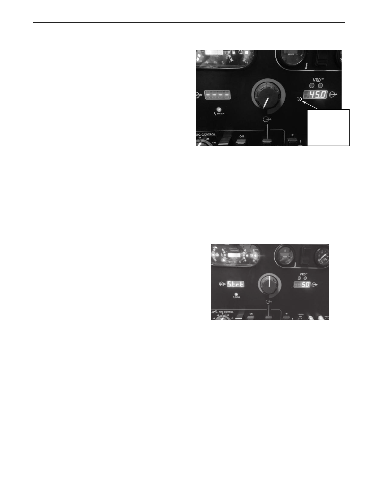
ANTAGE
HIDDEN SETUP MENU
ACCESS PORT:
INS ERT TOO L OR
PAPER CLIP
TO AC CESS
V
6.
®
00 SD
6
DIGITAL OUTPUT METERS-
The digital meters allow the
preset arc output voltage (CV-WIRE mode) or preset arc current
(CC-STICK, DOWNHILL PIPE, ARC GOUGING and TIG modes) to
e set prior to welding using the OUTPUT control dial. During
b
welding, the meter display the actual output voltage (VOLTS)
and current (AMPS). A memory feature holds the display of both
meters on for seven seconds after welding is stopped. This
allows the operator to read the actual current and voltage just
prior to when welding was ceased.
While the display is being held the left-most decimal point in
each display will be flashing. The accuracy of the meters is
+/- 3%.
OPERATION
FIGURE B.2
The meters will display all dashes for preset when ArcLink
®
mode is selected.
6a.
HIDDEN MENU BUTTON:
The hidden setup menu can be accessed any time the machine is on
with the engine running and not in a welding arc (arc off or OCV).
To access, press the hidden setup menu push button (Figure B.2.)
with the appropriate tool or paper clip, if no tool is readily available.
NOTE: The menu system will exit automatically if any of the following
conditions are met:
• If no settings are changed for 10 seconds.
• If the mode selection switch position is changed.
• If the arc status changes to arc or short.
• If the entire setup menu sequence is cycled through.
HIDDEN SETUP MENU FUNCTIONS
• Hot start setting individually settable by mode.
Hot start will not display if not applicable.
The left display will show “Hot” and “Strt” alternately at 0.5 second intervals. The right display will show a number from 0.0 to
10.0. The default value will be 5, (Figure B.3). This setting will be
stored in system memory and will be remembered between
machine power cycles.
FIGURE B.3
B-4

ANTAGE
FIGURE B.4 FIGURE B.5
FIGURE B.6
FIGURE B.7 FIGURE B.8
V
•
®
00 SD
6
Alternate CV mode selection. Default CV mode will be non-syner-
gic FCAW-SS (mode 6). Alternate settings will be non-synergic
GMAW (mode 5) and non-synergic FCAW-GS (mode 7). The left
display will show “CV” and “type” alternately at 0.5 second
intervals. The right display will show “FC.SS”(Figure B.4),
FC.gS”(Figure B.5) or “MIG”(Figure B.6). This setting will be
“
stored in system memory and will be remembered between
machine power cycles. This setting will only be visible if the
process selection switch is in the CV Wire position.
OPERATION
• Selection of the remote connector for stick (SMAW) modes. The
customer can select between the 12-pin or the 14-pin connector
for the remote potentiometer input when in the “remote” switch
position for stick (SMAW) modes. The default from the factory will
be the 12-pin connector. The left display will show “Pot”, “12P”
(Figure B.7) and the right display will show “Pot”, “14P” (Figure
B.8). This setting is stored in system memory and will be remembered between machine power cycles. This selection will only be
visible for stick (SMAW) modes.
B-5
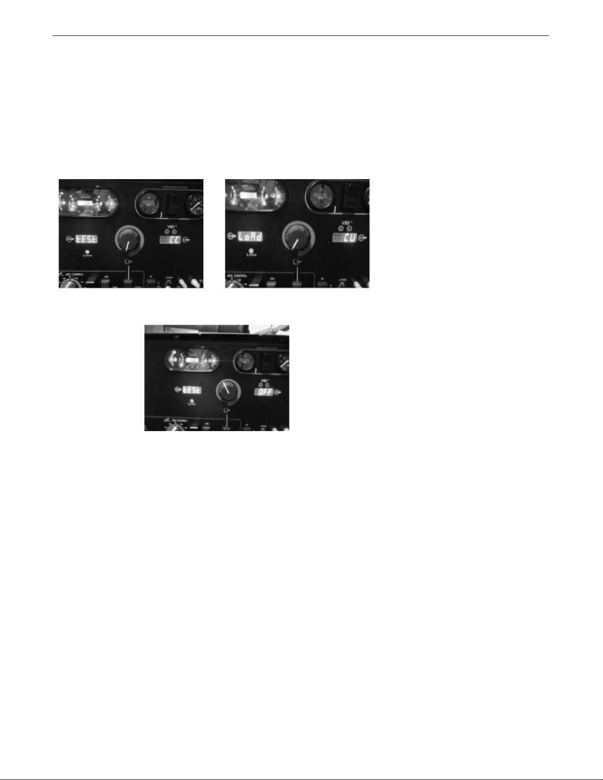
ANTAGE
FIGURE B.9 FIGURE B.10
FIGURE B.11
V
®
00 SD
6
• Test Modes for grid load testing. The left display will show “tESt”
nd “LoAd” alternately at 0.5 second intervals. The right display
a
will show “CC” (mode 200)(Figure B.9), “CV” (mode 201)(Figure
B.10) or “OFF” (normal operation)(Figure B.11). This setting is
not remembered between machine power cycles and will default
o OFF at each power on. Moving the position of the weld process
t
selection rotary switch Item 10 will reset the setting back to OFF.
OPERATION
EXITING
HIDDEN MENU BUTTON
Pressing and holding the hidden reset push button for 5 seconds will
cause certain stored values to be reset to defaults. The stored hot
start values will return to a default setting of 5 on the display (0 at the
attribute). The work point values will all be reset to the minimum
from the weld table for each respective weld mode. The alternate CV
mode selection will revert back to the Flux-Cored Arc Welding-Self
Shielding (FCAW-SS) setting. The remote pot connector choice will
revert back to the 12-pin connector. When the reset occurs, the left
display will show “ deF”, and the right display will show “AuLt” for 3
seconds until the machine exits the menu system.
B-6

ANTAGE
V
®
00 SD
6
OPERATION
7. WELD TERMINALS ON SWITCH
utput is enabled when in the ON position. Output is remotely controlled
O
when in the REMOTE position. This control is not active in
modes.
ArcLink
8. DOOR LATCH
9. ARC CONTROL
The ARC CONTROL knob is active in the CV-WIRE and CC-STICK modes,
and has different functions in these modes. This control is not active in
the TOUCH START TIG mode or in
CC-STICK mode: In this mode, the ARC CONTROL knob sets the short
circuit current (arc-force) during stick welding. Increasing the number
from -10(Soft) to +10(Crisp) increases the short circuit current and
prevents sticking of the electrode to the plate while welding.
This can also increase spatter. It is recommended that the ARC CONTROL be set to the minimum number without electrode sticking. Start
with a setting at 0.
DOWNHILL PIPE mode: In this mode, the ARC CONTROL knob sets the
short circuit current (arc-force) during stick welding to adjust for a soft
or a more forceful digging arc (Crisp).
ArcLink®mode.
13. 12-PIN CONNECTOR
®
For attaching optional remote control equipment. The
2909-1 (12-pin to 6-pin) adapter cable is included for
K
attaching to accessories requiring the 6-pin connector.
14. 14-PIN CONNECTOR
For attaching wire feeder control cables. Includes contactor closure circuit, work senselead remote control circuit, and 120VAC and 42VAC power.
15. WELD OUTPUT TERMINALS “+” POSITIVE AND “-” NEGATIVE
These 1/2” - 13 studs with flange nuts provide welding
connection points for the electrode and work cables. For
positive polarity welding the electrode cable connects to
the “+” positive terminal and the work cable connects to
this “-” negative terminal. For negative polarity welding
the work cable connects to the “+” positive terminal and
the electrode cable connects to this “-” negative terminal.
16. LOCAL/REMOTE SWITCH:
Increasing the number from -10(Soft) to +10(Crisp) increases the short
circuit current which results in a more forceful digging arc. Typically a
forceful digging arc is preferred for root and hot passes. A softer arc is
preferred for fill and cap passes where weld puddle control and deposition (“stacking” of iron) are key to fast travel speeds. It is recommended
that the ARC CONTROL be set initially at 0.
10. WELD MODE SELECTOR SWITCH:
(Provides six selectable welding modes)
CV-WIRE
DOWNHILL PIPE
CC-STICK
TOUCH START TIG
ARC GOUGES
ARC LINK
11.
42V / 115V WIRE FEEDER VOLTAGE SWITCH:
Toggles output of 14-pin connector to voltage requirement of Wire Feeder. (Located above 14-pin connector.)
In the LOCAL position, machine output control is set by
the Output Control knob on the front of the machine. In
the REMOTE position, the machine output control is set
by the remote inputs. This control is not active in
ArcLink® modes.
17. POLARITY SWITCH:
Matches the polarity of the wire feeder voltmeter to the
polarity of the electrode.
11a. 42V and 115V WIRE FEEDER BREAKERS
12. 5-PIN CONNECTOR
For attaching an
ArcLink®Wire Feeder control cable.
B-7

ANTAGE
V
18.
19. 50A 240V
®
00 SD
6
20A 120V AUXILIARY BREAKERS
3 PHASE BREAKER
20. BATTERY 20A BREAKER
21.
240VAC THREE PHASE RECEPTACLE
This is a 240VAC (15-50R) receptacle that provides
240VAC three phase auxiliary power. This receptacle has a 50 amp rating.
22. 120/240 VAC SINGLE PHASE RECEPTACLE
This is a 120/240VAC (14-50R) receptacle that provides 240VAC or
can be split for 120VAC single phase auxiliary power. This receptacle has a 50 amp rating. Refer to the AUXILIARY POWER RECEPTACLES section in the installation chapter for further information about
this receptacle. Also refer to the AUXILIARY POWER OPERATION section later in this chapter.
OPERATION
26. DIAGNOSTIC PLUG
his is used by Field Service shops to connect and trou-
T
bleshoot engine error codes and is found on the firewall
inside the machine on the service side. (Figure B.12)
IGURE B.12
F
26
Items 27 thru 30 are found inside the machine by
removing the right side panel facing the front.
(Figure B.13)
27. GLOW RELAY / BREAKER (70A)
28. FUEL RELAY / BREAKER (20A)
29. IDLE RELAY
30. ECU (Electronic Control Unit) BREAKER (30A)
23. 10A 42V/40V ARCLINK BREAKERS
CIRCUIT BREAKERS
24.
These circuit breakers provide separate overload current protection for each 120V circuit at the 240V single phase receptacle, each 120V single phase receptacle, the 240V three phase
receptacle, the 120VAC in the 14-Pin connector, the 42VAC in
the 14-Pin connector and battery circuit overload protection.
25. GROUND STUD
Provides a connection point for connecting the machine case
to earth ground. Refer to “MACHINE GROUNDING” in the
Installation chapter for proper machine grounding information.
FIGURE B.13
29
27
30
28
B-8
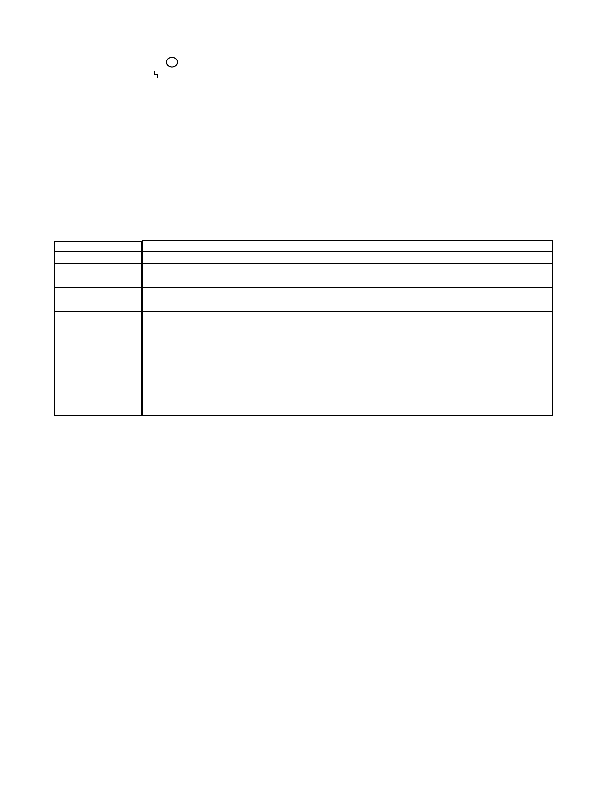
ANTAGE
V
®
00 SD
6
31. STATUS LED
(See Table B.1) Status
The status LED indicates system status. Normal operation is a steady green light.
Note: During normal power-up, the LED may flash red
and/or green as the equipment performs self
tests.
TABLE B.1
OPERATION
LED condition
Steady green
Blinking green.
Blin k ing gree n ,
fast
Blinking green followed by blinking
red.
Definition
System is communicating normally.
Occurs during a reset and indicates the power source is identifying each component in the system. This is
normal for up to 15 seconds after power-up, or if the system configuration is changed during operation.
Indicates that one or more pieces of ArcLink equipment are not mapping properly.
Non-recoverable system fault. If the power source or wire feeder status LED is flashing any combination of
red and green, errors are present in the system. Read the error code before the machine is turned off.
Instructions for reading the error code are detailed in the Service Manual. Individual code digits are flashed
in red with a long pause between digits. If more than one code is present, the codes will be separated by a
green light.
To clear the error, turn the power source OFF, and then back ON to reset.
B-9

VANTAGE® 600 SD
OPERATION
WELDER OPERATION
DUTY CYCLE
Duty cycle is the percentage of time the load is being applied in a 10
minute period. For example, a 60% duty cycle represents 6 minutes of
load and 4 minutes of no load in a 10 minute period.
STICK WELDING MODE
The
VANTAGE®600 SD
electrodes.
The MODE switch provides two stick welding settings as follows:
CC-STICK MODE
The CC-STICK position of the MODE switch is designed for horizontal, vertical-up and over head welding with all types of electrodes, especially low
hydrogen. The OUTPUT CONTROL knob adjusts the full output range for
stick welding.
The ARC CONTROL knob sets the short circuit (arc-force) current during
stick welding. Increasing the number from -10(Soft) to +10 (Crisp)
increases the short circuit current and prevents sticking of the electrode
to the plate while welding. This can also increase spatter. It is recommended that the ARC CONTROL be set to the minimum number without
electrode sticking. Start with the knob set at 0.
DOWNHILL PIPE MODE
This slope controlled setting is intended for “out-of-position” and “down
hill” pipe welding where the operator would like to control the current
level by changing the arc length. The OUTPUT CONTROL knob adjusts the
full output range for pipe welding.
The ARC CONTROL knob sets the short circuit current (arc-force) during
stick welding to adjust for a soft or a more forceful digging arc (Crisp).
Increasing the number from -10(Soft) to +10(Crisp) increases the short
circuit current which results in a more forceful digging arc. Typically a
forceful digging arc is preferred for root and hot passes. A softer arc is
preferred for fill and cap passes where weld puddle control and deposition (“stacking” of iron) are key to fast travel speeds. It is recommended
that the ARC CONTROL be set initially at 0.
can be used with a broad range of DC stick
TOUCH START TIG MODE
The
ing applications.
The TOUCH START TIG setting of the MODE switch is for DC TIG (Tungsten
Inert Gas) welding. To initiate a weld, the OUTPUT CONTROL knob is first
set to the desired current and the tungsten is touched to the work. During
the time the tungsten is touching the work there is very little voltage or
current and, in general, avoids tungsten contamination. Then, the tungsten is gently lifted off the work in a rocking motion, which establishes
the arc.
To stop the arc, simply lift the TIG torch away from the work piece. When
the arc voltage reaches approximately 30 volts, the arc will go out and the
machine will automatically reset to the touch start current level. The
tungsten may then be retouched to the work piece to restrike the arc. The
arc may also be started and stopped with an Amptrol or Arc Start Switch.
The ARC CONTROL is not active in the TIG mode.
In general the ‘Touch Start’ feature avoids tungsten contamination without the use of a Hi-frequency unit. If the use of a high frequency generator is desired, the K930-2 TIG Module can be used with the
VANTAGE®600 SD
The
cuitry for the connection of high frequency generating equipment.
The VANTAGE®600 SD and any high frequency generating equipment must be properly grounded. See the K930-2 TIG Module
operating manuals for complete instructions on installation, operation, and maintenance.
When using the TIG Module, the OUTPUT control on the
VANTAGE
RENT CONTROL on the TIG Module Amptrol.
VANTAGE®600 SD
VANTAGE®600 SD
®
600 SD is used to set the maximum range of the CUR-
can be used in a wide variety of DC TIG weld-
. The settings are for reference.
is equipped with the required R.F. bypass cir-
TYPICAL FUEL CONSUMPTION
Refer to Table B.2 for typical fuel consumption of the
Engine for various operating scenarios.
(Deutz TD 2.9 L4) Fuel Consumption
High Idle
Low Idle
100A 24V
200A 28V
300A 32V
400A 36V
500A 40V
Aux power 12,000VA single phase
Aux power 20,000VA three phase
VANTAGE®600 SD
Table B.2
GAL/HR
0.79
0.59
0.91
1.05
1.30
1.65
2.02
1.35
1.86
B-10
Liters/Hr
3.01
2.24
3.44
3.98
4.92
6.25
7.63
5.11
7.03
HRS @ 25 GAL(94.6L)
31.48
42.37
27.54
23.76
19.23
15.15
12.40
18.51
13.46
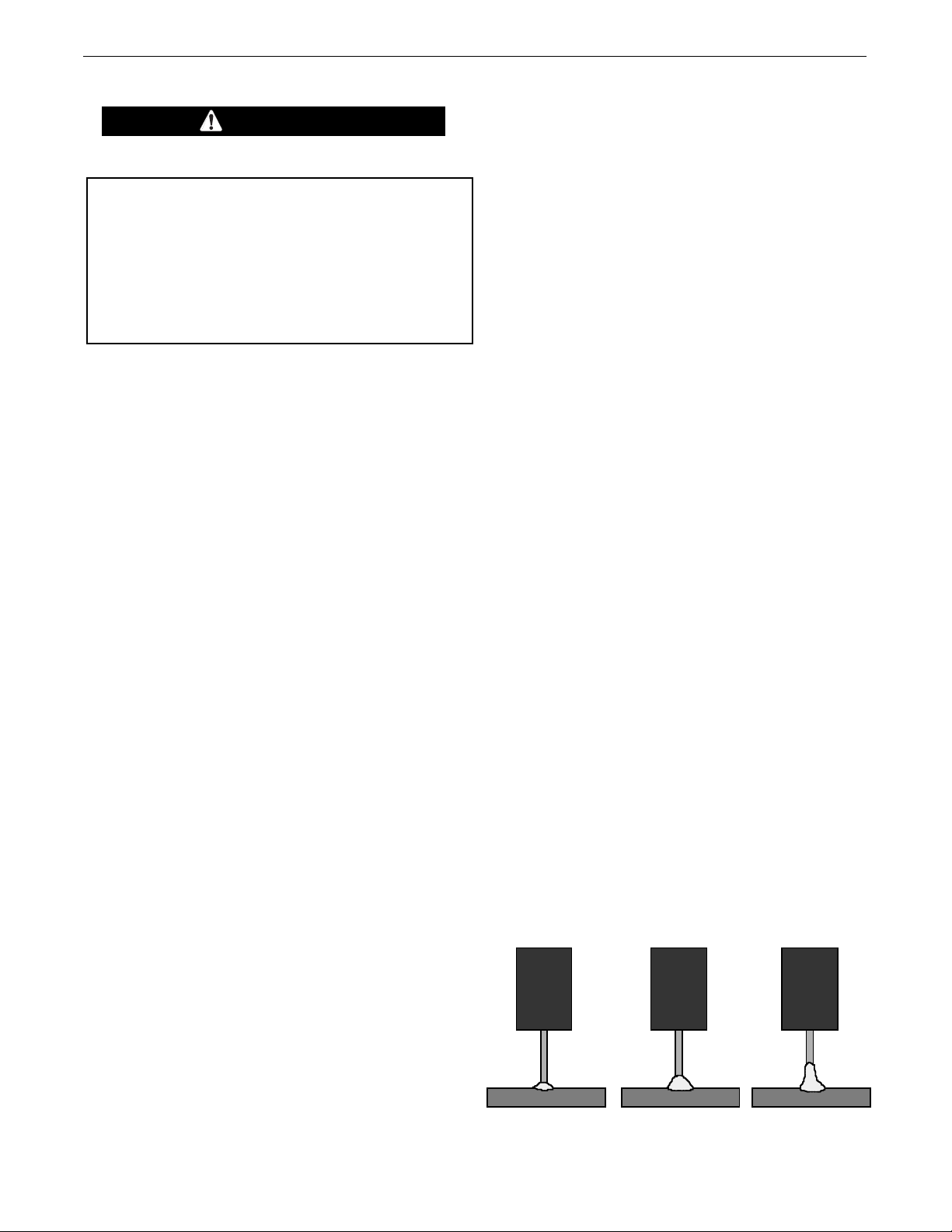
ANTAGE
Tr im . 50
Arc L en gt h Sh or t
Tr im 1 .00
Arc Length Medium
Trim 1.50
Arc L en gt h Lo ng
V
®
00 SD
6
OPERATION
COMMON WELDING PROCEDURES
WARNING
MAKING A WELD
The serviceability of a product or structure utilizing the welding
rograms is and must be the sole responsibility of the builder/user.
p
Many variables beyond the control of The Lincoln Electric Company
affect the results obtained in applying these programs. These
variables include, but are not limited to, welding procedure, plate
chemistry and temperature, weldment design, fabrication methods
and service requirements. The available range of a welding
program may not be suitable for all applications, and the build/user
is and must be solely responsible for welding program selection.
Choose the electrode material, electrode size, shielding gas, and process
(GMAW, GMAW-P etc.) appropriate for the material to be welded.
Select the weld mode that best matches the desired welding process.
The standard weld set shipped with the
encompasses a wide range of common processes that will meet
most needs. If a special weld mode is desired, contact the local
Lincoln Electric sales representative.
VANTAGE®600 SD
®
ANTAGE
V
current according to settings contained in the
00 SDthen uses the WFS setting to adjust the voltage and
6
VANTAGE®600 SD
.
In non-synergic modes, the WFS control behaves like a conventional
power source where WFS and voltage are independent adjustments.
Therefore, to maintain proper arc characteristics, the operator must
djust the voltage to compensate for any changes made to the WFS.
a
Amps
In constant current modes, this control adjusts the welding amperage.
Volts
In constant voltage modes, this control adjusts the welding voltage.
Trim
In pulse synergic welding modes, the Trim setting adjusts the arc
length. Trim is adjustable from 0.50 to 1.50. 1.00 is the nominal
setting and is a good starting point for most conditions.
UltimArc™ Control
UltimArc™ Control allows the operator to vary the arc characteristics. UltimArc™ Control is adjustable from –10.0 to +10.0 with
a nominal setting of 0.0.
All adjustments are made through the user interface. Because of the
different configuration options your system may not have all of the
following adjustments.
See Accessories Section for Kits and Options available to use with the
VANTAGE®600 SD
.
DEFINITION OF WELDING MODES
NON-SYNERGIC WELDING MODES
• A Non-synergic welding mode requires all welding process
variables to be set by the operator.
SYNERGIC WELDING MODES
• A Synergic welding mode offers the simplicity of single knob
control. The machine will select the correct voltage and amperage
based on the Wire Feed Speed (WFS) set by the operator.
BASIC WELDING CONTROLS
Weld Mode
Selecting a weld mode determines the output characteristics of the
VANTAGE®600 SD
a specific electrode material, electrode size, and shielding gas. For a
more complete description of the weld modes programmed into the
VANTAGE®600 SD
Guide supplied with the machine.
Wire Feed Speed (WFS)
In synergic welding modes (synergic CV, GMAW-P), WFS is the
dominant control parameter. The user adjusts WFS according to factors
such as wire size, penetration requirements, heat input, etc. The
power source. Weld modes are developed with
at the factory, refer to the Weld Set Reference
PULSE WELDING
Pulse welding procedures are set by controlling an overall “arc length”
variable. When pulse welding, the arc voltage is highly dependent upon
the waveform. The peak current, back ground current, rise time, fall
time and pulse frequency all affect the voltage. The exact voltage for a
given wire feed speed can only be predicted when all the pulsing
waveform parameters are known. Voltage or Trim can be adjusted.
Trim adjusts the arc length and ranges from 0.50 to 1.50 with a
nominal value of 1.00. Trim values greater than 1.00 increase the
arc length, while values less than 1.00 decrease the arc length.
(See Figure B.14)
FIGURE B.14
B-11
 Loading...