

Lincoln Electric VANTAGE 500-I Operator's Manual
Operator’s Manual
®
VANTAGE
500-I
For use with machines having Code Numbers:
11576, 11954, 11961, 12304
Register your machine:
www.lincolnelectric.com/register
Authorized Service and Distributor Locator:
www.lincolnelectric.com/locator
Save for future reference
Date Purchased
Code: (ex: 10859)
Serial: (ex: U1060512345)
IM10003-B | Issue D ate Jul-16
© Lincoln Global, Inc. All Rights Reserved.
Need Help? Call 1.888.935.3877
to talk to a Service Representative
Hours of Operation:
8:00 AM to 6:00 PM (ET) Mon. thru Fri.
After hours?
Use “Ask the Experts” at lincolnelectric.com
A Lincoln Service Representative will contact you
no later than the following business day.
For Service outside the USA:
Email: globalservice@lincolnelectric.com
THANK YOU FOR SELECTING
A QUALITY PRODUCT BY
LINCOLN ELEC TRIC.
PLEASE EXAMINE CARTON AND EQUIPMENT FOR
DAMAGE IMMEDIATELY
When this equipment is shipped, title passes to the purchaser
upon receipt by the carrier. Consequently, claims for material
damaged in shipment must be made by the purchaser against the
transportation company at the time the shipment is received.
SAFETY DEPENDS ON YOU
Lincoln arc welding and cutting equipment is designed and built
with safety in mind. However, your overall safety can be increased
by proper installation ... and thoughtful operation on your part.
DO NOT INSTALL, OPERATE OR REPAIR THIS EQUIPMENT
WITHOUT READING THIS MANUAL AND THE SAFETY
PRECAUTIONS CONTAINED THROUGHOUT. And, most importantly,
think before you act and be careful.
WARNING
This statement appears where the information must be followed
exactly to avoid serious personal injury or loss of life.
CAUTION
This statement appears where the information must be followed
to avoid minor personal injury or damage to this equipment.
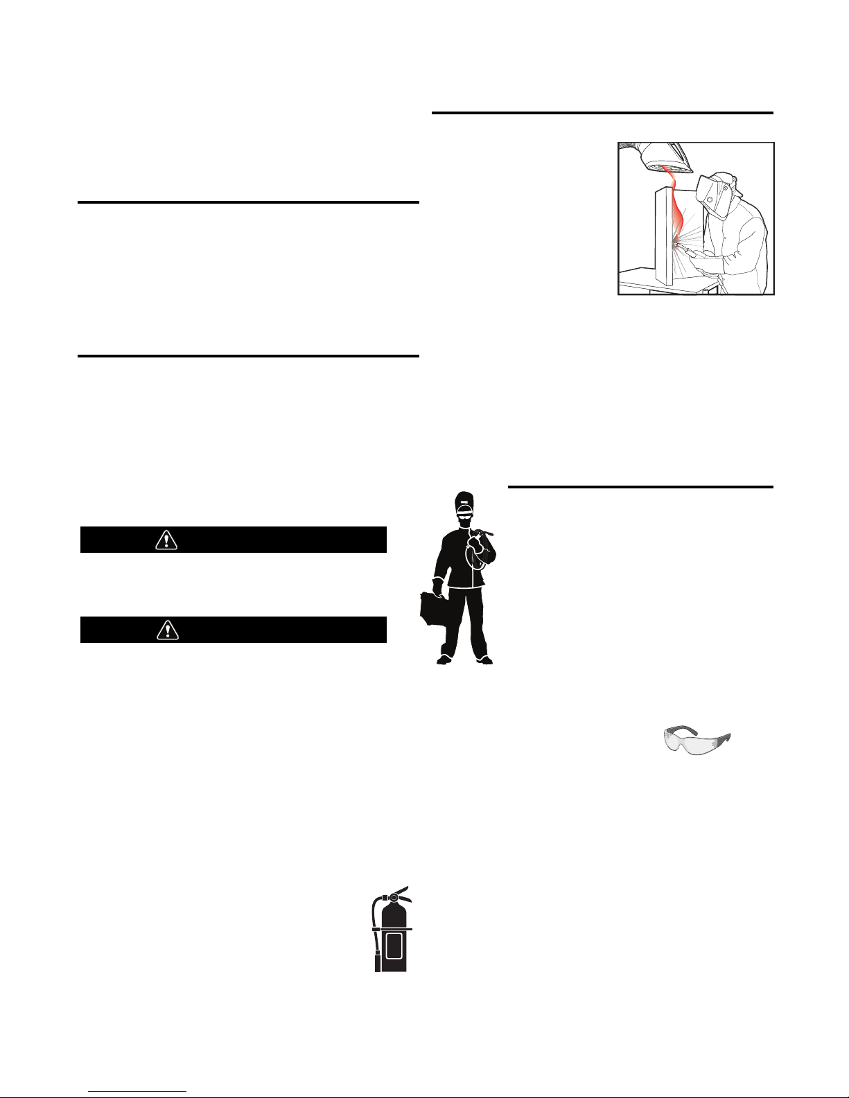
KEEP YOUR HEAD OUT OF THE FUMES.
DON’T get too close to the arc.
se corrective lenses if necessary
U
to stay a reasonable distance
away from the arc.
READ and obey the Safety Data
Sheet (SDS) and the warning label
that appears on all containers of
welding materials.
USE ENOUGH VENTILATION or
exhaust at the arc, or both, to
keep the fumes and gases from
your breathing zone and the general area.
IN A LARGE ROOM OR OUTDOORS, natural ventilation may be
adequate if you keep your head out of the fumes (See below).
USE NATURAL DRAFTS or fans to keep the fumes away
from your face.
If you de velop unusual symptoms, see your supervisor.
Perhaps the welding atmosphere and ventilation system
should be checked.
WEAR CORRECT EYE, EAR &
BODY PROTECTION
PROTECT your eyes and face with welding helmet
properly fitted and with proper grade of filter plate
(See ANSI Z49.1).
PROTECT your body from welding spatter and arc
flash with protective clothing including woolen
clothing, flame-proof apron and gloves, leather
leggings, and high boots.
PROTECT others from splatter, flash, and glare
with protective screens or barriers.
IN SOME AREAS, protection from noise may be appropriate.
BE SURE protective equipment is in good condition.
Also, wear safety glasses in work area
AT ALL TIMES.
SPECIAL SITUATIONS
DO NOT WELD OR CUT containers or materials which previously
had been in contact with hazardous substances unless they are
properly cleaned. This is extremely dangerous.
DO NOT WELD OR CUT painted or plated parts unless special
precautions with ventilation have been taken. They can release
highly toxic fumes or gases.
Additional precautionary measures
PROTECT compressed gas cylinders from excessive heat,
mechanical shocks, and arcs; fasten cylinders so they cannot fall.
BE SURE cylinders are never grounded or part of an
electrical circuit.
REMOVE all potential fire hazards from welding area.
ALWAYS HAVE FIRE FIGHTING EQUIPMENT READY FOR
IMMEDIATE USE AND KNOW HOW TO USE IT.
Safety 01 of 04 - 06/15/2016
SECTION A:
WARNINGS
CALIFORNIA PROPOSITION 65 WARNINGS
Diesel Engines
Diesel engine exhaust and some of its constituents are known
to the State of California to cause cancer, birth defects, and other
reproductive harm.
Gasoline Engines
The engine exhaust from this product contains chemicals known
to the State of California to cause cancer, birth defects, or other
reproductive harm.
ARC WELDING CAN BE HAZARDOUS. PROTECT
YOURSELF AND OTHERS FROM POSSIBLE SERIOUS
INJURY OR DEATH. KEEP CHILDREN AWAY.
PACEMAKER WEARERS SHOULD CONSULT WITH
THEIR DOCTOR BEFORE OPERATING.
Read and understand the following safety highlights. For
additional safety information, it is strongly recommended
that you purchase a copy of “Safety in Welding & Cutting ANSI Standard Z49.1” from the American Welding Society,
P.O. Box 351040, Miami, Florida 33135 or CSA Standard
W117.2-1974. A Free copy of “Arc Welding Safety” booklet
E205 is available from the Lincoln Electric Company,
22801 St. Clair Avenue, Cleveland, Ohio 44117-1199.
BE SURE THAT ALL INSTALLATION, OPERATION,
MAINTENANCE AND REPAIR PROCEDURES ARE
PERFORMED ONLY BY QUALIFIED INDIVIDUALS.
SAFETY
1.d. Keep all equipment safety guards, covers
and devices in position and in good repair.
Keep hands, hair, clothing and tools away
from V-belts, gears, fans and all other
moving parts when starting, operating or
repairing equipment.
1.e. In some cases it may be necessary to remove safety guards to
perform required maintenance. Remove guards only when
necessary and replace them when the maintenance requiring
heir removal is complete. Always use the greatest care when
t
working near moving parts.
1.f. Do not put your hands near the engine fan. Do not attempt to
override the governor or idler by pushing on the throttle control
rods while the engine is running.
1.g. To prevent accidentally starting gasoline engines while turning
the engine or welding generator during maintenance work,
disconnect the spark plug wires, distributor cap or magneto wire
as appropriate.
1.h. To avoid scalding, do not remove the radiator
pressure cap when the engine is
hot.
ELECTRIC AND
MAGNETIC FIELDS MAY
BE DANGEROUS
2.a. Electric current flowing through any conductor
causes localized Electric and Magnetic Fields (EMF).
Welding current creates EMF fields around welding cables
and welding machines
FOR ENGINE POWERED
EQUIPMENT.
1.a. Turn the engine off before troubleshooting
and maintenance work unless the
maintenance work requires it to be running.
1.b. Operate engines in open, well-ventilated
areas or vent the engine exhaust fumes outdoors.
1.c. Do not add the fuel near an open flame
welding arc or when the engine is running.
Stop the engine and allow it to cool before
refueling to prevent spilled fuel from
vaporizing on contact with hot engine parts
and igniting. Do not spill fuel when filling
tank. If fuel is spilled, wipe it up and do not start engine until
fumes have been eliminated.
2.b. EMF fields may interfere with some pacemakers, and
welders having a pacemaker should consult their physician
before welding.
2.c. Exposure to EMF fields in welding may have other health effects
which are now not known.
2.d. All welders should use the following procedures in order to
minimize exposure to EMF fields from the welding circuit:
2.d.1. Route the electrode and work cables together - Secure
them with tape when possible.
2.d.2. Never coil the electrode lead around your body.
2.d.3. Do not place your body between the electrode and work
cables. If the electrode cable is on your right side, the
work cable should also be on your right side.
2.d.4. Connect the work cable to the workpiece as close as possible to the area being welded.
2.d.5. Do not work next to welding power source.
Safety 02 of 04 - 06/15/2016
SAFETY
ELECTRIC SHOCK
CAN KILL.
3.a. The electrode and work (or ground) circuits are
electrically “hot” when the welder is on. Do
not touch these “hot” parts with your bare skin or wet clothing.
Wear dry, hole-free gloves to insulate hands.
3.b. Insulate yourself from work and ground using dry insulation.
Make certain the insulation is large enough to cover your full area
f physical contact with work and ground.
o
In addition to the normal safety precautions, if
welding must be performed under electrically
hazardous conditions (in damp locations or while
wearing wet clothing; on metal structures such as
floors, gratings or scaffolds; when in cramped
positions such as sitting, kneeling or lying, if there
is a high risk of unavoidable or accidental contact
with the workpiece or ground) use the following
equipment:
• Semiautomatic DC Constant Voltage (Wire) Welder.
• DC Manual (Stick) Welder.
• AC Welder with Reduced Voltage Control.
3.c. In semiautomatic or automatic wire welding, the electrode,
electrode reel, welding head, nozzle or semiautomatic welding
gun are also electrically “hot”.
3.d. Always be sure the work cable makes a good electrical
connection with the metal being welded. The connection should
be as close as possible to the area being welded.
3.e. Ground the work or metal to be welded to a good electrical (earth)
ground.
3.f. Maintain the electrode holder, work clamp, welding cable and
welding machine in good, safe operating condition. Replace
damaged insulation.
3.g. Never dip the electrode in water for cooling.
3.h. Never simultaneously touch electrically “hot” parts of electrode
holders connected to two welders because voltage
two can be the total of the open circuit voltage of both
welders.
3.i. When working above floor level, use a safety belt to protect
yourself from a fall should you get a shock.
between the
ARC RAYS CAN BURN.
4.a. Use a shield with the proper filter and cover plates to protect your
eyes from sparks and the rays of the arc when welding or
observing open arc welding. Headshield and filter lens should
conform to ANSI Z87. I standards.
4.b. Use suitable clothing made from durable flame-resistant material
to protect your skin and that of your helpers from the arc rays.
4.c. Protect other nearby personnel with suitable, non-flammable
screening and/or warn them not to watch the arc nor expose
themselves to the arc rays or to hot spatter or metal.
FUMES AND GASES
CAN BE DANGEROUS.
5.a. Welding may produce fumes and gases
hazardous to health. Avoid breathing these fumes and gases.
When welding, keep your head out of the fume. Use enough
ventilation and/or exhaust at the arc to keep fumes and gases
away from the breathing zone. When welding hardfacing
(see instructions on container or SDS) or on lead
or cadmium plated steel and other metals or
coatings which produce highly toxic fumes, keep
exposure as low as possible and within applicable
OSHA PEL and ACGIH TLV limits using local
exhaust or mechanical ventilation unless exposure
assessments indicate otherwise. In confined
spaces or in some circumstances, outdoors, a
respirator may also be required. Additional
precautions are also required when welding
on galvanized steel.
5. b. The operation of welding fume control equipment is affected by
various factors including proper use and positioning of the
equipment, maintenance of the equipment and the specific
welding procedure and application involved. Worker exposure
level should be checked upon installation and periodically
thereafter to be certain it is within applicable OSHA PEL and
ACGIH TLV limits.
5.c. Do not weld in locations near chlorinated hydrocarbon vapors
coming from degreasing, cleaning or spraying operations. The
heat and rays of the arc can react with solvent vapors to form
phosgene, a highly toxic gas, and other irritating products.
3.j. Also see It ems 6.c. and 8.
5.d. Shielding gases used for arc welding can displace air and
cause
injury or death. Always use enough ventilation, especially in
confined areas, to insure breathing air is safe.
5.e. Read and understand the manufacturer’s instructions for this
equipment and the consumables to be used, including the
Safety Data Sheet (SDS) and follow your employer’s safety
practices. SDS forms are available from your welding
distributor or from the manufacturer.
5.f. Also see item 1.b.
Safety 03 of 04 - 06/15/2016
SAFETY
WELDING AND CUTTING
SPARKS CAN CAUSE
FIRE OR EXPLOSION.
6.a. Remove fire hazards from the welding area. If
this is not possible, cover them to prevent the welding sparks
rom starting a fire. Remember that welding sparks and hot
f
materials from welding can easily go through small cracks and
openings to adjacent areas. Avoid welding near hydraulic lines.
Have a fire extinguisher readily available.
6.b. Where compressed gases are to be used at the job site, special
precautions should be used to prevent hazardous situations.
Refer to “Safety in Welding and Cutting” (ANSI Standard Z49.1)
and the operating information for the equipment being used.
6.c. When not welding, make certain no part of the electrode circuit is
touching the work or ground. Accidental contact can cause
overheating and create a fire hazard.
6.d. Do not heat, cut or weld tanks, drums or containers until the
proper steps have been taken to insure that such procedures
will not cause flammable or toxic vapors from substances inside.
They can cause an explosion even though they have been
“cleaned”. For information, purchase “Recommended Safe
Practices for the Preparation for Welding and Cutting of
Containers and Piping That Have Held Hazardous Substances”,
AWS F4.1 from the American Welding Society
(see address above).
6.e. Vent hollow castings or containers before heating, cutting or
welding. They may explode.
6.f. Sparks and spatter are thrown from the welding arc. Wear oil free
protective garments such as leather gloves, heavy shirt, cuffless
trousers, high shoes and a cap over your hair. Wear ear plugs
when welding out of position or in confined places. Always wear
safety glasses with side shields when in a welding area.
6.g. Connect the work cable to the work as close to the welding area
as practical. Work cables connected to the building framework or
other locations away from the welding area increase the
possibility of the welding current passing through lifting chains,
crane cables or other alternate circuits. This can create fire
hazards or overheat lifting chains or cables until they fail.
6.h. Also see item 1.c.
CYLINDER MAY EXPLODE IF
DAMAGED.
7.a. Use only compressed gas cylinders containing
the correct shielding gas for the process used
and properly operating regulators designed for
the gas and pressure used. All hoses, fittings,
tc. should be suitable for the application and
e
maintained in good condition.
7.b. Always keep cylinders in an upright position securely chained to
an undercarriage or fixed support.
7.c. Cylinders should be located:
• Away from areas where they may be struck or subjected
to physical damage.
• A safe distance from arc welding or cutting operations
and any other source of heat, sparks, or flame.
7.d. Never allow the electrode, electrode holder or any other
electrically “hot” parts to touch a cylinder.
7.e. Keep your head and face away from the cylinder valve outlet
when opening the cylinder valve.
7.f. Valve protection caps should always be in place and hand tight
except when the cylinder is in use or connected for use.
7.g. Read and follow the instructions on compressed gas cylinders,
associated equipment, and CGA publication P-l, “Precautions for
Safe Handling of Compressed Gases in Cylinders,” available from
the Compressed Gas Association, 14501 George Carter Way
Chantilly, VA 20151.
FOR ELECTRICALLY
POWERED EQUIPMENT.
8.a. Turn off input power using the disconnect
switch at the fuse box before working on
the equipment.
8.b. Install equipment in accordance with the U.S. National Electrical
Code, all local codes and the manufacturer’s recommendations.
6.I. Read and follow NFPA 51B “Standard for Fire Prevention During
Welding, Cutting and Other Hot Work”, available from NFPA, 1
Batterymarch Park, PO box 9101, Quincy, MA 022690-9101.
6.j. Do not use a welding power source for pipe thawing.
8.c. Ground the equipment in accordance with the U.S. National
Electrical Code and the manufacturer’s recommendations.
Refer to
http://www.lincolnelectric.com/safety
for additional safety information.
Safety 04 of 04 - 06/15/2016

vi
TABLE OF CONTENTS
Page
Installation.......................................................................................................................Section A
Technical Specifications.......................................................................................................A-1
Safety Precautions ........................................................................................................A-2
Location and Ventilation................................................................................................A-2
Stacking ........................................................................................................................A-2
Angle of Operation ........................................................................................................A-2
Lifting.............................................................................................................................A-2
High Altitude Operation .................................................................................................A-3
Welder Output Ratings at Temperatires above 40Cº....................................................A-3
Cold Weather Starting...................................................................................................A-3
Towing...........................................................................................................................A-3
Vehicle Mounting...........................................................................................................A-3
Pre-Operation Engine Service..............................................................................................A-3
Oil..................................................................................................................................A-4
Fuel ...............................................................................................................................A-4
Engine Coolant..............................................................................................................A-4
Battery Connections......................................................................................................A-4
Muffler Outlet Pipe ........................................................................................................A-4
Spark Arrester ...............................................................................................................A-4
Remote Control .............................................................................................................A-4
Electrical Connections..........................................................................................................A-5
Machine Grounding.......................................................................................................A-5
Welding Terminals ........................................................................................................A-5
Welding Output Cables .................................................................................................A-5
Cable Installation...........................................................................................................A-5
Auxiliary Power Receptacles and Plugs...............................................................................A-6
Residual Current Device Ready ...........................................................................................A-6
Standby Power Connections ................................................................................................A-6
Connection of Lincoln Electric Wire Feeders .......................................................................A-7
________________________________________________________________________________
vi
Operation.........................................................................................................................Section B
Safety Precautions ..............................................................................................................B-1
General Description..............................................................................................................B-1
For Auxiliary Power ..............................................................................................................B-1
Engine Operation..................................................................................................................B-1
Add Fuel ...............................................................................................................................B-1
Break in Period.....................................................................................................................B-1
Welder Controls .............................................................................................................B-2,B-3
Engine Controls .............................................................................................................B-3,B-4
Fuel Consumption .........................................................................................................B-3
Starting and Stopping the Engine .................................................................................B-4
Welding Operation................................................................................................................B-4
Duty Cycle and Electrode Information...........................................................................B-4
Constant Current (Stick) Welding..................................................................................B-4
Downhill Pipe (Stick) Welding .......................................................................................B-5
Wire Welding-CV...........................................................................................................B-5
Arc Gouging ..................................................................................................................B-5
Tig Welding ...................................................................................................................B-6
Typical Current Ranges for Tungsten Electrodes .........................................................B-6
Auxiliary Power.....................................................................................................................B-7
Simultaneous Welding and Power Loads .....................................................................B-7
Extension Cord Recommendations...............................................................................B-7
________________________________________________________________________________
Accessories .....................................................................................................Section C
Field Installed Options / Accessories ...............................................................................C-1
________________________________________________________________________________

vii
TABLE OF CONTENTS
Maintenance......................................................................................................Section D
Safety Precautions ................................................................................................D-1
outine Maintenance ............................................................................................D-1
R
Engine Service Items.............................................................................................D-1
Engine Oil Change..........................................................................................D-2
Engine Oil Filter Change.................................................................................D-2
Air Cleaner .....................................................................................................D-2
Service Instructions And Installation Tips for Engine Air Filter .......................D-3
Cooling System .....................................................................................................D-4
Fan Belt...........................................................................................................D-4
Fuel .................................................................................................................D-4
Bleeding the Fuel System ...............................................................................D-4
Fuel Filter ........................................................................................................D-5
Engine Adjustment ..........................................................................................D-5
Battery Maintenance .......................................................................................D-5
Servicing Optional Spark Arrestor ...................................................................D-5
Welder / Generator Maintenance ........................................................................D-6
Storage ...........................................................................................................D-6
Cleaning..........................................................................................................D-6
Brush Removal and Replacement ..................................................................D-6
GFCI Testing and Resetting Procedure..........................................................D-6
________________________________________________________________________
Troubleshooting ..............................................................................................Section E
How to Use Troubleshooting Guide.......................................................................E-1
Troubleshooting Guide ............................................................................E-2 thru E-6
________________________________________________________________________
Diagrams ..........................................................................................................Section F
Instructions for Installing a Residual Current Device......................................F-1, F-2
Connection Diagram with Optional Remote Control ..............................................F-3
Wiring Diagrams.............................................................................................F-4, F-5
Dimension Print......................................................................................................F-6
________________________________________________________________________
Parts List...................................................................................................P-608 SERIES
________________________________________________________________________
vii
A-1
INSTALLATION
TECHNICAL SPECIFICATIONS - VANTAGE®500-I (K2805-1)
INPUT - DIESEL ENGINE
Make/Model Description Speed (RPM) Displacement Starting Capacities
PERKINS cu. in. (ltrs.) System
4 cylinder 135.6(2.2)
32.7 HP High Idle 1880 starter (75.7 L)
(K2805-1) 1800 RPM
404D-22 naturally aspirated Full Load 1800 cold crank amps)
water cooled
Diesel Engine Low Idle 1400 (87.1 x 92.5mm) W/Built in Regulator 8.0 Qts. (7.6L)
Bore x Stroke inch (mm)
3.43 X 3.64
RATED OUTPUT @ 104° F (40° C) - WELDER
Welding Process
DC Constant Current
DC Pipe Current
Touch-Start™TIG
DC Constant Voltage
Arc Gouging
Welding Output
Current/Voltage/Duty Cycle
400A / 36V / 100%
450A / 34V / 60%
500A / 30V /40%
300A / 32V / 100%
250A / 30V / 100%
400A / 36V / 100%
450A / 34V / 60%
500A / 30V / 40%
400A / 36V / 100%
Output Range
30 TO 500 AMPS
40 TO 300 AMPS
20 TO 250 AMPS
14 TO 36 VOLTS
90 to 450 Amps
12VDC Battery &
(Group 34; 650
65 Amp Alternator Radiator Coolant:
Fuel: 20 gal.
Oil: 8.45Qts. (8L)
Max. Weld OCV
@Rated Load RPM
60 Volts
A-1
RATED OUTPUT @ 104° F (40° C).- GENERATOR
Auxiliary Power
19,000 Watts Peak, / 17,000 Watts Continuous, 60 Hz, 240 Volts 3-Phase
3600 Watts Peak
2400 Watts Peak
1800 Watts Peak
(2)
, / 3600 Watts Continuous, 60 Hz, 240 Volts 1-Phase
(2)
, / 2400 Watts Continuous, 60 Hz, 120 Volts 1-Phase
(2)
, / 1800 Watts Continuous, 60 Hz, 120 Volts 1-Phase
(1)
PHYSICAL DIMENSIONS
HEIGHT WIDTH DEPTH WEIGHT
35.94* in. 25.30 in 60.00 in.
913 mm 643 mm 1524 mm
1230 lbs. (559kg.)
ENGINE
LUBRICATION EMISSIONS FUEL SYSTEM GOVERNOR
Full Pressure EPA Tier 4 Mechanical Fuel Pump, Auto air bleed Mechanical
with Full Flow Filter Interim Compliant system, Electric shutoff solenoid, Indirect fuel injector.
AIR CLEANER ENGINE IDLER MUFFLER ENGINE PROTECTION
Low noise Muffler: Shutdown on low oil
Single Element Automatic Idler Top outlet can be rotated. pressure & high engine
Made from long life, aluminized steel. coolant temperature
ENGINE WARRANTY: 2 years / 2000 hours, all non-electric components, 3 years major non-electric components . See Perkins warranty for details.
MACHINE SPECIFICATIONS
RECEPTACLES AUXILIARY POWER CIRCUIT BREAKER OTHER CIRCUIT BREAKERS
1 - 120VAC Duplex NEMA (5-20R)-GFCI protected 1 - 20 amp for 120VAC Duplex (NEMA)
1 - 120VAC European (IEC 309)-GFCI protected 1 - 15 amp for 120VAC European (IEC 309)
1 - 240VAC European (IEC 309) 1 - 15 amp (2 -pole) for 240VAC European (IEC 309)
1 - 240VAC 3-Phase NEMA (15-50R) 1 - 50 amp (3-pole) for 240 VAC 3-Phase (NEMA)
(1)
Output rating in watts is equivalent to volt-amperes at unity power factor. Output voltage is within ± 10% at all loads up to
rated capacity. When welding, available auxiliary power will be reduced.
* To Top of enclosure, add 10.28”(261.1mm) to top of exhaust pipe. Add 3.43”(87.1mm) to top of Lift Bail.
(2)
Maximum per circuit breaker rating.
10AMP for Battery Charging Circuit
VANTAGE® 500-I

A-2
INSTALLATION
A-2
SAFETY PRECAUTIONS
WARNING
o not attempt to use this equipment until you
D
have thoroughly read the engine manufacturer’s
manual supplied with your welder. It includes
mportant safety precautions, detailed engine
i
starting, operating and maintenance instructions,
and parts lists.
------------------------------------------------------------------------
ELECTRIC SHOCK can kill.
• Do not touch electrically live parts or
electrode with skin or wet clothing.
• Ins u late yourse lf f r om w o rk a nd
ground
• Always wear dry insulating gloves.
------------------------------------------------------------------------
ENGINE EXHAUST can kill.
• Use in open, well ventilated areas or
vent exhaust outside.
------------------------------------------------------------------------
MOVING PARTS can injure.
• Do not operate with doors open or
guards off.
• Stop engine before servicing.
• Keep away from moving parts.
------------------------------------------------------------------------
See additional warning information at
front of this operator’s manual.
LIFTING
he VANTAGE® 500-I weighs approximately 1345lbs.
T
611kg.) with a full tank of fuel 1230lbs.(559kg) less
(
fuel. A lift bail is mounted to the machine and should
always be used when lifting the machine.
WARNING
• Lift only with equipment of adequate lifting capacity.
• Be sure machine is stable when lifting.
• Do not lift this machine using lift
bail if it is equipped with a heavy
accessory such as trailer or gas
cylinder.
FALLING • Do not lift machine if lift bail is
EQUIPMENT can damaged.
cause injury. • Do not operate machine while
suspended from lift bail.
------------------------------------------------------------------------
Only qualified personnel should install,
use, or service this equipment.
LOCATION AND VENTILATION
The welder should be located to provide an unrestricted flow of clean, cool air to the cooling air inlets and to
avoid restricting the cooling air outlets. Also, locate
the welder so that the engine exhaust fumes are properly vented to an outside area.
STACKING
VANTAGE® 500-I machines cannot be stacked.
ANGLE OF OPERATION
Engines are designed to run in the level condition
which is where the optimum performance is achieved.
The maximum angle of continuous operation is 25
degrees in all directions, 35 degrees Intermittent (less
than 10 minutes continuous) in all directions. If the
engine is to be operated at an angle, provisions must
be made for checking and maintaining the oil level at
the normal (FULL) oil capacity in the crankcase.
When operating the welder at an angle, the effective
fuel capacity will be slightly less than the amount
specified.
VANTAGE® 500-I

A-3
HIGH ALTITUDE OPERATION
At higher altitudes, output derating may be necessary. For maximum rating, derate the machine 2.5% to 3.5% for every 1000 ft.
(305m). Due to new EPA and other local emissions regulations,
odifications to the engine for high altitude are restricted within
m
the United States. For use above 6000 ft.(1828 m) an authorized Perkins engine field service shop should be contacted to
determine if any adjustments can be made for operation in higher elevations.
HIGH TEMPERATURE OPERATION
Tested for extreme temperature operation up to 55°C. Output
derated above 40°C.
INSTALLATION
Cold weather starting:
With a fully charged battery and the proper oil, the engine
should start satisfactorily down to -15°F(-26°C). If the engine
must be frequently started at or below 0°F (-18°C), it may be
desirable to install cold-starting aides. The use of No. 1D
diesel fuel is recommended in place of No. 2D at temperatures below 23°F (-5°C). Allow the engine to warm up before
applying a load or switching to high idle.
A-3
VEHICLE MOUNTING
WARNING
Improperly mounted concentrated loads may
cause unstable vehicle handling and tires or other
components to fail.
• Only transport this Equipment on serviceable
vehicles which are rated and designed for such
loads.
• Distribute, balance and secure loads so vehicle
is stable under conditions of use.
• Do not exceed maximum rated loads for components such as suspension, axles and tires.
• Mount equipment base to metal bed or frame of
vehicle.
• Follow vehicle manufacturer’s instructions.
------------------------------------------------------------------------
PRE-OPERATION ENGINE SERVICE
READ the engine operating and maintenance instructions supplied with this machine.
Note: Extreme cold weather starting may require
longer glow plug operation.
Under no conditions should ether or other starting
fluids be used with this engine!
------------------------------------------------------------------------
TOWING
WARNING
Use a recommended trailer for use with this equipment for road,
in-plant and yard towing by a vehicle(1). If the user adapts a
non-Lincoln trailer, he must assume responsibility that the
method of attachment and usage does not result in a safety
hazard or damage the welding equipment. Some of the factors
to be considered are as follows:
1. Design capacity of trailer vs. weight of Lincoln equipment and
likely additional attachments.
2. Proper support of, and attachment to, the base of the welding
equipment so there will be no undue stress to the framework.
3. Proper placement of the equipment on the trailer to insure
stability side to side and front to back when being moved and
when standing by itself while being operated or serviced.
4. Typical conditions of use, i.e., travel speed; roughness of surface on which the trailer will be operated; environmental conditions; like maintenance.
5. Conformance with federal, state and local laws.
(1) Consult applicable federal, state and local laws regarding specific requirements for use on public high-
ways.
(1)
WARNING
• Stop engine and allow to cool before fueling
• Do not smoke when fueling.
• Fill fuel tank at a moderate rate and do not overfill.
• Wipe up spilled fuel and allow fumes to clear
before starting engine.
• Keep sparks and flame away from tank.
------------------------------------------------------------------------
NOTE: This machine is furnished with a wet charged battery; if unused for several months, the battery may require a
booster charge. Be careful to charge the battery with the
correct polarity. (See Battery in “Maintenance Section”)
VANTAGE® 500-I
A-4
Because this portable engine driven welder creates its
own power, it is not necessary to connect its
rame to an earth ground, unless the machine
f
is connected to premises wiring (home, shop, etc.)
To prevent dangerous electric shock, other equipment
to which this engine driven welder supplies power
must:
Be grounded to the frame of the welder using a
•
grounded type plug or be double insulated.
• Do not ground the machine to a pipe that carries
explosive or combustible material.
INSTALLATION
WARNING
------------------------------------------------------------------------
When this welder is mounted on a truck or trailer, its
frame must be electrically bonded to the metal frame
of the vehicle. Use a #8 or larger copper wire connected between the machine grounding stud and the
frame of the vehicle. When this engine driven welder
is connected to premises wiring such as that in a
home or shop, its frame must be connected to the
system earth ground. See further connection instructions in the section entitle d "Stand b y Power
Connections" as well as the article on grounding in the
latest National Electrical Code and the local code.
In general, if the machine is to be grounded, it should
be connected with a #8 or larger copper wire to a solid
earth ground such as a metal water pipe going into
the ground for at least ten feet and having no insulated joints, or to the metal framework of a building
which has been effectively grounded.
The National Electrical Code lists a number of alternate means of grounding electrical equipment. A
machine grounding stud marked with the symbol
is provided on the front of the welder.
WELDING TERMINALS
The VANTAGE® 500-I is equipped with a toggle
switch for selecting "hot" welding terminal when in
the "WELD TERMINALS ON" position or "cold" welding terminal when i n the "REMOTELY CONTROLLED" position.
A-4
nections should be checked periodically and tightened
with a 3/4" wrench.
Table A.1 lists recommended cable sizes and lengths
for rated current and duty cycle. Length refers to the
istance from the welder to the work and back to the
d
welder. Cable diameters are increased for long cable
lengths to reduce voltage drops.
TABLE A.1
CABLE INSTALLATION
Install the welding cables to your VANTAGE® 500-I as
follows.
TOTAL COMBINED LENGTH OF
ELECTRODE AND WORK CABLES
Cable Length
0-100 Ft. (0-30 meters)
100-150 Ft. (30-46 meters)
150-200 Ft. (46-61 meters)
1. The engine must be OFF to install welding cables.
2. Remove the flanged nuts from the output terminals
3. Connect the electrode holder and work cables to
the weld output terminals. The terminals are identified on the case front.
4. Tighten the flanged nuts securely.
5. Be certain that the metal piece you are welding (the
“work”) is properly connected to the work clamp and
cable.
6. Check and tighten the connections periodically.
• Loose connections will cause the output termi-
nals to overheat. The terminals may eventually
melt.
• Do not cross the welding cables at the output ter-
minal connection. Keep the cables isolated and
Cable Size for
400 Amps
60% Duty Cycle
2 / 0 AWG
2 / 0 AWG
3 / 0 AWG
CAUTION
separate from one another.
------------------------------------------------------------------------
WELDING OUTPUT CABLES
With the engine off connect the electrode and work
cables to the output studs. The welding process dictates the polarity of the electrode cable. These con-
AUXILIARY POWER RECEPTACLES
Start the engine and set the “IDLER” control switch to
the “High Idle” mode. Voltage is now correct at the
receptacles for auxiliary power. This must be done
VANTAGE® 500-I

A-5
efore a tripped GFCI can be reset properly. See the
b
MAINTENANCE section for more detailed information
n testing and resetting the GFCI.
o
The auxiliary power of the VANTAGE® 500-I consists
of Single Phase and Three Phase 60Hz Power. Out put
Voltage is within +/- 10% at loads up to rated capacity.
Single Phase:
One 120VAC NEMA (5-20R) 20 amp duplex receptacle
is protected by a 20 amp circuit breaker that provides
2400 watts Peak / 2400 watts Continuous power.
Maximum current is 20 amps total.
One 120VAC (IEC 309) 16 amp receptacle is protected
by a 15 amp circuit breaker that provides 1800 watts
Peak / 1800 watts Continuous power. Maximum current
is 15 amps.
One 240VAC (IEC 309) 16 amp receptacle is protected
by a 15 amp 2-pole circuit breaker that provides 3600
watts Peak / 3600 watts Continuous power. The 2-pole
circuit breaker disconnects both hot leads at the same
time. Maximum current is 15 amps.
Three-Phases:
One 240VAC NEMA (15-50R) 50 amp receptacle is
protected by a 50 amp 3-pole circuit breaker that provides 19,000 watts Peak / 17,000 watts Continuous
power. The 3-pole circuit breaker disconnects all 3
Phases at the same time. Maximum current is 41
amps.
INSTALLATION
A-5
hole sized and shaped to accept a typical 2-pole
(RCD). A coverplate with a label “RCD READY” covers the hole and secures a mounting bracket on the
ackside of the panel. See Section F Diagrams of this
b
Operator’s Manual for instructions on installing an
(RCD).
Note: The (RCD) should be rated for 15 amps.
STANDBY POWER CONNECTIONS
The VANTAGE® 500-I is suitable for temporary,
standby or emergency power using the engine manufacturer’s recommended maintenance schedule.
The VANTAGE® 500-I can be permanently installed
as a standby power unit for 240 VAC, 3 wire, single
phase, 50 amp service. Connections must be made
by a licensed electrician who can determine how the
120/240 VAC power can be adapted to the particular
installation and comply with all applicable electrical
codes.
Take necessary steps to assure load is limited to the
capacity of the VANTAGE® 500-I
• Only a licensed, certified, trained electrician
should install the machine to a premises or residential electrical system. Be certain that:
• The insta llation comp lies wi th the Nati onal
Electrical Code and all other applicable electrical
120 V RECEPTACLES
A GFCI protects, the two 120V Auxiliary Power receptacles. A GFCI (Ground Fault Circuit Interrupter) electrical receptacle is a device to protect against electric
shock should a piece of defective equipment connected
to it develop a ground fault. If this situation should
occur, the GFCI will trip, removing voltage from the output of the receptacle. If a GFCI is tripped see the
MAINTENANCE section for detailed information on
testing and resetting it. A GFCI should be properly tested at least once every month.
The 120 V auxiliary power receptacles should only be
used with three wire grounded type plugs or approved
double insulated tools with two wire plugs. The current
rating of any plug used with the system must be at
least equal to the current capacity of the associated
receptacle.
RESIDUAL CURRENT DEVICE READY
The Vantage 500-I is configured to allow for the addition of a Residual Current Device (RCD) to protect the
240V Single Phase Receptacle. The auxiliary power
area on the front panel of the Vantage 500-I has a
VANTAGE® 500-I
WARNING
codes.
• The premises is isolated and no feedback into
the utility system can occur. Certain state and
local laws require the premises to be isolated
before the generator is linked to the premises.
Check your state and local requirements.
------------------------------------------------------------------------

A-6
INSTALLATION
A-6
CONNECTION OF LINCOLN ELECTRIC
WIRE FEEDERS
WARNING
Shut off welder before making any electrical connections.
------------------------------------------------------------------------
Connection of LN-15 Across The-Arc Model to the
VANTAGE® 500-I
1. Shut the welder off.
2. For electrode Positive, connect the electrode
cable to the "+" terminal of the welder and work
cable to the "-" terminal of the welder. For electrode Negative, connect the electrode cable to the
"-" terminal of the welder and work cable to the "+"
terminal of the welder.
3. Attach the single lead from the front of the LN-15
to work using the spring clip at the end of the lead.
This is a control lead to supply current to the wire
feeder motor; it does not carry welding current.
4. Set the MODE switch to the "CV-WIRE " position.
5. Set the "WELD TERMINALS" switch to "WELD
TERMINALS ON".
1. Shut the welder off.
2. For electrode Positive, connect the electrode
cable from the Wire Feeder to the "+" terminal of
the welder and work cable to the "-" terminal of the
welder. For electrode Negative, connect the electrode cable from the Wire Feeder to the "-" termi-
al of the welder and work cable to the "+" termi-
n
nal of the welder.
3. Attach the single lead from the front of the Wire
Feeder to work using the spring clip at the end of
the lead. This is a control lead to supply current to
the wire feeder motor; it does not carry welding
current.
4. Set the MODE switch to the "CV-WIRE " position.
5. Set the "WELD TERMINALS" switch to "WELD
TERMINALS ON"
6. Set the "ARC CONTROL" knob to "0" initially and
adjust to suit.
7. Set the "IDLE" switch to the "AUTO" position.
When not welding, the VANTAGE® 500-I engine
will be at the low idle speed. If you are using an
LN-25 with an internal contactor, the electrode is
not energized until the gun trigger is closed.
6. Set the "ARC CONTROL" knob to "0" initially and
adjust to suit.
7. Set the "IDLE" switch to the "AUTO" position.
8. When the gun trigger is closed, the current sensing circuit will cause the VANTAGE® 500-I engine
to go to the high idle speed, the wire will begin to
feed and the welding process started. When welding is stopped, the engine will revert to low idle
speed after approximately 12 seconds unless
welding is resumed.
NOTE: LN-15 Control Cable Model will not work with
the Vantage 500-I.
Connection of the LN-25 PRO or LN-25 to the VANTAGE® 500-I
The LN-25 PRO or LN-25 with or without an internal
contactor may be used with the VANTAGE® 500-I.
See the appropriate connection diagram in Section F.
NOTE: The LN-25 (K431) Remote Control Module
and (K432) Remote Cable are not recommended for
use with the VANTAGE® 500-I.
8. When the gun trigger is closed, the current sensing circuit will cause the VANTAGE® 500-I engine
to go to the high idle speed, the wire will begin to
feed and the welding process started. When welding is stopped, the engine will revert to low idle
speed after approximately 12 seconds unless
welding is resumed.
CAUTION
If you are using an LN-25 without an internal contactor, the electrode will be energized when the
VANTAGE® 500-I is started.
------------------------------------------------------------------------
VANTAGE® 500-I
B-1
OPERATION
SAFETY PRECAUTIONS
WARNING
Do not attempt to use this equipment until you
ave thoroughly read the engine manufacturer’s
h
manual supplied with your welder. It includes
important safety precautions, detailed engine
starting, operating and maintenance instructions,
and parts lists.
------------------------------------------------------------------------
ELECTRIC SHOCK can kill.
• Do not touch electrically live parts or
electrode with skin or wet clothing.
• Insu l ate y o urself from wo r k an d
ground
• Always wear dry insulating gloves.
• Always operate the welder with the hinged door
closed and the side panels in place.
• Re ad carefully th e S afety Precaut ions page
before operating this machine. Always follow
these and any other safety procedures included
in this manual and in the Engine Instruction
Manual.
------------------------------------------------------------------------
GENERAL DESCRIPTION
The VANTAGE® 500-I is a diesel engine powered DC
multi-process welding power source and 120 / 240
volt AC power generator. The engine drives a generator that supplies three phase power for the DC welding circuit, single phase and Three Phase power for
the AC auxiliary outlets. The DC welding control system uses state of the art Chopper Technology (CT™)
for superior welding performance.
FOR AUXILIARY POWER:
Start the engine and set the IDLER control switch to
the desired operating mode. Full power is available
regardless of the welding control settings providing no
welding current is being drawn.
B-1
WARNING
ADD FUEL
• Stop engine while fueling.
• Do not smoke when fueling.
• Keep sparks and flame away
rom tank.
f
• Do not leave unattended while
fueling.
DIESEL FUEL
can cause fire.
------------------------------------------------------------------------
• Remove the fuel tank cap.
• Fill the tank. DO NOT FILL THE TANK TO THE
POINT OF OVERFLOW.
• Replace the fuel cap and tighten securely.
• See Engine Owner’s Manual for specific fuel recommendations.
• Wipe up spilled fuel and allow
fumes to clear before starting
engine.
• Do not overfill tank, fuel expansion may cause overflow.
DIESEL FUEL ONLY
BREAK-IN PERIOD
The engine will use a small amount of oil during its
“break-in” period. The break-in period is about 50 running hours.
Ch eck th e o il ever y f our ho urs during break-in .
Change the oil after the first 50 hours of operation and
every 200 hours thereafter. Change the oil filter at
each oil change.
During break-in, subject the Welder to moderate
CAUTION
ENGINE OPERATION
Before Starting the Engine:
• Be sure the machine is on a level surface.
• Open side engine door and remove the
engine oil dipstick and wipe it with a clean
cloth. Reinsert the dipstick and check the level on
the dipstick.
• Add oil (if necessary) to bring the level up to the full
mark. Do not overfill. Close engine door.
• Check radiator for proper coolant level. (Fill if necessary).
• See Engine Owner’s Manual for specific oil and
coolant recommendations.
loads. Avoid long periods running at idle. Before
stopping the engine, remove all loads and allow
the engine to cool several minutes.
------------------------------------------------------------------------
VANTAGE® 500-I
B-2
10
OPERATION
IGURE B.1
F
B-2
1
2
8
3
4
11
9
14
19
13
17
5
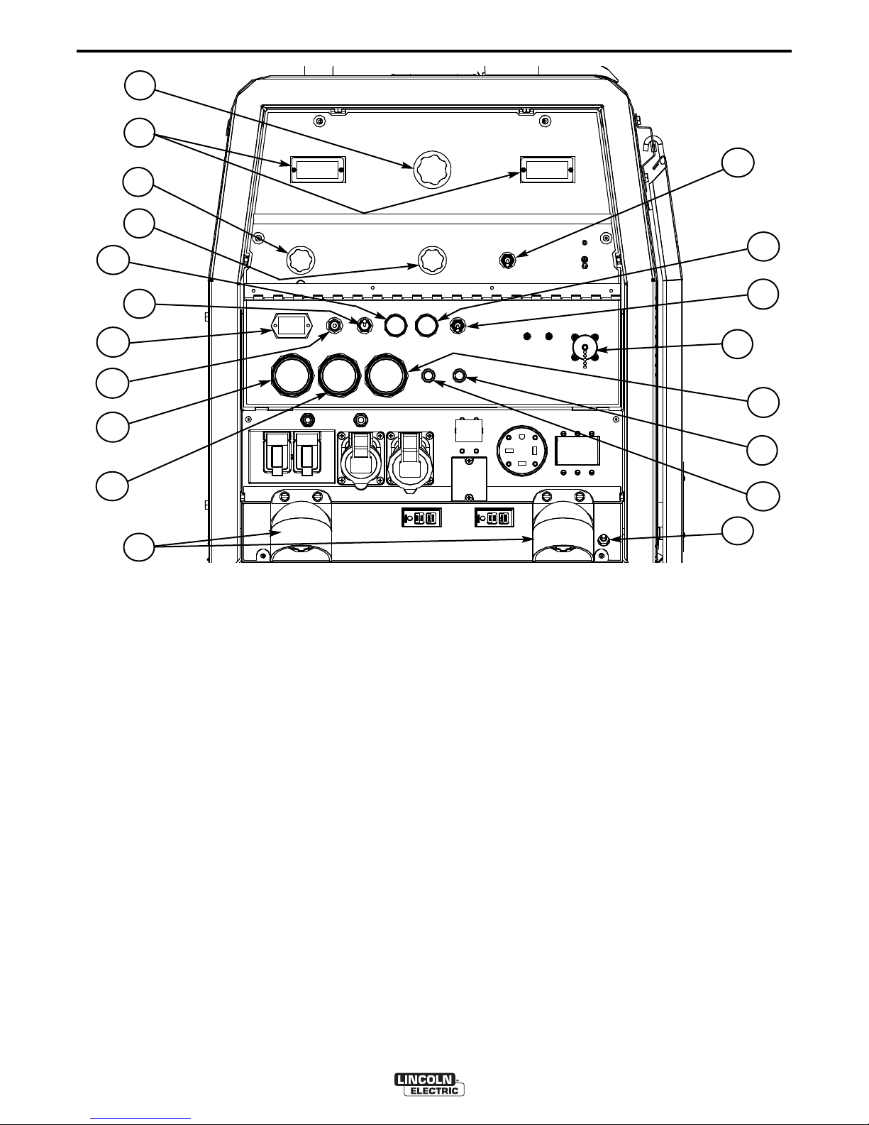
WELDING CONTROLS (Figure B.1)
1. OUTPUT CONTROL- The OUTPUT dial is used to
preset the output voltage or current as displayed on the
digital meters for the five welding modes. When in the
ARC GOUGING or CV-WIRE modes and when a remote
control is connected to the 6-Pin or 14-Pin Connector, the
auto-sensing circuit automatically switches the OUTPUT
CONTROL from control at the welder to the remote control. When in the CC-STICK or DOWNHILL PIPE mode
and when a remote control is connected to the 6-Pin or
14-Pin connector, the output control is used to set the
maximum current range of the remote.
EXAMPLE: When the OUTPUT CONTROL on the welder
is set to 200 amps the current range on the remote control
will be Min-200 amps, rather than the full Min-Max amps.
Any current range that is less than the full range provides
finer current resolution for more fine tuning of the output.
In the CV-WIRE mode, if the feeder being used has a voltage control when the wire feeder control cable is connected to the 14-Pin Connector, the auto-sensing circuit automatically makes OUTPUT CONTROL inactive and the
wire feeder voltage control active. Otherwise, the OUTPUT CONTROL is used to preset the voltage.
12
7
18
15
16
6
When in the TOUCH START TIG mode and when an
Amptrol is connected to the 6-Pin Connector, the OUTPUT dial is used to set the maximum current range of the
CURRENT CONTROL of the Amptrol.
2. DIGITAL OUTPUT METERS-The digital meters
allow the output voltage (CV-WIRE mode) or current
(CC-STICK, DOWN HILL PIPE and TIG modes) to be set
prior to welding using the OUTPUT control dial. During
welding, the meter display the actual output voltage
(VOLTS) and current (AMPS). A memory feature holds
the display of both meters on for seven seconds after
welding is stopped. This allows the operator to read the
actual current and voltage just prior to when welding was
ceased.
While the display is being held the left-most decimal
point in each display will be flashing. The accuracy of the
meters is +/- 3%.
3. WELD MODE SELECTOR SWITCH-
(Provides Five selectable welding modes)
CV-WIRE
ARC GOUGING
DOWNHILL PIPE
CC-STICK
TOUCH START TIG
VANTAGE® 500-I
B-3
OPERATION
B-3
4. ARC CONTROL- The ARC CONTROL dial is active
in the CV-WIRE , CC-S TICK and DO WNHILL PI PE
modes, and has different functions in these modes. This
ontro l is no t active in th e TIG mo de and ARC
c
GOUGING mode.
CC-STICK mode: In this mode, the ARC CONTROL dial
ets the short circuit current (arc-force) during stick weld-
s
ing to adjust for a soft or crisp arc. Increasing the dial
from –10 (soft) to +10 (crisp) increases the short circuit
current and prevents sticking of the electrode to the plate
while welding. This can also increase spatter. It is recommended that the ARC CONTROL be set to the minimum
number without electrode sticking. Start with a setting at
0.
DOWNHILL PIPE mode: In this mode, the ARC CONTROL dial sets the short circuit current (arc-force) during
stick welding to adjust for a soft or a more forceful digging
arc (crisp). Increasing the number from –10 (soft) to +10
(crisp) increases the short circuit current which results in a
more forceful digging arc. Typically a forceful digging arc
is preferred for root and hot passes. A softer arc is preferred for fill and cap passes where weld puddle control
and deposition ("stacking" of iron) are key to fast travel
speeds. It is recommended that the ARC CONTROL be
set initially at 0.
CV-WIRE mode: In this mode, turning the ARC CONTROL clock wise from –10 (soft) to +10 (crisp) changes
the arc from soft and washed-in to crisp and narrow. It
acts as an inductance/pinch control. The proper setting
depends on the procedure and operator preference. Start
with a setting of 0.
5. WELD OUTPUT TERMINALS WITH FLANGE
NUT-
Provides a connection point for the electrode and
work cables.
6. GROUND STUD- Provides a connection point for
connecting the machine case to earth ground.
7. 6-PIN CONNECTOR- For attaching optional remote
control equipment. Includes auto-sensing remote control
circuit.
8. WELD TERMINALS CONTROL SWITCH- In the
WELD TERMINALS ON position, the output is electrically
hot all the time. In the REMOTELY CONTROLLED position, the output is controlled by a wire feeder or amptrol
device, and is electrically off until a remote switch is
depressed.
ENGINE CONTROLS:
9. RUN/STOP SWITCH - RUN position energizes the
ngine prior to starting. STOP position stops the engine.
e
The oil pressure interlock switch prevents battery drain if
the switch is left in the RUN position and the engine is
not operating.
10. GLOW PLUG PUSH BUTTON -
• When pushed activates the glow plugs. Glow plug
should not be activated for more than 20 seconds continuously.
11. START PUSH BUTTON - Energizes the starter
motor to crank the engine.
12. IDLER SWITCH- Has two positions as follows:
1) In the HIGH position, the engine runs at the high
idle speed controlled by the engine governor.
2) In the AUTO position, the idler operates
as follows:
• When switched from HIGH to AUTO or after starting
the engine, the engine will operate at full speed for
approximately 12 seconds and then go to low idle
speed.
• When the electrode touches the work or power is
drawn for lights or tools (approximately 100 Watts minimum), the engine accelerates and operates at full
speed.
• When welding ceases or the AC power load is turned
off, a fixed time delay of approximately 12 seconds
starts. If the welding or AC power load is not restarted
before the end of the time delay, the idler reduces the
engine speed to low idle speed.
• The engine will automatically return to high idle speed
when there is welding load or AC power load reapplied.
13. ELECTRIC FUEL GAUGE- The elec tric fuel
gauge gives accurate and reliable indication as to how
much fuel is in the fuel tank.
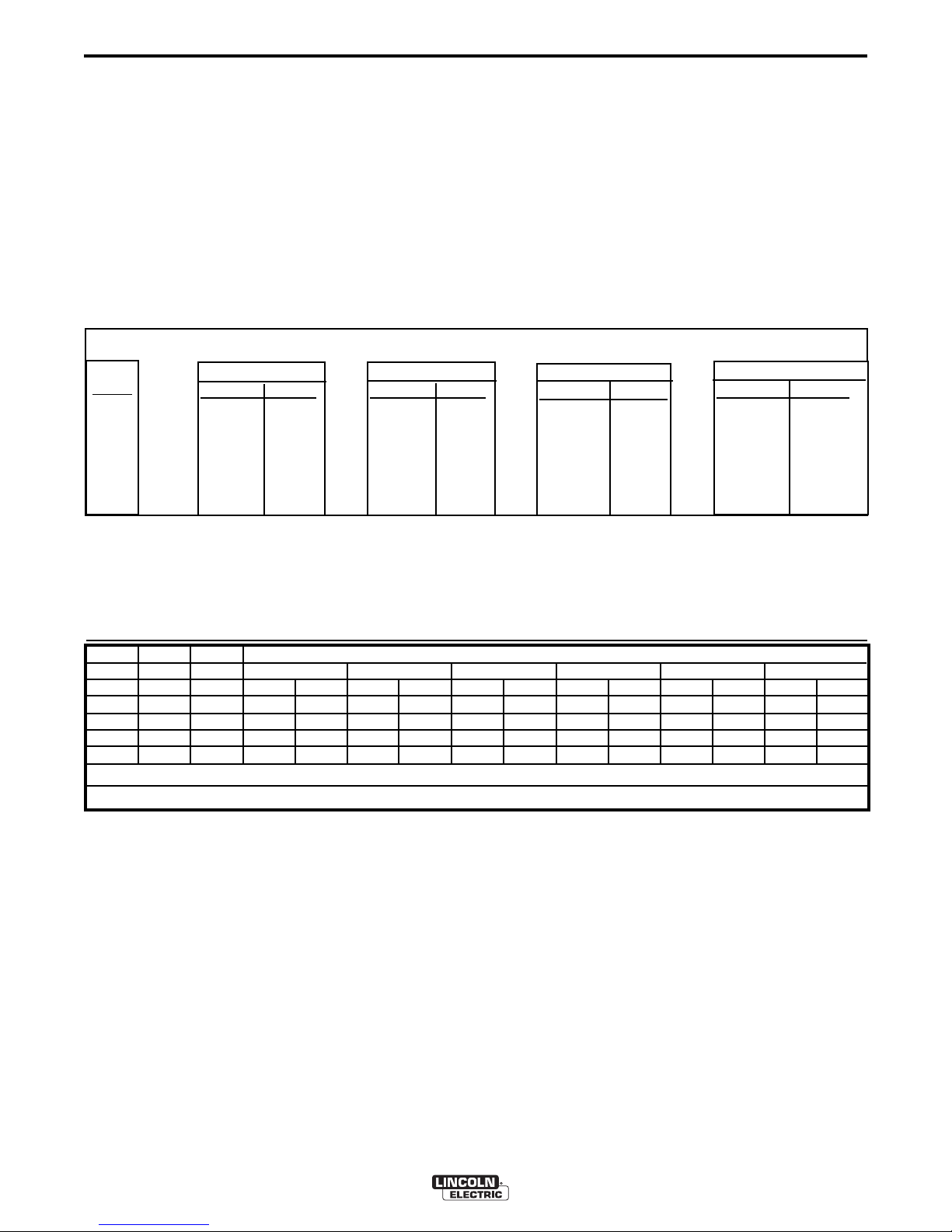
TABLE B.1
TYPICAL VANTAGE® 500-I FUEL CONSUMPTION
PERKINS 404D-22
Gal./Hr (Liters/Hr)
Low Idle - No Load
1400 R.P.M.
High Idle - No Load
1880 R.P.M.
DC Weld Output
400 Amps @ 36 Volts
17,000 Watts 3 Phase
NOTE: This data is for reference only. Fuel consumption is approximate and can be influenced by many
factors, including engine maintenance, environmental
conditions and fuel quality.
.26 (.97)
.42 (1.57)
1.18 (4.46)
1.24 (4.68)
Running Time for
20 gallons / hours
76.92
47.62
16.95
16.13
VANTAGE® 500-I

B-4
OPERATION
14. ENGINE HOUR METER- Displays the total time
that the engine has been running. This meter is useful
for scheduling prescribed maintenance.
B-4
NOTE: If the unit fails to start turn Run/Stop switch
to off and repeat step 3 through step 7 after
aiting 30 seconds.
w
15. ENGINE PROTECTION LIGHT- A warning indi-
ator light for Low Oil Pressure and/or Coolant Over
c
Temperature.The light is off when the systems are functioning properly. The light will come on and the engine
will shutdown when there is Low Oil Pressure and/or
the Coolant is Over Temperature.
Note: The light remains off when the RUN-STOP switch
is in the "ON" position prior to starting the engine.
However if the engine is not started within 60 seconds
the light will come on. When this happens the RUNSTOP switch must be returned to the "OFF" position to
reset the engine protection system and light.
16. BATTERY CHARGING LIGHT- A warning
indicator light for Low/No battery charge. The light is off
when the systems are functioning properly. The light
will come on if there is a Low/No battery condition but
the machine will continue to run.
Note:
The light may or may not come on when the RUNSTOP switch is in the "ON" position. It will come on during cranking and stay on until the engine starts. After
starting the engine the light will go off unless a Low/No
battery charge condition exists.
17. COOLANT TEMPERATURE GAUGE-A indica-
tor of engine coolant temperature.
18. OIL PRESSURE GAUGE- A indicator of engine
Oil Pressure.
19. CIRCUIT BREAKER- For protection of Battery
Charging Circuit.
CAUTION
• Do not allow the starter motor to run continuously
for more than 20 seconds.
Do not push the START button while the engine
•
is running because this can damage the ring
gear and/or the starter motor.
• IF the Engine Protection or Battery Charging
Lights do “not” turn off shortly after starting the
engine shut o ff th e engine immediately a nd
determine the cause.
------------------------------------------------------------------------
NOTE: When starting for the first time, or after and
extended period of time of not operating, it will take
longer than normal to start because the fuel pump
has to fill the fuel system. For best results, bleed the
fuel system as indicated in Maintenance Section of
this manual.
STOPPING THE ENGINE
Remove all welding and auxiliary power loads and
allow the engine to run at low idle speed for a few
minutes to cool the engine.
STOP the engine by placing the RUN-STOP switch in
the STOP position.
NOTE: A fuel shut off valve is located on the fuel pre-
filter.
WELDER OPERATION
DUTY CYCLE
Duty Cycle is the percentage of time the load is being
applied in a 10 minute period. For example a 60% duty
cycle, represents 6 minutes of load and 4 minutes of no
load in a 10 minute period.
ELECTRODE INFORMATION
STARTING THE ENGINE
1. Remove all plugs connected to the AC power receptacles.
2. Set IDLER switch to AUTO.
3. Press Glow Plug Button and hold 15 to 20 seconds.
4. Set the RUN/STOP switch to RUN.
5. Press START button until the engine starts or for up to
10 seconds. Continue to hold the glow plug button for up
to an additional 10 seconds.
6. Release the engine START button immediately when the
engine starts.
7. The engine will run at high idle speed for approximately
12 seconds and then drop to low idle speed. Allow the
engine to warm up at low idle for several minutes before
applying a load and/or switching to high idle. Allow a
longer warm up time in cold weather.
For any electrode the procedures should be kept within the rating of the machine. For information on electrodes and their proper application see (www.lincolnelectric.com) or the appropriate Lincoln publication.
The VANTAGE® 500-I can be used with a broad range
of DC stick electrodes. The MODE switch provides two
stick welding settings as follows:
CONSTANT CURRENT (CC-STICK) WELDING
The CC-STICK position of the MODE switch is designed
for horizontal and vertical-up welding with all types of
electrodes, especially low hydrogen. The OUTPUT CONTROL dial adjusts the full output range for stick welding.
The ARC CONTROL dial sets the short circuit current
VANTAGE® 500-I

B-5
(arc-force) during stick welding to adjust for a soft
or crisp arc. Increasing the number from -10(soft) to
10(crisp) increases the short circuit current and
+
prevents sticking of the electrode to the plate while
elding. This can also increase spatter. It is recom-
w
mended that the ARC CONTROL be set to the minimum number without electrode sticking. Start with
the dial set at 0.
OPERATION
DOWNHILL PIPE WELDING
B-5
ARC GOUGING
The VANTAGE® 500-I can be used for arc gouging.
or optimal performance, set the MODE switch to
F
ARC GOUGING.
Set the OUTPUT CONTROL knob to adjust output
urrent to the desired level for the gouging electrode
c
being used according to the ratings in the following
Table B.2.
This slope controlled setting is intended for "out-ofposition" and "down hill" pipe welding where the
operator would like to control the current level by
changing the arc length.
The OUTPUT CONTROL dial adjusts the full output
range for pipe welding.
The ARC CONTROL dial sets the short circuit current (arc-force) during stick welding to adjust for a
soft or more forceful digging arc (crisp). Increasing
the number from -10(soft) to +10(crisp) increases
the short circuit current which results in a more
forceful digging arc.
Typically a forceful digging arc is preferred for root
and hot passes. A softer arc is preferred for fill and
cap passes where weld puddle control and depositi on (“st acki ng” of iron) are key to fast travel
speeds. This can also increase spatter.
It is recommended that the ARC CONTROL be set
to the minimum number without electrode sticking.
Start with the dial set at 0.
TABLE B.2
Carbon Diameter Current Range (DC, elec-
trode positive)
1/8"(3.2mm) 60-90 Amps
5/32"(4.0mm) 90-150 Amps
3/16"9(4.8mm) 200-250 Amps
1/4"(6.4mm) 300-400 Amps
5/16"(8.0mm) 400-Max.Amps
The ARC CONTROL is not active in the ARC GOUGING Mode. The ARC CONTROL is automatically set
to maxim um when the ARC GOUGING mode is
selected which provides the best ARC GOUGING performance.
WIRE WELDING-CV
Connect a wire feeder to the VANTAGE® 500-I
according to the instructions in INSTALLATION
INSTRUCTIONS Section.
The VANTAGE® 500-I in the CV-WIRE mode, permits it to be used with a broad range of flux cored
wire (Innershield and Outershield) electrodes and
solid wires for MIG welding (gas metal arc welding).
Welding can be finely tuned using the ARC CONTROL. Turning the ARC CONTROL clockwise from
–10 (soft) to +10 (crisp) changes the arc from soft
and washed-in to crisp and narrow. It acts as an
ind u ctanc e /pinc h control . The p r oper set ting
depends on the procedure and operator preference. Start with the dial set at 0.
VANTAGE® 500-I
B-6
INSTALLATION
B-6
OIL
The VANTAGE® 500-I is shipped with the engine
crankcase filled with high quality SAE 10W-30 Oil that
meets classification CG-4 or CH-4 for diesel engines.
heck the oil level before starting the engine. If it is not
C
up to the full mark on the dip stick, add oil as required.
Check the oil level every four hours of running time during the first 50 running hours. Refer to the engine
Operator’s Manual for specific oil recommendations and
break-in information. The oil change interval is dependent on the quality of the oil and the operating environment. Refer to the Engine Operator’s Manual for more
details on the proper service and maintenance intervals.
FUEL
USE DIESEL FUEL ONLY
WARNING
• Fill the fuel tank with clean, fresh fuel. The
capacity of the tank is 20 gals. (75.7 ltrs). When
the fuel gauge reads empty the tank contains
approximately 2 gals. (7.6ltrs.) of reserve fuel.
NOTE: A fuel shut off valve is located on the pre-
filter/sediment filter. Which should be in
the closed position when the welder is not
used for extended periods of time.
------------------------------------------------------------------------
ENGINE COOLING SYSTEM
WARNING
Air to cool the engine is drawn in the side and
exhausted through radiator & case back. It is
important that the intake and exhaust air is not
restricted. Allow a minimum clearance of 1ft .
(0.6m) from the case back and 16in.(406mm) from
either side of the base to a vertical surface.
------------------------------------------------------------------------
BATTERY CONNECTION
CAUTION
MUFFLER OUTLET PIPE
Using the clamp provided secure the outlet pipe to the outlet
ube with the pipe positioned such that it will direct the
t
exhaust in the desired direction. Tighten using a 9/16" socket or wrench.
SPARK ARRESTER
ome federal, state or local laws may require that gasoline
S
or diesel engines be equipped with exhaust spark arresters
when they are operated in certain locations where unarrested sparks may present a fire hazard. The standard muffler
included with t his welder does not qualify as a spark
arrester. When required by local regulations, a suitable
spark arrester, such as the K903-1 must be installed and
properly maintained.
An incorrect spark arrestor may lead to damage to the
engine or adversely affect performance.
------------------------------------------------------------------------
REMOTE CONTROL
WARNING
The VANTAGE® 500-I is equipped with a 6-pin connector.
When in the ARC GOUGING or CV-WIRE modes and when a
remote control is connected to the 6-pin Connector, the autosensing circuit automatically switches the OUTPUT control from
control at the welder to remote control.
When in TOUCH START TIG mode and when a Amptrol is connected to the 6-Pin Connector, the OUTPUT dial is used to set
the maximum current range of the CURRENT CONTROL of the
Amptrol.
When in the CC-STICK or DOWNHILL PIPE mode and when a
remote control is connected to the 6-Pin connector, the output
control is used to set the maximum current range of the remote.
EXAMPLE: When the OUTPUT CONTROL on the welder is set
to 200 amps the current range on the remote control will be
Min-200 amps, rather than the full Min-Max amps. Any current
range that is less than the full range provides finer current resolution for more fine tuning of the output.
Use caution as the electrolyte is a strong acid that
can burn skin and damage eyes.
------------------------------------------------------------------------
The VANTAGE® 500-I is shipped with the negative
battery cable disconnected. Make certain that the
RUN-STOP switch is in the STOP position. Remove
the two screws from the battery tray using a screwdriver or a 3/8" socket. Attach the negative battery
cable to the negative battery terminal and tighten
using a 1/2" socket or wrench.
ELECTRICAL CONNECTIONS
MACHINE GROUNDING
VANTAGE® 500-I

B-7
OPERATION
B-7
TIG WELDING
The TOUCH START TIG setting of the MODE switch
is for DC TIG (Tungsten Inert Gas) welding. To initiate
a weld, the OUTPUT CONTROL dial is first set to the
desired current and the tungsten is touched to the
work. During the time the tungsten is touching the
work there is very little voltage or current and, in general, no tungsten contamination. Then, the tungsten is
gently lifted off the work in a rocking motion, which
establishes the arc.
When in the TOUCH START TIG mode and when a
Amptrol is connected to the 6-Pin connector the OUTPUT CONTROL dial is used to set the maximum current range of the current control of the Amptrol.
The ARC CONTROL is not active in the TIG mode. To
STOP a weld, simply pull the TIG torch away from the
work.
When the arc voltage reaches approximately 30 Volts
the arc will go out and the machine will reset the current to the Touch Start level.
To reinitiate the arc, retouch the tungsten to the work
and lift. Alternatively, the weld can be stopped by
releasing the Amptrol or arc start switch.
The VANTAGE® 500-I can be used in a wide variety
of DC TIG welding applications. In general the ‘Touch
Start’ feature allows contamination free starting without the use of a Hi-frequency unit. If desired, the
K930-2 TIG Module can be used with the VANTAGE®
500-I. The settings are for reference.
VANTAGE® 500-I settings when using the K930-2
IG Module with an Amptrol or Arc Start Switch:
T
• Set the MODE Switch to the TOUCH START TIG
setting.
• Set the "IDLER" Switch to the "AUTO" position.
• Set the "WELDING TERMINALS" switch to the
"REMOTELY CONTROLLED" position. This will
keep the "Solid State" contactor open and provide a
"cold" electrode until the Amptrol or Arc Start
Switch is pressed.
When using the TIG Module, the OUTPUT CONTROL
on the VANTAGE® 500-I is used to set the maximum
rang e of th e CU R RENT C ONTROL on the T IG
Module or an Amptrol if connected to the TIG Module.
TABLE B.3
TYPICAL CURRENT RANGES
Tungsten Electrode DCEN (-) DCEP (+) Approximate Argon Gas Flow TIG TORCH
Diameter in. (mm) Flow Rate C.F.H. ( l /min.) Nozzle Size (4), (5)
1%, 2% Thoriated 1%, 2% Thoriated Aluminum Stainless Steel
Tungsten Tungsten
.010 (.25) 2-15 (3) 3-8 (2-4) 3-8 (2-4) #4, #5, #6
0.020 (.50) 5-20 (3) 5-10 (3-5) 5-10 (3-5)
0.040 (1.0) 15-80 (3) 5-10 (3-5) 5-10 (3-5)
1/16 (1.6) 70-150 10-20 5-10 (3-5) 9-13 (4-6) #5, #6
3/32 (2.4) 150-250 15-30 13-17 (6-8) 11-15 (5-7) #6, #7, #8
1/8 (3.2) 250-400 25-40 15-23 (7-11) 11-15 (5-7)
5/32 (4.0) 400-500 40-55 21-25 (10-12) 13-17 (6-8) #8, #10
3/16 (4.8) 500-750 55-80 23-27 (11-13) 18-22 (8-10)
1/4 (6.4) 750-1000 80-125 28-32 (13-15) 23-27 (11-13)
(1) When used with argon gas. The current ranges shown must be reduced when using argon/helium or pure helium shielding gases.
(2) Tungsten electrodes are classified as follows by the American Welding Society (AWS):
Pure EWP
1% Thoriated EWTh-1
2% Thoriated EWTh-2
Though not yet recognized by the AWS, Ceriated Tungsten is now widely accepted as a substitute for 2% Thoriated Tungsten in AC and DC applications.
(3) DCEP is not commonly used in these sizes.
(4) TIG torch nozzle "sizes" are in multiples of 1/16ths of an inch:
(5) TIG torch nozzles are typically made from alumina ceramic. Special applications may require lava nozzles, which are less prone to breakage, but cannot withstand high temperatures
# 4 = 1/4 in. (6 mm)
# 5 = 5/16 in. (8 mm)
# 6 = 3/8 in. (10 mm)
# 7 = 7/16 in. (11 mm)
# 8 = _ in. (12.5 mm)
#10 = 5/8 in. (16 mm)
(1)
FOR TUNGSTEN ELECTRODES
(2)
VANTAGE® 500-I
B-8
OPERATION
AUXILIARY POWER:
Start the engine and set the IDLER control switch to
he desired operating mode. Full power is available
t
regardless of the welding control settings providing no
welding current is being drawn.
imultaneous Welding and Auxiliary Power Loads
S
The auxiliary power ratings are with no welding load.
imultaneous welding and power loads are specified
S
in the following Table B.4.
TABLE B.4
VANTAGE® 500-I Simultaneous Welding and Power Loads
B-8
Weld
Amps
0
100
200
300
400
500
Current
(Amps)
15
20
15
20
44
PLUS
Voltag
e Volts
120
120
240
240
240
1 PHASE (120V)
WATTS AMPS
4200 35
4200 35
4200 35
4200 35
1700 14
0 -
1 PHASE (240V)
WATTS AMPS
3600 15
3600 15
OR
3600 15
3600 15
1700 7
3 PHASE
WATTS AMPS
17,000 41
15,400 37
OR
13,000 31
OR
9400 23
3400 8
0
0 0
TABLE B.5
VANTAGE® 500-I Extension Cord Length Recommendations
(Use the shortest length extension cord possible sized per the following table.)
Load
(Watts)
1800
2400
3600
4800
9500
14 AWG 12 AWG 10 AWG 8 AWG 6 AWG 4 AWG
30
60
(9)
(18)
Conductor size is based on maximum 2.0% voltage drop.
Maximum Allowable Cord Length in ft. (m) for Conductor Size
40
30
75
60
(12)
(9)
(23)
(18)
75
50
150
100
50
(23)
(15)
(46)
(30)
(15)
125
88
225
175
90
(38)
(27)
(69)
(53)
(27)
175
138
350
275
150
BOTH 1 & 3 PHASE
WATTS AMPS
- 50
- 50
- 50
4,700 1,700 -
0 -
(53)
(42)
(107)
(84)
(46)
300
225
600
450
225
(91)
(69)
(183)
(137)
(69)
VANTAGE® 500-I

C-1
ACCESSORIES
FIELD INSTALLED OPTIONS /
ACCESSORIES
K2 641-2 FOUR WHEELED STEERABLE YARD
TRAILER
For in plant and yard towing. Comes standard with a
uo-Hitch™, a 2” Ball and Lunette Eye combination
D
Hitch.
K2636-1 TRAILER - Two-wheeled trailer with optional
fender and light package. For highway use, consult
applicable federal, state, and local laws regarding
possible additional requirements. Comes standard
with a Duo-Hitch™, a 2” Ball and Lunette Eye combination hitch. Order:
K2636-1 Trailer
K2639-1 Fender & Light Kit
K2640-1 Cable Storage Rack
C-1
Invertec V275-S
Get a second arc for Stick or DC TIG welding from the
3-phase AC generator power of the Vantage 500-I.
Run 200 amps from the V275-S and 200 amps from
the Vantage 500-I at the same t i me. R e q u ires
T1 2153-10 Full- KVA 3-pha se plug. See bu lletin
E2.161 for Invertec V275-S accessoies including plug
options.
Order K2269-1 (Accepts Twist-Mate™ Plugs)
Order K2269-3 (Accepts Tweco®)
Tweco® is a registered trademark of Thermadyne.
WIRE FEEDER OPTIONS
K2613-1 LN-25 PRO Wire Feeder- Portable CC/CV
unit for flux-cored and MIG welding with MAXTRAC®
wire drive system. Includes gas solenoid and internal
contactor.
K903-1 SPARK ARRESTOR - Includes a heavy gage
steel, approved spark arrestor, clamp and adapter for
mounting to the muffler exhaust pipe.
K704 ACCESSORY SET - Includes 35 ft. (10m) of
electrode cable and 30 ft. (9.1m) of work cable, head
shield, work clamp electrode holder. Cables are rated
at 400 amps, 100% duty cycle.
K857 25 ft (7.6m) or K857-1 10 0 ft . (30.4m)
REMOTE CONTROL
Portable control provides same dial range as the output control on the welder. Has a convenient 6 pin plug
for easy connection to the welder.
K2627-2 REMOTE OUTPUT CONTROL WITH 120V
AC RECEPTACLE-Remote output control box with
two 120V AC receptacles having GFCI (Ground Fault
Circuit Interruption) protection. One cord for both
remote and power. 100 ft. (30.5m) length. Permit
remote adjustment of weld output and power for tools
(such as a grinder) at the work. 20 amp capacity.
K1858-1 SERVICE INDICATOR KIT- Provides a GO /
NO-GO visual indication of air cleaner element useful
service life. Filter service based on restriction readings
allows the longest life possible from the filter and best
engine protection.
K2679-1 COLD WEATHER HEATER AND TARP KIT
For engine starting and operation in extreme cold
weather conditions down to -40ºF / -40ºC (with the
use of OW40 synthetic oil and arctic diesel fuel),
includes 120VAC engine block heater, and radiator
grill tarp.
K1870-1 LN-15 Across the Arc Wire Feeder.
Portable, lightweight, compact CC/CV unit for fluxcored and MIG welding. Includes Gas S olenoid,
adjustable flow meter and internal contactor. For 1015 lb. (4.5-6.8kg) spools.
Magnum Gun and Magnum Gun Connector Kit are
required for gas-shielded welding. Innershield Gun is
required for gasless welding.
K126-2 Magnum 350 Innershield Gun
K1802-1 Magnum 300 MIG Gun (for LN-25)
K470-2 Magnum 300 MIG Gun (for LN-15, Includes
Connector Kit)
K466-10 Connector Kit (for LN-15, K470-2)
K1500-1 Gun Receiver Bushing (for LN-15 & K126-2)
Note: See Wire Feeder IM manuals for appropriate
Drive Roll and Guide Tubes.
TIG OPTIONS
K1783-9 Pro -Torch® PTA-26V TIG Torch
Air Cooled 200 amp torch (2 piece) equipped with
valve for gas flow control. 25 ft. (7.6m) length.
KP509 Magnum Parts Kit for PTA-26V TIG Torch
Magnum Parts Kit provides all the torch accessories
you need to start welding. Parts kit provides collets,
collet bodies, a black cap, alumina nozzles and tungstens in a variety of sizes, all packaged in an easy to
carry reclosable sack.
K870 Foot Amptrol®
K963-3 Hand Amptrol®
PLASMA CUTTING
K1580-1 Pro-Cut 55
Cuts metal using the 3-phase AC generator power
from the engine driven welder.
VANTAGE® 500-I
 Loading...