

Lincoln Electric VANTAGE 410 CE, K4178-1 Operator's Manual
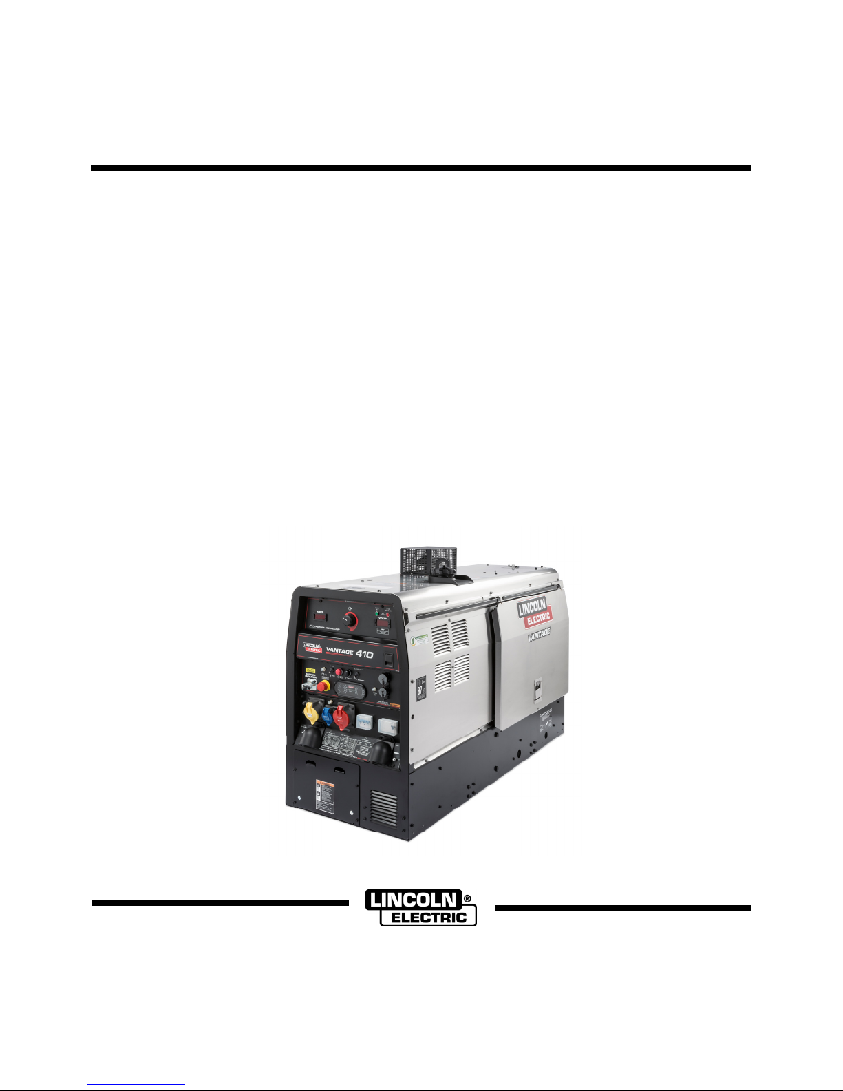
VANTAGE® 410 CE
OPERATOR’S MANUAL
IM2076
09/2017
REV01
ENGLISH
Lincoln Electric Bester Sp. z o.o.
ul. Jana III Sobieskiego 19A, 58-263 Bielawa, Poland
www.lincolnelectric.eu

THE LINCOLN ELECTRIC COMPANY
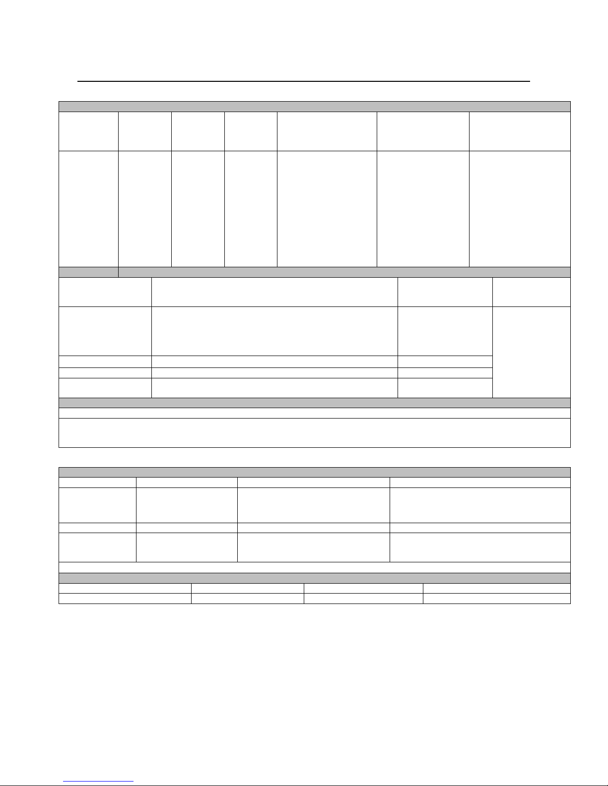
EC DECLARATION OF CONFORMITY
Manufacturer and technical
documentation holder:
EC Company:
Hereby declare that welding equipment:
Product number:
Is in conformity with Council
Directives and amendments:
Standards: EN 60974-1:2012, Safety requirements for arc welding equipment,
Notified body (for 2000/14/EC
Conformity):
Guaranteed sound power level:
Measured sound power level: LWA 94 dB (net power Pel = 9.6 kW)
CE marking affixed in ‘16
Samir Farah, Manufacturer Jacek Stefaniak, European Community Representative
Compliance Engineering Manager European Product Manager Equipment
15August 2017
MCD522b
The Lincoln Electric Company
22801 St. Clair Ave.
Cleveland Ohio 44117-1199 USA
Lincoln Electric Europe S.L.
c/o Balmes, 89 - 8
0 2a
08008 Barcelona SPAIN
Vantage 410 CE
K4178-x (Product number may contain suffixes and prefixes.)
Machinery Directive 2006/42/EC;
Low Voltage Directive (LVD) 2014/35/EU
Electromagnetic Compatibility (EMC) Directive 2014/30/EU;
Noise emission in the environment by equipment for use outdoors
2000/14/EC; & 2005/88/EC
power sources;
EN 60974-10:2014, Arc Welding Equipment-Part 10: Electromagnetic
compatibility (EMC) requirements;
EN ISO 3744:2010, Acoustic – Determination of sound power levels of
noise sources using sound pressure …2010
EN60204-1 (2006): Safety of machinery – Electrical equipment of
machines, Part 1: General requirements.
EN12100 (2010): Safety of machinery – General principles for design
Risk assessment and risk reduction.
AV Technology LTD
Unit 2 Easter Court
Europa Boulevard, Warrington
Cheshire WA5 7ZB
LWA 97 dB (net power Pel = 9.6 kW)
29 August 2017
English English
I

THANKS! For having chosen the QUALITY of the Lincoln Electric products.
Please Examine Package and Equipment for Damage. Claims for material damaged in shipment must be notified
immediately to the dealer.
For future reference record in the table below your equipment identification information. Model Name, Code &
Serial Number can be found on the machine rating plate.
Model Name:
………………...…………………………….…………………………………………………………………………………………..
Code & Serial number:
………………….……………………………………………….. …………………………………………………….……………..
Date & Where Purchased:
…………………………………………………………………... ……………………….…………………………………………..
ENGLISH INDEX
Technical Specifications ...................................................................................................................................................... 1
Electromagnetic Compatibility (EMC) ................................................................................................................................. 3
Safety .................................................................................................................................................................................. 4
Installation and Operator Instructions ................................................................................................................................. 5
Diagrams ........................................................................................................................................................................... 21
WEEE ................................................................................................................................................................................ 30
Suggested Accessories ..................................................................................................................................................... 32
12/05
English English
II
A
(1)
d
Technical Specifications
VANTAGE
Make/Model Description
®
410 (CE) (K4178-1) (Codes 12516, 12635)
Horse
power
@1800
RPM
INPUT – DIESEL ENGINE
Operating
Speed
(RPM)
Displacement Cu. In.
(ltrs.) Bore x Stroke
Inch (mm)
Starting system Capacities
High 1890
Full Load
1800
Low Idle
1350
91.41 (1.5)
Bore and Stroke
3.07 x 3.09 (78x78)
12Vdc Battery and
Starter
(Group 34;Battery 535
cold crank amps)
Battery charger
Fuel: 20 gal (75.7l)
Oil: 6.4 qts. (6.0l)
Radiator Coolant:
7.2 qts. (6.8l)
K4178-1
Kubota*
V1505
4 cylinder
Naturally
aspirated
Water
Cooled
Diesel
Engine
22HP
RATED OUTPUT @ 40°C - WELDER
Max. Weld
Welding Process Welding Output Current/Volatge/Duty Cycle Output Range
OCV@Rated
Load RPM
300A/32V/100%
DC Constant Current
350A/28V/100%
30 TO 410 AMPS
410A/23V/100%
60V
DC Pipe Current 300A/32V/100% 40 TO 300 AMPS
Touch-StartTM TIG 250V/30V/100% 20 TO 250 AMPS
DC Constant Voltage
Arc Gouging
300A/32V/100%
14 TO 32 VOLTS
90 TO 300 AMPS
RATED OUTPUT @ 40°C - GENERATOR
uxiliary Power
60 Hz 230 Volt, 15A 1-Phase
12.500 Watts Peak, /11.000 Watts Continuous,
60 Hz, 400 Volt, 16A, 3-Phase
LIFT BAIL WEIGHT RATOING 2300LBS. (1043 kg) MAXIMUM
ENGINE
LUBRIFICATION EMISSIONS FUEL SYSTEM GOVERNOR
Full Pressure
with Full Flow
Filter
EPA Tier 4
Interim Compliant
Mechanical Fuel Pump, Auto air bleed
system, Electric shutoff solenoid,
Indirect fuel injector.
Mechanical
Electronic
AIR CLEANER ENGINE IDLER MUFFLER ENGINE PROTECTION
Single Element Automatic Idler
Low noise Muffler with spark arrestor:
Made from long life, aluminized steel.
ENGINE WARRANTY: 2 years complete (parts and labor) 3
r
. year major components (parts and labor)
Shutdown on low oil
pressure & high engine
coolant temperature
PHYSICAL DIMENSIONS
Height Width Length Weight
(1)
913mm** 643 mm 1524 mm 488 kg
Output rating in watts is equivalent to volt-amperes at unity power factor. Output voltage is within ± 10% at all loads up
to rated capacity. When welding, available auxiliary power will be reduced.
*Engine warranty may vary outside of the USA. (See Engine warranty for details).
**
To Top of enclosure. Add 7.88'' (200.02mm) to top of exhaust pipe. Add 4.012”(101.9mm) to top of Lift Bail.
(2)
Reduced to less than 30V in the stick mode when VRD (Voltage Reduction Devise) is on.
(2)
English English
1

A
A
MACHINE SPECIFICATIONS
RECEPTACLES
(1) 115V Euro Style
(1) 230V Euro Style
(1) 400V Euro Style
UXILIARY POWER CIRCUIT
BREAKER
(2) 30Amp for Single Phase
(1) 15Amp for Single Phase
(1) 16Amp for Three Phase (3-pole)
OTHER CIRCUIT BREAKERS
10AMP for Engine Battery Charging
Circuit
10AMP for 42V Wire Feeder Power
4-pole, 25AMP x 1
Residual Current Device (RCD)
1 Phase, 15AMP x 1 for 230V
30AMP x 2 for 115V
MISCELLANEOUS
HARMONIC CONTENT EMC CLASSIFICATION
6.2% THF.
VANTAGE 410 CE IS CLASSIFIED AS A CLASS I MACHINE
THF < 8% :
MACHINE AMBIENT OPERATING CONDITIONS
TEMPERATURE
LTITUDE MAX ANGLE OF OPERATION
5°F (-15°C) TO 104°F (+ 40°C) 5997ft (1828m)* 15° ALL DIRECTIONS
* For use above 5997ft (1828m), contact Authorized Field Service Shop.
TRANSPORTATION & STORAGE TEMPERATURES
-13°F (-25°C) TO 131°F (+55°C) NOT EXCEEDING 158° (70°C) FOR 24 HOURS
English English
2
Electromagnetic Compatibility (EMC)
This machine has been designed in accordance with all relevant directives and standards. However, it may still generate
electromagnetic disturbances that can affect other systems like telecommunications (telephone, radio, and television) or
other safety systems. These disturbances can cause safety problems in the affected systems. Read and understand
this section to eliminate or reduce the amount of electromagnetic disturbance generated by this machine.
system, it is responsibility of the installer or user of the equipment to ensure, by consultation with the distribution network
operator if necessary, that the equipment may be connected.
Before installing the machine, the operator must check the work area for any devices that may malfunction because of
electromagnetic disturbances. Consider the following.
Input and output cables, control cables, and telephone cables that are in or adjacent to the work area and the
Radio and/or television transmitters and receivers. Computers or computer controlled equipment.
Safety and control equipment for industrial processes. Equipment for calibration and measurement.
Personal medical devices like pacemakers and hearing aids.
Check the electromagnetic immunity for equipment operating in or near the work area. The operator must be sure
The dimensions of the work area to consider will depend on the construction of the area and other activities that are
Consider the following guidelines to reduce electromagnetic emissions from the machine.
Connect the machine to the input supply according to this manual. If disturbances occur if may be necessary to take
The output cables should be kept as short as possible and should be positioned together. If possible connect the
Shielding of cables in the work area can reduce electromagnetic emissions. This may be necessary for special
The Class A equipment is not intended for use in residential locations where the electrical power is provided by the public
low-voltage supply system. There can be potential difficulties in ensuring electromagnetic compatibility in those locations,
due to conducted as well as radio-frequency disturbances.
This machine has been designed to operate in an industrial area. The operator must install and operate this
equipment as described in this manual. If any electromagnetic disturbances are detected the operator must
put in place corrective actions to eliminate these disturbances with, if necessary, assistance from Lincoln
Electric. This equipment does not comply with IEC 61000-3-12. If it is connected to a public low-voltage
machine.
that all equipment in the area is compatible. This may require additional protection measures.
taking place.
additional precautions such as filtering the input supply.
work piece to ground in order to reduce the electromagnetic emissions. The operator must check that connecting
the work piece to ground does not cause problems or unsafe operating conditions for personnel and equipment.
applications.
WARNING
English English
3
Safety
01/11
WARNING
This equipment must be used by qualified personnel. Be sure that all installation, operation, maintenance and repair
procedures are performed only by qualified person. Read and understand this manual before operating this equipment.
Failure to follow the instructions in this manual could cause serious personal injury, loss of life, or damage to this
equipment. Read and understand the following explanations of the warning symbols. Lincoln Electric is not responsible
for damages caused by improper installation, improper care or abnormal operation.
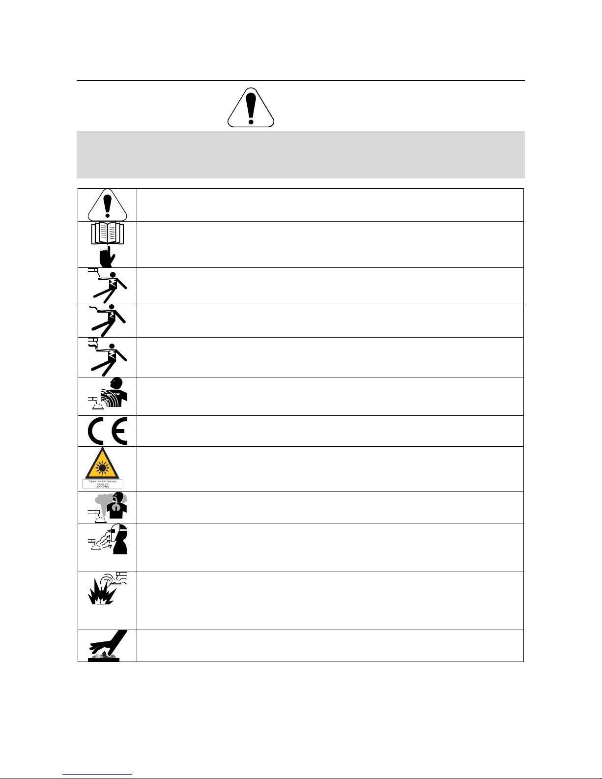
WARNING: This symbol indicates that instructions must be followed to avoid serious personal injury,
loss of life, or damage to this equipment. Protect yourself and others from possible serious injury or
death.
READ AND UNDERSTAND INSTRUCTIONS: Read and understand this manual before operating
this equipment. Arc welding can be hazardous. Failure to follow the instructions in this manual could
cause serious personal injury, loss of life, or damage to this equipment.
ELECTRIC SHOCK CAN KILL: Welding equipment generates high voltages. Do not touch the
electrode, work clamp, or connected work pieces when this equipment is on. Insulate yourself from
the electrode, work clamp, and connected work pieces.
ELECTRICALLY POWERED EQUIPMENT: Turn off input power using the disconnect switch at the
fuse box before working on this equipment. Ground this equipment in accordance with local electrical
regulations.
ELECTRICALLY POWERED EQUIPMENT: Regularly inspect the input, electrode, and work clamp
cables. If any insulation damage exists replace the cable immediately. Do not place the electrode
holder directly on the welding table or any other surface in contact with the work clamp to avoid the
risk of accidental arc ignition.
ELECTRIC AND MAGNETIC FIELDS MAY BE DANGEROUS: Electric current flowing through any
conductor creates electric and magnetic fields (EMF). EMF fields may interfere with some
pacemakers, and welders having a pacemaker shall consult their physician before operating this
equipment.
CE COMPLIANCE: This equipment complies with the European Community Directives.
ARTIFICIAL OPTICAL RADIATION: According with the requirements in 2006/25/EC Directive and
EN 12198 Standard, the equipment is a category 2. It makes mandatory the adoption of Personal
Protective Equipments (PPE) having filter with a protection degree up to a maximum of 15, as
required by EN169 Standard.
FUMES AND GASES CAN BE DANGEROUS: Welding may produce fumes and gases hazardous to
health. Avoid breathing these fumes and gases. To avoid these dangers the operator must use
enough ventilation or exhaust to keep fumes and gases away from the breathing zone.
ARC RAYS CAN BURN: Use a shield with the proper filter and cover plates to protect your eyes from
sparks and the rays of the arc when welding or observing. Use suitable clothing made from durable
flame-resistant material to protect you skin and that of your helpers. Protect other nearby personnel
with suitable, non-flammable screening and warn them not to watch the arc nor expose themselves to
the arc.
WELDING SPARKS CAN CAUSE FIRE OR EXPLOSION: Remove fire hazards from the welding
area and have a fire extinguisher readily available. Welding sparks and hot materials from the welding
process can easily go through small cracks and openings to adjacent areas. Do not weld on any
tanks, drums, containers, or material until the proper steps have been taken to insure that no
flammable or toxic vapors will be present. Never operate this equipment when flammable gases,
vapors or liquid combustibles are present.
WELDED MATERIALS CAN BURN: Welding generates a large amount of heat. Hot surfaces and
materials in work area can cause serious burns. Use gloves and pliers when touching or moving
materials in the work area.
English English
4
SAFETY MARK: This equipment is suitable for supplying power for welding operations carried out in
an environment with increased hazard of electric shock.
CYLINDER MAY EXPLODE IF DAMAGED: Use only compressed gas cylinders containing the
correct shielding gas for the process used and properly operating regulators designed for the gas and
pressure used. Always keep cylinders in an upright position securely chained to a fixed support. Do
not move or transport gas cylinders with the protection cap removed. Do not allow the electrode,
electrode holder, work clamp or any other electrically live part to touch a gas cylinder. Gas cylinders
must be located away from areas where they may be subjected to physical damage or the welding
process including sparks and heat sources.
EQUIPMENT WEIGHT OVER 30kg: Move this equipment with care and with the help of another
person. Lifting may be dangerous for your physical health.
The manufacturer reserves the right to make changes and/or improvements in design without upgrade at the same time
the operator’s manual.
Installation and Operator Instructions
Read this entire section before installation or operation
of the machine.
General Description
The Vantage® 410 CE is a diesel engine powered DC
multi-process welding power source and 115/230V 1ph
and 400V/3ph AC power generator. The engine drives a
generator that supplies three phase power for the DC
welding circuit, single phase and three phase power for
the AC auxiliary outlets. The DC welding control system
uses state of the art Chopper Technology (CT™) for
superior welding performance.
VRD (Voltage Reduction Device)
The VRD feature provides additional safety in the
CC-Stick mode especially in an environment with a
higher risk of electric shock such as wet areas and hot
humid sweaty conditions.
The VRD reduces the OCV (Open Circuit Voltage) at the
welding output terminals while not welding to less than
13VDC when the resistance of the output circuit is
above 200Ω (ohms).
The VRD requires that the welding cable connections be
kept in good electrical condition because poor
connections will contribute to poor starting. Having good
electrical connections also limits the possibility of other
safety issues such as heat-generated damage, burns
and fires.
The machine is shipped with the VRD switch in the “Off”
position. To turn it “On” or “Off”:
Turn the engine “Off”.
Disconnect the negative battery cable.
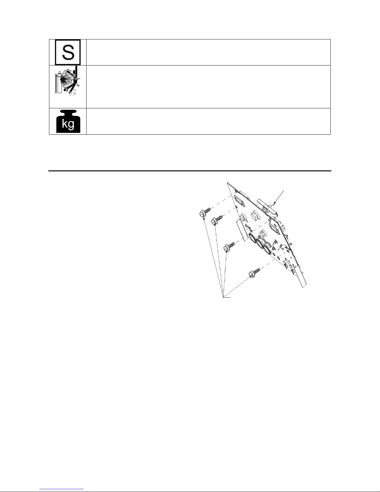
Lower the control panel by removing 4 front panel
screws. (Figure 1)
Place the VRD switch in the “On or “Off” position.
(Figure 1)
With the VRD switch in the “On” position, the VRD lights
are enabled.
REMOVE 4 FRONT PANEL
SCREWS TO ACCESS (VRD)
SWITCH
Figure 1
Location and Ventilation
The welder should be located to provide an unrestricted
flow of clean, cool air to the cooling air inlets and to
avoid restricting the cooling air outlets. Also, locate the
welder so that the engine exhaust fumes are properly
vented to an outside area.
Stacking
VANTAGE® 410 CE machines cannot be stacked.
Angle of Operation
Engines are designed to run in the level condition which
is where the optimum performance is achieved. The
maximum angle of continuous operation is 20 degrees in
all directions, 30 degrees Intermittent (less than 10
minutes continuous) in all directions. If the engine is to
be operated at an angle, provisions must be made for
checking and maintaining the oil level at the normal
(FULL) oil capacity in the crankcase.
When operating the welder at an angle, the effective fuel
capacity will be slightly less than the amount specified.
(VRD)-VOLTAGE
REDUCTION DEVICE
SWITCH IS LOCATED
IN THIS AREA
English English
5

The machines maximum angle of operation is 15° in all
directions.
Lifting
The VANTAGE® 410 CE weighs approximately 1205lbs
(547kg) with a full tank of fuel (1706lbs (488kg) less
fuel). A lift bail is mounted to the machine and should
always be used when lifting the machine.
Falling equipment can cause injury.
Lift only with equipment of adequate
lifting capacity.
Be sure machine is stable when lifting.
Do not lift this machine using lift bail if it is equipped
with a heavy accessory such as trailer or gas
cylinder.
Do not lift machine if lift bail is damaged.
Do not operate machine while suspended from lift
bail.
WARNING
High Altitude Operation
At higher altitudes, output derating may be necessary.
For maximum rating, derate the machine 2.5% to 3.5%
for every 305 m. Due to new EPA and other local
emissions regulations, modifications to the engine for
high altitude are restricted within the United States. For
use above 1828 m an authorized Perkins engine field
service shop should be contacted to determine if any
adjustments can be made for operation in higher
elevations.
High Temperature Operation
At temperatures above 40°C, Welder output derating is
necessary. For maximum output ratings, derate the
welder output 2 volts for every 10°C above 40°C.
Cold Weather Starting
With a fully charged battery and the proper oil, the
engine should start satisfactorily down to -15C°. If the
engine must be frequently started at or below -5°C, it
may be desirable to install cold starting aides. The use
of No. 1D diesel fuel is recommended in place of No. 2D
at temperatures below -5°C. Allow the engine to warm
up before applying a load or switching to high idle.
Note: Extreme cold weather starting may require longer
glow plug operation.
Under no conditions should ether or other starting fluids
be used with this engine!
WARNING
Towing
Use a recommended trailer for use with this equipment
for road, in-plant and yard towing by a vehicle
user adapts a non-Lincoln trailer, he must assume
responsibility that the method of attachment and usage
does not result in a safety hazard or damage the welding
equipment. Some of the factors to be considered are as
follows:
1. Design capacity of trailer vs. weight of Lincoln
equipment and likely additional attachments.
2. Proper support of, and attachment to, the base of
the welding equipment so there will be no undue
stress to the framework.
3. Proper placement of the equipment on the trailer to
insure stability side to side and front to back when
being moved and when standing by itself while
(1)
. If the
being operated or serviced.
4. Typical conditions of use, i.e., travel speed;
roughness of surface on which the trailer will be
operated; environmental conditions; like
maintenance.
5. Conformance with federal, state and local laws
(1)
Consult applicable federal, state and local laws regarding
specific requirements for use on public highways.
(1)
Vehicle Mounting
Improperly mounted concentrated loads may cause
unstable vehicle handling and tires or other components
to fail.
Only transport this Equipment on serviceable
vehicles which are rated and designed for such
loads.
Distribute, balance and secure loads so vehicle is
stable under conditions of use.
Do not exceed maximum rated loads for compo-
nents such as suspension, axles and tires.
Mount equipment base to metal bed or frame of
vehicle.
Follow vehicle manufacturer’s instructions.
WARNING
Pre-Operation Engine Service
Read the engine operating and maintenance instructions
supplied with this machine.
WARNING
Stop engine and allow to cool before fueling
Do not smoke when fueling.
Fill fuel tank at a moderate rate and do not over-fill.
Wipe up spilled fuel and allow fumes to clear before
starting engine.
Keep sparks and flame away from tank.
Oil
The Vantage®410 CE is shipped with the engine
crankcase filled with high quality SAE 10W-30. Oil that
meets classification CG-4 or CH-4 for diesel engines.
Check the oil level before starting the engine. If it is not
up to the full mark on the dip stick, add oil as required.
Check the oil level every four hours of running time
during the first 50 running hours. Refer to the engine
Operator’s Manual for specific oil recommendations and
break-in information. The oil change interval is
dependent on the quality of the oil and the operating
environment. Refer to the Engine Operator’s Manual for
more details on the proper service and maintenance
intervals.
Fuel
DIESEL FUEL ONLY-Low sulphur fuel or ultra low
sulphur fuel in U.S.A. and Canada.
WARNING
Fill the fuel tank with clean, fresh fuel. The capacity of
the tank is 20 gals 75.7l. When the fuel gauge reads
empty the tank contains approximately 7.6 l of reserve
fuel.
Note: A fuel shut off valve is located on the pre-filter/
sediment filter. Which should be in the closed position
when the welder is not used for extended periods of
time.
English English
6

Engine Cooling System
Air to cool the engine is drawn in the side and exhausted
through radiator & case back. It is important that the
intake and exhaust air is not restricted. Allow a
minimum clearance of 0.6m from the case back and
406mm from either side of the base to a vertical surface.
WARNING
Battery Connection
Use caution as the electrolyte is a strong acid that can
burn skin and damage eyes.
The Vantage
battery cable disconnected. Make certain that the RUNSTOP switch is in the STOP position. Remove the two
screws from the battery tray using a screwdriver or a
10mm socket. Attach the negative battery cable to the
negative battery terminal and tighten using a 13mm
socket or wrench.
Note: This machine is furnished with a wet charged
battery; if unused for several months, the battery may
require a booster charge. Be careful to charge the
battery with the correct polarity. (See Battery in
“Maintenance Section”)
®
410 CE is shipped with the negative
WARNING
Spark Arrester
Some laws may require that gasoline or diesel engines
be equipped with exhaust spark arresters when they are
operated in certain locations where unarrested sparks
may present a fire hazard. The standard muffler included
with this welder has a spark arrestor mounted to the
muffler outlet. This device also enables the machine to
conform to the sound power requirements of the
European Union and should not be removed unless of
cleaning. Please note: compliance to CE sound power is
achieved with spark arrestor installed.
An incorrect spark arrestor may lead to damage to the
engine or adversely affect performance.
WARNING
Remote Control
The Vantage® 410 CE is equipped with a 6-pin and a 14pin connector. When in the Arc Gouging or CV-WIRE
modes and when a remote control is connected to the 6pin Connector, the auto-sensing circuit automatically
switches the OUTPUT control from control at the welder
to remote control.
When in TOUCH START TIG mode and when a Amptrol
is connected to the 6-Pin Connector, the OUTPUT dial is
used to set the maximum current range of the
CURRENT CONTROL of the Amptrol.
When in the CC-STICK or DOWNHILL PIPE mode and
when REMOTE CONTROL is connected to the 6-Pin or
14-pin Connector, the OUTPUT CONTROL dial is used
to set the maximum current range of the OUTPUT
CONTROL of the REMOTE.
EXAMPLE: When the OUTPUT CONTROL on the
welder is set to 200 amps the current range on the
remote control will be Min.- 200 amps, rather than the
full Min.-Max. amps. Any current range that is less than
the full range provides finer current resolution for more
fine tuning of the output.
The 14-pin connector is used to directly connect a wire
feeder control cable. In the CV-WIRE mode, if the feeder
being used has a voltage control when the wire feeder
control cable is connected to the 14-Pin Connector, the
auto-sensing circuit automatically makes OUTPUT
CONTROL inactive and the wire feeder voltage control
active. Otherwise, the OUTPUT CONTROL is used to
preset the voltage.
NOTE: When a wire feeder with a built in welding
voltage control is connected to the 14-pin connector, do
not connect anything to the 6-pin connector.
WARNING
Electrical Connections
Machine Grounding
Because this portable engine driven welder creates its
own power, it is not necessary to connect its frame to an
earth ground, unless the machine is connected to
premises wiring (home, shop, etc.).
To prevent dangerous electric shock, other equipment to
which this engine driven welder supplies power must:
Be grounded to the frame of the welder using a
grounded type plug or be double insulated.
Be double insulated.
Do not ground the machine to a pipe that carries
explosive or combustible material.
When this welder is mounted on a truck or trailer, its
frame must be electrically bonded to the metal frame of
the vehicle. Use a 8mm
connected between the machine grounding stud and the
frame of the vehicle. When this engine driven welder is
connected to premises wiring such as that in a home or
shop, its frame must be connected to the system earth
ground. See further connection instructions in the
section entitled "Standby Power Connections" as well as
the article on grounding in the latest National Electrical
Code and the local code.
In general, if the machine is to be grounded, it should be
connected with a 8mm
earth ground such as a metal water pipe going into the
ground for at least ten feet and having no insulated
joints, or to the metal framework of a building which has
been effectively grounded.
The National Electrical Code lists a number of alternate
means of grounding electrical equipment. A machine
grounding stud marked with the symbol
on the front of the welder.
WARNING
2
or larger copper wire
2
or larger copper wire to a solid
is provided
Welding Terminals
The Vantage®410 CE is equipped with a toggle switch
for selecting "hot" welding terminal when in the "WELD
TERMINALS ON" position or "cold" welding terminal
when in the "REMOTLY CONTROLLED" position.
Welding Output Cables
With the engine off connect the electrode and work
cables to the output studs. The welding process dictates
the polarity of the electrode cable. These connections
should be checked periodically and tightened with a
19mm wrench.
English English
7

Table below lists recommended cable sizes and lengths
for rated current and duty cycle. Length refers to the
distance from the welder to the work and back to the
welder. Cable diameters are increased for long cable
lengths to reduce voltage drops.
Total Combined Length of Electrode and Work
Cable Length Cable Size for 400 A @
0-30 meters 2/0 AWG (67,4mm2)
30-46 meters 2/0 AWG (67,4mm2)
46-61 meters 3/0 AWG (85mm2)
Cables
60%Duty Cycle
Cable Installation
Install the welding cables to your Vantage® 410 CE as
follows:
1. The engine must be OFF to install welding cables.
2. Remove the flanged nuts from the output terminals.
3. Connect the electrode holder and work cables to the
weld output terminals. The terminals are identified
on the case front.
4. Tighten the flanged nuts securely.
5. Be certain that the metal piece you are welding (the
“work”) is properly connected to the work clamp and
cable.
6. Check and tighten the connections periodically.
WARNING
Loose connections will cause the output terminals to
overheat. The terminals may eventually melt.
Do not cross the welding cables at the output
terminal connection. Keep the cables isolated and
separate from one another.
Auxiliary Power
The auxiliary power capacity is 12500W Peak, 11000W
continuous of 60Hz, single phase power. The auxiliary
power capacity rating in watts is equivalent to voltamperes at unity power factor. The max permissible
current of the 400 VAC output is 16A. Output voltage is
within ±10% at all loads up to the rated capacity.
Single phase power is:
3,500 Watts Peak / 3,500 Watts Continuous, 60 Hz
230 Volts 1-Phase (Euro).
Standby Power Connections
The machine is suitable for temporary, standby or
emergency power using the engine manufacturer's
recommended maintenance schedule.
The machine can be permanently installed as a standby
power unit for 400 VAC, three phase, 16A service
Connections must be made by a licensed electrician who
can determine how the power can be adapted to the
particular installation and comply with all applicable
electrical codes.
Take necessary steps to assure load is limited to
the capacity of the Vantage
®
410 CE.
Connection of Lincoln Electric Wire
Feeders
Shut off welder before making any electrical
connections.
WARNING
Connection of the LN-7 or LN-8 to the Vantage®
410 CE.
1. Shut the welder off.
2. Connect the LN-7 or LN-8 per instructions on the
appropriate Section "Diagram".
3. Set the "WIRE FEEDER VOLTMETER" switch to
either "+" or "-" as required by the electrode being
used.
4. Set the "MODE" switch to the "CV WIRE " position.
5. Set the "ARC CONTROL" knob to "0" initially and
adjust to suit.
6. Set the "WELD TERMINALS" switch to the
"REMOTELY CONTROLLED" position.
7. Set the "IDLE" seitch to the "HIGH" position.
Connection of LN-15 to the Vantage® 410 CE
1. Shut the welder off.
2. For electrode Positive, connect the electrode cable
to the "+" terminal of the welder and work cable to
the "-" terminal of the welder. For electrode
Negative, connect the electrode cable to the "-"
terminal of the welder and work cable to the "+"
terminal of the welder.
3. Choose Model:
Across The-Arc Model:
4. Attach the single lead from the front of the LN-15 to
work using the spring clip at the end of the lead.
This is a control lead to supply current to the wire
feeder motor; it does not carry welding current.
5. Set the "WELD TERMINALS" switch to "WELD
TERMINALS ON".
6. When the gun trigger is closed, the current sensing
circuit will cause the Vantage
to the high idle speed, the wire will begin to feed
and the welding process started. When welding is
stopped, the engine will revert to low idle speed
after approximately 12 seconds unless welding is
resumed.
®
410 CE engine to go
Control Cable Model:
4. Connect Control Cable between Engine Welder and
Feeder.
5. Set the "WELD TERMINALS" switch to
"REMOTELY CONTROLLED".
6. Set the MODE switch to thr "CV-WIRE" position.
7. Set the "WIRE FEEDER VOLTMETER" switch to
either "+" or "-" as required by the electrode polarity
being used.
8. Set the "ARC CONTROL" knob to "0" initially and
adjust to suit.
9. Set the "IDLE" switch to the "AUTO" position.
10. When the gun trigger is closed, the current sensing
circuit will cause the Vantage
to the high idle speed, the wire will begin to feed
and the welding process started. When welding is
stopped, the engine will revert to low idle speed
after approximately 12 seconds unless welding is
resumed.
®
410 CE engine to go
Connection of the LN-25 to the Vantage® 410
CE
The LN-25 with or without an internal contactor may be
used with the Vantage
"Diagram" Section.
NOTE: The LN-25 (K431) Remote Control Module and
(K432) Remote Cable are not recommended for use with
the Vantage
®
410 CE
®
410 CE. See the appropriate
English English
8
 Loading...