

Lincoln Electric VANTAGE 400 AU 11959, VANTAGE 400 AU 12307 Operator's Manual
Operator’s Manual
VANTAGE
®
400 (AU)
Register your machine:
www.lincolnelectric.com/register
Authorized Service and Distributor Locator:
www.lincolnelectric.com/locator
IM10140-B | Issue D ate 08/14
© Lincoln Global, Inc. All Rights Reserved.
For use with machines having Code Numbers:
11959, 12307
Need Help? Call 1.888.935.3877
to talk to a Service Representative
Hours of Operation:
8:00 AM to 6:00 PM (ET) Mon. thru Fri.
After hours?
Use “Ask the Experts” at lincolnelectric.com
A Lincoln Service Representative will contact you
no later than the following business day.
For Service outside the USA:
Email: globalservice@lincolnelectric.com
Save for future reference
Date Purchased
Code: (ex: 10859)
Serial: (ex: U1060512345)
THANK YOU FOR SELECTING
A QUALITY PRODUCT BY
LINCOLN ELEC TRIC.
PLEASE EXAMINE CARTON AND EQUIPMENT FOR
DAMAGE IMMEDIATELY
When this equipment is shipped, title passes to the purchaser upon
receipt by the carrier. Consequently, Claims for material damaged in
shipment must be made by the purchaser against the transportation
company at the time the shipment is received.
SAFETY DEPENDS ON YOU
Lincoln arc welding and cutting equipment is designed and built with
safety in mind. However, your overall safety can be increased by
proper installation ... and thoughtful operation on your part.
DO NOT INSTALL, OPERATE OR REPAIR THIS EQUIPMENT
WITHOUT READING THIS MANUAL AND THE SAFETY PRECAUTIONS
CONTAINED THROUGHOUT. And, most importantly, think before you
act and be careful.
This statement appears where the information must be followed
exactly to avoid serious personal injury or loss of life.
This statement appears where the information must be followed to
avoid minor personal injury or damage to this equipment.
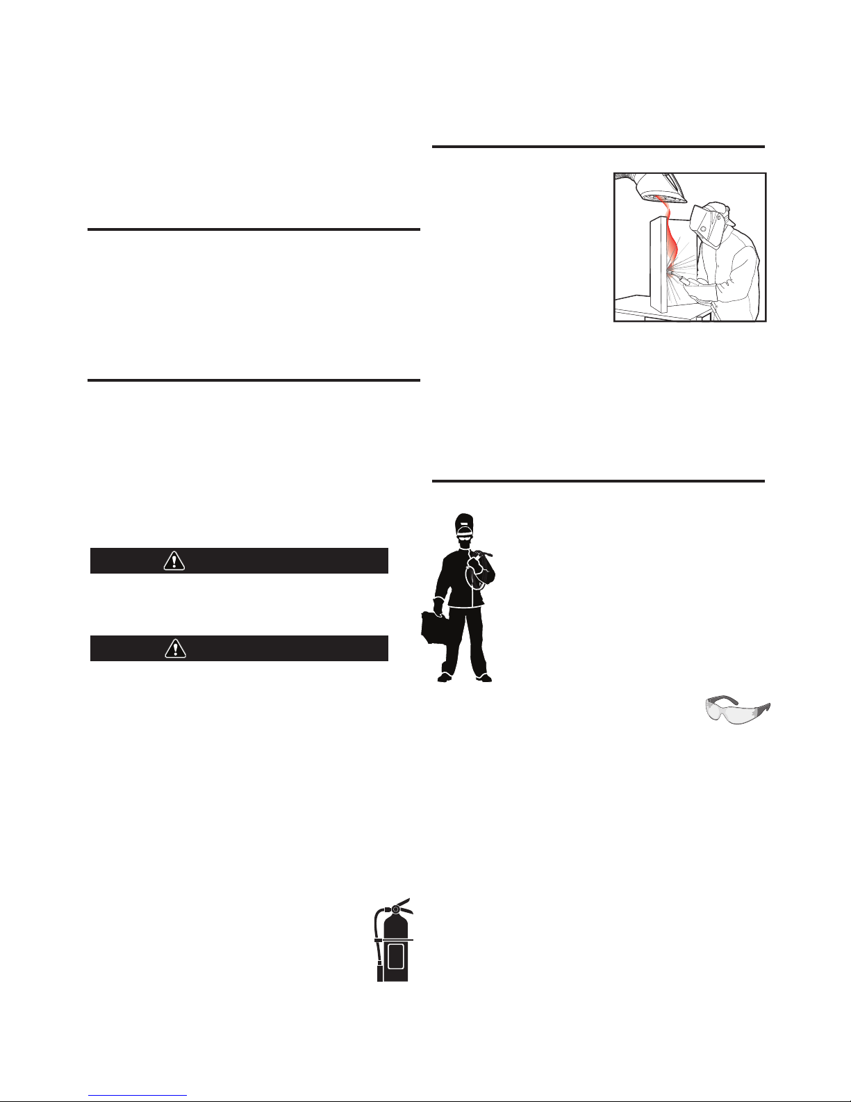
KEEP YOUR HEAD OUT OF THE FUMES.
DON’T get too close to the arc. Use
c
orrective lenses if necessary to
stay a reasonable distance away
from the arc.
READ and obey the Material Safety
Data Sheet (MSDS) and the warning
label that appears on all containers
of welding materials.
USE ENOUGH VENTILATION or
exhaust at the arc, or both, to keep
the fumes and gases from your breathing zone and the general area.
IN A LARGE ROOM OR OUTDOORS, natural ventilation may be
adequate if you keep your head out of the fumes (See below).
USE NATURAL DRAFTS or fans to keep the fumes away from your
face.
If you de velop unusual symptoms, see your supervisor. Perhaps the
welding atmosphere and ventilation system should be checked.
WEAR CORRECT EYE, EAR & BODY PROTECTION
PROTECT your eyes and face with welding helmet
properly fitted and with proper grade of filter plate
(See ANSI Z49.1).
PROTECT your body from welding spatter and arc
flash with protective clothing including woolen
clothing, flame-proof apron and gloves, leather
leggings, and high boots.
PROTECT others from splatter, flash, and glare with
protective screens or barriers.
IN SOME AREAS, protection from noise may be
appropriate.
BE SURE protective equipment is in good condition.
Also, wear safety glasses in work area AT ALL
TIMES.
SPECIAL SITUATIONS
DO NOT WELD OR CUT containers or materials which previously had
been in contact with hazardous substances unless they are properly
cleaned. This is extremely dangerous.
DO NOT WELD OR CUT painted or plated parts unless special
precautions with ventilation have been taken. They can release highly
toxic fumes or gases.
Additional precautionary measures
PROTECT compressed gas cylinders from excessive heat, mechanical
shocks, and arcs; fasten cylinders so they cannot fall.
BE SURE cylinders are never grounded or part of an electrical circuit.
REMOVE all potential fire hazards from welding area.
ALWAYS HAVE FIRE FIGHTING EQUIPMENT READY FOR
IMMEDIATE USE AND KNOW HOW TO USE IT.
WARNING
CAUTION
SECTION A:
WARNINGS
CALIFORNIA PROPOSITION 65 WARNINGS
Diesel Engines
Diesel engine exhaust and some of its constituents are known
to the State of California to cause cancer, birth defects, and other
reproductive harm.
Gasoline Engines
The engine exhaust from this product contains chemicals known
to the State of California to cause cancer, birth defects, or other
reproductive harm.
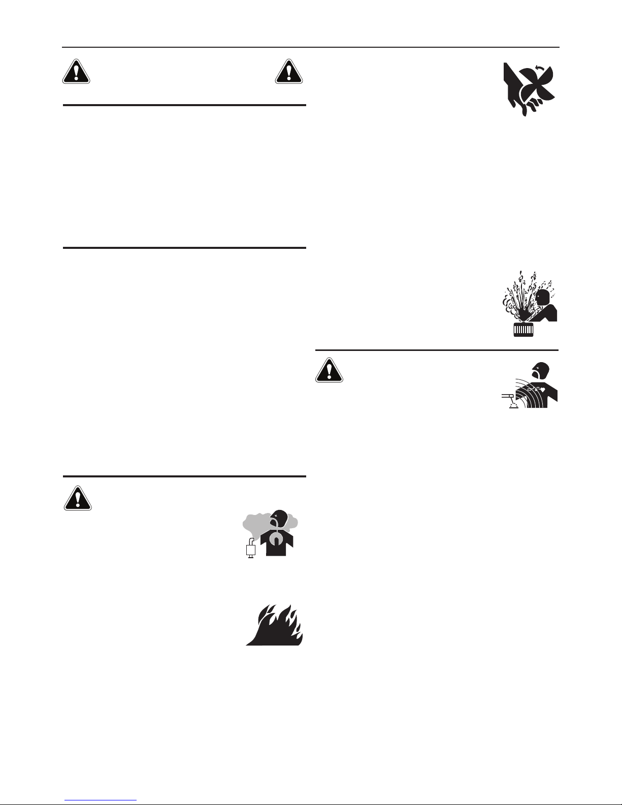
ARC WELDING CAN BE HAZARDOUS. PROTECT
YOURSELF AND OTHERS FROM POSSIBLE SERIOUS
INJURY OR DEATH. KEEP CHILDREN AWAY. PACEMAKER WEARERS SHOULD CONSULT WITH THEIR
DOCTOR BEFORE OPERATING.
Read and understand the following safety highlights. For additional
safety information, it is strongly recommended that you purchase a
copy of “Safety in Welding & Cutting - ANSI Standard Z49.1” from the
American Welding Society, P.O. Box 351040, Miami, Florida 33135 or
CSA Standard W117.2-1974. A Free copy of “Arc Welding Safety”
booklet E205 is available from the Lincoln Electric Company, 22801
St. Clair Avenue, Cleveland, Ohio 44117-1199.
BE SURE THAT ALL INSTALLATION, OPERATION,
MAINTENANCE AND REPAIR PROCEDURES ARE
PERFORMED ONLY BY QUALIFIED INDIVIDUALS.
FOR ENGINE POWERED
EQUIPMENT.
1.a. Turn the engine off before troubleshooting
and maintenance work unless the
maintenance work requires it to be running.
1.b. Operate engines in open, well-ventilated areas or vent the engine
exhaust fumes outdoors.
1.c. Do not add the fuel near an open flame
welding arc or when the engine is running.
Stop the engine and allow it to cool before
refueling to prevent spilled fuel from
vaporizing on contact with hot engine parts
and igniting. Do not spill fuel when filling tank. If fuel is spilled,
wipe it up and do not start engine until fumes have been
eliminated.
1.d. Keep all equipment safety guards, covers and
devices in position and in good repair.Keep
hands, hair, clothing and tools away from
V-belts, gears, fans and all other moving parts
when starting, operating or repairing
e
quipment.
1.e. In some cases it may be necessary to remove safety guards to
p
erform required maintenance. Remove guards only when
necessary and replace them when the maintenance requiring
their removal is complete. Always use the greatest care when
working near moving parts.
1.f. Do not put your hands near the engine fan. Do not attempt to
override the governor or idler by pushing on the throttle control
rods while the engine is running.
1.g. To prevent accidentally starting gasoline engines while turning
the engine or welding generator during maintenance work,
disconnect the spark plug wires, distributor cap or magneto wire
as appropriate.
1.h. To avoid scalding, do not remove the radiator
pressure cap when the engine is
hot.
ELECTRIC AND
MAGNETIC FIELDS MAY
BE DANGEROUS
2.a. Electric current flowing through any conductor
causes localized Electric and Magnetic Fields (EMF). Welding
current creates EMF fields around welding cables and welding
machines
2.b. EMF fields may interfere with some pacemakers, and welders
having a pacemaker should consult their physician before
welding.
2.c. Exposure to EMF fields in welding may have other health effects
which are now not known.
2.d. All welders should use the following procedures in order to
minimize exposure to EMF fields from the welding circuit:
2.d.1. Route the electrode and work cables together - Secure
them with tape when possible.
2.d.2. Never coil the electrode lead around your body.
2.d.3. Do not place your body between the electrode and work
cables. If the electrode cable is on your right side, the
work cable should also be on your right side.
2.d.4. Connect the work cable to the workpiece as close as possible to the area being welded.
2.d.5. Do not work next to welding power source.
3
SAFETY

ELECTRIC SHOCK
CAN KILL.
3.a. The electrode and work (or ground) circuits are
electrically “hot” when the welder is on. Do
n
ot touch these “hot” parts with your bare skin or wet clothing.
Wear dry, hole-free gloves to insulate hands.
3.b. Insulate yourself from work and ground using dry insulation.
Make certain the insulation is large enough to cover your full area
of physical contact with work and ground.
In addition to the normal safety precautions, if
welding must be performed under electrically
hazardous conditions (in damp locations or while
wearing wet clothing; on metal structures such as
floors, gratings or scaffolds; when in cramped
positions such as sitting, kneeling or lying, if there
is a high risk of unavoidable or accidental contact
with the workpiece or ground) use the following
equipment:
• Semiautomatic DC Constant Voltage (Wire) Welder.
• DC Manual (Stick) Welder.
• AC Welder with Reduced Voltage Control.
3.c. In semiautomatic or automatic wire welding, the electrode,
electrode reel, welding head, nozzle or semiautomatic welding
gun are also electrically “hot”.
3.d. Always be sure the work cable makes a good electrical
connection with the metal being welded. The connection should
be as close as possible to the area being welded.
3.e. Ground the work or metal to be welded to a good electrical (earth)
ground.
3.f. Maintain the electrode holder, work clamp, welding cable and
welding machine in good, safe operating condition. Replace
damaged insulation.
3.g. Never dip the electrode in water for cooling.
3.h. Never simultaneously touch electrically “hot” parts of electrode
holders connected to two welders because voltage
between the
two can be the total of the open circuit voltage of both
welders.
3.i. When working above floor level, use a safety belt to protect
yourself from a fall should you get a shock.
3.j. Also see It ems 6.c. and 8.
ARC RAYS CAN BURN.
4.a. Use a shield with the proper filter and cover plates to protect your
eyes from sparks and the rays of the arc when welding or
o
bserving open arc welding. Headshield and filter lens should
conform to ANSI Z87. I standards.
4.b. Use suitable clothing made from durable flame-resistant material
to protect your skin and that of your helpers from the arc rays.
4.c. Protect other nearby personnel with suitable, non-flammable
screening and/or warn them not to watch the arc nor expose
themselves to the arc rays or to hot spatter or metal.
FUMES AND GASES
CAN BE DANGEROUS.
5.a. Welding may produce fumes and gases
hazardous to health. Avoid breathing these fumes and gases.
When welding, keep your head out of the fume. Use enough
ventilation and/or exhaust at the arc to keep fumes and gases
away from the breathing zone. When welding with
electrodes which require special ventilation such
as stainless or hard facing (see instructions on
container or MSDS) or on lead or cadmium plated
steel and other metals or coatings which produce
highly toxic fumes, keep exposure as low as
possible and within applicable OSHA PEL and
ACGIH TLV limits using local exhaust or
mechanical ventilation. In confined spaces or in
some circumstances, outdoors, a respirator may
be required. Additional precautions are also
required when welding on galvanized steel.
5. b. The operation of welding fume control equipment is affected by
various factors including proper use and positioning of the
equipment, maintenance of the equipment and the specific
welding procedure and application involved. Worker exposure
level should be checked upon installation and periodically
thereafter to be certain it is within applicable OSHA PEL and
ACGIH TLV limits.
5.c. Do not weld in locations near chlorinated hydrocarbon vapors
coming from degreasing, cleaning or spraying operations. The
heat and rays of the arc can react with solvent vapors to form
phosgene, a highly toxic gas, and other irritating products.
5.d. Shielding gases used for arc welding can displace air and
cause
injury or death. Always use enough ventilation, especially in
confined areas, to insure breathing air is safe.
5.e. Read and understand the manufacturer’s instructions for this
equipment and the consumables to be used, including the
material safety data sheet (MSDS) and follow your employer’s
safety practices. MSDS forms are available from your welding
distributor or from the manufacturer.
5.f. Also see item 1.b.
4
SAFETY

WELDING AND CUTTING
SPARKS CAN CAUSE
FIRE OR EXPLOSION.
6.a. Remove fire hazards from the welding area. If
t
his is not possible, cover them to prevent the welding sparks
from starting a fire. Remember that welding sparks and hot
materials from welding can easily go through small cracks and
openings to adjacent areas. Avoid welding near hydraulic lines.
Have a fire extinguisher readily available.
6.b. Where compressed gases are to be used at the job site, special
precautions should be used to prevent hazardous situations.
Refer to “Safety in Welding and Cutting” (ANSI Standard Z49.1)
and the operating information for the equipment being used.
6.c. When not welding, make certain no part of the electrode circuit is
touching the work or ground. Accidental contact can cause
overheating and create a fire hazard.
6.d. Do not heat, cut or weld tanks, drums or containers until the
proper steps have been taken to insure that such procedures will
not cause flammable or toxic vapors from substances inside.
They can cause an explosion even though they have been
“cleaned”. For information, purchase “Recommended Safe
Practices for the Preparation for Welding and Cutting of
Containers and Piping That Have Held Hazardous Substances”,
AWS F4.1 from the American Welding Society (see address
above).
6.e. Vent hollow castings or containers before heating, cutting or
welding. They may explode.
6.f. Sparks and spatter are thrown from the welding arc. Wear oil free
protective garments such as leather gloves, heavy shirt, cuffless
trousers, high shoes and a cap over your hair. Wear ear plugs
when welding out of position or in confined places. Always wear
safety glasses with side shields when in a welding area.
6.g. Connect the work cable to the work as close to the welding area
as practical. Work cables connected to the building framework or
other locations away from the welding area increase the
possibility of the welding current passing through lifting chains,
crane cables or other alternate circuits. This can create fire
hazards or overheat lifting chains or cables until they fail.
6.h. Also see item 1.c.
6.I. Read and follow NFPA 51B “ Standard for Fire Prevention During
Welding, Cutting and Other Hot Work”, available from NFPA, 1
Batterymarch Park, PO box 9101, Quincy, Ma 022690-9101.
6.j. Do not use a welding power source for pipe thawing.
CYLINDER MAY EXPLODE IF
DAMAGED.
7.a. Use only compressed gas cylinders containing
the correct shielding gas for the process used
a
nd properly operating regulators designed for
the gas and pressure used. All hoses, fittings,
etc. should be suitable for the application and
maintained in good condition.
7.b. Always keep cylinders in an upright position securely chained to
an undercarriage or fixed support.
7.c. Cylinders should be located:
• Away from areas where they may be struck or subjected
to physical damage.
• A safe distance from arc welding or cutting operations
and any other source of heat, sparks, or flame.
7.d. Never allow the electrode, electrode holder or any other
electrically “hot” parts to touch a cylinder.
7.e. Keep your head and face away from the cylinder valve outlet
when opening the cylinder valve.
7.f. Valve protection caps should always be in place and hand tight
except when the cylinder is in use or connected for use.
7.g. Read and follow the instructions on compressed gas cylinders,
associated equipment, and CGA publication P-l, “Precautions for
Safe Handling of Compressed Gases in
Cylinders,” available
from the Compressed Gas Association 1235 Jefferson Davis
Highway, Arlington, VA 22202.
FOR ELECTRICALLY
POWERED EQUIPMENT.
8.a. Turn off input power using the disconnect
switch at the fuse box before working on the
equipment.
8.b. Install equipment in accordance with the U.S. National Electrical
Code, all local codes and the manufacturer’s recommendations.
8.c. Ground the equipment in accordance with the U.S. National
Electrical Code and the manufacturer’s recommendations.
Refer to
http://www.lincolnelectric.com/safety
for additional safe-
ty information.
5
SAFETY
Welding Safety
Interactive Web Guide
for mobile devices

v
SAFETY
v
Electromagnetic Compatibility (EMC)
Conformance
Products displaying the CE mark are in conformity with European Community Council Directive of 15 Dec
2004 on the approximation of the laws of the Member States relating to electromagnetic compatibility,
2004/108/EC. It was manufactured in conformity with a national standard that implements a harmonized
standard: EN 60974-10 Electromagnetic Compatibility (EMC) Product Standard for Arc Welding Equipment.
It is for use with other Lincoln Electric equipment. It is designed for industrial and professional use.
Introduction
All electrical equipment generates small amounts of electromagnetic emission. Electrical emission may be
transmitted through power lines or radiated through space, similar to a radio transmitter. When emissions
are received by other equipment, electrical interference may result. Electrical emissions may affect many
kinds of electrical equipment; other nearby welding equipment, radio and TV reception, numerical controlled
machines, telephone systems, computers, etc.
WARNING: This equipment is not intended for use in residential locations where the electrical power is provided by the public low-voltage supply system. There may be potential difficulties in ensuring electromagnetic compatibility in those locations, due to conducted as well as radiated disturbances.
Installation and Use
The user is responsible for installing and using the welding equipment according to the manufacturer’s
instructions. If electromagnetic disturbances are detected then it shall be the responsibility of the user of the
welding equipment to resolve the situation with the technical assistance of the manufacturer. In some cases
this remedial action may be as simple as earthing (grounding) the welding circuit, see Note. In other cases it
could involve construction of an electromagnetic screen enclosing the power source and the work complete
with associated input filters. In all cases electromagnetic disturbances must be reduced to the point where
they are no longer troublesome.
Note: The welding circuit may or may not be earthed for safety reasons. Follow your local and
national standards for installation and use. Changing the earthing arrangements should only
be authorized by a person who is competent to assess whether the changes will increase the
risk of injury, e.g., by allowing parallel welding current return paths which may damage the
earth circuits of other equipment.
Assessment of Area
Before installing welding equipment the user shall make an assessment of potential electromagnetic problems in the surrounding area. The following shall be taken into account:
a) other supply cables, control cables, signaling and telephone cables; above, below and adjacent to the
welding equipment;
b) radio and television transmitters and receivers;
c) computer and other control equipment;
d) safety critical equipment, e.g., guarding of industrial equipment;
e) the health of the people around, e.g., the use of pacemakers and hearing aids;
f) equipment used for calibration or measurement;
g) the immunity of other equipment in the environment. The user shall ensure that other equipment being
used in the environment is compatible. This may require additional protection measures;
h) the time of day that welding or other activities are to be carried out.

v
i
SAFETY
v
i
Electromagnetic Compatibility (EMC)
The size of the surrounding area to be considered will depend on the structure of the building and other
activities that are taking place. The surrounding area may extend beyond the boundaries of the premises.
Methods of Reducing Emissions
Public Supply System
Welding equipment should be connected to the public supply system according to the manufacturer’s recommendations. If interference occurs, it may be necessary to take additional precautions such as filtering of
the public supply system. Consideration should be given to shielding the supply cable of permanently
installed welding equipment, in metallic conduit or equivalent. Shielding should be electrically continuous
throughout its length. The shielding should be connected to the welding power source so that good electrical
contact is maintained between the conduit and the welding power source enclosure.
Maintenance of the Welding Equipment
The welding equipment should be routinely maintained according to the manufacturer’s recommendations.
All access and service doors and covers should be closed and properly fastened when the welding equipment is in operation. The welding equipment should not be modified in any way except for those changes
and adjustments covered in the manufacturers instructions. In particular, the spark gaps of arc striking and
stabilizing devices should be adjusted and maintained according to the manufacturer’s recommendations.
Welding Cables
The welding cables should be kept as short as possible and should be positioned close together, running at
or close to floor level.
Equipotential Bonding
Bonding of all metallic components in the welding installation and adjacent to it should be considered.
However, metallic components bonded to the work piece will increase the risk that the operator could
receive a shock by touching these metallic components and the electrode at the same time. The operator
should be insulated from all such bonded metallic components.
Earthing of the Workpiece
Where the workpiece is not bonded to earth for electrical safety, nor connected to earth because of its size
and position, e.g., ship’s hull or building steelwork, a connection bonding the workpiece to earth may reduce
emissions in some, but not all instances. Care should be taken to prevent the earthing of the workpiece
increasing the risk of injury to users, or damage to other electrical equipment. Where necessary, the connection of the workpiece to earth should be made by a direct connection to the workpiece, but in some countries
where direct connection is not permitted, the bonding should be achieved by suitable capacitance, selected
according to national regulations.
Screening and Shielding
Selective screening and shielding of other cables and equipment in the surrounding area may alleviate problems of interference. Screening of the entire welding installation may be considered for special applications
1.
_________________________
1
Portions of the preceding text are contained in EN 60974-10: “Electromagnetic Compatibility (EMC) product standard for arc welding equipment.”
v
ii
v
ii
Thank You
for selecting a QUALITY product by Lincoln Electric. We want you
to take pride in operating this Lincoln Electric Company product
•
•• as much pride as we have in bringing this product to you!
Read this Operators Manual completely before attempting to use this equipment. Save this manual and keep it
handy for quick reference. Pay particular attention to the safety instructions we have provided for your protection.
The level of seriousness to be applied to each is explained below:
WARNING
This statement appears where the information must be followed exactly to avoid serious personal injury or loss of life.
This statement appears where the information must be followed to avoid minor personal injury or damage to this equipment.
CAUTION
Please Examine Carton and Equipment For Damage Immediately
When this equipment is shipped, title passes to the purchaser upon receipt by the carrier. Consequently,
Claims for material damaged in shipment must be made by the purchaser against the transportation company
at the time the shipment is received.
Please record your equipment identification information below for future reference. This information can be
found on your machine nameplate.
Product _________________________________________________________________________________
Model Number ___________________________________________________________________________
Code Number or Date Code_________________________________________________________________
Serial Number____________________________________________________________________________
Date Purchased___________________________________________________________________________
Where Purchased_________________________________________________________________________
Whenever you request replacement parts or information on this equipment, always supply the information you
have recorded above. The code number is especially important when identifying the correct replacement parts.
On-Line Product Registration
- Register your machine with Lincoln Electric either via fax or over the Internet.
• For faxing: Complete the form on the back of the warranty statement included in the literature packet
accompanying this machine and fax the form per the instructions printed on it.
• For On-Line Registration: Go to our
WEBSITE at www.lincolnelectric.com. Choose “Support” and then “Register
Your Product”. Please complete the form and submit your registration.
CUSTOMER ASSISTANCE POLICY
The business of The Lincoln Electric Company is manufacturing and selling high quality welding equipment, consumables, and cutting equipment. Our challenge is to meet the needs of our customers and to exceed their expectations. On occasion, purchasers may ask Lincoln
Electric for advice or information about their use of our products. We respond to our customers based on the best information in our possession at that time. Lincoln Electric is not in a position to warrant or guarantee such advice, and assumes no liability, with respect to such information or advice. We expressly disclaim any warranty of any kind, including any warranty of fitness for any customer’s particular purpose,
with respect to such information or advice. As a matter of practical consideration, we also cannot assume any responsibility for updating or
correcting any such information or advice once it has been given, nor does the provision of information or advice create, expand or alter any
warranty with respect to the sale of our products.
Lincoln Electric is a responsive manufacturer, but the selection and use of specific products sold by Lincoln Electric is solely within the control
of, and remains the sole responsibility of the customer. Many variables beyond the control of Lincoln Electric affect the results obtained in
applying these types of fabrication methods and service requirements.
Subject to Change – This information is accurate to the best of our knowledge at the time of printing. Please refer to www.lincolnelectric.com
for any updated information.

v
iii
viii
TABLE OF CONTENTS
Page
Installation.......................................................................................................................Section A
Technical Specifications ................................................................................................A-1,A-2
Safety Precautions ........................................................................................................A-3
VRD (Voltage Reduction Device)..................................................................................A-3
Location and Ventilation................................................................................................A-3
Stacking ........................................................................................................................A-3
Angle of Operation ........................................................................................................A-3
Lifting.............................................................................................................................A-3
High Altitude Operation .................................................................................................A-4
High Temperature Operation ........................................................................................A-4
Cold Weather Operation ...............................................................................................A-4
Towing...........................................................................................................................A-4
Vehicle Mounting...........................................................................................................A-4
Pre-Operation Engine Service..............................................................................................A-4
Oil..................................................................................................................................A-5
Fuel ...............................................................................................................................A-5
Engine Coolant..............................................................................................................A-5
Battery Connections......................................................................................................A-5
Muffler Outlet Pipe ........................................................................................................A-5
Spark Arrester ...............................................................................................................A-5
Remote Control .............................................................................................................A-5
Electrical Connections..........................................................................................................A-6
Machine Grounding.......................................................................................................A-6
Welding Terminals ........................................................................................................A-6
Welding Output Cables .................................................................................................A-6
Cable Installation...........................................................................................................A-6
Auxiliary Power Receptacles and Plugs...............................................................................A-7
Standby Power Connections ................................................................................................A-7
Connection of Lincoln Electric Wire Feeders.................................................................A-7,A-8
________________________________________________________________________________
Operation.........................................................................................................................Section B
Safety Precautions ..............................................................................................................B-1
General Description..............................................................................................................B-1
For Auxiliary Power ..............................................................................................................B-1
Engine Operation..................................................................................................................B-1
Add Fuel ...............................................................................................................................B-1
Break in Period.....................................................................................................................B-1
Welder Controls .............................................................................................................B-2,B-3
Engine Controls....................................................................................................................B-4
Starting the Engine........................................................................................................B-4
Fuel Consumption .........................................................................................................B-4
Stopping the Engine .............................................................................................................B-5
Welding Operation................................................................................................................B-5
Duty Cycle and Electrode Information...........................................................................B-5
Constant Current (Stick) Welding.........................................................................................B-5
Typical Current Ranges for Tungsten Electrodes .........................................................B-5
Downhill Pipe (Stick) Welding ..............................................................................................B-5
Tig Welding and Current Range for Tungsten Electrodes....................................................B-6
Wire Welding-CV..................................................................................................................B-7
Arc Gouging .........................................................................................................................B-7
Auxiliary Power.....................................................................................................................B-7
Simultaneous Welding and Power Loads .....................................................................B-7
Extension Cord Recommendations...............................................................................B-7
________________________________________________________________________________
Accessories.....................................................................................................Section C
Field Installed
Options / Accessories ...............................................................................C-1
________________________________________________________________________________

i
x
ix
TABLE OF CONTENTS
M
aintenance......................................................................................................Section D
Safety Precautions ................................................................................................D-1
Routine Maintenance ............................................................................................D-1
Engine Service Items.............................................................................................D-1
Engine Oil Change..........................................................................................D-2
Engine Oil Filter Change.................................................................................D-2
Air Cleaner .....................................................................................................D-2
Service Instructions And Installation Tips for Engine Air Filter .......................D-3
Cooling System .....................................................................................................D-4
Fan Belt...........................................................................................................D-4
Fuel .................................................................................................................D-4
Bleeding the Fuel System ...............................................................................D-4
Fuel Filter ........................................................................................................D-5
Engine Adjustment ..........................................................................................D-5
Battery Maintenance .......................................................................................D-5
Servicing Optional Spark Arrestor ...................................................................D-5
Welder / Generator Maintenance ........................................................................D-6
Storage ...........................................................................................................D-6
Cleaning..........................................................................................................D-6
Brush Removal and Replacement ..................................................................D-6
________________________________________________________________________
Troubleshooting..............................................................................................Section E
How to Use Troubleshooting Guide.......................................................................E-1
Troubleshooting Guide ............................................................................E-2 thru E-6
________________________________________________________________________
Connection Diagrams, Wiring Diagrams and Dimension Print...................Section F
________________________________________________________________________
Parts List.................................................................................................................P-641
________________________________________________________________________
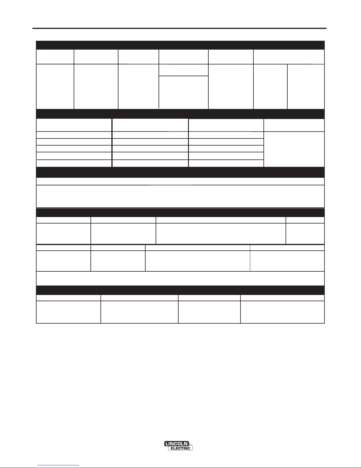
VANTAGE® 400 (AU)
(1)
Output rating in watts is equivalent to volt-amperes at unity power factor. Output voltage is within ± 10% at all loads up to rated capacity.
When welding, available auxiliary power will be reduced.
(2)
Reduced to less than 30V when VRD (VOLTAGE REDUCTION DEVICE) is on.
(3)
Maximum per circuit breaker rating.
(4)
To Top of enclosure. Add 7.35 (186.7mm) to top of exhaust. Add 3.87”(98.3mm) to top of Lift Bail.
A-1
INSTALLATION
A-1
TECHNICAL SPECIFICATIONS - VANTAGE® 400 (AU) (K32038-1)
M
ake/Model Description Speed (RPM) Displacement Starting Capacities
C
ode No. cu. in. (ltrs.) System
4 cylinder 135.6(2.2)
12VDC Battery
27.6 HP High Idle 1565
&
starter
Oil:
1500 RPM
Bore x Stroke
(Group 34; 650
8.45Qts. (8.0L)
Fuel: 20 gal.
naturally aspirated
Full Load 1500 cold crank amps) (75.7 L)
water cooled
3.43” X 3.64”
65 Amp Alternator
Radiator Coolant:
Diesel Engine Low Idle 1200 (87.1mm x 92.5mm) W / Built in Regulator
8.0Qts. (7.6L)
INPUT - DIESEL ENGINE
RATED OUTPUT @ 104° F (40° C) - WELDER
LUBRICATION EMISSIONS FUEL SYSTEM GOVERNOR
Full Pressure Mechanical Fuel Pump, Auto air bleed Mechanical
with Full Flow Filter EPA Tier IV Interim system, Electric shutoff solenoid, Indirect fuel injector.
AIR CLEANER ENGINE IDLER MUFFLER ENGINE PROTECTION
Low noise Muffler: Shutdown on low oil
Single Element Automatic Idler Top outlet can be rotated. pressure & high engine
Made from long life, aluminized steel. coolant temperature
ENGINE WARRANTY: 2 years / 2000 hours, all non-electric components, 3 years major non-electric
components . See Perkins warranty for details.
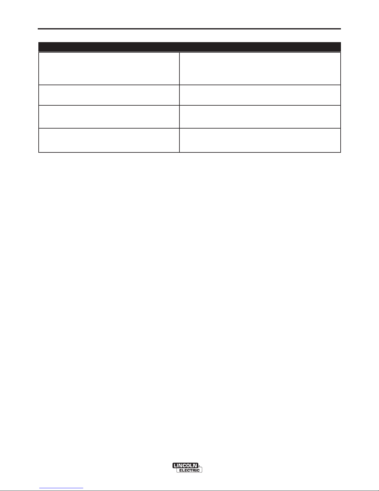
Welding Process
DC Constant Current
DC Pipe Current
Touch-Start™TIG
DC Constant Voltage
Arc Gouging
Output Range
30 TO 400 AMPS
40 TO 300 AMPS
20 TO 250 AMPS
14 TO 34 VOLTS
90 TO 400 AMPS
Max. Weld OCV
@Rated Load RPM
60 Volts
(2)
Welding Output
Current/Voltage/Duty Cycle
350A / 34V / 100%
300A / 32V / 100%
250A / 20V / 100%
350A / 34V / 100%
350A / 34V / 100%
Auxiliary Power
(1)
14,000 Watts Peak / 13,200 Watts Continuous, 50 Hz 400 Volts 3-Phase
6,900 Watts Peak
(3)
/ 6,900 Watts Continuous, 50 Hz 230 Volts 1-Phase
Sound Levels (Sound power: 96 dB Lwa)
ENGINE
RATED OUTPUT @ 40° C (104° F).- GENERATOR
Perkins 404D-22
HEIGHT WIDTH DEPTH WEIGHT
35.94
(4)
in. 27.00 in 60.00 in.
913 mm 686 mm 1524 mm
PHYSICAL DIMENSIONS
1230 lbs. (559kg.)
A-2
INSTALLATION
VANTAGE® 400 (AU)
A-2
(5)
Center-Tapped to ground.
MACHINE SPECIFICATIONS
R
eceptacles
Residual Current Device (RCD)
Circuit Breakers (Thermal/Magnetic)
Other Circuit Breakers
4
00V (3 Ph) x 1
230V (1 Ph) x 2
14 Pin Connector
6 Pin Connector
4-pole, 40Amp
(
30mA trip current)
3 Phase, 20 Amp x 1
1 phase, 15 Amp x 2
10A for Engine Battery Charging Circuit
10A for Wire Feeder Power
A-3
INSTALLATION
VANTAGE® 400 (AU)
A-3
SAFETY PRECAUTIONS
Only qualified personnel should install,
use, or service this equipment.
Do not attempt to use this equipment until you
have thoroughly read the engine manufacturer’s
m
anual supplied with your welder. It includes
important safety precautions, detailed engine
starting, operating and maintenance instructions,
and parts lists.
------------------------------------------------------------------------
ELECTRIC SHOCK can kill.
• Do not touch electrically live parts or
electrode with skin or wet clothing.
• Insulate yourself from work and
ground
• Always wear dry insulating gloves.
------------------------------------------------------------------------
ENGINEEXHAUSTcan kill.
• Use in open, well ventilated areas or
vent exhaust outside.
------------------------------------------------------------------------
MOVING PARTScan injure.
• Do not operate with doors open or
guards off.
• Stop engine before servicing.
• Keep away from moving parts.
------------------------------------------------------------------------
See additional warning information at
front of this operator’s manual.
WARNING
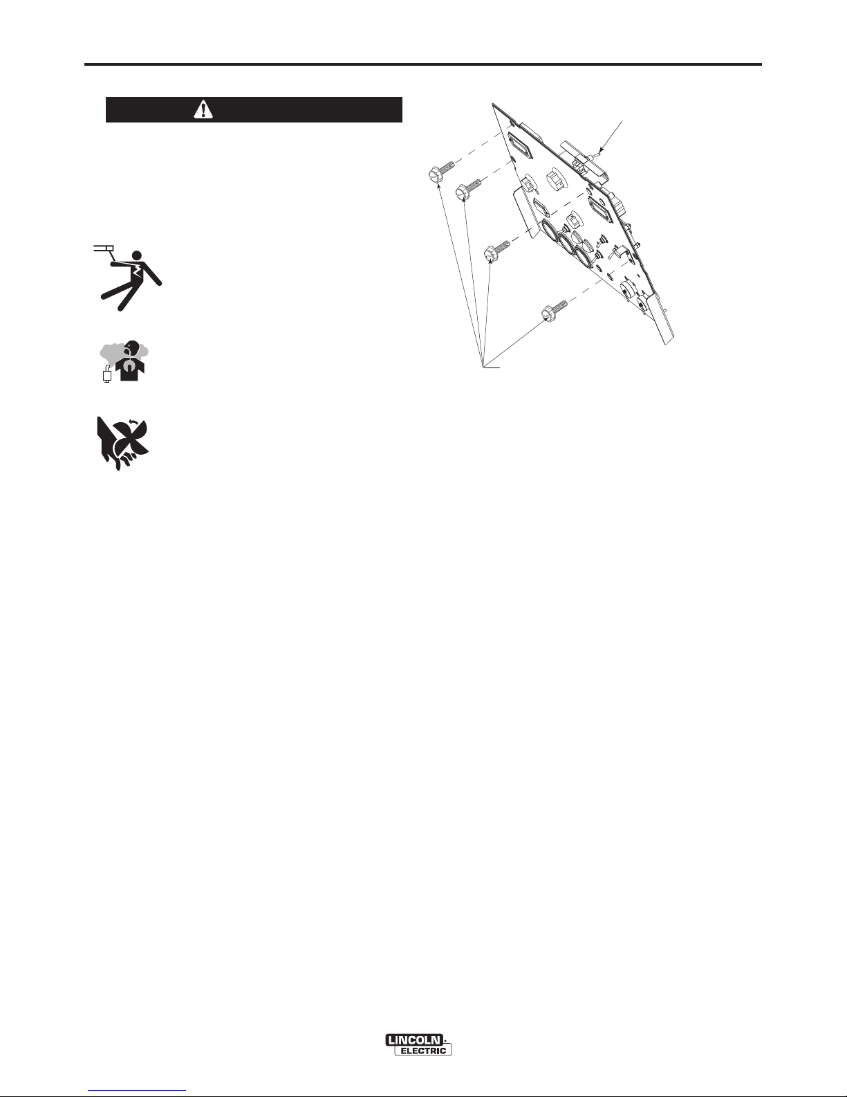
VRD (VOLTAGE REDUCTION DEVICE)
The VRD reduces the OCV (Open Circuit Voltage) at the
welding output terminals while not welding to less than 30V
DC when the resistance of the output circuit is above 200Ω
(ohms).
This feature provides additional safety in environments
with a higher risk of electric shock such as wet areas and
hot humid sweaty conditions.
When VRD is “On” the DOWNHILL PIPE mode is not
available.
The VRD requires that the welding cable connections be
kept in good electrical condition because poor connections
will contribute to poor starting. Having good electrical connections also limits the possibility of other safety issues
such as heat-generated damage, burns and fires.
The machine is shipped with the VRD switch in the “On”
position. To turn it “On” or “Off”.
• Turn the engine “Off”.
• Disconnect the negative battery cable.
• Lower the control panel by removing 4 front
panel screws.
(See Figure A.1)
• Place the VRD switch in the “On” or “Off” position.
(See Figure A.1)
LOCATION AND VENTILATION
The welder should be located to provide an unrestricted flow of clean, cool air to the cooling air inlets and to
avoid restricting the cooling air outlets. Also, locate
the welder so that the engine exhaust fumes are properly vented to an outside area.
STACKING
VANTAGE® 400 (AU) machines cannot be stacked.
ANGLE OF OPERATION
Engines are designed to run in the level condition
which is where the optimum performance is achieved.
The maximum angle of continuous operation is 25
degrees in all directions, 35 degrees Intermittent (less
than 10 minutes continuous) in all directions. If the
engine is to be operated at an angle, provisions must
be made for checking and maintaining the oil level at
the normal (FULL) oil capacity in the crankcase.
When operating the welder at an angle, the effective
fuel capacity will be slightly less than the amount
specified.
LIFTING
The VANTAGE® 400 (AU) weighs approximately
1383 lbs. (627kg.) with a full tank of fuel, 1230 lbs.
(559kg.) less fuel. A lift bail is mounted to the machine
and should always be used when lifting the machine.
(
VRD)-VOLTAGE REDUCTION DEVICE
S
WITCH IS LOCATED IN THIS AREA.
REMOVE 4 FRONT PANEL
SCREWS TO ACCESS
(
VRD) SWITCH
FIGURE A.1

A-4
INSTALLATION
VANTAGE® 400 (AU)
A-4
HIGH ALTITUDE OPERATION
At higher altitudes, output derating may be necessary. For
maximum rating, derate the machine 2.5% to 3.5% for every
1000 ft. (305 m). Due to new EPA and other local emissions
regulations, modifications to the engine for high altitude are
restricted within the United States. For use above 6000
ft.(1828 m) an authorized Perkins engine field service shop
should be contacted to determine if any adjustments can be
made for operation in higher elevations.
HIGH TEMPERATURE OPERATION
At temperatures above 104°F(40°C), Welder output derating
is necessary. For maximum output ratings, derate the
wel d er ou t put 2 volt s for e very 18°F( 1 0°C) a bove
104°F(40°C).
Cold weather starting:
With a fully charged battery and the proper oil, the
engine should start satisfactorily down to -15°F(26C°). If the engine must be frequently started at or
below 0°F (-18°C), it may be desirable to install coldstarting aides. The use of No. 1D diesel fuel is recommended in place of No. 2D at temperatures below
23°F (-5°C). Allow the engine to warm up before
applying a load or switching to high idle.
Note: Extreme cold weather starting may require
longer glow plug operation.
Under no conditions should ether or other starting
fluids be used with this engine!
------------------------------------------------------------------------
TOWING
Use a recommended trailer for use with this equipment for road, in-plant and yard towing by a vehicle(1). If the user adapts a non-Lincoln trailer, he must
assume responsibility that the method of attachment
and usage does not result in a safety hazard or damage the welding equipment. Some of the factors to be
considered are as follows:
1. Design capacity of trailer vs. weight of Lincoln
e
quipment and likely additional attachments.
2. Proper support of, and attachment to, the base of
the welding equipment so there will be no undue
stress to the framework.
3. Proper placement of the equipment on the trailer to
insure stability side to side and front to back when
being moved and when standing by itself while
b
eing operated or serviced.
4. Typical conditions of use, i.e., travel speed; roughness of surface on which the trailer will be operated; environmental conditions; like maintenance.
5. Conformance with federal, state and local laws.
(1)
(1) Consult applicable federal, state and local laws regarding spe-
WARNING
• Lift only with equipment of adequate lifting capacity.
• Be sure machine is stable when lifting.
• Do not lift this machine using lift
bail if it is equipped with a heavy
accessory such as trailer or gas
cylinder.
F
ALLING • Do not lift machine if lift bail is
EQUIPMENT can damaged.
cause injury. • Do not operate machine while
suspended from lift bail.
------------------------------------------------------------------------
VEHICLE MOUNTING
Improperly mounted concentrated loads may
cause unstable vehicle handling and tires or other
components to fail.
• Only transport this Equipment on serviceable
vehicles which are rated and designed for such
loads.
• Distribute, balance and secure loads so vehicle
is stable under conditions of use.
• Do not exceed maximum rated loads for components such as suspension, axles and tires.
• Mount equipment base to metal bed or frame of
vehicle.
• Follow vehicle manufacturer’s instructions.
------------------------------------------------------------------------
WARNING
PRE-OPERATION ENGINE SERVICE
READ the engine operating and maintenance instructions supplied with this machine.
• Stop engine and allow to cool before fueling
• Do not smoke when fueling.
• Fill fuel tank at a moderate rate and do not overfill.
• Wipe up spilled fuel and allow fumes to clear
before starting engine.
• Keep sparks and flame away from tank.
------------------------------------------------------------------------
WARNING
WARNING
OIL
The VANTAGE® 400 (AU) is shipped with the engine crankcase
f
illed with high quality SAE 10W-30 Oil that meets classification CG4 or CH-4 for diesel engines. Check the oil level before starting the
engine. If it is not up to the full mark on the dip stick, add oil as
required. Check the oil level every four hours of running time during
the first 50 running hours. Refer to the engine Operator’s Manual for
specific oil recommendations and break-in information. The oil
c
hange interval is dependent on the quality of the oil and the oper-
ating environment. Refer to the Engine Operator’s Manual for more
details on the proper service and maintenance intervals.
FUEL
DIESEL FUEL ONLY-Low sulphur fuel or ultra low sulphur
fuel in U.S.A. and Canada.
• Fill the fuel tank with clean, fresh fuel. The capacity of the
tank is 20 gals.(75.7 ltrs). When the fuel gauge reads empty
the tank contains approximately 2 gals. (7.6 ltrs.) of reserve
fuel.
NOTE: A fuel shut off valve is located on the pre-filter/sedi-
ment filter. Which should be in the closed position
when the welder is not used for extended periods of
time.
------------------------------------------------------------------------
ENGINE COOLING SYSTEM
Air to cool the engine is drawn in the side and exhausted
through radiator & case back. It is important that the intake and
exhaust air is not restricted. Allow a minimum clearance of 12
in. (305 mm) from the case back and 16 in.(406 mm) from either
side of the base to a vertical surface.
------------------------------------------------------------------------
BATTERY CONNECTION
Use caution as the electrolyte is a strong acid that can burn
skin and damage eyes.
------------------------------------------------------------------------
The VANTAGE® 400 (AU) is shipped with the negative battery
cable disconnected. Make certain that the RUN-STOP switch is in
the STOP position. Remove the two screws from the battery tray
using a screwdriver or a 3/8" socket. Attach the negative battery
cable to the negative battery terminal and tighten using a 1/2" socket or wrench.
NOTE: This machine is furnished with a wet charged battery; if
unused for several months, the battery may require a booster
charge. Be careful to charge the battery with the correct polarity.
(See Battery in “Maintenance Section”)
A-5
INSTALLATION
VANTAGE® 400 (AU)
A-5
cific requirements for use on public high
ways.
MUFFLER OUTLET PIPE
Using the clamp provided secure the outlet pipe to the outlet tube
with the pipe positioned such that it will direct the exhaust in the
desired direction. Tighten using a 9/16"(14mm) socket or wrench.
SPARK ARRESTER
Some federal, state or local laws may require that gasoline or diesel
engines be equipped with exhaust spark arresters when they are
operated in certain locations where unarrested sparks may present
a fire hazard. The standard muffler included with this welder does
not qualify as a spark arrester. When required by local regulations,
a suitable spark arrester, such as the K903-1 must be installed and
properly maintained.
An incorrect spark arrestor may lead to damage to the engine
or adversely affect performance.
------------------------------------------------------------------------
REMOTE CONTROL
The VANTAGE® 400 (AU) is equipped with a 6-pin and a 14-pin
connector. The 6-pin connector is for connecting the K857 or K8571 Remote Control or for TIG welding, the K870 foot Amptrol or the
K963-3 hand Amptrol. When in the CC-STICK, ARC GOUGING or
CV-WIRE modes and when a remote control is connected to the 6pin Connector, the auto-sensing circuit automatically switches the
OUTPUT control from control at the welder to remote control.
When in the DOWNHILL PIPE mode and when REMOTE CONTROL is connected to the 6-Pin or 14-Pin Connector, the OUTPUT
CONTROL is used to set the maximum current range of the OUTPUT CONTROL of the REMOTE.
Example: When the OUTPUT CONTROL on the welder is set to
200 amps the current range on the REMOTE CONTROL will be 40200 amps rather than the full 40-300 amps. Any current range that
is less than the full range provides finer current resolution for more
fine tuning of the output.
When in TOUCH START TIG mode and when a Amptrol is connected to the 6-Pin Connector, the OUTPUT dial is used to set the maximum current range of the CURRENT CONTROL of the Amptrol.
The 14-pin connector is used to directly connect a wire feeder control cable. In the CV-WIRE mode, when the control cable is connected to the 14-pin c
onnector, the auto-sensing circuit
automatically makes the Output Control inactive and
the wire feeder voltage control active.
NOTE: When a wire feeder with a built in welding voltage control is connected to the 14-pin
connector, do not connect anything to the 6-pin
connector.
------------------------------------------------------------------------
WARNING
CAUTION
WARNING
WARNING
WARNING
 Loading...