

Lincoln Electric Torchmate 4400, Torchmate 4800 User Manual

USER GUIDE
December 12, 2019
Copyright 2019
Lincoln Electric Cutting Systems

Torchmate 4400/4800
Page ii

Page iiiUser Guide

Table of Contents
Unpacking Your New Machine ..........................................................................v
Technical Support | On-Site Service ................................................................vi
Statement of Warranty ....................................................................................vii
Statement of Warranty Cont. ........................................................................viii
Safety Information .............................................................................................. 1
Site Preparation ...................................................................................................5
Grounding Your Machine ................................................................................... 6
Power/Air/Water Requirements ....................................................................... 7
FlexCut 80 Plasma Controls & Settings .......................................................... 8
FlexCut 80 Plasma Controls & Settings .......................................................... 9
FlexCut 125 Plasma Controls & Settings ........................................................ 10
FlexCut 125 Plasma Controls & Settings ......................................................... 11
Powering Up the Torchmate 4x00 ................................................................. 12
Overview of the Visual Machine Designer .................................................... 13
Job Group ............................................................................................................ 14
View Screen ........................................................................................................16
Datum & Program Zero Group ........................................................................ 18
Jogging .................................................................................................................19
AVHC & Dashboard ........................................................................................... 20
Accessory Toggle ...............................................................................................22
Using the Shape Library in VMD ..................................................................... 23
Running a Job .....................................................................................................25
Cut Quality ..........................................................................................................27
Build Your Own Cut Chart ................................................................................28
Nesting ................................................................................................................29
Performing Your First Test Cut .......................................................................32
Maintenance ....................................................................................................... 33
Cut Quality .......................................................................................................... 37
Basic Troubleshooting ..................................................................................... 40
Torchmate 4400/4800
Page iv
Unpacking Your New Machine
Your new Torchmate® 4400 or 4800 CNC machine is delivered assembled, but you will need to remove the shipping
material and gantry locks before operation. Verify all items have been shipped without damage before you accept the
order from the shipping company. Notify Lincoln Electric® 775-673-2200 to report any shipping damages. Your machine
was fully tested at the factory and a cut metal sample can be found in the waterbed of the machine.
Qty. Description Part Number
1 Lincoln Electric 4400 Torchmate CNC Table with FlexCutTM 8o Plasma Unit LECS-080-4400-00
TM
1 Lincoln Electric 4400 Torchmate CNC Table with FlexCut
1 Lincoln Electric 4800 Torchmate CNC Table with FlexCut
1 Lincoln Electric 4800 Torchmate CNC Table with FlexCut
1 Touchscreen Monitor and Computer (installed)
1 Consumable Starter Package (LC100/LC125) BK12849-SK / K4302
TM-CAD/CAM and Security dongle preinstalled
Black/Silver Instructional Flash Drive
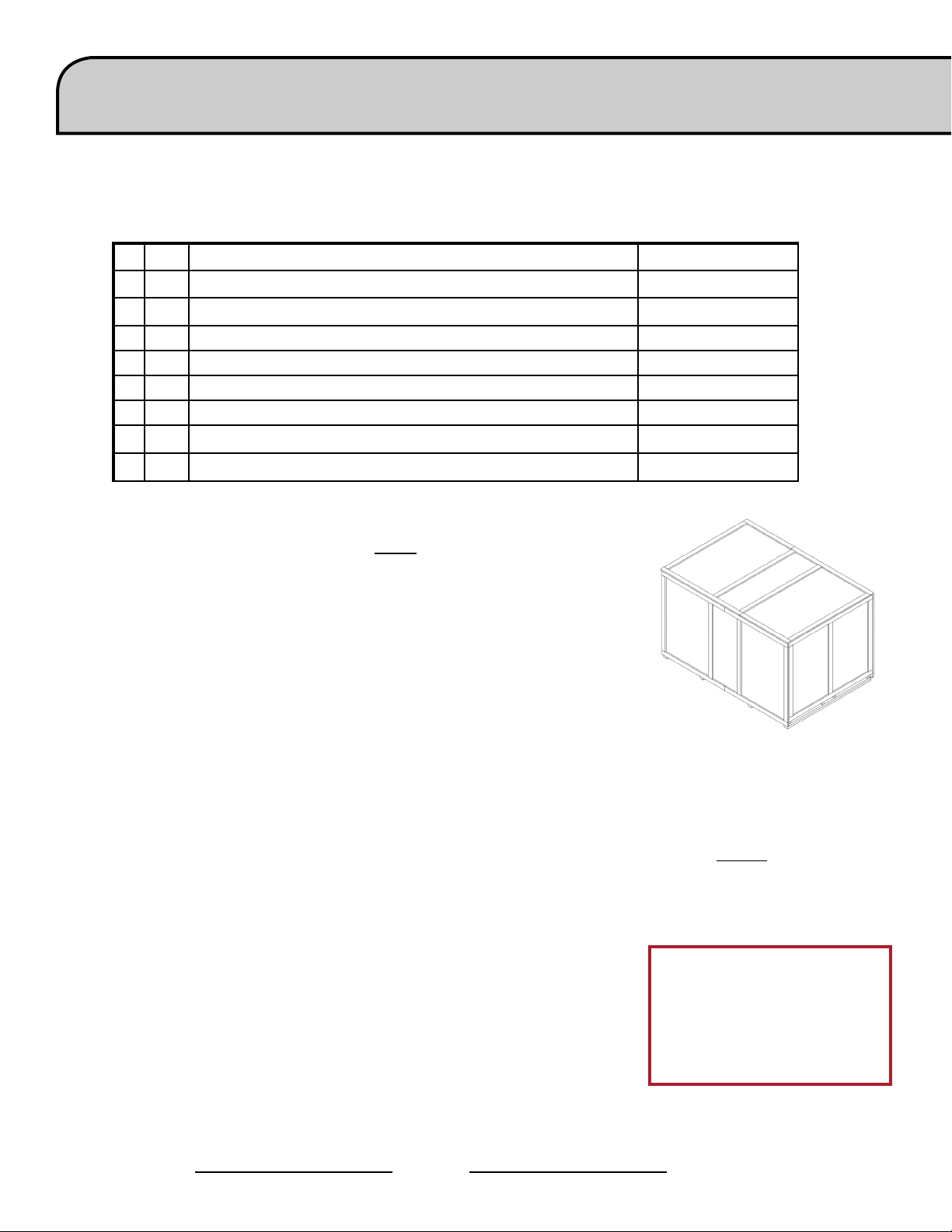
To uncrate your new Torchmate 4400/4800, pry the top of the crate o or remove
the ghost frame, remove the sides and set it aside. Remove the shrink wrap and
inspect the machine for damage. If damaged, do not accept the shipment!
125 Plasma Unit LECS-125-4400-00
TM
80 Plasma Unit LECS-080-4800-00
TM
125 Plasma Unit LECS-125-4800-00
Upon acceptance of the shipment, cut the plastic straps holding the plasma power
supply to the crate. The plasma power supply weighs (75 lbs+) and requires a team
lift to move it. Set the plasma power supply aside until nal machine placement.
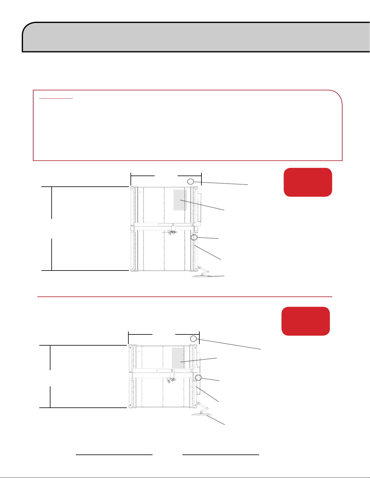
A forklift is required to place the machine in its operational position. Do not lift
the machine from the gantry or cable carrier side. Place forks in locations marked
“fork here” being careful not to hit the motion controller with the forks. Once the
machine is in position level the table using the adjustable feet.
Make sure the table does not rock.
Torchmate 4x00 models are shipped with a
factory installed gantry locks. The yellow locking
devices must be removed before the machine can
be made operational. DO NOT replace the bolts
after removing the yellow locking devices as this
will cause irreversible damage to the gantry.
Do Not Fork Lift From
Cable Carrier Side Of
Machine!
Page vUser Guide

Technical Support | On-Site Service
Lincoln Electric Cutting Systems provides a number of technical support opportunities with the purchase of
your new 4400 or 4800 Torchmate CNC cutting machine. The following is a brief outline of available options.
Onsite visits are available at an additional cost, call 775-673-2200 for additional information.
• Phone Support
Phone support is available Monday – Friday 7:00am-4:00pm Pacic Time.
Lincoln Electric will make every eort to handle phone calls in a timely manner,
but due to the nature of machine diagnoses and the varied capabilities of machine
operators, we cannot guarantee hold wait times for phone-in technical support.
Technical support includes machine assembly, troubleshooting, conguration,
and quality-related issues. Operational training is not included in phone technical
support.
• E-mail
Lincoln Electric will return e-mail to the support@Torchmate.com e-mail address
within 24 hours Monday-Friday.
• Webinars
Lincoln Electric provides live webinars from time to time to assist customers in the
optimization and operation of CNC systems. Please subscribe to our newsletter for
dates and times. http://torchmate.com/webinars
• Torchmate Training
Lincoln Electric provides a number of training opportunities at our Reno, Nevada
campus. Please call 775-673-2200 for details or visit http://torchmate.com/training
• Torchmate Academy
Torchmate Academy is a high denition, detailed video walkthrough covering every
aspect of your Torchmate table including setup, operation, detailed Torchmate CAD
videos, and maintenance. Call (775) 673-2200 or visit the website to learn more.
http://torchmate.com/academy
• Torchmate YouTube Channel:
Lincoln Electric provides a wide selection of how to tutorials on our YouTube page.
https://www.youtube.com/user/torchmatedotcom
• Torchmate Store
A variety of consumables, parts, and accessories can easily be purchased online
through the Torchmate store. Visit https://www.torchmatestore.com/ to learn
more.
Torchmate 4400/4800
Page vi

Statement of Warranty
30 Day Guarantee
Warranty
If Buyer is not satised with the performance of the Goods within 30 days from the
date the Goods were shipped from the Seller, Buyer may return the Goods in the
original carton(s) for a full refund less Shipping, Handling, Damages and Freight
Charges. All sales become nal after this 30 day period. Buyer should determine the
satisfactory performance of the Goods by using the software, and inspecting and
bench running the motors and/or accessory items. Any items to be returned for full
refund must be in new, unused (except for bench testing), and saleable condition at
the sole determination of the Seller. Items that, in the Seller’s judgment, have been
used or modied in any way, or kits that have been partially or fully completed will
be subject to a restocking fee to be determined by the Seller. A return merchandise
authorization number (RMA) must be obtained by the customer prior to any return.
Shipments of returned items not marked with a valid RMA will be refused.
Electronics and motors are warranted by their manufacturer to the original purchaser
for 24 months from the date of Torchmate, Inc.’s sale invoice. Mechanical components
are standard industrial parts and are not warranted except by their respective
manufacturers. If any of the warranted items are found by Seller to be defective, such
Goods will, at Seller’s option, be replaced or repaired at Seller’s cost. No defective
goods are to be returned without written authorization of seller. The sole purpose
of the stipulated exclusive remedy shall be to provide the Buyer with free repair and
replacement of defective Goods in the manner provided herein. This exclusive remedy
shall not be deemed to have failed of its essential purpose so long as the Seller is
willing and able to repair or replace defective Goods in the prescribed manner. The
foregoing warranty is in lieu of all other warranties, express or implied, including
those of merchantability or tness for any purpose not expressly set forth herein. No
armation of Seller, by words or action, other than as set forth in this Section shall
constitute a warranty. Seller’s warranty does not apply to any Goods which have been
subjected to misuse, mishandling, misapplication, neglect (including but not limited
to improper maintenance), accident, improper installation, modication (including
by not limited to use of unauthorized parts or attachments), or adjustment or repair
performed by anyone other than Seller or one of Seller’s authorized agents. When
returning products to Seller packaging must be adequate or all warranty is null and
void. Buyer will pay for the cost of Shipping to and from the Seller for all warranty
repairs.
Any claim by Buyer with reference to the Goods sold hereunder shall be deemed waived
by the Buyer unless submitted in writing to seller within the earlier of (i) thirty (30)
days following the date Buyer discovered or by reasonable inspection should have
discovered, any claimed breach of foregoing warranty, or (ii) 12 months following the
date of shipment. Any cause of action for breach of the foregoing warranty shall be
brought within one year from the date the alleged breach was discovered or should
have been discovered, whichever occurs rst.
Page viiUser Guide

Statement of Warranty Cont.
Seller’s liability (whether under the theories of breach of contract or warranty,
negligence, or strict liability) for its Goods shall be limited to repairing or replacing
Goods found by Seller to be defective, or at Seller’s option, to refunding the purchase
price of such Goods or parts thereof.
In no event shall seller be liable for consequential damages arising out of or in
connection with this agreement, including without limitation, breach of any obligation
imposed on seller hereunder. Consequential damages shall include without limitation,
loss of use, income or prot, or loss sustained as the result of injury (including death)
to any person, or loss of or damage to property (including without limitation property
handled or processed by the use of the goods). Buyer shall indemnify seller against all
liability, cost or expense which may be sustained by seller on account of any such loss,
damage, or injury.
Upon buyer’s receipt of shipment, Buyer shall immediately inspect the Goods. Unless
Buyer provides Seller with written notice of any claim for shortage, overcharge, or
damage of Goods within ten (10) days from invoice date, such Goods shall be deemed
nally inspected, checked and accepted by Buyer and no allowances shall be made
thereafter. In absence of shipping and packaging instructions, Seller shall use its own
discretion in the choice of carrier and method of packing. Seller shall not be responsible
for insuring shipments unless specically requested by Buyer and any insurance or
special packaging so requested shall be at Buyer’s expense and valuation.
Title to any Goods sold and risk of loss of such Goods passes to Buyer upon delivery by
Seller to carrier and any claims for losses or damages shall be made by Buyer directly
with carrier.
A. In addition to the rights and remedies conferred upon Seller by law, Seller shall not
be required to proceed with the performance of any order or contract if the Buyer
is in default in the performance of any order or contract with Seller, and in case
of doubt as to Buyer’s nancial responsibility, shipments under this order may be
suspended.
B. No delay or omission by Seller in exercising any right or remedy provided for herein
shall constitute a waiver of such right or remedy and shall not be constituted as a
bar to or a waiver of any such right or remedy on any future occasion.
C. The sale of Goods shall be governed by the laws of the State of Maryland. Seller
agrees to comply with all applicable laws of the United States.
D. The purchasers of products from Lincoln Electric Cutting Systems are responsible
to dispose of consumables, uids and machinery at the end of the life cycle in
accordance with federal and local regulations.
The invalidity or unenforceability of any one or more phrases, sentences, or sections
shall not aect the validity or enforceability of the remaining portions of this
Agreement.
Limitation of Liability
Disclaimer of Consequential
Damages
Acceptance and
Transportation
Title and Risk of Loss
General Conditions
Severability
Torchmate 4400/4800
Page viii

Safety Information
Torchmate and Lincoln Electric Cutting Systems equipment is designed and built with safety in mind. However, your overall
safety can be increased by proper installation and thoughtful operation.
WARNING: DO NOT INSTALL, OPERATE, OR REPAIR THIS EQUIPMENT WITHOUT READING THE SAFETY WARNINGS CONTAINED
THROUGHOUT THIS MANUAL.
Please Note:
PROTECT YOURSELF AND OTHERS FROM POSSIBLE SERIOUS INJURY OR DEATH
KEEP CHILDREN AWAY
IF YOU WEAR A PACEMAKER, YOU SHOULD CONSULT WITH YOUR DOCTOR BEFORE OPERATING
• Read and understand the following safety highlights. For additional safety information it is strongly recommended
that you purchase a copy of “Safety in Welding & Cutting - ANSI Standard Z49.1” from the American Welding Society,
P.O. Box 351040, Miami, Florida 33135 or CSA Standard W117.2.
BE SURE THAT ALL INSTALLATION, OPERATION, MAINTENANCE, AND REPAIR PROCEDURES ARE PERFORMED ONLY
BY QUALIFIED INDIVIDUALS
ELECTRIC SHOCK CAN KILL
• The electrode and work (or ground) circuits are electrically “hot” when the power source is on. Do not touch these “hot”
parts with your bare skin or wet clothing. Wear dry, hole-free gloves to insulate hands.
• Disconnect the power source before performing any service or repairs. When the power source is operating, voltages in
excess of 250 volts are produced. This creates the potential for serious electrical shock - possibly even fatal.
• Insulate yourself from work and ground using dry insulation. Wear dry gloves and clothing. Take extra care when the
work place is moist or damp.
• Always be sure the work cable makes a good electrical connection with the metal being cut or gouged. The connection
should be as close as possible to the area being cut or gouged.
• Ground the work or metal to be cut or gouged to a good electrical (earth) ground.
• Maintain the plasma torch, cable and work clamp in good, safe operating condition. Repair or replace all worn or damaged
parts. Replace damaged insulation.
• Never dip the torch in water for cooling or plasma cut or gouge in or under water.
• When working above oor level, protect yourself from a fall should you get a shock.
• Operate the pilot arc with caution. The pilot arc is capable of burning the operator, others or even piercing safety clothing.
ARC RAYS CAN BURN
• Plasma Arc Rays can injure your eyes and burn your skin.
The plasma arc process produces very bright ultraviolet and
infrared rays. These will damage your eyes and burn your skin
if you are not properly protected.
• Use safety glasses and a shield with the proper lter and cover
plates to protect your eyes from sparks and the rays of the arc
when performing or observing plasma arc cutting or gouging.
Glasses, head-shield, and lter lens should conform to ANSI
Z87. I standards.
• Use suitable clothing including gloves made from durable
ame-resistant material to protect your skin and that of your
helpers from the arc rays.
• Protect other nearby personnel with suitable non-ammable
screening and/or warn them not to watch the arc nor expose
themselves to the arc rays or to hot spatter or metal.
Page 1User Guide
Arc Current Minimum
Shade No.
Suggested
Shade No.
Less than 20A 4 4
20A-40A 5 5
40A-60A 6 6
60A-300A 8 9
300A-400A 9 12
400A-800A 10 14

FUMES AND GASES can be dangerous:
• Plasma cutting or gouging may produce fumes and gases hazardous to health. Avoid breathing these fumes and gases.
When cutting or gouging, keep your head out of the fumes. Use enough ventilation and/or exhaust at the arc to keep
fumes and gases away from the breathing zone.
• Use an air-supplied respirator if ventilation is not adequate to remove all fumes and gases.
• When plasma cutting or gouging on lead or cadmium plated steel and other metals or coatings which produce highly
toxic fumes, keep exposure as low as possible and within applicable OSHA PEL and ACGIH TLV limits using local exhaust or
mechanical ventilation. In conned spaces or in some circumstances, outdoors, a respirator may be required.
• Additional precautions are also required when cutting (zinc) galvanized steel or materials containing or coated with any of
the following:
Antimony Beryllium Cobalt Manganese Selenium
Arsenic Cadmium Copper Mercury Silver
Barium Chromium Lead Nickel Vanadium
• The operation of plasma cutting or gouging fume control equipment is aected by various factors including proper use
and positioning of the equipment, maintenance of the equipment, and the specic procedure and application involved.
Worker exposure levels should be checked upon installation and periodically thereafter to be certain levels are within
applicable OSHA PEL and ACGIH TLV limits. For information on how to test for fumes and gases in your work place, refer to
publications section of this manual.
• Do not use plasma cutting or gouging equipment in locations near chlorinated hydrocarbon vapors coming from
degreasing, cleaning or spraying operations. The heat and rays of the arc can react with solvent vapors to form phosgene,
a highly toxic gas, and other irritating products. Remove all sources of these vapors.
• Gases used for plasma cutting and gouging can displace air and cause injury or death. Always use enough ventilation,
especially in conned areas, to insure breathing air is safe.
• Read and understand the manufacturer’s instructions for this equipment and follow your employer’s safety practices.
• This product, when used for cutting, produces fumes or gases which contain chemicals known to the State of California to
cause birth defects
• Some dust created by routing, sawing, grinding, drilling, and other construction activities contains chemicals known to
cause cancer, birth defects or other reproductive harm. Avoid prolonged contact with this dust. Wear protective clothing
and wash exposed areas with soap and water. Allowing dust to get into your mouth, eyes, or lay on the skin may promote
absorption of harmful chemicals.
Some examples of these chemicals are:
• Lead from lead-based paint.
• Crystalline silica from bricks and cement and other masonry products.
• Arsenic and chromium from chemically-treated lumber (CCA).
Your risk from these exposures varies, depending on how often you do this type of work. To reduce your exposure to these
chemicals: work in a well ventilated area, and work with approved safety equipment, such as those dust masks that are
specially designed to lter out microscopic particles.
FOR ELECTRICALLY powered equipment:
• Turn o input power using the disconnect switch at the fuse box before working on the equipment.
• Install equipment in accordance with the U.S. National Electrical Code, all local codes and the manufacturer’s
recommendations.
• Ground the equipment in accordance with the U.S. National Electrical Code and the manufacturer’s recommendations.
Torchmate 4400/4800
Page 2

Cutting ame and sparks can cause FIRE OR EXPLOSION:
• Fire and explosion can be caused by hot slag, sparks, oxygen fueled cutting ame, or the plasma arc.
• Have a re extinguisher readily available. Provide a re watch when working in an area where re hazards may exist.
• When not cutting or gouging, make certain no part of the electrode circuit is touching the work or ground. Accidental contact
can cause overheating and create a re hazard.
• Be sure there are no combustible or ammable materials in the workplace. Any material that cannot be removed must be
protected.
• Sparks and hot materials from cutting or gouging can easily go through small cracks and openings to adjacent areas.
• Avoid cutting or gouging near hydraulic lines.
• Do not cut or gouge tanks, drums or containers until the proper steps have been taken to insure that such procedures will not
cause ammable or toxic vapors from substances inside. They can cause an explosion even though they have been “cleaned.”
For information purchase “Recommended Safe Practices for the Preparation for Welding and Cutting of Containers and Piping
That Have Held Hazardous Substances”, AWS F4.1 from the American Welding Society (see address above).
• Vent hollow castings or containers before heating, cutting or gouging. They may explode.
• Do not add fuel to engine driven equipment near an area where plasma cutting or gouging is being done.
• Connect the work cable to the work as close to the cutting or gouging area as practical. Work cables connected to the building
framework or other locations away from the cutting or gouging area increase the possibility of the current passing through
lifting chains, crane cables or other alternate circuits. This can create re hazards or overheat lifting chains or cables until they
fail.
• Hydrogen gas may be formed and trapped under aluminum work pieces when they are cut underwater or while using a water
table. DO NOT cut aluminum alloys underwater or on a water table unless the hydrogen gas can be eliminated or dissipated.
Trapped hydrogen gas that is ignited will cause an explosion.
• Read and follow NFPA 51B “ Standard for Prevention During Welding, Cutting and Other Hot Work”, available from NFPA, 1
Batterymarch Park, PO box 9101, Quincy, Ma 022690-9101.
Laser Safety Facts:
• This is a class 3R laser product. Handle with caution.
• This product contains a diode laser. Make sure to follow all safety precautions when operating.
• DO NOT look into the direct or reected beam. This can cause eye injury up to 110 ft. (34 m) away.
• NEVER point any laser towards aircraft or vehicles; it is unsafe and illegal. The laser can cause visual interference with
pilots and drivers, and interferes with vision up to 2,400 ft (730 m) away. The laser can be a distraction up to 4.5 miles
(7.3 km) away.
• Class 3R lasers are safe when handled carefully. DO NOT look into the beam. Avoid accidental exposure to eyes.
• Do not aim at aircraft.
• This is not a toy. Always supervise children.
For more information on laser safety please visit:
LaserSafety.info/3R
or scan the QR code below.
Page 3User Guide

CYLINDER may EXPLODE if damaged:
• Use only compressed gas cylinders containing the correct gas for the process used and properly operating regulators
designed for the gas and pressure used. All hoses, ttings, etc. should be suitable for the application and maintained in
good condition.
• Always keep cylinders in an upright position securely chained to an undercarriage or xed support.
• Cylinders should be located: • Away from areas where they may be struck or subjected to physical damage.
• A safe distance from plasma cutting or gouging, arc welding operations and any other source of heat, sparks, or ame.
• Never allow any part of the electrode, torch or any other electrically “hot” parts to touch a cylinder.
• Keep your head and face away from the cylinder valve outlet when opening the cylinder valve.
• Valve protection caps should always be in place and hand tight except when the cylinder is in use or connected for use.
Read and follow the instructions on compressed gas cylinders, associated equipment, and CGA publication P-l, “Precautions
for Safe Handling of Compressed Gases in Cylinders,”available from the Compressed Gas Association 1235 Jeerson Davis
Highway, Arlington, VA 22202.
PLASMA ARC can injure:
• Keep your body away from nozzle and plasma arc.
• Operate the pilot arc with caution. The pilot arc is capable of burning the operator, others or even piercing safety clothing.
ELECTRIC AND MAGNETIC FIELDS may be dangerous:
• Electric current owing through any conductor causes localized Electric and Magnetic Fields (EMF). Cutting or gouging
current creates EMF elds around torch cables and cutting machines.
• EMF elds may interfere with some pacemakers, so operators having a pacemaker should consult their physician before
cutting or gouging.
• Exposure to EMF elds during cutting or gouging may have other health eects which are now not known.
• All operators should use the following procedures in order to minimize exposure to EMF elds from the cutting or gouging
circuit:
• Route the torch and work cables together - Secure them with tape when possible.
• Never coil the torch cable around your body.
• Do not place your body between the torch and work cables. If the torch cable is on your right side, the work cable should
also be on your right side.
• Connect the work cable to the workpiece as close as possible to the area being cut or gouged.
• Do not work next to cutting power source.
For more information on electromagnetic interference please visit:
http://torchmate.com/white-papers/EMI-Reduction
While Operating the machine:
• WEAR CORRECT EYE, EAR & BODY PROTECTION
• PROTECT your eyes and face with welding helmet properly tted and with proper grade of lter plate
(See ANSI Z49.1).
• PROTECT your body from welding spatter and arc ash with protective clothing including woolen clothing,
ame-proof apron and gloves, leather leggings, and high boots.
• PROTECT others from splatter, ash, and glare with protective screens or barriers.
• IN SOME AREAS, protection from noise may be appropriate.
• BE SURE protective equipment is in good condition.
• Provide adequate light to the area of the machine.
• Also, wear safety glasses in work area AT ALL TIMES.
• Do not climb on machine. It is not intended as a ladder or to support anything but the intended use of metal
cutting. By climbing onto the machine, could cause falling that can result in injury or death.
Torchmate 4400/4800
Page 4
Site Preparation
When installing a Lincoln Electric CNC Cutting System in your shop, there are many factors that will inuence the
potential productivity, ease of use of the machine and the safety of the operator. The main factors to prepare for
include: the physical layout and placement of the machine in the shop, the availability of power, an EMI ground,
compressed air and other gasses, and ventilation.
Please Note:
When preparing to install the Lincoln Electric CNC Cutting System, provide sucient space. Three feet of
work space (914 mm) should be obstacle free around the machine.
• Forklift load material opposite the cable carrier only. Utilize the back of the machine to park the gantry
while loading material.
• A dedicated earth ground must be provided and should be installed in a manner to reduce trip hazard.
• The power lead included is limited to 10 feet.
114”
(2.9 m)
67”
(1.7 m)
Load From
Side
This
TORCHMATE
4800
Load From
Side
This
74”
(1.88 m)
MAINTAIN WORK
74”
(1.88 m)
AREA
Power Supply
Plasma
Machine
Under Table
Earth
Ground
Provided by Other
Motion
Control
Under Table
Operator
Console
Plasma
Machine
Under Table
Earth Ground
Provided by Other
Air Supply
Provided by Other
Power Supply
Air Supply
Provided by Other
4800
4400
TORCHMATE
4400
MAINTAIN WORK
Page 5User Guide
AREA
Motion
Control
Under Table
Operator
Console

Grounding Your Machine
Proper grounding must be provided to ensure personnel safety and to suppress high frequency noise. The
foundation of good grounding is an eective earth ground rod. A start ground point connects to the rod with a
short, heavy conductor. A simply copper clad steel rod can be driven into the ground to create a Grounding Rod.
A ground rod must be installed. Consult with a qualied electrical technician to verify your system grounding.
Please Note:
Use 6 AWG Stranded Wire to connect the Star Ground on the table to the customer supplied dedicated
earth ground.
• For proper operation of your CNC cutting tables you are required to run a 6 AWG cable from the “star”
ground to a dedicated earth-ground rod.
• Ground Rod installations are covered by NEC Section 250.
• The Earth Ground is not included with the machine.
Step 1:
Step 2:
Place the plasma unit into
the appropriate location.
Re-install the power lead
and the table ground into the
front of the machine.
The FlexCut plasma unit
is shipped with a factory
ground attached to the star
ground. In addition, a work
ground is attached to the
star ground to connect to
your material to be cut.
If the work piece is painted
or dirty, it may be necessary
to expose the bare metal
to make a good electrical
connection.
Torchmate 4400/4800
Page 6

Power/Air/Water Requirements
Please refer to the FlexCut operators manual for complete installation and operation guidelines. Only a qualied
electrician should connect the input leads to the Torchmate 4400/4800 CNC unit and FlexCut Plasma unit.
Connections should be made in accordance with all local and national electrical codes. Failure to do so may result in
bodily injury or death.
The FlexCut 80 is rated for 208 VAC through 575 VAC input voltages, single or three phase and 50 or 60 Hz. The
FlexCut 125 is rated for 380 VAC through 575 VAC input voltage, three phase only and 50 or 60 Hz. Before connecting
the machine to power, be sure the input supply voltage, phase and frequency all match those listed on the machine
rating plate.
The FlexCut 80 automatically senses and adjusts to work with any input voltage, phase or frequency listed on the
rating plate. No reconnect switch settings are required. The power supply cord is supplied without an attachment
plug to accommodate single phase or three phase installations.
Warning:
The FlexCut on/o switch
is not intended as a service
disconnect for this equipment.
Only a qualied electrician
should connect the input leads
to the Torchmate 4400-4800.
The Torchmate 4400-4800 CNC machine requires clean, dry, oil-free compressed air or nitrogen. A high pressure
regulator MUST be used with a compressor or high pressure cylinder.
Supply pressure must be between 87-110 psi (6-7.6 bar) with ow rated rates of at least 300 SCFH or 140 SLPM.
AIR SUPPLY PRESSURE SHOULD NEVER EXCEED 110 PSI OR DAMAGE TO THE MACHINE MAY OCCUR!
A standard nominal 5 micron in-line lter is recommended, but for optimal performance, select a pre-lter with
a 3 micron absolute rating. Air must be supplied to the plasma with 3/8” inside diameter tubing and 1/4 NPT quick
disconnect coupler. Air lines should be run as to not create a trip hazard.
Water should be installed in the table pan before operation. Rust inhibitors such as non sodium nitrite based
products may be used as a corrosion inhibitor in CNC plasma water tables. Operators are encouraged to use a
readily available product designed for use in CNC plasma tables.
Water Capacity
• 4400 models hold approximately 60 gals or 230 liters.
• 4800 models hold approximately 107 gals or 405 liters.
Page 7User Guide

FlexCut 80 Plasma Controls & Settings
Please refer to the complete operation and user manual for your FlexCut 80 located with the plasma unit.
When the Machine is turned on, and auto-test is executed, all of the LEDs on the Control Panel will light up.
4
Controls »
FRONT
1. CUTTING OPERATING MODE SELECTION
2. PRIMARY AIR, GAS PRESSURE GAUGE
AND REGULATOR KNOB
3. TORCH CONNECTION
4. SINGLE PHASE GREEN LED
5. POWER ONOFF GREEN LED
6. OUTPUT RED LED
7. THERMAL YELLOW LED
8. GAS PRESSURE YELLOW LED
9. PARTSINPLACE PIP YELLOW LED
10. OUTPUT CURRENT KNOB
11. CNC INTERFACE
12. WORK GROUND
5
6
1
2
3
7
8
9
10
11
12
BACK
13. INPUT CORD 10 ft. 3.0 M
14. POWER SWITCH
15. AIR OR GAS INLET
14 in. NPT QUICK CONNECT
16. FAN
Torchmate 4400/4800
14
13
15
16
Page 8

FlexCut 80 Plasma Controls & Settings
Please refer to the FlexCut operators manual for complete installation and operation guidelines.
Do not overtighten the consumables. Only tighten until the parts are seated properly.
Product
Name
FlexCut
Product
Number
80 K4809-1 200-208/230/380/
Input Power
Voltage/Phase/Hertz
460/575/3/50/60
230/1/50/60 60A/140V/100%
200-208/1/50/60 60A/140V/100%
Rated Output:
Current/
Voltage/Duty Cycle
60A/140V/100% 3PH/100%
80A/140V/80% 3PH/80%
80A/140V/80%
80A/140V/60%
Input Current @
Rated Output
31/28/16/14/12
41/37/21/18/14
1PH/100%
48
1PH/80%
62
1PH/100%
52
1PH/60%
71
Output
Range
3PH
25-80A
1PH
25-80A
25-80A
MECHANIZED CUT CAPACITY - MATERIAL THICKNESS MILD STEEL
Recommended cut capacity at 24 ipm 3/4 in. (19 mm)
PIERCE CAPACITY - MATERIAL THICKNESS MILD STEEL
Pierce capacity with programmable torch height control
MAXIMUM CUT SPEEDS - MILD STEEL
1/4 in. (6.35 mm) 148 ipm
1/2 in. (12.7 mm) 52 ipm
3/4 in. (19 mm) 26 ipm
Gas Pressure
Required
87 to 109 PSI
(6.0-7.5 Bar)
3/4 in. (19 mm)
Gas Flow
Rate
380 SCFH @ 80 PSI
180 SLPM @ 5.5 Bar
H x W x D
in (mm)
17.9 x 11.8 x 25.4
(455 x 301 x 645)
Net Wt.
lb (kg)
96 (44)
CONSUMABLES STARTER KIT FOR LC100M MACHINE TORCH (BK12849-SK)
Electrode (LC100M) BK12849-3 5 Qty
Shield Cap 60A-80A (LC100M) BK12849-15 1 Qty
Nozzle 40A (LC100M) BK12849-4 1 Qty
Nozzle 60A (LC100M) BK12849-5 2 Qty
Nozzle 80A (LC100M) BK12849-6 2 Qty
Swirl Ring (LC100M) BK12849-9 1 Qty
Retaining Cap-CTP (LC100M) BK12849-22 1 Qty
Shield Cap-40A (LC100M) BK12849-14 1 Qty
Page 9User Guide
 Loading...