

Page 1
APPLICATION
WAVEFORM CONTROL TECHNOLOGY
TM
Tandem MIG
High-Speed and High-Deposition Welding
Low cost and profitability are key
business objectives, whether the
product offering is a wheel, a
water tank, or a truck frame. It
used to be thought that on the
road to lower cost, quality had to
be sacrificed. That’s no longer
true with Tandem MIG welding.
The following factors affect
pricing per welded part:
• Capital Equipment
• Overhead
• Labor cost
• Part production rates
Lincoln Tandem MIG welding
systems are designed to produce
quality welds at welding speeds
well above accepted single
wire processes. The unique
engineered output control of the
Tandem MIG dual wire process
is designed to overcome the
barriers limiting the travel speed
capabilities of conventional single
wire GMAW processes.
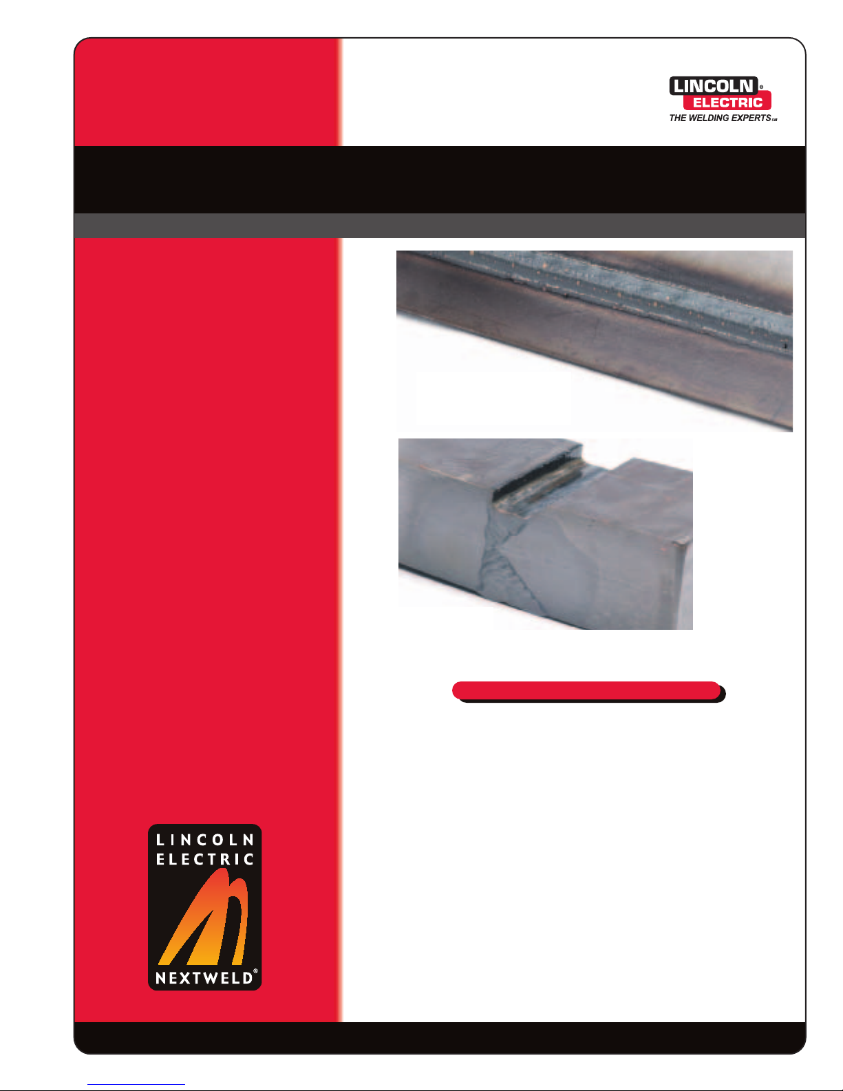
Increased deposition
on thicker materials
reduces welding time
and distortion.
TM
Fast travel speeds on thin
lap welds increase the
number of parts per day.
advantages
The future of welding is here.
INCREASED TRAVEL SPEEDS
• The combined contribution of two separate welding arcs in one weld pool
provides the control to overcome the lack of follow tendencies of single
arc processes.
INCREASED DEPOSITION
• Two small diameter Tandem MIG wire electrodes provide higher melt-off
rates per current drawn when compared to a single larger diameter wire
electrode at similar current draws.
IMPROVED THROUGHPUT
• Higher travel speeds and higher deposition rates reduce part welding
time cycles.
®
NX-3.70 10/05© Copyright 2005 The Lincoln Electric Company. All rights reserved.
Page 2
WAVEFORM CONTROL TECHNOLOGY
TM
APPLICATION
Tandem MIG
High-Speed and High-Deposition Welding
What Is It?
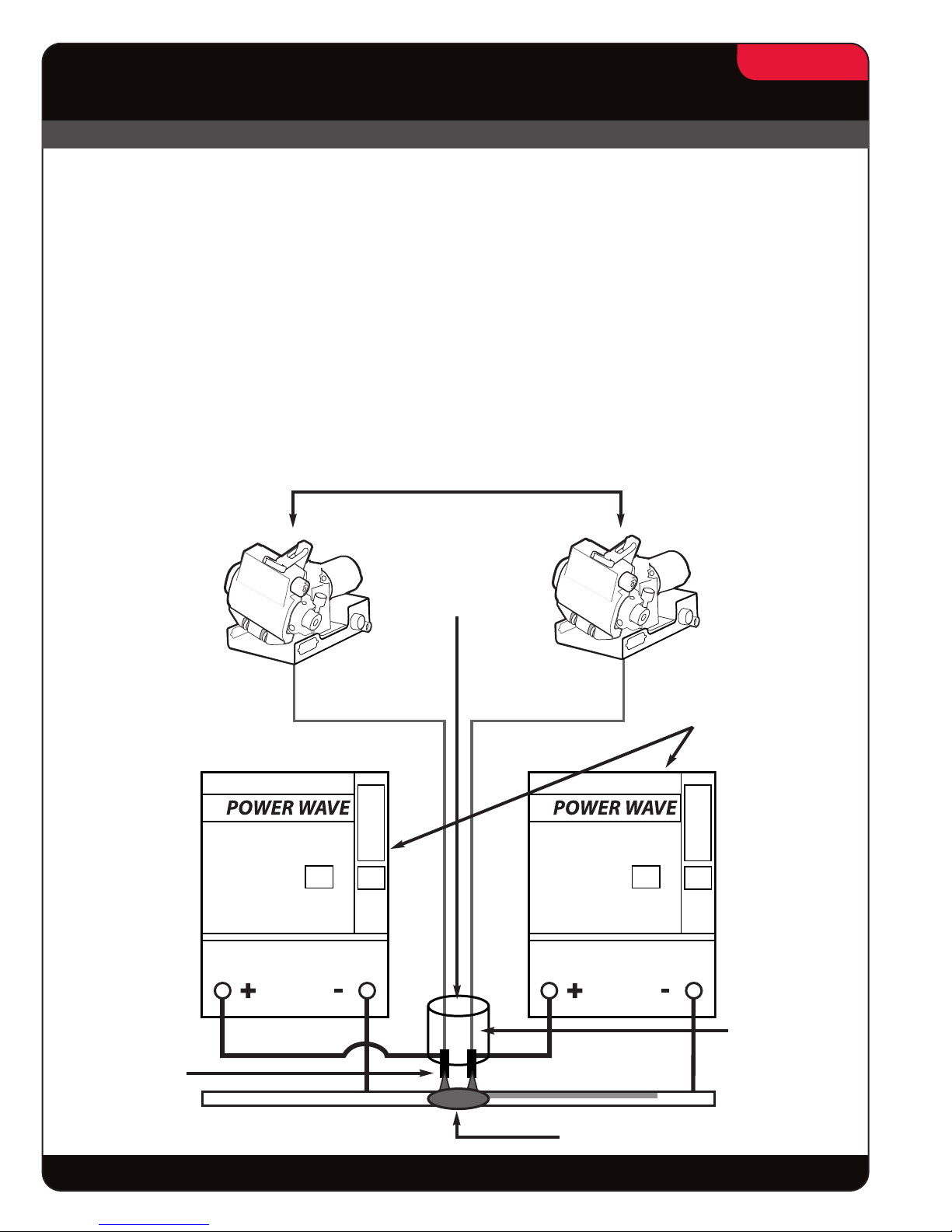
Tandem MIG is a dual wire GMAW process that is
used in automated welding applications to improve
welding productivity and part throughput. The process
utilizes two welding power sources and two wire
feeders acting in tandem to deliver two wire electrodes
through a single welding torch. The dual wire welding
torch, capable of often doubling the welding output of
a single wire torch, is used in hard automation and
robotic arc welding cells in the same manner as a
single wire welding torch would be. The two welding
arcs that are generated in the Tandem MIG process
are electrically isolated from one another and are
Tandem MIG Configuration
Two Wire Feeders
2/16
controlled independently. The welding arcs work
together, generally separated by less than 0.50 inches,
in the same weld pool. The independent control of the
two welding arcs is used to control the thermal and
fluid dynamics of the weld pool to further enhance
welding performance. The added deposit rate achieved
by the dual wire delivery and the added weld pool
control is used to overcome single wire limitations to
produce high travel speeds and electrode melt-off
rates (weld metal deposition). Special power source
welding software is used to allow the two welding arcs
to operate in unison.
Two Separate
Welding Arcs
Shielding Gas
Two
Power Sources
One
Welding Torch
The future of welding is here.
One Weld Pool
®
Page 3
WAVEFORM CONTROL TECHNOLOGY
TM
APPLICATION
Tandem MIG
High-Speed and High-Deposition Welding
How Does It Work?
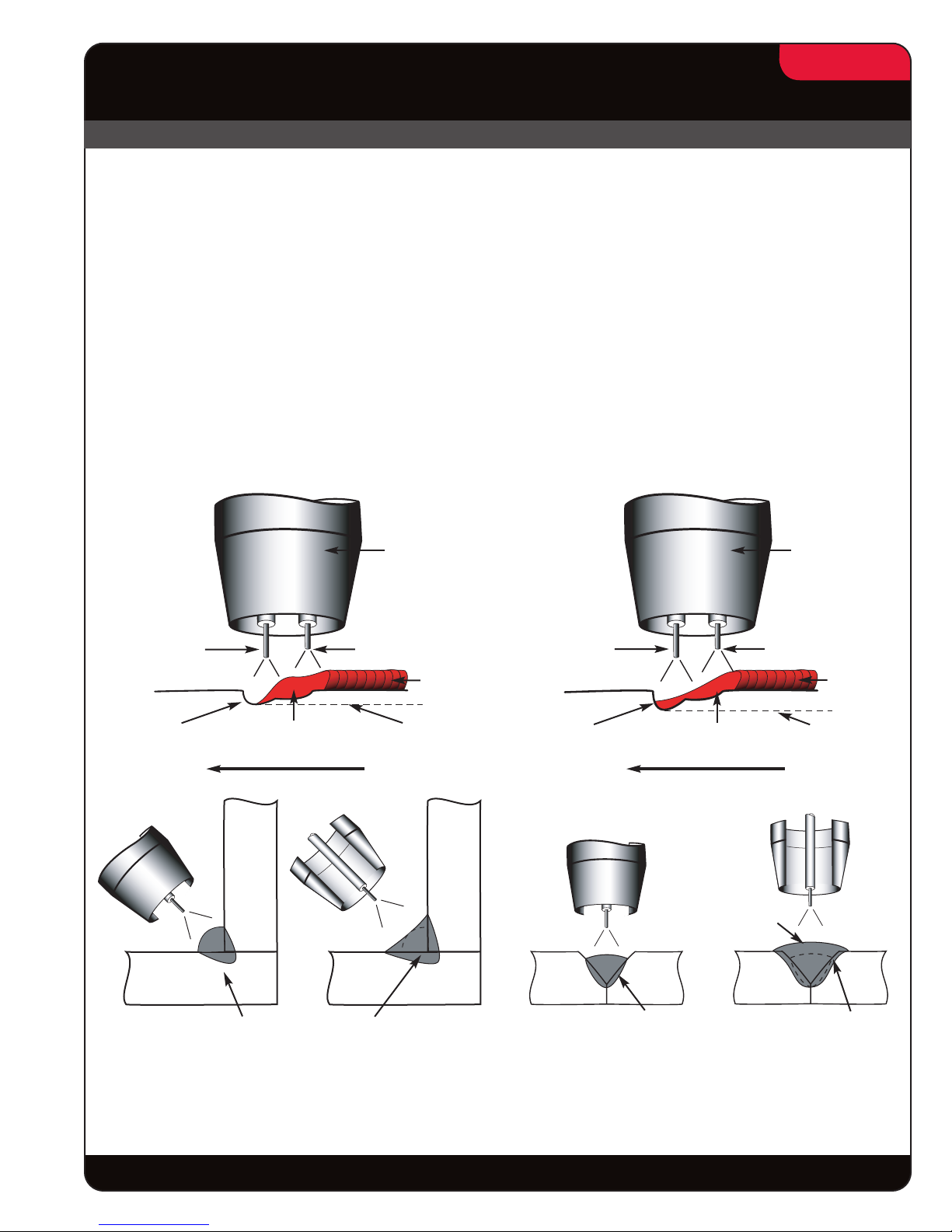
The two welding arcs common to the Tandem MIG
process have distinct functions. The lead arc (the
first arc in the direction of torch travel) is operated in
a spray transfer mode. The mode may be either a
special Tandem MIG pulse mode, an adaptive
constant voltage mode or a Tandem MIG power mode.
The lead arc’s primary function is to establish initial
root penetration and develop a molten weld pool for
the trail wire. While performing these functions the
lead wire typically accounts for 60% or more of the
total weld metal deposited. The trail arc or second arc
Lead and Trail arc functions for high speed welding
Trail arc is focused on the crest of the pool
created by the lead.
Gas Nozzle
3/16
is operated in a special Tandem MIG pulse mode.
The trail arc’s function is to add filler metal to the weld
pool and control the bead characteristics such as edge
wetting, physical contour, side-wall penetration and
weld pool follow speed. The trail arc should be kept
directly in line with the lead arc and focused on the
center of the weld pool. The trail wire melting rate
typically represents approximately 40% of the
process deposition rate. The Tandem MIG trail pulse
waveforms are designed to operate at low voltages
to limit arc interaction and minimize arc blow.
Lead and Trail arc functions for high deposition welding
The trail arc is focused on the middle of the weld pool
to create additional fill.
Gas Nozzle
Lead Arc Trail Arc
Lead Arc
Penetration
Lead
Arc
Partial
Fill
Penetration Past the Root
The Lead Arc generates the
majority of the penetration
and leaves joint requiring
additional fill.
Molten Weld
Pool
Travel Travel
Completes
Fill
downward and forward
pressure on the weld pool
for better pool follow and
Weld
Bead
Penetration
Trail
Arc
Wets Edges
The Trail Arc places a
wetting along the
bead edges.
Lead Arc Trail Arc
Lead Arc
Penetration
Penetration
The Lead Arc creates the
initial root penetration and
the majority of the joint fill.
Molten Weld
Pool
Lead
Arc
Completed
Fill
Root
The Trail Arc is focused in
the weld pool providing
additional joint side-wall
penetration and joint fill.
Weld
Bead
Penetration
Trail
Arc
Sidewall
Penetration
The future of welding is here.
®
Page 4
WAVEFORM CONTROL TECHNOLOGY
TM
APPLICATION
Tandem MIG
High-Speed and High-Deposition Welding
Using Tandem MIG
For High-Speed Applications
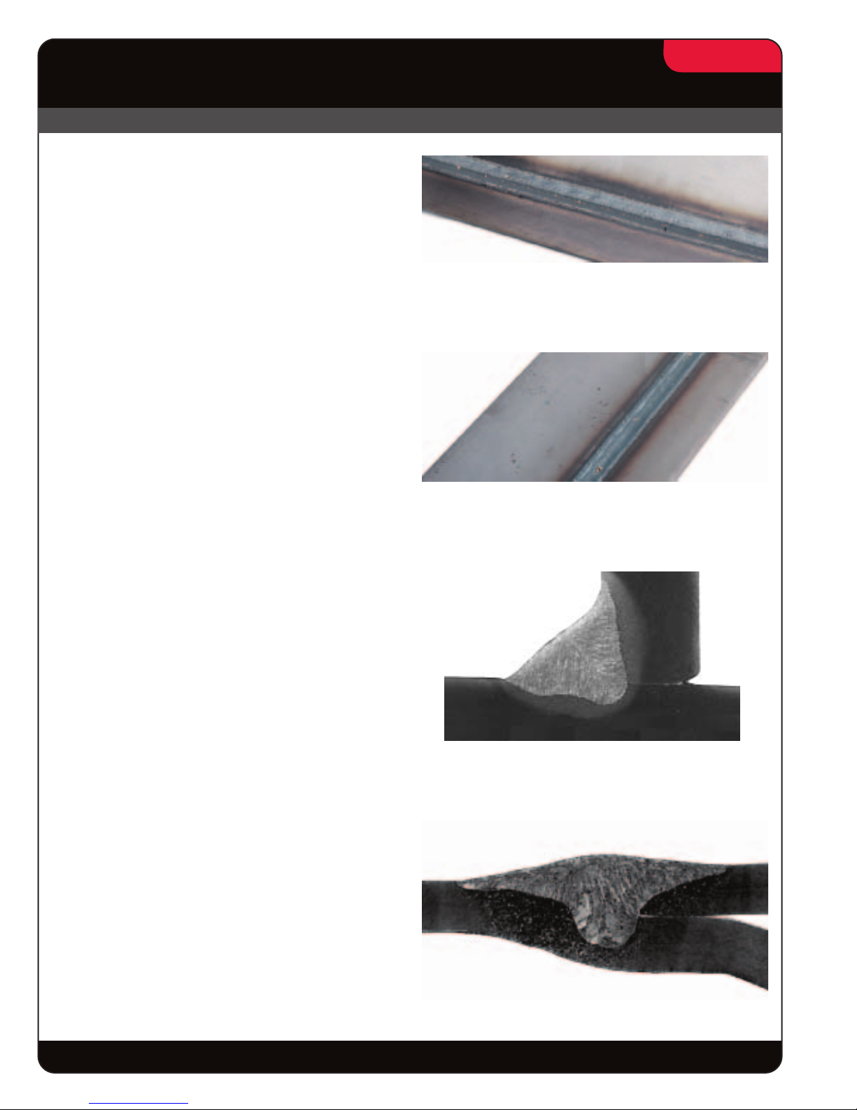
Flat and Horizontal Lap Welds
1.5 mm - 5 mm
Automotive, Tank Fabrication
Flat and horizontal lap welds common to automotive
components like control arms, stub or full chassis
frames, cross members, shock absorbers, struts,
stabilizer arms and flex axles are performed at welding
travel speeds ranging from 70 - 130 ipm. On thinner
components with metal thickness ranging from
1.5 - 3 mm, flat and horizontal lap welds are made with
(2) .035” diameter electrodes at travel speeds ranging
from 100 - 130 ipm. Thicker components with metal
thickness from 3 - 5 mm are performed with (2) .045”
diameter electrodes at travel speeds ranging from
70 - 100 ipm.
4/16
This thin gauge lap weld was made at a
travel speed of 100 ipm
Flat and Horizontal Fillet Welds
3 mm - 6 mm
General Light Gauge Steel Fabrication,
Shipbuilding, Railroad
Light gauge steel fabrication of 3 - 4 mm fillet welds
used to weld structural trusses, farm implements,
residential and commercial storage systems,
trash-hauling containers and similar components are
welded with (2) .035” diameter electrodes to produce
welds at travel speeds ranging from 80 - 100 ipm.
Larger 4 - 6 mm fillet welds common to structural
beams, light earth moving equipment, ship stiffeners,
rail cars and similar components are welded with
(2) .045” electrodes at travel speeds ranging from
50 - 80 ipm.
Joggle Joints 1.5 mm - 4 mm
Tanks and General Fabrication
Joggle joints require a careful balance of joint fill and
controlled penetration. Tandem MIG provides the
independent control of both, providing needed joint fill
without excessive penetration. Joggle welds between
1.5 and 3 mm, common to the light tank, truck bodies,
trash-hauling containers and similar components are
welded at travel speeds ranging from 80 - 120 ipm
using (2) .035” diameter electrodes. Larger 3 - 4 mm
joggle joints used in larger tanks and thicker
containers are performed at welding speeds ranging
from 40 - 80 ipm using (2) .045” diameter electrodes.
3/16” (4.8 mm) Horizontal Lap Weld
6mm Horizontal Fillet
Joggle Weld
The future of welding is here.
®
Page 5
WAVEFORM CONTROL TECHNOLOGY
TM
APPLICATION
Tandem MIG
High-Speed and High-Deposition Welding
Using Tandem MIG
For High-Deposition Applications
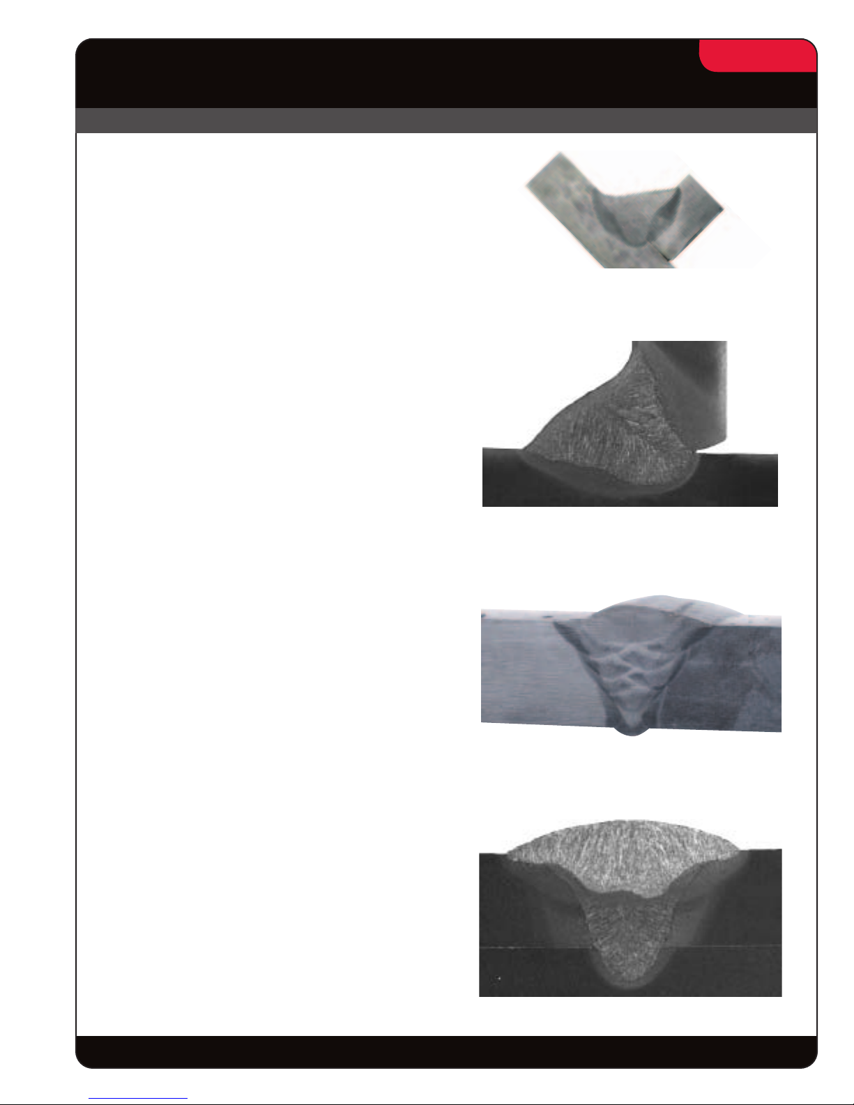
Flat and Horizontal Fillet Welds
6 mm and Larger
Railroad, Structural, Industrial
Equipment, Ship Building, Off Road
Wheel Manufacturing
Flat and horizontal fillets common to structural
building components, offshore platforms, railcar
haulers, machine bases, large vehicle wheels,
undercarriages/truck suspensions and other fabricated
components of metal thickness of 6 mm and greater
are performed at deposition rates ranging from
21 - 35 lbs./hr.
Single pass 5/16” flat fillets are commonly welded
at 24 - 30 ipm with (2) .045” diameter electrodes.
5/16
1/2” Flat Fillet at 20 ipm
Single pass 5/16” flat fillets are commonly welded
at 27 - 40 ipm with (2) .052” diameter electrodes.
Bevel and “V” Groove Joints
Heavy Plate Fabrication, Structural
Members and Industrial Equipment
Single and multi-pass beveled butt welds used
in industries fabricating ship hulls, earth moving
equipment, structural platforms, pressure vessels,
beams and similar heavy plate weldments are
performed at deposition rates ranging from
22 - 35 lbs./hr. Welds are commonly performed using
like electrode diameters, either .045 or .052 inch
diameter. The lead electrode provides root penetration,
the trail electrode adds to sidewall penetration.
“J” and “U” Groove Butt Welds
Earth Moving Equipment and
Heavy Plate Fabrication
Single and multi pass “J” and “U” groove joints
common to undercarriages, rollover protection
equipment, sticks, booms, fifth wheels, frames,
hydraulic cylinders, pant legs and similar earth
moving equipment components are welded at
deposition rates ranging from 22 - 35 lbs./hr. Welds
are performed at a 30 - 50% reduction in heat input
when compared to larger diameter single electrode
processes. Lower heat input can substantially reduce
post weld straightening activity caused by distortion.
8 mm Horizontal Fillet
Multi-pass Butt Weld
2 Pass “J” Groove
The future of welding is here.
®
Page 6

WAVEFORM CONTROL TECHNOLOGY
TM
APPLICATION
Tandem MIG
High-Speed and High-Deposition Welding
Comparing High-Speed Tandem MIG
To Single Wire GMAW Processes
Better Weld Metal Follow Characteristics:
Problem - Single Wire GMAW
As higher travel speeds are explored with conventional
single solid and metal cored wire GMAW processes
one of the factors that limits obtainable travel speeds
is a phenomenon referred to as “bead humping” or
lack of follow. The lack of follow occurs as a number
of physical metal flow requirements break down. The
coalescent properties of the weld pool are not strong
enough to pull the puddle along while, at the same
time, the higher travel speeds limit the heating of the
plate that would normally allow the weld pool to wet
or flow along the weld bead edges.
Solution - Tandem MIG
The spacing of the two arcs of the Tandem MIG
process is designed to overcome the lack of follow
associated with single wire GMAW processes. The
lead arc provides initial penetration into the base plate
and a preheating of the plate for the trail arc. The trail
arc rides the pool created by the lead electrode, the
pressure from the trail arc flattens the created weld
pool to eliminate the tendency for the pool to rise and
hump. The applied weld pool pressure from the trail
arc is used to not only limit the tendency of the lead
weld pool to hump and lose follow capability, but the
pressure is adjustable, allowing the bead contour to be
modified to meet application requirements.
6/16
12 Gauge Lap Weld
at 120 ipm travel
Reduced Tendency Towards Burn-through and Undercut
Problem - Single Wire GMAW
Increased travel speeds require the use of larger wire
diameters or higher wire feed speeds. Both choices
will cause an increase in current draw. The added
current draw creates added penetration that must
be managed. With a single wire GMAW process the
penetration is most intense at the point where the
axial flow of material from the welding wire is directed
on to the plate. This area is focused to a small area
that is generally the cross-sectional area of the
welding wire diameter. In order to manage the
additional finely focused penetration wire placement
becomes more demanding, joint fit-up becomes
more critical. If joint alignment is not maintained and
the welding arc wanders off the seam, concentrating
the arc on a single metal thickness, burn-through is a
common result. If joint fit-up is not maintained welds
often penetrate well into the open joint creating an
unacceptable undercut. If the penetration is not
successfully managed the common result is costly
increased rework or scrap.
Solution - Tandem MIG
The Tandem MIG process is able to achieve the
high wire feed requirements of high speed welding
without creating excessive penetration. The required
wire feed total for high speed welding is shared by
the two electrodes forming the Tandem MIG process.
The shared wired feed speed not only reduces the
current draw on each individual arc but disperses
the total welding energy over two separate focal
points. The separation of the two focal penetration
points allows more metal to be deposited without
excessive penetration. The lead arc is focused on
the plate while the trail arc is focused on the molten
pool created by the lead arc. The trail wire energy is
applied to the pool and not directly onto the plate. This
limits the overall penetration and allows the process
to be tolerant of joint misalignment and joint gaps.
The future of welding is here.
®
Page 7

WAVEFORM CONTROL TECHNOLOGY
TM
APPLICATION
Tandem MIG
High-Speed and High-Deposition Welding
Comparing High-Speed Tandem MIG
To Single Wire GMAW Processes
Travel Speed Comparison
Typical Travel Speeds
Travel
Speed
(ipm)
140
120
100
80
60
40
Single Wire GMAW vs Tandem MIG
7/16
Single Wire GMAW
Tandem MIG
2mm 2.5mm 3mm 4mm 5mm
Lap Weld Size
Comparing High-Deposition Tandem MIG
To Single Wire GMAW Process
Higher Deposition rates
Problem - Single Wire GMAW
A conventional single wire GMAW process has an
optimum operating range based primarily on wire
diameter, shielding gas and wire feed speed.
Attempting to maximize deposition rates for a given
wire diameter requires increasing the wire feed rate
to the top or beyond its defined operating range. As
the process is pushed to its limit, arc instability is often
a result. Arc instability creates increased spatter levels
and weld porosity. The elevated welding currents
create weld pool turbulence that can cause root
porosity, or porosity just below the surface of the
weld bead.
Solution - Tandem MIG
The two-wire electrode configuration of the Tandem
MIG process allows a higher total wire feed rate,
creating a higher deposition rate. Each electrode in
the Tandem configuration can be operated within an
optimum operating range as defined by a single wire
process. Both the lead and the trail electrode may be
operated in a stable operating range, while the
combined wire feed speed of the two electrodes often
exceed a useable single wire process by 35-80%.
The future of welding is here.
®
Page 8

WAVEFORM CONTROL TECHNOLOGY
TM
APPLICATION
Tandem MIG
High-Speed and High-Deposition Welding
Comparing High-Deposition Tandem MIG
To Single Wire GMAW Process
Reduced Heat Input and Improved Bead Profiles
Problem - Single Wire GMAW
A single wire GMAW process has a useable weld
metal deposition rate based on wire feed speed and
wire diameter. In an attempt to increase weld metal
deposit rates, rather than push a given wire diameter
to unstable wire feed speeds, it is often common
practice to increase the wire diameter and operate
within stable wire feed ranges. The increase in wire
diameter increases the required current draw
associated with a given weld metal deposit rate.
Increased current draw produces higher heat inputs
leading to part distortion and a large fluid weld pool
that is difficult to control.
Solution - Tandem MIG
With the Tandem MIG process the two smaller
diameter electrodes produce a lower heat input and
improved weld pool control when compared to a larger
single electrode process attempting to perform similar
welds. When compared to larger diameter electrode
processes,Tandem MIG typically reduces heat input
by as much as 30-50%. The trail electrode in the
Tandem MIG process is operated in a special Tandem
MIG pulse mode designed to cool the weld pool
created by the lead electrode. The combination of
lower total heat input and the cooling affect of the trail
electrode, allows the trail electrode to be used to help
control weld bead contour. This provides the ability
to better stack horizontal weld beads and produce
flatter horizontal fillets while working at higher
deposition rates.
8/16
REDUCED HEAT INPUT EXAMPLE
5/16” Horizontal Fillet Weld
PROCESS
GMAW - 1/16” dia. - ER70S - 6 470 31 17.8 17.7 49.4
FCAW - 3/32” dia. - ER70T - 1 435 29.5 15.8 15.7 49.0
GMAW - 3/32” dia. - ER70C - 6M 500 34 16.2 16.1 63.3
Lead .045” dia. ER70S - 6 300 23
Trail .045” dia. ER70S - 6 250 24
CURRENT
DRAW
(amps)
ARC
VOLTAGE
(DC+)
Tandem MIG
DEPOSIT
RATE
(lbs./hr)
23.3 23.1 33.5
TRAVEL SPEED
(ipm)
HEAT INPUT
Kj/in
The future of welding is here.
®
Page 9

WAVEFORM CONTROL TECHNOLOGY
TM
APPLICATION
Tandem MIG
High-Speed and High-Deposition Welding
Comparing High-Deposition Tandem MIG
To Single Wire GMAW Process
Deposition Rate Comparison
Weld Metal Deposition Rate Single Wire GMAW vs Tandem MIG
Lbs./Hr.
Single Wire GMAW
40
30
9/16
Tandem MIG
20
10
1/4”
Horizontal
Fillet
5/16”
Horizontal
Fillet
3/8”
Flat
Fillet
Joint Type
5/8”
J Groove
Multi-Pass
Beveled Butt
The future of welding is here.
®
Page 10

WAVEFORM CONTROL TECHNOLOGY
TM
APPLICATION
Tandem MIG
10/16
High-Speed and High-Deposition Welding
Using Tandem MIG
Understanding Operating Variables
The general rules governing operating variables for single wire GMAW arc welding also apply to Tandem MIG
welding. However there are additional considerations that must be kept in mind when welding with multiple arcs.
Since the two arcs will interact, the type of power fed to each arc, the wire feed speed ratio between lead and trail,
the arc lengths, the wire positioning, and torch angles must be set correctly. The enclosed procedures are starting
points and may need to be altered based on specific application conditions. Adherence to the following guidelines
will assist in achieving the maximum potential of the process.
Lead Arc
The lead arc creates the majority of the penetration and should represent the majority of the total deposition
rate of the process. When using like diameter electrodes for the lead and the trail, the lead should represent
approximately 60% of the total wire feed. In the case where a larger wire diameter is used as a lead (for added
penetration) the lead should represent approximately 60% or more of the total deposition. The lead arc can be
operated in a Tandem pulse, CV or Power mode. Pulse is recommended for the high deposition procedures.
Power mode or CV may be used for greater lead arc stability in high travel speed applications.
Trail Arc
The trail arc is used to cool the weld pool and control the bead contour and is always operated in the Tandem
pulse mode. The trail should be kept directly in line with the lead arc and focused on the center of the weld pool.
The trail wire should represent approximately 40 % of the process deposition rate. The Tandem MIG trail pulse
waveforms are designed to operate at low voltages to limit arc interaction and minimize arc blow.
Torch Positioning
Torch positioning may be altered for specific applications. A 5-degree push angle is recommended for high
deposition welding. A (0-5)-degree angle is recommended for high speed welding.
Travel Angle
Push Angle
Push Angle
Travel
Travel
Directionl
Direction
(Beveled Butt, Fillets, Laps
Flat Welds
45°
Joint Angle
90°
65°
Horizontal Welds
Lap
1/2” Wire Dia.
40°
A 5-degree push angle
is recommended
The future of welding is here.
Horizontal Welds
Small Fillet
Horizontal Welds
Large Fillet
®
Page 11

WAVEFORM CONTROL TECHNOLOGY
TM
APPLICATION
Tandem MIG
11/16
High-Speed and High-Deposition Welding
Using Tandem MIG
Understanding Operating Variables
Shielding Gas
The lead and trail shielding gas should be of the same mixture and supplied through separate flow regulators. Gas
flow per electrode should be a minimum of 40-cfh each. High deposition procedures may require flow rates as
high as 70 cfh per electrode. High deposition multi-pass applications may require that a trailing gas is applied to
eliminate nitrogen pick-up. The Tandem MIG process requires a binary gas mixture capable of supporting a spray
transfer. Argon/Carbon dioxide or Argon/ Oxygen are the preferred mixtures.
1. 90/10%, Ar/CO
2. 82-95% argon with a Ar/C02 binary mixture is a useable range, The higher CO2% will promote added
penetration but may produce added spatter. The lower CO
3. 95/5%, Ar/O2is recommended for high speed welding of thin gage material under 3mm. The
mixture will provide improved wetting at bead edges and reduced tendency to erode away
edges of lap welds.
Work Lead Connection
Tandem MIG welding should be performed welding in the direction from the work lead connection. Welding
towards the work lead connection may cause a convex weld bead and undercut.
is preferred for most welding applications.
2
% will produce less spatter.
2
Joint Selection
The Tandem MIG process is ideal for many joint configurations. A joint application rating is as follows:
Excellent
1. Lap welds in the flat, horizontal, 3 o'clock position.
2. Fillet welds in the flat and horizontal positions.
3. Joggle welds in the flat position.
4. Beveled butt welds in flat position.
5. "J" Groove welds.
6. Rotated roundabouts, lap and joggle welds.
Good
1. Beveled butt welds in horizontal position.
2. Horizontal flare joint.
Poor
1. Seamer applications.
2. Joints known to be subject to arc blow.
3. Weld joints that have multiple or severe turns in direction or contour.
4. Thin gage square edge butt welds.
The future of welding is here.
®
Page 12

WAVEFORM CONTROL TECHNOLOGY
TM
APPLICATION
Tandem MIG
High-Speed and High-Deposition Welding
Configuring Tandem MIG
Hard Automation Systems
Models: AD1202 - 1 and AD1202 - 2
H
C
12/16
B
G
A
F
I
Item Component AD1202-1 AD1202-2 Qty
A Power Source Tandem MIG Power Wave 455M Robotic or K2262-1-TM 2
Tandem MIG Power Wave 655 Robotic K1519-1-TM 2
B Wire Feeder Power Feed 10R Wire Feeder K1780-2 K1780-2 2
C Interface Controller G3207-185 G3207-185 1
D DeviceNet Tee S23383-3 S23383-3 2
Terminating Resistor S23383-5 S23383-5 1
E DeviceNet Communication Cables (drops) (20 in.) S23383-4 S23383-4 2
F DeviceNet Communication Cables (trunk line) (19.5 ft.) S23383-2 S23383-2 1
G Communication cables. Power source to wire feeders (25 ft.) K1785-25 K1795-25 2
Cable jumper, 22 pin to 14 pin (18 inch) K1804-2 2
800 amp Tandem MIG torch
H
900 amp Tandem MIG torch
I 4/0 Work (ground) cable (25 ft.) L-4/0-25-14-14 L-4/0-25-14-14 2
Not Shown Drive Roll Kit KP1505-XX KP1505-XX 2
or
D
S22693-XXX
E
or
G3494-XA
A
S22693-XXX
or
G3494-XA
1
Not Shown Wire Straightener K1733-1 K1733-1 2
Not Shown Process Sense Leads K940-25 K940-25 2
Not Shown 4/0 Electrode Cable (25 ft.) L-4/0-25-14-14 L-4/0-25-14-14 2
Not Shown Torch water cooling package AD1013-3 AD1013-3 1 or 3*
* S22693-XXX series torches require (1) water cooling package per torch, G3494-XA series torches require (3)
The future of welding is here.
®
Page 13

WAVEFORM CONTROL TECHNOLOGY
TM
APPLICATION
Tandem MIG
High-Speed and High-Deposition Welding
Configuring Tandem MIG
Robotic Systems
Models: AD1201 - 1 and AD1201 - 2
G
E
13/16
H
B
D
A
F
C
A
Item Component AD1201-1 AD1201-2 Qty
A Power Source Tandem MIG Power Wave 455M Robotic or K2262-1-TM 2
A Tandem MIG Power Wave 655 Robotic K1519-1-TM 2
B Wire feeder Power Feed 10R wire feeder K1780-2 K1780-2 2
C ArcLink cables, Power source to robot controller (25 ft.) S23394-18 S23394-18 2
D Communication cables, Power source to wire feeders (25 ft.) K1785-25 K1795-25 2
Cable jumper, 22-pin to 14-pin (18 in.) K1804-2 2
E 4/0 Work (ground) cable (25 ft.) L-4/0-25-14-14 L-4/0-25-14-14 2
Fanuc RJ3iB robot and controller
F
Arc tool software 6.4 or above
Dual channel DeviceNet board S23319-62 S23319-62 1
24 Volt Power cable S23394-9 S233394-9 1
800 amp Tandem MIG torch
G
900 amp Tandem MIG torch
H 9 ft. Boom for wire feeder mounting AD1038-3 AD1038-3 1
Not Shown Reaming Station M18426-1 M18426-1 1
Not Shown Drive Roll Kit KP1505-XX KP1505-XX 2
Not Shown Wire Straightener K1733-1 K1733-1 2
Not Shown Process Sense Leads K940-25 K940-25 2
Not Shown 4/0 Electrode Cable (25 ft.) L-4/0-25-14-14 L-4/0-25-14-14 2
Not Shown Torch water cooling package AD1013-3 AD1013-3 1 or 3*
or
100 or 120 Series
RJ3iB Controller
S22693-XXX
or
G3494-XA
100 or 120 Series
RJ3iB Controller
S22693-XXX
or
G3494-XA
1
1
* S22693-XXX series torches require (1) water cooling package per torch, G3494-XA series torches require (3)
The future of welding is here.
®
Page 14

WAVEFORM CONTROL TECHNOLOGY
TM
APPLICATION
Tandem MIG
High-Speed and High-Deposition Welding
Lincoln Welding Systems Featuring Tandem MIG
14/16
Power Feed 10R Wire Feeder
Compact Wire Drive System for Automation
The Power Feed 10R is a high performance,
digitally controlled wire feeder designed to be a part
of a modular, multi-process welding system. It is
specifically designed to mount to a robot arm or to
use in hard automation applications. Modular systems
can be arranged in a variety of ways for optimum,
customized performance and easy maintenance. This
four drive roll feeder operates on 40VDC input power
and is designed to be used with ArcLink™ Robotic
Power Wave
the feeder, power source and existing equipment
creates the foundation for a system with superior
welding performance and reliability.
Patented Drive Roll System
The Power Feed 10R is a basic wire feeder with an
optimized design, which consists of an industrial motor
driving the feeder mechanism in a sheet metal frame.
The logic for controlling the wire feeder resides in a
PC board inside the robotic power source.
®
power sources. Close integration of
Advantage Lincoln
• Digitally controlled by the Power Wave power source,
yielding the best performance in the industry.
• Use with Lincoln power sources featuring ArcLink, the
leading digital communications protocol for welding,
making it the best choice for seamless integration with
the power source and networked equipment.
• Tachometer feedback provides calibrated and precise
control of wire feed speed.
• Feeder brakes from maximum speed to zero in
milliseconds, minimizing the chance of wire sticking
in the puddle.
• Select standard or high speed gears for wide wire
feed speed range.
• Split wire guides provide trouble-free feeding and
offer fast, tool-less wire installation, changeover
and maintenance.
• Easy-to-read gauge for accurate drive roll tension.
• Brass-to-brass connections for good connectivity
between feeder and gun.
• Modular construction for easy servicing.
• Self loading wire feature for easy set-up.
The future of welding is here.
®
Page 15

WAVEFORM CONTROL TECHNOLOGY
TM
APPLICATION
Tandem MIG
High-Speed and High-Deposition Welding
Lincoln Welding Systems Featuring Tandem MIG
15/16
Power Wave 455M
For welding thicker materials in robotics, hard
automation, PLC and semiautomatic applications,
choose the Power Wave 455M. The power source
features Waveform Control Technology for superior arc
performance on a variety of materials, including steel,
stainless steel, aluminum and nickel alloys. Custom
control of the arc for each wire type and size provide
consistent welds time after time. These Power Waves
are designed to be part of a modular, multi-process
welding system.
The future of welding is here.
Power Wave 655R
The Power Wave 655R was designed for Robotic and
Hard Automation applications that require extra power
(650 Amps at 100% Duty Cycle).
• Digital Communications enable the Power Wave to
connect seamlessly to robot controllers and hard
automation PLCs.
• The Ethernet/DeviceNet Gateway provides networking
capabilities and allows process and production monitoring.
• Software-based controls can be upgraded as new
features become available.
• The Power Wave 655R has an output range of
20-880 Amps.
®
Page 16

WAVEFORM CONTROL TECHNOLOGY
TM
APPLICATION
Tandem MIG
High-Speed and High-Deposition Welding
Lincoln Consumables used with Tandem MIG
SuperArc®/SuperGlide
Lincoln’s SuperArc, our premium copper-coated MIG wire, and
SuperGlide, our premium bare wire, are the choice of welders
and welding decision-makers everywhere because of their
exceptional consistency, feedability, and arc action.
A better arc means less spatter, less clean-up, and improved
productivity – and premium SuperArc and SuperGlide deliver
the best arc in MIG welding.
Our MicroGuard™ Ultra surface treatment,
with proprietary arc enhancement agents,
facilitates excellent weld puddle control, very
good wetting action, straight bead edges, and
a wider operating range.
The exceptional feeding characteristics of
SuperGlide, made possible by MicroGuard Ultra
surface treatment, translate to reduced
down-time and high operator appeal.
Accu-Pak
100% Recyclable Patented Package — when the
wire is consumed, just remove the components,
collapse the box and throw into the recycle bin.
Lifting Strap for ease of movement from one location
to the next. Patented Ring Design.
Accu-Trak
This Accu-Trak Drum Payoff Kit is made of a
durable plastic for superior strength and integrity.
It also features two viewing windows 180° apart
from one another for easy viewing of the wire as
it is paying off.
A Payoff Kit must be used with Accu-Trak Drums
to ensure precise feeding. The fitting on top of the
Payoff Kit has a 1/2-14 NPT internal pipe thread
to facilitate the connection of the conduit to 500 lb.
Accu-Trak drums.
Customer Assistance Policy
The business of The Lincoln Electric Company is manufacturing and selling high quality welding equipment,
consumables, and cutting equipment. Our challenge is to meet the needs of our customer and to exceed
their expectations. On occasion, purchasers may ask Lincoln Electric for advice or information about their
use of our products. We respond to our customers based on the best information in our possession at that
time. Lincoln Electric is not in a position to warrant or guarantee such advice, and assumes no liability, with
respect to such information or advice. We expressly disclaim any warranty of any kind, including any
warranty of fitness for any customer’s particular purpose, with respect to such information or advice. As a
matter of practical consideration, we also cannot assume any responsibility for updating or correcting any
such information or advice once it has been given, nor does the provision of information or advice create,
expand or alter any warranty with respect to the sale of our products.
Lincoln Electric is a responsive manufacturer, but the selection and use of specific products sold by
Lincoln Electric is solely within the control of, and remains the sole responsibility of the customer. Many
variables beyond the control of Lincoln Electric affect the results obtained in applying these types of
fabrication methods and service requirement.
Subject to change - This information is accurate to the best of our knowledge at the time of printing.
Please refer to www.lincolnelectric.com for any updated information.
®
®
®
16/16
WHAT IS NEXTWELD?
The challenges facing industrial
fabricators today are increasingly
difficult. Rising labor, material, and
energy costs, intense domestic and
global competition,
a dwindling pool of
skilled workers,
more stringent and
specific quality
demands.
Through our
commitment to
extensive research
and investments in
product
development,
Lincoln Electric has
established an industry benchmark for
applying technology to improve the
quality, lower the cost and enhance the
performance of arc welding processes.
Advancements in power electronics,
digital communications and Waveform
Control Technology™ are the foundation
for many of the improvements.
NEXTWELD brings you a series of
Process, Technology, Application and
Success Story documents like this one.
NEXTWELD explains how technologies,
products, processes and applications are
linked together to answer the important
questions that all businesses face:
• How can we work faster, smarter,
more efficiently?
• How can we get equipment and
people to perform in ways they’ve
never had to before?
• How do we stay competitive?
NEXTWELD is the future of welding but
its benefits are available to you today.
Ask your Lincoln Electric representative
how to improve the flexibility, efficiency
and quality of your welding operations to
reduce your cost of fabrication.
THE LINCOLN ELECTRIC COMPANY
www.lincolnelectric.com
1.216.481.8100
The future of welding is here.
®
 Loading...