

Page 1

Safety Depends on You
RETURN TO MAIN MENU
Lincoln equipment is designed
and built with safety in mind.
However, your overall safety can
be increased by proper installation ... and thoughtful operation
on your part. DO NOT INSTALL,
OPERATE OR REPAIR THIS
EQUIPMENT WITHOUT READING THIS MANUAL AND THE
SAFETY PRECAUTIONS CONTAINED THROUGHOUT. And,
most importantly, think before you
act and be careful.
SVM200-A
April, 2010
VRTEX™360
For use with machine code number: AD1332-1
AD1332-2
NOTICE
The VRTEX
al reality arc welding
training machine only
and NOT a real arc
welder. When welding
with arc welding equipment, be aware of all
standard safety practices
associated with arc welding. Some standard warnings are included in this
manual.
TM
360 is a virtu-
SERVICE MANUAL
View Safety Info View Safety Info View Safety Info View Safety Info
Return to Master TOC Return to Master TOC Return to Master TOC Return to Master TOC
Cleveland, Ohio 44117-1199 U.S.A. TEL: 888.935.3878 FAX: 216.383.8823 WEB SITE: www.VRTEX360.com
Copyright © Lincoln Global Inc.
• World's Leader in Welding and Cutting Products •
• Sales and Service through Subsidiaries and Distributors Worldwide •
Page 2

Page 3

i i
SAFETY
WARNING
CALIFORNIA PROPOSITION 65 WARNINGS
Diesel engine exhaust and some of its constituents
are known to the State of California to cause cancer, birth defects, and other reproductive harm.
The Above For Diesel Engines
ARC WELDING CAN BE HAZARDOUS. PROTECT YOURSELF AND OTHERS FROM POSSIBLE SERIOUS INJURY OR DEATH.
KEEP CHILDREN AWAY. PACEMAKER WEARERS SHOULD CONSULT WITH THEIR DOCTOR BEFORE OPERATING.
Read and understand the following safety highlights. For additional safety information, it is strongly recommended that you purchase a copy of “Safety in Welding & Cutting - ANSI Standard Z49.1” from the American Welding Society, P.O. Box 351040,
Miami, Florida 33135 or CSA Standard W117.2-1974. A Free copy of “Arc Welding Safety” booklet E205 is available from the
Lincoln Electric Company, 22801 St. Clair Avenue, Cleveland, Ohio 44117-1199.
BE SURETHATALL INSTALLATION, OPERATION, MAINTENANCEAND REPAIR PROCEDURES ARE PERFORMED ONLY BY QUALIFIED INDIVIDUALS.
The engine exhaust from this product contains
chemicals known to the State of California to cause
cancer, birth defects, or other reproductive harm.
The Above For Gasoline Engines
FOR ENGINE
powered equipment.
1.a. Turn the engine off before troubleshooting and maintenance
work unless the maintenance work requires it to be running.
____________________________________________________
1.b. Operate engines in open, well-ventilated
areas or vent the engine exhaust fumes
outdoors.
____________________________________________________
1.c. Do not add the fuel near an open flame welding arc or when the engine is running. Stop
the engine and allow it to cool before refueling
to prevent spilled fuel from vaporizing on contact with hot engine parts and igniting. Do not
spill fuel when filling tank. If fuel is spilled,
wipe it up and do not start engine until fumes
have been eliminated.
____________________________________________________
1.d. Keep all equipment safety guards, covers and devices in position and in good repair.Keep hands, hair, clothing and tools
away from V-belts, gears, fans and all other moving parts when
starting, operating or repairing equipment.
____________________________________________________
1.e. In some cases it may be necessary to remove safety
guards to perfor m required maintenance. Remove
guards only when necessary and replace them when the
maintenance requiring their removal is complete.
Always use the greatest care when working near moving
parts.
___________________________________________________
1.f. Do not put your hands near the engine fan.Do
not attempt to override the governor or idler by
pushing on the throttle control rods while the
engine is running.
1.h. To avoid scalding, do not remove the
radiator pressure cap when the engine is
hot.
ELECTRIC AND
MAGNETIC FIELDS
may be dangerous
2.a. Electric current flowing through any conductor causes
localized Electric and Magnetic Fields (EMF). Welding
current creates EMF fields around welding cables and
welding machines
2.b. EMF fields may interfere with some pacemakers, and
welders having a pacemaker should consult their physician
before welding.
2.c. Exposure to EMF fields in welding may have other health
effects which are now not known.
2.d. All welders should use the following procedures in order to
minimize exposure to EMF fields from the welding circuit:
2.d.1.
Route the electrode and work cables together - Secure
them with tape when possible.
2.d.2. Never coil the electrode lead around your body.
2.d.3. Do not place your body between the electrode and
work cables. If the electrode cable is on your right
side, the work cable should also be on your right side.
___________________________________________________
1.g. To prevent accidentally starting gasoline engines while
turning the engine or welding generator during maintenance
work, disconnect the spark plug wires, distributor cap or
magneto wire as appropriate.
Return to Master TOC Return to Master TOC Return to Master TOC Return to Master TOC
2.d.4. Connect the work cable to the workpiece as close as
possible to the area being welded.
2.d.5. Do not work next to welding power source.
VRTEXTM360
Page 4

ii ii
SAFETY
ELECTRIC SHOCK can kill.
3.a. The electrode and work (or ground) circuits
are electrically “hot” when the welder is on.
Do not touch these “hot” parts with your bare
skin or wet clothing. Wear dry, hole-free
gloves to insulate hands.
3.b. Insulate yourself from work and ground using dry insulation.
Make certain the insulation is large enough to cover your full
area of physical contact with work and ground.
In addition to the normal safety precautions, if welding
must be performed under electrically hazardous
conditions (in damp locations or while wearing wet
clothing; on metal structures such as floors, gratings or
scaffolds; when in cramped positions such as sitting,
kneeling or lying, if there is a high risk of unavoidable or
accidental contact with the workpiece or ground) use
the following equipment:
• Semiautomatic DC Constant Voltage (Wire) Welder.
• DC Manual (Stick) Welder.
• AC Welder with Reduced Voltage Control.
3.c. In semiautomatic or automatic wire welding, the electrode,
electrode reel, welding head, nozzle or semiautomatic
welding gun are also electrically “hot”.
3.d. Always be sure the work cable makes a good electrical
connection with the metal being welded. The connection
should be as close as possible to the area being welded.
3.e. Ground the work or metal to be welded to a good electrical
(earth) ground.
3.f.
Maintain the electrode holder, work clamp, welding cable and
welding machine in good, safe operating condition. Replace
damaged insulation.
3.g. Never dip the electrode in water for cooling.
3.h. Never simultaneously touch electrically “hot” par ts of
electrode holders connected to two welders because voltage
between the two can be the total of the open circuit voltage
of both welders.
3.i. When working above floor level, use a safety belt to protect
yourself from a fall should you get a shock.
3.j. Also see Items 6.c. and 8.
ARC RAYS can burn.
4.a. Use a shield with the proper filter and cover
plates to protect your eyes from sparks and
the rays of the arc when welding or observing
open arc welding. Headshield and filter lens
should conform to ANSI Z87. I standards.
4.b. Use suitable clothing made from durable flame-resistant
material to protect your skin and that of your helpers from
the arc rays.
4.c. Protect other nearby personnel with suitable, non-flammable
screening and/or warn them not to watch the arc nor expose
themselves to the arc rays or to hot spatter or metal.
FUMES AND GASES
can be dangerous.
5.a. Welding may produce fumes and gases
hazardous to health. Avoid breathing these
fumes and gases. When welding, keep
your head out of the fume. Use enough
ventilation and/or exhaust at the arc to keep
fumes and gases away from the breathing zone. When
welding with electrodes which require special
ventilation such as stainless or hard facing (see
instructions on container or MSDS) or on lead or
cadmium plated steel and other metals or coatings
which produce highly toxic fumes, keep exposure as
low as possible and within applicable OSHA PEL and
ACGIH TLV limits using local exhaust or mechanical ventilation. In confined spaces or in some circumstances,
outdoors, a respirator may be required. Additional precautions are also required when welding on galvanized
steel.
5. b. The operation of welding fume control equipment is affected
by various factors including proper use and positioning of the
equipment, maintenance of the equipment and the specific
welding procedure and application involved. Worker exposure level should be checked upon installation and periodically thereafter to be certain it is within applicable OSHA PEL
and ACGIH TLV limits.
5.c.
Do not weld in locations near chlorinated hydrocarbon
coming from degreasing, cleaning or spraying operations.
The heat and rays of the arc can react with solvent vapors
form phosgene, a highly toxic gas, and other irritating products.
vapors
to
Return to Master TOC Return to Master TOC Return to Master TOC Return to Master TOC
5.d. Shielding gases used for arc welding can displace air and
cause injur y or death. Always use enough ventilation,
especially in confined areas, to insure breathing air is safe.
5.e. Read and understand the manufacturer’s instructions for this
equipment and the consumables to be used, including the
material safety data sheet (MSDS) and follow your
employer’s safety practices. MSDS forms are available from
your welding distributor or from the manufacturer.
5.f. Also see item 1.b.
VRTEXTM360
Page 5
iii iii
SAFETY
WELDING and CUTTING
SPARKS can
cause fire or explosion.
6.a.
Remove fire hazards from the welding area.
If this is not possible, cover them to prevent
Remember that welding sparks and hot
materials from welding can easily go through small cracks
and openings to adjacent areas. Avoid welding near
hydraulic lines. Have a fire extinguisher readily available.
6.b. Where compressed gases are to be used at the job site,
special precautions should be used to prevent hazardous
situations. Refer to “Safety in Welding and Cutting” (ANSI
Standard Z49.1) and the operating information for the
equipment being used.
6.c. When not welding, make certain no part of the electrode
circuit is touching the work or ground. Accidental contact can
cause overheating and create a fire hazard.
6.d. Do not heat, cut or weld tanks, drums or containers until the
proper steps have been taken to insure that such procedures
will not cause flammable or toxic vapors from substances
inside. They can cause an explosion even
been “cleaned”. For information, purchase “Recommended
Safe Practices for the
Containers and Piping That Have Held Hazardous
Substances”, AWS F4.1 from the American Welding Society
(see address above).
6.e. Vent hollow castings or containers before heating, cutting or
welding. They may explode.
Sparks and spatter are thrown from the welding arc. Wear oil
6.f.
free protective garments such as leather gloves, heavy shirt,
cuffless trousers, high shoes and a cap over your hair. Wear
ear plugs when welding out of position or in confined places.
Always wear safety glasses with side shields when in a
welding area.
6.g. Connect the work cable to the work as close to the welding
area as practical. Work cables connected to the building
framework or other locations away from the welding area
increase the possibility of the welding current passing
through lifting chains, crane cables or other alternate circuits.
This can create fire hazards or overheat lifting chains or
cables until they fail.
6.h. Also see item 1.c.
the welding sparks from starting a fire.
though
they have
Preparation
for Welding and Cutting of
CYLINDER may explode
if damaged.
7.a. Use only compressed gas cylinders
containing the correct shielding gas for the
process used and properly operating
regulators designed for the gas and
pressure used. All hoses, fittings, etc. should be suitable for
the application and maintained in good condition.
7.b. Always keep cylinders in an upright position securely
chained to an undercarriage or fixed support.
7.c. Cylinders should be located:
• Away from areas where they may be struck or subjected to
physical damage.
• A safe distance from arc welding or cutting operations and
any other source of heat, sparks, or flame.
7.d. Never allow the electrode, electrode holder or any other
electrically “hot” parts to touch a cylinder.
7.e. Keep your head and face away from the cylinder valve outlet
when opening the cylinder valve.
7.f. Valve protection caps should always be in place and hand
tight except when the cylinder is in use or connected for
use.
7.g. Read and follow the instructions on compressed gas
cylinders, associated equipment, and CGA publication P-l,
“Precautions for Safe Handling of Compressed Gases in
Cylinders,” available from the Compressed Gas Association
1235 Jefferson Davis Highway, Arlington, VA 22202.
FOR ELECTRICALLY
powered equipment.
8.a. Turn off input power using the disconnect
switch at the fuse box before working on
the equipment.
8.b. Install equipment in accordance with the U.S. National
Electrical Code, all local codes and the manufacturer’s
recommendations.
8.c. Ground the equipment in accordance with the U.S. National
Electrical Code and the manufacturer’s recommendations.
6.I. Read and follow NFPA 51B “ Standard for Fire Prevention
During Welding, Cutting and Other Hot Work”, available from
NFPA, 1 Batterymarch Park, PO box 9101, Quincy, Ma
022690-9101.
6.j. Do not use a welding power source for pipe thawing.
Refer to http://www.lincolnelectric.com/safety for additional safety information.
Return to Master TOC Return to Master TOC Return to Master TOC Return to Master TOC
VRTEXTM360
Page 6

iv iv
SAFETY
PRÉCAUTIONS DE SÛRETÉ
Pour votre propre protection lire et observer toutes les instructions
et les précautions de sûreté specifiques qui parraissent dans ce
manuel aussi bien que les précautions de sûreté générales suivantes:
Sûreté Pour Soudage A L’Arc
1. Protegez-vous contre la secousse électrique:
a. Les circuits à l’électrode et à la piéce sont sous tension
quand la machine à souder est en marche. Eviter toujours
tout contact entre les parties sous tension et la peau nue ou
les vétements mouillés. Porter des gants secs et sans trous
pour isoler les mains.
b. Faire trés attention de bien s’isoler de la masse quand on
soude dans des endroits humides, ou sur un plancher metallique ou des grilles metalliques, principalement dans
les positions assis ou couché pour lesquelles une grande
partie du corps peut être en contact avec la masse.
c. Maintenir le porte-électrode, la pince de masse, le câble de
soudage et la machine à souder en bon et sûr état defonctionnement.
d.Ne jamais plonger le porte-électrode dans l’eau pour le
refroidir.
e. Ne jamais toucher simultanément les parties sous tension
des porte-électrodes connectés à deux machines à souder
parce que la tension entre les deux pinces peut être le total
de la tension à vide des deux machines.
f. Si on utilise la machine à souder comme une source de
courant pour soudage semi-automatique, ces precautions
pour le porte-électrode s’applicuent aussi au pistolet de
soudage.
6. Eloigner les matériaux inflammables ou les recouvrir afin de
prévenir tout risque d’incendie dû aux étincelles.
7. Quand on ne soude pas, poser la pince à une endroit isolé de
la masse. Un cour t-circuit accidental peut provoquer un
échauffement et un risque d’incendie.
8. S’assurer que la masse est connectée le plus prés possible de
la zone de travail qu’il est pratique de le faire. Si on place la
masse sur la charpente de la construction ou d’autres endroits
éloignés de la zone de travail, on augmente le risque de voir
passer le courant de soudage par les chaines de levage,
câbles de grue, ou autres circuits. Cela peut provoquer des
risques d’incendie ou d’echauffement des chaines et des
câbles jusqu’à ce qu’ils se rompent.
9. Assurer une ventilation suffisante dans la zone de soudage.
Ceci est particuliérement important pour le soudage de tôles
galvanisées plombées, ou cadmiées ou tout autre métal qui
produit des fumeés toxiques.
10. Ne pas souder en présence de vapeurs de chlore provenant
d’opérations de dégraissage, nettoyage ou pistolage. La
chaleur ou les rayons de l’arc peuvent réagir avec les vapeurs
du solvant pour produire du phosgéne (gas fortement toxique)
ou autres produits irritants.
11. Pour obtenir de plus amples renseignements sur la sûreté, voir
le code “Code for safety in welding and cutting” CSA Standard
W 117.2-1974.
2. Dans le cas de travail au dessus du niveau du sol, se protéger
contre les chutes dans le cas ou on recoit un choc. Ne jamais
enrouler le câble-électrode autour de n’importe quelle partie du
corps.
3. Un coup d’arc peut être plus sévère qu’un coup de soliel, donc:
a. Utiliser un bon masque avec un verre filtrant approprié ainsi
qu’un verre blanc afin de se protéger les yeux du rayonnement de l’arc et des projections quand on soude ou
quand on regarde l’arc.
b. Porter des vêtements convenables afin de protéger la peau
de soudeur et des aides contre le rayonnement de l‘arc.
c. Protéger l’autre personnel travaillant à proximité au soudage
à l’aide d’écrans appropriés et non-inflammables.
4. Des gouttes de laitier en fusion sont émises de l’arc de
soudage. Se protéger avec des vêtements de protection libres
de l’huile, tels que les gants en cuir, chemise épaisse, pantalons sans revers, et chaussures montantes.
5. Toujours porter des lunettes de sécurité dans la zone de
soudage. Utiliser des lunettes avec écrans lateraux dans les
zones où l’on pique le laitier.
PRÉCAUTIONS DE SÛRETÉ POUR
LES MACHINES À SOUDER À
TRANSFORMATEUR ET À
REDRESSEUR
1. Relier à la terre le chassis du poste conformement au code de
l’électricité et aux recommendations du fabricant. Le dispositif
de montage ou la piece à souder doit être branché à une
bonne mise à la terre.
2. Autant que possible, I’installation et l’entretien du poste seront
effectués par un électricien qualifié.
3. Avant de faires des travaux à l’interieur de poste, la debrancher à l’interrupteur à la boite de fusibles.
4. Garder tous les couvercles et dispositifs de sûreté à leur place.
Return to Master TOC Return to Master TOC Return to Master TOC Return to Master TOC
VRTEXTM360
Page 7

v v
SAFETY
WARNINGS
Do not place objects on the Table Arm or
Weld Machine.
Handle the Face Mounted Display (FMD)
integrated helmet with care. When not in
use, the Helmet should be placed somewhere where it will not fall down or be
harmed. If you will not be using the system for longer than 4 hours, shut down
your unit.
Handle the VR SMAW device and VR
GMAW/FCAW gun with care. When not in
use, these items should be placed in the
appropriate holders. These devices are
customized and cannot be used on normal
welding machines.
Handle the Coupons with care. When not
in use, store them in the Coupon Drawer at
the back of the Weld Machine.
During lightening storms, turn off the system and unplug it from any power outlets.
Return to Master TOC Return to Master TOC Return to Master TOC Return to Master TOC
VRTEXTM360
Page 8
vi vi
SAFETY
Recycling Welding Equipment at End of Life
Waste Electrical and Electronic Equipment (WEEE)
Recycling
Recycling and reclamation of used electrical and electronic equipment is important to many nations and localities.
Lincoln Electric provides information to assist in the recycling of welding equipment.
This parts list contains a “WEEE” column. The WEEE column describes potential recyclable materials. Materials that
require selective treatment, according to national regulations, are also identified in the WEEE column.
The following table describes substances that are potentially recyclable. Components with high substance content are
identified within the parts list. Easily identified and common components such as steel screws, steel nuts, steel washers
and copper wire are not identified on the list, but are also recyclable. Some components may contain mixed substances.
Substance
Steel, Iron Fe
Aluminum
Copper
Recyclable Material
Identification
Al
Cu
WEEE in Europe
This instruction is mandatory for equipment in Europe that displays this symbol:
Do not dispose of electrical equipment together with normal waste!
In observance of European Directive 2002/96/EC on Waste Electrical and Electronic Equipment (WEEE) and its implementation in accordance with national law, electrical equipment that has reached the end of its life must be collected separately and returned to an environmentally compatible recycling facility. As the owner of the equipment, you should get
information on approved collection systems from your local Lincoln representative. By applying this European Directive
you will protect the environment and human health!
The following components must be removed from the welding equipment and shall be selectively treated. They shall be
disposed of or recovered in compliance with Council Directive 75/442/EEC. They are identified within the parts pages:
Component
Selective Treatment
Identification
Printed circuit boards with surface greater than 10 square centimeters ST
Liquid crystal displays with surface greater than 100 square centimeters ST
External electric cables (not all external cables are shown on parts pages) ST
Electrolyte capacitors with height >25 mm and diameter >25 mm or proportionately
similar in volume
Return to Master TOC Return to Master TOC Return to Master TOC Return to Master TOC
VRTEXTM360
ST
Page 9

I I
RETURN TO MAIN MENU
- MASTER TABLE OF CONTENTS FOR ALL SECTIONS -
RETURN TO MAIN INDEX
Page
Safety . . . . . . . . . . . . . . . . . . . . . . . . . . . . . . . . . . . . . . . . . . . . . . . . . . . . . . . . . . . . . . . . . . . . . . . . . . .i-vi
Installation . . . . . . . . . . . . . . . . . . . . . . . . . . . . . . . . . . . . . . . . . . . . . . . . . . . . . . . . . . . . . . . . . .Section A
Operation . . . . . . . . . . . . . . . . . . . . . . . . . . . . . . . . . . . . . . . . . . . . . . . . . . . . . . . . . . . . . . . . . .Section B
Maintenance . . . . . . . . . . . . . . . . . . . . . . . . . . . . . . . . . . . . . . . . . . . . . . . . . . . . . . . . . . . . . . . .Section D
Theory of Operation . . . . . . . . . . . . . . . . . . . . . . . . . . . . . . . . . . . . . . . . . . . . . . . . . . . . . . . . . .Section E
Troubleshooting and Repair . . . . . . . . . . . . . . . . . . . . . . . . . . . . . . . . . . . . . . . . . . . . . . . . . . .Section F
Electrical Diagrams . . . . . . . . . . . . . . . . . . . . . . . . . . . . . . . . . . . . . . . . . . . . . . . . . . . . . . . . . .Section G
Parts Manual . . . . . . . . . . . . . . . . . . . . . . . . . . . . . . . . . . . . . . . . . . . . . . . . . . . . . . . . . . . . . . . . . . .P-638
VRTEXTM360
Page 10

A-1 A-1
TABLE OF CONTENTS - INSTALLATION SECTION
Installation...........................................................................................................Section A
Graphic Symbols ..................................................................................................................A-2
Technical Specifications .......................................................................................................A-3
Safety....................................................................................................................................A-4
Location ................................................................................................................................A-4
Environmental Area ..............................................................................................................A-4
Stacking/Tilting/Lifting ...........................................................................................................A-4
High Frequency Interference Protection ...............................................................................A-4
General Description..............................................................................................................A-5
Design Features ...................................................................................................................A-5
Hardware Uncrating & Set-up ........................................................................................A-5/A-8
Return to Master TOC Return to Master TOC Return to Master TOC Return to Master TOC
VRTEXTM360
Page 11

A-2 A-2
INSTALLATION
GRAPHIC SYMBOLS THAT APPEAR ON
THIS MACHINE OR IN THIS MANUAL
1
INPUT POWER
ON
OFF
CIRCUIT BREAKER
INPUT POWER
SINGLE PHASE
ALTERNATING CURRENT
READ THIS OPERATORS
MANUAL COMPLETELY
U
1
I
1
INPUT VOLTAGE
INPUT CURRENT
PROTECTIVE
GROUND
WARNING or CAUTION
Documentation must be consulted in all cases where this
symbol is displayed.
Explosion
Dangerous Voltage
Shock Hazard
Shock Hazard
Return to Section TOC Return to Section TOC Return to Section TOC Return to Section TOC
Return to Master TOC Return to Master TOC Return to Master TOC Return to Master TOC
VRTEXTM360
Page 12

A-3 A-3
INSTALLATION
TECHNICAL SPECIFICATIONS: AD1332-1 (STD. FREQ.) / AD1332-2 (ALT. FREQ.)
VRTEX™™360 - VIRTUAL REALITY WELDING TRAINER
INPUT
MAKE/MODEL DESCRIPTION INPUT VOLTAGE INPUT CURRENT
+/- 10% (MAX.)
AD1332-1
AD1332-2
Standard Frequency 115-230 VAC (50-60 HZ) 4A-2A Single Phase
Alternate Frequency 115-230 VAC (50-60 HZ) 4A-2A Single Phase
WARNING
THIS PRODUCT INCORPORATES A PROTECTIVE EARTH IN THE AC POWER CORD. THE AC PLUG
SHOULD ONLY BE INSERTED INTO A SOCKET OUTLET PROVIDED WITH A
PROTECTIVE EARTH CONTACT.
TRACKING SYSTEM FREQUENCY
MAKE/MODEL DESCRIPTION OPERATING FREQUENCY
AD1332-1
AD1332-2
PHYSICAL DIMENSIONS (MACHINE W/MONITOR)
HEIGHT WIDTH DEPTH WEIGHT
71.0 in. 30.0 in. 50.0 in. 360 lbs.
1803 mm 762 mm 1270 mm 163 kg.
Standard Frequency HIGH
Alternate Frequency LOW
Return to Section TOC Return to Section TOC Return to Section TOC Return to Section TOC
Return to Master TOC Return to Master TOC Return to Master TOC Return to Master TOC
1
C
PHYSICAL DIMENSIONS (STAND)
HEIGHT WIDTH DEPTH WEIGHT
78.0 in. 39.0 in. 47.0 in. 102 lbs.
1981 mm 990 mm 1194 mm 46 kg.
TEMPERATURE RANGES
OPERATING TEMPERATURE RANGE STORAGE TEMPERATURE RANGE
410 - 950F5
0
- 350C 320 - 1490F 00 - 650C
RELATIVE HUMIDITY OPERATING ALTITUDES
80% For Temperatures Up To 880F / 310C
50% @ 1040F / 400C 6562 Feet (2000 Meters)
ENVIRONMENT
This Product is Pollution Degree 1.
THIS PRODUCT HAS BEEN TESTED TO THE REQUIREMENTS OF CAN/CSA-C22.2 NO. 61010-1,
2ND EDITION, INCLUDING AMENDMENT 1, OR A LATER VERSION OF THE SAME STANDARD
INCORPORATING THE SAME LEVEL OF TESTING REQUIREMENTS.
VRTEXTM360
Page 13

A-4 A-4
STRAPS
INSTALLATION
READ ENTIRE INSTALLATION SECTION BEFORE
STARTING INSTALLATION.
Safety Precautions
WARNING
ELECTRIC SHOCK can kill.
• Only qualified personnel should perform this installation.
• Turn the input power OFF and unplug
the machine from the receptacle
before working on this equipment.
Insulate yourself from the work and ground.
•
• Always connect the
ply grounded according to the National Electrical
Code and local codes.
------------------------------------------------------------
SELECT SUITABLE LOCATION
The machine will not operate in harsh environments. It
is important that simple preventative measures are followed in order to assure long life and reliable operation. This product is for INDOOR USE ONLY.
• Dirt and dust that can be drawn into the machine
should be kept to a minimum. Failure to observe
these precautions can result in excessive operating
temperatures and nuisance shutdown.
• Do not locate where monitor is exposed to direct sun-
light.
VRTEXTM360
to a power sup-
TILTING
Place the VRTEXTM360 directly on a secure, level surface.
LIFTING
If lifting the
rated for 500 pounds or more. Do not attempt to lift the
VRTEXTM360
VRTEXTM360
with accessories attached to it.
is required, use two straps, each
WARNING
• Lift only with equipment of adequate lifting capacity.
• Be sure machine is stable when
lifting.
• Do not operate machine while
suspended or when lifting.
Return to Section TOC Return to Section TOC Return to Section TOC Return to Section TOC
• Do not place equipment near radiant heat sources.
• Do not place in a confined space. Allow a minimum
of 3 feet of clearance around machine at all times.
Adequate ventilation is necessary.
• The circuit breaker switch on the rear panel is the
input power disconnect device. Do not position the
equipment so that it is difficult to operate the circuit
breaker.
• Route and protect power cable to minimize exposure
to damage.
ENVIRONMENTAL AREA
Keep the machine inside and dry at all times. Do not
place it on wet ground or in puddles. Never place liquids on top of the machine.
STACKING
The VRTEXTM360 cannot be stacked.
Return to Master TOC Return to Master TOC Return to Master TOC Return to Master TOC
FALLING EQUIPMENT can cause injury.
------------------------------------------------------------------------
HIGH FREQUENCY INTERFERENCE PROTECTION
CAUTION
USE CAUTION WHEN OPERATING THIS MACHINE
AROUND OTHER EQUIPMENT.
• Large equipment, such as cranes, may interfere
with the operation of this machine.
• This machine may interfere with the operation of
other equipment in work/training area.
VRTEX TM360
Page 14
A-5 A-5
-1 -2 -1 -2
-2 -1 -2 -1
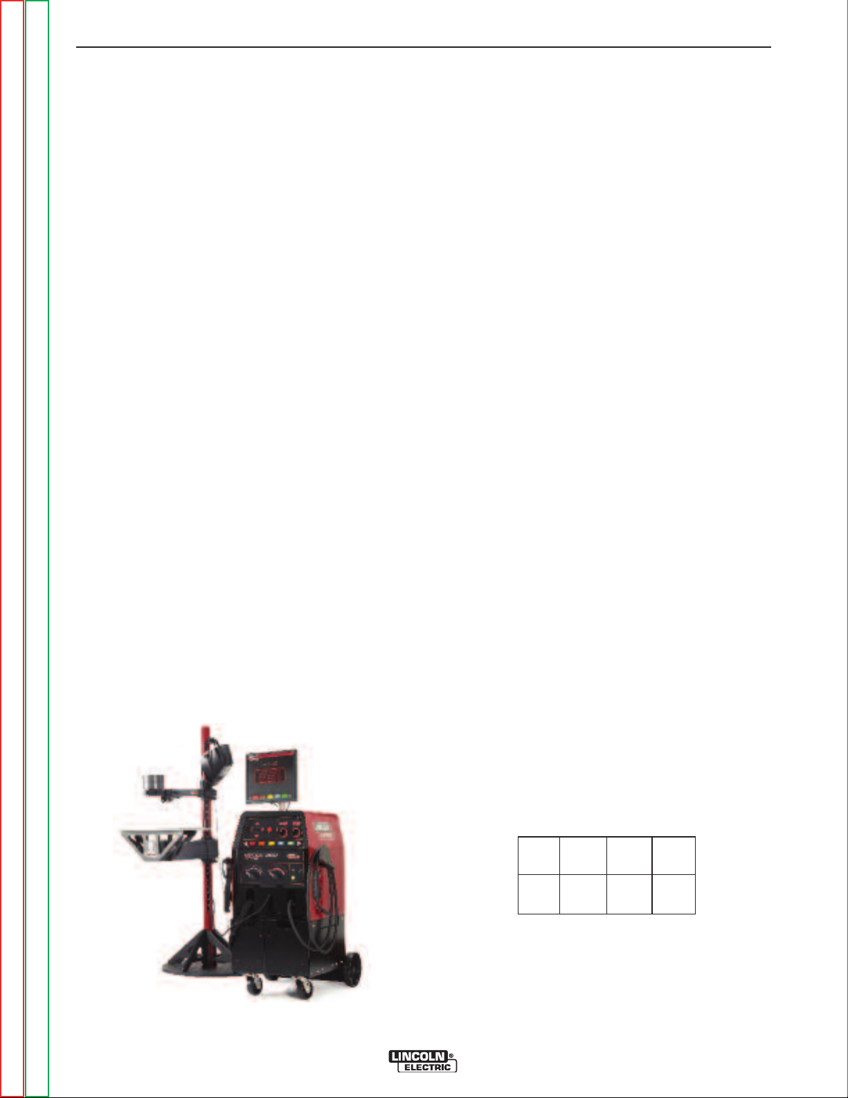
GENERAL DESCRIPTION
The VRTEXTM360 is a Virtual Welding Training
System. This computer controlled interactive system
simulates arc welding through the use of realistic puddle graphics and sounds. This training system is capable of simulating multiple arc welding processes on a
wide variety of weld joint configurations. The VRTEX
360 represents the next generation of Virtual Reality
(VR) welding training.
DESIGN FEATURES
HARDWARE OVERVIEW:
• Virtual Welding Machine, including:
o Monitor
o Coupon Drawer (back drawer)
o VR GMAW/FCAW Gun
o VR SMAW device
o VR GMAW/FCAW Gun holder
o VR SMAW device holder
o VR Helmet w/Face Mounted Display (FMD)
o Five VR Coupons - Flat Plate
Tee Joint
Groove Joint
2” Pipe XXS
6” Pipe Schedule 40
INSTALLATION
TOOLS NEEDED
3/8” Wrench
3/16” Allen Wrench
Phillips Screwdriver
1. Decide on a location for your unit.
NOTE: The unit will take up approximately 8’ L x 8’
TM
For best results, do not install VRTEX
machine in the welding lab. Electrical
interference from power lines, though generally small, can be present. Therefore all
electrical power or lighting wiring within 50
feet of the welding area shall be enclosed
in grounded rigid metallic conduit. In the
event the VRTEX
ference, it is the user's responsibility to
take steps to isolate and/or eliminate the
interference.
D x 8’ H. Keep approximately 3 feet in all
directions of both the stand and VR weld
machine free from obstruction. In addition,
be conscious of where you are placing the
unit to avoid magnetic fields, conductive,
and high frequency objects and processes.
Having these types of objects in the area
can cause interference and result in
increased jitter and/or distortion in the
motion tracking.
TM
360
TM
360 is affected by inter-
• Stand, including:
o Post
o Arm
o Table
o Pins
o Base
o Weights
HARDWARE UNCRATING:
An uninterruptible power supply (UPS)
may be required for the protection of the
system from power irregularities or disruption.
MULTIPLE SYSTEM INSTALLATIONS
If multiple units are required to operate together a
unique frequency transmitter can be installed during
the manufacturing process at Lincoln Electric to reduce
potential interference between systems. AD1332-1
systems have a standard frequency source installed.
AD1332-2 systems have an alternate frequency
source installed. For multiple system installations,
alternate the -1 and -2 systems for best operation:
For Example: If 8 systems are to be installed in the VR
welding lab, the standard and alternate frequencies
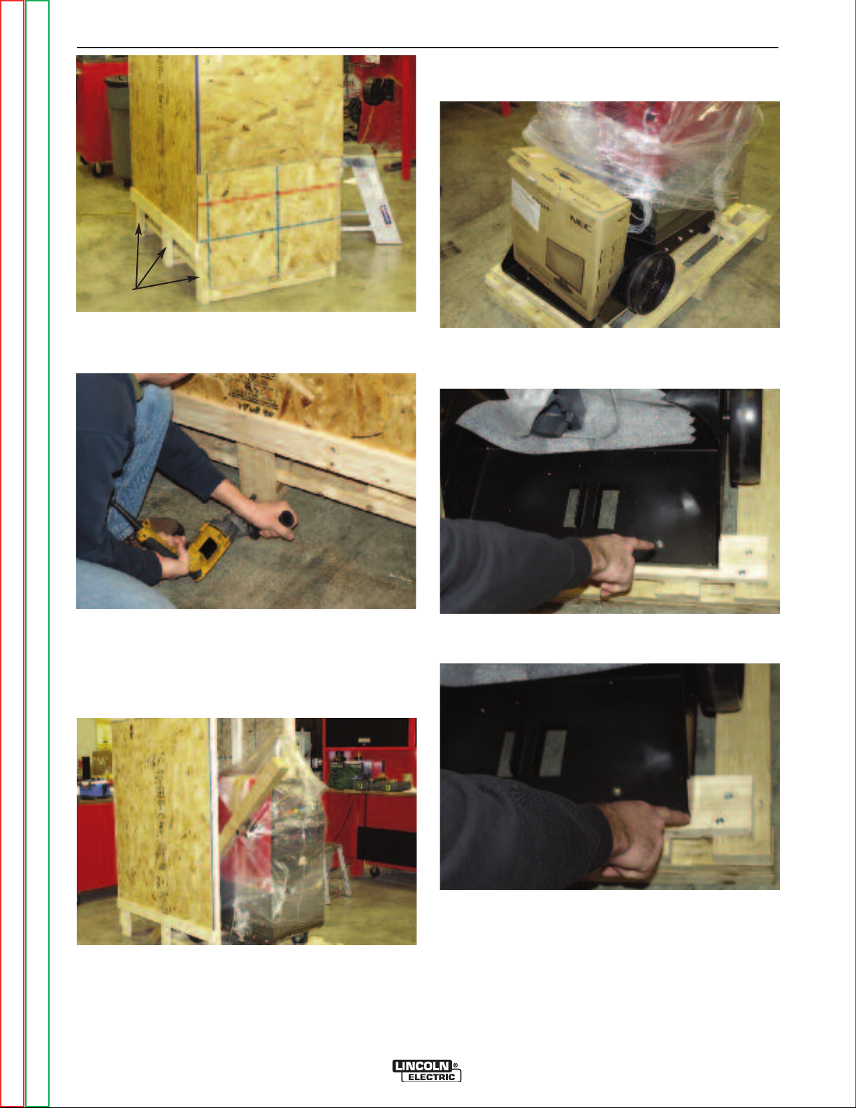
2. Using the 3/8” wrench, remove the screws from the
upper and lower front panels on the shipping crate.
Return to Master TOC Return to Master TOC Return to Master TOC Return to Master TOC
Return to Section TOC Return to Section TOC Return to Section TOC Return to Section TOC
NOTE: The rear of the crate is nailed on. Do not
remove at this time.
VRTEX TM360
Page 15
A-6 A-6
INSTALLATION
8. Remove the monitor from the back of the machine.
FRONT
(upper)
FRONT
(lower)
BOLTS
3. Remove the six 3/8” bolts (three on each side) from
the bottom of the crate assembly.
9. Using the 3/8” wrench, remove the two screws from
the rear base securing the unit to the wooden crate.
Return to Section TOC Return to Section TOC Return to Section TOC Return to Section TOC
4. Carefully slide the crate assembly from the
VRTEXTM360.
5. Slide towards the rear of the machine. Be careful to
avoid damaging the welding device holders located
on each side of the machine.
6. Carefully remove the post (long rectangular
shaped cardboard box) from the crate.
7. Carefully cut and remove plastic wrapping.
Return to Master TOC Return to Master TOC Return to Master TOC Return to Master TOC
10. Remove the four screws from the wooden rear
cross brace.
11. Remove the wooden cross brace while ensuring
the unit is steady and secure.
12. Carefully roll the machine off the rear of the skid.
Ramping may be required.
13. Uncrate and unpack the table and table base.
VRTEX TM360
Page 16

A-7 A-7
INSTALLATION
4. Obtain the three post collar pins from the factory
packaging of the VRTEXTM360.
14. Insert the input supply power cord into the back of
the VRTEX
outlet capable of 115 to 230 VAC at 4 to 2 Amps.
TM
360 and into a standard electrical
TABLE & SWING ARM SET-UP:
1. Using the 3/16” allen wrench, remove the two ¼” x
20 Allen-head screws from the base assembly.
NOTE: The longer screw is in the top.
Swing Arm
Table
5. Insert one of the collar pins into the post at the #6
location.
6. From the top, slide the table onto the post letting it
rest on the collar pin inserted in previous step.
7. Insert the second collar pin into the post at the #13
position.
TM
8. Obtain swing-arm from the rear of the VRTEX
by removing the cable ties from the swing arm and
cable. Grey cable should remain connected to the
VRTEX
TM
360 (DO NOT CUT!).
360
Post
T Pin
Collar
Pins
Return to Section TOC Return to Section TOC Return to Section TOC Return to Section TOC
Cable Tie
Grey Cable
(DO NOT CUT)
2. Insert red post into base assembly aligning the flat
on the pole with the hole.
NOTE: The post will only insert one way.
3. Using the 3/16” allen wrench, secure the post into
position and tighten.
Return to Master TOC Return to Master TOC Return to Master TOC Return to Master TOC
VRTEX TM360
Page 17

A-8 A-8
INSTALLATION
9. Carefully slide swing-arm onto post with the letters
(on the collar) “ABC” up and the grey cable located
on the bottom of the swing arm assembly.
10. Insert a third collar pin at a convenient height for
holding the helmet.
MONITOR:
1. Remove monitor from cardboard box.
2. Remove the cable ties from monitor cables secured
to the monitor mounting post.
MONITOR (Mounting Screws)
Screws
TRACKING SYSTEM FUNDAMENTALS:
The magnetic tracking system is composed of the
following:
• Control Unit (Inside VR Machine)
o Contains the hardware and software neces-
sary to compute position and orientation.
• Source (part of the Swing Arm)
o The source contains electromagnetic coils
enclosed in a plastic shell that emit a magnetic
field. The source is the systemʼs reference
frame for sensor measurements.
• Sensor (in the VR GMAW/FCAW gun, VR SMAW
device, and helmet)
o The sensor contains electromagnetic coils
enclosed in a plastic shell that detect the magnetic fields emitted by the source. The sensorʼs
position and orientation are precisely measured as it moves in reference to the source.
The sensor is completely passive, having no
active voltage applied to it.
Input
VGA
Power
3. Using a Phillips-head screwdriver, carefully mount
the monitor onto the mounting post bracket. Tighten
the four Phillips-head screws securely.
4. Install input power cable and VGA cable into the
monitor.
ADDITIONAL FEATURES:
1. The welding coupons are stored in the coupon
drawer in the rear of the machine.
2. The weld simulation can be displayed on an external monitor or projector by using the SVGA output
on the back of the machine. The external display
must support 1024x780 resolution.
3. External speakers may be connected using the
audio jack located on the back of the machine.
Return to Section TOC Return to Section TOC Return to Section TOC Return to Section TOC
Return to Master TOC Return to Master TOC Return to Master TOC Return to Master TOC
VRTEX TM360
Page 18

A-9 A-9
NOTES
Return to Section TOC Return to Section TOC Return to Section TOC Return to Section TOC
Return to Master TOC Return to Master TOC Return to Master TOC Return to Master TOC
VRTEX TM360
Page 19

B-1 B-1
Operation . . . . . . . . . . . . . . . . . . . . . . . . . . . . . . . . . . . . . . . . . . . . . . . . . . . . . . . . . . . . . B-1
TABLE OF CONTENTS - OPERATION SECTION
Product Description ...............................................................................................B-2
User Interface Overview ........................................................................................B-3
Hardware Specifications .................................................................................B-4/B-5
Powering Up ..........................................................................................................B-7
Login Screen...................................................................................................B-7/B-8
Joint Configuration.................................................................................................B-9
Process Selection ................................................................................................B-10
Stand Set-up........................................................................................................B-10
VR Coupons ........................................................................................................B-10
Table/Arm Rotation...............................................................................................B-11
Environment.........................................................................................................B-12
VR Gas Set-up ....................................................................................................B-12
Weld Machine Settings ........................................................................................B-13
Push Buttons........................................................................................................B-14
Welders View .......................................................................................................B-15
Instructors View....................................................................................................B-15
LASER (Live Action Student Evaluation Report) .................................................B-16
Technique Parameters .........................................................................................B-16
Position ................................................................................................................B-17
Work/Travel Angle................................................................................................B-18
Pass Number .......................................................................................................B-19
Timing/Direction/Discontinuities...........................................................................B-19
Instructor Mode....................................................................................................B-20
Updates ...............................................................................................................B-20
TM
Weldometer
Tolerance Editor...................................................................................................B-22
Choosing Tolerance Set-up .................................................................................B-23
Choosing Tolerance To Load ...............................................................................B-23
.......................................................................................................B-21
Return to Master TOC Return to Master TOC Return to Master TOC Return to Master TOC
Tolerances Screen(s) ..................................................................................B-23/B-26
Tolerances Whip & Travel Speed .........................................................................B-27
Default Weld Processes Settings.........................................................................B-28
VRTEX TM360
Page 20
B-2 B-2
1
2
3
6
7
8
10
11
9
6
5
4
12
14
13
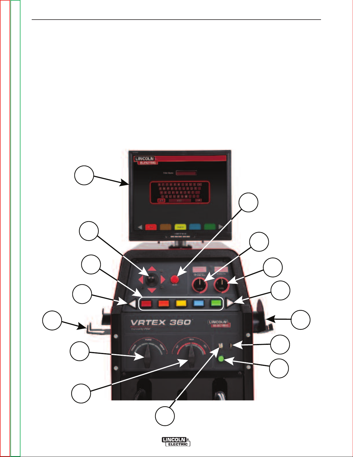
PRODUCT DESCRIPTION
OPERATION
The VRTEXTM360 is a virtual reality arc welding training machine only and NOT a real arc welding machine.
Please be aware of all standard safety practices associated with welding. Some standard warnings are
included in this manual.
If the equipment is used in a manner not specified by
the manufacturer, the protection provided to the equipment and user may be impaired.
FRONT OF MACHINE
Access panels are not to be removed except by qualified service personnel due to risk of electric shock
from accessible live parts.
Return to Section TOC Return to Section TOC Return to Section TOC Return to Section TOC
Return to Master TOC Return to Master TOC Return to Master TOC Return to Master TOC
VRTEX TM360
Page 21

B-3 B-3
OPERATION
USER INTERFACE OVERVIEW
The VRTEXTM360 is a virtual reality arc welding trainer. This computer based training system is an educational tool designed to allow students to practice their
welding technique in a simulated environment. It promotes the efficient transfer of welding skills to the welding booth, while reducing material waste and energy
consumption associated with traditional welding training.
See figure on page B-2 for locations of operator controls and indicators.
1. The monitor allows the student to view the setup
menu selections and also provides an active view of
the actual welding process for teachers and students. The monitor can be rotated for ease of viewing. Make certain the power button on the monitor
is ON and the green LED is lit.
2. By moving the joystick, the operator can navigate
through various menu options.
3. The colored buttons correlate to the colored rec-
tangles present at the bottom of the monitor when
the simulation software is running. These buttons
perform various functions depending upon the command shown in the corresponding box on the
screen.
10. The key switch is located on the lower right of the
control panel. When the system is in the login
screen the instructor may insert a key (shipped
with the system) into the key lock and then rotate it
90 degrees to the right. This will permit access to
the Weldometer
Update screens.
11 Pressing and holding (3 seconds) the green circu-
lar button powers up the VRTEX
Note: It does not power down the system.
12. The red select button accepts (enters) the data
displayed or highlighted on the monitor.
13. VR GMAW/FCAW gun holder.
14. VR SMAW device holder.
TM
, Tolerance Editor, Options and
TM
360 system.
4. The wire feed speed/amperage dial allows the
user to input wire feed speed/amperage.
5. The voltage dial allows the user to input the weld-
ing voltage. This dial also allows input of trim values
when pulse process is in use.
6. The white screen select arrows allow the operator
to cycle through various screens.
7. The process selector switch permits the selection
of welding process. (GMAW, FCAW, OR SMAW)
8. The polarity selector switch permits the selection
of the welding polarity for any given process. (DC+,
DC-, or AC).
9. The USB port is used to upload software and down-
load user data from the software.
Return to Section TOC Return to Section TOC Return to Section TOC Return to Section TOC
Return to Master TOC Return to Master TOC Return to Master TOC Return to Master TOC
VRTEX TM360
Page 22

B-4 B-4
OPERATION
HARDWARE SPECIFICS:
VR GMAW/FCAW GUN
The VR GMAW/FCAW gun should be placed on the
round gun holder on the right side when not in use.
The VR gun has a trigger that is used during the simulation of GMAW and FCAW processes to initiate and
maintain the simulated welding arc.
VR GMAW/FCAW GUN
CAUTION
In order to strike an arc with the VR SMAW device,
strike or tap the tip of the rod (of the VR SMAW device)
on the coupon being welded. To break the arc, move
the VR SMAW device rod away from the work piece.
CAUTION
Do not try to strike the arc with excessive force, as
the arc start is distance based. Excessive force
may result in damage to the VR SMA
The angle of the rod can be changed by squeezing the
clamp of the VR SMA
be moved into the 45 or 90 degree position. Once the
rod is at one of these angles, release the clamp. The
rod should now be fixed in that position. Do not
change the rod angle while the rod is extending or
retracting.
W device. This allows the rod to
VR SMAW DEVICE
W device.
Store gun as shown below to
avoid damage.
VR GMAW/FCAW GUN (Properly Stored)
VR SMAW DEVICE
The VR SMAW device has a rod representing an electrode. This rod retracts when a virtual arc is struck to
simulate the electrode burning off during the virtual
welding process. When the virtual electrode is fully
used up, the rod will stop retracting. When the user
presses “new stick” in the orange actions menu button,
the rod extends out, simulating that a new electrode
was put into the VR SMAW device. When not in use,
the VR SMAW device should be placed in the VR
SMAW holder on the left side of the VR weld machine.
CAUTION
Store device as shown below to
avoid damage.
VR SMAW DEVICE (Properly Stored)
Return to Section TOC Return to Section TOC Return to Section TOC Return to Section TOC
Return to Master TOC Return to Master TOC Return to Master TOC Return to Master TOC
VRTEX TM360
Page 23

B-5 B-5
RATCHET KNOB
HEAD GEAR
FORE / AFT ADJUSTMENT
TILT ADJUSTMENT
CROWN
ADJUSTMENT
PIN HOLES FOR
ADJUSTMENT
OPERATION
Helmet
Users should first adjust the helmet so it fits comfortably. Adjustments can be made by depressing and
turning the knob at the back of the helmet in until the
desired size is achieved. If necessary, the user may
also have to adjust the top crown adjustment to fit their
head size.
HELMET FUNCTIONS
The helmet has an FMD (Face Mounted Display) on
the inside. These FMD lenses display the virtual weld
and environment to the user. The lenses can be shifted left and right to fit comfortably by applying gentle
pressure. In addition, the lenses can be shifted forward and back. The user should make sure the lenses
are parallel to their eyes. Keep the lenses clean at all
times. See Cleaning and Maintenance Section.
HELMET LENSES
Coupon Drawer
The coupon drawer houses the physical coupons.
When not in use, the coupons should be stored there.
To open the drawer, press the top indent down, and
slide the drawer out. Each coupon fits in its own area
defined by the foam locator in the drawer.
COUPON DRAWER
Coupons
The coupons represent the various workpieces that the
user will virtually weld. During the virtual welding
process, they provide physical feedback to the student.
The coupons have been factory calibrated at Lincoln
Electric.
There are five VR Coupons:
1. Flat Plate
2. Tee Joint
3. 3/8” Groove Joint w/Backing Bar
4. 2” Diameter XXS Pipe
5. 6” Diameter Schedule 40 Pipe
Return to Master TOC Return to Master TOC Return to Master TOC Return to Master TOC
Return to Section TOC Return to Section TOC Return to Section TOC Return to Section TOC
LENSES
When not in use, the helmet should be hung from the
stand or placed in the right front drawer to avoid being
damaged.
EAR
BUDS
VRTEX TM360
COUPONS
5
2
4
1
3
Page 24

B-6 B-6
OPERATION
Stand
The stand is comprised of the post, arm, table, collar
pins, base and two weights. Users should position
themselves at the stand during virtual welding.
Post
The arm and table slide up and down and rest on the
collar pins that are inserted into the post. Hole numbers 0 through 28 indicate position of welding for program accuracy. The position is read by identifying the
numbered hole that the pin has been inserted into.
POST W/PIN INSERTED IN #18
SWING ARM ROTATION
POS. A
POS. B
POS. C
Table
The table can be used to gain stability and learn proper body positioning. The base supports the stand and
has weights on the back to maintain stability. The table
can be swung out of the way when not in use.
CAUTION
Do not use the Stand/Table without the base
counter weights properly positioned.
___________________________________________
Coupon Positioning In Swing Arm
The coupons can be inserted into the arm to accommodate flat, horizontal, vertical or overhead welding
positions. The knob on the front of the swing arm can
be pulled out for coupons to be inserted or removed
and pushed in for coupons to be secured. The front of
the swing arm can be rotated down at a 45 or 90degree angle to allow 2G, 5G and 6G pipe welding
positions. The arm can also be rotated around the post
to comfortably accommodate left and right handed
welders or simulate specific welding applications.
COUPON INSERTION / REMOVAL
TABLE ROTATION
Return to Section TOC Return to Section TOC Return to Section TOC Return to Section TOC
CAUTION
Do not use excessive force when inserting and
removing coupons into the arm.
Return to Master TOC Return to Master TOC Return to Master TOC Return to Master TOC
VRTEX TM360
Page 25

B-7 B-7
OPERATION
Powering Up Your System:
1. After you have set up the hardware and have
become familiar with the user controls, you will be
ready to use your system.
2. Plug power cord into a standard outlet.
3. Press and hold the green circular button on the front
panel until it lights up and you hear fans running
inside the machine. (approx. 3 seconds)
GREEN CIRCULAR BUTTON LOCATION
Software will step the user through the following setup
screens:
• Login
• Joint configuration selection
• Process selection
• Stand set up
• Environment
• Gas set up
• Weld machine settings
• Instructorʼs view
• Welderʼs view
• LASER (Live Action Student Evaluation Report)
The key provided with the system allows the user to
access additional information and set-up pages.
• Weldometer
• Tolerance Editor
• Options
• Update
TM
Login Screen:
Overview
This page allows the user to:
Return to Section TOC Return to Section TOC Return to Section TOC Return to Section TOC
4. Your system will start up.
5. Wait a few minutes until your system displays the
login screen on your monitor.
LOGIN SCREEN
When setting up the virtual equipment, the user must
set the welding parameters (e.g. wire feed speed for
VR GMAW) within the ranges set in the tolerance editor. The system ships with Lincoln default tolerances.
Lincoln default tolerances can be reviewed in the tolerance editor, or refer to the Default Weld Process
Settings Chart (if using the default settings) located in
this manual. The WPSʼs are also available on
www.VRTEX360.com. However, users can set and
use their own tolerances for teaching beginner
welders. The tolerances also determine how the user
is scored on such parameters as work angle, travel
angle, travel speed, position, and contact tip to work
distance or arc length.
Return to Master TOC Return to Master TOC Return to Master TOC Return to Master TOC
• Enter Username
• Select Language Preference
• Select Imperial or Metric Units
• Shutdown System
• Continue to the next Setup Screen
1. On Screen Keyboard
The user enters their name by using the joystick and
red select button on the VR weld machine. The joystick allows the user to navigate the keyboard graphic
to highlight letters. Pressing the red select button
enters the letter highlighted into the enter name box as
indicated. The virtual keyboard starts with shift
enabled, so the first letter is automatically capitalized.
The user can select shift or lock (equivalent to caps
lock on a standard keyboard) at any time. If the user
makes a mistake, they can select the back arrow to
delete the last character entered. Once the user
enters their name, they should press the green panel
button to continue.
VRTEX TM360
Page 26

B-8 B-8
Imperial
Metr ic
Abbreviation
Detail
Abbreviation
Detail
Coupon thickness
in
inches
mm
millimeters
Gas flow rate
CFH
cubic feet per hour
LPM
liters per minute
Wire feed speed
IPM
inches p er m inu te
MPM
meters per minute
Weldometer - Base metal
lbs kg
kilog rams
Weldometer - Gas
CF
cubic feet
L
liters
Weldometer -Consumables
lbs
pounds
kg
kilog rams
TM
TM
pounds
T
M
OPERATION
2. Language
Selecting the yellow language menu button brings up
the list of languages the software supports. Use the
joystick to highlight the desired language. Press the
red select button to accept. Press the yellow button
again to exit the language menu. The system stores
the language selection and will automatically start up in
the same language the next time.
3. Measurement Units
The blue unit menu button brings up the measurement
system. Use the joystick to highlight the desired unit of
measurement. Press the red select button to accept.
Press the blue again to exit the measurement unit
menu. Selecting Metric or Imperial converts the user
interface into the corresponding measurement system.
The system stores the measurement selection, so it
will automatically start up in the same unit of measurement the next time. The system uses the units shown
in the table below.
4. Menu
The red menu button allows the student to shut down
the system. If the user selects shutdown, a submenu
appears asking the user if they are sure that they want
to shut down the system. This prompt prevents the
user from accidentally shutting down the system. If the
Return to Section TOC Return to Section TOC Return to Section TOC Return to Section TOC
user selects “Yes”, the VRTEX
Return to Master TOC Return to Master TOC Return to Master TOC Return to Master TOC
TM
360 will shut down.
VRTEX TM360
Page 27
B-9 B-9
GMAW
SMAW
FCAW
Thickness
(in)
Thickness
(mm)
Short Arc
Axial
Spr ay
Pulse
STT
E7 018
E6 010
Gas
Shielded
Self
Shielded
1/4
6
1/8
3
1/4
6
3/8
10
1/4
6
3/8
10
1/8
3
1/4
6
3/8
10
3/8
10
3/8
10
3/8
10
3/8
10
2" X XS
50
6" Sch 40
150
2" X XS
50
6" Sch 40
150
2" X XS
50
6" Sch 40
150
Position
Flat
2F
3F UP
3F DOWN
4F
1G
2G
3G
4G
2G
5G
6G
Plate
Pipe
X
X
X
X
X
X
X
X
X
X
X
X
X
X
XX
X
X
XX
X
X
X
X
X
X
X
X
X
X
X
X
X
X
X
X
X
X
X
X
X
X
X
X
X
X
X
X
X
X
X
X
X
X
X
X
X
X
X
X
X
X
X
X
OPERATION
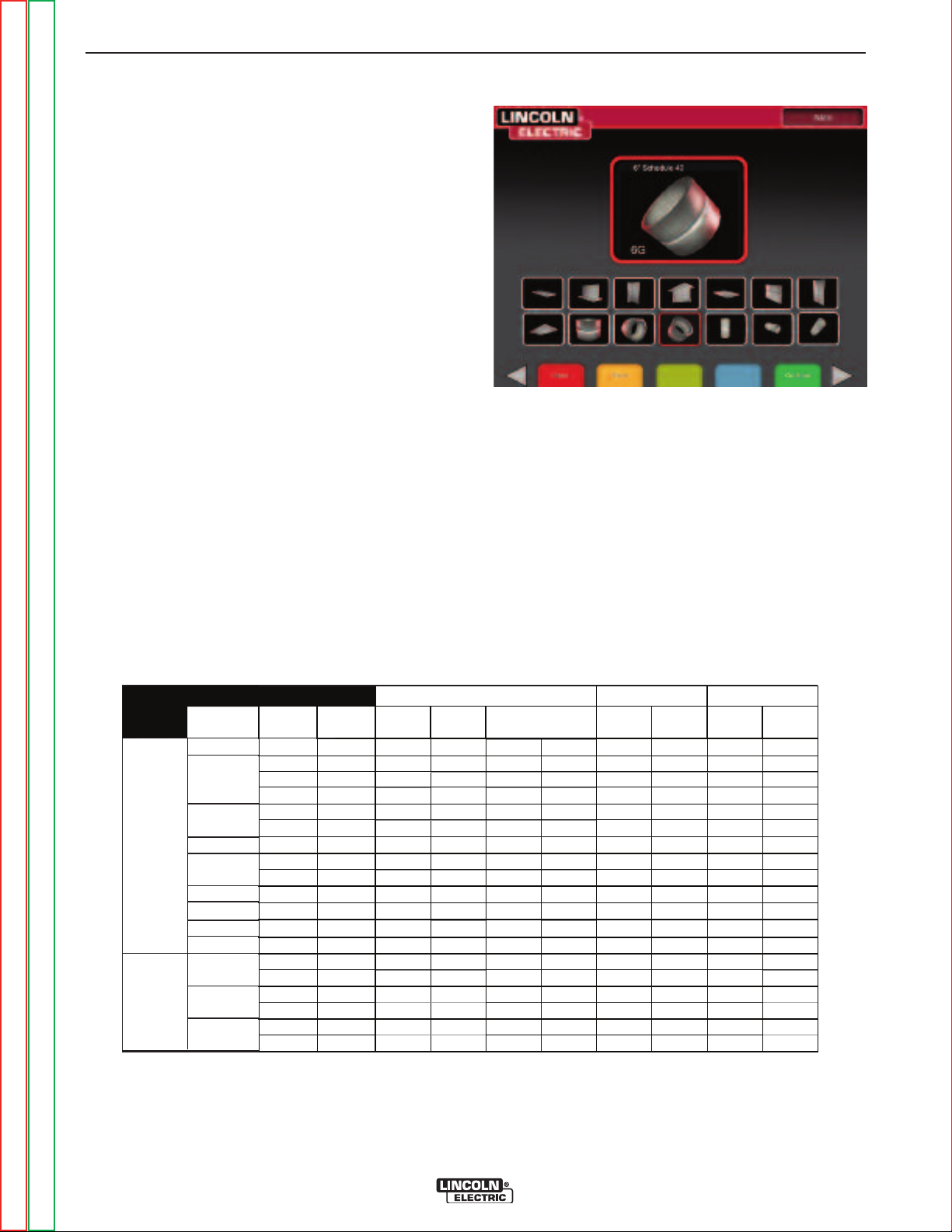
Joint Configuration Selection
Screen:
Overview
The user selects which joint configuration they want to
virtually weld. First, the user selects the joint and position. Using the joystick and the red select button, the
user can highlight and select the joint type and position
in which to weld. A rotating view of the highlighted
coupon shows in the upper area. For some configurations, the user will be given the choice of material
thicknesses to choose from. The user selects material
thickness by using the joystick and red select button.
See table below for supported joint configurations.
JOINT CONFIGURATION SELECTION SCREEN
Menu
Selecting Logout brings the user to the login screen,
with the userʼs name removed.
Back
Selecting Back takes the user back to the previous
screen.
Return to Section TOC Return to Section TOC Return to Section TOC Return to Section TOC
Return to Master TOC Return to Master TOC Return to Master TOC Return to Master TOC
JOINT CONFIGURATION CHART - MILD STEEL
VRTEX TM360
Page 28

B-10 B-10
OPERATION
Process Selection Screen:
Overview
This screen allows the user to select the welding
processes. To change among VR GMAW, VR FCAW,
and VR SMAW, the user moves the process switch on
the front of the weld machine. See the joint configuration chart for available processes. If a process is not
supported for the selected material/thickness, it is
greyed out on this screen and cannot be selected. To
choose among different sub-processes, use the joystick and red select button or green continue button.
At the top of the screen, the user can see the coupon
position and thickness selected. As the user continues
to set up the simulation, additional information will be
added to the right of this readout, so that the user can
reference what has previously been selected.
PROCESS SELECTION SCREEN
Stand Set-Up Screen:
Overview
The correct VR stand information must be put into
the software for the VRTEXTMto operate properly in
all virtual welding applications.
STAND SET-UP SCREEN
Coupon Insertion
Insert one of the VR coupons into the desired position
in the physical VR stand. Make sure the coupon is
seated into the track and then lock the coupon in place
by pushing in the knob at the end of the arm. To
release, pull the knob into the unlocked position and
remove the coupon. When the system is in use, the
coupon should always be locked in place to assure
system accuracy.
Return to Section TOC Return to Section TOC Return to Section TOC Return to Section TOC
VR COUPON (UNLOCKED POSITION)
Menu
Selecting Logout brings the user back to the login
screen, with the userʼs name removed.
Change Coupon Type
Selecting Change Coupon Type goes back to the
configuration selection screen.
Back
Selecting Back takes the user to the previous screen.
Return to Master TOC Return to Master TOC Return to Master TOC Return to Master TOC
VRTEX TM360
Page 29

B-11 B-11
OPERATION
Table/Arm Rotation
Move the physical VR table and arm to the desired
location for the position and joint configuration selected. To raise or lower the arm or table, hold the
arm/table in place and pull out the pin in the pole supporting it. Replace the pin in the hole that supports the
arm/table at the proper height and rest the arm/table
on the pin. If the table is not needed, swing the table
to the left and out of the way. The arm can also be
rotated to the left (A), center (B) or right (C) of the
table.
SWING ARM ROTATION
POS. A
POS. B
POS. C
Pin Positions
When the physical stand is in the desired position, proceed with the following: Use the joystick and red select
button to enter the numbers that appear next to the pin
positions for the table and arm height, into the stand
setup screen. The image on the right side of the stand
setup screen moves to match the selections entered
on the left. If the table is in the “away” position, enter
a table height value of 0. Next, enter the arm rotation
position A (left), B (center), C (right). The arm position
letter aligns with the vertical pin number sticker. An
arm height of 18 and and arm rotation of A is shown in
the picture below.
PIN POSITIONS 18 A
TABLE ROTATION
Note: If the table height indicator in the software
cannot be moved to the pin height indicated
on the post, move the arm height indicator
in the software to a higher position and try
again. See Troubleshooting Guide if necessary.
Return to Section TOC Return to Section TOC Return to Section TOC Return to Section TOC
Return to Master TOC Return to Master TOC Return to Master TOC Return to Master TOC
VRTEX TM360
Page 30

B-12 B-12
Indicate the coupon orientation used on the physical
stand in the coupon rotation area of the stand setup
screen. The red arrow indicates which side of the
coupon that the weld will be made. For pipe configurations, the coupon rotation is replaced with arm angle.
The arm angle can be adjusted by removing the pin at
the end of the arm, rotating the arm to 45 or 90
degrees from its original location, and reinserting the
pin. This is only used to accommodate 2G, 5G & 6G
pipe welding.
STAND SET-UP SCREEN (PIPE)
OPERATION
ENVIRONMENT SCREEN
Menu
Selecting Logout takes the user back to the login
screen, with the userʼs name removed.
Back
Selecting Back takes the user to the previous screen.
Gas Set-Up Screen:
Overview
On this screen, the user selects the gas mixture and
The physical stand should match the stand image
when these selections are completed. To continue,
press the green continue button. The stand setup verification screen will be displayed. This screen serves as
a reminder to make sure VR stand components match
the screen. When verified, press the green continue
button again.
STAND SET-UP SCREEN OVERLAY
gas flow rate. The user must enter the correct gas mixture and flow rate according to the tolerance editor. If
the user does not enter acceptable values, they will be
notified on a later screen and may have to go back and
change their selection on this screen.
To select the gas mixture, use the joystick and the red
select button. The available gas mixtures are shown
on the gas set-up screen below.
To select the gas flow rate, use the joystick. Press the
red select button or green continue button to proceed.
Return to Section TOC Return to Section TOC Return to Section TOC Return to Section TOC
Back
Selecting Back takes the user to the previous screen.
Environment Screen:
Overview
The VRTEXTM360 comes pre-configured with a number of different virtual welding environments. To select
an environment, the user moves the joystick left or
right and then presses the red select button or green
continue button to choose the environment.
Return to Master TOC Return to Master TOC Return to Master TOC Return to Master TOC
GAS SET-UP SCREEN
Menu
Selecting Logout takes the user back to the login
screen, with the userʼs name removed.
Back
Selecting Back takes the user to the previous screen.
VRTEX TM360
Page 31

B-13 B-13
OPERATION
Weld Machine Settings Screen:
Overview
The user must enter the proper welding procedure
and process settings, including wire feed speed,
amperage, voltage, and polarity, where applicable. As
in the gas setup screen, the user must enter values
within the acceptable range as governed by the tolerance editor. If not, they will be notified when the
green check settings button is pressed by the incorrect weld setting screen.
The user changes the wire feed speed or amperage
by rotating the wire feed speed/amperage dial. The
display above the dial indicates the setting.
The user changes the voltage by rotating the voltage
dial. The display above the dial indicates the setting.
Some processes may not allow the user to pre-set the
voltage, in which case the display will be blank.
WELD MACHINE SETTINGS SCREEN
Once the user has set the welding parameters, they
should press the green check settings button. If the
user has entered any settings outside the acceptable
range specified by the settings in the tolerance editor,
the incorrect weld setting screen will appear. The user
will then have to change any settings that are not correct. If the settings are correct and the green check
settings button is pressed, the selected environment
screen will appear on the monitor and in the helmetʼs
stereo visor. The user will then be able to start virtual
welding.
THE INCORRECT WELD SETTINGS SCREEN
Polarity Selector
Change the polarity by rotating the polarity selector
switch. The user can select the following:
• AC
• DC+
• DC-
If default tolerances are being used, refer to the
Default Weld Process Settings included in this
manual.
Menu
Selecting Logout brings the user back to the login
screen, with the userʼs name removed.
Back
Pressing Back goes back to the previous screen.
Virtual Welding Overview
While a user is welding, observers can see the
Welderʼs view, LASER screen, or Instructorʼs view displayed on the monitor. The Welderʼs view shows the
helmets point of view. The LASER screen displays a
real time graph of the weld being made and gives a
score when the user selects “end pass”. The
Instructorʼs view allows another user to zoom in/out
and rotate the coupon to view the weldment from different angles in real time.
Return to Section TOC Return to Section TOC Return to Section TOC Return to Section TOC
Return to Master TOC Return to Master TOC Return to Master TOC Return to Master TOC
VRTEX TM360
Page 32

B-14 B-14
OPERATION
Upper Overlays
The welding technique set in the tolerance editor and
other process details are displayed on the upper right
portion of the screen.
Push Buttons
Menu
Selecting Logout brings the user back to the login
screen, with the userʼs name removed.
Action Button
The orange action menu button has the following
options:
• Clean
• Trim
• Quench
• New Stick
These options are only available when applicable to
the welding process.
Clean removes the weld slag. Trim cuts back the VR
GMAW or VR FCAW wire. Quench simulates quickly
cooling the metal. New Stick extends the rod stick out
to a fixed length on the VR SMAW device to simulate
replacing the consumed rod.
Visual Cues
The yellow visual cues menu button has the following
options:
• “Cheater” Lens – Off 1.25X, 1.5X, 1.75X, 2X
• Travel Speed Visual Cue
• CTWD (Contact To Work Distance) Visual Cue
• Arc Length Visual Cue
• Travel/Work Angles Visual Cue
Visual cues are aids to help users learn faster. The
travel speed, CTWD, arc length, and travel/work angle
cues indicate whether the user is within the tolerances
set in the tolerances editor. Generally, these cues are
color coded as well as symbolic. When cues are red,
they indicate being out of tolerance. Yellow cues indicate close to tolerance, but not optimal. Green cues
indicate being within tolerance and close to optimal.
The “Cheater” Lens magnifies the image as seen by
the user in the helmet and in the welderʼs view. The
user can toggle between 1.25X, 1.5X, 1.75X, 2X select
their option with the red select button.
Travel Speed turns on the travel speed visual cue.
This cue is located on the side of the VR
GMAW/FCAW Gun or VR SMAW device. This cue
uses the color coding position to indicate travel speed.
Note: The goal is to get the arrow pointing up while
keeping it green.
TRAVEL SPEED VISUAL CUE
The CTWD (Contact To Work Distance) cue is only
available for processes using the VR GMAW and VR
FCAW gun. This cue uses color and position to indicate
proper CTWD. The goal is to get the tip of the green
arrow on the line of the “H” bar and keep the arrow
color green.
Return to Section TOC Return to Section TOC Return to Section TOC Return to Section TOC
Return to Master TOC Return to Master TOC Return to Master TOC Return to Master TOC
VRTEX TM360
Page 33

B-15 B-15
OPERATION
CTWD (Contact To Work Distance)
The Arc Length cue is similar to the CTWD cue but
represents arc length distance for the VR SMAW
process. The goal is to get the tip of the arrow on the
line and keep the arrow color Green.
The Travel/Work Angles can be used with the SMAW,
GMAW or FCAW processes. The goal of this cue is to
center the circle in the cross hair and keep the color
green.
TRAVEL/WORK ANGLE
Welder’s View screen
Overview
This screen shows the virtual view as seen by the user
wearing the helmet.
Instructor’s View screen
Overview
This screen shows the coupon and virtual weld in real
time. An observer can rotate and/or zoom in or out on
the coupon in real time. This view also shows the VR
GMAW/FCAW gun or VR SMAW device being used.
Move the joystick to rotate the coupon. Press the red
select button to toggle the joystick from rotate to zoom.
NOTE: Changing views on the monitor does not
change the user’s view in the helmet.
INSTRUCTORS VIEW (POOR WELD)
Return to Section TOC Return to Section TOC Return to Section TOC Return to Section TOC
New Coupon
Pressing the blue new coupon menu button instantly
replaces the current coupon with a fresh, unwelded
coupon. Note that this is a quick way to start over on
the same configuration and process but that it will
remove all passes from the coupon and the graphs on
the LASER screen.
White Screen Select Arrows
Used to rotate through the LASER screen, instructorʼs
view and welderʼs view.
Return to Master TOC Return to Master TOC Return to Master TOC Return to Master TOC
VRTEX TM360
Page 34

B-16 B-16
WELD TECHNIQUE
GRAPH
DISCONTINUITY
INDICATOR
OPERATION
LASER SCREEN
(Live Action Student Evaluation Report)
Overview
This screen summarizes the students welding performance. Detailed information about the students welding technique for each pass are displayed on this
screen.
LASER SCREEN (GOOD WELD)
LASER SCREEN (HORIZONTAL WELDING)
NO WELD
LASER SCREEN
(GRAPH, DEFECTS, DISCONTINUITIES, ETC.)
Technique Parameters
The upper left area of the screen shows the technique
parameters being tracked. The graph of these parameters is located to the right. When the user welds,
each parameter is graphed. The technique parameter
lines are color coded. For example, “position” is written in the blue box and indicated by the blue line. The
left side of the graph represents the left side of the
coupon, and the right side represents the right side of
the coupon. For vertical welds, the graph is rotated so
that it is vertical, with the bottom representing the bottom of the coupon and the top representing the top of
the coupon. The graph also shows how close the parameter was to the ideal value. The ideal value is indicated by the red line located in the center of the graph.
This value is determined by the tolerance editor settings. The upper and lower white lines represent the
acceptable maximum and minimum values that the
parameter should be within. These values are also
determined by the tolerance editor setting. Anything
above the top white line or below the bottom white line
is out of tolerance. The closer the user is to the ideal
line, the better the weld.
Return to Section TOC Return to Section TOC Return to Section TOC Return to Section TOC
Return to Master TOC Return to Master TOC Return to Master TOC Return to Master TOC
LASER SCREEN (VERTICAL WELDING)
NO WELD
VRTEX TM360
Page 35

B-17 B-17
Stringer
Whip
Weave
Pa rameter
GMAW or
FC AW
SMAW
SMAW
GMAW or
FC AW
SMAW
Position
X
X X X X
CTW D X X
Arc Length
X X X
Wor k Angle
X
X X X X
Travel Angle
X
X X X X
Travel Speed
X
X
Dime Spacing
X
Whip Time
X
Puddle Time
X
Width of Weave
X
X
Weave Timing
X
X
Weave Sp acing
X X
6010 Only
Each parameter can be toggled on or off of the graph by highlighting the parameter with the joystick and pressing
the red select button. Whipping and weaving parameters are graphed when the user uses these welding techniques. The following technique parameters are used in the following situations:
OPERATION
Position is the userʼs ideal weld root location. This location can change with each pass. When weaving, the ideal
location is considered the centerline of the weave.
Contact tip to work distance (CTWD) (for VR GMAW and VR FCAW) and arc length (for VR SMAW) are the distances from the tip of the VR GMAW/FCAW gun or VR SMAW device to a plane going through the ideal position
location.
Return to Master TOC Return to Master TOC Return to Master TOC Return to Master TOC
Return to Section TOC Return to Section TOC Return to Section TOC Return to Section TOC
VRTEX TM360
Page 36

B-18 B-18
Work Angle is the angle between the electrode and workpiece as seen in the work angle picture.
OPERATION
Travel Angle is the angle between the electrode and the workpiece in the direction of travel. The upper right area
of the screen displays if the user should be pushing or dragging. If the user pushes when they should be dragging, they will not receive maximum points. For pipe welding, this is the angle between the electrode and the tangent of the pipe at that point.
Return to Section TOC Return to Section TOC Return to Section TOC Return to Section TOC
Return to Master TOC Return to Master TOC Return to Master TOC Return to Master TOC
VRTEX TM360
Page 37

B-19 B-19
OPERATION
Travel Speed is how fast the electrode is traveling in
respect to the workpiece.
Dime Spacing is the distance from one solidified weld
puddle to the next. (whip technique only)
Whip Time is the time the user is in the whipping
motion, or not dwelling in the weld puddle. (whip technique only)
Dwell Time is the time the user is dwelling, or keeping
the VR Stick electrode in the virtual puddle. (whip
technique only)
Width of Weave is the side-to-side distance of where
the VR GMAW/FCAW gun or VR SMAW device was
aimed when completing one weave cycle in a series
that make up a weld.
Weave Timing is the time taken to complete one side
to side weaving motion.
Weave Spacing is the distance in the overall direction
of travel between one weave cycle in a series that
make up a weld.
Bead Render
An image of the completed pass appears in the middle
of the screen.
Discontinuity Indicator
The lower left side of the screen list potential discontinuities. When a student uses incorrect welding techniques, this causes specific weld discontinuities. A line
is drawn at the location indicating these discontinuities.
For example, too long an arc length will cause porosity.
Potential discontinuities include:
• Incomplete Fusion/Penetration
• Slag Inclusion
• Porosity
• Undercut
• Poor Bead Placement
• Wrong Weld Size
• Convex/Excessive Reinforcement
• Concave/Underfill
• Excess Spatter
• Melt Through/Blow Through
Pass number
The pass number is displayed on the left center of the
screen. To change the pass being viewed, use the joystick to highlight the pass number and then joystick left
or right to change the pass number. For pipe, the information is displayed in a similar manner on a 2D screen
as though the pipe is unraveled and put on a flat surface. The user can choose between viewing the whole
pipe or one of the four quadrants of the pipe. Use the
joystick to highlight the pipe section desired.
Travel Direction
The travel direction is located on the right side in the
middle of the screen. When the user first starts to
weld, a travel direction is sensed by the system and an
arrow indicating the direction is displayed. For visual
cues, the system assumes these directions. The visual cues will automatically adapt to the travel direction
used when the arc is struck.
Return to Section TOC Return to Section TOC Return to Section TOC Return to Section TOC
Return to Master TOC Return to Master TOC Return to Master TOC Return to Master TOC
VRTEX TM360
Page 38

B-20 B-20
OPERATION
End Pass
When the user presses the green “End Pass” menu
button, the pass is scored, a snapshot of the weld is
taken, and the percentages of the weld containing discontinuities are calculated. If the user has inserted a
USB device, pressing “End Pass” also automatically saves a student report to the USB memory
device at the front of the weld machine. Allow 10
seconds after pressing the “End Pass” button to allow
time for the file to be saved. Student reports are not
saved internally on the VRTEX
saved on the USB device at the time of the weld, and
another weld is made, the previous weld data will be
lost.
TM
360. If the file is not
Score
On the upper right of the screen, a score for each parameter is calculated. The closer each parameter is to
the ideal value, the higher the score will be (out of
100). The total score at the bottom of the scoring section is calculated as an average of each parameter. To
achieve the maximum score, the weld must be made
on the entire length of the coupon.
Student Report
The student report is a PDF file that captures the
graph, discontinuities, bead render, score and other
information about the weld. This PDF can be printed
or archived from another computer to track student
progress.
Peak and Background Current
These welding parameters are shown on the LASER
screen when the student is using the STT welding
process. These settings cannot be modified but are
indicated on the system to allow the student to become
familiar with the terms.
Instructor Mode
Overview
The Instructor Mode give users the option of viewing
the WeldometerTMusing the tolerance editor and setting
other preferences. In order to access instructor mode,
the user must first go back to the login screen. This
can be done on most screens by pressing menu,
logout, and selecting yes. Then the user must place
the key into the turn key slot at the front of the weld
machine and rotate the key 90 degrees to the right.
Turning the key switch again brings the system out of
the instructor mode.
INSTRUCTOR MODE
Options
The options screen in the instructor mode allows the
user to change the volume of the user interface noises and welding sounds. Move the joystick left and
right and then hit the select button to choose the volume. A volume of 0 will mute the sound, while a volume of 10 is the loudest.
Update
Overview
The update screen in the instructor mode allows the
user to update their software or to update specific configuration files from the USB memory device the front
of the weld machine. Clicking on this brings up two
options:
Update Software
Update Configuration File
Software
Selecting this option loads a newer version of the software if one is available on the USB in the front of the
machine. Updating to a different version may shut
down or restart the system.
After updating, the system may need to be shut down
and restarted for changes to take affect.
Configuration File
Selecting this option loads any configuration changes
from the USB in the front of the machine. This is used
for part replacement.
Return to Section TOC Return to Section TOC Return to Section TOC Return to Section TOC
Instructor mode includes the following:
• Options
• Update
• Weldometer
• Tolerances
Return to Master TOC Return to Master TOC Return to Master TOC Return to Master TOC
TM
VRTEX TM360
Page 39

B-21 B-21
OPERATION
Weldometer
TM
Overview
The WeldometerTMtracks virtual consumables, base material and gas usage. This information can be used to track
materials and cost savings created by the use of virtual welding training. The WeldometerTMtracks material usage
and arc time over a “trip” (since last reset) and over the VR systems lifetime.
Arc Time keeps track of the amount of time (hours:min:seconds) students have spent with a virtual arc struck with
each process.
Base Metal tracks how many virtual coupons have been used and their cumulative weight. Note that plate 3/8”
includes groove joints as well as tee joints, while plate 1/4" includes both tee joints and practice plates.
Gas tracks how much virtual gas was used.
Consumables tracks the cumulative weight of each type of virtual consumable used. It also displays how many
virtual SMAW electrodes are used.
At the bottom of the screen, the Simulated Welder Time keeps track of how long the unit has been on (time in
hours:minutes:seconds).
WELDOMETER
TM
Return to Section TOC Return to Section TOC Return to Section TOC Return to Section TOC
Return to Master TOC Return to Master TOC Return to Master TOC Return to Master TOC
VRTEX TM360
Page 40

B-22 B-22
OPERATION
Reset Trip
Pressing Reset Trip zeroes out all items in the trip col-
umn. This allows an instructor to track VR material
savings over a certain time period.
Save to File
If a USB memory device is in the front of the unit,
selecting “save to file” saves a file with all of the current
WeldometerTMinformation. Once the file has saved,
the user can take the USB to a computer or printer to
print, email, copy, store or view the file.
Back
Pressing Back takes the user to the previous screen.
Tolerance Editor
Overview
The tolerance editor allows users to modify the system
default settings to fit their curriculum.
TM
The VRTEX
parameters pre-installed. These default parameters
can be modified by the instructor to reflect a specific
welding application or technique. The welding parameters that can be modified include:
- WFS range
- Voltage range
- Amperage range
- Gas mixture
- Gas flow rate
The technique parameters ideal range values can also
be modified:
- Position
- CTWD/Arc length
- Work angle
- Travel angle
- Travel Speed
360 ships with Lincoln “default” welding
TOLERANCES
CAUTION
Changing the settings in the tolerance editor will
dramatically affect how the system runs. Take care
in changing the settings of the tolerance editor as
not to reflect unrealistic welding situations.
Return to Section TOC Return to Section TOC Return to Section TOC Return to Section TOC
Return to Master TOC Return to Master TOC Return to Master TOC Return to Master TOC
VRTEX TM360
Page 41

B-23 B-23
OPERATION
Choose Tolerance Set-up
This displays the list of all tolerance settings currently
stored on the unit. All units ship with default settings.
If the user presses the red select button while the file
name is highlighted, it becomes the currently used tolerance setting. This affects the visual cues, graphs,
discontinuities and score.
Choose Tolerance to Load
This displays the list of all tolerance sets currently
stored on the USB device. Files can be transferred to
and from a VRTEXTM360 with a USB memory device.
Back
Pressing back returns the system to the login screen.
Edit
This menu button affects the file currently being shown
in the choose tolerance setup window. This menu has
the following options:
• Create New
• Save to File
• Copy
• Delete
• Rename
Pressing Create New creates a new file on the unit.
The file starts with the default settings. Pressing this
button takes the user to a keyboard screen so that a
new file name can be entered.
USB Edit
This menu relates only to the files on the USB memory device. If there is a file name currently listed in the
choose tolerance to load box, pressing the options on
the menu will take action on that file. This menu has
the following options:
• Copy to List
• Delete
• Rename
• Load from USB
Pressing Copy to List copies the file currently being
shown on the choose tolerance to load box and saves
it to the VRTEX
Pressing Delete brings up an “are you sure” dialogue.
Selecting yes deletes the file currently being shown on
the choose tolerance to load. This deletes the file from
the USB memory device. The user can also cancel out
by pressing no or pressing the back button.
Pressing Rename brings the user to a keyboard
screen where the name of the current file can be
changed.
Pressing Load loads the names of the files currently
on the USB memory device. The names show up in
the choose tolerance to load box. The user will need
to select this in order to see what is on their USB memory device.
TM
360.
Pressing Save to File saves the current file to a USB
memory device if inserted in the front of the machine.
Pressing Copy makes a copy of the file currently being
shown on the choose tolerance setup window. The
copy is identified with the same name plus an incremented number after it.
Pressing Delete brings up an “are you sure” dialogue.
Selecting yes deletes the file currently shown. The
user can cancel out by pressing no or pressing the
back button.
Pressing Rename brings the user to a keyboard
screen where the name of the current file can be
changed.
Tolerances Keyboard Screen
Overview
Allows the user to name or rename tolerance files.
TOLERANCES (KEYBOARD SCREEN)
Return to Section TOC Return to Section TOC Return to Section TOC Return to Section TOC
Return to Master TOC Return to Master TOC Return to Master TOC Return to Master TOC
VRTEX TM360
Page 42

B-24 B-24
OPERATION
TOLERANCES SELECTED (LINCOLN DEFAULTS)
Back
Pressing back returns the user to the previous page
screen.
Continue
Pressing continue goes to the tolerance configuration
selection screen, unless the user was renaming a file,
in which case it goes back to the previous page.
Back
Pressing Back goes back to the pervious screen.
Continue
Pressing Continue goes to the tolerance process
selection screen.
Tolerances Process Selection
Screen
Overview
The user selects which process to modify.
TOLERANCES PROCESS SELECTION SCREEN
Tolerances Joint Configuration
Selection Screen
Overview
The user selects which configuration to modify.
TOLERANCE CONFIGURATION SELECTION
Menu
Menu
Selecting Logout and then yes in the submenu brings
the user back to the login screen in welding mode.
Selecting Change Coupon Type takes the user back
to the tolerances configuration selection screen.
Back
Pressing Back goes back to the tolerance configuration selection screen.
Continue
Pressing Continue goes to the tolerance equipment
settings screen.
Return to Section TOC Return to Section TOC Return to Section TOC Return to Section TOC
Selecting Logout and then yes in the submenu takes
the user back to the Login screen.
Selecting Change Process brings the user back to the
tolerances process selection screen.
Return to Master TOC Return to Master TOC Return to Master TOC Return to Master TOC
VRTEX TM360
Page 43

B-25 B-25
OPERATION
Tolerances Value Modifying
Overview
The user can modify the tolerance values. This is done
by: 1) Use the joystick to highlight the equipment setting or parameter to change. 2) Press the red select
button. 3) Use the joystick to change the value.
Pressing the green set tolerances button will save the
changes.
The following screens are used to modify tolerances:
• Tolerances Equipment Settings screen
• Tolerances Gas screen
• Tolerances Welding Technique Parameters screen
• Tolerances Pattern and Aim screen
• Tolerances Whip and Travel Speed screen
• Tolerances Weave screen
Next & Previous
The arrow buttons are used to cycle through the tolerance editor screens.
The configuration and process selected are shown at
the top of the screen.
In the upper right of the screen is the name of the tolerance set being modified.
Ideal values represent the ideal weld technique parameters. If the user welds using the technique listed as
ideal, they will get the best score. The ideal values are
represented by the red line on the LASER screen.
Changing the +/- changes the acceptable tolerance
indicated by the white lines on the LASER screen. Any
welding technique used within that +/- range is acceptable but will be scored lower the further it is from the
ideal value. As an example, a work angle with an ideal
of 45 degrees and a +/-1 of 10 degrees means that the
user can use a work angle between 35 and 55 degrees
and create an acceptable weld.
Settings that are non-applicable to the process selected are greyed out and cannot be changed.
Next Pass
Changes the pass being modified to the next pass in
the series. If this is the last pass, this option will not be
available.
Tolerances Equipment Settings
Screen
TOLERANCES EQUIPMENT SETTINGS SCREEN
Overview
This screen allows for the modification of the following
welding parameters:
• Wire Feed Speed
• Amperage
• Voltage
• Polarity
Tolerances Gas screen
Overview
This screen allows for the modification of:
• Gas Mixture Selected
• Gas Flow Rate
TOLERANCES GAS SCREEN
Return to Section TOC Return to Section TOC Return to Section TOC Return to Section TOC
Menu
This is the same as the tolerance configuration selection screen.
Back
Pressing back goes to the previous screen without
saving changes.
Prev Pass
Pressing this changes the pass being modified. If this
is the first pass, this option is not available. The pass
number currently being modified is shown in the upper
right of the screen.
Return to Master TOC Return to Master TOC Return to Master TOC Return to Master TOC
VRTEX TM360
Page 44

B-26 B-26
Z
Y
X
XX
X
Z
TEE PIPE GROOVE
OPERATION
Tolerances Welding Technique
Parameters Screen
Overview
This screen allow for the modification of:
• CTWD/Arc Length
• Work Angle
• Travel Angle
TOLERANCES WELDING
TECHNIQUE PARAMETERS
Tolerances Pattern and Aim Screen
Overview
This screen allows the user to change the type of pattern being used (stringer, box weave, straight weave,
whip, triangle weave) and the position of the root of the
weld. The X and Y values change the location of
where the weld bead should be placed. This affects
the position parameter on the LASER screen. The +/determines how far off from the ideal position the student can place the electrode before it results in a misplaced weld.
PATTERN & AIM SCREEN
Note: The travel angle for drag welding techniques
should always be less than 90 degrees. The
travel angle for pushing technique should always
be greater than 90 degrees.
COORDINATE CHART FOR WELD PLACEMENT (POSITION)
Return to Section TOC Return to Section TOC Return to Section TOC Return to Section TOC
Return to Master TOC Return to Master TOC Return to Master TOC Return to Master TOC
VRTEX TM360
Page 45

B-27 B-27
OPERATION
Tolerances Whip and Travel Speed
Screen
Overview
This screen allows for the modification of technique
parameter relating to the whipping welding technique
and travel speed including:
• Dime Spacing
• Whip Time
• Puddle Time
• Travel Speed
WHIP & TRAVEL SPEED SCREEN
Tolerances Weave Screen
Overview
This screen allows for the modification of weaving
welding technique including:
• Width of Weave
• Weave Timing
• Weave Spacing
TOLERANCES WEAVE SCREEN
Return to Section TOC Return to Section TOC Return to Section TOC Return to Section TOC
Return to Master TOC Return to Master TOC Return to Master TOC Return to Master TOC
VRTEX TM360
Page 46

B-28 B-28
SMAW 1/8" E6010 Fleetweld 5P+ NA NA Flat .25" 90 (±5) NA DC+
SMAW 1/8" E6010 Fleetweld 5P+ NA NA 2F, 3F up, 4F .375" 90 (±5) NA DC+
SMAW 1/8" E6010 Fleetweld 5P+ NA NA 1G, 2G, 3G up, 4G .375" 90 (±5) NA DC+
SMAW 1/8" E7018 Excalibur 7018 NA NA Flat .25" 125 (±5) NA DC+
SMAW 1/8" E7018 Excalibur 7018 NA NA 2F, 3F up, 4F .375" 125 (±5) NA DC+
SMAW 1/8" E7018 Excalibur 7018 NA NA 1G, 2G, 3G up, 4G .375" 125 (±5) NA DC+
Root: 80 (±5)
Hot:100 ( + 5)
Fill/Cap: 80 (±5)
Root: 80 (±5)
Hot:100 ( + 5)
Fill/Cap: 80 (±5)
Root: 80 (±5)
Hot:100 ( + 5)
Fill/Cap: 80 (±5)
1/8" E6010 Fleetweld 5P+ Root: 90 (±5)
Hot: 100 (±5)
Fill/Cap: 80 ( + 5)
1/8" E6010 Fleetweld 5P+ Root: 90 (±5)
Hot: 100 (±5)
Fill/Cap: 80 ( + 5)
1/8" E6010 Fleetweld 5P+ Root: 90 (±5)
Hot: 100 (±5)
Fill/Cap: 80 ( + 5)
1/8" E6010 Fleetweld 5P+ Root: 90 (±5)
Hot: 100 (±5)
Fill/Cap: 80 ( + 5)
1/8" E6010 Fleetweld 5P+ Root: 90 (±5)
Hot: 100 (±5)
Fill/Cap: 80 ( + 5)
1/8" E6010 Fleetweld 5P+ Root: 90 (±5)
Hot: 100 (±5)
Fill/Cap: 80 ( + 5)
GTAW Root: NA
Fill/Cap: 80 (±5)
GTAW Root: NA
Fill/Cap: 80 (±5)
GTAW Root: NA
Fill/Cap: 80 (±5)
GMAW - S .035" ER70S-6 SuperArc L-56 75A/25C 15 - 35 Flat .25"
250 ( + 5) 18 DC+
GMAW - S .035" ER70S-6 SuperArc L-56 75A/25C 15 - 35 2F, 3F down .125" 250 (+ 5) 18 DC+
GMAW - S .035" ER70S-6 SuperArc L-56 75A/25C 15 - 35 2F .25" 375 (+ 5) 20 DC+
GMAW - S .035" ER70S-6 SuperArc L-56 75A/25C 15 - 35 3F up .25" 275 (+ 5) 18 DC+
GMAW - S .035" ER70S-6 SuperArc L-56 75A/25C 15 - 35 4F .25" 325 (+ 5) 19 DC+
GMAW - S .035" ER70S-6 SuperArc L-56 75A/25C 15 - 35 1G .375" 350 (+ 5) 20 DC+
GMAW - S .035" ER70S-6 SuperArc L-56 75A/25C 15 - 35 2G .375" 320 (+ 5) 19.5 DC+
GMAW - S .035" ER70S-6 SuperArc L-56 75A/25C 15 - 35 3G up .375"
250 ( + 5) 17.9 DC+
GMAW - S .035" ER70S-6 SuperArc L-56 75A/25C 15 - 35 4G .375"
270 ( + 5) 18 DC+
GMAW - Spray .045" ER70S-6 SuperArc L-56 90A/10C 25-40 Flat 0.25
400 ( + 5) 27.1 DC+
GMAW - Spray .045" ER70S-6 SuperArc L-56 90A/10C 25-40 2F .375"
375 ( + 5) 26.5 DC+
GMAW - Spray .045" ER70S-6 SuperArc L-56 90A/10C 25-40 1G .375"
370 ( + 5) 26.5 DC+
GMAW - Pulse .045" ER70S-6 SuperArc L-56 90A/10C 25-40 2G .375"
130 ( + 5) .95(trim) DC+
GMAW - Pulse .045" ER70S-6 SuperArc L-56 90A/10C 25-40 3G up .375"
130 ( + 5) .95(trim) DC+
GMAW - STT .045" ER70S-6 SuperArc L-56 100C 15 - 35 2G Pipe
130 - 150 NA
GMAW - Pulse .045" ER70S-6 SuperArc L-56 90A/10C 25-40 2G Pipe 125-130 .95(trim)
GMAW - STT .045" ER70S-6 SuperArc L-56 100C 15 - 35 5G Pipe down
130 to 150 NA
GMAW - Pulse .045" ER70S-6 SuperArc L-56 90A/10C 25-40 5G Pipe up 125-130 .95(trim)
GMAW - STT .045" ER70S-6 SuperArc L-56 100C 15 - 35 6G Pipe down
130 to 150 NA
GMAW - Pulse .045" ER70S-6 SuperArc L-56 90A/10C 25-40 6G Pipe up 125-130 .95(trim)
FCAW - G .045" E71T-1 UC 71A85 75A/25C 25-50 Flat .25"
275 ( + 5) 25 DC+
FCAW - G .045" E71T-1 UC 71A85 75A/25C 25-50 2F, 3F up, 4F .375"
275 ( + 5) 25 DC+
FCAW - G .045" E71T-1 UC 71A85 75A/25C 25-50 1G, 2G, 3G up, 4G .375"
275 ( + 5) 25 DC+
GMAW - STT .045" ER70S-6 SuperArc L-56 100C 15-35
130 to 150 NA
FCAW - G .045" E71T-1 UC 71A85 75A/25C 25-50
275 ( + 5) 25
GMAW - STT .045" ER70S-6 SuperArc L-56 100C 15-35 5G Pipe down
130 to 150 NA
FCAW - G .045" E71T-1 UC 71A85 75A/25C 25-50 5G Pipe up
275 ( + 5) 25
GMAW - STT .045" ER70S-6 SuperArc L-56 100C 15-35 6G Pipe down
130 to 150 NA
FCAW - G .045" E71T-1 UC 71A85 75A/25C 25-50 6G Pipe up
275 ( + 5) 25
FCAW - S 5/64" E71T-8 NR- 232/233 NA NA Flat .25" 140 20 DCFCAW - S 5/64" E71T-8 NR- 232/233 NA NA 2F, 3F up .375" 155 21 DC-
6"
DC+
DC+
6"
6"
DC+
NA
NA
NA
2"
DC+
DC+
NA
DC+
DC+
NA
NA
DC+
DC+
DC+
DC+
DC+
NA
NA
NA
wfs (ipm) or amps
Voltage
NA
NA
Pol
VRTEX 360 - Default Weld Process Settings
Position
Mat'l (in)
VR Welding
Process
Consumable
Type
Gas Flow
(cfh)
NA
Excalibur 7018
NA
NA
Lincoln Brand
Gas Mixture
Excalibur 7018
NA
6"
Excalibur 7018
NA
Fleetweld 5P+
6"
6G Pipe up
6"
NA
Excalibur 7018
NA
3/32" E7018
SMAW
SMAW
3/32" E7018
3/32" E7018
SMAW
NANASMAW
Excalibur 7018
Excalibur 7018
Excalibur 7018
NA
3/32" E7018
3/32" E7018
3/32" E7018
SMAW
SMAW
3/32" E7018
SMAW
3/32" E7018
6"
5G Pipe up
1/8" E6010
SMAW
6"
2G Pipe
NA
2G Pipe
5G Pipe up
NA
5G Pipe up
6G Pipe up
NA
NA
SMAW
3/32" E7018
Excalibur 7018
NA
6"
DC+6"6"
DC+
DC+
NA
DC+
DC+
NA
DC+
NA
6G Pipe up
2"
2"
2"
SMAW
1/8" E6010
Fleetweld 5P+
NA
NA
2G Pipe
5G Pipe up
2"
2"
6G Pipe up
Fleetweld 5P+
1/8" E6010
SMAW
2G Pipe
NA
NA
Excalibur 7018
NA
SMAW
6"
2G Pipe
NA
NA
FCAW - S 5/64" E71T-8 NR- 232/233 NA NA 1G,2G .375" 130 21 DCFCAW - S 5/64" E71T-8 NR- 232/233 NA NA 3G up .375" 125 19.5 DC-
OPERATION
Return to Master TOC Return to Master TOC Return to Master TOC Return to Master TOC
Return to Section TOC Return to Section TOC Return to Section TOC Return to Section TOC
VRTEX TM360
Page 47

B-29 B-29
NOTES
Return to Section TOC Return to Section TOC Return to Section TOC Return to Section TOC
Return to Master TOC Return to Master TOC Return to Master TOC Return to Master TOC
VRTEX TM360
Page 48

D-1 D-1
Maintenance . . . . . . . . . . . . . . . . . . . . . . . . . . . . . . . . . . . . . . . . . . . . . . . . . . . . . . . . . . . . . . . . . . . . . . . . . . .D-1
Cleaning and Maintenance . . . . . . . . . . . . . . . . . . . . . . . . . . . . . . . . . . . . . . . . . . . . . . . . . . . . . . . . . . . . .D-2
Major Component Location . . . . . . . . . . . . . . . . . . . . . . . . . . . . . . . . . . . . . . . . . . . . . . . . . . . . . . . . . . . . .D-3
TABLE OF CONTENTS - MAINTENANCE SECTION
Return to Master TOC Return to Master TOC Return to Master TOC Return to Master TOC
VRTEX TM360
Page 49

D-2 D-2
MAINTENANCE
CLEANING & MAINTENANCE
FMD
Taking proper care of the FMD (Face Mounted Display)
is important for optimal functioning of the equipment.
Occasionally, the FMD lens should be wiped with the
lint free lens wipe that is provided. This can be done
to remove fingerprints from the lenses. You can also
use a lens cloth (e.g., from a camera shop). Paper
towels or household cloths may scratch or damage the
lenses and should not be used. Avoid exposing the
FMD to liquids. Cleaning solutions should not be used
to clean the FMD. Do not use Isopropyl alcohol or solutions containing alcohol to clean the lenses or plastic
parts on the FMD. You can also use a camera pressure canister to occasionally blow out dirt.
You may want to clean the inside of the helmet occasionally. Be sure to do so without exposing the FMD to
any unacceptable materials, as explained above.
The FMD should be kept in a clean and dry location out
of direct sunlight. Avoid dirty or sandy environments,
as these can lead to scratching of optics and damage
the FMD mechanical adjustments.
Monitor
CAUTION
The monitor is not a touch screen and can be damaged by touching or poking it with any object. Use
care when cleaning screen. Use only a soft dry
cloth (cotton or flannel). Avoid chemicals and solvents (alcohol, benzine, acidic or alcazine solvent
cleaners). Avoid granular or abrasive cleaning
agents.
Return to Section TOC Return to Section TOC Return to Section TOC Return to Section TOC
Return to Master TOC Return to Master TOC Return to Master TOC Return to Master TOC
VRTEX TM360
Page 50

D-3 D-3
11
33
44
77
66
22
55
MAINTENANCE
1. Case Front Assembly
2. Control Panel Assembly
3. Coupon Drawer Assembly
4. Base Assembly & Computer
5. Stand Assembly & Accessories
6. Cart Assembly
7. Covers
FIGURE D.1 - MAJOR COMPONENT LOCATION
Return to Section TOC Return to Section TOC Return to Section TOC Return to Section TOC
Return to Master TOC Return to Master TOC Return to Master TOC Return to Master TOC
VRTEX TM360
Page 51

D-4 D-4
NOTES
Return to Section TOC Return to Section TOC Return to Section TOC Return to Section TOC
Return to Master TOC Return to Master TOC Return to Master TOC Return to Master TOC
VRTEX TM360
Page 52

E-1 E-1
115/240 VAC
50/60 HERTZ
SINGLE PHASE
INPUT
TERMINAL
STRIP
ON
SWITCH
INTERLOCK
RELAY
5 VDC USB
SIGNAL
AUDIO 1
AUDIO
RECEPTACLE
DISPLAY
LED
PC BOARD
INTERFACE
MODULE
DIGITAL
(USB)
V
IDEO
RECEPTACLE
MONITOR VGA
SPLITTER
12 VDC
GREEN LED
12 VDC
SUPPLY
GREEN LED
5 VDC
SUPPLY
5 VDC
CPU
COMPUTER ASSEMBLY
U
S
B
S
I
G
N
A
L
U
S
B
POLHEMUS
INTERFACE
MODULE
F
ROM
CPU
VGA 1
INTERFACE
MODULE
DIGITAL
I/O
U
S
B
PROCEDURE SELECTIONS
TO VGA SPLITTER
USER INTERFACE
CONTROLS AND
INDICATORS
(MULTIPLE DEVICES)
WELDING
STAND
HELMET
RELAY
PC
BOARD
<
12 VDC
5 VDC
VISUAL AND AUDIO SIGNALS
FMD
CONTROL
UNIT
MOTOR CONTROL COMMANDS
12 VDC
MIG GUN
DEVICE
STICK ELECTRODE
DEVICE
MOTOR
CONTROL
PC BOARD
MOTOR
SIGNALS
V
G
A
3
+
4
A
N
D
A
U
D
I
O
2
12 VDC
VRTEX 360 THEORY OF OPERATION
TABLE OF CONTENTS-THEORY OF OPERATION SECTION
Theory of Operation . . . . . . . . . . . . . . . . . . . . . . . . . . . . . . . . . . . . . . . . . . . . . . . . . . . . . . . . . . . . . . . . . . . . .E-1
General Description . . . . . . . . . . . . . . . . . . . . . . . . . . . . . . . . . . . . . . . . . . . . . . . . . . . . . . . . . . . . . . . . . . .E-2
Input Power and Distribution . . . . . . . . . . . . . . . . . . . . . . . . . . . . . . . . . . . . . . . . . . . . . . . . . . . . . . . . . . . .E-3
CPU Functions, User Controls, Indicators and Video/Audio Components . . . . . . . . . . . . . . . . . . . . . . . . .E-4
FMD Control Unit, Polhemus Interface Module, Welding Stand, Helmet and Relay Board . . . . . . . . . . . .E-5
FIGURE E.1 BLOCK LOGIC DIAGRAM
Return to Master TOC Return to Master TOC Return to Master TOC Return to Master TOC
VRTEX TM360
Page 53

E-2 E-2
115/240 VAC
50/60 HERTZ
SINGLE PHASE
INPUT
TERMINAL
STRIP
ON
SWITCH
I
NTERLOCK
R
ELAY
5 VDC USB
SIGNAL
AUDIO 1
A
UDIO
R
ECEPTACLE
DISPLAY
LED
PC BOARD
I
NTERFACE
MODULE
DIGITAL
(USB)
VIDEO
RECEPTACLE
MONITOR VGA
SPLITTER
12 VDC
GREEN LED
12 VDC
SUPPLY
GREEN LED
5 VDC
SUPPLY
5 VDC
CPU
COMPUTER ASSEMBLY
U
S
B
S
I
G
N
A
L
U
S
B
P
OLHEMUS
INTERFACE
MODULE
FROM
CPU
VGA 1
INTERFACE
MODULE
DIGITAL
I/O
U
S
B
PROCEDURE SELECTIONS
T
O VGA SPLITTER
USER INTERFACE
CONTROLS AND
I
NDICATORS
(
MULTIPLE DEVICES)
W
ELDING
S
TAND
HELMET
RELAY
PC
BOARD
<
12 VDC
5
VDC
VISUAL AND AUDIO SIGNALS
FMD
CONTROL
UNIT
MOTOR CONTROL COMMANDS
12 VDC
MIG GUN
DEVICE
STICK ELECTRODE
DEVICE
MOTOR
CONTROL
PC BOARD
MOTOR
SIGNALS
V
G
A
3
+
4
A
N
D
A
U
D
I
O
2
12 VDC
VRTEX 360 THEORY OF OPERATION
THEORY OF OPERATION
FIGURE E.2 - GENERAL DESCRIPTION
Return to Section TOC Return to Section TOC Return to Section TOC Return to Section TOC
GENERAL DESCRIPTION
The Virtual Welding Training System VRTEXTM360 is a
computer controlled interactive system that, through
the combination of realistic puddle simulation and arc
welding sound provides the user with a realistic, hands
on welding experience. This training system is capable of simulating multiple arc welding processes on a
wide variety of weld joint configurations. The VRTEX
360 is built upon the technology of the VRSIM
Simwelder and represents the next generation of
Virtual Reality welding training.
Return to Master TOC Return to Master TOC Return to Master TOC Return to Master TOC
NOTE: Unshaded areas of Block Logic
Diagram are the subject of discussion
VRTEX TM360
TM
Page 54

E-3 E-3
115/240 VAC
50/60 HERTZ
SINGLE PHASE
INPUT
TERMINAL
STRIP
ON
SWITCH
INTERLOCK
RELAY
5 VDC USB
SIGNAL
AUDIO 1
AUDIO
R
ECEPTACLE
DISPLAY
LED
PC BOARD
INTERFACE
MODULE
DIGITAL
(
USB)
VIDEO
R
ECEPTACLE
MONITOR VGA
SPLITTER
12 VDC
GREEN LED
12 VDC
SUPPLY
GREEN LED
5 VDC
SUPPLY
5 VDC
C
PU
COMPUTER ASSEMBLY
U
S
B
S
I
G
N
A
L
U
S
B
POLHEMUS
INTERFACE
MODULE
FROM
CPU
VGA 1
INTERFACE
MODULE
DIGITAL
I/O
U
S
B
PROCEDURE SELECTIONS
TO VGA SPLITTER
USER INTERFACE
CONTROLS AND
INDICATORS
(MULTIPLE DEVICES)
WELDING
STAND
HELMET
RELAY
PC
BOARD
<
12 VDC
5 VDC
V
ISUAL AND AUDIO SIGNALS
FMD
CONTROL
UNIT
MOTOR CONTROL COMMANDS
12 VDC
M
IG GUN
DEVICE
STICK ELECTRODE
DEVICE
MOTOR
CONTROL
PC BOARD
MOTOR
SIGNALS
V
G
A
3
+
4
A
N
D
A
U
D
I
O
2
12 VDC
VRTEX 360 THEORY OF OPERATION
THEORY OF OPERATION
FIGURE E.3 - INPUT POWER & DISTRIBUTION
Return to Section TOC Return to Section TOC Return to Section TOC Return to Section TOC
INPUT POWER & DISTRIBUTION
The single phase input power (115-240VAC) is applied
through a terminal strip and a momentary switch to four
discreet components. They are the computer assembly
(CPU), the 5VDC supply, the 12VDC supply and the
monitor. These components rectify the AC input and
regulate the resultant DC voltage to operate the internal electronics of the VRTEX
When the CPU has been energized the momentary
“ON” switch is bypassed by the interlock relay. The
5VDC created by the CPU is applied, via a USB cable
to the interlock relay. The independent 5VDC supply
provides power to the Polhemus Interface Module, and
the FMD Control Unit. The other independent 12VDC
supply provides power to the VGA Splitter and via the
Relay PC Board to the Motor Control Board.
Return to Master TOC Return to Master TOC Return to Master TOC Return to Master TOC
TM
360.
NOTE: Unshaded areas of Block Logic
Diagram are the subject of discussion
VRTEX TM360
Page 55

E-4 E-4
115/240 VAC
50/60 HERTZ
SINGLE PHASE
INPUT
TERMINAL
STRIP
ON
SWITCH
INTERLOCK
RELAY
5 VDC USB
SIGNAL
AUDIO 1
A
UDIO
RECEPTACLE
DISPLAY
L
ED
PC BOARD
INTERFACE
MODULE
DIGITAL
(USB)
VIDEO
RECEPTACLE
MONITOR VGA
SPLITTER
12 VDC
GREEN LED
12 VDC
SUPPLY
GREEN LED
5 VDC
SUPPLY
5
VDC
CPU
COMPUTER ASSEMBLY
U
S
B
S
I
G
N
A
L
U
S
B
POLHEMUS
INTERFACE
MODULE
FROM
CPU
VGA 1
INTERFACE
MODULE
DIGITAL
I/O
U
S
B
PROCEDURE SELECTIONS
TO VGA SPLITTER
U
SER INTERFACE
C
ONTROLS AND
INDICATORS
(MULTIPLE DEVICES)
WELDING
STAND
HELMET
RELAY
PC
BOARD
<
12 VDC
5 VDC
VISUAL AND AUDIO SIGNALS
FMD
CONTROL
UNIT
MOTOR CONTROL COMMANDS
12 VDC
MIG GUN
DEVICE
S
TICK ELECTRODE
DEVICE
MOTOR
CONTROL
PC BOARD
MOTOR
SIGNALS
V
G
A
3
+
4
A
N
D
A
U
D
I
O
2
12 VDC
VRTEX 360 THEORY OF OPERATION
THEORY OF OPERATION
FIGURE E.4 - COMPUTER ASSEMBLY (CPU) FUNCTIONS, USER CONTROLS,
INDICATORS & VIDEO/AUDIO COMPONENTS
Return to Section TOC Return to Section TOC Return to Section TOC Return to Section TOC
COMPUTER ASSEMBLY (CPU)
FUNCTIONS, USER CONTROLS,
INDICATORS & VIDEO/AUDIO
COMPONENTS
Once the CPU is powered up it becomes the main
information processing component of the VRTEX
360. The CPU receives commands from User
Interface Controls via the Digital I/O Interface Module
and USB connections. The CPU processes these
commands and sends acceptance signals back to the
User Interface Indicators and to the Digital Interface
Module and Display LED PC Board.
The CPU receives real time feedback signals from the
Polhemus Interface Module and compares these to the
commands and procedure selections set forth from the
User Interface Controls. This processed video and
audio information is then sent to the Face Mounted
Display (FMD) Control Unit, the Video Graphics
Display Splitter (VGA) Monitor and the Video and
Audio Receptacles.
Return to Master TOC Return to Master TOC Return to Master TOC Return to Master TOC
NOTE: Unshaded areas of Block Logic
Diagram are the subject of discussion
VRTEX TM360
TM
Page 56

E-5 E-5
115/240 VAC
50/60 HERTZ
SINGLE PHASE
INPUT
TERMINAL
STRIP
O
N
SWITCH
INTERLOCK
RELAY
5 VDC USB
SIGNAL
AUDIO 1
A
UDIO
R
ECEPTACLE
DISPLAY
L
ED
P
C BOARD
INTERFACE
MODULE
DIGITAL
(USB)
VIDEO
RECEPTACLE
M
ONITOR VGA
S
PLITTER
12 VDC
GREEN LED
12 VDC
S
UPPLY
GREEN LED
5 VDC
SUPPLY
5 VDC
CPU
COMPUTER ASSEMBLY
U
S
B
S
I
G
N
A
L
U
S
B
POLHEMUS
INTERFACE
MODULE
FROM
CPU
VGA 1
I
NTERFACE
MODULE
D
IGITAL
I/O
U
S
B
PROCEDURE SELECTIONS
TO VGA SPLITTER
USER INTERFACE
CONTROLS AND
INDICATORS
(MULTIPLE DEVICES)
WELDING
STAND
HELMET
RELAY
PC
BOARD
<
12 VDC
5 VDC
VISUAL AND AUDIO SIGNALS
FMD
CONTROL
UNIT
M
OTOR CONTROL COMMANDS
12 VDC
MIG GUN
DEVICE
S
TICK ELECTRODE
DEVICE
M
OTOR
C
ONTROL
PC BOARD
MOTOR
SIGNALS
V
G
A
3
+
4
A
N
D
A
U
D
I
O
2
12 VDC
VRTEX 360 THEORY OF OPERATION
THEORY OF OPERATION
FIGURE E.5 - FMD CONTROL UNIT, POLHEMUS INTERFACE MODULE, WELDING STAND, HELMET,
RELAY BOARD AND WELDING DEVICES
Return to Section TOC Return to Section TOC Return to Section TOC Return to Section TOC
FMD CONTROL UNIT, POLHEMUS
INTERFACE MODULE, WELDING
STAND, HELMET, RELAY BOARD
AND WELDING DEVICES
The FMD Control Unit forwards the video and audio
information it receives from the CPU to the Helmet for
real time user performance feedback.
The Polhemus Interface Module processes feedback
signals it receives from the Welding Stand, the Helmet
and the Relay PC Board and via a USB cable connection provides interactive performance information to
the CPU. The Welding Devices (Mig and Stick) and
the Welding Stand interact through magnetic signals.
Return to Master TOC Return to Master TOC Return to Master TOC Return to Master TOC
NOTE: Unshaded areas of Block Logic
Diagram are the subject of discussion
VRTEX TM360
The Relay PC Board receives user procedure selections from the Interface Digital I/O Module. The Relay
PC Board then activates either the Mig Gun Device or
the Stick Electrode Device and interacts with the
Polhemus Interface Module to provide virtual welding
feedback information to the CPU. When the Stick
Electrode Device is selected the Motor Control PC
Board is commanded by the Interface Digital I/O
Module to retract the magnetic electrode to simulate
the consumption of a stick electrode.
Page 57

E-6 E-6
NOTES
Return to Section TOC Return to Section TOC Return to Section TOC Return to Section TOC
Return to Master TOC Return to Master TOC Return to Master TOC Return to Master TOC
VRTEX TM360
Page 58

F-1 F-1
TABLE OF CONTENTS - TROUBLESHOOTING AND REPAIR
Troubleshooting and Repair . . . . . . . . . . . . . . . . . . . . . . . . . . . . . . . . . . . . . . . . . . . . . . . . . . . . . . . . . . . . . .F-1
How to Use Troubleshooting Guide . . . . . . . . . . . . . . . . . . . . . . . . . . . . . . . . . . . . . . . . . . . . . . . . . . . . . . .F-2
PC Board Troubleshooting Procedures . . . . . . . . . . . . . . . . . . . . . . . . . . . . . . . . . . . . . . . . . . . . . . . . . . . .F-3
Troubleshooting Guide . . . . . . . . . . . . . . . . . . . . . . . . . . . . . . . . . . . . . . . . . . . . . . . . . . . . . . . . . . . . .F-4/F-14
Test Procedures . . . . . . . . . . . . . . . . . . . . . . . . . . . . . . . . . . . . . . . . . . . . . . . . . . . . . . . . . . . . . . . . . . . . .F-15
5 VDC Supply Test . . . . . . . . . . . . . . . . . . . . . . . . . . . . . . . . . . . . . . . . . . . . . . . . . . . . . . . . . . . . . . . .F-15
12/15 Volt Supply Test . . . . . . . . . . . . . . . . . . . . . . . . . . . . . . . . . . . . . . . . . . . . . . . . . . . . . . . . . . . . .F-19
Face Mounted Display (FMD) Control Unit Test . . . . . . . . . . . . . . . . . . . . . . . . . . . . . . . . . . . . . . . . .F-23
Interface Digital Module I/O Test . . . . . . . . . . . . . . . . . . . . . . . . . . . . . . . . . . . . . . . . . . . . . . . . . . . . .F-27
USB Interface Module Test . . . . . . . . . . . . . . . . . . . . . . . . . . . . . . . . . . . . . . . . . . . . . . . . . . . . . . . . .F-31
Polhemus Interface Module Test . . . . . . . . . . . . . . . . . . . . . . . . . . . . . . . . . . . . . . . . . . . . . . . . . . . . .F-35
Removal and Replacement Procedures . . . . . . . . . . . . . . . . . . . . . . . . . . . . . . . . . . . . . . . . . . . . . . . . . . .F-39
Monitor and Pedestal Removal and Replacement . . . . . . . . . . . . . . . . . . . . . . . . . . . . . . . . . . . . . . .F-39
Case Cover Removal and Replacement . . . . . . . . . . . . . . . . . . . . . . . . . . . . . . . . . . . . . . . . . . . . . . .F-43
Polhemus Module Removal and Replacement . . . . . . . . . . . . . . . . . . . . . . . . . . . . . . . . . . . . . . . . . .F-47
FMD Controller and Helmet Removal and Replacement . . . . . . . . . . . . . . . . . . . . . . . . . . . . . . . . . .F-51
Relay PC Board Removal and Replacement . . . . . . . . . . . . . . . . . . . . . . . . . . . . . . . . . . . . . . . . . . . .F-55
5 Volt Supply Removal and Replacement . . . . . . . . . . . . . . . . . . . . . . . . . . . . . . . . . . . . . . . . . . . . . .F-59
12/15 Volt Supply Removal and Replacement . . . . . . . . . . . . . . . . . . . . . . . . . . . . . . . . . . . . . . . . . .F-63
ON Button Removal and Replacement . . . . . . . . . . . . . . . . . . . . . . . . . . . . . . . . . . . . . . . . . . . . . . . .F-67
Interface Module Digital I/O Removal and Replacement . . . . . . . . . . . . . . . . . . . . . . . . . . . . . . . . . . .F-71
USB Interface Module Removal and Replacement . . . . . . . . . . . . . . . . . . . . . . . . . . . . . . . . . . . . . . .F-75
Display Board Removal and Replacement . . . . . . . . . . . . . . . . . . . . . . . . . . . . . . . . . . . . . . . . . . . . .F-81
Motor Control Board Removal and Replacement . . . . . . . . . . . . . . . . . . . . . . . . . . . . . . . . . . . . . . . .F-85
VR SMAW (STICK) Device Removal and Replacement . . . . . . . . . . . . . . . . . . . . . . . . . . . . . . . . . . .F-89
Return to Master TOC Return to Master TOC Return to Master TOC Return to Master TOC
VR GMAW/FCAW (MIG) Device Removal and Replacement . . . . . . . . . . . . . . . . . . . . . . . . . . . . . . .F-93
VGA Splitter Removal and Replacement . . . . . . . . . . . . . . . . . . . . . . . . . . . . . . . . . . . . . . . . . . . . . . .F-97
Table Swing Arm Removal and Replacement . . . . . . . . . . . . . . . . . . . . . . . . . . . . . . . . . . . . . . . . . .F-101
CPU Removal and Replacement . . . . . . . . . . . . . . . . . . . . . . . . . . . . . . . . . . . . . . . . . . . . . . . . . . . .F-105
Retest and Repair . . . . . . . . . . . . . . . . . . . . . . . . . . . . . . . . . . . . . . . . . . . . . . . . . . . . . . . . . . . . . . . . . . .F-110
VRTEX TM360
Page 59

F-2 F-2
TROUBLESHOOTING AND REPAIR
HOW TO USE TROUBLESHOOTING GUIDE
WARNING
Service and Repair should only be performed by Lincoln Electric Factory Trained
Personnel. Unauthorized repairs performed on this equipment may result in danger to
the technician and machine operator and will invalidate your factory warranty. For your
safety and to avoid Electrical Shock, please observe all safety notes and precautions
detailed throughout this manual.
---------------------------------------------------------------------------------------------------------------------------
This Troubleshooting Guide is provided to
help you locate and repair possible machine
malfunctions. Simply follow the three-step
procedure listed below.
Step 1. LOCATE PROBLEM (SYMPTOM).
Look under the column labeled “PROBLEM
(SYMPTOMS)”. This column describes possible symptoms that the machine may exhibit. Find the listing that best describes the
symptom that the machine is exhibiting.
Symptoms are grouped into the following
categories: power-up problems, function
problems.
Step 2. PERFORM EXTERNAL TESTS.
The second column labeled “POSSIBLE
AREAS OF MISADJUSTMENT(S)” lists the
obvious external possibilities that may contribute to the machine symptom. Perform
these tests/checks in the order listed. In
general, these tests can be conducted without removing the case wrap-around cover.
Step 3. RECOMMENDED
COURSE OF ACTION
The last column labeled “Recommended
Course of Action” lists the most likely components that may have failed in your
machine. It also specifies the appropriate
test procedure to verify that the subject component is either good or bad. If there are a
number of possible components, check the
components in the order listed
one possibility at a time until you locate the
cause of your problem.
All of the referenced test procedures
referred to in the Troubleshooting Guide are
described in detail at the end of this chapter.
Refer to the Troubleshooting and Repair
Table of Contents to locate each specific
Test Procedure. All of the specified test
points, components, terminal strips, etc. can
be found on the referenced electrical wiring
diagrams and schematics. Refer to the
Electrical Diagrams Section Table of
Contents to locate the appropriate diagram.
to eliminate
Return to Section TOC Return to Section TOC Return to Section TOC Return to Section TOC
CAUTION
If for any reason you do not understand the test procedures or are unable to perform the
tests/repairs safely, contact the Lincoln Electric Service Department for technical troubleshooting
assistance before you proceed. Call 1-888-935-3878.
-----------------------------------------------------------------------------------------------------------------------------------
Return to Master TOC Return to Master TOC Return to Master TOC Return to Master TOC
VRTEX TM360
Page 60

F-3 F-3
TROUBLESHOOTING AND REPAIR
PC BOARD TROUBLESHOOTING PROCEDURES
WARNING
ELECTRIC SHOCK
can kill.
•
Have an electrician install and
service this equipment. Turn the
input power OFF at the fuse box
before working on equipment. Do
not touch electrically hot parts.
CAUTION
Sometimes machine failures appear to be due to PC
board failures. These problems can sometimes be
traced to poor electrical connections. To avoid problems when troubleshooting and replacing PC boards,
please use the following procedure:
1. Determine to the best of your technical ability
that the PC board is the most likely component
causing the failure symptom.
2. Check for loose connections at the PC board
to a s sure that the P C bo a r d i s prop e rly
connected.
3. If the problem persists, replace the suspect PC
board using standard practices to avoid static
electrical damage and electrical shock. Read
the warning inside the static resistant bag and
perform the following procedures:
PC board can be damaged by static electricity.
- Re move your bod y ʼs s tatic
charge before opening the staticshielding bag. Wear an anti-static
wri s t strap. For s a fety, use a 1
Meg ohm resistive cord connected
ATTENTION
Static-Sensitive
Devices
Handle only at
Static-Safe
Workstations
to a g round e d p a rt of the
equipment frame.
- If you donʼt have a wrist strap,
touch an un-painted, grounded,
part of the equipment frame. Keep
touch i ng the fr ame to preven t
stati c bui l d -up. B e su r e not to
touch any electrically live parts at
the same time.
- Remove the PC board from the static-shielding bag
and place it directly into the equipment. Donʼt set the
PC board on or near paper, plastic or cloth which
could have a static charge. If the PC board canʼt be
installed immediately, put it back in the static-shielding bag.
- If the PC board uses protective shorting jumpers,
donʼt remove them until installation is complete.
- If you return a PC board to The Lincoln Electric
Company for credit, it must be in the static-shielding
bag. This will prevent further damage and allow proper failure analysis.
4. Test the machine to d etermine if the failure
sympt o m h as been corre c ted by th e
replacement PC board.
NOTE: It is desirable to have a spare (known good)
PC board available for PC board troubleshooting.
NOTE: Allow the machine to heat up so that all
electrical compone nts ca n reac h their operating
temperature.
5. Re move t h e rep l a cemen t PC boar d an d
subst i tute i t with t he or i g inal P C boar d to
recreate the original problem.
a. If the original problem does not reappear by
substituting the original board, then the PC
board was not the problem. Continue to look
fo r bad c onnect ions in the co ntrol wiring
harness, junction blocks, and terminal strips.
b. If the original problem is recreated by the
substitution of the original board, then the PC
board was th e p r oble m . R e i nstal l th e
replacement PC board and test the machine.
6. Al ways indi c a te t hat this proc e d ure was
follo w e d w h en w a rrant y re p orts are to b e
submitted.
NOTE: Following this procedure and writing on the
warranty report, “INSTALLED AND SWITCHED PC
BOARDS TO VERIFY PROBLEM,” will help avoid
denial of legitimate PC board warranty claims.
Return to Section TOC Return to Section TOC Return to Section TOC Return to Section TOC
- Tools which come in contact with the PC board must
be either conductive, anti-static or static-dissipative.
Return to Master TOC Return to Master TOC Return to Master TOC Return to Master TOC
VRTEX TM360
Page 61

F-4 F-4
Observe Safety Guidelines detailed in the beginning of this manual.
TROUBLESHOOTING AND REPAIR
PROBLEMS
(SYMPTOMS)
TM
The VRTEX
on when the On Switch is pushed.
The green indicator light does not
light.
360 does not turn
POSSIBLE AREAS OF
MISADJUSTMENT(S)
POWER-UP PROBLEMS
Make certain the correct input
voltage is being applied to the
VRTEX
single phase).
Check i n p u t c i r c u i t b r e a k e r s .
Reset if tripped.
Check the input cord for loose
or faulty con n e ction s at the
machine and at the plug.
TM
360. ( 115-23 0 VAC
RECOMMENDED
COURSE OF ACTION
Check fo r t h e c orrec t in put
voltage at leads #101 to #102.
These checks can be made at
the input circuit breakers and
also at the Upper (AC)
Terminal Block. See the wiring
diagram.
If the correct volt is not present
check the continuity of leads
#101 and #102.
If the correct volt is present at
the Upper (AC) Terminal Block
(leads #101 to #102) check the
functionality of the ON Switch.
If the switc h is fu n ctio n i ng
corre c tly the inpu t v oltag e
sh ould be present from lea d
#103A to lead #102 when the
switc h is p ushed and h e ld
close d . Se e th e wir i n g
diagram.
Make s u r e the C P U power
switch is in the ON position.
If the correct input voltage is
present at lead #103A to lead
#102 check to make sure it is
being applied to the CPU. See
the wiring diagram.
Return to Section TOC Return to Section TOC Return to Section TOC Return to Section TOC
CAUTION
If for any reason you do not understand the test procedures or are unable to perform the tests/repairs safely,
contact the Lincoln Electric Service Department for technical troubleshooting assistance before you proceed.
Return to Master TOC Return to Master TOC Return to Master TOC Return to Master TOC
Call 1-
888-935-3878
.
VRTEX TM360
Page 62

F-5 F-5
Observe Safety Guidelines detailed in the beginning of this manual.
TROUBLESHOOTING AND REPAIR
PROBLEMS
(SYMPTOMS)
(Continued)
The V R T E XTM360 d o es no t power up when the ON Switch is pushed. The green indicator light does come on but does NOT stay on when the ON S witch is released.
POSSIBLE AREAS OF
MISADJUSTMENT(S)
POWER-UP PROBLEMS
Make certain the correct input
voltage is being applied to the
VRTEXTM360. (11 5 -230VA C
single phase).
RECOMMENDED
COURSE OF ACTION
If the correct input voltage is
being applied to the CPU and
the VRTEX
power-up the CPU may be
faulty.
With the ON Switch activated
5VDC should be present at the
Input Relay Coil. Terminal A1
(Red L ead) t o Ter m inal A2
(Black Lead). See the wiring
diagram. If the green indicator
light is on the 5VDC should be
present at the relay coil.
Check for loose or fa ulty
connections between the Input
Relay, the Upper Ter m i nal
Block an d th e ON Swi t ch.
Check leads 101A and 103A.
See the wiring diagram.
TM
360 does not
If the 5VDC is being applied to
th e Input R elay Coil and the
above mentioned connections
and l e ads a r e OK the I nput
Relay C o il may be f a ulty.
Replace.
If the 5VDC is not present at
Terminals A1 to A2 check for
loose or fa u lty co nnec t i ons
between the Input Relay Coil
and the CPU USB port. See
the wiring diagram.
The CPU may be faulty.
Return to Section TOC Return to Section TOC Return to Section TOC Return to Section TOC
CAUTION
If for any reason you do not understand the test procedures or are unable to perform the tests/repairs safely,
contact the Lincoln Electric Service Department for technical troubleshooting assistance before you proceed.
Call 1-888-935-3878.
Return to Master TOC Return to Master TOC Return to Master TOC Return to Master TOC
VRTEX TM360
Page 63

F-6 F-6
Observe Safety Guidelines detailed in the beginning of this manual.
TROUBLESHOOTING AND REPAIR
PROBLEMS
(SYMPTOMS)
TM
The V R T E X
power up when the ON Switch is
pushed. The green indicator light
does come on and stays on.
360 d o e s no t
POSSIBLE AREAS OF
MISADJUSTMENT(S)
POWER-UP PROBLEMS
Th e green light indica tes that
the CPU Computer Assembly is
recei v ing input po w er a nd
activating the green light via a
USB cable.
RECOMMENDED
COURSE OF ACTION
Verify that the green LEDs on
the 5VD C Power Sup ply and
the 12VDC Power Supply are
on. If the y are n ot, t hen
perfo r m the 5VD C P o wer
Supply Test and the 12VDC
Power Supply Test.
Caref u l ly c heck the inpu t
voltage b e i n g a p p l ied to the
Monitor at leads #103 to #102.
It should be the same as the
input line voltage. (115-230VAC
single phase). See the wiring
diagram.
If the a b ove ch e c ks are O K
then check for broken cables
and loose connections between
the CP U an d th e User
Interface, the 12VDC Sup ply
and the Relay PC Board and
the VGA Sp l itter, t h e 5 V DC
sup p l y and the FMD C o ntrol
Unit, and th e Po l h emus
Inter f a ce Module . Se e th e
wiring diagram.
Return to Section TOC Return to Section TOC Return to Section TOC Return to Section TOC
CAUTION
If for any reason you do not understand the test procedures or are unable to perform the tests/repairs safely,
contact the Lincoln Electric Service Department for technical troubleshooting assistance before you proceed.
Return to Master TOC Return to Master TOC Return to Master TOC Return to Master TOC
Call 1-
888-935-3878
.
VRTEX TM360
Page 64

F-7 F-7
Observe Safety Guidelines detailed in the beginning of this manual.
TROUBLESHOOTING AND REPAIR
PROBLEMS
(SYMPTOMS)
The Video Monitor does not function correctly. But the Helmet is working correctly and providing feedback information to the user.
POSSIBLE AREAS OF
MISADJUSTMENT(S)
FUNCTION PROBLEMS
Make sure the monitor is turned
on.
Check for loose or faulty
connections at the V
Monitor. See the wiring
diagram.
Check for loose or faulty
connections at the VGA Splitter.
See the wiring diagram.
Check for loose or faulty
connections between the VGA
Splitter and the Video Monitor.
Check for loose or faulty
connections between the VGA
Splitter and the CPU Computer
Assembly. See the wiring
diagram.
ideo
RECOMMENDED
COURSE OF ACTION
Check for the presence of
12VDC at the VGA Splitter.
See the wiring diagram. If the
12VDC is not present, check
the continuity of the Splitter
Power Cable. See the wiring
diagram.
Check for the correct AC input
voltage (115 to 230VAC single
phase) at the Video Monitor at
lead #102 to lead #103. See
the wiring diagram.
Check for damaged VGA
connections between the VGA
Splitter and the CPU Computer
Assembly. See the wiring
diagram. Note: When
replacing the cable make
certain pin #15 is NOT present.
If the correct input voltages
and signals are being applied
to the VGA Splitter and Monitor
and the Monitor does not
function correctly then replace
the Video Monitor and the VGA
Splitter.
The CPU may be faulty.
Return to Section TOC Return to Section TOC Return to Section TOC Return to Section TOC
CAUTION
If for any reason you do not understand the test procedures or are unable to perform the tests/repairs safely,
contact the Lincoln Electric Service Department for technical troubleshooting assistance before you proceed.
Return to Master TOC Return to Master TOC Return to Master TOC Return to Master TOC
Call 1-
888-935-3878
.
VRTEX TM360
Page 65

F-8 F-8
Observe Safety Guidelines detailed in the beginning of this manual.
TROUBLESHOOTING AND REPAIR
PROBLEMS
(SYMPTOMS)
The Display P.C. Board does not
function correctly. The VRTEX
360 seems to work correctly.
Some of t h e User Int e r face Controls and/or Indicators do not function.
TM
POSSIBLE AREAS OF
MISADJUSTMENT(S)
FUNCTION PROBLEMS
Check f or loo s e or fa u lty
connections between the USB
Inter f a ce Mo dule and th e
Display Board. See the wiring
diagram.
Check f or loo s e or fa u lty
connections at the USB cable
connecting the CPU to the USB
Interface Module.
Ch eck the f unctiona lity of t he
devic e (s) in q u estio n . T he
switches and Joy Stick contacts
are momentary, normally open
devices. The indi c a t ors are
colored LEDs. See the wiring
diagram.
The Wir e F e ed Spee d a n d
Ou tput C ontrol s are e ncoder s
and are connected to the User
Interface Digital IO Module. See
the wiring diagram.
Make sur e th e de v ices in
question are not damaged and
are functional.
RECOMMENDED
COURSE OF ACTION
Check for t h e p r e sence of
5VDC at the Disp l a y B o ard
leads #201 to #202. See the
wiring diagram. If the 5VDC is
present and the Display does
not light the Display Board may
be faulty. Replace.
If the 5VDC is not present at
the Display Board check for the
prese n c e o f 5 V DC at l e ad
#201 to #2 0 2 a t the U SB
Inter f a ce Mo d u le. S e e the
wiring diagram. If the 5VDC is
not present the USB Interface
Module may be faulty.
Perfo r m th e USB Int e r face
Module Test.
Check the continuity between
the non-functioning device(s)
and the User Interface Digital
IO Module. Check for loose or
fau l t y connections. See t h e
wiring diagram.
Check for loose or f ault y
conne c t ions (ribbo n cable )
betwe e n t he User In t erfac e
Digit a l I/O M o d ule an d the
terminal block interface.
Also, check the leads for loose
or faulty connections between
the terminal block interface and
the User Interface Controls and
Indicators. See wiring diagram.
Return to Section TOC Return to Section TOC Return to Section TOC Return to Section TOC
All of the User Interface Controls and Indicators do not function.
Make certain the correct input
volta g e (115-2 3 0 VAC sin g l e
phase) is being applied to the
VRTEX
TM
360 machine.
Perfo r m the Us e r Inte r f ace
Digital IO Module Test.
Check for loose or fa ulty
conne c tions (U S B cable)
between the CPU and the User
Interface Digital IO Module.
CAUTION
If for any reason you do not understand the test procedures or are unable to perform the tests/repairs safely,
contact the Lincoln Electric Service Department for technical troubleshooting assistance before you proceed.
Return to Master TOC Return to Master TOC Return to Master TOC Return to Master TOC
Call 1-
888-935-3878
.
VRTEX TM360
Page 66

F-9 F-9
Observe Safety Guidelines detailed in the beginning of this manual.
TROUBLESHOOTING AND REPAIR
PROBLEMS
(SYMPTOMS)
(Cont inued)
The us e r i s n ot rec e iving an y visua l or a udio feedba c k information in the helmet (FMD).
POSSIBLE AREAS OF
MISADJUSTMENT(S)
FUNCTION PROBLEMS
Make sure the Helmet (FMD) is
connected properly.
Check the USB co nnec t i on
between the Polhemus Interface
Module and the CPU for loose
or faulty connections.
RECOMMENDED
COURSE OF ACTION
Check for loose or faulty connections (ribbon cable)
between the User Interface
Digital I/O Module and the terminal block interface. See
wiring diagram
Che c k t he USB connections
betwe e n the Polhe m u s
Interface Module and the CPU
for loose or faulty connections.
Make sure the FMD Control
Unit is are receiving the 5VDC
supply voltage. See the wiring
diagram.
Make sure the FMD Control
Unit is turned on.
If the 5V D C supply i s n o t
prese n t p erfor m th e 5V D C
Supply Test.
Perform the FMD Control Unit
Test.
The FMD may be faulty.
The CPU may be faulty.
Return to Section TOC Return to Section TOC Return to Section TOC Return to Section TOC
CAUTION
If for any reason you do not understand the test procedures or are unable to perform the tests/repairs safely,
contact the Lincoln Electric Service Department for technical troubleshooting assistance before you proceed.
Return to Master TOC Return to Master TOC Return to Master TOC Return to Master TOC
Call 1-
888-935-3878
.
VRTEX TM360
Page 67

F-10 F-10
Observe Safety Guidelines detailed in the beginning of this manual.
TROUBLESHOOTING AND REPAIR
PROBLEMS
(SYMPTOMS)
TM
The VRTEX
fu nction correc tly in the SMAW
(stic k ) mod e . Bu t it f u nctio n s
correctly in the VR GMAW mode.
360 doe s n o t
POSSIBLE AREAS OF
MISADJUSTMENT(S)
FUNCTION PROBLEMS
Make certain the SMAW (stick)
electrode device is connected
properly.
Make sure the correct welding
procedures are set.
RECOMMENDED
COURSE OF ACTION
Check fo r lo o se or fa ulty
connections between the Motor
Control PC Board and the VR
SMAW Device. See the wiring
diagram.
Check fo r lo o se or fa ulty
connections between the Motor
Contr o l P C B o ard and the
Relay P C Board . S ee the
wiring diagram.
Make sure the Motor Control
PC Boar d i s r e ceivi n g the
12VDC supply from the Relay
PC Board. Check at leads #72
to # 73. If the 1 2 V DC is not
pr esent th e Relay P C Board
may be faulty. See the wiring
diagram.
Check fo r lo o se or fa ulty
conne c t ions a t th e ribbon
cable, between the USB Digital
I/ O Module an d the term i nal
block interface. Also check
betwe e n t he ter m i nal blo c k
interface and the Relay Board.
See the wiring diagram.
Perform the Interface Digital
Module IO Test.
The VR SMAW device may be
faulty.
Return to Section TOC Return to Section TOC Return to Section TOC Return to Section TOC
CAUTION
If for any reason you do not understand the test procedures or are unable to perform the tests/repairs safely,
contact the Lincoln Electric Service Department for technical troubleshooting assistance before you proceed.
Return to Master TOC Return to Master TOC Return to Master TOC Return to Master TOC
Call 1-
888-935-3878
.
VRTEX TM360
Page 68

F-11 F-11
Observe Safety Guidelines detailed in the beginning of this manual.
TROUBLESHOOTING AND REPAIR
PROBLEMS
(SYMPTOMS)
TM
The VRTEX
function co rrectly in the GMAW
mode. It works correctly in the VR
SMAW (stick) mode.
360 doe s n o t
POSSIBLE AREAS OF
MISADJUSTMENT(S)
FUNCTION PROBLEMS
Make sure the VR GMAW
Device is connected properly.
Make sure the correct welding
procedures are set.
RECOMMENDED
COURSE OF ACTION
Check fo r lo o se or fa ulty
conne c t ions , a t t he ribb o n
cable, between the USB Digital
I/ O Module an d the term i nal
block interface. Also check
betwe e n t he ter m i nal blo c k
interface and the Relay Board.
See the wiring diagram
Check the VR GMAW trigger
con n ector (audio t ype) for a
loose or faulty connection.
Perform the Interface Digital
Module IO Test.
The Relay PC Board may be
faulty.
The VR GMAW Device may be
faulty.
There is jitter or shak ing in the Helmet display and Monitor.
The CPU consta ntly l ooses the current time and date. At initial boot- u p t he mo n itor re ads “CMOS” battery failed.
As viewed through the helmet and the monit o r, the entir e st a n d assembly appears in the middle of the screen and the environment does not move.
Make sure there is not any TIG
weldi n g or high frequ e ncy
in terfer ence in the imm ediate
area.
The internal battery in the CPU
has fa i l ed. A quali f ied
technician needs to address this
problem.
N/A Check all cables and leads to
Check fo r lo o s e or fa ulty
conne c t ions bet w e en t h e
Helme t / Moni t o r a n d t h e
VRTEX
the wiring diagram.
Perfo r m th e CPU Remova l
Proce d u re. R e place th e
internal batte r y i n t h e CPU.
(KTS CR2032)
the Po lhem u s Inter f a ce
Modul e f o r l oose or fau l t y
connections.
Perfo r m th e Po l h emus
Interface Module Test.
TM
360 machine. See
Return to Section TOC Return to Section TOC Return to Section TOC Return to Section TOC
CAUTION
If for any reason you do not understand the test procedures or are unable to perform the tests/repairs safely,
contact the Lincoln Electric Service Department for technical troubleshooting assistance before you proceed.
Return to Master TOC Return to Master TOC Return to Master TOC Return to Master TOC
Call 1-
888-935-3878
.
VRTEX TM360
Page 69

F-12 F-12
Observe Safety Guidelines detailed in the beginning of this manual.
TROUBLESHOOTING AND REPAIR
PROBLEMS
(SYMPTOMS)
The weld coupon imag e is a di fferent configur ation tha n the physical coupon.
The arm and/or table are different than the visuals in the software.
When the che c k se ttin g s ar e activated the incorrect settings appear.
POSSIBLE AREAS OF
MISADJUSTMENT(S)
FUNCTION PROBLEMS
Either the wrong coupon is on
the stand or the wro n g
configuration as been selected
in the software.
Press the me n u butt o n and
selec t c hange c o upon t y pe.
Change the software selections
so t hat the im ages on t he
screen match the hardware you
are using.
The software infor matio n may
be incorrect. Press the menu
butto n an d selec t chang e
process. Make sure the images
on th e sc r een m a tch t h e
hardware being used.
Check the sett i n gs i n t h e
Instructor Mode.
Make sure all of the settings are
corre c t for the p r o cess a nd
parameters being used. Check
for the acceptable ranges for the
Lincoln defaults.
RECOMMENDED
COURSE OF ACTION
N/A
N/A
N/A
Return to Section TOC Return to Section TOC Return to Section TOC Return to Section TOC
Holding the green button in does not shut down the VRTEXTM360
Sometimes the view in the helmet seems to shake, wobble or jitter.
To shut down the VRTEXTM360
selec t menu a nd t h e n sel e c t
shutdown.
Make sure the helmet is close to
the work piece. The further the
helmet is from the work piece
the more jitter there may be in
the helmet display. Also make
sure there are not other objects
or freque n c ies that are
inter f ering wi t h t he syste m .
See the Installation Section of
this manual.
N/A
Check for loose or fa ulty
connections on the VGA cable
between the Relay Board and
the Pol hemus Interface Modul e.
See the wiring diagram.
Perfo r m th e Polhem u s
Interface Module Test.
CAUTION
If for any reason you do not understand the test procedures or are unable to perform the tests/repairs safely,
contact the Lincoln Electric Service Department for technical troubleshooting assistance before you proceed.
Call 1-888-935-3878.
Return to Master TOC Return to Master TOC Return to Master TOC Return to Master TOC
VRTEX TM360
Page 70

F-13 F-13
Observe Safety Guidelines detailed in the beginning of this manual.
TROUBLESHOOTING AND REPAIR
PROBLEMS
(SYMPTOMS)
The studen t sʼ rep o r ts are no t
accessible.
Pre v ious weld pas s data is not accessible on the LASER screen.
POSSIBLE AREAS OF
MISADJUSTMENT(S)
FUNCTION PROBLEMS
The studentsʼ reports can only
be saved via the USB port on
the front of the VRTEX
a U S B me m o ry s t ick i s n o t
plugged into the USB port or if
there is not available memory
on the USB stick the studentsʼ
reports will not be saved.
“End Pas s” mus t be ac tivated
before starting a new pass. If a
new coupon is started the data
will only be available for the first
pass. Again “End Pass” must
be pressed before a new pass is
started
Use the joystick to go to pass
number and change which pass
data you are looking for.
TM
360. If
RECOMMENDED
COURSE OF ACTION
N/A
N/A
Some or no ne of the we lding param e t ers, de fects , or discontinuities are graphing on the LASER screen.
The us e r is not s u re of w h i ch tolerances they are using.
Note that some configurations
only have one pass capabilities.
See t h e Li n c oln d e fault
tolerances.
These items may be “toggled”
off. Use the joystick to highlight
the des i r ed items a n d t hen
press the r ed select button to
tog g l e them on. Also, make
sure that you are on a currently
welded pass.
Whatever tolerance set that is
first displayed is the tolerance
set being used.
Go to th e i nstru c t or mode t o
change tolerances.
N/A
N/A
Return to Section TOC Return to Section TOC Return to Section TOC Return to Section TOC
CAUTION
If for any reason you do not understand the test procedures or are unable to perform the tests/repairs safely,
contact the Lincoln Electric Service Department for technical troubleshooting assistance before you proceed.
Call 1-888-935-3878.
Return to Master TOC Return to Master TOC Return to Master TOC Return to Master TOC
VRTEX TM360
Page 71

F-14 F-14
NOTES
Return to Section TOC Return to Section TOC Return to Section TOC Return to Section TOC
Return to Master TOC Return to Master TOC Return to Master TOC Return to Master TOC
VRTEX TM360
Page 72

F-15 F-15
TROUBLESHOOTING AND REPAIR
5 VDC SUPPLY TEST PROCEDURE
WARNING
Service and repair should be performed only by Lincoln Electric factory trained personnel.
Unauthorized repairs performed on this equipment may result in danger to the technician
or machine operator and will invalidate your factory warranty. For your safety and to avoid
electrical shock, please observe all safety notes and precautions detailed throughout this
manual.
If for any reason you do not understand the test procedures or are unable to perform the
test/repairs safely, contact the Lincoln Electric Service Department for electrical troubleshooting assistance before you proceed. Call 1-888-935-3878.
TEST DESCRIPTION
This procedure will aid the technician in the determining if the 5 VDC Supply is functioning properly.
MATERIALS NEEDED
Voltmeter
Flathead Screwdriver
Wiring Diagram
Return to Section TOC Return to Section TOC Return to Section TOC Return to Section TOC
Return to Master TOC Return to Master TOC Return to Master TOC Return to Master TOC
VRTEX TM360
Page 73

5 VOLT SUPPLY
F-16 F-16
TROUBLESHOOTING AND REPAIR
5 VDC SUPPLY TEST PROCEDURE (continued)
FIGURE F.1 – 5 VDC SUPPLY LOCATION
Return to Section TOC Return to Section TOC Return to Section TOC Return to Section TOC
Return to Master TOC Return to Master TOC Return to Master TOC Return to Master TOC
WARNING
ELECTRIC SHOCK can kill.
• Have a qualified individual
install and service this equipment.
• Turn the input supply power OFF at the disconnect switch or fuse box before working on this
equipment.
• Do not touch electrically hot parts.
------------------------------------------------------------------
VRTEX TM360
TEST PROCEDURE
1. Disconnect the input power.
2. Perform the Monitor and Pedestal Removal
Procedure.
3. Perform the Case Cover Removal Procedure.
4. Connect the input power.
5. Power up the machine.
6. Locate the 5 Volt Supply. See Figure F.1.
7. Check to make sure the green LED on back of
power supply is lit. See Figure F.2. If so, con-
tinue to step 10.
NOTE: This indicates that the machine is receiv-
ing the correct input power. If the green
LED is not lit, continue to step 8.
Page 74

+ + - -
5VDC/5A
DPP25-5
N L
D
C ON
DPP50-15DPP50-15
+ + - - + + - -
15VDC/3.4A15VDC/3.4A
N LN L
DC ONDC ON
Ground
(Green)
102A
(White)
103B
(Pink/Red)
81 81 50 50
F-17 F-17
TROUBLESHOOTING AND REPAIR
5 VDC SUPPLY TEST PROCEDURE (continued)
FIGURE F.2 – 5 VDC SUPPLY LEAD LOCATION
Return to Master TOC Return to Master TOC Return to Master TOC Return to Master TOC
Return to Section TOC Return to Section TOC Return to Section TOC Return to Section TOC
8. Using a volt/ohmmeter, check for the presence
of input power at leads 102A to 103B at the
supply terminals. See Figure F.2.
9. If the correct input voltage is not present in the
previous step, check for loose or faulty connections at the terminal blocks and associated
wiring. See wiring diagram.
10. Check for the presence of 5VDC at leads 50(-)
to 81(+). See wiring diagram. If 5 volts are
present, the 5 Volt Supply is functioning properly.
11. If 5VDC is not present, label and disconnect all
associated leads (50(-) to 81(+)) from the 5 Volt
Supply terminals.
12. Re-check for the presence of 5VDC at the
supply terminals.
13. If 5VDC is not present and the correct input
voltage is being applied, the 5 Volt Supply is
faulty. Replace. Perform the 5 VDC Supply
Removal and Replacement Procedure.
VRTEX TM360
14. If 5VDC is present with all leads (50(-) to
81(+)) disconnected, there is a heavy load or
short circuit associated with leads 50(-) to
81(+) and the associated wiring. See wiring
diagram.
15. Replace all previously disconnected leads.
16. Perform the Case Cover Replacement
Procedure.
17. Perform the Monitor and Pedestal
Replacement Procedure.
Page 75

F-18 F-18
NOTES
Return to Section TOC Return to Section TOC Return to Section TOC Return to Section TOC
Return to Master TOC Return to Master TOC Return to Master TOC Return to Master TOC
VRTEX TM360
Page 76

F-19 F-19
TROUBLESHOOTING AND REPAIR
12/15 VDC SUPPLY TEST PROCEDURE
WARNING
Service and repair should be performed only by Lincoln Electric factory trained personnel.
Unauthorized repairs performed on this equipment may result in danger to the technician
or machine operator and will invalidate your factory warranty. For your safety and to avoid
electrical shock, please observe all safety notes and precautions detailed throughout this
manual.
If for any reason you do not understand the test procedures or are unable to perform the
test/repairs safely, contact the Lincoln Electric Service Department for electrical troubleshooting assistance before you proceed. Call 1-888-935-3878.
TEST DESCRIPTION
This procedure will aid the technician in the determining if the 12/15 VDC Supply is functioning properly.
MATERIALS NEEDED
Voltmeter
Flathead Screwdriver
Wiring Diagram
Return to Section TOC Return to Section TOC Return to Section TOC Return to Section TOC
Return to Master TOC Return to Master TOC Return to Master TOC Return to Master TOC
VRTEX TM360
Page 77

F-20 F-20
12/15 VOLT SUPPLY
TROUBLESHOOTING AND REPAIR
12/15 VDC SUPPLY TEST PROCEDURE (continued)
FIGURE F.3 – 12/15 VDC SUPPLY LOCATION
Return to Section TOC Return to Section TOC Return to Section TOC Return to Section TOC
Return to Master TOC Return to Master TOC Return to Master TOC Return to Master TOC
WARNING
ELECTRIC SHOCK can kill.
• Have a qualified individual
install and service this equipment.
• Turn the input supply power OFF at the disconnect switch or fuse box before working on this
equipment.
• Do not touch electrically hot parts.
------------------------------------------------------------------
VRTEX TM360
TEST PROCEDURE
1. Disconnect the input power.
2. Perform the Monitor and Pedestal Removal
Procedure.
3. Perform the Case Cover Removal Procedure.
4. Connect the input power.
5. Power up the machine.
6. Locate the 12/15 Volt Supply. See Figure F.3.
7. Check to make sure the green LED on back of
power supply is lit. See Figure F.4. If so, con-
tinue to step 10.
NOTE: This indicates that the machine is receiv-
ing the correct input power. If the green
LED is not lit, continue to step 8.
Page 78

+ + - - + + - -
5
VDC/5A5VDC/5A
DPP25-5DPP25-5
N LN L
DC ONDC ON
DPP50-15DPP50-15
+ + - - + + - -
1
5VDC/3.4A15VDC/3.4A
N LN L
D
C ONDC ON
Ground
(Green)
102B
(White)
103C
(Pink/Red)
71
71 72 72
F-21 F-21
TROUBLESHOOTING AND REPAIR
12/15 VDC SUPPLY TEST PROCEDURE (continued)
FIGURE F.4 – 12/15 VDC SUPPLY LEAD LOCATION
Return to Master TOC Return to Master TOC Return to Master TOC Return to Master TOC
Return to Section TOC Return to Section TOC Return to Section TOC Return to Section TOC
8. Using a volt/ohmmeter, check for the presence
of input power at leads 102B to 103C at the
supply terminals. See Figure F.4.
9. If the correct input voltage is not present in the
previous step, check for loose or faulty connections at the terminal blocks and associated
wiring. See wiring diagram.
10. Check for the presence of 12VDC at leads
72(-) to 71(+). See wiring diagram. If 12 volts
are present, the 12 Volt Supply is functioning
properly.
11. If 12VDC is not present, label and disconnect
all associated leads (72(-) to 71(+)) from the 12
Volt Supply terminals.
12. Re-check for the presence of 12VDC at the
supply terminals.
VRTEX TM360
13. If 12VDC is not present and the correct input
voltage is being applied, the 12 Volt Supply is
faulty. Replace. Perform the 12/15 VDC
Supply Removal and Replacement
Procedure.
14. If 12VDC is present with all leads (72(-) to
71(+)) disconnected, there is a heavy load or
short circuit associated with leads 72(-) to
71(+) and the associated wiring. See wiring
diagram.
15. Replace all previously disconnected leads.
16. Perform the Case Cover Replacement
Procedure.
17. Perform the Monitor and Pedestal
Replacement Procedure.
Page 79

F-22 F-22
NOTES
Return to Section TOC Return to Section TOC Return to Section TOC Return to Section TOC
Return to Master TOC Return to Master TOC Return to Master TOC Return to Master TOC
VRTEX TM360
Page 80

F-23 F-23
TROUBLESHOOTING AND REPAIR
FACE MOUNTED DISPLAY (FMD) CONTROL UNIT TEST
WARNING
Service and repair should be performed only by Lincoln Electric factory trained personnel.
Unauthorized repairs performed on this equipment may result in danger to the technician
or machine operator and will invalidate your factory warranty. For your safety and to avoid
electrical shock, please observe all safety notes and precautions detailed throughout this
manual.
If for any reason you do not understand the test procedures or are unable to perform the
test/repairs safely, contact the Lincoln Electric Service Department for electrical troubleshooting assistance before you proceed. Call 1-888-935-3878.
TEST DESCRIPTION
This procedure will aid the technician in determining if the Face Mounted Display (FMD)
is functioning properly.
MATERIALS NEEDED
Voltmeter
Wiring Diagram
Return to Section TOC Return to Section TOC Return to Section TOC Return to Section TOC
Return to Master TOC Return to Master TOC Return to Master TOC Return to Master TOC
VRTEX TM360
Page 81

FMD CONTROLLER
HORIZONTAL
MOUNTING
SHELF
FMD (HELMET)
DOOR
F-24 F-24
TROUBLESHOOTING AND REPAIR
FACE MOUNTED DISPLAY (FMD) CONTROL UNIT TEST (continued)
FIGURE F.5 – FMD LOCATION
Return to Master TOC Return to Master TOC Return to Master TOC Return to Master TOC
Return to Section TOC Return to Section TOC Return to Section TOC Return to Section TOC
• Turn the input supply power OFF at the discon-
• Do not touch electrically hot parts.
------------------------------------------------------------------
WARNING
ELECTRIC SHOCK can kill.
• Have a qualified individual
install and service this equipment.
nect switch or fuse box before working on this
equipment.
VRTEX TM360
TEST PROCEDURE
1. Disconnect the input power.
2. Perform the Monitor and Pedestal Removal
Procedure.
3. Perform the Case Cover Removal Procedure.
4. Connect the input power.
5. Power up the machine.
6. Locate the FMD Control Unit. See Figure F.5.
7. Check to make sure the red LED on the Control
Unit is lit. See Figure F.6. If the red LED is not
lit, make sure the FMD power switch is in the
“ON” position. Not all units have an “ON”
switch.
8. Verify that the FMD Control Unit is receiving 5
VDC from the 5 volt power supply. If not, check
for loose or faulty connections between the 5
volt supply and the FMD control unit. See
wiring diagram.
Page 82

RED LED
F
R
O
N
T
F-25 F-25
TROUBLESHOOTING AND REPAIR
FACE MOUNTED DISPLAY (FMD) CONTROL UNIT TEST (continued)
FIGURE F.6 – FMD CONTROL UNIT
Return to Section TOC Return to Section TOC Return to Section TOC Return to Section TOC
Return to Master TOC Return to Master TOC Return to Master TOC Return to Master TOC
9. Check for loose or faulty connections between
the FMD control unit and the following;
• VGA Splitter
• Polhemus Control
• CPU
NOTE: See wiring diagram.
10. If the FMD controller is receiving 5VDC and all
the proper connections are intact, the FMD
may be faulty. Replace. Perform the FMD
Control Unit Removal and Replacement
Procedure.
11. Perform the Case Cover Replacement
Procedure.
12. Perform the Monitor and Pedestal
Replacement Procedure.
VRTEX TM360
Page 83

F-26 F-26
NOTES
Return to Section TOC Return to Section TOC Return to Section TOC Return to Section TOC
Return to Master TOC Return to Master TOC Return to Master TOC Return to Master TOC
VRTEX TM360
Page 84

F-27 F-27
TROUBLESHOOTING AND REPAIR
INTERFACE DIGITAL MODULE I/O TEST PROCEDURE
WARNING
Service and repair should be performed only by Lincoln Electric factory trained personnel.
Unauthorized repairs performed on this equipment may result in danger to the technician
or machine operator and will invalidate your factory warranty. For your safety and to avoid
electrical shock, please observe all safety notes and precautions detailed throughout this
manual.
If for any reason you do not understand the test procedures or are unable to perform the
test/repairs safely, contact the Lincoln Electric Service Department for electrical troubleshooting assistance before you proceed. Call 1-888-935-3878.
TEST DESCRIPTION
This procedure will aid the technician in determining if the Interface Digital Module I/O is
functioning properly.
MATERIALS NEEDED
Voltmeter
Wiring Diagram
Return to Section TOC Return to Section TOC Return to Section TOC Return to Section TOC
Return to Master TOC Return to Master TOC Return to Master TOC Return to Master TOC
VRTEX TM360
Page 85

INTERFACE MODULE
DIGITAL I/O
HORIZONTAL
MOUNTING
SHELF
INTERFACE MODULE (USB)
F-28 F-28
TROUBLESHOOTING AND REPAIR
INTERFACE DIGITAL MODULE I/O TEST PROCEDURE (continued)
FIGURE F.7 – INTERFACE DIGITAL MODULE I/O LOCATION
Return to Section TOC Return to Section TOC Return to Section TOC Return to Section TOC
Return to Master TOC Return to Master TOC Return to Master TOC Return to Master TOC
WARNING
ELECTRIC SHOCK can kill.
• Have a qualified individual
install and service this equipment.
• Turn the input supply power OFF at the disconnect switch or fuse box before working on this
equipment.
• Do not touch electrically hot parts.
------------------------------------------------------------------
VRTEX TM360
TEST PROCEDURE
1. Disconnect the input power.
2. Perform the Monitor and Pedestal Removal
Procedure.
3. Perform the Case Cover Removal Procedure.
4. Connect the input power.
5. Power up the machine.
6. Locate the Interface Digital Module I/O. See
Figure F.7.
Page 86

I/O LINE PULL
HIGH
LOW
- +
12VDC , 1A
INTERFACE
MODULE
DIGITAL I/O
INTERFACE
MODULE
(USB)
DIGITAL I/O
MOUNTING SCREW
F-29 F-29
TROUBLESHOOTING AND REPAIR
INTERFACE DIGITAL MODULE I/O TEST PROCEDURE (continued)
FIGURE F.8 – INTERFACE DIGITAL MODULE I/O (REAR)
7. Check to make sure the green LED on the back
of the Interface Digital Module I/O is lit. See
Figure F.8.
8. If the green LED is lit, the Interface Digital
Module I/O is functioning properly.
9. Verify that the switch on the back of the unit is
Return to Master TOC Return to Master TOC Return to Master TOC Return to Master TOC
Return to Section TOC Return to Section TOC Return to Section TOC Return to Section TOC
set to the “HIGH” position. See Figure F.8.
10. If the green LED is not lit, make sure the USB
cable is connected properly between the
Interface Digital Module I/O and the CPU. Try
connecting a new USB cable to a different
available port on the CPU.
NOTE: Make sure that there are no shorts
between the ribbon cables and the user
interface controls.
VRTEX TM360
11. The Interface Digital Module I/O may be faulty.
Perform the Interface Digital Module I/O
Removal and Replacement Procedure.
12. Perform the Case Cover Replacement
Procedure.
13. Perform the Monitor and Pedestal
Replacement Procedure.
Page 87

F-30 F-30
NOTES
Return to Section TOC Return to Section TOC Return to Section TOC Return to Section TOC
Return to Master TOC Return to Master TOC Return to Master TOC Return to Master TOC
VRTEX TM360
Page 88

F-31 F-31
TROUBLESHOOTING AND REPAIR
USB INTERFACE MODULE TEST PROCEDURE
WARNING
Service and repair should be performed only by Lincoln Electric factory trained personnel.
Unauthorized repairs performed on this equipment may result in danger to the technician
or machine operator and will invalidate your factory warranty. For your safety and to avoid
electrical shock, please observe all safety notes and precautions detailed throughout this
manual.
If for any reason you do not understand the test procedures or are unable to perform the
test/repairs safely, contact the Lincoln Electric Service Department for electrical troubleshooting assistance before you proceed. Call 1-888-935-3878.
TEST DESCRIPTION
This procedure will aid the technician in determining if the USB Interface Module is functioning properly.
MATERIALS NEEDED
Voltmeter
Wiring Diagram
Return to Section TOC Return to Section TOC Return to Section TOC Return to Section TOC
Return to Master TOC Return to Master TOC Return to Master TOC Return to Master TOC
VRTEX TM360
Page 89

INTERFACE MODULE
DIGITAL I/O
HORIZONTAL
MOUNTING
SHELF
INTERFACE MODULE (USB)
F-32 F-32
TROUBLESHOOTING AND REPAIR
USB INTERFACE MODULE TEST PROCEDURE (continued)
FIGURE F.9 – USB INTERFACE MODULE LOCATION
Return to Section TOC Return to Section TOC Return to Section TOC Return to Section TOC
Return to Master TOC Return to Master TOC Return to Master TOC Return to Master TOC
WARNING
ELECTRIC SHOCK can kill.
• Have a qualified individual
install and service this equipment.
• Turn the input supply power OFF at the disconnect switch or fuse box before working on this
equipment.
• Do not touch electrically hot parts.
------------------------------------------------------------------
VRTEX TM360
TEST PROCEDURE
1. Disconnect the input power.
2. Perform the Monitor and Pedestal Removal
Procedure.
3. Perform the Case Cover Removal Procedure.
4. Connect the input power.
5. Power up the machine.
6. Locate the USB Interface Module. See Figure
F.9.
Page 90

I/O LINE PULL
HIGH
LOW
- +
12VDC , 1A
INTERFACE
MODULE
DIGITAL I/O
INTERFACE
MODULE
(USB)
GREEN
LED
F-33 F-33
TROUBLESHOOTING AND REPAIR
USB INTERFACE MODULE TEST PROCEDURE (continued)
FIGURE F.10 – USB INTERFACE MODULE GREEN LED (REAR)
Return to Master TOC Return to Master TOC Return to Master TOC Return to Master TOC
Return to Section TOC Return to Section TOC Return to Section TOC Return to Section TOC
7. Check to make sure the green LED on the back
of the USB Interface Module is lit. See Figure
F.10.
8. If the green LED is lit, check for the presence of
5VDC at leads 201(-) to 202(+). See wiring diagram.
9. If the green LED is lit and the 5VDC at leads
201(-) to 202(+) is present, the USB Interface
Module is functioning properly.
10. If the green LED is not lit, check the USB con-
nection between the CPU and the USB
Interface Module. Try connecting a new USB
cable to a different available port on the CPU.
See wiring diagram.
VRTEX TM360
11. If the LED is not lit and the USB connection is
good, the USB Interface Module may be faulty.
Perform the USB Interface Module Removal
and Replacement Procedure.
12. Perform the Case Cover Replacement
Procedure.
13. Perform the Monitor and Pedestal
Replacement Procedure.
Page 91

F-34 F-34
NOTES
Return to Section TOC Return to Section TOC Return to Section TOC Return to Section TOC
Return to Master TOC Return to Master TOC Return to Master TOC Return to Master TOC
VRTEX TM360
Page 92

F-35 F-35
TROUBLESHOOTING AND REPAIR
POLHEMUS INTERFACE MODULE TEST PROCEDURE
WARNING
Service and repair should be performed only by Lincoln Electric factory trained personnel.
Unauthorized repairs performed on this equipment may result in danger to the technician
or machine operator and will invalidate your factory warranty. For your safety and to avoid
electrical shock, please observe all safety notes and precautions detailed throughout this
manual.
If for any reason you do not understand the test procedures or are unable to perform the
test/repairs safely, contact the Lincoln Electric Service Department for electrical troubleshooting assistance before you proceed. Call 1-888-935-3878.
TEST DESCRIPTION
This procedure will aid the technician in determining if the Polhemus Interface Module is
functioning properly.
MATERIALS NEEDED
Voltmeter
Wiring Diagram
Return to Section TOC Return to Section TOC Return to Section TOC Return to Section TOC
Return to Master TOC Return to Master TOC Return to Master TOC Return to Master TOC
VRTEX TM360
Page 93

POLHEMUS MODULE
HORIZONTAL
MOUNTING
SHELF
F-36 F-36
TROUBLESHOOTING AND REPAIR
POLHEMUS INTERFACE MODULE TEST PROCEDURE (continued)
FIGURE F.11 – POLHEMUS INTERFACE MODULE LOCATION
Return to Section TOC Return to Section TOC Return to Section TOC Return to Section TOC
Return to Master TOC Return to Master TOC Return to Master TOC Return to Master TOC
WARNING
ELECTRIC SHOCK can kill.
• Have a qualified individual
install and service this equipment.
• Turn the input supply power OFF at the disconnect switch or fuse box before working on this
equipment.
• Do not touch electrically hot parts.
------------------------------------------------------------------
VRTEX TM360
TEST PROCEDURE
1. Disconnect the input power.
2. Perform the Monitor and Pedestal Removal
Procedure.
3. Perform the Case Cover Removal Procedure.
4. Connect the input power.
5. Power up the machine.
6. Locate the Polhemus Interface Module. See
Figure F.11.
Page 94

SENSOR 1
SENSOR 2
SOURCE
SYS
RS 232 USB
CONFIG
O
N
ON
OFF
DC
IN
FRONT
BACK
LED
F-37 F-37
TROUBLESHOOTING AND REPAIR
POLHEMUS INTERFACE MODULE TEST PROCEDURE (continued)
FIGURE F.12 – POLHEMUS INTERFACE MODULE
Return to Section TOC Return to Section TOC Return to Section TOC Return to Section TOC
Return to Master TOC Return to Master TOC Return to Master TOC Return to Master TOC
7. Check to make sure the LED on the front of the
Polhemus Interface Module is lit. See Figure
F.12.
NOTE: At initial power up, the LED will be red, then
a flashing red. When the machine is completely initialized, the LED will turn green.
8. Make sure the switch on the back of the
Polhemus Interface Module is in the “ON” position.
9. Make sure all the dip switch settings are in the
down position. See Figure F.12.
10. If the LED is lit, check for loose or faulty con-
nections between the FMD control unit and the
following;
• Welding Stand
• CPU
• FMD Control Unit
• Relay PC Board
Note: See wiring diagram.
11. If the LED is not lit, check for the presence of
5VDC at the input terminal. See wiring diagram.
12. If the LED is not lit and the 5VDC is present,
the Polhemus Interface Module may be faulty.
Perform the Polhemus Interface Module
Removal and Replacement Procedure.
12. Perform the Case Cover Replacement
Procedure.
13. Perform the Monitor and Pedestal
Replacement Procedure.
VRTEX TM360
Page 95

F-38 F-38
NOTES
Return to Section TOC Return to Section TOC Return to Section TOC Return to Section TOC
Return to Master TOC Return to Master TOC Return to Master TOC Return to Master TOC
VRTEX TM360
Page 96

F-39 F-39
TROUBLESHOOTING AND REPAIR
MONITOR AND PEDESTAL REMOVAL AND REPLACEMENT PROCEDURE
WARNING
Service and repair should be performed only by Lincoln Electric factory trained personnel.
Unauthorized repairs performed on this equipment may result in danger to the technician
or machine operator and will invalidate your factory warranty. For your safety and to avoid
electrical shock, please observe all safety notes and precautions detailed throughout this
manual.
If for any reason you do not understand the test procedures or are unable to perform the
test/repairs safely, contact the Lincoln Electric Service Department for electrical troubleshooting assistance before you proceed. Call 1-888-935-3878.
TEST DESCRIPTION
This procedure will aid the technician in the removal and replacement of the Monitor and
Pedestal.
MATERIALS NEEDED
7/16" Wrench
Phillips Screwdriver
Return to Section TOC Return to Section TOC Return to Section TOC Return to Section TOC
Return to Master TOC Return to Master TOC Return to Master TOC Return to Master TOC
VRTEX TM360
Page 97

F-40 F-40
TROUBLESHOOTING AND REPAIR
MONITOR AND PEDESTAL REMOVAL AND REPLACEMENT PROCEDURE
(continued)
FIGURE F.13 – VGA & POWER CORD LOCATION
Phillips Screws (4)
Power Cord
REMOVAL PROCEDURE
1. Remove input power.
2. Disconnect the power supply cord and VGA
(blue) input cable from monitor. See Figure
F.13.
3. Using a phillips screwdriver, remove two bottom
monitor mounting screws. See Figure F.13.
4. Loosen the top two phillips screws and carefully
separate monitor from pedestal.
Note: It is not necessary to completely remove the
top two phillips screws unless a new monitor
is required.
VGA
5. The monitor can now be removed.
Note: It is not necessary to remove the pedestal if
just the monitor is to be replaced
6. Using a 7/16” wrench, remove the monitor
pedestal mounting screws. Note washer placement upon removal. See Figure F.14.
7. Remove pedestal.
Return to Section TOC Return to Section TOC Return to Section TOC Return to Section TOC
Return to Master TOC Return to Master TOC Return to Master TOC Return to Master TOC
VRTEX TM360
Page 98

Mounting
Screws (4)
Lock Washer
W
asher
Pedestal
F-41 F-41
TROUBLESHOOTING AND REPAIR
MONITOR AND PEDESTAL REMOVAL AND REPLACEMENT PROCEDURE
(continued)
FIGURE F.14 – PEDESTAL MOUNTING BOLTS
Return to Master TOC Return to Master TOC Return to Master TOC Return to Master TOC
Return to Section TOC Return to Section TOC Return to Section TOC Return to Section TOC
REPLACEMENT PROCEDURE
1. Install pedestal and secure using previously
removed mounting screws and associated
washers.
2. Loosely install previously removed top two
screws into the new monitor.
3. Slide monitor onto pedestal and install bottom
two screws previously removed.
4. Tighten all four phillips screws securing monitor.
5. Connect power supply cord and VGA cable previously removed. See Figure F.13.
6. See Retest After Repair.
VRTEX TM360
Page 99

F-42 F-42
NOTES
Return to Section TOC Return to Section TOC Return to Section TOC Return to Section TOC
Return to Master TOC Return to Master TOC Return to Master TOC Return to Master TOC
VRTEX TM360
Page 100

F-43 F-43
TROUBLESHOOTING AND REPAIR
CASE COVER REMOVAL AND REPLACEMENT PROCEDURE
WARNING
Service and repair should be performed only by Lincoln Electric factory trained personnel.
Unauthorized repairs performed on this equipment may result in danger to the technician
or machine operator and will invalidate your factory warranty. For your safety and to avoid
electrical shock, please observe all safety notes and precautions detailed throughout this
manual.
If for any reason you do not understand the test procedures or are unable to perform the
test/repairs safely, contact the Lincoln Electric Service Department for electrical troubleshooting assistance before you proceed. Call 1-888-935-3878.
TEST DESCRIPTION
This procedure will aid the technician in the removal and replacement of the case sheet
metal covers.
MATERIALS NEEDED
3/8" Wrench
Return to Section TOC Return to Section TOC Return to Section TOC Return to Section TOC
Return to Master TOC Return to Master TOC Return to Master TOC Return to Master TOC
VRTEX TM360
 Loading...