

Page 1
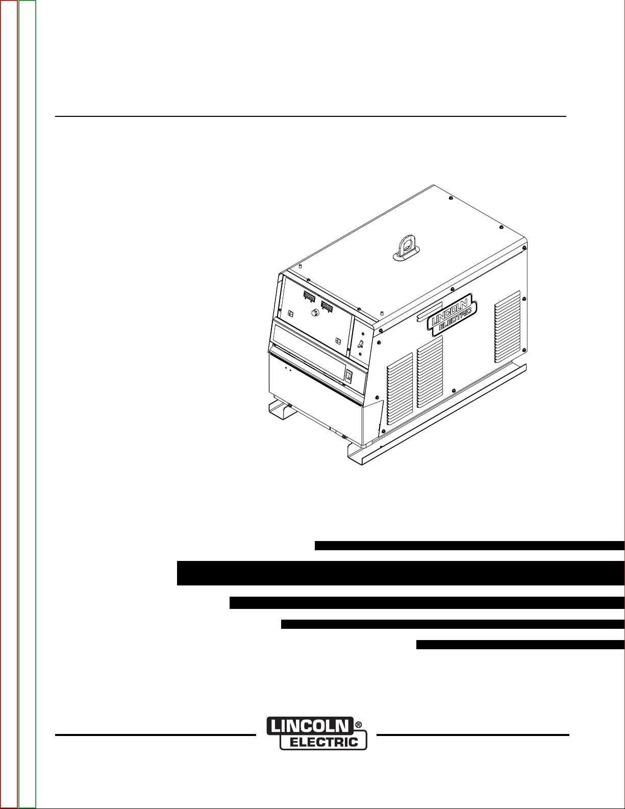
INVERTEC® V450-PRO
RETURN TO MAIN MENU
Safety Depends on You
Lincoln arc welding and cutting
equipment is designed and built
with safety in mind. However,
your overall safety can be
increased by proper installation
. . . and thoughtful operation on
your part. DO NOT INSTALL,
OPERATE OR REPAIR THIS
EQUIPMENT WITHOUT READING THIS MANUAL AND THE
SAFETY PRECAUTIONS CONTAINED THROUGHOUT. And,
most importantly, think before you
act and be careful.
RETURN TO MAIN INDEX
SVM199-A
July, 2010
For use with machine code number: 11212
View Safety Info View Safety Info View Safety Info View Safety Info
Return to Master TOC Return to Master TOC Return to Master TOC Return to Master TOC
Cleveland, Ohio 44117-1199 U.S.A. TEL: 888.935.3877 FAX: 216.486.1751 WEB SITE: www.lincolnelectric.com
SERVICE MANUAL
Copyright © Lincoln Global Inc.
• World's Leader in Welding and Cutting Products •
• Sales and Service through Subsidiaries and Distributors Worldwide •
Page 2
i i
SAFETY
WARNING
CALIFORNIA PROPOSITION 65 WARNINGS
Diesel engine exhaust and some of its constituents
are known to the State of California to cause cancer, birth defects, and other reproductive harm.
The Above For Diesel Engines
ARC WELDING can be hazardous. PROTECT YOURSELF AND OTHERS FROM POSSIBLE SERIOUS INJURY OR DEATH.
KEEP CHILDREN AWAY. PACEMAKER WEARERS SHOULD CONSULT WITH THEIR DOCTOR BEFORE OPERATING.
Read and understand the following safety highlights. For additional safety information, it is strongly recommended that you
purchase a copy of “Safety in Welding & Cutting - ANSI Standard Z49.1” from the American Welding Society, P.O. Box 351040,
Miami, Florida 33135 or CSA Standard W117.2-1974. A Free copy of “Arc Welding Safety” booklet E205 is available from the
Lincoln Electric Company, 22801 St. Clair Avenue, Cleveland, Ohio 44117-1199.
BE SURE THAT ALL INSTALLATION, OPERATION, MAINTENANCE AND REPAIR PROCEDURES ARE
PERFORMED ONLY BY QUALIFIED INDIVIDUALS.
The engine exhaust from this product contains
chemicals known to the State of California to cause
cancer, birth defects, or other reproductive harm.
The Above For Gasoline Engines
FOR ENGINE
powered equipment.
1.a. Turn the engine off before troubleshooting and maintenance
work unless the maintenance work requires it to be running.
____________________________________________________
1.b.Operate engines in open, well-ventilated
areas or vent the engine exhaust fumes
outdoors.
____________________________________________________
1.c. Do not add the fuel near an open flame welding arc or when the engine is running. Stop
the engine and allow it to cool before refueling to prevent spilled fuel from vaporizing on
contact with hot engine parts and igniting. Do
not spill fuel when filling tank. If fuel is spilled,
wipe it up and do not start engine until fumes
have been eliminated.
____________________________________________________
1.d. Keep all equipment safety guards, covers and devices in position and in good repair.Keep hands, hair, clothing and tools
away from V-belts, gears, fans and all other moving parts
when starting, operating or repairing equipment.
____________________________________________________
1.e. In some cases it may be necessary to remove safety
guards to perform required maintenance. Remove
guards only when necessary and replace them when the
maintenance requiring their removal is complete.
Always use the greatest care when working near moving
parts.
___________________________________________________
1.f. Do not put your hands near the engine fan.
Do not attempt to override the governor or
idler by pushing on the throttle control rods
while the engine is running.
1.h. To avoid scalding, do not remove the
radiator pressure cap when the engine is
hot.
ELECTRIC AND
MAGNETIC FIELDS
may be dangerous
2.a. Electric current flowing through any conductor causes
localized Electric and Magnetic Fields (EMF). Welding
current creates EMF fields around welding cables and
welding machines
2.b. EMF fields may interfere with some pacemakers, and
welders having a pacemaker should consult their physician
before welding.
2.c. Exposure to EMF fields in welding may have other health
effects which are now not known.
2.d. All welders should use the following procedures in order to
minimize exposure to EMF fields from the welding circuit:
2.d.1.
Route the electrode and work cables together - Secure
them with tape when possible.
2.d.2. Never coil the electrode lead around your body.
2.d.3. Do not place your body between the electrode and
work cables. If the electrode cable is on your right
side, the work cable should also be on your right side.
___________________________________________________
1.g. To prevent accidentally starting gasoline engines while
turning the engine or welding generator during maintenance
work, disconnect the spark plug wires, distributor cap or
magneto wire as appropriate.
Return to Master TOC Return to Master TOC Return to Master TOC Return to Master TOC
2.d.4. Connect the work cable to the workpiece as close as
possible to the area being welded.
2.d.5. Do not work next to welding power source.
INVERTEC® V450-PRO
Page 3
ii ii
SAFETY
ELECTRIC SHOCK can kill.
3.a. The electrode and work (or ground) circuits
are electrically “hot” when the welder is on.
Do not touch these “hot” parts with your bare
skin or wet clothing. Wear dry, hole-free
gloves to insulate hands.
3.b. Insulate yourself from work and ground using dry insulation.
Make certain the insulation is large enough to cover your full
area of physical contact with work and ground.
In addition to the normal safety precautions, if welding
must be performed under electrically hazardous
conditions (in damp locations or while wearing wet
clothing; on metal structures such as floors, gratings or
scaffolds; when in cramped positions such as sitting,
kneeling or lying, if there is a high risk of unavoidable or
accidental contact with the workpiece or ground) use
the following equipment:
• Semiautomatic DC Constant Voltage (Wire) Welder.
• DC Manual (Stick) Welder.
• AC Welder with Reduced Voltage Control.
3.c. In semiautomatic or automatic wire welding, the electrode,
electrode reel, welding head, nozzle or semiautomatic
welding gun are also electrically “hot”.
3.d. Always be sure the work cable makes a good electrical
connection with the metal being welded. The connection
should be as close as possible to the area being welded.
3.e. Ground the work or metal to be welded to a good electrical
(earth) ground.
3.f.
Maintain the electrode holder, work clamp, welding cable and
welding machine in good, safe operating condition. Replace
damaged insulation.
3.g. Never dip the electrode in water for cooling.
3.h. Never simultaneously touch electrically “hot” parts of
electrode holders connected to two welders because voltage
between the two can be the total of the open circuit voltage
of both welders.
3.i. When working above floor level, use a safety belt to protect
yourself from a fall should you get a shock.
3.j. Also see Items 6.c. and 8.
ARC RAYS can burn.
4.a. Use a shield with the proper filter and cover
plates to protect your eyes from sparks and
the rays of the arc when welding or observing
open arc welding. Headshield and filter lens
should conform to ANSI Z87. I standards.
4.b. Use suitable clothing made from durable flame-resistant
material to protect your skin and that of your helpers from
the arc rays.
4.c. Protect other nearby personnel with suitable, non-flammable
screening and/or warn them not to watch the arc nor expose
themselves to the arc rays or to hot spatter or metal.
FUMES AND GASES
can be dangerous.
5.a. Welding may produce fumes and gases
hazardous to health. Avoid breathing these
fumes and gases.When welding, keep
your head out of the fume. Use enough
ventilation and/or exhaust at the arc to keep
fumes and gases away from the breathing zone. When
welding with electrodes which require special
ventilation such as stainless or hard facing (see
instructions on container or MSDS) or on lead or
cadmium plated steel and other metals or coatings
which produce highly toxic fumes, keep exposure as
low as possible and within applicable OSHA PEL and
ACGIH TLV limits using local exhaust or mechanical ventilation. In confined spaces or in some circumstances,
outdoors, a respirator may be required. Additional precautions are also required when welding on galvanized
steel.
5. b. The operation of welding fume control equipment is affected
by various factors including proper use and positioning of the
equipment, maintenance of the equipment and the specific
welding procedure and application involved. Worker exposure level should be checked upon installation and periodically thereafter to be certain it is within applicable OSHA PEL
and ACGIH TLV limits.
5.c.
Do not weld in locations near chlorinated hydrocarbon
coming from degreasing, cleaning or spraying operations.
The heat and rays of the arc can react with solvent vapors
form phosgene, a highly toxic gas, and other irritating products.
vapors
to
Return to Master TOC Return to Master TOC Return to Master TOC Return to Master TOC
5.d. Shielding gases used for arc welding can displace air and
cause injury or death. Always use enough ventilation,
especially in confined areas, to insure breathing air is safe.
5.e. Read and understand the manufacturer’s instructions for this
equipment and the consumables to be used, including the
material safety data sheet (MSDS) and follow your
employer’s safety practices. MSDS forms are available from
your welding distributor or from the manufacturer.
5.f. Also see item 1.b.
INVERTEC® V450-PRO
Page 4

iii iii
SAFETY
WELDING and CUTTING
SPARKS can
cause fire or explosion.
6.a.
Remove fire hazards from the welding area.
If this is not possible, cover them to prevent
Remember that welding sparks and hot
materials from welding can easily go through small cracks
and openings to adjacent areas. Avoid welding near
hydraulic lines. Have a fire extinguisher readily available.
6.b. Where compressed gases are to be used at the job site,
special precautions should be used to prevent hazardous
situations. Refer to “Safety in Welding and Cutting” (ANSI
Standard Z49.1) and the operating information for the
equipment being used.
6.c. When not welding, make certain no part of the electrode
circuit is touching the work or ground. Accidental contact can
cause overheating and create a fire hazard.
6.d. Do not heat, cut or weld tanks, drums or containers until the
proper steps have been taken to insure that such procedures
will not cause flammable or toxic vapors from substances
inside. They can cause an explosion even
been “cleaned”. For information, purchase “Recommended
Safe Practices for the
Containers and Piping That Have Held Hazardous
Substances”, AWS F4.1 from the American Welding Society
(see address above).
6.e. Vent hollow castings or containers before heating, cutting or
welding. They may explode.
Sparks and spatter are thrown from the welding arc. Wear oil
6.f.
free protective garments such as leather gloves, heavy shirt,
cuffless trousers, high shoes and a cap over your hair. Wear
ear plugs when welding out of position or in confined places.
Always wear safety glasses with side shields when in a
welding area.
6.g. Connect the work cable to the work as close to the welding
area as practical. Work cables connected to the building
framework or other locations away from the welding area
increase the possibility of the welding current passing
through lifting chains, crane cables or other alternate circuits.
This can create fire hazards or overheat lifting chains or
cables until they fail.
6.h. Also see item 1.c.
the welding sparks from starting a fire.
though
they have
Preparation
for Welding and Cutting of
CYLINDER may explode
if damaged.
7.a. Use only compressed gas cylinders
containing the correct shielding gas for the
process used and properly operating
regulators designed for the gas and
pressure used. All hoses, fittings, etc. should be suitable for
the application and maintained in good condition.
7.b. Always keep cylinders in an upright position securely
chained to an undercarriage or fixed support.
7.c. Cylinders should be located:
• Away from areas where they may be struck or subjected to
physical damage.
• A safe distance from arc welding or cutting operations and
any other source of heat, sparks, or flame.
7.d. Never allow the electrode, electrode holder or any other
electrically “hot” parts to touch a cylinder.
7.e. Keep your head and face away from the cylinder valve outlet
when opening the cylinder valve.
7.f. Valve protection caps should always be in place and hand
tight except when the cylinder is in use or connected for
use.
7.g. Read and follow the instructions on compressed gas
cylinders, associated equipment, and CGA publication P-l,
“Precautions for Safe Handling of Compressed Gases in
Cylinders,” available from the Compressed Gas Association
1235 Jefferson Davis Highway, Arlington, VA 22202.
FOR ELECTRICALLY
powered equipment.
8.a. Turn off input power using the disconnect
switch at the fuse box before working on
the equipment.
8.b. Install equipment in accordance with the U.S. National
Electrical Code, all local codes and the manufacturer’s
recommendations.
8.c. Ground the equipment in accordance with the U.S. National
Electrical Code and the manufacturer’s recommendations.
6.I. Read and follow NFPA 51B “ Standard for Fire Prevention
During Welding, Cutting and Other Hot Work”, available from
NFPA, 1 Batterymarch Park,PO box 9101, Quincy, Ma
022690-9101.
6.j. Do not use a welding power source for pipe thawing.
Refer to http://www.lincolnelectric.com/safety for additional safety information.
Return to Master TOC Return to Master TOC Return to Master TOC Return to Master TOC
INVERTEC® V450-PRO
Page 5

iv iv
SAFETY
PRÉCAUTIONS DE SÛRETÉ
Pour votre propre protection lire et observer toutes les instructions
et les précautions de sûreté specifiques qui parraissent dans ce
manuel aussi bien que les précautions de sûreté générales suivantes:
Sûreté Pour Soudage A L’Arc
1. Protegez-vous contre la secousse électrique:
a. Les circuits à l’électrode et à la piéce sont sous tension
quand la machine à souder est en marche. Eviter toujours
tout contact entre les parties sous tension et la peau nue
ou les vétements mouillés. Porter des gants secs et sans
trous pour isoler les mains.
b. Faire trés attention de bien s’isoler de la masse quand on
soude dans des endroits humides, ou sur un plancher metallique ou des grilles metalliques, principalement dans
les positions assis ou couché pour lesquelles une grande
partie du corps peut être en contact avec la masse.
c. Maintenir le porte-électrode, la pince de masse, le câble de
soudage et la machine à souder en bon et sûr état defonctionnement.
d.Ne jamais plonger le porte-électrode dans l’eau pour le
refroidir.
e. Ne jamais toucher simultanément les parties sous tension
des porte-électrodes connectés à deux machines à souder
parce que la tension entre les deux pinces peut être le total
de la tension à vide des deux machines.
f. Si on utilise la machine à souder comme une source de
courant pour soudage semi-automatique, ces precautions
pour le porte-électrode s’applicuent aussi au pistolet de
soudage.
2. Dans le cas de travail au dessus du niveau du sol, se protéger
contre les chutes dans le cas ou on recoit un choc. Ne jamais
enrouler le câble-électrode autour de n’importe quelle partie du
corps.
3. Un coup d’arc peut être plus sévère qu’un coup de soliel, donc:
6. Eloigner les matériaux inflammables ou les recouvrir afin de
prévenir tout risque d’incendie dû aux étincelles.
7. Quand on ne soude pas, poser la pince à une endroit isolé de
la masse. Un court-circuit accidental peut provoquer un
échauffement et un risque d’incendie.
8. S’assurer que la masse est connectée le plus prés possible de
la zone de travail qu’il est pratique de le faire. Si on place la
masse sur la charpente de la construction ou d’autres endroits
éloignés de la zone de travail, on augmente le risque de voir
passer le courant de soudage par les chaines de levage,
câbles de grue, ou autres circuits. Cela peut provoquer des
risques d’incendie ou d’echauffement des chaines et des
câbles jusqu’à ce qu’ils se rompent.
9. Assurer une ventilation suffisante dans la zone de soudage.
Ceci est particuliérement important pour le soudage de tôles
galvanisées plombées, ou cadmiées ou tout autre métal qui
produit des fumeés toxiques.
10. Ne pas souder en présence de vapeurs de chlore provenant
d’opérations de dégraissage, nettoyage ou pistolage. La
chaleur ou les rayons de l’arc peuvent réagir avec les vapeurs
du solvant pour produire du phosgéne (gas fortement toxique)
ou autres produits irritants.
11. Pour obtenir de plus amples renseignements sur la sûreté, voir
le code “Code for safety in welding and cutting” CSA Standard
W 117.2-1974.
PRÉCAUTIONS DE SÛRETÉ POUR
LES MACHINES À SOUDER À
TRANSFORMATEUR ET À
REDRESSEUR
Return to Master TOC Return to Master TOC Return to Master TOC Return to Master TOC
a. Utiliser un bon masque avec un verre filtrant approprié ainsi
qu’un verre blanc afin de se protéger les yeux du rayonnement de l’arc et des projections quand on soude ou
quand on regarde l’arc.
b. Porter des vêtements convenables afin de protéger la peau
de soudeur et des aides contre le rayonnement de l‘arc.
c. Protéger l’autre personnel travaillant à proximité au
soudage à l’aide d’écrans appropriés et non-inflammables.
4. Des gouttes de laitier en fusion sont émises de l’arc de
soudage. Se protéger avec des vêtements de protection libres
de l’huile, tels que les gants en cuir, chemise épaisse, pantalons sans revers, et chaussures montantes.
5. Toujours porter des lunettes de sécurité dans la zone de
soudage. Utiliser des lunettes avec écrans lateraux dans les
zones où l’on pique le laitier.
INVERTEC® V450-PRO
1. Relier à la terre le chassis du poste conformement au code de
l’électricité et aux recommendations du fabricant. Le dispositif
de montage ou la piece à souder doit être branché à une
bonne mise à la terre.
2. Autant que possible, I’installation et l’entretien du poste seront
effectués par un électricien qualifié.
3. Avant de faires des travaux à l’interieur de poste, la debrancher à l’interrupteur à la boite de fusibles.
4. Garder tous les couvercles et dispositifs de sûreté à leur place.
Page 6

v v
SAFETY
Electromagnetic Compatibility (EMC)
Conformance
Products displaying the CE mark are in conformity with European Community Council Directive of 15 Dec
2004 on the approximation of the laws of the Member States relating to electromagnetic compatibility,
2004/108/EC. It was manufactured in conformity with a national standard that implements a harmonized
standard: EN 60974-10 Electromagnetic Compatibility (EMC) Product Standard for Arc Welding Equipment.
It is for use with other Lincoln Electric equipment. It is designed for industrial and professional use.
Introduction
All electrical equipment generates small amounts of electromagnetic emission. Electrical emission may be
transmitted through power lines or radiated through space, similar to a radio transmitter. When emissions
are received by other equipment, electrical interference may result. Electrical emissions may affect many
kinds of electrical equipment; other nearby welding equipment, radio and TV reception, numerical controlled
machines, telephone systems, computers, etc. Be aware that interference may result and extra precautions
may be required when a welding power source is used in a domestic establishment.
Installation and Use
The user is responsible for installing and using the welding equipment according to the manufacturer’s
instructions. If electromagnetic disturbances are detected then it shall be the responsibility of the user of the
welding equipment to resolve the situation with the technical assistance of the manufacturer. In some cases
this remedial action may be as simple as earthing (grounding) the welding circuit, see Note. In other cases
it could involve construction of an electromagnetic screen enclosing the power source and the work complete with associated input filters. In all cases electromagnetic disturbances must be reduced to the point
where they are no longer troublesome.
Note: The welding circuit may or may not be earthed for safety reasons according to national
codes. Changing the earthing arrangements should only be authorized by a person who is
competent to access whether the changes will increase the risk of injury, e.g., by allowing
parallel welding current return paths which may damage the earth circuits of other equipment.
Assessment of Area
Before installing welding equipment the user shall make an assessment of potential electromagnetic problems in the surrounding area. The following shall be taken into account:
a) other supply cables, control cables, signaling and telephone cables; above, below and adjacent to the
welding equipment;
b) radio and television transmitters and receivers;
c) computer and other control equipment;
d) safety critical equipment, e.g., guarding of industrial equipment;
e) the health of the people around, e.g., the use of pacemakers and hearing aids;
f) equipment used for calibration or measurement
g) the immunity of other equipment in the environment. The user shall ensure that other equipment being
used in the environment is compatible. This may require additional protection measures;
Return to Master TOC Return to Master TOC Return to Master TOC Return to Master TOC
h) the time of day that welding or other activities are to be carried out.
INVERTEC® V450-PRO
Page 7

vi vi
SAFETY
Electromagnetic Compatibility (EMC)
The size of the surrounding area to be considered will depend on the structure of the building and other
activities that are taking place. The surrounding area may extend beyond the boundaries of the premises.
Methods of Reducing Emissions
Mains Supply
Welding equipment should be connected to the mains supply according to the manufacturer’s recommendations. If interference occurs, it may be necessary to take additional precautions such as filtering of the
mains supply. Consideration should be given to shielding the supply cable of permanently installed welding
equipment, in metallic conduit or equivalent. Shielding should be electrically continuous throughout its
length. The shielding should be connected to the welding power source so that good electrical contact is
maintained between the conduit and the welding power source enclosure.
Maintenance of the Welding Equipment
The welding equipment should be routinely maintained according to the manufacturer’s recommendations.
All access and service doors and covers should be closed and properly fastened when the welding equipment is in operation. The welding equipment should not be modified in any way except for those changes
and adjustments covered in the manufacturers instructions. In particular, the spark gaps of arc striking and
stabilizing devices should be adjusted and maintained according to the manufacturer’s recommendations.
Welding Cables
The welding cables should be kept as short as possible and should be positioned close together, running at
or close to floor level.
Equipotential Bonding
Bonding of all metallic components in the welding installation and adjacent to it should be considered.
However, metallic components bonded to the work piece will increase the risk that the operator could
receive a shock by touching these metallic components and the electrode at the same time. The operator
should be insulated from all such bonded metallic components.
Earthing of the Workpiece
Where the workpiece is not bonded to earth for electrical safety, not connected to earth because of its size
and position, e.g., ships hull or building steelwork, a connection bonding the workpiece to earth may reduce
emissions in some, but not all instances. Care should be taken to prevent the earthing of the workpiece
increasing the risk of injury to users, or damage to other electrical equipment. Where necessary, the connection of the workpiece to earth should be made by a direct connection to the workpiece, but in some
countries where direct connection is not permitted, the bonding should be achieved by suitable capacitance, selected according to national regulations.
Screening and Shielding
Selective screening and shielding of other cables and equipment in the surrounding area may alleviate
problems of interference. Screening of the entire welding installation may be considered for special applica-
1
tions.
Return to Master TOC Return to Master TOC Return to Master TOC Return to Master TOC
_________________________
1
Portions of the preceding text are contained in EN 60974-10: “Electromagnetic Compatibility (EMC)
product standard for arc welding equipment.”
INVERTEC® V450-PRO
Page 8

I I
RETURN TO MAIN MENU
- MASTER TABLE OF CONTENTS FOR ALL SECTIONS -
Page
Safety . . . . . . . . . . . . . . . . . . . . . . . . . . . . . . . . . . . . . . . . . . . . . . . . . . . . . . . . . . . . . . . . . . . . . . . . . . .i-iv
Installation . . . . . . . . . . . . . . . . . . . . . . . . . . . . . . . . . . . . . . . . . . . . . . . . . . . . . . . . . . . . . . . . . .Section A
Operation . . . . . . . . . . . . . . . . . . . . . . . . . . . . . . . . . . . . . . . . . . . . . . . . . . . . . . . . . . . . . . . . . .Section B
Accessories . . . . . . . . . . . . . . . . . . . . . . . . . . . . . . . . . . . . . . . . . . . . . . . . . . . . . . . . . . . . . . . .Section C
Maintenance . . . . . . . . . . . . . . . . . . . . . . . . . . . . . . . . . . . . . . . . . . . . . . . . . . . . . . . . . . . . . . . .Section D
Theory of Operation . . . . . . . . . . . . . . . . . . . . . . . . . . . . . . . . . . . . . . . . . . . . . . . . . . . . . . . . . .Section E
Troubleshooting and Repair . . . . . . . . . . . . . . . . . . . . . . . . . . . . . . . . . . . . . . . . . . . . . . . . . . .Section F
Electrical Diagrams . . . . . . . . . . . . . . . . . . . . . . . . . . . . . . . . . . . . . . . . . . . . . . . . . . . . . . . . . .Section G
Parts Manual . . . . . . . . . . . . . . . . . . . . . . . . . . . . . . . . . . . . . . . . . . . . . . . . . . . . . . . . . . . . . . . . . . .P-525
INVERTEC® V450-PRO
Page 9

A-1 A-1
Installation . . . . . . . . . . . . . . . . . . . . . . . . . . . . . . . . . . . . . . . . . . . . . . . . . . . . . . . . . . . . . . . . . . . . . . . . . . . . .A-1
Technical Specifications . . . . . . . . . . . . . . . . . . . . . . . . . . . . . . . . . . . . . . . . . . . . . . . . . . . . . . . . . . . . . . . .A-2
Safety Precautions . . . . . . . . . . . . . . . . . . . . . . . . . . . . . . . . . . . . . . . . . . . . . . . . . . . . . . . . . . . . . . . . . . . .A-3
Location . . . . . . . . . . . . . . . . . . . . . . . . . . . . . . . . . . . . . . . . . . . . . . . . . . . . . . . . . . . . . . . . . . . . . . . . . . . .A-3
Lifting, Stacking & Machine Grounding . . . . . . . . . . . . . . . . . . . . . . . . . . . . . . . . . . . . . . . . . . . . . . . . . . . .A-3
High Frequency Protection . . . . . . . . . . . . . . . . . . . . . . . . . . . . . . . . . . . . . . . . . . . . . . . . . . . . . . . . . . . . . .A-3
Input Connection . . . . . . . . . . . . . . . . . . . . . . . . . . . . . . . . . . . . . . . . . . . . . . . . . . . . . . . . . . . . . . . . . . . . .A-3
Input Fuse and Supply Wire Considerations . . . . . . . . . . . . . . . . . . . . . . . . . . . . . . . . . . . . . . . . . . . . . . . .A-4
Negative Electrode Polarity . . . . . . . . . . . . . . . . . . . . . . . . . . . . . . . . . . . . . . . . . . . . . . . . . . . . . . . . . . . . .A-5
TABLE OF CONTENTS - INSTALLATION SECTION
Connections of Wire Feeders . . . . . . . . . . . . . . . . . . . . . . . . . . . . . . . . . . . . . . . . . . . . . . . . . . . . . . . . . . . .A-6
Parallel Operation . . . . . . . . . . . . . . . . . . . . . . . . . . . . . . . . . . . . . . . . . . . . . . . . . . . . . . . . . . . . . . . . . . . . .A-7
Return to Master TOC Return to Master TOC Return to Master TOC Return to Master TOC
INVERTEC® V450-PRO
Page 10

A-2 A-2
INSTALLATION
TECHNICAL SPECIFICATIONS -
INVERTEC® V450-PRO
INPUT AT RATED OUTPUT - THREE PHASE ONLY
INPUT VOLTS-
FREQUENCY
208/230/460/575V - 60HZ.
200/220/440/575V - 50HZ.
OUTPUT
CONDITIONS
AMPS / VOLTS / DUTY CYCLE
450A@38V.100%
570A@43V. 60%
400A@36V.100%
500A@40V. 60%
INPUT
CURRENT
AMPS
58/53/25/22
82/78/37/31
49/45/23/18
67/61/31/25
IDLE
POWER
400 Watts
Max.
POWER FACTOR
@ RATED OUTPUT
.95 MIN.
EFFICIENCY
@ RATED
OUTPUT
88%
OUTPUT
PULSE
FREQUENCY
0.15 - 1000 Hz
PULSE
VOLTAGE
RANGE
5 - 55 VDC
PULSE AND
BACKGROUND
TIME RANGE
100 MICRO SEC. -3.3
SEC.
(CIRCUIT BREAKER PROTECTED)
AUXILIARY POWER
24VAC
42VAC AT
10 AMPS
115VAC AT
15* AMPS
OPEN CIRCUIT VOLTAGE PROCESS CURRENT RANGE (DC) CURRENT
30-76
76
76
18-76
76
MIG/MAG
FCAW
SMAW
GTAW
Pulse
50-570 Average Amps
40-570 Average Amps
55-570 Average Amps
5-570 Average Amps
5-750 Peak Amps
RECOMMENDED INPUT WIRE AND FUSE SIZES FOR MAXIMUM RATED OUTPUT
INPUT
VOLTAGE /
FREQUENCY
208/50/60HZ
230/50/60HZ
460/50/60HZ
575/50/60HZ
TYPE 75°C
COPPER WIRE IN
CONDUIT AWG(MM2)
SIZES
4(25)
4(25)
8(10)
10(6)
TYPE 75°C
GROUND WIRE IN
CONDUIT AWG(MM2)
SIZES
8(10)
8(10)
10(6)
10(6)
TYPE 75°C
(SUPER LAG)
OR BREAKER
SIZE (AMPS)
100
100
50
40
PHYSICAL DIMENSIONS
HEIGHT
26.10 in
663 mm
WIDTH
19.86 in
505 mm
DEPTH
32.88 in
835 mm
WEIGHT
293 lbs.
133 kg.
TEMPERATURE RANGES
OPERATING TEMPERATURE RANGE
-20°C to +40°C
* Earlier models used 10 amps circuit breaker.
STORAGE TEMPERATURE RANGE
-40°C to +40°C
Return to Section TOC Return to Section TOC Return to Section TOC Return to Section TOC
Return to Master TOC Return to Master TOC Return to Master TOC Return to Master TOC
INVERTEC® V450-PRO
Page 11

A-3 A-3
INSTALLATION
SAFETY PRECAUTIONS
Read
start installation.
this entire installation section before you
WARNING
ELECTRIC SHOCK can kill.
• Only qualified personnel should
perform this installation.
• Turn the input power OFF at the
disconnect switch or fuse box
before working on this equipment. Turn off the input
power to any other equipment connected to the
welding system at the disconnect switch or fuse
box before working on the equipment.
• Do not touch electrically hot parts.
• Always connect the V450-PRO grounding lug
(located inside the reconnect input access door)
to a proper safety (Earth) ground.
--- -- --- - ---- -- --- - ---- -- --- - ---- -- --- - ---- -- --- - ---- -- ---
SELECT SUITABLE LOCATION
Do not use the Invertec® in outdoor environments without appropriate protection. The V450-PRO power
source should not be subjected to falling water, nor
should any parts of it be submerged in water. Doing so
may cause improper operation as well as pose a safety hazard. The best practice is to keep the machine in a
dry, sheltered area.
LIFTING
Lift the machine by the lift bail only. The lift bail is
designed to lift the power source only. Do not attempt
to lift the V450-PRO with accessories attached to it.
STACKING
V450-PRO machines can be stacked to a maximum of
3 high.
CAUTION
The bottom machine must always be placed on a
firm, secure, level surface. There is a danger of
machines toppling over if this precaution is not
taken.
MACHINE GROUNDING
The frame of the welder must be grounded. A ground
terminal marked with the symbol is located inside
the reconnect/input access door for this purpose. See
your local and national electrical codes for proper
grounding methods.
HIGH FREQUENCY PROTECTION
Locate the V450-PRO away from radio controlled
machinery.
WARNING
Do not mount the V450-PRO over combustible surfaces. Where there is a combustible surface directly under stationary or fixed electrical equipment,
that surface shall be covered with a steel plate at
least .060" (1.6mm) thick, which shall extend not
less than 5.90" (150mm) beyond the equipment on
all sides.
------------------------------------------------------------------------
Place the welder where clean cooling air can freely circulate in through the rear louvers and out through the
case sides and bottom. Water, Dirt, dust, or any foreign
material that can be drawn into the welder should be
kept at a minimum. Failure to observe these precautions can result in excessive operating temperatures
and nuisance shutdowns.
Machines are equipped with F.A.N. (fan as needed) circuitry. The fan runs whenever the output is enabled,
whether under loaded or open circuit conditions. The
fan also runs for a period of time (approximately 5 minutes) after the output is disabled, to ensure all components are properly cooled.
If desired, the F.A.N. feature can be disabled (causing
the fan to run whenever the power source is on). To disable F.A.N., connect leads 444 and X3A together at the
output of the solid state fan control relay, located on the
back of the Control PC board enclosure. (See Wiring
Diagram)
CAUTION
The normal operation of the V450-PRO may
adversely affect the operation of RF controlled
equipment, which may result in bodily injury or
damage to the equipment.
INPUT CONNECTION
WARNING
Only a qualified electrician should connect the
input leads to the V450-PRO. Connections should
be made in accordance with all local and national
electrical codes and the connection diagram located on the inside of the reconnect/input access
door of the machine. Failure to do so may result in
bodily injury or death.
------------------------------------------------------------------------
Use a three-phase supply line. A 1.75 inch (45 mm)
diameter access hole for the input supply is located on
the upper left case back next to the input access door.
Connect L1, L2, L3 and ground according to the Input
Supply Connection Diagram decal located on the
inside of the input access door or refer to Figure A.1 on
the following page.
Return to Section TOC Return to Section TOC Return to Section TOC Return to Section TOC
Return to Master TOC Return to Master TOC Return to Master TOC Return to Master TOC
INVERTEC® V450-PRO
Page 12
A-4 A-4
200-208V
220-230V
440-460V
550-575V
200-208V
220-230V
=
220-230V
220-230V
200-208V
220-230V
440-460V
550-575V
200-208V
U / L1
550-575V
440-460V
'A'
'A'
= 440-460V
'A'
S25198
VOLTAGEVOLTAGE
VOLTAGE
VOLTAGE
=
200-208V
THE LINCOLN ELECTRIC CO. CLEVELAND, OHIO U.S.A.
XA
'A'
= 550-575V
C
R1
W / L
3
V / L
2
440-460V
550-575V
.
inspecting or servicing machine.
Do not operate with covers
.
r
emoved.
Do not touch electrically live parts.
.
Only qualied persons should install,
use or service this equipment.
.
Disconnect input power before
INPUT SUPPLY CONNECTION DIAGRAM
WARNING
ELECTRIC
SHOCK
CAN KILL
200-208V
220-230V
440-460V
550-575V
200-208V
220-230V
=
220-230V
220-230V
200-208V
220-230V
440-460V
550-575V
200-208V
U / L1
550-575V
440-460V
'A'
'A'
= 440-460V
'A'
S25198
VOLTAGEVOLTAGE
VOLTAGE
VOLTAGE
=
200-208V
THE LINCOLN ELECTRIC CO. CLEVELAND, OHIO U.S.A.
XA
'A'
= 550-575V
C
R1
W / L
3
V / L
2
440-460V
550-575V
.
inspecting or servicing machine.
Do not operate with covers
.
r
emoved.
Do not touch electrically live parts.
.
Only qualied persons should install,
use or service this equipment.
.
Disconnect input power before
INPUT SUPPLY CONNECTION DIAGRAM
WARNING
ELECTRIC
SHOCK
CAN KILL
INSTALLATION
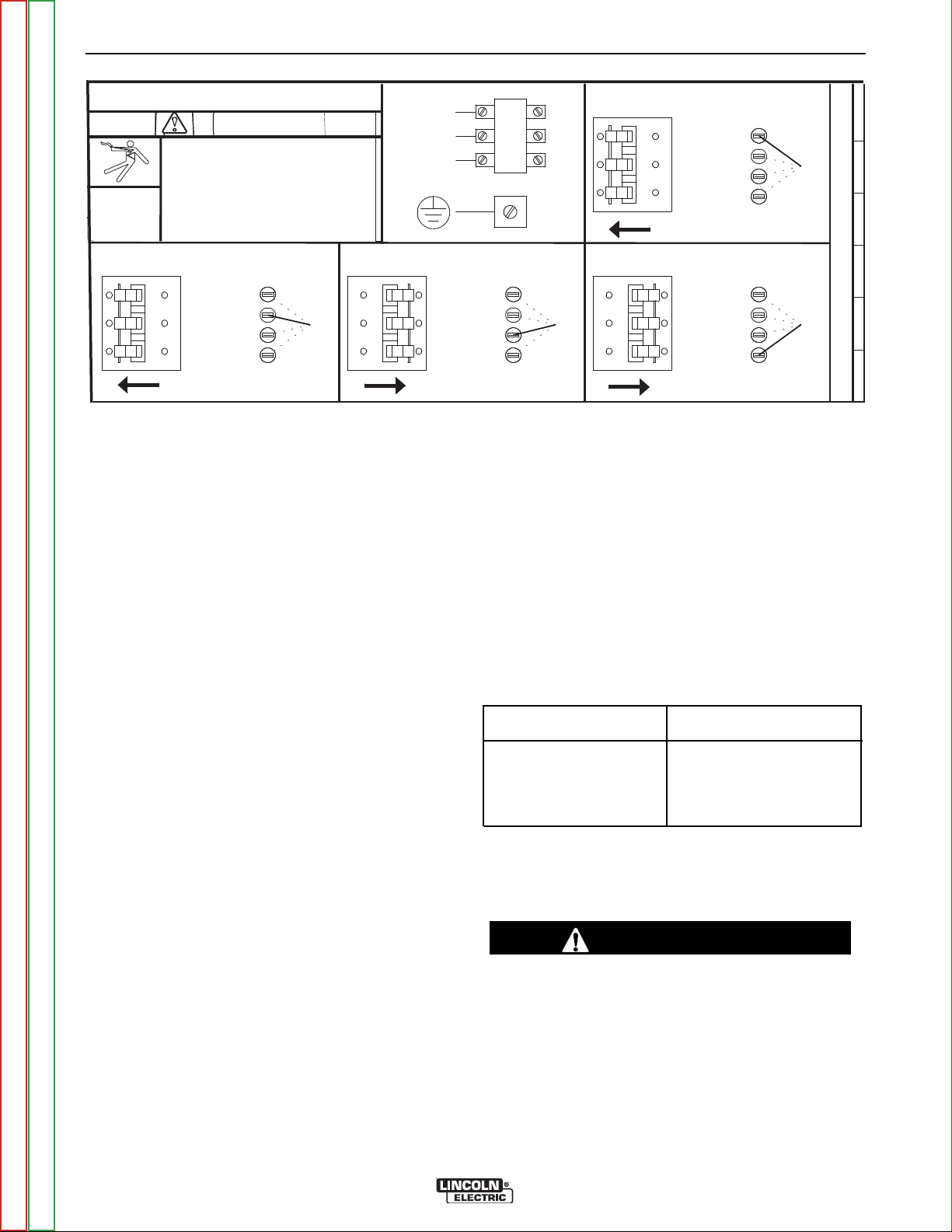
FIGURE A.1 - CONNECTION DIAGRAM ON CONNECTION/INPUT ACCESS DOOR
NOTE: Turn main input power to the machine OFF before performing connection procedure. Failure to do
so will result in damage to the machine.
INPUT FUSE AND SUPPLY WIRE
CONSIDERATIONS
Refer to the Technical Specifications at the beginning
of this Installation section for recommended fuse and
wire sizes. Fuse the input circuit with the recommended super lag fuse or delay type breakers (also called
“inverse time” or “thermal/magnetic” circuit breakers).
Choose an input and grounding wire size according to
local or national electrical codes. Using fuses or circuit
breakers smaller than recommended may result in
“nuisance” shut-offs from welder inrush currents, even
if the machine is not being used at high currents.
INPUT VOLTAGE CHANGE OVER (FOR
MULTIPLE INPUT VOLTAGE
MACHINES ONLY)
Welders are shipped connected for the highest input
voltage listed on the rating plate. To move this connection to a different input voltage, see the diagram located on the inside of the input access door. If the main
reconnect switch or link position is placed in the wrong
position, the welder will not produce output power.
Return to Section TOC Return to Section TOC Return to Section TOC Return to Section TOC
If the Auxiliary (A) lead is placed in the wrong position,
there are two possible results. If the lead is placed in a
position higher than the applied line voltage, the welder
may not come on at all. If the Auxiliary (A) lead is
placed in a position lower than the applied line voltage,
the welder will not come on, and the two circuit breakers or fuses in the reconnect area will open. If this
occurs, turn off the input voltage, properly connect the
(A) lead, reset the breakers, and try again. For
machines equipped with a fuse in the reconnect area,
turn off the input voltage and replace the fuse with the
spare fuse that is attached to the reconnect switch pin.
Return to Master TOC Return to Master TOC Return to Master TOC Return to Master TOC
INVERTEC® V450-PRO
ELECTRODE AND WORK CABLE
CONNECTIONS
Connect a work lead of sufficient size and length (Per
Table 1) between the proper output terminal on the
power source and the work. Be sure the connection to
the work makes tight metal-to-metal electrical contact.
To avoid interference problems with other equipment
and to achieve the best possible operation, route all
cables directly to the work and wire feeder. Avoid
excessive lengths and do not coil excess cable.
Minimum work and electrode cable sizes are as follows:
TABLE A.1
(Current (60% Duty Cycle)
400 Amps 2/0 (67 mm2)
500 Amps 3/0 (85 mm2)
600 Amps 3/0 (85 mm2)
NOTE: K1796 coaxial welding cable is recommended
to reduce the cable inductance in long cable lengths.
This is especially important when Pulse welding up to
350 amps.
When using inverter type power sources like the
V450-PRO, use the largest welding (electrode and
work) cables that are practical. At least 2/0 (67
2
) copper wire - even if the average output cur-
mm
CAUTION
rent would not normally require it. When pulsing,
the pulse current can reach very high levels.
Voltage drops can become excessive, leading to
poor welding characteristics, if undersized welding
cables are used.
------------------------------------------------------------------------
MINIMUM COPPER
WORK CABLE SIZE AWG
Up To-100 Ft. Length (30 m)
Page 13
A-5 A-5
B
A
C
FIGURE A.2
WORK
V450-PRO
A
C
B
FIGURE A.3
K1796 COAXIAL CABLE
MEASURE FROM END
OF OUTER JACKET OF
CABLE
C
A
B
WORK
SLIDING
WORK
V
450-PRO
A
C
B
FIGURE A.3
K1796 COAXIAL CABLE
MEASURE FROM END
OF OUTER JACKET OF
CABLE
C
A
B
WORK
SLIDING
WORK
V
450-PRO
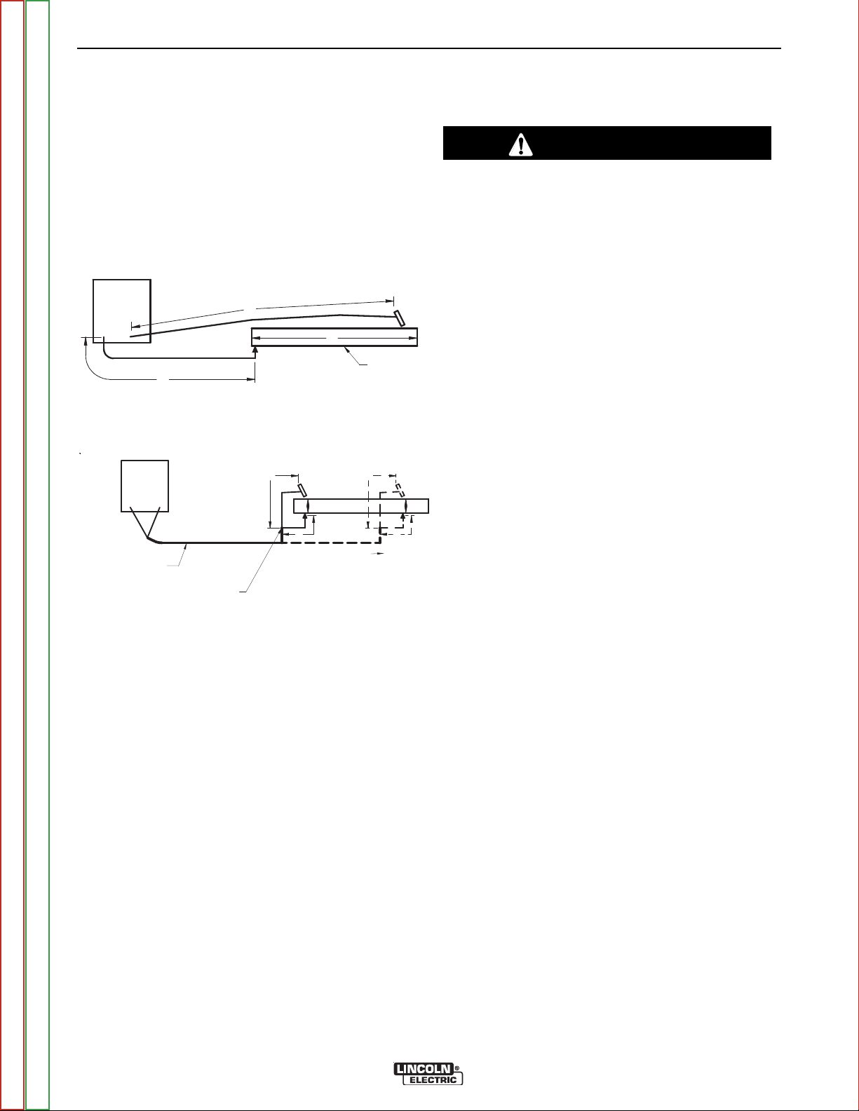
CABLE INDUCTANCE, AND ITS EFFECTS
ON PULSE WELDING
For Pulse Welding processes, cable inductance will
cause the welding performance to degrade. For the
total welding loop length less than
tional welding cables may be used without any effects
on welding performance. For the total welding loop
length greater than
50 ft. (15.24m), the K1796 Coaxial
Welding Cables are recommended. The welding loop
length is defined as the total of electrode cable length
(A) + work cable length (B) + work length (C) (See
Figure A.2).
50 ft.(15.24m), tradi-
INSTALLATION
For additional Safety information regarding the electrode and work cable set-up, See the standard "SAFETY INFORMATION" located in the front of the
Instruction Manuals.
CAUTION
Excessive voltage drops caused by poor work
piece connections often result in unsatisfactory
welding performance.
------------------------------------------------------------------------
NEGATIVE ELECTRODE POLARITY
When negative electrode polarity is required, such as in
some Innershield applications, switch the output connections at the power source (electrode cable to the
negative (-) stud, and work cable to the positive (+)
stud.
For long work piece lengths, a sliding ground should be
considered to keep the total welding loop length less
50 ft.(15.24m). (See Figure A.3.)
than
Return to Master TOC Return to Master TOC Return to Master TOC Return to Master TOC
Return to Section TOC Return to Section TOC Return to Section TOC Return to Section TOC
Output connections on some V450-PRO are made via
1/2-13 threaded output studs located beneath the
spring-loaded output cover at the bottom of the case
front.
Most welding applications run with the electrode being
positive (+). For those applications, connect the electrode cable between the wire feeder and the positive
(+) output stud on the power source (located beneath
the spring loaded output cover near the bottom of the
case front). Connect the other end of the electrode
cable to the wire drive feed plate. The electrode cable
lug must be against the feed plate. Be sure the connection to the feed plate makes tight metal-to-metal
electrical contact. The electrode cable should be sized
according to the specifications given in the work cable
connections section. Connect a work lead from the
negative (-) power source output stud to the work
piece. The work piece connection must be firm and
secure, especially if pulse welding is planned.
INVERTEC® V450-PRO
Page 14
A-6 A-6
14-PIN
STUD
WORK CLAMP
ELECTRODE CABLE
V450-PRO
ACROSS THE ARC MODEL
CONROL CABLE MODEL
OUTPUT TERMINALS
ALWAYS HOT.
POWER SOURCE CONTACTOR
SWITCH MUST BE IN THE
“ON” POSITION OR USE A
K848 JUMPER PLUG KIT.
MAGNUM GUN
AND CABLE
ASSEMBLY
LN-15
SEMIAUTOMATIC
WIRE FEEDER
K1870-1
14-PIN
STUD
ELECTRODE CABLE
V450-PRO
K1819-10
CONTROL CABLE
MAGNUM GUN
AND CABLE
ASSEMBLY
LN-15
SEMIAUTOMATIC
WIRE FEEDER
K1871-1 MODEL
14-PIN
STUD
WORK CLAMP
ELECTRODE CABLE
V450-PRO
ACROSS THE ARC MODEL
CONROL CABLE MODEL
OUTPUT TERMINALS
ALWAYS HOT.
POWER SOURCE CONTACTOR
SWITCH MUST BE IN THE
“ON” POSITION OR USE A
K848 JUMPER PLUG KIT.
MAGNUM GUN
AND CABLE
ASSEMBLY
LN-15
SEMIAUTOMATIC
WIRE FEEDER
K1870-1
14-PIN
STUD
ELECTRODE CABLE
V450-PRO
K1819-10
CONTROL CABLE
MAGNUM GUN
AND CABLE
ASSEMBLY
LN-15
SEMIAUTOMATIC
WIRE FEEDER
K1871-1 MODEL
INSTALLATION
CONNECTIONS OF WIRE FEEDERS TO V450-PRO
LF-72, 74 Connection Instructions
• Turn the Invertec® power switch "off".
• Connect the K1797-[ ] control cable from the LF-72, 74
to the 14-pin MS-style connector.
• Connect the electrode cable to the output terminal of the
polarity required by electrode. Connect the work lead to
the other terminal.
• If a remote control such as K857 is to be used with the
LF-72, 74 the remote can be connected directly to the 6pin MS-style connector on the front of the Invertec® or
use a K864 adapter to connect the LF-72, 74 and the
remote to the 14-pin MS-style connector.
LN-10, DH-10 Connection Instructions
• Turn the Invertec® power switch "off"
• Connect the K1505 control cable from the LN-10 to the
14-pin MS-style connector.
• Connect the electrode cable to the output terminal of
polarity required by the electrode. Connect the work lead
to the other terminal.
• Set the meter polarity switch on the front of the Invertec®
to coincide with wire feeder polarity used.
• See the LN-10 manual for details on accessing Control
DIP Switch. Dip Switches for the V350 and the same settings may be used for the V450.
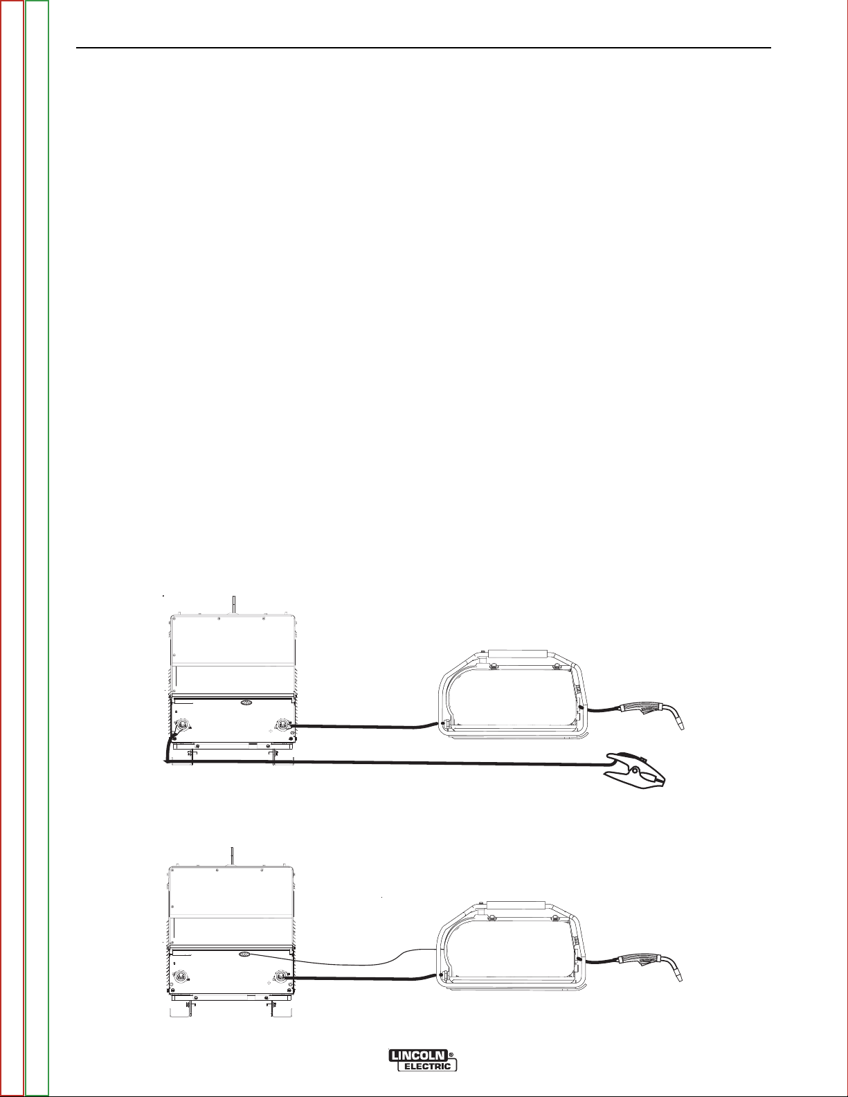
LN-15 Connection Instructions
(See Figure A.4)
• Turn the Invertec® power switch "off".
• Connect the electrode cable to the output terminal of polarity required by electrode. (See Figures below)
• Set the meter polarity switch on the front of the Invertec®
to coincide with wire feeder polarity used.
LN-25 Connection Instructions
• Turn the Invertec® power switch "off".
• Connect the electrode cable to the output terminal of polarity required by electrode. Connect the work lead to the
other terminal.
• LN-25 with Remote Control 6-Pin (K444-1) and 14-pin
(K444-2) remotes can be connected directly to the 6-pin &
14-pin MS-style connectors. The 42 Volt Remote Voltage
and Output Control (K624-1) Kit can be connected to the
V450’s 14-pin MS-style connector using Remote Control
Cable assembly K627- [ ]. LN-25s with a K431-1 remote kit
can be connected to the V450’s 14-pin MS-style connector
using a K432 cable and K876 adapter. (See connection
diagram S19899). Or the K432 cable could be modified
with a K867 Universal Adapter Plug (See connection diagram S19405) to connect it to the V450’s 14-pin MS-style
connector.
FIGURE A.4
Return to Master TOC Return to Master TOC Return to Master TOC Return to Master TOC
Return to Section TOC Return to Section TOC Return to Section TOC Return to Section TOC
INVERTEC® V450-PRO
Page 15

A-7 A-7
INSTALLATION
LN-742 Connection Instructions
• Turn the Invertec® power switch "off"
• A K1819-1 Input cable assembly is required to connect the LN-742 to the Invertec®.
• Connect the control cable from the LN-742 to the
14-pin MS-style connector.
• Connect the electrode cable to the output terminal
of the polarity required by electrode. Connect the
work lead to the other terminal.
• Set the meter polarity switch on the front of the
Invertec® to coincide with wire feeder polarity used.
The wire feeder will now display the welding voltage.
• If a remote control such as K857 is to be used with the
LN-742, the remote can be connected directly to the 6-pin
MS-style connector on the front of the Invertec® or use a
K864 adapter to connect the LN-742 and the remote to
the 14-pin MS-style connector.
Cobramatic Connection Instructions
• Turn the Invertec® power switch "off"
• Connect the control cable from the Cobramatic to
the 14-pin MS-style connector.
• Connect the electrode cable to the output terminal
of the polarity required by electrode. Connect the
work lead to the other terminal.
• Set the meter polarity switch on the front of the
Invertec® to coincide with wire feeder polarity used.
• If a remote control such as K857 is to be used with
the Cobramatic, the remote can be connected
directly to the 6-pin MS-style connector on the front
of the Invertec® or use a K864 adapter to connect
the cobramatic and the remote to the 14-pin MSstyle connector.
General Instructions for Connection of Wire
Feeders to V450-Pro
Wire feeders other than those listed above may be
used provided that the auxiliary power supply rating of
the V450-Pro is not exceeded and the V450-PRO output is not actively controlled by the wire feeder. (Like
an LN-9). K867 universal adapter plug is required. See
connection diagram S24985 in Operator Manual.
REMOTE CONTROL OF INVERTEC®
Remote Control K857, Hand Amptrol K963 and Foot
Amptrol K870 may be used.
PARALLEL OPERATION
The V450-Pro are operable in parallel in CC mode. For
best results, the currents of each machine should be
reasonably equally balanced. As an example, with two
machines set up in parallel for a 800 amps procedure,
each machine should be set to deliver approximately
400 amps, not 450 amps from one and 350 amps from
the other. This will minimize nuisance shutdown conditions. In general, more than two machines in parallel
will not be effective due to the voltage requirements of
procedures in that power range.
To set machine outputs, start with output control pots
and arc control pots in identical positions. Use the output control pots to balance the currents and maintain
the desired current. The arc control pots should be
kept identical on the two machines.
Return to Section TOC Return to Section TOC Return to Section TOC Return to Section TOC
TIG Module K930-2
The TIG Module connects to the Factory and Advanced
Process
control cable. Connect the K936-1 to the 14-Pin MSstyle connector.
Return to Master TOC Return to Master TOC Return to Master TOC Return to Master TOC
V450-Pro versions with a K936-1 (9-14 pin)
INVERTEC® V450-PRO
Page 16

A-8 A-8
NOTES
Return to Section TOC Return to Section TOC Return to Section TOC Return to Section TOC
Return to Master TOC Return to Master TOC Return to Master TOC Return to Master TOC
INVERTEC® V450-PRO
Page 17

B-1 B-1
Operation . . . . . . . . . . . . . . . . . . . . . . . . . . . . . . . . . . . . . . . . . . . . . . . . . . . . . . . . . . . . . . . . . . . . . . . . . . . . . .B-1
Safety Precautions . . . . . . . . . . . . . . . . . . . . . . . . . . . . . . . . . . . . . . . . . . . . . . . . . . . . . . . . . . . . . . . . . . . .B-2
General Description . . . . . . . . . . . . . . . . . . . . . . . . . . . . . . . . . . . . . . . . . . . . . . . . . . . . . . . . . . . . . . . . . . .B-2
Case Front Controls . . . . . . . . . . . . . . . . . . . . . . . . . . . . . . . . . . . . . . . . . . . . . . . . . . . . . . . . . . . . . . . . . . .B-2
Hidden Middle Control Panel . . . . . . . . . . . . . . . . . . . . . . . . . . . . . . . . . . . . . . . . . . . . . . . . . . . . . . . . . . . .B-3
TIG GTAW . . . . . . . . . . . . . . . . . . . . . . . . . . . . . . . . . . . . . . . . . . . . . . . . . . . . . . . . . . . . . . . . . . . . . . . . . .B-4
CV-Innershield . . . . . . . . . . . . . . . . . . . . . . . . . . . . . . . . . . . . . . . . . . . . . . . . . . . . . . . . . . . . . . . . . . . . . . .B-4
Weld Mode Select . . . . . . . . . . . . . . . . . . . . . . . . . . . . . . . . . . . . . . . . . . . . . . . . . . . . . . . . . . . . . . . . . . . .B-5
Memory Selections . . . . . . . . . . . . . . . . . . . . . . . . . . . . . . . . . . . . . . . . . . . . . . . . . . . . . . . . . . . . . . . . . . . .B-6
TABLE OF CONTENTS - OPERATION SECTION
Weld Mode Details . . . . . . . . . . . . . . . . . . . . . . . . . . . . . . . . . . . . . . . . . . . . . . . . . . . . . . . . . . . . . . . . . . . .B-7
Pulse Programs . . . . . . . . . . . . . . . . . . . . . . . . . . . . . . . . . . . . . . . . . . . . . . . . . . . . . . . . . . . . . . . . . . . . . .B-8
Remote Control Selection . . . . . . . . . . . . . . . . . . . . . . . . . . . . . . . . . . . . . . . . . . . . . . . . . . . . . . . . . . . . . .B-9
Limitations . . . . . . . . . . . . . . . . . . . . . . . . . . . . . . . . . . . . . . . . . . . . . . . . . . . . . . . . . . . . . . . . . . . . . . . . .B-10
Return to Master TOC Return to Master TOC Return to Master TOC Return to Master TOC
INVERTEC® V450-PRO
Page 18
B-2 B-2
SAFETY PRECAUTIONS
WARNING
ELECTRIC SHOCK can kill.
• Do not touch electrically live parts or
electrode with skin or wet clothing.
• Insulate yourself from work and
ground.
• Always wear dry insulating gloves.
------------------------------------------------------------------------
FUMES AND GASES can be dangerous.
• Keep your head out of fumes.
• Use ventilation or exhaust to remove
fumes from breathing zone.
-------------------------------------------------------
-----------------
WELDING SPARKS can cause fire or
explosion.
• Keep flammable material away.
• Do not weld on closed containers.
OPERATION
• After welding, the meter holds the actual current
value for 5 seconds. Output adjustment while in the
"hold" period results in the "prior to operation" characteristics stated above. The displays blink indicating that the machine is in the "Hold" period.
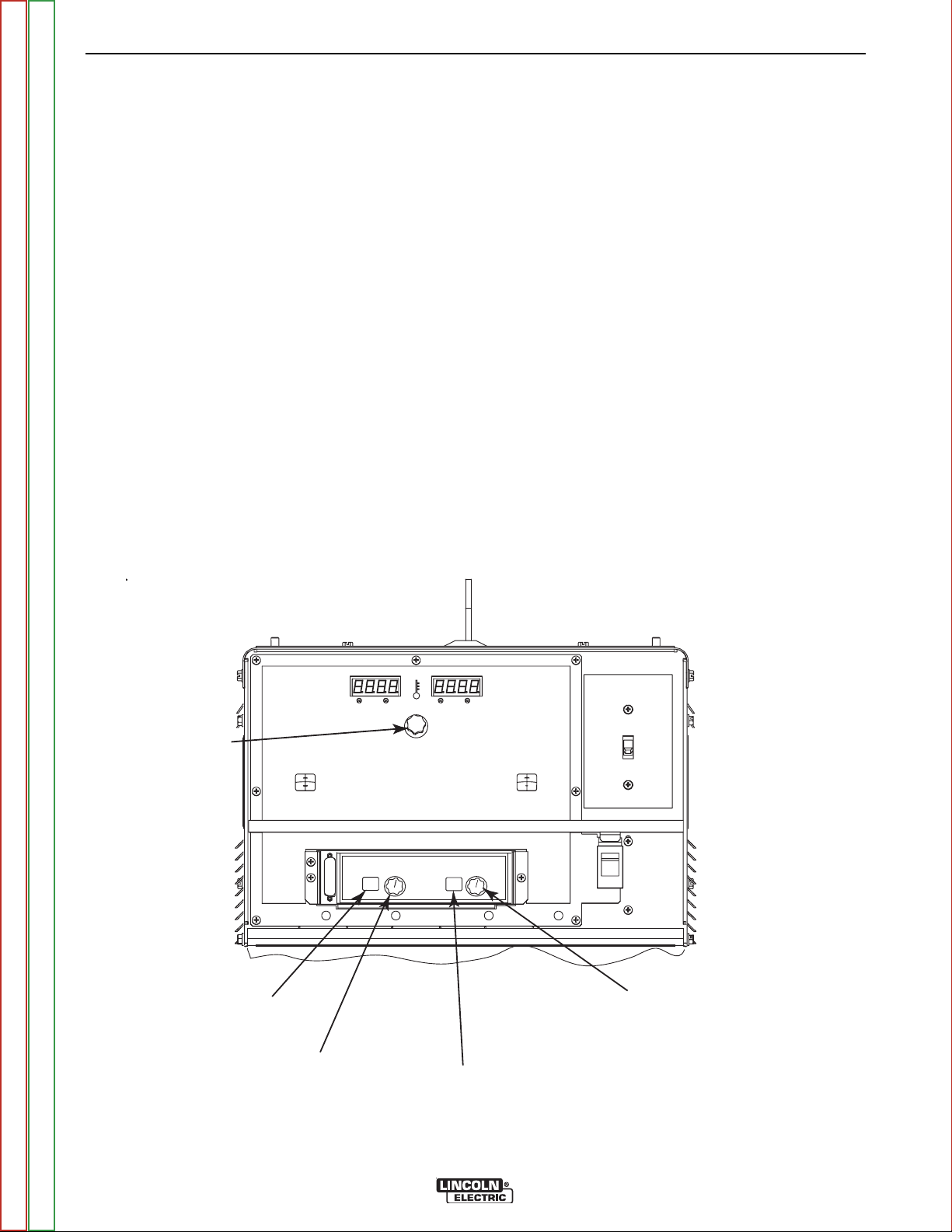
3. VOLT METER
• Prior to CV operation (current flow), the meter displays desired preset voltage value (+/- .5V).
• Prior to STICK or TIG operation, the meter displays
the Open Circuit Voltage of the Power Source or four
dashes if the output has not been turned on.
• During welding, this meter displays actual average
volts.
• After welding, the meter holds the actual voltage
value for 5 seconds. The displays blink indicating
that the machine is in the "Hold" period.
• Output adjustment while in the "hold" period results
in the "prior to operation" characteristics stated
above.
------------------------------------------------------------------------
ARC RAYS can burn eyes and skin.
• Wear eye, ear and body
protection.
------------------------------------------------------------
See additional warning information at
front of this operator’s manual.
-----------------------------------------------------------
GENERAL DESCRIPTION
The Invertec® V450-Pro offers multi-process CV, CC,
and DC welding and is rated 570 amps, 43 volts at a
60% duty cycle.
DUTY CYCLE
The V450-Pro is rated at 570 amps, 60% duty cycle
(based on a 10 minute cycle). It is also rated at 450
amps, 100% duty cycle.
OPERATIONAL FEATURES and CONTROLS:
UPPER CONTROL PANEL
1. ON, OFF- SWITCH
4. OUTPUT CONTROL
• Output control is conducted via a single turn potentiometer.
• Adjustment is indicated by the meters as stated
above.
• When in TIG modes, this control sets the maximum
welding current. Full depression of a foot or hand
Amptrol results in the preset level of current.
5. WELD TERMINALS-REMOTE / ON
• Two status lights indicate the location of trigger control as determined by the "WELD TERMINALS" push
button.
• If trigger control is local "weld terminals on", the ON
display will be lit.
• If trigger control is remote "weld terminals remotely
controlled", the REMOTE display will be lit.
• The unit will power up in "pre-determined preferred"
trigger modes.
STICK = ON
CV = REMOTE
TIG = REMOTE if remote output controls are attached
to the machine.
Return to Section TOC Return to Section TOC Return to Section TOC Return to Section TOC
2. AMPS Meter
• Prior to STICK or TIG operation (current flow), the
meter displays preset current value (either +/- 2
amps or +/- 3% (e.g. 3 amps on 100), whichever is
greater).
• Prior to CV operation, the meter displays four dashes indicating AMPS unable to be preset.
• During welding, this meter displays actual average
amps.
Return to Master TOC Return to Master TOC Return to Master TOC Return to Master TOC
TIG = ON if remote output controls are not attached to
the machine.
For all versions, these trigger modes can be over-ridden
(switched) with the WELD TERMINALS push button. When
changed, the unit will power up in the configuration it was in
INVERTEC® V450-PRO
Page 19

B-3 B-3
OUTPUTOUTPUT
MPSMPS
AA
O
LTSOLTS
VV
REMOTEREMOTE
LOCALLOCAL
CONTROLCONTROL
SELECTSELECT
SOFT
C
RIP
HI-FREQ
TIG
TOUCH
S
TART
TIG
OUTPUTOUTPUT
MPSMPS
AA
O
LTSOLTS
VV
REMOTEREMOTE
LOCALLOCAL
CONTROLCONTROL
SELECTSELECT
SOFT
C
RIP
HI-FREQ
TIG
TOUCH
S
TART
TIG
6.
THERMAL
• This status light indicates when the power source has been
driven into thermal overload. If the output terminals were
OPERATION
CC-STICK SOFT: The Stick Soft process features contin-
uous control ranging from 5 to 570 amps. This mode was
intended for most SMAW applications, and Arc Gouging.
"ON", the "ON" light will blink indicating that the output will
be turned back on once the unit cools down to an acceptable temperature level. If the unit was operating in the
"REMOTE" mode, the trigger will need to be opened
before or after the thermal has cleared and closed after the
machine has cooled down to an acceptable temperature to
establish output.
• Arc Gouging: Setting the output of the Stick Soft
mode to 570 amps or setting the arc control to maximum will enable the arc-gouging mode. The actual output current will depend on the size of carbon used. The
recommended maximum size carbon is 3/8"(9.5mm).
• The Hot Start control regulates the starting current at
arc initiation. Hot Start can be adjusted from minimum
7.
CONTROL-REMOTE / LOCAL
• Two status lights indicate the location of output control as
pre-determined by the power sources auto-configure system.
• The LOCAL display will be lit when control is at the power
source.
• The REMOTE display will be lit when a remote pot/control
is detected.
These Output Control configurations can be overridden
(switched) with the CONTROL push button. When changed,
the unit will power up in the configuration it was in when it
was last powered down.
(0), with no additional current added at arc start, to
maximum (10), with double the preset current or 570
amps (max of machine) added for the first second after
arc initiation.
• The Arc Control regulates the Arc Force to adjust the
short circuit current. The minimum setting (-10) will produce a "soft" arc and will produce minimal spatter. The
maximum setting (+10) will produce a "crisp" arc and
will minimize electrode sticking.
CC-STICK CRISP:The Stick Crisp mode features continuous control from 5 to 570 amps with a crisp shorting
response optimized for E6010 type electrodes.
Hidden Middle Control Panel – Process Set Up
Panel
The middle control panel is removable to allow for
upgrades (see Field Installed Options/Accessories).
Additionally, this panel is hidden by an access door to
provide protection to the controls.
8. WELD MODE SELECT - STANDARD (See
Figure B.1)
The Mode Control button selects from the following
welding modes.
2
6
7
8
9
• Arc Gouging: Setting the output of the Crisp mode to
570 amps or setting the arc control to maximum will
enable the arc-gouging mode. The actual output current will depend on the size of carbon used. The recommended maximum size carbon is 3/8"(9.5mm).
• The Hot Start control regulates the starting current at
arc initiation. Hot Start can adjust starting current up or
down by 25% of the preset value. The recommended
setting for Hot Start is 5 where the initial current is
equal to the preset current.
FIGURE B.1
3
4
1
5
10
13
14
12
11
15
Return to Master TOC Return to Master TOC Return to Master TOC Return to Master TOC
Return to Section TOC Return to Section TOC Return to Section TOC Return to Section TOC
INVERTEC® V450-PRO
Page 20

B-4 B-4
• The Arc Control regulates the Arc Force to adjust the
short circuit current. The minimum setting (-10) will
produce a "soft" arc and will produce minimal spatter. The maximum setting (+10) will produce a "crisp"
arc and will minimize electrode sticking.
TIG GTAW: The TIG mode features continuous control
from 5 to 570 amps. The TIG mode can be run in either
the TIG touch start or high frequency (optional equipment required) assisted start mode.
• The Hot Start control selects the starting mode
desired. A setting of less than 5, the TIG lift start
mode is selected. The OCV is controlled below 10v
and the short circuit "TIG touch" current is maintained at 25 amps independent of the preset current.
When the tungsten is lifted, an arc is initiated and
the output is regulated at the preset value. Hot start
settings between 0 and 5 regulate the arc initiation
current. A setting of 5 results in the most positive arc
initiation. A setting of 0 reduces hot start.
• Hot Start settings between 5 and 10, select high frequency assisted starting TIG mode. In this range,
the OCV of the machine is controlled between 50
and 70 volts. If using the Lincoln K930-1 TIG
Module, set the Hot start to 10 for maximum OCV.
• The Arc Control is not used in the TIG mode.
OPERATION
CV-WIRE: The CV-WIRE mode features continuous
control from 10 to 40 volts. This mode was intended for
most GMAW, FCAW, and MCAW applications.
• The Hot Start control is not used in the CV-WIRE
mode.
• The Arc Control regulates pinch effect. At the minimum setting (-10), minimizes pinch and results in a
soft arc. Low pinch settings are preferable for welding with gas mixes containing mostly inert gases. At
the maximum setting (+10), maximizes pinch effect
and results in a crisp arc. High pinch settings are
preferable for welding FCAW and GMAW with CO
CV-INNERSHIELD: The CV-INNERSHIELD mode
features continuous control from 10 to 45 volts. This
mode was designed for self-shielded flux cored wires
that require tight voltage control.
• The Hot Start control is not used in the CV-INNERSHIELD mode.
• The Arc Control regulates pinch effect. At the minimum setting (-10), minimizes pinch and results in a
soft arc. At the maximum setting (+10), maximizes
pinch effect and results in a crisp arc. Most selfed wires work well at an Arc Control setting of 5.
2.
shield-
Return to Section TOC Return to Section TOC Return to Section TOC Return to Section TOC
Return to Master TOC Return to Master TOC Return to Master TOC Return to Master TOC
INVERTEC® V450-PRO
Page 21
B-5 B-5
OUTPUT KNOBOUTPUT KNOB
REMOTEREMOTE
ONON
REMOTEREMOTE
LOCALLOCAL
WELD TERMINALSWELD TERMINALS
CONTROLCONTROL
SELECTSELECT
SELECTSELECT
MPSMPS
AA
OLTSOLTS
VV
ADVANCE PROCESS PANEL- MIDDLE SECTION OF WELDER (OPTIONAL)
MEMORYMEMORY
MEMORY BUTTON MEMORY BUTTON
(M1 THRU M8)(M1 THRU M8)
SELECT BUTTONSELECT BUTTON
(HOT START OR ARC CONTROL)(HOT START OR ARC CONTROL)
ADJUST KNOB ADJUST KNOB
(0 THRU +10 HOT START) (0 THRU +10 HOT START)
(-10 THRU 0 AND 0 THRU +10 ARC CONTROL)(-10 THRU 0 AND 0 THRU +10 ARC CONTROL)
SELECT KNOB SELECT KNOB
(SCOLLS WELDING PROCESSES)(SCOLLS WELDING PROCESSES)
SELECTSELECT
ADJUST ADJUST
SELECTSELECT
OUTPUT KNOBOUTPUT KNOB
REMOTEREMOTE
ONON
REMOTEREMOTE
LOCALLOCAL
WELD TERMINALSWELD TERMINALS
CONTROLCONTROL
SELECTSELECT
SELECTSELECT
MPSMPS
AA
OLTSOLTS
VV
ADVANCE PROCESS PANEL- MIDDLE SECTION OF WELDER (OPTIONAL)
MEMORYMEMORY
MEMORY BUTTON MEMORY BUTTON
(M1 THRU M8)(M1 THRU M8)
SELECT BUTTONSELECT BUTTON
(HOT START OR ARC CONTROL)(HOT START OR ARC CONTROL)
ADJUST KNOB AD JUS T K N OB
(0 THRU +10 HOT START) (0 THRU +10 HOT START)
(-10 THRU 0 AND 0 THRU +10 ARC CONTROL)(-10 THRU 0 AND 0 THRU +10 ARC CONTROL)
SELECT KNOB SELECT KNOB
(SCOLLS WELDING PROCESSES)(SCOLLS WELDING PROCESSES)
SELECTSELECT
ADJUST ADJUST
SELECTSELECT
OPERATION
8A. WELD MODE SELECT-FOR
MACHINES EQUIPPED WITH OPTIONAL
ADVANCED PROCESS PANEL
(See Figure B.2 UPPER AND MIDDLE SECTION)
See (WELD MODE DETAILS) in this section.
To program welding modes, the SELECT knob is used
to Scroll through all welding modes. The MEMORY
button is used to store and access welding modes into
locations M1 thru M8.
Modes:
In addition to the 5 welding modes described in SECTION 7, the Advance Process Panel allows you to
select the Following additional modes.
• Constant Power mode
In the Power Mode;
The work point will be in the Volts window. The Amp
window will have CP displayed indicating Constant
Power. Once current starts flowing and during the 5
second “Hold” feature the displays will show Volts
and Amps respectively.
• Gouge Mode
The gouging mode is specifically designed for carbon arc gouging with electrodes up to 3/8”.
• Pulsed Modes
In Pulse Modes;
The work point will be in the Amps window and
should be set close to the wire feed speed of the
wire feeder in inches per minute. The Volts window
will have SPd displayed indicating Wire Feed
Speed. Once current starts flowing and during the 5
second “Hold” feature the displays will show amps
and volts.
Pulse Mode features that are displayed while selecting
a Welding pulse mode are listed below:
Steel - .030”, .035”, .045”, .052”, 1/16” – Argon Blends
Stainless Steel - .030”, .035”, .045” – Argon Blends &
Helium/Argon Blends
Aluminum - .035”, 3/64”, 1/16” – 4043 & 5356
Metal Core - .045”, .052”, 1/16” – Argon Blends
Nickel - .035”, .045” – Argon/Helium blends
FIGURE B.2
Return to Master TOC Return to Master TOC Return to Master TOC Return to Master TOC
Return to Section TOC Return to Section TOC Return to Section TOC Return to Section TOC
INVERTEC® V450-PRO
Page 22

B-6 B-6
OPERATION
MEMORY SELECTIONS:
(See Figure B.2 for location of controls)
The MEMORY button and SELECT knob are used
together to select a welding process and store it in
memory (M1 thru M8). The SELECT knob scrolls
through the welding process modes and memory M1
thru M8. The MEMORY button stores the welding
process in memory.
• SELECT button" (The right button) selects between
the "Hot Start" or "Arc Control". The < will indicate the
active feature shown below.
Right Digital Window
"Hot Start" (-10 to 0 +10)
"Arc Control" (0 to 10) <
• The ADJUST knob adjusts the desired settings for
the Hot Start or Arc Control feature that is active.
WELDING PROCESS MODES AVAILABLE
Stick SMAW, TIG GTAW
Gouge CAG, CV MIG GMAW
CV Flux Core, Pulse MIG
ELECTRODE MATERIAL
Steel, Metal Core, Stainless, Aluminum, Nickel
EXAMPLE OF SAVING WELDING MODES TO MEMORY
The following example is how to select Pulse MIG
using .035 steel and store it into memory.
1. Turn the SELECT knob until welding process is dis-
played.
RIGHT WINDOW LEFT WINDOW
Pulse MIG Argon Blends
Steel .035
2. Wait two seconds and the right window will display
Arc Control on the second line on the right side.
Pulse MIG Argon Blends
Steel .035 Arc Cntrl ### <
3. SPd is displayed in the upper right Volts window.
The left Amps window matches the desired wire
feed speed that is set on the wire feeder. Adjust the
OUTPUT knob until desired number is displayed.
4. Start welding. If the arc length is too short, turn the
Output knob up. If the arc length is too long, turn
the Output knob down.
The Arc Control, which is displayed in the right digital window, can be used to fine-tune the arc length
and characteristics.
5. After all adjustments have been made press and
hold the MEMORY button until the display changes.
The right and the left window will display a memory
position, for example M1 (or turn knob to select
memory of your choice). To store in M1, push the
MEMORY button again to save the Pulse Mig mode
to memory M1.
6. The display in the digital windows read as follows:
M1 Pulse MIG Argon Blends
Steel .035 Arc Cntrl 1.2
7. To save a second welding mode to a memory position of your choice, turn the SELECT knob until the
desired welding process mode is displayed in right
digital window. Then follow steps 2 thru 6.
8. Adjust the output control to the correct wire feed setting and the V450-PRO is ready to weld again.
(NOTE: The wire feed speed setting is not stored in
memory and will need to be reset.)
9. Adjust the Arc Control and note that the M1 goes
away indicating that the V450-PRO settings no
longer match what is stored in memory. Going back
to the original settings will not bring the M1 back.
You will need to push the MEMORY button to recall
the original settings in M1.
NOTE: After all memory; M1 thru M8, are used and the
welder needs to store another welding process, a new
welding process will overwrite what was originally in
the memory and will read:
Save to MEM
M1 Overwrite
M1, which previously stored Pulse Mig, is now overwritten with the new welding process.
Return to Section TOC Return to Section TOC Return to Section TOC Return to Section TOC
Return to Master TOC Return to Master TOC Return to Master TOC Return to Master TOC
INVERTEC® V450-PRO
Page 23

B-7 B-7
OPERATION
WELD MODE DETAILS:
Mode Range Comments
Stick Soft 55 - 570 amps The stick soft mode is the best selection for general stick
applications.
Arc Control = Arc Force
Hot Start = Initial hot start current (min = start a match set amps, Max.
= greatest hot start current) During hot start, arc force is set
at high and is fast response.
For gouging applications: Turn current up to 570 amps.
Stick Crisp 55 - 570 amps The stick crisp mode features an aggressive arc force routine well suit-
ed for Exx10, Exx11 series electrodes.
Arc Control = Arc Force
Hot Start = Initial hot start current (Mid range = welding current and will
vary up and down with knob control.) During hot start, arc
force is set at high and is fast response.
For gouging applications: Turn current up to 570 amps.
GTAW (Tig mode) 5 - 570 amps The tig mode produces a soft, steady constant current waveform for
either touch start or high frequency assisted start DC GTAW applications.
Hot Start = Min to Mid range = Touch start with low OCV
Mid to Max range = High frequency assisted starting with adjustable
OCV up to 70 volts.
GMAW - CV 10 - 45 volts The GMAW - CV mode is the best selection for general MIG welding,
Metal core, and gas shielded applications.
Arc Control = Pinch (Min = min pinch, softest arc),
(Max = max pinch, crispest arc)
FCAW-SS 10 - 45 volts The FCAW-SS mode is designed for Self Shielded Innershield products
that require tight voltage control. For example; the NR 203 series or NR
207)
Arc Control = Pinch (Min = min pinch, softest arc),
(Max = max pinch, crispest arc)
ADVANCED PULSE PANEL WELDING PROGRAMS
Gouging 60 - 570 amps The gouging mode is specifically designed for carbon arc gouging with
electrodes up to 3/8”.
GMAW - Power 0.1 - 20 KW The GMAW - power mode is similar in operation to other GMAW
modes. The power mode features a very stable short arc performance,
which is especially good when welding small diameter (.025 and .030
steel and stainless) wires for low procedures. The short arc steel and
stainless applications, a fast response for spray applications, and a
drooper type spray mode characteristic for Aluminum.
Return to Section TOC Return to Section TOC Return to Section TOC Return to Section TOC
Return to Master TOC Return to Master TOC Return to Master TOC Return to Master TOC
INVERTEC® V450-PRO
Page 24
B-8 B-8
OPERATION
PULSE PROGRAMS:
MODE IPM*
.030 Steel 75 - 800
.035 Steel 50 - 800
.045 Steel 60 - 800
.052 Steel 60 - 750
1/16 Steel 60 - 600
.045 Metal Core 60 - 700
.052 Metal Core 60 - 500
1/16 Metal Core 60 - 500
.030 Stainless Ar Blends 100 - 800
.030 Stainless He Ar CO
2
100 - 800
.035 Stainless Ar Blends 70 - 800
.035 Stainless He Ar CO
2
70 - 700
.045 Stainless Ar Blends 50 - 700
.045 Stainless He Ar CO
2
60 - 700
.035 Aluminum 4043 125 - 700
.035 Aluminum 5356 130 - 750
3/64 Aluminum 4043 85 - 600
3/64 Aluminum 5356 85 - 700
1/16 Aluminum 4043 55 - 300
1/16 Aluminum 5356 65 - 400
The V450 pulse programs are non-synergic and allow independent
control of the wire feed speed and the arc length. The Output
Control Knob on the V450, adjusts an "SPD" value. Similar to trim,
the "SPD" value indicates the relative arc length setting. The value
of "SPD" is meant to be a starting point at which to set the arc
length relative to the wire feed speed. Depending on the application, the "SPD" value can be adjusted to obtain the desired arc
length.
The "SPD" value displayed on the V450 may not match the
actual wire feed speed!
The operation of the Arc Control knob on the V450 is similar to the
Power Wave series. As Arc Control is increased, the frequency is
increased and the background reduced. Decreasing Arc Control will
reduce frequency and increase background current. Arc Control
acts to fine tune the arc plasma to the specific application.
Preferred gas selections:
Steel Argon Blends = Argon with CO
% or Oxygen additions from 2 to 5%.
COMMENTS
additions from 2 to 20
2
.035 Nickel Alloys
.045 Nickel Alloys
(Non Adaptive)
(Non Adaptive)
60 - 700
60 - 600
.035 4043 (4x Pulse on Pulse) 125 - 600
3/64 4043 (4x Pulse on Pulse) 85 - 400
1/16 4043 (4x Pulse on Pulse) 65 - 315
.035 5356 (5x Pulse on Pulse) 140 - 700
3/64 5356 (5x Pulse on Pulse) 100 - 550
1/16 5356 (5x Pulse on Pulse) 75 - 360
*IPM (INCHES PER MINUTE)
Stainless Argon Blends = Argon with Oxygen additions up to 2%.
Stainless Argon Blends = Argon with Oxygen additions up to 2%
Stainless He Ar CO2= ~ 90% Helium, 7 1/2 % Argon 2 1/2 CO
Aluminum 100% Argon
The Nickel Alloy pulse programs are non adaptive. The operator
sets the output control knob to deliver the correct arc length at the
desired wire feed speed and stick out. While welding, the operator
manipulates the stick out to maintain the correct arc length. This
method of operation produces very stable arc performance considering the nature of nickel alloys.
Preferred gas: Argon/Helium Blends = for the best results add
helium to the argon base from 0-25%.
PULSE ON PULSE
Arc Control = Pulse on Pulse frequency. For faster travel
speed welds, the arc control should be increased.
For larger puddle, slower travel speeds, the arc control
should be decreased.
2
Return to Section TOC Return to Section TOC Return to Section TOC Return to Section TOC
Return to Master TOC Return to Master TOC Return to Master TOC Return to Master TOC
INVERTEC® V450-PRO
Page 25

B-9 B-9
OPERATION
LN-10/DH-10 Wire Feeder Compatibility Note:
The LN-10 and DH-10 feeders can be used to pulse weld and
in the power mode with the panel. The displays on the LN-10
& DH-10 do not show the wire feed speed or power.
9. SERIAL PORT FOR SOFTWARE UPDATES
10. HOT START and ARC CONTROL features have different
functions depending on the welding Mode that is active. Each
feature is described under the welding mode heading. (See
Item 8 or 8A for specified Mode Operations) (See Figure
B.1 or B.2)
LOWER CASE PANEL
The output studs, Meter Polarity switch and remote connector
are located on the lower case front.
11. Both Output terminals are "STUD" connectors.
12. The METER POLARITY switch is located above the out-
put connectors. The switch provides a work connection for
wire feeder voltmeters. Place the switch in the position of
the electrode polarity indicated by the decal. The switch
does not change the welding polarity.
13. 6-pin MS-style connector for remote control.
14. 14-PIN MS-style connector for wire and remote control.
(See Figure B.1)
TIG Mode
• The remote will default to the 6-pin MS-style if a
remote control is connected to the 6-pin MS-style
and to the 14-pin MS-style connector. If a remote is
not connected to the 6-pin MS-style connector, then
the remote will default to the 14-pin MS-style connector if a remote is connected.
• If a remote control is connected to any of the MSstyle connectors, the WELD TERMINAL control will
default to REMOTE. If there are not any remote control devices attached, the WELD TERMINAL control
will default to ON.
CC-Stick Modes
• The remote will default to only the 6-pin MS-style
connector if a remote is connected to it.
• The WELD TERMINAL control will default to ON with
or without a remote connected.
Types of Remote OUTPUT CONTROL
• The Invertec® V450-Pro’s Output Control can be
controlled by either a potentiometer connected
between 77 & 75 with the wiper connected to 76 or a
0V to 10V DC supply connected between 76 & 75.
(76 needs to be positive)
• 14-Pin Ms-style connector lead 75 is pin G, lead 76
is pin F and lead 77 is pin E.
• 6-Pin Ms-style connector lead 75 is pin C, lead 76 is
pin B and lead 77 is pin A.
15. AUXILIARY POWER
• 115VAC, 42VAC and 24VAC power is available from the
14-pin MS-style connector.
• 42 VAC supply is rated at 10 amps.
• 24 VAC supply is rated at 10 amps.
• 115VAC outlet rated at 15* amps.
* Earlier models used a 10 amp circuit breaker.
REMOTE CONTROL SELECTION
The Invertec® V450-Pro has auto sensing of remote output
controls. If after connecting or removing a remote, the
Invertec® V450-Pro did not configure the way you would like
the local or remote control settings can be changed by pushing the OUTPUT CONTROL or WELD TERMINAL button. (A
user cannot select between the 6 and 14 pin MS-style connectors.)
CV modes
• The remote will default to the 14-pin MS-style connector if a
remote is connected. If no remote is connected to the 14-pin
MS-style connector, then the remote will default to the 6-pin
MS-style connector if a remote is connected to it.
• In all of the CV modes, the WELD TERMINAL control will
default to REMOTE.
Potentiometer Control
• The total resistance should be between 2,000 ohms
(2K) and 10,000 ohms (10K)
• The machine output will be at minimum when lead
76 (wiper) is at the end of the potentiometer that is
connected to 75. The machine’s output will increase
as the wiper of the potentiometer is moved to the end
that is connected to 77. (Note: In TIG mode, moving
the lead 76 (wiper) to lead 77 would produce the current that has been set by the Invertec® V450-Pro’s
front panel Output Control.)
• Remotes of this type offered by Lincoln Electric are
the K857, K812 and K870.
Voltage Control
• The supply should be an isolated supply. (Not referenced to earth ground, any auxiliary power from the
Invertec® V450-Pro or the welding output) The supply should be capable of supplying at least 20mA.
• 0 volts supplied to 76 will set the Invertec® V450-Pro
to minimum output for the mode that has been
selected while 10 volts supplied to 76 will set the
Invertec® V450-Pro to the maximum output for the
mode. (NOTE: In TIG mode, 10 volts supplied to
lead 76 would produce the current that has been set
by the Invertec® V450-Pro’s front panel Output
Control.)
Return to Section TOC Return to Section TOC Return to Section TOC Return to Section TOC
Return to Master TOC Return to Master TOC Return to Master TOC Return to Master TOC
INVERTEC® V450-PRO
Page 26

B-10 B-10
OPERATION
Types of Remote WELD TERMINAL Control
• The Invertec® V450-Pro’s Weld Terminals can be
controlled from each of the MS-style connectors.
The circuit has a nominal OCV of 15VDC and
requires a dry contact closure (less than 100 ohms)
to activate the output of the Invertec® V450-Pro.
• 14-Pin MS-style connector, the Weld Terminals are
controlled from pin C (lead 2) and pin D (lead 4). Pin
C is positive.
• 6-Pin MS-style connector, the Weld Terminals are
controlled from pin D (lead 2) and pin E (lead 4). In
the 6-pin MS-style connector pin D is positive.
LIMITATIONS
• The V450-Pro is not recommended for processes
other than those listed.
• The V450-Pro can only be used with the recommended equipment and options.
RECOMMENDED PROCESSES
Properly equipped, the Invertec® V450-Pro supports GMAW-P, FCAW, SMAW, GTAW and CAC-A
processes for a variety of materials, including mild
steel, stainless steel, cored wires, and aluminum.
Return to Section TOC Return to Section TOC Return to Section TOC Return to Section TOC
Return to Master TOC Return to Master TOC Return to Master TOC Return to Master TOC
INVERTEC® V450-PRO
Page 27

C-1 C-1
Accessories . . . . . . . . . . . . . . . . . . . . . . . . . . . . . . . . . . . . . . . . . . . . . . . . . . . . . . . . . . . . . . . . . . . . . . . . . . . .C-1
Options/Accessories . . . . . . . . . . . . . . . . . . . . . . . . . . . . . . . . . . . . . . . . . . . . . . . . . . . . . . . . . . . . . . . . . .C-2
TABLE OF CONTENTS - ACCESSORIES SECTION
Return to Master TOC Return to Master TOC Return to Master TOC Return to Master TOC
INVERTEC® V450-PRO
Page 28

C-2 C-2
OPTIONS / ACCESSORIES
K857 Remote Output Control
K814 Arc Start Switch
K812 Hand Operated Amptrol
K870 Foot Operated Amptrol
NOTE: All of the above remote controls connect direct-
ly to the 6-pin MS-style connector, with either a K864
or K876 adapter and connect it to the 14 pin wire feeder MS-style connector. (See Diagram in Operator
Manual)
K930-[ ] TIG Module
K428, K446, K449 LN-25 *
K617 (-1 or -2) K618 (-1 or -2) LN-742
K2327-[ ] LF-72
K2426-[ ] LF-74
K1559-1, K1564-1 LN-10
K1499-1, K1521-1 DH-10
K1587-1 Cobramatic
*Not recommended for pulse welding
ACCESSORIES
FIELD INSTALLED OPTION (ALL VERSIONS)
• K1763-1 Advanced Process Panel
Return to Section TOC Return to Section TOC Return to Section TOC Return to Section TOC
Return to Master TOC Return to Master TOC Return to Master TOC Return to Master TOC
INVERTEC® V450-PRO
Page 29

D-1 D-1
Maintenance . . . . . . . . . . . . . . . . . . . . . . . . . . . . . . . . . . . . . . . . . . . . . . . . . . . . . . . . . . . . . . . . . . . . . . . . . . .D-1
Safety Precautions . . . . . . . . . . . . . . . . . . . . . . . . . . . . . . . . . . . . . . . . . . . . . . . . . . . . . . . . . . . . . . . . . . . .D-2
Routine Maintenance . . . . . . . . . . . . . . . . . . . . . . . . . . . . . . . . . . . . . . . . . . . . . . . . . . . . . . . . . . . . . . . . . .D-2
Major Component Location . . . . . . . . . . . . . . . . . . . . . . . . . . . . . . . . . . . . . . . . . . . . . . . . . . . . . . . . . . . . .D-3
TABLE OF CONTENTS - MAINTENANCE SECTION
Return to Master TOC Return to Master TOC Return to Master TOC Return to Master TOC
INVERTEC® V450-PRO
Page 30

D-2 D-2
CAPACITOR
TERMINALS
RESISTOR
CAPACITOR
TERMINALS
RESISTOR
CAPACITOR
TERMINALS
RESISTOR
CAPACITOR
TERMINALS
RESISTOR
SAFETY PRECAUTIONS
MAINTENANCE
VISUAL INSPECTION
WARNING
ELECTRIC SHOCK can kill.
• Do not touch electrically live parts or
electrode with skin or wet clothing.
• Insulate yourse lf fr om work an d
ground
• Always wear dry insulating gloves.
------------------------------------------------------------------------
EXPLODING PARTS can cause
injury.
•
Failed parts can explode or cause other
parts to explode when power is applied.
Always wear a face shield and long
•
sleeves when servicing.
------------------------------------------------------------------------
See additional warning information
throughout this Operator’s Manual
-----------------------------------------------------------
CAPACITOR DISCHARGE PROCEDURE
1. Obtain a power resistor (25 ohms, 25 watts).
2. Hold resistor body with electrically insulated glove.
DO NOT TOUCH TERMINALS.
tor terminals across the two studs in the position
shown. Hold in each position for 1 second.
Repeat for all three capacitors.
Connect the resis-
Clean interior of machine with a low-pressure air
stream. Make a thorough inspection of all components. Look for signs of overheating, broken leads or
other obvious problems. Many problems can be
uncovered with a good visual inspection.
ROUTINE MAINTENANCE
1. Every 6 months or so, the machine should be
cleaned with a low pressure airstream. Keeping
the machine clean will result in cooler operation
and higher reliability. Be sure to clean these
areas:
• All printed circuit boards
• Power switch
• Main transformer
• Input rectifier
• Auxiliary Transformer
• Reconnect Switch Area
• Fan (Blow air through the rear louvers)
2. Examine the sheet metal case for dents or breakage.
Repair the case as required. Keep the case in good
condition to insure that high voltage parts are protected
and correct spacings are maintained. All external sheet
metal screws must be in place to insure case strength
and electrical ground continuity.
3. Use a DC voltmeter to check that voltage is not
present across the terminals on three capacitors.
OVERLOAD PROTECTION
The machine is electrically protected from producing
high output currents. Should the output current exceed
570A, an electronic protection circuit will reduce the
current to approximately 100A. The machine will continue to produce this low current until the protection circuit is reset. Reset occurs when the output load is
removed.
THERMAL PROTECTION
Thermostats protect the machine from excessive operating temperatures. Excessive temperatures may be
caused by a lack of cooling air or operating the
machine beyond the duty cycle and output rating. If
excessive operating temperature should occur, the
thermostat will prevent output voltage or current. The
meter will remain energized during this time.
Thermostats are self-resetting once the machine
cools sufficiently. If the thermostat shutdown was
caused by excessive output or duty cycle and the fan
is operating normally, the Power Switch may be left
on and the reset should occur within a 15 minute
period.
Return to Section TOC Return to Section TOC Return to Section TOC Return to Section TOC
Return to Master TOC Return to Master TOC Return to Master TOC Return to Master TOC
See Voltage Current Calibration Procedure.
INVERTEC® V450-PRO
Page 31

D-3 D-3
55
11
77
44
33
66
22
55
11
77
44
33
66
22
MAINTENANCE
1. Case Front Assembly
2. Control Box & Horizontal Plate
3. Base, Lift Bale & Fan Assembly
4. Input Assembly
5. Transformer & Output Assembly
6. Switch Board Heatsink Assembly
7. Covers Assembly
Figure D.1 - Major Component Location
Return to Master TOC Return to Master TOC Return to Master TOC Return to Master TOC
Return to Section TOC Return to Section TOC Return to Section TOC Return to Section TOC
INVERTEC® V450-PRO
Page 32

D-4 D-4
NOTES
Return to Section TOC Return to Section TOC Return to Section TOC Return to Section TOC
Return to Master TOC Return to Master TOC Return to Master TOC Return to Master TOC
INVERTEC® V450-PRO
Page 33

E-1 E-1
INPUT
CONTACTOR
INPUT
RECTIFIER
R
E
C
O
N
N
E
C
T
CONTROL BOARD
RIGHT
SWITCH
BOARD
LEFT
SWITCH
BOARD
MAIN
TRANSFORMER
CURRENT
SENSOR
CHOKE
OUTPUT
TERMINAL
OUTPUT
TERMINAL
POWER
BOARD
115VAC
RECEPTACLE
P
O
W
E
R
S
W
I
T
C
H
I
N
P
U
T
B
O
A
R
D
FAN
MOTOR
AUX.
TRANS.
AUX.
TRANS.
RECTIFIER
AUX.
RECONNECT
PRIMARY
CURRENT
SENSOR
WIRE FEEDER
RECEPTACLE
RS232
CONN.
THERMOSTATS
STATUS
LIGHT
THERMAL
LIGHT
CURRENT FEEDBACK
VOLTAGE FEEDBACK
65VDC
40VDC
CONTROL SIGNALS
PWM
CAPACITOR
VOLTAGE
FEEDBACK
PWM
DRIVE
VOLTAGE
SENSE
RECEPTACLE
#1
#2
S
W
I
T
C
H
DRIVE
FEEDBACK
VOLTAGE
CAPACITOR
INPUT
CONTACTOR
INPUT
RECTIFIER
R
E
C
O
N
N
E
C
T
CONTROL BOARD
RIGHT
SWITCH
BOARD
LEFT
SWITCH
BOARD
MAIN
TRANSFORMER
CURRENT
SENSOR
CHOKE
OUTPUT
TERMINAL
OUTPUT
TERMINAL
POWER
BOARD
115VAC
RECEPTACLE
P
O
W
E
R
S
W
I
T
C
H
I
N
P
U
T
B
O
A
R
D
FAN
MOTOR
AUX.
TRANS.
AUX.
TRANS.
RECTIFIER
AUX.
RECONNECT
PRIMARY
CURRENT
SENSOR
WIRE FEEDER
RECEPTACLE
RS232
CONN.
THERMOSTATS
STATUS
LIGHT
THERMAL
LIGHT
CURRENT FEEDBACK
VOLTAGE FEEDBACK
65VDC
40VDC
CONTROL SIGNALS
PWM
CAPACITOR
VOLTAGE
FEEDBACK
PWM
DRIVE
VOLTAGE
SENSE
RECEPTACLE
#1
#2
S
W
I
T
C
H
DRIVE
FEEDBACK
VOLTAGE
CAPACITOR
TABLE OF CONTENTS-THEORY OF OPERATION SECTION
Theory of Operation ................................................................................................................................. Section E
Block Logic Diagram . . . . . . . . . . . . . . . . . . . . . . . . . . . . . . . . . . . . . . . . . . . . . . . . . . . . . . . . . . . . . . . . . .E-1
General Description, Input Voltage . . . . . . . . . . . . . . . . . . . . . . . . . . . . . . . . . . . . . . . . . . . . . . . . . . . . . . .E-2
Switch Boards . . . . . . . . . . . . . . . . . . . . . . . . . . . . . . . . . . . . . . . . . . . . . . . . . . . . . . . . . . . . . . . . . . . . . . .E-3
Control Board . . . . . . . . . . . . . . . . . . . . . . . . . . . . . . . . . . . . . . . . . . . . . . . . . . . . . . . . . . . . . . . . . . . . . . . .E-4
Output Rectifier . . . . . . . . . . . . . . . . . . . . . . . . . . . . . . . . . . . . . . . . . . . . . . . . . . . . . . . . . . . . . . . . . . . . . .E-5
Thermal Protection . . . . . . . . . . . . . . . . . . . . . . . . . . . . . . . . . . . . . . . . . . . . . . . . . . . . . . . . . . . . . . . . . . . .E-6
IGBT Operation . . . . . . . . . . . . . . . . . . . . . . . . . . . . . . . . . . . . . . . . . . . . . . . . . . . . . . . . . . . . . . . . . . . . . .E-7
Typical IGBT Outputs . . . . . . . . . . . . . . . . . . . . . . . . . . . . . . . . . . . . . . . . . . . . . . . . . . . . . . . . . . . . . . . . . .E-8
Return to Master TOC Return to Master TOC Return to Master TOC Return to Master TOC
FIGURE E.1 BLOCK LOGIC DIAGRAM
INVERTEC® V450-PRO
Page 34

E-2 E-2
INPUT
CONTACTOR
INPUT
RECTIFIER
R
E
C
O
N
N
E
C
T
CONTROL BOARD
R
IGHT
SWITCH
BOARD
L
EFT
SWITCH
BOARD
M
AIN
TRANSFORMER
CURRENT
S
ENSOR
CHOKE
OUTPUT
TERMINAL
O
UTPUT
TERMINAL
POWER
BOARD
115VAC
RECEPTACLE
P
O
W
E
R
S
W
I
T
C
H
I
N
P
U
T
B
O
A
R
D
FAN
MOTOR
A
UX.
TRANS.
AUX.
TRANS.
RECTIFIER
AUX.
RECONNECT
PRIMARY
CURRENT
SENSOR
WIRE FEEDER
RECEPTACLE
RS232
CONN.
THERMOSTATS
STATUS
LIGHT
THERMAL
LIGHT
CURRENT FEEDBACK
VOLTAGE FEEDBACK
65VDC
40VDC
CONTROL SIGNALS
P
WM
CAPACITOR
VOLTAGE
FEEDBACK
PWM
DRIVE
VOLTAGE
SENSE
RECEPTACLE
#1
#2
S
W
I
T
C
H
DRIVE
FEEDBACK
VOLTAGE
CAPACITOR
INPUT
CONTACTOR
INPUT
RECTIFIER
R
E
C
O
N
N
E
C
T
CONTROL BOARD
R
IGHT
SWITCH
BOARD
L
EFT
SWITCH
BOARD
M
AIN
TRANSFORMER
CURRENT
S
ENSOR
CHOKE
OUTPUT
TERMINAL
O
UTPUT
TERMINAL
POWER
BOARD
115VAC
RECEPTACLE
P
O
W
E
R
S
W
I
T
C
H
I
N
P
U
T
B
O
A
R
D
FAN
MOTOR
A
UX.
TRANS.
AUX.
TRANS.
RECTIFIER
AUX.
RECONNECT
PRIMARY
CURRENT
SENSOR
WIRE FEEDER
RECEPTACLE
RS232
CONN.
THERMOSTATS
STATUS
LIGHT
THERMAL
LIGHT
CURRENT FEEDBACK
VOLTAGE FEEDBACK
65VDC
40VDC
CONTROL SIGNALS
P
WM
CAPACITOR
VOLTAGE
FEEDBACK
PWM
DRIVE
VOLTAGE
SENSE
RECEPTACLE
#1
#2
S
W
I
T
C
H
DRIVE
FEEDBACK
VOLTAGE
CAPACITOR
THEORY OF OPERATION
FIGURE E.2 - INPUT VOLTAGE AND PRECHARGE.
Return to Section TOC Return to Section TOC Return to Section TOC Return to Section TOC
POWER SOURCE
GENERAL DESCRIPTION
The INVERTEC® V450-PRO is an inverter based
welding power source that is designed to be a multiprocess welding system. It is a high performance, digitally controlled inverter capable of complex, highspeed waveform control. With the appropriate modular components it can support constant current, constant voltage and pulse welding processes. The output
rating is 450 amps at 36 volts with a 100% duty cycle.
INPUT VOLTAGE AND
PRECHARGE
The INVERTEC® V450-PRO can be connected for a
variety of three phase voltages. Refer to Figure E.2.
The initial input power is applied to the INVERTEC®
V450-PRO through a line switch located on the front of
the machine. Two phases of the three-phase input
power is applied to the input board and both auxiliary
transformers. The various secondary voltages developed by the #1 auxiliary transformer are applied to the
input board, the power board rectifier and the fan
motor. The 115 VAC secondary voltage developed by
the No. 2 auxiliary transformer is applied to the 115
VAC receptacle.
Return to Master TOC Return to Master TOC Return to Master TOC Return to Master TOC
NOTE: Unshaded areas of Block Logic
Diagram are the subject of discussion
The 65 VDC produced from the power board rectifier is
utilized by the power board to provide various DC voltages for the control board and wire feeder.
The two phases, which are connected to the input
board through the power switch, are connected to the
input rectifier. During precharge or “soft start” these
two phases are current limited by the input board. This
AC input voltage is rectified, and the resultant DC voltage is applied through the reconnect switches to the
input capacitors located on the switch boards. The
control board monitors the voltage across the capacitors. When the capacitors have charged to an acceptable level, the control board signals the input board to
energize the main input contactor making all three
phases of input power, without current limiting, available to the input capacitors. At this point, the
INVERTEC® V450-PRO is in the “Run Mode” of operation. If the capacitors become under or overvoltage,
the control board will signal the input board to deenergize the main input contactor, and the
INVERTEC® V450-PRO will be disabled.
INVERTEC® V450-PRO
Page 35

E-3 E-3
INPUT
C
ONTACTOR
INPUT
R
ECTIFIER
R
E
C
O
N
N
E
C
T
CONTROL BOARD
RIGHT
S
WITCH
BOARD
L
EFT
SWITCH
BOARD
M
AIN
TRANSFORMER
CURRENT
SENSOR
C
HOKE
OUTPUT
TERMINAL
OUTPUT
T
ERMINAL
POWER
B
OARD
1
15VAC
RECEPTACLE
P
O
W
E
R
S
W
I
T
C
H
I
N
P
U
T
B
O
A
R
D
FAN
M
OTOR
A
UX.
TRANS.
A
UX.
TRANS.
R
ECTIFIER
AUX.
RECONNECT
PRIMARY
CURRENT
SENSOR
WIRE FEEDER
RECEPTACLE
RS232
CONN.
T
HERMOSTATS
STATUS
LIGHT
T
HERMAL
LIGHT
CURRENT FEEDBACK
VOLTAGE FEEDBACK
65VDC
4
0VDC
C
ONTROL SIGNALS
P
WM
DRIVE
C
APACITOR
VOLTAGE
FEEDBACK
CAPACITOR
VOLTAGE
F
EEDBACK
P
WM
DRIVE
VOLTAGE
SENSE
R
ECEPTACLE
#1
#2
S
W
I
T
C
H
INPUT
C
ONTACTOR
INPUT
R
ECTIFIER
R
E
C
O
N
N
E
C
T
CONTROL BOARD
RIGHT
S
WITCH
BOARD
L
EFT
SWITCH
BOARD
M
AIN
TRANSFORMER
CURRENT
SENSOR
C
HOKE
OUTPUT
TERMINAL
OUTPUT
T
ERMINAL
POWER
B
OARD
1
15VAC
RECEPTACLE
P
O
W
E
R
S
W
I
T
C
H
I
N
P
U
T
B
O
A
R
D
FAN
M
OTOR
A
UX.
TRANS.
A
UX.
TRANS.
R
ECTIFIER
AUX.
RECONNECT
PRIMARY
CURRENT
SENSOR
WIRE FEEDER
RECEPTACLE
RS232
CONN.
T
HERMOSTATS
STATUS
LIGHT
T
HERMAL
LIGHT
CURRENT FEEDBACK
VOLTAGE FEEDBACK
65VDC
4
0VDC
C
ONTROL SIGNALS
P
WM
DRIVE
C
APACITOR
VOLTAGE
FEEDBACK
CAPACITOR
VOLTAGE
F
EEDBACK
P
WM
DRIVE
VOLTAGE
SENSE
R
ECEPTACLE
#1
#2
S
W
I
T
C
H
THEORY OF OPERATION
FIGURE E.3 — SWITCH BOARDS AND MAIN TRANSFORMER
Return to Section TOC Return to Section TOC Return to Section TOC Return to Section TOC
SWITCH BOARDS AND MAIN
TRANSFORMER
There are two switch boards in the INVERTEC® V450PRO, each containing an input capacitor and insulated
gate bipolar transistor (IGBT) switching circuitry. Refer
to Figure E.3. When the machine reconnect switches
are configured for a lower input voltage (below 300
VAC) the input capacitors are connected in parallel.
When the machine is configured for higher input voltages (300 VAC and above) the input capacitors are
connected in series.
When the input capacitors are fully charged they act as
power supplies for the IGBT switching circuit. The
Insulated Gate Bipolar Transistors switch the DC
power, from the input capacitors, “on and off” thus supplying pulsed DC current to the main transformer primary windings. See IGBT Operation Discussion and
Diagrams in this section.
Return to Master TOC Return to Master TOC Return to Master TOC Return to Master TOC
NOTE: Unshaded areas of Block Logic
Diagram are the subject of discussion
Each switch board feeds current to a separate, oppositely wound primary winding of the main transformer.
The reverse directions of current flow through the main
transformer primaries and the offset timing of the IGBT
switch boards induce an AC square wave output signal
at the secondary of the main transformer. These primary currents are monitored by the current transformer
(CT). If the primary currents become abnormally high,
the control board will shut off the IGBTs, thus disabling
machine output. The DC current flow through each primary winding is clamped back to each respective input
capacitor when the IGBTs are turned off. This is needed due to the inductance of the transformer primary
winding. The firing of the two switch boards occurs
during halves of a 50 microsecond interval, creating a
constant 20 kHz output.
INVERTEC® V450-PRO
Page 36

E-4 E-4
I
NPUT
CONTACTOR
I
NPUT
RECTIFIER
R
E
C
O
N
N
E
C
T
CONTROL BOARD
RIGHT
SWITCH
BOARD
LEFT
SWITCH
BOARD
MAIN
TRANSFORMER
CURRENT
SENSOR
C
HOKE
O
UTPUT
TERMINAL
OUTPUT
TERMINAL
POWER
B
OARD
1
15VAC
RECEPTACLE
P
O
W
E
R
S
W
I
T
C
H
I
N
P
U
T
B
O
A
R
D
FAN
M
OTOR
AUX.
TRANS.
AUX.
TRANS.
RECTIFIER
AUX.
RECONNECT
PRIMARY
CURRENT
SENSOR
WIRE FEEDER
RECEPTACLE
RS232
CONN.
T
HERMOSTATS
THERMAL
LIGHT
CURRENT FEEDBACK
VOLTAGE FEEDBACK
65VDC
40VDC
C
ONTROL SIGNALS
PWM
DRIVE
CAPACITOR
VOLTAGE
FEEDBACK
CAPACITOR
VOLTAGE
FEEDBACK
PWM
DRIVE
VOLTAGE
SENSE
R
ECEPTACLE
#1
#
2
S
W
I
T
C
H
S
TATUS
MODE BOARD OR
ADVANCED MODE
BOARD
LIGHT
I
NPUT
CONTACTOR
I
NPUT
RECTIFIER
R
E
C
O
N
N
E
C
T
CONTROL BOARD
RIGHT
SWITCH
BOARD
LEFT
SWITCH
BOARD
MAIN
TRANSFORMER
CURRENT
SENSOR
C
HOKE
O
UTPUT
TERMINAL
OUTPUT
TERMINAL
POWER
B
OARD
1
15VAC
RECEPTACLE
P
O
W
E
R
S
W
I
T
C
H
I
N
P
U
T
B
O
A
R
D
FAN
M
OTOR
AUX.
TRANS.
AUX.
TRANS.
RECTIFIER
AUX.
RECONNECT
PRIMARY
CURRENT
SENSOR
WIRE FEEDER
RECEPTACLE
RS232
CONN.
T
HERMOSTATS
THERMAL
LIGHT
CURRENT FEEDBACK
VOLTAGE FEEDBACK
65VDC
40VDC
C
ONTROL SIGNALS
PWM
DRIVE
CAPACITOR
VOLTAGE
FEEDBACK
CAPACITOR
VOLTAGE
FEEDBACK
PWM
DRIVE
VOLTAGE
SENSE
R
ECEPTACLE
#1
#
2
S
W
I
T
C
H
S
TATUS
MODE BOARD OR
ADVANCED MODE
BOARD
LIGHT
THEORY OF OPERATION
FIGURE E.4 - CONTROL BOARD & MODE SELECTION BOARD
Return to Section TOC Return to Section TOC Return to Section TOC Return to Section TOC
CONTROL BOARD & MODE
SELECTION
The control board performs the primary interfacing
functions to establish and maintain output control of the
INVERTEC® V450-PRO. Refer to Figure E.4. The
control board sends and receives digital command
information through the wire feeder receptacle and or
the RS232 connector. The software that is contained
within the control board processes and compares
these commands with the voltage and current feedback information it receives from the current sensor
and voltage sensing leads. The appropriate pulse
width modulation (PWM) signal (See Pulse Width
Modulation in this section) is sent to the switch board
IGBTs. In this manner, the digitally controlled highspeed welding waveform is created.
Return to Master TOC Return to Master TOC Return to Master TOC Return to Master TOC
NOTE: Unshaded areas of Block Logic
Diagram are the subject of discussion
The control board also monitors the thermostats, main
transformer primary current, and capacitor voltage,
and activates either the thermal light and/or the status
light. Dependent upon the fault situation, the control
board will either disable or reduce machine output, or
de-energize the main input contactor.
INVERTEC® V450-PRO
Page 37

E-5 E-5
INPUT
CONTACTOR
INPUT
RECTIFIER
R
E
C
O
N
N
E
C
T
CONTROL BOARD
RIGHT
S
WITCH
BOARD
LEFT
S
WITCH
BOARD
MAIN
TRANSFORMER
C
URRENT
SENSOR
CHOKE
OUTPUT
TERMINAL
OUTPUT
T
ERMINAL
POWER
BOARD
115VAC
RECEPTACLE
P
O
W
E
R
S
W
I
T
C
H
I
N
P
U
T
B
O
A
R
D
FAN
MOTOR
AUX.
TRANS.
AUX.
TRANS.
R
ECTIFIER
A
UX.
RECONNECT
PRIMARY
CURRENT
SENSOR
WIRE FEEDER
R
ECEPTACLE
RS232
C
ONN.
THERMOSTATS
STATUS
LIGHT
THERMAL
LIGHT
CURRENT FEEDBACK
VOLTAGE FEEDBACK
65VDC
40VDC
CONTROL SIGNALS
PWM
DRIVE
CAPACITOR
VOLTAGE
FEEDBACK
CAPACITOR
V
OLTAGE
F
EEDBACK
PWM
DRIVE
VOLTAGE
S
ENSE
RECEPTACLE
#
1
#2
S
W
I
T
C
H
INPUT
CONTACTOR
INPUT
RECTIFIER
R
E
C
O
N
N
E
C
T
CONTROL BOARD
RIGHT
S
WITCH
BOARD
LEFT
S
WITCH
BOARD
MAIN
TRANSFORMER
C
URRENT
SENSOR
CHOKE
OUTPUT
TERMINAL
OUTPUT
T
ERMINAL
POWER
BOARD
115VAC
RECEPTACLE
P
O
W
E
R
S
W
I
T
C
H
I
N
P
U
T
B
O
A
R
D
FAN
MOTOR
AUX.
TRANS.
AUX.
TRANS.
R
ECTIFIER
A
UX.
RECONNECT
PRIMARY
CURRENT
SENSOR
WIRE FEEDER
R
ECEPTACLE
RS232
C
ONN.
THERMOSTATS
STATUS
LIGHT
THERMAL
LIGHT
CURRENT FEEDBACK
VOLTAGE FEEDBACK
65VDC
40VDC
CONTROL SIGNALS
PWM
DRIVE
CAPACITOR
VOLTAGE
FEEDBACK
CAPACITOR
V
OLTAGE
F
EEDBACK
PWM
DRIVE
VOLTAGE
S
ENSE
RECEPTACLE
#
1
#2
S
W
I
T
C
H
THEORY OF OPERATION
FIGURE E.5 - OUTPUT RECTIFIER AND CHOKE
Return to Section TOC Return to Section TOC Return to Section TOC Return to Section TOC
OUTPUT RECTIFIER
AND CHOKE
The output rectifier receives the AC output from the
main transformer secondary and rectifies it to a DC
voltage level. Since the output choke is in series with
the negative leg of the output rectifier and also in series
with the welding load, a filtered DC output is applied to
the machine output terminals. See Figure E.5.
NOTE: Unshaded areas of Block Logic
Diagram are the subject of discussion
Return to Master TOC Return to Master TOC Return to Master TOC Return to Master TOC
INVERTEC® V450-PRO
Page 38

E-6 E-6
THEORY OF OPERATION
THERMAL PROTECTION
Two normally closed (NC) thermostats protect the
machine from excessive operating temperatures.
These thermostats are wired in series and are connected to the control board. One of the thermostats is
located on the heat sink of the output rectifier and the
other is located near the fan. (On later production
machines this thermostat is located on the output
choke) Excessive temperatures may be caused by a
lack of cooling air or operating the machine beyond its
duty cycle or output rating. If excessive operating temperatures should occur, the thermostats will prevent
output from the machine. The yellow thermal light,
located on the front of the machine, will be illuminated.
The thermostats are self-resetting once the machine
cools sufficiently. If the thermostat shutdown was
caused by excessive output or duty cycle and the fan
is operating normally, the power switch may be left on
and the reset should occur within a 15-minute period.
If the fan is not turning or the air intake louvers are
obstructed, then the power must be removed from the
machine, and the fan problem or air obstruction corrected. The F.A.N. (fan as needed) system is controlled by the control board via a solid-state relay.
OVER CURRENT
PROTECTION
If the average current exceeds 590 amps, then the
peak current will be limited to 100 amps until the average current decreases to fewer than 50 amps.
UNDER/OVER VOLTAGE PROTECTION
A protective circuit is included on the
control board to monitor the voltage across
the input capacitors. In the event that a
capacitor voltage is too high, or too low, the protection
circuit will de-energize the input contactor. Machine
output will be disabled and the “soft start” mode will be
repeated. The protection circuit will prevent output if
any of the following circumstances occur.
1. Capacitor conditioning is required. (May be
required if machine has been off for a long period
of time and is connected for high input voltage
operation.)
PROTECTIVE CIRCUITS
Protective circuits are designed into the INVERTEC®
V450-PRO to sense trouble and shut down the
machine before damage occurs to the machine's internal components.
2. Voltage across a capacitor exceeds 390 volts.
(High line surges or improper input voltage connections.)
3. Voltage across a capacitor is under 70 volts. (Due
to improper input voltage connections.)
4. Internal component damage.
Return to Section TOC Return to Section TOC Return to Section TOC Return to Section TOC
Return to Master TOC Return to Master TOC Return to Master TOC Return to Master TOC
INVERTEC® V450-PRO
Page 39

E-7 E-7
DRAIN
SOURCE
GATE
A. PASSIVE
B. ACTIVE
BODY REGION
DRAIN DRIFT REGION
BUFFER LAYER
INJECTING LAYER
DRAIN
SOURCE
G
ATE
B
ODY REGION
DRAIN DRIFT REGION
BUFFER LAYER
INJECTING LAYER
n+n+
P
n
-
n+
P+
n
+n+
P
n-
n+
P+
POSITIVE
V
OLTAGE
A
PPLIED
DRAIN
SOURCE
GATE
A. PASSIVE
B. ACTIVE
BODY REGION
DRAIN DRIFT REGION
BUFFER LAYER
INJECTING LAYER
DRAIN
SOURCE
G
ATE
B
ODY REGION
DRAIN DRIFT REGION
BUFFER LAYER
INJECTING LAYER
n+ n+
P
n
-
n+
P+
n
+ n+
P
n-
n+
P+
POSITIVE
V
OLTAGE
A
PPLIED
THEORY OF OPERATION
FIGURE E.6 - IGBT OPERATION
INSULATED GATE BIPOLAR
TRANSISTOR (IGBT)
OPERATION
An IGBT is a type of transistor. IGBT are semiconductors well suited for high frequency switching and high
current applications.
Example A in Figure E.6 shows an IGBT in passive
mode. There is no gate signal, zero volts relative to the
source, and therefore, no current flow. The drain terminal of the IGBT may be connected to a voltage supply;
but since there is no conduction, the circuit will not supply current to components connected to the source.
The circuit is turned OFF like a light switch.
Example B shows the IGBT in an active mode. When
the gate signals a positive DC voltage relative to the
source, is applied to the gate terminal of the IGBT, it is
capable of conducting current. A voltage supply connected to the drain terminal will allow the IGBT to conduct and supply current to the circuit components coupled to the source. Current will flow through the conducting IGBT to downstream components as long as
the positive gate signal is present. This is similar to
turning ON a light switch.
Return to Master TOC Return to Master TOC Return to Master TOC Return to Master TOC
Return to Section TOC Return to Section TOC Return to Section TOC Return to Section TOC
INVERTEC® V450-PRO
Page 40

E-8 E-8
(+)
1 μsec
48 μsec
50 μsec
1 μsec
(-)
(+)
(-)
2 μsec
24 μsec
50 μsec
24 μsec
MINIMUM OUTPUT
MAXIMUM OUTPUT
(+)
1 μsec
48 μsec
50 μsec
1 μsec
(-)
(+)
(-)
2 μsec
24 μsec
50 μsec
24 μsec
MINIMUM OUTPUT
MAXIMUM OUTPUT
THEORY OF OPERATION
FIGURE E.7 - TYPICAL IGBT OUTPUTS
PULSE WIDTH
MODULATION
The term Pulse Width Modulation is used to describe
how much time is devoted to conduction in the positive
and negative portions of the cycle. Changing the pulse
width is known as modulation. Pulse Width Modulation
(PWM) is the varying of the pulse width over the
allowed range of a cycle to affect the output of the
machine.
MINIMUM OUTPUT
By controlling the duration of the gate signal, the IGBT
is turned on and off for different durations during the
cycle. The top drawing in Figure E.7 shows the minimum output signal possible over a 50-microsecond
time period.
The positive portion of the signal represents one IGBT
1
group
conducting for one microsecond.
The negative portion is the other IGBT group1. The
dwell time (off time) is 48 microseconds (both IGBT
groups off). Since only two microseconds of the 50microsecond time period is devoted to conducting, the
output power is minimized.
MAXIMUM OUTPUT
By holding the gate signal on for 24 microseconds
each, and allowing only two microseconds of dwell
time (off time) during the 50-microsecond cycle, the
output is maximized. The darkened area under the top
curve can be compared to the area under the bottom
curve. The more dark area that is under the curve indicates that more power is present.
1
An IGBT group consists of two IGBT modules feeding one transformer primary winding.
Return to Section TOC Return to Section TOC Return to Section TOC Return to Section TOC
Return to Master TOC Return to Master TOC Return to Master TOC Return to Master TOC
INVERTEC® V450-PRO
Page 41

F-1 F-1
TABLE OF CONTENTS - TROUBLESHOOTING AND REPAIR
Troubleshooting and Repair . . . . . . . . . . . . . . . . . . . . . . . . . . . . . . . . . . . . . . . . . . . . . . . . . . . . . . . . . . . . . .F-1
How to Use Troubleshooting Guide . . . . . . . . . . . . . . . . . . . . . . . . . . . . . . . . . . . . . . . . . . . . . . . . . . . . . . .F-2
PC Board Troubleshooting Procedures . . . . . . . . . . . . . . . . . . . . . . . . . . . . . . . . . . . . . . . . . . . . . . . . . . . .F-3
Troubleshooting Guide . . . . . . . . . . . . . . . . . . . . . . . . . . . . . . . . . . . . . . . . . . . . . . . . . . . . . . . . . . . . . . . . .F-4
Input Filter Capacitor Discharge Procedure . . . . . . . . . . . . . . . . . . . . . . . . . . . . . . . . . . . . . . . . . . . . . . . .F-13
Voltage and Current Calibration Procedure . . . . . . . . . . . . . . . . . . . . . . . . . . . . . . . . . . . . . . . . . . . . . . . .F-15
Test Procedures . . . . . . . . . . . . . . . . . . . . . . . . . . . . . . . . . . . . . . . . . . . . . . . . . . . . . . . . . . . . . . . . . . . . .F-19
Main Switch Board Test . . . . . . . . . . . . . . . . . . . . . . . . . . . . . . . . . . . . . . . . . . . . . . . . . . . . . . . . . . . .F-19
Input Rectifier Test . . . . . . . . . . . . . . . . . . . . . . . . . . . . . . . . . . . . . . . . . . . . . . . . . . . . . . . . . . . . . . . .F-21
Input Contactor Test . . . . . . . . . . . . . . . . . . . . . . . . . . . . . . . . . . . . . . . . . . . . . . . . . . . . . . . . . . . . . . .F-25
Input Board Test . . . . . . . . . . . . . . . . . . . . . . . . . . . . . . . . . . . . . . . . . . . . . . . . . . . . . . . . . . . . . . . . . .F-29
Aux. Transformer No.2 Test . . . . . . . . . . . . . . . . . . . . . . . . . . . . . . . . . . . . . . . . . . . . . . . . . . . . . . . . .F-33
Aux. Transformer No.1 Test . . . . . . . . . . . . . . . . . . . . . . . . . . . . . . . . . . . . . . . . . . . . . . . . . . . . . . . . .F-35
Power Board Test . . . . . . . . . . . . . . . . . . . . . . . . . . . . . . . . . . . . . . . . . . . . . . . . . . . . . . . . . . . . . . . . .F-39
Current Transducer Test . . . . . . . . . . . . . . . . . . . . . . . . . . . . . . . . . . . . . . . . . . . . . . . . . . . . . . . . . . .F-43
Thermostat Test - Thermal Protection . . . . . . . . . . . . . . . . . . . . . . . . . . . . . . . . . . . . . . . . . . . . . . . . .F-47
Fan Control and Motor Test . . . . . . . . . . . . . . . . . . . . . . . . . . . . . . . . . . . . . . . . . . . . . . . . . . . . . . . . .F-49
Output Rectifier Test . . . . . . . . . . . . . . . . . . . . . . . . . . . . . . . . . . . . . . . . . . . . . . . . . . . . . . . . . . . . . .F-51
Choke Test . . . . . . . . . . . . . . . . . . . . . . . . . . . . . . . . . . . . . . . . . . . . . . . . . . . . . . . . . . . . . . . . . . . . . .F-53
Control Board Check . . . . . . . . . . . . . . . . . . . . . . . . . . . . . . . . . . . . . . . . . . . . . . . . . . . . . . . . . . . . . .F-55
SPI Cable Resistance and Voltage Test . . . . . . . . . . . . . . . . . . . . . . . . . . . . . . . . . . . . . . . . . . . . . . .F-57
Removal and Replacement Procedures . . . . . . . . . . . . . . . . . . . . . . . . . . . . . . . . . . . . . . . . . . . . . . . . . . .F-59
Control or Power Board . . . . . . . . . . . . . . . . . . . . . . . . . . . . . . . . . . . . . . . . . . . . . . . . . . . . . . . . . . . .F-59
Input Rectifier . . . . . . . . . . . . . . . . . . . . . . . . . . . . . . . . . . . . . . . . . . . . . . . . . . . . . . . . . . . . . . . . . . . .F-63
Input Contactor . . . . . . . . . . . . . . . . . . . . . . . . . . . . . . . . . . . . . . . . . . . . . . . . . . . . . . . . . . . . . . . . . .F-65
Aux. Transformer No.2 . . . . . . . . . . . . . . . . . . . . . . . . . . . . . . . . . . . . . . . . . . . . . . . . . . . . . . . . . . . . .F-67
Aux. Transformer No.1 . . . . . . . . . . . . . . . . . . . . . . . . . . . . . . . . . . . . . . . . . . . . . . . . . . . . . . . . . . . . .F-71
Return to Master TOC Return to Master TOC Return to Master TOC Return to Master TOC
Control, Remote, Mode or Display . . . . . . . . . . . . . . . . . . . . . . . . . . . . . . . . . . . . . . . . . . . . . . . . . . . .F-75
Current Transducer . . . . . . . . . . . . . . . . . . . . . . . . . . . . . . . . . . . . . . . . . . . . . . . . . . . . . . . . . . . . . . .F-77
Switch Board . . . . . . . . . . . . . . . . . . . . . . . . . . . . . . . . . . . . . . . . . . . . . . . . . . . . . . . . . . . . . . . . . . . .F-81
Retest and Repair . . . . . . . . . . . . . . . . . . . . . . . . . . . . . . . . . . . . . . . . . . . . . . . . . . . . . . . . . . . . . . . . . . . .F-84
INVERTEC® V450-PRO
Page 42

F-2 F-2
TROUBLESHOOTING AND REPAIR
HOW TO USE TROUBLESHOOTING GUIDE
WARNING
Service and Repair should only be performed by Lincoln Electric Factory Trained
Personnel. Unauthorized repairs performed on this equipment may result in danger to
the technician and machine operator and will invalidate your factory warranty. For your
safety and to avoid Electrical Shock, please observe all safety notes and precautions
detailed throughout this manual.
---------------------------------------------------------------------------------------------------------------------------
This Troubleshooting Guide is provided to
help you locate and repair possible machine
malfunctions. Simply follow the three-step
procedure listed below.
Step 1. LOCATE PROBLEM (SYMPTOM).
Look under the column labeled “PROBLEM
(SYMPTOMS)”. This column describes possible symptoms that the machine may exhibit. Find the listing that best describes the
symptom that the machine is exhibiting.
Symptoms are grouped into the following
categories: output problems and welding
problems.
Step 2. PERFORM EXTERNAL TESTS.
The second column labeled “POSSIBLE
AREAS OF MISADJUSTMENT(S)” lists the
obvious external possibilities that may contribute to the machine symptom. Perform
these tests/checks in the order listed. In
general, these tests can be conducted without removing the case wrap-around cover.
Step 3. RECOMMENDED
COURSE OF ACTION
The last column labeled “Recommended
Course of Action” lists the most likely components that may have failed in your
machine. It also specifies the appropriate
test procedure to verify that the subject component is either good or bad. If there are a
number of possible components, check the
components in the order listed
one possibility at a time until you locate the
cause of your problem.
All of the referenced test procedures
referred to in the Troubleshooting Guide are
described in detail at the end of this chapter.
Refer to the Troubleshooting and Repair
Table of Contents to locate each specific
Test Procedure. All of the specified test
points, components, terminal strips, etc. can
be found on the referenced electrical wiring
diagrams and schematics. Refer to the
Electrical Diagrams Section Table of
Contents to locate the appropriate diagram.
to eliminate
Return to Section TOC Return to Section TOC Return to Section TOC Return to Section TOC
CAUTION
If for any reason you do not understand the test procedures or are unable to perform the
tests/repairs safely, contact the Lincoln Electric Service Department for technical troubleshooting
assistance before you proceed. Call 1-888-935-3877.
-----------------------------------------------------------------------------------------------------------------------------------
Return to Master TOC Return to Master TOC Return to Master TOC Return to Master TOC
INVERTEC® V450-PRO
Page 43

F-3 F-3
TROUBLESHOOTING AND REPAIR
PC BOARD TROUBLESHOOTING PROCEDURES
WARNING
ELECTRIC SHOCK
can kill.
•
Have an electrician install and
service this equipment. Turn the
input power OFF at the fuse box
before working on equipment. Do
not touch electricall y hot par ts.
CAUTION
Sometimes machine failures appear to be due to PC
board failures. These problems can sometimes be
traced to poor electrical connections. To avoid problems when troubleshooting and replacing PC boards,
please use the following procedure:
1. Determine to the best of your technical ability
that the PC board is the most likely component
causing the failure symptom.
2. Check for loose connections at the PC board
to a ss ur e th a t the PC boar d is p roper l y
connected.
3. If the problem persists, replace the suspect PC
board using standard practices to avoid static
electrical damage and electrical shock. Read
the warning inside the static resistant bag and
perform the following procedures:
PC board can be damaged by static electricity.
- Rem o ve y o ur b o dy ’s s t at ic
charge before opening the staticshielding bag. Wear an anti-static
wris t strap. For sa f e t y, use a 1
Meg ohm resistive cord connected
ATTENTION
Static-Sensitive
Devices
Handle only at
Static-Safe
Workstations
to a g ro un de d p ar t of th e
equipment frame.
- If you don’t have a wrist strap,
touch an un-painted, grounded,
part of the equipment frame. Keep
touc h in g t h e fram e to pr ev en t
stat i c bui l d- up . Be su r e not to
touch any electrically live parts at
the same time.
- Remove the PC board from the static-shielding bag
and place it directly into the equipment. Don’t set the
PC board on or near paper, plastic or cloth which
could have a static charge. If the PC board can’t be
installed immediately, put it back in the static-shielding bag.
- If the PC board uses protective shorting jumpers,
don’t remove them until installation is complete.
- If you return a PC board to The Lincoln Electric
Company for credit, it must be in the static-shielding
bag. This will prevent further damage and allow proper failure analysis.
4. Test the machine to determ ine if the failure
symp t om has b een c o rrect e d by t he
replacement PC board.
NOTE: It is desirable to have a spare (known good)
PC board available for PC board troubleshooting.
NOTE: Allow the machine to heat up so that all
electrica l components can reach their operating
temperature.
5. Rem o ve the r e pl ac em ent P C b oa rd an d
subs t it ute it wi t h the ori g in al PC boa r d to
recreate the original problem.
a. If the original problem does not reappear by
substituting the original board, then the PC
board was not the problem. Continue to look
fo r bad connect ions in the control wiring
harness, junction blocks, and terminal strips.
b. If the original problem is recreated by the
substitution of the original board, then the PC
boar d wa s the pr ob le m. Rei n st all the
replacement PC board and test the machine.
6. Alw a ys in d ic at e th a t thi s pro c edure wa s
foll o we d whe n warra n ty re p or ts are to b e
submitted.
NOTE: Following this procedure and writing on the
warranty report, “INSTALLED AND SWITCHED PC
BOARDS TO VERIFY PROBLEM,” will help avoid
denial of legitimate PC board warranty claims.
Return to Section TOC Return to Section TOC Return to Section TOC Return to Section TOC
- Tools which come in contact with the PC board must
be either conductive, anti-static or static-dissipative.
Return to Master TOC Return to Master TOC Return to Master TOC Return to Master TOC
INVERTEC® V450-PRO
Page 44

F-4 F-4
Observe Safety Guidelines detailed in the beginning of this manual.
TROUBLESHOOTING AND REPAIR
PROBLEMS
(SYMPTOMS)
Major physical or electrical damage is evident when the sheet metal covers are removed.
The input fuses repeatedly fail or the input circuit breakers keep tripping.
The input fuses fail or input breakers trip after the CR-1 contactor closes
POSSIBLE AREAS OF
MISADJUSTMENT(S)
OUTPUT PROBLEMS
1. Input fuses or breakers may be
improperly sized.
2. The reconnect panel may not
be configured properly for the
applied voltage.
1. Input fuses or breakers may be
improperly sized.
2. The reconnect panel may not
be configured properly for the
applied voltage.
3. A component in the input
circuitry has failed.
RECOMMENDED
COURSE OF ACTION
Contact the Lincoln Electric
Service Department at 1-888935-3877.
1. Check the reconnect panel
connections and associated
wiring. See the Wiring
Diagram and Input
Information in Section A for
the proper input voltage.
Check the input voltage and
make sure it is correct.
1. Check the re-connect panel
connections and associated
wiring. See the Wiring
Diagram and Input
Information in Section A.
2. Perform the Input Rectifier
Test. If the Input Rectifier is
defective, perform tests 3 and
4.
Return to Section TOC Return to Section TOC Return to Section TOC Return to Section TOC
3. Perform the IGBT Switch
Board Test.
4. Perform the Input Board Test
CAUTION
If for any reason you do not understand the test procedures or are unable to perform the tests/repairs safely,
contact the Lincoln Electric Service Department for technical troubleshooting assistance before you proceed.
Call 1-888-935-3877.
Return to Master TOC Return to Master TOC Return to Master TOC Return to Master TOC
INVERTEC® V450-PRO
Page 45

F-5 F-5
Observe Safety Guidelines detailed in the beginning of this manual.
TROUBLESHOOTING AND REPAIR
PROBLEMS
(SYMPTOMS)
The machine is dead - - no lights
- - no output - - the machine
appears to have no power.
POSSIBLE AREAS OF
MISADJUSTMENT(S)
OUTPUT PROBLEMS
1. Make sure the input power
switch SW1 is in the ON
position.
2. Check the main input fuses or
breakers and make sure all
three phases are present.
3. Check the CB3 breaker
(located in the reconnect
area). Reset if tripped.
RECOMMENDED
COURSE OF ACTION
1. Check the input power switch
SW1 for proper operation.
Also check the associated
leads for loose or faulty
connections. See the Wiring
Diagram or Machine Diagram
for the welder in Section G.
2. Replace or reset input fuses
or breaker.
3. If CB-3 opens repeatedly,
perform the Auxiliary
Transformer Test.
4. The power board rectifier may
be faulty. Check the rectifier
and associated wiring. See
the Wiring Diagram or
Machine Diagram for the
welder in Section G.
The Auxiliary Receptacle is “dead”. No 120VAC present.
1. Check CB-2 on the case front.
Reset if necessary.
2. Check CB-3 in the reconnect
area. Reset if necessary.
3. Make sure all three input phases
are present
5. Perform the Power Board
Test.
6. Perform the Control Board
Check. The Control Board
may be faulty.
1. Check the receptacle and asso-
ciated wiring. See the Wiring
Diagram or Machine Diagram in
Section G.
2. Perform the Auxiliary
Transformer Test #2.
Return to Section TOC Return to Section TOC Return to Section TOC Return to Section TOC
CAUTION
If for any reason you do not understand the test procedures or are unable to perform the tests/repairs safely,
contact the Lincoln Electric Service Department for technical troubleshooting assistance before you proceed.
Call 1-888-935-3877.
Return to Master TOC Return to Master TOC Return to Master TOC Return to Master TOC
INVERTEC® V450-PRO
Page 46

F-6 F-6
Observe Safety Guidelines detailed in the beginning of this manual.
TROUBLESHOOTING AND REPAIR
PROBLEMS
(SYMPTOMS)
The INVE RTE C® V45 0 -P RO does not have we l d in g o u tp u t. The main input contactor (CR1) is not activating.
NOTE: Th i s prob l em wi ll
normally be accompanied
by an error code.
The D i ag nosti c Utili t y i s also
avai l ab le on t he Se rv ic e
Navigator.
POSSIBLE AREAS OF
MISADJUSTMENT(S)
OUTPUT PROBLEMS
1. The input voltage may be too
high or too low or reconnect
panel may be incorrectly
connected
2. May be a thermal shutdown.
Check to see if the Thermal
LED is ON
3. The primary current limit has
been exceeded (CR1 drops out
when the output is initiated).
4. The power source (upper
section) has failed. If nothing
is evident from a visual
inspection, perform tests as
shown.
NOTE: Error codes as indicated
by LED 9 and 10 on the
Control Board.
RECOMMENDED
COURSE OF ACTION
1. Make certain that the input
voltage is proper, according
to the Rating Plate located on
the rear of the machine. See
Installation Section of this
manual.
2. See “Thermal LED is ON” in
this section.
3. Possible short in output
circuit. Turn machine off.
Remove all leads from the
output of the machine.
4. Perform the Input Contactor
Test.
5. Perform the Input Board
Test.
6. Perform the Auxiliary
Transformer test for T-1
7. Preform the Input Rectifier
test.
CAUTION
8. Perform the IGBT Switch
Board Test.
9. Perform the Power Board
Test.
10. Perform the Control Board
Check. The Control Board
may be faulty.
Return to Section TOC Return to Section TOC Return to Section TOC Return to Section TOC
If for any reason you do not understand the test procedures or are unable to perform the tests/repairs safely,
contact the Lincoln Electric Service Department for technical troubleshooting assistance before you proceed.
Call 1-888-935-3877.
Return to Master TOC Return to Master TOC Return to Master TOC Return to Master TOC
INVERTEC® V450-PRO
Page 47

F-7 F-7
Observe Safety Guidelines detailed in the beginning of this manual.
TROUBLESHOOTING AND REPAIR
PROBLEMS
(SYMPTOMS)
Thermal light is ON. The machine regularly “overheats.”
POSSIBLE AREAS OF
MISADJUSTMENT(S)
OUTPUT PROBLEMS
1. The welding application may
be exceeding the
recommended duty cycle
and/or limits of the machine.
2. Dirt and dust may have
clogged the cooling channels
inside the machine. Refer to
the Maintenance Section of
this manual.
3. Air intake and exhaust louvers
may be blocked due to
inadequate clearance around
the machine. Check the upper
section of the machine and
AC/DC switch lower section
intakes.
4. Make sure the fan is
functioning correctly. Machines
are equipped with F.A.N. (fan
as needed) circuitry. The fans
run whenever the output is
enabled and will continue
running for a period of time
(approximately 5 minutes) after
the output is disabled.
RECOMMENDED
COURSE OF ACTION
1. One of the thermostats may
be faulty. Also check
associated wiring for loose or
faulty connections. See the
Wiring Diagram or the
Machine Diagram in Section
G. There are a total of 2
thermostats in the system.
2. Temporarily jumper out the
thermostat circuit at the
Control Board. See the
Machine Diagram in this
manual to jump this circuit
function for test only. If the
machine does not reset, the
Control Board is defective. If
it does reset, perform the
Thermostat Test.
3. Temporarily jump around the
fan relay contacts to test fan
relay function. See the
Machine Diagram in Section
G to test the fan relay
function.
CAUTION
to run the fan.
: 120VAC is used
Return to Section TOC Return to Section TOC Return to Section TOC Return to Section TOC
CAUTION
If for any reason you do not understand the test procedures or are unable to perform the tests/repairs safely,
contact the Lincoln Electric Service Department for technical troubleshooting assistance before you proceed.
Call 1-888-935-3877.
Return to Master TOC Return to Master TOC Return to Master TOC Return to Master TOC
INVERTEC® V450-PRO
Page 48

F-8 F-8
Observe Safety Guidelines detailed in the beginning of this manual.
TROUBLESHOOTING AND REPAIR
PROBLEMS
(SYMPTOMS)
General degradation of weld performance.
POSSIBLE AREAS OF
MISADJUSTMENT(S)
WELD AND ARC QUALITY PROBLEMS
1. Wire feed problem.
2. Cabling problems.
3. Verify weld mode is correct for
process.
4. Machine calibration.
RECOMMENDED
COURSE OF ACTION
1. Check for proper wire speed
and consistent feeding.
2. Check for poor connections
and/or excessive loops in the
weld cables.
NOTE: The presence of heat in
external welding circuits
indicates poor
connections or
undersized weld cables.
3. Select the correct weld mode
for the application. Refer to
the Instruction Manual.
4. Perform Choke Test.
5. Perform Current Transducer
Test and Check Sense Lead
Routing.
Return to Section TOC Return to Section TOC Return to Section TOC Return to Section TOC
CAUTION
If for any reason you do not understand the test procedures or are unable to perform the tests/repairs safely,
contact the Lincoln Electric Service Department for technical troubleshooting assistance before you proceed.
Call 1-888-935-3877.
Return to Master TOC Return to Master TOC Return to Master TOC Return to Master TOC
INVERTEC® V450-PRO
Page 49

F-9 F-9
Observe Safety Guidelines detailed in the beginning of this manual.
TROUBLESHOOTING AND REPAIR
PROBLEMS
(SYMPTOMS)
Machine shuts down during a weld.
NOTE: The Diagnostic Utility can
be used to check the
‘event log’ to determine
cause of shut-down.
POSSIBLE AREAS OF
MISADJUSTMENT(S)
WELD AND ARC QUALITY PROBLEMS
1. Secondary over-current
occurred.
RECOMMENDED
COURSE OF ACTION
1. Adjust parameters to minimize
momentary shorting of the arc.
2. Check for single phase input,
(loss of L2) which will reduce
the secondary current limit.
Check input fuses or current in
all three phases for balance (+/5 amps).
Return to Section TOC Return to Section TOC Return to Section TOC Return to Section TOC
CAUTION
If for any reason you do not understand the test procedures or are unable to perform the tests/repairs safely,
contact the Lincoln Electric Service Department for technical troubleshooting assistance before you proceed.
Call 1-888-935-3877.
Return to Master TOC Return to Master TOC Return to Master TOC Return to Master TOC
INVERTEC® V450-PRO
Page 50

F-10 F-10
STATUS LIGHTS ARE LED’S 9 AND 10 ON CENTER TOP OF CONTROL BOARD
TROUBLESHOOTING AND REPAIR
Observe Safety Guidelines detailed in the beginning of this manual.
Fault Codes
Code Description Corrective Action
31 Primary over current. If condition persists The machine needs to
contact an authorized be turned off and back
Lincoln Field Service
on to reset the machine.
Shop
32 CAP bank A under voltage. Check input power Self-clearing as
33 CAP bank B under voltage. reconnect to make sure condition ceases.
34 CAP bank A over voltage. the machine
35 CAP bank B over voltage. is connected for the input
37 Soft start Failed. power being supplied. Cycle power.
39 Glitch on the primary over Check the machine Self-clearing as
current fault interrupt; possibly ground. condition ceases.
caused by noise or a signal level If problem persists
(misc. hardware fault #1) contact an authorized
Lincoln Field Service
Shop
43 CAP delta; CAP A and B are out Check input power
of balance. reconnect to make sure
the machine is
connected for the input
power being supplied.
44 Main CPU problem. The DSP Check the machine
has detected a problem with the ground.
CPU.
47 Possible erroneous electrical If problem persists
noise on Voltage/Frequence contact an authorized
capacitor feed back circuit. Lincoln Field Service
Shop
(misc. hardware fault #2)
48 The main contactor opened If condition persist Self-clearing
unexpectedly. (misc. hardware contact an authorized
fault #3) Lincoln Field Service
Shop
"bad The selected weld mode does If condition persists Press the Mode
node’ not exist in the weld table that is contact an authorized Select button to
“####”
presently loaded in the machine. Lincoln Field Service select a different
Shop mode
Return to Section TOC Return to Section TOC Return to Section TOC Return to Section TOC
CAUTION
If for any reason you do not understand the test procedures or are unable to perform the tests/repairs safely,
contact the Lincoln Electric Service Department for technical troubleshooting assistance before you proceed.
Call 1-888-935-3877.
Return to Master TOC Return to Master TOC Return to Master TOC Return to Master TOC
INVERTEC® V450-PRO
Page 51

F-11 F-11
TROUBLESHOOTING AND REPAIR
Observe Safety Guidelines detailed in the beginning of this manual.
Displays Description
Scrolling dash
Appears at power up while the machine is going through its self configuration
"Err" "####" Fault code display. The first fault to occur will be displayed for
three seconds. The display will cycle through fault codes for all
faults that persist after the initial three-second period are displayed
for 1 second each.
"----" "----" Weld mode is changing
"----" "####" A constant voltage weld mode is selected, machine output is off.
The numeric value in the right display is the work point.
"####" "----" A constant current weld mode is selected, machine output is off.
The numeric value in the left display is either the work point or a
work point limit, depending on the weld mode and remote configuration.
"####" "####"(on steady) Machine output is on. Left display is current, right display is volt-
age. If actively welding, the displays are arc current and arc voltage. If not actively welding, the display will show work point.
Return to Section TOC Return to Section TOC Return to Section TOC Return to Section TOC
"####" "####" (blinking) Weld just finished – the average arc voltage and current will be
blinked for 5 seconds following a weld. If the work point changes
during this 5 second period, the display will revert to the above
mode.
CAUTION
If for any reason you do not understand the test procedures or are unable to perform the tests/repairs safely,
contact the Lincoln Electric Service Department for technical troubleshooting assistance before you proceed.
Call 1-888-935-3877.
Return to Master TOC Return to Master TOC Return to Master TOC Return to Master TOC
INVERTEC® V450-PRO
Page 52

F-12 F-12
NOTES
Return to Section TOC Return to Section TOC Return to Section TOC Return to Section TOC
Return to Master TOC Return to Master TOC Return to Master TOC Return to Master TOC
INVERTEC® V450-PRO
Page 53

F-13 F-13
TROUBLESHOOTING AND REPAIR
INPUT FILTER CAPACITOR DISCHARGE PROCEDURE
WARNING
Service and repair should only be performed by Lincoln Electric factory trained personnel.
Unauthorized repairs performed on this equipment may result in danger to the technician
or machine operator and will invalidate your factory warranty. For your safety and to avoid
electrical shock, please observe all safety notes and precautions detailed throughout this
manual.
If for any reason you do not understand the test procedures or are unable to perform the
test/repairs safely, contact the Lincoln Electric Service Department for electrical troubleshooting assistance before you proceed. Call 1-888-935-3877.
TEST DESCRIPTION
This procedure will drain off any charge stored in the four large capacitors that are part
of the switch board assembly. This procedure MUST be performed as a safety precau-
tion before conducting any test or repair procedure that requires you to touch internal
components of the machine.
MATERIALS NEEDED
5/16” Nut Driver
Insulated Pliers
Insulated Gloves
High Wattage Resistor (25-1000 ohms and 25 watts minimum)
DC Volt Meter
Return to Section TOC Return to Section TOC Return to Section TOC Return to Section TOC
Return to Master TOC Return to Master TOC Return to Master TOC Return to Master TOC
INVERTEC® V450-PRO
Page 54

CAPACITOR
TERMINALS
RESISTOR
CAPACITOR
TERMINALS
RESISTOR
CAPACITOR
TERMINALS
RESISTOR
CAPACITOR
TERMINALS
RESISTOR
F-14 F-14
TROUBLESHOOTING AND REPAIR
INPUT FILTER CAPACITOR DISCHARGE PROCEDURE (continued)
FIGURE F.1 – CAPACITOR TERMINAL LOCATION
Return to Master TOC Return to Master TOC Return to Master TOC Return to Master TOC
Return to Section TOC Return to Section TOC Return to Section TOC Return to Section TOC
PROCEDURE
1. Remove input power to the INVERTEC® V450PRO.
2. Using the 3/8” nut driver, remove the left and
right case sides.
3. Be careful not to make contact with the capacitor terminals that are located in the bottom center of the left and right side switch boards. See
Figure F.1.
4. Carefully check for a DC voltage at the capacitor terminals on both boards. Note the polarity
is marked on the PC board and also lead #19 is
positive.
5. If any voltage is present, proceed to Step #6. If
no voltage is present, the capacitors are discharged.
NOTE: Normally the capacitors discharge in about
two minutes after input power is removed.
INVERTEC® V450-PRO
6. Using the high wattage resistor (25-1000 ohms
@ 25 watts (minimum), electrically insulated
gloves and pliers, connect the resistor across
the two capacitor terminals. Hold the resistor in
place for 10 seconds. DO NOT TOUCH THE
CAPACITOR TERMI-NALS WITH YOUR BARE
HANDS. NEVER USE A SOLID CONDUCTOR
W/LESS THAN 25 OHM RESISTANCE FOR
THIS PROCEDURE.
7. Repeat procedure for the other capacitor.
8. Recheck the voltage across the capacitor terminals. The voltage should be zero. If any voltage remains, repeat the discharge procedure.
Page 55

F-15 F-15
TROUBLESHOOTING AND REPAIR
VOLTAGE AND CURRENT CALIBRATION PROCEDURE
WARNING
Service and repair should only be performed by Lincoln Electric factory trained personnel.
Unauthorized repairs performed on this equipment may result in danger to the technician
or machine operator and will invalidate your factory warranty. For your safety and to avoid
electrical shock, please observe all safety notes and precautions detailed throughout this
manual.
If for any reason you do not understand the test procedures or are unable to perform the
test/repairs safely, contact the Lincoln Electric Service Department for electrical troubleshooting assistance before you proceed. Call 1-888-935-3877.
TEST DESCRIPTION
This test will help determine if the machine is capable of producing welding output and to
check and adjust, if necessary, the voltage and or current calibration.
MATERIALS NEEDED
Resistive Load Bank
Calibrated Test Voltmeter
Calibrated Test Ammeter
Return to Section TOC Return to Section TOC Return to Section TOC Return to Section TOC
Return to Master TOC Return to Master TOC Return to Master TOC Return to Master TOC
INVERTEC® V450-PRO
Page 56

F-16 F-16
TROUBLESHOOTING AND REPAIR
VOLTAGE AND CURRENT CALIBRATION PROCEDURE (continued)
CALIBRATION CHECK
The calibration of the V450-PRO can be checked
using a resistive load bank with the V450-PRO in
mode 200. Mode 200 is a constant current test
mode.
NOTE: Before attempting to calibrate the voltage
or current setting of the V450-PRO, be
sure to read the entire voltage or current
calibration section. If the steps are not
completed quickly, the machine will automatically leave the calibration mode without changing the calibration settings. The
voltage and current calibration settings of
the V450-PRO are completely independent of each other. Adjusting one will not
affect the other.
1. Press and hold in the Mode SELECT button.
2. Turn on the V450-PRO.
3. Rotate the Output Knob, while still holding the
mode select button in, until the displays read
“mode 200”.
VOLTAGE CALIBRATION
NOTE: If the Mode SELECT/MEMORY button is
not pressed within 30 seconds after
adjusting the Output Control knob the
machine will leave the calibration mode
and use the previous calibration settings.
1. Connect the resistive load band (approximately .087 ohms) and test voltmeter to the welding
output terminals.
2. Press and hold in the Mode SELECT/MEMO-
RY button.
3. Turn on the V450-PRO.
4. Rotate the Output Control knob until the display reads “vol cAL”.
5. Release the Mode SELECT/MEMORY but-
ton.
6. Adjust the Output Control knob until the actu-
al output voltage reading on the test voltmeter
is 20volts +/- .5 volts.
NOTE: Machines with an Advanced Process
Panels do not have a mode select button.
Use the same procedure except hold in
the Memory button on the advanced
process panel instead of the mode select
button.
4. Release the Mode SELECT/MEMORY but-
ton and the machine will be in mode 200.
5. With the machine in mode 200 apply a resistive load to the welding output terminals
(approximately .087 ohms) set the machine
output to 300 amps and enable the Weld
Terminals. (Weld Terminals Select ON).
6. Using the test meters note the output voltage
and current.
7. The V450-PRO voltmeter must match the test
meter reading to within +/- 1 volt.
8. The V450-PRO ammeter must match the test
meter within +/- 5 amps.
9. If the voltmeter does not meet the specification
then proceed to the Voltage Calibration
Procedure.
7. Wait for the machine’s output to be automatically turned off and then back on.
8. Adjust the Output Control knob again if necessary to make the actual voltage output 20
volts +/- .5 volts.
9. Wait for the machine’s output to be automatically turned off and then back on.
10. Repeat the above two steps if necessary.
11. Press and release the Mode SELECT/MEM-
ORY button to save the calibration.
Return to Section TOC Return to Section TOC Return to Section TOC Return to Section TOC
10. If the ammeter does not meet the specification
then proceed to the Current Calibration
Procedure.
Return to Master TOC Return to Master TOC Return to Master TOC Return to Master TOC
INVERTEC® V450-PRO
Page 57

F-17 F-17
TROUBLESHOOTING AND REPAIR
VOLTAGE AND CURRENT CALIBRATION PROCEDURE (continued)
CURRENT CALIBRATION PROCEDURE
NOTE: If the Mode SELECT/MEMORY button is
not pressed within 30 seconds after
adjusting the Output Control knob the
machine will leave the calibration mode
and use the previous calibration settings.
1. Connect the resistive load band (approximately .087 ohms) and test ammeter to the welding
output terminals.
2. Press and hold in the Mode SELECT/MEMO-
RY button.
3. Turn on the V450-PRO.
4. Rotate the Output Control knob until the display reads “cur cAL”.
5. Release the Mode SELECT/MEMORY but-
ton.
6. The left display will change to “IcAL” to indicate
that current calibration is in progress.
7. The right display will scroll the following message: Adj oCP SorEAL cur-300A.
8. Adjust the Output Control knob until the actual
output current reading on the test ammeter is
300amps +/-2A.
9. Wait for the machine’s output to be
automatically turned off and then back on.
10. Adjust the Output Control knob again if necessary to make the actual output current reading on the test ammeter 300 amps +/-2A.
11. Wait for the machine’s output to be automatically turned off and then back on.
12. Repeat the above two steps if necessary.
13. Press and release the Mode SELECT/MEM-
ORY button to save the calibration.
14. The left display will scroll the message IcAL
SAVEd.
15. The machine will reset to normal operation.
Return to Section TOC Return to Section TOC Return to Section TOC Return to Section TOC
Return to Master TOC Return to Master TOC Return to Master TOC Return to Master TOC
INVERTEC® V450-PRO
Page 58

F-18 F-18
NOTES
Return to Section TOC Return to Section TOC Return to Section TOC Return to Section TOC
Return to Master TOC Return to Master TOC Return to Master TOC Return to Master TOC
INVERTEC® V450-PRO
Page 59

F-19 F-19
TROUBLESHOOTING AND REPAIR
MAIN SWITCH BOARD TEST PROCEDURE
WARNING
Service and repair should only be performed by Lincoln Electric factory trained personnel.
Unauthorized repairs performed on this equipment may result in danger to the technician
or machine operator and will invalidate your factory warranty. For your safety and to avoid
electrical shock, please observe all safety notes and precautions detailed throughout this
manual.
If for any reason you do not understand the test procedures or are unable to perform the
test/repairs safely, contact the Lincoln Electric Service Department for electrical troubleshooting assistance before you proceed. Call 1-888-935-3877.
TEST DESCRIPTION
This test will help determine if the “power section” of the switch boards are functioning correctly. This test will NOT indicate if the entire PC board is functional. This resistance test
is preferable to a voltage test with the machine energized because this board can be damaged easily. In addition, it is dangerous to work on this board with the machine energized.
MATERIALS NEEDED
Analog Volt/Ohmmeter
5/16 in. Wrench
7/16 in. Wrench
Return to Section TOC Return to Section TOC Return to Section TOC Return to Section TOC
Return to Master TOC Return to Master TOC Return to Master TOC Return to Master TOC
INVERTEC® V450-PRO
Page 60

CAPACITOR
TERMINALS
RESISTOR
CAPACITOR
TERMINALS
RESISTOR
CAPACITOR
TERMINALS
RESISTOR
CAPACITOR
TERMINALS
RESISTOR
F-20 F-20
TROUBLESHOOTING AND REPAIR
MAIN SWITCH BOARD TEST PROCEDURE (continued)
FIGURE F.2 - CAPACITOR TERMINAL LOCATIONS
Return to Master TOC Return to Master TOC Return to Master TOC Return to Master TOC
Return to Section TOC Return to Section TOC Return to Section TOC Return to Section TOC
TEST PROCEDURE
1. Remove input power to the INVERTEC®
V450-PRO.
2. Perform the Capacitor Discharge Procedure.
3. Use a DC voltmeter to check that the voltage is
not present across the terminals on three
capacitors.
4. Locate label and remove leads 19C and 19D
from the reconnect switches with the 3/8”
wrench. Note lead placement for reassembly.
Clear leads. See Figure F.2.
5. Using the Analog ohmmeter, perform the following
resistance tests. See Figure F.2 for the test points.
Any readings below 100 ohms can be considered a
short circuit. However, readings usually are below 30
ohms. A short on any of the following points indicates
a possible failed switch board.
INVERTEC® V450-PRO
Check 11/12 to -20 and 11/12 to +19
Check 15/16 to -20 and 15/16 to +19
Check 13/14 to -20 and +19 to 13/14
Check 17/18 to -20 and +19 to 17/18
6. If any test fails (measures a short) isolate the
PC board and retest, if board still fails, replace
switch board. See Switch Board Removal
and Replacement.
7. If the switch board tests are OK, check the
molex pin connections and associated wiring
from the switch boards to the control board.
See the Wiring Diagram.
8. Reconnect leads 19C and 19D to the reconnect
switches. Ensure that the leads are installed in
the same location they were removed from.
9. Install the right and left case sides and top
using the 3/8” nut driver.
Page 61

F-21 F-21
TROUBLESHOOTING AND REPAIR
INPUT RECTIFIER TEST PROCEDURE
WARNING
Service and repair should only be performed by Lincoln Electric factory trained personnel.
Unauthorized repairs performed on this equipment may result in danger to the technician
or machine operator and will invalidate your factory warranty. For your safety and to avoid
electrical shock, please observe all safety notes and precautions detailed throughout this
manual.
If for any reason you do not understand the test procedures or are unable to perform the
test/repairs safely, contact the Lincoln Electric Service Department for electrical troubleshooting assistance before you proceed. Call 1-888-935-3877.
TEST DESCRIPTION
This test will help determine if the input rectifier has “shorted” or “open” diodes.
MATERIALS NEEDED
Analog Voltmeter/Ohmmeter (Multimeter)
5/16” Nut Driver
Phillips Head Screwdriver
Wiring Diagram
Return to Section TOC Return to Section TOC Return to Section TOC Return to Section TOC
Return to Master TOC Return to Master TOC Return to Master TOC Return to Master TOC
INVERTEC® V450-PRO
Page 62

F-22 F-22
NEG (-)
P
OS (+)
A
B
C
I
NPUT
RECTIFIER
NEG (-)
P
OS (+)
A
B
C
I
NPUT
RECTIFIER
TROUBLESHOOTING AND REPAIR
INPUT RECTIFIER TEST PROCEDURE (continued)
FIGURE F.3 - INPUT RECTIFIER
Return to Section TOC Return to Section TOC Return to Section TOC Return to Section TOC
Return to Master TOC Return to Master TOC Return to Master TOC Return to Master TOC
PROCEDURE
1. Remove input power to the INVERTEC®
V450-PRO.
2. Using the 3/8” nut driver, remove the case top.
3. Perform the Capacitor Discharge Procedure.
4. Locate the Input Rectifier and lead locations.
Refer to Figure F.3.
INVERTEC® V450-PRO
NOTE: Some RTV sealant may have to be
removed from the input rectifier terminals.
The RTV should be replaced when test is
complete.
5. With the Phillips head screwdriver remove the
positive and negative leads from the rectifier.
Page 63

F-23 F-23
TROUBLESHOOTING AND REPAIR
INPUT RECTIFIER TEST PROCEDURE (continued)
6. Use the analog ohmmeter to perform the tests
detailed in Table F.1.
7. If the input rectifier does not meet the acceptable readings outlined in the table, the component may be faulty. Replace.
NOTE: Before replacing the input rectifier, perform
the Switch Board Test and the Input
Contactor Test.
8. When installing a new input rectifier, see Input
Rectifier Removal and Replacement proce-
dure.
9. If the input rectifier is good, be sure to reconnect the positive and negative leads to the correct terminals and torque to 31 in.-lbs. See the
Wiring Diagram.
10. Replace any RTV sealant previously removed.
11. Install the case top.
TABLE F.1 – INPUT RECTIFIER TEST POINTS AND ACCEPTABLE READINGS
TEST POINT TERMINALS
+ Probe - Probe
A
B
C
A
B
C
NEG
NEG
NEG
POS
POS
POS
NEG
NEG
NEG
POS
POS
POS
A
B
C
A
B
C
ANALOG METER X100
RANGE
Acceptable Meter Readings
Greater than 1000 ohms
Greater than 1000 ohms
Greater than 1000 ohms
Approx. 500 ohms
Approx. 500 ohms
Approx. 500 ohms
Approx. 500 ohms
Approx. 500 ohms
Approx. 500 ohms
Greater than 1000 ohms
Greater than 1000 ohms
Greater than 1000 ohms
Return to Section TOC Return to Section TOC Return to Section TOC Return to Section TOC
Return to Master TOC Return to Master TOC Return to Master TOC Return to Master TOC
INVERTEC® V450-PRO
Page 64

F-24 F-24
NOTES
Return to Section TOC Return to Section TOC Return to Section TOC Return to Section TOC
Return to Master TOC Return to Master TOC Return to Master TOC Return to Master TOC
INVERTEC® V450-PRO
Page 65

F-25 F-25
TROUBLESHOOTING AND REPAIR
INPUT CONTACTOR TEST PROCEDURE
WARNING
Service and repair should only be performed by Lincoln Electric factory trained personnel.
Unauthorized repairs performed on this equipment may result in danger to the technician
or machine operator and will invalidate your factory warranty. For your safety and to avoid
electrical shock, please observe all safety notes and precautions detailed throughout this
manual.
If for any reason you do not understand the test procedures or are unable to perform the
test/repairs safely, contact the Lincoln Electric Service Department for electrical troubleshooting assistance before you proceed. Call 1-888-935-3877.
TEST DESCRIPTION
This test will help determine if the input contactor is functional and if the contacts are
functioning correctly.
MATERIALS NEEDED
3/8” Nut Driver
Volt-Ohmmeter
External 24 VAC supply
Return to Section TOC Return to Section TOC Return to Section TOC Return to Section TOC
Return to Master TOC Return to Master TOC Return to Master TOC Return to Master TOC
INVERTEC® V450-PRO
Page 66

F-26 F-26
INPUT
C
ONTACTOR
601
X4
INPUT
C
ONTACTOR
601
X4
TROUBLESHOOTING AND REPAIR
INPUT CONTACTOR TEST PROCEDURE (continued)
FIGURE F.4 – INPUT CONTACTOR COIL
Return to Section TOC Return to Section TOC Return to Section TOC Return to Section TOC
Return to Master TOC Return to Master TOC Return to Master TOC Return to Master TOC
PROCEDURE
1. Remove input power to the INVERTEC®
V450-PRO.
2. Using the 3/8” nut driver, remove the input
access panel and case top.
3. Locate, mark, and remove the two leads (601,
X4) that are connected to the input contactor
coil. See Figure F.4.
INVERTEC® V450-PRO
4. Using the external 24 VAC supply, apply 24
VAC to the terminals of the input contactor coil.
If the contactor does NOT activate, the input
contactor is faulty. Replace.
Page 67

F-27 F-27
L3
L2
L1
T3
T2
T1
L3
L2
L1
T3
T2
T1
TROUBLESHOOTING AND REPAIR
INPUT CONTACTOR TEST PROCEDURE (continued)
FIGURE F.5 – INPUT CONTACTOR TEST POINTS
5. With the input contactor activated, check the
continuity across the three sets of contacts.
(Zero ohms or very low resistance is normal.)
See Figure F.5. If the resistance is high, the
input contactor is faulty. Replace the input contactor.
6. When the contactor is NOT activated, the resistance should be infinite or very high across the
contacts. If the resistance is low, the input contactor is faulty.
7. Reconnect the two leads (601, X4) to the input
contactor coil.
8. Install the input access door and case top using
the 3/8” nut driver.
Return to Section TOC Return to Section TOC Return to Section TOC Return to Section TOC
Return to Master TOC Return to Master TOC Return to Master TOC Return to Master TOC
INVERTEC® V450-PRO
Page 68

F-28 F-28
NOTES
Return to Section TOC Return to Section TOC Return to Section TOC Return to Section TOC
Return to Master TOC Return to Master TOC Return to Master TOC Return to Master TOC
INVERTEC® V450-PRO
Page 69

F-29 F-29
TROUBLESHOOTING AND REPAIR
INPUT BOARD TEST PROCEDURE
WARNING
Service and repair should only be performed by Lincoln Electric factory trained personnel.
Unauthorized repairs performed on this equipment may result in danger to the technician
or machine operator and will invalidate your factory warranty. For your safety and to avoid
electrical shock, please observe all safety notes and precautions detailed throughout this
manual.
If for any reason you do not understand the test procedures or are unable to perform the
test/repairs safely, contact the Lincoln Electric Service Department for electrical troubleshooting assistance before you proceed. Call 1-888-935-3877.
TEST DESCRIPTION
This test will help determine if the Input Board is sending the correct voltages, as well as
if the Input Board is regulating and producing the correct DC voltages.
MATERIALS NEEDED
3/8” Nut Driver
Volt-Ohmmeter
Wiring Diagram
Return to Section TOC Return to Section TOC Return to Section TOC Return to Section TOC
Return to Master TOC Return to Master TOC Return to Master TOC Return to Master TOC
INVERTEC® V450-PRO
Page 70

F-30 F-30
INPUT
CONTACTOR
601
X4
J
60
J61
6 7 8 9 10
J61
1 2 3 4
5 6 7 8
1 2 3 4 5
J60
INPUT
CONTACTOR
601
X4
J
60
J61
6 7 8 9 10
J61
1 2 3 4
5 6 7 8
1 2 3 4 5
J60
TROUBLESHOOTING AND REPAIR
INPUT BOARD TEST PROCEDURE (continued)
FIGURE F.6 – INPUT CONTACTOR CR1
Return to Master TOC Return to Master TOC Return to Master TOC Return to Master TOC
Return to Section TOC Return to Section TOC Return to Section TOC Return to Section TOC
PROCEDURE
1. Remove input power to the INVERTEC®
450-PRO.
2. Using the 3/8” nut driver, remove the case top.
3. Remove lead X4 from the coil terminal of main
input contactor CR1. Insulate lead X4. See
Figure F.6.
4. Carefully apply input power to the INVERTEC®
450-PRO.
INVERTEC® V450-PRO
WARNING
ELECTRIC SHOCK can kill.
High voltage is present when input
power is applied to the machine.
5. Turn on the INVERTEC® 450-PRO. Carefully
test for the correct voltages according to Table
F.2.
Page 71

F-31 F-31
TROUBLESHOOTING AND REPAIR
INPUT BOARD TEST PROCEDURE (continued)
6. Remove input power to the INVERTEC® V-
450 PRO. If any of the voltages are low or
not present, perform the Input Contactor
Test. If that checks out, the Input Board
may by faulty.
7. Reconnect lead X4 to the main input contac-
tor CR1 coil terminal.
8. Carefully apply the correct input voltage to
the INVERTEC® V-450 PRO.
WARNING
ELECTRIC SHOCK can kill.
High voltage is present when
input power is applied to the
machine.
9. Turn on the INVERTEC® V-450 PRO.
Check for the presence of 24 VAC from
lead X4 to lead 601. See Figure F.6. If the
voltage is not present, perform the
Auxiliary Transformer #1 Test.
9. This 24 VAC is the coil voltage for main
input contactor CR1. It will normally be
present approximately 12 seconds after
input line switch (SW1) is activated.
10. When the test is completed, remove input
power from the INVERTEC® V-450 PRO.
11. Install the case top using the 3/8” nut driver.
Return to Section TOC Return to Section TOC Return to Section TOC Return to Section TOC
Return to Master TOC Return to Master TOC Return to Master TOC Return to Master TOC
INVERTEC® V450-PRO
Page 72

F-32 F-32
TROUBLESHOOTING AND REPAIR
INPUT BOARD TEST PROCEDURE (continued)
TABLE F.2 – INPUT BOARD VOLTAGE CHECKS
TEST POINTS
PLUG J61 PIN 8 (H1D)
TO
PLUG J61 PIN 2 (612)
PLUG J61 PIN 10 (T3)
TO
PLUG J61 PIN 2 (T1)
PLUG J60 PIN 3 (238)
TO
PLUG J60 PIN 4 (604)
NUMBERS
#612
T1
LEAD
J61
H1D
J61
J60
#238
T3
#604
EXPECTED
VOLTAGE
READINGS
SAME AS
INPUT
VOLTAGE
A LITTLE LESS
THAN INPUT
VOLTAGE
13 – 15 VDC
COMMENTS
Present when Input
Switch SW1 is closed.
This is Pre-Charge Voltage and
will normally be present 6 seconds after activating Input Switch
SW1. The Pre-Charge Voltage
should remain for approximately 6
seconds and then be removed.
This is the Coil Voltage for the
Pre-Charge Relay. Normally this
DC Voltage will be present 6 seconds after Input Switch SW1 is
activated. This 13 - 15 VDC will
remain for approximately 6 seconds and then be removed. The
Relay is controlled by the Control
Board. See the Wiring Diagram.
Return to Section TOC Return to Section TOC Return to Section TOC Return to Section TOC
Return to Master TOC Return to Master TOC Return to Master TOC Return to Master TOC
PLUG J60 PIN 3 (238)
TO
PLUG J60 PIN 5 (232)
#232
J60
13 – 15 VDC
#238
INVERTEC® V450-PRO
This is the DC Coil Voltage for the
Control Relay. Normally this DC
Voltage will be present approximately 12 seconds after Input
Switch SW1 is activated. The
Relay is controlled by the Control
PC Board. See the Wiring
Diagram.
Page 73

F-33 F-33
TROUBLESHOOTING AND REPAIR
AUXILIARY TRANSFORMER NO. 2 TEST
WARNING
Service and repair should only be performed by Lincoln Electric factory trained personnel.
Unauthorized repairs performed on this equipment may result in danger to the technician
or machine operator and will invalidate your factory warranty. For your safety and to avoid
electrical shock, please observe all safety notes and precautions detailed throughout this
manual.
If for any reason you do not understand the test procedures or are unable to perform the
test/repairs safely, contact the Lincoln Electric Service Department for electrical troubleshooting assistance before you proceed. Call 1-888-935-3877.
TEST DESCRIPTION
This test will determine if the correct voltage is being applied to the primary of Auxiliary
Transformer No. 2, as well as if the correct voltage is being induced on the secondary
winding of the transformer.
MATERIALS NEEDED
Volt-Ohmmeter (Multimeter)
3/8 in. Nut Driver
Wiring Diagram
Return to Section TOC Return to Section TOC Return to Section TOC Return to Section TOC
Return to Master TOC Return to Master TOC Return to Master TOC Return to Master TOC
INVERTEC® V450-PRO
Page 74

TRANSFORMER #2
3/8” MOUNTING
SCREWS (2)
P51
P52
P50
TRANSFORMER #2
3/8” MOUNTING
SCREWS (2)
P51
P52
P50
F-34 F-34
TROUBLESHOOTING AND REPAIR
AUXILIARY TRANSFORMER NO. 2 TEST (continued)
FIGURE F.7 – PLUGS P52 AND P54
PROCEDURE
1. Remove the main input supply power to the
INVERTEC® V-450 PRO.
2. Remove any load that may be connected to the
115 VAC receptacle.
3. Using the 3/8 in. nut driver, remove the left and
right case sides.
4. Perform the Capacitor Discharge Procedure.
5. Locate plugs P50 and P51 at the Auxiliary
Transformer No. 2. See Figure F.7.
6. Carefully apply the correct input power and
check for 115 VAC at plug P51 pins #1 and #4.
7. If 115 VAC is present, the Auxiliary Transformer
No. 2 is good.
8. If 115 VAC is not present between pins #1 and
#4, check the associated leads and plugs for
loose or faulty connections.
WARNING
High voltage is present at plug P50.
9. Carefully test for the correct AC input voltage
applied to the primary windings at H6 and H1.
(P50 Pins 1 and 5) Normal is 550-575 VAC.
See wiring diagram.
10. If the correct AC input voltage is applied to the
primary of the Auxiliary Transformer No. 2 and
the secondary voltage is NOT correct, the
transformer may be faulty. Replace.
11. Install the left and right case sides using the
3/8 in. nut driver.
Return to Master TOC Return to Master TOC Return to Master TOC Return to Master TOC
Return to Section TOC Return to Section TOC Return to Section TOC Return to Section TOC
INVERTEC® V450-PRO
Page 75

F-35 F-35
TROUBLESHOOTING AND REPAIR
AUXILIARY TRANSFORMER NO. 1 TEST
WARNING
Service and repair should only be performed by Lincoln Electric factory trained personnel.
Unauthorized repairs performed on this equipment may result in danger to the technician
or machine operator and will invalidate your factory warranty. For your safety and to avoid
electrical shock, please observe all safety notes and precautions detailed throughout this
manual.
If for any reason you do not understand the test procedures or are unable to perform the
test/repairs safely, contact the Lincoln Electric Service Department for electrical troubleshooting assistance before you proceed. Call 1-888-935-3877.
TEST DESCRIPTION
This test will determine if the correct voltage is being applied to the primary of Auxiliary
Transformer No. 1, as well as if the correct voltage is being induced on the secondary
windings of the transformer.
MATERIALS NEEDED
Volt-Ohmmeter (Multimeter)
3/8 in. Nut Driver
Wiring Diagram
Return to Section TOC Return to Section TOC Return to Section TOC Return to Section TOC
Return to Master TOC Return to Master TOC Return to Master TOC Return to Master TOC
INVERTEC® V450-PRO
Page 76

TRANSFORMER #1
3
/8” MOUNTING
SCREWS (2)
PLUG
P59
TRANSFORMER #1
3
/8” MOUNTING
SCREWS (2)
PLUG
P59
F-36 F-36
TROUBLESHOOTING AND REPAIR
AUXILIARY TRANSFORMER NO. 1 TEST (continued)
FIGURE F.8 – TEST LEAD LOCATIONS
Return to Master TOC Return to Master TOC Return to Master TOC Return to Master TOC
Return to Section TOC Return to Section TOC Return to Section TOC Return to Section TOC
1. Remove the main input supply power to the
2. Using the 3/8 in. nut driver, remove the case
3. Perform the Capacitor Discharge Procedure.
4. Locate leads X8 and 41B at Power Board
5. Locate secondary leads X3 and X5 (fan motor
6. Locate secondary lead X4 (at main
7. Carefully apply the correct input voltage to the
PROCEDURE
INVERTEC® V450-PRO.
sides and top.
Bridge.
leads).
contactor).
INVERTEC® V450-PRO and check for the correct secondary voltages per Table F.3.
INVERTEC® V450-PRO
NOTE: The secondary voltages will vary if the
input line volage varies.
8. If the secondary voltages are present, the T1
auxiliary transformer is functioning properly. If
any of the secondary voltages are missing or
low, check to make certain the primary is configured correctly for the input voltage applied.
See Wiring Diagram.
9. If the correct voltage is applied to the primary,
and the secondary voltage(s) are not correct,
the T2 transformer may be faulty.
10. Install the case sides and top using the 3/8” nut
driver.
Page 77

F-37 F-37
TROUBLESHOOTING AND REPAIR
AUXILIARY TRANSFORMER NO. 1 TEST (continued)
TABLE F.3
NORMAL EXPECTED
LEAD IDENTIFICATION VOLTAGE
X8 to 41B 28 VAC
X3 to X5 115 VAC
X3 to X4 24 VAC
X6 to X7 24 VAC
X6 to X9 42 VAC
Return to Section TOC Return to Section TOC Return to Section TOC Return to Section TOC
Return to Master TOC Return to Master TOC Return to Master TOC Return to Master TOC
INVERTEC® V450-PRO
Page 78

F-38 F-38
NOTES
Return to Section TOC Return to Section TOC Return to Section TOC Return to Section TOC
Return to Master TOC Return to Master TOC Return to Master TOC Return to Master TOC
INVERTEC® V450-PRO
Page 79

F-39 F-39
TROUBLESHOOTING AND REPAIR
POWER BOARD TEST
WARNING
Service and repair should only be performed by Lincoln Electric factory trained personnel.
Unauthorized repairs performed on this equipment may result in danger to the technician
or machine operator and will invalidate your factory warranty. For your safety and to avoid
electrical shock, please observe all safety notes and precautions detailed throughout this
manual.
If for any reason you do not understand the test procedures or are unable to perform the
test/repairs safely, contact the Lincoln Electric Service Department for electrical troubleshooting assistance before you proceed. Call 1-888-935-3877.
TEST DESCRIPTION
This test will help determine if the power board is receiving the correct voltages as well as
if the power board is regulating and producing the correct DC voltages.
MATERIALS NEEDED
3/8 in. Nut Driver
Volt-Ohmmeter
Wiring Diagram
Return to Section TOC Return to Section TOC Return to Section TOC Return to Section TOC
Return to Master TOC Return to Master TOC Return to Master TOC Return to Master TOC
INVERTEC® V450-PRO
Page 80

J42
J41
J43
4 5 6
3 4
7 8 9 10 11 12
J42
J41
J43
1 2 3
1 2
1 2 3 4 5 6
J42
J41
J43
4 5 6
3 4
7 8 9 10 11 12
J42
J41
J43
1 2 3
1 2
1 2 3 4 5 6
F-40 F-40
TROUBLESHOOTING AND REPAIR
POWER BOARD TEST (continued)
FIGURE F.9 – POWER BOARD
Return to Master TOC Return to Master TOC Return to Master TOC Return to Master TOC
Return to Section TOC Return to Section TOC Return to Section TOC Return to Section TOC
PROCEDURE
1. Remove input power to the INVERTEC® V-450
PRO.
2. Using the 3/8” nut driver, remove the case top.
3. Perform the Capacitor Discharge Procedure.
4. Locate the Power Board and plugs J42 and
J43. Do not remove plugs or leads from the
Power Board. See Figure F.9.
5. Carefully apply input power to the INVERTEC®
V-450 PRO.
WARNING
ELECTRIC SHOCK can kill.
High voltage is present when input
power is applied to the machine.
INVERTEC® V450-PRO
6. Turn on the INVERTEC® V-450 PRO. Carefully
test for the correct voltages at the Power Board
according to Table F.4.
7. If either of the 40 VDC voltages is low or not
present at plug J41, check capacitor C3 and the
rectifier bridge. See the Wiring Diagram. Also
perform the T1 Auxiliary Transformer Test.
8. If any of the DC voltages are low or not present
at plugs J42 and/or 43, the Power Board may
be faulty.
9. Install the case top using the 3/8” nut driver.
Page 81

F-41 F-41
TROUBLESHOOTING AND REPAIR
POWER BOARD TEST (continued)
TABLE F.4 – POWER BOARD VOLTAGE CHECKS
CHECK POINT
LOCATION
POWER BOARD
CONNECTOR
PLUG J41
POWER BOARD
CONNECTOR
PLUG J42
POWER BOARD
CONNECTOR
PLUG J42
POWER BOARD
CONNECTOR
PLUG J42
POWER BOARD
CONNECTOR
PLUG J43
POWER BOARD
CONNECTOR
PLUG J43
POWER BOARD
CONNECTOR
PLUG J43
POWER BOARD
CONNECTOR
PLUG J43
TEST
DESCRIPTION
CHECK 40 VDC
INPUT FROM
DC BUS BOARD
CHECK +15
VDC SUPPLY FROM
POWER BOARD
CHECK +5 VDC
SUPPLY FROM
POWER BOARD
CHECK -15 VDC
SUPPLY FROM
POWER BOARD
CHECK +5 VDC
“RS-232” SUPPLY
FROM POWER BOARD
CHECK +15 VDC
SPI SUPPLY FROM
POWER BOARD
CHECK +5 VDC
SPI SUPPLY FROM
POWER BOARD
CHECK +20 VDC STT
SUPPLY FROM
POWER BOARD
CONNECTOR
PLUG PIN NO.
2 (+)
1 (-)
NEG. POS.
1 (+)
5 (-)
225
222
3 (+)
5 (-)
221
222
2 (+)
5 (-)
223
222
4 (+)
9 (-)
228
6 (+)
11 (-)
3 (+)
12 (-)
268A
7 (+)
1 (-)
346
345
226
266
267
262
LEAD NO. OR
IDENTITY
477 (+)
475 (-)
225 (+)
222 (-)
221 (+)
222 (-)
222 (+)
223 (-)
226 (+)
228 (-)
266 (+)
267 (-)
268A (+)
262 (-)
345 (+)
346 (-)
NORMAL
ACCEPTABLE
VOLTAGE
READING
38 – 42 VDC
+15 VDC
+5 VDC
-15 VDC
+5 VDC
+15 VDC
+5 VDC
+20 VDC
Return to Section TOC Return to Section TOC Return to Section TOC Return to Section TOC
Return to Master TOC Return to Master TOC Return to Master TOC Return to Master TOC
INVERTEC® V450-PRO
Page 82

F-42 F-42
NOTES
Return to Section TOC Return to Section TOC Return to Section TOC Return to Section TOC
Return to Master TOC Return to Master TOC Return to Master TOC Return to Master TOC
INVERTEC® V450-PRO
Page 83

F-43 F-43
TROUBLESHOOTING AND REPAIR
CURRENT TRANSDUCER TEST
WARNING
Service and repair should only be performed by Lincoln Electric factory trained personnel.
Unauthorized repairs performed on this equipment may result in danger to the technician
or machine operator and will invalidate your factory warranty. For your safety and to avoid
electrical shock, please observe all safety notes and precautions detailed throughout this
manual.
If for any reason you do not understand the test procedures or are unable to perform the
test/repairs safely, contact the Lincoln Electric Service Department for electrical troubleshooting assistance before you proceed. Call 1-888-935-3877.
TEST DESCRIPTION
This test will help determine if the V450-PRO current transducer and associated wiring are
functioning correctly.
MATERIALS NEEDED
3/8” Nut Driver
Volt-Ohmmeter
Return to Section TOC Return to Section TOC Return to Section TOC Return to Section TOC
Return to Master TOC Return to Master TOC Return to Master TOC Return to Master TOC
INVERTEC® V450-PRO
Page 84

F-44 F-44
J8
216
211
212
213
P91
CURRENT
TRANSDUCER
1234
CONTROL BOARD
J8
5 6 7 8
1 2 3 4
J8
216
211
212
213
P91
CURRENT
TRANSDUCER
1 2 3 4
CONTROL BOARD
J8
5 6 7 8
1 2 3 4
TROUBLESHOOTING AND REPAIR
CURRENT TRANSDUCER TEST (continued)
FIGURE F.10 – CURRENT TRANSDUCER TEST
TEST PROCEDURE
1. Remove input power to the V-450 PRO.
2. Using the 3/8” nut driver, remove the case
top and the control box cover.
3. Locate the current transducer leads at
Control Board plug J8. See Figure F.10.
4. Carefully apply input power to the V-450
PRO.
WARNING
ELECTRIC SHOCK can kill.
High voltage is present when
input power is applied to the
machine.
Return to Master TOC Return to Master TOC Return to Master TOC Return to Master TOC
Return to Section TOC Return to Section TOC Return to Section TOC Return to Section TOC
INVERTEC® V450-PRO
Page 85

F-45 F-45
TROUBLESHOOTING AND REPAIR
CURRENT TRANSDUCER TEST (continued)
5. Turn on the V-450 PRO. Check for the correct
DC supply voltage to the current transducer at
plug J8. See Figure F.10.
A. Pin 2 (lead 212+) to pin 6 (lead 216-)
should read +15 VDC.
B. Pin 3 (lead 213-) to pin 6 (lead 216+)
should read -15 VDC.
If the DC supply voltages are not present, the
control board may be faulty.
6. If both of the supply voltages are low or missing,
check the associated leads between plug J8
and current transducer plug P91 and the
Control Board.
7. With the V-450 PRO triggered, check the feedback voltage from the current transducer. The
current feedback voltage can be read at plug J8
on the Control Board.
A. Pin 1 (lead 211) to pin 6 (lead 216) should
read 2.0 VDC (machine loaded to 250
amps).
8. If for any reason the machine cannot be loaded
to 250 amps, Table F.5 shows what feedback
voltage is produced at various current loads.
9. If the correct supply voltages are applied to the
current transducer, and with the machine
loaded, the feedback voltage is missing or not
correct, the current transducer may be faulty.
Also make certain that lead 211 (plug J8 pin 1)
has continuity (zero ohms) between the current
transducer and the control board. See the
Wiring Diagram.
10. Install the right side case cover using the 3/8”
nut driver.
TABLE F.5 - CURRENT FEEDBACK AT VARIOUS OUTPUT LOADS
OUTPUT LOAD CURRENT
500
450
400
350
300
250
200
150
100
50
EXPECTED TRANSDUCER FEEDBACK
VOLTAGE
4.0
3.6
3.2
2.8
2.4
2.0
1.6
1.2
0.8
0.4
Return to Section TOC Return to Section TOC Return to Section TOC Return to Section TOC
Return to Master TOC Return to Master TOC Return to Master TOC Return to Master TOC
INVERTEC® V450-PRO
Page 86

F-46 F-46
NOTES
Return to Section TOC Return to Section TOC Return to Section TOC Return to Section TOC
Return to Master TOC Return to Master TOC Return to Master TOC Return to Master TOC
INVERTEC® V450-PRO
Page 87

F-47 F-47
TROUBLESHOOTING AND REPAIR
THERMOSTAT TEST – THERMAL PROTECTION
WARNING
Service and repair should only be performed by Lincoln Electric factory trained personnel.
Unauthorized repairs performed on this equipment may result in danger to the technician
or machine operator and will invalidate your factory warranty. For your safety and to avoid
electrical shock, please observe all safety notes and precautions detailed throughout this
manual.
If for any reason you do not understand the test procedures or are unable to perform the
test/repairs safely, contact the Lincoln Electric Service Department for electrical troubleshooting assistance before you proceed. Call 1-888-935-3877.
NOTE: The procedures and tests described in this test are written with the under-
standing that the repair technician fully understands the process of locating and
accessing (within the welding machine) the specific board or device involved in
each procedure or test.
TEST DESCRIPTION
The Thermostats are located in various locations within the welding machine. See Machine
Diagram for specific locations.
This test will determine if a thermostat is intermittently opening or is fully open.
MATERIALS NEEDED
Small, gauge (#18) short jumper wire
(Wire should be approximately 4 inches in length)
Return to Section TOC Return to Section TOC Return to Section TOC Return to Section TOC
Return to Master TOC Return to Master TOC Return to Master TOC Return to Master TOC
INVERTEC® V450-PRO
Page 88

F-48 F-48
J5-2
J5-3
224
220
220
224
224A
291
224A
O
UTPUT RECTIFIER
THERMOSTAT
(BOLTED CONNECTION)
CHOKE
THERMOSTAT
(CONNECTED W/EPOXY)
J5-2
J5-3
224
220
220
224
224A
291
224A
O
UTPUT RECTIFIER
THERMOSTAT
(BOLTED CONNECTION)
CHOKE
THERMOSTAT
(CONNECTED W/EPOXY)
LED 6
J5
Thermostat
TROUBLESHOOTING AND REPAIR
THERMOSTAT TEST – THERMAL PROTECTION (continued)
FIGURE F.11 – THERMOSTAT CIRCUIT
Return to Master TOC Return to Master TOC Return to Master TOC Return to Master TOC
Return to Section TOC Return to Section TOC Return to Section TOC Return to Section TOC
SIMPLIFIED TEST PROCEDURE
NOTE: Never run the V-450 PRO under load when
any of the thermostats are bypassed. This is
only a means of isolating the inoperative or
open thermostat.
1. Tem p o rarily
by p a ss thermosta t circuits with a
shorting jumper as follows:
• All thermostats at the Control Board (2J5 to
3J5)
• Choke thermostat only (224A to 291)
• Output Rectifier thermostat only (220 to 291)
Located on the Output Rectifier Heat Sink
INVERTEC® V450-PRO
All thermostats are normally closed so moving the
jumper as indicated and watching the Thermal LED
shou l d help dete r mi ne w hi ch ther m os ta t or
associated wiring is defective.
Don’t forget to check the incline splice 224 to 224A as
a possible open.
Page 89

F-49 F-49
TROUBLESHOOTING AND REPAIR
FAN CONTROL AND MOTOR TEST
WARNING
Service and repair should only be performed by Lincoln Electric factory trained personnel.
Unauthorized repairs performed on this equipment may result in danger to the technician
or machine operator and will invalidate your factory warranty. For your safety and to avoid
electrical shock, please observe all safety notes and precautions detailed throughout this
manual.
If for any reason you do not understand the test procedures or are unable to perform the
test/repairs safely, contact the Lincoln Electric Service Department for electrical troubleshooting assistance before you proceed. Call 1-888-935-3877.
DESCRIPTION
This test will help determine if the fan motor, control board, switch board, and associated
leads and connectors are functioning correctly.
MATERIALS NEEDED
Voltmeter
3/8” Nut Driver
Return to Section TOC Return to Section TOC Return to Section TOC Return to Section TOC
Return to Master TOC Return to Master TOC Return to Master TOC Return to Master TOC
INVERTEC® V450-PRO
Page 90

F-50 F-50
Fan comes on when
output is enable
3R
FAN CONTROL (+15VDC)
FAN CONTROL (-)
J7-15
J7-16
3W
CR2
+
-
X
3A
4
44
T
P4
F
AN
SOLID STATE
RELAY
Located in Rear of
PowerSource
Fan comes on when
output is enable
3R
FAN CONTROL (+15VDC)
FAN CONTROL (-)
J7-15
J7-16
3W
CR2
+
-
X
3A
4
44
T
P4
F
AN
SOLID STATE
RELAY
Located in Rear of
PowerSource
TROUBLESHOOTING AND REPAIR
FAN CONTROL AND MOTOR TEST (continued)
TEST PROCEDURE
1. Remove the input power to the V450-PRO
machine.
2. Using the 3/8” nut driver, remove the case top
and control box cover.
FIGURE F.12
3. Perform the Capacitor Discharge Procedure.
4. Carefully apply the correct input power to the
machine.
5. Carefully check for 115VAC at X3A and 444.
See Figure F.12.
WARNING
: HIGH VOLTAGE IS PRESENT AT
THE RELAY TERMINALS.
6. If the 115VAC is low or not present, perform the
Auxiliary Transformer Test. Check circuit
breaker CB2 and associated leads for loose or
faulty connections. See Wiring Diagram.
7. Energize the weld output terminals (Select
Weld Terminals ON) and carefully check for
115VAC at the fan motor leads. If the 115VAC
is present and the fan is not running, the fan
motor may be faulty. See Wiring Diagram.
WARNING
: HIGH VOLTAGE IS PRESENT AT
THE FAN LEADS.
WARNING
ELECTRIC SHOCK can kill.
FAN CONTROL TEST PROCEDURE
1. Locate plug J7 on the control board. Do not
remove the plug from the control board. See
Figure F.12.
2. Energize the weld output terminals (Select
Weld Terminals ON) and carefully check for
+15VDC at plug J7 pins 15 & 16 on the control
PC board. If the 15VDC is present and the fan
is not running then the relay or fan may be
faulty. If the 15VDC is not present when the
weld terminals are energized, then the control
board may be faulty.
WARNING
HIGH VOLTAGE IS PRESENT
AT THE SWITCH BOARD.
High voltage is present when input
power is applied to the machine.
INVERTEC® V450-PRO
Return to Section TOC Return to Section TOC Return to Section TOC Return to Section TOC
Return to Master TOC Return to Master TOC Return to Master TOC Return to Master TOC
Page 91

F-51 F-51
TROUBLESHOOTING AND REPAIR
OUTPUT RECTIFIER TEST PROCEDURE
WARNING
Service and repair should only be performed by Lincoln Electric factory trained personnel.
Unauthorized repairs performed on this equipment may result in danger to the technician
or machine operator and will invalidate your factory warranty. For your safety and to avoid
electrical shock, please observe all safety notes and precautions detailed throughout this
manual.
If for any reason you do not understand the test procedures or are unable to perform the
test/repairs safely, contact the Lincoln Electric Service Department for electrical troubleshooting assistance before you proceed. Call 1-888-935-3877.
TEST DESCRIPTION
This test will help determine if any of the output rectifiers are shorted.
MATERIALS NEEDED
Analog Volt-Ohmmeter
3/8” Nut driver
5/16” Wrench
Return to Section TOC Return to Section TOC Return to Section TOC Return to Section TOC
Return to Master TOC Return to Master TOC Return to Master TOC Return to Master TOC
INVERTEC® V450-PRO
Page 92

OUTPUTOUTPUT
M
PSMPS
AA
OLTSOLTS
VV
R
EMOTEREMOTE
L
OCALLOCAL
CONTROLCONTROL
SELECTSELECT
SOFT
CRIP
HI-FREQ
T
IG
T
OUCH
START
TIG
POSITIVE (+)
OUTPUT
TERMINAL
NEGATIVE (-)
OUTPUT
TERMINAL
OUTPUTOUTPUT
M
PSMPS
AA
OLTSOLTS
VV
R
EMOTEREMOTE
L
OCALLOCAL
CONTROLCONTROL
SELECTSELECT
SOFT
CRIP
HI-FREQ
T
IG
T
OUCH
START
TIG
POSITIVE (+)
OUTPUT
TERMINAL
NEGATIVE (-)
OUTPUT
TERMINAL
F-52 F-52
TROUBLESHOOTING AND REPAIR
OUTPUT RECTIFIER TEST PROCEDURE (continued)
FIGURE F.13 - OUTPUT TERMINAL LOCATION
PROCEDURE
1. Remove main input supply power to the V450-
2. Remove any output load that may be connect-
3. With the analog ohmmeter, measure the resis-
Important: The positive (+) meter probe must be
attached to the positive output terminal and the
negative (-) meter probe must be attached to the
negative output terminal.
4. If the reading is approx. 50 ohms, the output
Return to Master TOC Return to Master TOC Return to Master TOC Return to Master TOC
Return to Section TOC Return to Section TOC Return to Section TOC Return to Section TOC
PRO.
ed to the V450-PRO.
tance between the positive and negative output
terminals. Refer to Figure F.13.
rectifier modules are not shorted. If the reading
is less than 10 ohms, one or more of the rectifier modules may be shorted. Reverse meter
probe and verify low reading.
INVERTEC® V450-PRO
5. Remove the case top perform the Input Filter
Capacitor Discharge procedure.
6. Using the 5/16” wrench, remove and insulate
lead 202A from the negative output terminal.
Repeat step 4 to confirm if it is less than 10
ohms short.
7. Reconnect lead 202A to the negative output terminal.
8. Replace the shorted modules if necessary.
Page 93

F-53 F-53
TROUBLESHOOTING AND REPAIR
CHOKE TEST PROCEDURE
WARNING
Service and repair should only be performed by Lincoln Electric factory trained personnel.
Unauthorized repairs performed on this equipment may result in danger to the technician
or machine operator and will invalidate your factory warranty. For your safety and to avoid
electrical shock, please observe all safety notes and precautions detailed throughout this
manual.
If for any reason you do not understand the test procedures or are unable to perform the
test/repairs safely, contact the Lincoln Electric Service Department for electrical troubleshooting assistance before you proceed. Call 1-888-935-3877.
TEST DESCRIPTION
The Weld Choke is located down and behind the work stud. This test will help determine
whether the Choke is shorted to ground or is open.
MATERIALS NEEDED
Digital Volt/Ohmmeter
Return to Section TOC Return to Section TOC Return to Section TOC Return to Section TOC
Return to Master TOC Return to Master TOC Return to Master TOC Return to Master TOC
INVERTEC® V450-PRO
Page 94

CHOKE/IRON
CHOKE/IRON
F-54 F-54
TROUBLESHOOTING AND REPAIR
CHOKE TEST PROCEDURE (continued)
FIGURE F.14 – CHOKE ASSEMBLY
Return to Section TOC Return to Section TOC Return to Section TOC Return to Section TOC
Return to Master TOC Return to Master TOC Return to Master TOC Return to Master TOC
PROCEDURE
1. U s in g an Ohm m et e r, make sure th a t the
chok e w in di ng s a r e no t g ro un de d t o t he
lamination (> 1megohm).
INVERTEC® V450-PRO
No windings or terminal connections should look
burned or over-heated. AC welding may cause
choke to buzz slightly.
Page 95

F-55 F-55
TROUBLESHOOTING AND REPAIR
CONTROL BOARD CHECK
Since the functions of the Control Board are primarily software related, there are not very many tests to be performed that will help in diagnosing a problem with the board itself. Elimination of problems in the areas where
loss of function is taking place will help decide by process of elimination if the Control Board is the defective
component. As a result, the troubleshooting chart will typically recommend other areas to be tested before the
Control Board.
If the Control Board does seem to be the most likely solution, perform the checks outlined below, and then try
downloading the latest software into the machine. If a solution is still not evident, use the Diagnostic facility to
take a “snapshot” that can then be sent to the Lincoln Service Department via e-mail for assistance in determining where the problem. Contact the Lincoln Service Department at 1-888-935-3877.
TEST PROCEDURE
1. Check the LED’s on the Control Board. Compare
the pattern to Page 3 of the Machine Schematic.
Normal operation will show 8 Green LED’s ON
and both Red LED’s OFF.
Green LED’s 1 through 8 indicate the presence of the various DC supplies to the Board.
LED 7 (red) will only be ON in the event of a
Primary Over Current. Cycle the Power
Switch to reset LED 7.
LED’s 9 (green) & 10 (red) will mimic the
Status LED on the front panel in the event of
an error. If the Status LED is OFF, these will
still indicate the error code.
2. If any of the Green LED’s 1 through 8 are not lit or
are dimmer than the others:
Turn the power off and disconnect all of the
Control Board Molex connectors except J4 and
turn the power back on . If the LED(s) in question
stay the same:
3. If LED’s 9 & 10 are flashing an error code and all
other LED’s are correct:
Check the Error Code list in this section to determine where the problem may be.
If the Error Code is not listed, contact the Lincoln
Service Department for determination.
4. Check the DIP switches. In a single machine setup, switches 1 through 7 should be OFF. Switch 8
should be ON if a remote sense lead is attached.
NOTE: If any switches need to be changed because
the machine was removed from a multi
machine application be sure to write down
their position before changing them so they
can be properly reset when the machine is
returned to it’s position.
Return to Section TOC Return to Section TOC Return to Section TOC Return to Section TOC
Check the DC voltage levels in connector J4.
See the Machine Schematic for correct readings.
If voltages are correct, replace the Control
Board. If not, replace the Power Board.
Return to Master TOC Return to Master TOC Return to Master TOC Return to Master TOC
INVERTEC® V450-PRO
Page 96

F-56 F-56
NOTES
Return to Section TOC Return to Section TOC Return to Section TOC Return to Section TOC
Return to Master TOC Return to Master TOC Return to Master TOC Return to Master TOC
INVERTEC® V450-PRO
Page 97

F-57 F-57
TROUBLESHOOTING AND REPAIR
SPI CABLE RESISTANCE AND VOLTAGE TEST PROCEDURE
WARNING
Service and repair should only be performed by Lincoln Electric factory trained personnel.
Unauthorized repairs performed on this equipment may result in danger to the technician
or machine operator and will invalidate your factory warranty. For your safety and to avoid
electrical shock, please observe all safety notes and precautions detailed throughout this
manual.
If for any reason you do not understand the test procedures or are unable to perform the
test/repairs safely, contact the Lincoln Electric Service Department for electrical troubleshooting assistance before you proceed. Call 1-888-935-3877.
TEST DESCRIPTION
This test will help determine if there is a possible “open” in the SPI cable and also if the
correct supply voltages are being applied to the boards in the SPI network.
MATERIALS NEEDED
Volt/Ohmmeter
5/16” Nut Driver
Phillips Head Screwdriver
Return to Section TOC Return to Section TOC Return to Section TOC Return to Section TOC
Return to Master TOC Return to Master TOC Return to Master TOC Return to Master TOC
INVERTEC® V450-PRO
Page 98

J
3
3
J
3
3
F-58 F-58
1
2
3
4
5
6
7
8
9
10
1
2
3
4
5
6
7
8
9
10
TROUBLESHOOTING AND REPAIR
SPI CABLE RESISTANCE AND VOLTAGE TEST PROCEDURE (continued)
TEST PROCEDURE
1. Remove the input power to the V450-PRO.
2. Using the #2 Phillips screwdriver, remove the
case front panel.
5. Locate and remove plug J33 from the control
board. See Figure F.15.
6. Check the resistance and continuity of the SPI
cable by testing with the ohmmeter from each
pin on plug J33 to the corresponding pins on
plug J34. See the Wiring Diagram.
7. The resistance reading pin to corresponding
pin should be zero ohms or very low resistance. If the resistance reading is high or
“open” check the plug connections to the SPI
network PC boards. If the connections are OK
and the resistance is high or “open” the SPI
cable may be faulty.
10. Turn on the machine.
11. Carefully check for the presence of +15VDC
from plug J33 pin -1(+) to plug J33 pin -10(-) at
the display board receptacle.
12. Carefully check for the presence of +5VDC
from plug J33 pin -2(+) to plug J33 pin -10(-) at
the display board receptacle.
13. If either of these voltages are low or not present, the control board may be faulty. Replace.
Also Perform the Power Board Test.
14. Remove the input power to the V450-PRO
machine.
15. Replace any cable ties previously removed.
16. Replace the case front.
8. Reconnect the plug into the control board.
9. With plug J33 reinstalled in the control board,
carefully apply the correct input power to
V450-PRO.
FIGURE F.15 - Plug J33
PLUG J33
Return to Master TOC Return to Master TOC Return to Master TOC Return to Master TOC
Return to Section TOC Return to Section TOC Return to Section TOC Return to Section TOC
INVERTEC® V450-PRO
Page 99

F-59 F-59
TROUBLESHOOTING AND REPAIR
CONTROL OR POWER BOARD
REMOVAL AND REPLACEMENT PROCEDURE
WARNING
Service and repair should only be performed by Lincoln Electric factory trained personnel.
Unauthorized repairs performed on this equipment may result in danger to the technician
or machine operator and will invalidate your factory warranty. For your safety and to avoid
electrical shock, please observe all safety notes and precautions detailed throughout this
manual.
If for any reason you do not understand the test procedures or are unable to perform the
test/repairs safely, contact the Lincoln Electric Service Department for electrical troubleshooting assistance before you proceed. Call 1-888-935-3877.
DESCRIPTION
This procedure will aid the technician in the removal and replacement of either the power
board or the control board.
MATERIALS NEEDED
3/8 in. Nut Driver
Phillips Head Screwdriver
Anti-Static Wrist Strap
Return to Section TOC Return to Section TOC Return to Section TOC Return to Section TOC
Return to Master TOC Return to Master TOC Return to Master TOC Return to Master TOC
INVERTEC® V450-PRO
Page 100

POWER BOARD
CONTROL BOARD
COMPARTMENT
COVER
POWER BOARD
CONTROL BOARD
COMPARTMENT
COVER
F-60 F-60
TROUBLESHOOTING AND REPAIR
CONTROL OR POWER BOARD
REMOVAL AND REPLACEMENT PROCEDURE (continued)
FIGURE F.16 – BOARD LOCTION
Return to Master TOC Return to Master TOC Return to Master TOC Return to Master TOC
Return to Section TOC Return to Section TOC Return to Section TOC Return to Section TOC
REMOVAL PROCEDURE
1. Remove input power to the V450-PRO.
2. Remove the case top, sides and front.
3. Perform the Capacitor Discharge
Procedure.
4. Observe all static electricity precautions.
5. Using the 3/8 in. nut driver, remove the PC
board compartment cover. Refer to Figure
F.16.
6. Remove the molex plugs from the control
board.
INVERTEC® V450-PRO
7. Label and remove the two molex plugs and
white and black wires with quick connects from
the power PC board.
8. Using the 3/8 in. nut driver, remove the two
screws holding the rear of the Control Box in
place.
9. Clear the lead harnesses from the left and right
sides, and carefully remove the power and control PC board assembly.
10. Remove either the power or the control board
from the PC board assembly.
 Loading...