

Page 1

COMPACT WIRE WELDERS
LINCOLN
ELECTRIC
RETURN TO MAIN MENU
For use with machines having Code Numbers: 11173 Thru 11506
Safety Depends on You
Lincoln arc welding and cutting
equipment is designed and built
with safety in mind. However,
your overall safety can be
increased by proper installation
... and thoughtful operation on
your part. DO NOT INSTALL,
OPERATE OR REPAIR THIS
EQUIPMENT WITHOUT READING THIS MANUAL AND THE
SAFETY PRECAUTIONS CONTAINED THROUGHOUT. And,
most importantly, think before you
act and be careful.
SVM189-B
January, 2011
and
11646 Thru 11650
View Safety Info View Safety Info View Safety Info View Safety Info
Return to Master TOC Return to Master TOC Return to Master TOC Return to Master TOC
Cleveland, Ohio 44117-1199 U.S.A. TEL: 888=935=3877 FAX: 216.486.1751 WEB SITE: www.lincolnelectric.com
SERVICE MANUAL
Copyright © Lincoln Global Inc.
• World's Leader in Welding and Cutting Products •
• Sales and Service through Subsidiaries and Distributors Worldwide •
Page 2

i i
SAFETY
WARNING
CALIFORNIA PROPOSITION 65 WARNINGS
Diesel engine exhaust and some of its constituents
are known to the State of California to cause cancer, birth defects, and other reproductive harm.
The Above For Diesel Engines
ARC WELDING can be hazardous. PROTECT YOURSELF AND OTHERS FROM POSSIBLE SERIOUS INJURY OR DEATH.
KEEP CHILDREN AWAY. PACEMAKER WEARERS SHOULD CONSULT WITH THEIR DOCTOR BEFORE OPERATING.
Read and understand the following safety highlights. For additional safety information, it is strongly recommended that you
purchase a copy of “Safety in Welding & Cutting - ANSI Standard Z49.1” from the American Welding Society, P.O. Box 351040,
Miami, Florida 33135 or CSA Standard W117.2-1974. A Free copy of “Arc Welding Safety” booklet E205 is available from the
Lincoln Electric Company, 22801 St. Clair Avenue, Cleveland, Ohio 44117-1199.
BE SURE THAT ALL INSTALLATION, OPERATION, MAINTENANCE AND REPAIR PROCEDURES ARE
PERFORMED ONLY BY QUALIFIED INDIVIDUALS.
The engine exhaust from this product contains
chemicals known to the State of California to cause
cancer, birth defects, or other reproductive harm.
The Above For Gasoline Engines
FOR ENGINE
powered equipment.
1.a. Turn the engine off before troubleshooting and maintenance
work unless the maintenance work requires it to be running.
____________________________________________________
1.b.Operate engines in open, well-ventilated
areas or vent the engine exhaust fumes
outdoors.
____________________________________________________
1.c. Do not add the fuel near an open flame welding arc or when the engine is running. Stop
the engine and allow it to cool before refueling to prevent spilled fuel from vaporizing on
contact with hot engine parts and igniting. Do
not spill fuel when filling tank. If fuel is spilled,
wipe it up and do not start engine until fumes
have been eliminated.
____________________________________________________
1.d. Keep all equipment safety guards, covers and devices in position and in good repair.Keep hands, hair, clothing and tools
away from V-belts, gears, fans and all other moving parts
when starting, operating or repairing equipment.
____________________________________________________
1.e. In some cases it may be necessary to remove safety
guards to perform required maintenance. Remove
guards only when necessary and replace them when the
maintenance requiring their removal is complete.
Always use the greatest care when working near moving
parts.
___________________________________________________
1.h. To avoid scalding, do not remove the
radiator pressure cap when the engine is
hot.
ELECTRIC AND
MAGNETIC FIELDS
may be dangerous
2.a. Electric current flowing through any conductor causes
localized Electric and Magnetic Fields (EMF). Welding
current creates EMF fields around welding cables and
welding machines
2.b. EMF fields may interfere with some pacemakers, and
welders having a pacemaker should consult their physician
before welding.
2.c. Exposure to EMF fields in welding may have other health
effects which are now not known.
2.d. All welders should use the following procedures in order to
minimize exposure to EMF fields from the welding circuit:
2.d.1.
Route the electrode and work cables together - Secure
them with tape when possible.
2.d.2. Never coil the electrode lead around your body.
1.f. Do not put your hands near the engine fan.
Do not attempt to override the governor or
idler by pushing on the throttle control rods
while the engine is running.
___________________________________________________
1.g. To prevent accidentally starting gasoline engines while
turning the engine or welding generator during maintenance
work, disconnect the spark plug wires, distributor cap or
magneto wire as appropriate.
Return to Master TOC Return to Master TOC Return to Master TOC Return to Master TOC
2.d.3. Do not place your body between the electrode and
work cables. If the electrode cable is on your right
side, the work cable should also be on your right side.
2.d.4. Connect the work cable to the workpiece as close as
possible to the area being welded.
2.d.5. Do not work next to welding power source.
COMPACT WIRE WELDERS
Page 3

ii ii
SAFETY
ELECTRIC SHOCK can kill.
3.a. The electrode and work (or ground) circuits
are electrically “hot” when the welder is on.
Do not touch these “hot” parts with your bare
skin or wet clothing. Wear dry, hole-free
gloves to insulate hands.
3.b. Insulate yourself from work and ground using dry insulation.
Make certain the insulation is large enough to cover your full
area of physical contact with work and ground.
In addition to the normal safety precautions, if welding
must be performed under electrically hazardous
conditions (in damp locations or while wearing wet
clothing; on metal structures such as floors, gratings or
scaffolds; when in cramped positions such as sitting,
kneeling or lying, if there is a high risk of unavoidable or
accidental contact with the workpiece or ground) use
the following equipment:
• Semiautomatic DC Constant Voltage (Wire) Welder.
• DC Manual (Stick) Welder.
• AC Welder with Reduced Voltage Control.
3.c. In semiautomatic or automatic wire welding, the electrode,
electrode reel, welding head, nozzle or semiautomatic
welding gun are also electrically “hot”.
3.d. Always be sure the work cable makes a good electrical
connection with the metal being welded. The connection
should be as close as possible to the area being welded.
3.e. Ground the work or metal to be welded to a good electrical
(earth) ground.
3.f.
Maintain the electrode holder, work clamp, welding cable and
welding machine in good, safe operating condition. Replace
damaged insulation.
3.g. Never dip the electrode in water for cooling.
3.h. Never simultaneously touch electrically “hot” parts of
electrode holders connected to two welders because voltage
between the two can be the total of the open circuit voltage
of both welders.
3.i. When working above floor level, use a safety belt to protect
yourself from a fall should you get a shock.
3.j. Also see Items 6.c. and 8.
ARC RAYS can burn.
4.a. Use a shield with the proper filter and cover
plates to protect your eyes from sparks and
the rays of the arc when welding or observing
open arc welding. Headshield and filter lens
should conform to ANSI Z87. I standards.
4.b. Use suitable clothing made from durable flame-resistant
material to protect your skin and that of your helpers from
the arc rays.
4.c. Protect other nearby personnel with suitable, non-flammable
screening and/or warn them not to watch the arc nor expose
themselves to the arc rays or to hot spatter or metal.
FUMES AND GASES
can be dangerous.
5.a. Welding may produce fumes and gases
hazardous to health. Avoid breathing these
fumes and gases.When welding, keep
your head out of the fume. Use enough
ventilation and/or exhaust at the arc to keep
fumes and gases away from the breathing zone. When
welding with electrodes which require special
ventilation such as stainless or hard facing (see
instructions on container or MSDS) or on lead or
cadmium plated steel and other metals or coatings
which produce highly toxic fumes, keep exposure as
low as possible and within applicable OSHA PEL and
ACGIH TLV limits using local exhaust or mechanical ventilation. In confined spaces or in some circumstances,
outdoors, a respirator may be required. Additional precautions are also required when welding on galvanized
steel.
5. b. The operation of welding fume control equipment is affected
by various factors including proper use and positioning of the
equipment, maintenance of the equipment and the specific
welding procedure and application involved. Worker exposure level should be checked upon installation and periodically thereafter to be certain it is within applicable OSHA PEL
and ACGIH TLV limits.
5.c.
Do not weld in locations near chlorinated hydrocarbon
coming from degreasing, cleaning or spraying operations.
The heat and rays of the arc can react with solvent vapors
form phosgene, a highly toxic gas, and other irritating products.
vapors
to
Return to Master TOC Return to Master TOC Return to Master TOC Return to Master TOC
5.d. Shielding gases used for arc welding can displace air and
cause injury or death. Always use enough ventilation,
especially in confined areas, to insure breathing air is safe.
5.e. Read and understand the manufacturer’s instructions for this
equipment and the consumables to be used, including the
material safety data sheet (MSDS) and follow your
employer’s safety practices. MSDS forms are available from
your welding distributor or from the manufacturer.
5.f. Also see item 1.b.
COMPACT WIRE WELDERS
Page 4

iii iii
SAFETY
WELDING and CUTTING
SPARKS can cause fire or
explosion.
6.a.
this is not possible, cover them to prevent the welding sparks
from starting a fire. Remember that welding sparks and hot
materials from welding can easily go through small cracks
and openings to adjcent areas. Avoid welding near hydraulic
lines. Have a fire extinguisher readily available.
6.b. Where compressed gases are to be used at the job site,
special precautions should be used to prevent hazardous
situations. Refer to “Safety in Welding and Cutting” (ANSI
Standard Z49.1) and the operating information for the
equipment being used.
6.c. When not welding, make certain no part of the electrode
circuit is touching the work or ground. Accidental contact can
cause overheating and create a fire hazard.
6.d. Do not heat, cut or weld tanks, drums or containers until the
proper steps have been taken to insure that such procedures
will not cause flammable or toxic vapors from substances
inside. They can cause an explosion even
been “cleaned”. For information, purchase “Recommended
Safe Practices for the
Containers and Piping That Have Held Hazardous
Substances”, AWS F4.1 from the American Welding Society
(see address above).
6.e. Vent hollow castings or containers before heating, cutting or
welding. They may explode.
Sparks and spatter are thrown from the welding arc. Wear oil
6.f.
free protective garments such as leather gloves, heavy shirt,
cuffless trousers, high shoes and a cap over your hair. Wear
ear plugs when welding out of position or in confined places.
Always wear safety glasses with side shields when in a
welding area.
6.g. Connect the work cable to the work as close to the welding
area as practical. Work cables connected to the building
framework or other locations away from the welding area
increase the possibility of the welding current passing through
lifting chains, crane cables or other alternate circuits. This can
create fire hazards or overheat lifting chains or cables until
they fail.
6.h. Also see item 1.c.
Remove fire hazards from the welding area.
though
they have
Preparation
for Welding and Cutting of
CYLINDER may explode
if damaged.
7.a. Use only compressed gas cylinders
If
pressure used. All hoses, fittings, etc. should be suitable for
the application and maintained in good condition.
7.b. Always keep cylinders in an upright position securely
chained to an undercarriage or fixed support.
7.c. Cylinders should be located:
• Away from areas where they may be struck or subjected to
physical damage.
• A safe distance from arc welding or cutting operations and
any other source of heat, sparks, or flame.
7.d. Never allow the electrode, electrode holder or any other
electrically “hot” parts to touch a cylinder.
7.e. Keep your head and face away from the cylinder valve outlet
when opening the cylinder valve.
7.f. Valve protection caps should always be in place and hand
tight except when the cylinder is in use or connected for
use.
7.g. Read and follow the instructions on compressed gas
cylinders, associated equipment, and CGA publication P-l,
“Precautions for Safe Handling of Compressed Gases in
Cylinders,” available from the Compressed Gas Association
1235 Jefferson Davis Highway, Arlington, VA 22202.
containing the correct shielding gas for the
process used and properly operating
regulators designed for the gas and
FOR ELECTRICALLY
powered equipment.
8.a. Turn off input power using the disconnect
switch at the fuse box before working on
the equipment.
8.b. Install equipment in accordance with the U.S. National
Electrical Code, all local codes and the manufacturer’s
recommendations.
8.c. Ground the equipment in accordance with the U.S. National
Electrical Code and the manufacturer’s recommendations.
6.I. Read and follow NFPA 51B “ Standard for Fire Prevention
During Welding, Cutting and Other Hot Work”, available from
NFPA, 1 Batterymarch Park,PO box 9101, Quincy, Ma
022690-9101.
6.j. Do not use a welding power source for pipe thawing.
Refer to http://www.lincolnelectric.com/safety for additional safety information.
Return to Master TOC Return to Master TOC Return to Master TOC Return to Master TOC
COMPACT WIRE WELDERS
Page 5

iv iv
SAFETY
PRÉCAUTIONS DE SÛRETÉ
Pour votre propre protection lire et observer toutes les instructions
et les précautions de sûreté specifiques qui parraissent dans ce
manuel aussi bien que les précautions de sûreté générales suivantes:
Sûreté Pour Soudage A L’Arc
1. Protegez-vous contre la secousse électrique:
a. Les circuits à l’électrode et à la piéce sont sous tension
quand la machine à souder est en marche. Eviter toujours
tout contact entre les parties sous tension et la peau nue
ou les vétements mouillés. Porter des gants secs et sans
trous pour isoler les mains.
b. Faire trés attention de bien s’isoler de la masse quand on
soude dans des endroits humides, ou sur un plancher metallique ou des grilles metalliques, principalement dans
les positions assis ou couché pour lesquelles une grande
partie du corps peut être en contact avec la masse.
c. Maintenir le porte-électrode, la pince de masse, le câble de
soudage et la machine à souder en bon et sûr état defonctionnement.
d.Ne jamais plonger le porte-électrode dans l’eau pour le
refroidir.
e. Ne jamais toucher simultanément les parties sous tension
des porte-électrodes connectés à deux machines à souder
parce que la tension entre les deux pinces peut être le total
de la tension à vide des deux machines.
f. Si on utilise la machine à souder comme une source de
courant pour soudage semi-automatique, ces precautions
pour le porte-électrode s’applicuent aussi au pistolet de
soudage.
2. Dans le cas de travail au dessus du niveau du sol, se protéger
contre les chutes dans le cas ou on recoit un choc. Ne jamais
enrouler le câble-électrode autour de n’importe quelle partie du
corps.
3. Un coup d’arc peut être plus sévère qu’un coup de soliel, donc:
6. Eloigner les matériaux inflammables ou les recouvrir afin de
prévenir tout risque d’incendie dû aux étincelles.
7. Quand on ne soude pas, poser la pince à une endroit isolé de
la masse. Un court-circuit accidental peut provoquer un
échauffement et un risque d’incendie.
8. S’assurer que la masse est connectée le plus prés possible de
la zone de travail qu’il est pratique de le faire. Si on place la
masse sur la charpente de la construction ou d’autres endroits
éloignés de la zone de travail, on augmente le risque de voir
passer le courant de soudage par les chaines de levage,
câbles de grue, ou autres circuits. Cela peut provoquer des
risques d’incendie ou d’echauffement des chaines et des
câbles jusqu’à ce qu’ils se rompent.
9. Assurer une ventilation suffisante dans la zone de soudage.
Ceci est particuliérement important pour le soudage de tôles
galvanisées plombées, ou cadmiées ou tout autre métal qui
produit des fumeés toxiques.
10. Ne pas souder en présence de vapeurs de chlore provenant
d’opérations de dégraissage, nettoyage ou pistolage. La
chaleur ou les rayons de l’arc peuvent réagir avec les vapeurs
du solvant pour produire du phosgéne (gas fortement toxique)
ou autres produits irritants.
11. Pour obtenir de plus amples renseignements sur la sûreté, voir
le code “Code for safety in welding and cutting” CSA Standard
W 117.2-1974.
PRÉCAUTIONS DE SÛRETÉ POUR
LES MACHINES À SOUDER À
TRANSFORMATEUR ET À
REDRESSEUR
Return to Master TOC Return to Master TOC Return to Master TOC Return to Master TOC
a. Utiliser un bon masque avec un verre filtrant approprié ainsi
qu’un verre blanc afin de se protéger les yeux du rayonnement de l’arc et des projections quand on soude ou
quand on regarde l’arc.
b. Porter des vêtements convenables afin de protéger la peau
de soudeur et des aides contre le rayonnement de l‘arc.
c. Protéger l’autre personnel travaillant à proximité au
soudage à l’aide d’écrans appropriés et non-inflammables.
4. Des gouttes de laitier en fusion sont émises de l’arc de
soudage. Se protéger avec des vêtements de protection libres
de l’huile, tels que les gants en cuir, chemise épaisse, pantalons sans revers, et chaussures montantes.
5. Toujours porter des lunettes de sécurité dans la zone de
soudage. Utiliser des lunettes avec écrans lateraux dans les
zones où l’on pique le laitier.
COMPACT WIRE WELDERS
1. Relier à la terre le chassis du poste conformement au code de
l’électricité et aux recommendations du fabricant. Le dispositif
de montage ou la piece à souder doit être branché à une
bonne mise à la terre.
2. Autant que possible, I’installation et l’entretien du poste seront
effectués par un électricien qualifié.
3. Avant de faires des travaux à l’interieur de poste, la debrancher à l’interrupteur à la boite de fusibles.
4. Garder tous les couvercles et dispositifs de sûreté à leur place.
Page 6

I I
RETURN TO MAIN MENU
- MASTER TABLE OF CONTENTS FOR ALL SECTIONS -
Page
Safety . . . . . . . . . . . . . . . . . . . . . . . . . . . . . . . . . . . . . . . . . . . . . . . . . . . . . . . . . . . . . . . . . . . . . . . . . . .i-iv
Installation . . . . . . . . . . . . . . . . . . . . . . . . . . . . . . . . . . . . . . . . . . . . . . . . . . . . . . . . . . . . . . . . . .Section A
Operation . . . . . . . . . . . . . . . . . . . . . . . . . . . . . . . . . . . . . . . . . . . . . . . . . . . . . . . . . . . . . . . . . .Section B
Accessories . . . . . . . . . . . . . . . . . . . . . . . . . . . . . . . . . . . . . . . . . . . . . . . . . . . . . . . . . . . . . . . .Section C
Maintenance . . . . . . . . . . . . . . . . . . . . . . . . . . . . . . . . . . . . . . . . . . . . . . . . . . . . . . . . . . . . . . . .Section D
Theory of Operation . . . . . . . . . . . . . . . . . . . . . . . . . . . . . . . . . . . . . . . . . . . . . . . . . . . . . . . . . .Section E
Troubleshooting and Repair . . . . . . . . . . . . . . . . . . . . . . . . . . . . . . . . . . . . . . . . . . . . . . . . . . .Section F
Electrical Diagrams . . . . . . . . . . . . . . . . . . . . . . . . . . . . . . . . . . . . . . . . . . . . . . . . . . . . . . . . . .Section G
Parts Manual . . . . .Please refer to Service Navigator Parts Section for correct machine parts info.
COMPACT WIRE WELDERS
Page 7

A-1 A-1
Installation . . . . . . . . . . . . . . . . . . . . . . . . . . . . . . . . . . . . . . . . . . . . . . . . . . . . . . . . . . . . . . . . . . . . . . . . . . . . .A-1
Machines in This Manual . . . . . . . . . . . . . . . . . . . . . . . . . . . . . . . . . . . . . . . . . . . . . . . . . . . . . . . . . . . . . . .A-1
Technical Specifications . . . . . . . . . . . . . . . . . . . . . . . . . . . . . . . . . . . . . . . . . . . . . . . . . . . . . . . . . . . . . . . .A-2
Safety Precautions . . . . . . . . . . . . . . . . . . . . . . . . . . . . . . . . . . . . . . . . . . . . . . . . . . . . . . . . . . . . . . . . . . . .A-3
Location . . . . . . . . . . . . . . . . . . . . . . . . . . . . . . . . . . . . . . . . . . . . . . . . . . . . . . . . . . . . . . . . . . . . . . . . . . . .A-3
Component Identification . . . . . . . . . . . . . . . . . . . . . . . . . . . . . . . . . . . . . . . . . . . . . . . . . . . . . . . . . . . . . .A-4
TABLE OF CONTENTS - INSTALLATION SECTION
MACHINES COVERED BY THIS MANUAL
CODE K-NUMBER PRODUCT NAME
11173 K2480-1 PRO-MIG 140T
11175 K2481-1 PRO-MIG 180T
11254 K2470-1 POWER MIG 140T *
11255 K2471-1 POWER-MIG 140C
11256 K2472-1 POWER MIG 180T *
11257 K2473-1 POWER MIG 180C
11300 K2479-1 PRO-CORE 125T
11302 K2513-1 WELD-PAK 125HD
11303 K2514-1 WELD-PAK 140HD
11304 K2515-1 WELD-PAK 180HD
11440 K2658-1 MIG-PAK 140
11441 K2659-1 MIG-PAK180
11442
11444 K2668-1 POWER-MIG 180C
11501 K2688-1 SP140T
11502 K2689-1 SP180T
11503 K2696-1 EASY-CORE 125
11504 K2697-1 EASY-MIG 140
11505 K2698-1 EASY-MIG 180
11506 K2699-1 WORK-PAK 125
11646 K2481-1 PRO MIG 180
11647 K2515-1 WELD-PAK 180HD
11648 K2659-1 MIG PAK 180
11649 K2689-1 SP180T
11650 K2698-1 EASY-MIG180
K2661-1
POWER-MIG 180C
Return to Master TOC Return to Master TOC Return to Master TOC Return to Master TOC
* Discontinued Models
COMPACT WIRE WELDERS
Page 8

A-2 A-2
INSTALLATION
TECHNICAL SPECIFICATIONS
180 Amp units
INPUT – SINGLE PHASE ONLY
Standard Voltage/Frequency Input Current
230 V 60 Hz 20 Amps @ rated output
208 V 60 Hz 20 Amps @ rated output
RATED OUTPUT
Voltage/Duty
230 V 30% 130 Amps 20
208 V 30% 130 Amps 17
Cycle Current Voltage at Rated Amperes
OUTPUT
Welding Current Range Open Circuit Voltage Wire Speed Range
30-180 Amps 34 V 50 - 500 in/min.
RECOMMENDED INPUT CABLE AND FUSE SIZES
Input Voltage/Frequency Fuse or Breaker Size
230 V 60 Hz 40 Amp Super Lag 20 50 Amp, 250 V,
1
Input Amps Power Cord
PHYSICAL DIMENSIONS
Height Width Depth Weight
14.0 in 10.15 in 18.6 in 66 Ibs
357 mm 258 mm 472 mm 30 kg
1
If connected to a circuit protected by fuses use Time Delay Fuse marked “D”.
(1.3 - 12.7 m/min.)
Three Prong Plug
(NEMA Type 6-50P)
TECHNICAL SPECIFICATIONS 140 Amp units
INPUT – SINGLE PHASE ONLY
Standard Voltage/Frequency Input Current
120 V / 60 Hz 20 Amps @ rated output
RATED OUTPUT
Cycle Current Voltage at Rated Amperes
Duty
20% Duty Cycle 90 Amps 19.5
OUTPUT
Welding Current Range Open Circuit Voltage Wire Speed Range
30-140 Amps 33 V 50 - 500 in/min.
RECOMMENDED INPUT CABLE AND FUSE SIZES
Input Voltage/Frequency Fuse or Breaker Size
120 V 60 Hz 20 Amp 20 15 Amp, 125 V,
PHYSICAL DIMENSIONS
Height Width Depth Weight
14.0 in 10.15 in 18.6 in 58 Ibs
357 mm 258 mm 472 mm 26.3 kg
1
If connected to a circuit protected by fuses use Time Delay Fuse marked “D”.
1,2
Input Amps Power Cord Extension Cord
Three Prong Plug (4mm2) or Larger
(NEMA Type 5-15P) up to 50 ft.(15.2m)
(1.3 - 12.7 m/min.)
3 Conductor # 12 AWG
Return to Section TOC Return to Section TOC Return to Section TOC Return to Section TOC
Return to Master TOC Return to Master TOC Return to Master TOC Return to Master TOC
COMPACT WIRE WELDERS
Page 9

A-3 A-3
INSTALLATION
TECHNICAL SPECIFICATIONS 125 Amp units
INPUT – SINGLE PHASE ONLY
Standard Voltage/Frequency Input Current
120 V / 60 Hz 20 Amps @ rated output
RATED OUTPUT
Duty
Cycle Current Voltage at Rated Amperes
20% Duty Cycle 90 Amps 19
OUTPUT
Welding Current Range Maximum-Open Circuit Voltage Wire Speed Range
30-125 Amps 33 V 50 - 500 in/min.
(1.3 - 12.7 m/min.)
RECOMMENDED INPUT CABLE AND FUSE SIZES
Input Voltage / Frequency Fuse or Breaker Size
1,2
Input Amps Power Cord Extension Cord
120 V 60 Hz 20 Amp 20 15 Amp, 125 V,
AWG
PHYSICAL DIMENSIONS
Height Width Depth Weight
13.7 in 10.15 in 17.9 in 48 Ibs
347 mm 258 mm 454 mm 21.7 kg
1
If connected to a circuit protected by fuses use Time Delay Fuse marked “D”.
2
Requirements For Maximum Output
In order to utilize the maximum output capability of
the machine, a branch circuit capable of 25 amps at
120 volts, 60 Hertz is required.
Read entire installation section before starting
installation.
SAFETY PRECAUTIONS
WARNING
ELECTRIC SHOCK can kill.
• Only qualified personnel should perform
this installation.
• Only personnel that have read and understood the machine’s Operating Manual
should install and operate this equipment.
• Machine must be plugged into a receptacle which is grounded per any national,
local or other applicable electrical codes.
• The Machine power switch is to be in the
OFF (“O”) position when installing work
cable and gun and when connecting
power cord to input power.
3 Conductor #12
Three Prong Plug (4mm2) or Larger
(NEMA Type 5-15P) up to 50 ft.(15.2m)
SELECT SUITABLE LOCATION
Locate the welder in a dry location where there is free
circulation of clean air into the louvers in the back and
out the front of the unit. A location that minimizes the
amount of smoke and dirt drawn into the rear louvers
reduces the chance of dirt accumulation that can block
air passages and cause overheating.
STACKING
Compact Wire Welders cannot be stacked.
TILTING
Each machine must be placed on a secure, level surface, directly or on recommended cart. The machine
may topple over if this procedure is not followed.
Return to Section TOC Return to Section TOC Return to Section TOC Return to Section TOC
Return to Master TOC Return to Master TOC Return to Master TOC Return to Master TOC
COMPACT WIRE WELDERS
Page 10

A-4 A-4
.025
.025
.025
.035
.035
NR-211 MP
WIRE
L-56 MIG
OUTER WIRE GUIDE
INNER WIRE GUIDE
.025-.035 (.6-.9mm)
INNER WIRE GUIDE
.035-.045 (.9-1.1mm)
.030
.045
LTW 1
" LE AR N T O W EL D "
DVD
GAS HOSE
REGULATOR
2" SPINDLE ADAPTER (FOR 8" REEL OF WIRE)
LINCOLN
ELECTRIC
®
INSTALLATION
IDENTIFY AND LOCATE COMPONENTS
NOTE: Not all components are in every model.
Check the Operator’s Manual for items
included with a specific machine.
• Wire Feeder Welder.
or
• Work Cable & Clamp.
• Handshield
• Magnum 100L Welding Gun.
• .030” -.045” (0.8 - 1.1mm) Knurled Drive Roll
(Installed on Machine)
• .025” -.035” (0.6 - 0.9mm) Inner Wire guide
• .035” -.045” (0.9 - 1.1mm) Inner Wire Guide
(Installed on Machine)
• Outer Wire Guide (Installed on Machine)
• Black Flux-cored Gasless Gun Nozzle (Installed on
Welding Gun)
• 3 .035” (0.9mm) Contact Tips
(1 installed on the welding gun).
• 3 .025” (0.6mm) Contact Tips.
• Spool of .035” (0.9 mm) diameter NR-211MP
Innershield Flux-cored Wire.
• Spool of .025” (0.6 mm) diameter L-56 MIG Wire.
• .025”-.030” (0.6 - 0.8mm)
Smooth Drive Roll
• .035” (0.9mm)
Smooth Drive Roll
• Brass MIG Gas Gun Nozzle
• 2”(51mm) Spindle Adapter (For 8”(203mm) Reel of
wire)
• Regulator
• Gas Hose
• Learn to Weld (LTW1 Manual)
• DVD
Return to Section TOC Return to Section TOC Return to Section TOC Return to Section TOC
Return to Master TOC Return to Master TOC Return to Master TOC Return to Master TOC
COMPACT WIRE WELDERS
Page 11

B-1 B-1
Operation . . . . . . . . . . . . . . . . . . . . . . . . . . . . . . . . . . . . . . . . . . . . . . . . . . . . . . . . . . . . . . . . . . . . . . . . . . . . . .B-1
Product Description & Capabilities . . . . . . . . . . . . . . . . . . . . . . . . . . . . . . . . . . . . . . . . . . . . . . . . . . . . . . . .B-2
Controls & Settings . . . . . . . . . . . . . . . . . . . . . . . . . . . . . . . . . . . . . . . . . . . . . . . . . . . . . . . . . . . . . . . .B-3/B-4
Drive Roll & Wire Guides . . . . . . . . . . . . . . . . . . . . . . . . . . . . . . . . . . . . . . . . . . . . . . . . . . . . . . . . . . . . . . .B-5
Items Needed for Flux Core Welding . . . . . . . . . . . . . . . . . . . . . . . . . . . . . . . . . . . . . . . . . . . . . . . . . . . . . .B-6
Connect Leads & Cables . . . . . . . . . . . . . . . . . . . . . . . . . . . . . . . . . . . . . . . . . . . . . . . . . . . . . . . . . . . .B-7
Load Wire Spool . . . . . . . . . . . . . . . . . . . . . . . . . . . . . . . . . . . . . . . . . . . . . . . . . . . . . . . . . . . . . . . . . .B-7
Items Needed for Mig Welding . . . . . . . . . . . . . . . . . . . . . . . . . . . . . . . . . . . . . . . . . . . . . . . . . . . . . . . . . . .B-9
Shielding Gas . . . . . . . . . . . . . . . . . . . . . . . . . . . . . . . . . . . . . . . . . . . . . . . . . . . . . . . . . . . . . . . . . . .B-10
TABLE OF CONTENTS - OPERATION SECTION
Connect Leads & Cables . . . . . . . . . . . . . . . . . . . . . . . . . . . . . . . . . . . . . . . . . . . . . . . . . . . . . . . . . . .B-11
Load Wire Spool . . . . . . . . . . . . . . . . . . . . . . . . . . . . . . . . . . . . . . . . . . . . . . . . . . . . . . . . . . . . . . . . .B-11
Setting up and making an Aluminum Weld using the optional Spool Gun . . . . . . . . . . . . . . . . . . . . . . . .B-13
Return to Master TOC Return to Master TOC Return to Master TOC Return to Master TOC
COMPACT WIRE WELDERS
Page 12

B-2 B-2
Read entire operation section before operating the Compact Wire Welder.
WARNING
ELECTRIC SHOCK can kill.
• Do not touch electrically live
parts or electrode with skin or
wet clothing. Insulate yourself
from work and ground.
• Always wear dry insulating
gloves.
------------------------------------------
FUMES AND GASES can be
OPERATION
PRODUCT DESCRIPTION (PRODUCT
CAPABILITIES)
These small portable wire feed welders are capable of
MIG welding on steel, stainless steel, and aluminum.
They are also capable of flux-cored welding on mild
steel.
The term “MIG” stands for Metal Inert Gas welding and
requires a separate bottle of shielding gas to protect
the weld until it cools. Appropriate shielding gas based
on the type of material you are welding can be purchased separately from your local welding gas distributor. MIG welding is ideal for welding on thinner and
clean materials when a very clean excellent cosmetic
looking weld is required. An example would be automotive body panels.
dangerous.
• Keep your head out of fumes.
• Use ventilation or exhaust to
remove fumes from breathing
zone.
------------------------------------------
WELDING SPARKS can
cause fire or explosion.
• Keep flammable material away.
• Do not weld on closed containers.
------------------------------------------
ARC RAYS can burn eyes
and skin.
• Wear eye, ear and body protection.
Flux-cored Welding does not require separate shielding gas to protect the weld since the welding wire has
special additives known as flux to protect the weld until
it cools. Flux-cored welding is ideal for medium to
thicker material and if welding on painted or rusty steel.
Flux-cored welding is also ideal in outdoor applications
where windy conditions might blow the MIG shielding
gas away from the weld. Flux-cored welding produces
a good looking weld but does not produce an excellent
weld appearance as MIG welding does.
Most machines include the necessary items to weld
with either the MIG or the flux-cored welding process
on steel. The 125 amp units will require the addition of
a ‘MIG Conversion Kit’ (K2526-1) for welding gas
shielded processes. To weld on stainless steel optional stainless steel welding wire can be purchased separately. This machine can weld aluminum using
.035”(0.9mm) diameter 4043 aluminum welding wire.
Since aluminum welding wire is soft an optional aluminum spool gun is recommended for best results. A
welding Procedure Decal is located inside machine
door to help provide suggested settings for welding.
------------------------------------------
Return to Section TOC Return to Section TOC Return to Section TOC Return to Section TOC
Observe all safety information throughout this manual.
------------------------------------------------------------
Return to Master TOC Return to Master TOC Return to Master TOC Return to Master TOC
COMMON WELDING ABBREVIATIONS
GMAW (MIG)
• Gas Metal Arc Welding
FCAW (Innershield or Outershield)
• Flux Core Arc Welding
COMPACT WIRE WELDERS
Page 13

B-3 B-3
1
3
2
.035"(0.9mm)
NR-211-MP
WIRE SPOOL
4
5a
5b
5
5c
6
7
OPERATION
CONTROLS AND SETTINGS
See Figure B.1
1. POWER SWITCH – Turns power on and off to the
machine.
2. ARC VOLTAGE CONTROL – This knob sets the
output voltage of the machine. Along with wire feed
speed (WFS) this control sets a weld procedure.
Refer to the procedure decal on the inside wire drive
compartment door to set a correct welding procedure based on type of material and thickness being
welded.
NOTE: The Arc Voltage Control will be either a contin-
uous control or a multi-position switch depending on the model.
3. WIRE FEED SPEED CONTROL (WFS) – The knob
sets the speed that the machine feeds wire. Along
with arc voltage control this control sets a weld procedure. Refer to the procedure decal on the inside
wire drive compartment door to set a correct welding
procedure based on type of material and thickness
being welded.
See Figure B.2
FIGURE B.1
FIGURE B.2
Return to Section TOC Return to Section TOC Return to Section TOC Return to Section TOC
4. GUN TRIGGER – Depress the trigger to activates
the wire drive to feed wire and energizes the output
of the machine. Depress the trigger to weld and
release the trigger to stop welding.
5. WELDING GUN – Delivers wire and welding current
to the weld.
a. Gun Liner – wire travels through the liner from the
wire drive. The gun liner will feed .025” to .035”
(0.6mm to 0.9mm) wire. The 180A machine can
weld with .045”(1.1mm) wire if an optional
.045”(1.1mm) liner is installed in the gun.
b. Contact Tip – provides electrical contact to the
wire.
c. Nozzle – When flux-cored welding the black noz-
zle protects the mounting threads on the gun.
When MIG welding the brass nozzle funnels the
shielding gas to the weld.
6. WORK CLAMP & CABLE – Clamps to the work
piece being welded and completes the electrical
welding circuit.
7. GUN TRIGGER CONNECTOR RECEPTACLE –
Plug the 4 pin gun trigger connector into this receptacle.
Return to Master TOC Return to Master TOC Return to Master TOC Return to Master TOC
COMPACT WIRE WELDERS
Page 14

B-4 B-4
8
9
2"(51mm) SPINDLE ADAPTER (FOR 8"(20mm) REEL OF WIRE)
( 4"(102mm) REEL OF WIRE)
WIRE SPOOL
.035" (0.9mm)
NR-211-MP
INNER WIRE GUIDE REMOVED
LOWER DRIVE ROLL REMOVED
OUTER WIRE GUIDE REMOVED
TOP DRIVE ROLL PRESSURE ARM
TENS ION A DJUS TOR DOWN
OPERATION
See Figure B.3
8. WELDING GUN CONNECTOR BUSHING &
THUMBSCREW – Provides electrical power to the
welding gun. The thumbscrew holds the welding gun
into the connector block. (Front of Machine, Side
Door and Wire Drive Cover have been removed for
clarity of Items 8 and 9).
9. OUTPUT TERMINALS –These connections allow
for changing the output polarity of the machine
depending on whether you are MIG welding (+) or
flux-cored welding (-)-.
See Figure B.4
10. WIRE SPOOL SPINDLE AND BRAKE – Holds a
4”(102mm) diameter spool. Use the 2”(51mm)
spindle adapter included with the machine to use
8”(203mm) diameter spools. The wing nut sets the
brake friction to prevent the spool from over rotating when the trigger is released.
FIGURE B.3
FIGURE B.4
See Figure B.5
11. WIRE DRIVE & COMPONENTS (ALUMINUM
DRIVE HOUSING) – Feeds wire from the wire
spool through the drive and through the welding
gun to the weld.
a. Top and Bottom Drive Roll – Drives the wire
through the drive system. The drive roll has a
groove to match the specific wire type and diameter. Refer to Table B.1 for available drive rolls.
b. Inner & Outer Wire Guide – Guides the wire
between the Top and Bottom Drive Roll and
through the wire drive. The inner guide has a
groove to match a particular wire diameter. Refer
to Table B.1 for available wire guides.
c. Drive Roll Tension Thumbscrew – Turning
clockwise increases the force on the drive rolls
and turning counterclockwise decreases the
force.
FIGURE B.5
Return to Section TOC Return to Section TOC Return to Section TOC Return to Section TOC
Return to Master TOC Return to Master TOC Return to Master TOC Return to Master TOC
COMPACT WIRE WELDERS
Page 15

B-5 B-5
12
13
WIRE SPOOL
.035" (0.9mm)
NR-211-MP
PIVOT ARM ASSEMBLY
TENSION ARM ASSEMBLY
LINER
DRIVE ROLL
OUTGOING GUIDE
BEARING
OPERATION
See Figure B.5a
11a. WIRE DRIVE & COMPONENTS (MOLDED
DRIVE HOUSING) – Feeds wire from the wire
spool through the drive and through the welding
gun to the weld.
a. Drive Roll – Drives the wire through the drive
system. The drive roll has a groove to match the
specific wire type and diameter. Refer to Table
B.1 for available drive rolls.
b. Liner & Outgoing Guide – The liner guides the
wire between the bearing on the Pivot Arm
Assembly and Drive Roll and through the outgoing guide.
c. Drive Roll Tension Thumbscrew – Turning
clockwise increases the force on the drive roll
and turning counterclockwise decreases the
force.
TABLE B.1
DRIVE ROLL AND WIRE GUIDES
Wire Diameter &
Drive Roll
Type
Drive Roll Part
Number
FIGURE B.5a
Inner Wire Guide
Inner Wire Guide
Part Number
.025”(0.6mm) MIG wire
.025”/.030” (0.6mm/0.8mm)
Smooth Drive Roll
.030”(0.8mm) MIG wire
.035”(0.9mm) MIG wire
.030”(0.8mm) flux-cored
.035”(0.9mm) Smooth Drive Roll
.030”/.045” (0.8mm/1.1mm)
Knurled Drive Roll
.035”(0.9mm) flux-cored
.045”(1.1mm) flux-cored
.030”/.045” (0.8mm/1.1mm)
Knurled Drive Roll
See Figure B.6
12. CIRCUIT BREAKER – If the rated input current of
the machine is exceeded this circuit breaker will
trip. Press to reset.
13. GAS INLET – Shielding gas connects to this inlet.
NOTE: Only on 125 amp machines that have added
the MIG Conversion Kit (K2525-1)
KP2529-1
KP2529-2
KP2529-3
KP2529-3
.025”-.035”
(0.6mm-0.9mm)
Steel Wire Guide
.045”(1.1mm)
Steel
Wire Guide
FIGURE B.6
KP2531-1
KP2531-2
Return to Section TOC Return to Section TOC Return to Section TOC Return to Section TOC
Return to Master TOC Return to Master TOC Return to Master TOC Return to Master TOC
COMPACT WIRE WELDERS
Page 16

B-6 B-6
INNER WIRE GUIDE
.025-.035 (.6-.9mm)
.035
.035 NR-211 MP
F
L
U
X
-
C
O
R
E
W
I
R
E
.030
.045
OPERATION
SETTING UP AND MAKING A FLUX-CORED WELD
A. ITEMS NEEDED FOR FLUX CORED
WELDING
1. 035”(0.9mm) Contact Tip
7. Work Cable & Clamp
2. .025”-.035”(0.6mm-0.9mm) wire guide
3. Knurled Drive Roll
4. .035”(0.9mm) NR-211MP Flux-Cored Wire
NOTE:125 amp units come set up for flux cored wire
welding.
5. Black Flux Cored gun nozzle
6. Welding Gun
Return to Master TOC Return to Master TOC Return to Master TOC Return to Master TOC
Return to Section TOC Return to Section TOC Return to Section TOC Return to Section TOC
COMPACT WIRE WELDERS
Page 17

B-7 B-7
GUN AND CABLE
WORK CLAMP
(4 PIN)
LEAD CONNECTOR
TERMINAL END
(FITS ON STUD INSIDE
SEE FIGURE BELOW)
SLIDE
CONNECTOR
END HERE
CASE SIDE DOOR
OPEN LATCH DOOR
WORK CLAMP
(4 PIN)
TRIGGER RECEPTACLE
PLUGGED IN
CONNECTOR
END ATTACH
ALL COMPONENTS SHOWN CONNECTED
(FRONT AND SIDE DOOR IS REMOVED
FOR CLARITY)
SHORT POWER
CABLE NEGATIVE "-"
OU TP U T T ER MI N AL
WORK LEAD
CONNECTION
POSITIVE "+"
OU TP U T T ER MI N AL
THUMB SCREW TO
TIGHTEN CONNECTOR
BUSHING
LOCATE COMPONENTS
TO CONNECT TO THE
FRONT OF MACHINE
WIRE SPOOL
.035" (0.9mm)
NR-211-MP
INNER WIRE GUIDE REMOVED
LOWER DRIVE ROLL REMOVED
OUTER WIRE
GUIDE REMOVED
TOP DRIVE ROLL PRESSURE ARM
TEN SION ADJU STOR DOWN
B. CONNECT LEADS AND CABLES ON
OPERATION
FIGURE B.7
THE MACHINE
(See Figure B.7)
1. Open the case side door
2. Slide the connector end of the gun and cable
through the hole in the machine front and into the
gun connector bushing on the wire drive.
3. Make sure the gun connector end is seated fully
into the wire drive and tighten the thumbscrew to
secure the gun connector.
4. Plug the gun trigger lead connector into the 4 pin
gun trigger receptacle on the machine front.
5. Wire Drive Polarity. Flux cored welding requires
negative (-) polarity. Connect the short power cable
from the wire drive to the negative (-) output terminal and tighten the thumbscrew.
6. Work Lead Connection. Slide the lugged end of the
work cable through the hole in the machine front
and place on the positive (+) output terminal and
tighten thumbscrew.
C. LOAD WIRE SPOOL
(See Figure B.8)
1. Locate the blue labeled 4"(102mm) diameter
spool of .035”(0.9mm) NR-211MP flux-cored wire
and place onto wire spool spindle. Orient the
spool so that the wire feeds off the top of the
spool.
2. Secure spool in place by tightening the wing nut
against the against the spacer that holds the wire
spool on the spindle.
3. Open the top drive roll pressure arm by rotating
the tension adjustor arm down and pivoting the
drive roll pressure arm up.
4. Remove the outer wire guide.
4a. Slide gun out of drive slightly.
5. Remove the lower drive roll and inner wire guide.
Install the .025”-.035”(0.6mm-0.9mm) inner wire guide.
6.
FIGURE B.8
Return to Section TOC Return to Section TOC Return to Section TOC Return to Section TOC
Return to Master TOC Return to Master TOC Return to Master TOC Return to Master TOC
7. Install the .030”/.045”(0.8mm/1.1mm) knurled lower drive roll.
8. Carefully unwind and straighten the first six inches of
welding wire from the spool. Do not let the end of
the wire go to prevent the wire from unspooling.
COMPACT WIRE WELDERS
Page 18

B-8 B-8
.035"(0.9mm)
NR-211-MP
WIRE SPOOL
REMOVED NOZZLE
REMOVED CONTACT TIP
LAY CABLE AND GUN STRAIGHTEN
IN THIS POSITI ON
.035"(0.9mm)
NR-211-MP
WIRE SPOOL
DEPRESS TRIGG ER
TO AC TIVATE WIRE ,
WHICH FEEDS THE WIRE
THRU THE LINER .
FEED WIRE
APPROXIMATELY 4.00"
FROM THE GUN T UBE END
ROTATION
PLUG IN POWER
INPUT CORD
ON/OFF
SWITCH
WORK CLAMP AND CABLE
TENS ION A DJUS TOR
LOCKED IN POSITION
LOWER DRIVE ROLL
BE SURE WIRE
IS IN GROOVE
WIRE SPOOL
.035" (0.9mm)
SLIDE WIRE
INTO GUN
CONNECTOR
SIDE
TOP DRIVE ROLL
PRESS ED AG AINS T
LOWER DRIVE ROLL
DIRECTION
OF WIRE
NR-211-MP
INSTALL .035 CONTACT TIP
INSTALL BLACK FLUX-CORED NOZZLE
TRIM WIRE
STICKOUT
3/8"(9.5mm)
from the Contact Tip
(
See Figure B.9)
OPERATION
FIGURE B.9
9. Feed the wire through the wire drive inlet along the
inner wire guide groove and into the wire drive outlet
on the gun side.
10. Close the top drive roll pressure arm and secure by
pivoting the tension adjustor back to the up position.
11. Re-install the outer wire guide.
(See Figure B.10)
12. Remove the nozzle from the gun and contact tip and
straighten the gun out flat.
13. Turn the machine power to on and depress the gun
trigger to feed the wire through the gun liner until the
wire comes out of the threaded end of the gun several inches. (See figure B.11)
14. When trigger is released spool of wire should not
unwind. Adjust wire spool brake accordingly.
WARNING
MOVING PARTS AND ELECTRICAL CONTACT CAN CAUSE INJURY OR BE FATAL.
•When the gun trigger is depressed drive
rolls, spool of wire and electrode are
ELECTRICALLY LIVE (HOT).
• Keep away from moving parts and pinch
points.
• Keep all Doors, Covers, panels and
guards securely in place.
DO NOT REMOVE OR CONCEAL WARNING LABELS.
----------------------------------------------------------------------------
15. Install the .035”(0.9mm) contact tip
FIGURE B.10
FIGURE B.11
16. Install the black flux cored welding nozzle to the gun.
17. Trim the wire stickout to 3/8”(9.5mm) from the con-
18.
19. Read "Learn to Weld" (LTW1) that is included with
20. Based on the thickness of the material you are going
Return to Master TOC Return to Master TOC Return to Master TOC Return to Master TOC
Return to Section TOC Return to Section TOC Return to Section TOC Return to Section TOC
tact tip. (See Figure B.12)
Close the case side door. The machine is now ready
to weld.
the machine or watch the "How to Weld" DVD included with the machine.
to weld and the type and diameter of the welding
wire set the voltage and the wire feed speed per the
procedure decal attached to the inside of the wire
drive compartment door.
COMPACT WIRE WELDERS
FIGURE B.12
Page 19

B-9 B-9
.025
WIRE
L-56 MIG
INNER WIRE GUIDE
.025-.035
.025-.035
75/25
FEMALE END
MIXES
MALE END
CO
100%
2
(REQUIRES ADAPTER
SOLD SEPARATELY)
OPERATION
SETTING UP AND MAKING A MIG WELD
A. ITEMS NEEDED FOR MIG WELDING
1. 025”(0.6mm) Contact Tip
7. Work Cable & Clamp
2. 025”-035”(0.6mm-0.9mm) Inner wire guide (140
180 amp machines)
8. Gas Regulator & Gas Line
3. .025”(0.6mm) Drive Roll
4. .025”(0.6mm) SuperArc L-56 Solid MIG Wire
5. Brass gun nozzle
9. Bottle of 75/25 Ar/
CO2shielding gas (or 100%
shielding gas) (note this requires a
adapter which is sold separately.
CO
CO2regulator
2
Return to Section TOC Return to Section TOC Return to Section TOC Return to Section TOC
6. Welding Gun
Return to Master TOC Return to Master TOC Return to Master TOC Return to Master TOC
NOTE:125 amp units must be upgraded with a
MIG Conversion Kit (K2526-1).
COMPACT WIRE WELDERS
Page 20

B-10 B-10
75/25
FEMALE END
MALE END
CO
S19298
REGULATOR
ADAPTER
PLASTIC
WASH ER
MIXES
100%
2
OPERATION
FIGURE B.13
B. INSTALL SHIELDING GAS
MIG welding requires an appropriate bottle of shielding
gas. For mild steel either a cylinder bottle of Ar/CO2or
100% CO
can be used refer to the following instructions
2
to properly connect shielding gas to the machine.
WARNING
CYLINDER may explode if damaged. Keep cylinder upright and
chained to support
• Keep cylinder away from areas
where it may be damaged.
• Never lift welder with cylinder
attached.
• Never allow welding electrode to
touch cylinder.
• Keep cylinder away from welding
or other live electrical circuits.
-----------------------------------------------------------------------
WARNING
BUILDUP OF SHIELDING GAS may
harm health or kill.
• Shut off shielding gas supply
when not in use.
3. Attach the flow regulator to the cylinder valve and
tighten the union nut securely with a wrench.
NOTE: If connecting to 100%
CO2cylinder, a
CO
regulator adapter (S19298) is required and must be
purchased separately. When using the
CO2adapter
be sure to install plastic washer included in the fitting
on the bottle side.(See Figure B.13 )
4. Refer to Figure B.13. Attach one end of inlet gas hose
to the outlet fitting of the flow regulator and tighten the
union nut securely with a wrench. Connect the other
end to the machine Solenoid Inlet Fitting (5/8-18
female threads — for CGA — 032 fitting). Make certain
the gas hose is not kinked or twisted.
SHIELDING GAS
2
Return to Section TOC Return to Section TOC Return to Section TOC Return to Section TOC
1. Secure the cylinder to a wall or other stationary support to prevent the cylinder from falling over.
Insulate the cylinder from the work circuit and earth
ground. Refer to Figure B.13.
2. With the cylinder securely installed, remove the
cylinder cap. Stand to one side away from the outlet and open the cylinder valve very slightly for an
instant. This blows away any dust or dirt which may
have accumulated in the valve outlet.
WARNING
BE SURE TO KEEP YOUR FACE AWAY FROM THE
VALVE OUTLET WHEN “CRACKING” THE VALVE.
Never stand directly in front of or behind the flow
regulator when opening the cylinder valve. Always
stand to one side.
------------------------------------------------------------------------
Return to Master TOC Return to Master TOC Return to Master TOC Return to Master TOC
1. For
CO2, open the cylinder very slowly. For argonmixed gas, open cylinder valve slowly a fraction of a
turn. When the cylinder pressure gauge pointer stops
moving, open the valve fully.
2. Set gas flow rate for 30 to 40 cubic feet per hour (14
to 18 I/min.) under normal conditions, increase to as
high as 40 to 50 CFH (18 to 23.5 I/min.) under drafty
(slightly windy) conditions.
3. Keep the cylinder valve closed, except when using
the machine.
COMPACT WIRE WELDERS
Page 21

B-11 B-11
GUN AND CABLE
WORK CLAMP
(4 PIN)
LEAD CONNECTOR
TERMINAL END
(FITS ON STUD INSIDE
SEE FIGURE BELOW)
SLIDE
CONNECTOR
END HERE
CASE SIDE DOOR
OPEN LATCH DOOR
WORK CLAMP
(4 PIN)
TRIGGER RECEPTACLE
PLUGGED IN
CONNECTOR
END ATTACH
ALL COMPONENTS SHOWN CONNECTED
(FRONT AND SIDE DOOR IS REMOVED
FOR CLARITY)
SHORT POWER
CABLE POSITIVE "+"
OU TP UT T ER MI NA L
WORK LEAD
CONNECTION
NEGATIVE "-"
OU TP UT T ER MI NA L
THUMB SCREW TO
TIGHTEN CONNECTOR
BUSHING
LOCATE COMPONENTS
TO CONNECT TO THE
FRONT OF MACHINE
WIRE SPOOL
.025" (0.6mm)
INNER WIRE GUIDE REMOVED
LOWER DRIVE ROLL REMOVED
OUTER WIRE
GUIDE REMOVED
TOP DRIVE ROLL PRESSURE ARM
TEN SION ADJU STOR DOWN
L
-
5
6
S
O
L
I
D
M
I
G
C. CONNECT LEADS AND CABLES ON
OPERATION
FIGURE B.14
THE MACHINE
(See Figure B.14)
1. Open the case side door.
2. Slide the connector end of the gun and cable
through the hole of the machine front and into the
gun connector bushing on the wire drive.
3. Make sure the gun connector end is seated fully into
the wire drive and tighten the thumbscrew to secure
the gun.
4. Plug the gun trigger lead connector into the 4 pin
gun trigger receptacle on the machine front.
5. Wire Drive Polarity. MIG welding requires Positive
(+) polarity. Connect the short power cable from the
wire drive to the positive (+) output terminal and
tighten the thumbscrew.
6. Work Lead Connection. Slide the lugged end of the
work cable through the hole in the machine front and
place on the negative (-) output terminal and tighten thumbscrew.
Return to Master TOC Return to Master TOC Return to Master TOC Return to Master TOC
Return to Section TOC Return to Section TOC Return to Section TOC Return to Section TOC
D. LOAD WIRE SPOOL
(See Figure B.15)
1. Locate the green labeled 4"(102mm) diameter spool
of .025”(0.6mm) L-56 solid MIG wire and place onto
wire spool spindle. Orient the spool so that the wire
feeds off the top of the spool.
2. Secure spool in place by tightening the wing nut
against the against the spacer that holds the wire
spool on the spindle.
3. Open the top drive roll pressure arm by rotating the
tension adjustor arm down and pivoting the idle roll
pressure arm up.
4. Remove the outer wire guide.
4a. Slide gun out of drive slightly.
5. Remove the lower drive roll and inner wire guide.
6. Install the .025”-.035”(0.6mm-0.9mm) inner wire guide.
7. Install the .025”(0.6mm) smooth grooved lower drive roll.
8. Carefully unwind and straighten the first six inches
of welding wire from the spool. Do not let the end of
the wire go to prevent the wire from unspooling.
COMPACT WIRE WELDERS
FIGURE B.15
Page 22

B-12 B-12
TEN SION ADJU STOR
LOCKED IN POSITION
DRIVE ROLL
BE SURE WIRE
IS IN GROOVE
WIRE SPOOL
.025" (0.6mm)
SLIDE WIRE
INTO GUN
CONNECTOR
SIDE
TOP IDLER ROLL
PRES SED A GAIN ST
LOWER DRIVE ROLL
DIRECTION
OF WIRE
L
-
5
6
S
O
L
I
D
M
I
G
REMOVED NOZZLE
REMOVED CONTACT TIP
LAY CABLE AND GUN STRAIGHTEN
IN THIS POSI TION
WIRE SPOOL
.025" (0.6mm)
L
-
5
6
S
O
L
I
D
M
I
G
DEPRESS TRIGGE R
TO AC TIVATE WIRE ,
WHICH FEEDS THE WIRE
THRU THE LINE R.
FEED WIRE
APPROXIMATELY 4.00"
FROM THE GUN TUBE END
ROTATION
PLUG IN POWER
INPUT CORD
ON/OFF
SWITCH
WORK CLAMP AND CABLE
WIRE SPOOL
.025" (0.6mm)
L
-
5
6
S
O
L
I
D
M
I
G
INSTALL .025 CONTACT TIP
INSTALL BRASS NOZZLE
TRIM WIRE
STICKOUT
3/8"(9.5mm)
from the Brass Nozzle
(See Figure B.16)
OPERATION
FIGURE B.16
9. Feed the wire through the wire drive inlet along the
inner wire guide groove and into the wire drive outlet on the gun side.
10. Close the top drive roll pressure arm and secure by
pivoting the tension adjustor back to the up position.
11. Re-install the outer wire guide.
(See Figure B.17)
12. Remove the nozzle and contact tip from the gun
and straighten the gun cable out flat.
13. Turn the machine power to on and depress the gun
trigger to feed the wire through the gun liner until
the wire comes out of the threaded end of the gun
several inches. (See Figure B.18)
14. When trigger is released the spool of wire should not
unwind. Adjust wire spool brake accordingly.
WARNING
MOVING PARTS AND ELECTRICAL
CONTACT CAN CAUSE INJURY OR BE
FATAL.
•When the gun trigger is depressed
drive rolls, spool of wire and electrode
are ELECTRICALLY LIVE (HOT).
• Keep away from moving parts and
pinch points.
• Keep all Doors, Covers, panels and
guards securely in place.
DO NOT REMOVE OR CONCEAL
WARNING LABELS.
-----------------------------------------------------------------------
15. Install the .025”(0.6mm) contact tip.
FIGURE B.17
FIGURE B.18
16. Install the brass gas MIG welding nozzle to the gun.
17. Trim the wire stickout to 3/8”(9.5mm) from the nozzle
18. Close the case side door. The machine is now ready
19. Read "Learn to Weld" (LTW1) that is included with the
Return to Section TOC Return to Section TOC Return to Section TOC Return to Section TOC
20. Based on the thickness of the material you are going
Return to Master TOC Return to Master TOC Return to Master TOC Return to Master TOC
end. (See Figure B.19)
to weld.
machine or watch the "How to Weld" DVD included
with the machine.
to weld and the type and diameter of the welding wire
set the voltage and the wire feed speed per the procedure decal attached to the inside of the wire drive
compartment door.
COMPACT WIRE WELDERS
FIGURE B.19
Page 23

B-13 B-13
OPERATION
SETTING UP AND MAKING AN ALUMINUM WELD USING
THE OPTIONAL SPOOL GUN
1. Follow the MIG welding steps in the previous section.
2. Connect a bottle of 100% Argon shielding Gas per
previous section.
3. Disconnect Magnum 100L Gun.
4. Install optional K2532-1 Magnum 100SG spool gun
per instructions included with gun.
5. Set Gun selector toggle switch to Spool Gun position. (See Figure B.20)
FIGURE B.20
6. Turn machine on and make weld per recommended settings on the Procedure Decal inside machine
door.
Return to Section TOC Return to Section TOC Return to Section TOC Return to Section TOC
Return to Master TOC Return to Master TOC Return to Master TOC Return to Master TOC
COMPACT WIRE WELDERS
Page 24

B-14 B-14
NOTES
Return to Section TOC Return to Section TOC Return to Section TOC Return to Section TOC
Return to Master TOC Return to Master TOC Return to Master TOC Return to Master TOC
COMPACT WIRE WELDERS
Page 25

C-1 C-1
Accessories . . . . . . . . . . . . . . . . . . . . . . . . . . . . . . . . . . . . . . . . . . . . . . . . . . . . . . . . . . . . . . . . . . . . . . . . . . . .C-1
Accessories . . . . . . . . . . . . . . . . . . . . . . . . . . . . . . . . . . . . . . . . . . . . . . . . . . . . . . . . . . . . . . . . . . . . . . . . .C-2
Utility Cart . . . . . . . . . . . . . . . . . . . . . . . . . . . . . . . . . . . . . . . . . . . . . . . . . . . . . . . . . . . . . . . . . . . . . . . . . . .C-3
Welding Cart . . . . . . . . . . . . . . . . . . . . . . . . . . . . . . . . . . . . . . . . . . . . . . . . . . . . . . . . . . . . . . . . . . . . . . . .C-4
Technical Specifications . . . . . . . . . . . . . . . . . . . . . . . . . . . . . . . . . . . . . . . . . . . . . . . . . . . . . . . . . . . . . . . .C-5
Locating Spool Gun Components . . . . . . . . . . . . . . . . . . . . . . . . . . . . . . . . . . . . . . . . . . . . . . . . . . . . . . . .C-6
Items Inside the Spool Gun . . . . . . . . . . . . . . . . . . . . . . . . . . . . . . . . . . . . . . . . . . . . . . . . . . . . . . . . . . . . .C-7
Safety Precautions . . . . . . . . . . . . . . . . . . . . . . . . . . . . . . . . . . . . . . . . . . . . . . . . . . . . . . . . . . . . . . . . . . . .C-8
Selector Switch . . . . . . . . . . . . . . . . . . . . . . . . . . . . . . . . . . . . . . . . . . . . . . . . . . . . . . . . . . . . . . . . . . . . . .C-9
TABLE OF CONTENTS - ACCESSORIES SECTION
Electrical Connections . . . . . . . . . . . . . . . . . . . . . . . . . . . . . . . . . . . . . . . . . . . . . . . . . . . . . . . . . . . .C-10/C-11
Mounting the Switch . . . . . . . . . . . . . . . . . . . . . . . . . . . . . . . . . . . . . . . . . . . . . . . . . . . . . . . . . . . . . . . . . .C-12
Preparation . . . . . . . . . . . . . . . . . . . . . . . . . . . . . . . . . . . . . . . . . . . . . . . . . . . . . . . . . . . . . . . . . . . . . . . . .C-13
Loading Wire . . . . . . . . . . . . . . . . . . . . . . . . . . . . . . . . . . . . . . . . . . . . . . . . . . . . . . . . . . . . . . . . . . .C-14/C-15
Connecting the Gun . . . . . . . . . . . . . . . . . . . . . . . . . . . . . . . . . . . . . . . . . . . . . . . . . . . . . . . . . . . . . . . . . .C-16
Return to Master TOC Return to Master TOC Return to Master TOC Return to Master TOC
COMPACT WIRE WELDERS
Page 26

C-2 C-2
K2525-1 - Spot Timer Kit
Timer kit, when turned on, allows you to set a fixed
weld time so that when the gun trigger is pulled the
machine will weld for a fixed time period up to 10 seconds. Ideal for making consistent spot welds when
welding on thin sheet metal
K2528-1 - 045 Innershield Kit (For 230V models)
Includes everything needed to weld with .045”(1.1mm)
diameter Innershield wire. Includes an
.035”/.045”(0.9mm/1.1mm) Magnum™ 100L gun liner,
.045”(1.1mm) Contact Tip, gasless nozzle, knurled
drive roll, .045”(1.1mm) inner wire guide, and a 10 lb.
(4.5kg) spool of .045"(1.1mm) Innershield® NR®-212
wire.
ACCESSORIES
K2532-1 - Magnum 100SG Spool Gun
Designed to easily feed small 4"(102mm0 diameter
(1lb.-.5kg spools of) .030”(0.8mm) or .035”(0.9mm)
aluminum wire. Includes gun, adapter kit, three extra
.035”(0.9mm) contact tips, gas nozzle, and spool of
Superglaze 4043 .035"(0.9mm) diameter welding wire.
Packaged in a convenient carry case.
K2377-1 - Small Canvas Cover
Protect your machine when not in use. Made from
attractive red canvas that is flame retardant, mildew
resistant and water repellent. Includes a convenient
side pocket to hold welding gun.
For additional Optional and Miscellaneous Parts
(See Parts Pages)
Return to Section TOC Return to Section TOC Return to Section TOC Return to Section TOC
Return to Master TOC Return to Master TOC Return to Master TOC Return to Master TOC
COMPACT WIRE WELDERS
Page 27

C-3 C-3
3-3/4" (95.3mm)
4"(102mm)
16"(406.4mm)
3-11/16"
8-1/16"
3-13/32"
9/32"(7.1mm) DRILL
3 PLACES
1/4"-20 X 1/2" Hex Head Cap Screw
(2 Required)
1/4"-20 X 1"
Thread Forming Screw
(1 Required)
1/4"-20 X 1/2" Hex Head Cap Screw
(2 Required)
For mounting welding machines to K520 carts that do not have slotted mounting holes,
Drill 9/32” holes (3 places) into the cart top as shown and attach the welding machine to the cart
with the proper hardware shown.
(204.8mm)
(93.7mm)
(96.8mm)
ACCESSORIES
K520—Utility Cart
Heavy duty cart stores and transports welder, 150
cubic foot shielding gas cylinder, welding cables and
accessories. Includes stable platforms for welder and
gas bottle platform, lower tray for added storage
capacity and adjustable height handle.
Return to Section TOC Return to Section TOC Return to Section TOC Return to Section TOC
Return to Master TOC Return to Master TOC Return to Master TOC Return to Master TOC
COMPACT WIRE WELDERS
Page 28

C-4 C-4
2-15/16"(74.6mm)
3-3/16"(81mm)
7-9/16"(192.1mm)
1-1/2"(38.1mm)
13-1/2"(342.9mm)
1-1/4"(31.8mm)
9/32"(7.1mm) DR
ILL
3 PLACES
1/4"-20 Flange Nut
(2 Required)
1/4"-20 X 1"
Thread Forming Screw
(1 Required)
1/4"-20 X 1/2" Hex Head Cap Screw
(2 Required)
For mounting welding machines to K2275 carts that do not have slotted mounting holes,
Drill 9/32” holes (3 places) into the cart top as shown and attach the welding machine to the cart
with the proper hardware shown.
ACCESSORIES
K2275-1 - Welding Cart
Lightweight cart stores and transports welder, 80 cubic
foot shielding gas cylinder, welding cables and accessories. Includes an angled top shelf for easy access to
controls, lower tray for added storage capacity, a sturdy fixed handle and convenient cable wrap hanger.
Return to Master TOC Return to Master TOC Return to Master TOC Return to Master TOC
Return to Section TOC Return to Section TOC Return to Section TOC Return to Section TOC
COMPACT WIRE WELDERS
Page 29

C-5 C-5
ACCESSORIES
TECHNICAL SPECIFICATIONS - MAGNUM 100SG SPOOL GUN K2532-1
MODEL
WELDING PROCESS
WIRE ALLOYS
WIRE SIZES (DIAMETERS)
SPOOL SIZE
RATED WELDING CURRENT
AND DUTY CYCLE
OVERALL WEIGHT
CABLE LENGTH
OVERALL SIZE (BOUNDING BOX)
METHOD OF GUIDANCE
METHOD OF COOLING
K2532-1 Magnum 100SG Spool Gun
Aluminum GMAW (MIG), DC electrode positive polarity with
100% argon welding shielding gas.
Aluminum only: alloys 4043 or 5356
Solid wire 0.030 or 0.035 inches (0.8 or 0.9 mm)
1 lb. weight, nominal 4 inch diameter spool
130 amps at 30% for 10-minute basis
3.5 lbs. with cable but without case or spool
10.0±0.2 feet
In inches: 15.75 long x 10.50 high x 4.25 thick max.,
without case or gun cable.
Semiautomatic (manually-guided)
Air-cooled
UNPACKING THE SPOOL GUN
The spool gun is factory-assembled and tested, and
then packed in its own cushioned carrying case. It is
shipped fully-equipped to weld with 0.035 inch diameter aluminum wire. After opening the case, check that
it contains the following items:
1. One fully assembled K2532-1 spool gun with (1)
T11862-65 Conical Compression Spring for use
with alloy 5356 wire; wire spool not installed.
2. One spool of 0.035 aluminum alloy 4043 wire
3. Three S19726-3 contact tips
4. One instruction manual (IM913)
5. One M21182 electrical harness with toggle switch.
1
2
3
4
Return to Section TOC Return to Section TOC Return to Section TOC Return to Section TOC
5
Return to Master TOC Return to Master TOC Return to Master TOC Return to Master TOC
COMPACT WIRE WELDERS
Page 30

C-6 C-6
ACCESSORIES
SAFETY PRECAUTIONS
WARNING
ELECTRIC SHOCK CAN KILL.
• Turn the input power OFF at the
welding power source before installation or changing drive rolls and/or
guides.
• Do not touch electrically live parts.
• When inching with the gun trigger, electrode and
drive mechanism are "hot" to work and ground
and could remain energized several seconds
after the gun trigger is released.
------------------------------------------------------------------------
LOCATING SPOOL GUN COMPONENTS
AND FEATURES
(See Figure C.1 for Items 1 thru 6)
1. Gas Cone Assembly and Contact Tip.
3
FIGURE C.1
5
6
2. Straightened Gun Tube Assembly.
3. 1/4-Turn Locking Collar.
4. Trigger Assembly.
5. Spool Cover: Provides easy, wide-open access to
spool and wire drive.
6. Locking Knob: Captive in spool cover.
(See Figure C.2 for these following items)
7. Integrated Single-Piece Cable: The Magnum design
provides neat and clean appearance; simplifies
cable management and reduces entanglements.
8. Standard Durable Strain Relief Clamp.
9. Three Captive Hex Nuts.
1
2
4
Left Side View
FIGURE C.2
Return to Section TOC Return to Section TOC Return to Section TOC Return to Section TOC
7 8
9
Right Side View
Return to Master TOC Return to Master TOC Return to Master TOC Return to Master TOC
COMPACT WIRE WELDERS
Page 31

C-7 C-7
11
22
44
33
P6 CONNECTOR PINOUT
MASTER KEY
ACCESSORIES
ASSEMBLY OF ITEMS INSIDE THE MAGNUM SPOOL GUN
FIGURE C.3
4
TOP VIEW
2
3
1
8
5
Spool Cover and left
handle removed
7
9
Return to Master TOC Return to Master TOC Return to Master TOC Return to Master TOC
Return to Section TOC Return to Section TOC Return to Section TOC Return to Section TOC
Machine Connections
6
1. Liner Assembly feeds all specified wire.
2. Drive Roll: This Drive Roll feeds all specified wires.
3. Idle Roll Assembly: Non-adjustable tension setting
for all specified wires
4. Incoming Wire Guide: Highly wear-resistant.
5. P6 Connector Control Leads: Motor Power and
Trigger. (See Maintenance Section for more
details)
6. Welding Power and Shielding Gas Machine connec-
tion (Sealed with 2 o-rings).
7. Locking Knob: Independently retains the wire spool
on the spindle.
8. Liner Assembly: Includes a gas seal with the cable
connector and is the outgoing wire guide.
COMPACT WIRE WELDERS
9. Only 4 sub-assemblies: gun tube; cable; wire drive;
trigger.
10. Conical spring (not shown) serves as the spool
brake (use only with aluminum alloy 5356).
Page 32
C-8 C-8
ACCESSORIES
SAFETY PRECAUTIONS
WELDING MACHINES
CAUTION
• Read and understand the welding
machine’s instruction manual and
all hazard warnings on equipment
and in the manual.
• Wear the proper personal protective equipment for welding, including but not limited to, safety glasses, hearing protection, welding
helmet, welding gloves, and welding leathers.
------------------------------------------------------------------------
SPOOL GUN
WARNING
ELECTRIC SHOCK CAN KILL.
• The spool of wire may fall out of
the gun if the locking knob is not
installed.
• Metal parts may be at welding
voltage (electrically "hot").
• Metal parts remain at welding voltage for several seconds after trigger is released. Read warning label on gun.
• This product shall not be used in precipitation,
or in wet or damp locations.
-------------------------------------------------------------------
RECOMMENDED WELDING MACHINES
The MAGNUM 100XL Spool Gun can be installed in all
machines covered by this Manual.
Machines that are not equiped with a gas solenoid from the
factory must have the K2526-1 MIG Conversion Kit added
before installing the MAGNUM 100XL Spool Gun.
Return to Section TOC Return to Section TOC Return to Section TOC Return to Section TOC
Return to Master TOC Return to Master TOC Return to Master TOC Return to Master TOC
COMPACT WIRE WELDERS
Page 33

C-9 C-9
ACCESSORIES
SPOOL GUN / WIRE DRIVE
SELECTOR SWITCH INSTALLATION
1. Install the M21182 electrical adapter harness that
came with the spool gun per the following instructions.
A
WARNING
ELECTRIC SHOCK CAN KILL.
2. Disconnect input power from the machine.
------------------------------------------------------------------------
OPEN THE MACHINE
5. Remove screws from cover.
(A) is the location of two 3/4” long screws.
3. Remove two 5/16“ hex hinge screws from door.
4. Remove ten 5/16“ hex screws from cover.
6. Remove cover.
A
B
7. If machine has a plastic handle (A), then remove
screw (B).
Return to Section TOC Return to Section TOC Return to Section TOC Return to Section TOC
Return to Master TOC Return to Master TOC Return to Master TOC Return to Master TOC
COMPACT WIRE WELDERS
Page 34

C-10 C-10
Toggle Switch
P8 (6-pin)
P7 (10-pin)
J8 (6-pin)
J7 (10-pin)
543A
(Female)
544A
(Male)
ACCESSORIES
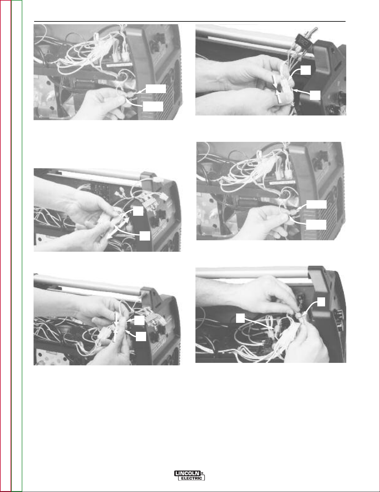
ELECTRICAL CONNECTIONS
P7
J3
10. Connect harness P7 (10-pin) to board J3 (10-
pin).
8. Adapter harness. All 6 connections shown are
used, and each one is unique.
(Proceed as follows)
P3
J3
9.A. Remove P3 (10-pin) from board J3 (10-pin).
P3
J7
IF MACHINE DOES NOT HAVE OPTIONAL SPOT TIMER.
(11.A. thru 11.D.)
P5
J5
11.A. Remove P5 (6-pin) from board J5 (6-pin).
J8
P5
Return to Section TOC Return to Section TOC Return to Section TOC Return to Section TOC
9.B. Connect P3 (10-pin) to harness J7 (10-pin).
Return to Master TOC Return to Master TOC Return to Master TOC Return to Master TOC
11.B. Connect P5 (6-pin) to harness J8 (6-pin).
P8
J5
11.C. Connect harness P8 (6-pin) to board J5 (6-
pin).
COMPACT WIRE WELDERS
Page 35
C-11 C-11
ACCESSORIES
P8
544A
J9
543A
11.D. Find assembled pair of machine terminals
(leads 543A & 544A) and disconnect. Go to
step 13.
IF MACHINE DOES HAVE OPTIONAL SPOT TIMER.
(12.A. thru 12.D.)
J9
P5
12.A. Remove P5 (6-pin) from spot timer harness J9
(6-pin).
12.C. Connect adapter harness P8 (6-pin) to spot
timer harness J9 (6-pin).
544A
543A
12.D. Find assembled pair of machine terminals
(leads 543A & 544A) and disconnect.
Return to Section TOC Return to Section TOC Return to Section TOC Return to Section TOC
J8
P5
12.B. Connect P5 (6-pin) to adapter harness J8 (6-
pin).
Return to Master TOC Return to Master TOC Return to Master TOC Return to Master TOC
B
A
13. Connect terminals:
(A) connect machine male (lead 543A) to adapter
harness female (lead 543A).
(B) connect machine female (lead 544A) to
adapter harness male (lead 544A).
14. Ensure that the locking tabs on all connectors
are latched closed.
COMPACT WIRE WELDERS
Page 36

C-12 C-12
ACCESSORIES
MOUNTING THE SWITCH
is fully seated into smaller hole.
19. Reinstall mounting nut onto switch.
15. Remove the plug button from the panel hole.
16. Plug button is no longer needed. Discard.
17, Remove mounting nut from switch. Keep mount-
ing nut for installation.
18. Install switch into panel hole. Ensure washer tab
Wrench tighten.
RE-ASSEMBLE MACHINE AS FOLLOWS:
20. Reinstall screw into plastic handle (if so
equipped).
21. Reinstall cover.
22. Reinstall door.
23. Reconnect input power to the machine
Return to Section TOC Return to Section TOC Return to Section TOC Return to Section TOC
Return to Master TOC Return to Master TOC Return to Master TOC Return to Master TOC
COMPACT WIRE WELDERS
Page 37

C-13 C-13
ACCESSORIES
ROUTINE WELDING MACHINE
PREPARATION
WARNING
ELECTRIC SHOCK CAN KILL.
1. Disconnect input power to the machine.
------------------------------------------------------------------------
2. Machine polarity setting: Set to DC electrode positive polarity per the machine’s Instruction Manual.
3. Gas selection and flow rate: Connect 100% welding
grade argon gas supply to the machine’s gas solenoid valve. Set the supply regulator to deliver a gas
flow rate of 20 to 50 SCFH thru the spool gun.]
4. Flip the machine’s wire drive selector switch (behind
the access door) to "Magnum 100SG". (See Figure
C.4)
FIGURE C.4
Return to Section TOC Return to Section TOC Return to Section TOC Return to Section TOC
PREPARING THE SPOOL GUN
WARNING
ELECTRIC SHOCK CAN KILL.
1. Disconnect input power to the machine.
------------------------------------------------------------------------
2. The Conical Spring is used as the spool brake only
when feeding the stronger and harder aluminum
alloy 5356. The Conical Spring must be removed
from the spool gun whenever using the softer aluminum alloy 4043.
Return to Master TOC Return to Master TOC Return to Master TOC Return to Master TOC
COMPACT WIRE WELDERS
Page 38

C-14 C-14
ACCESSORIES
LOADING ALUMINUM WIRE
1. Remove gas cone and contact tip. Remove spool
cover by unscrewing captive locking knob.
FIGURE C.5
2. Remove locking knob from spindle bolt by unscrewing it.
FIGURE C.6
4. Extend approximately 12 inches of wire from spool.
Straighten it out by back-bending it. Use care to
prevent the wire from dereeling.
FIGURE C.8
5. Cut off bent end of wire, leaving straight section.
FIGURE C.9
Return to Section TOC Return to Section TOC Return to Section TOC Return to Section TOC
3. Select wire alloy and diameter needed. Alloy 4043
and 0.035 wire size shown. Remove packaging and
data sheet from wire spool.
FIGURE C.7
Size
Alloy
Return to Master TOC Return to Master TOC Return to Master TOC Return to Master TOC
6. Gently pull open the idle roll assembly to expose the
drive roll groove.
FIGURE C.10
COMPACT WIRE WELDERS
Page 39

C-15 C-15
ACCESSORIES
7. Guide straightened wire through inlet wire guide
and toward drive roll groove.
FIGURE C.11
8. While holding open the idle roll, slide end of wire
through drive roll’s groove and toward gun tube liner.
FIGURE C.12
10a. Alloy 4043: Roll up remaining wire back onto
spool and place spool onto gun spindle. Install
locking knob and finger-tighten. Go to step 11.
FIGURE C.14
10b. Alloy 5356: Install Conical Spring, small end first,
onto gun spindle (A). Roll up remaining wire back
onto spool and place spool onto gun spindle.
Install locking knob and finger-tighten.
Go to step 11.
FIGURE C.15
9. Slide the wire into the liner until it extends approxi-
mately 1 inch beyond the end of the gas diffuser.
Release idle roll tab without snapping it.
FIGURE C.13
A
11. Grasp the free end of the wire at the gas diffuser
and slowly pull approximately 12 to 24 inches of
wire through the spool gun. There should only be 1
to 2 lbs. of resistance. If force is greater than 2 lbs.
wire is binding in the gun (also see Troubleshooting
guide).
FIGURE C.16
Return to Section TOC Return to Section TOC Return to Section TOC Return to Section TOC
Return to Master TOC Return to Master TOC Return to Master TOC Return to Master TOC
COMPACT WIRE WELDERS
Page 40

C-16 C-16
ACCESSORIES
12. Cut off excess wire 1 to 2 inches from gas diffuser.
Install properly-sized contact tip slightly past handtight. Install gas cone and hand-tighten.
FIGURE C.17
13. Reinstall spool cover. 1: tuck cover’s tab in place at
arrow and hold with thumb. 2: swing cover closed.
3: finger-tighten locking knob. 4: check for uniform
fit all around cover.
CONNECTING THE GUN TO THE
WELDING MACHINE
1. Disconnect input power to the machine.
2. Make sure that the gun locking knob is loosened.
(See Figure C.20).
3. Fully insert gun cable connection (welding power
and gas supply) into machine. Note that the master
Key way for P6 connector is located at the arrow.
FIGURE C.19
P6
Connector
Key way
FIGURE C.18
4. Check that the cable connector’s end is flush with
insulator at A. Tighten gun locking knob (B) onto
cable connector.
FIGURE C.20
4
1
3
2
A
B
Return to Section TOC Return to Section TOC Return to Section TOC Return to Section TOC
Return to Master TOC Return to Master TOC Return to Master TOC Return to Master TOC
COMPACT WIRE WELDERS
Page 41

D-1 D-1
Maintenance . . . . . . . . . . . . . . . . . . . . . . . . . . . . . . . . . . . . . . . . . . . . . . . . . . . . . . . . . . . . . . . . . . . . . . . . . . .D-1
Safety Precautions . . . . . . . . . . . . . . . . . . . . . . . . . . . . . . . . . . . . . . . . . . . . . . . . . . . . . . . . . . . . . . . . . . . .D-2
Routine Maintenance . . . . . . . . . . . . . . . . . . . . . . . . . . . . . . . . . . . . . . . . . . . . . . . . . . . . . . . . . . . . . . . . . .D-2
Gun & Cable Maintenance, Overload Protection . . . . . . . . . . . . . . . . . . . . . . . . . . . . . . . . . . . . . . . . . . . . .D-3
Changing Liner, Gun Handle Parts . . . . . . . . . . . . . . . . . . . . . . . . . . . . . . . . . . . . . . . . . . . . . . . . . . . . . . .D-4
Major Component Location . . . . . . . . . . . . . . . . . . . . . . . . . . . . . . . . . . . . . . . . . . . . . . . . . . . . . . . . . . . . .D-5
TABLE OF CONTENTS - MAINTENANCE SECTION
Return to Master TOC Return to Master TOC Return to Master TOC Return to Master TOC
COMPACT WIRE WELDERS
Page 42

D-2 D-2
MAINTENANCE
MAINTENANCE
SAFETY PRECAUTIONS
WARNING
ELECTRIC SHOCK can kill.
• Disconnect input power by removing
plug from receptacle before working
inside thr Compact Wire Welders. Use
only grounded receptacle. Do not touch
electrically “hot” parts inside the
machine.
• Have qualified personnel do the maintenance and trouble shooting work.
---------------------------------------------------------------------------------
ROUTINE MAINTENANCE
POWER SOURCE COMPARTMENT
No user serviceable parts inside! Do not attempt to perform
service in the power source (fixed) side of the COMPACT EIRE
WELDERS. Take the unit to an authorized Lincoln Service
Center if you experience problems.
TYPCALLY, No regular maintenance is required. In extremely
dusty locations, dirt may clog the air passages causing the
welder to run hot with premature tripping of thermal protection.
If so, blow dirt out of the welder with low pressure air at regular
intervals to eliminate excessive dirt and dust build-up on internal parts.
WIRE FEED COMPARTMENT
1. When necessary, vacuum accumulated dirt from gearbox
and wire feed section.
2. Occasionally inspect the wire guides and keep grooves
clean.
3. Motor and gearbox have lifetime lubrication and require no
maintenance.
FAN MOTOR
Has lifetime lubrication — requires no maintenance.
Return to Section TOC Return to Section TOC Return to Section TOC Return to Section TOC
WIRE REEL SPINDLE
Requires no maintenance. Do not lubricate shaft.
Return to Master TOC Return to Master TOC Return to Master TOC Return to Master TOC
COMPACT WIRE WELDERS
Page 43

D-3 D-3
MAINTENANCE
GUN AND CABLE
MAINTENANCE
FOR MAGNUM™ 100L GUN
Gun Cable Cleaning
Clean cable liner after using approximately 300 lbs
(136 kg) of solid wire or 50 lbs (23 kg) of flux-cored
wire. Remove the cable from the wire feeder and lay it
out straight on the floor. Remove the contact tip from
the gun. Using low pressure air, gently blow out the
cable liner from the gas diffuser end.
CAUTION
Excessive pressure at the start may cause the dirt
to form a plug.
Flex the cable over its entire length and again blow out
the cable. Repeat this procedure until no further dirt
comes out.
Contact Tips, Nozzles, and Gun Tubes
1. Dirt can accumulate in the contact tip hole and
restrict wire feeding. After each spool of wire is
used, remove the contact tip and clean it by pushing a short piece of wire through the tip repeatedly.
Use the wire as a reamer to remove dirt that may be
adhering to the wall of the hole through the tip.
2. Replace worn contact tips as required. A variable or
“hunting” arc is a typical symptom of a worn contact
tip. To install a new tip, choose the correct size contact tip for the electrode being used (wire size is
stenciled on the side of the contact tip) and screw it
snugly into the gas diffuser.
5. To remove gun tube from gun, remove gas nozzle
or gasless nozzle and remove diffuser from gun
tube. Remove both collars from each end of the
gun handle and separate the handle halves.
Loosen the locking nut holding the gun tube in
place against the gun end cable connector.
Unscrew gun tube from cable connector. To install
gun tube, screw the locking nut on the gun tube as
far as possible. Then screw the gun tube into the
cable connector until it bottoms. Then unscrew (no
more than one turn) the gun tube until its axis is
perpendicular to the flat sides of the cable connector and pointed in the direction of the trigger.
Tighten the locking nut so as to maintain the proper relationship between the gun tube and the cable
connector. Replace the gun handle, trigger and diffuser. Replace the gas nozzle or gasless nozzle.
OVERLOAD PROTECTION
Output Overload
The Compact Wire Welders are equipped with a circuit
breaker and a thermostat which protects the machine
from damage if maximum output is exceeded. The circuit breaker button will extend out when tripped. The
circuit breaker must be manually reset.
Thermal Protection
The Compact Wire Welders have a rated output duty
cycle as defined in the Technical Specification pages.
If the duty cycle is exceeded, a thermal protector will
shut off the output until the machine cools to a reasonable operating temperature. This is an automatic
function of the machine and does not require user
intervention. The fan continues to run during cooling.
Return to Section TOC Return to Section TOC Return to Section TOC Return to Section TOC
3. Remove spatter from inside of gas nozzle and from
tip after each 10 minutes of arc time or as required.
4. Be sure the gas nozzle is fully screwed onto the diffuser for gas shielded processes. For the
Innershield®process, the gasless nozzle should
screw onto the diffuser.
Return to Master TOC Return to Master TOC Return to Master TOC Return to Master TOC
Electronic Wire Drive Motor Protection
The Compact Wire Welders have built-in protection
against wire drive motor overload. If the motor current
limit is exceded the trigger circuit is interupted and the
weld stops.
COMPACT WIRE WELDERS
Page 44
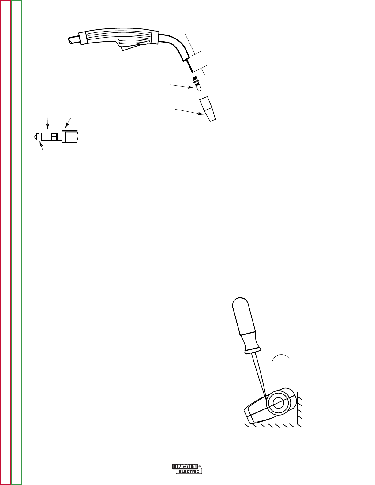
D-4 D-4
Set Screw Brass Cable
Connector
Liner Assembly
(Liner bushing to be sealed tight
against brass cable connector)
FIGURE D.2
Liner trim length
MAINTENANCE
1-1/4”(31.8 mm)
Liner Trim Length
Gas Diffuser
Gas Nozzle or
Gasless Nozzle
8. Screw the gas diffuser onto the end of the gun tube
and securely tighten.
CHANGING LINER
9. Replace the contact tip and nozzle.
NOTICE: The variation in cable lengths prevents the
interchangeability of liners. Once a liner has been cut
for a particular gun, it should not be installed in another gun unless it can meet the liner cutoff length requirement. Refer to Figure D.2.
1. Remove the gas nozzle from the gun by unscrewing
counter-clockwise.
2. Remove the existing contact tip from the gun by
unscrewing counter-clockwise.
3. Remove the gas diffuser from the gun tube by
unscrewing counter-clockwise.
GUN HANDLE PARTS
The gun handle consists of two halves that are held
together with a collar on each end. To open up the handle, turn the collars approximately 60 degrees counterclockwise until the collar reaches a stop. Then pull the
collar off the gun handle. If the collars are difficult to
turn, position the gun handle against a corner, place a
screwdriver against the tab on the collar and give the
screwdriver a sharp blow to turn the collar past an
internal locking rib. See Figure D-3.
Return to Section TOC Return to Section TOC Return to Section TOC Return to Section TOC
4. Lay the gun and cable out straight on a flat surface.
Loosen the set screw located in the brass connector
at the wire feeder end of the cable. Pull the liner out
of the cable.
5. Insert a new untrimmed liner into the connector end
of the cable. Be sure the liner bushing is stenciled
appropriately for the wire size being used.
6. Fully seat the liner bushing into the connector.
Tighten the set screw on the brass cable connector.
At this time, the gas diffuser should not be installed
onto the end of the gun tube.
7. With the gas nozzle and diffuser removed from the
gun tube, be sure the cable is straight, and then trim
the liner to the length shown in the Figure D.2.
Remove any burrs from the end of the liner.
Return to Master TOC Return to Master TOC Return to Master TOC Return to Master TOC
„
Counter-clockwise
FIGURE D.3
COMPACT WIRE WELDERS
Page 45

D-5 D-5
55
33
22
11
44
MAINTENANCE
MAJOR COMPONENT LOCATIONS
1. Case Front, Back and Bottom Assembly
2. Power Module Assembly
3. Center Panel Assembly
4. Wire Drive Assembly
5. Wraparound & Door Assembly
Return to Section TOC Return to Section TOC Return to Section TOC Return to Section TOC
Return to Master TOC Return to Master TOC Return to Master TOC Return to Master TOC
COMPACT WIRE WELDERS
Page 46

D-6 D-6
55
44
11
22
33
MAINTENANCE
MAJOR COMPONENT LOCATIONS
1. Case Front Assembly
2. Wire Drive Assembly
3. Center Panel Assembly
4. Power Module and Base Assembly
5. Wraparound & Door Assembly
Return to Section TOC Return to Section TOC Return to Section TOC Return to Section TOC
Return to Master TOC Return to Master TOC Return to Master TOC Return to Master TOC
COMPACT WIRE WELDERS
Page 47

E-1 E-1
TRIGGER
RECEPTACLE
WIRE
SPEED
CONTROL
ARC
VOLTAGE
CONTROL
CONTROL
BOARD
GAS
SOLENOID
WIRE
FEED
MOTOR
LINE
SWITCH
CIRCUIT
BREAKER
INPUT
RECEPTACLE
FAN
MOTOR
MAIN
TRANSFORMER
MAIN
BRIDGE
CHOKE
+
+
-
OUTPUT
TERMINALS
VOLTAGE FEEDBACK &
MOTOR POWER
TABLE OF CONTENTS-THEORY OF OPERATION SECTION
Theory of Operation . . . . . . . . . . . . . . . . . . . . . . . . . . . . . . . . . . . . . . . . . . . . . . . . . . . . . . . . . . . . . . . . . . . . .E-1
General Description . . . . . . . . . . . . . . . . . . . . . . . . . . . . . . . . . . . . . . . . . . . . . . . . . . . . . . . . . . . . . . . . . . .E-2
Input Power . . . . . . . . . . . . . . . . . . . . . . . . . . . . . . . . . . . . . . . . . . . . . . . . . . . . . . . . . . . . . . . . . . . . . . . . .E-3
Output Control, Rectification & Voltage Feedback . . . . . . . . . . . . . . . . . . . . . . . . . . . . . . . . . . . . . . . . . . . .E-4
Trigger, Gas Solenoid & Wire Drive . . . . . . . . . . . . . . . . . . . . . . . . . . . . . . . . . . . . . . . . . . . . . . . . . . . . . . .E-5
SCR Operation . . . . . . . . . . . . . . . . . . . . . . . . . . . . . . . . . . . . . . . . . . . . . . . . . . . . . . . . . . . . . . . . . . . . . . .E-6
Thermal Protection, Output Overload & Electronic Wire Drive Motor Protection . . . . . . . . . . . . . . . . . . . .E-7
FIGURE E.1 — BLOCK LOGIC DIAGRAM.
Return to Master TOC Return to Master TOC Return to Master TOC Return to Master TOC
COMPACT WIRE WELDERS
Page 48

E-2 E-2
TRIGGER
RECEPTACLE
WIRE
SPEED
CONTROL
ARC
VOLTAGE
CONTROL
CONTROL
BOARD
GAS
SOLENOID
WIRE
FEED
MOTOR
LINE
SWITCH
CIRCUIT
BREAKER
INPUT
RECEPTACLE
FAN
MOTOR
MAIN
TRANSFORMER
MAIN
BRIDGE
CHOKE
+
+
-
OUTPUT
TERMINALS
VOLTAGE FEEDBACK &
MOTOR POWER
THEORY OF OPERATION
FIGURE E.2 — GENERAL DESCRIPTION
GENERAL DESCRIPTION
The Compact Wire Welders that are covered by this
manual are Constant Voltage (CV) DC welders that
can be used for MIG or Flux-Core process . The 120
VAC machines are rated for 90 amps, 19.5 volts, at
20% duty cycle. The 208 / 230 VAC machines are
rated for 130 amps, 17 / 20 volts, at a 30% duty
cycle. All are equipped with a 4-pin trigger connector to allow operation of an optional spool gun for
Aluminum MIG Welding.
Return to Section TOC Return to Section TOC Return to Section TOC Return to Section TOC
Return to Master TOC Return to Master TOC Return to Master TOC Return to Master TOC
NOTE: Unshaded areas of Block Logic
Diagram are the subject of discussion
COMPACT WIRE WELDERS
Page 49

E-3 E-3
TRIGGER
RECEPTACLE
WIRE
SPEED
CONTROL
ARC
VOLTAGE
CONTROL
CONTROL
BOARD
GAS
SOLENOID
WIRE
FEED
MOTOR
LINE
SWITCH
CIRCUIT
BREAKER
INPUT
RECEPTACLE
FAN
MOTOR
MAIN
TRANSFORMER
MAIN
BRIDGE
CHOKE
+
+
-
OUTPUT
TERMINALS
VOLTAGE FEEDBACK &
MOTOR POWER
THEORY OF OPERATION
FIGURE E.3 — INPUT POWER CIRCUITS
INPUT LINE VOLTAGE, FAN MOTOR
& MAIN TRANSFORMER
A circuit breaker is incorporated in the circuit to protect
the unit from current overloads.
The main transformer receives the primary voltage
from the Control Board and changes that high voltage
and low current input power to a low voltage and high
current output suitable for welding.
The fan motor is rated for the same AC Voltage as the
welder and should run whenever the machine is Power
Switch is turned ON.
Return to Section TOC Return to Section TOC Return to Section TOC Return to Section TOC
Return to Master TOC Return to Master TOC Return to Master TOC Return to Master TOC
NOTE: Unshaded areas of Block Logic
Diagram are the subject of discussion
COMPACT WIRE WELDERS
Page 50

E-4 E-4
TRIGGER
RECEPTACLE
WIRE
SPEED
CONTROL
ARC
VOLTAGE
CONTROL
CONTROL
BOARD
GAS
SOLENOID
WIRE
FEED
MOTOR
LINE
SWITCH
CIRCUIT
BREAKER
INPUT
RECEPTACLE
FAN
MOTOR
MAIN
TRANSFORMER
MAIN
BRIDGE
CHOKE
+
+
-
OUTPUT
TERMINALS
VOLTAGE FEEDBACK &
MOTOR POWER
THEORY OF OPERATION
FIGURE E.4 — OUTPUT CIRCUITS
OUTPUT CONTROL,
RECTIFICATION & VOLTAGE
FEEDBACK
The AC voltage that is applied to the main transformer
primary is controlled at the control board by two SCRs
(Silicon Controlled Rectifiers). The SCRs are controlled
by a pulse signal developed on the control board. The
control board compares the commands of the arc voltage control with the voltage feedback signal. (The Arc
Voltage Control may be either a continuous control or
a selector switch, depending on the model of the
machine).
The board circuitry then sends a pulse to turn on the
SCRs. In this manner, the voltage applied to the primary of the transformer is varied and controlled. This
controlled voltage is reflected at the transformer secondary winding and is applied to the rectifier diode
bridge. This rectified DC voltage is filtered by the output capacitor and choke circuit and is applied to the
machine’s output terminals.
Return to Section TOC Return to Section TOC Return to Section TOC Return to Section TOC
Return to Master TOC Return to Master TOC Return to Master TOC Return to Master TOC
NOTE: Unshaded areas of Block Logic
Diagram are the subject of discussion
COMPACT WIRE WELDERS
Page 51

E-5 E-5
TRIGGER
RECEPTACLE
WIRE
SPEED
CONTROL
ARC
VOLTAGE
CONTROL
CONTROL
BOARD
GAS
SOLENOID
WIRE
FEED
MOTOR
LINE
SWITCH
CIRCUIT
BREAKER
INPUT
RECEPTACLE
FAN
MOTOR
MAIN
TRANSFORMER
MAIN
BRIDGE
CHOKE
+
+
-
OUTPUT
TERMINALS
VOLTAGE FEEDBACK &
MOTOR POWER
THEORY OF OPERATION
FIGURE E.5 — TRIGGER, GAS SOLENOID & WIRE DRIVE
TRIGGER, GAS SOLENOID AND
WIRE DRIVE
Closure of the trigger circuit (pulling the gun trigger)
signals the control board to start several functions. A
DC is applied to the gas solenoid (if present) to allow
shielding gas to flow if required. The SCRs are activated and voltage is applied to the main transformer.
The output voltage that is developed at the output terminals is also fed back to the control board to facilitate
control of the output and also to power the Wire feed
Motor circuitry.
The voltage that powers the wire drive motor is varied
and controlled on the control board in response to the
setting of the Wire Speed Control. The control board
monitors the drive motor armature current and voltage
and compares the feedback information with the commands sent from the wire speed control to maintain a
constant wire speed.
The Control Board also has an automatic protection
circuit, which shuts off the trigger circuit in the event of
a wire drive motor overload.
Return to Section TOC Return to Section TOC Return to Section TOC Return to Section TOC
Return to Master TOC Return to Master TOC Return to Master TOC Return to Master TOC
NOTE: Unshaded areas of Block Logic
Diagram are the subject of discussion
COMPACT WIRE WELDERS
Page 52

E-6 E-6
INPUT
OUTPUT
CATHODE
ANODE
GATE
NOTE: AS THE GATE
PULSE IS APPLIED
LATER IN THE CYCLE
THE SCR OUTPUT
IS DECREASED.
THEORY OF OPERATION
SCR OPERATION
A silicon controlled rectifier (SCR) is a three terminal
device used to control large currents to a load. An
SCR acts very much like a switch. When it is turned
on, there is current flow from anode to cathode. In the
ON state, the SCR acts like a closed switch. When the
SCR is turned OFF, there is no current flow from anode
to cathode, thus the device acts like an open switch.
As the name suggests, the SCR is a rectifier, so it
passes current only during positive half cycles of the
AC supply. The positive half cycle is the portion of the
sine wave in which the anode of the SCR is more positive than the cathode.
When an AC supply voltage is applied to the SCR, the
device spends a certain portion of the AC cycle time in
the ON state, and a remainder of the time in the OFF
state. The gate controls the amount of time spent in
each state.
FIGURE E.6 — SCR OPERATION
An SCR is fired by a short burst of current into the gate.
This gate pulse must be more positive than the cathode voltage. Since there is a standard PN junction
between gate and cathode, the voltage between these
terminals must be slightly greater than 0.6V. Once the
SCR has fired, it is not necessary to continue the flow
of the gate current. As long as current continues to
flow from anode to cathode, the SCR will remain on.
When the anode to cathode current drops below a minimum value, called holding current, the SCR will shut
off. This normally occurs as the AC voltage passes
through zero into the negative portion of the sine wave.
If the SCR is turned on early in the positive half cycle,
the conduction time is longer, resulting in greater SCR
output. If the gate firing occurs later in the cycle, the
conduction time is less, resulting in lower SCR output.
Return to Section TOC Return to Section TOC Return to Section TOC Return to Section TOC
Return to Master TOC Return to Master TOC Return to Master TOC Return to Master TOC
COMPACT WIRE WELDERS
Page 53

E-7 E-7
THERMAL PROTECTION
The Compact Wire Welders have a rated output duty
cycle as defined in the Technical Specification page. If
the duty cycle is exceeded, a thermal protector will shut
off the output until the machine cools to a reasonable
operating temperature. This is an automatic function of
and does not require user intervention. The fan continues to run during cooling. If the fan is not turning or the
air intake louvers become obstructed, the input power
must then be removed and the fan problem or air
obstruction corrected.
OUTPUT OVERLOAD
The Compact Wire Welders are equipped with a circuit
breaker which protects the machine from damage if
maximum output is exceeded. The circuit breaker must
be manually reset.
ELECTRONIC WIRE DRIVE MOTOR PROTECTION
The Compact Wire Welders built-in protection for wire
drive motor overload.
THEORY OF OPERATION
Return to Section TOC Return to Section TOC Return to Section TOC Return to Section TOC
Return to Master TOC Return to Master TOC Return to Master TOC Return to Master TOC
COMPACT WIRE WELDERS
Page 54

E-8 E-8
NOTES
Return to Section TOC Return to Section TOC Return to Section TOC Return to Section TOC
Return to Master TOC Return to Master TOC Return to Master TOC Return to Master TOC
COMPACT WIRE WELDERS
Page 55

F-1 F-1
Troubleshooting and Repair . . . . . . . . . . . . . . . . . . . . . . . . . . . . . . . . . . . . . . . . . . . . . . . . . . . . . . . . . . . . . .F-1
TABLE OF CONTENTS - TROUBLESHOOTING & REPAIR
How to Use Troubleshooting Guide . . . . . . . . . . . . . . . . . . . . . . . . . . . . . . . . . . . . . . . . . . . . . . . . . . . . . . .F-2
PC Board Troubleshooting Procedures . . . . . . . . . . . . . . . . . . . . . . . . . . . . . . . . . . . . . . . . . . . . . . . . . . . .F-3
Troubleshooting Guide . . . . . . . . . . . . . . . . . . . . . . . . . . . . . . . . . . . . . . . . . . . . . . . . . . . . . . . . . . . . . . . . .F-4
Test Procedures . . . . . . . . . . . . . . . . . . . . . . . . . . . . . . . . . . . . . . . . . . . . . . . . . . . . . . . . . . . . . . . . . . . . .F-11
Case Cover Removal and Replacement . . . . . . . . . . . . . . . . . . . . . . . . . . . . . . . . . . . . . . . . . . . . . . . . . .F-11
Gas Solenoid Test . . . . . . . . . . . . . . . . . . . . . . . . . . . . . . . . . . . . . . . . . . . . . . . . . . . . . . . . . . . . . . . .F-13
Wire Drive Test . . . . . . . . . . . . . . . . . . . . . . . . . . . . . . . . . . . . . . . . . . . . . . . . . . . . . . . . . . . . . . . . . . .F-15
Main Transformer Test . . . . . . . . . . . . . . . . . . . . . . . . . . . . . . . . . . . . . . . . . . . . . . . . . . . . . . . . . . . . .F-17
Fan Motor Test . . . . . . . . . . . . . . . . . . . . . . . . . . . . . . . . . . . . . . . . . . . . . . . . . . . . . . . . . . . . . . . . . . F-21
Typical Output Voltage Waveform - Machine Loaded . . . . . . . . . . . . . . . . . . . . . . . . . . . . . . . . . . . . . . . .F-23
Abnormal Open Circuit Voltage Waveform . . . . . . . . . . . . . . . . . . . . . . . . . . . . . . . . . . . . . . . . . . . . . . . . .F-24
Control Board Removal and Replacement . . . . . . . . . . . . . . . . . . . . . . . . . . . . . . . . . . . . . . . . . . . . . . . .F-25
Power Module Removal and Replacement . . . . . . . . . . . . . . . . . . . . . . . . . . . . . . . . . . . . . . . . . . . . . . . .F-29
Rectifier, Transformer, Choke Assembly & Capacitor Removal and Replacement . . . . . . . . . . . . . . . . . .F-33
Wire Drive Motor Removal and Replacement . . . . . . . . . . . . . . . . . . . . . . . . . . . . . . . . . . . . . . . . . . . . . .F-39
Fan Motor Removal and Replacement . . . . . . . . . . . . . . . . . . . . . . . . . . . . . . . . . . . . . . . . . . . . . . . . . . .F-43
Retest After Repair . . . . . . . . . . . . . . . . . . . . . . . . . . . . . . . . . . . . . . . . . . . . . . . . . . . . . . . . . . . . . . . . .F-47/48
Return to Master TOC Return to Master TOC Return to Master TOC Return to Master TOC
COMPACT WIRE WELDERS
Page 56

F-2 F-2
TROUBLESHOOTING & REPAIR
HOW TO USE TROUBLESHOOTING GUIDE
WARNING
Service and Repair should only be performed by Lincoln Electric Factory Trained
Personnel. Unauthorized repairs performed on this equipment may result in danger to
the technician and machine operator and will invalidate your factory warranty. For your
safety and to avoid Electrical Shock, please observe all safety notes and precautions
detailed throughout this manual.
---------------------------------------------------------------------------------------------------------------------------
This Troubleshooting Guide is provided to
help you locate and repair possible machine
malfunctions. Simply follow the three-step
procedure listed below.
Step 1. LOCATE PROBLEM (SYMPTOM).
Look under the column labeled “PROBLEM
(SYMPTOMS)”. This column describes possible symptoms that the machine may exhibit. Find the listing that best describes the
symptom that the machine is exhibiting.
Symptoms are grouped into the following
categories: output problems, function problems, wire feeding problems, and welding
problems.
Step 2. PERFORM EXTERNAL TESTS.
The second column labeled “POSSIBLE
AREAS OF MISADJUSTMENT(S)” lists the
obvious external possibilities that may contribute to the machine symptom. Perform
these tests/checks in the order listed. In
general, these tests can be conducted without removing the case wrap-around cover.
Step 3. RECOMMENDED
COURSE OF ACTION
The last column labeled “Recommended
Course of Action” lists the most likely components that may have failed in your
machine. It also specifies the appropriate
test procedure to verify that the subject component is either good or bad. If there are a
number of possible components, check the
components in the order listed
one possibility at a time until you locate the
cause of your problem.
All of the referenced test procedures
referred to in the Troubleshooting Guide are
described in detail at the end of this chapter.
Refer to the Troubleshooting and Repair
Table of Contents to locate each specific
Test Procedure. All of the specified test
points, components, terminal strips, etc. can
be found on the referenced electrical wiring
diagrams and schematics. Refer to the
Electrical Diagrams Section Table of
Contents to locate the appropriate diagram.
to eliminate
Return to Section TOC Return to Section TOC Return to Section TOC Return to Section TOC
CAUTION
If for any reason you do not understand the test procedures or are unable to perform the
tests/repairs safely, contact the Lincoln Electric Service Department for technical troubleshooting
assistance before you proceed. Call 1-888-935-3877.
-----------------------------------------------------------------------------------------------------------------------------------
Return to Master TOC Return to Master TOC Return to Master TOC Return to Master TOC
COMPACT WIRE WELDERS
Page 57

F-3 F-3
TROUBLESHOOTING & REPAIR
PC BOARD TROUBLESHOOTING PROCEDURES
WARNING
ELECTRIC SHOCK
can kill.
•
Have an electrician install and
service this equipment. Turn the
input power OFF at the fuse box
before working on equipment. Do
not touch electrica lly hot parts.
CAUTION
Sometimes machine failures appear to be due to PC
board failures. These problems can sometimes be
traced to poor electrical connections. To avoid problems when troubleshooting and replacing PC boards,
please use the following procedure:
1. Determine to the best of your technical ability
that the PC board is the most likely component
causing the failure symptom.
2. Check for loose connections at the PC board
to assure t h a t the P C board i s properly
connected.
3. If the problem persists, replace the suspect PC
board using standard practices to avoid static
electrical damage and electrical shock. Read
the warning inside the static resistant bag and
perform the following procedures:
PC board can be damaged by static electricity.
- Remove your b o d y ’s s t a t i c
charge before opening the staticshielding bag. Wear an anti-static
wrist s trap. For safe ty, u se a 1
Meg ohm resistive cord connected
ATTENTION
Static-Sensitive
Devices
Handle only at
Static-Safe
Workstations
to a grounded part of the
equipment frame.
- If you don’t have a wrist strap,
touch an un-pai nted, grounded,
part of the equipment frame. Keep
touching t he fr a m e to pr e v e n t
static build-up. B e sure not to
touch any electrically live parts at
the same time.
- Remove the PC board from the static-shielding bag
and place it directly into the equipment. Don’t set the
PC board on or near paper, plastic or cloth which
could have a static charge. If the PC board can’t be
installed immediately, put it back in the static-shielding bag.
- If the PC board uses protective shorting jumpers,
don’t remove them until installation is complete.
- If you return a PC board to The Lincoln Electric
Company for credit, it must be in the static-shielding
bag. This will prevent further damage and allow proper failure analysis.
4. Test the machine to determine if the failure
symptom has been corrected by t h e
replacement PC board.
NOTE: It is desirable to have a spare (known good)
PC board available for PC board troubleshooting.
NOTE: Allow the machine to heat up so that all
elect rical components can re ach their operating
temperature.
5. Remove t h e replacement PC b o a r d and
substitute i t w i t h the original PC b o a r d to
recreate the original problem.
a. If the original problem does not reappear by
substituting the original board, then the PC
board was not the problem. Continue to look
for bad connections in the con trol wi ring
harness, junction blocks, and terminal strips.
b. If the original problem is recreated by the
substitution of the original board, then the PC
board w a s t h e p r o b l e m . R e i n s t a l l the
replacement PC board and test the machine.
6. Always i n d i c a t e that this p r o c e d u r e was
followed when warranty reports are to b e
submitted.
NOTE: Following this procedure and writing on the
warranty report, “INSTALLED AND SWITCHED PC
BOARDS TO VERIFY PROBLEM,” will help avoid
denial of legitimate PC board warranty claims.
Return to Section TOC Return to Section TOC Return to Section TOC Return to Section TOC
- Tools which come in contact with the PC board must
be either conductive, anti-static or static-dissipative.
Return to Master TOC Return to Master TOC Return to Master TOC Return to Master TOC
COMPACT WIRE WELDERS
Page 58
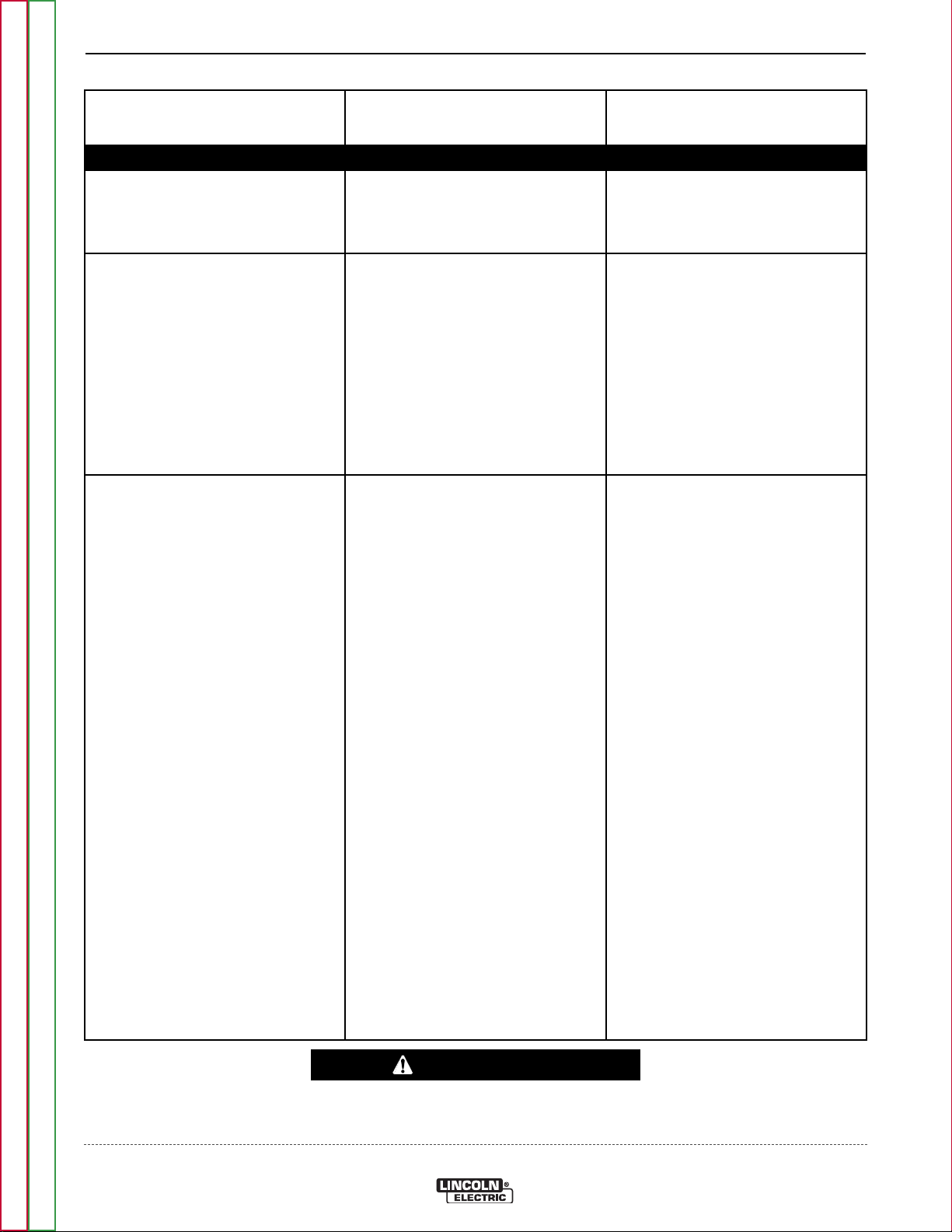
F-4 F-4
Observe Safety Guidelines detailed in the beginning of this manual.
TROUBLESHOOTING & REPAIR
PROBLEMS
(SYMPTOMS)
Major physical or electrical damage is evident.
Machine is dead - no open circuit voltage, wire feed, gas flow when trigger is pulled and fan does not operate.
No weld output, wire feed, gas flow when the trigger is pulled. Fan does run.
POSSIBLE AREAS OF
MISADJUSTMENT(S)
OUTPUT PROBLEMS
1. Contact your local Lincoln
Authorized Field Service
Facility.
1. Make sure correct voltage is
applied to the machine.
2. Make certain that the power
switch is in the “on” position.
3. Blown fuses in the input line.
Check circuit breaker on the
machine.
1. The thermostat may be open
due to machine overheating. If
machine operates normal after
a cooling off period then check
for proper fan ventilation,
remove any obstructions. Make
certain that the machine’s duty
cycle is not being exceeded.
2. Gun trigger may be faulty.
RECOMMENDED
COURSE OF ACTION
1. Contact the Lincoln Electric
Service Dept.
1-888-935-3877.
1. Check input power switch
(S1) it may be faulty. See
Wiring Diagram.
2. Check lead connection and
correct function of circuit
breaker. See Wiring
Diagram.
3. The Control P.C. Board may
be faulty
1. Check thermostat and
associated leads for loose or
broken connections. See
wiring diagram.
2. Remove main power supply to
the machine. With the gun
trigger pulled check for
continuity at pins 6 and 3 on
plug J5 on the control board.
Return to Section TOC Return to Section TOC Return to Section TOC Return to Section TOC
3. Perform the Transformer Test.
4. Check all heavy current
carrying leads. Check for loose
or broken connections at the
transformer, choke and
rectifier.
5. Make sure identity plug is not
missing on control board. See
Wiring Diagram.
6. Possible bad control board.
Replace.
CAUTION
If for any reason you do not understand the test procedures or are unable to perform the tests/repairs safely,
contact the Lincoln Electric Service Department for technical troubleshooting assistance before you proceed.
Call 1-888-935-3877.
Return to Master TOC Return to Master TOC Return to Master TOC Return to Master TOC
COMPACT WIRE WELDERS
Page 59

F-5 F-5
Observe Safety Guidelines detailed in the beginning of this manual.
TROUBLESHOOTING & REPAIR
PROBLEMS
(SYMPTOMS)
The machine has output, wire feed, gas flow but NO fan.
The machine has output, gas flow and fan but does not have wire drive.
No wire feed when gun trigger is
pulled. Fan runs, gas flows and
machine has correct open circuit
voltage. ( 33 vdc maximum) weld output.
POSSIBLE AREAS OF
MISADJUSTMENT(S)
OUTPUT/FEEDING PROBLEMS
1. Possible faulty fan motor.
2. Possible faulty Control P.C.
Board.
1. Possible bad drive motor.
2. Possible bad Control P.C.
Board.
1. If the wire drive motor is
running, make sure that the
correct drive roll and wire
guide is installed in the
machine.
2. Check for clogged cable liner
or contact tip.
RECOMMENDED
COURSE OF ACTION
1. Perform the Fan Motor Test.
2. Check for continuity between
#6 to Fan or #1 to Fan on
Control P.C. Board. Replace.
1. Perform the Wire Drive Test.
2. If 3 - 30 vdc is not at the drive
motor check for OCV at the
board on pins 1 and 10 on J3.
If OCV is present possible
faulty Control P.C Board.
Replace. If OCV is not
present check continuity of
wires CAP- and CAP+.
1. Perform the Wire Drive Test.
2. If wire drive test is OK, then
check for OCV at CAP- and
CAP+ on the control board. If
correct voltage is present,
possible faulty Control P.C.
Board. Replace.
Return to Section TOC Return to Section TOC Return to Section TOC Return to Section TOC
3. Check for proper size cable
liner and contact tip.
3. If open circuit voltage is not
present at CAP- and CAP+ on
control board check continuity
of leads.
CAUTION
If for any reason you do not understand the test procedures or are unable to perform the tests/repairs safely,
contact the Lincoln Electric Service Department for technical troubleshooting assistance before you proceed.
Call 1-888-935-3877.
Return to Master TOC Return to Master TOC Return to Master TOC Return to Master TOC
COMPACT WIRE WELDERS
Page 60

F-6 F-6
Observe Safety Guidelines detailed in the beginning of this manual.
TROUBLESHOOTING & REPAIR
PROBLEMS
(SYMPTOMS)
The machine stops feeding wire with trigger pulled. Re-trigger and machine starts feeding wire again.
1. Wire drive speed stays on one speed. No wire speed control.
POSSIBLE AREAS OF
MISADJUSTMENT(S)
FEEDING PROBLEMS
1. Check for adequate wire
supply.
2. Check for mechanical
restrictions in the wire feeding
path. The gun may be clogged.
3. Make sure the gun liner and
tip are correct for the wire size
being used.
4. Check spindle for ease of
rotation.
1. Possible faulty drive motor.
2. Possible faulty Control board.
RECOMMENDED
COURSE OF ACTION
1. Check the motor armature
current. If high (over 2.5
amps) and there are no
restrictions in the wire feeding
path, then the motor or gear
box may be faulty. Replace.
2. If motor armature current is
below 2.5 amps. The Control
P.C. board may be faulty.
Replace.
1. Remove main supply power to
the machine. Disconnect plug
J3 from the control board.
Test the resistance from lead
MOT- in the harness plug to
the wire feed motor case. If
resistance is below 500,000
ohms, replace the drive
motor.
CAUTION
2. If no voltage charge is seen
on MOT+ and MOT- when
turning wire speed
potentiometer, the Control
P.C. Board may be faulty.
Replace.
Return to Section TOC Return to Section TOC Return to Section TOC Return to Section TOC
If for any reason you do not understand the test procedures or are unable to perform the tests/repairs safely,
contact the Lincoln Electric Service Department for technical troubleshooting assistance before you proceed.
Call 1-888-935-3877.
Return to Master TOC Return to Master TOC Return to Master TOC Return to Master TOC
COMPACT WIRE WELDERS
Page 61

F-7 F-7
Observe Safety Guidelines detailed in the beginning of this manual.
TROUBLESHOOTING & REPAIR
PROBLEMS
(SYMPTOMS)
The arc is unstable - poor starting.
Low or no gas flow when gun trigger is pulled. Wire feed, weld output and fan operate normally.
POSSIBLE AREAS OF
MISADJUSTMENT(S)
WELDING PROBLEMS
1. Check for correct input voltage
to the machine.
2. Check for proper electrode
polarity for process.
3. Check gun tip for wear or
damage-Replace.
4. Check for proper gas and flow
rate for process.
5. Check work cable for loose or
faulty connections.
6. Check gun for damage or
breaks
GAS FLOW PROBLEMS
1. Check gas supply, flow
regulator and gas hoses.
2. Check gun connection to
machine for obstruction or
leaky seals.
RECOMMENDED
COURSE OF ACTION
1. Check for 17 to 33 VDC
(dependent on Arc Voltage
Control Setting) at the
machine’s output terminals. If
present check gun and work
cable.
2. If OCV is low, check output
capacitor and output diodes.
3. Check for loose connections
at the output terminals, the
choke and all heavy current
carrying leads. See Wiring
Diagram.
4. The Control P.C. Board may
be faulty. Replace.
1. Check the gas solenoid by
disconnecting it from the
control board and applying a
12 vdc external supply to the
gas solenoid. If solenoid does
not activate it may be faulty.
Replace.
Return to Section TOC Return to Section TOC Return to Section TOC Return to Section TOC
2. The control P.C. board may
be faulty. Replace.
CAUTION
If for any reason you do not understand the test procedures or are unable to perform the tests/repairs safely,
contact the Lincoln Electric Service Department for technical troubleshooting assistance before you proceed.
Call 1-888-935-3877.
Return to Master TOC Return to Master TOC Return to Master TOC Return to Master TOC
COMPACT WIRE WELDERS
Page 62

F-8 F-8
Observe Safety Guidelines detailed in the beginning of this manual.
TROUBLESHOOTING & REPAIR
PROBLEMS
(SYMPTOMS)
No wire feed occurs when Spool Gun trigger is pulled.
POSSIBLE AREAS OF
MISADJUSTMENT(S)
SPOOL GUN PROBLEMS
1. Machine is switched off or
unplugged.
2. Spool gun is out of wire
3. Contact tip burnback.
4. Fully or partially blocked gun
tube liner.
5. Bird nest.
6. Machine’s toggle selector
switch is not set to spool gun
mode.
7. Defective trigger. (contacts
open)
8. Defective trigger circuit in gun.
9. Damaged spool gun motor.
10. No motor voltage or current
from machine.
11. Contact tip size too small for
wire diameter used.
RECOMMENDED
COURSE OF ACTION
1. Switch on or plug in machine.
2. Install full spool of specified
wire.
3. Replace contact tip.
4. Replace and clean or replace
gun tube liner. ( See
Maintenance Section)
5. Cut out birds nest, reload
wire, and check for proper
wire alignment and wire’s
mechanical resistance.
6. Flip switch to proper
operating position.
7. Replace trigger. ( See
Maintenance Section).
8. Disconnect gun from machine
and check trigger for
continuity.
9. Contact LASF for possible
motor replacement.
Return to Section TOC Return to Section TOC Return to Section TOC Return to Section TOC
10. See Troubleshooting section
in welding machine’s
instruction manual.
11. Replace contact tip with one
that is the right size.
Sluggish wire feed when the Spool Gun trigger is pulled.
1. Drive roll is worn or galled with
aluminum.
2. Machine’s wire feed speed
setting is too low.
3. Wire is obstructed somewhere
along the wire feed path in the
gun.
4. Low motor voltage.
1. Clean drive roll of all
aluminum or replace drive
roll.
2. Increase wire feed speed.
3. Check for obstructions:
remove any wire shavings;
remove kinked wire; remove
and clean or replace gun tube
liner ( See Maintenance
Section).
4. See Troubleshooting section
in welding machine’s
instruction manual.
CAUTION
If for any reason you do not understand the test procedures or are unable to perform the tests/repairs safely,
contact the Lincoln Electric Service Department for technical troubleshooting assistance before you proceed.
Call 1-888-935-3877.
Return to Master TOC Return to Master TOC Return to Master TOC Return to Master TOC
COMPACT WIRE WELDERS
Page 63

F-9 F-9
Observe Safety Guidelines detailed in the beginning of this manual.
TROUBLESHOOTING & REPAIR
PROBLEMS
(SYMPTOMS)
Intermittent wire feed when the Spool Gun trigger is pulled.
Frequent occurrences of contact tip burnback when using the Spool Gun.
POSSIBLE AREAS OF
MISADJUSTMENT(S)
SPOOL GUN PROBLEMS
1. Wire is mechanically binding
along its feed path inside gun.
2. Drive roll has become loose on
hub and output shaft.
3. Drive roll has become galled
with aluminum.
4. Wire has become kinked along
its feed path.
5. Liner assembly is shaving
wire.
1. Improper welding parameters
or technique. ( Example:
CTWD (Contact Tip to Work
Distance) is incorrect.
2. Wire may be feeding
intermittently.
RECOMMENDED
COURSE OF ACTION
1. Check that wire is properly
aligned inside gun.
2. Check that drive roll is
securely fastened in place by
SHCS (socket head cap
screw); replace hub and twistlock if worn.
3. Remove and then clean or
replace drive roll. (See
Maintenance Section).
4. Manually pull wire slowly thru
gun until unkinked wire
emerges.
5. Check that wire is properly
aligned at liner inlet; realign
gun tube with wire drive. (See
Correcting Wire Shaving
Issues Maintenance Section)
1. See Operation Section for
proper Welding information.
2. See symptoms on intermittent
or sluggish wire feed.
Return to Section TOC Return to Section TOC Return to Section TOC Return to Section TOC
Poor weld bead appearance (porosity or dull grey oxidized surface) When using the Spool Gun.
1. No gas flow.
2. Low gas flow.
3. Improper or contaminated
shielding gas.
4. Welding in a windy
environment.
5. Improper electrode polarity.
6. Improper welding parameters
or technique.
1. See symptom “Low or no gas
flow”
2. See symptom “Low or no gas
flow”
3. Check that the gas supply’s
labeling reads 100% argon.
Temporarily use alternate,
known gas supply and check
for appearance improvement.
4. Erect a wind shield or move to
a non-windy location before
welding.
5. Reconnect machine’s welding
output to electrode positive
polarity.
6. See Operation Section for
information.
CAUTION
If for any reason you do not understand the test procedures or are unable to perform the tests/repairs safely,
contact the Lincoln Electric Service Department for technical troubleshooting assistance before you proceed.
Call 1-888-935-3877.
Return to Master TOC Return to Master TOC Return to Master TOC Return to Master TOC
COMPACT WIRE WELDERS
Page 64

F-10 F-10
Observe Safety Guidelines detailed in the beginning of this manual.
TROUBLESHOOTING & REPAIR
PROBLEMS
(SYMPTOMS)
Low or no shielding gas flow.
POSSIBLE AREAS OF
MISADJUSTMENT(S)
SPOOL GUN PROBLEMS
1. Out of gas.
2. Gas supply is turned off or
disconnected.
3. Gas supply flow regulator is
improperly set.
4. Machine’s gas solenoid valve
has malfunctioned.
5. Blockage in gun along gas
path.
6. Gun cable kinked or flattened.
7. Blockage due to excessive
spatter accumulation on gas
cone or gas diffuser.
8. Excessive gas leakage from
supply.
9. Gas leakage in gun between
liner assembly and cable
connector.
RECOMMENDED
COURSE OF ACTION
1. Check that an adequate gas
supply is available.
2. Check that all gas supply
valves are open.
3. Check that all gas flow is set
between 20 to 50 SCFH.
4. See machine’s instruction
manual.
5. Gently blow out debris from
core tube.
6. Attempt to straighten out
cable, or replace cable. (See
Maintenance Section).
7. Clean or replace gas cone or
gas diffuser.
8. Find and repair all leaks.
9. Replace liner assembly. (See
Maintenance Section).
Spool Gun runs or begins feeding wire without pulling the gun trigger.
10. Gas leakage at gun-to-feeder
connection.
1. Defective trigger. (contacts
closed).
2. Defective (closed) trigger
circuit in the welding machine.
3. Trigger lead(s) inside gun
cable are shorted together or
commonly shorted to either
welding or motor circuits.
CAUTION
10. Damaged o-rings: replace
both seals. Gun connector
not fully inserted into
machine. ( See Installation
Section)
1. Replace trigger. (See
Maintenance Section)
2. See machine’s instruction
manual.
3. Damaged control leads
between machine’s P6
connector and cable; repair if
possible. Otherwise, replace
gun cable. (See Maintenance
Section) for both.
Return to Section TOC Return to Section TOC Return to Section TOC Return to Section TOC
If for any reason you do not understand the test procedures or are unable to perform the tests/repairs safely,
contact the Lincoln Electric Service Department for technical troubleshooting assistance before you proceed.
Call 1-888-935-3877.
Return to Master TOC Return to Master TOC Return to Master TOC Return to Master TOC
COMPACT WIRE WELDERS
Page 65

F-11 F-11
TROUBLESHOOTING & REPAIR
CASE COVER REMOVAL AND REPLACEMENT PROCEDURE
WARNING
Service and repair should be performed by only Lincoln Electric factory trained personnel.
Unauthorized repairs performed on this equipment may result in danger to the technician
or machine operator and will invalidate your factory warranty. For your safety and to avoid
electrical shock, please observe all safety notes and precautions detailed throughout this
manual.
If for any reason you do not understand the test procedures or are unable to perform the
test/repairs safely, contact the Lincoln Electric Service Department for electrical troubleshooting assistance before you proceed. Call 1-888-935-3877.
TEST DESCRIPTION
This procedure will aid the technician in the removal and replacement of the case cover.
MATERIALS NEEDED
Misc. Hand Tools
Return to Section TOC Return to Section TOC Return to Section TOC Return to Section TOC
Return to Master TOC Return to Master TOC Return to Master TOC Return to Master TOC
COMPACT WIRE WELDERS
Page 66

LINCOLN
ELECTRIC
5/16 Hex Head Screws
on Models with
Metal Handle
5/16 Hex Head
on Models with
Plastic Handle
3/4”
Screws
(2 Places)
2 Phillips Screws
F-12 F-12
TROUBLESHOOTING & REPAIR
CASE COVER REMOVAL AND REPLACEMENT PROCEDURE (CONTINUED)
FIGURE F.1 – CASE REMOVAL
PROCEDURE
1. Disconnect power to the machine.
2. Remove the two(2) 5/16 hex-head screws from the
top of the door and remove the door
3. Remove the ten(10) hex-head screws from the top
and left side of the machine. Note the position of the
two(2) longer screws. See Figure F.1
NOTE: If the machine has a plastic handle, remove the
5/16 hex-head screw from the front and remove
the handle.
4. Carefully lift and remove case cover from the
machine.
NOTE: Depending on what needs to be done, it may
be desirable to remove the handle on machines
with the metal handle. See Figure F.1
Return to Section TOC Return to Section TOC Return to Section TOC Return to Section TOC
Return to Master TOC Return to Master TOC Return to Master TOC Return to Master TOC
COMPACT WIRE WELDERS
Page 67

F-13 F-13
TROUBLESHOOTING & REPAIR
GAS SOLENOID TEST
WARNING
Service and repair should be performed by only Lincoln Electric factory trained personnel.
Unauthorized repairs performed on this equipment may result in danger to the technician
or machine operator and will invalidate your factory warranty. For your safety and to avoid
electrical shock, please observe all safety notes and precautions detailed throughout this
manual.
If for any reason you do not understand the test procedures or are unable to perform the
test/repairs safely, contact the Lincoln Electric Service Department for electrical troubleshooting assistance before you proceed. Call 1-888-935-3877.
TEST DESCRIPTION
This test will determine if the gas solenoid is receiving the correct voltage and if the solenoid is functional.
MATERIALS NEEDED
Misc. Hand Tools
Volt-Ohmmeter
Return to Section TOC Return to Section TOC Return to Section TOC Return to Section TOC
Return to Master TOC Return to Master TOC Return to Master TOC Return to Master TOC
COMPACT WIRE WELDERS
Page 68

Gas Solenoid
Leads
F-14 F-14
TROUBLESHOOTING & REPAIR
GAS SOLENOID TEST (CONTINUED)
FIGURE F.2 – GAS SOLENOID LOCATION & LEADS
Return to Section TOC Return to Section TOC Return to Section TOC Return to Section TOC
PROCEDURE
1. Remove input power to the machine.
2. Perform the Case Cover Removal Procedure.
3. Locate the gas solenoid and lead connections. Do
not disconnect the leads. See Figure F.2.
WARNING
ELECTRIC SHOCK can kill.
•
Have a n electrician install a n d
service this equipment. Turn the
input power OFF at the fuse box
before working on equipment. Do
not t ouch elect rically ho t parts.
4. Turn the machine on and pull the gun trigger to conduct the voltage test.
5. There should be approximately 6.5 VDC at the solenoid.
Return to Master TOC Return to Master TOC Return to Master TOC Return to Master TOC
6. If the 6.5 VDC is missing or is low, check the leads
and connections between the solenoid and the control board. See Wiring Diagram.
7. If the leads and connections are good to the board,
verify the correct supply voltage 9 -33 VDC at pins
1 and 10 at P3 on the control board. See Wiring
Diagram.
8. If voltage is correct at P3, the control board may be
faulty. Replace the control board.
9. If the 6.5 VDC is present at the solenoid leads and
the solenoid does not activate, the solenoid may be
faulty. Normal solenoid coil resistance is approximately 22 ohms.
10. The solenoid can be further checked by discon-
necting the solenoid leads and applying 12VDC
directly to the terminals. If the solenoid does not
activate, the solenoid is faulty.
11. Replace all disconnected leads and replace the
previously removed case cover.
COMPACT WIRE WELDERS
Page 69

F-15 F-15
TROUBLESHOOTING & REPAIR
WIRE DRIVE MOTOR TEST
WARNING
Service and repair should be performed by only Lincoln Electric factory trained personnel.
Unauthorized repairs performed on this equipment may result in danger to the technician
or machine operator and will invalidate your factory warranty. For your safety and to avoid
electrical shock, please observe all safety notes and precautions detailed throughout this
manual.
If for any reason you do not understand the test procedures or are unable to perform the
test/repairs safely, contact the Lincoln Electric Service Department for electrical troubleshooting assistance before you proceed. Call 1-888-935-3877.
TEST DESCRIPTION
This test will determine if the wire drive motor circuit is functioning properly.
MATERIALS NEEDED
Misc. Hand Tools
Volt-Ohmmeter
Return to Section TOC Return to Section TOC Return to Section TOC Return to Section TOC
Return to Master TOC Return to Master TOC Return to Master TOC Return to Master TOC
COMPACT WIRE WELDERS
Page 70

MOT-
MOT+
F-16 F-16
TROUBLESHOOTING & REPAIR
WIRE DRIVE MOTOR TEST (CONTINUED)
FIGURE F.3 – PLUG P3
TEST PROCEDURE
NOTE: POLARITY MUST BE OBSERVED FOR
THESE TESTS.
Test for correct wire drive motor armature voltage.
1. Disconnect main input power to the machine.
2. Perform the Case Cover Removal Procedure.
3. Locate plug P3 on the wiring harness. See Wiring
Diagram. Plug P3 is inserted into J3 on the Control
Board.
4. Locate the MOT+ and MOT- armature leads on Plug
P3. See Figure F.2.
5. Make the following voltage tests:
WARNING
ELECTRIC SHOCK can kill.
•
Have a n electrician install a n d
service this equipment. Turn the
input power OFF at the fuse box
before working on equipment. Do
not t ouch elect rically ho t parts.
c) Turn the machine ON and pull the gun trigger to con-
duct the voltage test.
FROM LEAD TO LEAD
MOT+ MOT- 1.5-12.5 VDC
6. If the voltage to the wire drive motor armature is
zero, check the wires between plug P3 and the wire
drive motor.
7. If the leads and connections are good to the board,
verify the correct supply voltage 9-33 VDC at pins 1
and 10 at P3 on the control board. See Wiring
Diagram.
8. If voltage is correct at P3, the control board may be
faulty. Replace the control board.
Return to Section TOC Return to Section TOC Return to Section TOC Return to Section TOC
a) Turn the machine off between each test.
b) Carefully insert the meter probes into the lead side
of plug P3. See Figure F.3
Return to Master TOC Return to Master TOC Return to Master TOC Return to Master TOC
COMPACT WIRE WELDERS
Page 71

F-17 F-17
TROUBLESHOOTING & REPAIR
MAIN TRANSFORMER TEST
WARNING
Service and repair should be performed by only Lincoln Electric factory trained personnel.
Unauthorized repairs performed on this equipment may result in danger to the technician
or machine operator and will invalidate your factory warranty. For your safety and to avoid
electrical shock, please observe all safety notes and precautions detailed throughout this
manual.
If for any reason you do not understand the test procedures or are unable to perform the
test/repairs safely, contact the Lincoln Electric Service Department for electrical troubleshooting assistance before you proceed. Call 1-888-935-3877.
TEST DESCRIPTION
This test will determine if the correct voltages are being applied.
a. Applied to the primary windings of the main transformers.
b. Induced on the secondary windings of the main transformer.
MATERIALS NEEDED
Misc. Hand Tools
Volt-ohmmeter
Return to Section TOC Return to Section TOC Return to Section TOC Return to Section TOC
Return to Master TOC Return to Master TOC Return to Master TOC Return to Master TOC
COMPACT WIRE WELDERS
Page 72

F-18 F-18
TROUBLESHOOTING & REPAIR
MAIN TRANSFORMER TEST (CONTINUED)
1. Remove the input power to the machine.
2. Perform the Case Cover Removal Procedure.
3. Locate H1 and H2 on the control board terminal
strips. See Wiring Diagram.
4. Place the voltage control to maximum.
5. Turn machine on and close trigger switch.
WARNING
ELECTRIC SHOCK can kill.
•
Have a n electrician install a n d
service this equipment. Turn the
input power OFF at the fuse box
before working on equipment. Do
not touch elect rically ho t parts.
Turn the machine OFF between each test.
------------------------------------------------------------------------
6. On 120 Volt machines you should see 120 VAC or
input voltage at H1 and H2 on the terminal strips.
7. On 230 Volt machines you should see 230 VAC or
input voltage at H1 and H2 on the terminal strips.
8. If the correct input voltage is not at H1 and H2,
check for correct input voltage at 1 and 6 and not at
H1 and H2, possible bad Control Board.
9. If the correct voltage is being applied at 1 adn 6 and
not at H1 and H2, possible bad Control Board.
Secondary Test Procedure
Note: Secondary voltages will vary proportionately
with primary input voltage. For this test, place
voltage control potentiometer to maximum.
1. Locate X1 and X2. See Wiring Diagram. See
Figure F.4.
2. Isolate the two secondary leads located in the
Rectifier. Turn the machine on and close the gun
trigger.
3. On 120 Volt Machines we should see 21 VAC at X1
and X2.
4. On 230 Volt machines we should see 25 VAC at X
and X2.
5. If any of the voltages are incorrect or missing, check
for loose or broken connections. Possible bad
transformer.
Return to Section TOC Return to Section TOC Return to Section TOC Return to Section TOC
Return to Master TOC Return to Master TOC Return to Master TOC Return to Master TOC
COMPACT WIRE WELDERS
Page 73

F-19 F-19
Secondary Lead
(Secondary Lead on opposite side not shown)
TROUBLESHOOTING & REPAIR
MAIN TRANSFORMER TEST (CONTINUED)
FIGURE F.4. – X1 & X2 LOCATION
Return to Master TOC Return to Master TOC Return to Master TOC Return to Master TOC
Return to Section TOC Return to Section TOC Return to Section TOC Return to Section TOC
COMPACT WIRE WELDERS
Page 74

F-20 F-20
NOTES
Return to Section TOC Return to Section TOC Return to Section TOC Return to Section TOC
Return to Master TOC Return to Master TOC Return to Master TOC Return to Master TOC
COMPACT WIRE WELDERS
Page 75

F-21 F-21
TROUBLESHOOTING & REPAIR
FAN MOTOR TEST
WARNING
Service and repair should be performed by only Lincoln Electric factory trained personnel.
Unauthorized repairs performed on this equipment may result in danger to the technician
or machine operator and will invalidate your factory warranty. For your safety and to avoid
electrical shock, please observe all safety notes and precautions detailed throughout this
manual.
If for any reason you do not understand the test procedures or are unable to perform the
test/repairs safely, contact the Lincoln Electric Service Department for electrical troubleshooting assistance before you proceed. Call 1-888-935-3877.
TEST DESCRIPTION
This test will determine if the fan motor is receiving the correct voltage
MATERIALS NEEDED
Misc. Hand Tools
Volt-Ohmmeter
Return to Section TOC Return to Section TOC Return to Section TOC Return to Section TOC
Return to Master TOC Return to Master TOC Return to Master TOC Return to Master TOC
COMPACT WIRE WELDERS
Page 76

F-22 F-22
Terminal Strip 1
Terminal Strip 2
TROUBLESHOOTING & REPAIR
FAN MOTOR TEST (CONTINUED)
1. Remove the input power to the machine.
2. Perform the Case Cover Removal Procedure.
3. Locate the fan terminals on the Control board on
terminal strip 1 and terminal strip 2. See Wiring
Diagram. See Figure F.5.
4. Turn machine on to conduct voltage test.
WARNING
ELECTRIC SHOCK can kill.
•
Have a n electrician install a n d
service this equipment. Turn the
input power OFF at the fuse box
before working on equipment. Do
not touch elect rically ho t parts.
Turn the machine OFF between each test.
------------------------------------------------------------------------
5. On 120 Volt Machines, at the FAN terminals on ter-
minal strip 1 and 2, there should be 120 VAC. See
Wiring Diagram.
7. If the correct voltages are not there, check for correct input voltages at terminal strip 1 and 2 on terminals 1 and 6. See Wiring Diagram. See Figure
F.5.
8. If correct voltages are at terminals 1 and 6 and not
at FAN terminals, possible faulty Control Board.
9. If the correct voltages are at the FAN terminals, then
check for correct voltages at the fan motor. See
Wiring Diagram.
10. If the correct voltages are at the fan motor, possi-
ble bad motor.
11. the correct voltages are at the fan motor, check for
bad or broken leads or terminals.
6. On 230 volt machines, at the FAN terminals on terminal strip 1 and 2, there should be 230 VAC. See
Wiring Diagram.
FIGURE F.5. – CONTROL BOARD LEAD LOCATION(S)
Return to Master TOC Return to Master TOC Return to Master TOC Return to Master TOC
Return to Master TOC Return to Master TOC Return to Master TOC Return to Master TOC
Return to Section TOC Return to Section TOC Return to Section TOC Return to Section TOC
Return to Section TOC Return to Section TOC Return to Section TOC Return to Section TOC
COMPACT WIRE WELDERS
Page 77

F-23 F-23
TROUBLESHOOTING & REPAIR
TYPICAL OUTPUT VOLTAGE WAVEFORM - MACHINE LOADED
C1
0 volts
10Volts 20ms
This is the typical auxiliary output voltage generated from a properly operating machine. Note that each vertical
division represents 50 volts and that
each horizontal division represents 5
milliseconds in time.
Note: Scope probes connected at
machine output terminals. Positive
probe to (=) terminal, negative probe
to (-) terminal.
SCOPE SETTINGS
Volts/Div.....................10V/Div.
Horizontal Sweep ...20 ms/Div.
Coupling.............................DC
Trigger.........................Internal
Return to Section TOC Return to Section TOC Return to Section TOC Return to Section TOC
Return to Master TOC Return to Master TOC Return to Master TOC Return to Master TOC
COMPACT WIRE WELDERS
Page 78

F-24 F-24
TROUBLESHOOTING & REPAIR
ABNORMAL OPEN CIRCUIT VOLTAGE WAVEFORM
C1
0 volts
10Volts 20ms
This is NOT the typical voltage waveform. The output capacitor was disconnected from the circuit. Note the
increased ripple in the waveform. This
condition simulates the faulty output
filter capacitor. Each vertical division
represents 10 volts and that each horizontal division represents 20 milliseconds in time.
Note: Scope probes connect at the
machine output terminals. Positive
probe to (+) terminal, negative probe
to (-) terminal.
SCOPE SETTINGS
Volts/Div.....................10V/Div.
Horizontal Sweep ...20 ms/Div.
Coupling.............................DC
Trigger.........................Internal
Return to Section TOC Return to Section TOC Return to Section TOC Return to Section TOC
Return to Master TOC Return to Master TOC Return to Master TOC Return to Master TOC
COMPACT WIRE WELDERS
Page 79

F-25 F-25
TROUBLESHOOTING & REPAIR
CONTROL BOARD REMOVAL AND REPLACEMENT PROCEDURE
WARNING
Service and repair should be performed by only Lincoln Electric factory trained personnel.
Unauthorized repairs performed on this equipment may result in danger to the technician
or machine operator and will invalidate your factory warranty. For your safety and to avoid
electrical shock, please observe all safety notes and precautions detailed throughout this
manual.
If for any reason you do not understand the test procedures or are unable to perform the
test/repairs safely, contact the Lincoln Electric Service Department for electrical troubleshooting assistance before you proceed. Call 1-888-935-3877.
TEST DESCRIPTION
This procedure will aid the technician in the removal and replacement of the Control
Board.
MATERIALS NEEDED
5/64" Allen Key
1/2” Nutdriver
Phillips Screwdriver
Flathead Screwdriver
Return to Section TOC Return to Section TOC Return to Section TOC Return to Section TOC
Return to Master TOC Return to Master TOC Return to Master TOC Return to Master TOC
COMPACT WIRE WELDERS
Page 80

Control
Board
F-26 F-26
TROUBLESHOOTING & REPAIR
CONTROL BOARD REMOVAL AND REPLACEMENT PROCEDURE
(CONTINUED)
FIGURE F.6 – CONTROL BOARD LOCATION
1. Remove the input power to the machine.
WARNING
ELECTRIC SHOCK can kill.
•
Have an electrician i nstall and
service this equipment. Turn the
input power OFF at the fuse box
before working on equipment. Do
------------------------------------------------------------------------
2. Perform the Case Cover Removal Procedure.
3. Locate the Control Board. See Figure F.6.
4. Remove the two set screws from the voltage and
wire speed knobs using a 5/64” allen key. Remove
the two nuts and washers using a1/2” Nutdriver.
See Figure F.7.
not touch electrically hot parts.
6. Gently pull the case front forward about an inch to
gain access to the Control Board.
7. Label and disconnect all plugs and leads connected
to the Control Board.
8. Remove and Replace the Control Board.
9. Connect all previously removed leads and plugs to
the new Control Board.
10. Install all previously removed mounting hardware.
11. Install case wraparound cover.
Return to Section TOC Return to Section TOC Return to Section TOC Return to Section TOC
5. Remove the two phillips head screws from the
nameplate of the machine. See Figure F.7.
Return to Master TOC Return to Master TOC Return to Master TOC Return to Master TOC
COMPACT WIRE WELDERS
Page 81

LINCOLN
ELECTRIC
Control Knob
Nameplate
Phillips
Screws
5/64” Allen
Set Screw
F-27 F-27
TROUBLESHOOTING & REPAIR
CONTROL BOARD REMOVAL AND REPLACEMENT PROCEDURE
(CONTINUED)
FIGURE F.7 – SCREW/NUT LOCATION(S)
Return to Section TOC Return to Section TOC Return to Section TOC Return to Section TOC
Return to Master TOC Return to Master TOC Return to Master TOC Return to Master TOC
COMPACT WIRE WELDERS
Page 82

F-28 F-28
NOTES
Return to Section TOC Return to Section TOC Return to Section TOC Return to Section TOC
Return to Master TOC Return to Master TOC Return to Master TOC Return to Master TOC
COMPACT WIRE WELDERS
Page 83

F-29 F-29
TROUBLESHOOTING & REPAIR
POWER MODULE REMOVAL AND REPLACEMENT PROCEDURE
WARNING
Service and repair should be performed by only Lincoln Electric factory trained personnel.
Unauthorized repairs performed on this equipment may result in danger to the technician
or machine operator and will invalidate your factory warranty. For your safety and to avoid
electrical shock, please observe all safety notes and precautions detailed throughout this
manual.
If for any reason you do not understand the test procedures or are unable to perform the
test/repairs safely, contact the Lincoln Electric Service Department for electrical troubleshooting assistance before you proceed. Call 1-888-935-3877.
TEST DESCRIPTION
This procedure will aid the technician in the removal and replacement of the Power
Module.
MATERIALS NEEDED
Misc. Hand Tools
Return to Section TOC Return to Section TOC Return to Section TOC Return to Section TOC
Return to Master TOC Return to Master TOC Return to Master TOC Return to Master TOC
COMPACT WIRE WELDERS
Page 84

F-30 F-30
2 Phillips
Screws
4 Phillips Screws
(only found on 140c/180c models)
Phillips Handle Mount Screw
(only found on 140c/180c models)
VIEWED FROM REAR OF MACHINE
TROUBLESHOOTING & REPAIR
POWER MODULE REMOVAL AND REPLACEMENT PROCEDURE
(CONTINUED)
FIGURE F.8 – CASEBACK MOUNTING SCREWS
Return to Master TOC Return to Master TOC Return to Master TOC Return to Master TOC
Return to Section TOC Return to Section TOC Return to Section TOC Return to Section TOC
1. Disconnect main input power to the machine.
2. Perform the Case Cover Removal Procedure.
WARNING
ELECTRIC SHOCK can kill.
•
Have a n electrician install a n d
service this equipment. Turn the
input power OFF at the fuse box
before working on equipment. Do
------------------------------------------------------------------------
3. Perform the Control Board Removal Procedure.
4. Remove the two flathead mounting screws on the
caseback and depress the two locking tabs to
remove. See Figure F.8.
not t ouch elect rically ho t parts.
COMPACT WIRE WELDERS
Note: On machines 140C & 180C, a total of four flat-
head screws must be removed from the caseback prior to depressing locking tabs.
5. Label and remove the appropriate wiring and gas
hose from the top of the Power Module Chasis.
6. Remove the two flathead screws from the center
panel on right side of the machine. See Figure F.9
7. Note position and remove bolts on the Choke &
Rectifier.
8. The Power Module may now be removed from the
machine as a single unit.
Page 85
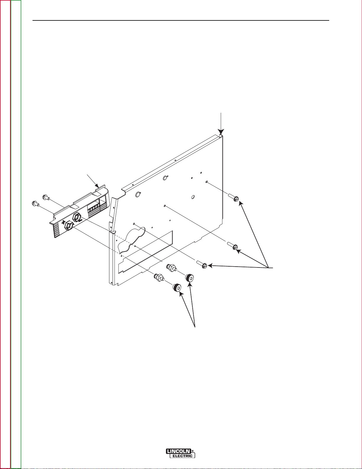
F-31 F-31
Center Panel Screws
Output Studs
Polarity Panel
Center
Panel
TROUBLESHOOTING & REPAIR
POWER MODULE REMOVAL AND REPLACEMENT PROCEDURE
(CONTINUED)
FIGURE F.9 – CENTER PANEL SCREW REMOVAL
Return to Section TOC Return to Section TOC Return to Section TOC Return to Section TOC
Return to Master TOC Return to Master TOC Return to Master TOC Return to Master TOC
COMPACT WIRE WELDERS
Page 86

F-32 F-32
NOTES
Return to Section TOC Return to Section TOC Return to Section TOC Return to Section TOC
Return to Master TOC Return to Master TOC Return to Master TOC Return to Master TOC
COMPACT WIRE WELDERS
Page 87

F-33 F-33
TROUBLESHOOTING & REPAIR
RECTIFIER, TRANSFORMER, CHOKE ASSEMBLY & CAPACITOR
REMOVAL AND REPLACEMENT PROCEDURE
WARNING
Service and repair should be performed by only Lincoln Electric factory trained personnel.
Unauthorized repairs performed on this equipment may result in danger to the technician
or machine operator and will invalidate your factory warranty. For your safety and to avoid
electrical shock, please observe all safety notes and precautions detailed throughout this
manual.
If for any reason you do not understand the test procedures or are unable to perform the
test/repairs safely, contact the Lincoln Electric Service Department for electrical troubleshooting assistance before you proceed. Call 1-888-935-3877.
WARNING
The liquid electrode in the capacitors is toxic. Do not touch the capacitors with any
part of your body.
TEST DESCRIPTION
This procedure will aid the technician in the removal and replacement of the components
in the Power Module Assembly.
MATERIALS NEEDED
Misc. Hand Tools
Dow Corning 340
Fine Steel Wool
Return to Section TOC Return to Section TOC Return to Section TOC Return to Section TOC
Return to Master TOC Return to Master TOC Return to Master TOC Return to Master TOC
COMPACT WIRE WELDERS
Page 88

Locking Tabs
3/8” Bolted Lead
(opposite side not shown)
F-34 F-34
TROUBLESHOOTING & REPAIR
RECTIFIER, TRANSFORMER, CHOKE ASSEMBLY & CAPACITOR
REMOVAL AND REPLACEMENT PROCEDURE (CONTINUED)
FIGURE F.10 – LOCKING TABS
1. Remove the input power to the machine.
2. Perform the Case Cover Removal Procedure.
3. Perform the Power Module Removal Procedure.
------------------------------------------------------------------------
4. With the Power Module removed from the machine,
depress locking tabs and remove the top chassis of
the module. See Figure F.10.
Return to Master TOC Return to Master TOC Return to Master TOC Return to Master TOC
Return to Section TOC Return to Section TOC Return to Section TOC Return to Section TOC
WARNING
ELECTRIC SHOCK can kill.
•
Have a n electrician install a n d
service this equipment. Turn the
input power OFF at the fuse box
before working on equipment. Do
not t ouch elect rically ho t parts.
COMPACT WIRE WELDERS
5. Using a 3/8” nutdriver, remove the two bolted leads
from the sides of the Rectifier. See Figure F.10.
6. Label and disconnect any associated leads.
7. Remove Rectifier and Capacitor from the machine.
See Figure F.12.
Page 89

F-35 F-35
TROUBLESHOOTING & REPAIR
RECTIFIER, TRANSFORMER, CHOKE ASSEMBLY & CAPACITOR
REMOVAL AND REPLACEMENT PROCEDURE (CONTINUED)
FIGURE F.11 – DOW CORNING 340
Return to Section TOC Return to Section TOC Return to Section TOC Return to Section TOC
8. When re-installing the capacitor, make sure that the
polarity is NOT reversed. See Figure F.12.
9. Clean the terminal surface of the capacitor with fine
steel wool and apply a thin coating of Dow Corning
340. See Figure F.12.
10. On the rectifier, clean the terminal surface with fine
steel wool and apply a thin coating of Dow Corning
340 on the Rectifier and re-install. See Figure F.11.
Return to Master TOC Return to Master TOC Return to Master TOC Return to Master TOC
COMPACT WIRE WELDERS
Page 90

Locking Tab
Inserts
Nut
Lock W asher
Plain W asher
Dow Corning 340
(apply to contact surfaces on both term inals)
F-36 F-36
TROUBLESHOOTING & REPAIR
RECTIFIER, TRANSFORMER, CHOKE ASSEMBLY & CAPACITOR
REMOVAL AND REPLACEMENT PROCEDURE (CONTINUED)
FIGURE F.12 – DOW CORNING APPLICATION AREAS
TRANSFORMER AND CHOKE
11. With the Power Module removed from the
machine, remove the top chassis on the
Module.
12. Remove the two bolted leads from the sides of
the rectifier using a 3/8” nutdriver.
Note: This step may already be complete.
14. Remove the Transformer. See Figure F.13.
15. When re-installing the Transformer, clean the
terminal surface and apply Dow Corning 340 to
the rectifier assembly leads. See Figure F.11.
Return to Section TOC Return to Section TOC Return to Section TOC Return to Section TOC
13. Label and disconnect any additional necessary
leads.
Return to Master TOC Return to Master TOC Return to Master TOC Return to Master TOC
COMPACT WIRE WELDERS
Page 91
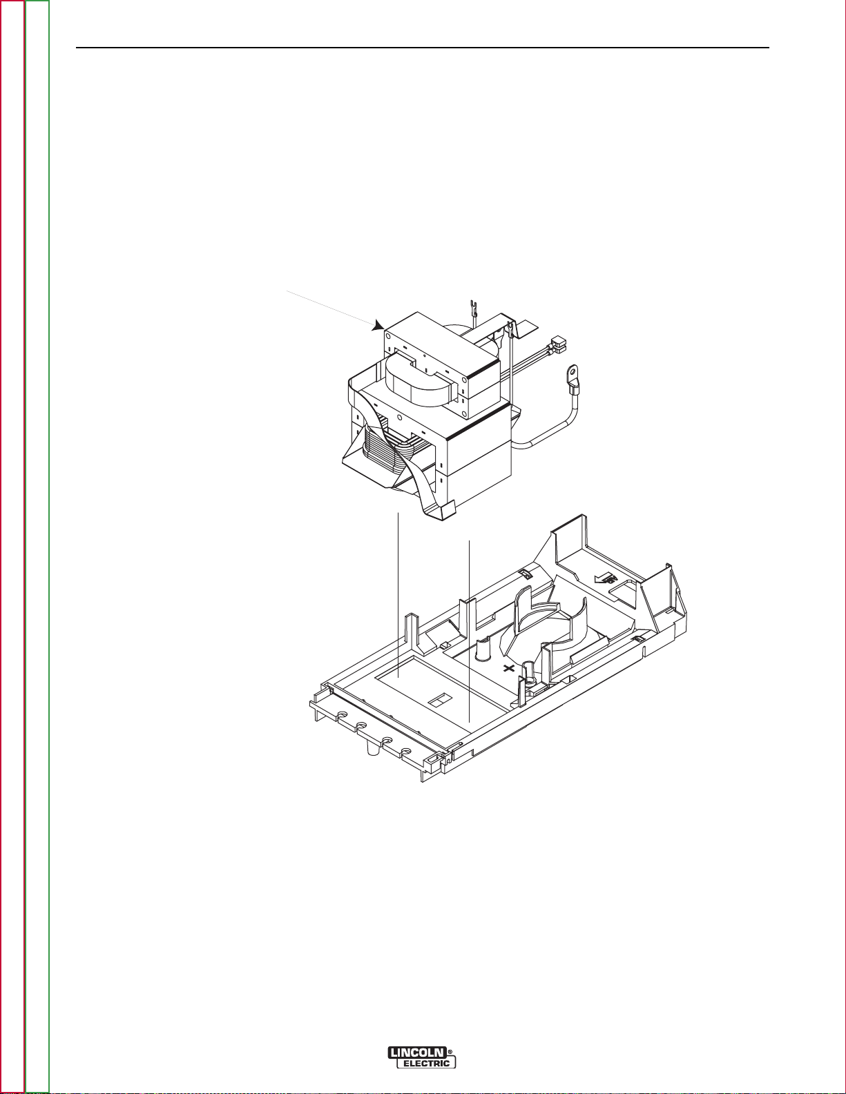
Transformer
F-37 F-37
TROUBLESHOOTING & REPAIR
RECTIFIER, TRANSFORMER, CHOKE ASSEMBLY & CAPACITOR
REMOVAL AND REPLACEMENT PROCEDURE (CONTINUED)
FIGURE F.13 – DOOR REMOVAL
Return to Section TOC Return to Section TOC Return to Section TOC Return to Section TOC
Return to Master TOC Return to Master TOC Return to Master TOC Return to Master TOC
COMPACT WIRE WELDERS
Page 92

F-38 F-38
NOTES
Return to Section TOC Return to Section TOC Return to Section TOC Return to Section TOC
Return to Master TOC Return to Master TOC Return to Master TOC Return to Master TOC
COMPACT WIRE WELDERS
Page 93

F-39 F-39
TROUBLESHOOTING & REPAIR
WIRE DRIVE MOTOR REMOVAL AND REPLACEMENT PROCEDURE
WARNING
Service and repair should be performed by only Lincoln Electric factory trained personnel.
Unauthorized repairs performed on this equipment may result in danger to the technician
or machine operator and will invalidate your factory warranty. For your safety and to avoid
electrical shock, please observe all safety notes and precautions detailed throughout this
manual.
If for any reason you do not understand the test procedures or are unable to perform the
test/repairs safely, contact the Lincoln Electric Service Department for electrical troubleshooting assistance before you proceed. Call 1-888-935-3877.
TEST DESCRIPTION
This procedure will aid the technician in the removal and replacement of the Wire Drive
Motor.
MATERIALS NEEDED
Misc. Hand Tools
Return to Section TOC Return to Section TOC Return to Section TOC Return to Section TOC
Return to Master TOC Return to Master TOC Return to Master TOC Return to Master TOC
COMPACT WIRE WELDERS
Page 94
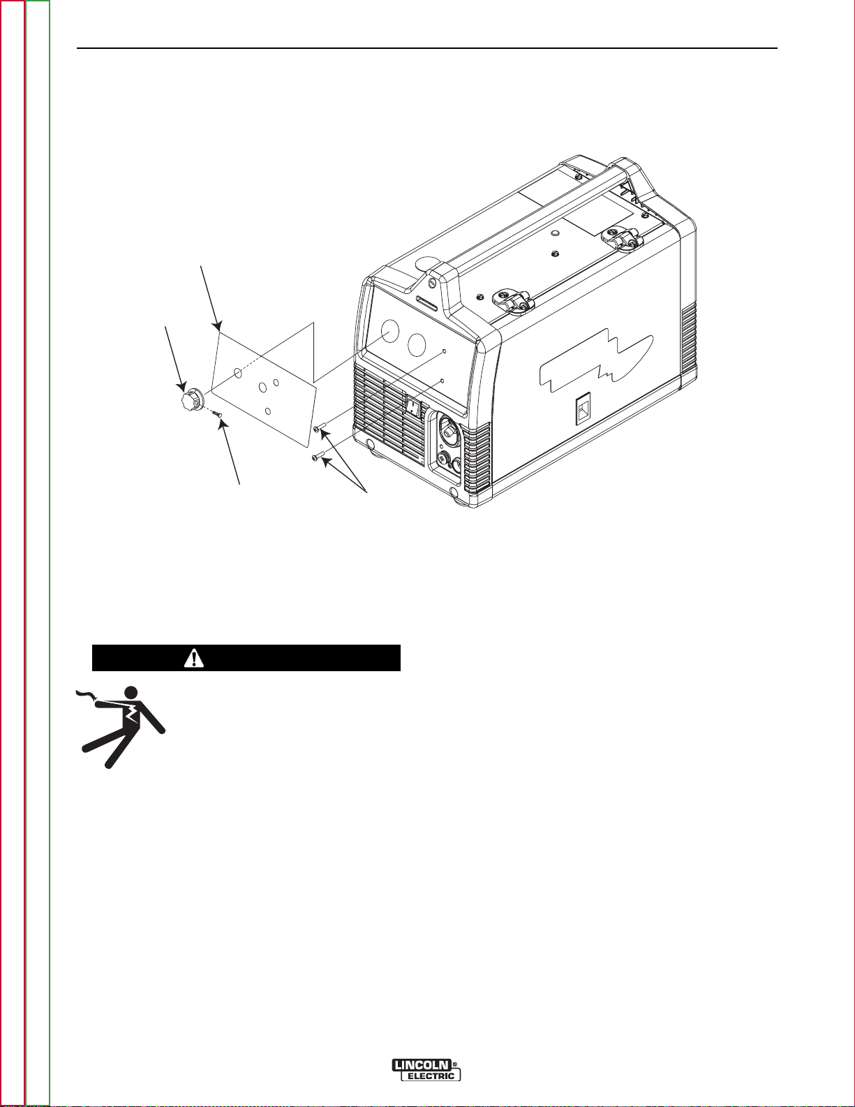
LINCOLN
ELECTRIC
Control Knob
Nameplate
Phillips
Screws
5/64” Allen
Set Screw
F-40 F-40
TROUBLESHOOTING & REPAIR
WIRE DRIVE MOTOR REMOVAL AND REPLACEMENT PROCEDURE
(CONTINUED)
FIGURE F.14 – CASEFRONT KNOB REMOVAL
1. Remove the input power to the machine.
2. Perform the Case Cover Removal Procedure.
WARNING
ELECTRIC SHOCK can kill.
•
Have a n electrician install a n d
service this equipment. Turn the
input power OFF at the fuse box
before working on equipment. Do
------------------------------------------------------------------------
3. Remove the two phillips screws from the gun trigger
receptacle.
4. Remove the two set screws from the voltage and
wire speed knobs using a 5/64” allen key. Remove
the two nuts and washers using a 1/2” Nutdriver.
See Figure F.14.
not t ouch elect rically ho t parts.
5. Remove the two phillips head screws from the
nameplate of the machine. See Figure F.14.
6. Gently pull the case front forward about an inch to
gain access.
7. Disconnect the air line from the wire drive motor.
Pliers may be necessary.
8. Label and disconnect any necessary leads. The
number of leads may vary depending upon the
machine’s model number.
9. Remove the three phillips mounting screws from the
right side of the machine. See Figure F.15.
10. Remove the Wire Drive Motor and replace.
Return to Section TOC Return to Section TOC Return to Section TOC Return to Section TOC
Return to Master TOC Return to Master TOC Return to Master TOC Return to Master TOC
COMPACT WIRE WELDERS
Page 95

3 Phillips
Mounting Screws
F-41 F-41
TROUBLESHOOTING & REPAIR
WIRE DRIVE MOTOR REMOVAL AND REPLACEMENT PROCEDURE
(CONTINUED)
FIGURE F.15 – WIRE DRIVE MOTOR
Return to Section TOC Return to Section TOC Return to Section TOC Return to Section TOC
Return to Master TOC Return to Master TOC Return to Master TOC Return to Master TOC
COMPACT WIRE WELDERS
Page 96

F-42 F-42
NOTES
Return to Section TOC Return to Section TOC Return to Section TOC Return to Section TOC
Return to Master TOC Return to Master TOC Return to Master TOC Return to Master TOC
COMPACT WIRE WELDERS
Page 97

F-43 F-43
TROUBLESHOOTING & REPAIR
FAN MOTOR ASSEMBLY REMOVAL AND REPLACEMENT PROCEDURE
WARNING
Service and repair should be performed by only Lincoln Electric factory trained personnel.
Unauthorized repairs performed on this equipment may result in danger to the technician
or machine operator and will invalidate your factory warranty. For your safety and to avoid
electrical shock, please observe all safety notes and precautions detailed throughout this
manual.
If for any reason you do not understand the test procedures or are unable to perform the
test/repairs safely, contact the Lincoln Electric Service Department for electrical troubleshooting assistance before you proceed. Call 1-888-935-3877.
TEST DESCRIPTION
This procedure will aid the technician in the removal and replacement of the Fan Motor
Assembly.
MATERIALS NEEDED
5/16” Nut Driver
5/64” Allen Key
1/2” Nut Driver
Phillips Screwdriver
Flathead Screwdriver
Pliers
Return to Section TOC Return to Section TOC Return to Section TOC Return to Section TOC
Return to Master TOC Return to Master TOC Return to Master TOC Return to Master TOC
COMPACT WIRE WELDERS
Page 98

2 Phillips
Screws
4 Phillips Screws
(only found on 140c/180c models)
Phillips Handle Mount Screw
(only found on 140c/180c models)
VIEWED FROM REAR OF MACHINE
F-44 F-44
TROUBLESHOOTING & REPAIR
FAN MOTOR ASSEMBLY REMOVAL AND REPLACEMENT PROCEDURE
(CONTINUED)
FIGURE F.16 – CENTER PANEL/FAN MOUNTING SCREW LOCATION
1. Remove the input power to the machine.
2. Perform the Case Cover Removal Procedure.
WARNING
ELECTRIC SHOCK can kill.
•
------------------------------------------------------------------------
3. Perform the Control Board Removal Procedure.
4. Using a flathead screwdriver, remove the center
panel mounting screws and the fan mounting
screws (depending upon model) located on the
back of the machine. See Figure F.16.
5. Depress any necessary locking tabs on rear of
machine.
Have a n electrician install a n d
service this equipment. Turn the
input power OFF at the fuse box
before working on equipment. Do
not touc h ele ctrica lly hot p arts.
Return to Master TOC Return to Master TOC Return to Master TOC Return to Master TOC
Return to Section TOC Return to Section TOC Return to Section TOC Return to Section TOC
COMPACT WIRE WELDERS
Page 99

Center Panel Screws
Center
Panel
F-45 F-45
TROUBLESHOOTING & REPAIR
FAN MOTOR ASSEMBLY REMOVAL AND REPLACEMENT PROCEDURE
(CONTINUED)
FIGURE F.17 – CENTER PANEL MOUNTING SCREWS
6. Remove the appropriate wiring and gas hose
from the top of the Power Module Chassis.
Pliers may be necessary.
7. Remove the flathead mounting screws from the
center panel. See Figure F.17.
Return to Section TOC Return to Section TOC Return to Section TOC Return to Section TOC
Return to Master TOC Return to Master TOC Return to Master TOC Return to Master TOC
COMPACT WIRE WELDERS
Page 100
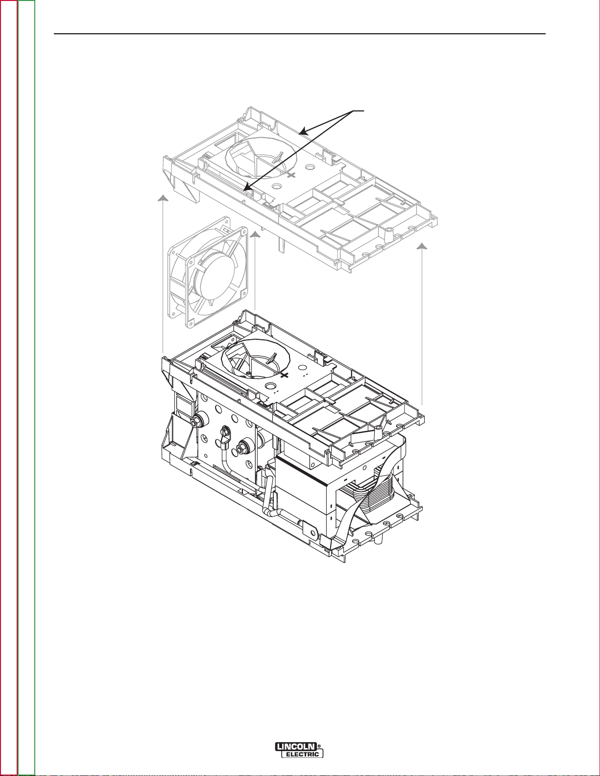
Locking Tabs
Fan
F-46 F-46
TROUBLESHOOTING & REPAIR
FAN MOTOR ASSEMBLY REMOVAL AND REPLACEMENT PROCEDURE
(CONTINUED)
FIGURE F.18 – LOCKING TABS & FAN
8. Depress the locking tabs and remove the top
Power Module Chassis. See Figure F.18.
9. Label and disconnect any necessary leads
attached to the Fan.
11. Upon installation of the new fan motor, make
sure that the rotation arrow is pointing up and
the flow arrow is pointing toward the front of the
machine.
Note: Fan should spin counter clockwise when
viewed from the rear of the machine.
Return to Section TOC Return to Section TOC Return to Section TOC Return to Section TOC
10. Remove the fan from the machine.
Return to Master TOC Return to Master TOC Return to Master TOC Return to Master TOC
COMPACT WIRE WELDERS
 Loading...