

Page 1
For use with machine code numbers: 10995,10996,11180,11181
RETURN TO MAIN MENU
Safety Depends on You
Lincoln arc welding and cutting
equipment is designed and built
with safety in mind. However,
your overall safety can be
increased by proper installation
. . . and thoughtful operation on
your part. DO NOT INSTALL,
OPERATE OR REPAIR THIS
EQUIPMENT WITHOUT READING THIS MANUAL AND THE
SAFETY PRECAUTIONS CONTAINED THROUGHOUT. And,
most importantly, think before you
act and be careful.
SVM178-B
April, 2011
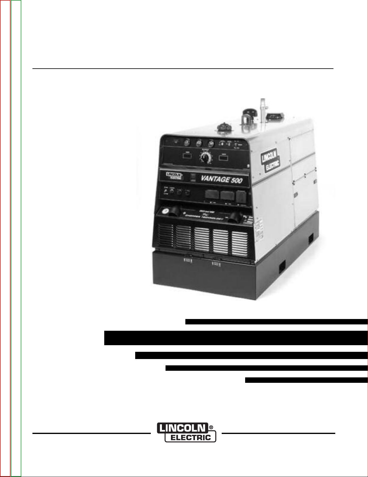
VANTAGE®500
11415,11416,11468
View Safety Info View Safety Info View Safety Info View Safety Info
Return to Master TOC Return to Master TOC Return to Master TOC Return to Master TOC
Cleveland, Ohio 44117-1199 U.S.A. TEL: 216.481.8100 FAX: 216.486.1751 WEB SITE: www.lincolnelectric.com
SERVICE MANUAL
Copyright © Lincoln Global Inc.
• World's Leader in Welding and Cutting Products •
• Sales and Service through Subsidiaries and Distributors Worldwide •
Page 2
i i
SAFETY
WARNING
CALIFORNIA PROPOSITION 65 WARNINGS
Diesel engine exhaust and some of its constituents
are known to the State of California to cause cancer, birth defects, and other reproductive harm.
The Above For Diesel Engines
ARC WELDING can be hazardous. PROTECT YOURSELF AND OTHERS FROM POSSIBLE SERIOUS INJURY OR DEATH.
KEEP CHILDREN AWAY. PACEMAKER WEARERS SHOULD CONSULT WITH THEIR DOCTOR BEFORE OPERATING.
Read and understand the following safety highlights. For additional safety information, it is strongly recommended that you
purchase a copy of “Safety in Welding & Cutting - ANSI Standard Z49.1” from the American Welding Society, P.O. Box 351040,
Miami, Florida 33135 or CSA Standard W117.2-1974. A Free copy of “Arc Welding Safety” booklet E205 is available from the
Lincoln Electric Company, 22801 St. Clair Avenue, Cleveland, Ohio 44117-1199.
BE SURE THAT ALL INSTALLATION, OPERATION, MAINTENANCE AND REPAIR PROCEDURES ARE
PERFORMED ONLY BY QUALIFIED INDIVIDUALS.
The engine exhaust from this product contains
chemicals known to the State of California to cause
cancer, birth defects, or other reproductive harm.
The Above For Gasoline Engines
FOR ENGINE
powered equipment.
1.a. Turn the engine off before troubleshooting and maintenance
work unless the maintenance work requires it to be running.
____________________________________________________
1.b.Operate engines in open, well-ventilated
areas or vent the engine exhaust fumes
outdoors.
____________________________________________________
1.c. Do not add the fuel near an open flame welding arc or when the engine is running. Stop
the engine and allow it to cool before refueling to prevent spilled fuel from vaporizing on
contact with hot engine parts and igniting. Do
not spill fuel when filling tank. If fuel is spilled,
wipe it up and do not start engine until fumes
have been eliminated.
____________________________________________________
1.d. Keep all equipment safety guards, covers and devices in position and in good repair.Keep hands, hair, clothing and tools
away from V-belts, gears, fans and all other moving parts
when starting, operating or repairing equipment.
____________________________________________________
1.e. In some cases it may be necessary to remove safety
guards to perform required maintenance. Remove
guards only when necessary and replace them when the
maintenance requiring their removal is complete.
Always use the greatest care when working near moving
parts.
___________________________________________________
1.h. To avoid scalding, do not remove the
radiator pressure cap when the engine is
hot.
ELECTRIC AND
MAGNETIC FIELDS
may be dangerous
2.a. Electric current flowing through any conductor causes
localized Electric and Magnetic Fields (EMF). Welding
current creates EMF fields around welding cables and
welding machines
2.b. EMF fields may interfere with some pacemakers, and
welders having a pacemaker should consult their physician
before welding.
2.c. Exposure to EMF fields in welding may have other health
effects which are now not known.
2.d. All welders should use the following procedures in order to
minimize exposure to EMF fields from the welding circuit:
2.d.1.
Route the electrode and work cables together - Secure
them with tape when possible.
2.d.2. Never coil the electrode lead around your body.
1.f. Do not put your hands near the engine fan.
Do not attempt to override the governor or
idler by pushing on the throttle control rods
while the engine is running.
___________________________________________________
1.g. To prevent accidentally starting gasoline engines while
turning the engine or welding generator during maintenance
work, disconnect the spark plug wires, distributor cap or
magneto wire as appropriate.
Return to Master TOC Return to Master TOC Return to Master TOC Return to Master TOC
2.d.3. Do not place your body between the electrode and
work cables. If the electrode cable is on your right
side, the work cable should also be on your right side.
2.d.4. Connect the work cable to the workpiece as close as
possible to the area being welded.
2.d.5. Do not work next to welding power source.
VANTAGE® 500
Page 3
ii ii
SAFETY
ELECTRIC SHOCK can kill.
3.a. The electrode and work (or ground) circuits
are electrically “hot” when the welder is on.
Do not touch these “hot” parts with your bare
skin or wet clothing. Wear dry, hole-free
gloves to insulate hands.
3.b. Insulate yourself from work and ground using dry insulation.
Make certain the insulation is large enough to cover your full
area of physical contact with work and ground.
In addition to the normal safety precautions, if welding
must be performed under electrically hazardous
conditions (in damp locations or while wearing wet
clothing; on metal structures such as floors, gratings or
scaffolds; when in cramped positions such as sitting,
kneeling or lying, if there is a high risk of unavoidable or
accidental contact with the workpiece or ground) use
the following equipment:
• Semiautomatic DC Constant Voltage (Wire) Welder.
• DC Manual (Stick) Welder.
• AC Welder with Reduced Voltage Control.
3.c. In semiautomatic or automatic wire welding, the electrode,
electrode reel, welding head, nozzle or semiautomatic
welding gun are also electrically “hot”.
3.d. Always be sure the work cable makes a good electrical
connection with the metal being welded. The connection
should be as close as possible to the area being welded.
3.e. Ground the work or metal to be welded to a good electrical
(earth) ground.
3.f.
Maintain the electrode holder, work clamp, welding cable and
welding machine in good, safe operating condition. Replace
damaged insulation.
3.g. Never dip the electrode in water for cooling.
3.h. Never simultaneously touch electrically “hot” parts of
electrode holders connected to two welders because voltage
between the two can be the total of the open circuit voltage
of both welders.
3.i. When working above floor level, use a safety belt to protect
yourself from a fall should you get a shock.
3.j. Also see Items 6.c. and 8.
ARC RAYS can burn.
4.a. Use a shield with the proper filter and cover
plates to protect your eyes from sparks and
the rays of the arc when welding or observing
open arc welding. Headshield and filter lens
should conform to ANSI Z87. I standards.
4.b. Use suitable clothing made from durable flame-resistant
material to protect your skin and that of your helpers from
the arc rays.
4.c. Protect other nearby personnel with suitable, non-flammable
screening and/or warn them not to watch the arc nor expose
themselves to the arc rays or to hot spatter or metal.
FUMES AND GASES
can be dangerous.
5.a. Welding may produce fumes and gases
hazardous to health. Avoid breathing these
fumes and gases.When welding, keep
your head out of the fume. Use enough
ventilation and/or exhaust at the arc to keep
fumes and gases away from the breathing zone. When
welding with electrodes which require special
ventilation such as stainless or hard facing (see
instructions on container or MSDS) or on lead or
cadmium plated steel and other metals or coatings
which produce highly toxic fumes, keep exposure as
low as possible and within applicable OSHA PEL and
ACGIH TLV limits using local exhaust or mechanical ventilation. In confined spaces or in some circumstances,
outdoors, a respirator may be required. Additional precautions are also required when welding on galvanized
steel.
5. b. The operation of welding fume control equipment is affected
by various factors including proper use and positioning of the
equipment, maintenance of the equipment and the specific
welding procedure and application involved. Worker exposure level should be checked upon installation and periodically thereafter to be certain it is within applicable OSHA PEL
and ACGIH TLV limits.
5.c.
Do not weld in locations near chlorinated hydrocarbon
coming from degreasing, cleaning or spraying operations.
The heat and rays of the arc can react with solvent vapors
form phosgene, a highly toxic gas, and other irritating products.
vapors
to
Return to Master TOC Return to Master TOC Return to Master TOC Return to Master TOC
5.d. Shielding gases used for arc welding can displace air and
cause injury or death. Always use enough ventilation,
especially in confined areas, to insure breathing air is safe.
5.e. Read and understand the manufacturer’s instructions for this
equipment and the consumables to be used, including the
material safety data sheet (MSDS) and follow your
employer’s safety practices. MSDS forms are available from
your welding distributor or from the manufacturer.
5.f. Also see item 1.b.
VANTAGE® 500
Page 4
iii iii
SAFETY
WELDING and CUTTING
SPARKS can cause fire or
explosion.
6.a.
this is not possible, cover them to prevent the welding sparks
from starting a fire. Remember that welding sparks and hot
materials from welding can easily go through small cracks
and openings to adjcent areas. Avoid welding near hydraulic
lines. Have a fire extinguisher readily available.
6.b. Where compressed gases are to be used at the job site,
special precautions should be used to prevent hazardous
situations. Refer to “Safety in Welding and Cutting” (ANSI
Standard Z49.1) and the operating information for the
equipment being used.
6.c. When not welding, make certain no part of the electrode
circuit is touching the work or ground. Accidental contact can
cause overheating and create a fire hazard.
6.d. Do not heat, cut or weld tanks, drums or containers until the
proper steps have been taken to insure that such procedures
will not cause flammable or toxic vapors from substances
inside. They can cause an explosion even
been “cleaned”. For information, purchase “Recommended
Safe Practices for the
Containers and Piping That Have Held Hazardous
Substances”, AWS F4.1 from the American Welding Society
(see address above).
6.e. Vent hollow castings or containers before heating, cutting or
welding. They may explode.
Sparks and spatter are thrown from the welding arc. Wear oil
6.f.
free protective garments such as leather gloves, heavy shirt,
cuffless trousers, high shoes and a cap over your hair. Wear
ear plugs when welding out of position or in confined places.
Always wear safety glasses with side shields when in a
welding area.
6.g. Connect the work cable to the work as close to the welding
area as practical. Work cables connected to the building
framework or other locations away from the welding area
increase the possibility of the welding current passing through
lifting chains, crane cables or other alternate circuits. This can
create fire hazards or overheat lifting chains or cables until
they fail.
6.h. Also see item 1.c.
Remove fire hazards from the welding area.
though
they have
Preparation
for Welding and Cutting of
CYLINDER may explode
if damaged.
7.a. Use only compressed gas cylinders
If
pressure used. All hoses, fittings, etc. should be suitable for
the application and maintained in good condition.
7.b. Always keep cylinders in an upright position securely
chained to an undercarriage or fixed support.
7.c. Cylinders should be located:
• Away from areas where they may be struck or subjected to
physical damage.
• A safe distance from arc welding or cutting operations and
any other source of heat, sparks, or flame.
7.d. Never allow the electrode, electrode holder or any other
electrically “hot” parts to touch a cylinder.
7.e. Keep your head and face away from the cylinder valve outlet
when opening the cylinder valve.
7.f. Valve protection caps should always be in place and hand
tight except when the cylinder is in use or connected for
use.
7.g. Read and follow the instructions on compressed gas
cylinders, associated equipment, and CGA publication P-l,
“Precautions for Safe Handling of Compressed Gases in
Cylinders,” available from the Compressed Gas Association
1235 Jefferson Davis Highway, Arlington, VA 22202.
containing the correct shielding gas for the
process used and properly operating
regulators designed for the gas and
FOR ELECTRICALLY
powered equipment.
8.a. Turn off input power using the disconnect
switch at the fuse box before working on
the equipment.
8.b. Install equipment in accordance with the U.S. National
Electrical Code, all local codes and the manufacturer’s
recommendations.
8.c. Ground the equipment in accordance with the U.S. National
Electrical Code and the manufacturer’s recommendations.
6.I. Read and follow NFPA 51B “ Standard for Fire Prevention
During Welding, Cutting and Other Hot Work”, available from
NFPA, 1 Batterymarch Park,PO box 9101, Quincy, Ma
022690-9101.
6.j. Do not use a welding power source for pipe thawing.
Refer to http://www.lincolnelectric.com/safety for additional safety information.
Return to Master TOC Return to Master TOC Return to Master TOC Return to Master TOC
VANTAGE® 500
Page 5

iv iv
SAFETY
PRÉCAUTIONS DE SÛRETÉ
Pour votre propre protection lire et observer toutes les instructions
et les précautions de sûreté specifiques qui parraissent dans ce
manuel aussi bien que les précautions de sûreté générales suivantes:
Sûreté Pour Soudage A L’Arc
1. Protegez-vous contre la secousse électrique:
a. Les circuits à l’électrode et à la piéce sont sous tension
quand la machine à souder est en marche. Eviter toujours
tout contact entre les parties sous tension et la peau nue
ou les vétements mouillés. Porter des gants secs et sans
trous pour isoler les mains.
b. Faire trés attention de bien s’isoler de la masse quand on
soude dans des endroits humides, ou sur un plancher metallique ou des grilles metalliques, principalement dans
les positions assis ou couché pour lesquelles une grande
partie du corps peut être en contact avec la masse.
c. Maintenir le porte-électrode, la pince de masse, le câble de
soudage et la machine à souder en bon et sûr état defonctionnement.
d.Ne jamais plonger le porte-électrode dans l’eau pour le
refroidir.
e. Ne jamais toucher simultanément les parties sous tension
des porte-électrodes connectés à deux machines à souder
parce que la tension entre les deux pinces peut être le total
de la tension à vide des deux machines.
f. Si on utilise la machine à souder comme une source de
courant pour soudage semi-automatique, ces precautions
pour le porte-électrode s’applicuent aussi au pistolet de
soudage.
2. Dans le cas de travail au dessus du niveau du sol, se protéger
contre les chutes dans le cas ou on recoit un choc. Ne jamais
enrouler le câble-électrode autour de n’importe quelle partie du
corps.
3. Un coup d’arc peut être plus sévère qu’un coup de soliel, donc:
6. Eloigner les matériaux inflammables ou les recouvrir afin de
prévenir tout risque d’incendie dû aux étincelles.
7. Quand on ne soude pas, poser la pince à une endroit isolé de
la masse. Un court-circuit accidental peut provoquer un
échauffement et un risque d’incendie.
8. S’assurer que la masse est connectée le plus prés possible de
la zone de travail qu’il est pratique de le faire. Si on place la
masse sur la charpente de la construction ou d’autres endroits
éloignés de la zone de travail, on augmente le risque de voir
passer le courant de soudage par les chaines de levage,
câbles de grue, ou autres circuits. Cela peut provoquer des
risques d’incendie ou d’echauffement des chaines et des
câbles jusqu’à ce qu’ils se rompent.
9. Assurer une ventilation suffisante dans la zone de soudage.
Ceci est particuliérement important pour le soudage de tôles
galvanisées plombées, ou cadmiées ou tout autre métal qui
produit des fumeés toxiques.
10. Ne pas souder en présence de vapeurs de chlore provenant
d’opérations de dégraissage, nettoyage ou pistolage. La
chaleur ou les rayons de l’arc peuvent réagir avec les vapeurs
du solvant pour produire du phosgéne (gas fortement toxique)
ou autres produits irritants.
11. Pour obtenir de plus amples renseignements sur la sûreté, voir
le code “Code for safety in welding and cutting” CSA Standard
W 117.2-1974.
PRÉCAUTIONS DE SÛRETÉ POUR
LES MACHINES À SOUDER À
TRANSFORMATEUR ET À
REDRESSEUR
Return to Master TOC Return to Master TOC Return to Master TOC Return to Master TOC
a. Utiliser un bon masque avec un verre filtrant approprié ainsi
qu’un verre blanc afin de se protéger les yeux du rayonnement de l’arc et des projections quand on soude ou
quand on regarde l’arc.
b. Porter des vêtements convenables afin de protéger la peau
de soudeur et des aides contre le rayonnement de l‘arc.
c. Protéger l’autre personnel travaillant à proximité au
soudage à l’aide d’écrans appropriés et non-inflammables.
4. Des gouttes de laitier en fusion sont émises de l’arc de
soudage. Se protéger avec des vêtements de protection libres
de l’huile, tels que les gants en cuir, chemise épaisse, pantalons sans revers, et chaussures montantes.
5. Toujours porter des lunettes de sécurité dans la zone de
soudage. Utiliser des lunettes avec écrans lateraux dans les
zones où l’on pique le laitier.
VANTAGE® 500
1. Relier à la terre le chassis du poste conformement au code de
l’électricité et aux recommendations du fabricant. Le dispositif
de montage ou la piece à souder doit être branché à une
bonne mise à la terre.
2. Autant que possible, I’installation et l’entretien du poste seront
effectués par un électricien qualifié.
3. Avant de faires des travaux à l’interieur de poste, la debrancher à l’interrupteur à la boite de fusibles.
4. Garder tous les couvercles et dispositifs de sûreté à leur place.
Page 6

v v
SAFETY
Electromagnetic Compatibility (EMC)
Conformance
Products displaying the CE mark are in conformity with European Community Council Directive of 15 Dec
2004 on the approximation of the laws of the Member States relating to electromagnetic compatibility,
2004/108/EC. It was manufactured in conformity with a national standard that implements a harmonized
standard: EN 60974-10 Electromagnetic Compatibility (EMC) Product Standard for Arc Welding Equipment.
It is for use with other Lincoln Electric equipment. It is designed for industrial and professional use.
Introduction
All electrical equipment generates small amounts of electromagnetic emission. Electrical emission may be
transmitted through power lines or radiated through space, similar to a radio transmitter. When emissions
are received by other equipment, electrical interference may result. Electrical emissions may affect many
kinds of electrical equipment; other nearby welding equipment, radio and TV reception, numerical controlled
machines, telephone systems, computers, etc. Be aware that interference may result and extra precautions
may be required when a welding power source is used in a domestic establishment.
Installation and Use
The user is responsible for installing and using the welding equipment according to the manufacturer’s
instructions. If electromagnetic disturbances are detected then it shall be the responsibility of the user of the
welding equipment to resolve the situation with the technical assistance of the manufacturer. In some cases
this remedial action may be as simple as earthing (grounding) the welding circuit, see Note. In other cases
it could involve construction of an electromagnetic screen enclosing the power source and the work complete with associated input filters. In all cases electromagnetic disturbances must be reduced to the point
where they are no longer troublesome.
Note: The welding circuit may or may not be earthed for safety reasons according to national
codes. Changing the earthing arrangements should only be authorized by a person who is
competent to access whether the changes will increase the risk of injury, e.g., by allowing
parallel welding current return paths which may damage the earth circuits of other equipment.
Assessment of Area
Before installing welding equipment the user shall make an assessment of potential electromagnetic problems in the surrounding area. The following shall be taken into account:
a) other supply cables, control cables, signaling and telephone cables; above, below and adjacent to the
welding equipment;
b) radio and television transmitters and receivers;
c) computer and other control equipment;
d) safety critical equipment, e.g., guarding of industrial equipment;
e) the health of the people around, e.g., the use of pacemakers and hearing aids;
f) equipment used for calibration or measurement
g) the immunity of other equipment in the environment. The user shall ensure that other equipment being
used in the environment is compatible. This may require additional protection measures;
Return to Master TOC Return to Master TOC Return to Master TOC Return to Master TOC
h) the time of day that welding or other activities are to be carried out.
VANTAGE® 500
Page 7

vi vi
SAFETY
Electromagnetic Compatibility (EMC)
The size of the surrounding area to be considered will depend on the structure of the building and other
activities that are taking place. The surrounding area may extend beyond the boundaries of the premises.
Methods of Reducing Emissions
Mains Supply
Welding equipment should be connected to the mains supply according to the manufacturer’s recommendations. If interference occurs, it may be necessary to take additional precautions such as filtering of the mains
supply. Consideration should be given to shielding the supply cable of permanently installed welding equipment, in metallic conduit or equivalent. Shielding should be electrically continuous throughout its length. The
shielding should be connected to the welding power source so that good electrical contact is maintained
between the conduit and the welding power source enclosure.
Maintenance of the Welding Equipment
The welding equipment should be routinely maintained according to the manufacturer’s recommendations.
All access and service doors and covers should be closed and properly fastened when the welding equipment is in operation. The welding equipment should not be modified in any way except for those changes
and adjustments covered in the manufacturers instructions. In particular, the spark gaps of arc striking and
stabilizing devices should be adjusted and maintained according to the manufacturer’s recommendations.
Welding Cables
The welding cables should be kept as short as possible and should be positioned close together, running at
or close to floor level.
Equipotential Bonding
Bonding of all metallic components in the welding installation and adjacent to it should be considered.
However, metallic components bonded to the work piece will increase the risk that the operator could
receive a shock by touching these metallic components and the electrode at the same time. The operator
should be insulated from all such bonded metallic components.
Earthing of the Workpiece
Where the workpiece is not bonded to earth for electrical safety, not connected to earth because of its size
and position, e.g., ships hull or building steelwork, a connection bonding the workpiece to earth may reduce
emissions in some, but not all instances. Care should be taken to prevent the earthing of the workpiece
increasing the risk of injury to users, or damage to other electrical equipment. Where necessary, the connection of the workpiece to earth should be made by a direct connection to the workpiece, but in some
countries where direct connection is not permitted, the bonding should be achieved by suitable capacitance,
selected according to national regulations.
Screening and Shielding
Selective screening and shielding of other cables and equipment in the surrounding area may alleviate
problems of interference. Screening of the entire welding installation may be considered for special applica-
1
tions.
Return to Master TOC Return to Master TOC Return to Master TOC Return to Master TOC
_________________________
1
Portions of the preceding text are contained in EN 60974-10: “Electromagnetic Compatibility (EMC) product standard for arc welding equipment.”
VANTAGE® 500
Page 8

I I
RETURN TO MAIN MENU
- MASTER TABLE OF CONTENTS FOR ALL SECTIONS -
Page
Safety . . . . . . . . . . . . . . . . . . . . . . . . . . . . . . . . . . . . . . . . . . . . . . . . . . . . . . . . . . . . . . . . . . . . . . . . . . .i-iv
Installation . . . . . . . . . . . . . . . . . . . . . . . . . . . . . . . . . . . . . . . . . . . . . . . . . . . . . . . . . . . . . . . . . .Section A
VANTAGE® 500 Deutz F3L912 (Code 10995) . . . . . . . . . . . . . . . . . . . . . . . . . . . . . . . . . . . . . . . .A1
VANTAGE® 500 Deutz F4L2011 (Code 11180, 11415) . . . . . . . . . . . . . . . . . . . . . . . . . . . . . . . . . .A2
VANTAGE® 500 Deutz D2011L4i (Code 11468) . . . . . . . . . . . . . . . . . . . . . . . . . . . . . . . . . . . . . . .A3
VANTAGE® 500 Cummins B3.3 (Code 10996) . . . . . . . . . . . . . . . . . . . . . . . . . . . . . . . . . . . . . . .A4
VANTAGE® 500 Cummins B3.3 (Code 11181, 11416) . . . . . . . . . . . . . . . . . . . . . . . . . . . . . . . . . .A5
Operation . . . . . . . . . . . . . . . . . . . . . . . . . . . . . . . . . . . . . . . . . . . . . . . . . . . . . . . . . . . . . . . . . .Section B
VANTAGE® 500 Deutz F3L912 (Code 10995) . . . . . . . . . . . . . . . . . . . . . . . . . . . . . . . . . . . . . . . .B1
VANTAGE® 500 Deutz F4L2011 (Code 11180, 11415) . . . . . . . . . . . . . . . . . . . . . . . . . . . . . . . . . .B2
VANTAGE® 500 Deutz D2011L4i (Code 11468) . . . . . . . . . . . . . . . . . . . . . . . . . . . . . . . . . . . . . . .B3
VANTAGE® 500 Cummins B3.3 (Code 10996) . . . . . . . . . . . . . . . . . . . . . . . . . . . . . . . . . . . . . . .B4
VANTAGE® 500 Cummins B3.3 (Code 11181, 11416) . . . . . . . . . . . . . . . . . . . . . . . . . . . . . . . . . .B5
Accessories . . . . . . . . . . . . . . . . . . . . . . . . . . . . . . . . . . . . . . . . . . . . . . . . . . . . . . . . . . . . . . . .Section C
VANTAGE® 500 Deutz F3L912 (Code 10995) . . . . . . . . . . . . . . . . . . . . . . . . . . . . . . . . . . . . . . . .C1
VANTAGE® 500 Deutz F4L2011 (Code 11180, 11415) . . . . . . . . . . . . . . . . . . . . . . . . . . . . . . . . . .C2
VANTAGE® 500 Deutz D2011L4i (Code 11468) . . . . . . . . . . . . . . . . . . . . . . . . . . . . . . . . . . . . . . .C3
VANTAGE® 500 Cummins B3.3 (Code 10996) . . . . . . . . . . . . . . . . . . . . . . . . . . . . . . . . . . . . . . .C4
VANTAGE® 500 Cummins B3.3 (Code 11181, 11416) . . . . . . . . . . . . . . . . . . . . . . . . . . . . . . . . . .C5
Maintenance . . . . . . . . . . . . . . . . . . . . . . . . . . . . . . . . . . . . . . . . . . . . . . . . . . . . . . . . . . . . . . . .Section D
VANTAGE® 500 Deutz F3L912 (Code 10995) . . . . . . . . . . . . . . . . . . . . . . . . . . . . . . . . . . . . . . . .D1
VANTAGE® 500 Deutz F4L2011 (Code 11180, 11415) . . . . . . . . . . . . . . . . . . . . . . . . . . . . . . . . . .D2
VANTAGE® 500 Deutz D2011L4i (Code 11468) . . . . . . . . . . . . . . . . . . . . . . . . . . . . . . . . . . . . . . .D3
VANTAGE® 500 Cummins B3.3 (Code 10996) . . . . . . . . . . . . . . . . . . . . . . . . . . . . . . . . . . . . . . .D4
VANTAGE® 500 Cummins B3.3 (Code 11181, 11416) . . . . . . . . . . . . . . . . . . . . . . . . . . . . . . . . . .D5
Theory of Operation . . . . . . . . . . . . . . . . . . . . . . . . . . . . . . . . . . . . . . . . . . . . . . . . . . . . . . . . . .Section E
Troubleshooting and Repair . . . . . . . . . . . . . . . . . . . . . . . . . . . . . . . . . . . . . . . . . . . . . . . . . . .Section F
Electrical Diagrams . . . . . . . . . . . . . . . . . . . . . . . . . . . . . . . . . . . . . . . . . . . . . . . . . . . . . . . . . .Section G
Parts Lists . . . . . . . . . . . . . . . . . . . . . . . . . . . . . . . . . . . . . . . . . . . . . . . . . . . . . . . . . . . . . . .P-472, P-508
VANTAGE® 500 Deutz F3L912 (Code 10995) . . . . . . . . . . . . . . . . . . . . . . . . . . . . . . . . . . . . . .P-472
VANTAGE® 500 Deutz F4L2011 (Code 11180, 11415) . . . . . . . . . . . . . . . . . . . . . . . . . . . . . . .P-508
VANTAGE® 500 Deutz D2011L4i (Code 11468) . . . . . . . . . . . . . . . . . . . . . . . . . . . . . . . . . . . .P-508
VANTAGE® 500 Cummins B3.3 (Code 10996) . . . . . . . . . . . . . . . . . . . . . . . . . . . . . . . . . . . . .P-472
VANTAGE® 500 Cummins B3.3 (Code 11181, 11416) . . . . . . . . . . . . . . . . . . . . . . . . . . . . . . .P-508
VANTAGE® 500
Page 9

A1.1 A1.1
TABLE OF CONTENTS - INSTALLATION SECTION
Installation - VANTAGE® 500 Deutz F3L912 (Code 10995)
Technical Specifications . . . . . . . . . . . . . . . . . . . . . . . . . . . . . . . . . . . . . . . . . . . . . . . . . . . . . . . . . . . . . . .A1.2
Safety Precautions . . . . . . . . . . . . . . . . . . . . . . . . . . . . . . . . . . . . . . . . . . . . . . . . . . . . . . . . . . . . . . . . . . .A1.3
Location/Ventilation . . . . . . . . . . . . . . . . . . . . . . . . . . . . . . . . . . . . . . . . . . . . . . . . . . . . . . . . . . . . . . . . . .A1.3
Storing . . . . . . . . . . . . . . . . . . . . . . . . . . . . . . . . . . . . . . . . . . . . . . . . . . . . . . . . . . . . . . . . . . . . . . . . .A1.3
Stacking . . . . . . . . . . . . . . . . . . . . . . . . . . . . . . . . . . . . . . . . . . . . . . . . . . . . . . . . . . . . . . . . . . . . . . . .A1.3
Angle of Operation . . . . . . . . . . . . . . . . . . . . . . . . . . . . . . . . . . . . . . . . . . . . . . . . . . . . . . . . . . . . . . . .A1.3
Lifting . . . . . . . . . . . . . . . . . . . . . . . . . . . . . . . . . . . . . . . . . . . . . . . . . . . . . . . . . . . . . . . . . . . . . . . . . .A1.4
High Altitude Operation . . . . . . . . . . . . . . . . . . . . . . . . . . . . . . . . . . . . . . . . . . . . . . . . . . . . . . . . . . . .A1.4
High Temperature Operation . . . . . . . . . . . . . . . . . . . . . . . . . . . . . . . . . . . . . . . . . . . . . . . . . . . . . . . .A1.4
Towing . . . . . . . . . . . . . . . . . . . . . . . . . . . . . . . . . . . . . . . . . . . . . . . . . . . . . . . . . . . . . . . . . . . . . . . . .A1.4
Vehicle Mounting . . . . . . . . . . . . . . . . . . . . . . . . . . . . . . . . . . . . . . . . . . . . . . . . . . . . . . . . . . . . . . . . .A1.4
Pre-Operation Engine Service . . . . . . . . . . . . . . . . . . . . . . . . . . . . . . . . . . . . . . . . . . . . . . . . . . . . . . . . . .A1.5
Oil . . . . . . . . . . . . . . . . . . . . . . . . . . . . . . . . . . . . . . . . . . . . . . . . . . . . . . . . . . . . . . . . . . . . . . . . . . . . .A1.5
Fuel . . . . . . . . . . . . . . . . . . . . . . . . . . . . . . . . . . . . . . . . . . . . . . . . . . . . . . . . . . . . . . . . . . . . . . . . . . .A1.5
Fuel Cap . . . . . . . . . . . . . . . . . . . . . . . . . . . . . . . . . . . . . . . . . . . . . . . . . . . . . . . . . . . . . . . . . . . . . . .A1.5
Engine Cooling System . . . . . . . . . . . . . . . . . . . . . . . . . . . . . . . . . . . . . . . . . . . . . . . . . . . . . . . . . . . .A1.5
Battery Connection . . . . . . . . . . . . . . . . . . . . . . . . . . . . . . . . . . . . . . . . . . . . . . . . . . . . . . . . . . . . . . .A1.5
Muffler Outlet Pipe . . . . . . . . . . . . . . . . . . . . . . . . . . . . . . . . . . . . . . . . . . . . . . . . . . . . . . . . . . . . . . . .A1.6
Spark Arrester . . . . . . . . . . . . . . . . . . . . . . . . . . . . . . . . . . . . . . . . . . . . . . . . . . . . . . . . . . . . . . . . . . .A1.6
High Frequency Generators for TIG Applications . . . . . . . . . . . . . . . . . . . . . . . . . . . . . . . . . . . . . . . . . . .A1.6
Electrical Connections . . . . . . . . . . . . . . . . . . . . . . . . . . . . . . . . . . . . . . . . . . . . . . . . . . . . . . . . . . . . . . . .A1.6
Remote Control . . . . . . . . . . . . . . . . . . . . . . . . . . . . . . . . . . . . . . . . . . . . . . . . . . . . . . . . . . . . . . . . . .A1.6
Welding Terminals . . . . . . . . . . . . . . . . . . . . . . . . . . . . . . . . . . . . . . . . . . . . . . . . . . . . . . . . . . . . . . . .A1.6
Return to Master TOC Return to Master TOC Return to Master TOC Return to Master TOC
Welding Output Cables . . . . . . . . . . . . . . . . . . . . . . . . . . . . . . . . . . . . . . . . . . . . . . . . . . . . . . . . . . . .A1.7
Machine Grounding . . . . . . . . . . . . . . . . . . . . . . . . . . . . . . . . . . . . . . . . . . . . . . . . . . . . . . . . . . . . . . .A1.7
Auxiliary Power Receptacles . . . . . . . . . . . . . . . . . . . . . . . . . . . . . . . . . . . . . . . . . . . . . . . . . . . . . . . .A1.7
Standby Power Connections . . . . . . . . . . . . . . . . . . . . . . . . . . . . . . . . . . . . . . . . . . . . . . . . . . . . . . . .A1.7
VANTAGE® 500
Page 10
A1.2 A1.2
INSTALLATION
TECHNICAL SPECIFICATIONS - Vantage 500® DEUTZ (K2271-1)
INPUT - DIESEL ENGINE
Make /Model Description Speed (RPM) Displacement Starting Capacities
System
Deutz 3 cylinder High Idle 1900 173 cu. in 12VDC battery Fuel
F3L 912 44HP (33 kw) (2.83L) & Starter (25 US gal
Diesel Engine @ 1800 RPM Full Load 1800 94.6L)
Code 10995 Bore x Stroke Oil:
9.5 QTS.
3.94” x 4.72” 9.0L
(100mm x 120mm)
RATED OUTPUT @ 104°F(40°C) - WELDER
Duty Cycle Welding Output Volts at Rated Amps
100% 500 Amps (DC multi-purpose) 40 Volts
60% 550 Amps (DC multi-purpose) 36 volts
50% 575 Amps (DC multi-purpose) 35 volts
OUTPUT @ 104°F(40°C) - WELDER AND GENERATOR
Welding Range
30 - 575 Amps CC/CV
20 - 250 Amps TIG
Open Circuit Voltage
60 Max OCV @ 1900 RPM
Auxiliary Power
120/240 VAC
12,000 WATTS, 60 Hz.
(1)
PHYSICAL DIMENSIONS
Height
(2)
Width Depth Weight
Return to Section TOC Return to Section TOC Return to Section TOC Return to Section TOC
42.0 in 31.5 in. 63.1 in. 1615 lbs.
(1066.8 mm) (800.1mm) (1603mm) (733kg)
(Approx)
1. Output rating in watts is equivalent to volt-amperes at unity power factor.
Output voltage is within +/- 10% at all loads up to rated capacity. When welding, available auxiliary power will be reduced.
2. Top of Enclosure. Add 6.6” (167.6mm) for exhaust.
Return to Master TOC Return to Master TOC Return to Master TOC Return to Master TOC
VANTAGE® 500
Page 11

A1.3 A1.3
INSTALLATION
Read this entire installation section before you
start installation.
SAFETY PRECAUTIONS
WARNING
Do not attempt to use this equipment until you
have thoroughly read all operating and maintenance manuals supplied with your machine. They
include important safety precautions, detailed
engine starting, operating and maintenance
instructions and parts lists.
ELECTRIC SHOCK can kill.
• Do not touch electrically live parts
such as output terminals or internal
wiring.
• Insulate yourself from the work and
ground.
• Always wear dry insulating gloves.
ENGINE EXHAUST can kill.
• Use in open, well ventilated areas or
vent exhaust outside
• Do not stack anything near the
engine.
LOCATION / VENTILATION
The welder should be located to provide an unrestricted flow of clean, cool air to the cooling air inlets and to
avoid restricting the cooling air outlets. Also, locate the
welder so that the engine exhaust fumes are properly
vented to an outside area.
CAUTION
DO NOT MOUNT OVER COMBUSTIBLE
SURFACES
Where there is a combustible surface directly
under stationary or fixed electrical equipment, that
surface should be covered with a steel plate at
least .06”(1.6mm) thick, which should extend not
less than 5.90”(150mm) beyond the equipment on
all sides.
STORING
1. Store the machine in a cool, dry place when it is not
in use. Protect it from dust and dirt. Keep it where
it can’t be accidentally damaged from construction
activities, moving vehicles, and other hazards.
2. Drain the engine oil and refill with fresh 10W30 oil.
Run the engine for about five minutes to circulate oil
to all the parts. See the MAINTENANCE section of
this manual for details on changing oil.
3. Remove the battery, recharge it, and adjust the
electrolyte level. Store the battery in a dry, dark
place.
Return to Section TOC Return to Section TOC Return to Section TOC Return to Section TOC
MOVING PARTS can injure.
• Do not operate with doors open or
guards off.
• Stop engine before servicing.
• Keep away from moving parts
Only qualified personnel should install, use or service this equipment
Return to Master TOC Return to Master TOC Return to Master TOC Return to Master TOC
STACKING
Vantage 500 machines cannot be stacked.
ANGLE OF OPERATION
To achieve optimum engine performance the Vantage
should be run in a level position. The maximum angle
of operation for the Cummins engine is 35 degrees in
all directions. If the engine is to be operated at an
angle, provisions must be made for checking and maintaining the oil level at the normal (FULL) oil capacity in
the crankcase. When operating the welder at an angle,
the effective fuel capacity will be slightly less than the
specified 25 gallons.
VANTAGE® 500
Page 12

A1.4 A1.4
INSTALLATION
LIFTING
The Vantage® 500 lift bale should be used to lift the
machine. The Vantage® 500 is shipped with the lift
bale retracted. Before attempting to lift the Vantage®
500, secure the lift bale in a raised position. Secure the
lift bale as follows:
a. Open the engine compartment door.
b. Locate the two access holes on the upper mid-
dle region of the compartment wall just below
the lift bale.
c. Use the lifting strap to raise the lift bale to the
full upright position. This will align the mounting
holes on the lift bale with the access holes.
d. Secure the lift bale with 2 thread forming
screws. The screws are provided in the loose
parts bag shipped with the machine.
WARNING
FALLING EQUIPMENT can cause injury.
• Do not lift this machine using lift bale
if it is equipped with a heavy accessory such as a trailer or gas cylinder.
• Lift only with equipment of adequate
lifting capacity.
TOWING
The recommended trailer for use with this equipment
for road, in-plant and yard towing by a vehicle1is
Lincoln’s K2636-1. If the user adapts a non-Lincoln
trailer, he must assume responsibility that the method
of attachment and usage does not result in a safety
hazard nor damage the welding equipment. Some of
the factors to be considered are as follows:
1. Design capacity of the trailer vs. weight of the
Lincoln equipment and likely additional attachments.
2. Proper support of, and attachment to, the base of
the welding equipment so that there will be no
undue stress to the trailer’s framework.
3. Proper placement of the equipment on the trailer to
insure stability side to side and front to back when
being moved and when standing by itself.
4. Typical conditions of use, such as travel speed,
roughness of surface on which the trailer will be
operated, and environmental conditions.
5. Proper preventative maintenance of the trailer.
6. Conformance with federal, state and local laws.
1
Consult applicable federal, state and local laws
regarding specific requirements for use on public highways.
1
• Be sure machine is stable when lifting.
HIGH ALTITUDE OPERATION
At higher altitude, output derating may be necessary.
For maximum rating, derate the welder output 5% for
every 300 meters (984 ft.) above 1500 meters (4920
ft.). For output of 500A and below, derate the welder
output 5% for every 300 meters (984 ft.) above 2100
meters (6888 ft.)
Contact a Deutz Service Representative for any engine
adjustments that may be required.
HIGH TEMPERATURE OPERATION
At temperatures above 30°C (86°F), output voltage
derating is necessary. For maximum output current ratings, derate the welder voltage rating two volts for
every 10°C (21°F) above 30°C (86°F).
VEHICLE MOUNTING
WARNING
Improperly mounted concentrated loads may
cause unstable vehicle handling and tires or other
components to fail.
• Only transport this Equipment on serviceable
vehicles which are rated and designed for such
loads.
• Distribute, balance and secure loads so vehicle
is stable under conditions of use.
• Do not exceed maximum rated loads for components such as suspension, axles and tires.
• Mount equipment base to metal bed or frame of
vehicle.
• Follow vehicle manufacturer’s instructions.
Return to Section TOC Return to Section TOC Return to Section TOC Return to Section TOC
Return to Master TOC Return to Master TOC Return to Master TOC Return to Master TOC
VANTAGE® 500
Page 13
A1.5 A1.5
INSTALLATION
PRE-OPERATION ENGINE SERVICE
READ the engine operating and maintenance instructions supplied with this machine.
WARNING
• Keep hands away from the engine
muffler or HOT engine parts.
• Stop engine and allow to cool before
fueling.
• Do not smoke when fueling.
• Fill fuel tank at a moderate rate and do not overfill.
• Wipe up spilled fuel and allow fumes to clear
before starting engine.
• Keep sparks and flame away from tank.
OIL
The Vantage®500 is shipped with the engine
crankcase filled with high quality SAE 10W-30 oil (API
class CD or better). Check the oil level before starting
the engine. If it is not up to the full mark on the dip
stick, add oil as required. Check the oil level every four
hours of running time during the first 35 running hours.
Refer to the engine Operator’s Manual for specific oil
recommendations and break-in information. The oil
change interval is dependent on the quality of the oil
and the operating environment. Refer to the engine
Operator’s Manual for the proper service and maintenance intervals.
FUEL
NOTE: USE DIESEL FUEL ONLY.
Fill the fuel tank with clean, fresh diesel fuel. The
capacity of the fuel tank is approx 95 liters. See engine
Operator’s Manual for specific fuel recommendations.
Running out of fuel may require bleeding the fuel
injection pump.
ENGINE COOLING SYSTEM
The Deutz engine is air cooled by a belt-driven axial
blower. The oil cooler and engine cooling fins should
be blown out with compressed air or steam to maintain
proper cooling. (See the engine Operator’s Manual for
procedures and frequency.)
BATTERY CONNECTION
WARNING
GASES FROM BATTERY can explode.
• Keep sparks, flame and cigarettes
away from battery.
To prevent EXPLOSION when:
• INSTALLING A NEW BATTERY — disconnect negative cable from old battery first and connect to
new battery last.
• CONNECTING A BATTERY CHARGER — remove
battery from welder by disconnecting negative
cable first, then positive cable and battery clamp.
When reinstalling, connect negative cable last.
Keep well ventilated.
• USING A BOOSTER — connect positive lead to
battery first then connect negative lead to negative battery lead at engine foot.
BATTERY ACID can burn eyes and skin.
• Wear gloves and eye protection and
be careful when working near battery.
• Follow instructions printed on battery.
Return to Section TOC Return to Section TOC Return to Section TOC Return to Section TOC
NOTE: Before starting the engine, open the fuel shut-
off valve (pointer to be in line with hose).
FUEL CAP
Remove the plastic cap covering from the fuel tank filler
neck and install the fuel cap.
Return to Master TOC Return to Master TOC Return to Master TOC Return to Master TOC
VANTAGE® 500
Page 14

A1.6 A1.6
INSTALLATION
IMPORTANT: To prevent ELECTRICAL DAMAGE
WHEN:
a) Installing new batteries
b) Using a booster
Use correct polarity — Negative Ground.
The Vantage® 500 is shipped with the negative battery
cable disconnected. Before you operate the machine,
make sure the Engine Switch is in the OFF position
and attach the disconnected cable securely to the negative (-) battery terminal.
Remove the insulating cap from the negative battery
terminal. Replace and tighten the negative battery
cable terminal.
NOTE: This machine is furnished with a wet charged
battery; if unused for several months, the battery may require a booster charge. Be sure to
use the correct polarity when charging the battery.
MUFFLER OUTLET PIPE
Remove the plastic plug covering the muffler outlet
tube. Using the clamp provided, secure the outlet pipe
to the outlet tube with the pipe positioned to direct the
exhaust in the desired direction.
SPARK ARRESTER
Some federal, state or local laws may require that
gasoline or diesel engines be equipped with exhaust
spark arresters when they are operated in certain locations where unarrested sparks may present a fire hazard. The standard muffler included with this welder
does not qualify as a spark arrester. When required by
local regulations, a suitable spark arrester must be
installed and properly maintained.
CAUTION
An incorrect arrester may lead to damage to the
engine or adversely affect performance.
HIGH FREQUENCY GENERATORS
FOR TIG APPLICATIONS
The K799 Hi-Freq Unit (obsolete) and the K930-1 or-2
TIG Module are suitable for use with the Vantage®
500. The Vantage 500 is equipped with the required
R.F. bypass circuitry for the connection of high frequency generating equipment. The high frequency
bypass network supplied with the K799 Hi-Freq Unit
does NOT need to be installed into the Vantage 500.
The Vantage® 500 and any high frequency generating
equipment must be properly grounded. See the K799
Hi-Freq Unit and the K930-1 or-2 TIG Module operating manuals for complete instructions on installation,
operation, and maintenance.
ELECTRICAL CONNECTIONS
REMOTE CONTROL
The Vantage® 500 is equipped with a 6-pin and a 14pin connector. The 6-pin connector is for connecting
the K857 or K857-1 Remote Control (optional) or, in the
case of TIG welding applications, with the foot or hand
Amptrol (K870 or K963-1 respectively).
The 14-pin connector is used to directly connect a wire
feeder or TIG Module (K930-1 or-2) control cable.
NOTE: When using the 14-pin connector, if the wire
feeder has a built-in power source output control, do not connect anything to the 6-pin connector.
WELDING TERMINALS
The Vantage® 500 is equipped with a toggle switch for
selecting "hot" welding terminals when in the "WELD
TERMINALS ON" position or "cold" welding terminals
when in the "WELDING TERMINALS REMOTELY
CONTROLLED" position.
Return to Section TOC Return to Section TOC Return to Section TOC Return to Section TOC
Return to Master TOC Return to Master TOC Return to Master TOC Return to Master TOC
VANTAGE® 500
Page 15

A1.7 A1.7
INSTALLATION
WELDING OUTPUT CABLES
With the engine off, route the electrode and work
cables through the strain relief bracket provided on the
front of the base and connect to the terminals provided.
These connections should be checked periodically and
tightened if necessary.
Listed in Table A1.1 are copper cable sizes recommended for the rated current and duty cycle. Lengths
stipulated are the distance from the welder to work and
back to the welder again. Cable sizes are increased for
greater lengths primarily for the purpose of minimizing
cable voltage drop.
TABLE A1.1 – COMBINED LENGTH OF
ELECTRODE AND WORK CABLES
Total Combined Length of
Electrode and Work Cables
Amps
@ 100%
Duty Cycle Up to 150 ft. 150-200 ft. 200-250 ft.
500 3/0 AWG 3/0 AWG 4/0 AWG
In general, if the machine is to be grounded, it should
be connected with a #8 or larger copper wire to a solid
earth ground such as a metal water pipe going into the
ground for at least ten feet and having no insulated
joints, or to the metal framework of a building which has
been effectively grounded. The U.S. National Electrical
Code lists a number of alternate means of grounding
electrical equipment. A machine grounding stud
marked with the symbol is provided on the front of
the welder.
AUXILIARY POWER RECEPTACLES
The auxiliary power capacity of the Vantage® 500 is
12,000 watts of 60 Hz, single-phase power. The auxiliary power capacity rating in watts is equivalent to voltamperes at unity power factor. The maximum permissible current of the 240 VAC output is 50 A. The 240
VAC output can be split to provide two separate 120
VAC outputs with a maximum permissible current of
50 A per output to two separate 120 VAC branch circuits. The output voltage is within ± 10% at all loads up
to rated capacity.
NOTE: The 120/240V receptacle has two 120V outlets
of different phases and cannot be paralleled.
MACHINE GROUNDING
Because this portable engine driven welder creates its
own power, it is not necessary to connect its frame to
an earth ground, unless the machine is connected to
premises wiring (home, shop, etc.).
To prevent dangerous electric shock, other equipment
powered by this engine driven welder must:
a) be grounded to the frame of the welder using a
grounded type plug,
or
b) be double insulated.
When this welder is mounted on a truck or trailer, its
frame must be securely connected to the metal frame
of the vehicle. When this engine driven welder is connected to premises wiring such as that in a home or
shop, its frame must be connected to the system earth
ground. See further connection instructions in the section entitled Standby Power Connections as well as
the article on grounding in the latest U.S. National
Electrical Code and the local code.
The Vantage® 500 has two 20A-120VAC (5-20R)
duplex receptacles and one 50A-120/240 VAC (1450R) receptacle. The 120/240 VAC receptacle can be
split for single-phase 120 VAC operation. The auxiliary
power receptacles should only be used with three-wire
grounded type plugs or approved double insulated
tools with two-wire plugs. The current rating of any plug
used with the system must be at least equal to the current capacity of the associated receptacle.
STANDBY POWER CONNECTIONS
The Vantage® 500 is suitable for temporary, standby or
emergency power using the engine manufac turer’s
recommended maintenance schedule.
The Vantage® 500 can be permanently installed as a
standby power unit for 240 volt, three-wire, 50 amp service. Connections must be made by a licensed electrician who can determine how the 120/240 VAC power
can be adapted to the particular installation and comply with all applicable electrical codes. The following
information can be used as a guide by the electrician
for most applications. Refer to the connection diagram
shown in Figure A1.1.
Return to Section TOC Return to Section TOC Return to Section TOC Return to Section TOC
Return to Master TOC Return to Master TOC Return to Master TOC Return to Master TOC
VANTAGE® 500
Page 16
A1.8 A1.8
240 Volt
60 Hz.
3-Wire
Service
POWER
COMPANY
METER
240 VOLT
120 VOLT
120 VOLT
LOAD
N
NEUTRAL
BUS
GROUND
PREMISES
DISCONNECT AND
SERVICE
OVERCURRENT
PROTECTION
GND
N
4 CONDUCTOR COPPER CABLE
SEE NATIONAL ELECTRICAL CODE FOR
WIRE SIZE RECOMMENDATIONS.
240 VOLT
GROUNDED CONDUCTOR
50AMP
240 VOLT
DOUBLE
POLE
CIRCUIT
BREAKER
DOUBLE POLE DOUBLE THROW
SWITCH RATING TO BE THE SAME
AS OR GREATER THAN PREMISES
SERVICE OVERCURRENT
PROTECTION.
50 AMP, 120/240
VOLT PLUG
NEMA TYPE 14-50
50 AMP, 120/240 VOLT
RECEPTACLE
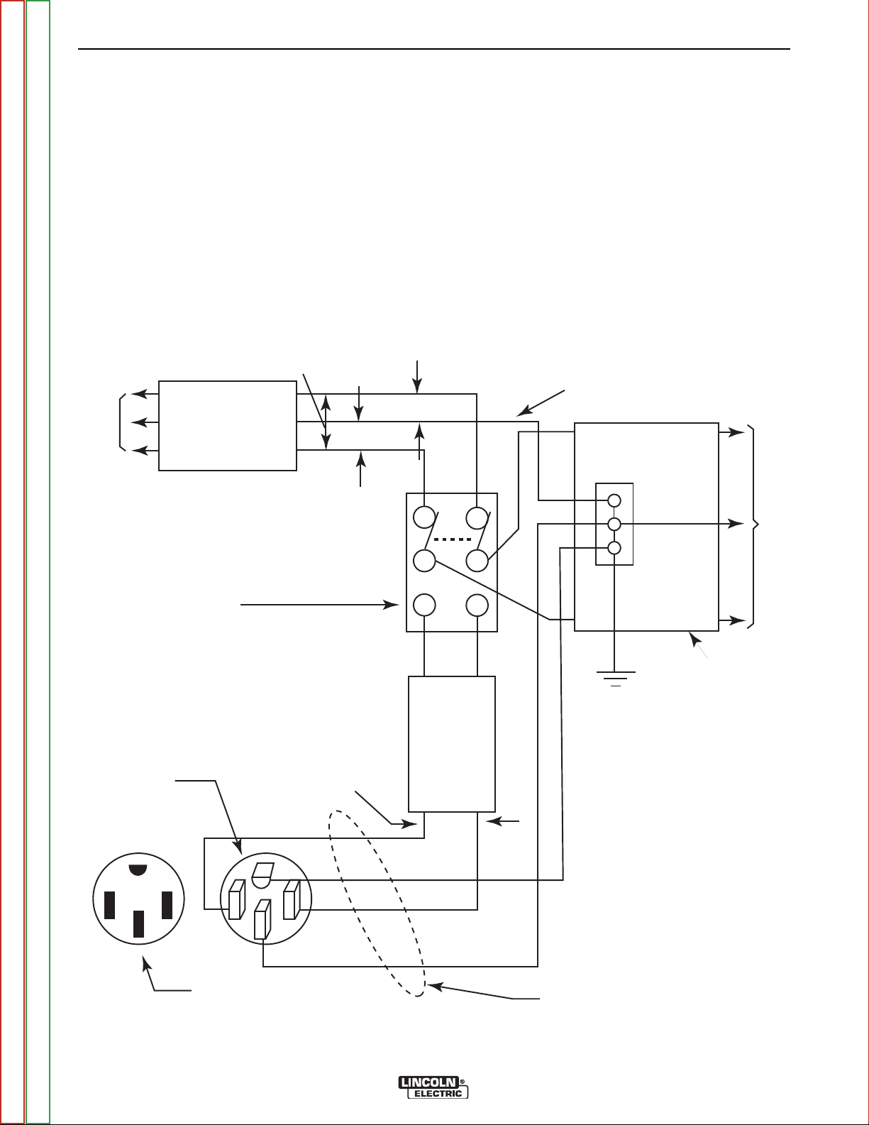
INSTALLATION
1. Install the double-pole, double-throw switch
between the power company meter and the
premises disconnect.
Switch rating must be the same as or greater than the
customer’s premises disconnect and service over current protection.
2. Take necessary steps to assure load is limited to
the capacity of the Vantage by installing a 50 amp,
240 VAC double-pole circuit breaker. Maximum
rated load for each leg of the 240 VAC auxiliary is
50 amperes. Loading above the rated output will
reduce output voltage below the allow-
Figure A1.1 Connection of the Vantage® 500 to Premises Wiring
able -10% of rated voltage, which may damage
appliances or other motor-driven equipment and
may result in overheating of the Vantage 500
engine.
3. Install a 50 amp 120/240 VAC plug (NEMA Type
14-50) to the double-pole circuit breaker using
four-conductor cable of the proper size and desired
length. (The 50 amp, 120/240 VAC plug is available in the optional K802R plug kit.)
4. Plug this cable into the 50 amp 120/240 volt receptacle on the Vantage 500 case front.
Return to Section TOC Return to Section TOC Return to Section TOC Return to Section TOC
Return to Master TOC Return to Master TOC Return to Master TOC Return to Master TOC
VANTAGE® 500
Page 17

B1.1 B1.1
TABLE OF CONTENTS - OPERATION SECTION
Operation - VANTAGE® 500 Deutz F3L912 (Code 10995)
Operating Instructions . . . . . . . . . . . . . . . . . . . . . . . . . . . . . . . . . . . . . . . . . . . . . . . . . . . . . . . . . . . . . . . .B1.2
Safety Instructions . . . . . . . . . . . . . . . . . . . . . . . . . . . . . . . . . . . . . . . . . . . . . . . . . . . . . . . . . . . . . . . . . . .B1.2
General Description . . . . . . . . . . . . . . . . . . . . . . . . . . . . . . . . . . . . . . . . . . . . . . . . . . . . . . . . . . . . . . . . . .B1.2
Recommended Applications . . . . . . . . . . . . . . . . . . . . . . . . . . . . . . . . . . . . . . . . . . . . . . . . . . . . . . . .B1.3
Design Features and Advantages . . . . . . . . . . . . . . . . . . . . . . . . . . . . . . . . . . . . . . . . . . . . . . . . . . . .B1.3
Controls and Settings . . . . . . . . . . . . . . . . . . . . . . . . . . . . . . . . . . . . . . . . . . . . . . . . . . . . . . . . . . . . . . . . .B1.4
Engine Controls . . . . . . . . . . . . . . . . . . . . . . . . . . . . . . . . . . . . . . . . . . . . . . . . . . . . . . . . . . . . . . . . . .B1.4
Welding Controls . . . . . . . . . . . . . . . . . . . . . . . . . . . . . . . . . . . . . . . . . . . . . . . . . . . . . . . . . . . . . . . . .B1.5
Auxiliary Power Controls . . . . . . . . . . . . . . . . . . . . . . . . . . . . . . . . . . . . . . . . . . . . . . . . . . . . . . . . . . .B1.6
Engine Operation . . . . . . . . . . . . . . . . . . . . . . . . . . . . . . . . . . . . . . . . . . . . . . . . . . . . . . . . . . . . . . . . . . . .B1.7
Starting the Engine . . . . . . . . . . . . . . . . . . . . . . . . . . . . . . . . . . . . . . . . . . . . . . . . . . . . . . . . . . . . . . .B1.7
Stopping the Engine . . . . . . . . . . . . . . . . . . . . . . . . . . . . . . . . . . . . . . . . . . . . . . . . . . . . . . . . . . . . . . .B1.7
Break-In Period . . . . . . . . . . . . . . . . . . . . . . . . . . . . . . . . . . . . . . . . . . . . . . . . . . . . . . . . . . . . . . . . . .B1.7
Typical Fuel Consumption . . . . . . . . . . . . . . . . . . . . . . . . . . . . . . . . . . . . . . . . . . . . . . . . . . . . . . . . . .B1.7
Welder Operation . . . . . . . . . . . . . . . . . . . . . . . . . . . . . . . . . . . . . . . . . . . . . . . . . . . . . . . . . . . . . . . . . . . .B1.8
Stick Welding . . . . . . . . . . . . . . . . . . . . . . . . . . . . . . . . . . . . . . . . . . . . . . . . . . . . . . . . . . . . . . . . . . . .B1.8
Constant Current (CC) Welding . . . . . . . . . . . . . . . . . . . . . . . . . . . . . . . . . . . . . . . . . . . . . . . . . . . . . .B1.8
Pipe Welding . . . . . . . . . . . . . . . . . . . . . . . . . . . . . . . . . . . . . . . . . . . . . . . . . . . . . . . . . . . . . . . . . . . .B1.8
TIG Welding . . . . . . . . . . . . . . . . . . . . . . . . . . . . . . . . . . . . . . . . . . . . . . . . . . . . . . . . . . . . . . . . . . . . .B1.8
Wire Feed (Constant Voltage) Welding . . . . . . . . . . . . . . . . . . . . . . . . . . . . . . . . . . . . . . . . . . . . . . .B1.10
Auxiliary Power Operation . . . . . . . . . . . . . . . . . . . . . . . . . . . . . . . . . . . . . . . . . . . . . . . . . . . . . . . . . . . .B1.10
Arc Gouging . . . . . . . . . . . . . . . . . . . . . . . . . . . . . . . . . . . . . . . . . . . . . . . . . . . . . . . . . . . . . . . . . . . .B1.10
Paralleling . . . . . . . . . . . . . . . . . . . . . . . . . . . . . . . . . . . . . . . . . . . . . . . . . . . . . . . . . . . . . . . . . . . . .B1.10
Return to Master TOC Return to Master TOC Return to Master TOC Return to Master TOC
Simultaneous Welding and Auxiliary Power Loads . . . . . . . . . . . . . . . . . . . . . . . . . . . . . . . . . . . . . . . . .B1.11
Extension Cord Recommendations . . . . . . . . . . . . . . . . . . . . . . . . . . . . . . . . . . . . . . . . . . . . . . . . . . . . .B1.11
VANTAGE® 500
Page 18

B1.2 B1.2
OPERATION
OPERATING INSTRUCTIONS
Read and understand this entire section before operating your Vantage® 500.
SAFETY INSTRUCTIONS
WARNING
Do not attempt to use this equipment until you
have thoroughly read all operating and maintenance manuals supplied with your machine. They
include important safety precautions: detailed
engine starting, operating, and maintenance
instructions and parts lists.
ELECTRIC SHOCK can kill.
• Do not touch electrically live parts or
electrodes with your skin or wet
clothing.
ENGINE EXHAUST can kill.
• Use in open, well ventilated areas or
vent exhaust outside
• Do not stack anything near the
engine.
MOVING PARTS can injure.
• Do not operate with doors open or
guards off.
• Stop engine before servicing.
• Keep away from moving parts
Only qualified personnel should operate this
equipment.
ADDITIONAL SAFETY PRECAUTIONS
Always operate the welder with the hinged door closed
and the side panels in place, as these provide maximum protection from moving parts and insure proper
cooling air flow.
• Insulate yourself from the work and
ground.
• Always wear dry insulating gloves.
FUMES AND GASES CAN BE
DANGEROUS.
• Keep your head out of fumes.
• Use ventilation or exhaust to remove
fumes from breathing zone.
WELDING SPARKS CAN CAUSE
FIRE OR EXPLOSION.
• Keep flammable material away.
• Do not weld on containers that have
held combustibles.
ARC RAYS CAN BURN.
• Wear eye, ear, and body protection.
GENERAL DESCRIPTION
The Vantage® 500 is a diesel engine-driven welding
power source. The machine uses a brush type alternating current generator for DC multi-purpose welding
and for 120/240 VAC auxiliary standby power. The
welding control system uses state of the art Chopper
Technology.
The generator has a single sealed bearing for maintenance free service. The rotor is a copper wound design
with two slip rings and brushes. The stator is wound
entirely with heavy gauge copper wire and insulated
with NEMA class F insulation material. The stator is
then impregnated with three layers of high quality varnish. After the stator is assembled using tie bars, the
entire assembly is covered with an environmental protective coating. These measures insure trouble-free
operation in the harshest environments.
The fuel tank is made from high density polyethylene
and holds 25 gallons (94.6 liters) of diesel fuel. This
will provide enough fuel to run for more than 12 hours
at full load.
The Deutz F3L-912 engine is equipped with a standard, heavy duty, combination fuel filter/water separator element.
Return to Section TOC Return to Section TOC Return to Section TOC Return to Section TOC
Return to Master TOC Return to Master TOC Return to Master TOC Return to Master TOC
VANTAGE® 500
Page 19

B1.3 B1.3
OPERATION
RECOMMENDED APPLICATIONS
WELDER
The Vantage® 500 provides excellent constant current
DC welding output for stick (SMAW) and TIG welding.
The Vantage® 500 also provides excellent constant
voltage DC welding output for MIG (GMAW) and
Innershield (FCAW) welding.
GENERATOR
The Vantage® 500 provides smooth 120/240 VAC output for auxiliary power and emergency standby power.
DESIGN FEATURES AND ADVANTAGES
K1639-2 VANTAGE® 500 DELUXE MODEL
FEATURES
FOR WELDING
• Excellent DC multi-purpose welding for stick, MIG,
TIG, cored wire and arc gouging applications.
• 30 to 500 amps output in five slope-controlled ranges
for out-of position and pipe electrodes, one constant
current output range for general purpose welding,
one constant voltage range for MIG wire and cored
wire welding and one 20-250 amp range for “Touch
Start” TIG welding.
• 100% duty cycle at 500 amps output and 50% duty
cycle at 575 amps output.
• Dual 3-digit output meters are provided (optional on
K1639-1) for presetting the weld amperage or voltage and displaying the actual amperage and voltage
during welding. The meters use superbrite L.E.D.'s
for improved readability in full sunlight.
LOOK-BACK FEATURE: After welding has stopped,
both displays will remain on for 7 seconds with the
last current and voltage value displayed. During this
time, the left-most decimal point in each display will
be FLASHING.
• Standard remote control capability with 14-pin and
6-pin connectors for easy connection of Lincoln
remote control accessories.
• An internal "Solid State" contactor allows for the
selection of "hot" or "cold" output terminals with a
toggle switch on the control panel.
FOR AUXILIARY POWER
• 12,000 watts of 120/240 VAC, 60Hz auxiliary power.
• Power for tools, 120/240 VAC lights, electric pumps
and for standby emergency power.
• Drive a 5 HP motor (provided it is started under no
load).
• Two 20 amp 120 VAC duplex receptacles for up to 40
amps of 120 VAC power.
• One 50 amp, 120/240 VAC dual voltage receptacle
for up to 50 amps of 240 VAC, and up to 50 amps per
side to separate branch circuits (not in parallel) of
120 VAC single-phase auxiliary power. Allows easy
connection to premises wiring.
• Weld and AC auxiliary power at the same time (within machine total capacity).
OTHER FEATURES
• Deutz 3-cylinder, air/oil cooled diesel engine.
Designed for long life, easy maintenance, and
excellent fuel economy.
• Engine protection system shuts the engine down for
low oil pressure, high oil temperature, or a broken
fan/engine alternator belt.
• Gauges for oil pressure, oil temperature, engine
alternator output, and fuel level.
• Indicator lights for Engine Protection, and Battery
(engine alternator low output/broken belt).
• Engine hour meter standard on all models.
• Extended range 25 gallon (94.6 l) fuel tank.
• Automatic idler reduces engine speed when not
welding or drawing auxiliary power. This feature
reduces fuel consumption and extends engine life.
• Compact size fits crosswise in full size pickup truck.
• Single-side engine service.
• Copper alternator windings and high temperature
insulation for dependability and long life.
• New paint system on case and base for outstanding
corrosion protection.
Return to Section TOC Return to Section TOC Return to Section TOC Return to Section TOC
• “Arc Control” potentiometer in Wire and Stick modes
for precise adjustment of arc characteristics.
• Advanced circuitry to prevent pop-outs in the five
slope modes.
Return to Master TOC Return to Master TOC Return to Master TOC Return to Master TOC
VANTAGE® 500
Page 20
B1.4 B1.4
OPERATION
CONTROLS AND SETTINGS
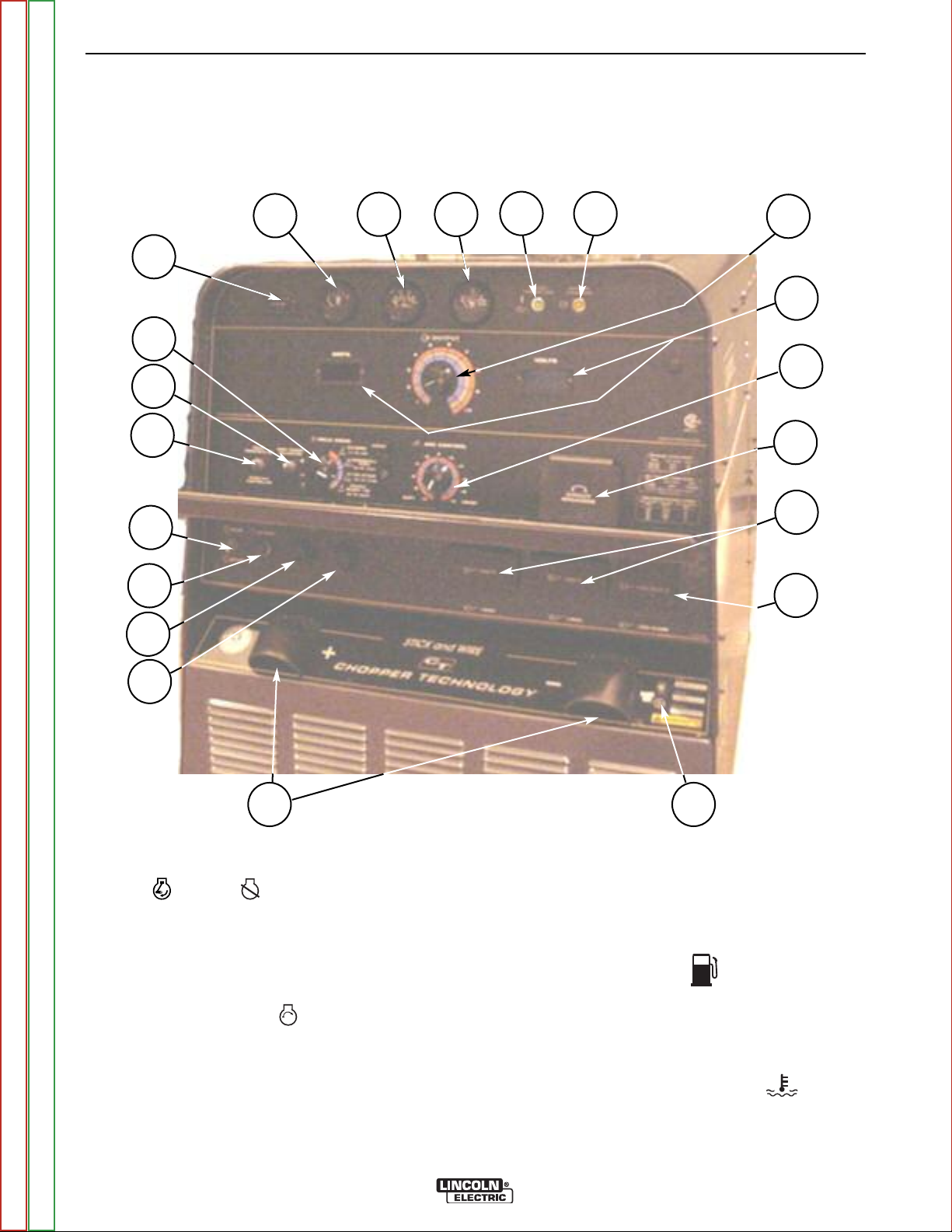
All welder and engine controls are located on the case front panel. Refer to Figure B.1 and the explanations that follow.
Figure B1.1 Case Front Panel Controls
11
14
13
1
2
15
4
5
6
7
8
9
3
10
12
19
20
18
Return to Section TOC Return to Section TOC Return to Section TOC Return to Section TOC
16
17
ENGINE CONTROLS (Items 1 through 9)
1. RUN STOP SWITCH
Toggling the switch to the RUN position energizes
the fuel solenoid for approximately 30 seconds. The
engine must be started within that time or the fuel
solenoid will denergize, and the switch must be toggled to reset the timer.
2. START PUSHBUTTON
Energizes the starter motor to crank the engine. With
the engine "Run / Stop" switch in the "Run" position,
push and hold the Start button to crank the engine;
release as the engine starts. Do not press while
engine is running since this can cause damage to
the ring gear and/or starter motor
Return to Master TOC Return to Master TOC Return to Master TOC Return to Master TOC
21
3. HOUR METER
The hour meter displays the total time that the engine
has been running. This meter is a useful indicator for
scheduling preventive maintenance.
4. FUEL LEVEL GAUGE
Displays the level of diesel fuel in the fuel tank.
The operator must watch the fuel level closely to
prevent running out of fuel and possibly having to
bleed the system.
5. ENGINE TEMPERATURE GAUGE
The gauge displays the engine coolant temperature.
VANTAGE® 500
Page 21

B1.5 B1.5
OPERATION
6. OIL PRESSURE GAUGE
The gauge displays the engine oil pressure when the
engine is running.
7. ENGINE PROTECTION
The yellow engine protection light remains off with
proper oil pressure and under normal operating temperatures. If the light turns on, the engine protection
system will stop the engine. Check for proper oil and
coolant levels and add oil and/or coolant if necessary. Check for loose or disconnected leads at the oil
pressure sender located on the engine. The light will
remain on when the engine has been shut down as
long as the Run/Stop switch is in the Run position.
NOTE: This engine is equipped with an electronic
governor system. The engine speed ramps
up during a warm up period. The complete
cycle takes approximately 3 minutes. This
allows the engine cylinder temperature to
build up slowly before going to full speed.
This feature is bypassed if the engine is
already warm. The Engine may produce
“White Smoke” for a few minutes at low temperatures. Do not apply a load to the
machine during the warm up period.
8. BATTERY CHARGING LIGHT
The yellow engine alternator light is off when battery
charging system is functioning normally. If light turns
on the alternator or the voltage regulator may not be
operating correctly. The light will remain on when the
engine is stopped and the Run/Stop switch is in the
Run position.
WELDING CONTROLS (Items 9 through 17)
9. OUTPUT CONTROL: The OUTPUT dial is used to
preset the output voltage or current as displayed on the
digital meters for the four welding modes. When in the
CC-STICK, DOWNHILL PIPE or CV-WIRE modes and
when a remote control is connected to the 6-Pin or 14Pin Connector, the auto-sensing circuit automatically
switches the OUTPUT CONTROL from control at the
welder to the remote control. In the CV-WIRE mode,
when the wire feeder control cable is connected to the
14-pin connector the auto-sensing circuit automatically
makes OUTPUT CONTROL inactive and the wire feeder voltage control (if present) active.
When in the TOUCH START TIG mode and when a
Amptrol is connected to the 6-pin Connector, the OUTPUT dial is used to set the maximum current range of
the CURRENT CONTROL of the Amptrol.
10. DIGITAL OUTPUT METERS: (Optional)
The digital meters allow the output voltage (CV-WIRE
mode) or current (CC-STICK, DOWNHILL PIPE and
TIG modes) to be set prior to welding using the OUTPUT control knob. During welding, the meters display
the actual output voltage (VOLTS) and current (AMPS).
A memory feature holds the display of both meters on
the seven seconds after welding is stopped. This
allows the operator to read the actual current and voltage just prior to when welding was ceased. While the
display is being held the left-most decimal point in each
display will be flashing. The accuracy of the meters is ±
3%.
11. WELD MODE SELECTOR SWITCH:
(Provides four selectable welding modes)
CV-WIRE
DOWNHILL PIPE
CC-STICK
TOUCH START TIG
12. ARC CONTROL:
The ARC CONTROL WIRE/STICK knob is active in the
WIRE and STICK modes, and has different functions in
these modes. This control is not active in the TIG
mode.
CC-STICK mode: In this mode, the ARC CONTROL
knob sets the short circuit current (arc-force) during
stick welding. Increasing the number from -10(Soft) to
+10 (Crisp) increases the short circuit current and prevents sticking of the electrode to the plate while welding. This can also increase spatter. It is recommended
that the ARC CONTROL be set to the minimum number without electrode sticking. Start with a setting at 0.
DOWNHILL PIPE mode: In this mode, the ARC CONTROL knob sets the short circuit current (arc-force)
during stick welding to adjust for a soft or a more forceful digging arc (Crisp). Increasing the number from -10
(Soft) to +10 (Crisp) increases the short circuit current
which results in a more forceful digging arc. Typically a
forceful digging arc is preferred for root and hot passes. A softer arc is preferred for fill and cap passes
where weld puddle control and deposition (“stacking” of
iron) are key to fast travel speeds. It is recommended
that the ARC CONTROL be set initially at 0.
CV-WIRE mode: In this mode, turning the ARC CONTROL knob from -10(soft) to +10(crisp) changes the
arc from soft and washed-in to crisp and narrow. It acts
as an inductance/pinch control. The proper setting
depends on the procedure and operator preference.
Start with a setting of 0.
Return to Section TOC Return to Section TOC Return to Section TOC Return to Section TOC
Return to Master TOC Return to Master TOC Return to Master TOC Return to Master TOC
VANTAGE® 500
Page 22

B1.6 B1.6
OPERATION
13. WELDING TERMINALS SWITCH
In the WELD TERMINALS ON position, the output is
electrically hot all the time. In the REMOTELY CONTROLLED position, the output is controlled by a wire
feeder or amptrol device, and is electrically off until a
remote switch is depressed.
14. WIRE FEEDER VOLTMETER SWITCH:
Matches the polarity of the wire feeder voltmeter to the polarity of the electrode.
15. 6 - PIN CONNECTOR
For attaching optional remote control equipment. Includes
auto-sensing remote control circuit.
16. 14 - PIN CONNECTOR
For attaching wire feeder control cables. Includes contactor
closure circuit, auto-sensing remote control circuit, and
120VAC and 42VAC power.
NOTE: When a wire feeder with a built in welding voltage control is connected to the 14-pin connector, do not connect anything to the 6-pin connector.
21. 120VAC SINGLE PHASE RECEPTACLES
These two 120VAC (5-20R) receptacles with GFCI
protection provide 120VAC single phase for auxiliary
power. Each receptacle has a 20 amp total rating.
They are designed to protect the user from the hazards of ground faults. When the GFCI has tripped
there will be no voltage available from the receptacle.
Refer to the AUXILIARY POWER RECEPTACLES
section in the installation chapter for further information about these receptacles. Also refer to the AUXILIARY POWER OPERATION section later in this
chapter.
22. GROUND STUD
Provides a connection point for connecting the
machine case to earth ground. Refer to “MACHINE
GROUNDING” in the Installation chapter for proper
machine grounding information.
7. WELD OUTPUT TERMINALS + AND –
These 1/2” - 13 studs with flange nuts provide welding connection points for the electrode and work cables. For positive
polarity welding the electrode cable connects to the “+” terminal and the work cable connects to this “–” terminal. For negative polarity welding the work cable connects to the “+” terminal and the electrode cable connects to this “–” terminal.
AUXILIARY POWER CONTROLS (Items 18-21)
18. 120/240 VAC SINGLE PHASE RECEPTACLE
This is a 120/240VAC (14-50R) receptacle that provides
240VAC or can be split for 120VAC single phase auxiliary
power. This receptacle has a 50 amp rating. Refer to the AUXILIARY POWER RECEPTACLES section in the installation
chapter for further information about this receptacle. Also refer
to the AUXILIARY POWER OPERATION section later in this
chapter.
20. CIRCUIT BREAKERS
These circuit breakers provide separate overload
current protection for each 120V circuit at the 240V
single phase receptacle, each 120V single phase
receptacle, the 240V three phase receptacle, the
120VAC in the 14-Pin connector, the 42VAC in the
14-Pin connector and battery circuit overload protection.
Return to Section TOC Return to Section TOC Return to Section TOC Return to Section TOC
Return to Master TOC Return to Master TOC Return to Master TOC Return to Master TOC
VANTAGE® 500
Page 23

B1.7 B1.7
OPERATION
ENGINE OPERATION
STARTING THE ENGINE
1. Open the engine compartment door and check that
the fuel shutoff valve is in the open position (lever to
be in line with the hose).
2. Check for proper oil level and coolant level. Close
engine compartment door.
3. Remove all plugs connected to the AC power recep-
tacles.
4. Set IDLER switch to “AUTO”.
5. Set the RUN/STOP switch to “RUN”. Observe that
the engine protection and battery charging lights are
on. The engine protection light may turn off after 5
seconds or remain on until the engine is started.
6. Within 30 seconds, press and hold the engine
START button until the engine starts. If the engine
does not start within 30 seconds the RUN/STOP
switch must be returned to the STOP position, then
return to step 5.
7. Release the engine START button when the engine
starts.
8. Check that the engine protection and battery charg-
ing lights are off. Investigate any indicated problem.
NOTE: The engine will go through a 3 minute warm-up
cycle if cold. If the engine coolant is still warm
from recent operation, the engine will go immediately to high idle and then to low idle if the idle
switch is in the “AUTO” position.
IMPORTANT
IN ORDER TO ACCOMPLISH THIS BREAK-IN, THE UNIT
SHOULD BE SUBJECTED TO HEAVY LOADS, WITHIN
THE RATING OF THE MACHINE. AVOID LONG IDLE RUNNING PERIODS.
TYPICAL FUEL CONSUMPTION
Refer to Table B1.1 for typical fuel consumption of the VAN-
TAGE 500 Engine for various operating scenarios.
Table B1.1 – DEUTZ F3L 912
ENGINE FUEL CONSUMPTION
High Idle
No Load
1900 rpm
DC-CC
Welding
500A @40V
Auxiliary Power
12,000 VA
Deutz F3L 912
44.2 HP
@1800 rpm
.66 gallons/hour
(2.50 liters/hour)
1.94 gallons/hour
(7.34 liters/hour)
1.31 gallons/hour
(4.96 liters/hour)
Running Time
for 25 Gallons
(Hours)
37.9
12.9
19.1
Return to Section TOC Return to Section TOC Return to Section TOC Return to Section TOC
COLD WEATHER STARTING
With a fully charged battery and the proper weight oil,
the engine should start satisfactorily even down to
about 0°F(-18°C). If the engine must be frequently
started below 10°(-12°C), it may be desirable to install
the optional ether start kit (K887-1). Installation and
operating instructions are included in the kits.
STOPPING THE ENGINE
Switch the RUN/STOP switch to “STOP”. This turns off
the voltage supplied to the shutdown solenoid. A backup shutdown can be accomplished by shutting off the
fuel valve located on the fuel line.
BREAK-IN PERIOD
The engine used to supply power for your welder is a heavy
duty, industrial engine. It is designed and built for rugged use.
It is very normal for any engine to use small quantities of oil
until the break-in is accomplished. Check the oil level twice a
day during the break-in period. In general this takes 50 to 100
hours of operation.
Return to Master TOC Return to Master TOC Return to Master TOC Return to Master TOC
VANTAGE® 500
Page 24

B1.8 B1.8
OPERATION
WELDER OPERATION
DUTY CYCLE
Duty Cycle is the the ratio of the uninterrupted on-load
duration to 10 minutes. The total time period of one
complete on-load and no-load cycle is 10 minutes. For
example, in the case of a 60% duty cycle, load is
applied continuously for 6 minutes followed by a noload period of 4 minutes.
STICK WELDING MODE
The Vantage can be used with a broad range of DC
stick electrodes.
The MODE switch provides two stick welding settings
as follows:
CC-STICK MODE
The CC-STICK position of the MODE switch is
designed for horizontal, vertical-up and overhead welding with all types of electrodes, especially low hydrogen.
The OUTPUT CONTROL knob adjusts the full output
range for stick welding.
The ARC CONTROL knob sets the short circuit (arcforce) current during stick welding. Increasing the number from -10 (Soft) to +10 (Crisp) increases the short
circuit current and prevents sticking of the electrode to
the plate while welding. This can also increase spatter.
It is recommended that the ARC CONTROL be set to
the minimum number without electrode sticking. Start
with the knob set at 0.
DOWNHILL PIPE MODE
This slope controlled setting is intended for “out-of-position” and “down hill” pipe welding where the operator
would like to control the current level by changing the
arc length. The OUTPUT CONTROL knob adjusts the
full output range for pipe welding.
The ARC CONTROL knob sets the short circuit current
(arc-force) during stick welding to adjust for a soft or a
more forceful digging arc (Crisp). Increasing the number
from -10 (Soft) to +10 (Crisp) increases the short circuit
current which results in a more forceful digging arc.
Typically a forceful digging arc is preferred for root and
hot passes. A softer arc is preferred for fill and cap passes where weld puddle control and deposition (“stacking”
of iron) are key to fast travel speeds. It is recommended that the ARC CONTROL be set initially at 0.
TOUCH START TIG MODE
The Vantage® 500 can be used in a wide variety of DC
TIG welding applications.
The TOUCH START TIG setting of the MODE switch is
for DC TIG (Tungsten Inert Gas) welding. To initiate a
weld, the OUTPUT CONTROL knob is first set to the
desired current and the tungsten is touched to the work.
During the time the tungsten is touching the work there
is very little voltage or current and, in general, avoids
tungsten contamination. Then, the tungsten is gently lifted off the work in a rocking motion, which establishes
the arc.
To stop the arc, simply lift the TIG torch away from the
work piece. When the arc voltage reaches approximately 30 volts, the arc will go out and the machine will
automatically reset to the touch start current level. The
tungsten may then be retouched to the work piece to
restrike the arc. The arc may also be started and
stopped with an Amptrol or Arc Start Switch.
The ARC CONTROL is not active in the TIG mode.
In general the ‘Touch Start’ feature avoids tungsten contamination without the use of a Hi-frequency unit. If the
use of a high frequency generator is desired, the K9302 TIG Module can be used with the Vantage. The settings are for reference.
The Vantage is equipped with the required R.F. bypass
circuitry for the connection of high frequency generating equipment.
The Vantage and any high frequency generating equipment must be properly grounded. See the K930-2 TIG
Module operating manuals for complete instructions on
installation, operation, and maintenance.
When using the TIG Module, the OUTPUT control on
the Vantage is used to set the maximum range of the
CURRENT CONTROL on the TIG Module or an Amptrol
if connected to the TIG Module.
Return to Section TOC Return to Section TOC Return to Section TOC Return to Section TOC
Return to Master TOC Return to Master TOC Return to Master TOC Return to Master TOC
VANTAGE® 500
Page 25

B1.9 B1.9
OPERATION
TABLE B1.2 – TYPICAL CURRENT RANGES1FOR TUNGSTEN ELECTRODES
2
Approximate Argon Gas Flow Rate
DCEN (-) DCEP (+) C.F.H. (l/min.)
Tungsten
Electrode 1%, 2% 1%, 2% TIG TORCH
Diameter Thoriated Thoriated Nozzle
in. (mm) Tungsten Tunsten Aluminum Stainless Steel Size
0.010 (.25) 2-15
0.020 (.50) 5-20
0.40 (1.0) 15-80
3
3
3
3-8 (2-4) 3-8 (2-4) #4, #5, #6
5-10 (3-5) 5-10 (3-5)
5-10 (3-5) 5-10 (3-5)
4, 5
1/16 (1.6) 70-150 10-20 5-10 (3-5) 9-13 (4-6) #5, #6
3/32 (2.4) 150-250 15-30 13-17 (6-8) 11-15 (5-7) #6, #7, #8
1/8 (3.2) 250-400 25-40 15-23 (7-11) 11-15 (5-7)
5/32 (4.0) 400-500 40-55 21-25 (10-12) 13-17 (6-8) #8, #10
3/16 (4.8) 500-750 55-80 23-27 (11-13) 18-22 (8-10)
1/4 (6.4) 750-1000 80-125 28-32 (13-15) 23-27 (11-13)
1
When used with argon gas. The current ranges shown must be reduced when using argon/helium or pure helium shielding gases.
2
Tungsten electrodes are classified as follows by the American Welding Society (AWS):
2
Though not yet recognized by the AWS, Ceriated Tungsten is now widely accepted as a substitute for 2% Thoriated Tungsten in AC and DC
applications.
3
DCEP is not commonly used in these sizes.
4
TIG torch nozzle “sizes” are in multiples of 1/16ths of an inch:
5
TIG torch nozzles are typically made from alumina ceramic. Special applications may require lava nozzles, which are less prone to breakage, but cannot withstand high temperatures and high duty cycles.
Pure EWP
1% Thoriated EWTh-1
2% Thoriated EWTh-2
# 4 = 1/4 in. (6 mm) # 7 = 7/16 in. (11 mm)
# 5 = 5/16 in. (8 mm) # 8 = 1/2 in. (12.5 mm)
# 6 = 3/8 in. (10 mm) #10 = 5/8 in. (16 mm)
Return to Section TOC Return to Section TOC Return to Section TOC Return to Section TOC
VANTAGE 500 SETTINGS WHEN USING THE K799
HI-FREQ UNIT
• Set the WELD MODE switch to the 20-250 setting
(TIG).
• Set the IDLER switch to the HIGH position.
• Set the WELDING TERMINALS switch to the WELD
TERMINALS ON position. This will close the solid
state contactor and provide an always “hot” electrode.
NOTE: This is necessary because the K799 circuitry
does not provide the proper signal to open and close
the solid state contactor in the Vantage 500.
Return to Master TOC Return to Master TOC Return to Master TOC Return to Master TOC
VANTAGE 500 SETTINGS WHEN USING A K930-[ ]
TIG MODULE
• Set the WELD MODE switch to the 20-250 setting
(TIG).
• Set the IDLER switch to the AUTO position.
• Set the WELDING TERMINALS switch to the
REMOTELY CONTROLLED position. This will keep
the solid state contactor open and provide a “cold”
electrode until the triggering device (Amptrol or Arc
Start Switch) is pressed.
VANTAGE® 500
Page 26

B1.10 B1.10
OPERATION
WIRE FEED (CONSTANT VOLTAGE)
WELDING
Connect a wire feeder to the Vantage® 500 and set
welder controls according to the instructions listed earlier in this section. See the operator’s manual for the
wire feeder or the “Diagrams” section of this manual
for connecting instructions of various Lincoln wire feeders.
The Vantage® 500 in the CV-WIRE position can be
used with a broad range of flux cored wire (Innershield
and Outershield) electrodes and solid wires for MIG
welding (GMAW). Welding can be finely tuned using
the ARC CONTROL.
Some recommended Innershield electrodes are: NR311, NS-3M, NR-207, NR-203 Ni 1%, NR-204-H.
Recommended Outershield electrodes are: 0S-70, 0S71M.
Some recommended solid wires for MIG welding are:
.035 (0.9 mm), .045 (1.1 mm) and .052 (1.3 mm), L-50
and L-56, .035 (0.9 mm) and .045 (1.1 mm) Blue Max
MIG 308 LS.
For any electrodes, including the above recommendations, the procedures should be kept within the rating of
the machine. For additional electrode information, see
Lincoln publications N-675, GS-100 and GS-210.
The auxiliary power receptacles should only be used
with three-wire grounded type plugs or approved double insulated tools with two wire plugs.
The current rating of any plug used with the system
must be at least equal to the current capacity of the
associated receptacle.
SIMULTANEOUS WELDING AND
AUXILIARY POWER LOADS
It must be noted that the above auxiliary power ratings
are with no welding load. Simultaneous welding and
power loads are specified in Table B1.3. The permissible currents shown assume that current is being
drawn from either the 120 VAC or 240 VAC supply (not
both at the same time).
ARC GOUGING
For optimal performance when arc gouging, set the
Vantage® 500 WELD MODE switch to the CC - STICK
position, and the ARC CONTROL to 10.
Set the OUTPUT knob to adjust output current to the
desired level for the gouging electrode being used
according to the ratings in the following table:
Electrode Current Range
Diameter (DC, electrode positive)
AUXILIARY POWER OPERATION
Full power is available regardless of the welding control
settings, if no welding current is being drawn.
The auxiliary power of the Vantage® 500 consists of
two 20 Amp-120VAC (5-20R) duplex receptacles and
one 50 Amp-120/240 VAC (14-50R) receptacle. The
120/240VAC receptacle can be split for single phase
120 VAC operation.
The auxiliary power capacity is 12,000 watts of 60 Hz,
single phase power. The auxiliary power capacity rating
in watts is equivalent to volt-amperes at unity power
factor. The maximum permissible current of the 240
VAC output is 50 A. The 240 VAC output can be split to
provide two separate 120 VAC outputs with a maximum permissible current of 50 A per output to two separate 120 VAC branch circuits. Output voltage is within
± 10% at all loads up to rated capacity.
NOTE: The 120/240V receptacle has two 120V out-
puts of different phases and cannot be paralleled.
1/8” 30-60 Amps
5/32” 90-150 Amps
3/16” 150-200 Amps
1/4” 200-400 Amps
5/16” 250-400 Amps
3/8” 350-575 Amps*
* Maximum current setting is limited to the Vantage 500
maximum of 575 Amps.
PARALLELING
When paralleling machines in order to combine their
outputs, all units must be operated in the CC - STICK
mode only. To achieve this, turn the WELD MODE
switch to the CC - STICK position. Operation in other
modes may produce erratic outputs and large output
iimbalances between the units.
Return to Section TOC Return to Section TOC Return to Section TOC Return to Section TOC
Return to Master TOC Return to Master TOC Return to Master TOC Return to Master TOC
VANTAGE® 500
Page 27

B1.11 B1.11
OPERATION
TABLE B1.3 Vantage 500 Duetz Simultaneous Welding and Power Loads
Welding Output Permissible Power Watts Permissible Auxiliary
at NEMA Voltage (Unity Power Factor) Current in Amperes
(V=.04I + 20) @ 120VAC * +/- 10% @ 240 VAC +/- 10%
0-250A/30V 12,000 100** 50
350A/34V 8,100 68** 34
400A/36V 5,600 46 23
450A/38V 2,900 24 12
500A/40V 000
* Each duplex receptacle is limited to 20 amps.
** Not to exceed 50A per 120 VAC branch circuit when splitting the 240 VAC output.
EXTENSION CORD
RECOMMENDATIONS
An extension cord can be used with the auxiliary power
outputs as long as it is of ample size. Table B1.4 lists
permissible extension cord lengths based on conductor size and auxiliary power output.
Current
(Amps)
15
15
20
20
25
30
38
50
TABLE B1.4 – VANTAGE 500 EXTENSION CORD LENGTH RECOMMENDATIONS
Voltage
(Volts)
120
240
120
240
240
240
240
240
Load
(Watts)
1800
3600
2400
48010
6000
7200
9000
12000
Maximum Allowable Cord Length in ft. (m) for Conductor Size
14 AWG 12 AWG 10 AWG 8 AWG 6 AWG 4 AWG
30
60
(9)
(18)
Conductor size is based on maximum 2.0% voltage drop.
40
75
30
60
(12)
(23)
(9)
(18)
75
150
50
100
90
75
(23)
(46)
(15)
(30)
(27)
(23)
125
225
88
175
150
120
100
(38)
(69)
(27)
(53)
(46)
(37)
(30)
175
350
138
275
225
175
150
125
(53)
(107)
(42)
(84)
(69)
(53)
(46)
(38)
300
600
225
450
250
300
250
200
(91)
(183)
(69)
(137)
(76)
(91)
(76)
(61)
Return to Section TOC Return to Section TOC Return to Section TOC Return to Section TOC
Return to Master TOC Return to Master TOC Return to Master TOC Return to Master TOC
VANTAGE® 500
Page 28

B1.12 B1.12
NOTES
Return to Section TOC Return to Section TOC Return to Section TOC Return to Section TOC
Return to Master TOC Return to Master TOC Return to Master TOC Return to Master TOC
VANTAGE® 500
Page 29

C1.1 C1.1
TABLE OF CONTENTS - ACCESSORIES SECTION
Accessories - VANTAGE® 500 Deutz F3L912 (Code 10995)
Options/Accessories . . . . . . . . . . . . . . . . . . . . . . . . . . . . . . . . . . . . . . . . . . . . . . . . . . . . . . . . . . . . . . . . . .C1.1
Optional Field Installed Accessories . . . . . . . . . . . . . . . . . . . . . . . . . . . . . . . . . . . . . . . . . . . . . . . . . .C1.2
Plasma Cutting Option . . . . . . . . . . . . . . . . . . . . . . . . . . . . . . . . . . . . . . . . . . . . . . . . . . . . . . . . . . . . .C1.2
TIG Welding Options . . . . . . . . . . . . . . . . . . . . . . . . . . . . . . . . . . . . . . . . . . . . . . . . . . . . . . . . . . . . . .C1.3
High Frequency Generators for TIG Applications . . . . . . . . . . . . . . . . . . . . . . . . . . . . . . . . . . . . . . . .C1.3
Wire Feeder Options . . . . . . . . . . . . . . . . . . . . . . . . . . . . . . . . . . . . . . . . . . . . . . . . . . . . . . . . . . . . . .C1.3
Return to Master TOC Return to Master TOC Return to Master TOC Return to Master TOC
VANTAGE® 500
Page 30

C1.2 C1.2
ACCESSORIES
OPTIONAL FIELD INSTALLED ACCESSORIES
K802N POWER PLUG KIT - Provides four 120V plugs rated at 20
amps each and one dual voltage, full KVA plug rated at 120/240V,
50 amps. The 20 amp/120V plug may not be compatible with NEMA
common household receptacles.
K802R POWER PLUG KIT - Provides four 120V plugs rated 15
amps each and one dual voltage, full KVA plug rated at 120/240V,
50 amps. The 15 amp/120V plug is compatible with NEMA common
household receptacles.
K857 25 ft. (7.5 m) or K857-1 100 ft. (30.4 m) REMOTE CONTROL - Portable control provides same dial range as the output
control on the welder from a location up to the specified length
from the welder. Has convenient plug for easy connection to the
welder. The VANTAGE® 500 is equipped with a 6-pin connector
for connecting the remote control.
K704 ACCESSORY SET - Includes 35 feet (10 m) of
electrode cable and 30 feet (9 m) of work cable, headshield, Filter plate, work clamp and electrode holder.
Cable is rated at 500 amps, 60% duty cycle.
K2641-2 FOUR WHEELED STEERABLE YARD
TRAILER
For in plant and yard towing.
Hitch™, a 2” Ball and Lunette Eye combination hitch.
K2636-1 TRAILER - Two-wheeled trailer with optional fender
and light package. For highway use, consult applicable federal,
state, and local laws regarding possible additional require-
Comes standard with a Duo-Hitch™, a 2” Ball and Lunette
ments.
Eye combination hitch
K2636-1 Trailer
K958-1 Ball Hitch
K958-2 Lunette Eye Hitch
K2639-1 Fender & Light Kit
K2640-1 Cable Rack
, a fender & a light package. Order:
Comes standard with a Duo-
T12153-9 Full-KVA Power Plug-One dual voltage
plug rated at 120/240V, 50 amps, single phase.
K2356-1 Control Panel Cover Kit-Clear plexiglass
cover to protect control panel from dirt and debris, and
to visually monitor machine operation. Lockable to deter
vandalism.
K2340-1 Lockable Fuel Cap / Flash Arrester Kit-For
use in locations where flash arrester safety is required.
Lockable fuel cap prevents tampering with fuel. Green
cap color provides a visual reminder to use diesel when
refueling.
PLASMA CUTTING
K1581-1 Pro-cut 80 - Cuts mild steel using the 3-phase
AC generator power from the engine driven welder.
NOTE: Other Linclon plasma cutters, both single phase
Pipe Thawing with an arc welder can cause fire,
explosion, damage to electric wiring or to the arc
welder if done improperly. The use of an arc welder
for pipe thawing is not approved by the CSA, nor is
it recommended or supported by Lincoln Electric.
------------------------------------------------------------------------
and 3 phase can be used as long as the rating
of the receptacle is not exceeded
WARNING
Return to Section TOC Return to Section TOC Return to Section TOC Return to Section TOC
K887-1 ETHER START KIT - Provides maximum cold weather
starting assistance for frequent starting below
Required Ether tank is not provided with kit.
K899-1 SPARK ARRESTOR KIT - Easily mounts to standard
muffler.
K949-1 Oil Drain Kit - includes ball valve, hose and clamp.
K1816-1 Full KVA Adapter Kit - Plugs into the
120/240V NEMA 14-50R receptacle on the case front
(which accepts 4-prong plugs) and converts it to a
NEMA 6-50R receptacle (which accepts 3-prong plugs)
for connection to Lincoln Equipment with a NEMA 650P plug,
Return to Master TOC Return to Master TOC Return to Master TOC Return to Master TOC
10°(-12°C)
.
VANTAGE® 500
Page 31

C1.3 C1.3
ACCESSORIES
TIG OPTIONS
K1783-9 PTA-26V TIG Torch
Air Cooled 200 amp torch (2 piece) equipped with valve
for gas flow control. 25 ft. (7.6m) length.
KP509 Magnum Parts Kit for PTA-26V TIG Torch
Magnum Parts Kit provides all the torch accessories
you need to start welding. Parts kit provides collets,
collet bodies, a black cap, alumina nozzles and tungstens in a variety of sizes, all packaged in an easy to
carry reclosable sack.
K870 Foot Amptrol®-Varies current while welding for
making critical TIG welds and crater filling. Depress
pedal to increase current. Depressing pedal fully
achieves maximum set current. Fully raising the pedal
finishes the weld and starts the after flow cycle on systems so equipped. Includes 25 ft. (7.6m) control cable.
K963-3 Hand Amptrol®-Varies current for making critical TIG welds. Fastens to the torch for convenient
thumb control. Comes with a 25 ft. (7.6m) cable. (One
size fits all Pro-Torch TIG Torches.)
K2347-1 Precision TIG 185 Ready-Pak
For AC TIG Welding with square wave performance
use the AC generator of the Engine-Driven Welder to
supply the power. Easy setup. Includes torch, foot
amptrol, gas regulator and hose. Requires the K18161 Full KVA adapter kit.
K2350-1 Invertec® V205-T AC/DC One-Pak™ Package
For AC TIG welding with square wave performance,
use the AC generator of the engine-driven welder to
supply the power. Easy setup. Includes torch, parts
kit, regulator and hose kit, Twist-Mate™ torch adapter,
work cable with Twist-Mate end and foot Amptrol®.
KP653-3/32 Drive Roll and Guide Tube Kit (for LN-25)
For .068-3/32” (1.8-2.4mm) cored or solid steel wire.
K1802-1 Magnum® 300 MIG Gun
For .035-.045 (0.9-1.2mm) gas shielded wire. Includes
15 ft. gun and cable assembly and connector kit.
KP653-035S Drive Roll and Guide Tube Kit (for LN-25)
For .035-.040” (0.9-1.0mm) solid steel wire.
K2613-1 LN-25 PRO PORTABLE WIRE FEEDER-The
MAXTRAC® wire drive enhances performance, while the
replacement case, and many other upgrade options that can
be installed in less then five minutes aid in the serviceability.
KP1697-5/64 Drive Roll Kit- Includes: 2 polished U
groove drive rolls, outer wire guide and inner wire guide
for solid core wire. (Used on LN-25 Pro)
KP1697-068 Drive Roll Kit- Includes: 2 polished U
groove drive rolls, outer wire guide and inner wire guide
for solid core wire. (Used on LN-25 Pro)
KP1696-1 Drive Roll Kit- Includes: 2 V groove drive
rolls and inner wire guide for Steel Wires. (Used on LN25 Pro)
K487-25 Magnum SG Spool Gun
Hand held semiautomatic wire feeder. Requires SG
Control Module and Input Cable.
K488 SG Control Module
The Interface between the power source and the spool
gun. Provides control of the wire speed and gas flow.
For use with a spool gun.
Return to Section TOC Return to Section TOC Return to Section TOC Return to Section TOC
HIGH FREQUENCY GENERATORS FOR
TIG APPLICATIONS
The K799 Hi-Freq Unit (obsolete) and the K930- [ ] TIG
Modules are suitable for use with the Vantage 500.
The Vantage® 500 is equipped with the required RF
bypass circuitry for the connection of high frequency
generating equipment. The high frequency bypass network supplied with the K799 Hi-Freq Unit does NOT
need to be installed into the Vantage® 500.
The Vantage® 500 and any high frequency-generating
equipment must be properly grounded. See the K799
Hi-Freq Unit and the K930-AII TIG Module operating
manuals for complete instructions on installation, operation, and maintenance.
WIRE FEEDER OPTIONS
K449 LN-25 Wire Feeder
Portable CC/CV unit for flux-cored and MIG welding.
Includes Gas Solenoid & Internal Contactor.
K126-2 Magnum® 350 Innershield Gun (for LN-25)
For self-shielded wire with 15 ft. (4.5m) cable. For
.062-3/32” (1.6-2.4mm) wire.
Return to Master TOC Return to Master TOC Return to Master TOC Return to Master TOC
K691-10 Input Cable (For SG Control Module)
For Lincoln engine power sources with 14-pin MS-type
connection, separate 115V NEMA receptacles and output stud connections.
OTHER WIRE FEEDERS USABLE WITH
THE VANTAGE 500
• NA-3 or LT-7 Automatic Wire Feeder
• LN-742 Semi-automatic Wire Feeder
• LF-72/74 Semi-automatic Wire feeder
• LN-7 Semi-automatic Wire Feeder
• LN-8 Semi-automatic Wire Feeder
• LN-23P Semi-automatic Wire Feeder
• LN-15 Semi-automatic Wire Feeder
See the Wire Feeder Manual or the Diagrams section
of this manual for connection information of the various
feeders to the Vantage 500.
VANTAGE® 500
Page 32

C1.4 C1.4
NOTES
Return to Section TOC Return to Section TOC Return to Section TOC Return to Section TOC
Return to Master TOC Return to Master TOC Return to Master TOC Return to Master TOC
VANTAGE® 500
Page 33

D1.1 D1.1
TABLE OF CONTENTS - MAINTENANCE SECTION
Maintenance - VANTAGE® 500 Deutz F3L912 (Code 10995)
Safety Precautions . . . . . . . . . . . . . . . . . . . . . . . . . . . . . . . . . . . . . . . . . . . . . . . . . . . . . . . . . . . . . . . . . . .D1.2
Routine and Periodic Maintenance . . . . . . . . . . . . . . . . . . . . . . . . . . . . . . . . . . . . . . . . . . . . . . . . . . . . . .D1.2
Engine Maintenance . . . . . . . . . . . . . . . . . . . . . . . . . . . . . . . . . . . . . . . . . . . . . . . . . . . . . . . . . . . . . .D1.2
Change the Oil and Oil Filter . . . . . . . . . . . . . . . . . . . . . . . . . . . . . . . . . . . . . . . . . . . . . . . . . . . . . . . .D1.2
Fuel . . . . . . . . . . . . . . . . . . . . . . . . . . . . . . . . . . . . . . . . . . . . . . . . . . . . . . . . . . . . . . . . . . . . . . . . . . .D1.3
Fuel Filters . . . . . . . . . . . . . . . . . . . . . . . . . . . . . . . . . . . . . . . . . . . . . . . . . . . . . . . . . . . . . . . . . . . . . .D1.4
Bleeding the Fuel System . . . . . . . . . . . . . . . . . . . . . . . . . . . . . . . . . . . . . . . . . . . . . . . . . . . . . . . . . .D1.6
Air Filter . . . . . . . . . . . . . . . . . . . . . . . . . . . . . . . . . . . . . . . . . . . . . . . . . . . . . . . . . . . . . . . . . . . . . . . .D1.6
Cooling System . . . . . . . . . . . . . . . . . . . . . . . . . . . . . . . . . . . . . . . . . . . . . . . . . . . . . . . . . . . . . . . . . .D1.8
Cooling Blower Belt . . . . . . . . . . . . . . . . . . . . . . . . . . . . . . . . . . . . . . . . . . . . . . . . . . . . . . . . . . . . . . .D1.8
Engine Maintenance Schedules and Parts . . . . . . . . . . . . . . . . . . . . . . . . . . . . . . . . . . . . . . . . . . . . . . . .D1.9
Battery Maintenance . . . . . . . . . . . . . . . . . . . . . . . . . . . . . . . . . . . . . . . . . . . . . . . . . . . . . . . . . . . . . . . .D1.10
Cleaning the Battery . . . . . . . . . . . . . . . . . . . . . . . . . . . . . . . . . . . . . . . . . . . . . . . . . . . . . . . . . . . . .D1.10
Checking Specific Gravity . . . . . . . . . . . . . . . . . . . . . . . . . . . . . . . . . . . . . . . . . . . . . . . . . . . . . . . . .D1.10
Checking Electrolyte Level . . . . . . . . . . . . . . . . . . . . . . . . . . . . . . . . . . . . . . . . . . . . . . . . . . . . . . . .D1.10
Charging the Battery . . . . . . . . . . . . . . . . . . . . . . . . . . . . . . . . . . . . . . . . . . . . . . . . . . . . . . . . . . . . .D1.10
Welder/Generator Maintenance . . . . . . . . . . . . . . . . . . . . . . . . . . . . . . . . . . . . . . . . . . . . . . . . . . . . . . . .D1.11
Storage . . . . . . . . . . . . . . . . . . . . . . . . . . . . . . . . . . . . . . . . . . . . . . . . . . . . . . . . . . . . . . . . . . . . . . . .D1.11
Cleaning . . . . . . . . . . . . . . . . . . . . . . . . . . . . . . . . . . . . . . . . . . . . . . . . . . . . . . . . . . . . . . . . . . . . . . .D1.11
Nameplates . . . . . . . . . . . . . . . . . . . . . . . . . . . . . . . . . . . . . . . . . . . . . . . . . . . . . . . . . . . . . . . . . . . .D1.11
Brush Removal and Replacement . . . . . . . . . . . . . . . . . . . . . . . . . . . . . . . . . . . . . . . . . . . . . . . . . . .D1.11
Bearings . . . . . . . . . . . . . . . . . . . . . . . . . . . . . . . . . . . . . . . . . . . . . . . . . . . . . . . . . . . . . . . . . . . . . . .D1.11
Return to Master TOC Return to Master TOC Return to Master TOC Return to Master TOC
Receptacles . . . . . . . . . . . . . . . . . . . . . . . . . . . . . . . . . . . . . . . . . . . . . . . . . . . . . . . . . . . . . . . . . . . .D1.11
Cable Connections . . . . . . . . . . . . . . . . . . . . . . . . . . . . . . . . . . . . . . . . . . . . . . . . . . . . . . . . . . . . . . .D1.11
Major Component Locations . . . . . . . . . . . . . . . . . . . . . . . . . . . . . . . . . . . . . . . . . . . . . . . . . . . . . . . . . .D1.12
VANTAGE® 500
Page 34

D1.2 D1.2
MAINTENANCE
SAFETY PRECAUTIONS
WARNING
• Have qualified personnel do all maintenance and
troubleshooting work.
• Turn the engine off before working inside the
machine.
• Remove covers or guards only when necessary
to perform maintenance and replace them when
the maintenance requiring their removal is complete.
• If covers or guards are missing from the
machine, get replacements from a Lincoln
Distributor.
Read the Safety Precautions in the front of this manual and in the instruction manual for the diesel engine
used with your machine before working on the
Vantage® 500.
Keep all equipment safety guards, covers, and devices
in position and in good repair. Keep your hands, hair,
clothing, and tools away from the fans, and all other
moving parts when starting, operating, or repairing this
machine.
ROUTINE AND PERIODIC
MAINTENANCE
ENGINE MAINTENANCE
DAILY
a. Check the crankcase oil level.
b. Refill the fuel tank to minimize moisture condensa-
tion in the tank.
c. Open the water drain valve located on the bottom
of the water separator element one or two turns
and allow to drain into a container suitable for
diesel fuel for two to three seconds. Repeat the
above drainage procedure until diesel fuel is
detected in the container.
WEEKLY
Blow out the machine with low pressure air periodically. In particularly dirty locations, this may be required
once a week.
CAUTION
To prevent the engine from accidentally starting,
disconnect the negative battery cable before servicing the engine.
See Table D1.1 for a summary of maintenance intervals for the items listed below. Follow either the hourly
or the calendar intervals, whichever come first. More
frequent service may be required, depending on your
specific application and operating conditions.
OIL: Check the oil level after every 8 hours of operation
or daily. BE SURE TO MAINTAIN THE OIL LEVEL.
Change the oil the first time between 25 and 50 hours
of operation. Then, under normal operating conditions,
change the oil as specified in Table D1.1. If the engine
is operated under heavy load or in high ambient temperatures, change the oil more frequently.
CHANGE THE OIL AND FILTER
CHANGE THE OIL: Change the oil, while the engine
is still warm, as follows:
1 . Drain the oil from the drain plug located on the
engine bottom, as shown in Figure D1.1. Examine
the washer and replace it if it appears damaged.
2. Replace the plug and washer and tighten firmly.
3. Remove the oil fill cap and add 9 quarts (8.5 L) of
oil. Check the dipstick and slowly add oil until the
level reaches the “MAX” mark on the dipstick. See
Figure D1.1. Use high quality oil viscosity grade
10W40. Consult the engine manual for oil specifications for various ambient temperatures. Always
check the level with the dipstick before adding
more oil.
4. Reinstall the oil fill cap and the dipstick.
5. If the oil filter has been changed, run the engine
and re-check the ilelel. Add oil as necessary until
the level reaches the “MAX” mark.
NOTE: The K949-1 Oil Drain Kit can be installed to
facilitate future oil changes.
Return to Section TOC Return to Section TOC Return to Section TOC Return to Section TOC
Return to Master TOC Return to Master TOC Return to Master TOC Return to Master TOC
VANTAGE® 500
Page 35

D1.3 D1.3
MAX
MIN
FIGURE D1.1 – OIL DRAIN AND REFILL
MAINTENANCE
OIL FILTER
CHANGE THE OIL FILTER: Change the oil filter the
first time between 25 and 50 hours of operation. Then,
under normal operating conditions, change the oil filter
after every 250 hours of operation. If the engine is
operated under heavy load or in high ambient tem peratures, change the oil filter more frequently. See
Table D1.1 for recommended maintenance intervals.
See Table D1.2 for replacement oil filters.
Change the oil filter as follows:
1. Remove the oil drain plug. Drain the oil from the
engine and allow the oil filter to drain. See Figure
D1.1.
2. Remove the old filter (spin it off) and discard it.
Wipe off the filter mounting surface and adapter.
See Figure D1.1.
3. Fill the new filter with fresh engine oil. Apply a thin
coat of new oil to the rubber gasket on the new oil
filter.
4. Spin the new filter onto the mounting adapter finger
tight until the gasket is evenly seated. Then turn it
down another 1/2 turn. Do not overtighten the new
filter.
DIPSTICK
DRAIN PLUG
OIL FILL CAP
5. Refill the engine with the proper amount and type
of oil as described in the Change the Oil section,
above. Start the engine and check for leaks
around the filter element. Correct any leaks (usually by retightening the filter, but only enough to
stop leaks) before placing the Vantage 500 back in
service.
6. If there are no leaks, stop the engine and recheck
the oil level. If necessary, add oil to bring the level
up to the “MAX” mark, but do not overfill. See
Figure D1.1.
FUEL
At the end of each day's use, refill the fuel tank to minimize moisture condensation and dirt contamination in
the fuel line. Do not overfill; leave room for the fuel to
expand.
Refer to your engine operation manual for recommended grade of fuel.
Return to Section TOC Return to Section TOC Return to Section TOC Return to Section TOC
Return to Master TOC Return to Master TOC Return to Master TOC Return to Master TOC
VANTAGE® 500
Page 36

D1.4 D1.4
MAINTENANCE
FUEL FILTERS:
WARNING
When working on the fuel system:
• Keep naked lights away, do not smoke
• Do not spill fuel
The Vantage® 500 is equipped with a Fuel PreFilter/Water Separator Assembly located before the
lift pump and a Secondary Fuel Filter located after the
lift pump and before the fuel injectors. The Fuel PreFilter/Water Separator is mounted to the engine block
just below the lift pump (Figure D.2). The Secondary
Fuel Filter is mounted directly to the engine just above
the oil filter (Figure D1.3).
Fuel Pre-Filter/Water Separator Assembly:
The pre-filter is a 150 micron screen designed to protect against gross fuel contamination of the water separator element and the Secondary Fuel Filter. If the
pre-filter becomes plugged, it may be removed,
inspected, cleaned and reinstalled. In general this only
needs to be done with each water separator element
change (about every 1,000 hrs). However, if at any
time excessive fuel contamination is suspected or a
sudden fall-off in engine performance is detected the
pre-filter screen should be inspected and cleaned. See
Figure D.2 and follow this procedure:
1. Close the fuel shutoff valve located on the side of
the Fuel Pre-Filter/Water Separator Assembly. The
lever should be perpendicular to the hose
7. Re-insert the large white volume plug into the
upper cavity.
8. Place the O-ring onto the angled seal surface of
the filter header and re-install the plastic cap. Make
sure its flange rests on the O-ring.
9. Screw on the cap ring and tighten hand tight.
10. Remember to open the fuel shutoff valve (Lever in
line with the hose) before starting the engine.
Water Separator Element: The water separator element is a two-stage filter with a special filtration/water
separating media. An expanded water reservoir provides maximum protection against water in the fuel.
The recommended change interval for the water separator element is 1,000 hours. See Figure D.2 and follow
this procedure.
1. Close the fuel shutoff valve located on the side of
the Fuel Pre-Filter/Water Separator Assembly. The
lever should be perpendicular to the hose.
2. Rotate the quick change ring (located just below fil-
ter header) clockwise approximately 1/2 turn and
slide it down and off the element.
3. Grasp the element and pull down with a slight rock-
ing motion to remove the element from the grommet
post on the bottom of the filter header.1
FIGURE D1.2 – FUEL PRE-FILTER/WATER
SEPARATOR ASSEMBLY
Return to Section TOC Return to Section TOC Return to Section TOC Return to Section TOC
2. Unscrew the cap ring located on the top of the filter
header and remove the plastic center cap and Oring.
3. Remove the large white volume plug located directly under the center cap in the upper cavity of the filter header. Use a small screwdriver (or similar
device) to lift the plug part way out of the cavity to
assist with its removal.
NOTE: Be careful not to damage the pre-filter screen
with the tool used to remove the plug.
4. Using a pair of pliers, gently tug on the pull tabs of
the pre-filter screen in an alternating pattern to
gradually remove the pre-filter screen.
5. Brush off any debris and rinse in diesel fuel.
Re-install the pre-filter screen into the upper cavity of
6.
the filter header making sure the four pull tabs are
pointing up. Putting your fingers on the pull tabs,
push down evenly until the lower body of the pre-filter screen contacts the floor of the upper cav
Return to Master TOC Return to Master TOC Return to Master TOC Return to Master TOC
FUEL
SHUTOFF
VALVE
ity.
VANTAGE® 500
FILTER
HEADER
QUICK
CHANGE
RING
CAP
RING
Page 37

D1.5 D1.5
MAINTENANCE
4. Slide the new element onto the grommet post on
the bottom of the filter header until the element no
longer easily moves up into the filter header. Now
rotate the element (it may take almost 1 full turn)
with a slight upward pressure until the element
begins to further engage the header. With the proper orientation now established, apply additional
pressure to seat the element in the filter header.
You should feel the element “pop” into place when
properly seated.
NOTE: The element will only go on one way. Never use
excessive force when mounting the element to the
header.
FIGURE D1.3 – SECONDARY FUEL FILTER
5. Slide the quick change ring up over the element and
rotate counter clockwise until an audible click or
pop is heard. If you do not hear the click, you have
not rotated the ring far enough and the element is
not in the locked position. Another indication that
the ring is in the locked position is that one set (it
doesn’t matter which one) of arrows located on the
outside of the ring should be located directly under
the air vent valve.
6 . Open the fuel shutoff valve (lever in line with the
hose).
7 . Open the air vent valve on the front of the filter
header until fuel emerges free of air bubbles. Then
close the air vent valve.
Secondary Fuel Filter: The Secondary Fuel Filter is a
spin-on cartridge type mounted directly to the engine.
Consult your engine Operator’s Manual for complete
information on service intervals and element changing
procedures.
Return to Section TOC Return to Section TOC Return to Section TOC Return to Section TOC
SECONDARY
FUEL FILTER
OIL
FILTER
Return to Master TOC Return to Master TOC Return to Master TOC Return to Master TOC
VANTAGE® 500
Page 38

D1.6 D1.6
MAINTENANCE
BLEEDING THE FUEL SYSTEM: In the event the
engine is operated until it runs out of fuel, you will need
to bleed the fuel system in order to start the engine.
Refer to the engine operation manual.
AIR FILTER
CAUTION
Excessive air filter restriction will result in
reduced engine life.
The air filter element is a dry cartridge type. It can be
cleaned and reused. However, damaged elements
should not be reused. Stop engine after 100 hours of
running time and clean filter element. Replace the filter if necessary. Service the air cleaner regularly
according to your engine operation manual.
1. Locate the air filter canister located behind the
engine door on the top of the engine.
2. Remove the air filter element.
3. Remove loose dirt from the element with compressed air or a water hose directed from inside
out.
Compressed Air: 100 psi maximum with nozzles at
least one inch away from the element.
Water Hose: 40 psi maximum without nozzle.
4. Soak the element in a mild detergent solution for 15
minutes. Do not soak more than 24 hours. Swish
the element around in the solution to help remove
dirt.
5. Rinse elements from inside out with a gentle stream
of water (less than 40 psi) to remove all suds and
dirt.
6. Dry the element before reuse with warm air at less
than 160°F (71°C). Do not use a light bulb to dry
the element.
7. Inspect for holes and tears by looking through the
element toward a bright light. Check for damaged
gaskets or dented metal parts. Do not reuse damaged elements. Protect the element from dust and
damage during drying and storage.
8. Reinstall the air filter element.
After six cleanings, replace the air filter. A cleaned
filter will have approximately 70% of the life of a
new filter element. A restricted filter element may
not appear excessively dirty.
Return to Section TOC Return to Section TOC Return to Section TOC Return to Section TOC
Return to Master TOC Return to Master TOC Return to Master TOC Return to Master TOC
VANTAGE® 500
Page 39

D1.7 D1.7
MAINTENANCE
MAINTENANCE INSTRUCTIONS
Return to Section TOC Return to Section TOC Return to Section TOC Return to Section TOC
Return to Master TOC Return to Master TOC Return to Master TOC Return to Master TOC
VANTAGE® 500
Page 40

D1.8 D1.8
MAINTENANCE
COOLING SYSTEM
The cooling system of the Deutz engine needs to be
checked and cleaned periodically. Consult the engine
Operation Manual for the proper frequency and procedure.
COOLING BLOWER BELT: The following procedure
should be followed to replace the cooling blower belt:
1. Allow the machine to cool.
2. Unfasten and slide the battery holder out from the
welder.
3. Disconnect the negative battery cable.
4. Remove the engine case side.
5. Loosen the air cleaner hose clamp and detach the
hose.
6. Remove the engine end panel with air box and air
cleaner attached for access to the engine.
7. See Figure D1.4. Loosen the alternator mounting
bolts (1, 2, 3) and rotate the alternator toward the
engine.
8. Remove the old cooling blower belt and install a
new one.
9 Push outward on the alternator (4) and adjust the
cold belt tension to 63-73 lbs (10-15 mm maximum
deflection) midway between any two pulleys.
Tighten bolts (1), (2), (3).
10. Reinstall the air cleaner hose, engine case side,
and engine end panel. Reattach the negative battery cable. Slide in and refasten the battery holder.
11. Check the cooling blower belt tension after 100
hours of operation. (Follow steps 1-6; 9 and 10.)
FIGURE D1.4 – COOLING BLOWER BELT REPLACEMENT AND ADJUSTING
1
2
4
3
Return to Section TOC Return to Section TOC Return to Section TOC Return to Section TOC
Return to Master TOC Return to Master TOC Return to Master TOC Return to Master TOC
VANTAGE® 500
Page 41

D1.9 D1.9
MAINTENANCE
TABLE D1.1
DEUTZ ENGINE MAINTENANCE SCHEDULE
FREQUENCY MAINTENANCE REQUIRED
Daily or Before
Starting Engine
• Fill fuel tank.
• Check oil level.
• Check air cleaner for dirty, loose, or damaged parts. Replace if necessary.
• Check air intake and cooling areas, clean as necessary.
1
First 50 Hours • Change engine oil.
and Every 250 • Change oil filter.
Hours Thereafter • Change fuel filter.
• Check fan belt.
Every 50 Hours • Check fuel lines and clamps.
Every 100 Hours • Check battery electrolyte level and connections.
• Clean air filter.
Refer to your Deutz engine operation manual for periodic maintenance at 100 hours and beyond.
1
125 Hours for severe conditions.
TABLE D1.2
ENGINE MAINTENANCE PARTS
ITEM
MANUFACTURER
PART NUMBER
Air Cleaner Element
Cooling Blower Belt
Oil Filter Element
Fuel Filter Element
Water Separator Element
Fuel Pre-Filter Screen
Battery
Donaldson
AC
Lincoln
Gates
Deutz
Purolator
Napa
Fram
Deutz
Purolator
Napa
Fram
Lincoln
Stanadyne
Lincoln
Stanadyne
P181052
A302C
T13536-3
7585
1174418
PER2168
1820
PH3776
1174423
PC42
3358
P4102
M16890-C
31572
M16890-B
29575
BCI
Group
34
Return to Section TOC Return to Section TOC Return to Section TOC Return to Section TOC
Return to Master TOC Return to Master TOC Return to Master TOC Return to Master TOC
VANTAGE® 500
Page 42

D1.10 D1.10
MAINTENANCE
BATTERY MAINTENANCE
CHECKING SPECIFIC GRAVITY: Check each battery
WARNING
GASES FROM BATTERY can explode.
• Keep sparks, flame, and cigarettes
away from battery.
BATTERY ACID can burn eyes and
skin.
• Wear gloves and eye protection and
be careful when working near a battery. Follow the instructions printed
on the battery.
To prevent EXPLOSION when:
• INSTALLING A NEW BATTERY Disconnect the negative cable from
the old battery first and connect to
the new battery last.
• THE CORRECT POLARITY IS NEGATIVE
GROUND - Damage to the engine alternator and
the printed circuit board can result from incorrect connection.
• CONNECTING A BATTERY CHARGER - Remove
the battery from the welder by disconnecting the
negative cable first, then the positive cable and
battery clamp. When reinstalling, connect the
negative cable last. Keep the area well ventilated.
• USING A BOOSTER - Connect the positive lead to
the battery first, then connect the negative lead
to the engine foot.
• To prevent BATTERY BUCKLING, tighten the
nuts on the battery clamp until snug.
cell with a hydrometer. A fully charged battery will have
a specific gravity of 1.260. Charge the battery if the
reading is below 1.215.
NOTE: Correct the specific gravity reading by adding
four gravity points (0.004) for every five degrees the
electrolyte temperature is above 80 degrees F (27
degrees (C). Subtract four gravity points (.004) for
every five degrees the electrolyte temperature is below
80 degrees F (27 degrees C).
CHECKING ELECTROLYTE LEVEL: If battery cells
are low, fill them to the neck of the filler hole with distilled water and recharge. If one cell is low, check for
leaks.
CHARGING THE BATTERY: The Vantage® 500 is
equipped with a wet charged battery. The charging
current is automatically regulated when the battery is
low (after starting the engine) to a trickle current when
the battery is fully charged.
When you charge, jump, replace, or otherwise connect
battery cables to the battery, be sure the polarity is correct. Improper polarity can damage the charging circuit. The Vantage® 500 charging system is NEGA-
TIVE GROUND. The positive (+) battery terminal has
a red terminal cover.
If you need to charge the battery with an external
charger, disconnect the negative cable first, then the
positive cable before you attach the charger leads.
After the battery is charged, reconnect the positive battery cable first and the negative cable last. Failure to
do so can result in damage to the internal charger components.
Return to Section TOC Return to Section TOC Return to Section TOC Return to Section TOC
CLEANING THE BATTERY: Keep the battery clean
by wiping it with a damp cloth when dirty. If the terminals appear corroded, disconnect the battery cables
and wash the terminals with an ammonia solution or a
solution of 1/4 pound (0.113 kg) of baking soda and 1
quart (0.946 l) of water. Be sure the battery vent plugs
(if equipped) are tight so that none of the solution
enters the cells.
After cleaning, flush the outside of the battery, the battery compartment, and surrounding areas with clear
water. Coat the battery terminals lightly with petroleum
jelly or a non-conductive grease to retard corrosion.
Keep the battery clean and dry. Moisture accumulation
on the battery can lead to more rapid discharge and
early battery failure.
Return to Master TOC Return to Master TOC Return to Master TOC Return to Master TOC
Follow the instructions of the battery charger manufacturer for proper charger settings and charging time.
VANTAGE® 500
Page 43

D1.11 D1.11
MAINTENANCE
WELDER/GENERATOR
MAINTENANCE
STORAGE: Store the Vantage 500 in clean, dry, pro-
tected areas.
CLEANING: Blow out the generator and controls peri-
odically with low pressure air. Do this at least once a
week in particularly dirty areas.
NAMEPLATES: Whenever routine maintenance is
performed on this machine - or at least yearly - inspect
all nameplates and labels for legibility. Replace those
which are no longer clear. Refer to the parts list for the
replacement item number.
BRUSH REMOVAL AND REPLACEMENT: It is normal for the brushes and slip rings to wear and darken
slightly. Inspect the brushes when a generator overhaul is necessary.
WARNING
Do not attempt to polish slip rings while the engine
is running.
BEARINGS: The Vantage 500 is equipped with dou-
ble-shielded ball bearings having sufficient grease to
last indefinitely under normal service. Where the
welder is used constantly or in excessively dirty locations, it may be necessary to add one half ounce of
grease per year. A pad of grease one inch wide, one
inch long, and one inch high weighs approximately one
half ounce. Over-greasing is far worse than insufficient
greasing.
When greasing the bearings, keep all dirt out of the
area. Wipe the fittings completely clean and use clean
equipment. More bearing failures are caused by dirt
introduced during greasing than from insufficient
grease.
RECEPTACLES: Keep the electrical receptacles in
good condition. Remove any dirt, oil, or other debris
from their surfaces and holes.
CABLE CONNECTIONS: Check the welding cable
connections at the weld output terminals often. Be
sure that the connections are always tight.
Return to Section TOC Return to Section TOC Return to Section TOC Return to Section TOC
Return to Master TOC Return to Master TOC Return to Master TOC Return to Master TOC
VANTAGE® 500
Page 44

D1.12 D1.12
WARNING
1
2
4
3
5
7
8
6
9
10
OFF
FIGURE D1.5 – MAJOR COMPONENT LOCATIONS
MAINTENANCE
1. CONTROL PANEL ASSEMBLY
2. CONTROL BOX & OUTPUT ASSEMBLY
3. POWER MODULE ASSEMBLY
4. BASE & LIFT BALE ASSEMBLY
5. FUEL TANK & MOUNTING
6. ENGINE ASSEMBLY
7. GENERATOR
8. SOLENOID ASSEMBLY
9. CASEBACK
10. CASE TOP AND SIDES
Return to Section TOC Return to Section TOC Return to Section TOC Return to Section TOC
Return to Master TOC Return to Master TOC Return to Master TOC Return to Master TOC
VANTAGE® 500
Page 45

A2.1 A2.1
TABLE OF CONTENTS - INSTALLATION SECTION
Installation - VANTAGE® 500 Deutz F4L2011 (Codes 11180,11415)
Technical Specifications . . . . . . . . . . . . . . . . . . . . . . . . . . . . . . . . . . . . . . . . . . . . . . . . . . . . . . . . . . . . . . .A2.2
Safety Precautions . . . . . . . . . . . . . . . . . . . . . . . . . . . . . . . . . . . . . . . . . . . . . . . . . . . . . . . . . . . . . . . . . . .A2.3
Location/Ventilation . . . . . . . . . . . . . . . . . . . . . . . . . . . . . . . . . . . . . . . . . . . . . . . . . . . . . . . . . . . . . . . . . . .A.3
Storing . . . . . . . . . . . . . . . . . . . . . . . . . . . . . . . . . . . . . . . . . . . . . . . . . . . . . . . . . . . . . . . . . . . . . . . . .A2.3
Stacking . . . . . . . . . . . . . . . . . . . . . . . . . . . . . . . . . . . . . . . . . . . . . . . . . . . . . . . . . . . . . . . . . . . . . . . .A2.3
Angle of Operation . . . . . . . . . . . . . . . . . . . . . . . . . . . . . . . . . . . . . . . . . . . . . . . . . . . . . . . . . . . . . . . .A2.3
Lifting . . . . . . . . . . . . . . . . . . . . . . . . . . . . . . . . . . . . . . . . . . . . . . . . . . . . . . . . . . . . . . . . . . . . . . . . . .A2.4
High Altitude Operation . . . . . . . . . . . . . . . . . . . . . . . . . . . . . . . . . . . . . . . . . . . . . . . . . . . . . . . . . . . .A2.4
High Temperature Operation . . . . . . . . . . . . . . . . . . . . . . . . . . . . . . . . . . . . . . . . . . . . . . . . . . . . . . . .A2.4
Towing . . . . . . . . . . . . . . . . . . . . . . . . . . . . . . . . . . . . . . . . . . . . . . . . . . . . . . . . . . . . . . . . . . . . . . . . .A2.4
Vehicle Mounting . . . . . . . . . . . . . . . . . . . . . . . . . . . . . . . . . . . . . . . . . . . . . . . . . . . . . . . . . . . . . . . . .A2.4
Pre-Operation Engine Service . . . . . . . . . . . . . . . . . . . . . . . . . . . . . . . . . . . . . . . . . . . . . . . . . . . . . . . . . .A2.5
Oil . . . . . . . . . . . . . . . . . . . . . . . . . . . . . . . . . . . . . . . . . . . . . . . . . . . . . . . . . . . . . . . . . . . . . . . . . . . . .A2.5
Fuel . . . . . . . . . . . . . . . . . . . . . . . . . . . . . . . . . . . . . . . . . . . . . . . . . . . . . . . . . . . . . . . . . . . . . . . . . . .A2.5
Fuel Cap . . . . . . . . . . . . . . . . . . . . . . . . . . . . . . . . . . . . . . . . . . . . . . . . . . . . . . . . . . . . . . . . . . . . . . .A2.5
Engine Cooling System . . . . . . . . . . . . . . . . . . . . . . . . . . . . . . . . . . . . . . . . . . . . . . . . . . . . . . . . . . . .A2.5
Battery Connection . . . . . . . . . . . . . . . . . . . . . . . . . . . . . . . . . . . . . . . . . . . . . . . . . . . . . . . . . . . . . . .A2.5
Muffler Outlet Pipe . . . . . . . . . . . . . . . . . . . . . . . . . . . . . . . . . . . . . . . . . . . . . . . . . . . . . . . . . . . . . . . .A2.6
Spark Arrester . . . . . . . . . . . . . . . . . . . . . . . . . . . . . . . . . . . . . . . . . . . . . . . . . . . . . . . . . . . . . . . . . . .A2.6
High Frequency Generators for TIG Applications . . . . . . . . . . . . . . . . . . . . . . . . . . . . . . . . . . . . . . . . . . .A2.6
Electrical Connections . . . . . . . . . . . . . . . . . . . . . . . . . . . . . . . . . . . . . . . . . . . . . . . . . . . . . . . . . . . . . . . .A2.6
Remote Control . . . . . . . . . . . . . . . . . . . . . . . . . . . . . . . . . . . . . . . . . . . . . . . . . . . . . . . . . . . . . . . . . .A2.6
Welding Terminals . . . . . . . . . . . . . . . . . . . . . . . . . . . . . . . . . . . . . . . . . . . . . . . . . . . . . . . . . . . . . . . .A2.6
Return to Master TOC Return to Master TOC Return to Master TOC Return to Master TOC
Welding Output Cables . . . . . . . . . . . . . . . . . . . . . . . . . . . . . . . . . . . . . . . . . . . . . . . . . . . . . . . . . . . .A2.7
Machine Grounding . . . . . . . . . . . . . . . . . . . . . . . . . . . . . . . . . . . . . . . . . . . . . . . . . . . . . . . . . . . . . . .A2.7
Auxiliary Power Receptacles . . . . . . . . . . . . . . . . . . . . . . . . . . . . . . . . . . . . . . . . . . . . . . . . . . . . . . . .A2.7
Standby Power Connections . . . . . . . . . . . . . . . . . . . . . . . . . . . . . . . . . . . . . . . . . . . . . . . . . . . . . . . .A2.7
VANTAGE® 500
Page 46

A2.2 A2.2
INSTALLATION
TECHNICAL SPECIFICATIONS - VANTAGE 500 DEUTZ (K2405-1)
INPUT - DIESEL ENGINE
Make /Model Description Speed (RPM) Displacement Starting Capacities
System
DEUTZ 4 cylinder High Idle 1890 190 cu. in 12VDC battery Fuel
F4L2011 48HP (36 kw) Low Idle 1425 (3.1L) & Starter 25 US gal.
Diesel Engine @ 1800 RPM Full Load 1800 (94.6L)
Bore x Stroke Oil:
2.5 US gal.
3.70” x 4.41” (9.5L)
(94mm x 112mm)
RATED OUTPUT @ 104°F(40°C) - WELDER
Duty Cycle Welding Output Volts at Rated Amps
100% 500 Amps (DC multi-purpose) 40 Volts
60% 550 Amps (DC multi-purpose) 36 volts
50% 575 Amps (DC multi-purpose) 35 volts
OUTPUT @ 104°F(40°C) - WELDER AND GENERATOR
Welding Range
30 - 575 Amps CC/CV
20 - 250 Amps TIG
Open Circuit Voltage
60 Max OCV @ 1900 RPM
Auxiliary Power
120/240 VAC
12,000 WATTS, 60 Hz., Single Phase
20,000 WATTS, 60 Hz., Three Phase
(1)
PHYSICAL DIMENSIONS
Height
(2)
Width Depth Weight
Return to Section TOC Return to Section TOC Return to Section TOC Return to Section TOC
42.0 in 31.5 in. 63.1 in. 1532lbs.
(1066.8 mm) (800.1mm) (1603mm) (695kg)
(Approx)
1. Output rating in watts is equivalent to volt-amperes at unity power factor.
Output voltage is within +/- 10% at all loads up to rated capacity. When welding, available auxiliary power will be reduced.
2. Top of Enclosure. Add 8.9” (226mm) for exhaust.
Return to Master TOC Return to Master TOC Return to Master TOC Return to Master TOC
VANTAGE® 500
Page 47

A2.3 A2.3
INSTALLATION
Read this entire installation section before you
start installation.
SAFETY PRECAUTIONS
WARNING
Do not attempt to use this equipment until you
have thoroughly read all operating and maintenance manuals supplied with your machine. They
include important safety precautions, \detailed
engine starting, operating and maintenance
instructions and parts lists.
ELECTRIC SHOCK can kill.
• Do not touch electrically live parts
such as output terminals or internal
wiring.
• Insulate yourself from the work and
ground.
• Always wear dry insulating gloves.
ENGINE EXHAUST can kill.
• Use in open, well ventilated areas or
vent exhaust outside
• Do not stack anything near the
engine.
LOCATION / VENTILATION
The welder should be located to provide an unrestricted flow of clean, cool air to the cooling air inlets and to
avoid restricting the cooling air outlets. Also, locate the
welder so that the engine exhaust fumes are properly
vented to an outside area.
CAUTION
DO NOT MOUNT OVER COMBUSTIBLE SURFACES
Where there is a combustible surface directly
under stationary or fixed electrical equipment, that
surface should be covered with a steel plate at
least .06”(1.6mm) thick, which should extend not
less than 5.90”(150mm) beyond the equipment on
all sides.
------------------------------------------------------------------------
STORING
1. Store the machine in a cool, dry place when it is not
in use. Protect it from dust and dirt. Keep it where
it can’t be accidentally damaged from construction
activities, moving vehicles, and other hazards.
2. Drain the engine oil and refill with fresh 10W30 oil.
Run the engine for about five minutes to circulate oil
to all the parts. See the MAINTENANCE section of
this manual for details on changing oil.
3. Remove the battery, recharge it, and adjust the
electrolyte level. Store the battery in a dry, dark
place.
Return to Section TOC Return to Section TOC Return to Section TOC Return to Section TOC
MOVING PARTS can injure.
• Do not operate with doors open or
guards off.
• Stop engine before servicing.
• Keep away from moving parts
Only qualified personnel should install, use or service this equipment
Return to Master TOC Return to Master TOC Return to Master TOC Return to Master TOC
STACKING
Vantage 500 machines cannot be stacked.
ANGLE OF OPERATION
To achieve optimum engine performance the Vantage
should be run in a level position. The maximum angle
of operation for the Cummins engine is 35 degrees in
all directions. If the engine is to be operated at an
angle, provisions must be made for checking and maintaining the oil level at the normal (FULL) oil capacity in
the crankcase. When operating the welder at an angle,
the effective fuel capacity will be slightly less than the
specified 25 gallons.
VANTAGE® 500
Page 48

A2.4 A2.4
INSTALLATION
LIFTING
The Vantage lift bale should be used to lift the machine.
The Vantage is shipped with the lift bale retracted.
Before attempting to lift the Vantage, secure the lift bale
in a raised position. Secure the lift bale as follows:
a. Open the engine compartment door.
b. Locate the two access holes on the upper mid-
dle region of the compartment wall just below
the lift bale.
c. Use the lifting strap to raise the lift bale to the
full upright position. This will align the mounting
holes on the lift bale with the access holes.
d. Secure the lift bale with 2 thread forming
screws. The screws are provided in the loose
parts bag shipped with the machine.
WARNING
FALLING EQUIPMENT can cause
injury.
• Do not lift this machine using lift bale
if it is equipped with a heavy accessory such as a trailer or gas cylinder.
• Lift only with equipment of adequate
lifting capacity.
TOWING
The recommended trailer for use with this equipment
for road, in-plant and yard towing by a vehicle1is
Lincoln’s K953-1. If the user adapts a non-Lincoln trailer, he must assume responsibility that the method of
attachment and usage does not result in a safety hazard nor damage the welding equipment. Some of the
factors to be considered are as follows:
1. Design capacity of the trailer vs. weight of the
Lincoln equipment and likely additional attachments.
2. Proper support of, and attachment to, the base of
the welding equipment so that there will be no
undue stress to the trailer’s framework.
3. Proper placement of the equipment on the trailer to
insure stability side to side and front to back when
being moved and when standing by itself.
4. Typical conditions of use, such as travel speed,
roughness of surface on which the trailer will be
operated, and environmental conditions.
5. Proper preventative maintenance of the trailer.
6. Conformance with federal, state and local laws.
1
Consult applicable federal, state and local laws
regarding specific requirements for use on public highways.
1
• Be sure machine is stable when lifting.
HIGH ALTITUDE OPERATION
At higher altitude, output derating may be necessary.
For maximum rating, derate the welder output 5% for
every 300 meters (984 ft.) above 1500 meters (4920
ft.). For output of 500A and below, derate the welder
output 5% for every 300 meters (984 ft.) above 2100
meters (6888 ft.)
Contact a Deutz Service Representative for any engine
adjustments that may be required.
HIGH TEMPERATURE OPERATION
At temperatures above 30°C (86°F), output voltage
derating is necessary. For maximum output current ratings, derate the welder voltage rating two volts for
every 10°C (21°F) above 30°C (86°F).
VEHICLE MOUNTING
WARNING
Improperly mounted concentrated loads may
cause unstable vehicle handling and tires or other
components to fail.
• Only transport this Equipment on serviceable
vehicles which are rated and designed for such
loads.
• Distribute, balance and secure loads so vehicle
is stable under conditions of use.
• Do not exceed maximum rated loads for components such as suspension, axles and tires.
• Mount equipment base to metal bed or frame of
vehicle.
• Follow vehicle manufacturer’s instructions.
------------------------------------------------------------------------
Return to Section TOC Return to Section TOC Return to Section TOC Return to Section TOC
Return to Master TOC Return to Master TOC Return to Master TOC Return to Master TOC
VANTAGE® 500
Page 49

A2.5 A2.5
INSTALLATION
PRE-OPERATION ENGINE SERVICE
READ the engine operating and maintenance instructions supplied with this machine.
WARNING
• Keep hands away from the engine
muffler or HOT engine parts.
• Stop engine and allow to cool before
fueling.
• Do not smoke when fueling.
• Fill fuel tank at a moderate rate and do not overfill.
• Wipe up spilled fuel and allow fumes to clear
before starting engine.
• Keep sparks and flame away from tank.
OIL
The Vantage is shipped with the engine crankcase
filled with high quality SAE 10W-30 oil (API class CD
or better). Check the oil level before starting the
engine. If it is not up to the full mark on the dip stick,
add oil as required. Check the oil level every four
hours of running time during the first 35 running hours.
Refer to the engine Operator’s Manual for specific oil
recommendations and break-in information. The oil
change interval is dependent on the quality of the oil
and the operating environment. Refer to the engine
Operator’s Manual for the proper service and maintenance intervals.
BATTERY CONNECTION
WARNING
GASES FROM BATTERY can explode.
• Keep sparks, flame and cigarettes away from battery.
To prevent EXPLOSION when:
• INSTALLING A NEW BATTERY — disconnect negative cable from old battery first and connect to new battery
last.
• CONNECTING A BATTERY CHARGER — remove
battery from welder by disconnecting negative
cable first, then positive cable and battery clamp.
When reinstalling, connect negative cable last.
Keep well ventilated.
• USING A BOOSTER — connect positive lead to
battery first then connect negative lead to negative battery lead at engine foot.
BATTERY ACID can burn eyes and skin.
• Wear gloves and eye protection and
be careful when working near battery.
• Follow instructions printed on battery.
Return to Section TOC Return to Section TOC Return to Section TOC Return to Section TOC
FUEL
NOTE: USE DIESEL FUEL ONLY. Fill the fuel tank
with clean, fresh diesel fuel. The capacity of the fuel
tank is approx 95 liters. See engine Operator’s Manual
for specific fuel recommendations. Running out of
fuel may require bleeding the fuel injection pump.
NOTE: Before starting the engine, open the fuel shut-
off valve (pointer to be in line with hose).
FUEL CAP
Remove the plastic cap covering from the fuel tank
filler neck and install the fuel cap.
ENGINE COOLING SYSTEM
The Deutz engine is air cooled by a belt-driven axial
blower. The oil cooler and engine cooling fins should
be blown out with compressed air or steam to maintain
proper cooling. (See the engine Operator’s Manual for
procedures and frequency.)
Return to Master TOC Return to Master TOC Return to Master TOC Return to Master TOC
VANTAGE® 500
Page 50

A2.6 A2.6
INSTALLATION
IMPORTANT: To prevent ELECTRICAL DAMAGE
WHEN:
a) Installing new batteries
b) Using a booster
Use correct polarity — Negative Ground.
The Vantage is shipped with the negative battery cable
disconnected. Before you operate the machine, make
sure the Engine Switch is in the OFF position and
attach the disconnected cable securely to the negative
(-) battery terminal.
Remove the insulating cap from the negative battery
terminal. Replace and tighten the negative battery
cable terminal.
NOTE: This machine is furnished with a wet charged
battery; if unused for several months, the battery may
require a booster charge. Be sure to use the correct
polarity when charging the battery.
MUFFLER OUTLET PIPE
Remove the plastic plug covering the muffler outlet
tube. Using the clamp provided, secure the outlet pipe
to the outlet tube with the pipe positioned to direct the
exhaust in the desired direction.
HIGH FREQUENCY GENERATORS
FOR TIG APPLICATIONS
The K799 Hi-Freq Unit (obsolete) and the K930-1 or-2
TIG Module are suitable for use with the Vantage 500.
The Vantage 500 is equipped with the required R.F.
bypass circuitry for the connection of high frequency
generating equipment. The high frequency bypass network supplied with the K799 Hi-Freq Unit does NOT
need to be installed into the Vantage 500.
The Vantage 500 and any high frequency generating
equipment must be properly grounded. See the K799
Hi-Freq Unit and the K930-1 or-2 TIG Module operating manuals for complete instructions on installation,
operation, and maintenance.
ELECTRICAL CONNECTIONS
REMOTE CONTROL
The Vantage 500 is equipped with a 6-pin and a 14-pin
connector. The 6-pin connector is for connecting the
K857 or K857-1 Remote Control (optional) or, in the
case of TIG welding applications, with the foot or hand
Amptrol (K870 or K963-1 respectively).
SPARK ARRESTER
Some federal, state or local laws may require that
gasoline or diesel engines be equipped with exhaust
spark arresters when they are operated in certain locations where unarrested sparks may present a fire hazard. The standard muffler included with this welder
does not qualify as a spark arrester. When required by
local regulations, a suitable spark arrester must be
installed and properly maintained.
CAUTION
An incorrect arrester may lead to damage to the
engine or adversely affect performance.
The 14-pin connector is used to directly connect a wire
feeder or TIG Module (K930-1 or-2) control cable.
NOTE: When using the 14-pin connector, if the wire
feeder has a built-in power source output control, do
not connect anything to the 6-pin connector.
WELDING TERMINALS
The Vantage is equipped with a toggle switch for
selecting "hot" welding terminals when in the "WELD
TERMINALS ON" position or "cold" welding terminals
when in the "WELDING TERMINALS REMOTELY
CONTROLLED" position.
Return to Section TOC Return to Section TOC Return to Section TOC Return to Section TOC
Return to Master TOC Return to Master TOC Return to Master TOC Return to Master TOC
VANTAGE® 500
Page 51

A2.7 A2.7
INSTALLATION
WELDING OUTPUT CABLES
With the engine off, route the electrode and work
cables through the strain relief bracket provided on the
front of the base and connect to the terminals provided.
These connections should be checked periodically and
tightened if necessary.
Listed in Table A2.1 are copper cable sizes recommended for the rated current and duty cycle. Lengths
stipulated are the distance from the welder to work and
back to the welder again. Cable sizes are increased for
greater lengths primarily for the purpose of minimizing
cable voltage drop.
TABLE A2.1 – COMBINED LENGTH OF
ELECTRODE AND WORK CABLES
Total Combined Length of
Electrode and Work Cables
Amps
@ 100%
Duty Cycle Up to 150 ft. 150-200 ft. 200-250 ft.
500 3/0 AWG 3/0 AWG 4/0 AWG
In general, if the machine is to be grounded, it should
be connected with a #8 or larger copper wire to a solid
earth ground such as a metal water pipe going into the
ground for at least ten feet and having no insulated
joints, or to the metal framework of a building which has
been effectively grounded. The U.S. National Electrical
Code lists a number of alternate means of grounding
electrical equipment. A machine grounding stud
marked with the symbol is provided on the front of
the welder.
AUXILIARY POWER RECEPTACLES
The auxiliary power capacity of the Vantage 500 is
12,000 watts of 60 Hz, single-phase power. The auxiliary power capacity rating in watts is equivalent to voltamperes at unity power factor. The maximum permissible current of the 240 VAC output is 50 A. The 240
VAC output can be split to provide two separate 120
VAC outputs with a maximum permissible current of
50 A per output to two separate 120 VAC branch circuits. The output voltage is within ± 10% at all loads up
to rated capacity.
MACHINE GROUNDING
Because this portable engine driven welder creates its
own power, it is not necessary to connect its frame to
an earth ground, unless the machine is connected to
premises wiring (home, shop, etc.).
To prevent dangerous electric shock, other equipment
powered by this engine driven welder must:
a) be grounded to the frame of the welder using a
grounded type plug,
or
b) be double insulated.
When this welder is mounted on a truck or trailer, its
frame must be securely connected to the metal frame
of the vehicle. When this engine driven welder is connected to premises wiring such as that in a home or
shop, its frame must be connected to the system earth
ground. See further connection instructions in the section entitled Standby Power Connections as well as
the article on grounding in the latest U.S. National
Electrical Code and the local code.
NOTE: The 120/240V receptacle has two 120V outlets
of different phases and cannot be paralleled.
The Vantage has two 20A-120VAC (5-20R) duplex
receptacles and one 50A-120/240 VAC (14-50R)
receptacle. The 120/240 VAC receptacle can be split
for single-phase 120 VAC operation. The auxiliary
power receptacles should only be used with three-wire
grounded type plugs or approved double insulated
tools with two-wire plugs. The current rating of any plug
used with the system must be at least equal to the current capacity of the associated receptacle.
STANDBY POWER CONNECTIONS
The Vantage 500 is suitable for temporary, standby or
emergency power using the engine manufac turer’s
recommended maintenance schedule.
The Vantage 500 can be permanently installed as a
standby power unit for 240 volt, three-wire, 50 amp service. Connections must be made by a licensed electrician who can determine how the 120/240 VAC power
can be adapted to the particular installation and comply with all applicable electrical codes. The following
information can be used as a guide by the electrician
for most applications. Refer to the connection diagram
shown in Figure A2.1.
Return to Section TOC Return to Section TOC Return to Section TOC Return to Section TOC
Return to Master TOC Return to Master TOC Return to Master TOC Return to Master TOC
VANTAGE® 500
Page 52

A2.8 A2.8
240 Volt
60 Hz.
3-Wire
Service
POWER
COMPANY
METER
240 VOLT
120 VOLT
120 VOLT
LOAD
N
NEUTRAL
BUS
GROUND
PREMISES
DISCONNECT AND
SERVICE
OVERCURRENT
PROTECTION
GND
N
4 CONDUCTOR COPPER CABLE
SEE NATIONAL ELECTRICAL CODE FOR
WIRE SIZE RECOMMENDATIONS.
240 VOLT
GROUNDED CONDUCTOR
50AMP
240 VOLT
DOUBLE
POLE
CIRCUIT
BREAKER
DOUBLE POLE DOUBLE THROW
SWITCH RATING TO BE THE SAME
AS OR GREATER THAN PREMISES
SERVICE OVERCURRENT
PROTECTION.
50 AMP, 120/240
VOLT PLUG
NEMA TYPE 14-50
50 AMP, 120/240 VOLT
RECEPTACLE
INSTALLATION
1. Install the double-pole, double-throw switch
between the power company meter and the
premises disconnect.
Switch rating must be the same or greater than the customer’s premises disconnect and service over current
protection.
2. Take necessary steps to assure load is limited to
the capacity of the Vantage by installing a 50 amp,
240 VAC double-pole circuit breaker. Maximum
rated load for each leg of the 240 VAC auxiliary is
50 amperes. Loading above the rated output will
reduce output voltage below the allow-
Figure A2.1 Connection of the Vantage to Premises Wiring
able -10% of rated voltage, which may damage
appliances or other motor-driven equipment and
may result in overheating of the Vantage 500
engine.
3. Install a 50 amp 120/240 VAC plug (NEMA Type
14-50) to the double-pole circuit breaker using
four-conductor cable of the proper size and desired
length. (The 50 amp, 120/240 VAC plug is available in the optional K802R plug kit.)
4. Plug this cable into the 50 amp 120/240 volt receptacle on the Vantage 500 case front.
Return to Section TOC Return to Section TOC Return to Section TOC Return to Section TOC
Return to Master TOC Return to Master TOC Return to Master TOC Return to Master TOC
VANTAGE® 500
Page 53

B2.1 B2.1
TABLE OF CONTENTS - OPERATION SECTION
Operation - VANTAGE® 500 Deutz F4L2011 (Codes 11180,11415)
Operating Instructions . . . . . . . . . . . . . . . . . . . . . . . . . . . . . . . . . . . . . . . . . . . . . . . . . . . . . . . . . . . . . . . .B2.2
Safety Instructions . . . . . . . . . . . . . . . . . . . . . . . . . . . . . . . . . . . . . . . . . . . . . . . . . . . . . . . . . . . . . . . . . . .B2.2
General Description . . . . . . . . . . . . . . . . . . . . . . . . . . . . . . . . . . . . . . . . . . . . . . . . . . . . . . . . . . . . . . . . . .B2.2
Recommended Applications . . . . . . . . . . . . . . . . . . . . . . . . . . . . . . . . . . . . . . . . . . . . . . . . . . . . . . . .B2.3
Design Features and Advantages . . . . . . . . . . . . . . . . . . . . . . . . . . . . . . . . . . . . . . . . . . . . . . . . . . . .B2.3
Controls and Settings . . . . . . . . . . . . . . . . . . . . . . . . . . . . . . . . . . . . . . . . . . . . . . . . . . . . . . . . . . . . . . . . .B2.4
Engine Controls . . . . . . . . . . . . . . . . . . . . . . . . . . . . . . . . . . . . . . . . . . . . . . . . . . . . . . . . . . . . . . . . . .B2.4
Welding Controls . . . . . . . . . . . . . . . . . . . . . . . . . . . . . . . . . . . . . . . . . . . . . . . . . . . . . . . . . . . . . . . . .B2.6
Auxiliary Power Controls . . . . . . . . . . . . . . . . . . . . . . . . . . . . . . . . . . . . . . . . . . . . . . . . . . . . . . . . . . .B2.6
Engine Operation . . . . . . . . . . . . . . . . . . . . . . . . . . . . . . . . . . . . . . . . . . . . . . . . . . . . . . . . . . . . . . . . . . . .B2.7
Starting the Engine . . . . . . . . . . . . . . . . . . . . . . . . . . . . . . . . . . . . . . . . . . . . . . . . . . . . . . . . . . . . . . .B2.7
Stopping the Engine . . . . . . . . . . . . . . . . . . . . . . . . . . . . . . . . . . . . . . . . . . . . . . . . . . . . . . . . . . . . . . .B2.7
Break-In Period . . . . . . . . . . . . . . . . . . . . . . . . . . . . . . . . . . . . . . . . . . . . . . . . . . . . . . . . . . . . . . . . . .B2.7
Typical Fuel Consumption . . . . . . . . . . . . . . . . . . . . . . . . . . . . . . . . . . . . . . . . . . . . . . . . . . . . . . . . . .B2.7
Welder Operation . . . . . . . . . . . . . . . . . . . . . . . . . . . . . . . . . . . . . . . . . . . . . . . . . . . . . . . . . . . . . . . . . . . .B2.8
Stick Welding . . . . . . . . . . . . . . . . . . . . . . . . . . . . . . . . . . . . . . . . . . . . . . . . . . . . . . . . . . . . . . . . . . . .B2.8
Constant Current (CC) Welding . . . . . . . . . . . . . . . . . . . . . . . . . . . . . . . . . . . . . . . . . . . . . . . . . . . . . .B2.8
Pipe Welding . . . . . . . . . . . . . . . . . . . . . . . . . . . . . . . . . . . . . . . . . . . . . . . . . . . . . . . . . . . . . . . . . . . .B2.8
TIG Welding . . . . . . . . . . . . . . . . . . . . . . . . . . . . . . . . . . . . . . . . . . . . . . . . . . . . . . . . . . . . . . . . . . . . .B2.8
Wire Feed (Constant Voltage) Welding . . . . . . . . . . . . . . . . . . . . . . . . . . . . . . . . . . . . . . . . . . . . . . .B2.10
Auxiliary Power Operation . . . . . . . . . . . . . . . . . . . . . . . . . . . . . . . . . . . . . . . . . . . . . . . . . . . . . . . . . . . .B2.10
Arc Gouging . . . . . . . . . . . . . . . . . . . . . . . . . . . . . . . . . . . . . . . . . . . . . . . . . . . . . . . . . . . . . . . . . . . .B2.10
Paralleling . . . . . . . . . . . . . . . . . . . . . . . . . . . . . . . . . . . . . . . . . . . . . . . . . . . . . . . . . . . . . . . . . . . . .B2.10
Simultaneous Welding and Auxiliary Power Loads . . . . . . . . . . . . . . . . . . . . . . . . . . . . . . . . . . . . . . . . .B2.11
Return to Master TOC Return to Master TOC Return to Master TOC Return to Master TOC
Extension Cord Recommendations . . . . . . . . . . . . . . . . . . . . . . . . . . . . . . . . . . . . . . . . . . . . . . . . . . . . .B2.11
VANTAGE® 500
Page 54

B2.2 B2.2
OPERATION
OPERATING INSTRUCTIONS
Read and understand this entire section before operating your Vantage 500.
SAFETY INSTRUCTIONS
WARNING
Do not attempt to use this equipment until you
have thoroughly read all operating and maintenance manuals supplied with your machine. They
include important safety precautions: detailed
engine starting, operating, and maintenance
instructions and parts lists.
ELECTRIC SHOCK can kill.
• Do not touch electrically live parts
or electrodes with your skin or wet
clothing.
• Insulate yourself from the work and
ground.
• Always wear dry insulating gloves.
ENGINE EXHAUST can kill.
• Use in open, well ventilated areas or
vent exhaust outside
• Do not stack anything near the
engine.
MOVING PARTS can injure.
• Do not operate with doors open or
guards off.
• Stop engine before servicing.
• Keep away from moving parts
Only qualified personnel should operate this
equipment.
ADDITIONAL SAFETY PRECAUTIONS
Always operate the welder with the hinged door closed
and the side panels in place, as these provide maximum protection from moving parts and insure proper
cooling air flow.
FUMES AND GASES CAN BE
DANGEROUS.
• Keep your head out of fumes.
• Use ventilation or exhaust to remove
fumes from breathing zone.
WELDING SPARKS CAN CAUSE
FIRE OR EXPLOSION.
• Keep flammable material away.
• Do not weld on containers that have
held combustibles.
ARC RAYS CAN BURN.
• Wear eye, ear, and body protection.
GENERAL DESCRIPTION
The Vantage 500 is a diesel engine-driven welding
power source. The machine uses a brush type alternating current generator for DC multi-purpose welding
and for 120/240VAC single phase and 240VAC three
phase auxiliary standby power. The welding control
system uses state of the art Chopper Technology.
The generator has a single sealed bearing for maintenance free service. The rotor is a copper wound design
with two slip rings and brushes. The stator is wound
entirely with heavy gauge copper wire and insulated
with NEMA class F insulation material. The stator is
then impregnated with three layers of high quality varnish. After the stator is assembled using tie bars, the
entire assembly is covered with an environmentally
protective coating. These measures insure trouble-free
operation in the harshest environments.
The fuel tank is made from high density polyethylene
and holds 25 gallons (94.6 liters) of diesel fuel. This
will provide enough fuel to run for more than 12 hours
at full load.
The Deutz F3L-912 engine is equipped with a standard, heavy duty, combination fuel filter/water separator element.
Return to Section TOC Return to Section TOC Return to Section TOC Return to Section TOC
Return to Master TOC Return to Master TOC Return to Master TOC Return to Master TOC
VANTAGE® 500
Page 55

B2.3 B2.3
OPERATION
RECOMMENDED APPLICATIONS
WELDER
The Vantage 500 provides excellent constant current
DC welding output for stick (SMAW) and TIG welding.
The Vantage 500 also provides excellent constant voltage DC welding output for MIG (GMAW) and
Innershield (FCAW) welding.
GENERATOR
The Vantage 500 provides smooth 120/240 VAC output
for auxiliary power and emergency standby power.
DESIGN FEATURES AND ADVANTAGES
K1639-2 VANTAGE 500 DELUXE MODEL
FEATURES
FOR WELDING
• Excellent DC multi-purpose welding for stick, MIG,
TIG, cored wire and arc gouging applications.
• 30 to 500 amps output in five slope-controlled ranges
for out-of position and pipe electrodes, one constant
current output range for general purpose welding,
one constant voltage range for MIG wire and cored
wire welding and one 20-250 amp range for “Touch
Start” TIG welding.
• 100% duty cycle at 500 amps output and 50% duty
cycle at 575 amps output.
• Dual 3-digit output meters are provided (optional on
K1639-1) for presetting the weld amperage or voltage and displaying the actual amperage and voltage
during welding. The meters use superbrite L.E.D.'s
for improved readability in full sunlight.
LOOK-BACK FEATURE: After welding has stopped,
both displays will remain on for 7 seconds with the
last current and voltage value displayed. During this
time, the left-most decimal point in each display will
be FLASHING.
• Standard remote control capability with 14-pin and
6-pin connectors for easy connection of Lincoln
remote control accessories.
• An internal "Solid State" contactor allows for the
selection of "hot" or "cold" output terminals with a
toggle switch on the control panel.
FOR AUXILIARY POWER
• 12,000 watts of 120/240 VAC, 60Hz auxiliary power.
• Power for tools, 120/240 VAC lights, electric pumps
and for standby emergency power.
• Drive a 5 HP motor (provided it is started under no
load).
• Two 20 amp 120 VAC duplex receptacles for up to 40
amps of 120 VAC power.
• One 50 amp, 120/240 VAC dual voltage receptacle
for up to 50 amps of 240 VAC, and up to 50 amps per
side to separate branch circuits (not in parallel) of
120 VAC single-phase auxiliary power. Allows easy
connection to premises wiring.
• Weld and AC auxiliary power at the same time (within machine total capacity).
OTHER FEATURES
• Deutz 3-cylinder, air/oil cooled diesel engine.
Designed for long life, easy maintenance, and
excellent fuel economy.
• Engine protection system shuts the engine down for
low oil pressure, high oil temperature, or a broken
fan/engine alternator belt.
• Gauges for oil pressure, oil temperature, engine
alternator output, and fuel level.
• Indicator lights for Engine Protection, and Battery
(engine alternator low output/broken belt).
• Engine hour meter standard on all models.
• Extended range 25 gallon (94.6 l) fuel tank.
• Automatic idler reduces engine speed when not
welding or drawing auxiliary power. This feature
reduces fuel consumption and extends engine life.
• Compact size fits crosswise in full size pickup truck.
• Single-side engine service.
• Copper alternator windings and high temperature
insulation for dependability and long life.
• New paint system on case and base for outstanding
corrosion protection.
Return to Section TOC Return to Section TOC Return to Section TOC Return to Section TOC
• “Arc Control” potentiometer in Wire and Stick modes
for precise adjustment of arc characteristics.
• Advanced circuitry to prevent pop-outs in the five
slope modes.
Return to Master TOC Return to Master TOC Return to Master TOC Return to Master TOC
VANTAGE® 500
Page 56

B2.4 B2.4
OPERATION
CONTROLS AND SETTINGS
All welder and engine controls are located on the case front panel. Refer to Figure B.1 and the explanations that follow.
Figure B2.1 Case Front Panel Controls
13
12
15
14
1
2
4
5
6
7
8
9
10
3
11
20
21
19
23
22
Return to Section TOC Return to Section TOC Return to Section TOC Return to Section TOC
16
17
18
ENGINE CONTROLS (Items 1 through 9)
1. RUN STOP SWITCH
Toggling the switch to the RUN position energizes
the fuel solenoid for approximately 30 seconds. The
engine must be started within that time or the fuel
solenoid will denergize, and the switch must be toggled to reset the timer.
2. START PUSHBUTTON
Energizes the starter motor to crank the engine. With
the engine "Run / Stop" switch in the "Run" position,
push and hold the Start button to crank the engine;
release as the engine starts. Do not press while
engine is running since this can cause damage to
the ring gear and/or starter motor
Return to Master TOC Return to Master TOC Return to Master TOC Return to Master TOC
3. HOUR METER
The hour meter displays the total time that the engine
has been running. This meter is a useful indicator for
scheduling preventive maintenance.
4. FUEL LEVEL GAUGE
Displays the level of diesel fuel in the fuel tank.
The operator must watch the fuel level closely to
prevent running out of fuel and possibly having to
bleed the system.
5. ENGINE TEMPERATURE GAUGE
The gauge displays the engine coolant temperature.
VANTAGE® 500
Page 57

B2.5 B2.5
6. OIL PRESSURE GAUGE
The gauge displays the engine oil pressure when the
engine is running.
7. ENGINE PROTECTION
The yellow engine protection light remains off with
proper oil pressure and under normal operating temperatures. If the light turns on, the engine protection
system will stop the engine. Check for proper oil and
coolant levels and add oil and/or coolant if necessary. Check for loose or disconnected leads at the oil
pressure sender located on the engine. The light will
remain on when the engine has been shut down due
to low oil pressure or over-temperature condition.
NOTE: This engine is equipped with an electronic
governor system. The engine speed ramps
up during a warm up period. The complete
cycle takes approximately 3 minutes. This
allows the engine cylinder temperature to
build up slowly before going to full speed.
This feature is bypassed if the engine is
already warm. The Engine may produce
“White Smoke” for a few minutes at low temperatures. Do not apply a load to the
machine during the warm up period.
OPERATION
d. If the welding or AC power load is not restarted
before the end of the time delay, the idler
reduces the engine speed to low idle speed.
e. The engine will automatically return to high idle
speed when the welding load or A.C. power
load is reapplied.
Idler Operational exceptions
When the WELDING TERMINALS switch is in the
“Remotely Controlled” position the idler will operate as
follows:
a. When the triggering device (Amptrol, Arc Start
Switch, etc.) is pressed the engine will accelerate and operate at full speed provided a welding load is applied within approximately 12 seconds.
• If the triggering device remains pressed but no
welding load is applied within approximately 12
seconds the engine may return to low idle
speed.
• If the triggering device is released or welding
ceases the engine will return to low idle speed
after approximately 12 seconds.
8. BATTERY CHARGING LIGHT
The yellow engine alternator light is off when battery
charging system is functioning normally. If light turns
on the alternator or the voltage regulator may not be
operating correctly. The light will remain on when the
engine is stopped and the run/stop switch is in the
run position.
9. IDLER SWITCH
Has two positions as follows:
A) In the “High” position, the engine runs at the
high idle speed controlled by the governor.
B) In the “Auto” / position, the idler
operates as follows:
a. When switched from “High” to “Auto” or after
starting the engine, the engine will operate at
full speed for approximately 12 seconds and
then go to low idle speed.
b. When the electrode touches the work or power
is drawn for lights or tools (approximately 100
Watts minimum) the engine accelerates and
operates at full speed.
c. When welding ceases and the AC power load is
turned off, a fixed time delay of approximately
12 seconds starts.
Return to Section TOC Return to Section TOC Return to Section TOC Return to Section TOC
Return to Master TOC Return to Master TOC Return to Master TOC Return to Master TOC
VANTAGE® 500
Page 58

B2.6 B2.6
OPERATION
WELDING CONTROLS (Items 10 through 19)
10. OUTPUT CONTROL: The OUTPUT dial is used to preset the
output voltage or current as displayed on the digital meters
for the four welding modes. When in the CC-STICK, DOWNHILL PIPE or CV-WIRE modes and when a remote control is
connected to the 6-Pin or 14-Pin Connector, the auto-sensing circuit automatically switches the OUTPUT CONTROL
from control at the welder to the remote control. In the CVWIRE mode, when the wire feeder control cable is connected to the 14-Pin Connector, the auto-sensing circuit automatically makes OUTPUT CONTROL inactive and the wire
feeder voltage control active.
When in the TOUCH START TIG mode and when a Amptrol is
connected to the 6-Pin Connector, the OUTPUT dial is used to
set the maximum current range of the CURRENT CONTROL
of the Amptrol.
11. DIGITAL OUTPUT METERS:
The digital meters allow the output voltage (CV-WIRE mode)
or current (CC-STICK, DOWNHILL PIPE and TIG modes) to
be set prior to welding using the OUTPUT control knob.
During welding, the meters display the actual output voltage
(VOLTS) and current (AMPS). A memory feature holds the display of both meters on the seven seconds after welding is
stopped. This allows the operator to read the actual current
and voltage just prior to when welding was ceased. While the
display is being held the left-most decimal point in each display will be flashing. The accuracy of the meters is ± 3%.
12. WELD MODE SELECTOR SWITCH:
(Provides four selectable welding modes)
CV-WIRE
DOWNHILL PIPE
CC-STICK
TOUCH START TIG
13. ARC CONTROL:
The ARC CONTROL WIRE/STICK knob is active in the WIRE
and STICK modes, and has different functions in these modes.
This control is not active in the TIG mode.
CC-STICK mode: In this mode, the ARC CONTROL knob sets
the short circuit current (arc-force) during stick welding.
Increasing the number from -10(Soft) to +10(Crisp) increases
the short circuit current and prevents sticking of the electrode
to the plate while welding. This can also increase spatter. It is
recommended that the ARC CONTROL be set to the minimum
number without electrode sticking. Start with a setting at 0.
DOWNHILL PIPE mode: In this mode, the ARC CONTROL
knob sets the short circuit current (arc-force) during stick welding to adjust for a soft or a more forceful digging arc (Crisp).
Increasing the number from -10(Soft) to +10(Crisp) increases
the short circuit current which results in a more forceful digging
arc. Typically a forceful digging arc is preferred for root and hot
passes. A softer arc is preferred for fill and cap passes where
weld puddle control and deposition (“stacking” of iron) are key
to fast travel speeds. It is recommended that the ARC CONTROL be set initially at 0.
CV-WIRE mode: In this mode, turning the ARC CONTROL
knob from -10(soft) to +10(crisp) changes the arc from soft
and washed-in to crisp and narrow. It acts as an
inductance/pinch control. The proper setting depends on the
procedure and operator preference. Start with a setting of 0.
14. WELDING TERMINALS SWITCH
In the WELD TERMINALS ON position, the output is electrically hot all the time. In the REMOTELY CONTROLLED position, the output is controlled by a wire feeder or amptrol device,
and is electrically off until a remote switch is depressed.
15. WIRE FEEDER VOLTMETER SWITCH:
Matches the polarity of the wire feeder voltmeter to the polarity of the electrode.
16. 6 - PIN CONNECTOR
For attaching optional remote control equipment. Includes
auto-sensing remote control circuit.
17. 14 - PIN CONNECTOR
For attaching wire feeder control cables. Includes contactor
closure circuit, auto-sensing remote control circuit, and
120VAC and 42VAC power.
NOTE: When a wire feeder with a built in welding voltage control is connected to the 14-pin connector, do not connect anything to the 6-pin connector.
18. WELD OUTPUT TERMINALS + AND -
These 1/2” - 13 studs with flange nuts provide welding connection points for the electrode and work cables. For positive
polarity welding the electrode cable connects to the “+” terminal and the work cable connects to this “-” terminal. For negative polarity welding the work cable connects to the “+” terminal and the electrode cable connects to this “-” terminal.
AUXILIARY POWER CONTROLS
(Items 19-23)
19. 120/240 VAC SINGLE PHASE RECEPTACLE
This is a 120/240VAC (14-50R) receptacle that provides
240VAC or can be split for 120VAC single phase auxiliary
power. This receptacle has a 50 amp rating. Refer to the AUXILIARY POWER RECEPTACLES section in the installation
chapter for further information about this receptacle. Also refer
to the AUXILIARY POWER OPERATION section later in this
chapter.
Return to Section TOC Return to Section TOC Return to Section TOC Return to Section TOC
Return to Master TOC Return to Master TOC Return to Master TOC Return to Master TOC
VANTAGE® 500
Page 59

B2.7 B2.7
20. CIRCUIT BREAKERS
These circuit breakers provide separate overload
current protection for each 120V circuit at the 240V
single phase receptacle, each 120V single phase
receptacle, the 240V three phase receptacle, the
120VAC in the 14-Pin connector, the 42VAC in the
14-Pin connector and battery circuit overload protection.
21. 120VAC SINGLE PHASE RECEPTACLES
These two 120VAC (5-20R) receptacles with GFCI
protection provide 120VAC single phase for auxiliary
power. Each receptacle has a 20 amp total rating.
They are designed to protect the user from the hazards of ground faults. When the GFCI has tripped
there will be no voltage available from the receptacle.
Refer to the AUXILIARY POWER RECEPTACLES
section in the installation chapter for further information about these receptacles. Also refer to the AUXILIARY POWER OPERATION section later in this
chapter.
22. GROUND STUD
Provides a connection point for connecting the
machine case to earth ground. Refer to “MACHINE
GROUNDING” in the Installation chapter for proper
machine grounding information.
23. 240VAC THREE PHASE RECEPTACLE
This is a 240VAC (15-50R) receptacle that provides
240VAC three phase auxiliary power. This receptacle
has a 50 amp rating. This receptacle in not present
on the models covered by this manual.
OPERATION
6. Within 30 seconds, press and hold the engine
START button until the engine starts. If the engine
does not start within 30 seconds the RUN/STOP
switch must be returned to the STOP position, then
return to step 5.
7. Release the engine START button when the engine
starts.
8. Check that the engine protection and battery charging lights are off. Investigate any indicated problem.
NOTE: The engine will go through a 3 minute warm-up
cycle if cold. If the engine coolant is still warm
from recent operation, the engine will go immediately to high idle and then to low idle if the idle
switch is in the “AUTO” position.
COLD WEATHER STARTING
With a fully charged battery and the proper weight oil,
the engine should start satisfactorily even down to
about 0°F(-18°C). If the engine must be frequently
started below 10°(-12°C), it may be desirable to install
the optional ether start kit (K887-1). Installation and
operating instructions are included in the kits.
STOPPING THE ENGINE
1. Switch the RUN/STOP switch to “STOP”. This turns
off the voltage supplied to the shutdown solenoid. A
backup shutdown can be accomplished by shutting
off the fuel valve located on the fuel line.
BREAK-IN PERIOD
Return to Section TOC Return to Section TOC Return to Section TOC Return to Section TOC
ENGINE OPERATION
STARTING THE ENGINE
1. Open the engine compartment door and check that
the fuel shutoff valve is in the open position (lever to
be in line with the hose).
2. Check for proper oil level and coolant level. Close
engine compartment door.
3. Remove all plugs connected to the AC power receptacles.
4. Set IDLER switch to “AUTO”.
5. Set the RUN/STOP switch to “RUN”. Observe that
the engine protection and battery charging lights are
on. The engine protection light may turn off after 5
seconds or remain on until the engine is started.
Return to Master TOC Return to Master TOC Return to Master TOC Return to Master TOC
The engine used to supply power for your welder is a heavy
duty, industrial engine. It is designed and built for rugged use.
It is very normal for any engine to use small quantities of oil
until the break-in is accomplished. Check the oil level twice a
day during the break-in period. In general this takes 50 to 100
hours of operation.
IMPORTANT
IN ORDER TO ACCOMPLISH THIS BREAK-IN, THE UNIT
SHOULD BE SUBJECTED TO HEAVY LOADS, WITHIN
THE RATING OF THE MACHINE. AVOID LONG IDLE RUNNING PERIODS.
TYPICAL FUEL CONSUMPTION
Refer to Table B2.1 for typical fuel consumption of the VAN-
TAGE 500 Engine for various operating scenarios.
VANTAGE® 500
Page 60

B2.8 B2.8
OPERATION
Table B2.1 – DEUTZ F4L2011
ENGINE FUEL CONSUMPTION
Low Idle
No Load
1475 rpm
Hihg Idle
No Load
1900 rpm
DC-CC
Welding
500A @40V
Auxiliary Power
12,000 VA
Auxiliary Power
20,000VA
Deutz F4L1022
48 HP
@1800 rpm
.47 gallons/ hour
(1.77 liters/hour)
.66 gallons/hour
(2.50 liters/hour)
1.94 gallons/hour
(7.34 liters/hour)
1.31 gallons/hour
(4.96 liters/hour)
1.76 Gal./hour
(6.66L/hour)
Running Time
25 Gal.(94.6L)
(Hours)
53
40
12.6
20.0
14.2
WELDER OPERATION
DUTY CYCLE
Duty Cycle is the the ratio of the uninterrupted on-load
duration to 10 minutes. The total time period of one
complete on-load and no-load cycle is 10 minutes. For
example, in the case of a 60% duty cycle, load is
applied continuously for 6 minutes followed by a noload period of 4 minutes.
STICK WELDING MODE
The Vantage can be used with a broad range of DC
stick electrodes.
The MODE switch provides two stick welding settings
as follows:
CC-STICK MODE
The CC-STICK position of the MODE switch is
designed for horizontal, vertical-up and overhead welding with all types of electrodes, especially low hydrogen.
The OUTPUT CONTROL knob adjusts the full output
range for stick welding.
The ARC CONTROL knob sets the short circuit (arcforce) current during stick welding. Increasing the number from -10 (Soft) to +10 (Crisp) increases the short
circuit current and prevents sticking of the electrode to
the plate while welding. This can also increase spatter.
It is recommended that the ARC CONTROL be set to
the minimum number without electrode sticking. Start
with the knob set at 0.
DOWNHILL PIPE MODE
This slope controlled setting is intended for “out-of-position” and “down hill” pipe welding where the operator
would like to control the current level by changing the
arc length. The OUTPUT CONTROL knob adjusts the
full output range for pipe welding.
The ARC CONTROL knob sets the short circuit current
(arc-force) during stick welding to adjust for a soft or a
more forceful digging arc (Crisp). Increasing the number
from -10 (Soft) to +10 (Crisp) increases the short circuit
current which results in a more forceful digging arc.
Typically a forceful digging arc is preferred for root and
hot passes. A softer arc is preferred for fill and cap passes where weld puddle control and deposition (“stacking”
of iron) are key to fast travel speeds. It is recommended that the ARC CONTROL be set initially at 0.
TOUCH START TIG MODE
The Vantage can be used in a wide variety of DC TIG
welding applications.
The TOUCH START TIG setting of the MODE switch is
for DC TIG (Tungsten Inert Gas) welding. To initiate a
weld, the OUTPUT CONTROL knob is first set to the
desired current and the tungsten is touched to the work.
During the time the tungsten is touching the work there
is very little voltage or current and, in general, avoids
tungsten contamination. Then, the tungsten is gently lifted off the work in a rocking motion, which establishes
the arc.
To stop the arc, simply lift the TIG torch away from the
work piece. When the arc voltage reaches approximately 30 volts, the arc will go out and the machine will
automatically reset to the touch start current level. The
tungsten may then be retouched to the work piece to
restrike the arc. The arc may also be started and
stopped with an Amptrol or Arc Start Switch.
The ARC CONTROL is not active in the TIG mode.
In general the ‘Touch Start’ feature avoids tungsten contamination without the use of a Hi-frequency unit. If the
use of a high frequency generator is desired, the K9302 TIG Module can be used with the Vantage. The settings are for reference.
The Vantage is equipped with the required R.F. bypass
circuitry for the connection of high frequency generating equipment.
The Vantage and any high frequency generating equipment must be properly grounded. See the K930-2 TIG
Module operating manuals for complete instructions on
installation, operation, and maintenance.
When using the TIG Module, the OUTPUT control on
the Vantage is used to set the maximum range of the
CURRENT CONTROL on the TIG Module or an Amptrol
if connected to the TIG Module.
Return to Section TOC Return to Section TOC Return to Section TOC Return to Section TOC
Return to Master TOC Return to Master TOC Return to Master TOC Return to Master TOC
VANTAGE® 500
Page 61

B2.9 B2.9
OPERATION
TABLE B2.2 – TYPICAL CURRENT RANGES1FOR TUNGSTEN ELECTRODES
2
Approximate Argon Gas Flow Rate
DCEN (-) DCEP (+) C.F.H. (l/min.)
Tungsten
Electrode 1%, 2% 1%, 2% TIG TORCH
Diameter Thoriated Thoriated Nozzle
in. (mm) Tungsten Tunsten Aluminum Stainless Steel Size
0.010 (.25) 2-15
0.020 (.50) 5-20
0.40 (1.0) 15-80
3
3
3
3-8 (2-4) 3-8 (2-4) #4, #5, #6
5-10 (3-5) 5-10 (3-5)
5-10 (3-5) 5-10 (3-5)
4, 5
1/16 (1.6) 70-150 10-20 5-10 (3-5) 9-13 (4-6) #5, #6
3/32 (2.4) 150-250 15-30 13-17 (6-8) 11-15 (5-7) #6, #7, #8
1/8 (3.2) 250-400 25-40 15-23 (7-11) 11-15 (5-7)
5/32 (4.0) 400-500 40-55 21-25 (10-12) 13-17 (6-8) #8, #10
3/16 (4.8) 500-750 55-80 23-27 (11-13) 18-22 (8-10)
1/4 (6.4) 750-1000 80-125 28-32 (13-15) 23-27 (11-13)
1
When used with argon gas. The current ranges shown must be reduced when using argon/helium or pure helium shielding gases.
2
Tungsten electrodes are classified as follows by the American Welding Society (AWS):
2
Though not yet recognized by the AWS, Ceriated Tungsten is now widely accepted as a substitute for 2% Thoriated Tungsten in AC and DC
applications.
3
DCEP is not commonly used in these sizes.
4
TIG torch nozzle “sizes” are in multiples of 1/16ths of an inch:
5
TIG torch nozzles are typically made from alumina ceramic. Special applications may require lava nozzles, which are less prone to breakage, but cannot withstand high temperatures and high duty cycles.
Pure EWP
1% Thoriated EWTh-1
2% Thoriated EWTh-2
# 4 = 1/4 in. (6 mm) # 7 = 7/16 in. (11 mm)
# 5 = 5/16 in. (8 mm) # 8 = 1/2 in. (12.5 mm)
# 6 = 3/8 in. (10 mm) #10 = 5/8 in. (16 mm)
Return to Section TOC Return to Section TOC Return to Section TOC Return to Section TOC
VANTAGE 500 SETTINGS WHEN USING THE K799
HI-FREQ UNIT
• Set the WELD MODE switch to the 20-250 setting
(TIG).
• Set the IDLER switch to the HIGH position.
• Set the WELDING TERMINALS switch to the WELD
TERMINALS ON position. This will close the solid
state contactor and provide an always “hot” electrode.
NOTE: This is necessary because the K799 circuitry
with respect to the #2 and #4 leads does not provide
the proper signal to open and close the solid state contactor in the Vantage 500.
Return to Master TOC Return to Master TOC Return to Master TOC Return to Master TOC
VANTAGE 500 SETTINGS WHEN USING A K930-[ ]
TIG MODULE
• Set the WELD MODE switch to the 20-250 setting
(TIG).
• Set the IDLER switch to the AUTO position.
• Set the WELDING TERMINALS switch to the
REMOTELY CONTROLLED position. This will keep
the solid state contactor open and provide a “cold”
electrode until the triggering device (Amptrol or Arc
Start Switch) is pressed.
VANTAGE® 500
Page 62

B2.10 B2.10
OPERATION
WIRE FEED (CONSTANT VOLTAGE)
WELDING
Connect a wire feeder to the Vantage 500 and set
welder controls according to the instructions listed earlier in this section. See the operator’s manual for the
wire feeder or the “Diagrams” section of this manual
for connecting instructions of various Lincoln wire feeders.
The Vantage 500 in the CV-WIRE position can be used
with a broad range of flux cored wire (Innershield and
Outershield) electrodes and solid wires for MIG welding (GMAW). Welding can be finely tuned using the
ARC CONTROL.
Some recommended Innershield electrodes are: NR311, NS-3M, NR-207, NR-203 Ni 1%, NR-204-H.
Recommended Outershield electrodes are: 0S-70, 0S71M.
Some recommended solid wires for MIG welding are:
.035 (0.9 mm), .045 (1.1 mm) and .052 (1.3 mm), L-50
and L-56, .035 (0.9 mm) and .045 (1.1 mm) Blue Max
MIG 308 LS.
For any electrodes, including the above recommendations, the procedures should be kept within the rating of
the machine. For additional electrode information, see
Lincoln publications N-675, GS-100 and GS-210.
The auxiliary power receptacles should only be used
with three-wire grounded type plugs or approved double insulated tools with two wire plugs.
The current rating of any plug used with the system
must be at least equal to the current capacity of the
associated receptacle.
SIMULTANEOUS WELDING AND
AUXILIARY POWER LOADS
It must be noted that the above auxiliary power ratings
are with no welding load. Simultaneous welding and
power loads are specified in Table B2.3 or B2.4. The
permissible currents shown assume that current is
being drawn from either the 120 VAC or 240 VAC supply (not both at the same time).
ARC GOUGING
For optimal performance when arc gouging, set the
Vantage 500 WELD MODE switch to the CC - STICK
position, and the ARC CONTROL to 10.
Set the OUTPUT knob to adjust output current to the
desired level for the gouging electrode being used
according to the ratings in the following table:
Electrode Current Range
Diameter (DC, electrode positive)
AUXILIARY POWER OPERATION
Start the engine and set the IDLER control switch to
the desired operating mode. Full power is available
regardless of the welding control settings, if no welding
current is being drawn.
The auxiliary power of the Vantage consists of two 20
Amp-120VAC (5-20R) duplex receptacles and one 50
Amp-120/240 VAC (14-50R) receptacle. The
120/240VAC receptacle can be split for single phase
120 VAC operation.
The auxiliary power capacity is 12,000 watts of 60 Hz,
single phase power. The auxiliary power capacity rating
in watts is equivalent to volt-amperes at unity power
factor. The maximum permissible current of the 240
VAC output is 50 A. The 240 VAC output can be split to
provide two separate 120 VAC outputs with a maximum permissible current of 50 A per output to two separate 120 VAC branch circuits. Output voltage is within
± 10% at all loads up to rated capacity.
NOTE: The 120/240V receptacle has two 120V out-
puts of different phases and cannot be paralleled.
1/8” 30-60 Amps
5/32” 90-150 Amps
3/16” 150-200 Amps
1/4” 200-400 Amps
5/16” 250-400 Amps
3/8” 350-575 Amps*
* Maximum current setting is limited to the Vantage 500
maximum of 575 Amps.
PARALLELING
When paralleling machines in order to combine their
outputs, all units must be operated in the CC - STICK
mode only. To achieve this, turn the WELD MODE
switch to the CC - STICK position. Operation in other
modes may produce erratic outputs and large output
imbalances between the units.
Return to Section TOC Return to Section TOC Return to Section TOC Return to Section TOC
Return to Master TOC Return to Master TOC Return to Master TOC Return to Master TOC
VANTAGE® 500
Page 63

B2.11 B2.11
OPERATION
TABLE B2.3 Vantage 500 Duetz Simultaneous Welding and Power Loads
Welding Output Permissible Power Watts Permissible Auxiliary
at NEMA Voltage (Unity Power Factor) Current in Amperes
(V=.04I + 20) @ 120VAC * +/- 10% @ 240 VAC +/- 10%
0-250A/30V 12,000 100** 50
350A/34V 8,100 68** 34
400A/36V 5,600 46 23
450A/38V 2,900 24 12
500A/40V 000
* Each duplex receptacle is limited to 20 amps.
** Not to exceed 50A per 120 VAC branch circuit when splitting the 240 VAC output.
EXTENSION CORD
RECOMMENDATIONS
An extension cord can be used with the auxiliary power
outputs as long as it is of ample size. Table B.5 lists
permissible extension cord lengths based on conductor size and auxiliary power output.
Current
(Amps)
15
15
20
20
25
30
38
50
TABLE B2.4 – VANTAGE 500 EXTENSION CORD LENGTH RECOMMENDATIONS
Voltage
(Volts)
120
240
120
240
240
240
240
240
Load
(Watts)
1800
3600
2400
48010
6000
7200
9000
12000
Maximum Allowable Cord Length in ft. (m) for Conductor Size
14 AWG 12 AWG 10 AWG 8 AWG 6 AWG 4 AWG
30
60
(9)
(18)
Conductor size is based on maximum 2.0% voltage drop.
40
75
30
60
(12)
(23)
(9)
(18)
75
150
50
100
90
75
(23)
(46)
(15)
(30)
(27)
(23)
125
225
88
175
150
120
100
(38)
(69)
(27)
(53)
(46)
(37)
(30)
175
350
138
275
225
175
150
125
(53)
(107)
(42)
(84)
(69)
(53)
(46)
(38)
300
600
225
450
250
300
250
200
(91)
(183)
(69)
(137)
(76)
(91)
(76)
(61)
Return to Section TOC Return to Section TOC Return to Section TOC Return to Section TOC
Return to Master TOC Return to Master TOC Return to Master TOC Return to Master TOC
VANTAGE® 500
Page 64

B2.12 B2.12
NOTES
Return to Section TOC Return to Section TOC Return to Section TOC Return to Section TOC
Return to Master TOC Return to Master TOC Return to Master TOC Return to Master TOC
VANTAGE® 500
Page 65

C2.1 C2.1
TABLE OF CONTENTS - ACCESSORIES SECTION
Accessories - VANTAGE® 500 Deutz F4L2011 (Codes 11180, 11415)
Options/Accessories . . . . . . . . . . . . . . . . . . . . . . . . . . . . . . . . . . . . . . . . . . . . . . . . . . . . . . . . . . . . . . . . . .C2.2
Optional Field Installed Accessories . . . . . . . . . . . . . . . . . . . . . . . . . . . . . . . . . . . . . . . . . . . . . . . . . .C2.2
TIG Welding Options . . . . . . . . . . . . . . . . . . . . . . . . . . . . . . . . . . . . . . . . . . . . . . . . . . . . . . . . . . . . . .C2.3
Plasma Cutting Option . . . . . . . . . . . . . . . . . . . . . . . . . . . . . . . . . . . . . . . . . . . . . . . . . . . . . . . . . . . . .C2.2
High Frequency Generators for TIG Applications . . . . . . . . . . . . . . . . . . . . . . . . . . . . . . . . . . . . . . . .C2.3
Wire Feeder Options . . . . . . . . . . . . . . . . . . . . . . . . . . . . . . . . . . . . . . . . . . . . . . . . . . . . . . . . . . . . . .C2.3
Return to Master TOC Return to Master TOC Return to Master TOC Return to Master TOC
VANTAGE® 500
Page 66

C2.2 C2.2
ACCESSORIES
OPTIONAL FIELD INSTALLED ACCESSORIES
K802N POWER PLUG KIT - Provides four 120V plugs rated at 20
amps each and one dual voltage, full KVA plug rated at 120/240V,
50 amps. 120V plug may not be compatible with NEMA common
household receptacles.
K802R POWER PLUG KIT - Provides four 120V plugs rated 15
amps each and one dual voltage, full KVA plug rated at 120/240V,
50 amps, 120V plug is compatible with NEMA common household
receptacles.
K857 25 ft. (7.5 m) or K857-1 100 ft. (30.4 m) REMOTE CONTROL - Portable control provides same dial range as the output
control on the welder from a location up to the specified length
from the welder. Has convenient plug for easy connection to the
welder. The VANTAGE 500 CUMMINS is equipped with a 6-pin
connector for connecting the remote control.
K704 ACCESSORY SET - Includes 35 feet (10 m) of
electrode cable and 30 feet (9 m) of work cable, headshield, Filter plate, work clamp and electrode holder.
Cable is rated at 500 amps, 60% duty cycle.
K2641-2 FOUR WHEELED STEERABLE YARD
TRAILER
For in plant and yard towing.
Hitch™, a 2” Ball and Lunette Eye combination hitch.
K2636-1 TRAILER - Two-wheeled trailer with optional fender
and light package. For highway use, consult applicable federal,
state, and local laws regarding possible additional require-
Comes standard with a Duo-Hitch™, a 2” Ball and Lunette
ments.
Eye combination hitch
K2636-1 Trailer
K958-1 Ball Hitch
K958-2 Lunette Eye Hitch
K2639-1 Fender & Light Kit
K2640-1 Cable Rack
, a fender & a light package. Order:
Comes standard with a Duo-
K2356-1 Control Panel Cover Kit-Clear plexiglass
cover to protect control panel from dirt and debris, and
to visually monitor machine operation. Lockable to deter
vandalism.
K2340-1 Lockable Fuel Cap / Flash Arrester Kit-For
use in locations where flash arrester safety is required.
Lockable fuel cap prevents tampering with fuel. Green
cap color provides a visual reminder to use diesel when
refueling.
PLASMA CUTTING
K1581-1 Pro-cut 80 - Cuts mild steel using the 3-phase
AC generator power from the engine driven welder.
NOTE: Other Linclon plasma cutters, both single phase
Pipe Thawing with an arc welder can cause fire,
explosion, damage to electric wiring or to the arc
welder if done improperly. The use of an arc welder
for pipe thawing is not approved by the CSA, nor is
it recommended or supported by Lincoln Electric.
------------------------------------------------------------------------
and 3 phase can be used as long as the rating
of the receptacle is not exceeded
WARNING
Return to Section TOC Return to Section TOC Return to Section TOC Return to Section TOC
K887-1 ETHER START KIT - Provides maximum cold weather
starting assistance for frequent starting below
Required Ether tank is not provided with kit.
K899-1 SPARK ARRESTOR KIT - Easily mounts to standard
muffler.
K1816-1 Full KVA Adapter Kit - Plugs into the
120/240V NEMA 14-50R receptacle on the case front
(which accepts 4-prong plugs) and converts it to a
NEMA 6-50R receptacle (which accepts 3-prong plugs)
for connection to Lincoln Equipment with a NEMA 650P plug,
T12153-9 Full-KVA Power Plug-One dual voltage
plug rated at 120/240V, 50 amps, single phase.
Return to Master TOC Return to Master TOC Return to Master TOC Return to Master TOC
10°(-12°C)
.
VANTAGE® 500
Page 67

C2.3 C2.3
ACCESSORIES
TIG OPTIONS
K1783-9 PTA-26V TIG Torch
Air Cooled 200 amp torch (2 piece) equipped with valve
for gas flow control. 25 ft. (7.6m) length.
KP509 Magnum Parts Kit for PTA-26V TIG Torch
Magnum Parts Kit provides all the torch accessories
you need to start welding. Parts kit provides collets,
collet bodies, a black cap, alumina nozzles and tungstens in a variety of sizes, all packaged in an easy to
carry reclosable sack.
K870 Foot Amptrol®-Varies current while welding for
making critical TIG welds and crater filling. Depress
pedal to increase current. Depressing pedal fully
achieves maximum set current. Fully raising the pedal
finishes the weld and starts the after flow cycle on systems so equipped. Includes 25 ft. (7.6m) control cable.
K963-3 Hand Amptrol®-Varies current for making critical TIG welds. Fastens to the torch for convenient
thumb control. Comes with a 25 ft. (7.6m) cable. (One
size fits all Pro-Torch TIG Torches.)
K2347-1 Precision TIG 185 Ready-Pak
For AC TIG Welding with square wave performance
use the AC generator of the Engine-Driven Welder to
supply the power. Easy setup. Includes torch, foot
amptrol, gas regulator and hose. Requires the K18161 Full KVA adapter kit.
K2350-1 Invertec® V205-T AC/DC One-Pak™ Package
For AC TIG welding with square wave performance,
use the AC generator of the engine-driven welder to
supply the power. Easy setup. Includes torch, parts
kit, regulator and hose kit, Twist-Mate™ torch adapter,
work cable with Twist-Mate end and foot Amptrol®.
KP653-3/32 Drive Roll and Guide Tube Kit (for LN-25)
For .068-3/32” (1.8-2.4mm) cored or solid steel wire.
K1802-1 Magnum® 300 MIG Gun
For .035-.045 (0.9-1.2mm) gas shielded wire. Includes
15 ft. gun and cable assembly and connector kit.
KP653-035S Drive Roll and Guide Tube Kit (for LN-25)
For .035-.040” (0.9-1.0mm) solid steel wire.
K2613-1 LN-25 PRO PORTABLE WIRE FEEDER-The
MAXTRAC® wire drive enhances performance, while the
replacement case, and many other upgrade options that can
be installed in less then five minutes aid in the serviceability.
KP1697-5/64 Drive Roll Kit- Includes: 2 polished U
groove drive rolls, outer wire guide and inner wire guide
for solid core wire. (Used on LN-25 Pro)
KP1697-068 Drive Roll Kit- Includes: 2 polished U
groove drive rolls, outer wire guide and inner wire guide
for solid core wire. (Used on LN-25 Pro)
KP1696-1 Drive Roll Kit- Includes: 2 V groove drive
rolls and inner wire guide for Steel Wires. (Used on LN25 Pro)
K487-25 Magnum SG Spool Gun
Hand held semiautomatic wire feeder. Requires SG
Control Module and Input Cable.
K488 SG Control Module
The Interface between the power source and the spool
gun. Provides control of the wire speed and gas flow.
For use with a spool gun.
Return to Section TOC Return to Section TOC Return to Section TOC Return to Section TOC
HIGH FREQUENCY GENERATORS FOR
TIG APPLICATIONS
The K799 Hi-Freq Unit and the K930- [ ] TIG Modules
are suitable for use with the Vantage 500. The Vantage
500 is equipped with the required RF bypass circuitry
for the connection of high frequency generating equipment. The high frequency bypass network supplied
with the K799 Hi-Freq Unit does NOT need to be
installed into the Vantage 500.
The Vantage 500 and any high frequency-generating
equipment must be properly grounded. See the K799
Hi-Freq Unit and the K930-AII TIG Module operating
manuals for complete instructions on installation, operation, and maintenance.
WIRE FEEDER OPTIONS
K449 LN-25 Wire Feeder
Portable CC/CV unit for flux-cored and MIG welding.
Includes Gas Solenoid & Internal Contactor.
K126-2 Magnum® 350 Innershield Gun (for LN-25)
For self-shielded wire with 15 ft. (4.5m) cable. For
.062-3/32” (1.6-2.4mm) wire.
Return to Master TOC Return to Master TOC Return to Master TOC Return to Master TOC
K691-10 Input Cable (For SG Control Module)
For Lincoln engine power sources with 14-pin MS-type
connection, separate 115V NEMA receptacles and output stud connections.
OTHER WIRE FEEDERS USABLE WITH
THE VANTAGE 500
• NA-3 or LT-7 Automatic Wire Feeder
• LN-742 Semi-automatic Wire Feeder
• LF-72/74 Semi-automatic Wire feeder
• LN-7 Semi-automatic Wire Feeder
• LN-8 Semi-automatic Wire Feeder
• LN-23P Semi-automatic Wire Feeder
• LN-15 Semi-automatic Wire Feeder
See the Wire Feeder Manual or the Diagrams section
of this manual for connection information of the various
feeders to the Vantage 500.
VANTAGE® 500
Page 68

C2.4 C2.4
NOTES
Return to Section TOC Return to Section TOC Return to Section TOC Return to Section TOC
Return to Master TOC Return to Master TOC Return to Master TOC Return to Master TOC
VANTAGE® 500
Page 69

D2.1 D2.1
TABLE OF CONTENTS - MAINTENANCE SECTION
Maintenance - VANTAGE® 500 Deutz F4L2011 (Codes 11180,11415)
Safety Precautions . . . . . . . . . . . . . . . . . . . . . . . . . . . . . . . . . . . . . . . . . . . . . . . . . . . . . . . . . . . . . . . . . . .D2.2
Routine and Periodic Maintenance . . . . . . . . . . . . . . . . . . . . . . . . . . . . . . . . . . . . . . . . . . . . . . . . . . . . . .D2.2
Engine Maintenance . . . . . . . . . . . . . . . . . . . . . . . . . . . . . . . . . . . . . . . . . . . . . . . . . . . . . . . . . . . . . .D2.2
Change the Oil and Oil Filter . . . . . . . . . . . . . . . . . . . . . . . . . . . . . . . . . . . . . . . . . . . . . . . . . . . . . . . .D2.2
Fuel . . . . . . . . . . . . . . . . . . . . . . . . . . . . . . . . . . . . . . . . . . . . . . . . . . . . . . . . . . . . . . . . . . . . . . . . . . .D2.3
Fuel Filters . . . . . . . . . . . . . . . . . . . . . . . . . . . . . . . . . . . . . . . . . . . . . . . . . . . . . . . . . . . . . . . . . . . . . .D2.4
Air Filter . . . . . . . . . . . . . . . . . . . . . . . . . . . . . . . . . . . . . . . . . . . . . . . . . . . . . . . . . . . . . . . . . . . . . . . .D2.6
Cooling System . . . . . . . . . . . . . . . . . . . . . . . . . . . . . . . . . . . . . . . . . . . . . . . . . . . . . . . . . . . . . . . . . .D2.7
Cooling Blower Belt . . . . . . . . . . . . . . . . . . . . . . . . . . . . . . . . . . . . . . . . . . . . . . . . . . . . . . . . . . . . . . .D2.7
Engine Maintenance Schedules and Parts . . . . . . . . . . . . . . . . . . . . . . . . . . . . . . . . . . . . . . . . . . . . . . . .D2.8
Welder/Generator Maintenance . . . . . . . . . . . . . . . . . . . . . . . . . . . . . . . . . . . . . . . . . . . . . . . . . . . . . . . . .D2.8
Storage . . . . . . . . . . . . . . . . . . . . . . . . . . . . . . . . . . . . . . . . . . . . . . . . . . . . . . . . . . . . . . . . . . . . . . . .D2.8
Cleaning . . . . . . . . . . . . . . . . . . . . . . . . . . . . . . . . . . . . . . . . . . . . . . . . . . . . . . . . . . . . . . . . . . . . . . . .D2.8
Nameplates . . . . . . . . . . . . . . . . . . . . . . . . . . . . . . . . . . . . . . . . . . . . . . . . . . . . . . . . . . . . . . . . . . . . .D2.8
Brush Removal and Replacement . . . . . . . . . . . . . . . . . . . . . . . . . . . . . . . . . . . . . . . . . . . . . . . . . . . .D2.8
Bearings . . . . . . . . . . . . . . . . . . . . . . . . . . . . . . . . . . . . . . . . . . . . . . . . . . . . . . . . . . . . . . . . . . . . . . . .D2.8
Receptacles . . . . . . . . . . . . . . . . . . . . . . . . . . . . . . . . . . . . . . . . . . . . . . . . . . . . . . . . . . . . . . . . . . . . .D2.8
Cable Connections . . . . . . . . . . . . . . . . . . . . . . . . . . . . . . . . . . . . . . . . . . . . . . . . . . . . . . . . . . . . . . .D2.8
Battery Maintenance . . . . . . . . . . . . . . . . . . . . . . . . . . . . . . . . . . . . . . . . . . . . . . . . . . . . . . . . . . . . . . . . .D2.9
Cleaning the Battery . . . . . . . . . . . . . . . . . . . . . . . . . . . . . . . . . . . . . . . . . . . . . . . . . . . . . . . . . . . . . .D2.9
Checking Specific Gravity . . . . . . . . . . . . . . . . . . . . . . . . . . . . . . . . . . . . . . . . . . . . . . . . . . . . . . . . . .D2.9
Checking Electrolyte Level . . . . . . . . . . . . . . . . . . . . . . . . . . . . . . . . . . . . . . . . . . . . . . . . . . . . . . . . .D2.9
Charging the Battery . . . . . . . . . . . . . . . . . . . . . . . . . . . . . . . . . . . . . . . . . . . . . . . . . . . . . . . . . . . . . .D2.9
Return to Master TOC Return to Master TOC Return to Master TOC Return to Master TOC
Major Component Locations . . . . . . . . . . . . . . . . . . . . . . . . . . . . . . . . . . . . . . . . . . . . . . . . . . . . . . . . . .D2.10
VANTAGE® 500
Page 70

D2.2 D2.2
MAINTENANCE
SAFETY PRECAUTIONS
WARNING
• Have qualified personnel do all maintenance and
troubleshooting work.
• Turn the engine off before working inside the
machine.
• Remove covers or guards only when necessary
to perform maintenance and replace them when
the maintenance requiring their removal is complete.
• If covers or guards are missing from the
machine, get replacements from a Lincoln
Distributor.
Read the Safety Precautions in the front of this manual and in the instruction manual for the diesel engine
used with your machine before working on the Vantage
500.
Keep all equipment safety guards, covers, and devices
in position and in good repair. Keep your hands, hair,
clothing, and tools away from the fans, and all other
moving parts when starting, operating, or repairing this
machine.
CAUTION
To prevent the engine from accidentally starting,
disconnect the negative battery cable before servicing the engine.
See the Service Plan section of the Engine Operation
Manual for a summary of maintenance intervals for the
items listed below. Follow either the hourly or the calendar intervals, whichever come first. More frequent
service may be required, depending on your specific
application and operating conditions.
OIL: Check the oil level after every 8 hours of operation
or daily. BE SURE TO MAINTAIN THE OIL LEVEL.
Change the oil the first time between 25 and 50 hours
of operation. Then, under normal operating conditions,
change the oil as specified in Service Plan section of
the Engine Operation Manual. If the engine is operated
under heavy load or in high ambient temperatures,
change the oil more frequently.
CHANGE THE OIL AND FILTER
CHANGE THE OIL
ROUTINE AND PERIODIC
MAINTENANCE
ENGINE MAINTENANCE
DAILY
a. Check the crankcase oil level.
b. Refill the fuel tank to minimize moisture condensa-
tion in the tank.
c. Open the water drain valve located on the bottom
of the water separator element one or two turns
and allow to drain into a container suitable for
diesel fuel for two to three seconds. Repeat the
above drainage procedure until diesel fuel is
detected in the container.
WEEKLY
Blow out the machine with low pressure air periodically. In particularly dirty locations, this may be required
once a week.
Change the oil, while the engine is still warm, as follows:
1 . Route the Oil Drain hose through the access hol in
the frame. Drain the oil using the ball valve on the
lower right side of the engine. See Figure D2.1.
2. When the oil is drained, close the ball valve.
3. Remove the oil fill cap and pour in approximaterly
9 quarts (8.5 L) of oil. Check the dipstick and add
oil until the level reaches the “MAX” mark. See
Figure D2.1. Use high quality oil viscosity grade
10W40. Consult the engine manual for oil specifications for various ambient temperatures. Always
check the level with the dipstick before adding
more oil. Do not overfill.
4. Reinstall the oil fill cap and the dipstick.
Return to Section TOC Return to Section TOC Return to Section TOC Return to Section TOC
Return to Master TOC Return to Master TOC Return to Master TOC Return to Master TOC
VANTAGE® 500
Page 71

D2.3 D2.3
Oil Filter
Fuel
Shut-Off
Fuel Filter/
Water Separator
Oil Drain
Access Hole
Dip Stick
Oil Fill
Cap
MAX
MIN
Fuel
Pump
MAINTENANCE
FIGURE D2.1 – ENGINE ASSEMBLY
CHANGE THE OIL FILTER
Change the oil filter the first time between 25 and 50
hours of operation. Then, under normal operating conditions, change the oil filter after every 250 hours of
operation. If the engine is operated under heavy load
or in high ambient tem peratures, change the oil filter
more frequently. See Service Plan section of the
Engine Operation Manual for recommended maintenance intervals. See Table D2.1 for replacement oil fil-
ters.
Change the oil filter as follows:
1. Drain the oil from the engine and allow the oil filter
to drain. See Figure D2.1.
2. Remove the old filter (spin it off) and discard it.
Wipe off the filter mounting surface and adapter.
See Figure D2.1.
3. Fill the new filter with fresh engine oil. Apply a thin
coat of new oil to the rubber gasket on the new oil
filter.
4. Spin the new filter onto the mounting adapter finger
tight until the gasket is evenly seated. Then turn it
down another 1/2 turn. Do not overtighten the new
filter.
5. Refill the engine with the proper amount and type
of oil as described in the Change the Oil section.
Start the engine and check for leaks around the filter element. Correct any leaks (usually by retightening the filter, but only enough to stop leaks)
before placing the Vantage 500 back in service.
6. If there are no leaks, stop the engine and recheck
the oil level. If necessary, add oil to bring the level
up to the “MAX” mark, but do not overfill. See
Figure D2.1.
FUEL
At the end of each day's use, refill the fuel tank to minimize moisture condensation and dirt contamination in
the fuel line. Do not overfill; leave room for the fuel to
expand.
Refer to your engine operation manual for recommended grade of fuel.
Return to Section TOC Return to Section TOC Return to Section TOC Return to Section TOC
Return to Master TOC Return to Master TOC Return to Master TOC Return to Master TOC
VANTAGE® 500
Page 72

D2.4 D2.4
Oil Filter
Fuel
Shut-Off
Fuel Filter/
Water Separator
Oil Drain
Access Hole
Dip Stick
Oil Fill
Cap
MAX
MIN
Fuel
Pump
MAINTENANCE
FUEL FILTERS
WARNING
When working on the fuel system
• Keep naked lights away, do not smoke !
• Do not spill fuel !
-----------------------------------------------------------------------The VANTAGE 500 DEUTZ is equipped with a Fuel
Filter/Water Separator located after the lift pump and
before fuel injectors.The procedure for changing the filter is as follows. See Figure D2.2
1. Close the fuel shutoff valve.
2. Clean the area around the fuel filter head. Remove
the filter. Clean the gasket surface of the filter head
and replace the o-ring.
3. Fill the clean filter with clean fuel, and lubricate the oring seal with clean lubricating oil.
4. Install the filter as specified by the filter manufacturer.
There is also a filter screen in the fuel pump that should
be checked whenever the Fuel Filter/Water Separator
maintenance is performed. See Figure D2.3
• Close the fuel Shut-off valve.
• Remove the hex screw (1) on the top of the fuel
pump.
• Remove the cover and stainer (2) and clean the
strainer with diesel fuel (replace if necessary).
• Make sure the seal (3) is in place. Replace the
strainer and tighten the hex screw.
• Open the fuel valve and check for leaks.
FIGURE D2.3 - FUEL PUMP
WARNING
Mechanical overtightening will distort the threads,
filter element seal or filter can.
------------------------------------------------------------------------
FIGURE D2.2 - ENGINE ASSEMBLY
Return to Master TOC Return to Master TOC Return to Master TOC Return to Master TOC
Return to Section TOC Return to Section TOC Return to Section TOC Return to Section TOC
VANTAGE® 500
Page 73

D2.5 D2.5
Spring Clamps
Torque to
15-20 in/lbs
Latch
MAINTENANCE
AIR FILTER:
CAUTION
Excessive air filter restriction will result in reduced
engine life.
The air filter element is a dry cartridge type. It can be
cleaned and reused. However, damaged elements
should not be reused. Stop engine after 100 hours of
running time and clean filter element. Replace the filter
if necessary. Service the air cleaner regularly according
to your engine operation manual.
1. Locate the air filter canister located behind the
engine door and mounted to the rear panel .
2. Remove the air filter element per the instructions on
the Maintenance Instructions located on the door.
(Also in this manual and the Operator’s Manual
3. Remove loose dirt from the element with com-
pressed air or a water hose directed from inside out.
Compressed Air: 100 psi maximum with nozzles at
least one inch away from the element.
Water Hose: 40 psi maximum without nozzle.
4. Soak the element in a mild detergent solution for 15
minutes. Do not soak more than 24 hours. Swish
the element around in the solution to help remove
dirt.
5. Rinse elements from inside out with a gentle stream
of water (less than 40 psi) to remove all suds and
dirt.
6. Dry the element before reuse with warm air at less
than 160°F (71°C). Do not use a light bulb to dry the
element.
7. Inspect for holes and tears by looking through the
element toward a bright light. Check for damaged
gaskets or dented metal parts. Do not reuse damaged elements. Protect the element from dust and
damage during drying and storage.
8. Reinstall the air filter element per the Maintenance
Decal.
After six cleanings, replace the air filter. See the
Maintenance Instructions. A cleaned filter will have
approximately 70% of the life of a new filter element.
A restricted filter element may not appear excessively dirty.
NOTE: If the entire cannister is removed or
replaced, the spring clamps should be tightened to 15-20 in/lbs. See Figure D2.4
FIGURE D2.4 - AIR CLEANER
Return to Section TOC Return to Section TOC Return to Section TOC Return to Section TOC
Return to Master TOC Return to Master TOC Return to Master TOC Return to Master TOC
VANTAGE® 500
Page 74

D2.6 D2.6
MAINTENANCE
MAINTENANCE INSTRUCTIONS
Return to Section TOC Return to Section TOC Return to Section TOC Return to Section TOC
Return to Master TOC Return to Master TOC Return to Master TOC Return to Master TOC
VANTAGE® 500
Page 75

D2.7 D2.7
Rear
Panel
Idle
Solenoid
Pulley
Guard
Idler
Pulley
Air
Cleaner
COOLING SYSTEM
MAINTENANCE
The cooling system of the Deutz engine needs to be
checked and cleaned periodically. Consult the engine
Operation Manual for the proper frequency and procedures.
COOLING BLOWER BELT: The following procedure
should be followed to replace the cooling blower belt:
1. Allow the machine to cool.
2. Unfasten and slide the battery holder out from the
welder.
3. Disconnect the negative battery cable.
4. Remove the engine case side.
5. Loosen the air cleaner hose clamp at the engine
and detach the hose.
6. Remove the engine end panel with air box and air
cleaner attached for access to the engine.
7 Remove the Idler solenoid from the pulley guard.
FIGURE D2.5 – COOLING BLOWER BELT REPLACEMENT AND ADJUSTING
8. Remove the pulley gaurd - Note the placement of
the flat washer at the uppper right mounting bolt of
the pulley guard.
9. See Figure D3.5. Loosen the idler pulley mounting
bolt and move the pulley toward the engine.
10. Remove the old cooling blower belt and install a
new one.
11. Push outward on the idler pulley and adjust the cold
belt tension for approximately 10-15 mm (.4-.6 in.)
maximum deflection) midway between any two pulleys and tighten the bolt.
12. Reinstall the air cleaner hose, engine case side,
and engine end panel. Reattach the negative battery cable. Slide in and refasten the battery holder.
13. Run the engine for 15 minutes and reset the tension per the Engine Operation Manual using a Vbelt tension gauge.
Return to Section TOC Return to Section TOC Return to Section TOC Return to Section TOC
Return to Master TOC Return to Master TOC Return to Master TOC Return to Master TOC
VANTAGE® 500
Page 76

D2.8 D2.8
MAINTENANCE
TABLE D2.1
Return to Section TOC Return to Section TOC Return to Section TOC Return to Section TOC
WELDER/GENERATOR
MAINTENANCE
STORAGE: Store the Vantage 500 in clean, dry, pro-
tected areas.
CLEANING: Blow out the generator and controls peri-
odically with low pressure air. Do this at least once a
week in particularly dirty areas.
NAMEPLATES: Whenever routine maintenance is performed on this machine - or at least yearly - inspect all
nameplates and labels for legibility. Replace those
which are no longer clear. Refer to the parts list for the
replacement item number.
BRUSH REMOVAL AND REPLACEMENT: It is normal
for the brushes and slip rings to wear and darken slightly. Inspect the brushes when a generator overhaul is
necessary.
WARNING
Do not attempt to polish slip rings while the engine
is running.
Return to Master TOC Return to Master TOC Return to Master TOC Return to Master TOC
BEARINGS: The Vantage 500 is equipped with doubleshielded ball bearings having sufficient grease to last
indefinitely under normal service. Where the welder is
used constantly or in excessively dirty locations, it may
be necessary to add one half ounce of grease per year.
A pad of grease one inch wide, one inch long, and one
inch high weighs approximately one half ounce. Overgreasing is far worse than insufficient greasing.
When greasing the bearings, keep all dirt out of the
area. Wipe the fittings completely clean and use clean
equipment. More bearing failures are caused by dirt
introduced during greasing than from insufficient
grease.
RECEPTACLES: Keep the electrical receptacles in
good condition. Remove any dirt, oil, or other debris
from their surfaces and holes.
CABLE CONNECTIONS: Check the welding cable
connections at the weld output terminals often. Be sure
that the connections are always tight.
VANTAGE® 500
Page 77

D2.9 D2.9
MAINTENANCE
BATTERY MAINTENANCE
CHECKING SPECIFIC GRAVITY: Check each battery
WARNING
GASES FROM BATTERY can explode.
• Keep sparks, flame, and cigarettes
away from battery.
BATTERY ACID can burn eyes and
skin.
• Wear gloves and eye protection and
be careful when working near a battery. Follow the instructions printed
on the battery.
To prevent EXPLOSION when:
• INSTALLING A NEW BATTERY Disconnect the negative cable from
the old battery first and connect to
the new battery last.
• THE CORRECT POLARITY IS NEGATIVE
GROUND - Damage to the engine alternator and
the printed circuit board can result from incorrect connection.
• CONNECTING A BATTERY CHARGER - Remove
the battery from the welder by disconnecting the
negative cable first, then the positive cable and
battery clamp. When reinstalling, connect the
negative cable last. Keep the area well ventilated.
• USING A BOOSTER - Connect the positive lead to
the battery first, then connect the negative lead
to the engine foot.
• To prevent BATTERY BUCKLING, tighten the
nuts on the battery clamp until snug.
cell with a hydrometer. A fully charged battery will have
a specific gravity of 1.260. Charge the battery if the
reading is below 1.215.
NOTE: Correct the specific gravity reading by adding
four gravity points (0.004) for every five degrees the
electrolyte temperature is above 80 degrees F (27
degrees (C). Subtract four gravity points (.004) for
every five degrees the electrolyte temperature is below
80 degrees F (27 degrees C).
CHECKING ELECTROLYTE LEVEL: If battery cells
are low, fill them to the neck of the filler hole with distilled water and recharge. If one cell is low, check for
leaks.
CHARGING THE BATTERY: The Vantage 500 is
equipped with a wet charged battery. The charging
current is automatically regulated when the battery is
low (after starting the engine) to a trickle current when
the battery is fully charged.
When you charge, jump, replace, or otherwise connect
battery cables to the battery, be sure the polarity is correct. Improper polarity can damage the charging circuit. The Vantage 500 charging system is NEGA-
TIVE GROUND. The positive (+) battery terminal has
a red terminal cover.
If you need to charge the battery with an external
charger, disconnect the negative cable first, then the
positive cable before you attach the charger leads.
After the battery is charged, reconnect the positive battery cable first and the negative cable last. Failure to
do so can result in damage to the internal charger components.
Return to Section TOC Return to Section TOC Return to Section TOC Return to Section TOC
CLEANING THE BATTERY: Keep the battery clean
by wiping it with a damp cloth when dirty. If the terminals appear corroded, disconnect the battery cables
and wash the terminals with an ammonia solution or a
solution of 1/4 pound (0.113 kg) of baking soda and 1
quart (0.946 l) of water. Be sure the battery vent plugs
(if equipped) are tight so that none of the solution
enters the cells.
After cleaning, flush the outside of the battery, the battery compartment, and surrounding areas with clear
water. Coat the battery terminals lightly with petroleum
jelly or a non-conductive grease to retard corrosion.
Keep the battery clean and dry. Moisture accumulation
on the battery can lead to more rapid discharge and
early battery failure.
Return to Master TOC Return to Master TOC Return to Master TOC Return to Master TOC
Follow the instructions of the battery charger manufacturer for proper charger settings and charging time.
VANTAGE® 500
Page 78

D2.10 D2.10
WARNING
WARNING
11
22
44
66
33
55
77
1010
99
FIGURE D2.6 – MAJOR COMPONENT LOCATIONS
MAINTENANCE
1. CONTROL PANEL ASSEMBLY
2. CONTROL BOX & OUTPUT ASSEMBLY
3. POWER MODULE ASSEMBLY
4. BASE & LIFT BALE ASSEMBLY
5. FUEL TANK & MOUNTING
6. ENGINE ASSEMBLY
7. GENERATOR
8. SOLENOID ASSEMBLY
9. CASEBACK
10. CASE TOP AND SIDES
Return to Section TOC Return to Section TOC Return to Section TOC Return to Section TOC
Return to Master TOC Return to Master TOC Return to Master TOC Return to Master TOC
VANTAGE® 500
Page 79

A3.1 A3.1
TABLE OF CONTENTS - INSTALLATION SECTION
Installation - VANTAGE® 500 Deutz D2011L4i (Code11468)
Technical Specifications . . . . . . . . . . . . . . . . . . . . . . . . . . . . . . . . . . . . . . . . . . . . . . . . . . . . . . . . . . . . . . .A3.2
Safety Precautions . . . . . . . . . . . . . . . . . . . . . . . . . . . . . . . . . . . . . . . . . . . . . . . . . . . . . . . . . . . . . . . . . . .A3.3
Location/Ventilation . . . . . . . . . . . . . . . . . . . . . . . . . . . . . . . . . . . . . . . . . . . . . . . . . . . . . . . . . . . . . . . . . .A3.3
Storing . . . . . . . . . . . . . . . . . . . . . . . . . . . . . . . . . . . . . . . . . . . . . . . . . . . . . . . . . . . . . . . . . . . . . . . . .A3.3
Stacking . . . . . . . . . . . . . . . . . . . . . . . . . . . . . . . . . . . . . . . . . . . . . . . . . . . . . . . . . . . . . . . . . . . . . . . .A3.3
Angle of Operation . . . . . . . . . . . . . . . . . . . . . . . . . . . . . . . . . . . . . . . . . . . . . . . . . . . . . . . . . . . . . . . .A3.3
Lifting . . . . . . . . . . . . . . . . . . . . . . . . . . . . . . . . . . . . . . . . . . . . . . . . . . . . . . . . . . . . . . . . . . . . . . . . . .A3.4
High Altitude Operation . . . . . . . . . . . . . . . . . . . . . . . . . . . . . . . . . . . . . . . . . . . . . . . . . . . . . . . . . . . .A3.4
High Temperature Operation . . . . . . . . . . . . . . . . . . . . . . . . . . . . . . . . . . . . . . . . . . . . . . . . . . . . . . . .A3.4
Towing . . . . . . . . . . . . . . . . . . . . . . . . . . . . . . . . . . . . . . . . . . . . . . . . . . . . . . . . . . . . . . . . . . . . . . . . .A3.4
Vehicle Mounting . . . . . . . . . . . . . . . . . . . . . . . . . . . . . . . . . . . . . . . . . . . . . . . . . . . . . . . . . . . . . . . . .A3.4
Pre-Operation Engine Service . . . . . . . . . . . . . . . . . . . . . . . . . . . . . . . . . . . . . . . . . . . . . . . . . . . . . . . . . .A3.5
Oil . . . . . . . . . . . . . . . . . . . . . . . . . . . . . . . . . . . . . . . . . . . . . . . . . . . . . . . . . . . . . . . . . . . . . . . . . . . . .A3.5
Fuel . . . . . . . . . . . . . . . . . . . . . . . . . . . . . . . . . . . . . . . . . . . . . . . . . . . . . . . . . . . . . . . . . . . . . . . . . . .A3.5
Fuel Cap . . . . . . . . . . . . . . . . . . . . . . . . . . . . . . . . . . . . . . . . . . . . . . . . . . . . . . . . . . . . . . . . . . . . . . .A3.5
Engine Cooling System . . . . . . . . . . . . . . . . . . . . . . . . . . . . . . . . . . . . . . . . . . . . . . . . . . . . . . . . . . . .A3.5
Battery Connection . . . . . . . . . . . . . . . . . . . . . . . . . . . . . . . . . . . . . . . . . . . . . . . . . . . . . . . . . . . . . . .A3.5
Muffler Outlet Pipe . . . . . . . . . . . . . . . . . . . . . . . . . . . . . . . . . . . . . . . . . . . . . . . . . . . . . . . . . . . . . . . .A3.6
Spark Arrester . . . . . . . . . . . . . . . . . . . . . . . . . . . . . . . . . . . . . . . . . . . . . . . . . . . . . . . . . . . . . . . . . . .A3.6
High Frequency Generators for TIG Applications . . . . . . . . . . . . . . . . . . . . . . . . . . . . . . . . . . . . . . . . . . .A3.6
Electrical Connections . . . . . . . . . . . . . . . . . . . . . . . . . . . . . . . . . . . . . . . . . . . . . . . . . . . . . . . . . . . . . . . .A3.6
Remote Control . . . . . . . . . . . . . . . . . . . . . . . . . . . . . . . . . . . . . . . . . . . . . . . . . . . . . . . . . . . . . . . . . .A3.6
Welding Terminals . . . . . . . . . . . . . . . . . . . . . . . . . . . . . . . . . . . . . . . . . . . . . . . . . . . . . . . . . . . . . . . .A3.6
Welding Output Cables . . . . . . . . . . . . . . . . . . . . . . . . . . . . . . . . . . . . . . . . . . . . . . . . . . . . . . . . . . . .A3.7
Return to Master TOC Return to Master TOC Return to Master TOC Return to Master TOC
Machine Grounding . . . . . . . . . . . . . . . . . . . . . . . . . . . . . . . . . . . . . . . . . . . . . . . . . . . . . . . . . . . . . . .A3.7
Auxiliary Power Receptacles . . . . . . . . . . . . . . . . . . . . . . . . . . . . . . . . . . . . . . . . . . . . . . . . . . . . . . . .A3.7
Standby Power Connections . . . . . . . . . . . . . . . . . . . . . . . . . . . . . . . . . . . . . . . . . . . . . . . . . . . . . . . .A3.7
VANTAGE® 500
Page 80

A3.2 A3.2
INSTALLATION
TECHNICAL SPECIFICATIONS - VANTAGE® 500 DEUTZ (K2405-2)
INPUT - DIESEL ENGINE
Make /Model Description Speed (RPM) Displacement Starting Capacities
System
DEUTZ 4 cylinder High Idle 1890 190 cu. in 12VDC battery Fuel
D 2011 L4i 48HP (36 kw) Low Idle 1425 (3.1L) & Starter 25 US gal.
Diesel Engine @ 1800 RPM Full Load 1800 (94.6L)
EPA Bore x Stroke Oil:
Tier 4 interim 2.5 US gal.
Compliant 3.70” x 4.41” (9.5L)
(94mm x 112mm)
RATED OUTPUT @ 104°F(40°C) - WELDER
Duty Cycle Welding Output Volts at Rated Amps
100% 500 Amps (DC multi-purpose) 40 Volts
60% 550 Amps (DC multi-purpose) 36 volts
50% 575 Amps (DC multi-purpose) 35 volts
OUTPUT @ 104°F(40°C) - WELDER AND GENERATOR
Welding Range
30 - 575 Amps CC/CV
20 - 250 Amps TIG
Open Circuit Voltage
60 Max OCV @ 1900 RPM
Auxiliary Power
120/240 VAC
12,000 WATTS, 60 Hz., Single Phase
20,000 WATTS, 60 Hz., Three Phase
(1)
PHYSICAL DIMENSIONS
Height
(1066.8 mm) (800.1mm) (1603mm) (695kg)
1. Output rating in watts is equivalent to volt-amperes at unity power factor.
Output voltage is within +/- 10% at all loads up to rated capacity. When welding, available auxiliary power will be reduced.
2. Top of Enclosure. Add 8.9” (226mm) for exhaust.
(2)
42.0 in 31.5 in. 63.1 in. 1532lbs.
Width Depth Weight
(Approx)
Return to Section TOC Return to Section TOC Return to Section TOC Return to Section TOC
Return to Master TOC Return to Master TOC Return to Master TOC Return to Master TOC
VANTAGE® 500
Page 81

A3.3 A3.3
INSTALLATION
Read this entire installation section before you
start installation.
SAFETY PRECAUTIONS
WARNING
Do not attempt to use this equipment until you
have thoroughly read all operating and maintenance manuals supplied with your machine. They
include important safety precautions, \detailed
engine starting, operating and maintenance
instructions and parts lists.
ELECTRIC SHOCK can kill.
• Do not touch electrically live parts
such as output terminals or internal
wiring.
• Insulate yourself from the work and
ground.
• Always wear dry insulating gloves.
ENGINE EXHAUST can kill.
• Use in open, well ventilated areas or
vent exhaust outside
• Do not stack anything near the
engine.
LOCATION / VENTILATION
The welder should be located to provide an unrestricted flow of clean, cool air to the cooling air inlets and to
avoid restricting the cooling air outlets. Also, locate the
welder so that the engine exhaust fumes are properly
vented to an outside area.
CAUTION
DO NOT MOUNT OVER COMBUSTIBLE SURFACES
Where there is a combustible surface directly
under stationary or fixed electrical equipment, that
surface should be covered with a steel plate at
least .06”(1.6mm) thick, which should extend not
less than 5.90”(150mm) beyond the equipment on
all sides.
STORING
1. Store the machine in a cool, dry place when it is not
in use. Protect it from dust and dirt. Keep it where
it can’t be accidentally damaged from construction
activities, moving vehicles, and other hazards.
2. Drain the engine oil and refill with fresh 10W30 oil.
Run the engine for about five minutes to circulate oil
to all the parts. See the MAINTENANCE section of
this manual for details on changing oil.
3. Remove the battery, recharge it, and adjust the
electrolyte level. Store the battery in a dry, dark
place.
Return to Section TOC Return to Section TOC Return to Section TOC Return to Section TOC
MOVING PARTS can injure.
• Do not operate with doors open or
guards off.
• Stop engine before servicing.
• Keep away from moving parts
Only qualified personnel should install, use or service this equipment
Return to Master TOC Return to Master TOC Return to Master TOC Return to Master TOC
STACKING
Vantage 500 machines cannot be stacked.
ANGLE OF OPERATION
To achieve optimum engine performance the Vantage
should be run in a level position. The maximum angle
of operation for the Cummins engine is 35 degrees in
all directions. If the engine is to be operated at an
angle, provisions must be made for checking and maintaining the oil level at the normal (FULL) oil capacity in
the crankcase. When operating the welder at an angle,
the effective fuel capacity will be slightly less than the
specified 25 gallons.
VANTAGE® 500
Page 82

A3.4 A3.4
INSTALLATION
LIFTING
The Vantage lift bale should be used to lift the machine.
The Vantage is shipped with the lift bale retracted.
Before attempting to lift the Vantage, secure the lift bale
in a raised position. Secure the lift bale as follows:
a. Open the engine compartment door.
b. Locate the two access holes on the upper mid-
dle region of the compartment wall just below
the lift bale.
c. Use the lifting strap to raise the lift bale to the
full upright position. This will align the mounting
holes on the lift bale with the access holes.
d. Secure the lift bale with 2 thread forming
screws. The screws are provided in the loose
parts bag shipped with the machine.
WARNING
FALLING EQUIPMENT can cause injury.
• Do not lift this machine using lift bale
if it is equipped with a heavy accessory such as a trailer or gas cylinder.
• Lift only with equipment of adequate
lifting capacity.
• Be sure machine is stable when lifting.
TOWING
The recommended trailer for use with this equipment
for road, in-plant and yard towing by a vehicle
Lincoln’s K2636-1. If the user adapts a non-Lincoln
trailer, he must assume responsibility that the method
of attachment and usage does not result in a safety
hazard nor damage the welding equipment. Some of
the factors to be considered are as follows:
1. Design capacity of the trailer vs. weight of the
Lincoln equipment and likely additional attachments.
2. Proper support of, and attachment to, the base of
the welding equipment so that there will be no
undue stress to the trailer’s framework.
3. Proper placement of the equipment on the trailer to
insure stability side to side and front to back when
being moved and when standing by itself.
4. Typical conditions of use, such as travel speed,
roughness of surface on which the trailer will be
operated, and environmental conditions.
5. Proper preventative maintenance of the trailer.
6. Conformance with federal, state and local laws.
1
Consult applicable federal, state and local laws
regarding specific requirements for use on public highways.
1
1
VEHICLE MOUNTING
is
Return to Section TOC Return to Section TOC Return to Section TOC Return to Section TOC
HIGH ALTITUDE OPERATION
At higher altitude, output derating may be necessary.
For maximum rating, derate the welder output 5% for
every 300 meters (984 ft.) above 1500 meters (4920
ft.). For output of 500A and below, derate the welder
output 5% for every 300 meters (984 ft.) above 2100
meters (6888 ft.)
Contact a Deutz Service Representative for any engine
adjustments that may be required.
HIGH TEMPERATURE OPERATION
At temperatures above 40°C (104°F), output voltage
derating may be necessary. For maximum output current ratings, derate the welder voltage rating two volts
for every 10°C (21°F) above 40°C (104°F).
Return to Master TOC Return to Master TOC Return to Master TOC Return to Master TOC
WARNING
Improperly mounted concentrated loads may
cause unstable vehicle handling and tires or other
components to fail.
• Only transport this Equipment on serviceable
vehicles which are rated and designed for such
loads.
• Distribute, balance and secure loads so vehicle
is stable under conditions of use.
• Do not exceed maximum rated loads for components such as suspension, axles and tires.
• Mount equipment base to metal bed or frame of
vehicle.
• Follow vehicle manufacturer’s instructions.
VANTAGE® 500
Page 83

A3.5 A3.5
INSTALLATION
PRE-OPERATION ENGINE SERVICE
READ the engine operating and maintenance instructions supplied with this machine.
WARNING
• Keep hands away from the engine
muffler or HOT engine parts.
• Stop engine and allow to cool before
fueling.
• Do not smoke when fueling.
• Fill fuel tank at a moderate rate and do not overfill.
• Wipe up spilled fuel and allow fumes to clear
before starting engine.
• Keep sparks and flame away from tank.
OIL
The Vantage is shipped with the engine crankcase
filled with high quality SAE 10W-30 oil (API class CD
or better). Check the oil level before starting the
engine. If it is not up to the full mark on the dip stick,
add oil as required. Check the oil level every four
hours of running time during the first 35 running hours.
Refer to the engine Operator’s Manual for specific oil
recommendations and break-in information. The oil
change interval is dependent on the quality of the oil
and the operating environment. Refer to the engine
Operator’s Manual for the proper service and maintenance intervals.
ENGINE COOLING SYSTEM
The Deutz engine is air cooled by a belt-driven axial
blower. The oil cooler and engine cooling fins should
be blown out with compressed air or steam to maintain
proper cooling. (See the engine Operator’s Manual for
procedures and frequency.)
BATTERY CONNECTION
WARNING
GASES FROM BATTERY can explode.
• Keep sparks, flame and cigarettes
away from battery.
To prevent EXPLOSION when:
• INSTALLING A NEW BATTERY — disconnect negative cable from old battery first and connect to
new battery last.
• CONNECTING A BATTERY CHARGER — remove
battery from welder by disconnecting negative
cable first, then positive cable and battery clamp.
When reinstalling, connect negative cable last.
Keep well ventilated.
• USING A BOOSTER — connect positive lead to
battery first then connect negative lead to negative battery lead at engine foot.
BATTERY ACID can burn eyes and
skin.
Return to Section TOC Return to Section TOC Return to Section TOC Return to Section TOC
FUEL
NOTE: USE DIESEL FUEL ONLY.
Fill the fuel tank with clean, fresh diesel fuel. The
capacity of the fuel tank is approx 95 liters. See engine
Operator’s Manual for specific fuel recommendations.
Running out of fuel may require bleeding the fuel
injection pump. NOTE: Before starting the engine,
open the fuel shutoff valve (pointer to be in line with
hose).
NOTE: Before starting the engine, open the fuel shutoff valve (pointer to be in line with hose).
FUEL CAP
Remove the plastic cap covering from the fuel tank
filler neck and install the fuel cap.
Return to Master TOC Return to Master TOC Return to Master TOC Return to Master TOC
• Wear gloves and eye protection and
be careful when working near battery.
• Follow instructions printed on battery.
VANTAGE® 500
Page 84

A3.6 A3.6
INSTALLATION
IMPORTANT: To prevent ELECTRICAL DAMAGE
WHEN:
a) Installing new batteries
b) Using a booster
Use correct polarity — Negative Ground.
The Vantage is shipped with the negative battery cable
disconnected. Before you operate the machine, make
sure the Engine Switch is in the OFF position and
attach the disconnected cable securely to the negative
(-) battery terminal.
Remove the insulating cap from the negative battery
terminal. Replace and tighten the negative battery
cable terminal.
NOTE: This machine is furnished with a wet charged
battery; if unused for several months, the battery may
require a booster charge. Be sure to use the correct
polarity when charging the battery.
MUFFLER OUTLET PIPE
Remove the plastic plug covering the muffler outlet
tube. Using the clamp provided, secure the outlet pipe
to the outlet tube with the pipe positioned to direct the
exhaust in the desired direction.
HIGH FREQUENCY GENERATORS
FOR TIG APPLICATIONS
The K799 Hi-Freq Unit (obsolete) and the K930-1 or-2
TIG Module are suitable for use with the Vantage 500.
The Vantage 500 is equipped with the required R.F.
bypass circuitry for the connection of high frequency
generating equipment. The high frequency bypass
network supplied with the K799 Hi-Freq Unit does
NOT need to be installed into the Vantage 500.
The Vantage 500 and any high frequency generating
equipment must be properly grounded. See the K799
Hi-Freq Unit and the K930-1 or-2 TIG Module operating manuals for complete instructions on installation,
operation, and maintenance.
ELECTRICAL CONNECTIONS
REMOTE CONTROL
The Vantage 500 is equipped with a 6-pin and a 14-pin
connector. The 6-pin connector is for connecting the
K857 or K857-1 Remote Control (optional) or, in the
case of TIG welding applications, with the foot or hand
Amptrol (K870 or K963-1 respectively).
SPARK ARRESTER
Some federal, state or local laws may require that
gasoline or diesel engines be equipped with exhaust
spark arresters when they are operated in certain locations where unarrested sparks may present a fire hazard. The standard muffler included with this welder
does not qualify as a spark arrester. When required by
local regulations, a suitable spark arrester must be
installed and properly maintained.
CAUTION
An incorrect arrester may lead to damage to the
engine or adversely affect performance.
The 14-pin connector is used to directly connect a wire
feeder or TIG Module (K930-1 or-2) control cable.
NOTE: When using the 14-pin connector, if the wire
feeder has a built-in power source output control, do
not connect anything to the 6-pin connector.
WELDING TERMINALS
The Vantage is equipped with a toggle switch for
selecting "hot" welding terminals when in the "WELD
TERMINALS ON" position or "cold" welding terminals
when in the "WELDING TERMINALS REMOTELY
CONTROLLED" position.
Return to Section TOC Return to Section TOC Return to Section TOC Return to Section TOC
Return to Master TOC Return to Master TOC Return to Master TOC Return to Master TOC
VANTAGE® 500
Page 85

A3.7 A3.7
INSTALLATION
WELDING OUTPUT CABLES
With the engine off, route the electrode and work
cables through the strain relief bracket provided on the
front of the base and connect to the terminals provided.
These connections should be checked periodically and
tightened if necessary.
Listed in Table A3.1 are copper cable sizes recommended for the rated current and duty cycle. Lengths
stipulated are the distance from the welder to work and
back to the welder again. Cable sizes are increased for
greater lengths primarily for the purpose of minimizing
cable voltage drop.
TABLE A3.1 – COMBINED LENGTH OF
ELECTRODE AND WORK CABLES
Total Combined Length of
Electrode and Work Cables
Amps
@ 100%
Duty Cycle Up to 150 ft. 150-200 ft. 200-250 ft.
500 3/0 AWG 3/0 AWG 4/0 AWG
In general, if the machine is to be grounded, it should
be connected with a #8 or larger copper wire to a solid
earth ground such as a metal water pipe going into the
ground for at least ten feet and having no insulated
joints, or to the metal framework of a building which has
been effectively grounded. The U.S. National Electrical
Code lists a number of alternate means of grounding
electrical equipment. A machine grounding stud
marked with the symbol is provided on the front of
the welder.
AUXILIARY POWER RECEPTACLES
The auxiliary power capacity of the Vantage 500 is
12,000 watts of 60 Hz, single-phase power. The auxiliary power capacity rating in watts is equivalent to voltamperes at unity power factor. The maximum permissible current of the 240 VAC output is 50 A. The 240
VAC output can be split to provide two separate 120
VAC outputs with a maximum permissible current of
50 A per output to two separate 120 VAC branch circuits. The output voltage is within ± 10% at all loads up
to rated capacity.
MACHINE GROUNDING
Because this portable engine driven welder creates its
own power, it is not necessary to connect its frame to
an earth ground, unless the machine is connected to
premises wiring (home, shop, etc.).
To prevent dangerous electric shock, other equipment
powered by this engine driven welder must:
a) be grounded to the frame of the welder using a
grounded type plug,
or
b) be double insulated.
When this welder is mounted on a truck or trailer, its
frame must be securely connected to the metal frame
of the vehicle. When this engine driven welder is connected to premises wiring such as that in a home or
shop, its frame must be connected to the system earth
ground. See further connection instructions in the section entitled Standby Power Connections as well as
the article on grounding in the latest U.S. National
Electrical Code and the local code.
NOTE: The 120/240V receptacle has two 120V outlets
of different phases and cannot be paralleled.
The Vantage has two 20A-120VAC (5-20R) duplex
receptacles and one 50A-120/240 VAC (14-50R)
receptacle. The 120/240 VAC receptacle can be split
for single-phase 120 VAC operation. The auxiliary
power receptacles should only be used with three-wire
grounded type plugs or approved double insulated
tools with two-wire plugs. The current rating of any plug
used with the system must be at least equal to the current capacity of the associated receptacle.
STANDBY POWER CONNECTIONS
The Vantage 500 is suitable for temporary, standby or
emergency power using the engine manufac turer’s
recommended maintenance schedule.
The Vantage 500 can be permanently installed as a
standby power unit for 240 volt, three-wire, 50 amp service. Connections must be made by a licensed electrician who can determine how the 120/240 VAC power
can be adapted to the particular installation and comply with all applicable electrical codes. The following
information can be used as a guide by the electrician
for most applications. Refer to the connection diagram
shown in Figure A3.1.
Return to Section TOC Return to Section TOC Return to Section TOC Return to Section TOC
Return to Master TOC Return to Master TOC Return to Master TOC Return to Master TOC
VANTAGE® 500
Page 86

A3.8 A3.8
240 Volt
60 Hz.
3-Wire
Service
POWER
COMPANY
METER
240 VOLT
120 VOLT
120 VOLT
LOAD
N
NEUTRAL
BUS
GROUND
PREMISES
DISCONNECT AND
SERVICE
OVERCURRENT
PROTECTION
GND
N
4 CONDUCTOR COPPER CABLE
SEE NATIONAL ELECTRICAL CODE FOR
WIRE SIZE RECOMMENDATIONS.
240 VOLT
GROUNDED CONDUCTOR
50AMP
240 VOLT
DOUBLE
POLE
CIRCUIT
BREAKER
DOUBLE POLE DOUBLE THROW
SWITCH RATING TO BE THE SAME
AS OR GREATER THAN PREMISES
SERVICE OVERCURRENT
PROTECTION.
50 AMP, 120/240
VOLT PLUG
NEMA TYPE 14-50
50 AMP, 120/240 VOLT
RECEPTACLE
INSTALLATION
1. Install the double-pole, double-throw switch
between the power company meter and the
premises disconnect.
Switch rating must be the same or greater than the customer’s premises disconnect and service over current
protection.
2. Take necessary steps to assure load is limited to
the capacity of the Vantage by installing a 50 amp,
240 VAC double-pole circuit breaker. Maximum
rated load for each leg of the 240 VAC auxiliary is
50 amperes. Loading above the rated output will
reduce output voltage below the allow-
Figure A3.1 Connection of the Vantage to Premises Wiring
able -10% of rated voltage, which may damage
appliances or other motor-driven equipment and
may result in overheating of the Vantage 500
engine.
3. Install a 50 amp 120/240 VAC plug (NEMA Type
14-50) to the double-pole circuit breaker using
four-conductor cable of the proper size and desired
length. (The 50 amp, 120/240 VAC plug is available in the optional K802R plug kit.)
4. Plug this cable into the 50 amp 120/240 volt receptacle on the Vantage 500 case front.
Return to Section TOC Return to Section TOC Return to Section TOC Return to Section TOC
Return to Master TOC Return to Master TOC Return to Master TOC Return to Master TOC
VANTAGE® 500
Page 87

B3.1 B3.1
TABLE OF CONTENTS - OPERATION SECTION
Operation - VANTAGE® 500 Deutz D2011L4i (Code 11468)
Operating Instructions . . . . . . . . . . . . . . . . . . . . . . . . . . . . . . . . . . . . . . . . . . . . . . . . . . . . . . . . . . . . . . . .B3.2
Safety Instructions . . . . . . . . . . . . . . . . . . . . . . . . . . . . . . . . . . . . . . . . . . . . . . . . . . . . . . . . . . . . . . . . . . .B3.2
General Description . . . . . . . . . . . . . . . . . . . . . . . . . . . . . . . . . . . . . . . . . . . . . . . . . . . . . . . . . . . . . . . . . .B3.2
Recommended Applications . . . . . . . . . . . . . . . . . . . . . . . . . . . . . . . . . . . . . . . . . . . . . . . . . . . . . . . .B3.3
Design Features and Advantages . . . . . . . . . . . . . . . . . . . . . . . . . . . . . . . . . . . . . . . . . . . . . . . . . . . .B3.3
Controls and Settings . . . . . . . . . . . . . . . . . . . . . . . . . . . . . . . . . . . . . . . . . . . . . . . . . . . . . . . . . . . . . . . . .B3.4
Engine Controls . . . . . . . . . . . . . . . . . . . . . . . . . . . . . . . . . . . . . . . . . . . . . . . . . . . . . . . . . . . . . . . . . .B3.4
Welding Controls . . . . . . . . . . . . . . . . . . . . . . . . . . . . . . . . . . . . . . . . . . . . . . . . . . . . . . . . . . . . . . . . .B3.6
Auxiliary Power Controls . . . . . . . . . . . . . . . . . . . . . . . . . . . . . . . . . . . . . . . . . . . . . . . . . . . . . . . . . . .B3.6
Engine Operation . . . . . . . . . . . . . . . . . . . . . . . . . . . . . . . . . . . . . . . . . . . . . . . . . . . . . . . . . . . . . . . . . . . .B3.7
Starting the Engine . . . . . . . . . . . . . . . . . . . . . . . . . . . . . . . . . . . . . . . . . . . . . . . . . . . . . . . . . . . . . . .B3.7
Stopping the Engine . . . . . . . . . . . . . . . . . . . . . . . . . . . . . . . . . . . . . . . . . . . . . . . . . . . . . . . . . . . . . . .B3.7
Break-In Period . . . . . . . . . . . . . . . . . . . . . . . . . . . . . . . . . . . . . . . . . . . . . . . . . . . . . . . . . . . . . . . . . .B3.7
Typical Fuel Consumption . . . . . . . . . . . . . . . . . . . . . . . . . . . . . . . . . . . . . . . . . . . . . . . . . . . . . . . . . .B3.7
Welder Operation . . . . . . . . . . . . . . . . . . . . . . . . . . . . . . . . . . . . . . . . . . . . . . . . . . . . . . . . . . . . . . . . . . . .B3.8
Stick Welding . . . . . . . . . . . . . . . . . . . . . . . . . . . . . . . . . . . . . . . . . . . . . . . . . . . . . . . . . . . . . . . . . . . .B3.8
Constant Current (CC) Welding . . . . . . . . . . . . . . . . . . . . . . . . . . . . . . . . . . . . . . . . . . . . . . . . . . . . . .B3.8
Pipe Welding . . . . . . . . . . . . . . . . . . . . . . . . . . . . . . . . . . . . . . . . . . . . . . . . . . . . . . . . . . . . . . . . . . . .B3.8
TIG Welding . . . . . . . . . . . . . . . . . . . . . . . . . . . . . . . . . . . . . . . . . . . . . . . . . . . . . . . . . . . . . . . . . . . . .B3.8
Wire Feed (Constant Voltage) Welding . . . . . . . . . . . . . . . . . . . . . . . . . . . . . . . . . . . . . . . . . . . . . . .B3.10
Auxiliary Power Operation . . . . . . . . . . . . . . . . . . . . . . . . . . . . . . . . . . . . . . . . . . . . . . . . . . . . . . . . . . . .B3.10
Arc Gouging . . . . . . . . . . . . . . . . . . . . . . . . . . . . . . . . . . . . . . . . . . . . . . . . . . . . . . . . . . . . . . . . . . . .B3.10
Paralleling . . . . . . . . . . . . . . . . . . . . . . . . . . . . . . . . . . . . . . . . . . . . . . . . . . . . . . . . . . . . . . . . . . . . .B3.10
Return to Master TOC Return to Master TOC Return to Master TOC Return to Master TOC
Simultaneous Welding and Auxiliary Power Loads . . . . . . . . . . . . . . . . . . . . . . . . . . . . . . . . . . . . . . . . .B3.11
Extension Cord Recommendations . . . . . . . . . . . . . . . . . . . . . . . . . . . . . . . . . . . . . . . . . . . . . . . . . . . . .B3.11
VANTAGE® 500
Page 88

B3.2 B3.2
OPERATION
OPERATING INSTRUCTIONS
Read and understand this entire section before operating your Vantage 500.
SAFETY INSTRUCTIONS
WARNING
Do not attempt to use this equipment until you
have thoroughly read all operating and maintenance manuals supplied with your machine. They
include important safety precautions: detailed
engine starting, operating, and maintenance
instructions and parts lists.
ELECTRIC SHOCK can kill.
• Do not touch electrically live parts or
electrodes with your skin or wet
clothing.
• Insulate yourself from the work and
ground.
ENGINE EXHAUST can kill.
• Use in open, well ventilated areas or
vent exhaust outside
• Do not stack anything near the
engine.
MOVING PARTS can injure.
• Do not operate with doors open or
guards off.
• Stop engine before servicing.
• Keep away from moving parts
Only qualified personnel should operate this
equipment.
ADDITIONAL SAFETY PRECAUTIONS
Always operate the welder with the hinged door closed
and the side panels in place, as these provide maximum protection from moving parts and insure proper
cooling air flow.
• Always wear dry insulating gloves.
FUMES AND GASES CAN BE
DANGEROUS.
• Keep your head out of fumes.
• Use ventilation or exhaust to remove
fumes from breathing zone.
WELDING SPARKS CAN CAUSE
FIRE OR EXPLOSION.
• Keep flammable material away.
• Do not weld on containers that have
held combustibles.
ARC RAYS CAN BURN.
• Wear eye, ear, and body protection.
GENERAL DESCRIPTION
The Vantage 500 is a diesel engine-driven welding
power source. The machine uses a brush type alternating current generator for DC multi-purpose welding
and for 120/240VAC single phase and 240VAC three
phase auxiliary standby power. The welding control
system uses state of the art Chopper Technology.
The generator has a single sealed bearing for maintenance free service. The rotor is a copper wound design
with two slip rings and brushes. The stator is wound
entirely with heavy gauge copper wire and insulated
with NEMA class F insulation material. The stator is
then impregnated with three layers of high quality varnish. After the stator is assembled using tie bars, the
entire assembly is covered with an environmentally
protective coating. These measures insure trouble-free
operation in the harshest environments.
The fuel tank is made from high density polyethylene
and holds 25 gallons (94.6 liters) of diesel fuel. This
will provide enough fuel to run for more than 12 hours
at full load.
The Deutz F3L-912 engine is equipped with a standard, heavy duty, combination fuel filter/water separator element.
Return to Section TOC Return to Section TOC Return to Section TOC Return to Section TOC
Return to Master TOC Return to Master TOC Return to Master TOC Return to Master TOC
VANTAGE® 500
Page 89

B3.3 B3.3
OPERATION
RECOMMENDED APPLICATIONS
WELDER
The Vantage 500 provides excellent constant current
DC welding output for stick (SMAW) and TIG welding.
The Vantage 500 also provides excellent constant voltage DC welding output for MIG (GMAW) and
Innershield (FCAW) welding.
GENERATOR
The Vantage 500 provides smooth 120/240 VAC output
for auxiliary power and emergency standby power.
DESIGN FEATURES AND ADVANTAGES
K1639-2 VANTAGE 500 DELUXE MODEL
FEATURES
FOR WELDING
• Excellent DC multi-purpose welding for stick, MIG,
TIG, cored wire and arc gouging applications.
• 30 to 500 amps output in five slope-controlled ranges
for out-of position and pipe electrodes, one constant
current output range for general purpose welding,
one constant voltage range for MIG wire and cored
wire welding and one 20-250 amp range for “Touch
Start” TIG welding.
• 100% duty cycle at 500 amps output and 50% duty
cycle at 575 amps output.
• Dual 3-digit output meters are provided (optional on
K1639-1) for presetting the weld amperage or voltage and displaying the actual amperage and voltage
during welding. The meters use superbrite L.E.D.'s
for improved readability in full sunlight.
LOOK-BACK FEATURE: After welding has stopped,
both displays will remain on for 7 seconds with the
last current and voltage value displayed. During this
time, the left-most decimal point in each display will
be FLASHING.
• Standard remote control capability with 14-pin and
6-pin connectors for easy connection of Lincoln
remote control accessories.
• An internal "Solid State" contactor allows for the
selection of "hot" or "cold" output terminals with a
toggle switch on the control panel.
FOR AUXILIARY POWER
• 12,000 watts of 120/240 VAC, 60Hz auxiliary power.
• Power for tools, 120/240 VAC lights, electric pumps
and for standby emergency power.
• Drive a 5 HP motor (provided it is started under no
load).
• Two 20 amp 120 VAC duplex receptacles for up to 40
amps of 120 VAC power.
• One 50 amp, 120/240 VAC dual voltage receptacle
for up to 50 amps of 240 VAC, and up to 50 amps per
side to separate branch circuits (not in parallel) of
120 VAC single-phase auxiliary power. Allows easy
connection to premises wiring.
• Weld and AC auxiliary power at the same time (within machine total capacity).
OTHER FEATURES
• Deutz 3-cylinder, air/oil cooled diesel engine.
Designed for long life, easy maintenance, and
excellent fuel economy.
• Engine protection system shuts the engine down for
low oil pressure, high oil temperature, or a broken
fan/engine alternator belt.
• Gauges for oil pressure, oil temperature, engine
alternator output, and fuel level.
• Indicator lights for Engine Protection, and Battery
(engine alternator low output/broken belt).
• Engine hour meter standard on all models.
• Extended range 25 gallon (94.6 l) fuel tank.
• Automatic idler reduces engine speed when not
welding or drawing auxiliary power. This feature
reduces fuel consumption and extends engine life.
• Compact size fits crosswise in full size pickup truck.
• Single-side engine service.
• Copper alternator windings and high temperature
insulation for dependability and long life.
• New paint system on case and base for outstanding
corrosion protection.
Return to Section TOC Return to Section TOC Return to Section TOC Return to Section TOC
• “Arc Control” potentiometer in Wire and Stick modes
for precise adjustment of arc characteristics.
• Advanced circuitry to prevent pop-outs in the five
slope modes.
Return to Master TOC Return to Master TOC Return to Master TOC Return to Master TOC
VANTAGE® 500
Page 90

B3.4 B3.4
OPERATION
CONTROLS AND SETTINGS
All welder and engine controls are located on the case front panel. Refer to Figure B.1 and the explanations that follow.
Figure B3.1 Case Front Panel Controls
13
12
15
14
1
2
4
5
6
7
8
9
10
3
11
20
21
19
23
22
Return to Section TOC Return to Section TOC Return to Section TOC Return to Section TOC
16
17
18
ENGINE CONTROLS (Items 1 through 9)
1. RUN STOP SWITCH
Toggling the switch to the RUN position energizes
the fuel solenoid for approximately 30 seconds. The
engine must be started within that time or the fuel
solenoid will denergize, and the switch must be toggled to reset the timer.
2. START PUSHBUTTON
Energizes the starter motor to crank the engine. With
the engine "Run / Stop" switch in the "Run" position,
push and hold the Start button to crank the engine;
release as the engine starts. Do not press while
engine is running since this can cause damage to
the ring gear and/or starter motor
Return to Master TOC Return to Master TOC Return to Master TOC Return to Master TOC
3. HOUR METER
The hour meter displays the total time that the engine
has been running. This meter is a useful indicator for
scheduling preventive maintenance.
4. FUEL LEVEL GAUGE
Displays the level of diesel fuel in the fuel tank.
The operator must watch the fuel level closely to
prevent running out of fuel and possibly having to
bleed the system.
5. ENGINE TEMPERATURE GAUGE
The gauge displays the engine coolant temperature.
VANTAGE® 500
Page 91

B3.5 B3.5
6. OIL PRESSURE GAUGE
The gauge displays the engine oil pressure when the
engine is running.
7. ENGINE PROTECTION
The yellow engine protection light remains off with
proper oil pressure and under normal operating temperatures. If the light turns on, the engine protection
system will stop the engine. Check for proper oil and
coolant levels and add oil and/or coolant if necessary. Check for loose or disconnected leads at the oil
pressure sender located on the engine. The light will
remain on when the engine has been shut down due
to low oil pressure or over-temperature condition.
NOTE: This engine is equipped with an electronic
governor system. The engine speed ramps
up during a warm up period. The complete
cycle takes approximately 3 minutes. This
allows the engine cylinder temperature to
build up slowly before going to full speed.
This feature is bypassed if the engine is
already warm. The Engine may produce
“White Smoke” for a few minutes at low temperatures. Do not apply a load to the
machine during the warm up period.
OPERATION
d. If the welding or AC power load is not restarted
before the end of the time delay, the idler
reduces the engine speed to low idle speed.
e. The engine will automatically return to high idle
speed when the welding load or A.C. power
load is reapplied.
Idler Operational exceptions
When the WELDING TERMINALS switch is in the
“Remotely Controlled” position the idler will operate as
follows:
a. When the triggering device (Amptrol, Arc Start
Switch, etc.) is pressed the engine will accelerate and operate at full speed provided a welding load is applied within approximately 12 seconds.
• If the triggering device remains pressed but no
welding load is applied within approximately 12
seconds the engine may return to low idle
speed.
• If the triggering device is released or welding
ceases the engine will return to low idle speed
after approximately 12 seconds.
8. BATTERY CHARGING LIGHT
The yellow engine alternator light is off when battery
charging system is functioning normally. If light turns
on the alternator or the voltage regulator may not be
operating correctly. The light will remain on when the
engine is stopped and the run/stop switch is in the
run position.
9. IDLER SWITCH
Has two positions as follows:
A) In the “High” position, the engine runs at the
high idle speed controlled by the governor.
B) In the “Auto” / position, the idler
operates as follows:
a. When switched from “High” to “Auto” or after
starting the engine, the engine will operate at
full speed for approximately 12 seconds and
then go to low idle speed.
b. When the electrode touches the work or power
is drawn for lights or tools (approximately 100
Watts minimum) the engine accelerates and
operates at full speed.
c. When welding ceases and the AC power load is
turned off, a fixed time delay of approximately
12 seconds starts.
Return to Section TOC Return to Section TOC Return to Section TOC Return to Section TOC
Return to Master TOC Return to Master TOC Return to Master TOC Return to Master TOC
VANTAGE® 500
Page 92

B3.6 B3.6
OPERATION
WELDING CONTROLS (Items 10 through 19)
10. OUTPUT CONTROL: The OUTPUT dial is used to preset the
output voltage or current as displayed on the digital meters
for the four welding modes. When in the CC-STICK, DOWNHILL PIPE or CV-WIRE modes and when a remote control is
connected to the 6-Pin or 14-Pin Connector, the auto-sensing circuit automatically switches the OUTPUT CONTROL
from control at the welder to the remote control. In the CVWIRE mode, when the wire feeder control cable is connected to the 14-Pin Connector, the auto-sensing circuit automatically makes OUTPUT CONTROL inactive and the wire
feeder voltage control active.
When in the TOUCH START TIG mode and when a Amptrol is
connected to the 6-Pin Connector, the OUTPUT dial is used to
set the maximum current range of the CURRENT CONTROL
of the Amptrol.
11. DIGITAL OUTPUT METERS:
The digital meters allow the output voltage (CV-WIRE mode)
or current (CC-STICK, DOWNHILL PIPE and TIG modes) to
be set prior to welding using the OUTPUT control knob.
During welding, the meters display the actual output voltage
(VOLTS) and current (AMPS). A memory feature holds the display of both meters on the seven seconds after welding is
stopped. This allows the operator to read the actual current
and voltage just prior to when welding was ceased. While the
display is being held the left-most decimal point in each display will be flashing. The accuracy of the meters is ± 3%.
12. WELD MODE SELECTOR SWITCH:
(Provides four selectable welding modes)
CV-WIRE
DOWNHILL PIPE
CC-STICK
TOUCH START TIG
13. ARC CONTROL:
The ARC CONTROL WIRE/STICK knob is active in the WIRE
and STICK modes, and has different functions in these modes.
This control is not active in the TIG mode.
CC-STICK mode: In this mode, the ARC CONTROL knob sets
the short circuit current (arc-force) during stick welding.
Increasing the number from -10(Soft) to +10(Crisp) increases
the short circuit current and prevents sticking of the electrode
to the plate while welding. This can also increase spatter. It is
recommended that the ARC CONTROL be set to the minimum
number without electrode sticking. Start with a setting at 0.
DOWNHILL PIPE mode: In this mode, the ARC CONTROL
knob sets the short circuit current (arc-force) during stick welding to adjust for a soft or a more forceful digging arc (Crisp).
Increasing the number from -10(Soft) to +10(Crisp) increases
the short circuit current which results in a more forceful digging
arc. Typically a forceful digging arc is preferred for root and hot
passes. A softer arc is preferred for fill and cap passes where
weld puddle control and deposition (“stacking” of iron) are key
to fast travel speeds. It is recommended that the ARC CONTROL be set initially at 0.
CV-WIRE mode: In this mode, turning the ARC CONTROL
knob from -10(soft) to +10(crisp) changes the arc from soft
and washed-in to crisp and narrow. It acts as an
inductance/pinch control. The proper setting depends on the
procedure and operator preference. Start with a setting of 0.
14. WELDING TERMINALS SWITCH
In the WELD TERMINALS ON position, the output is electrically hot all the time. In the REMOTELY CONTROLLED position, the output is controlled by a wire feeder or amptrol device,
and is electrically off until a remote switch is depressed.
15. WIRE FEEDER VOLTMETER SWITCH:
Matches the polarity of the wire feeder voltmeter to the polarity of the electrode.
16. 6 - PIN CONNECTOR
For attaching optional remote control equipment. Includes
auto-sensing remote control circuit.
17. 14 - PIN CONNECTOR
For attaching wire feeder control cables. Includes contactor
closure circuit, auto-sensing remote control circuit, and
120VAC and 42VAC power.
NOTE: When a wire feeder with a built in welding voltage control is connected to the 14-pin connector, do not connect anything to the 6-pin connector.
18. WELD OUTPUT TERMINALS + AND -
These 1/2” - 13 studs with flange nuts provide welding connection points for the electrode and work cables. For positive
polarity welding the electrode cable connects to the “+” terminal and the work cable connects to this “-” terminal. For negative polarity welding the work cable connects to the “+” terminal and the electrode cable connects to this “-” terminal.
AUXILIARY POWER CONTROLS
(Items 19-23)
19. 120/240 VAC SINGLE PHASE RECEPTACLE
This is a 120/240VAC (14-50R) receptacle that provides
240VAC or can be split for 120VAC single phase auxiliary
power. This receptacle has a 50 amp rating. Refer to the AUXILIARY POWER RECEPTACLES section in the installation
chapter for further information about this receptacle. Also refer
to the AUXILIARY POWER OPERATION section later in this
chapter.
Return to Section TOC Return to Section TOC Return to Section TOC Return to Section TOC
Return to Master TOC Return to Master TOC Return to Master TOC Return to Master TOC
VANTAGE® 500
Page 93

B3.7 B3.7
20. CIRCUIT BREAKERS
These circuit breakers provide separate overload
current protection for each 120V circuit at the 240V
single phase receptacle, each 120V single phase
receptacle, the 240V three phase receptacle, the
120VAC in the 14-Pin connector, the 42VAC in the
14-Pin connector and battery circuit overload protection.
21. 120VAC SINGLE PHASE RECEPTACLES
These two 120VAC (5-20R) receptacles with GFCI
protection provide 120VAC single phase for auxiliary
power. Each receptacle has a 20 amp total rating.
They are designed to protect the user from the hazards of ground faults. When the GFCI has tripped
there will be no voltage available from the receptacle.
Refer to the AUXILIARY POWER RECEPTACLES
section in the installation chapter for further information about these receptacles. Also refer to the AUXILIARY POWER OPERATION section later in this
chapter.
22. GROUND STUD
Provides a connection point for connecting the
machine case to earth ground. Refer to “MACHINE
GROUNDING” in the Installation chapter for proper
machine grounding information.
23. 240VAC THREE PHASE RECEPTACLE
This is a 240VAC (15-50R) receptacle that provides
240VAC three phase auxiliary power. This receptacle
has a 50 amp rating. This receptacle in not present
on the models covered by this manual.
OPERATION
6. Within 30 seconds, press and hold the engine
START button until the engine starts. If the engine
does not start within 30 seconds the RUN/STOP
switch must be returned to the STOP position, then
return to step 5.
7. Release the engine START button when the engine
starts.
8. Check that the engine protection and battery charging lights are off. Investigate any indicated problem.
NOTE: The engine will go through a 3 minute warm-up
cycle if cold. If the engine coolant is still warm
from recent operation, the engine will go immediately to high idle and then to low idle if the idle
switch is in the “AUTO” position.
COLD WEATHER STARTING
With a fully charged battery and the proper weight oil,
the engine should start satisfactorily even down to
about 0°F(-18°C). If the engine must be frequently
started below 10°(-12°C), it may be desirable to install
the optional ether start kit (K887-1). Installation and
operating instructions are included in the kits.
STOPPING THE ENGINE
1. Switch the RUN/STOP switch to “STOP”. This turns
off the voltage supplied to the shutdown solenoid. A
backup shutdown can be accomplished by shutting
off the fuel valve located on the fuel line.
BREAK-IN PERIOD
Return to Section TOC Return to Section TOC Return to Section TOC Return to Section TOC
ENGINE OPERATION
STARTING THE ENGINE
1. Open the engine compartment door and check that
the fuel shutoff valve is in the open position (lever to
be in line with the hose).
2. Check for proper oil level and coolant level. Close
engine compartment door.
3. Remove all plugs connected to the AC power receptacles.
4. Set IDLER switch to “AUTO”.
5. Set the RUN/STOP switch to “RUN”. Observe that
the engine protection and battery charging lights are
on. The engine protection light may turn off after 5
seconds or remain on until the engine is started.
Return to Master TOC Return to Master TOC Return to Master TOC Return to Master TOC
The engine used to supply power for your welder is a heavy
duty, industrial engine. It is designed and built for rugged use.
It is very normal for any engine to use small quantities of oil
until the break-in is accomplished. Check the oil level twice a
day during the break-in period. In general this takes 50 to 100
hours of operation.
IMPORTANT
IN ORDER TO ACCOMPLISH THIS BREAK-IN, THE UNIT
SHOULD BE SUBJECTED TO HEAVY LOADS, WITHIN
THE RATING OF THE MACHINE. AVOID LONG IDLE RUNNING PERIODS.
TYPICAL FUEL CONSUMPTION
Refer to Table B3.1 for typical fuel consumption of the VAN-
TAGE 500 Engine for various operating scenarios.
VANTAGE® 500
Page 94

B3.8 B3.8
OPERATION
Table B3.1 – DEUTZ F4L2011
ENGINE FUEL CONSUMPTION
Low Idle
No Load
1475 rpm
Hihg Idle
No Load
1900 rpm
DC-CC
Welding
500A @40V
Auxiliary Power
12,000 VA
Auxiliary Power
20,000VA
Deutz D1022L4i
48 HP(36kw)
@1800 rpm
.47 gallons/ hour
(1.77 liters/hour)
.66 gallons/hour
(2.50 liters/hour)
1.99 gallons/hour
(7.53 liters/hour)
1.25 gallons/hour
(4.73 liters/hour)
1.76 Gal./hour
(6.66L/hour)
Running Time
25 Gal.(94.6L)
(Hours)
53
40
12.6
20.0
14.2
WELDER OPERATION
DUTY CYCLE
Duty Cycle is the the ratio of the uninterrupted on-load
duration to 10 minutes. The total time period of one
complete on-load and no-load cycle is 10 minutes. For
example, in the case of a 60% duty cycle, load is
applied continuously for 6 minutes followed by a noload period of 4 minutes.
STICK WELDING MODE
The Vantage can be used with a broad range of DC
stick electrodes.
The MODE switch provides two stick welding settings
as follows:
CC-STICK MODE
The CC-STICK position of the MODE switch is
designed for horizontal, vertical-up and overhead welding with all types of electrodes, especially low hydrogen.
The OUTPUT CONTROL knob adjusts the full output
range for stick welding.
The ARC CONTROL knob sets the short circuit (arcforce) current during stick welding. Increasing the number from -10 (Soft) to +10 (Crisp) increases the short
circuit current and prevents sticking of the electrode to
the plate while welding. This can also increase spatter.
It is recommended that the ARC CONTROL be set to
the minimum number without electrode sticking. Start
with the knob set at 0.
DOWNHILL PIPE MODE
This slope controlled setting is intended for “out-of-position” and “down hill” pipe welding where the operator
would like to control the current level by changing the
arc length. The OUTPUT CONTROL knob adjusts the
full output range for pipe welding.
The ARC CONTROL knob sets the short circuit current
(arc-force) during stick welding to adjust for a soft or a
more forceful digging arc (Crisp). Increasing the number
from -10 (Soft) to +10 (Crisp) increases the short circuit
current which results in a more forceful digging arc.
Typically a forceful digging arc is preferred for root and
hot passes. A softer arc is preferred for fill and cap passes where weld puddle control and deposition (“stacking”
of iron) are key to fast travel speeds. It is recommended that the ARC CONTROL be set initially at 0.
TOUCH START TIG MODE
The Vantage can be used in a wide variety of DC TIG
welding applications.
The TOUCH START TIG setting of the MODE switch is
for DC TIG (Tungsten Inert Gas) welding. To initiate a
weld, the OUTPUT CONTROL knob is first set to the
desired current and the tungsten is touched to the work.
During the time the tungsten is touching the work there
is very little voltage or current and, in general, avoids
tungsten contamination. Then, the tungsten is gently lifted off the work in a rocking motion, which establishes
the arc.
To stop the arc, simply lift the TIG torch away from the
work piece. When the arc voltage reaches approximately 30 volts, the arc will go out and the machine will
automatically reset to the touch start current level. The
tungsten may then be retouched to the work piece to
restrike the arc. The arc may also be started and
stopped with an Amptrol or Arc Start Switch.
The ARC CONTROL is not active in the TIG mode.
In general the ‘Touch Start’ feature avoids tungsten contamination without the use of a Hi-frequency unit. If the
use of a high frequency generator is desired, the K9302 TIG Module can be used with the Vantage. The settings are for reference.
The Vantage is equipped with the required R.F. bypass
circuitry for the connection of high frequency generating equipment.
The Vantage and any high frequency generating equipment must be properly grounded. See the K930-2 TIG
Module operating manuals for complete instructions on
installation, operation, and maintenance.
When using the TIG Module, the OUTPUT control on
the Vantage is used to set the maximum range of the
CURRENT CONTROL on the TIG Module or an Amptrol
if connected to the TIG Module.
Return to Section TOC Return to Section TOC Return to Section TOC Return to Section TOC
Return to Master TOC Return to Master TOC Return to Master TOC Return to Master TOC
VANTAGE® 500
Page 95

B3.9 B3.9
OPERATION
TABLE B3.2 – TYPICAL CURRENT RANGES1FOR TUNGSTEN ELECTRODES
2
Approximate Argon Gas Flow Rate
DCEN (-) DCEP (+) C.F.H. (l/min.)
Tungsten
Electrode 1%, 2% 1%, 2% TIG TORCH
Diameter Thoriated Thoriated Nozzle
in. (mm) Tungsten Tunsten Aluminum Stainless Steel Size
0.010 (.25) 2-15
0.020 (.50) 5-20
0.40 (1.0) 15-80
3
3
3
3-8 (2-4) 3-8 (2-4) #4, #5, #6
5-10 (3-5) 5-10 (3-5)
5-10 (3-5) 5-10 (3-5)
4, 5
1/16 (1.6) 70-150 10-20 5-10 (3-5) 9-13 (4-6) #5, #6
3/32 (2.4) 150-250 15-30 13-17 (6-8) 11-15 (5-7) #6, #7, #8
1/8 (3.2) 250-400 25-40 15-23 (7-11) 11-15 (5-7)
5/32 (4.0) 400-500 40-55 21-25 (10-12) 13-17 (6-8) #8, #10
3/16 (4.8) 500-750 55-80 23-27 (11-13) 18-22 (8-10)
1/4 (6.4) 750-1000 80-125 28-32 (13-15) 23-27 (11-13)
1
When used with argon gas. The current ranges shown must be reduced when using argon/helium or pure helium shielding gases.
2
Tungsten electrodes are classified as follows by the American Welding Society (AWS):
2
Though not yet recognized by the AWS, Ceriated Tungsten is now widely accepted as a substitute for 2% Thoriated Tungsten in AC and DC
applications.
3
DCEP is not commonly used in these sizes.
4
TIG torch nozzle “sizes” are in multiples of 1/16ths of an inch:
5
TIG torch nozzles are typically made from alumina ceramic. Special applications may require lava nozzles, which are less prone to breakage, but cannot withstand high temperatures and high duty cycles.
Pure EWP
1% Thoriated EWTh-1
2% Thoriated EWTh-2
# 4 = 1/4 in. (6 mm) # 7 = 7/16 in. (11 mm)
# 5 = 5/16 in. (8 mm) # 8 = 1/2 in. (12.5 mm)
# 6 = 3/8 in. (10 mm) #10 = 5/8 in. (16 mm)
Return to Section TOC Return to Section TOC Return to Section TOC Return to Section TOC
VANTAGE 500 SETTINGS WHEN USING THE K799
HI-FREQ UNIT
• Set the WELD MODE switch to the 20-250 setting
(TIG).
• Set the IDLER switch to the HIGH position.
• Set the WELDING TERMINALS switch to the WELD
TERMINALS ON position. This will close the solid
state contactor and provide an always “hot” electrode.
NOTE: This is necessary because the K799 circuitry
with respect to the #2 and #4 leads does not provide
the proper signal to open and close the solid state contactor in the Vantage 500.
Return to Master TOC Return to Master TOC Return to Master TOC Return to Master TOC
VANTAGE 500 SETTINGS WHEN USING A K930-[ ]
TIG MODULE
• Set the WELD MODE switch to the 20-250 setting
(TIG).
• Set the IDLER switch to the AUTO position.
• Set the WELDING TERMINALS switch to the
REMOTELY CONTROLLED position. This will keep
the solid state contactor open and provide a “cold”
electrode until the triggering device (Amptrol or Arc
Start Switch) is pressed.
VANTAGE® 500
Page 96

B3.10 B3.10
OPERATION
WIRE FEED (CONSTANT VOLTAGE)
WELDING
Connect a wire feeder to the Vantage 500 and set
welder controls according to the instructions listed earlier in this section. See the operator’s manual for the
wire feeder or the “Diagrams” section of this manual
for connecting instructions of various Lincoln wire feeders.
The Vantage 500 in the CV-WIRE position can be used
with a broad range of flux cored wire (Innershield and
Outershield) electrodes and solid wires for MIG welding (GMAW). Welding can be finely tuned using the
ARC CONTROL.
Some recommended Innershield electrodes are: NR311, NS-3M, NR-207, NR-203 Ni 1%, NR-204-H.
Recommended Outershield electrodes are: 0S-70, 0S71M.
Some recommended solid wires for MIG welding are:
.035 (0.9 mm), .045 (1.1 mm) and .052 (1.3 mm), L-50
and L-56, .035 (0.9 mm) and .045 (1.1 mm) Blue Max
MIG 308 LS.
For any electrodes, including the above recommendations, the procedures should be kept within the rating of
the machine. For additional electrode information, see
Lincoln publications N-675, GS-100 and GS-210.
The auxiliary power receptacles should only be used
with three-wire grounded type plugs or approved double insulated tools with two wire plugs.
The current rating of any plug used with the system
must be at least equal to the current capacity of the
associated receptacle.
SIMULTANEOUS WELDING AND
AUXILIARY POWER LOADS
It must be noted that the above auxiliary power ratings
are with no welding load. Simultaneous welding and
power loads are specified in Table B3.3 or B3.4. The
permissible currents shown assume that current is
being drawn from either the 120 VAC or 240 VAC supply (not both at the same time).
ARC GOUGING
For optimal performance when arc gouging, set the
Vantage 500 WELD MODE switch to the CC - STICK
position, and the ARC CONTROL to 10.
Set the OUTPUT knob to adjust output current to the
desired level for the gouging electrode being used
according to the ratings in the following table:
Electrode Current Range
Diameter (DC, electrode positive)
AUXILIARY POWER OPERATION
Start the engine and set the IDLER control switch to
the desired operating mode. Full power is available
regardless of the welding control settings, if no welding
current is being drawn.
The auxiliary power of the Vantage consists of two 20
Amp-120VAC (5-20R) duplex receptacles and one 50
Amp-120/240 VAC (14-50R) receptacle. The
120/240VAC receptacle can be split for single phase
120 VAC operation.
The auxiliary power capacity is 12,000 watts of 60 Hz,
single phase power. The auxiliary power capacity rating
in watts is equivalent to volt-amperes at unity power
factor. The maximum permissible current of the 240
VAC output is 50 A. The 240 VAC output can be split to
provide two separate 120 VAC outputs with a maximum permissible current of 50 A per output to two separate 120 VAC branch circuits. Output voltage is within
± 10% at all loads up to rated capacity.
NOTE: The 120/240V receptacle has two 120V out-
puts of different phases and cannot be paralleled.
1/8” 30-60 Amps
5/32” 90-150 Amps
3/16” 150-200 Amps
1/4” 200-400 Amps
5/16” 250-400 Amps
3/8” 350-575 Amps*
* Maximum current setting is limited to the Vantage 500
maximum of 575 Amps.
PARALLELING
When paralleling machines in order to combine their
outputs, all units must be operated in the CC - STICK
mode only. To achieve this, turn the WELD MODE
switch to the CC - STICK position. Operation in other
modes may produce erratic outputs and large output
imbalances between the units.
Return to Section TOC Return to Section TOC Return to Section TOC Return to Section TOC
Return to Master TOC Return to Master TOC Return to Master TOC Return to Master TOC
VANTAGE® 500
Page 97

B3.11 B3.11
OPERATION
TABLE B3.3 Vantage 500 Duetz Simultaneous Welding and Power Loads
Welding Output Permissible Power Watts Permissible Auxiliary
at NEMA Voltage (Unity Power Factor) Current in Amperes
(V=.04I + 20) @ 120VAC * +/- 10% @ 240 VAC +/- 10%
0-250A/30V 12,000 100** 50
350A/34V 8,100 68** 34
400A/36V 5,600 46 23
450A/38V 2,900 24 12
500A/40V 000
* Each duplex receptacle is limited to 20 amps.
** Not to exceed 50A per 120 VAC branch circuit when splitting the 240 VAC output.
EXTENSION CORD
RECOMMENDATIONS
An extension cord can be used with the auxiliary power
outputs as long as it is of ample size. Table B.5 lists
permissible extension cord lengths based on conductor size and auxiliary power output.
Current
(Amps)
15
15
20
20
25
30
38
50
TABLE B3.4 – VANTAGE 500 EXTENSION CORD LENGTH RECOMMENDATIONS
Voltage
(Volts)
120
240
120
240
240
240
240
240
Load
(Watts)
1800
3600
2400
48010
6000
7200
9000
12000
Maximum Allowable Cord Length in ft. (m) for Conductor Size
14 AWG 12 AWG 10 AWG 8 AWG 6 AWG 4 AWG
30
60
(9)
(18)
Conductor size is based on maximum 2.0% voltage drop.
40
75
30
60
(12)
(23)
(9)
(18)
75
150
50
100
90
75
(23)
(46)
(15)
(30)
(27)
(23)
125
225
88
175
150
120
100
(38)
(69)
(27)
(53)
(46)
(37)
(30)
175
350
138
275
225
175
150
125
(53)
(107)
(42)
(84)
(69)
(53)
(46)
(38)
300
600
225
450
250
300
250
200
(91)
(183)
(69)
(137)
(76)
(91)
(76)
(61)
Return to Section TOC Return to Section TOC Return to Section TOC Return to Section TOC
Return to Master TOC Return to Master TOC Return to Master TOC Return to Master TOC
VANTAGE® 500
Page 98

B3.12 B3.12
NOTES
Return to Section TOC Return to Section TOC Return to Section TOC Return to Section TOC
Return to Master TOC Return to Master TOC Return to Master TOC Return to Master TOC
VANTAGE® 500
Page 99

C3.1 C3.1
TABLE OF CONTENTS - ACCESSORIES SECTION
Accessories - VANTAGE® 500 Deutz F4L2011 (Codes 11180, 11415)
Options/Accessories . . . . . . . . . . . . . . . . . . . . . . . . . . . . . . . . . . . . . . . . . . . . . . . . . . . . . . . . . . . . . . . . . .C3.2
Optional Field Installed Accessories . . . . . . . . . . . . . . . . . . . . . . . . . . . . . . . . . . . . . . . . . . . . . . . . . .C3.2
Plasma Cutting Option . . . . . . . . . . . . . . . . . . . . . . . . . . . . . . . . . . . . . . . . . . . . . . . . . . . . . . . . . . . . .C3.2
TIG Welding Options . . . . . . . . . . . . . . . . . . . . . . . . . . . . . . . . . . . . . . . . . . . . . . . . . . . . . . . . . . . . . .C3.3
High Frequency Generators for TIG Applications . . . . . . . . . . . . . . . . . . . . . . . . . . . . . . . . . . . . . . . .C3.3
Wire Feeder Options . . . . . . . . . . . . . . . . . . . . . . . . . . . . . . . . . . . . . . . . . . . . . . . . . . . . . . . . . . . . . .C3.3
Return to Master TOC Return to Master TOC Return to Master TOC Return to Master TOC
VANTAGE® 500
Page 100

C3.2 C3.2
ACCESSORIES
OPTIONAL FIELD INSTALLED ACCESSORIES
K802N POWER PLUG KIT - Provides four 120V plugs rated at 20
amps each and one dual voltage, full KVA plug rated at 120/240V,
50 amps. 120V plug may not be compatible with NEMA common
household receptacles.
K802R POWER PLUG KIT - Provides four 120V plugs rated 15
amps each and one dual voltage, full KVA plug rated at 120/240V,
50 amps, 120V plug is compatible with NEMA common household
receptacles.
K857 25 ft. (7.5 m) or K857-1 100 ft. (30.4 m) REMOTE CONTROL - Portable control provides same dial range as the output
control on the welder from a location up to the specified length
from the welder. Has convenient plug for easy connection to the
welder. The VANTAGE 500 CUMMINS is equipped with a 6-pin
connector for connecting the remote control.
K704 ACCESSORY SET - Includes 35 feet (10 m) of
electrode cable and 30 feet (9 m) of work cable, headshield, Filter plate, work clamp and electrode holder.
Cable is rated at 500 amps, 60% duty cycle.
K2641-2 FOUR WHEELED STEERABLE YARD
TRAILER
For in plant and yard towing.
Hitch™, a 2” Ball and Lunette Eye combination hitch.
K2636-1 TRAILER - Two-wheeled trailer with optional fender
and light package. For highway use, consult applicable federal,
state, and local laws regarding possible additional require-
Comes standard with a Duo-Hitch™, a 2” Ball and Lunette
ments.
Eye combination hitch
K2636-1 Trailer
K958-1 Ball Hitch
K958-2 Lunette Eye Hitch
K2639-1 Fender & Light Kit
K2640-1 Cable Rack
, a fender & a light package. Order:
Comes standard with a Duo-
K2356-1 Control Panel Cover Kit-Clear plexiglass
cover to protect control panel from dirt and debris, and
to visually monitor machine operation. Lockable to deter
vandalism.
K2340-1 Lockable Fuel Cap / Flash Arrester Kit-For
use in locations where flash arrester safety is required.
Lockable fuel cap prevents tampering with fuel. Green
cap color provides a visual reminder to use diesel when
refueling.
PLASMA CUTTING
K1581-1 Pro-cut 80 - Cuts mild steel using the 3-phase
AC generator power from the engine driven welder.
NOTE: Other Linclon plasma cutters, both single phase
Pipe Thawing with an arc welder can cause fire,
explosion, damage to electric wiring or to the arc
welder if done improperly. The use of an arc welder
for pipe thawing is not approved by the CSA, nor is
it recommended or supported by Lincoln Electric.
------------------------------------------------------------------------
and 3 phase can be used as long as the rating
of the receptacle is not exceeded
WARNING
Return to Section TOC Return to Section TOC Return to Section TOC Return to Section TOC
K887-1 ETHER START KIT - Provides maximum cold weather
starting assistance for frequent starting below
Required Ether tank is not provided with kit.
K899-1 SPARK ARRESTOR KIT - Easily mounts to standard
muffler.
K1816-1 Full KVA Adapter Kit - Plugs into the
120/240V NEMA 14-50R receptacle on the case front
(which accepts 4-prong plugs) and converts it to a
NEMA 6-50R receptacle (which accepts 3-prong plugs)
for connection to Lincoln Equipment with a NEMA 650P plug,
T12153-9 Full-KVA Power Plug-One dual voltage
plug rated at 120/240V, 50 amps, single phase.
Return to Master TOC Return to Master TOC Return to Master TOC Return to Master TOC
10°(-12°C)
.
VANTAGE® 500
 Loading...