

Page 1

RETURN TO MAIN INDEX
RETURN TO MAIN MENU
SVM176-A
July, 2007
LN-23P
Portable Innershield Semiautomatic Wire Feeder
For use with machines having Code Numbers:
Safety Depends on You
Lincoln arc welding and cutting
equipment is designed and built
with safety in mind. However,
your overall safety can be
increased by proper installation
... and thoughtful operation on
your part. DO NOT INSTALL,
OPERATE OR REPAIR THIS
EQUIPMENT WITHOUT READING THIS MANUAL AND THE
SAFETY PRECAUTIONS CONTAINED THROUGHOUT. And,
most importantly, think before you
act and be careful.
9085
10242
10314
10892
10917
10918
11359
11360
11361
11362
View Safety Info View Safety Info View Safety Info View Safety Info
Return to Master TOC Return to Master TOC Return to Master TOC Return to Master TOC
Cleveland, Ohio 44117-1199 U.S.A. TEL: 1-888-935-3877 FAX: 216.486.1751 WEB SITE: www.lincolnelectric.com
SERVICE MANUAL
Copyright© 2007 Lincoln Global Inc.
• World's Leader in Welding and Cutting Products •
• Sales and Service through Subsidiaries and Distributors Worldwide •
Page 2

i
SAFETY
WARNING
CALIFORNIA PROPOSITION 65 WARNINGS
Diesel engine exhaust and some of its constituents
are known to the State of California to cause cancer, birth defects, and other reproductive harm.
The Above For Diesel Engines
ARC WELDING CAN BE HAZARDOUS. PROTECT YOURSELF AND OTHERS FROM POSSIBLE SERIOUS INJURY OR DEATH.
KEEP CHILDREN AWAY. PACEMAKER WEARERS SHOULD CONSULT WITH THEIR DOCTOR BEFORE OPERATING.
Read and understand the following safety highlights. For additional safety information, it is strongly recommended that you
purchase a copy of “Safety in Welding & Cutting - ANSI Standard Z49.1” from the American Welding Society, P.O. Box 351040,
Miami, Florida 33135 or CSA Standard W117.2-1974. A Free copy of “Arc Welding Safety” booklet E205 is available from the
Lincoln Electric Company, 22801 St. Clair Avenue, Cleveland, Ohio 44117-1199.
BE SURE THAT ALL INSTALLATION, OPERATION, MAINTENANCE AND REPAIR PROCEDURES ARE
PERFORMED ONLY BY QUALIFIED INDIVIDUALS.
The engine exhaust from this product contains
chemicals known to the State of California to cause
cancer, birth defects, or other reproductive harm.
The Above For Gasoline Engines
i
FOR ENGINE
powered equipment.
1.a. Turn the engine off before troubleshooting and maintenance
work unless the maintenance work requires it to be running.
____________________________________________________
1.b. Operate engines in open, well-ventilated
areas or vent the engine exhaust fumes
outdoors.
____________________________________________________
1.c. Do not add the fuel near an open flame welding arc or when the engine is running. Stop
the engine and allow it to cool before refueling to prevent spilled fuel from vaporizing on
contact with hot engine parts and igniting. Do
not spill fuel when filling tank. If fuel is spilled,
wipe it up and do not start engine until fumes
have been eliminated.
____________________________________________________
1.d. Keep all equipment safety guards, covers and devices in position and in good repair.Keep hands, hair, clothing and tools
away from V-belts, gears, fans and all other moving parts
when starting, operating or repairing equipment.
____________________________________________________
1.e. In some cases it may be necessary to remove safety
guards to perform required maintenance. Remove
guards only when necessary and replace them when the
maintenance requiring their removal is complete.
Always use the greatest care when working near moving
parts.
___________________________________________________
1.f. Do not put your hands near the engine fan.
Do not attempt to override the governor or
idler by pushing on the throttle control rods
while the engine is running.
1.h. To avoid scalding, do not remove the
radiator pressure cap when the engine is
hot.
ELECTRIC AND
MAGNETIC FIELDS
may be dangerous
2.a. Electric current flowing through any conductor causes
localized Electric and Magnetic Fields (EMF). Welding
current creates EMF fields around welding cables and
welding machines
2.b. EMF fields may interfere with some pacemakers, and
welders having a pacemaker should consult their physician
before welding.
2.c. Exposure to EMF fields in welding may have other health
effects which are now not known.
2.d. All welders should use the following procedures in order to
minimize exposure to EMF fields from the welding circuit:
2.d.1.
Route the electrode and work cables together - Secure
them with tape when possible.
2.d.2. Never coil the electrode lead around your body.
2.d.3. Do not place your body between the electrode and
work cables. If the electrode cable is on your right
side, the work cable should also be on your right side.
Return to Master TOC Return to Master TOC Return to Master TOC Return to Master TOC
___________________________________________________
1.g. To prevent accidentally starting gasoline engines while
turning the engine or welding generator during maintenance
work, disconnect the spark plug wires, distributor cap or
magneto wire as appropriate.
2.d.4. Connect the work cable to the workpiece as close as
possible to the area being welded.
2.d.5. Do not work next to welding power source.
Mar ʻ95
Page 3
ii
SAFETY
ii
ELECTRIC SHOCK can kill.
3.a. The electrode and work (or ground) circuits
are electrically “hot” when the welder is on.
Do not touch these “hot” parts with your bare
skin or wet clothing. Wear dry, hole-free
gloves to insulate hands.
3.b. Insulate yourself from work and ground using dry insulation.
Make certain the insulation is large enough to cover your full
area of physical contact with work and ground.
In addition to the normal safety precautions, if welding
must be performed under electrically hazardous
conditions (in damp locations or while wearing wet
clothing; on metal structures such as floors, gratings or
scaffolds; when in cramped positions such as sitting,
kneeling or lying, if there is a high risk of unavoidable or
accidental contact with the workpiece or ground) use
the following equipment:
• Semiautomatic DC Constant Voltage (Wire) Welder.
• DC Manual (Stick) Welder.
• AC Welder with Reduced Voltage Control.
3.c. In semiautomatic or automatic wire welding, the electrode,
electrode reel, welding head, nozzle or semiautomatic
welding gun are also electrically “hot”.
3.d. Always be sure the work cable makes a good electrical
connection with the metal being welded. The connection
should be as close as possible to the area being welded.
3.e. Ground the work or metal to be welded to a good electrical
(earth) ground.
3.f.
Maintain the electrode holder, work clamp, welding cable and
welding machine in good, safe operating condition. Replace
damaged insulation.
3.g. Never dip the electrode in water for cooling.
3.h. Never simultaneously touch electrically “hot” parts of
electrode holders connected to two welders because voltage
between the two can be the total of the open circuit voltage
of both welders.
3.i. When working above floor level, use a safety belt to protect
yourself from a fall should you get a shock.
3.j. Also see Items 6.c. and 8.
ARC RAYS can burn.
4.a. Use a shield with the proper filter and cover
plates to protect your eyes from sparks and
the rays of the arc when welding or observing
open arc welding. Headshield and filter lens
should conform to ANSI Z87. I standards.
4.b. Use suitable clothing made from durable flame-resistant
material to protect your skin and that of your helpers from
the arc rays.
4.c. Protect other nearby personnel with suitable, non-flammable
screening and/or warn them not to watch the arc nor expose
themselves to the arc rays or to hot spatter or metal.
FUMES AND GASES
can be dangerous.
5.a. Welding may produce fumes and gases
hazardous to health. Avoid breathing these
fumes and gases.When welding, keep
your head out of the fume. Use enough
ventilation and/or exhaust at the arc to keep
fumes and gases away from the breathing zone. When
welding with electrodes which require special
ventilation such as stainless or hard facing (see
instructions on container or MSDS) or on lead or
cadmium plated steel and other metals or coatings
which produce highly toxic fumes, keep exposure as
low as possible and below Threshold Limit Values (TLV)
using local exhaust or mechanical ventilation. In
confined spaces or in some circumstances, outdoors, a
respirator may be required. Additional precautions are
also required when welding on galvanized steel.
5. b. The operation of welding fume control equipment is affected
by various factors including proper use and positioning of the
equipment, maintenance of the equipment and the specific
welding procedure and application involved. Worker exposure level should be checked upon installation and periodically thereafter to be certain it is within applicable OSHA PEL
and ACGIH TLV limits.
5.c.
Do not weld in locations near chlorinated hydrocarbon
coming from degreasing, cleaning or spraying operations.
The heat and rays of the arc can react with solvent vapors
form phosgene, a highly toxic gas, and other irritating products.
5.d. Shielding gases used for arc welding can displace air and
cause injury or death. Always use enough ventilation,
especially in confined areas, to insure breathing air is safe.
vapors
to
Return to Master TOC Return to Master TOC Return to Master TOC Return to Master TOC
5.e. Read and understand the manufacturerʼs instructions for this
equipment and the consumables to be used, including the
material safety data sheet (MSDS) and follow your
employerʼs safety practices. MSDS forms are available from
your welding distributor or from the manufacturer.
5.f. Also see item 1.b.
AUG ʻ06
Page 4
iii
SAFETY
iii
WELDING SPARKS can
cause fire or explosion.
6.a.
Remove fire hazards from the welding area.
If this is not possible, cover them to prevent
the welding sparks from starting a fire.
materials from welding can easily go through small cracks
and openings to adjacent areas. Avoid welding near
hydraulic lines. Have a fire extinguisher readily available.
6.b. Where compressed gases are to be used at the job site,
special precautions should be used to prevent hazardous
situations. Refer to “Safety in Welding and Cutting” (ANSI
Standard Z49.1) and the operating information for the
equipment being used.
6.c. When not welding, make certain no part of the electrode
circuit is touching the work or ground. Accidental contact can
cause overheating and create a fire hazard.
6.d. Do not heat, cut or weld tanks, drums or containers until the
proper steps have been taken to insure that such procedures
will not cause flammable or toxic vapors from substances
inside. They can cause an explosion even
been “cleaned”. For information, purchase “Recommended
Safe Practices for the
Containers and Piping That Have Held Hazardous
Substances”, AWS F4.1 from the American Welding Society
(see address above).
6.e. Vent hollow castings or containers before heating, cutting or
welding. They may explode.
Sparks and spatter are thrown from the welding arc. Wear oil
6.f.
free protective garments such as leather gloves, heavy shirt,
cuffless trousers, high shoes and a cap over your hair. Wear
ear plugs when welding out of position or in confined places.
Always wear safety glasses with side shields when in a
welding area.
6.g. Connect the work cable to the work as close to the welding
area as practical. Work cables connected to the building
framework or other locations away from the welding area
increase the possibility of the welding current passing
through lifting chains, crane cables or other alternate circuits.
This can create fire hazards or overheat lifting chains or
cables until they fail.
6.h. Also see item 1.c.
Remember that welding sparks and hot
though
they have
Preparation
for Welding and Cutting of
CYLINDER may explode
if damaged.
7.a. Use only compressed gas cylinders
containing the correct shielding gas for the
process used and properly operating
regulators designed for the gas and
pressure used. All hoses, fittings, etc. should be suitable for
the application and maintained in good condition.
7.b. Always keep cylinders in an upright position securely
chained to an undercarriage or fixed support.
7.c. Cylinders should be located:
• Away from areas where they may be struck or subjected to
physical damage.
• A safe distance from arc welding or cutting operations and
any other source of heat, sparks, or flame.
7.d. Never allow the electrode, electrode holder or any other
electrically “hot” parts to touch a cylinder.
7.e. Keep your head and face away from the cylinder valve outlet
when opening the cylinder valve.
7.f. Valve protection caps should always be in place and hand
tight except when the cylinder is in use or connected for
use.
7.g. Read and follow the instructions on compressed gas
cylinders, associated equipment, and CGA publication P-l,
“Precautions for Safe Handling of Compressed Gases in
Cylinders,” available from the Compressed Gas Association
1235 Jefferson Davis Highway, Arlington, VA 22202.
FOR ELECTRICALLY
powered equipment.
8.a. Turn off input power using the disconnect
switch at the fuse box before working on
the equipment.
8.b. Install equipment in accordance with the U.S. National
Electrical Code, all local codes and the manufacturerʼs
recommendations.
8.c. Ground the equipment in accordance with the U.S. National
Electrical Code and the manufacturerʼs recommendations.
Return to Master TOC Return to Master TOC Return to Master TOC Return to Master TOC
Mar ʻ95
Page 5

iv
SAFETY
iv
PRÉCAUTIONS DE SÛRETÉ
Pour votre propre protection lire et observer toutes les instructions
et les précautions de sûreté specifiques qui parraissent dans ce
manuel aussi bien que les précautions de sûreté générales suivantes:
Sûreté Pour Soudage A LʼArc
1. Protegez-vous contre la secousse électrique:
a. Les circuits à lʼélectrode et à la piéce sont sous tension
quand la machine à souder est en marche. Eviter toujours
tout contact entre les parties sous tension et la peau nue
ou les vétements mouillés. Porter des gants secs et sans
trous pour isoler les mains.
b. Faire trés attention de bien sʼisoler de la masse quand on
soude dans des endroits humides, ou sur un plancher metallique ou des grilles metalliques, principalement dans
les positions assis ou couché pour lesquelles une grande
partie du corps peut être en contact avec la masse.
c. Maintenir le porte-électrode, la pince de masse, le câble de
soudage et la machine à souder en bon et sûr état defonctionnement.
d.Ne jamais plonger le porte-électrode dans lʼeau pour le
refroidir.
e. Ne jamais toucher simultanément les parties sous tension
des porte-électrodes connectés à deux machines à souder
parce que la tension entre les deux pinces peut être le total
de la tension à vide des deux machines.
f. Si on utilise la machine à souder comme une source de
courant pour soudage semi-automatique, ces precautions
pour le porte-électrode sʼapplicuent aussi au pistolet de
soudage.
zones où lʼon pique le laitier.
6. Eloigner les matériaux inflammables ou les recouvrir afin de
prévenir tout risque dʼincendie dû aux étincelles.
7. Quand on ne soude pas, poser la pince à une endroit isolé de
la masse. Un court-circuit accidental peut provoquer un
échauffement et un risque dʼincendie.
8. Sʼassurer que la masse est connectée le plus prés possible de
la zone de travail quʼil est pratique de le faire. Si on place la
masse sur la charpente de la construction ou dʼautres endroits
éloignés de la zone de travail, on augmente le risque de voir
passer le courant de soudage par les chaines de levage,
câbles de grue, ou autres circuits. Cela peut provoquer des
risques dʼincendie ou dʼechauffement des chaines et des
câbles jusquʼà ce quʼils se rompent.
9. Assurer une ventilation suffisante dans la zone de soudage.
Ceci est particuliérement important pour le soudage de tôles
galvanisées plombées, ou cadmiées ou tout autre métal qui
produit des fumeés toxiques.
10. Ne pas souder en présence de vapeurs de chlore provenant
dʼopérations de dégraissage, nettoyage ou pistolage. La
chaleur ou les rayons de lʼarc peuvent réagir avec les vapeurs
du solvant pour produire du phosgéne (gas fortement toxique)
ou autres produits irritants.
11. Pour obtenir de plus amples renseignements sur la sûreté, voir
le code “Code for safety in welding and cutting” CSA Standard
W 117.2-1974.
2. Dans le cas de travail au dessus du niveau du sol, se protéger
contre les chutes dans le cas ou on recoit un choc. Ne jamais
enrouler le câble-électrode autour de nʼimporte quelle partie du
corps.
3. Un coup dʼarc peut être plus sévère quʼun coup de soliel, donc:
a. Utiliser un bon masque avec un verre filtrant approprié ainsi
quʼun verre blanc afin de se protéger les yeux du rayonnement de lʼarc et des projections quand on soude ou
quand on regarde lʼarc.
b. Porter des vêtements convenables afin de protéger la peau
de soudeur et des aides contre le rayonnement de lʻarc.
c. Protéger lʼautre personnel travaillant à proximité au
soudage à lʼaide dʼécrans appropriés et non-inflammables.
4. Des gouttes de laitier en fusion sont émises de lʼarc de
soudage. Se protéger avec des vêtements de protection libres
de lʼhuile, tels que les gants en cuir, chemise épaisse, pantalons sans revers, et chaussures montantes.
5. Toujours porter des lunettes de sécurité dans la zone de
soudage. Utiliser des lunettes avec écrans lateraux dans les
PRÉCAUTIONS DE SÛRETÉ POUR
LES MACHINES À SOUDER À
TRANSFORMATEUR ET À
REDRESSEUR
1. Relier à la terre le chassis du poste conformement au code de
lʼélectricité et aux recommendations du fabricant. Le dispositif
de montage ou la piece à souder doit être branché à une
bonne mise à la terre.
2. Autant que possible, Iʼinstallation et lʼentretien du poste seront
effectués par un électricien qualifié.
3. Avant de faires des travaux à lʼinterieur de poste, la debrancher à lʼinterrupteur à la boite de fusibles.
4. Garder tous les couvercles et dispositifs de sûreté à leur place.
Return to Master TOC Return to Master TOC Return to Master TOC Return to Master TOC
Mar. ʻ93
Page 6

v v
RETURN TO MAIN MENU
MASTER TABLE OF CONTENTS FOR ALL SECTIONS
Page
Safety.................................................................................................................................................i-iv
Installation.............................................................................................................................Section A
Operation...............................................................................................................................Section B
Accessories ..........................................................................................................................Section C
Maintenance..........................................................................................................................Section D
Theory of Operation .............................................................................................................Section E
Troubleshooting and Repair ................................................................................................Section F
Electrical Diagrams ..............................................................................................................Section G
Parts Manual ................................................................................................................................P-142
LN-23P
Page 7

TABLE OF CONTENTS
- INSTALLATION SECTION -
Installation . . . . . . . . . . . . . . . . . . . . . . . . . . . . . . . . . . . . . . . . . . . . . . . . . . . Section A
Technical Specifications . . . . . . . . . . . . . . . . . . . . . . . . . . . . . . . . . . . . . . A-2
Safety Precautions . . . . . . . . . . . . . . . . . . . . . . . . . . . . . . . . . . . . . . . . . . A-3
Input Cable Connection . . . . . . . . . . . . . . . . . . . . . . . . . . . . . . . . . . . . . . A-3
Work Cable and Remote Sensing Work Lead . . . . . . . . . . . . . . . . . . . . . A-3
Wire Drive Rollsand Guide Tubes . . . . . . . . . . . . . . . . . . . . . . . . . . . . . . A-4
Optional Features Installation . . . . . . . . . . . . . . . . . . . . . . . . . . . . . . . . . A-4
Innershield Gun and Cable . . . . . . . . . . . . . . . . . . . . . . . . . . . . . . . . A-4
K350 Adapter Kit . . . . . . . . . . . . . . . . . . . . . . . . . . . . . . . . . . . . . . . . A-4
K350-1 Adapter Kit . . . . . . . . . . . . . . . . . . . . . . . . . . . . . . . . . . . . . . A-4
K276 Enclosed 50lb. Wire Reel Support . . . . . . . . . . . . . . . . . . . . . . A-4
A-1A-1
Return to Master TOC Return to Master TOC Return to Master TOC Return to Master TOC
LN-23P
Page 8
A-2
INSTALLATION
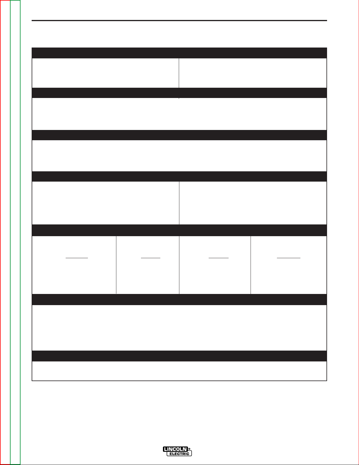
TECHNICAL SPECIFICATIONS – LN-23P
OPERATING ARC VOLTAGE
Constant Voltage (CV) 14-50VDC (90VDC Maximum OCV)
RATED CURRENT
250-350 Amps 60% Duty Cycle
(Depending on Gun Used)
WIRE SPEED RANGE
30-170 Inches Per Minute (IPM)
(1.18-6.70 mm)
RECOMMENDED ELECTRODE WIRE SIZES
A-2
.068” INNERSHIELD
” INNERSHIELD
.072
” INNERSHIELD
5/64
PHYSICAL DIMENSIONS
HEIGHT WIDTH DEPTH WEIGHT
20.5 Inches 9.0 Inches 19.0 Inches 27 lbs
(520.7 mm) (228.6 mm) (482.6mm) (12.3 kg)
TEMPERATURE RANGE
OPERATION: - 30oCo* to +40oC (- 22oF to +104oF)
o
STORAGE: - 40
C to +40oC (- 40oF to +104oF)
ENVIRONMENTAL RATING
EENNVVIIRROONNMMEENNTTAALL RRAATTIINNGG
Return to Section TOC Return to Section TOC Return to Section TOC Return to Section TOC
*At temperatures below 0°C, the gun cable may require a warm up operating time to improve flexibility.
Return to Master TOC Return to Master TOC Return to Master TOC Return to Master TOC
LN-23P
Page 9
SAFETY PRECAUTIONS
INSTALLATION
For K316L-2 or higher (8 pin connector)
A-3A-3
WARNING
ELECTRIC SHOCK can kill.
• Only qualified personnel should perform this installation, maintenance
and troubleshooting work.
• Turn off the input power at the fuse box before
working on other equipment connected to the
welding system at the disconnect switch or fuse
box before working on this equipment.
• Do not touch electrically hot parts.
------------------------------------------------------------------------
INPUT CABLE:
For K316L-1 (6 pin connector)
The standard 25 foot input cable between the LN-23P
and the power source (with a K350 Adapter Kit) consists of a six-conductor control cable and a 1/0 electrode cable. The control cable has lugged leads on the
power source end and a polarized plug on the wire
feeder end.
With the power source turned off, install the input
cable per the following instructions:
• Connect the end of the control cable with the lugged
leads to the K350 or K350-1 Adapter Kit. Connect
the electrode cable to the negative output stud on
the power source.
NOTE: If two LN-23Pʼs are connected to an Adapter
Kit, connect the feeder that will be used at the lowest voltage setting to Feeder “A” terminal strip in the
K350. If only one LN-23P is used, connect it to
Feeder “A” terminal strip.
• Connect the input control cable polarized plug into
the mating 6 pin receptacle on the rear of the control section of the LN-23P. Tighten the threaded
locking collar until the connector is completely seated.
• Unclip the rubber retaining strap that holds the wire
enclosure cover in place and remove the cover.
Push the wire drive section door latch towards the
rear of the LN-23P and open the door. Route the
electrode cable through the large rubber grommet
in the rear of the wire feed section and connect the
lug to the brass conductor block at the front of
motor-gearbox assembly using the bolt provided.
Attach the control cable strain relief hook to the
bracket on the frame of the LN-23P.
With the power source turned off, install the input
cable per the following instructions:
• The K316L-2 LN-23P can be connected directly to
any Lincoln power source that has CV output. and
Twist-Mate weld terminals (V350, V350-PIPE, CV305, etc..), using the control cable provided with the
machine.
• Connect the 14-pin connector and Twist-Mate plug of
the input cable assembly to the front of the welder.
• Unclip the rubber retaining strap that holds the wire
enclosure cover in place, and remove the cover.
Push the wire drive section door latch towards the
rear of the LN-23P and open the door. Route the
electrode cable through the large rubber grommet in
the rear of the wire feed section and connect the lug
to the brass conductor block at the front of the motor
gear box assembly using the bolt provided. Attach
the control cable strain relief hook to the bracket on
the frame of the LN-23P.
• Connect the 8-pin receptacle to the LN-23P located
on the back underside of the control box.
WORK CABLE AND REMOTE VOLTAGE
SENSING WORK LEAD
• Connect a work cable of sufficient size and length,
per the following table, between the proper output
stud on the power source and the work. Be sure the
connection to the work makes tight metal to metal
contact.
Electrode Work Copper Copper
Cable Cable Electrode Work Cable
Length Length Cable Size Size
0-25 ft. 0-75 ft. 1/0 1/0
0-25 76-125 1/0 2/0
26-75 26-75 2/0 2/0
26-75 76-125 2/0 4/0
76-100 76-125 3/0 4/0
Above cable sizes are based on a maximum voltage drop of
4.3 volts in the combined lengths of electrode and work cable
at 350 amps.
•
Connect a 12 AWG or larger rubber covered flexible
lead physically suitable for the installation to the
voltage sensing work lead (#21) coming from the
Adapter Kit. For convenience, wrap this voltage
sensing lead around the work lead and tape in
place. Connect it directly to the work or to the work
cable connection . This lead supplies voltage to the
voltmeter as well as power to the LN-23P control
circuitry and drive motor.
Return to Section TOC Return to Section TOC Return to Section TOC Return to Section TOC
Return to Master TOC Return to Master TOC Return to Master TOC Return to Master TOC
LN-23P
Page 10

INSTALLATION
WIRE DRIVE ROLLS AND GUIDE TUBES
The LN-23P is shipped with the proper drive rolls and
guide tubes factory installed. Do not adjust the idle roll
tension adjusting screw. If the idle roll tension must be
relieved temporarily, see “A” and “B” of Maintenance
Section.
OPTIONAL FEATURES INSTALLATION
INNERSHIELD GUN AND CABLE
•
Unclip the rubber retaining strap that holds the wire
enclosure cover in place and remove the cover.
•
Push the wire drive section door latch towards the
rear of LN-23P and open door.
•
Loosen the gun locking set screw in the conductor
block on the front of the gear box with a 3/16 hex
Allen wrench.
•
Lay the cable out straight. Insert the connector on
the conductor cable thru the large grommet in the
front of the wire drive section and into the brass
block on the front of the gear box. Make sure it is all
the way in and tighten the locking set screw with a
3/16 hex Allen wrench. Keep this connection clean
and bright.
•
Connect the 3 pin gun trigger connector to the lower
receptacle.
•
If the gun cable being used has a reduced speed
switch, connect the 4 pin reduced speed switch
connector to the upper receptacle. If the reduced
speed switch is not used, install the protective cap
on the upper receptacle.
A-4A-4
•
DC-600 (below code 10500): Attach the triangular
mounting plate to the shock mounted plate of the
Adapter with three of the #10 self-tapping screws
provided. Attach the triangular plate to the side of
the DC-600 adjacent to the control terminal strips
using two roof screws and one front panel screw.
Connect the Adapter control cable to the DC-600
terminal strips power the proper connection diagram.
•
Other Power Sources: Mount the Adapter Kit to the
side of the power source or some convenient location so its control cable can be connected to the
power source terminal strip. Use the shock mounted mounting plate as a template to locate the four
5/32" diameter holes that must be drilled in the case
side. (Use caution not to drill into or get chips into
any internal components.) Mount the Adapter Kit
with four of the #10 self-tapping screws provided.
Connect the Adapter control cable to power source
terminal strips per the proper connection diagram.
K350-1 ADAPTER KIT - Turn off power source and all
power to the power source.
Used to connect an LN-23P (K316L-1) to a Lincoln
power source that has a 14 pin control connector.
•
Mount the Adapter Kit to the side of the power
source or some convenient location so its control
cable can be connected to the power source terminal strip. See the mounting instructions form the
K350
•
Connect the Adapter control cable to 14 pin connector on the power source per the proper connection diagram.
•
Connect a 12 AWG or larger rubber covered flexible
lead physically suitable for the installation to the
voltage sensing work lead (#21) coming from the
LN23P control cable connector. For convenience,
wrap this voltage sensing lead around the work lead
and tape in place. Connect it directly to the work or
to the work cable connection
Return to Section TOC Return to Section TOC Return to Section TOC Return to Section TOC
K-350 ADAPTER KIT– Turn off power source and all
power to the power source.
•
SAM-400 Engine Welders: Attach the shock mounted mounting plate to the front of the SAM electrical
component panel to left of the relay case with 4 of
the #10 self-tapping screws provided. Older models
require the drilling of 4 5/32 dia. holes into the
panel. Connect the adapter control cable to the
SAM terminal strips per the proper connection diagram.
Return to Master TOC Return to Master TOC Return to Master TOC Return to Master TOC
K-276 ENCLOSED 50lb.WIRE REEL SUPPORT
Installation and loading instructions (M-13153) are
supplied with the kit.
------------------------------------------------------------------------
LN-23P
Page 11

ACCESSORIES
A-5A-5
POWER SOURCE
One or two LN-23Pʼs can be connected to a DC power source (constant voltage) with a K-350 or K350-1 Adapter
Kit. If two LN-23Pʼs are connected, they can be set for different procedures but only one can be used at a time.
LN-23P/ Power Source Combinations
1. Classic II, Classic III, Classic IIID, or SA-250 with K350-1 Adapter Kit and K623-1 Wire Feed Module.
2. Commander 300, Commander 400 or Commander 500 with K350-1 Adapter Kit.
3. Ranger 250 , Ranger 275, or Ranger 305G with K350-1 Adapter Kit.
4. CV-300, CV305, CV-400, DC-400, DC-600, DC655 or V300, V350 Pro, V450 Pro with K350-1 Adapter Kit.
NOTE: The K350 must be used on power sources with terminal strip connections only.
K316L-2 may not require a K350-1 adapter if the power source has a Lincoln 14 pin connector.
5. SAE-400 or SAE-400 Weld ʼN Air with K316L-2, K385-1, 2 CV Adapter & K350, K2379-1 Adapter Kit.
NOTE: Only allows for one LN-23P feeder.
6. SAE-400 with a K385-1 and a K350 Adapter.
Gun will always be HOT when SAE-400 is running.
NOTE: K350 will have to be powered from 120VAC receptacle (customer responsibility).
No remote control of weld voltage from LN-23P
Gun will always be HOT when SAE -400 is running
7. LN-23P (K316L-2) used with V350-Pipe does not require a K350-1 Adapter.
Power source connection diagrams:
M17323
M14272
S25869
S25149
Return to Section TOC Return to Section TOC Return to Section TOC Return to Section TOC
Return to Master TOC Return to Master TOC Return to Master TOC Return to Master TOC
LN-23P
Page 12

NOTES
A-6A-6
Return to Section TOC Return to Section TOC Return to Section TOC Return to Section TOC
Return to Master TOC Return to Master TOC Return to Master TOC Return to Master TOC
LN-23P
Page 13

TABLE OF CONTENTS
- OPERATION SECTION -
Operation . . . . . . . . . . . . . . . . . . . . . . . . . . . . . . . . . . . . . . . . . . . . . . . . . . . Section B
Safety Precautions . . . . . . . . . . . . . . . . . . . . . . . . . . . . . . . . . . . . . . . . . . B-2
Product Description . . . . . . . . . . . . . . . . . . . . . . . . . . . . . . . . . . . . . . . . . B-2
Loading the Wire Reel . . . . . . . . . . . . . . . . . . . . . . . . . . . . . . . . . . . . . . . B-2
Drive Roll Pressure . . . . . . . . . . . . . . . . . . . . . . . . . . . . . . . . . . . . . . . . . B-3
Making the Weld . . . . . . . . . . . . . . . . . . . . . . . . . . . . . . . . . . . . . . . . . . . . B-3
Section BSection B
Return to Master TOC Return to Master TOC Return to Master TOC Return to Master TOC
LN-23P
Page 14

OPERATION
B-2B-2
SAFETY PRECAUTIONS
WARNING
ELECTRIC SHOCK can kill.
• Do not touch electrically live parts
such as output terminals or internal
wiring.
• When inching with gun trigger, electrode and
drive mechanism are “hot” to work and ground
and could remain energized several seconds
after the gun trigger is released.
• Turn OFF input power at welding power source
before installation or changing drive roll and/or
guide tubes.
• Welding power source must be connected to
system ground per the National Electrical Code
or any applicable local codes.
• Only qualified personnel should perform this
installation.
------------------------------------------------------------------------
PRODUCT DESCRIPTION
The K316L-[ ] / LN-23P is an arc voltage powered,
lightweight, portable wire feed unit which includes calibrated wire speed control, voltage control, wire drive
with enclosed 14 lb. wire reel, analog voltmeter and
various input control and electrode cable lengths.
The LN-23P was designed specifically for Innershield
pipe welding, but, with the proper electrode, can be utilized for general purpose welding.
The feeder is designed for welding with 14 pound coils
of .068 and 5/64 Innershield self-shielding electrodes
using a constant voltage type DC power Source. When
shipped, it is internally connected for welding with electrode negative polarity (DC–). Depending upon which
gun and cable is used, its rating is either 350 amps or
250 amps at 60% duty cycle.
The wire speed control has a calibrated dial plate with
a range of 30 to 170 inches per minute which allows
quick and easy setting of the procedure wire feed
speed. The wire speed is not affected by changes in
the arc voltage setting even though the wire feed circuit
is powered by arc voltage. A two-position switch,
mounted on the gun provides a reduced speed circuit.
This allows selection of either the preset wire speed or
83% of the preset speed.
A low voltage gun trigger circuit turns both the power
source output and wire feed on and off. The gun trigger
circuit is interlocked by a weld current sensing reed
switch so that while welding, the gun trigger switch
does not have to be held closed. The welding process
is stopped by pulling the gun away from the work. The
electrode remains cold until the gun trigger is operated
again.
The LN-23Pvoltage control is used to adjust the power
source output. Also included is an analog voltmeter
which allows easy setting of the arc voltage at the LN23P once the arc is established.
LOADING THE WIRE REEL
• Lay the LN-23P flat with the wire reel cover up,
unclip the rubber retaining strap, and remove the
cover.
• Remove the center clamping nut and the cover
plate from the wire reel.
• Unpack the 14-pound coil of wire. Be sure not to
bend the side tangs of the coil liner and straighten
any tangs that may have been bent.
• Place the coil on the wire reel so the coil will unwind
when it rotates in a clockwise direction.
• Remove the start end of the coil from its holding slot
in the coil liner, cut off the bent end, straighten the
first few inches and thread it through the wire feed
conduit connected to the wire enclosure until several inches of electrode are exposed. Be careful not to
release the electrode until it is through the wire feed
conduit; otherwise, it will unwind and tangle.
• Be sure all the lower tangs of the coil liner are flush
against the back half of the wire reel and that none
of the upper tangs are bent in against the coil.
• Replace the reel cover plate and the center clamping nut.
• Replace the cover of the wire reel enclosure and
clip the retaining strap in place.
• Pull about 2 feet of the exposed end of the electrode through the wire feed conduit. Slide the insulator all the way up on the wire feed conduit.
Make a single, free loop in the electrode and feed
the end into the section of wire feed conduit connected to the gearbox. Press the gun trigger and
push the electrode into the drive rolls. Release the
electrode as soon as it is picked up by the drive
rolls. Continue feeding electrode until the excess
length is fed through the drive rolls. Watch the single loop and guide it if necessary to make certain it
untwists without kinking. Do not feed electrode
through the gun cable at this time. Slide the insulator down on wire feed conduit until it slips over section of conduit connected to gearbox.
• Set the unit upright on floor, straighten the gun
cable, press the gun trigger, and feed electrode
through the gun and cable assembly.
Return to Section TOC Return to Section TOC Return to Section TOC Return to Section TOC
Return to Master TOC Return to Master TOC Return to Master TOC Return to Master TOC
LN-23P
Page 15

OPERATION
B-3B-3
DRIVE ROLL PRESSURE
The drive roll pressure is pre-set at the factory for
proper feeding. If the idle roll tension must be relieved
temporarily, see the Maintenance Section for proper
adjustment procedure.
ADJUSTING WIRE FEED SPEED AND
VOLTAGE
Set the wire feed as specified in the procedures using
the calibrated dial on the back of the LN-23P control
box. When the reduced wire speed switch (mounted
on the gun handle) is in Position No. 1, the wire feed
speed will be that which is indicated on the dial. In
Position No. 2, the wire feed speed will be 83% of the
figure indicated on the dial.
Set the voltage by adjusting the voltage control while
welding until the voltage specified in the procedures is
indicated on the meter. The meter reading with the
power source on but not welding is the open circuit
voltage. With some power sources, this voltage may
be significantly higher than welding voltage.
When establishing initial procedures, start with the
voltage control set near minimum. Strike an arc on
scrap steel. If the electrode gets hot but the arc fails to
start, increase the voltage settings until the arc can be
established.
NEVER set the power source open circuit voltage
higher than 50
when the voltage is higher than 50
(1)
volts. The LN-23P will not feed wire
(1)
volts.
convenient for the particular application, and retighten
the screw.
When welding, set the wire feeder on the floor or hang
it near the work area as convenient. Place the LN-23P
to minimize the amount of spatter falling onto it.
Always avoid sharp bends and keep the gun cable
as straight as practical.
Be sure the electrode cable, work cable, and control
lead are connected and the power source is on.
Press the gun trigger to feed the electrode out of the
gun. Use a visible stickout equal to the electrical stickout specified in the procedures for the wire being used.
Position the gun with the wire just off or lightly touching the work. Press the gun trigger to start the arc.
Once the arc is established, the gun trigger can be
released while welding. The gun trigger interlock circuit
automatically keeps the welding process on. At the end
of the weld, pull the gun away from the work.
When not welding, always store the gun in the insulated tube on the front of wire feeder.
While welding with one feeder of a two-feeder installation the electrode of the second feeder is “HOT”. Only
one feeder at a time can be used for welding. Do not
press the gun trigger of the idle feeder while the other
feeder is being used since this can shut down the feeder being used for welding.
Return to Section TOC Return to Section TOC Return to Section TOC Return to Section TOC
When using the CV Converter or the DC-600 and inching wire (not welding) at open circuit voltages below 20
volts or above 25 volts, feeding may be unsteady or
the wire speed may vary from that set on the dial. This
condition does not exist while welding. Minimum
usable arc voltage is 14 volts.
NOTE: For improved readability of the voltmeter in
some applications, the voltmeter guard may be
installed rotated end for end. This will result in the protective bars crossing the meter face in a different location.
MAKING THE WELD
Be sure the proper contact tip for either .068" or 5/64"
wire, as appropriate, is in the gun. The thread protector should cover the external threads on the nozzle.
Loosen the insulated socket head screw on the side of
the gun, rotate the gun nozzle to the position most
(1)
45 volts on DC-600.
Return to Master TOC Return to Master TOC Return to Master TOC Return to Master TOC
LN-23P
Page 16

NOTES
B-4B-4
Return to Section TOC Return to Section TOC Return to Section TOC Return to Section TOC
Return to Master TOC Return to Master TOC Return to Master TOC Return to Master TOC
LN-23P
Page 17

TABLE OF CONTENTS
- ACCESSORIES SECTION -
Accessories . . . . . . . . . . . . . . . . . . . . . . . . . . . . . . . . . . . . . . . . . . . . . . . . . . Section C
LN-23P Gun and Cable Assemblies Chart . . . . . . . . . . . . . . . . . . . . . . . . C-2
Optional Accessories . . . . . . . . . . . . . . . . . . . . . . . . . . . . . . . . . . . . . . . . C-2
K350 Adapter Kit . . . . . . . . . . . . . . . . . . . . . . . . . . . . . . . . . . . . . . . . C-2
K350-1 Adapter Kit . . . . . . . . . . . . . . . . . . . . . . . . . . . . . . . . . . . . . . C-2
K276 Enclosed Wire Reel Support . . . . . . . . . . . . . . . . . . . . . . . . . . C-2
Section CSection C
Return to Master TOC Return to Master TOC Return to Master TOC Return to Master TOC
LN-23P
Page 18

ACCESSORIES
OPTIONAL EQUIPMENT
GUN AND CABLE ASSEMBLIES
Type K-355-10* K-345-10* K-264-8 K-361-10 K-406*
C-2C-2
Length: 10 feet 10 feet 8 feet 10 feet Linconditioner Gun 10 ft.
Rated Welding
Current: 250 Amps 350 Amps 250 Amps 350 Amps 350 Amps
Duty Cycle 60% 60% 60% 60% 60%
Electrode Sizes .068, .072, 5/64 .068, .072, 5/64 068, .072, 5/64 068, .072, 5/64 068, .072, 5/64
Reduced Speed
Switch Std. Std. None None Std.
Sizes 5/64 5/64 5/64 5/64 5/64
Nozzle Angle 90E 90E 62E 62E 68E
Weight 7.0 lbs. 89.3 lbs. 5.2 lbs. 7.5 lbs. 16.0 lbs.
* Recommended for pipe welding applications.
All guns include one each .068/.072 tip, 5/64 tip, and a thread protector**. The K-264-8 also includes an insulated guide for
3/4" to 1-1/2" stickout. The K-361-10 also includes an insulated guide for 2" stickout.** The K-406 includes an insulated
guide for 2" to 1" stickout, but no thread protector.
(15 ft. Exhaust Hose)
K350 ADAPTER KIT
K-276 ENCLOSED WIRE REEL SUPPORT
Required when using the LN-23P on any constant
voltage power source. Either one or two LN-23Pʼs can
be connected to the Adapter. If two LN-23Pʼs are connected, they can be set for different procedures. The
Adapter circuit is interlocked so only one LN-23P can
Bolts to the LN-23P frame for feeding wire from standard 50 lb. Innershield coils. Includes enclosure and
door to keep the dirt out; also includes wire reel brake
assembly.
be used at a time.
Return to Section TOC Return to Section TOC Return to Section TOC Return to Section TOC
K350-1Adapter Kit
The K350-1 is similar to the K350 but has a 14 pin
connector on the end of the control cable that will
interface with any Lincoln power source that utilizes a
14 pin connector for control.
Note: A K350 Adapter Kit is not required when con-
necting a LN-23P / K316l-2 (8pin connector) to
a V350-Pipe, V350PRO or V450PRO.
Return to Master TOC Return to Master TOC Return to Master TOC Return to Master TOC
LN-23P
Page 19

TABLE OF CONTENTS
- MAINTENANCE SECTION -
Maintenance . . . . . . . . . . . . . . . . . . . . . . . . . . . . . . . . . . . . . . . . . . . . . . . . . Section D
Safety Precautions . . . . . . . . . . . . . . . . . . . . . . . . . . . . . . . . . . . . . . . . . . D-2
Replacing or Reeversing Drive Rolls . . . . . . . . . . . . . . . . . . . . . . . . . . . . D-2
Removing Idle Roll Assembly . . . . . . . . . . . . . . . . . . . . . . . . . . . . . . . . . . D-2
Gun and Cable Maintenance . . . . . . . . . . . . . . . . . . . . . . . . . . . . . . . . . . D-2
Wire Drive Assembly Maintenance . . . . . . . . . . . . . . . . . . . . . . . . . . . . . D-2
Circuit Protection . . . . . . . . . . . . . . . . . . . . . . . . . . . . . . . . . . . . . . . . . . . D-3
Nameplates . . . . . . . . . . . . . . . . . . . . . . . . . . . . . . . . . . . . . . . . . . . . . . . D-3
Section DSection D
Return to Master TOC Return to Master TOC Return to Master TOC Return to Master TOC
LN-23P
Page 20

MAINTENANCE
23
614
5
IDLE ROLL TENSION
ADJUSTING SCREW
D-2D-2
SAFETY PRECAUTIONS
WARNING
Have qualified personnel do the maintenance
work. Turn the engine off before working inside
the machine. In s om e cas e s , it may be
necessary to remove safety guards to perform
required maintenance. Remove guards only
when necessary and replace them when the
maintenance requiring t h e i r removal i s
complete. Always use the greatest care when
working near moving parts.
-----------------------------------------------------------------------
ELECTRIC SHOCK can kill.
• Do not touch electrically live parts or
electrode with skin or wet clothing.
• Insulate yo u r s e l f from work an d
ground
• Always wear dry insulating gloves.
------------------------------------------------------------------------
See add ition al w arnin g in f ormat ion
throughout this operatorʼs manual and
the Engine manual as well.
-----------------------------------------------------------
REPLACING OR REVERSING DRIVE ROLLS (See
Figure D.1)
GUN AND CABLE MAINTENANCE
Remove spatter from tip after each ten minutes of arc
time or as required.
Replace worn contact tips and thread protectors as
required.
Replace worn spring liners in nozzles. The life of the
spring can be doubled by rotating it 180°.
Clean cables after using approximately 300 pounds of
electrode. Remove the cable from the wire feeder and
lay it out straight on the floor. Remove the contact nozzle tip from the gun. Using an air hose and only partial
pressure, gently blow out the cable from the gun end.
(Too much pressure at the start will cause the dirt to
form a plug.) Flex the cable over its entire length and
again blow out the cable. Repeat this procedure until
no further dirt comes out.
Before any gun is disassembled, remove unit from the
wire feeder or shut off the power source.
FIGUIRE D.1
Loosen idle roll tension screw (Item 1) to release pressure between idle roll and drive rolls.
Remove hex head screw (Item 2) with a 1/2" wrench
and remove the drive roll clamping collar (Item 3).
Remove drive rolls from shaft.
Wipe the drive roll surfaces clean. Then install new
drive rolls. If reversing drive rolls, turn drive rolls over so
unworn teeth face each other.
Replace clamping collar and hex head screw.
Tighten the idle roll tension screw until it bottoms and
then back it out two complete turns. If feeding problems
persist, do not increase the tension. check for other
issues such as the wire spool binding or a dirty or damaged gun cable
REMOVING IDLE ROLL ASSEMBLY
Remove the idle roll tension screw (Item 1), tension
spring retainer (Item 4), and tension spring (Item 5).
Pivot the idle roll assembly away from the gearbox and
lift it off the pivot pin (Item 6).
WIRE DRIVE ASSEMBLY MAINTENANCE
Every 500 pounds of electrode, the drive roll section
should be inspected and cleaned out if necessary. Do
not use a solvent for cleaning the idle roll as it may
wash lubricant out of the bearing.
Replace drive rolls as required. Drive rolls should be
worn on both sides before replacing. See “A” of this
section.
Check the motor brushes every six months. Replace if
they are less than 1/4" long.
Return to Section TOC Return to Section TOC Return to Section TOC Return to Section TOC
To re-assemble, replace idle roll assembly, tension
spring, retainer, and tension screw. Adjust the tension
screw as described above.
Return to Master TOC Return to Master TOC Return to Master TOC Return to Master TOC
Every year examine the gear box and paint the gear
teeth with moly-disulfide filled grease.
LN-23P
Page 21

MAINTENANCE
D-3D-3
CIRCUIT PROTECTION
Circuit Breaker – The 3.5 amp circuit breaker located
on the rear of the unit normally trips only when an overload occurs because of excessive loading in the wire
feed cable or a defective motor or control components.
After allowing a few minutes for cooling, push the reset
button and weld. If it trips again, be sure the gun cable
is not being excessively bent, is clean, and is the proper size for the wire diameter being fed. If it still trips,
look for a defective electrical component.
NAMEPLATES
Whenever routine maintenance is performed on this
machine — or at least yearly — inspect all nameplates
and labels for legibility. Replace those which are no
longer clear. Refer to the parts list for the replacement
item number.
Return to Section TOC Return to Section TOC Return to Section TOC Return to Section TOC
Return to Master TOC Return to Master TOC Return to Master TOC Return to Master TOC
LN-23P
Page 22

NOTES
D-4D-4
Return to Section TOC Return to Section TOC Return to Section TOC Return to Section TOC
Return to Master TOC Return to Master TOC Return to Master TOC Return to Master TOC
LN-23P
Page 23

TABLE OF CONTENTS
+
VOLTMETER
WIRE SPEED CONTROL
REDUCED SPEED CONTROL
GUN TRIGGER SWITCH
REED SWITCH ACTIVATED
GUN CONDUCTOR BLOCK
WIRE FEED MOTOR
BY WELDING CURRENT
VOLTAGE CONTROL
LN-23P
CONTROL
P.C. BOARD
3.5 A CIRCUIT
BREAKER
567
R12
R75
535
535
A
B
C
D
539
647
647
WORK
604
602
604
604
21
77
75
76
521
602
604
WORK (+)
ELECTRODE (-)
6 PIN CONNECTOR
8 PIN CONNECTOR
602
TP2
R76
1
1 23456
42536
541
641
BLACK
WHITE
642
67
521
567A
567
601
75
76
77
642
521
644
10KΩ, 4 W
82V, 12J
100Ω, 1 W
10KΩ, 4 W
A
B
C
GECDHF
DCBAF E
- THEORY OF OPERATION SECTION -
Theory of Operation . . . . . . . . . . . . . . . . . . . . . . . . . . . . . . . . . . . . . . . . . . . Section E
General Description . . . . . . . . . . . . . . . . . . . . . . . . . . . . . . . . . . . . . . . . . E-2
Input Power Circuit . . . . . . . . . . . . . . . . . . . . . . . . . . . . . . . . . . . . . . E-2
Control Circuit Operation . . . . . . . . . . . . . . . . . . . . . . . . . . . . . . . . . . . . . E-3
Volts and Speed Control Circuits . . . . . . . . . . . . . . . . . . . . . . . . . . . E-3
Trigger and Interlock Circuits . . . . . . . . . . . . . . . . . . . . . . . . . . . . . . . E-3
Optional Circuits . . . . . . . . . . . . . . . . . . . . . . . . . . . . . . . . . . . . . . . . . . . . E-4
FIGURE E.1 GENERAL DIAGRAM
Section ESection E
Return to Master TOC Return to Master TOC Return to Master TOC Return to Master TOC
LN-23P
Page 24

THEORY OF OPERATION
+
VOLTMETER
WIRE SPEED CONTROL
REDUCED SPEED CONTROL
GUN TRIGGER SWITCH
REED SWITCH ACTIVATED
GUN CONDUCTOR BLOCK
WIRE FEED MOTOR
BY WELDING CURRENT
VOLTAGE CONTROL
LN-23P
CONTROL
P.C. BOARD
3.5 A CIRCUIT
BREAKER
567
R12
R75
535
535
A
B
C
D
539
647
647
WORK
604
602
604
604
21
77
75
76
521
602
604
WORK (+)
ELECTRODE (-)
6 PIN CONNECTOR
8 PIN CONNECTOR
602
TP2
R76
1
1 23456
42536
541
641
BLACK
WHITE
642
67
521
567A
567
601
75
76
77
642
521
10KΩ, 4 W
82V, 12J
100Ω, 1 W
10KΩ, 4 W
A
B
C
G EC DH F
DCBAF E
644
FIGURE E.2 – INPUT POWER CIRCUIT.
E-2E-2
Return to Section TOC Return to Section TOC Return to Section TOC Return to Section TOC
GENERAL DESCRIPTION
The LN-23P is an Arc Voltage powered, lightweight,
portable wire feed unit which includes calibrated wire
speed control, voltage control, and wire drive with an
enclosed 14 lb. wire reel, analog voltmeter and various
input control and electrode cables.
The LN-23P was designed specifically for Innershield
pipe welding, but, with the proper electrode, can be utilized for general purpose welding. The machine is
internallly connected for negative polarity (DC-). It will
feed .068 or 5/64 Innershield wire using one of several
different gun cable assemblies. It is designed to be
used with any Lincoln constant voltage (CV) power
source that is suited to the operating range of those
wires.
Other features include a Wire Speed Reduction Switch
and a trigger interlock circuit which will be discussed in
more detail.
NOTE: Unshaded areas of block logic diagrams are the subject of discussion.
Return to Master TOC Return to Master TOC Return to Master TOC Return to Master TOC
INPUT POWER CIRCUIT
The DC arc voltage from the power source is applied
to the LN-23P by way of the electrode cable (-)and the
LN-23P
Work Sensing Lead (+). . Typically the work connection
is through the control cable of the K350 Adapter. If no
adapter is used the connection is through the power
source. The voltage is then coupled to the Control
Board at lead 67 and 521.
The electrode circuit (lead #67) is routed out of the
board (lead #567) to the 3.5 amp circuit breaker and
back to the board (lead 567A). The Circuit Breaker
provides protection for the board from motor overload.
Leads 567 and 521 are routed through the Control
Board to the Voltmeter. See Figure E.2.
Page 25

THEORY OF OPERATION
+
VOLTMETER
WIRE SPEED CONTROL
REDUCED SPEED CONTROL
GUN TRIGGER SWITCH
REED SWITCH ACTIVATED
GUN CONDUCTOR BLOCK
WIRE FEED MOTOR
BY WELDING CURRENT
VOLTAGE CONTROL
LN-23P
CONTROL
P.C. BOARD
3.5 A CIRCUIT
BREAKER
567
R12
R75
535
535
A
B
C
D
539
647
647
WORK
604
602
604
604
21
77
75
76
521
602
604
WORK (+)
ELECTRODE (-)
6 PIN CONNECTOR
8 PIN CONNECTOR
602
TP2
R76
1
123456
42536
541
641
BLACK
WHITE
642
67
521
567A
567
601
75
76
77
642
521
10KΩ, 4 W
82V, 12J
100Ω, 1 W
10KΩ, 4 W
A
B
C
GECDHF
DCBAF E
644
FIGURE E.3 – CONTROL CIRCUITS.
E-3E-3
Return to Section TOC Return to Section TOC Return to Section TOC Return to Section TOC
Return to Master TOC Return to Master TOC Return to Master TOC Return to Master TOC
CONTROL CIRCUIT OPERATION
VOLTS AND SPEED CONTROL CIRCUITS
The Volta ge Control is connected directly to th e
K350 Adapter or the power source (if no adapter is
required) by leads 75, 76 & 77. It can be adjusted
while welding to provide the voltage called for by the
weld procedure.
The wire feed speed is controlled by signals to the
Control B o a r d from t h e Speed Co n t r o l and t h e
Reduced Speed Switch. The Wire Speed Control is
calibrated and can be preset to the desired value.
The speed will remain at the set value regardless of
arc voltage as long as the Reduced Speed Switch
is in Position 1 (open).
When the Reduced Speed Switch is in Position 2
(closed) the speed will be reduced to 83% of the set
speed. This switch is to facilitate welding if the root
opening changes or to reduce “sagging” of the weld
metal as the operator approaches the bottom of a
pipe joint. The switch may be changed to either
NOTE: Unshaded areas of block logic diagrams are the subject of discussion.
position while welding as needed without stopping
or breaking the arc.
LN-23P
TRIGGER AND INTERLOCK CIRCUIT
The gun trigger (leads 602 & 604) is connected to the
24VAC circuit from the K350 Ada pter, or the low
voltage output control circuit (#2 & #4) of the power
source if no K350 is required.
Once the trigger is closed the wire starts feeding.
When the arc is estblished, the reed switch closes
(leads 647 & 604) and the trigger is bypassed or
“interlocked”. This feature allows the operator to
release the trigger once the weld has begun to help
eliminate fatigue.
The reed switch is a magnetically operated device that
is mounted on a bracket above the block where the
gun connect s to the fe eder. It resp onds to the
magnetic field that is presnt due to the weld current
flowing through the gun cable.
To stop welding, the operator must physically pull the
gun away from the weld, thus stopping current flow
and releasing the reed switch. See Figure E.3.
Page 26

THEORY OF OPERATION
FIGURE E.4 – OPTIONAL CIRCUITS.
E-4E-4
Return to Section TOC Return to Section TOC Return to Section TOC Return to Section TOC
OPTIONAL CIRCUITS
K350 / K350-1ADAPTER KITS
The K350 Adapter kits are used to interface one or
two LN-23P feeders to a Lincoln CV power source.
Figure E.4 shows a typical two feeder connection
using a K350-1. If only one feeder is used it must
be connected to the “Feeder A” terminal strip.
NOTE: Many of the newer power sources allow a
single feeder to be connected without using
an adapter kit. See the connection diagrams
in Section G.
NOTE: Unshaded areas of block logic diagrams are the subject of discussion.
Return to Master TOC Return to Master TOC Return to Master TOC Return to Master TOC
WARNING
In a two feeder system, both guns will be ʻHOTʼ
when either gun is triggered
In a two feeder system, triggering the second gun
while one is welding may cause the feeder in use
to shut down.
LN-23P
Page 27

THEORY OF OPERATION
8 CONDUCTOR CONTROL CABLE
C(75)
B(76)
A(75)
4
31
32
2A
2B
GND
M17514
12-01
1
3
4
5
6
2
6
4 2
1
5
*
RELAY P.C. BOARD
3
1CR
21
521
609
608
610
604B
607
75
B
A
608
75A
75B
4
76A
76B
602
604
757677
521
602
604
757677
521
602
2CR
B
A
609
521B
521A
2B
2A
31
32
4
77
76
75
21
607
606
605
A
A
A
A
A
A
A
A
A
(J)
(A)
(D)
(C)
(H)
A
A
(E)
(F)
(G)
(I)
(K)
(B)
31
32
4
2
77
76
75
GND
2B
2 1
4
7
5
8
3
6
9
4
610
3
2
1
6
5
4
789
604A
76
2A
INDICATES CONNECTOR
CAVITY NUMBER
A.N.S.I. ELECTRICAL SYMBOLS PER E1537
COLOR LEGEND
R=RED
B=BLACK
8 CONDUCTOR CONTROL CABLE
"A" WIRE FEEDER "B" WIRE FEEDER
TERMINAL STRIP
TERMINAL STRIP
24V. CONTROL TRANSFORMER
2C
21
521
R
RBB
606
605
ICR & 2CR - 3 PDT, 24V.D.C.
AMPHENOL
SENSE LEAD
FIGURE E.5 K350-1 DIAGRAM
E-5E-5
K350 / K350-1ADAPTER KITS (cont.)
The wiring diagram in Figure E.5 shows the internal
Return to Section TOC Return to Section TOC Return to Section TOC Return to Section TOC
connections that allow the voltage control, the welder
output (contactor) control and the Work Sense Lead
(#21) to be switched from one feeder to the other.
The Relay Board and the two relays (1CR & 2CR)
connect the feeder that has been triggered to the
power source through the control cables. See the
K350 Machine Schematic in Section G for a better
understanding of the relay logic.
Return to Master TOC Return to Master TOC Return to Master TOC Return to Master TOC
FIGURE E.5.a
K350 Control Cable - for use with
power sources that do not have a
14 pin Amphenol connector
The 24 volt control transformer provides power for
the Relay Board and the relays. It is also the low
voltage trigger circuit supply for the LN-23P.
The K350 is basically the same as the K350-1
except the Control Cable to the power source has
leads with terminals. (Figure E.5.a). It is designed to
be used with power sources that have a terminal
strip for the wire feeder connection rather than a 14
pin connector.
NOTE: Unshaded areas of block logic diagrams are the subject of discussion.
LN-23P
Page 28

NOTES
E-6E-6
Return to Section TOC Return to Section TOC Return to Section TOC Return to Section TOC
Return to Master TOC Return to Master TOC Return to Master TOC Return to Master TOC
LN-23P
Page 29

Section F-1 Section F-1
TABLE OF CONTENTS
-TROUBLESHOOTING AND REPAIR-
Troubleshooting and Repair . . . . . . . . . . . . . . . . . . . . . . . . . . . . . . . . . . . . Section F
How to Use Troubleshooting Guide . . . . . . . . . . . . . . . . . . . . . . . . . . . . . F-2
PC Board Troubleshooting Procedures . . . . . . . . . . . . . . . . . . . . . . . . . . F-3
Troubleshooting Guide . . . . . . . . . . . . . . . . . . . . . . . . . . . . . . . . . . . . . . . F-4
Test Procedures . . . . . . . . . . . . . . . . . . . . . . . . . . . . . . . . . . . . . . . . . . . . . . F-7
Wire Feeder Test . . . . . . . . . . . . . . . . . . . . . . . . . . . . . . . . . . . . . . . . F-7
Gun Test . . . . . . . . . . . . . . . . . . . . . . . . . . . . . . . . . . . . . . . . . . . . . . F-9
Feed Head Test . . . . . . . . . . . . . . . . . . . . . . . . . . . . . . . . . . . . . . . . . F-11
Potentiometer Test . . . . . . . . . . . . . . . . . . . . . . . . . . . . . . . . . . . . . . . F-13
K350 (-1) Adapter Test . . . . . . . . . . . . . . . . . . . . . . . . . . . . . . . . . . . F-15
Calibration Check . . . . . . . . . . . . . . . . . . . . . . . . . . . . . . . . . . . . . . . F-18
WARNING
ELECTRIC SHOCK can kill.
• Never work on the inside of the machine without removing the
input power. You can receive a life threatening electrical shock if
you f ail to do this. Only qualified tech nicians should p erform
insta l l a t i on, ma i n t e nance, an d troub l e s h o oting wo r k on t h e
machine.
Return to Master TOC Return to Master TOC Return to Master TOC Return to Master TOC
LN-23P
Page 30

F-2 F-2
TROUBLESHOOTING AND REPAIR
How To Use Troubleshooting Guide
WARNING
Service and Repair should only be performed by Lincoln Electric Factory Trained
Personnel. Unauthorized repairs performed on this equipment may result in danger
to the technician and machine operator and will invalidate your factory warranty. For
your safety and to avoid Electrical Shock, please observe all safety notes and
precautions detailed throughout this manual.
This Troubleshooting Guide is provided to help
you lo c a t e a n d r e p a i r p o ssible machine
malf u n c t i o n s. Simply fo l l o w th e three step
procedure below.
Step 1. LOCATE PROBLEM (SYMPTOM).
Lo ok unde r t he colu mn lab eled "PRO BLEM "
(SYMPTOMS). This column describes possible
symptoms that the machine may exhibit. Find
the listing that best describes the symptom that
the m a chine i s exhibiting . Symptoms a r e
gr o uped into thre e main c atego r ies: Outp u t
Problems, Function Problems and LED Function
problems.
Step 2. PERFORM EXTERNAL TESTS. The
second column, labeled "POSSIBLE AREAS OF
MISA D J U S T M E NT(S)", l i s t s the o bvious
external possibilities that may contribute to the
machine symptom. Perform these tests/checks
in the order listed. In general, these tests can be
con-ducted without r emo ving the case wrap-
around cover.
Step 3. PERFORM COMPONENT TESTS. The
last column, labeled "Recommended Course of
Action" lists the most likely components that may
have failed in your machine. It also specifies the
appropriate test procedure to verify that the subject component is either good or bad. If there are
a number of poss ible components, check the
components in the order listed to eliminate one
possibility at a time until you locate the cause of
your problem.
All of the referenced test procedures referred to
in the Troubleshooting Guide are described in
detail at the end of this chapter. Refer to the
Troubleshooting and Repair Table of Contents to
locate each specific Test Procedure. All of the
refe rred to test points , com ponents, ter minal
strips, etc., can be found on the referenced electrical wiring diagrams and schematics. Refer to
the El e c t r i c a l D i agrams Section Ta ble of
Contents to locate the appropriate diagram.
IMPORTANT TROUBLESHOOTING TIPS:
The most common problem in multiple machine
installations is proper routing of the Weld cables,
control cables and remote sense leads. See the
information in Section A of this manual or in the
Operatorʼs Manual (IM848).
When trying to troubleshoot an AC/DC 1000 that
is in a multi arc, tandem and/or parallel weld cell
set up,it would be an advantage to use a known
good welder, wire feed head, or PF10A controller
to help isolate the problem with the system. If
replacing a component eliminates the problem,
the weld cell can be re-started and the defective
un it can pos sibl y b e repa ired ou tsid e o f t he
working weld c ell. This can help t o minimi ze
down time.
Note: It is good practice to record the dip switch
arrangement before any changes are made. If
the machine i s to be retu r n e d to t h e same
location, the proper re-setting the switches will
help facilitate the installation. When working on
welders that have been in a multi-arc or parallel
set-up, the dip switches on the control board &
ethernet board will have to be re-configured to
the fac t o r y “d efault” set t i n gs f o r Si n gle a r c
applications. The dip switch information can be
foun d in Section A o f th i s ma n u a l or in the
Operatorʼs Manual (IM-848)under the heading
“Internal Controls”.
Once the welder is s e t f o r a sing l e arc
application, troubleshooting can be done with a
single PF10A controller and , PF10S feed head
or with the diagnostic software that is packaged
with the Power Wave AC/DC 1000.
Return to Section TOC Return to Section TOC Return to Section TOC Return to Section TOC
CAUTION
If for any reason you do not understand the test procedures or are unable to perform the
tes t s /repairs s afely, contact t h e Li n c oln El e ctric Service D e partment f or te c hnical
troubleshooting assistance before you proceed. Call 1-888-935-3877.
Return to Master TOC Return to Master TOC Return to Master TOC Return to Master TOC
Page 31

F-3 F-3
TROUBLESHOOTING & REPAIR
PC BOARD TROUBLESHOOTING PROCEDURES
WARNING
ELECTRIC SHOCK
can kill.
•
Have an electrician install and
service this equipment. Turn the
input power OFF at the fuse box
before working on equipment. Do
not touch electrically hot parts.
CAUTION
Sometimes machine failures appear to be due to PC
board failures. These problems can sometimes be
traced to poor electrical connections. To avoid problems when troubleshooting and replacing PC boards,
please use the following procedure:
1. Determine to the best of your technical ability
that the PC board is the most likely component
causing the failure symptom.
2. Check for loose connections at the PC board
to as s u r e t h a t th e PC b oa r d i s pro p e r l y
connected.
3. If the problem persists, replace the suspect PC
board using standard practices to avoid static
electrical damage and electrical shock. Read
the warning inside the static resistant bag and
perform the following procedures:
PC board can be damaged by static electricity.
- Remove your bodyʼs static
charge before opening the staticshielding bag. Wear an anti-static
wr ist s trap. For sa fety, use a 1
Meg ohm resistive cord connected
ATTENTION
Static-Sensitive
Devices
Handle only at
Static-Safe
Workstations
to a grounded par t o f t h e
equipment frame.
- If you donʼt have a wrist strap,
touch an un-painted, groun ded,
part of the equipment frame. Keep
touching the frame to pre v e n t
static build-up. Be s u re not to
touch any electrically live parts at
the same time.
- Remove the PC board from the static-shielding bag
and place it directly into the equipment. Donʼt set the
PC board on or near paper, plastic or cloth which
could have a static charge. If the PC board canʼt be
installed immediately, put it back in the static-shielding bag.
- If the PC board uses protective shorting jumpers,
donʼt remove them until installation is complete.
- If you return a PC board to The Lincoln Electric
Company for credit, it must be in the static-shielding
bag. This will prevent further damage and allow proper failure analysis.
4. Test the machine to determine if the failure
symptom has be en corre c t e d by the
replacement PC board.
NOTE: It is desirable to have a spare (known good)
PC board available for PC board troubleshooting.
NOTE: Allow the machine to heat up so that all
electrical components can reach t heir oper ating
temperature.
5. R e m o v e t h e r ep l a c e me n t PC b o a r d a n d
substitute it with th e original PC b o a r d to
recreate the original problem.
a. If the original problem does not reappear by
substituting the original board, then the PC
board was not the problem. Continue to look
for bad connectio ns in the co ntrol w iring
harness, junction blocks, and terminal strips.
b. If the original problem is recreated by the
substitution of the original board, then the
PC board was the prob lem. Reins tall the
replacement PC board and test the machine.
6. A l w a y s i nd i c a t e t ha t this p r o ce d u r e wa s
followed when wa rr a n t y r e p o r t s are to be
submitted.
NOTE: Following this procedure and writing on the
warranty report, “INSTALLED AND SWITCHED PC
BOARDS TO VERIFY PROBLEM,” will help avoid
denial of legitimate PC board warranty claims.
Return to Section TOC Return to Section TOC Return to Section TOC Return to Section TOC
- Tools which come in contact with the PC board must
be either conductive, anti-static or static-dissipative.
Return to Master TOC Return to Master TOC Return to Master TOC Return to Master TOC
Page 32

F-4 F-4
TROUBLESHOOTING AND REPAIR
Observe Safety Guidelines detailed in the beginning of this manual.
PROBLEMS
(SYMPTOMS)
Major physical or electrical damage is evident when the sheet metal covers are removed.
Motor does not run. No Voltage on the Voltmeter
POSSIBLE AREAS OF
MISADJUSTMENT(S)
FEEDING PROBLEMS
1. Check for power source output.
2. Remo t e Sen s i n g l e a d no t
connected to work or broken.
3. Cont r o l Cable to A da p t e r Kit
misconnected or defective.
4. Defective Adapter Kit
RECOMMENDED
COURSE OF ACTION
Contact the Lincoln Electric
Service Department at 1-888935-3877.
1. If OK, continue to Step 2.
2. Check continuity of sense lead
circuit. See Wiring Diagram.
If meter reads backwards,
polarity is wro n g . Reverse
polarity of power source. The
LN23P must run on Electrode
Negative.
3 Check continuity of the control
cable.
4. See the K350 Adapter test.
Motor does not run. O CV is
indicated on the meter.
1. OCV must be at least 14 VDC.
NOTE: Code 9085 OCV must be
less than 50vdc (45Volts
on DC600).
2. Circuit Breaker tripped.
3. Defective gun trigger or control
leads.
4. Possible defective Control Board
5. Defective Adapter Kit or Control
cable
6. Defective Motor or gearbox.
CAUTION
1. Adju s t powe r sourc e outpu t
accordingly. If OCV cannot be
adjusted below 50 vdc, Code
9085 machines must be
up graded wi th a ne w Control
Board.
2. Reset breaker. If it trips again,
check the wire feed system for
restrictions. Perform the Gun
Test.
3. Chec k the trigger circu i t
continuity. See t h e Wiring
Diagram.
4. Perform the Wire Feeder Test
5. See the K350 Adapter test.
6. See Feed Head test.
Return to Section TOC Return to Section TOC Return to Section TOC Return to Section TOC
If for any reason you do not understand the test procedures or are unable to perform the tests/repairs safely,
contact the Lincoln Electric Service Department for technical troubleshooting assistance before you proceed.
Call 1-888-935-3877.
Return to Master TOC Return to Master TOC Return to Master TOC Return to Master TOC
LN-23P
Page 33

F-5 F-5
TROUBLESHOOTING AND REPAIR
Observe Safety Guidelines detailed in the beginning of this manual.
PROBLEMS
(SYMPTOMS)
Drive rolls turn but wire does not
feed or feed is erratic.
Improper speed control.
Erratic arc action. 1. Incorrect speed or voltage set-
POSSIBLE AREAS OF
MISADJUSTMENT(S)
FEEDING PROBLEMS (cont.)
1. Gun cable is excessively bent or
is dirty.
2. Weld wire tangled or binding in
wire reel enclosure.
3. Worn drive rolls.
4. Improper drive roll tension.
1.Defective potentiometer, Control
Board or motor.
ting.
RECOMMENDED
COURSE OF ACTION
1. Straighten gun and clean if nec-
essary. Perform Gun Test.
2. Open Cannister and if necessary cut and reload wire.
3. Reverse or replace. Refer to
Section D.
4. Reset tension . Refer to Section
D.
1. Perform Potentiometer Test,
Wire Feeder Test and Feed
Head Test.
1. Check procedures.
Cannot obtain desired voltage.
2. Worn contact tip.
3. Poor connections in weld circuit
or weld cables too small.
OUTPUT PROBLEMS
1. Power Source defective or set
improperly.
2. Defective control cable from LN23P to Adapter or from Adapter
to power source.
3. Defective voltage control rheostat.
4. Defective K350 Adapter
2. Replace.
3. Repair or replace weld cables
1. Make sure power source is set
for remote control and CV mode.
NOTE: SAM 400 & 650 CV con-
trols will always affect the
output voltage.
2. Check continuity of voltage control circuit, leads 75,76,&77
(A,B,&C) from feeder to power
source.
3. Perform Potentiometer Test.
4. See the K350 Adapter test
Return to Section TOC Return to Section TOC Return to Section TOC Return to Section TOC
CAUTION
If for any reason you do not understand the test procedures or are unable to perform the tests/repairs safely,
contact the Lincoln Electric Service Department for technical troubleshooting assistance before you proceed.
Call 1-888-935-3877.
Return to Master TOC Return to Master TOC Return to Master TOC Return to Master TOC
LN-23P
Page 34

F-6 F-6
TROUBLESHOOTING AND REPAIR
Observe Safety Guidelines detailed in the beginning of this manual.
K350 ADAPTER PROBLEMS
Since the K350 (-1) adapter is the communication link between the feeder and the power source,symptoms that
seem to indicate a defective feeder may be due to a defective adapter or control cable. If a working feeder and
cable is available, connecting it will help to isolate the problem. If this is not convenient, either replace the
adapter or follow the troubleshooting steps for the K350.
PROBLEMS
(SYMPTOMS)
Motor wonʼt run. No voltage on the
meter. Feeder checks OK and
power source has output.
NOTE: Symptoms on this page
assume that the LN-23P is
connected to Feeder “A”
terminal strip
Motor wonʼt run when trigger is
pulled. OCV shows on voltmeter.
POSSIBLE AREAS OF
MISADJUSTMENT(S)
1. Disconnect the Work Sensing
lead from the terminal strip and
with power applied to the K350,
check for continuity from the #21
terminal to #521 on Feeder ”A”
Terminal strip.
2. Check for 24VAC at terminals
605 &606 at PC Board.
1. Temporarily jumper #602 from
terminal strip to #610.
RECOMMENDED
COURSE OF ACTION
1. If reading is 0 ohms, check the
control cable to the LN-23P.
2. If the voltage is 0, check for
120vac at terminals #31 & #32.
3. Make sure the power source is
supplying 120vac to the cable.
4. Perform the K350 Adapter test.
1. If motor runs, check connections
to relay. Replace 2CR relay.
If motor does not run check
leads 602 & 604 from terminal
strip to PC Board and to 2CR.
Return to Section TOC Return to Section TOC Return to Section TOC Return to Section TOC
No voltage control or cannot obtain desired voltage.
Feeder A works OK, Feeder B does not
1. Run test with the power source
in ʻLOCALʼ control.
2. Check the Voltage Control
potentiometer.
1. Make sure 2CR relay operates
when Feeder “B” trigger is
pulled.
1. If desired voltage can be
achieved;
• Check cable from power
source to adapter.
• Check connections from
Feeder “A” terminal strip to
1CR.
2. Perform the Potentiometer
test.
1. If relay does not operate:
• Check wiring from Feeder”B”
terminal strip.
• Perform the K350 Adapter
test.
CAUTION
If for any reason you do not understand the test procedures or are unable to perform the tests/repairs safely,
contact the Lincoln Electric Service Department for technical troubleshooting assistance before you proceed.
Call 1-888-935-3877.
Return to Master TOC Return to Master TOC Return to Master TOC Return to Master TOC
LN-23P
Page 35

F-7 F-7
TROUBLESHOOTING AND REPAIR
WIRE FEEDER TEST
WARNING
Service and repair should be performed by only Lincoln Electric factory trained personnel.
Unauthorized repairs performed on this equipment may result in danger to the technician
or machine operator and will invalidate your factory warranty. For your safety and to avoid
electrical shock, please observe all safety notes and precautions detailed throughout this
manual.
If for any reason you do not understand the test procedures or are unable to perform the
test / repairs safely, contact the Lincoln Electric Service Department for electrical troubleshooting assistance before you proceed. Call 1-888-935-3877.
NOTE: The procedures and tests described in this manual are written with the under-
standing that the repair technician fully understands the process of locating and
accessing (within the welding machine) the specific board or device involved in
each procedure or test.
TEST DESCRIPTION
This test will determine if the wire feeder is functional
MATERIALS NEEDED
Volt/Ohmmeter
DC voltage source (24 to 48 Volt / 5amp)
Misc. Hand Tools
Return to Section TOC Return to Section TOC Return to Section TOC Return to Section TOC
Return to Master TOC Return to Master TOC Return to Master TOC Return to Master TOC
LN-23P
Page 36

F-8 F-8
75
76
77
602
604
521
25vdc Supply
Neg. Pos.
TROUBLESHOOTING AND REPAIR
WIRE FEEDER TEST (cont.)
FIGURE F.1 FEEDER TEST SET-UP
Return to Section TOC Return to Section TOC Return to Section TOC Return to Section TOC
TEST PROCEDURE
1. Remove the welding wire from the drive rolls.
Be careful not to release the loose end to
prevent tangling.
2. Connect leads 521 and 604 together.
3. Connect the DC Power Supply as shown:
Positive to Lead 602
Negtive to the Electrode Conductor Block.
4. Turn on the Power Supply and close the Gun
Trigger. The motor should run and the Wire
Feed Speed control should vary the speed
smoothly from MIN (30 ipm) to MAX (170 ipm).
5. Move Reduced Speed Switch to Position 2 and
see that motor speed decreases.
Return to Master TOC Return to Master TOC Return to Master TOC Return to Master TOC
6. If the motor does not run or runs badly:
A. Check the trigger circuit. (See Gun Test).
B Perform the Feed Head Test.
C. Check the wire speed control. (See the
Potentiometer Test.
7. If the gun, the motor and the wire speed
control check OK, the Control Board may be
defective.
8. Perform the Calibration Check.
9. With an ohmmeter, check the control leads:
75 to 77 = 10kΩ
75 to 76 = 0 to 10kΩ as Volts control is
varied.
77 to 76 = 0 to 10kΩ as volts control is
varied.
If readings are not correct, check the cable
and/or perform the Potentiometer test.
LN-23P
Page 37

F-9 F-9
TROUBLESHOOTING AND REPAIR
GUN TEST
WARNING
Service and repair should be performed by only Lincoln Electric factory trained personnel. Unauthorized repairs performed on this equipment may result in danger to the technician or machine operator and will invalidate your factory warranty. For your safety and
to avoid electrical shock, please observe all safety notes and precautions detailed
throughout this manual.
If for any reason you do not understand the test procedures or are unable to perform the
test / repairs safely, contact the Lincoln Electric Service Department for electrical troubleshooting assistance before you proceed. Call 1-888-935-3877.
NOTE: The procedures and tests described in this manual are written with the under-
standing that the repair technician fully understands the process of locating
and accessing (within the welding machine) the specific board or device
involved in each procedure or test.
TEST DESCRIPTION
This test will determine if the gun cable assembly is functioning correctly.
MATERIALS NEEDED
Volt/Ohmmeter with Amp Probe
Misc. Hand Tools
Return to Section TOC Return to Section TOC Return to Section TOC Return to Section TOC
Return to Master TOC Return to Master TOC Return to Master TOC Return to Master TOC
LN-23P
Page 38

F-10 F-10
75
76
77
602
604
521
25vdc Supply
Neg. Pos.
14 Dia.
loop
1/2 loop
TROUBLESHOOTING AND REPAIR
GUN TEST (cont.)
FIGURE F.2 GUN CABLE TESTS
TEST PROCEDURE
1. To check the Gun Trigger:
a. Disconnect the three pin (lower) Amphenol
connector from the feeder.
b. Use an ohmmeter to check for continuity
between pins A & C of the cable connector.
Trigger open = Infinity (no continuity).
Trigger closed = 0 ohms (continuity).
2. To check the Reduced Speed Switch:
a. Disconnect the four pin (upper) Amphenol
connector from the feeder.
b. Use an ohmmeter to check for continuity
between pins B & D of the cable connector.
Position 1 = Infinity (no continuity).
Position 2 = 0 ohms (continuity).
If any of the above readings are incorrect,
that switch or cable is defective.
a, Connect a DC Power Supply to the LN-
23P. See Wire Feeder Test.
b. With the gun connected to the feeder and
laying out straight, feed wire through the
cable until several inches protrudes from
the contact tip.
c. Clamp an ammeter probe around one of
the motor wires (541 or 539).
d. Set the Wire Speed at MAX and feed wire
with the cable as shown in Figure F.2, Test
A and Test B and monitor the motor
current.
Test A - 1/2 loop >1.0 amps.
Test B - 14” loop >2.3 amps.
If current readings are too high, clean cable
(see Maintenance Section) and retest. If still
too high, replace the gun.
Return to Section TOC Return to Section TOC Return to Section TOC Return to Section TOC
3. To check the Wire Feed cable:
Return to Master TOC Return to Master TOC Return to Master TOC Return to Master TOC
LN-23P
Page 39

F-11 F-11
TROUBLESHOOTING AND REPAIR
FEED HEAD TEST
WARNING
Service and repair should be performed by only Lincoln Electric factory trained personnel. Unauthorized repairs performed on this equipment may result in danger to the technician or machine operator and will invalidate your factory warranty. For your safety and
to avoid electrical shock, please observe all safety notes and precautions detailed
throughout this manual.
If for any reason you do not understand the test procedures or are unable to perform the
test / repairs safely, contact the Lincoln Electric Service Department for electrical troubleshooting assistance before you proceed. Call 1-888-935-3877.
NOTE: The procedures and tests described in this manual are written with the under-
standing that the repair technician fully understands the process of locating
and accessing (within the welding machine) the specific board or device
involved in each procedure or test.
TEST DESCRIPTION
This test will determine if the motor and gearbox are functioning correctly.
MATERIALS NEEDED
Volt/Ohmmeter with Amp Probe
DC voltage source (12 to 48 Volt / 5amp
Misc. Hand Tools
Return to Section TOC Return to Section TOC Return to Section TOC Return to Section TOC
Return to Master TOC Return to Master TOC Return to Master TOC Return to Master TOC
LN-23P
Page 40

F-12 F-12
539
LN-23P
Control
Board
DC
AMPS
POS
12 Volt Supply
NEG
541
539
541
TROUBLESHOOTING AND REPAIR
FEED HEAD TEST (cont.)
FIGURE F.3
Return to Section TOC Return to Section TOC Return to Section TOC Return to Section TOC
TEST PROCEDURE
1. Remove the weld wire from the drive rolls.
2. Disconnect the motor leads, 541 and 539, from the
Control Board and clamp an amp probe around one
of the leads.
NOTE: A DC ammeter may be connected in series
with a motor lead if a current probe is not
available.
3. Connnect a 12 VDC supply to the motor leads Positive to lead 541 and Negative to lead 539.
The drive rolls should turn and run smoothly and the
motor current should be less than 1amp. If so the
feed head is OK.
Return to Master TOC Return to Master TOC Return to Master TOC Return to Master TOC
If the drive rolls do not turn, and the ammeter
shows no current, check the brushes for excessive
wear. Insure that they move freely in the brush
holders and are contacting the armature.
If drive rolls do not turn but the ammeter indicates
current flow. remove the motor from the gearbox
and repeat the test.
If the drive rolls turn but not smoothly check the
motor and brushes as indicated. If OK replace the
gearbox.
LN-23P
If the motor still does not run it is defective. If it
runs properly there is probably something
wrong in the gearbox.
Page 41

F-13 F-13
TROUBLESHOOTING AND REPAIR
POTENTIOMETER TEST
WARNING
Service and repair should be performed by only Lincoln Electric factory trained personnel. Unauthorized repairs performed on this equipment may result in danger to the technician or machine operator and will invalidate your factory warranty. For your safety and
to avoid electrical shock, please observe all safety notes and precautions detailed
throughout this manual.
If for any reason you do not understand the test procedures or are unable to perform the
test / repairs safely, contact the Lincoln Electric Service Department for electrical troubleshooting assistance before you proceed. Call 1-888-935-3877.
NOTE: The procedures and tests described in this manual are written with the under-
standing that the repair technician fully understands the process of locating
and accessing (within the welding machine) the specific board or device
involved in each procedure or test.
TEST DESCRIPTION
This test will determine if the Speed and Voltage Controls are functioning correctly.
MATERIALS NEEDED
Volt/Ohmmeter (Anolog meter preferred}
Misc. Hand Tools
Return to Section TOC Return to Section TOC Return to Section TOC Return to Section TOC
Return to Master TOC Return to Master TOC Return to Master TOC Return to Master TOC
LN-23P
Page 42

F-14 F-14
LN-23P
Control
Board
535
641
642
F
A
B
C
D
E
G
A
B
C
D
E
F
H
Codes Below 10892
Codes 10892 & Above
76
75
77
77
75
76
TROUBLESHOOTING AND REPAIR
POTENTIOMETER TEST (cont.)
FIGURE F.4
TEST PROCEDURE
WIRE SPEED CONTROL POTENTIOMETER
1. Disconnect leads 641, 642 and 535 from the Control
Board. (See Figure F.4)
a. Check resistance between lead 535 and
lead 641 for a reading of 10kΩ +/-10%.
A low reading or an ʻopenʼ reading indicates a
defective potentiometer.
b. Connect the ohmmeter to leads 641 and
642, and rotate the control slowly from min
to max speed setting.
The meter should vary smoothly from 10kΩ
to 0 Ω.
c. Repeat test ʻbʼ with meter connected to
leads 642 and 535.
Any irregularity or ʻskippingʼ in the meter reading indicates a defective potentiometer.
d. Check all three leads to the potentiometer
case. Reading must be >500kΩ.
VOLTAGE CONTROL POTENTIOMETER
For codes above 10892 (8 pin connector)
1. Disconnect the Control Cable from the back of the
feeder.
NOTE: See Figure F.4 for Pin locations
a. Check resistance from Pin F(75) to Pin H
(77) of the box connector for a reading of
10kΩ +/- 10%.
A low reading or an ʻopenʼ reading indicates a
defective.
b. Connect the meter from Pin F(75) to Pin
G(76) and rotate the control slowly from min
to max voltage setting.
The meter should vary smoothly from 0 Ω to
10kΩs.
c. Repeat test ʻbʼ with meter connected to Pins
G and H.
Any irregularity or ʻskippingʼ in the meter reading indicates a defective potentiometer.
d. Check all three leads to the potentiometer
case. Reading must be >500kΩ.
Return to Master TOC Return to Master TOC Return to Master TOC Return to Master TOC
Return to Section TOC Return to Section TOC Return to Section TOC Return to Section TOC
NOTE: Codes below 10892 have a 6 pin connector.
Test points will be pins E(75), D(76) and
F(77)
LN-23P
Page 43

F-15 F-15
TROUBLESHOOTING AND REPAIR
K350(-1) ADAPTER TEST
WARNING
Service and repair should be performed by only Lincoln Electric factory trained personnel. Unauthorized repairs performed on this equipment may result in danger to the technician or machine operator and will invalidate your factory warranty. For your safety and
to avoid electrical shock, please observe all safety notes and precautions detailed
throughout this manual.
If for any reason you do not understand the test procedures or are unable to perform the
test / repairs safely, contact the Lincoln Electric Service Department for electrical troubleshooting assistance before you proceed. Call 1-888-935-3877.
NOTE: The procedures and tests described in this manual are written with the under-
standing that the repair technician fully understands the process of locating
and accessing (within the welding machine) the specific board or device
involved in each procedure or test.
TEST DESCRIPTION
This test will determine if the K350(-1) is functioning correctly.
MATERIALS NEEDED
Volt/Ohmmeter
120VAC Supply
Misc. Hand Tools
Return to Section TOC Return to Section TOC Return to Section TOC Return to Section TOC
Return to Master TOC Return to Master TOC Return to Master TOC Return to Master TOC
LN-23P
Page 44

F-16 F-16
2B
2A
31
32
4
77
76
75
21
6 6 7 7 7 5
0 0 5 6 7 2
2 4 1
6 6 7 7 7 5
0 0 5 6 7 2
2 4 1
Wire Feed Terminal Strip A Wire Feed Terminal Strip B
Control Terminal Strip
Gnd
120vac
GND
Switch A
Switch B
1CR
2CR
Control Transformer
TROUBLESHOOTING AND REPAIR
K350(-1) ADAPTER TEST (cont.)
FIGURE F.5 TEST SET-UP
Return to Section TOC Return to Section TOC Return to Section TOC Return to Section TOC
Return to Master TOC Return to Master TOC Return to Master TOC Return to Master TOC
LN-23P
Page 45

F-17 F-17
TROUBLESHOOTING AND REPAIR
K350(-1) ADAPTER TEST (cont.)
TEST PROCEDURE
1. Connect a switched and grounded 120VAC supply
to terminals 31 & 32 of the Control Terminal Strip
and the ground stud (GND) as shown in Fig. F.5.
2. Connect two toggle or push button switches to terminals 602 & 604 of the Wire Feed Tereminal strips.
WARNING
ELECTRIC SHOCK can kill.
• Only qualified personnel should perform this
installation, maintenance and troubleshooting
work.
• Turn off the input power at the fuse box before
working on other equipment connected to the
welding system at the disconnect switch or fuse
box before working on this equipment.
• Do not touch electrically hot parts.
3. Close the Power Switch (S1).
4. Check for 24VAC at terminals 605 &606 on the PC
Board.
If no voltage or incorrect voltage, check the
Control Transformer.
5. With an Ohmmeter or continuity tester, check for the
values listed in the troubleshooting chart (Fig.F.7),
under all three conditions, (Switch A&B open,
Switch A closed and Switch B closed).
6. When Switch A is closed, 1CR relay should function.
When Switch B is closed, 2CR relay should function.
a. If neither relay functions the PC Board may
be defective.
b. If one of the relays does not work, check for
24vdc at the relay coil. (See Wiring
Diagram).
If voltage is present, replace the relay.
If no voltage, check the wiring.
7. If all of the above tests are correct, check the
Control Cable for continuity on all leads. (See the
Wiring Diagram)
Return to Section TOC Return to Section TOC Return to Section TOC Return to Section TOC
Return to Master TOC Return to Master TOC Return to Master TOC Return to Master TOC
FIGURE F.7 TROUBLESHOOTING CHART
MEASUREMENT POINTS EXPECTED READING
CONTROL
TERMINAL
STRIP
21 521A OPEN (∞)
75 75A OPEN (∞)
76 76A OPEN (∞)
77 77A
4 to 2A ---- OPEN (∞)
4 to 2B ---- OPEN (∞) OPEN (∞)
WIRE FEED
TERMINAL
STRIP
521B OPEN (∞) OPEN (∞)
75B
76B
77B
SWITCH
A & B
OPEN
SHORT (0Ω)
SHORT (0Ω)
SHORT (0Ω) SHORT (0Ω) SHORT (0Ω)
SHORT (0Ω) SHORT (0Ω) SHORT (0Ω)
SWITCH A
CLOSED
B OPEN
SHORT (0Ω)
SHORT (0Ω)
OPEN (∞)
SHORT (0Ω)
OPEN (∞)
SHORT (0Ω)
LN-23P
SWITCH B
CLOSED
A OPEN
OPEN (∞) 1CR or PC Bd
SHORT (0Ω)
OPEN (∞) 1CR or PC Bd.
SHORT (0Ω)
OPEN (∞) 1CR or PC Bd.
SHORT (0Ω)
OPEN (∞) 1CR or PC Bd.
SHORT (0Ω)
INCORRECT
READING
INDICATES
2CR or PC Bd
2CR or PC Bd.
2CR or PC Bd.
Wiring
Wiring
2CR or PC Bd.
CORRECTIVE
ACTION
Perform
tests in
Step 6
Check for loose
or broken con-
nections
Perform
tests in
Step 6
Page 46

F-18 F-18
TROUBLESHOOTING AND REPAIR
CALIBRATION CHECK
If either the Control PC Board or the Wire Feed Motor is replaced,
the Calibration should be checked
TEST PROCEDURE
1. .Connect the feeder to a CV welder or an external 25VDC power suppy (See the Wire Feeder test).
2. Run the motor at MAX speed for about 2 minutes before doing the Calibration Check.
3. Load the LN -23P with .068 Innershield wire.
CAUTION: If connected to a welder, the wire will be “hot” whenever the trigger is closed. If connected to
an external supply the wire will be at that potential.
4. Put the ʻReduced Speed Switchʼ in Position 1.
5. Set the Wire Speed Control to exactly 30 ipm.
6. Pull the trigger and measure the wire speed, preferrably with a K-283 Wire Speed Meter. The speed should
be 30 ipm +/-1.
If a K283 is not available, feed wire fo a set time. measure the length and multiply by the appropriate factor.
(ex. length after 15 seconds x 4 = ipm).
Do this several times and take the average.
7. If speed is not correct, adjust R14 on the Control Board and re-test. (Clockwise rotation increases speed).
Repeat until measured speed is 30 ipm.
8. Set the Wire Speed Control to exactly 170 ipm.
9. Measure the speed as in Step 6. If not correct, adjust R10 and re-test until speed is 170 ipm.
NOTE: Do not adjust R14 after setting R10.
10. Set the Wire Speed Control to 100 ipm and check that the speed is 100 ipm +/-2.
11. Put the Reduced Speed Switch in Position 2.
12. Feed wire and check that the reduced speed is 83 ipm +/-3.
Return to Section TOC Return to Section TOC Return to Section TOC Return to Section TOC
Return to Section TOC Return to Section TOC Return to Section TOC Return to Section TOC
Return to Master TOC Return to Master TOC Return to Master TOC Return to Master TOC
Return to Master TOC Return to Master TOC Return to Master TOC Return to Master TOC
LN-23P
Page 47

Section G-1 Section G-1
TABLE OF CONTENTS
- ELECTRICAL DIAGRAMS SECTION -
Electrical Diagrams ........................................................................................................................Section G
Wiring Diagram - (M14197)...............................................................................................................G-2
Schematic Diagram for Entire Machine (L6518) ...............................................................................G-3
Wiring Diagram - K350 Adapter (M14247)........................................................................................G-4
Wiring Diagram - K350-1 Adapter (M17514) ...................................................................................G-5
Schematic Diagram for G4184-3 (L11838-3)....................................................................................G-6
K350/K350-1 Adapter Schematic - (S17124) ....................................................................................G-7
Control P.C. Board Assembly - (Codes below 10892) - (G1528-4) (Obsolete) ................................G-8
Schematic Diagram for G1528-4 Control Board (L6518)..................................................................G-3
Control P. C. Board Assembly (Codes 10892 and higher) - (G4184-3) ............................................G-9
Return to Master TOC Return to Master TOC Return to Master TOC Return to Master TOC
LN-23P
Page 48

G-2
+
*
*
VOLTMETER
WIRE SPEED CONTROL
INDICATES CONNECTOR CAVITY No.
REDUCED SPEED CONTROL
GUN TRIGGER SWITCH
REED SWITCH ACTIVATED
GUN CONDUCTOR BLOCK
WIRE FEED MOTOR
BY WELDING CURRENT
VOLTAGE CONTROL
LN-23P
CONTROL
P.C. BOARD
3.5 A CIRCUIT
BREAKER
567
R12
R75
535
535
A
123
456
B
C
D
539
647
647
WORK
604
602
604
604
21
77
75
76
521
602
604
WORK (+)
ELECTRODE (-)
6 PIN CONNECTOR
8 PIN CONNECTOR
602
TP2
R76
1
1 23456
42536
541
641
BLACK
WHITE
642
67
521
567A
567
601
75
76
77
642
521
644
10KΩ, 4 W
82V, 12J
100Ω, 1 W
10KΩ, 4 W
A
B
C
GECDHF
DCBAF E
CRM33074 (8/01)
M14197
*
WIRING DIAGRAM - ENTIRE MACHINE - (M14197)
ELECTRICAL DIAGRAMS
G-2
Return to Section TOC Return to Section TOC Return to Section TOC Return to Section TOC
Return to Master TOC Return to Master TOC Return to Master TOC Return to Master TOC
NOTE: This diagram is for reference only. It may not be accurate for all machines covered by this manual. The wiring diagram specific to your code is pasted inside one of the enclosure panels of your machine.
LN-23P
Page 49

G-3
SCHEMATIC - ENTIRE MACHINE (L6518)
ELECTRICAL DIAGRAMS
G-3
Return to Section TOC Return to Section TOC Return to Section TOC Return to Section TOC
Return to Master TOC Return to Master TOC Return to Master TOC Return to Master TOC
NOTE: This diagram is for reference only. It may not be accurate for all machines covered by this manual.
LN-23P
Page 50

G-4
WIRING DIAGRAM - K350 ADAPTER KIT (M14247)
ELECTRICAL DIAGRAMS
G-4
Return to Section TOC Return to Section TOC Return to Section TOC Return to Section TOC
Return to Master TOC Return to Master TOC Return to Master TOC Return to Master TOC
NOTE: This diagram is for reference only. It may not be accurate for all machines covered by this manual.
LN-23P
Page 51

G-5
WIRING DIAGRAM K350-1 ADAPTER KIT (M17514)
ELECTRICAL DIAGRAMS
G-5
Return to Section TOC Return to Section TOC Return to Section TOC Return to Section TOC
Return to Master TOC Return to Master TOC Return to Master TOC Return to Master TOC
NOTE: This diagram is for reference only. It may not be accurate for all machines covered by this manual.
LN-23P
Page 52

G-6
MACHINE SCHEMATIC FOR K350/K350-1 ADAPTER
ELECTRICAL DIAGRAMS
G-6
Return to Section TOC Return to Section TOC Return to Section TOC Return to Section TOC
Return to Master TOC Return to Master TOC Return to Master TOC Return to Master TOC
NOTE: This diagram is for reference only. It may not be accurate for all machines covered by this manual.
LN-23P
Page 53

G-7
PC BOARD ASSEMBLY FOR CODES BELOW 10892 (G1528-4)
ELECTRICAL DIAGRAMS
G-7
Return to Section TOC Return to Section TOC Return to Section TOC Return to Section TOC
Return to Master TOC Return to Master TOC Return to Master TOC Return to Master TOC
NOTE: LincolnElectric assumes no responsibility for liablilities resulting from board level troubleshooting. PC Board repairs will invalidate your factory warranty. Individual Printed Circuit Board Components are not available from Lincoln Electric. This information is pro-
vided for reference only. Lincoln Electric discourages board level troubleshooting and repair since it may compromise the quality of the design and may result in danger to the Machine Operator or Technician. Improper PC board repairs could result in damage to the
machine.
LN-23P
Page 54

G-8
PC BOARD ASSEMBLY FOR CODES 10892 AND HIGHER (G4184-3)
ELECTRICAL DIAGRAMS
G-8
Return to Section TOC Return to Section TOC Return to Section TOC Return to Section TOC
Return to Master TOC Return to Master TOC Return to Master TOC Return to Master TOC
NOTE: LincolnElectric assumes no responsibility for liablilities resulting from board level troubleshooting. PC Board repairs will invalidate your factory warranty. Individual Printed Circuit Board Components are not available from Lincoln Electric. This information is pro-
vided for reference only. Lincoln Electric discourages board level troubleshooting and repair since it may compromise the quality of the design and may result in danger to the Machine Operator or Technician. Improper PC board repairs could result in damage to the
machine.
LN-23P
Page 55

G-9
SCHEMATIC FOR LN-23P CODES 10892 AND HIGHER (L11838-3)
ELECTRICAL DIAGRAMS
G-9
Return to Section TOC Return to Section TOC Return to Section TOC Return to Section TOC
Return to Master TOC Return to Master TOC Return to Master TOC Return to Master TOC
NOTE: This diagram is for reference only. It may not be accurate for all machines covered by this manual.
LN-23P
 Loading...