

Page 1

POWER FEED 10M SINGLE/DUAL
RETURN TO MAIN MENU
For use with machines having Code Number : 10962 thru 11216
Safety Depends on You
Lincoln arc welding and cutting
equipment is designed and built
with safety in mind. However,
your overall safety can be
increased by proper installation
. . . and thoughtful operation on
your part. DO NOT INSTALL,
OPERATE OR REP
EQUIPMENT WITHOUT READING THIS MANUAL AND THE
SAFETY PRECAUTIONS CONTAINED THROUGHOUT. And,
most importantly, think before
you act and be careful.
AIR THIS
SVM172-A
January, 2007
View Safety Info View Safety Info View Safety Info View Safety Info
Return to Master TOC Return to Master TOC Return to Master TOC Return to Master TOC
Cleveland, Ohio 44117-1199 U.S.A. TEL: 216.481.8100 FAX: 216.486.1751 WEB SITE: www.lincolnelectric.com
SERVICE MANUAL
Copyright © 2007 Lincoln Global Inc.
• World's Leader in Welding and Cutting Products •
• Sales and Service through Subsidiaries and Distributors Worldwide •
Page 2
i
SAFETY
WARNING
CALIFORNIA PROPOSITION 65 WARNINGS
Diesel engine exhaust and some of its constituents
are known to the State of California to cause cancer, birth defects, and other reproductive harm.
The Above For Diesel Engines
ARC WELDING CAN BE HAZARDOUS. PROTECT YOURSELF AND OTHERS FROM POSSIBLE SERIOUS INJURY OR DEATH.
KEEP CHILDREN AWAY. PACEMAKER WEARERS SHOULD CONSULT WITH THEIR DOCTOR BEFORE OPERATING.
Read and understand the following safety highlights. For additional safety information, it is strongly recommended that you
purchase a copy of “Safety in Welding & Cutting - ANSI Standard Z49.1” from the American Welding Society , P.O. Box 351040,
Miami, Florida 33135 or CSA Standard W117.2-1974. A Free copy of “Arc Welding Safety” booklet E205 is available from the
Lincoln Electric Company, 22801 St. Clair Avenue, Cleveland, Ohio 44117-1199.
BE SURE THAT ALL INSTALLATION, OPERATION, MAINTENANCE AND REPAIR PROCEDURES ARE
PERFORMED ONLY BY QUALIFIED INDIVIDUALS.
The engine exhaust from this product contains
chemicals known to the State of California to cause
cancer, birth defects, or other reproductive harm.
The Above For Gasoline Engines
i
FOR ENGINE
powered equipment.
1.a. Turn the engine off before troubleshooting and maintenance
work unless the maintenance work requires it to be running.
____________________________________________________
1.b.Operate engines in open, well-ventilated
areas or vent the engine exhaust fumes
outdoors.
____________________________________________________
1.c. Do not add the fuel near an open flame welding arc or when the engine is running. Stop
the engine and allow it to cool before refueling to prevent spilled fuel from vaporizing on
contact with hot engine parts and igniting. Do
not spill fuel when filling tank. If fuel is spilled,
wipe it up and do not start engine until fumes
have been eliminated.
____________________________________________________
1.d. Keep all equipment safety guards, covers and devices in position and in good repair.Keep hands, hair, clothing and tools
away from V-belts, gears, fans and all other moving parts
when starting, operating or repairing equipment.
____________________________________________________
1.e. In some cases it may be necessary to remove safety
guards to perform required maintenance. Remove
guards only when necessary and replace them when the
maintenance requiring their removal is complete.
Always use the greatest care when working near moving
parts.
___________________________________________________
1.f. Do not put your hands near the engine fan.
Do not attempt to override the governor or
idler by pushing on the throttle control rods
while the engine is running.
1.h. To avoid scalding, do not remove the
radiator pressure cap when the engine is
hot.
ELECTRIC AND
MAGNETIC FIELDS
may be dangerous
2.a. Electric current flowing through any conductor causes
localized Electric and Magnetic Fields (EMF). Welding
current creates EMF fields around welding cables and
welding machines
2.b. EMF fields may interfere with some pacemakers, and
welders having a pacemaker should consult their physician
before welding.
2.c. Exposure to EMF fields in welding may have other health
effects which are now not known.
2.d. All welders should use the following procedures in order to
minimize exposure to EMF fields from the welding circuit:
2.d.1.
Route the electrode and work cables together - Secure
them with tape when possible.
2.d.2.Never coil the electrode lead around your body.
2.d.3. Do not place your body between the electrode and
work cables. If the electrode cable is on your right
side, the work cable should also be on your right side.
2.d.4. Connect the work cable to the workpiece as close as
___________________________________________________
1.g. To prevent accidentally starting gasoline engines while
turning the engine or welding generator during maintenance
work, disconnect the spark plug wires, distributor cap or
magneto wire as appropriate.
Mar ‘95
possible to the area being welded.
2.d.5. Do not work next to welding power source.
Return to Master TOC Return to Master TOC Return to Master TOC Return to Master TOC
Page 3
ii
SAFETY
ii
ELECTRIC SHOCK can kill.
3.a. The electrode and work (or ground) circuits
are electrically “hot” when the welder is on.
Do not touch these “hot” parts with your bare
skin or wet clothing. Wear dry, hole-free
gloves to insulate hands.
3.b. Insulate yourself from work and ground using dry insulation.
Make certain the insulation is large enough to cover your full
area of physical contact with work and ground.
In addition to the normal safety precautions, if welding
must be performed under electrically hazardous
conditions (in damp locations or while wearing wet
clothing; on metal structures such as floors, gratings or
scaffolds; when in cramped positions such as sitting,
kneeling or lying, if there is a high risk of unavoidable or
accidental contact with the workpiece or ground) use
the following equipment:
• Semiautomatic DC Constant V
• DC Manual (Stick) Welder.
• AC Welder with Reduced Voltage Control.
3.c. In semiautomatic or automatic wire welding, the electrode,
electrode reel, welding head, nozzle or semiautomatic
welding gun are also electrically “hot”.
3.d. Always be sure the work cable makes a good electrical
connection with the metal being welded.
should be as close as possible to the area being welded.
3.e. Ground the work or metal to be welded to a good electrical
(earth) ground.
3.f.
Maintain the electrode holder, work clamp, welding cable and
welding machine in good, safe operating condition. Replace
damaged insulation.
3.g. Never dip the electrode in water for cooling.
3.h. Never simultaneously touch electrically “hot” parts of
electrode holders connected to two welders because voltage
between the two can be the total of the open circuit voltage
of both welders.
3.i. When working above floor level, use a safety belt to protect
yourself from a fall should you get a shock.
3.j. Also see Items 6.c. and 8.
oltage (W
ire) Welder.
The connection
ARC RAYS can burn.
4.a. Use a shield with the proper filter and cover
plates to protect your eyes from sparks and
the rays of the arc when welding or observing
open arc welding. Headshield and filter lens
should conform to ANSI Z87. I standards.
4.b. Use suitable clothing made from durable flame-resistant
material to protect your skin and that of your helpers from
the arc rays.
4.c. Protect other nearby personnel with suitable, non-flammable
screening and/or warn them not to watch the arc nor expose
themselves to the arc rays or to hot spatter or metal.
FUMES AND GASES
can be dangerous.
5.a.Welding may produce fumes and gases
hazardous to health. Avoid breathing these
fumes and gases.When welding, keep
your head out of the fume. Use enough
ventilation and/or exhaust at the arc to keep
fumes and gases away from the breathing zone. When
welding with electrodes which require special
ventilation such as stainless or hard facing (see
instructions on container or MSDS) or on lead or
cadmium plated steel and other metals or coatings
which produce highly toxic fumes, keep exposure as
low as possible and below Threshold Limit Values (TLV)
using local exhaust or mechanical ventilation. In
confined spaces or in some circumstances, outdoors, a
respirator may be required. Additional precautions are
also required when welding on galvanized steel.
5. b. The operation of welding fume control equipment is affected
by various factors including proper use and positioning of the
equipment, maintenance of the equipment and the specific
welding procedure and application involved. Worker exposure level should be checked upon installation and periodically thereafter to be certain it is within applicable OSHAPEL
and ACGIH TLV limits.
5.c.
Do not weld in locations near chlorinated hydrocarbon
coming from degreasing, cleaning or spraying operations.
The heat and rays of the arc can react with solvent vapors
form phosgene, a highly toxic gas, and other irritating products.
5.d. Shielding gases used for arc welding can displace air and
cause injury or death. Always use enough ventilation,
especially in confined areas, to insure breathing air is safe.
vapors
to
5.e. Read and understand the manufacturer’s instructions for this
equipment and the consumables to be used, including the
material safety data sheet (MSDS) and follow your
employer’s safety practices. MSDS forms are available from
your welding distributor or from the manufacturer.
5.f. Also see item 1.b.
AUG ‘06
Return to Master TOC Return to Master TOC Return to Master TOC Return to Master TOC
Page 4
iii
SAFETY
iii
WELDING SPARKS can
cause fire or explosion.
6.a.
Remove fire hazards from the welding area.
If this is not possible, cover them to prevent
the welding sparks from starting a fire.
materials from welding can easily go through small cracks
and openings to adjacent areas. Avoid welding near
hydraulic lines. Have a fire extinguisher readily available.
6.b. Where compressed gases are to be used at the job site,
special precautions should be used to prevent hazardous
situations. Refer to “Safety in Welding and Cutting” (ANSI
Standard Z49.1) and the operating information for the
equipment being used.
6.c. When not welding, make certain no part of the electrode
circuit is touching the work or ground. Accidental contact can
cause overheating and create a fire hazard.
6.d. Do not heat, cut or weld tanks, drums or containers until the
proper steps have been taken to insure that such procedures
will not cause flammable or toxic vapors from substances
inside. They can cause an explosion even
been “cleaned”. For information, purchase “Recommended
Safe Practices for the
Containers and Piping That Have Held Hazardous
Substances”, AWS F4.1 from the American Welding Society
(see address above).
6.e. Vent hollow castings or containers before heating, cutting or
welding. They may explode.
Sparks and spatter are thrown from the welding arc. Wear oil
6.f.
free protective garments such as leather gloves, heavy shirt,
cuffless trousers, high shoes and a cap over your hair. Wear
ear plugs when welding out of position or in confined places.
Always wear safety glasses with side shields when in a
welding area.
6.g. Connect the work cable to the work as close to the welding
area as practical. Work cables connected to the building
framework or other locations away from the welding area
increase the possibility of the welding current passing
through lifting chains, crane cables or other alternate circuits.
This can create fire hazards or overheat lifting chains or
cables until they fail.
6.h. Also see item 1.c.
Remember that welding sparks and hot
though
they have
Preparation
for Welding and Cutting of
CYLINDER may explode
if damaged.
7.a.Use only compressed gas cylinders
containing the correct shielding gas for the
process used and properly operating
regulators designed for the gas and
pressure used. All hoses, fittings, etc. should be suitable for
the application and maintained in good condition.
7.b. Always keep cylinders in an upright position securely
chained to an undercarriage or fixed support.
7.c. Cylinders should be located:
•Away from areas where they may be struck or subjected to
physical damage.
• A safe distance from arc welding or cutting operations and
any other source of heat, sparks, or flame.
7.d. Never allow the electrode, electrode holder or any other
electrically “hot” parts to touch a cylinder.
7.e. Keep your head and face away from the cylinder valve outlet
when opening the cylinder valve.
7.f. Valve protection caps should always be in place and hand
tight except when the cylinder is in use or connected for
use.
7.g. Read and follow the instructions on compressed gas
cylinders, associated equipment, and CGA publication P-l,
“Precautions for Safe Handling of Compressed Gases in
Cylinders,” available from the Compressed Gas Association
1235 Jefferson Davis Highway, Arlington, VA 22202.
FOR ELECTRICALLY
powered equipment.
8.a. Turn off input power using the disconnect
switch at the fuse box before working on
the equipment.
8.b. Install equipment in accordance with the U.S. National
Electrical Code, all local codes and the manufacturer’s
recommendations.
8.c. Ground the equipment in accordance with the U.S. National
Electrical Code and the manufacturer’s recommendations.
Mar ‘95
Return to Master TOC Return to Master TOC Return to Master TOC Return to Master TOC
Page 5

iv
SAFETY
iv
PRÉCAUTIONS DE SÛRETÉ
Pour votre propre protection lire et observer toutes les instructions
et les précautions de sûreté specifiques qui parraissent dans ce
manuel aussi bien que les précautions de sûreté générales suivantes:
Sûreté Pour Soudage
1. Protegez-vous contre la secousse électrique:
a. Les circuits à l’électrode et à la piéce sont sous tension
quand la machine à souder est en marche. Eviter toujours
tout contact entre les parties sous tension et la peau nue
ou les vétements mouillés. Porter des gants secs et sans
trous pour isoler les mains.
Faire trés attention de bien s’isoler de la masse quand on
b.
soude dans des endroits humides, ou sur un plancher metallique ou des grilles metalliques, principalement dans
les positions assis ou couché pour lesquelles une grande
partie du corps peut être en contact avec la masse.
c. Maintenir le porte-électrode, la pince de masse, le câble de
soudage et la machine à souder en bon et sûr état defonctionnement.
d.Ne jamais plonger le porte-électrode dans l’eau pour le
refroidir.
e. Ne jamais toucher simultanément les parties sous tension
des porte-électrodes connectés à deux machines à souder
parce que la tension entre les deux pinces peut être le total
de la tension à vide des deux machines.
f. Si on utilise la machine à souder comme une source de
courant pour soudage semi-automatique, ces precautions
pour le porte-électrode s’applicuent aussi au pistolet de
soudage.
A
L’Arc
zones où l’on pique le laitier.
6. Eloigner les matériaux inflammables ou les recouvrir afin de
prévenir tout risque d’incendie dû aux étincelles.
7. Quand on ne soude pas, poser la pince à une endroit isolé de
la masse. Un court-circuit accidental peut provoquer un
échauffement et un risque d’incendie.
8. S’assurer que la masse est connectée le plus prés possible de
la zone de travail qu’il est pratique de le faire. Si on place la
masse sur la charpente de la construction ou d’autres endroits
éloignés de la zone de travail, on augmente le risque de voir
passer le courant de soudage par les chaines de levage,
câbles de grue, ou autres circuits. Cela peut provoquer des
risques d’incendie ou d’echauffement des chaines et des
câbles jusqu’à ce qu’ils se rompent.
9. Assurer une ventilation suffisante dans la zone de soudage.
Ceci est particuliérement important pour le soudage de tôles
galvanisées plombées, ou cadmiées ou tout autre métal qui
produit des fumeés toxiques.
10. Ne pas souder en présence de vapeurs de chlore provenant
d’opérations de dégraissage, nettoyage ou pistolage. La
chaleur ou les rayons de l’arc peuvent réagir avec les vapeurs
du solvant pour produire du phosgéne (gas fortement toxique)
ou autres produits irritants.
11. Pour obtenir de plus amples renseignements sur la sûreté, voir
le code “Code for safety in welding and cutting” CSA Standard
W 117.2-1974.
2. Dans le cas de travail au dessus du niveau du sol, se protéger
contre les chutes dans le cas ou on recoit un choc. Ne jamais
enrouler le câble-électrode autour de n’importe quelle partie du
corps.
3. Un coup d’arc peut être plus sévère qu’un coup de soliel, donc:
a. Utiliser un bon masque avec un verre filtrant approprié ainsi
qu’un verre blanc afin de se protéger les yeux du rayonnement de l’arc et des projections quand on soude ou
quand on regarde l’arc.
b. Porter des vêtements convenables afin de protéger la peau
de soudeur et des aides contre le rayonnement de l‘arc.
c. Protéger l’autre personnel travaillant à proximité au
soudage à l’aide d’écrans appropriés et non-inflammables.
4. Des gouttes de laitier en fusion sont émises de l’arc de
soudage. Se protéger avec des vêtements de protection libres
de l’huile, tels que les gants en cuir, chemise épaisse, pantalons sans revers, et chaussures montantes.
5. Toujours porter des lunettes de sécurité dans la zone de
soudage. Utiliser des lunettes avec écrans lateraux dans les
PRÉCAUTIONS DE SÛRETÉ POUR
LES MACHINES À SOUDER À
TRANSFORMATEUR ET À
REDRESSEUR
1. Relier à la terre le chassis du poste conformement au code de
l’électricité et aux recommendations du fabricant. Le dispositif
de montage ou la piece à souder doit être branché à une
bonne mise à la terre.
2. Autant que possible, I’installation et l’entretien du poste seront
effectués par un électricien qualifié.
3. Avant de faires des travaux à l’interieur de poste, la debrancher à l’interrupteur à la boite de fusibles.
4. Garder tous les couvercles et dispositifs de sûreté à leur place.
Return to Master TOC Return to Master TOC Return to Master TOC Return to Master TOC
Mar. ‘93
Page 6

MASTER TABLE OF CONTENTS FOR ALL SECTIONS
RETURN TO MAIN MENU
Safety . . . . . . . . . . . . . . . . . . . . . . . . . . . . . . . . . . . . . . . . . . . . . . . . . . . . . . . . . . . . . . . . .i-iv
Installation PF-10M Single . . . . . . . . . . . . . . . . . . . . . . . . . . . . . . . . . . . . . . . . . .Section A
Installation PF-10M Dual . . . . . . . . . . . . . . . . . . . . . . . . . . . . . . . . . . . . . . . . . . .Section AA
Operation PF-10M Single . . . . . . . . . . . . . . . . . . . . . . . . . . . . . . . . . . . . . . . . . . .Section B
Operation PF-10M Dual . . . . . . . . . . . . . . . . . . . . . . . . . . . . . . . . . . . . . . . . . . .Section BB
Accessories PF-10M Single . . . . . . . . . . . . . . . . . . . . . . . . . . . . . . . . . . . . . . . . .Section C
Accessories PF-10M Dual . . . . . . . . . . . . . . . . . . . . . . . . . . . . . . . . . . . . . . . . .Section CC
Maintenance PF-10M Single . . . . . . . . . . . . . . . . . . . . . . . . . . . . . . . . . . . . . . . . .Section D
Maintenance PF-10M Dual . . . . . . . . . . . . . . . . . . . . . . . . . . . . . . . . . . . . . . . . .Section DD
Theory of Operation . . . . . . . . . . . . . . . . . . . . . . . . . . . . . . . . . . . . . . . . . . . . . . .Section E
vv
Troubleshooting and Repair . . . . . . . . . . . . . . . . . . . . . . . . . . . . . . . . . . . . . . . . .Section F
Electrical Diagrams . . . . . . . . . . . . . . . . . . . . . . . . . . . . . . . . . . . . . . . . . . . . . . . .Section G
Parts Manual . . . . . . . . . . . . . . . . . . . . . . . . . . . . . . . . . . . . .P497 Series (PF-10M Single)
P468 Series (PF-10M Dual)
POWER FEED 10M SINGLE/DUAL
Page 7

Section A-1 Section A-1
TABLE OF CONTENTS
- INSTALLATION SECTION -
Installation ..............................................................................................................Section A
Technical Specifications...............................................................................................A-2
Safety Precautions
Location ..................................................................................................................A-3
Mounting.................................................................................................................A-3
Safety Precautions .......................................................................................................A-4
Weld Cable Sizing...................................................................................................A-4
Weld Cable Connection..........................................................................................A-4
Weld Cable Sizes....................................................................................................A-4
Electrode Lead........................................................................................................A-4
Coaxial Weld Cables...............................................................................................A-5
Changing Electrode Polarity Setting ............................................................................A-5
Negative Electrode Polarity ....................................................................................A-5
Control Cable ...............................................................................................................A-6
Control Cable Connections ....................................................................................A-6
Control Cable Specifications ..................................................................................A-6
Available Control Cable ..........................................................................................A-6
Wire Drive Systems ......................................................................................................A-7
Changing Drive Rolls and Wire Guides ..................................................................A-7
.......................................................................................................A-3
Drive Roll Pressure Setting.....................................................................................A-8
Changing the Gun Receiver Bushing .....................................................................A-8
Welding Guns, Torches and Accessories ...............................................................A-9
Wire Feed Shut Down Circuit ...............................................................................A-10
Changing the Gear Ratio .............................................................................A-10/A-11
Wire Reel Loading........................................................................................A-11/A-12
Weld Wire Routing ................................................................................................A-13
Sheilding Gas Connection..........................................................................................A-14
Examples of Connecting an Arclink Power Wave System.........................................A-15
Return to Master TOC Return to Master TOC Return to Master TOC Return to Master TOC
POWER FEED 10M SINGLE/DUAL
Page 8
A-2
INSTALLATION
A-2
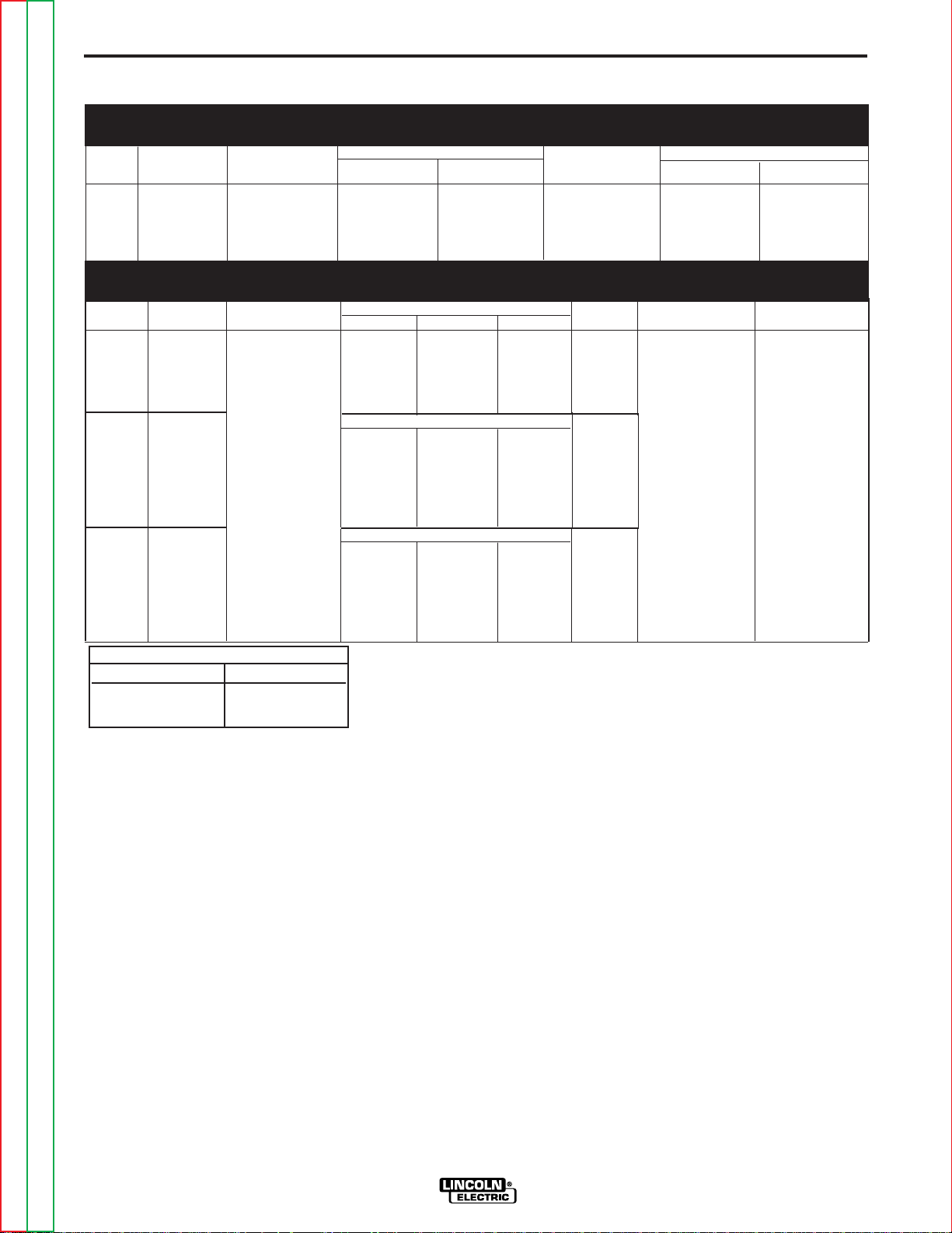
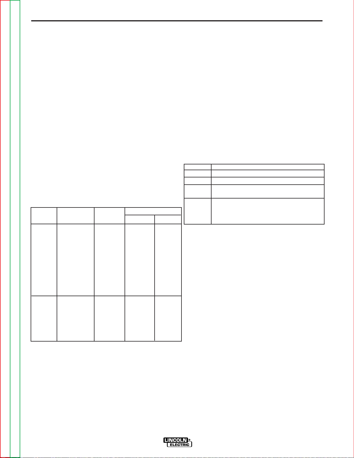
TECHNICAL SPECIFICATIONS
: Power Feed 10M Single Wire Feeder
WIRE DRIVE OR WIRE DRIVE SECTION OF FEEDER
SPEC.# TYPE LOW SPEED RATIO HIGH SPEED RATIO
Wire Size Wire Size
K2230-1
K2314-1
Bench Model
Boom Model
Low Speed Solid Cored High Speed Solid Cored
50-800 IPM .025 - 3/32 in. .035 - .120 in 75 - 1200 IPM .025 - 1/16 in. .035 - 5/64 in.
(1.27-20.3 m/m) (0.6 - 2.4 mm) (0.9 - 3.0 mm) (2.0 - 30.5 m/m) (0.6 - 1.6 mm) (0.9 - 2.0 mm)
CONTROL BOX, WIRE DRIVE AND COMPLETE UNITS
SPEC.# TYPE INPUT POWER PHYSICAL SIZE• TEMPERATURE RATING
Height Width Depth Weight Operating Storage
K2230-1
Bench
Model
Feeder
K2314-1
Boom Box only ( 330 mm) (215 mm) (105 mm) (3.8 Kg.) (-10°C to 40°C) (-40°C to 40°C)
Model
Feeder
Wire Drive & 18.5“ 13.5“ 30.5“ 62 Lbs
Reel Stand ( 470 mm) (345 mm) (775 mm) (28.1 Kg.)
Height Width Depth Weight
Control 40VDC 13.0“ 8.5“ 4.0“ 8.5 Lbs 14°F to 140°F -40°F to 185°F
Height Width Depth Weight
Dimensions
Dimensions ∆
Dimensions ∆
K2314-1
Boom Unit only ( 195 mm) (325 mm) (345 mm) (13.6 Kg.)
Model
Feeder
Wire Drive 7.6“ 12.9“ 13.7“ 30 Lbs
WELDING CAPACITY RATING
Amp Rating Duty Cycle
600 A 60%
500 A 100%
∆ Dimensions do not include wire reel.
Return to Master TOC Return to Master TOC Return to Master TOC Return to Master TOC
Return to Section TOC Return to Section TOC Return to Section TOC Return to Section TOC
POWER FEED 10M SINGLE/DUAL
Page 9

A-3 A-3
INSTALLATION
SAFETY PRECAUTION
ELECTRIC SHOCK can kill.
• Only qualified personnel should
perform this installation.
• Turn off the input power to the
power source at the disconnect
switch or fuse box before working
on this equipment. Turn off the
input power to any other equipment
connected to the welding system at
the disconnect switch or fuse box
before working on this equipment.
• Do not touch electrically hot parts.
----------------------------------------------------------------------------------------
LOCATION
• The Power Feed 10M Single Wire Feeder has an
IP21 rating, suitable for indoor use.
• The Power Feed 10M Single Wire Feeder should be
operated in a substantially upright position.
• Do not submerge the Power Feed 10M Single Wire
Feeder.
• The Power Feed 10M Single Wire Feeder is not suit-
able for stacking.
MOUNTING
Wire Drive Mounting (See Figure A.1)
The wire drive may be mounted by using the four holes
on the bottom. Because the feed plate and gearbox are
electrically "hot" when welding, make certain the parts
do not contact the any structure or person.
Mount the wire drive with the drive rolls in the vertical
plane to prevent dirt from collecting in the wire drive.
Angle the drive and feed plate to prevent sharp bends
in the gun and cable and incoming wire.
Control Box Mounting (See Figure A.2)
Boom model Power Feed 10M Single Wire Feeder's
feature a control box that mounts separately from the
wire drive.
The back of the control box has four keyhole slots for
mounting. #10 screws are recommended for mounting.
Locate the Power Feed 10M Single Wire Feeder away
from radio controlled machinery. The normal operation
of the Power Feed 10M Single Wire Feeder may
adversely affect the operation of RF controlled equipment, which may result in bodily injury or damage to
the equipment.
FIGURE A.1
FIGURE A.2
Return to Master TOC Return to Master TOC Return to Master TOC Return to Master TOC
Return to Section TOC Return to Section TOC Return to Section TOC Return to Section TOC
POWER FEED 10M SINGLE/DUAL
Page 10
A-4 A-4
INSTALLATION
SAFETY PRECAUTION
CAUTION
ELECTRIC SHOCK can kill.
• Only qualified personnel should
perform this installation.
• Turn off the input power to the
power source at the disconnect
switch or fuse box before working
on this equipment. Turn off the
input power to any other equipment
connected to the welding system at
the disconnect switch or fuse box
before working on this equipment.
• Do not touch electrically hot parts.
----------------------------------------------------------------------
WELD CABLE SIZING
Minimum work and electrode cables sizes are as follows:
T ABLE A.1
(Current (60% Duty Cycle)
400 Amps 2/0 (67 mm2)
500 Amps 3/0 (85 mm2)
600 Amps 3/0 (85 mm2)
NOTE: K1796 coaxial welding cable is recommended
to reduce the cable inductance in long distance Pulse
or STT applications up to 300 amps.
MINIMUM COPPER
WORK CABLE SIZE AWG
Up To-100 Ft. Length (30 m)
WELD CABLE CONNECTION
Connect a work lead of sufficient size and length (Per
Table A.1) between the proper output terminal on the
power source and the work. Be sure the connection to
the work makes tight metal-to-metal electrical contact.
To avoid interference problems with other equipment
and to achieve the best possible operation, route all
cables directly to the work or wire feeder. Avoid excessive lengths and do not coil excess cable.
When using an inverter type power source like the
Power Waves, use the largest welding (electrode
and work) cables that are practical. At least 2/0
copper wire - even if the average output current
would not normally require it. When pulsing, the
pulse current can reach very high levels. Voltage
drops can become excessive, leading to poor
welding characteristics, if undersized welding
cables are used.
------------------------------------------------------------------------
WELD CABLE SIZES
Table A.2 has the copper cable sizes recommended
for different currents and duty cycles. Lengths stipulated are the distance from the welder to work and
back to the welder again. Cable sizes are increased
for greater lengths primarily for the purpose of minimizing voltage in the welding circuit.
ELECTRODE LEAD
Most welding applications run with the electrode being
positive (+). For those applications, connect the electrode cable between the wire feeder and the positive
(+) output stud on the power source. Connect the lug
at the other end of the electrode cable to the wire drive
feed plate. Be sure the connection to the feed plate
makes tight metal-to-metal electrical contact. The electrode cable should be sized according to the specifications given in the work cable connections Table A.1.
Connect a work lead from the negative (-) power
source output stud to the work piece. The work piece
connection must be firm and secure, especially if pulse
welding is planned.
T ABLE A.2
RECOMMENDED CABLE SIZES (RUBBER COVERED COPPER - RATED 75°C)**
CABLE SIZES FOR COMBINED LENGTHS OF ELECTRODE AND WORK CABLES
Percent
Duty
Amperes
325
350
400
400
500
** Tabled values are for operation at ambient temperatures of 40°C and below. Applications above 40°C may require cables larger than
recommended, or cables rated higher than 75°C.
Return to Master TOC Return to Master TOC Return to Master TOC Return to Master TOC
Return to Section TOC Return to Section TOC Return to Section TOC Return to Section TOC
Cycle
100
60
60
100
60
0 to 50 Ft.
0 to 15 m
2/0
1/0
2/0
3/0
2/0
POWER FEED 10M SINGLE/DUAL
50 to 100Ft.
15 to 31 m
2/0
1/0
2/0
3/0
2/0
100 to 150 Ft.
31 to 48 m
2/0
2/0
2/0
3/0
3/0
150 to 200 Ft.
48 to 61 m
2/0
2/0
3/0
3/0
3/0
200 to 250 Ft.
61 to 76 m
3/0
3/0
4/0
4/0
4/0
Page 11
A-5 A-5
Electrode
Work
Work
Power Source
Work
Electrode
Wire Feeder
Electrode
Work
Coaxial Weld Cable
INSTALLATION
For Electrode Connect the Connect the
Polarity: Electrode lead to work lead to
Positive Positive Stud Negative
Negative Negative Stud
For additional Safety information regarding the electrode and work cable set-up, See the standard "SAFETY INFORMATION" located in the front of the
Instruction Manuals.
Positive Stud
CAUTION
Excessive voltage drops caused by poor work
piece connections often result in unsatisfactory
welding performance.
------------------------------------------------------------------------
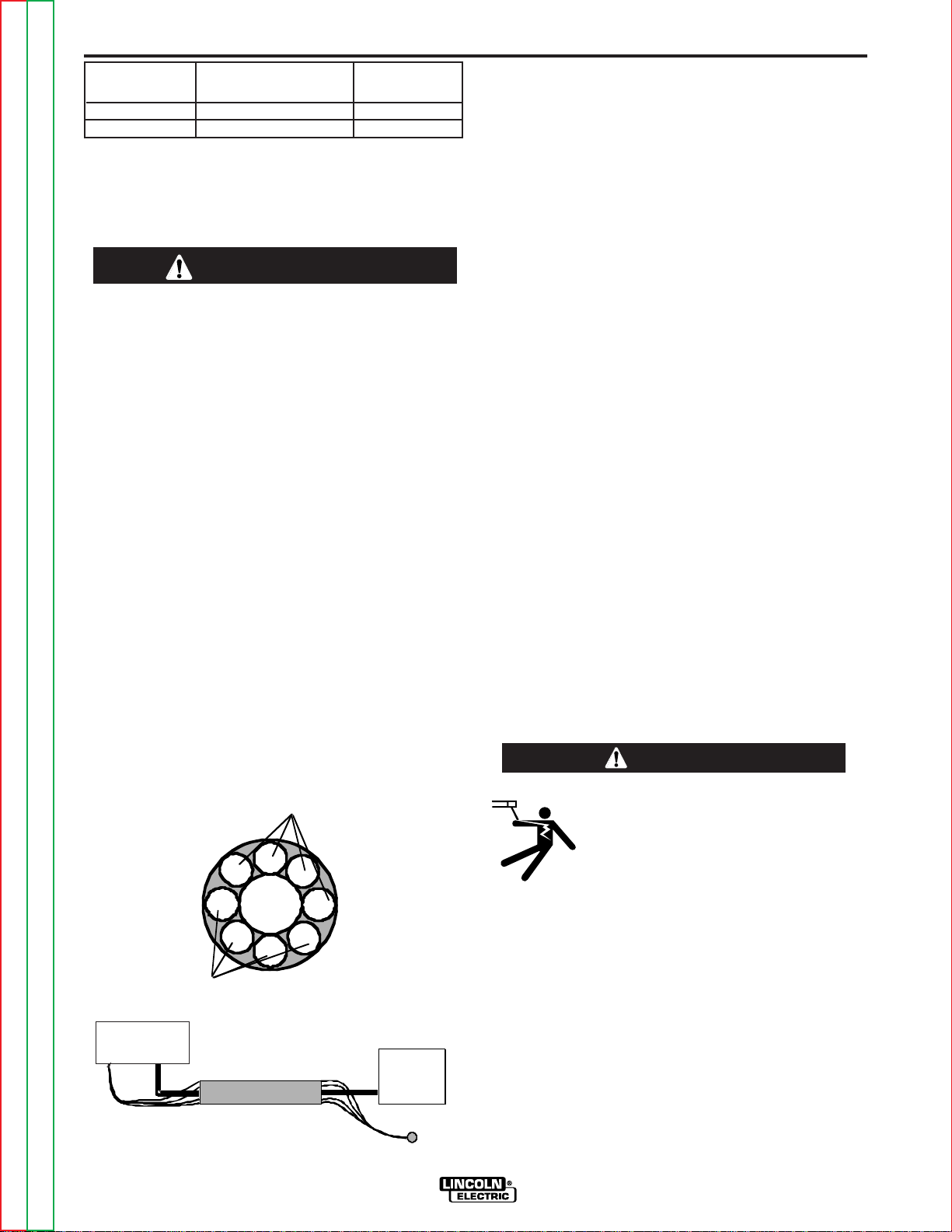
COAXIAL WELD CABLES
Coaxial welding cables are specially designed welding
cables for pulse welding or STT welding. Coaxial weld
cables feature low inductance, allowing fast changes in
the weld current. Regular cables have a higher inductance which may distort the pulse or STT wave shape.
Inductance becomes more severe as the weld cables
become longer.
Coaxial weld cables are recommended for all pulse
and STT welding, especially when the total weld cable
length (electrode cable + work cable) exceeds 50 feet
(7.6m)
A coaxial weld cable is constructed by 8 small leads
wrapped around one large lead. The large inner lead
connects to the electrode stud on the power source
and the electrode connection on the wire feeder. The
small leads combine together to form the work lead,
one end attached to the power source and the other
end to the work piece.
(See Coaxial weld Cable below.)
CHANGING ELECTRODE POLARITY
SETTING
The Power Feed 10M Single Wire Feeder is preset at
the factory for Electrode Positive welding. (See Figure
A.3)
NOTE: Changing this DIP Switch does not change the
actual welding polarity. The actual welding polarity is
changed by reversing the welding cables at the power
source output studs.
This DIP Switch setting must coincide with the polarity
you are setting up to weld with for the feeder to operate correctly. Operating the Power Feed 10M Single
Wire Feeder with the DIP switch in the wrong position
will cause very erratic weld characteristics.
NEGATIVE ELECTRODE POLARITY
This options allows for the setting of negative polarity
sensing when a negative polarity welding process is
performed.
When negative electrode polarity is required, such as
in some Innershield applications, reverse the output
connections at the power source (electrode cable to
the negative (-) stud, and work cable to the positive (+)
stud).
When operating with electrode polarity negative the
Power Feed 10M Single Wire Feeder must be set to
recognize this set-up.
(See Figure A.3)
To change the electrode polarity DIP Switch setting:
WARNING
Return to Master TOC Return to Master TOC Return to Master TOC Return to Master TOC
Return to Section TOC Return to Section TOC Return to Section TOC Return to Section TOC
• Always wear dry insulating gloves.
-----------------------------------------------------------
1. Turn off power at the welding power source.
2. Remove the rear access panel on the wire drive.
3. Locate the DIP switches on the Wire Drive Board.
4. Set DIP switch #7 to the desired polarity
5. Reinstall the rear access panel and restore power.
POWER FEED 10M SINGLE/DUAL
• Do not touch electrically live parts or
electrodes with your skin or wet
clothing.
• Insulate yourself from the work and
gr
ound.
.
Page 12
A-6 A-6
Welding Gun
Wire Feed er
A
mphenol
A
B
C
D
E
Trigger Lead
Wire F eeder
Power So
urc
e
Amphenol Plug
Amphenol Plug
A
B
C
D
E
A
B
C
D
E
INSTALLATION
DIP Switch #7 Position
ON
OFF
Polarity
(negative) - polarity
(positive) + polarity
FIGURE A.3
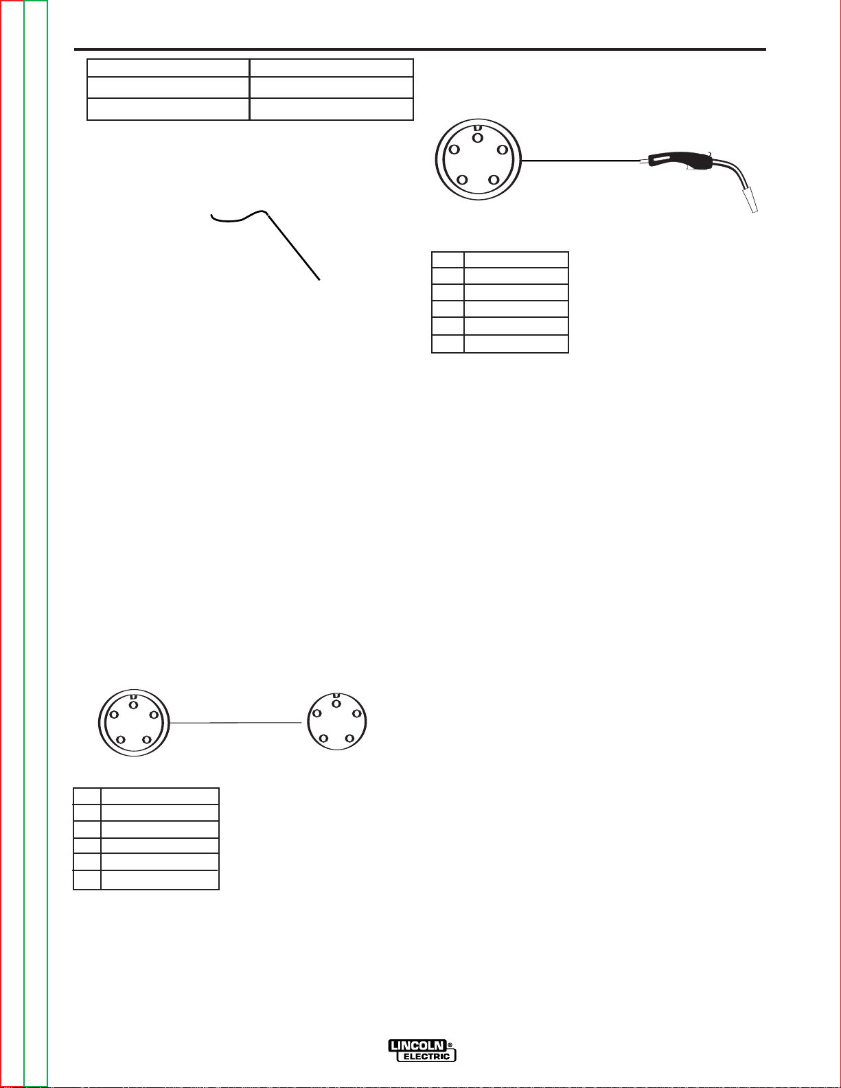
CONTROL CABLE
CONTROL CABLE CONNECTIONS
• All system control cables are the same.
• All control cables can be connected end to end to
extend their length.
• All system equipment must be connected to a control cable.
Typical Bench Feeder Connection:
Control cable is connected from the Power Wave
Source output Amphenol receptacle to the input
Amphenol receptacle on the back of the Wire Drive.
Digital Control Cable, K1543-xx
Welding Gun/Wire Feeder Trigger Connector
Wire Feeder
Pin Function
A Gun T
rigger
BC Common
D
Dual Procedure
E Common
CONTROL CABLE SPECIFICATIONS
It is recommended that only genuine Lincoln control
cables be used at all times. Lincoln cables are specifically designed for the communication and power
needs of the Power Wave Source / Power Feed system. The use of non-standard cables, especially in
lengths greater than 25ft(7.6m), can lead to communication problems (system shutdowns), poor motor
acceleration (poor arc starting) and low wire driving
force (wire feeding problems).
Lincoln control cables are copper 5 conductor cable in
a SO-type rubber jacket. There is one 20 gauge twisted pair for network communications. This pair has an
impedance of approximately 120 ohms and a propagation delay per foot of less than 2.1 nanoseconds.
There are two 12 gauge conductors that are used to
supply the 40 VDC to the network. The fifth wire is 18
gauge and is used as an electrode sense lead.
Return to Master TOC Return to Master TOC Return to Master TOC Return to Master TOC
Return to Section TOC Return to Section TOC Return to Section TOC Return to Section TOC
Pin
Function
A Digital I/O
B Digital I/O
C "67" voltage sense
D
40 VDC
E 40 VDC
Use a maximum of 250 feet (76.2m) of control cable
between components.
POWER FEED 10M SINGLE/DUAL
AVAILABLE CONTROL CABLE
K1543 Control cable only. Available in lengths of
8'(2.4m), 16'(4.9m), 25'(7.6m), 50'(15.2m) and
100'(30.5m).
Page 13

A-7 A-7
INSTALLATION
WIRE DRIVE SYSTEMS
Drive Roll Kits are designed to feed specific types and
wire sizes. The Power Feed 10M Single Wire Feeder
does not include these Drive Roll Kits with this Wire
Drive, but are available for ordering from the following
tables:
Drive Roll Kits, Steel Wires
Includes: 4 Smooth V groove drive rolls and an inner
wire guide.
KP1505-030S .023-.030 (0.6-0.8mm)
KP1505-035S .035 (0.9mm)
KP1505-045S .045 (1.2mm)
KP1505-052S .052 (1.4mm)
KP1505-1/16S 1/16 (1.6mm)
Drive Roll Kits, Cored W
Includes: 4 Knurled drive rolls and an inner wire guide.
KP1505-035C .030-.035" (0.8-0.9mm)
KP1505-045C .040-.045" (1.0-1.2mm)
KP1505-052C .052" (1.4mm)
KP1505-1/16C 1/16" (1.6mm)
ires
CHANGING DRIVE ROLLS AND WIRE
GUIDES
FIGURE A.4
WIRE DRIVE DOOR
(OPEN)
ITEM DESCRIPTION
1 Inner Wire Guide
2 Drive Rolls
3 Outer Wire Guide
Drive Roll Kits, Steel or Cored Wires
Includes: 4 Knurled drive rolls and an inner wire guide.
KP1505-068 .068-.072" (1.8mm)
KP1505-5/64 5/64" (2.0mm)
KP1505-3/32 3/32" (2.4mm)
KP1505-7/64 7/64" (2.8mm)
KP1505-.120 .120" (3.2mm)
Drive Roll Kits, Hardfacing Wires
Includes: 2 Knurled drive rolls, 2 Smooth V groove
drive rolls and an inner wire guide.
KP1505-7/64C 7/64" (2.8mm)
Drive Roll Kits,
Includes: 4 polished U groove drive rolls, outer wire
guide and an inner wire guide.
KP1507-035A .035" (0.9 mm)
KP1507-040A .040" (1.0mm)
KP1507-3/64A 3/64" (1.2mm)
KP1507-1/16A 1/16" (1.6mm)
KP1507-3/32A 3/32" (2.4mm)
Aluminum Wire
o change drive rolls and wire guides:
T
1. Turn off power at the welding power source.
2. Open wire drive door.
3. Remove the outer wire guide. (Item #3)
4. Remove the 4 drive rolls (Item #2) by pulling them
straight off of the drive hub. Rock the upper drive
rolls back for ease of removal.
5. Remove the inner wire guide (Item #1).
6. Insert the new inner wire guide (Item #1) over the
locating pins of the feed plate.
7. Install each drive roll by pushing it onto the hub until
it fully seats.
8. Install the outer wire guide.
9. Swing the upper drive rolls down and close the wire
drive door
.
Return to Master TOC Return to Master TOC Return to Master TOC Return to Master TOC
Return to Section TOC Return to Section TOC Return to Section TOC Return to Section TOC
POWER FEED 10M SINGLE/DUAL
Page 14
A-8 A-8
1
2
3
4
NOTES
DRIVE ROLL PRESSURE SETTING
The Power Feed 10M Single Wire Feeder is factory set
with the pressure indicator approximately "2". The best
drive roll pressure varies with wire type, wire surface,
lubrication and hardness. Too much pressure could
cause "birdnesting", but too little pressure could cause
slippage.
Set the drive roll pressure by:
1. Press the end of the gun against a solid object that
is electrically isolated from the welder output and
press the gun trigger for several seconds.
2. If the wire "birdnests" or jams, the drive roll pressure
is too high. Reduce the pressure by one turn of the
knob, run new wire through the gun, and repeat step
1.
If the only result is slippage, disconnect the gun and
3.
pull the gun cable forward about 6" (150mm). There
should be a slight waviness in the exposed wire. If
there is no waviness, increase the pressure setting
one turn, reconnect the gun and repeat the above
steps.
CHANGING THE GUN RECEIVER BUSHING
Gun receiver bushings make it easy to switch from one
gun to another.
Tools required:
1/4" Allen wrench
To change the gun bushing:
1. Turn off power at the welding power source.
2. Remove the welding wire from the wire drive.
3. Remove the thumb screw from the wire drive.
4. Remove the welding gun from the wire drive.
5. Loosen the socket head cap screw that holds the connector bar against the gun bushing. Important: Do not
attempt to completely remove the socket head cap
screw.
6. Remove the outer wire guide, and push the gun bush-
ing out of the wire drive. Because of the precision fit,
light tapping may be required to remove the gun bushing.
7. Disconnect the shielding gas hose from the gun bush-
ing, if required.
8. Connect the shielding gas hose to the new gun bush-
ing, if required.
9. Rotate the gun bushing until the thumb screw hole
aligns with the thumb screw hole in the feed plate.
Slide the gun receiver bushing into the wire drive and
verify the thumb screw holes are aligned.
Note: Some gun bushings do not require the use of the
thumb screw.
10. Tighten the socket head cap screw
.
11. Insert the welding gun into the gun bushing and tight-
en the thumb screw.
Gun Receiver For use With
Bushing
K1500-1 K466-1 Lincoln gun connectors;
Innershield and Subarc guns)
K1500-2 K466-2, K466-10 Lincoln gun
connectors; Magnum 200/300/400
guns and compatible with T
#4)
K1500-3 K1637-7 Lincoln gun connectors;
FIGURE A.5
ITEM DESCRIPTION
1 Thumb Screw
2 Gun Receiver Bushing
3 Connector Bar
Return to Master TOC Return to Master TOC Return to Master TOC Return to Master TOC
Return to Section TOC Return to Section TOC Return to Section TOC Return to Section TOC
4 Socket Head Cap Screw
POWER FEED 10M SINGLE/DUAL
K1500-4 K466-3 Lincoln gun connectors;
K1500-5 (Compatible with Oxo® guns.)
K489-7 ( Lincoln Fast-Mate guns.)
Magnum 550 guns and compatible
with Tweco® #5)
compatible with Miller® guns.)
weco®
Page 15

A-9 A-9
WIRE DRIVE UNIT
THUMB SCREW
GUN RECEIVER BUSHING
TRIGGER RECEPTACLE
GUN TRIGGER
CONNECTOR
CABLE CONNECTOR
END K466-10
FIGURE A.5a
GUN NOZZLE
GUN HANDLE
GUN TUBE
GUN AND CABLE
INSTALLATION
WELDING GUNS, TORCHES AND ACCESSORIES
GUN RECEIVER BUSHING
The Power Feed 10M Single Wire Feeder comes with
a K1500-2 gun receiver bushing, for use with the
Magnum gun with a K466-10 connector kit which .
The Power Feed 10M Single Wire Feeder Push Pull
model comes with a S25398 gun receiver bushing, for
use with the push pull gun. K2154-1 push-pull torch
connector kit is optional.
The bushing must be changed if the Power Feed 10M
Single Wire Feeder is going to be switched from the
push set up to the push-pull set up or vise versa.
Spool Guns are not recommended with the Power
Feed 10M Single Wire Feeder.
MAGNUM GUN AND CABLE ASSEMBLIES
The Power Feed 10M Single Wire Feeder model will
accept a number of optional gun and cable assemblies.
An example of installing the Gun and Cable is shown in
Figure A.5a with a 15 ft. (4.6m) long Magnum gun and
cable.
1. Turn off power at the welding power source.
2. Unscrew Thumb screw on Wire Drive Unit, until tip
of screw no longer protrudes into gun bushing hole
as seen from the front of machine.
3. Fully insert the gun cable connector end into the
gun receiver bushing and gently tighten the thumb
screw as show in Figure A.5a below.
4. Connect the gun trigger connector to the trigger
receptacle. Make sure that the key ways are
aligned, insert and tighten retaining ring.
Return to Section TOC Return to Section TOC Return to Section TOC Return to Section TOC
Return to Master TOC Return to Master TOC Return to Master TOC Return to Master TOC
POWER FEED 10M SINGLE/DUAL
Page 16
A-10 A-10
INSTALLATION
WIRE FEED SHUT DOWN CIRCUIT
The wire feed shut down circuit is used to stop the wire
feed in the event of a fault. The most common use of
the circuit is with water cooled guns. A flow sensor is
connected to the circuit to protect the welding gun if the
water flow is interrupted.
The Power Feed 10M Single Wire Feeder has two
leads, 570A and 570B, located inside the wire drive
that are electrically common. If flow switch is used,
separate these leads and connect to normally closed
flow switch terminals when water is flowing. Connect
the flow sensor to these two leads.
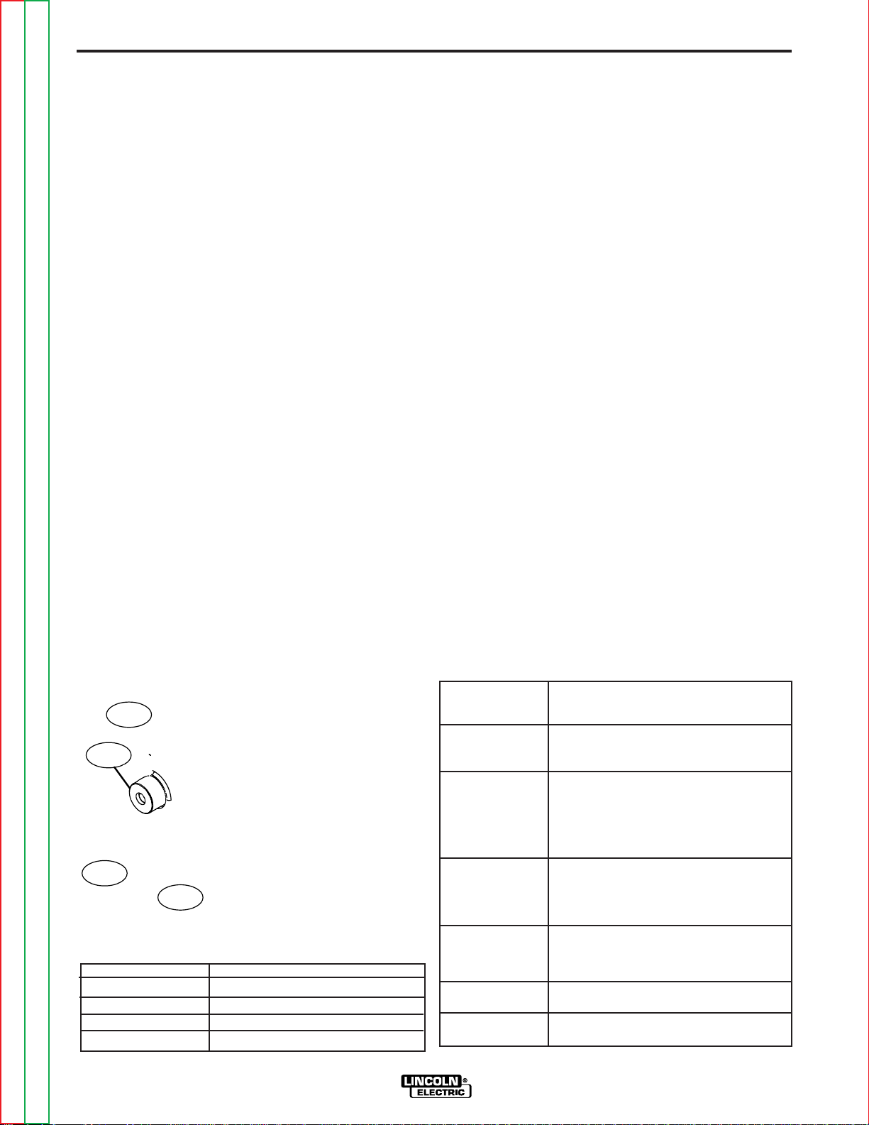
CHANGING THE GEAR RATIO
The Power Feed 10M Single Wire Feeder wire drive
may be configured for either low speed or high speed,
depending upon the application. The wire feeders are
factory assembled for low speed operation and include
a gear for high speed operation.
Gear
Ratio
Low Speed
High Speed
Purpose:
Best for most
GMAW and FCAW
welding. The low
speed gear ratio
provides the most
force for pushing
wires through long
guns or pulling
wire through conduits.
Suitable only for
small diameter
wires operating at
high wire feed
speeds. Feeding
force is less.
Speed
50-800 ipm
(1.27-20.3 m/m)
75-1200 ipm
(2.03-30.5 m/m)
Wire Size
Solid
.025-3/32 in.
(0.6 - 2.4 mm)
.025-1/16 in
.(0.6 - 1.6 mm)
Core
.035 - .120 in.
(0.9 - 3.0
mm)
.035 - 5/64 in.
(0.9 - 2.0
mm)
FIGURE A.6
ITEM DESCRIPTION
1 Gear.
2 Screw holding feed plate to wire feeder
.
3 Low speed position, screw holding feed
plate to wire feeder.
4 High speed position, screw holding feed
plate to wire feeder.
To change the gear ratio:
1. Turn off power at the welding power source.
2. Open the wire drive door.
3. Use a 3/16"
Allen wrench to remove the screws
holding the feed plate to the wire feeder.
4. Use a Phillips screwdriver to remove the screw and
washers holding the gear to the shaft.
5. Remove the gear.
6. Lightly cover the shaft with engine oil or equivalent.
Install the desired gear onto the shaft.
7. Reassemble the screw and washers securing the
gear to the shaft.
8. Reassemble the screws in the appropriate position
for holding the feed plate to the wire feeder.
Return to Master TOC Return to Master TOC Return to Master TOC Return to Master TOC
Return to Section TOC Return to Section TOC Return to Section TOC Return to Section TOC
POWER FEED 10M SINGLE/DUAL
Page 17

A-11 A-11
L
OW SPEED
SCREW SETTING
H
IGH SPEED
SCREW SETTING
SCREW FOR ROTATING
FEED PLATE
C
LAMPING COLLAR SCREWS
INSTALLATION
WIRE REEL LOADING
Spindle Placement
The wire reel stand provides two mounting locations
for the spindle. Each mounting location consists of a
tube in the center of the mast and locating slots.
Loading 16 to 44 lb. (7.3 – 20kg) Spools
1. Squeeze the release bar on the retaining collar and
9. Loosen the two screws on the bottom of the feed
plate clamping collar.
10. Rotate the feed plate to the desired position.
11. Tighten the two screws on the bottom of the feed
plate clamping collar.
FIGURE A.7
remove it from the spindle.
2. Place the spool on the spindle, aligning the spindle
brake pin with one of the holes in the back side of
the spool.
An indicator mark on the end of the spindle shows the orientation of the brake holding pin.
Be certain the wire feeds off of the spool in the proper direction.
3. Re-install the retaining collar. Make sure that the
release bar snaps out and that the retaining collar
fully engages the groove on the spindle.
Loading 10 to 15 lb. (4.5 – 6.8kg) Spools
DIP Switch #8 Position
ON
OFF
Gear Ratio
High speed
Low speed (default)
12. Remove the rear access panel on the wire drive.
13. Locate DIP switches on the Wire Drive Board.
14. Set DIP
switch #8 to the desired polarity.
15. Reinstall the rear access panel to the wire drive.
16. Restore power.
A K419 spindle adapter is required for loading 2" wide
spools on 2" (51mm) spindles. Use a K419-1 spindle
adapter for loading 2-1/2" (64mm) wide spools.
1. Squeeze the release bar on the retaining collar and
remove it from the spindle.
2. Place the spindle adapter on the spindle, aligning
the spindle brake pin with the hole in the adapter.
3. Place the spool on the spindle and align the adapter
brake tab with one of the holes in the back side of
the spool.
An indicator mark on the end of the spindle shows the orientation of the brake tab. Be certain the wire feeds off of the spool in the proper
direction.
4. Re-install the retaining collar. Make sure that the
release bar snaps out and that the retaining collar
fully engages the groove on the spindle.
Return to Master TOC Return to Master TOC Return to Master TOC Return to Master TOC
Return to Section TOC Return to Section TOC Return to Section TOC Return to Section TOC
POWER FEED 10M SINGLE/DUAL
Page 18

A-12 A-12
SPINNER
NUT
CARDBOARD
LINER
COVER
PLATE
TIE
WIRE
SPRING
ARM
REEL
COIL
SLOTS
INSTALLATION
Using K1504-1 Coil Reel
50-60 lb. (22.7 - 27.2 kg) Coil Mounting
(See Figure A.10)
1. Make sure the spindle of the wire reel stand is in the
upper position.
With the coil reel assembly mounted to a 2" (51mm)
2.
spindle, loosen the spinner nut and remove the
cover plate. Alternatively, lay the coil reel assembly
flat on the floor and loosen the spinner nut and
remove the cover plate.
3. Place the coil of electrode on the reel so it unwinds
from the bottom as it rotates.
4. Tighten the spinner nut as much as possible by
hand using the cover plate spokes for leverage. DO
NOT hammer on the spinner nut.
5. Cut and remove only the tie wire holding the free
end of the coil. Hook the free end around the rim of
the cover plate and secure it by wrapping it around.
Cut and remove remaining tie wires.
FIGURE A.10
CAUTION
• Always be sure the free end of the coil is secure-
ly held while the tie wires are being cut and until
the wire is feeding through the drive rolls. Failure
to do this will result in "backlashing" of the coil,
which may tangle the wire. A
feed and must either be untangled or discarded.
------------------------------------------------------------------------
6. Be sure the coil is engaged with the spindle brake
pin and the release bar on the retaining collar "pops
up". The retaining collar must fully engage the
retaining groove on the spindle.
tangled coil will not
Return to Master TOC Return to Master TOC Return to Master TOC Return to Master TOC
Return to Section TOC Return to Section TOC Return to Section TOC Return to Section TOC
POWER FEED 10M SINGLE/DUAL
Page 19

A-13 A-13
SPINDLE
BRAKE
PIN
GROOVES
ADAPTER
RETAINING
SPRING
READI REEL
CAGE
WIRE
RELEASE
BAR
RETAINING
COLLAR
INSTALLATION
Loading 30 lb. (13.6 kg) Readi-Reels
(See Figure A.11)
A K363-P Readi-Reel adapter is required for loading
these spools on 2" (51mm) spindles.
1. Squeeze the release bar on the retaining collar and
remove it from the spindle.
2. Place the Readi-Reel adapter on the spindle, aligning the spindle brake pin with one of the holes in the
adapter.
3. Re-install the retaining collar. Make sure that the
release bar snaps out and that the retaining collar
fully engages the groove on the spindle.
4. Rotate the spindle and adapter until the retaining
spring is at the 12 o’clock position.
5. Position the Readi-Reel so that electrode de-reels in
the proper direction.
6. Set one of the Readi-Reel inside cage wires on the
slot in the retaining spring.
7. Lower the Readi-Reel to depress the retaining
spring and align the other inside cage wires with the
grooves in the adapter.
Removing a Readi-Reel
1. To remove a Readi-Reel from the an adapter,
depress the retaining spring with a thumb while
pulling the Readi-Reel cage from the adapter with
both hands. Do not remove the adapter from the
spindle.
WELD WIRE ROUTING
The electrode supply may be either from reels, ReadiReels, spools, or bulk packaged drums or reels.
Observe the following precautions:
a) The electrode must be routed to the wire drive unit
so that the bends in the wire are at a minimum,
and also that the force required to pull the wire
from the reel into the wire drive unit is kept at a
minimum.
b) The electrode is “hot” when the gun trigger is
pressed and must be insulated from the boom and
structure.
c) If more than one wire feed unit shares the same
boom and are not sharing the some power source
output stud, their wire and reels must be insulated
from each other as well as insulated from their
mounting structure.
8. Slide the cage all way onto the adapter until the
retaining spring "pops up" fully.
FIGURE A.11
Return to Master TOC Return to Master TOC Return to Master TOC Return to Master TOC
Return to Section TOC Return to Section TOC Return to Section TOC Return to Section TOC
POWER FEED 10M SINGLE/DUAL
Page 20

A-14 A-14
INSTALLATION
SHIELDING GAS CONNECTION
NOTE: Gas supply pressure must be regulated to a
maximum of 80 psi(5.5 bar).
Install the shielding gas supply as follows:
1. Secure the cylinder to prevent it from falling.
2. Remove the cylinder cap. Inspect the cylinder
valves and regulator for damaged threads, dirt, dust,
oil or grease. Remove dust and dirt with a clean
cloth. DO NOT ATTACH THE REGULATOR IF OIL,
GREASE OR DAMAGE IS PRESENT! Inform your
gas supplier of this condition. Oil or grease in the
presence of high pressure oxygen is explosive.
3. Stand to one side away from the outlet and open the
cylinder valve for an instant. This blows away any
dust or dirt which may have accumulated in the
valve outlet.
4. Attach the flow regulator to the cylinder valve and
tighten the union nut(s) securely with a wrench.
Note: if connecting to 100% CO
ulator adapter between regulator and cylinder valve.
If adapter is equipped with a plastic washer, be sure
it is seated for connection to the CO
5. Attach one end of the inlet hose to the outlet fitting
of the flow regulator. Attach the other end to the
welding system shielding gas inlet. Tighten the
union nuts with a wrench.
6. Before opening the cylinder valve, turn the regulator
adjusting knob counterclockwise until the adjusting
spring pressure is released.
7. Standing to one side, open the cylinder valve slowly
a fraction of a turn. When the cylinder pressure gage
stops moving, open the valve fully.
8. The flow regulator is adjustable. Adjust it to the flow
rate recommended for the procedure and process
being used before making a weld.
cylinder,insert reg-
2
cylinder.
2
Return to Master TOC Return to Master TOC Return to Master TOC Return to Master TOC
Return to Section TOC Return to Section TOC Return to Section TOC Return to Section TOC
POWER FEED 10M SINGLE/DUAL
Page 21
A-15 A-15
INSTALLATION
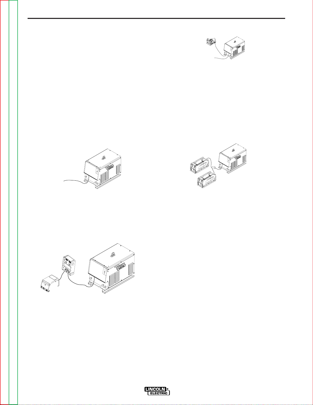
EXAMPLES OF CONNECTING AN
ARCLINK POWER WAVE SYSTEM
ArcLink Power Wave products may be configured in
many different ways. The flexible system allows multiple wire feeders to be connected to the same power
source. The diagrams represent some of the common
methods for connecting ArcLink Products.
Important: Bench model wire feeders cannot be separated into a separate control box and wire drive for a
boom system.
Common ArcLink Systems
The following Power Wave systems may all be assembled without any changes to the equipment DIP switches
Basic Semi-Automatic System
• Great for general fabrication.
Robotic/Semi-Automatic System
• Use the bench feeder for offline welding.
Shown with
• K2230-1 Power Feed 10M Single Wire Feeder
• K1780-2 PF-10/R
• K2203-1 Power Wave 455M/STT
• K2205-1 Wire Drive Module
Multiple Wire Feeder System
• Load one feeder with solid wire, the other with flux
cored.
Shown with
• K2230-1 Power Feed 10M Single Wire Feeder
• K2203-1 Power Wave 455M/STT
Boom Semi-Automatic System
• Often used when making large weldments.
Shown with
• K2314-1 Power Feed 10M Single W
(includes wire drive and control box)
• K2203-1 Power Wave 455M/STT
ire Feeder Boom
• Great for pipeline work.
Shown with
• K2429-1 ArcLink T Cable Connector
• K2196-1 Power Feed 15M
• K2203-1 Power Wave 455M/STT
ArcLink Systems
Many other ArcLink systems may be assembled
besides those shown in this manual. The majority will
self configure. If an assembled system flashes the status light green rapidly on all components, contact the
Lincoln Electric Company for further assistance.
Current Power Feed 10M models that will not self configure...
• K2316-1 Power Feed 10M Dual Boom
These configurations will require Dip Switches to be
set. See the power source instruction manual on how
to disable self configuration.
Return to Master TOC Return to Master TOC Return to Master TOC Return to Master TOC
Return to Section TOC Return to Section TOC Return to Section TOC Return to Section TOC
POWER FEED 10M SINGLE/DUAL
Page 22

A-16 A-16
CONTROL BOX
ROLL BAR
REEL STAND AND BASE ASSEMBLY
WIRE DRIVE
SPINDLE ASSEMBLY
Dig it al Control Cable
Work
Cable
E lec trod e C able
Shielding
G as H os e
Wire Feeder
Control Box
Welding G un
Pow er Source
+
-
Drive Roll
Kit
Tigger lead
Work Connection
INSTALLATION
BOOM CONFIGURATION
CONTROL BOX
WIRE DRIVE
BENCH MODEL FEATURES
Return to Section TOC Return to Section TOC Return to Section TOC Return to Section TOC
BASIC POWER FEED 10M SINGLE WIRE FEEDER WELDING SYSTEM CONFIGURATION
CV Welding:
Pulse Welding or STT Welding:
Return to Master TOC Return to Master TOC Return to Master TOC Return to Master TOC
POWER FEED 10M SINGLE/DUAL
Page 23

Section B-1 Section B-1
TABLE OF CONTENTS
- OPERATION SECTION -
Operation ................................................................................................................Section B
Safety Precautions .......................................................................................................B-2
Graphic Symbols..........................................................................................................B-2
Definitions of W
Common Welding Abbreviations..................................................................................B-3
Product Description......................................................................................................B-3
Recommended Processes ....................................................................................B-3/B-4
Required Equipment.....................................................................................................B-4
Front Panel Controls and Connections........................................................................B-6
1. Status LED .........................................................................................................B-6
2. Digital Meters and Output Encoder Knobs ................................................B-6/B-8
A. Wire Feed Speed/Ammeter Display and Output Knob ...............................B-6
B. Volts/Trim Display and Output Knob ...........................................................B-7
Synergic CV Voltage Display ............................................................................B-7
Overview:..........................................................................................................B-8
3. Mode Select Panel 4 (MSP4).............................................................................B-8
Layout-Controls................................................................................................B-8
Layout-Digital Displays.....................................................................................B-8
Power-up Sequence.........................................................................................B-9
Changing Weld Modes.....................................................................................B-9
Changing Arc Wave Control .............................................................................B-9
Changing Weld Sequence Behavior.................................................................B-9
Infrared (IR) Control ..........................................................................................B-9
Lockout/Security ..............................................................................................B-9
Limit Setting ...................................................................................................B-10
Machine Setup/User Preferences ..................................................................B-10
Accessing the Machine Setup Menu .............................................................B-10
Setup Features Menu............................................................................B-10/B-13
4. Cold Feed / Gas Purge Switch........................................................................B-13
5. 2-Step/4-Step Trigger Switch Operations .............................................B-13 /B-15
Process Set-Up and Operation......................................................................B-16
Steel and Stainless Synergic GMAW-P (Pulsed MIG) Welding......................B-17
Arc Control .....................................................................................................B-17
Aluminum Synergic GMAW-P (Pulsed MIG) and GMAW-PP (Pulse on Pulse)
Welding...........................................................................................................B-18
Machine Functionality by Weld Process ...............................................B-19/B-24
CC-Stick .........................................................................................................B-19
CV GMAW/FCAW (NON-SYNERGIC) ............................................................B-20
GMAW (SYNERGIC) .......................................................................................B-21
Pulse and Pulse-on-Pulse (SYNERGIC).........................................................B-22
STT and STT II (SYNERGIC) .........................................................................B-23
GTAW (Touch Start TIG) Welding ...................................................................B-24
User Memories.....................................................................................................B-25
6. Optional Dual Procedure / Memory Panel Operation......................................B-25
Limit Setting.........................................................................................................B-26
elding Modes ......................................................................................B-3
Return to Master TOC Return to Master TOC Return to Master TOC Return to Master TOC
POWER FEED 10M SINGLE/DUAL
Page 24

B-2 B-2
OPERATION
SAFETY PRECAUTIONS
Read this entire section of operating instructions
before operating the machine.
WARNING
ELECTRIC SHOCK can kill.
• Do not touch electrically live parts or
electrodes with your skin or wet
clothing.
• Insulate yourself from the work and
ground.
• Always wear dry insulating gloves.
• Do not use AC welder if your clothing, gloves or work area is damp or if
working on, under or inside workpiece.
Use the following equipment:
-DC manual (stick) welder.
-AC welder with reduced voltage
control.
• Do not operate with panels removed.
• Disconnect input power before servicing.
-------------------------------------------------------------
READ THIS WARNING, PROTECT YOURSELF &
OTHERS.
GRAPHIC SYMBOLS THAT APPEAR ON
THIS MACHINE OR IN THIS MANUAL
WIRE FEEDER
POSITIVE OUTPUT
NEGATIVE OUTPUT
PROTECTIVE
GROUND
WARNING OR
CAUTION
FUMES AND GASES can be dangerous.
• Keep your head out of fumes.
• Use ventilation or exhaust at the arc,
or both,to keep fumes and gases from
your breathing zone and general area.
WELDING SPARKS can cause fire or
explosion.
• Do not weld near flammable material.
• Do not weld on containers which have
held flammable material.
ARC RAYS can burn.
• Wear eye, ear, and body protection.
ONLY QUALIFIED PERSONS SHOULD INSTALL,
USE OR SERVICE THIS EQUIPMENT. READ AND
FOLLOW THE MANUFACTURER’S INSTRUCTIONS, EMPLOYER’S SAFETY PRACTICES AND
MATERIAL SAFETY DATA SHEETS (MSDS) FOR
CONSUMABLES.
-----------------------------------------------------------
Return to Master TOC Return to Master TOC Return to Master TOC Return to Master TOC
Return to Section TOC Return to Section TOC Return to Section TOC Return to Section TOC
POWER FEED 10M SINGLE/DUAL
Page 25

B-3 B-3
OPERATION
DEFINITIONS OF WELDING MODES
NON-SYNERGIC WELDING MODES
• A Non-synergic welding mode requires all welding
process variables to be set by the operator.
SYNERGIC WELDING MODES
• A Synergic welding mode offers the simplicity of sin-
gle knob control. The machine will select the correct
voltage and amperage based on the wire feed speed
(WFS) set by the operator
.
COMMON WELDING ABBREVIATIONS
WFS
• Wire Feed Speed
CC
• Constant Current
CV
• Constant Voltage
GMAW (MIG)
• Gas Metal Arc W
GMAW-P (MIG)
• Gas Metal Arc Welding-(Pulse)
elding
PRODUCT DESCRIPTION
General Physical Description
The Power Feed 10M Single Wire Feeder is a modular
wire feeder, consisting of two components - a wire
drive and a control box - are available assembled as
a bench unit or as a boom system. High speed, highly reliable digital cables connect the components
together and to the Power Wave power source.
The Power Feed 10M Single Wire Feeder system has
the ability to connect multiple wire feeders to one
power source, use the same power source to weld in
ferent locations (not simultaneously), or load a
two dif
different electrode on each feeder to eliminate change
over time.
The powerful four roll wire drive system sets the industry standard for ease of use. Its patented design allows
for tool-less change out of wire guides and drive rolls
greatly reducing set up time.
General Functional Description
• The Power Feed 10M Single Wire Feeder is a highly versatile wire feeder with easy to use features that
make it easy for the operator to adjust the arc for
specific preferences.
• The new MSP4 panel clearly displays key welding
information. Use the MSP4 panel to quickly adjust
weld settings, arc starting parameters, arc end parameters and set-up variables.
GMAW-PP (MIG)
• Gas Metal Arc Welding-(Pulse-on-Pulse)
AW (TIG)
GT
• Gas Tungsten Arc Welding
SMAW (STICK)
• Shielded Metal Arc Welding
FCAW (Innershield or Outershield)
• Flux Core Arc Welding
• The Power Feed 10M Single Wire Feeder wire feeder is provided with an infrared red (IR) port.
Transferring welding settings from one wire feeder to
another is accomplished with a common palm com
puter.
• When the Power Feed 10M Single Wire Feeder is
coupled to a Power Wave welding power source, the
result is a welding system with absolutely superior
arc performance.
-
RECOMMENDED PROCESSES
HF
• High Frequency
CAG
• Carbon Arc Gouging
Return to Master TOC Return to Master TOC Return to Master TOC Return to Master TOC
Return to Section TOC Return to Section TOC Return to Section TOC Return to Section TOC
POWER FEED 10M SINGLE/DUAL
The Power Feed 10M Single Wire Feeder is well suited for all MIG welding processes, giving premium arc
performance especially with unusual alloys and out of
position work.
• GMAW • SMAW
• GMAW-Pulse • GTAW (Touch Start TIG only)
• GMAW-STT • CAG
• FCAW
Page 26

B-4 B-4
PROCESS LIMITATIONS
The Power Feed 10M Single Wire Feeder is not suitable for:
• SAW
AW with HF
• GT
The MSP4 does not support "Spot" welding.
Not all weld modes or processes described in this manual are available on all Power Wave power sources.
OPERATION
REQUIRED EQUIPMENT
Lincoln’s Power Feed 10M Single Wire Feeder is
designed for use with the Power Wave family of power
sources. These include:
• Power Wave 355 • Power Wave 455M CE
• Power Wave 455 • Power Wave 455M STT
• Power Feed 455/STT • Power Wave 455M STT CE
• Power Wave 455M • Power Wave 655
ADDITIONAL REQUIRED EQUIPMENT
• Drive Roll Kits
• Control Cables
• Gun and Cable Assembly
• Weld Wire
• Shielding gas
• Work Cable and Clamp
EQUIPMENT LIMITATIONS
• The Power Feed 10M Single Wire Feeder does
operate with the Power Wave 450.
• The Power Feed 10M Single Wire Feeder does not
operate with any analog based power sources (CVxxx machines, DC-xxx machines, etc.)
• The Memory Panel is required to set procedure limits.
• The Boom model does not support push-pull guns or
GTAW welding.
• A push-pull gun and foot amptrol may not be plugged
into the Power Feed 10M Single Wire Feeder at the
same time.
not
Return to Master TOC Return to Master TOC Return to Master TOC Return to Master TOC
Return to Section TOC Return to Section TOC Return to Section TOC Return to Section TOC
POWER FEED 10M SINGLE/DUAL
Page 27

B-5 B-5
2
6
3
5
1
4
7
8
OPERATION
FRONT PANEL CONTROLS AND CONNECTIONS
FIGURE B.1- CASE FRONT CONTROLS
ITEM DESCRIPTION
1 Status LED indicates system status.
2
3 MSP4 Panel is used to set the weld mode, adjust the arc, change arc start/end para-
4 Cold Feed - Gas Purge Switch, press the switch up to feed wire with weld output off.
5 2 step - 4 step Switch is used to choose between a 2 step trigger or a 4 step trigger
6
7 Cover for Optional Water Cooling Kit, remove when the water cooling kit is installed.
8 Trigger Connector 5-pin amphenol for connecting the MIG gun trigger. See Installation
Return to Master TOC Return to Master TOC Return to Master TOC Return to Master TOC
Return to Section TOC Return to Section TOC Return to Section TOC Return to Section TOC
Digital Meter Display is a bright LED display of key welding information. Adjusting Parameter
Knobs.
meters and for set-up information.
Press the switch down for gas flow with weld output off.
operation.
Location for Optional Memory Panel. (Order K2360-1 for the memory panel. See Accessories
Section).
See instructions with water cooling Kit.
Section for detail.
POWER FEED 10M SINGLE/DUAL
Page 28
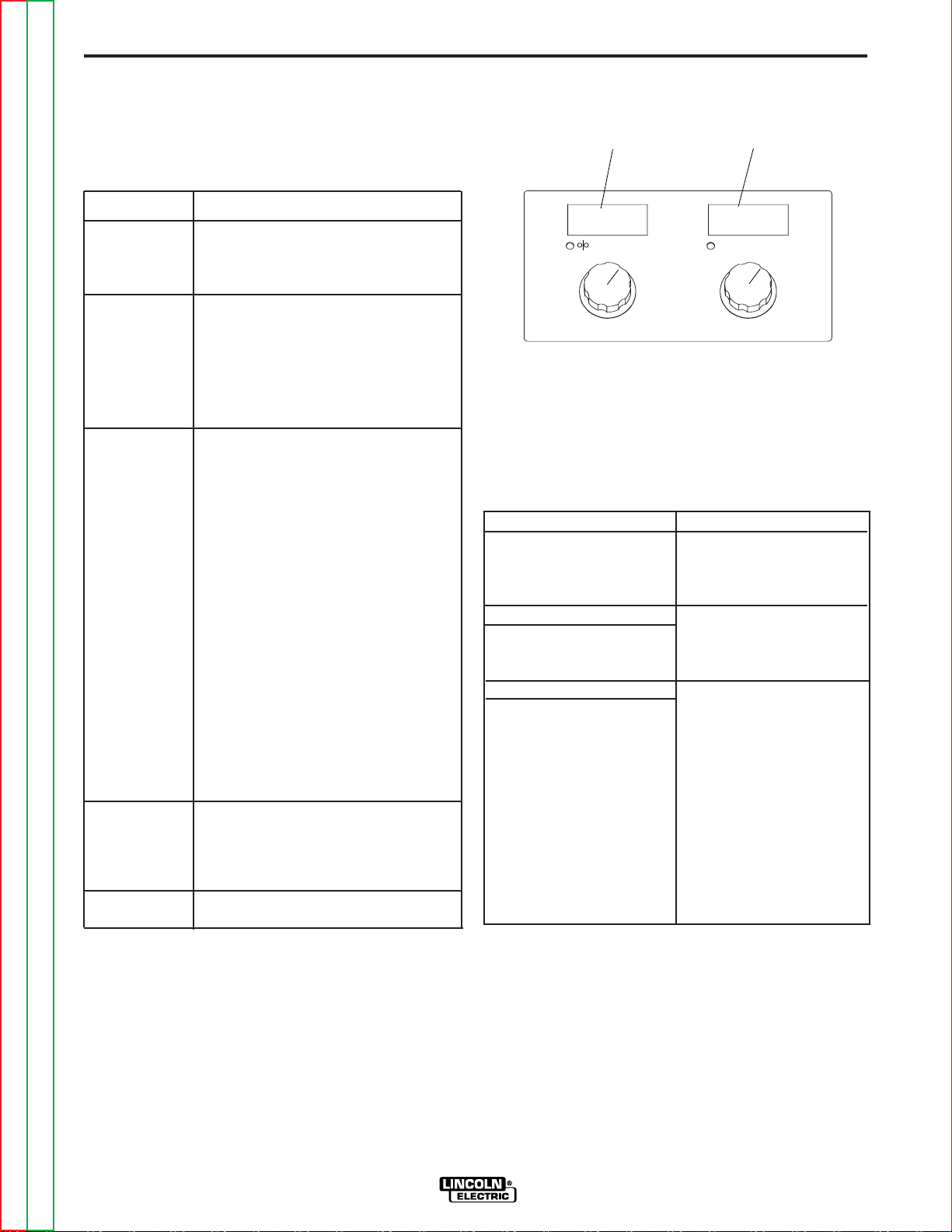
B-6 B-6
400
263
WFS AMPS
VOLTS TRIM
A
B
OPERATION
1. STATUS LED
The status LED indicates system status. Normal operation is a steady green light.
Note: During normal power-up, the LED may flash red
and/or green as the equipment performs self tests.
LED condition Definition
Steady green System okay. The power source and
wire feeder are communicating normally.
Blinking green Occurs during a reset and indicates
the power source is identifying each
component in the system. This is normal for the first 10 seconds after
power-up, or if the system configuration is changed during operation.
Alternating Non-recoverable system fault. If the
green and red power source or wire feeder status
LED is flashing any combination of red
and green, errors are present in the
system. Read the error code before
the machine is turned off.
Instructions for reading the error code
are detailed in the Service Manual.
Individual code digits are flashed in
red with a long pause between digits.
If more than one code is present, the
codes will be separated by a green
light.
To clear the error, turn the power
source OFF, and then back ON to
reset. See troubleshooting section.
Steady red Non recoverable hardware fault.
Generally indicates a problem with the
cables connecting the wire feeder to
the power source.
Blinking red Not applicable.
FIGURE B.2
A. WIRE FEED SPEED/AMMETER DISPLAY AND
OUTPUT KNOB
This meter displays either the wire feed speed or current value (Amps) depending upon welding process
(Mode) being used and the status of the wire feeder
and power source. Written below the display is "WFS"
and "Amps".
being displayed on the meter. The knob below the
meter adjusts the value displayed on the meters.
Prior to Welding Description
CV Welding Processes Meter displays the preset
CC Welding Processes Meter displays the preset
During Welding
An Weld Processes Meter displays displays
After Welding
An Weld Processes The meter holds the actual
An LED light illuminates which value is
WFS value.
Amps.
actual average welding
the
Amps.
current value for 5 seconds. The display blinks to
indicate the Power Feed
10M Single Wire Feeder is
in the "Hold" period. If the
output is adjusted while in
the "Hold" period, the
Power Feed 10M Single
Wire Feeder will revert to
the "Prior to welding" display described above.
2. DIGITAL METERS AND OUTPUT
ENCODER KNOBS
The primary weld procedure settings are controlled
and displayed using digital meters and output encoder
knobs located at the top of the Power Feed 10M Single
Wire Feeder control panel.
Return to Master TOC Return to Master TOC Return to Master TOC Return to Master TOC
Return to Section TOC Return to Section TOC Return to Section TOC Return to Section TOC
(See Figure B.2)
POWER FEED 10M SINGLE/DUAL
Note: If the output knob for the WFS/AMPS is adjusted while the Power Feed 10M Single Wire Feeder is in
the “Hold” period, the Power Feed 10M Single Wire
Feeder will immediately revert to the “Prior to Welding”
display
The default wire feed speed units are inches/minute and
can be changed to meters/minute by entering the "Set-up
Menu" in this Operation Section. The wire feed speed is
calibrated to within ±2%. Refer to the power source manual for calibration specifications of the ammeter.
.
Page 29

B-7 B-7
B. VOLTS / TRIM DISPLAYAND OUTPUT KNOB
The voltage/trim meter displays either the voltage or
trim value, depending upon the welding process
(mode) being used and the status of the wire feeder
and power source.
Below the meter are the words “Volts” and “Trim”. An
LED light illuminates to designate which value is being
displayed on the meter. The knob below the meter
adjusts the value displayed in the meter. The following
OPERATION
AFTER WELDING
Weld Process Volt/Trim Display
All Processes After welding, the meter holds the actual
average arc voltage for 5 seconds. During
this time, the display flashes to indicate
the wire feeder is in the "Hold" period.
Output adjustment while in the "Hold"
period results in the "prior to operation"
characteristics described above.
SYNERGIC CV VOLTAGE DISPLAY
tables describe the function of the Volts / Trim display
depending upon the status of the wire feeder / power
source package and the welding process utilized.
Synergic CV programs feature an ideal voltage best
suited for most procedures. Use this voltage as a starting point for the weld procedure and adjust if needed
PRIOR TO WELDING
Weld Process Volts / Trim Display prior to operation
for personal preferences.
The voltage is calibrated to ±2% over a range of 10 to
Nonsynergic CV Displays the preset Voltage value.
45 volts.
Synergic CV Displays the preset Voltage value.
Synergic Displays the preset Trim value from 0.50
CV-Pulse to 1.50, with 1.00 as the default. Trim
adjusts the arc length for Pulse programs.
Lower the trim value to decrease the arc
length, and raise the trim value to increase
the arc length. A trim value of 1.00 is optimum for most conditions.
Synergic CV-STT• Adjusts the background current of the
STT waveform. Used to modify the heat
input.
• Linc Net Power Sources: Displays the
background current as a value from 0.50
to 1.50, with 1.00 as the default. Lower
the trim value to decrease the heat input,
and raise the trim value to increase the
heat input. A trim value of 1.00 is optimum for most conditions.
• Arc Link Power Sources: Displays the
background current in amps. Lower the
background current to decrease the heat
input and raise the background current to
increase the heat input.
Nonsynergic Displays the preset CP value from 0 to 20.
Power The Power mode is best for thin sheet
metal and aluminum applications.
When the voltage knob is rotated, the display will show
an upper or lower bar indicating if the voltage is above
or below the ideal voltage.
• Preset voltage above ideal
voltage. (upper bar displayed)
• Preset voltage at ideal
voltage. (no bar displayed)
• Preset voltage below ideal
voltage. (lower bar displayed)
DURING WELDING
Weld Process Volts / Trim Display
All Processes Displays Actual
Average Arc
Return to Master TOC Return to Master TOC Return to Master TOC Return to Master TOC
Return to Section TOC Return to Section TOC Return to Section TOC Return to Section TOC
Voltage
POWER FEED 10M SINGLE/DUAL
Page 30

B-8 B-8
START OPTIONS
END OPTIONS
SET
SETUP
IR PORT
PULSE 4043 Ar
3/64"
ALUMINUM
72
WELD MODE
ARC CONTROL
OPERATION
OVERVIEW:
The MSP4 is the standard mode select panel for the
Power Feed 10M Single Wire Feeder wire feeders. The
MSP4 is capable of:
- Weld mode selection.
- Arc Control adjustment.
- Weld sequence control (Preflow Time, Run-in
WFS, etc.)
FIGURE B.3
1
6
2
7
3
8
4
9
5
10
3. MODE SELECT PANEL 4 (MSP4)
ITEM DESCRIPTION
1 IR (Infrared) Port.
2 Weld Mode Number.
3 Weld Wire Type.
4 Wire Size.
5 Weld Mode Description.
6
7 Selection Pushbutton Weld Mode or Arc
8
9
10 Status LED Lights-Start/End Options.
Status LED Lights-Weld Mode/Arc Control.
Control.
“Set” (Adjustment) Dial / Knob
Selection Pushbutton Start and End
Options.
• Limit setting for restricting the operators range of
control.
• Lockout to prevent unauthorized changes to
machine configuration.
Additionally , the MSP4 includes an infrared (IR) port for
wireless communication and configuration using a
Palm OS based hand held computer and a simplified
control layout.
LAYOUT-CONTROLS
(SEE FIGURE B.3)
The MSP4 panel controls (Items 7 and 9) set consist of
an encoder knob Item 8 and two push buttons. The
encoder is primarily used to change the value of the
selected attribute.
The left pushbutton (Item 7)
is used to toggle between
Weld Mode selection and any active Arc Controls
(a.k.a. wave controls). The choices of wave controls
varies by weld mode. For example, weld mode 31 has
one wave control, “Pinch”. Weld mode 110 has three
wave controls, “Peak Current”, “Background Current”
and “Tailout”. If the selected weld mode has no wave
controls, pressing the left pushbutton will have no
affect. If the selected weld mode uses one or more
wave controls, pressing the left pushbutton will
sequence the selection from weld mode -> wave control 1 (if active) -> wave control 2 (if active) -> wave
control 3 (if active) -> wave control 4 (if active) then
back to weld mode.
The right pushbutton (Item 9)
is used to select attributes that affect the available weld parameters such as
preflow time, burnback time, etc. Since most users will
require infrequent access to these attributes, they are
separate from weld mode selection and wave control
adjustment.
LAYOUT-DIGITAL DISPLAY
Return to Master TOC Return to Master TOC Return to Master TOC Return to Master TOC
Return to Section TOC Return to Section TOC Return to Section TOC Return to Section TOC
Through the use of alphanumeric displays, the MSP4
provides standard text messages designed to enhance
the user’s understanding of the machine’s operation as
well as provide advanced capabilities
The panel pro-
vides:
• Clear identification of the selected weld mode.
• Identification of weld modes not listed on the
preprinted weld mode list label.
• Control of up to four wave controls (arc controls.)
• Weld mode specific wave control name display
(Peak, Background, Pinch, etc.).
• Unit values are displayed (Amps, in/min, etc.).
• User-friendly machine setup and configuration.
POWER FEED 10M SINGLE/DUAL
The MSP4 display consists of a large 4-digit, 7-segment LED display, two 8-character alphanumeric LED
displays and one 16-character alphanumeric LED dis-
. The information shown on the various displays
play
depends on the state of the user interface as described
below.
When the MSP4 is being used to select a weld mode,
the 4-digit display (Item 2) indicates the selected weld
mode number. The upper 8-character alphanumeric
display (Item 3) indicates the electrode type (steel, aluminum, etc.) The lower 8-character alphanumeric display (Item 4) indicates the electrode size (.035", 1/16",
etc.).
Page 31

B-9 B-9
The 16-character alphanumeric display (Item 5) indicates the process type and other information, the exact
content of which depends on the selected weld mode.
This additional information may include specific electrode type (e.g. 4043) and/or a description of the recommended gas (e.g. HeArCO2).
When the MSP4 is being used to change the value of
an attribute, the 7-segment displays show the selected
attribute’s value. The upper 8-character alphanumeric
display is typically not used while changing an
attribute’s value. The lower 8-character alphanumeric
display is used to indicate the units of the selected
attribute (e.g. seconds, in/min, etc.). The 16-character
alphanumeric display is used to display the name of
the selected attribute.
The content of the displays while the user interface is
being used for advance machine configuration (e.g.
limit setting, pass code entering, machine setup, etc.)
is described in later sections.
POWER-UP SEQUENCE
When power is first applied to the machine, a lamp test
is performed. All discrete LED’
segment displays will show a pattern of "8." and all
alphanumeric displays will show a hatch pattern where
every-other pixel is illuminated. The lamp test will last
for two seconds, after which all displays are turned
back off. The 16-character alphanumeric display will
show "Initializing…" while waiting for the Weld
Sequencer to announce bus available. The MSP4
alphanumeric displays will then display the name of the
weld table loaded in the power source while the user
interface prepares the machine for operation. After all
initialization is complete, the MSP4 will display the
weld mode information for the mode number that was
selected when the machine was last powered down.
CHANGING WELD MODES
To select a weld mode, press the left MSP4 pushbutton until the WELD MODE LED is illuminated. Turn the
MSP4 encoder until the desired weld mode number is
displayed. As the MSP4 encoder knob is rotated, only
the weld mode number is displayed.
encoder idle time, the user interface will change to the
selected weld mode and the new mode’s electrode
type, electrode size and process information will
appear.
s are turned on, all 7-
After 1 second of
OPERATION
CHANGING ARC WAVE CONTROL
If the selected weld mode uses any of the four available
wave controls, users can press the left MSP4 pushbutton
until the ARC CONTROL
name and units (if applicable) of the available wave controls will appear. Note that the name of the control is
derived from the weld table and may not necessarily
appear as "Wave Control". Repeated pressing of the left
MSP4 pushbutton will cycle through all active wave controls and then the weld mode. Turning the MSP4 encoder
will change the value of the displayed wave control.
CHANGING WELD SEQUENCE BEHAVIOR
Weld sequencing attributes are grouped into two categories, STAR
OPTIONS may include Preflow Time, Run-in Wire Feed
Speed, and Start Time. END OPTIONS may include Spot
Timer, Crater Time, Burnback Time and Postflow Time.
The attributes that appear in the START and END
OPTIONS are weld mode dependent. For example, if a
TIG weld mode is selected, Run-in WFS will not appear
since it is not relevant to the selected process. Repeated
pressing of the right MSP4 pushbutton will cycle through
all relevant START and END OPTIONS. Turning the
MSP4 encoder will change the value of the selected
option.
When the Start Time attribute is set to a value other than
OFF, the START OPTIONS LED will blink synchronous
with the WFS and VOL TS/TRIM LED’son the dual-display
panel. This blinking is used to indicate that start wire feed
speed and voltage/trim can now be set to values different
from those used while welding. Similarly, if the Crater
Time attribute is set to a value other than OFF, the END
OPTIONS LED will blink synchronously with the dual-display LED’s, indicating that crater wire feed speed and
voltage/trim now can be set to values different from those
used while welding.
INFRARED (IR) CONTROL
The MSP4 interface includes an infrared transceiver. This
allows wireless machine configuration using a Palm OS
based hand held computer. A proprietary Palm OS application, W
(Contact Lincoln Electric for more information on this feature.)
LOCKOUT/SECURITY
LED is illuminated. The value,
T OPTIONS and END OPTIONS. START
eld Manager, was developed for this purpose.
The MSP4 can be optionally configured to prevent the
welder from changing selected user interface controls. By
default, all user interface controls can be changed. Weld
Manager software (for Palm OS or PC) must be used to
lock or unlock user unterface controls and to set a pass
code
Return to Master TOC Return to Master TOC Return to Master TOC Return to Master TOC
Return to Section TOC Return to Section TOC Return to Section TOC Return to Section TOC
POWER FEED 10M SINGLE/DUAL
Page 32

B-10 B-10
OPERATION
LIMIT SETTING
The MSP4 can be optionally configured to limit the operator’s
range of control of any weld parameter (weld WFS, arc control, etc.). Limits are only available with the Dual
Procedure/Memory Panel.
MACHINE SETUP/USER PREFERENCES
The MSP4 can be used to configure and troubleshoot the
machine.
ACCESSING THE MACHINE SETUP MENU
To access the Machine Setup menu, press both MSP4 push
buttons simultaneously.
display the first user preference, "P.0", and the SETUP LED
will illuminate.
• Pressing the left MSP4 pushbutton will exit the entire
Machine Setup menu while in the P.0 user preference.
• Turning the MSP4 encoder knob will select other available
User Preferences.
The MSP4 7-segment display will
SETUP FEATURES MENU
The Setup Menu gives access to the set-up configuration.
Stored in the setup configuration are user parameters that
generally need to be set only at installation. The parameters
are grouped as follows:
To access the setup menu, press the right and left buttons of
the MSP4 panel simultaneously. Note that the setup menu
cannot be accessed if the system is welding, or if there is a
fault (The status LED is not solid green).
Change the value of the blinking parameter rotating the SET
knob.
To exit the setup menu at any time, press the right and left
buttons of the MSP4 panel simultaneously. Alternately, 1
minute of inactivity will also exit the setup menu.
• P.1 through P.99 Unsecured Parameters (always
adjustable)
• P.101 through P.199 Diagnostic Parameters (always
read only)
• P.501 through P.599 Secured Parameters (accessible
only though a p.c. or palm application.)
• To exit the User Preference Menu, either rotate the MSP4
encoder until P.0 is displayed and press the left MSP4
pushbutton or press both MSP4 push buttons simultaneously at any time.
TABLE B.1
Unsecured Parameters
PARAMETER
P.0
P.1
P.2
P.3
P.4
P.5
P.6
P.7
P.8
P.9
P.11
P.12
P.13
P.80
P.99
Diagnostic Parameters
P.100
P.101
P.102
P.103
P.104
P.105
P.106
P.107
Return to Master TOC Return to Master TOC Return to Master TOC Return to Master TOC
Return to Section TOC Return to Section TOC Return to Section TOC Return to Section TOC
DESCRIPTION
Exit set-up menu
WFS Units
Arc Display Mode
Display Power
Trigger Memory Recall
Trigger Procedure Change
Stall Factor Adjustment
Gun Offset Adjustment
TIG Gas Control
Crater Delay
Set Timers
Travel Options
Adjust Arc Force
Sense From Studs
Show Test Modes
View Diagnostics
View Event Logs
View Fatal Logs
View Software Version
View Hardware Version
View Welding Software
View Ethernet IP Address
View Power Source Type
POWER FEED 10M SINGLE/DUAL
The following list includes all possible parameters in
ArcLink equipment. Not all of the parameters listed may
appear for your system. Refer to the (TABLE B.1) for
active parameters.
* PF= POWER FEED
PF*-10M (All Models)
√
√
√
√
√
√
√
√
√
√
√
√
√
√
√
√
√
√
√
√
√
PF*-10A
√
√
√
√
√
√
√
√
√
√
√
√
√
√
√
PF*-15M
√
√
√
√
√
√
√
√
√
√
√
Page 33

B-11 B-11
OPERATION
P
.0 Press the right button to exit the setup menu.
P.1 WFS units
Metric = m/min wire feed speed units
English = In/min wire feed speed units (default)
P.2 Arc Display Mode
Amps = The left display shows Amperage while welding.
(default)
WFS = The left display shows Wire Feed Speed while
welding.
P.3 Display Power
When P.3 is set to “Yes”, the power will be displayed on the
MSP4 while welding. When P.3 is set to”No”, power will not
be displayed.
P.4 Trigger Memory Recall
Enable = Selecting memories 2 through 6 with quick trigger pulls is enabled when the optional dual
procedure/memory panel is installed. To recall a memory
with the gun trigger, quickly pull and release the trigger the
number of times that correspond to the memory number.
For example, to recall memory 3, quickly pull and release
the trigger 3 times. Trigger memory recall can only be
performed when the system is not welding.
Disable = Memory selection is performed only by the buttons on the optional dual procedure/memory panel.
(default)
P.5 Procedure Change Method (Three Settings)
In order for any of these procedure change methods to
function, the "A-Gun-B" switch must be on the "Gun"
position.
1. "External Switch" (the default value), the machine will
only change the selected procedure when the procedure select digital input changes state.
2. "Quick Trigger" (the optional value 1), the machine will
only change the selected procedure when the trigger is
released and quickly re-pulled while welding in 2-step.
Enable=Allows switching between procedure A
cedure B while welding. The exception is that the procedure select digital input is no longer recognized.
3. "Integral Trigger Procedure" (the optional value 2),
the machine will only change the selected procedure
when the procedure select digital input changes state.
Machine operation is similar to the "External Switch"
selection except that additional logic prevents procedure
A from being re-selected when the trigger is quickly and
completely released at step 2 of the 4-step weld
sequence.
and pro-
the machine will always operate in 2-step if a weld is
made exclusively in procedure A, regardless of the 2/4
step switch position (this is intended to simplify tack welding when using a daul-schedule gun, such as the
Magnum 400 DS, while 4-step trigger is selected).
In order for any of these procedure change methods to
function, the “A-Gun-B” switch must be on the “Gun” position.
P.6 Push Pull Gun, Stall Factor Adjustment
The stall factor controls the stall torque of the push motor
when using a push-pull gun. The wire feeder is factory set
to not stall unless there is a large resistance to feeding
wire. The stall factor can be reduced to stall more easily
and possibly prevent bird nesting. However, low stall factors can cause motor stalling while welding which results
in the wire burning back to the tip.
If you are experiencing bird nests, check for other feeding
problems before adjusting the stall factor.
Default value for the stall factor is 75, with a range of 5 -
100.
To change the stall factor:
• Use the VOLTS/TRIM knob to adjust the stall factor.
Increasing the stall factor raises the motor torque and
decreasing the stall factor lowers the motor torque. Do
not increase the stall factor more than necessary. A high
stall factor may increase the occurrence of bird nesting
and a low stall factor may cause the wire to burn back to
the tip.
P.7 Push Pull Gun, Gun Offset Adjustment
The push-pull gun offset calibration adjusts the wire feed
speed calibration of the pull motor. The procedure should
only be performed when other possible corrections do not
solve the push-pull feeding problems. A rpm meter is
required to perform the pull gun motor offset calibration.
To perform the calibration procedure:
• Release the pressure arm on both the pull and push wire
drives.
• Set the wire feed speed to 200 ipm.
• Remove wire from the pull wire drive.
• Hold the rpm meter to the drive roll in the pull gun.
• Pull the trigger on the push-pull gun.
• Measure the rpm of the pull motor. The rpm should be
between 115 and 125 rpm. If necessary, decrease the
calibration setting to slow the pull motor, or increase the
calibration setting to speed up the motor. The calibration
range is -30 to +30, with 0 as the default value.
When setup parameter P
Return to Master TOC Return to Master TOC Return to Master TOC Return to Master TOC
Return to Section TOC Return to Section TOC Return to Section TOC Return to Section TOC
.5 is set to “Integral ProcTrig”,
POWER FEED 10M SINGLE/DUAL
Page 34

B-12 B-12
NOTES
P.8 TIG Gas Control (Two Settings)
1. "Valve (manual)", the internal solenoid will not
actuate while TIG welding, gas flow is manually
controlled by an external valve.
2. "Solenoid (auto)", the internal gas solenoid will
turn on and off automatically while
as follows:
• Preflow time will not be accessible from the MSP4.
• Postflow time will be available in the MSP4 "End
Options" and have a range of OFF to 10.0 seconds.
• The postflow time value is maintained when
switching between MIG and TIG modes.
• When machine output on/off is controlled via the
right encoder, gas flow will not start until the tungsten touches, the work piece, gas flow will stop
after the postflow time when the arc is broken.
• When machine output on/off is controlled via an
arc start switch or foot Amptrol, gas will begin flowing when the output is turned on and stop flowing
after the postflow period after the output is turned
off.
P.9 Crater Delay
This parameter enables a timer delay for each feed
head to bypass the Crater option when short tack
welds are desired. If the trigger is released before
the timer expires, Crater will be bypassed and the
weld will end. If the trigger is released after the timer
expires, Crater will function as normal (if Crater
function is turned on).
TIG welding
P.13 Adjust Arc Force
Use this menu to adjust Arc Force values for Start,
Weld and Crater. Press the right MSP4 button to
enter the menu and rotate the knob to choose either
Start, Weld or Crater. Press the right MSP4 button
and then rotate the knob to the desired value.
Press the left MSP4 button to set the value and exit.
Continue to adjust Arc Force for other states, and
then press the left MSP4 button to exit the menu.
P.80 Sense From Studs (two settings)
1. "False", the voltage sense lead is automatically
selected based on the DIP switch configuration
and the selected weld mode.
value that is used every time the machine is powered up. Note that setting P.80 to "False" does
not preclude voltage sensing from the studs if
studs sensing is specified by the selected weld
mode (for example stick and TIG weld modes will
still sense voltage at the studs).
rue", voltage sensing is forced to "studs"
2. "T
regardless of the DIP switch configuration and
selected weld mode. Setting P.80 to "T
should only be done for troubleshooting purposes. P.80 will automatically be set back to "False"
the next time the equipment is powered up or can
be manually changed back to "False" via the
setup menu.
This is the default
rue"
P.11 Set Timers
This menu is used to adjust timer values for
Upslope, Downslope and Restrike. Press the right
button to enter the Set Timer menu. Rotate the
knob to select the timer to adjust and then press the
right button. Adjust the value of the timer by rotating
the knob. Press the left MSP4 button to set the
value and exit. Continue to adjust other timers as
necessary, and then press the left button to exit the
Set Timer menu.
P.12 Travel Options
This menu is used to change the travel options for a
travel carriage, including starting and ending functions. The right MSP4 button to enter the Travel
Options menu and rotate the encoder to select
either starting or ending options. Press the right
MSP4 button to select the option. Press the left
MSP4 button to set the value and exit. Rotate the
encoder to select other options, or press the left
MSP4 button to exit the menu.
In order to control the welding arc, the power source
continually monitors arc current and arc voltage.
Arc current is measured internal to the power
source.
• Voltage internal to the power source ("studs")
• V
• Voltage at a user-wired sense lead ("21" lead)
Remote voltage sensing (anything other than
"studs") is used to obtain a more accurate voltage
measurement since the sense lead is closer to the
arc. Remote voltage sensing can involve external
wiring and DIP switch configuration, there is a
potential for incorrect voltage measurement which
can lead to poor arc control or wire burn back.
P.99 Show Test Modes
Many weld tables include special modes for testing
and servicing the welding system. Set this parameter to YES to show all test modes.
When the power source is turned off, the Show Test
Modes parameter automatically reverts back to
"NO".
Arc voltage can be measured as follows:
oltage at the wire feeder ("67" lead)
Return to Master TOC Return to Master TOC Return to Master TOC Return to Master TOC
Return to Section TOC Return to Section TOC Return to Section TOC Return to Section TOC
POWER FEED 10M SINGLE/DUAL
Page 35

B-13 B-13
C
OLD FEED
GAS PURGE
2-STEP
4 STEP
OPERATION
P.100 View Diagnostics
Diagnostics are only used for servicing the
Power Wave system.
Yes = Shows P.101 through P.500 in the
SETUP menu.
No = Only P.0 through P.100 are shown in the
SETUP menu.
P.101 Event Logs
Press the right MSP4 button to view the Event
Logs. Rotate the encoder to select the object
to read and then press the right MSP4 button.
Various software information will appear about
key system events. Press the left MSP4 button to exit.
P.102 Fatal Logs
Press the right MSP4 button to view the Fatal
Logs. Rotate the encoder to select the module
to read and then press the right MSP4 button.
Various software information will appear about
critical module actions. Press the left MSP4
button to exit.
P.103 Software Version
Press the right MSP4 button to view the software loaded into each module (p.c. board).
Rotate the encoder to select the module to
read and then press the right MSP4 button.
The panel will display the main software version loaded into the module. Press the left
MSP4 button to exit.
P.104 Hardware Version
Press the right MSP4 button to view the hardware version of each module (p.c. board).
Rotate the encoder to select the module to
read and then press the right MSP4 button.
The panel will display the main hardware version loaded into the module. Press the left
MSP4 button to exit.
P.105 Welding Software
Press the right MSP4 button to view the welding software version inside the power source.
Press the left MSP4 button to exit.
4. COLD FEED / GAS PURGE SWITCH
Cold Feed and Gas Purge are combined
into a two position momentary toggle
switch.
To activate Cold Feeding, hold the switch
in the UP position. The wire drive will feed
electrode but neither the power source nor
the gas solenoid will be energized.
Keeping the electrode and gun electrically
“cold”. Adjust the speed of cold feeding by
rotating the WFS knob.
• This feature is useful for threading the electrode
through the gun.
• While the “cold feed” circuit is activated, adjust the wire
feed speed using the WFS knob.
Hold with toggle switch in the DOWN position to activate
Gas Purge
noid valve will energize but neither the power source output nor the drive motor will be turned on. The Gas Purge
switch is useful for setting the proper flow rate of shielding gas. Flow meters should always be adjusted while the
shielding gas is flowing.
and let the shielding gas flow. The gas sole-
5. 2-STEP / 4-STEP TRIGGER SWITCH
The 2-Step / 4-Step switch has two set
positions. Place the switch in the UP position for 2-step Trigger Operation and in the
down position for 4-step Trigger
Operation.
2 Step Trigger
2 Step trigger operation is the most com
mon. When the gun trigger is pulled, the
welding system (power source and wire
feeder) cycles through the arc starting
sequence and into the main welding parameters. The welding system will continue
to weld as long as the gun trigger is activated. Once the
trigger is released, the welding system cycles through the
arc ending steps.
-
Return to Master TOC Return to Master TOC Return to Master TOC Return to Master TOC
Return to Section TOC Return to Section TOC Return to Section TOC Return to Section TOC
P.106 Ethernet IPAddress
Press the right MSP4 button to view the IP
address of the Ethernet board. If no Ethernet
Board is installed, the display shows "No Enet
Found." Press the left MSP4 button to exit.
P.107 Power Source
Press the right MSP4 button to view the type of
power source connected to the control box.
Press the left MSP4 button to exit.
4-Step Trigger Operation
When the switch is in the 4-Step position the Power Feed
10M Single Wire Feeder provides trigger interlock capability (the operator can release the trigger and the system
will continue to weld) and it also allows the operator to
control the amount of time spent in the start and crater
weld modes.
See Sequence of Operation for more information on the
overall interaction trigger switch with the weld sequence.
The 2-Step / 4-Step trigger has no effect when welding
with SMA
W or CAG procedures.
POWER FEED 10M SINGLE/DUAL
Page 36

POWER FEED 10M SINGLE/DUAL
OPERATION
B-14 B-14
Return to Section TOC Return to Section TOC Return to Section TOC Return to Section TOC
Return to Master TOC Return to Master TOC Return to Master TOC Return to Master TOC
Head / Procedure Select
• Press toselect head or change ac tive
procedure.
• Changes to weld settings affect
active procedure only.
Memory
• Permanent storage for procedure
settings.
• Six available m e morylocations. One
procedure (A or B) can be stored in
each.
PRESS AND HOLD TO SAVE
MEMORY
FIGURE B.4
2 STEP TRIGGER OPERATION
(See Figure B.4)
Sometimes it is advantageous to set specific arc start,
crater and arc ending parameters for the ideal weld.
Many times when welding aluminum crater control is
necessary to make a good weld. This is done by setting Start, Crater and Burnback functions to desired
values.
SEQUENCE OF OPERATION
Following is the total weld sequence that the Power
Feed 10M Single Wire Feeder will execute. If any parameter is inactive or its time is set to zero, the weld procedure immediately shifts to the next parameter in the
sequence.
1. PREFLOW: Shielding gas begins to flow immediately when the gun trigger is pulled.
2. STRIKE: After preflow time expires, the power
source regulates to the start output and wire is
advanced towards the work piece at the Strike WFS.
If an arc is not established within 1.5 seconds, the
power source output and wire feed speed skips to
the weld settings.
3. UPSLOPE: Once the wire touches the work and an
arc is established, both the machine output and the
wire feed speed ramp to the weld settings throughout the start time. The time period of ramping from
the start settings to the weld settings is called UPSLOPE.
4. WELD: After upslope, the power source output and
the wire feed speed continue at the weld settings.
5. CRATER: As soon as the trigger is released, the
wire feed speed and power source output ramp to
the crater settings throughout the crater time. The
time period of ramping from the weld settings to the
crater settings is called DOWNSLOPE.
6. BURNBACK: After the crater time expires, the wire
feed speed is turned OFF and the machine output
continues for the burnback time.
7. POSTFLOW: Next, the machine output is turned
OFF and shielding gas continues until the post flow
timer expires.
Page 37

B-15 B-15
SShihieellddiingng
GaGass
IdleIdle PreflowPreflow
StrikeStrike
UpslopeUpslope
WWeldeld
BurnbackBurnback PostflowPostflow
IdleIdle
WFSWFS
OOnn
OOffff
SSttrriikkee
OOffff
WWeleldd
OOffff
WWeleldd
ArcArc EstablishedEstablished
TTriggerrigger
PulledPulled
TTriggerrigger
ReleasedReleased
1.5 sec1.5 sec
Max.Max.
BurnbackBurnback
TTimeime
SSttaarrtt
DownslopeDownslope
CCrrataterer
PPoweowerr
SSouourrccee
OutOutpputut
CCrrataterer
StartStart
TTriggerrigger PulledPulled
CraterCrater
TTriggerrigger ReleasedReleased
SSttarartt
22
11
33 44
55
66 77
88
99
OPERATION
4 STEP TRIGGER OPERATION
(See Figure B.5)
The 4 step trigger sequence gives the most flexibility
when the Start, Crater and Burnback functions are
active. This is a popular choice when welding aluminum because extra heat may be needed during Start
and less heat desired during Crater. With 4 step trigger, the welder chooses the amount of time to weld at
the Start, Weld and Crater settings by using the gun
trigger. Burnback reduces the likelihood of wire to
sticking in the weld pool at the end of a weld and also
prepares the end of the wire for the next arc start.
SEQUENCE OF OPERATION
Following is the total weld sequence that the Power
Feed 10M Single Wire Feeder will execute. If any parameter is inactive or its time is set to zero, the weld procedure immediately shifts to the next parameter in the
sequence.
1. PREFLOW
ly when the gun trigger is pulled.
2. STRIKE: After preflow time expires, the power
source regulates to the start output and wire is
advanced towards the work piece at the Strike WFS.
If an arc is not established within 1.5 seconds, the
power source output and wire feed speed skips to
the weld settings.
: Shielding gas begins to flow immediate-
FIGURE B.5
3. START: The power source welds at the “Start” WFS
and voltage until the trigger is released.
4. UPSLOPE: Once the trigger is released, both the
machine output and the wire feed speed ramp up or
down to the weld settings throughout the start time.
The time period of ramping from the Start settings to
the Weld settings is called UPSLOPE.
5. WELD: After Upslope, the power source output and
the wire feed speed continue at the Weld settings.
6. DOWNSLOPE: Then as soon as the trigger is
pulled, the wire feed speed and power source output
ramp to the crater settings during the crater time.
The time period of ramping from the weld settings to
the crater settings is called DOWNSLOPE.
7. CRATER: Alter the Downslope time expires, the
machine welds at the Crater WFS and voltage settings until ether the trigger is released or the Crater
time expires.
8. BURNBACK: After the crater time expires, the wire
feed speed is turned OFF and the machine output
continues for the burnback time.
9. POSTFLOW: Next, the machine output is turned
OFF and shielding gas continues to flow until the
post flow timer expires.
Return to Section TOC Return to Section TOC Return to Section TOC Return to Section TOC
Return to Master TOC Return to Master TOC Return to Master TOC Return to Master TOC
POWER FEED 10M SINGLE/DUAL
Page 38

B-16 B-16
OPERATION
PROCESS SETUP AND OPERATION
The Power Feed/Power Wave system delivers world
class arc performance for a wide variety of processes.
Using the foundation of Waveform Control
Technology™, each weld mode is precisely tuned to
meet exacting standards for low spatter, weld bead
profile and arc shape.
Customized welding software means even the most
difficult materials can by welded with the Power
Feed/Power Wave system. Copper, Nickel, Silicon
Bronze are just a few of the unusual alloys the Power
Feed system welds with ease when special software is
loaded.
FIGURE B.6
Figure B.6 below shows a list of weld modes common
on many Power Wave power sources. This table is
found on the inside front panel door of the Power Feed
10M Single Wire Feeder. The specific list of available
weld modes depends upon the power source connected to the Power Feed 10M Single Wire Feeder wire
feeder.
CC - Stick Mode
CC - TIG
CC - Gouge
CV - Non Synergic
CV - Synergic
CV - Pulse
CV - Pulse on Pulse
CV - STT
Non- Synergic
Modes
Return to Master TOC Return to Master TOC Return to Master TOC Return to Master TOC
Return to Section TOC Return to Section TOC Return to Section TOC Return to Section TOC
POWER FEED 10M SINGLE/DUAL
Synergic Modes
Page 39

B-17 B-17
Trim .50
Arc Length Short
Trim 1.00
Arc Length Medium
Trim 1.50
Arc Length Long
Arc Control OFF
Medium Frequency and Width
Arc Contro l +10.0
High Frequency , Foc used
Arc Control -10.0
Low Frequency, Wide
OPERATION
STEEL AND STAINLESS SYNERGIC GMAW-P (PULSED MIG) WELDING
Synergic GMAW-P (Pulsed MIG) welding is ideal for low spatter, out of position and reduced heat input applications. During pulse welding, the welding current continuously switches from a low level to a high level and then
back again. Each pulse sends a small droplet of molten metal from the wire to the weld puddle.
Pulse welding controls the arc length with 'Trim' instead of voltage. When trim (arc length) is adjusted, the Power
Wave automatically recalculates the voltage, current and time of each part of the pulse waveform for the best result.
Trim adjusts the arc length and ranges from 0.50 to 1.50, with a nominal value of 1.00 for a 3/4" (19mm) electrode
stick-out. Trim values greater than 1.00 increase the arc length, while values less than 1.00 decrease the arc
length.
FIGURE B.7a
ARC CONTROL
For steel and stainless pulse modes, Arc Control regulates the focus or shape of the arc. Arc Control values greater
than 0.0 increase the pulse frequency while decreasing the background current, resulting in a tight, stiff arc best
for high speed sheet metal welding. Arc Control values less than 0.0 decrease the pulse frequency while increasing the background current, for a soft arc good for out-of-position welding.
FIGURE B.7b
Return to Master TOC Return to Master TOC Return to Master TOC Return to Master TOC
Return to Section TOC Return to Section TOC Return to Section TOC Return to Section TOC
POWER FEED 10M SINGLE/DUAL
Page 40

B-18 B-18
OPERATION
ALUMINUM SYNERGIC GMAW-P (PULSED
MIG)AND GMAW-PP (PULSE ON PULSE)
WELDING
The Power Feed 10M Single Wire Feeder and Power
Wave welding power source combine to readily produce top quality aluminum welds with excellent
appearance, little spatter and good bead shape. Pushpull guns are available for consistent feeding when
welding a long distance away from the wire feeder.
Pulse-on-Pulse Welding
The Power Wave system offers both traditional pulse
and Pulse-on-Pulse™. Pulse-on-Pulse (GMAW
an exclusive waveform for aluminum welding. Use it to
make welds with a "stacked dime" appearance, similar
to GTAW welds.
FIGURE B.7c
-PP) is
FIGURE B.7e
Frequency Modulation = 10
Narrow weld and ripple spacing, fast travel speed.
The pulsing frequency is adjustable. Changing the frequency modulation (or arc control) of the waveform
changes the ripple spacing. Faster travel speeds may
be achieved by using higher values of frequency modulation.
FIGURE B.7d
Frequency Modulation = -10
Wide weld and ripple spacing, slow travel speed.
Return to Master TOC Return to Master TOC Return to Master TOC Return to Master TOC
Return to Section TOC Return to Section TOC Return to Section TOC Return to Section TOC
POWER FEED 10M SINGLE/DUAL
Page 41

B-19 B-19
194
0
WFS AMPS
VOLTS TRIM
LESS
AMPS
MORE
AMPS
OUTPUT
OFF
OUTPUT
ON
OPERATION
MACHINE FUNCTIONALITY BY WELD PROCESS
CC-STICK
Use the following tables to review how the machine functions (output controls, arc control, Start options and weld
options) for the weld modes listed in the top table.
CC STICK MODES
Material
PROCESS
MODE
ARC CONTROL
ARC FORCE
(Soft)-10.0 to
(Crisp)+10.0
Steel
Steel
Stick Soft(7018)
Stick Crisp(6010)
OUTPUT CONTROL KNOBS
DESCRIPTION
Arc Force adjusts the short circuit current for a soft arc, or for
a forceful, driving arc. It helps to
prevent sticking and shorting
organic coated electrodes, particularity globular transfer types
such as stainless and low
hydrogen. Arc Force is especially effective for root pass on
pipe with stainless electrode
and helps to minimize spatter
for certain electrodes and procedure as with low hydrogen,
etc.
1
2
START OPTIONS
START TIME:
0 to 10 seconds
If no remote control is installed,
FUNCTION
this control sets the time for the
weld output to ramp up or down
from a preset Start current to
the preset Weld current. Use
the WFS/AMP knob to adjust
Start current while the Start
Options LED is displayed.
END OPTIONS
No arc ending options are active for SMAW (Stick)
welding modes.
Return to Master TOC Return to Master TOC Return to Master TOC Return to Master TOC
Return to Section TOC Return to Section TOC Return to Section TOC Return to Section TOC
POWER FEED 10M SINGLE/DUAL
Page 42

B-20 B-20
300
25.3
WFS AMPS
V
OLTS TRIM
LESS
W
FS
MORE
W
FS
LESS
VOLTS
MORE
VOLTS
200
2.0
WFS AMPS
V
OLTS TRIM
L
ESS
W
FS
M
ORE
W
FS
S
HORTER
ARC
L
ONGER
A
RC
OPERATION
MACHINE FUNCTIONALITY BY WELD PROCESS
CV GMAW/FCAW (NON-SYNERGIC)
Use the following tables to review how the machine functions (output controls, arc control, Start options and weld
options) for the weld modes listed in the top table.
CV NON-SYNERGIC MODES
Material
PROCESS
WELD MODE
Steel
Steel
GMAW, POWER MODE
Steel
OUTPUT CONTROL KNOBS, WELD MODE 5 & 6
ARC CONTROL
EFFECT / RANGE
(Soft)-10.0 to
(Crisp)+10.0
Arc Force adjusts the short circuit current for a soft arc, or for
DESCRIPTION
a forceful, digging arc.
GMAW, CV
FCAW, CV
OUTPUT CONTROL KNOBS, WELD MODE 40
END OPTIONS
EFFECT / RANGE
Postflow Time
0 to 10 seconds
5
40
6
DESCRIPTION
Adjusts the time that shielding
gas flows after the welding output turns off.
START OPTIONS
The start Options available in these Non-Synergic CV
weld modes, their adjustment range and function are as
follows:
EFFECT / RANGE
DESCRIPTION
Crater Procedure
(0 TO 10.0 SECONDS)
Crater Procedure controls the
WFS and Volts for a specified
time at the end of the weld after
the trigger is released. During
the Crater time, the machine
will ramp up or down from the
Weld Procedure to the Crater
Preflow Time
0 - 10 seconds
Run-In WFS:
Off, 50 to150 in/min.
Start Procedure
0 - 10 seconds
Adjusts the time the gas flows
after the trigger is pulled and
prior to feeding.
Run-In sets the wire feed
speed from the time the trigger
is pulled until an arc is established.
The Start Procedure controls
the WFS and Volts for a specified time at the beginning of the
weld. During the start time, the
machine will ramp up or down
from the Start Procedure to the
Burnback:
0 to .25 Seconds
Spot Timer:
0 to 10 Seconds
Procedure.
The burnback time is the
amount of time that the weld
output continues after the wire
stops feeding. It prevents the
wire from sticking in the puddle
and prepares the end of the
wire for the next arc start.
Adjusts the time welding will
continue even if tigger is still
pulled. This option has no ef fect
in 4-Step Trigger Mode.
preset Welding Procedure.
Return to Master TOC Return to Master TOC Return to Master TOC Return to Master TOC
Return to Section TOC Return to Section TOC Return to Section TOC Return to Section TOC
POWER FEED 10M SINGLE/DUAL
Page 43

B-21 B-21
200
26.3
WFS AMPS
VOLTS TRIM
LESS
WFS
MORE
WFS
LESS
V
OLTS
MORE
V
OLTS
OPERATION
MACHINE FUNCTIONALITY BY WELD PROCESS
GMAW (SYNERGIC)
Use the following tables to review how the machine functions (output controls, arc control, Start options and weld
options) for the weld modes listed in the top table.
SYNERGIC CV MODES
MATERIAL
Steel
Steel
Stainless
Stainless
Aluminum 4043
Aluminum 5356
Metal Core
PROCESS
GMAW
GMAW
W
GMA
GMAW
TIG
TIG
GMAW
OUTPUT CONTROL KNOBS
GAS
CO
2
Ar(Mix)
Ar(Mix)
Ar/He/CO
Ar
Ar
Ar/CO
2
WIRE SIZE
0.030 0.035 0.045 0.052
--- 10 20 24
94 11 21 25
61 31 41 ---
2
63 33 43 ---
--- 148 71 ---
--- 151 75 ---
--- --- --- ---
ARC CONTROL
EFFECT / RANGE
PINCH EFFECT
(-10.0 to +10.0)
Adjust the short circuit current
to create a soft arc, or a force-
DESCRIPTION
ful, digging arc.
START OPTIONS
The start Options available in these synergic CV weld
modes, their adjustment range and function are as
follows:
EFFECT / RANGE
Preflow Time
0 - 10 seconds
Adjusts the time the gas flows
after the trigger is pulled and
DESCRIPTION
prior to feeding.
Run-in WFS:
Off, 50 to150 in/min.
Run-In sets the wire feed
speed from the time the trigger
is pulled until an arc is estab-
lished.
Start Procedure
The Start Procedure controls
the WFS. Trim at a specified
time at the beginning of the
weld. During the start time, the
machine will ramp up or down
from the Start Procedure to the
preset Welding Procedure.
END OPTIONS
EFFECT / RANGE
Postflow Time
0 to 10 seconds
Burnback:
0 to .25 Seconds
Crater Procedure
DESCRIPTION
Adjusts the time that shielding
gas flows after the welding output turns off.
The burnback time is the
amount of time that the weld
output continues after the wire
stops feeding. It prevents the
wire from sticking in the puddle
and prepares the end of the
wire for the next arc start.
Crater Procedure controls the
WFS and volts for a specified
time at the end of the weld after
the trigger is released. During
the Crater time, the machine
will ramp up or down from the
Weld Procedure to the Crater
Procedure.
Return to Master TOC Return to Master TOC Return to Master TOC Return to Master TOC
Return to Section TOC Return to Section TOC Return to Section TOC Return to Section TOC
POWER FEED 10M SINGLE/DUAL
Page 44

B-22 B-22
WFS AMPS
V
OLTS TRIM
LESS
WFS
MORE
WFS
L
ESS
T
RIM
M
ORE
T
RIM
OPERATION
MACHINE FUNCTIONALITY BY WELD PROCESS
PULSE AND PULSE-ON-PULSE (SYNERGIC)
Use the following tables to review how the machine functions (output controls, arc control, Start options and weld
options) for the weld modes listed in the top table.
PULSE AND PULSE-0N-PULSE MODES
MATERIAL
ALUMINUM 4043
ALUMINUM 4043
ALUMINUM 5356
ALUMINUM 5356
PROCESS
Pulse
Pulse-on-Pulse
Pulse
Pulse-on-Pulse
OUTPUT CONTROL KNOBS
GAS
Ar
Ar
Ar
Ar
WIRE SIZE
0.035 3/64 1/16
149 72 74
98 99 100
152 76 78
101 102 103
ARC CONTROL
PULSE
DESCRIPTION
FREQUENCY:
(Low)-10.0 to
(High)+10.0
For Pulse modes, Arc Control
changes the pulsing frequency.
END OPTIONS
EFFECT / RANGE
FUNCTION
When the frequency changes,
the Power Wave system automatically adjusts the background current to maintain a
similar heat input into the weld.
Low frequencies give more control over the puddle and high frequencies minimize spatter.
Postflow Time:
0 to 10 seconds
Burnback: 0 to .25
Seconds
Adjusts the time that shielding
gas flows after the welding output turns off.
The burnback time is the
amount of time that the weld
output continues after the wire
stops feeding. It prevents the
wire from sticking in the puddle
START OPTIONS
PREFLOW TIME
0 - 10 seconds
RUN-IN WFS:
Off, 50 to150 in/min.
DESCRIPTION
Crater Procedure
Adjusts the time the gas flows
after the trigger is pulled and
prior to feeding wire.
Run-in sets the wire feed speed
from the time the trigger is
pulled until an arc is estab-
and prepares the end of the
wire for the next arc start.
Crater Procedure controls the
WFS and volts for a specified
time at the end of the weld after
the trigger is released. During
the Crater time, the machine
will ramp up or down from the
Weld Procedure to the Crater
Procedure.
lished.
Start Procedure
The Start Procedure controls
the WFS. Trim at a specified
time at the beginning of the
weld. During the start time, the
Spot Timer:
0 to 10 Seconds
Adjusts the time welding will
continue even if tigger is still
pulled. This option has no ef fect
in 4-Step Trigger Mode.
machine will ramp up or down
from the Start Procedure to the
Return to Master TOC Return to Master TOC Return to Master TOC Return to Master TOC
Return to Section TOC Return to Section TOC Return to Section TOC Return to Section TOC
preset Welding Procedure.
POWER FEED 10M SINGLE/DUAL
Page 45

B-23 B-23
200
----
WFS AMPS
V
OLTS TRIM
LESS
D
EPOSITION
MORE
D
EPOSITION
OPERATION
MACHINE FUNCTIONALITY BY WELD PROCESS
STT AND STT II (SYNERGIC)
Use the following tables to review how the machine functions (output controls, arc control, Start options and weld
options) for the weld modes listed in the top table.
STT AND STT II MODES
MATERIAL
STEEL
STAINLESS
PROCESS
STT
GAS
Ar/CO
CO
WIRE SIZE
0.035 0.045 0.052
2
2
109 125 125
STEEL
AINLESS
ST
STT II
Ar/CO
CO
2
2
110 126 126
OUTPUT CONTROL KNOBS (There is no Voltage control when STT welding.)
START OPTIONS
PREFLOW TIME
0 - 10 seconds
RUN-IN WFS:
Off, 50 to150 in/min.
EFFECT / RANGE
PEAK CURRENT
Peak Current acts similar to an
DESCRIPTION
Start Procedure
arc pinch control. Peak Current
sets the arc length and promotes good fusion. Higher
peak current levels will cause
the arc to broaden momentarily
while increasing arc length. If
set too high, globular transfer
may occur. Setting it too low
may cause instability and wire
stubbing. Best practice is to
adjust for minimum spatter and
END OPTIONS
PARAMETER RANGE
Postflow Time:
0 to 10 seconds
puddle agitation.
BACKGROUND
CURRENT
Background Current controls
the overall heat input in the
Crater Procedure
weld. High background currents flatten the weld bead, and
low background currents create
a taller rounded contour.
FUNCTION
Adjusts the time the gas flows
after the trigger is pulled and
prior to feeding wire.
Run-in sets the wire feed speed
from the time the trigger is
pulled until an arc is established.
The Start Procedure controls
the WFS. Trim at a specified
time at the beginning of the
weld. During the start time, the
machine will ramp up or down
from the Start Procedure to the
preset Welding Procedure.
FUNCTION
Adjusts the time that shielding gas
flows after the welding output turns
off.
Crater Procedure controls the
WFS and volts for a specified time
at the end of the weld after the trigger is released. During the Crater
time, the machine will ramp up or
down from the Weld Procedure to
the Crater Procedure.
TAIL OUT
(STT ll MODES
ONLY)
Tail out provides additional
power without the molten
droplet becoming too large.
Burnback:
0 to .25 Seconds
Increase as necessary to add
heat input without increasing
arc length. Often this results in
faster travel speeds. Note that
as tail out increases, the peak
Return to Master TOC Return to Master TOC Return to Master TOC Return to Master TOC
Return to Section TOC Return to Section TOC Return to Section TOC Return to Section TOC
current and/or background current may need to be reduced.
POWER FEED 10M SINGLE/DUAL
Spot Timer:
0 to 10 Seconds
The burnback time is the amount of
time that the weld output continues
after the wire stops feeding. It prevents the wire from sticking in the
puddle and prepares the end of the
wire for the next arc start.
Adjusts the time welding will continue even if tigger is still pulled.
This option has no effect in 4-Step
Trigger Mode.
Page 46

B-24 B-24
120
OFF
WFS AMPS
VOLTS TRIM
Maximum
Amperage
Output
Control
OPERATION
MACHINE FUNCTIONALITY BY WELD PROCESS
GTAW (Touch Start TIG) Welding
Use the following tables to review how the machine functions (output controls, arc control, Start options and weld
options) for the weld modes listed in the top table.
TOUCH START TIG
Material
PROCESS
MODE
All Metals
ARC CONTROL
Touch Start TIG
3
OUTPUT CONTROL KNOBS
No Arc Controls are active for Touch Start TIG.
START OPTIONS
START PROCEDURE:
The Start Procedure controls the Amperage at a
fixed level for the set amount of time.
END OPTIONS
No Arc ending options are active for Touch Start TIG.
GTAW (TIG) WELDING
The Power Feed / PowerWave system is excellent for Touch Start TIG welding.
The system supports both TIG torches with or without gas control valves. TIG torches with gas control valves con-
nect directly to the gas flow regulator. For TIG torches without gas control valves, connect the output gas hose on
the Power Feed 10M Single Wire Feeder.
Touch Start TIG
Weld Sequence
TIG torches without
built-in Gas Valves
No Foot/Hand Amptrol
1. Adjust the arc amperage with the left knob
on the display panel.
2. Turn the right knob on the display panel
until the Output Control is ON. Gas will
start to flow.
3. Touch the tungsten to the work piece.
4. Lift the tungsten to create an arc and weld.
5. Stop welding by turning the Output Control
to OFF, or by pulling away the tungsten
from the work.
6. Gas flow will continue for a short time and
then shut-off.
1. Adjust the maximum arc amperage with
the left knob on the display panel.
2. Touch the tungsten to the work piece.
3. Press the foot pedal or slide the hand amptrol a slight amount. Gas will start to flow.
4. Lift the tungsten to create an arc.
5. Regulate the arc current with the foot pedal
or hand amptrol.
6. Stop welding by releasing the foot pedal or
hand amptrol, or by pulling the tungsten
away from the work.
7. Gas will continue for a short time and then
shut-off.
With Foot/Hand Amptrol
1. Adjust the maximum arc amperage with
the left knob on the display panel.
2. Touch the tungsten to the work piece.
3. Press the foot pedal or slide the hand amptrol a slight amount.
4. Open the gas valve on the TIG torch.
5. Lift the tungsten to create an arc.
6. Regulate the arc current with the foot pedal
or hand amptrol.
7. Stop welding by releasing the foot pedal or
hand amptrol, or by pulling the tungsten
TIG torches with
built-in Gas Valves
1. Adjust the arc amperage with the left knob
on the display panel.
2. Turn the right knob on the display panel
until the Output Control is ON.
3. Open the gas valve on the TIG torch.
4. Touch the tungsten to the work piece.
5. Lift the tungsten to create an arc and weld.
6. Stop welding by turning the Output Control
to OFF, or by pulling away the tungsten
from the work.
7. Close the gas valve on the TIG torch.
away from the work.
Return to Master TOC Return to Master TOC Return to Master TOC Return to Master TOC
Return to Section TOC Return to Section TOC Return to Section TOC Return to Section TOC
POWER FEED 10M SINGLE/DUAL
8. Close the gas valve on the TIG torch.
Page 47

B-25 B-25
HOLD 2 SECONDS TO SAVE
PROCEDURE
MEMORY
A
GUN B
1
4
2
5
3
6
M
M
HOLD 2 SECONDS TO SAVE
P
ROCEDURE
M
EMORY
A
G
UN B
1
4
2
5
3
6
M
M
HOLD 2 SECONDS TO SAVE
PROCEDURE
MEMORY
A
GUN B
1
4
2
5
3
6
M
M
OPERATION
USER MEMORIES
Recall a memory with memory buttons
To recall a user a memory, press one of the six user
memory buttons. The memory is recalled when the button is released. Do not hold the button for more than
two seconds when recalling a user memory.
Recall a memory with the gun trigger
If desired, memories 2 through 6 can be recalled with
the gun trigger. For example, to recall memory 3,
quickly pull and release the gun trigger 3 times without
welding.
Note: the Power Feed 10M Single Wire Feeder is factory set with this feature disabled. Use the SETUP
menu and change P
gun trigger.
Save a memory with memory buttons
To save a memory, press and hold the desired memory button for two seconds. When the button is initially
pressed, the corresponding LED will illuminate. After
two seconds, the LED will turn of
ton for more than 5 seconds when saving a user memory.
.4 to enable memory recall with the
f. Do not hold the but-
6. OPTIONAL DUAL PROCEDURE/MEMORY PANEL OPERATION
The Dual Procedure/Memory Panel performs three
functions:
• Weld procedure selection
• Memory save and recall
• Limits setting
There are two procedure memories (A and B) and six
user memories (1-6).
Procedure Memory vs. User Memory
Procedure memory is used while welding. Changes to
the weld procedure (WFS, voltage, arc control, etc.)
immediately change the contents inside the selected
procedure memory. Procedure memory saving is done
automatically
User memories work by copying the weld procedure
from one of the six memories into either the Aor B procedure. Weld procedures are saved into the memories
only when the operator chooses.
PROCEDURE
MEMORY
.
USER
MEMORIES
Return to Section TOC Return to Section TOC Return to Section TOC Return to Section TOC
Note that memories may be locked in the Setup menu
to prevent accidental overwrite of the memories. If an
attempt is made to save a memory when memory saving is locked, the message "Memory save is Disabled!"
will appear briefly in the MSP4 display.
SAVE
PRESS 2
SECONDS
POWER FEED 10M SINGLE/DUAL
Return to Master TOC Return to Master TOC Return to Master TOC Return to Master TOC
RECALL
PRESS 1
SECOND
Using Procedure Memories
Procedure memories can be selected by choosing
either "A" or "B" procedure directly with the memory
panel, or by selecting "GUN" and using a dual procedure gun to select between procedure "A" and "B".
When selecting procedures with the gun switch, "A" or
"B" will flash to show which procedure is active.
PRESS TO
SELECT
PROCEDURE
Page 48

B-26 B-26
START OPTIONS
E
ND OPTIONS
SET
SETUP
IR PORT
WELD WFS
LO= 180
HI= 220
200
WELD MODE
ARC CONTROL
START OPTIONS
END OPTIONS
SET
SETUP
IR PORT
WELD WFS
LO= 180
HI= 220
200
WELD MODE
ARC CONTROL
SET
SETUP
IR PORT
Yes No
Enable
Limits?
WAVEFORM CONTROL TECHNOLOGY
WELD MODE
ARC CONTROL
START OPTIONS
END OPTIONS
OPERATION
LIMIT SETTING
Each user memory can be optionally configured to limit
the user’s range of control over some user interface settings. By default, user limits are not enabled. To set limits for a selected memory, first select a weld mode and
perform a memory save. Next, press and hold the memory button for five seconds. Release the memory button
when the memory LED begins to blink rapidly and the
Mode Select Panel displays indicate "Set Limits".
If the pass code has been set to a value other than zero,
the user will be prompted to enter it. If the pass code is
zero, the Mode Select Panel will immediately display the
Limit Setup menu and the SETUP LED will illuminate:
One of these four items will blink to indicate which item
will change when the Mode Select Panel Knob is rotated.
Initially, the selected item will be the attribute. To select
the high limit, press either Mode Select Panel button and
the high limit value will begin to blink. Pressing either
Mode Select Panel button again will cause the memory
value to blink, pressing a third time will cause the low limit
to blink.
Weld modes cannot be selected from the Limits Setup
menu; the mode must be selected and saved to memory
prior to entering the Limits Setup menu.
The memory value, high and low limit values are bound by
the limits of the machine. For example, weld mode 49
may allow the wire feed speed to be adjusted between 10
and 200 in/min. These are referred to as "machine limits".
Machine limits can vary between power sources and are
also weld mode dependent.
The memory value must always be less than or equal to
the high limit and greater than or equal to the low limit.
The high limit must always be greater than or equal to the
low limit and the low limit must always be less than or
equal to the high limit. The rules are enforced automatically. If the low limit is increased above the memory
value, the memory value will automatically increase.
Return to Master TOC Return to Master TOC Return to Master TOC Return to Master TOC
Return to Section TOC Return to Section TOC Return to Section TOC Return to Section TOC
The above example shows a wire mode, constant current
weld modes would show "Weld Amps" rather than "Weld
WFS".
There are four items displayed on each Limit Setup
screen. The long alphanumeric display shows the selected attribute (e.g. Weld WFS,Volts, etc.). The short
alphanumeric displays show the selected attribute’s high
and low user limits. The 7-segment displays show the
value that is copied to procedure memory when a memory recall is performed.
Memory Value
Attribute
POWER FEED 10M SINGLE/DUAL
High Limit
Low Limit
To lock an attribute to a specific value, set the high and
low limits to the desired value. The user will not be able
to change it.
After setting limits, press the memory button that is flashing. The Mode Select Panel displays will prompt the user
to save or discard the limit changes just made.
By pressing the Mode Select Panel button labeled YES,
changes to limits are saved and user limits are automatically enabled. By pressing NO, any changes made to limits are discarded and the limit enable/disable state is not
changed.
To enable or disable limits that have been established for
any memory, press and hold the respective memory button in for more than 10 seconds until the Mode Select
Panel displays "Enable Limits?" Pressing "Yes" will use
the established limits, while pressing "No" will ignore the
established limits. The limits that have been set for any
memory location will not be erased if they are disabled.
Page 49

Section C-1 Section C-1
TABLE OF CONTENTS
- ACCESSORIES SECTION -
Accessories ............................................................................................................Section C
General Options / Accessories .............................................................................C-2/C-4
Return to Master TOC Return to Master TOC Return to Master TOC Return to Master TOC
POWER FEED 10M SINGLE/DUAL
Page 50

C-2 C-2
ACCESSORIES
OPTIONAL:
Includes: Push-Pull Gun
Receiver Bushing, Fittings,
K2339-1
K2429-1
Push-Pull Connection Kit
ArcLink “T” Cable Connector
Modified Gas-Bypass Valve,
Valve Removal Tool and
Control Cable
Extension Assembly .
Includes: 1 “T”
connector for connecting
2 Wire Feeders to 1
Power Source.
K2360-1
K1543-xx
K1796-xx
K1842-xx
K1500-1
Dual Procedure/Memory Panel
ArcLink Cables
Co-Axial Power Cable
Weld Power Cable
Gun Receiver Bushing (for guns
with K466-1 Lincoln gun connec-
tors; Innershield and Subarc guns)
Includes: 1 memory panel
Includes: 1 ArcLink cable of
length "xx"
Includes: 1 Coaxial weld cable
of length "xx". Ends of the
weld cable have lug
connections.
Includes: Lug to Lug, 3/0
Cable of length "xx".
Includes: Gun receiver bush-
ing, set screw and hex key
wrench.
K1500-2
K1500-3
Return to Master TOC Return to Master TOC Return to Master TOC Return to Master TOC
Return to Section TOC Return to Section TOC Return to Section TOC Return to Section TOC
Gun Receiver Bushing (for guns
with K466-2, K466-10 Lincoln gun
connectors; Magnum 200/300/400
guns and compatible with
Tweco® #4)
Gun Receiver Bushing (for guns
with K1637-7 Lincoln gun connec-
tors; Magnum 550 guns and com-
patible with Tweco® #5)
Includes: Gun receiver bush-
screw and hex key wrench.
Includes: Gun receiver bush-
screw and hex key wrench.
POWER FEED 10M SINGLE/DUAL
ing with hose nipple, set
ing with hose nipple, set
Page 51

C-3 C-3
ACCESSORIES
K1500-4
K1500-5
K489-7
K466-2
Gun Receiver Bushing (for gun
with K466-3 Lincoln gun connec-
tors; compatible with Miller®
guns.)
Gun Receiver Bushing (compatible
with Oxo® guns.)
Gun Receiver Bushing (for Lincoln
Fast-Mate guns.)
Magnum 200/300/400 to K1500-2
Adapter
Includes: Gun receiver bush-
ing with hose nipple, set
screw and hex key wrench.
Includes: Gun receiver bush-
ing with hose nipple, 4 guide
tubes, set screw and hex key
wrench.
Includes: Gun receiver bush-
ing with trigger connector.
Includes: Gun adapter, cotter
pin, hex key wrench, wrench.
K613-7
K1546-1
K1546-2
K1733-1
K870-1
K936-1
K936-2
Magnum 550 to K1500-3 Adapter
Incoming Bushing, Lincoln Conduit
.025- 1/16"
Incoming Bushing, Lincoln Conduit
1/16-1/8"
Wire Straightener
Foot Amptrol
Hand Amptrol LA-9/-17/LW20
Hand Amptrol LA-26/LW-18
Includes: Trigger adapter, gun
adapter and hex key wrench.
Includes: Incoming bushing
and hex key wrench.
Includes: Incoming bushing
and hex key wrench.
Includes: Wire Straightener.
Includes: F oot Amptrol
Includes:Hand Amptrol
LA-9/-17/LW20
Includes:Hand Amptrol
LA-26/LW-18
Return to Master TOC Return to Master TOC Return to Master TOC Return to Master TOC
Return to Section TOC Return to Section TOC Return to Section TOC Return to Section TOC
POWER FEED 10M SINGLE/DUAL
Page 52

C-4 C-4
ACCESSORIES
K162-1
K435
K468
K363P
Spindle Adapter, for Readi-Reels
and 2" ID spools up to 60 lb.
Spindle Adapter, for mounting 14
lb. Innershield Coils on 2" spin-
dles.
Spindle Adapter, for mounting 8"
dia. spools on 2" spindles.
Readi-Reel Adapter, for mounting
23-30 lb. reels to 2" spindles.
Includes: Spindle Assemble
with locking clip.
Includes: Spindle Adapter
made from 2 coil retainers.
(Electrode not included.)
Includes: Spindle Adapter.
Includes: Readi-Reel spool
adapter. (Spool of electrode
not included.)
K438
K1504-1
K1634-1
K1634-2
K590-6
Readi-Reel Adapter, for mounting
50-60 lb. reels to 2" spindles.
Coil Adapter, for mounting 50-60
lb. coils to 2" spindles.
Plastic Wire Cover for 30-44 lb.
Wire packages.
Plastic Wire Cover for up to 60 lb.
Wire packages.
Water Connection Kit
Includes: Readi-Reel spool
adapter. (Spool of electrode
not included.)
Includes: 50-60 lb. coil
adapter.
Includes: Cover, backing
plate, wire conduit, incoming
bushing for .025 - 1/16" wire,
incoming bushing for 1/16" -
1/8" wire, thumb screw,
mounting hardware
and hex key.
Includes: 2 hoses, 4 quick
disconnect fittings, hose
clamps and mounting hard-
ware.
Return to Master TOC Return to Master TOC Return to Master TOC Return to Master TOC
Return to Section TOC Return to Section TOC Return to Section TOC Return to Section TOC
POWER FEED 10M SINGLE/DUAL
Page 53

Section D-1 Section D-1
TABLE OF CONTENTS
- MAINTENANCE SECTION -
Maintenance ...........................................................................................................Section D
Routine Maintenance.....................................................................................................D-2
Periodic Maintenance....................................................................................................D-2
Calibration Specification
...............................................................................................D-2
Return to Master TOC Return to Master TOC Return to Master TOC Return to Master TOC
POWER FEED 10M SINGLE/DUAL
Page 54

D-2 D-2
MAINTENANCE
SAFETY PRECAUTIONS
WARNING
ELECTRIC SHOCK can kill.
• Do not touch electrically live parts such
as output terminals or internal wiring.
•
When inching with gun trigger, electrode and
drive mechanism are “hot” to work and
ground and could remain energized several
seconds after the gun trigger is released.
• Turn OFF input power at welding power
source before installation or changing
drive roll and/or guide tubes.
• Welding power source must be connected to system ground per the National
Electrical Code or any applicable local
codes.
• Only qualified personnel should
perform maintenance work.
Observe all additional Safety Guidelines detailed
throughout this manual.
CALIBRATION SPECIFICATION
All calibration is factory set on the Power Feed 10M
Single Wire Feeder.
To verify the wire feed speed:
• Assemble a .045 (1.2mm) drive roll kit into the Power
Feed 10M Single Wire Feeder.
• Load a spool of .045 (1.2mm) electrode and thread
the electrode through the wire drive.
• Adjust the wire feed speed to 300 in/min
(7.62m/min).
• Press the COLD FEED switch and measure the
actual wire feed speed with a calibrated wire feed
speed tachometer.
• The measured wire feed speed should be within
±2% of the set value.
ROUTINE MAINTENANCE
• Check weld cables, control cables and gas hoses
for cuts.
• Clean and tighten all weld terminals.
• Inspect and clean drive rolls and inner wire guide
and replace if worn.
PERIODIC MAINTENANCE
• Blow out or vacuum the inside of the feeder.
• Every six months check the motor brushes.
Replace them if they are less than 1/4" long.
• Every year inspect the gearbox and coat the gear
teeth with a moly-disulfide filled grease. DO NOT
use graphite grease.
Return to Master TOC Return to Master TOC Return to Master TOC Return to Master TOC
Return to Section TOC Return to Section TOC Return to Section TOC Return to Section TOC
POWER FEED 10M SINGLE/DUAL
Page 55

D-3 D-3
11
22
33
55
66
44
MAINTENANCE
1. CONTROL BOX ASSEMBL Y
2. WIRE DRIVE ASSEMBLY
3. MOTOR ASSEMBLY
4. GEAR BOX ASSEMBLY
5. SPINDLE ASSEMBLY
6. REEL STAND ASSEMBLY
FIGURE D.1 - MAJOR COMPONENT LOCATION
Return to Master TOC Return to Master TOC Return to Master TOC Return to Master TOC
Return to Section TOC Return to Section TOC Return to Section TOC Return to Section TOC
POWER FEED 10M SINGLE/DUAL
Page 56

D-4 D-4
NOTES
Return to Master TOC Return to Master TOC Return to Master TOC Return to Master TOC
Return to Section TOC Return to Section TOC Return to Section TOC Return to Section TOC
POWER FEED 10M SINGLE/DUAL
Page 57

Section AA-1 Section AA-1
TABLE OF CONTENTS
- INSTALLATION SECTION -
Installation ............................................................................................................Section AA
Technical Specifications .........................................................................................AA-2
Safety Precautions
Electrode Routing..............................................................................................AA-3
Control Cable..........................................................................................................AA-3
Control Cable Connections...............................................................................AA-3
Control Cable Specifications, Available Cable Assemblies ..............................AA-3
Output Cable, Connections and Limitations.....................................................AA-4
Negative Electrode Polarity...............................................................................AA-4
Electrode Sense Polarity, To Set the Electrode Sense Polarity Switch ...AA-4/AA-5
Voltage Sensing .......................................................................................AA-5/AA-6
Wire Drive Gear Ratio (High or Low Speed)...........................................................AA-6
Selecting the Proper Gear Ratio .......................................................................AA-6
Changing the Wire Drive Ratio..........................................................................AA-7
Gear Ratio Change Procedure..........................................................................AA-7
Gear Ratio Recognition .....................................................................................AA-7
Wire Feed Drive Roll Kits........................................................................................AA-8
Procedure to Install Drive Rolls and Wire Guides ..................................................AA-8
Gun and Cable Assemblies with Standard Connection .........................................AA-8
Gun and Cable Assembles with Fast-Mate Connection...............................AA-8/AA-9
General Gun Connection Guidelines ......................................................................AA-9
GMAW Sheilding Gas .............................................................................................AA-9
Wire Spindle Placement........................................................................................AA-10
Water Connections (For Water Cooled Guns) ......................................................AA-10
Wire Feed Shut Down Circuit (Optional)...............................................................AA-10
Examples of Connecting an Arclink Power Wave System........................AA-10/AA-11
..................................................................................................AA-3
Return to Master TOC Return to Master TOC Return to Master TOC Return to Master TOC
POWER FEED 10M SINGLE/DUAL
Page 58

AA-2 AA-2
INSTALLATION
TECHNICAL SPECIFICATIONS – Power Feed 10M Dual Wire Feeder
WIRE DRIVE OR WIRE DRIVE SECTION OF FEEDER
SPEC.# TYPE LOW SPEED RATIO HIGH SPEED RATIO
Speed Solid Cored Speed Solid Cored
Wire Size Wire Size
K2234-1 Bench Model 50-800 IPM .025 - 3/32 in. .035 - .125 in 75 - 1200 IPM .025 - 1/16 in. .035 - 5/64 in.
K2316-1
Boom
Model (1.27-20.3 m/m) (0.6 - 2.4 mm) (0.9 - 3.2 mm) (2.0 - 30 m/m) (0.6 - 1.6 mm) (0.9 - 2.0 mm)
CONTROL BOX, WIRE DRIVE AND COMPLETE UNITS
SPEC.# TYPE INPUT POWER PHYSICAL SIZE• TEMPERATURE RATING
Height Width Depth Weight Operating Storage
K2234-1
Bench
Model
Feeder
K2316-1
Boom Box only ( 330 mm) (215 mm) (105 mm) (4.5 Kg.) (-10°C to 40°C) (-40°C to 40°C)
Model
Feeder
K2316-1
Boom only ( 228 mm) (483 mm) (394 mm) (18.1Kg.)
Model
Feeder
Wire Drive & 19.9“ 19.9“ 30.6“ 90 Lbs
Reel Stand ( 506 mm) (506 mm) (777 mm) (40.8 Kg.)
Height Width Depth Weight
Control 40VDC 13.0“ 8.5“ 4.0“ 10.1Lbs 14°F to 140°F -40°F to 185°F
Height Width Depth Weight
Wire Drive 9.0“ 19.0“ 15.5“ 40 Lbs
Dimensions
Dimensions ∆
Dimensions ∆
WELDING CAPACITY RATING
Amp Rating Duty Cycle
600 A 60%
500 A 100%
∆ Dimensions do not include wire reel.
Return to Master TOC Return to Master TOC Return to Master TOC Return to Master TOC
Return to Section TOC Return to Section TOC Return to Section TOC Return to Section TOC
POWER FEED 10M SINGLE/DUAL
Page 59

AA-3 AA-3
INSTALLATION
SAFETY PRECAUTION
ELECTRIC SHOCK can kill.
• Only qualified personnel should perform this installation.
• Turn off the input power to the power
source at the disconnect switch or
fuse box before working on this equipment. Turn off the input power to any
other equipment connected to the
welding system at the disconnect
switch or fuse box before working on
this equipment.
• Do not touch electrically hot parts.
• Always connect the Power Wave grounding lug
(located inside the reconnect input access door) to
a proper safety (Earth) ground.
----------------------------------------------------------------------------------------
ELECTRODE ROUTING
The electrode supply may be either from reels, ReadiReels, spools, or bulk packaged drums or reels.
Observe the following precautions:
a) The electrode must be routed to the wire drive unit
so that the bends in the wire are at a minimum,
and also that the force required to pull the wire
from the reel into the wire drive unit is kept at a
minimum.
Typical Bench Feeder Connection:
Control cable is connected from the Power Wave 455
output receptacle to the input receptacle on the back of
the Wire Drive.
CONTROL CABLE SPECIFICATIONS
It is recommended that only genuine Lincoln control
cables be used at all times. Lincoln cables are specifically designed for the communication and power
needs of the Power Wave 455 / Power Feed system.
The use of non-standard cables, especially in lengths
greater than 25 feet(7.6m), can lead to communication
problems (system shutdowns), poor motor acceleration (poor arc starting) and low wire driving force (wire
feeding problems).
Lincoln control cables are copper 5 conductor cable in
a SO-type rubber jacket. There is one 20 gauge twisted pair for network communications. This pair has an
impedance of approximately 120 ohms and a propagation delay per foot of less than 2.1 nanoseconds.
There are two 12 gauge conductors that are used to
supply the 40 VDC to the network. The fifth wire is 18
gauge and is used as an electrode sense lead.
AVAILABLE CABLE ASSEMBLIES
K1543 Control cable only. Available in lengths of
8'(2.4m), 16'(4.9m), 25'(7.6m), 50'(15.2m) and
100'(30.5m).
b) The electrode is “hot” when the gun trigger is
pressed and must be insulated from the boom and
structure.
c) If more than one wire feed unit shares the same
boom and are not sharing the some power source
output stud, their wire and reels must be insulated
from each other as well as insulated from their
mounting structure.
CONTROL CABLE
CONTROL CABLE CONNECTIONS
• All system control cables are the same.
• All control cables can be connected end to end to
extend their length.
• All system equipment must be connected to a control
cable.
NOTE: The maximum cable length between Power
Source and Wire Feeder is 100'(30.5m).
Return to Master TOC Return to Master TOC Return to Master TOC Return to Master TOC
Return to Section TOC Return to Section TOC Return to Section TOC Return to Section TOC
POWER FEED 10M SINGLE/DUAL
Page 60

AA-4 AA-4
INSTALLATION
OUTPUT CABLES, CONNECTIONS
AND LIMITATIONS
Connect a work lead of sufficient size and length (Per
Table AA.1) between the proper output terminal on the
power source and the work. Be sure the connection to
the work makes tight metal-to-metal electrical contact.
To avoid interference problems with other equipment
and to achieve the best possible operation, route all
cables directly to the work or wire feeder. Avoid excessive lengths and do not coil excess cable.
Minimum work and electrode cables sizes are as follows:
T ABLE AA.1
(Current (60% Duty Cycle)
400 Amps 2/0 (67 mm2)
500 Amps 3/0 (85 mm2)
600 Amps 3/0 (85 mm2)
NOTE: K1796 coaxial welding cable is recommended
to reduce the cable inductance in long distance Pulse
applications up to 300 amps.
MINIMUM COPPER
WORK CABLE SIZE AWG
Up To-100 Ft. Length (30 m)
CAUTION
When using an inverter type power source like the
PowerWaves, use the largest welding (electrode
and work) cables that are practical. At least 2/0
copper wire - even if the average output current
would not normally require it. When pulsing, the
pulse current can reach very high levels. Voltage
drops can become excessive, leading to poor
welding characteristics, if undersized welding
cables are used.
-----------------------------------------------------------------------Output connections on some Power W
via 1/2-13 threaded output studs located beneath the
spring loaded output cover at the bottom of the case
front.
Most welding applications run with the electrode being
positive (+). For those applications, connect the electrode cable between the wire feeder and the positive
(+) output stud on the power source (located beneath
the spring loaded output cover near the bottom of the
case front). Connect the other end of the electrode
cable to the wire drive feed plate. The electrode cable
lug must be against the feed plate. Be sure the connection to the feed plate makes tight metal-to-metal
electrical contact.
according to the specifications given in the work cable
connections section. Connect a work lead from the
negative (-) power source output stud to the work
piece. The work piece connection must be firm and
secure, especially if pulse welding is planned.
The electrode cable should be sized
aves are made
For additional Safety information regarding the electrode and work cable set-up, See the standard "SAFETY INFORMATION" located in the front of the
Instruction Manuals.
CAUTION
Excessive voltage drops caused by poor work
piece connections often result in unsatisfactory
welding performance.
-------------------------------------------------------------------------
NEGATIVE ELECTRODE POLARITY
When negative electrode polarity is required, such as
in some Innershield applications, reverse the output
connections at the power source (electrode cable to
the negative (-) stud, and work cable to the positive
(+) stud).
ELECTRODE SENSE POLARITY
This options allows for the setting of negative polarity
sensing when a negative polarity welding process is
performed.
When negative electrode polarity is required, such as
in some Innershield applications, reverse the output
connections at the power source (electrode cable to
the negative (-) stud, and work cable to the positive (+)
stud).
When operating with electrode polarity negative the
Wire Feeder must be set to recognize this option.
o Set the Electrode Sense Polarity Switch
T
WARNING
ELECTRIC SHOCK can kill.
• Turn the input power OFF at the disconnect switch before working on
this equipment.
• Do not touch electrically hot parts.
CAUTION
When changing the electrode polarity, the weld
cables must be changed at the power source studs
and the DIP switch inside the Power Feed 10M Dual
must be properly set. Operation with the DIP
switch in the wrong position will cause erratic arc
performance.
------------------------------------------------------------------------
Return to Master TOC Return to Master TOC Return to Master TOC Return to Master TOC
Return to Section TOC Return to Section TOC Return to Section TOC Return to Section TOC
POWER FEED 10M SINGLE/DUAL
Page 61

AA-5 AA-5
INSTALLATION
The Power Feed 10M Dual Wire Feeder is factory set
for Electrode Positive welding.
Most welding procedures use Electrode Positive welding. Some Innershield procedures may use Electrode
Negative welding. For most applications, the Power
Feed 10M Dual Wire Feeder will have both sides of the
Wire Drive set to the same polarity . To weld with opposite polarities, each head would have to be welding on
isolated work pieces and the weld cable attaching the
two feed heads would have to be removed.
To change the DIP switch inside the Power Feed 10M
Dual Wire Feeder for electrode polarity:
1. Turn off power at the welding power source.
2. Remove the rear access panel on the wire drive.
3. Locate DIP switches on BOTH Wire Drive Boards.
4. Set DIP switch #7 on BOTH Wire Drive Boards to
the desired polarity.
VOLTAGE SENSING
The best arc performance occurs when the
PowerWaves have accurate data about the arc conditions. Depending upon the process, inductance within
the electrode and work lead cables can influence the
voltage apparent at the studs of the welder. Voltage
sense leads improve the accuracy of the arc conditions
and can have a dramatic effect on performance.
Sense Lead Kits (K940-xx) are available for this purpose.
CAUTION
If the voltage sensing is enabled but the sense
leads are missing, improperly connected, or if the
electrode polarity switch is improperly configured,
extremely high welding outputs may occur. -
----------------------------------------------------------------------The ELECTRODE sense lead (67) is built into the con-
trol cable, and is automatically enabled for all semiautomatic processes. The WORK sense lead (21) connects to the Power W
located underneath the output stud cover. By default
the WORK voltage is monitored at the output stud in
the Power Wave 455. For more information on the
WORK sense lead (21), see"Work Voltage Sensing”
in the following paragraph.
ave at the four pin connector
DIP Switch #7 Position
Polarity
ON (Up) - (negative) polarity
OFF (Down) + (positive) polarity
5. Assemble the rear access panel to the wire drive.
6. Restore power.
}
Enable the voltage sense leads as follows:
TABLE AA.2
Process Electrode Voltage
Sensing 67 lead * Sensing 21 lead
GMAW 67 lead required 21 lead optional
GMAW-P
FCAW 67 lead required 21 lead optional
GTAW
GMAW
SAW 67 lead required 21 lead optional
CAC-C
* The electrode voltage 67 sense lead is integral to the
control cable to the wire feeder.
67 lead required 21 lead optional
Voltage sense at studs Voltage sense at studs
Voltage sense at studs Voltage sense at studs
Voltage sense at studs Voltage sense at studs
Work Voltage
Return to Master TOC Return to Master TOC Return to Master TOC Return to Master TOC
Return to Section TOC Return to Section TOC Return to Section TOC Return to Section TOC
POWER FEED 10M SINGLE/DUAL
Page 62

AA-6 AA-6
INSTALLATION
Work Voltage Sensing
The standard Power Wave 455’s default to the work
stud (work sense lead disabled)
For processes requiring work voltage sensing, connect
the (21) work voltage sense lead (K940) from the
Power Wave work sense lead receptacle to the work
piece. Attach the sense lead to the work piece as close
to the weld as practical, but not in the return current
path. Enable the work voltage sensing in the Power
Wave as follows:
WARNING
• Do not touch electrically live parts or
electrodes with your skin or wet
clothing.
• Insulate yourself fr
ground.
• Always wear dry insulating gloves.
-----------------------------------------------------------
1. Turn offpower to the power source at the disconnect
switch.
2. Remove the front cover from the power source.
om the work and
WIRE DRIVE GEAR RATIO (HIGH OR
LOW SPEED)
The speed range capability and drive torque of the
Power Feed wire drives can be easily and quickly
changed by changing the external drive gear. The
Power Feed Wire Feeders are shipped with both high
speed and a low speed gears. As shipped from the factory, the low speed (high torque) gear is installed on
the feeder. If this is the desired gear ratio, no changes
need be made.
If a change in gear ratio is desired, the systems needs
to be made aware of which gear has been installed on
the Wire Drive, low or high speed. This is accomplished through the selection of a dip switch on the wire
drive PCB.
SELECTING THE PROPER GEAR RATIO
See Technical Specifications at the front of the
Installation Section for feed speed and wire size capabilities with high and low speed gear ratios. To determine whether you should be using the high or low
speed ratio use the following guidelines:
3. The control board is on the left side of
the power source. Locate the 8-position
DIP switch and look for switch 8 of the
switch.
DIP
4. Using a pencil or other small object,
slide the switch right to the OFF position
if the work sense lead is NOT connected. Conversely, slide the switch left to
the ON position if the work sense lead is
present.
5. Replace the cover and screws. The PC board will
“read” the switch at power up, and configure the
work voltage sense lead appropriately.
Electrode Voltage Sensing
Enabling or disabling electrode voltage sensing is
automatically configured through software. The 67
electrode sense lead is internal to the cable to the wire
feeder and always connected when a wire feeder is
present.
1 2 3 4 5 6 7 8
O
N
CAUTION
• If you need to operate at wire feed speeds above
800 IPM (20 m/m), you will need to install the high
speed gear (large 30 tooth, 1.6 inch diameter gear).
• If you do not need to run at wire feed speeds in
excess of 800 IPM (20 m/m), you should use the low
speed gear (small, 20 tooth, 1.1 inch diameter gear).
Using the low speed ratio will provide the maximum
available wire driving force.
Note: If you are feeding only small diameter wires you
may, at your option, install the high speed ratio.
mportant: The electrode polarity must be config-
I
ured at the feed head for all semi-automatic
processes. Failure to do so may result in extremely high welding outputs.
------------------------------------------------------------------------
Return to Master TOC Return to Master TOC Return to Master TOC Return to Master TOC
Return to Section TOC Return to Section TOC Return to Section TOC Return to Section TOC
POWER FEED 10M SINGLE/DUAL
Page 63

AA-7 AA-7
INSTALLATION
CHANGING THE WIRE DRIVE GEAR RATIO
Changing the ratio requires a gear and a dip switch
setting change. The Power Feed Wire Feeders are
shipped with both high speed and a low speed gears.
As shipped from the factory, the low speed (high
torque) gear is installed on the feeder. For identification
purposes, the low speed (high torque) gear has 20
teeth and is 1.1 inches in diameter. The high speed
gear has 30 teeth and is 1.6 inches in diameter.
WARNING
Power down the Power Feed 10M Dual Wire Feeder
by turning off its companion Power Wave power
source. For maximum safety
trol cable from the Power Feed 10M Dual Wire
Feeder.
------------------------------------------------------------------------
GEAR
1. Pull open the Wire Drive Door.
2. Remove the Phillips head screw retaining the pin-
3. Loosen, but do not remove, the screw on the lower
4. Remove the screw on the left face of the feed
RATIO CHANGE PROCEDURE:
ion gear to be changed and remove the gear.If the
gear is not easily accessible or difficult to remove,
remove the feed plate from the gearbox. To
remove feed plate:
a. Loosen the clamping collar screw using a
3/16" Allen wrench. The clamping collar screw
is accessed from the bottom of the feed plate.
It is the screw which is perpendicular to the
feeding direction.
b. Loosen the retaining screw, which is also
accessed from bottom of feeder, using a 3/16"
Allen wrench. Continue to loosen the screw
until the feed plate can be easily pulled off of
the wire feeder.
right face of the feed plate with a 3/16" Allen
wrench.
plate. If changing from high speed (larger gear) to
low speed (smaller gear), line the lower hole on the
left face of the feed plate with the threads on the
clamping collar. Line the upper hole with the
threads to install larger gear for high speed feeder.
If feed plate does not rotate to allow holes to line
up, further loosen the screw on right face of feed
plate.
, disconnect the con-
5. Remove the small gear from the output shaft.
Lightly cover the output shaft with engine oil or
equivalent. Install gear onto output shaft and
secure with flat washer, lock washer, and Phillips
head screw which were previously removed.
6. Tighten the screw on lower right face of feed plate.
7. Re-attach feed plate to wire feeder if removed in
Step 2.
8. Feed plate will be rotated out-of-position due to the
gear change. Adjust the angle of the feed plate per
the instructions above.
9. Set the wire drive gear ratio switch on Wire Drive
PC board as follows:
GEAR RATIO RECOGNITION:
1. Remove the rear access door from the wire feeder
case.
2. Locate the dip switch bank on the P.C. board (refer
to table AA.3)
3. Locate dip switch # 8 and move it to the appropriate
gear ratio setting as described below:
FIGURE
UP - High Speed Gear Ratio
DOWN - Low Speed Gear Ratio
4. Replace the rear access door of the wire feeder
case.
Note: The system recognizes dip switch settings only
during system power-up.
PF-10M Feeder location PF-10M P.C. board location
(Facing rear of unit) (Facing rear of unit)
Feeder 1 Right On inside divider panel
Feeder 2 Left On rear access door
AA.2
sw1
}
T ABLE AA.3
Return to Master TOC Return to Master TOC Return to Master TOC Return to Master TOC
Return to Section TOC Return to Section TOC Return to Section TOC Return to Section TOC
POWER FEED 10M SINGLE/DUAL
Page 64

AA-8 AA-8
INSTALLATION
WIRE FEED DRIVE ROLL KITS
NOTE: The maximum rated solid and cored wire sizes
and selected drive ratios are shown on the
SPECIFICATIONS in the front of this section.
The electrode sizes that can be fed with each roll and
guide tube are stenciled on each part. Check the kit for
proper components. Kit specifications can be found in
the ACCESSORIES section.
PROCEDURE TO INSTALL DRIVE
ROLLS AND WIRE GUIDES
WARNING
ELECTRIC SHOCK can kill.
• Do not touch electrically live parts such
as output terminals or internal wiring.
•
When feeding without Power Feed 10 Dual “Cold
Feed” feature, electrode and drive mechanism are
“hot” to work and ground and could remain energized several seconds after the gun trigger is
released.
• Turn OFF input power at welding power
source before installation or changing drive
roll and/or guide tubes.
• Welding power source must be connected to
system ground per the National Electrical
Code or any applicable local codes.
• Only qualified personnel should
perform this installation.
Drive Roll Kit Installation (KP1505-[ ])
• Insert inner Wire Guide, groove side out, over the
two locating pins in the feedplate.
• Install each drive roll by pushing over shaft until it
butts up against locating shoulder on the drive roll
shaft. (Do Not exceed maximum wire size rating of
the wire drive).
• Install Outer Wire Guide by sliding over locating
pins and tightening in place.
• Engage upper drive rolls if they are in the “open”
position and close Pressure Door.
TO SET DRIVE ROLL PRESSURE, see “Drive Roll
Pressure Setting” in OPERATION.
GUN AND CABLE ASSEMBLIES
WITH STANDARD CONNECTION
The Power Feed 10 Dual Wire Feeder is equipped with
a factory installed K1500-2 gun connection Kit. This kit
is for guns having a Tweco™ #2-#4 connector. The
Power Feed 10 Dual Wire Feederl has been designed
to make connecting a variety of guns easy and inexpensive with the K1500 series of gun connection kits.
Gun trigger and dual procedure lead connections connect to the single 5 pin receptacle on the front of the
feed head box. See “Gun Adapters” in ACCESSORIES
section.
GUN AND CABLE ASSEMBLIES
WITH FAST-MATE™ CONNECTION
(including the Magnum 450 Water Cooled gun)
A K489-7 adapter will install directly into the wire drive
• Turn OFF Welding Power Source.
• Pull open Pressure Door to expose rolls and wire
guides.
• Remove Outer Wire Guide by turning knurled thumb
screws counter-clock-wise to unscrew them from
Feedplate.
Observe all additional Safety Guidelines detailed
throughout this manual.
feedplate, to provide for use of guns with Fast-Mate™
or European style gun connections. This K489-7 will
handle both standard Fast-Mate™and Dual Schedule
Fast-Mate™ guns.
Another way to connect a gun with a Fast-Mate™ or
European style gun connector to the Power Feed 10
Dual Wire Feederl, is to use the K489-2 Fast-Mate™
adapter kit. Installation of this adapter also requires a
K1500-1 gun connector. See “Gun Adapters” in
ACCESSORIES section.
Magnum 200 / 300 / 400 Guns
• Remove drive rolls, if any are installed, by pulling
straight off shaft. Remove inner guide.
Return to Master TOC Return to Master TOC Return to Master TOC Return to Master TOC
Return to Section TOC Return to Section TOC Return to Section TOC Return to Section TOC
POWER FEED 10M SINGLE/DUAL
The easiest and least expensive way to use Magnum
200/300/400 guns with the Power Feed 10 Dual Wire
Feeder is to order them with the K466-10 connector kit,
or to buy a completely assembled Magnum gun having
the K466-10 connector (such as the K497-21 dedicated Magnum 400).
Page 65

AA-9 AA-9
INSTALLATION
Magnum 550 Guns
The easiest and least expensive way to use the
Magnum 550 guns with Power Feed 10 Dual wire feeders is to order the gun with the K613-7 connector kit,
and install a K1500-3 gun connection kit to the wire
feeder.
Lincoln Innershield and Sub Arc Guns
All of these guns can be connected to the Power Feed
10 Dual Wire Feeder by using the K1500-1 Adapter Kit.
Lincoln Fume Extraction Guns
The K556 (250XA) and K566 (400XA) guns require
that a K489-2 Fast-Mate™ adapter kit be installed.
Installation of this adapter also requires a K1500-1 gun
connector kit.
The K206, K289, and K309 require only the installation
of a K1500-1 connector in the Power Feed wire feeder.
Non-Lincoln Guns
Most competitive guns can be connected to the Power
Feed 10 Dual Wire Feeder by using one of the K1500
series adapter kits, See “Gun Adapters” in ACCESSORIES section.
Note: for Fast-Mate and European connector style
guns, connect gun to gun connector making
sure all pins and gas tube line up with appropriate holes in connector. Tighten gun by turning
large nut on gun clockwise.
c. For GMA Gun Cables with separate gas fittings,
connect the 3/16” I.D. gas hose from the wire drive
unit to the gun cable barbed fitting.
d. For water cooled guns see WATER CONNEC-
TIONS in this section.
GMAW SHIELDING GAS
WARNING
CYLINDER may explode if damaged.
• Keep cylinder upright and chained to
support.
• Keep cylinder away from areas where it
may be damaged.
• Never lift welder with cylinder attached.
• Never allow welding electrode to touch cylinder.
• Keep cylinder away from welding or other live electrical circuits.
BUILDUP OF SHIELDING GAS may
harm health or kill.
• Shut off shielding gas supply when not
in use.
GENERAL GUN CONNECTION
GUIDELINES
The instructions supplied with the gun and K1500
series gun adapter should be followed when installing
and configuring a gun. What follows are some general guidelines that are not intended to cover all guns.
a. Check that the drive rolls and guide tubes are
proper for the electrode size and type being used.
If not, change them.
b. Lay the cable out straight. Insert the connector on
the welding conductor cable into the brass conductor block on the front of the wire drive head.
Make sure it is all the way in and tighten the hand
clamp. Keep this connection clean and bright.
Connect the trigger control cable polarized plug
into the mating 5 cavity receptacle on the front of
the wire drive unit.
SEE AMERICAN NATIONAL
“SAFETY IN WELDING AND CUTTING” PUBLISHED
BY THE AMERICAN WELDING SOCIETY.
------------------------------------------------------------------------
NOTE: Gas supply pressure must be regulated to a
maximum of 80 psi(5.5 bar).
Customer must provide a cylinder of shielding gas, a
pressure regulator, a flow control valve, and a hose
from the flow valve to the gas inlet fitting of the wire
drive unit.
Connect a supply hose from the gas cylinder flow valve
outlet to the 5/8-18 female inert gas fitting on the back
panel of the wire drive or, if used, on the inlet of the
Gas Guard regulator. (See Below).
Gas Guard Regulator - The Gas Guard Regulator is
an optional accessory (K659-1) on these models.
Install the 5/8-18 male outlet of the regulator to the 5/818 female gas inlet on the back panel of the wire drive.
Secure fitting with flow adjuster key at top. Attach gas
supply to 5/8-18 female inlet of regulator per instructions above.
STANDARD Z-49.1,
Return to Master TOC Return to Master TOC Return to Master TOC Return to Master TOC
Return to Section TOC Return to Section TOC Return to Section TOC Return to Section TOC
POWER FEED 10M SINGLE/DUAL
Page 66

AA-10 AA-10
INSTALLATION
WIRE SPINDLE PLACEMENT
The reel stand provides two mounting locations for the
2 inch diameter wire reel spindle to accommodate various reel sizes. Each mounting location consists of a
tube in the center of the reel stand, and locating slots
on the outside of the reel stand. The bolt, used with a
plain washer and lock washer, slides through the tube
from the side of the reel stand. The bolt should be
threaded into the wire spindle such that the tabs on the
brake mechanism align with the locating slots, then
tighten.
The upper location must be used for 50-60 lb. ReadiReels, Spools and Coils.
For smaller coils (44lb, 30lb, 10lb, etc.), the spindle can
be placed in either the upper or lower location. The
goal is to make the wire path from the coil to the wire
drive an entry into the incoming guide tube that is as
straight as possible. This will optimize wire feeding performance.
WATER CONNECTIONS (FOR
WATER COOLED GUNS)
Flow Sensor Kit installation is as follows:
1. Remove rear access door of the wire feeder case.
2. Locate the shutdown circuit leads inside feeder case
avity (refer to table AA.4).
c
Note: The leads will be connected together with
insulated (pink) quick disconnects.
3. Disconnect pink quick-connect tabs (.25 inch tab ter-
minals).
4. Locate and remove plastic plug on rear of wire feed-
er case.
5. Insert Flow Sensor leads through hole.
6. Connect Flow Sensor leads with shutdown circuit
leads.
7. Replace rear access door.
TABLE AA.4
PF-10M Shutdown Feeder Cavity Location
Feeder 1 Shutdown
Feeder 2 Shutdown 670 670 A Upper Left Corner
Leads (Facing rear of unit)
570 570 A/B Upper Right Corner
EXAMPLES OF CONNECTING AN
ARCLINK POWER WAVE SYSTEM
If a water cooled gun is to be installed for use with the
Power Feed 10 Dual, a K590-6 Water connection kit
can be installed for each gun requiring water cooling.
Contained in the kit are the water lines and quick connect water line fittings that install in the wire feed head.
Follow the installation instructions included in the kit.
Water cooled guns can be damaged very quickly if they
are used even momentarily without water flowing.
To protect the gun, we recommended that a water flow
sense kit be installed. This will prevent wire feeding if
no water flow is present.
WIRE FEED SHUT DOWN CIRCUIT
(OPTIONAL)
This option is intended as a means of disabling welding in the event that the water flow (for a water cooled
gun) is not present. Water cooled guns can be quickly damaged if they are momentarily used without water
flow. This matter can be avoided when a Lincoln Flow
Sensor Kit (K1536-1) is applied to the wire feeder shutdown circuit.
ArcLink Power Wave products may be configured in
many different ways. The flexible system allows multiple wire feeders to be connected to the same power
source. The diagrams represent some of the common
methods for connecting ArcLink Products.
Important: Bench model wire feeders cannot be separated into a separate control box and wire drive for a
boom system.
Common ArcLink Systems
The following Power Wave systems may all be assembled without any changes to the equipment DIP switches.
Basic Semi-Automatic System
• Great for general fabrication.
The Flow Sensor Kit has two control leads that become
electrically common when the water is flowing. When
integrated with the wire feeder shut down circuit, it
forms a closed (common) circuit and enables welding.
In the event that water is not flowing, the Flow Sensor
circuit (shut down circuit) is electrically opened which
disables any further operation.
Return to Master TOC Return to Master TOC Return to Master TOC Return to Master TOC
Return to Section TOC Return to Section TOC Return to Section TOC Return to Section TOC
POWER FEED 10M SINGLE/DUAL
Shown with
• K2230-1 Power Feed 10M Single Wire Feeder
• K2203-1 Power Wave 455M/STT
Page 67

AA-11 AA-11
INSTALLATION
EXAMPLES OF CONNECTING AN
ARCLINK POWER WAVE SYSTEM
ArcLink Power Wave products may be configured in
many different ways. The flexible system allows multiple wire feeders to be connected to the same power
source. The diagrams represent some of the common
methods for connecting ArcLink Products.
Important: Bench model wire feeders cannot be separated into a separate control box and wire drive for a
boom system.
Common ArcLink Systems
The following Power Wave systems may all be assembled without any changes to the equipment DIP switches
Basic Semi-Automatic System
• Great for general fabrication.
Shown with
• K2230-1 Power Feed 10M Single Wire Feeder
• K1780-2 PF-10/R
• K2203-1 Power Wave 455M/STT
• K2205-1 Wire Drive Module
Hard Automation System
Shown with
• Control Box (not available at the time of this writing)
• K1780-2 PF-10/R
• K2203-1 Power Wave 455M/STT
• K2205-1 Wire Drive Module
Multiple W
• Load one feeder with solid wire, the other with flux
cored.
ire Feeder System
Shown with
• K2230-1 Power Feed 10M Single Wire Feeder
• K2203-1 Power Wave 455M/STT
Boom Semi-Automatic System
• Often used when making large weldments.
Shown with
• K2314-1 Power Feed 10M Single Wire Feeder Boom
(includes wire drive and control box)
• K2203-1 Power W
Robotic/Semi-Automatic System
• Use the bench feeder for offline welding.
ave 455M/STT
• Great for pipeline work.
Shown with
• K2429-1 ArcLink T
• K2196-1 Power Feed 15M
• K2203-1 Power Wave 455M/STT
ArcLink Systems
Many other ArcLink systems may be assembled
besides those shown in this manual. The majority will
self configure. If an assembled system flashes the status light green rapidly on all components, contact the
Lincoln Electric Company for further assistance.
Current Power Feed 10M models that will not self configure...
• K2316-1 Power Feed 10M Dual Boom
These configurations will require Dip Switches to be
set. See the power source instruction manual on how
to disable self configuration.
Cable Connector
Return to Master TOC Return to Master TOC Return to Master TOC Return to Master TOC
Return to Section TOC Return to Section TOC Return to Section TOC Return to Section TOC
POWER FEED 10M SINGLE/DUAL
Page 68

AA-12 AA-12
NOTES
Return to Master TOC Return to Master TOC Return to Master TOC Return to Master TOC
Return to Section TOC Return to Section TOC Return to Section TOC Return to Section TOC
POWER FEED 10M SINGLE/DUAL
Page 69

Section BB-1 Section BB-1
TABLE OF CONTENTS
- OPERATION SECTION -
Operation..............................................................................................................Section BB
Safety Precautions..................................................................................................BB-2
Definition of Welding Abbr
Common Welding Abbreviations ............................................................................BB-2
Product Description................................................................................................BB-3
Recommended Processes and Eqipment..............................................................BB-3
Operation Features and Controls (Items 1 thru 5)..................................................BB-4
1. Wire Feed Speed (WFS)/Amp Meter ............................................................BB-4
2. Volt / Trim Meter............................................................................................BB-4
3. Output Controls ............................................................................................BB-5
4. Dual Procedure / Dual Head Select W/Memory...........................................BB-5
5. Mode Select Panel 4 (MSP4) ..............................................................BB-5/BB-7
Limit Setting............................................................................................................BB-8
Setup Features Menu..................................................................................BB-8/BB-11
Dual Head/Dual Procedure with Memory .................................................BB-12/BB-13
2 Step / 4 Step Operation.........................................................................BB-14/BB-15
Cold Feed/Gas Purge Switch...............................................................................BB-15
Hot Inch ................................................................................................................BB-16
Foot Amptrol.........................................................................................................BB-16
Wire Drive PC Board Adjustments .......................................................................BB-16
Wire Reel Loading.....................................................................................BB-16/BB-17
Feeding Electrode and Brake Adjustment ...........................................................BB-18
Drive Roll Pressure Setting...................................................................................BB-18
Procedure for Setting Angle of Feedplate............................................................BB-18
Gas Guard Regulator Setting ...............................................................................BB-18
Making a Weld......................................................................................................BB-19
Wire Reel Changing..............................................................................................BB-19
Wire Feed Overload Protection ............................................................................BB-19
Component Status Lights.....................................................................................BB-20
Status Light States ..............................................................................BB-20/BB-21
Limit Settings ..................................................................................................BB-22
eviations .......................................................................BB-2
Return to Master TOC Return to Master TOC Return to Master TOC Return to Master TOC
POWER FEED 10M SINGLE/DUAL
Page 70

BB-2 BB-2
OPERATION
SAFETY PRECAUTIONS
Read entire Operation section before
operating the Power Feed 10M Dual Wire
Feeder.
WARNING
ELECTRIC SHOCK can kill.
• Do not touch electrically live parts
or electrode with skin or wet
clothing. Insulate yourself from
work and ground.
• Always wear dry insulating
gloves.
FUMES AND GASES can be
dangerous.
• Keep your head out of fumes.
• Use ventilation or exhaust to
remove fumes from breathing
zone.
WELDING SPARKS can
cause fire or explosion.
• Keep flammable material away.
• Do not weld on closed containers.
COMMON WELDING ABBREVIATIONS
WFS
• Wire Feed Speed
CC
• Constant Current
CV
• Constant Voltage
GMAW (MIG)
• Gas Metal Arc welding
W-P (MIG)
GMA
• Gas Metal Arc welding-(Pulse)
GMAW-PP (MIG)
• Gas Metal Arc welding-(Pulse-on-Pulse)
AW (TIG)
GT
• Gas Tungsten Arc welding
SMAW (STICK)
• Shielded Metal Arc welding
FCAW
• Flux Core Arc Welding
ARC RAYS can burn eyes and
skin.
• Wear eye, ear and body protection.
Observe all safety information throughout
this manual.
------------------------------------------------------------
DEFINITIONS OF WELDING MODES
NON-SYNERGIC WELDING MODES
• A Non-synergic welding mode requires all welding
process variables to be set by the operator.
SYNERGIC WELDING MODES
• ASynergic welding mode offers the simplicity of sin-
gle knob control. The machine will select the correct
voltage and amperage based on the wire feed speed
(WFS) set by the operator
.
Return to Master TOC Return to Master TOC Return to Master TOC Return to Master TOC
Return to Section TOC Return to Section TOC Return to Section TOC Return to Section TOC
POWER FEED 10M SINGLE/DUAL
Page 71

BB-3 BB-3
OPERATION
PRODUCT DESCRIPTION
The Power Feed 10M Dual Wire Feeder unit consists
of a user interface and two wire drives. This unit will be
available as a bench model or a boom model.
The Power Feed 10M Dual Wire Feeder is a high performance, digitally controlled, modular wire feeder.
Properly equipped, it can support the GMAW, GMAWP, FCAW, SMAW, GTAW, and STT processes. The
Power Feed 10M Dual Wire Feeder is designed to be
a part of a modular, multi process welding system. The
Power Feed 10M Dual Wire Feeder is a SemiAutomatic unit that is designed to interface with the
Power Wave M family of welding machines. It consists
of a user interface (UI) and wire drive (WD) that operate on 40VDC input power. The user interface is
designed to act as a means to access the functionality
(weld mode, run-in, volts, current etc.) of the welding
system. The wire drive unit is a 4 driven roll feeder that
can "push" various types of welding wire.
Each component in the system has special circuitry to
"talk with" the other system components, so each component (power source, wire feeder, electrical accessories) knows what the other is doing at all times. This
shared information lays the groundwork for a system
with superior welding performance.
DUAL HEAD UNIT
Two Control PC boards: one board supports user interface and wire drive functions and second board sup-
ports second wire drive functions.
RECOMMENDED PROCESSES AND
EQUIPMENT
RECOMMENDED PROCESSES
The Power Feed 10M Dual Wire Feeder can be set up
in a number of configurations. They are designed to be
used for GMAW, GMAW-P, FCAW and STT processes
for a variety of materials, including mild steel, stainless
steel, and cored wires. Other processes such as STT,
SMAW and GTAW can be controlled using the user
interface portion of the unit. (See Accessories Section
for Part numbers and connections.
RECOMMENDED EQUIPMENT
The Power Feed 10M Dual Wire Feeder must be used
with communication compatible welding equipment.
That is, the communication protocol that is used in the
welding system must be capable of communicating
with the wire feeder. This would be any power source
that has the Arclink receptacle available and is operating with LincNet or Arclink software.
Return to Master TOC Return to Master TOC Return to Master TOC Return to Master TOC
Return to Section TOC Return to Section TOC Return to Section TOC Return to Section TOC
POWER FEED 10M SINGLE/DUAL
Page 72

BB-4 BB-4
START OPTIONS
END OPTIONS
SET
SETUP
IR PORT
PULSE 4043 Ar
3/64"
ALUMINUM
72
WELD MODE
ARC CONTROL
1 2 3 4 5 6 7 8
O
N
1 2 3 4 5 6 7 8
O
N
1 2 3 4 5 6 7 8
O
N
1 2 3 4 5 6 7 8
O
N
1 2 3 4 5 6 7 8
O
N
OPERATION
OPERATIONAL FEATURES AND
CONTROLS
POWER FEED-10M SERIES SYSTEM CONFIGURATION
The specific system component function of the pc board will
be configurable by dip switch or by software configuration
tool. Dip switch configuration is as follows: Refer to DIP
switch settings of figures below.
Notes:
1. Basic Power Feed-10M systems consist of one User
Interface (UI), and up to two wire drives (a dual head wire
drive counts as two).
POWER FEED-10M DUAL BENCH DIP SWITCH SETTINGS
UI/WD PCB - S25629
(located on Wire Drive divider panel)
WD only PCB - S25616
(located on Wire Drive rear access door)
POWER FEED-10M DUAL BOOM DIP SWITCH SETTINGS*
UI only PCB - S25952
(located in Control Box)
WD only PCB #1 - S25616
(located on Wire Drive divider panel)
WD only PCB #2 - S25616
(located on Wire Drive rear access door)
* See power source manual for additional dip switch settings.
2. VOLT / TRIM METER
CV Processes
CC Processes
• After the 5 second "Hold" period, the meter displays the
set WFS (CV modes) or Amp (CC modes) value.
This meter displays either the voltage or trim value
depending on the status of the machine. Located
below the display are the text "Volts" and "Trim." An
LED light is illuminated next to one of these in order
to indicate the units of the value displayed in the
meter.
• Prior to CV-GMA
W and CV-FCAW operation, the
meter displays the desired preset Voltage value.
• Prior to CV-GMAW-P operation, the meter displays
the desired preset Trim value.
• During Welding, the meter displays actual average
volts.
• After welding, the meter holds the actual voltage
value for 5 seconds. During this time, the display is
blinking to indicate that the machine is in the "Hold"
period. Output adjustment while in the "Hold" period
results in the "prior to operation" characteristics stated above.
• After the 5 second "Hold" period, the meter displays
the set Voltage (GMAW, FCAW) or Trim (GMAW-P)
value.
• The meter displays the status of the output.
• When output is enabled, the meter will display "ON."
• When there is no output, the meter will display
"OFF."
Return to Master TOC Return to Master TOC Return to Master TOC Return to Master TOC
Return to Section TOC Return to Section TOC Return to Section TOC Return to Section TOC
CONTROLS (Refer to Figure BB.2)
1. WIRE FEED SPEED (WFS) / AMP METER
This meter displays either the WFS or current value
depending on the status of the machine. Located below the
display are the text "WFS" and "Amps."
illuminated next to one of these in order to indicate
the units of the value displayed in the meter.
• Prior to CV operation, the meter displays the desired preset WFS value.
• Prior to CC-Stick and CC-GTA W operation, the meter displays the preset current value.
• During Welding, the meter displays actual average amps,
but may be configured to display actual WFS.
• After welding, the meter holds the actual current or WFS
value for 5 seconds. During this time, the display is blinking to indicate that the machine is in the "Hold" period.
Output adjustment while in the "Hold" period results in the
"prior to operation" characteristics stated above.
An LED light is
POWER FEED 10M SINGLE/DUAL
FIGURE BB.1
4
5
Page 73

BB-5 BB-5
START OPTIONS
END OPTIONS
SET
SETUP
IR PORT
PULSE 4043 Ar
3/64"
ALUMINUM
72
WELD MODE
ARC CONTROL
OPERATION
3. OUTPUT CONTROLS
• The Power Feed 10M Dual Wire Feeder has 2
encoder knobs to adjust weld parameters.
• Each encoder changes the displayed value of the
meter located directly above that encoder.
• In CC-GTAW modes when equipped with a foot or
hand amptrol, the left encoder sets the maximum
welding current. Full depression of a foot or hand
amptrol results in the preset level of current.
• In CC-Stick and CC-GTAW, the right encoder activates and de-activates the output. Turning the
encoder clockwise enables the output. To de-energize the output, turn the encoder counter-clockwise.
The display above will indicate the "ON" or "OFF"
status of the output.
4. DUAL PROCEDURE / DUAL HEAD SELECT
W/MEMORY
PANEL
(See Mode Select Panel Section for a Functional
Description and detailed explanation)
This panel is intended for dual head applications, and
is essentially the same as the Dual Procedure with
Memory panel except for the addition of a second procedure select push button. It contains two procedure
select buttons, one for each head, and six memory
(storage) buttons.
In general terms, dual procedure and memory are
essentially independent storage locations for information.
5. MODE SELECT PANEL 4 (MSP4)
OVERVIEW:
The MSP4 is the standard mode select panel for the
Power Feed 10M Dual Wire Feeder wire feeders. The
MSP4 is capable of:
- Weld mode selection.
- Arc Control adjustment.
- Weld sequence control (Preflow Time, Run-in
WFS, etc.)
FIGURE BB.2
1
6
2
7
3
8
4
9
5
10
ITEM DESCRIPTION
1 IR (Infrared) Port.
2 Weld Mode Number.
3 Weld Wire Type.
4 Wire Size.
5 Weld Mode Description.
6
Status LED Lights-Weld Mode/Arc Control.
7 Selection Pushbutton Weld Mode or Arc
Control.
8
9
“Set” (Adjustment) Dial / Knob
Selection Pushbutton Start and End
Options.
10 Status LED Lights-Start/End Options.
Through the use of alphanumeric displays
, the MSP4
provides standard text messages designed to
enhance the user’s understanding of the machine’s
operation as well as provide advanced capabilities
The panel provides:
• Clear identification of the selected weld mode.
• Identification of weld modes not listed on the
preprinted weld mode list label.
• Control of up to four wave controls (arc controls.)
• Weld mode specific wave control name display
(Peak, Background, Pinch, etc.).
• Unit values are displayed (Amps, in/min, etc.).
• User-friendly machine setup and configuration.
• Limit setting for restricting the operators range of
control.
• Lockout to prevent unauthorized changes to
machine configuration.
Return to Master TOC Return to Master TOC Return to Master TOC Return to Master TOC
Return to Section TOC Return to Section TOC Return to Section TOC Return to Section TOC
Additionally, the MSP4 includes an infrared (IR) port
for wireless communication and configuration using a
Palm OS based hand held computer and a simplified
control layout.
POWER FEED 10M SINGLE/DUAL
Page 74

BB-6 BB-6
OPERATION
LAYOUT-CONTROLS
(SEE FIGURE B.3)
The MSP4 panel controls (Items 7 and 9) set consist of
an encoder knob Item 8 and two push buttons. The
encoder is primarily used to change the value of the
elected attribute.
s
The left pushbutton (Item 7)
Weld Mode selection and any active Arc Controls
(a.k.a. wave controls). The choices of wave controls
varies by weld mode. For example, weld mode 31 has
one wave control, “Pinch”. Weld mode 110 has three
wave controls, “Peak Current”, “Background Current”
and “Tailout”. If the selected weld mode has no wave
controls, pressing the left pushbutton will have no
effect. If the selected weld mode uses one or more
wave controls, pressing the left pushbutton will
sequence the selection from weld mode -> wave control 1 (if active) -> wave control 2 (if active) -> wave
control 3 (if active) -> wave control 4 (if active) then
back to weld mode.
The right pushbutton (Item 9)
es that affect the available weld parameters such as
preflow time, burnback time, etc. Since most users will
require infrequent access to these attributes, they are
separate from weld mode selection and wave control
adjustment.
LAYOUT-DIGITAL DISPLA
The MSP4 display consists of a large 4-digit, 7-segment LED display, two 8-character alphanumeric LED
displays and one 16-character alphanumeric LED display. The information shown on the various displays
depends on the state of the user interface as described
below.
When the MSP4 is being used to select a weld mode,
the 4-digit display (Item 2) indicates the selected weld
mode number. The upper 8-character alphanumeric
display (Item 3) indicates the electrode type (steel, aluminum, etc.) The lower 8-character alphanumeric display (Item 4) indicates the electrode size (.035", 1/16",
etc.).
is used to toggle between
is used to select attribut-
Y
When the MSP4 is being used to change the value of
an attribute, the 7-segment displays show the selected
attribute’s value. The upper 8-character alphanumeric
display is typically not used while changing an
attribute’s value. The lower 8-character alphanumeric
display is used to indicate the units of the selected
attribute (e.g. seconds, in/min, etc.). The 16-character
alphanumeric display is used to display the name of
the selected attribute.
The content of the displays while the user interface is
being used for advance machine configuration (e.g.
limit setting, pass code entering, machine setup, etc.)
is described in later sections.
POWER-UP SEQUENCE
When power is first applied to the machine, a lamp test
is performed. All discrete LED’
segment displays will show a pattern of "8." and all
alphanumeric displays will show a hatch pattern where
every-other pixel is illuminated. The lamp test will last
for two seconds, after which all displays are turned
back off. The 16-character alphanumeric display will
show "Initializing…" while waiting for the Weld
Sequencer to announce bus available. The MSP4
alphanumeric displays will then display the name of the
weld table loaded in the power source while the user
interface prepares the machine for operation. After all
initialization is complete, the MSP4 will display the
weld mode information for the mode number that was
selected when the machine was last powered down.
CHANGING WELD MODES
To select a weld mode, press the left MSP4 pushbutton until the WELD MODE LED is illuminated. Turn the
MSP4 encoder until the desired weld mode number is
displayed. As the MSP4 encoder knob is rotated, only
the weld mode number is displayed.
encoder idle time, the user interface will change to the
selected weld mode and the new mode’s electrode
type, electrode size and process information will
appear.
s are turned on, all 7-
After 1 second of
The 16-character alphanumeric display (Item 5) indicates the process type and other information, the exact
content of which depends on the selected weld mode.
This additional information may include specific electrode type (e.g. 4043) and/or a description of the recommended gas (e.g. HeArCO2).
Return to Master TOC Return to Master TOC Return to Master TOC Return to Master TOC
Return to Section TOC Return to Section TOC Return to Section TOC Return to Section TOC
POWER FEED 10M SINGLE/DUAL
Page 75

BB-7 BB-7
CHANGING ARC WAVE CONTROL
If the selected weld mode uses any of the four available
wave controls, users can press the left MSP4 pushbutton
until the ARC CONTROL
name and units (if applicable) of the available wave controls will appear. Note that the name of the control is
derived from the weld table and may not necessarily
appear as "Wave Control". Repeated pressing of the left
MSP4 pushbutton will cycle through all active wave controls and then the weld mode. Turning the MSP4 encoder
will change the value of the displayed wave control.
CHANGING WELD SEQUENCE BEHAVIOR
Weld sequencing attributes are grouped into two categories, STAR
OPTIONS may include Preflow Time, Run-in Wire Feed
Speed, and Start Time. END OPTIONS may include
Crater Time, Burnback Time and Postflow Time. The
attributes that appear in the START and END OPTIONS
are weld mode dependent. For example, if a TIG weld
mode is selected, Run-in WFS will not appear since it is
not relevant to the selected process. Repeated pressing
of the right MSP4 pushbutton will cycle through all relevant START and END OPTIONS. Turning the MSP4
encoder will change the value of the selected option.
T OPTIONS and END OPTIONS. START
LED is illuminated. The value,
OPERATION
When the Start Time attribute is set to a value other than
OFF, the START OPTIONS LED will blink synchronous
with the WFS and VOL TS/TRIM LED’s on the dual-display
panel. This blinking is used to indicate that start wire feed
speed and voltage/trim can now be set to values different
from those used while welding. Similarly, if the Crater
Time attribute is set to a value other than OFF, the END
OPTIONS LED will blink synchronously with the dual-display LED’s, indicating that crater wire feed speed and
voltage/trim now can be set to values different from those
used while welding.
INFRARED (IR) CONTROL
The MSP4 interface includes an infrared transceiver. This
allows wireless machine configuration using a Palm OS
based hand held computer.
cation, ALPalm, was developed for this purpose. (Contact
Lincoln Electric for more information on this feature.)
LOCKOUT/SECURITY
The MSP4 can be optionally configured to prevent the
welder from changing selected MSP4 options. By default,
the welder will be able to change the weld mode, all relevant wave controls and all relevant start and end options.
A proprietary Palm OS appli-
Return to Master TOC Return to Master TOC Return to Master TOC Return to Master TOC
Return to Section TOC Return to Section TOC Return to Section TOC Return to Section TOC
POWER FEED 10M SINGLE/DUAL
Page 76

BB-8 BB-8
OPERATION
LIMIT SETTING
The MSP4 can be optionally configured to limit the
operator’
(weld WFS, arc control, etc.). Limits are only available
with the Dual Procedure/Memory Panel.
MACHINE SETUP/USER PREFERENCES
The MSP4 can be used to configure and troubleshoot
the machine.
ACCESSING THE MACHINE SETUP MENU
To access the Machine Setup menu, press both MSP4
push buttons simultaneously.
display will display the first user preference, "P.0", and
the SETUP LED will illuminate.
• Pressing the left MSP4 pushbutton will exit the entire
Machine Setup menu while in the P.0 user preference.
• Turning the MSP4 encoder knob will select other
available User Preferences.
s range of control of any weld parameter
The MSP4 7-segment
SETUP FEATURES MENU
The Setup Menu gives access to the set-up configuration.
Stored in the setup configuration are user parameters that
generally need to be set only at installation. The parameters are grouped as follows:
• P.1 through P.99 Unsecured Parameters (always
adjustable)
• P.101 through P.199 Diagnostic Parameters (always
read only)
• P.501 through P.599 Secured Parameters (accessible only though a p.c. or palm application.)
To access the setup menu, press the right and left buttons
of the MSP4 panel simultaneously. Note that the setup
menu cannot be accessed if the system is welding, or if
there is a fault (The status LED is not solid green).
Change the value of the blinking parameter rotating the
SET knob.
To exit the setup menu at any time, press the right and left
buttons of the MSP4 panel simultaneously. Alternately, 1
minute of inactivity will also exit the setup menu.
• To exit the User Preference Menu, either rotate the
MSP4 encoder until P.0 is displayed and press the
left MSP4 pushbutton or press both MSP4 push but-
simultaneously at any time.
tons
Unsecured Parameters
PARAMETER
P.0
P.1
P.2
P.3
P.4
P.5
P.6
P.7
P.8
P.9
P.11
P.12
P.13
P.80
P.99
Diagnostic Parameters
P.100
P.101
P.102
P.103
P.104
P.105
P.106
Return to Master TOC Return to Master TOC Return to Master TOC Return to Master TOC
Return to Section TOC Return to Section TOC Return to Section TOC Return to Section TOC
P.107
DESCRIPTION
Exit set-up menu
WFS Units
Arc Display Mode
Display Power
Trigger Memory Recall
Trigger Procedure Change
Stall Factor Adjustment
Gun Offset Adjustment
TIG Gas Control
Crater Delay
Set Timers
Travel Options
Adjust Arc Force
Sense From Studs
Show Test Modes
View Diagnostics
View Event Logs
View Fatal Logs
View Software Version
View Hardware Version
View Welding Software
View Ethernet IP Address
View Power Source Type
POWER FEED 10M SINGLE/DUAL
The following list includes all possible parameters in
ArcLink equipment. Not all of the parameters listed
may appear for your system. Refer to the (T ABLE B.1)
for active parameters.
* PF= POWER FEED
PF*-10M (All Models)
√
√
√
√
√
√
√
√
√
√
√
√
√
√
√
√
√
√
√
√
√
PF*-10A
√
√
√
√
√
√
√
√
√
√
√
√
√
√
√
PF*-15M
√
√
√
√
√
√
√
√
√
√
√
Page 77

BB-9 BB-9
P
.0 Press the right button to exit the setup menu.
P.1 WFS units
Metric = m/min wire feed speed units
English = In/min wire feed speed units (default)
P.2 Arc Display Mode
Amps = The left display shows Amperage while welding.
(default)
WFS = The left display shows Wire Feed Speed while
welding.
P.3 Display Power
When P.3 is set to “Yes”, the power will be displayed on the
MSP4 while welding. When P.3 is set to”No”, power will not
be displayed.
P.4 Trigger Memory Recall
Enable = Selecting memories 2 through 6 with quick trigger pulls is enabled when the optional dual
procedure/memory panel is installed. To recall a memory
with the gun trigger, quickly pull and release the trigger the
number of times that correspond to the memory number.
For example, to recall memory 3, quickly pull and release
the trigger 3 times. Trigger memory recall can only be
performed when the system is not welding.
Disable = Memory selection is performed only by the buttons on the optional dual procedure/memory panel.
(default)
P.5 Procedure Change Method (Three Settings)
In order for any of these procedure change methods to
function, the "A-Gun-B" switch must be on the "Gun"
position.
1. "External Switch" (the default value), the machine will
only change the selected procedure when the procedure select digital input changes state.
OPERATION
made exclusively in procedure A, regardless of the 2/4
step switch position (this is intended to simplify tack welding when using a daul-schedule gun, such as the
Magnum 400 DS, while 4-step trigger is selected).
In order for any of these procedure change methods to
function, the “A-Gun-B” switch must be on the “Gun” position.
P.6 Push Pull Gun, Stall Factor Adjustment
The stall factor controls the stall torque of the push motor
when using a push-pull gun. The wire feeder is factory set
to not stall unless there is a large resistance to feeding
wire. The stall factor can be reduced to stall more easily
and possibly prevent bird nesting. However, low stall factors can cause motor stalling while welding which results
in the wire burning back to the tip.
If you are experiencing bird nests, check for other feeding
problems before adjusting the stall factor.
Default value for the stall factor is 75, with a range of 5 -
100.
To change the stall factor:
• Use the VOLTS/TRIM knob to adjust the stall factor.
Increasing the stall factor raises the motor torque and
decreasing the stall factor lowers the motor torque. Do
not increase the stall factor more than necessary. A high
stall factor may increase the occurrence of bird nesting
and a low stall factor may cause the wire to burn back to
the tip.
P.7 Push Pull Gun, Gun Offset Adjustment
The push-pull gun offset calibration adjusts the wire feed
speed calibration of the pull motor. The procedure should
only be performed when other possible corrections do not
solve the push-pull feeding problems. A rpm meter is
required to perform the pull gun motor offset calibration.
2. "Quick Trigger" (the optional value 1), the machine will
only change the selected procedure when the trigger is
released and quickly re-pulled while welding in 2-step.
Enable=Allows switching between procedure Aand procedure B while welding. The exception is that the procedure select digital input is no longer recognized.
3. "Integral Trigger Procedure" (the optional value 2),
the machine will only change the selected procedure
when the procedure select digital input changes state.
Machine operation is similar to the "External Switch"
selection except that additional logic prevents procedure
A from being re-selected when the trigger is quickly and
completely released at step 2 of the 4-step weld
sequence.
When setup parameter P.5 is set to “Integral ProcTrig”,
the machine will always operate in 2-step if a weld is
Return to Master TOC Return to Master TOC Return to Master TOC Return to Master TOC
Return to Section TOC Return to Section TOC Return to Section TOC Return to Section TOC
POWER FEED 10M SINGLE/DUAL
To perform the calibration procedure:
• Release the pressure arm on both the pull and push wire
drives.
• Set the wire feed speed to 200 ipm.
• Remove wire from the pull wire drive.
• Hold the rpm meter to the drive roll in the pull gun.
• Pull the trigger on the push-pull gun.
• Measure the rpm of the pull motor. The rpm should be
between 115 and 125 rpm. If necessary, decrease the
calibration setting to slow the pull motor, or increase the
calibration setting to speed up the motor. The calibration
range is -30 to +30, with 0 as the default value.
Page 78

BB-10 BB-10
OPERATION
P.8 TIG Gas Control (Two Settings)
1. "Valve (manual)", the internal solenoid will not
actuate while TIG welding, gas flow is manually
controlled by an external valve.
2. "Solenoid (auto)", the internal gas solenoid will
turn on and off automatically while
as follows:
• Preflow time will not be accessible from the MSP4.
• Postflow time will be available in the MSP4 "End
Options" and have a range of OFF to 10.0 seconds.
• The postflow time value is maintained when
switching between MIG and TIG modes.
• When machine output on/off is controlled via the
right encoder, gas flow will not start until the tungsten touches, the work piece, gas flow will stop
after the postflow time when the arc is broken.
• When machine output on/off is controlled via an
arc start switch or foot Amptrol, gas will begin flowing when the output is turned on and stop flowing
after the postflow period after the output is turned
off.
P.9 Crater Delay
This parameter enables a timer delay for each feed
head to bypass the Crater option when short tack
welds are desired. If the trigger is released before
the timer expires, Crater will be bypassed and the
weld will end. If the trigger is released after the timer
expires, Crater will function as normal (if Crater
function is turned on).
TIG welding
P.13 Adjust Arc Force
Use this menu to adjust Arc Force values for Start,
Weld and Crater. Press the right MSP4 button to
enter the menu and rotate the knob to choose either
Start, Weld or Crater. Press the right MSP4 button
and then rotate the knob to the desired value.
Press the left MSP4 button to set the value and exit.
Continue to adjust Arc Force for other states, and
then press the left MSP4 button to exit the menu.
P.80 Sense From Studs (two settings)
1. "False", the voltage sense lead is automatically
selected based on the DIP switch configuration
and the selected weld mode.
value that is used every time the machine is powered up. Note that setting P.80 to "False" does
not preclude voltage sensing from the studs if
studs sensing is specified by the selected weld
mode (for example stick and TIG weld modes will
still sense voltage at the studs).
rue", voltage sensing is forced to "studs"
2. "T
regardless of the DIP switch configuration and
selected weld mode. Setting P
should only be done for troubleshooting purposes. P.80 will automatically be set back to "False"
the next time the equipment is powered up or can
be manually changed back to "False" via the
setup menu.
This is the default
.80 to "True"
P.11 Set Timers
This menu is used to adjust timer values for
Upslope, Downslope and Restrike. Press the right
button to enter the Set Timer menu. Rotate the
knob to select the timer to adjust and then press the
right button. Adjust the value of the timer by rotating
the knob. Press the left MSP4 button to set the
value and exit. Continue to adjust other timers as
necessary, and then press the left button to exit the
Set Timer menu.
P.12 Travel Options
This menu is used to change the travel options for a
travel carriage, including starting and ending functions. The right MSP4 button to enter the Travel
Options menu and rotate the encoder to select
either starting or ending options. Press the right
MSP4 button to select the option. Press the left
MSP4 button to set the value and exit. Rotate the
encoder to select other options, or press the left
MSP4 button to exit the menu.
In order to control the welding arc, the power source
continually monitors arc current and arc voltage.
Arc current is measured internal to the power
source. Arc voltage can be measured as follows:
oltage internal to the power source ("studs")
• V
• Voltage at the wire feeder ("67" lead)
• Voltage at a user-wired sense lead ("21" lead)
Remote voltage sensing (anything other than
"studs") is used to obtain a more accurate voltage
measurement since the sense lead is closer to the
arc. Remote voltage sensing can involve external
wiring and DIP switch configuration, there is a
potential for incorrect voltage measurement which
can lead to poor arc control or wire burn back.
Return to Master TOC Return to Master TOC Return to Master TOC Return to Master TOC
Return to Section TOC Return to Section TOC Return to Section TOC Return to Section TOC
POWER FEED 10M SINGLE/DUAL
Page 79

BB-11 BB-11
OPERATION
P.99 Show Test Modes
Many weld tables include special modes for testing
and servicing the welding system. Set this parameter
to YES to show all test modes.
When the power source is turned off, the Show Test
Modes parameter automatically reverts back to "NO".
P.100 View Diagnostics
Diagnostics are only used for servicing the Power
Wave system.
Yes = Shows P.101 through P.500 in the SETUP
menu.
No = Only P.0 through P.100 are shown in the SETUP
menu.
P.101 Event Logs
Press the right MSP4 button to view the Event Logs.
Rotate the encoder to select the object to read and
then press the right MSP4 button. Various software
information will appear about key system events.
Press the left MSP4 button to exit.
P.102 Fatal Logs
Press the right MSP4 button to view the Fatal Logs.
Rotate the encoder to select the module to read and
then press the right MSP4 button. Various software
information will appear about critical module actions.
Press the left MSP4 button to exit.
P.105 Welding Software
Press the right MSP4 button to view the welding software version inside the power source. Press the left
MSP4 button to exit.
P.106 Ethernet IP Address
Press the right MSP4 button to view the IP address of
the Ethernet board. If no Ethernet Board is installed,
the display shows "No Enet Found." Press the left
MSP4 button to exit.
P.107 Power Source
Press the right MSP4 button to view the type of power
source connected to the control box. Press the left
MSP4 button to exit.
P.103 Software Version
Press the right MSP4 button to view the software
loaded into each module (p.c. board). Rotate the
encoder to select the module to read and then press
the right MSP4 button. The panel will display the
main software version loaded into the module. Press
the left MSP4 button to exit.
P.104 Hardware Version
Press the right MSP4 button to view the hardware version of each module (p.c. board). Rotate the encoder
to select the module to read and then press the right
MSP4 button. The panel will display the main hardware version loaded into the module. Press the left
MSP4 button to exit.
Return to Master TOC Return to Master TOC Return to Master TOC Return to Master TOC
Return to Section TOC Return to Section TOC Return to Section TOC Return to Section TOC
POWER FEED 10M SINGLE/DUAL
Page 80

BB-12 BB-12
OPERATION
FIGURE BB.3
Return to Master TOC Return to Master TOC Return to Master TOC Return to Master TOC
Return to Section TOC Return to Section TOC Return to Section TOC Return to Section TOC
POWER FEED 10M SINGLE/DUAL
Page 81

BB-13 BB-13
OPERATION
Each procedure contains/stores the following information:
• Basic weld parameters as applicable - WFS, Volts,
Trim, Amps
• Weld Mode - Mode Number
• Preflow/Postflow - Time in Seconds
• Run in - WFS Only (work point determined by next
active sequence state)
• Start Parameters - Status, Slope Time, WFS, Volts,
Trim, Amps
• Arc Control - Setpoint
• Crater Parameters - Status, Slope Time, WFS, Volts,
Trim, Amps
• Burnback - Time in Seconds
• Limits - All applicable limits.
DUAL HEAD / DUAL PROCEDURE WITH
MEMORY
In general terms, dual procedure and memory are essentially independent storage locations for information.
Procedures can be thought of as temporary or working
storage locations because they contain the weld settings
readily available for use, and when active, are easily modified. The dual procedure feature allows the operator to
switch between procedures (A and B) "on the fly" while
welding. In addition to their procedure set-up functions,
the procedure select push buttons serve as a means to
manually select the active feed head (wire drive). Memory
is more of a permanent storage location that cannot be
accessed while welding. It contains one complete set of
procedure information which can be recalled into the
active procedure (A or B). Conversely, the active procedure can be saved into memory for safe keeping.
Dual Procedure / Head Select
This feature allows the user to select Procedure A, Gun
(Remote Select), or Procedure B, as well as selecting the
active feed head (wire drive). The active feed head is indicated by the procedure group (A, Gun, B) with the illuminated LED(s), and only one procedure group / feed head
can be active at a time. Changing the active feed head
can be done in one of two ways. Either remotely
pulling the trigger of the inactive feed head, or locally by
momentarily depressing the procedure select pushbutton
of the inactive head.
When a procedure group / feed head is active, momentarily depressing the procedure select pushbutton will
change from Ato Gun, from Gun to B, or from B to A. The
corresponding LED will be lit to let the user know which
procedure is active. When the Gun position is selected,
the Gun LED will be solid red, and the active procedure
LED (A or B) will be flashing.
The active procedure is determined by the dual procedure
(Gun) input located in the gun receptacle, or through the
"Procedure Change with Trigger" feature if properly configured.
Note:
Return to Master TOC Return to Master TOC Return to Master TOC Return to Master TOC
Return to Section TOC Return to Section TOC Return to Section TOC Return to Section TOC
POWER FEED 10M SINGLE/DUAL
, by
When in the Gun position, if no dual procedure (Gun)
switch is plugged in, the Procedure defaults to A.
There are a total of four independent procedures available on this panel. Two for each feed head.
Both the contents of the active procedure, and the active
procedure itself (Ato B, or B to A) can be changed "on the
fly" during welding. Changing the active status of the feed
head can only be done when the system is in the idle
state. Procedure settings for each feed head, and active
procedure information are saved at power down.
Memory
This feature allows the user to save and recall up to six
individual procedures to/from a secured storage location.
Each of the six memory locations is capable of storing a
complete copy of the information associated with a single
procedure (A or B) including its individual limits. See the
complete list above.
Memories can be accessed at anytime, except when
welding. For wire fed processes this means anytime a
trigger is NOT
time current is NOT flowing.
Saving to Memory
To save an individual procedure (A or B) to memory, first
be sure the desired procedure of the desired feed head is
active (its LED is on). Press and hold the button of the
memory location you wish to store the procedure into.
After 2 seconds, the LED above the memory button will
begin to flash indicating that the procedure has been
saved. The LED will continue to flash as long as the memory button is depressed. When released the memory LED
will stay on steady, and remain lit as long as the contents
of the memory remain equal to the contents of the associated procedure.
If the memory button is released before the light begins to
flash (t < 2s), a memory recall function will occur instead
of a save function (i.e. the contents of the selected memory will copied to the active procedure).
Note:
It is not required to load all 6 memories at once, nor is it
necessary to load them in order.
activated. For CC processes it means any-
Page 82

BB-14 BB-14
OPERATION
Recalling from Memory
To recall the contents of a memory into the active procedure, momentarily push the desired memory button (for
less than 2 seconds). The saved parameters will be
copied into the active procedure, and the LED of the
memory button will light indicating the source of the information. As with saving to memory, this light will remain lit
as long as the contents of the source memory remain
equal to the contents of the associated procedure.
If a constant current mode is saved to memory with the
power source in the "on" state, the "on" status will be
changed to "off" when the procedure is recalled. This prevents a potential safety hazard if a memory button is
pushed and the power source unexpectedly turns on.
2 Step Synergic Operation:
With Burnback function active.
Waveform Sequence:
1. Trigger is pulled; Preflow sequence begins and
runs until preflow timer expires.
2. Run-In sequence initiates until Arc is established.
3. Arc established; W
4. Trigger released (Arc extinguished); Burnback
sequence begins and runs until burnback timer
expires.
5. Postflow sequence begins and runs until postflow
timer expires.
6. End of sequence.
1 2 3 4 5 6
2 STEP / 4 STEP OPERATION
The Wire Drive has a 2 Step / 4 Step switch located
near the gun connector. 2-Step T rigger Mode operation
requires the operator hold the gun trigger closed in
order to weld. 4-Step Trigger Mode eliminates the need
to hold the gun trigger closed while welding. Userselectable 4-step modes with or without current interlock. The switch in the down position will enable 2-Step
operation and in the up position enables 4 -Step operation. This switch has no effect in CC modes of operation, such as stick welding. Both 2 and 4 -Step can be
operated in Synergic and Non-Synergic modes. In a
Synergic mode, machine output tracks Wire Feed
Speed (WFS) during welding. In Non-Synergic modes,
machine output is independent of WFS.
2 Step Synergic Operation:
Without Start/Crater/Burnback functions active
Waveform Sequence:
1. Trigger is pulled; Preflow sequence begins and runs
until preflow timer expires.
2. Strike sequence initiates until Arc is established.
Arc established; Weld sequence begins.
3.
4. Trigger released (Arc extinguished); Postflow
sequence begins and runs until postflow timer
expires.
5. End of sequence.
WFS vs. Work point (Output) Waveform
= solid line represents WFS
---=
dashed line represents Work point or Machine Output
2 Step Synergic Operation:
With Start/Crater/Burnback functions active.
Waveform Sequence:
1. Trigger is pulled; Preflow sequence begins and
runs until preflow timer expires.
2. Run-In sequence initiates until Arc is established.
3. Arc established; Start sequence begins and runs
for the amount of time set.
4. Weld sequence begins.
Trigger released; Crater sequence begins and
5.
runs until crater timer expires.
6. Arc Extinguished; Burnback sequence begins and
runs until burnback timer expires.
7. Postflow sequence begins and runs until postflow
timer expires.
8. End of process.
1 2 3 4 5 6 7 8
1 2 34 5
eld sequence begins.
WFS vs. Work point (Output) Waveform
WFS vs. Work point Waveform
= solid line represents WFS
---=
Return to Master TOC Return to Master TOC Return to Master TOC Return to Master TOC
Return to Section TOC Return to Section TOC Return to Section TOC Return to Section TOC
dashed line represents Work point or Machine Output
POWER FEED 10M SINGLE/DUAL
= solid line represents WFS
---=
dashed line represents Work point or Machine Output
Page 83

BB-15 BB-15
4 Step Synergic Operation:
Without Start/Crater/Burnback functions active
Waveform Functionality:
1. Trigger is pulled and released; Preflow sequence
begins and runs until Preflow timer expires.
2. Run-In sequence begins and runs until
lished
3. Arc established; Weld sequence begins.
4. Trigger pulled; Weld sequence continues.
Note: This can be done anytime between Step 3 and
5.
5. Trigger released; Postflow sequence begins and
runs until Postflow timer expires.
6. End of sequence.
1 2 3 4 5 6
WFS vs. Work point Waveform
= solid line represents WFS
dashed line represents Work point or Machine Output
---=
OPERATION
1 2 3 4 5 6 7 8 910
Arc is estab-
WFS vs. Work point (Output) Waveform
= solid line represents WFS
--- = dashed line represents work point or machine output
Additional Comments:
• To achieve a Hot Start routine, the values in step 2 (RunIn and Strike) can be set such that work point (output) is
set to a desired level, while the Weld work point level will
be set to a normal or nominal level for the particular
process.
Example Strike Value: 350A
Strike Time: 0.1 sec.
Weld Value: 170A
When the process is initiated, the work point will jump to
Strike work point of 350A with the set Run-In WFS. When
the trigger is released, the work point will jump to 170A in
the 0.1 seconds and the Weld sequence will begin, traversing through the rest of the sequence using the functions set
forth.
4 Step Synergic Operation:
With Start/Crater/Burnback functions active
Waveform Functionality:
1. Trigger is pulled and released; Preflow sequence begins
and runs until Preflow timer expires.
2. Run-In sequence begins and runs until Arc is established.
3. Arc established; Work point moves to set value in Start
sequence.
rigger released; Step 4 to 5 is start time set in Start
4. T
sequence to get to Weld sequence.
5. Weld sequence begins and runs until trigger is pulled.
6. Trigger pulled and held; Crater sequence begins. Work
point, WFS move to set value in Crater sequence in the
amount of time set within Crater sequence.
Work point, WFS Crater values held until trigger is
7.
released.
8. Trigger released; Burnback sequence begins and runs
until Burnback timer expires.
9. Postflow sequence begins and runs until Postflow timer
expires.
10. End of sequence.
COLD FEED/GAS PURGE SWITCH
The Wire Drive has a Cold Feed/Gas Purge Switch located
near the gun connector. This is an up/down center-off
momentary toggle switch.
When held in the up position, the Wire Drive will feed wire,
but neither the power source nor the gas solenoid will be
energized. When cold feeding, the feed speed can be adjusted by rotating the WFS encoder knob on the Control Box.
Adjusting the cold feed will not affect the run in or welding
wire feed speed. When the cold feed switch is released, the
cold feed value is saved.
When this switch is held in the down position, the gas solenoid valve is energized, but neither the power source nor the
drive motor will be energized.
Return to Master TOC Return to Master TOC Return to Master TOC Return to Master TOC
Return to Section TOC Return to Section TOC Return to Section TOC Return to Section TOC
POWER FEED 10M SINGLE/DUAL
Page 84

BB-16 BB-16
OPERATION
HOT INCH
Hot inch occurs when the trigger is pulled and an arc is
not established. After a 1.5 second period, the
Sequencer will jump to the Weld state and the wire
feeder will run at the preset wire feed speed on the display. The wire is hot (output is on) at this point. Start,
Upslope, Downslope, Crater, Burnback, Postflow, etc
are all skipped when Hot Inch is activated.
FOOT AMPTROL
A Foot Amptrol Kit can be installed in order to operate
the output of the machine using a pedal. Located on
the Control Box, the Right encoder turns output on/off
if desired. The left encoder sets the max work point
limit. When the pedal is pressed OCV will be present
and gas will not flow. As soon as the tungsten touches
the work and there is current flow, the gas solenoid will
turn on. If the arc breaks the machine will enter the
postflow state. When the postflow timer expires, the
machine will return to OCV mode and no gas will flow
until the arc is established. If the pedal is released it
turns the machine off, postflow will be entered until
time out. When the postflow timer expires the machine
will return to idle state and wait for trigger. Preflow will
be presettable for external triggers if desired.
Triggering machine with encoder will skip preflow.
WIRE DRIVE -- PC BOARD ADJUSTMENTS
WIRE REEL LOADING - READI-REELS,
SPOOLS OR COILS
To Mount a 30 Lb. (14 kg) Readi-Reel Package
(Using the Molded Plastic K363-P Readi-Reel
Adapter:)
The Spindle should be located in the LOWER mounting hole.
1) Depress the Release Bar on the Retaining Collar
and remove it from the spindle. See Figure BB.4.
2) Place the Adapter on the spindle.
Re-install the Retaining Collar. Make sure that the
3)
Release Bar “pops up” and that the collar retainers
fully engage the retaining groove on the spindle.
4) Rotate the spindle and adapter so the retaining
spring is at the 12 o'clock position.
5) Position the Readi-Reel so that it will rotate in a
direction when feeding so as to be de-reeled from
bottom of the coil.
6) Set one of the Readi-Reel inside cage wires on the
slot in the retaining spring tab.
7) Lower the Readi-Reel to depress the retaining
spring and align the other inside cage wires with the
grooves in the molded adapter.
ELECTRODE POLARITY:
The system needs to be aware of the electrode polarity. ADIP switch setting on the Wire Drive PC boards is
used for this purpose. See INSTALLATION Section
“Setting DIP Switches in the Wire Drive”.
GEAR BOX RATIO:
The systems needs to know which gear has been
installed on the Wire Drive, low or high speed. A DIP
switch setting on the Wire Drive PC boards is used for
this purpose. See INSTALLATION section“Wire Drive
Ratio” for information on how to set the DIP Switch.
8) Slide cage all the way onto the adapter until the
retaining spring "pops up" fully.
CAUTION
Check to be sure the Retaining Spring has fully
returned to the locking position and has SECURELY
locked the Readi-Reel Cage in place. Retaining Spring
must rest on the cage, not the welding electrode.
------------------------------------------------------------------------
9) To remove Readi-Reel from Adapter, depress
retaining spring tab with thumb while pulling the
Readi-Reel cage from the molded adapter with both
hands. Do not remove adapter from spindle.
Return to Master TOC Return to Master TOC Return to Master TOC Return to Master TOC
Return to Section TOC Return to Section TOC Return to Section TOC Return to Section TOC
POWER FEED 10M SINGLE/DUAL
Page 85

BB-17 BB-17
SPINNER NUT
COVER
PLATE
SLOTS
CARDBOARD
COIL LINER
COIL
TIE WIRE
SPRING
LOADED ARM
REEL
OPERATION
3) Tighten the spinner nut against the reel cover as
much as possible by hand using the reel cover
spokes for leverage. DO NOT hammer on the spinner nut arms.
4) Cut and remove only the tie wire holding the free
end of the coil. Hook the free end around the rim
of the reel cover and secure it by wrapping it
around. Cut and remove the remaining tie wires.
CAUTION
Always be sure the free end of the coil is securely
held while the tie wires are being cut and until the
wire is feeding through the drive rolls. Failure to
do this will result in “backlashing” of the coil,
FIGURE BB.4
To Mount 10 to 44 Lb. (4.5-20 kg) Spools
(12"/300 mm Diameter) or 14Lb.(6 Kg)
Innershield Coils:
The Spindle should be located in the LOWER mounting hole.
which may tangle the wire. A
feed so it must either be untangled or discarded.
___________________________________________
5) Be sure the coil reel is engaged with the spindle
brake pin and the Release Bar on the Retaining
Collar “pops up” and that the collar retainers fully
engage the retaining groove on the spindle.
tangled coil will not
(For 8" (200 mm) spools, a K468 spindle adapter must
first be slipped onto spindle.)
(For 13-14 lb. (6 Kg) Innershield coils, a K435 Coil
Adapter must be used).
1) Depress the Release Bar on the Retaining Collar
and remove it from the spindle.
2) Place the spool on the spindle making certain the
spindle brake pin enters one of the holes in the
back side of the spool. Be certain the wire comes
off the reel in a direction so as to de-reel from the
bottom of the coil.
3) Re-install the Retaining Collar. Make sure that the
Release Bar “pops up” and that the collar retainers
fully engage the retaining groove on the spindle.
To Mount a 50-60 Lb. (22.7-27.2 kg) Coil:
(Using K1504-1 Coil Reel)
Reels a K438 Readi-Reel Adapter must be used).
The Spindle must be located in the UPPER mounting hole.
(For 50-60 lb Readi-
FIGURE BB.5
1) With the K1504-1 Coil Reel mounted on to the 2"
(51 mm) spindle (or with reel laying flat on the floor)
loosen the spinner nut and remove the reel cover.
See Figure BB.5.
2) Before cutting the tie wires, place the coil of electrode on the reel so it unwinds from the bottom as
the reel rotates.
Return to Master TOC Return to Master TOC Return to Master TOC Return to Master TOC
Return to Section TOC Return to Section TOC Return to Section TOC Return to Section TOC
POWER FEED 10M SINGLE/DUAL
Page 86

BB-18 BB-18
OPERATION
FEEDING ELECTRODE AND BRAKE
ADJUSTMENT
1) Turn the Reel or spool until the free end of the electrode is accessible.
2) While tightly holding the electrode, cut off the bent
end and straighten the first 6" (150 mm). Cut off the
first 1" (25 mm). (If the electrode is not properly
straightened, it may not feed or may jam causing a
"birdnest".)
3) Insert the free end through the incoming guide
tube.
4) Press the Cold Inch key or the Cold Feed Mode gun
trigger and push the electrode into the drive roll.
When feeding with the gun trigger, unless “COLD
WARNING
FEED” trigger mode is selected, the electrode and
drive mechanism are always “HOT” to work and
ground and could remain “HOT” several seconds
after the gun trigger is released.
___________________________________________
5) Feed the electrode through the gun.
1) Press end of gun against a solid object that is electrically isolated from the welder output and press
the gun trigger for several seconds.
2) If the wire "birdnests", jams, or breaks at the drive
roll, the drive roll pressure is too great. Back the
pressure setting out one turn, run new wire through
gun, and repeat above steps.
3) If the only result is drive roll slippage, disengage the
gun, pull the gun cable forward about 6" (150 mm).
There should be a slight waviness in the exposed
wire. If there is no waviness, the pressure is too
low. Increase the pressure setting one turn, reconnect the gun, tighten locking clamp and repeat the
above steps.
PROCEDURE FOR SETTING ANGLE
OF FEEDPLATE
1) Loosen the clamping collar screw using a 3/16"
Allen wrench. The clamping collar screw is
accessed from the bottom of the feedplate. It is the
screw which is perpendicular to the feeding direction.
2) Rotate feedplate to the desired angle and tighten
clamping collar screw.
Adjust the brake tension with the thumbscrew on
6)
the spindle hub, until the reel turns freely but with
little or no overrun when wire feeding is stopped.
Do not overtighten.
DRIVE ROLL PRESSURE SETTING
The Power Feed 10 Dual Wire Feeder pressure is factory pre-set to about position “2" as shown on the pressure indicator on the front of the feedplate door. This
is an approximate setting.
The optimum drive roll pressure varies with type of
wire, surface condition, lubrication, and hardness. Too
much pressure could cause “birdnesting”, but too little
pressure could cause wire feed slippage with load
and/or acceleration. The optimum drive roll setting can
be determined as follows:
GAS GUARD REGULATOR SETTING
1) With the gas supply shut off, the Gas Guard regulator flow adjusting Key should be set to maximum
(full clockwise) which is rated to be 60 SCFH (28
l/min).
2) Adjust gas supply flow rate for a level higher than
will be required, then adjust Gas Guard flow adjusting Key counterclockwise to the desired gas flow
rate.
Return to Master TOC Return to Master TOC Return to Master TOC Return to Master TOC
Return to Section TOC Return to Section TOC Return to Section TOC Return to Section TOC
POWER FEED 10M SINGLE/DUAL
Page 87

BB-19 BB-19
OPERATION
MAKING A WELD
1) Use only a network compatible power source.
2) Properly connect the electrode and work leads for
the correct electrode polarity.
3) Set all desired parameters such as trigger logic,
Run-in Speed, Acceleration, Electrode polarity, etc.
per “DIP SWITCH SETUP” in the INSTALLATION
section.
4)
Set 2-step, 4-step switch on wire drive to desired
mode of operation. (Refer to “2-step/4-step switch
operation” in this section.)
5) Select Weld Mode. (Refer to Control Box
Operation in this section).
6) Use Control Select switches, increment/decrement
switches, and encoder knobs to set desired parameters for weld depending on what options are
installed. (Refer to Control Box Operation in this
section).
7) Feed the electrode through the gun and cable and
then cut the electrode within approximately .38"
(9.5 mm) of the end of the contact tip for solid wire
and within approximately .75" (19mm) of the extension guide for cored wire.
13) If required, starting can be optimized by adjusting
the acceleration and/or run-in speed. (Refer to
Control Box Operation in this section).
WIRE REEL CHANGING
At the end of a coil, remove the last of the old electrode
coil from the conductor cable by either pulling it out at
the nozzle end of the gun or by using the following procedure:
1) Cut the end of the electrode off at the gun end. Do
not break it off by hand because this puts a slight
bend in the wire making it difficult to pull it back
through the nozzle.
2) Disconnect the gun cable from the gun connector
on the Power Feed 10 Dual wire drive unit and lay
the gun and cable out straight.
3) Using pliers to grip the wire, pull it out of the cable
from the connector end.
4) After the electrode has been removed, reconnect
the gun cable to the drive. Load a new reel of electrode per the instructions in “Wire Reel Loading” in
this section.
WIRE FEED OVERLOAD PROTECTION
8) Connect work cable to metal to be welded. Work
cable must make good electrical contact to the
work. The work must also be grounded as stated in
"Arc Welding Safety Precautions".
WARNING
When using an Open Arc
process, it is necessary to use
correct eye, head, and body
protection.
____________________________________
9) If used, be sure shielding gas valve is turned on.
10) Position electrode over joint. End of electrode may
be lightly touching the work.
11) Lower welding helmet, close gun trigger, and start
welding. Hold the gun so the contact tip to work
distance gives the correct electrical stickout as
required for the procedure being used.
12) To stop welding, release the gun trigger and then
pull the gun away from the work after the arc goes
out and Postflow time, if used, is over.
Return to Master TOC Return to Master TOC Return to Master TOC Return to Master TOC
Return to Section TOC Return to Section TOC Return to Section TOC Return to Section TOC
POWER FEED 10M SINGLE/DUAL
The wire drive provides overload protection of the wire
drive motor. If the wire drive motor becomes overloaded for an extended period of time the wire drive will
issue a shutdown command to the Control Box and
force it’s status light to blink between green and red.
The Control Box turns off the power source, wire feed
and gas solenoid. The status light on the wire drive will
continue to blink between green and red for about 30
seconds before the wire drive will automatically reset.
At that time, the wire drive will issue a shutdown over
command to the Control Box that will return the system
to normal operation. The wire drive will force it’s status
light to solid green.
Overloads can result from improper tip size, liner, drive
rolls, or guide tubes, obstructions or bends in the gun
cable, feeding wire that is larger than the rated capacity of the feeder or any other factors that would impede
normal wire feeding. (See “Avoiding Wire Feeding
Problems” in the MAINTENANCE section).
Page 88

BB-20 BB-20
OPERATION
COMPONENT STATUS LIGHTS
Each network component has a single status light.
The light is a bicolor, Green/Red, LED. The purpose of
the status light is to allow the operator to quickly identify that the system is working properly or, if not, which
NOTE: The green light ON and steady indicates a normal functioning system.
component is causing the problem. By using the status
lights the operator can quickly pinpoint the system
problem to a particular component. See the following
table for a complete listing and description of all status
light conditions.
STATUS LIGHT STATES
LED State
Off
Green LED blinking at a “normal”
rate
Power Source LED
Power Source is not turned ON or is not
ing correctly.
It should only blink for a few seconds while
the system is mapping (identifying components). If blinking continues every group may
have a mapping error. (DIP switches may be
set incorrectly).
function-
LED on any other nodes (components);
Wire Feeder, Control Box Etc.
The system component is not receiving input
power or
It should only blink for a few seconds until the
system component (node) has been recognized. If the blinking continues at least one
node in the group has a mapping error (DIP
switches may be set incorrectly). The node or
nodes with mapping errors will be blinking
red.
• There may be too many components in the
group. All components in the group will be
blinking green.
• The power source bus may not be available.
The bus may be being used to program
another component.
• The LED’s of the power source and the
component being programmed will be solid
green.
is faulty.
Red LED blinking
at a “normal” rate
Red/Green LED
blinking at a “normal” rate
Return to Master TOC Return to Master TOC Return to Master TOC Return to Master TOC
Return to Section TOC Return to Section TOC Return to Section TOC Return to Section TOC
Indicates a recoverable communication fault.
The power source should automatically
recover: If it cannot recover the LED will be
solid red.
Indicates a recoverable hardware fault such
as over temperature, overload shutdown etc.
POWER FEED 10M SINGLE/DUAL
Indicates a recoverable communication fault
most likely caused by one of the following.
• More than one control box (UI) in the group.
All control boxes in the group will be blinking
red.
• No control box (UI) in the group. All nodes
in the group will be blinking red.
• More than one node, of the same equipment type, has the same group and feed
head (FH) numbers. All these nodes will be
blinking red.
• The feed head DIP switches may be set to
zero. The nodes with DIP switches set to
zero will be blinking red.
•The node bus may be off.
Indicates a recoverable hardware fault such
as over temperature, overload shutdown etc.
Could also be an open shutdown circuit at the
feed head (leads 570, 572 with tab terminals)
typically used for water flow shutdown
switches.
Page 89

BB-21 BB-21
OPERATION
STATUS LIGHT STATES (CON’T)
LED State
Red LED blinking
at a fast rate
Red LED ON and
steady
Green LED ON
and steady
Power Source LED
Power source needs to be reprogrammed.
Contact your Local Authorized Lincoln Field
ervice Facility.
S
Power source has a non-recoverable hard-
ware fault. Contact your Local Authorized
Lincoln Field Service Facility.
System normal and functional.
Normal Blinking LED - Each illumination should exist for 0.5 seconds.
Fast Blinking LED - Each illumination should exist for 0.1 seconds.
LED on any other nodes (components);
Wire Feeder, Control Box Etc.
System component (node) needs to be
reprogrammed. Contact your Local
Authorized Lincoln Field Service Facility.
System component (node) has a non-recoverable hardware fault. Contact your Local
Authorized Lincoln Field Service Facility
System normal and functional.
.
Return to Master TOC Return to Master TOC Return to Master TOC Return to Master TOC
Return to Section TOC Return to Section TOC Return to Section TOC Return to Section TOC
POWER FEED 10M SINGLE/DUAL
Page 90

BB-22 BB-22
START OPTIONS
E
ND OPTIONS
SET
SETUP
IR PORT
WELD WFS
LO= 180
HI= 220
200
WELD MODE
ARC CONTROL
START OPTIONS
END OPTIONS
SET
SETUP
IR PORT
WELD WFS
LO= 180
HI= 220
200
WELD MODE
ARC CONTROL
SET
SETUP
IR PORT
Yes No
Enable
Limits?
WAVEFORM CONTROL TECHNOLOGY
WELD MODE
ARC CONTROL
START OPTIONS
END OPTIONS
OPERATION
LIMIT SETTING
Each user memory can be optionally configured to limit
the user’s range of control over some user interface settings. By default, user limits are not enabled. To set limits for a selected memory, first select a weld mode and
perform a memory save. Next, press and hold the memory button for five seconds. Release the memory button
when the memory LED begins to blink rapidly and the
Mode Select Panel displays indicate "Set Limits".
If the pass code has been set to a value other than zero,
the user will be prompted to enter it. If the pass code is
zero, the Mode Select Panel will immediately display the
Limit Setup menu and the SETUP LED will illuminate:
One of these four items will blink to indicate which item
will change when the Mode Select Panel Knob is rotated.
Initially, the selected item will be the attribute. To select
the high limit, press either Mode Select Panel button and
the high limit value will begin to blink. Pressing either
Mode Select Panel button again will cause the memory
value to blink, pressing a third time will cause the low limit
to blink.
Weld modes cannot be selected from the Limits Setup
menu; the mode must be selected and saved to memory
prior to entering the Limits Setup menu.
The memory value, high and low limit values are bound by
the limits of the machine. For example, weld mode 49
may allow the wire feed speed to be adjusted between 10
and 200 in/min. These are referred to as "machine limits".
Machine limits can vary between power sources and are
also weld mode dependent.
The memory value must always be less than or equal to
the high limit and greater than or equal to the low limit.
The high limit must always be greater than or equal to the
low limit and the low limit must always be less than or
equal to the high limit. The rules are enforced automatically. If the low limit is increased above the memory
value, the memory value will automatically increase.
Return to Master TOC Return to Master TOC Return to Master TOC Return to Master TOC
Return to Section TOC Return to Section TOC Return to Section TOC Return to Section TOC
The above example shows a wire mode, constant current
weld modes would show "Weld Amps" rather than "Weld
WFS".
There are four items displayed on each Limit Setup
screen. The long alphanumeric display shows the selected attribute (e.g. Weld WFS,Volts, etc.). The short
alphanumeric displays show the selected attribute’s high
and low user limits. The 7-segment displays show the
value that is copied to procedure memory when a memory recall is performed.
Memory Value
Attribute
High Limit
Low Limit
POWER FEED 10M SINGLE/DUAL
To lock an attribute to a specific value, set the high and
low limits to the desired value. The user will not be able
to change it.
After setting limits, press the memory button that is flashing. The Mode Select Panel displays will prompt the user
to save or discard the limit changes just made.
By pressing the Mode Select Panel button labeled YES,
changes to limits are saved and user limits are automatically enabled. By pressing NO, any changes made to limits are discarded and the limit enable/disable state is not
changed.
To enable or disable limits that have been established for
any memory, press and hold the respective memory button in for more than 10 seconds until the Mode Select
Panel displays "Enable Limits?" Pressing "Yes" will use
the established limits, while pressing "No" will ignore the
established limits. The limits that have been set for any
memory location will not be erased if they are disabled.
Page 91

Section CC-1 Section CC-1
TABLE OF CONTENTS
- ACCESSORIES SECTION -
Accessories .........................................................................................................Section CC
Drive Roll and Guide Tube Kits ..............................................................................CC-2
Other Accessories ........................................................................................CC-3/CC-6
Return to Master TOC Return to Master TOC Return to Master TOC Return to Master TOC
POWER FEED 10M SINGLE/DUAL
Page 92

CC-2 CC-2
TABLE CC.1 – DRIVE ROLL AND GUIDE TUBE KITS
ACCESSORIES
Wire Size
Solid Steel Electrode
0.023” - 0.025” (0.6 mm) KP1505 - 030S
0.030” (0.8 mm) KP1505 - 030S
0.035” (0.9 mm) KP1505 - 035S
0.040” (1.0 mm) KP1505 - 045S
0.045” (1.2 mm) KP1505 - 045S
0.052” (1.4 mm) KP1505 - 052S
1/16” (1.6 mm) KP1505 - 1/16S
5/64” (2.0 mm) KP1505-5/64
3/32” (2.4 mm) KP1505-3/32
Cored Electrode
0.030 (0.8 mm) KP1505 - 035C
0.035” (0.9 mm) KP1505 - 035C
0.040” (1.0 mm) KP1505 - 045C
4-Roll
DH Drive
(4-Driven)
0.045” (1.2 mm) KP1505 - 045C
0.052” (1.4 mm) KP1505 - 052C
1/16” (1.6 mm) KP1505 - 1/16C
0.068” (1.7 mm) KP1505 - 068
5/64” (2.0 mm) KP1505 - 5/64
3/32” (2.4 mm) KP1505 - 3/32
Lincore Hard Facing
7/64”
7/64” (2.8mm) KP1505 - 7/64
.120” (3.0mm) KP1505 - 120
Aluminum Electrode
0.035” (0.9 mm) KP1507 - 035A
0.040” (1.0 mm) KP1507 - 040A
3/64” (1.2 mm) KP1507 - 3/64A
1/16” (1.6 mm) KP1507 - 1/16A
3/32” (2.2 mm) KP1507 - 3/32A
(2.8mm) KP1505 - 7/64H
Return to Master TOC Return to Master TOC Return to Master TOC Return to Master TOC
Return to Section TOC Return to Section TOC Return to Section TOC Return to Section TOC
POWER FEED 10M SINGLE/DUAL
Page 93

CC-3 CC-3
ACCESSORIES
FIELD INSTALLED
OPTIONS/ACCESSORIES
• OPTIONAL CONTROL PANEL KITS
• Arclink Cables
- Without Weld Cable
Cable Lengths:
• Co-Axial Power Cable
Cable Length:25 ft. (350 amps) K1796-25
50 ft. (350 amps) K1796-50
75 ft. (325 amps) K1796-75
100 ft. (325 amps) K1796-100
• Weld Power Cables
- Lug to Lug - 3/0, 600A, 60% Duty Cycle, 10 ft
- Lug to Lug - 3/0, 600A, 60% Duty Cycle, 35 ft
- Lug to Lug - 3/0, 600A, 60% Duty Cycle, 60 ft
- Lug to Lug - 3/0, 600A, 60% Duty Cycle, 110 ft
• Feed Plate Gun Receiver Bushings. For use with:
- Lincoln Gun Connector (K466-1)
- Innershield/SubArc Guns K1500-1
- Tweco® 4 Gun Connector (K466-2, K466-10)
- Magnum 200/300/400 Guns K1500-2
- Tweco® 5 Gun Connector (K1637-7)
- Magnum 550 Guns K1500-3
- Miller® Adapted Gun (K466-3) K1500-4
- OXO® Gun K1500-5
- Fast Mate Guns K489-7
- Magnum 200/300/400 to K1500-2 Adapter K466-2
- K613-7 Magnum 550 to K1500-3 Adapter K613-7
• Incoming Bushings
- Lincoln Conduit .025-1/16" K1546-1
- Lincoln Conduit 1/16-1/8" K1546-2
• Wire Straightener
- For 10-Series Feed Heads
or Separate Mounting K1733-1
8 ft K1543-8
16 ft K1543-16
25 ft K1543-25
50 ft K1543-50
100 ft K1543-100
K1842-1
K1842-35
K1842-60
K1842-110
• Readi-Reel Adapters
- Adapts 22-30 lb. Readi-Reels
to a 2" Spindle K363P
- Adapts 50-60 lb. Readi-Reels
to a 2" Spindle K438
• Coil Adapter
- Adapts 50-60 lb. Lincoln coils
to a 2" Spindle K1504-1
• Plastic Wire Cover for
30-44 lb. Wire Packages K1634-1
• Plastic Wire Cover for up
to 60 lb. Wire Packages K1634-2
• Water Connection Kit K590-6
• Water Connection Adapter KP1529-1
• Magnum Flow Sensor K1536-1
• Gas Guard Regulator K659-1
• Dual Procedure Switch (5 pin)
with Trigger Leads K683-3
• Large Panel Security Door K1574-1
• Swivel Platform K1557-1
• Light Duty Caster Kit K1556-1
• Insulated Lift Bail K1555-1
K162-1 - WIRE SPINDLE ADAPTER
Spindle for boom mounting Readi-Reels and 2” (51
mm) I.D. spools with up to 60 lb. (27.2 kg) capacity.
User mounted to appropriately prepared boom framework. Includes an easily adjustable friction brake for
control of overrun (a 2” spindle is standard on Power
Feed 10 Dual Bench model).
When a 2” (51 mm) spindle is used with Readi-Reels,
or coils not on 12” (305 mm) or 8” (203 mm) O.D.
spools, an adapter is required:
• Spindle Adapters
- For Mounting Readi-Reels and
2" I.D. Spools up to 60 lbs. K162-1
- For Mounting Readi-Reels and
2" I.D. Spools up to 60 lbs. K162-1H
- For 14 lb. Innershield Coils to be
mounted on 2" O.D. Spools K435
- For 8" O.D. Small spools (10-12.5 lbs.)
Return to Master TOC Return to Master TOC Return to Master TOC Return to Master TOC
Return to Section TOC Return to Section TOC Return to Section TOC Return to Section TOC
to be mounted on 2" O.D. spindles K468
POWER FEED 10M SINGLE/DUAL
K1504-1 - COIL ADAPTER
Permits 50 lb to 60 lb (22.7-27.2 Kg.) coils to be
mounted on 2” (51 mm) O.D. spindles.
Page 94

CC-4 CC-4
ACCESSORIES
K435 - COIL ADAPTER
Permits 14 lb. (6 kg) Innershield coils to be mounted
on 2” (51 mm) O.D. spindles.
K363P - READI-REEL ADAPTER
Adapts Lincoln Readi-Reel coils of electrode 30 lb. (14
kg) and 22 lb. (10 kg) to a 2” (51 mm) spindle. Durable
molded plastic one piece construction. Designed for
easy loading; adapter remains on spindle for quick
changeover.
K438 - READI-REEL ADAPTER
Adapts Lincoln Readi-Reel coils of electrode 50-60 lb.
(22.7-27.2 kg) to a 2” (51 mm) spindle
GUNS AND GUN ADAPTERS
The Power Feed 10 Dual wire feeder is equipped with
a factory installed K1500-2 gun connection Kit. This kit
is for guns having a Tweco™ #2-#4 connector. The
Power Feed 10 Dual has been designed to make connecting a variety of guns easy and inexpensive with
the K1500 series of gun connection kits. Gun trigger
and dual procedure lead connections connect to the
single 5 pin receptacle on the front of the wire drive
box.
LINCOLN FUME EXTRACTION GUNS
The K556 (250XA) and K566 (400XA) guns require
that a K489-7 Fast-Mate™ adapter kit be installed.
The K206, K289, and K309 require only the installation
of a K1500-1 connector in the Power Feed wire feeder.
NON-LINCOLN GUNS
Most competitive guns can be connected to the Power
Feed by using one of the K1500 series adapter kits.
GUN RECEIVER BUSHINGS AND
ADAPTERS
K489-7 (DUAL SCHEDULE FAST-MATE
ADAPTER)
This adapter installs directly into the wire drive feedplate, to provide for use of guns with Fast-Mate or
European style gun connections. This K489-7 will handle both standard Fast-Mate and Dual Schedule FastMate guns.
K1500-1 (LINCOLN INNERSHIELD GUN
STANDARD CONNECTION)
MAGNUM 200/300/400 GUNS
The easiest and least expensive way to use Magnum
200/300/400 guns with the Power Feed 10 Dual wire
feeder is to order them with the K466-10 connector kit,
or to buy a completely assembled Magnum gun having the K466-10 connector (such as the K471-21, -22,
and -23 dedicated Magnum 400 guns and the K497-20
and -21 dedicated Magnum 200 guns).
MAGNUM 550 GUNS
The easiest and least expensive way to use the
Magnum 550 guns with Power Feed 10 Dual wire
feeders is to order the gun with the K613-2 connector
kit, and install a K1500-3 gun connection kit to the wire
feeder.
LINCOLN INNERSHIELD AND SUB ARC
GUNS
All of these guns can be connected to the Power Feed
by using the K1500-1 Adapter Kit.
Use this kit to connect the following guns: Guns having a Lincoln standard innershield gun connector,
Magnum 200/300/400 with K466-1 connector kit, and
Magnum 550 guns with the K613-1 gun connection kit.
K1500-2 (TWECO #2-#4 TYPE CONNECTION)
The K1500-2 gun adapter comes factory installed on
the Power Feed 10 Dual wire feeder. Use this adapter
for guns that have a Tweco #2-#4 connector. Such
guns include Magnum 200/300/400 guns with K466-2
connector kit, and completely factory assembled
Magnum guns that are factory equipped with the
K466-2 connector (such as the K471-21, -22, and -23
dedicated Magnum 400 guns and the K497-20 and -21
Magnum 200 guns).
K1500-3 (TWECO #5 CONNECTION)
For Magnum 550 gun with K613-2 Connection Kit,
and any other gun having a Tweco #5 connector .
Return to Master TOC Return to Master TOC Return to Master TOC Return to Master TOC
Return to Section TOC Return to Section TOC Return to Section TOC Return to Section TOC
POWER FEED 10M SINGLE/DUAL
Page 95

CC-5 CC-5
ACCESSORIES
K1500-4 (MILLER CONNECTION)
For any gun having a newer style Miller connector.
Install gun adapters per the instructions shipped with it.
K1500-5 (OXO CONNECTION)
For any gun having an OXO style connector. Install
gun adapters per the instructions shipped with it.
CONDUIT ADAPTERS
K1546-2 ADAPTER
for use with Lincoln Magnum conduit and E-Beam conduit (wire sizes 1/16 - .120)
For Magnum conduit:
Install the K1546-2 gun adapter at the incoming end of
the feed plate, secure with the set screw located at the
back of the feed plate. If a brass fitting is supplied with
the conduit, remove it from the feeder end of the conduit by unscrewing it. Insert the conduit into the K15462, secure the conduit by fastening it the the adapter
with the supplied knob screw.
K683-1 DUAL PROCEDURE SWITCH
The K683-3 Dual Procedure Switch is the recommended method of obtaining dual procedure for non-FastMate guns; but a K683-1 can be used. For using a
K683-1 with a fast mate gun, see USING DUAL PROCEDURE WITH FAST-MATE GUNS. A K683-1 Dual
Procedure Switch can be used on the Power Feed 10
Dual if a K686-2 adapter is used. The K686-2 kit
includes the gun switch and mountings for Lincoln
Innershield and Magnum guns, with 15 ft. (4.5 m) control cable and 3-pin plug. K686-2 Adapter permits the
3-pin plug from the K683-1and 5-pin gun trigger plug to
be connected to the 5-pin trigger/dual procedure
receptacle on the wire feeder.
USING DUAL SCHEDULE WITH FASTMATE GUNS ON -10 SERIES FEEDERS
Configuration 1
K489-7 Dual Schedule Fast-Mate adapter
K575-[ ] Magnum 400 DS/FM gun (or competitive
DS/FM gun)
For E-Beam Conduit:
Install the K1546-2 gun adapter at the incoming end of
the feed plate, secure with the set screw located at the
back of the feed plate. Insert the conduit into the
K1546-2, secure the conduit by fastening it the the
adapter with the supplied knob screw.
DUAL PROCEDURE SWITCH
OPTIONS
K683-3 DUAL PROCEDURE SWITCH
Kit includes gun switch, and mountings for Lincoln
Innershield and Magnum guns, with 15 ft. (4.5m) control cable and 5-pin plug with two leads to connect to
gun trigger.
Connect the 5-pin plug of the K683-3 Dual procedure
Switch to the Power Feed 10 Dual Wire Feeder
Trigger/Dual Procedure 5-socket receptacle.
The two lead plug cord extending out of the 5-pin plug
of the Dual Procedure switch is to be connected to the
two trigger leads of the welding gun per instructions
shipped with the kit.
Configuration 2
K489-7 Dual Schedule Fast-Mate adapter
K683-1 Dual Procedure Switch (3 pin)
K686-2 "Y" adapter (3pin + 5 pin to 5 pin)
* Non-DS Fast-Mate gun (Magnum 450WC, Magnum 200, Magnum 300,
Magnum 400, and others)
*
K590-6 WATER CONNECTION KIT
Install per the instructions shipped with the kit.
K1536-1 W ATER FLOW SENSOR KIT
Install per the instructions shipped with the kit
Return to Master TOC Return to Master TOC Return to Master TOC Return to Master TOC
Return to Section TOC Return to Section TOC Return to Section TOC Return to Section TOC
POWER FEED 10M SINGLE/DUAL
Page 96

CC-6 CC-6
ACCESSORIES
K659-1 GAS GUARD REGULATOR
Adjustable flow regulator with removable adjuster key for
CO2 and Argon blend gases. Mounts onto feeder inlet,
and reduces gas waste and arc start “blow” by reducing
surge caused by excess pressure in supply hose.
Install the 5/8-18 male outlet of the regulator to the 5/8-18
female gas inlet on the back panel of the wire drive.
Secure fitting with flow adjuster key at top. Attach gas
supply to 5/8-18 female inlet of regulator per INSTALLATION section.
K1556-1 LIGHT DUTY CASTER KIT
This option provides 4 casters and all required hardware
to mount it to the Power Feed Wire Feeder.
K1555-2 INSULATED LIFT HOOK
For applications where an insulated lift hook is required.
This kit provides an easily installed, heavy duty insulated
lift eye that mounts to the wire reel stand mast. See the
instructions provided with the kit for installation.
K1733-1 WIRE STRAIGHTENER
Install per the Instructions shipped with the Kit.
K2339-1 PUSH-PULL KIT AND K2320-1
FOOT AMPTROL AMPHENOL
The push-pull kit provides direct connection of a Cobra
Gold or Prince XL torch to the
Feeder
wire feeder.
The kit is intended for use with the following Cobra
Max, Python or Prince XL torches:
Cobra Max
K2252-1 Air Cooled 15ft.(4.5m)
K2252-2 Air Cooled 25ft.(7.6m)
Python
K2211-2 Air Cooled 25ft.(7.6m) K2212-2 Water Cooled 25ft.(7.6m)
K2211-3 Air Cooled 50ft.(15.6m) K2212-3 Water Cooled 50ft.(15m)
Prince XL
K2296-2 Air Cooled 25ft.(7.6) K1592-2 Water Cooled 25ft.(7.6)
Power Feed 10M Dual Wire
K2212-1 Water Cooled 15ft.(4.5m)
K1592-1 Water Cooled 15ft.(4.5)
K1592-3 Water Cooled 50ft.(15.6
)
K1546-1 CONDUIT ADAPTER
Install per the Instructions shipped with the Kit.
K1551-2 INCOMING BUSHING (4 Ball Roller)
Remove all input power to the Power Feed 10M
Dual Wire Feeder before installing the Connection
Adapter Kit.
------------------------------------------------------------------------
(Standard on codes 10600 and up)
This ball bearing equipped incoming bushing can be
used in place of the standard incoming wire bushing,
when feeding solid steel or cored wire electrodes. It
significantly reduces any abrasion to the electrode wire
where it enters the feed head. This results in even
smoother, more trouble free operation.
Refer to the Owner’s Manual of the Torch for
Amperage and Duty Cycle rating information. The
torch rating may not match the rating of the power
source.
------------------------------------------------------------------------
MAKING A WELD WITH THE PRINCE XL
OR COBRA GOLD TORCH INSTALLED
• Set the idle roll pressure on the wire drive between an
indicator reading of 0-2. Arecommended start point is
1.5.
• Depending on the weld mode, set the Voltage or Trim
at the
control knob located on the upper case front panel.
• The Wire Feed Speed (WFS) is set using the control
knob on the Torch. The left control knob on the
Feed 10M Dual Wire Feeder
being set at the torch is displayed on the
10M Dual Wire Feeder
• All weld parameters normally available for the active
weld mode are available during push-pull operation.
Refer to the Operation Section of this manual.
CAUTION
WARNING
Power Feed 10M Dual Wire Feeder
is inactive. The actual WFS
.
using the right
Power
Power Feed
Return to Master TOC Return to Master TOC Return to Master TOC Return to Master TOC
Return to Section TOC Return to Section TOC Return to Section TOC Return to Section TOC
POWER FEED 10M SINGLE/DUAL
Page 97

Section DD-1 Section DD-1
TABLE OF CONTENTS
- MAINTENANCE SECTION -
Maintenance ........................................................................................................Section DD
Safety Precautions .................................................................................................DD-2
Routine Maintenance..............................................................................................DD-2
e Reel Mounting - Readi-Reels and 10 through 30lb (4.5-14kg) Spools .........DD-2
Wir
Avoiding Wire Feeding Problems...........................................................................DD-2
Periodic Maintenance.............................................................................................DD-2
Procedure for Removing Feedplate from Wire Feeder ..........................................DD-2
Return to Master TOC Return to Master TOC Return to Master TOC Return to Master TOC
POWER FEED 10M SINGLE/DUAL
Page 98

DD-2 DD-2
MAINTENANCE
MAINTENANCE
Safety Precautions
WARNING
ELECTRIC SHOCK can kill.
• Do not touch electrically live parts such
as output terminals or internal wiring.
When inching with gun trigger, electrode and
•
drive mechanism are “hot” to work and
ground and could remain energized several
seconds after the gun trigger is released.
• Turn OFF input power at welding power
source before installation or changing
drive roll and/or guide tubes.
• Welding power source must be connected to system ground per the National
Electrical Code or any applicable local
codes.
• Only qualified personnel should
perform maintenance work.
Observe all additional Safety Guidelines detailed
throughout this manual.
ROUTINE MAINTENANCE
Avoiding Wire Feeding Problems
Wire feeding problems can be avoided by observing
the following gun handling and feeder set up procedures:
a) Do not kink or pull cable around sharp corners.
b) Keep the electrode cable as straight as possible
when welding or loading electrode through cable.
c) Do not allow dolly wheels or trucks to run over
cables.
d) Keep cable clean by following maintenance instruc-
tions.
e) Use only clean, rust-free electrode. The Lincoln
electrodes have proper surface lubrication.
f) Replace contact tip when the arc starts to become
unstable or the contact tip end is fused or deformed.
g) Do not use excessive wire spindle brake settings.
h) Use proper drive rolls, wire guides and drive roll
pressure settings.
Gun and Cable connection: After feeding every coil of
wire; check tightness of gun connection to wire feed
brass bushing.
Drive Rolls and Guide Tubes
After feeding every coil of wire, inspect the drive roll
section. Clean it as necessary.
Inner Wire Guides are stamped with the wire sizes
they will feed. If a wire size other than that stamped on
the roll(s) is to be used, the roll(s) and Inner Wire
Guides must be changed.
All drive rolls have two identical grooves. The rolls may
be flipped over to use the other groove.
See “Procedure to Install Drive Rolls and Wire Guides”
in the INSTALLATION section for roll changing instructions.
The driver rolls and
Wire Reel Mounting - Readi-Reels and
10 through 30lb (4.5-14kg) Spools
No routine maintenance required.
PERIODIC MAINTENANCE
• Every year inspect the gearbox and coat the teeth
with a Moly-disulfide grease. Do Not use graphite
grease.
• Every six months check the motor brushes. Replace
them if they are less than 1/4" long.
• Replace the drive rolls and inner wire guide when
they are worn.
• Replace the pig tail if the insulation is cut, abraded or
damaged.
Gun and Cable Maintenance
See appropriate Operator’s Manual.
Procedure for Removing Feedplate from
Wire Feeder
1) Loosen the clamping collar screw using a 3/16"
Allen wrench. The clamping collar screw is
accessed from the bottom of the feedplate. It is the
screw which is perpendicular to the feeding direction.
2) Loosen the retaining screw, which is also accessed
from bottom of feeder, using a 3/16" Allen wrench.
Continue to loosen the screw until the feedplate
can be easily pulled off of the wire feeder.
Return to Master TOC Return to Master TOC Return to Master TOC Return to Master TOC
Return to Section TOC Return to Section TOC Return to Section TOC Return to Section TOC
POWER FEED 10M SINGLE/DUAL
Page 99

DD-3 DD-3
11
22
33
55
66
44
MAINTENANCE
1. CONTROL BOX ASSEMBL Y
2. WIRE DRIVE ASSEMBLY
3. MOTORS ASSEMBLY
4. GEAR BOX ASSEMBLY
5. SPINDLE ASSEMBLY
6. REEL STAND ASSEMBLY
FIGURE DD.1 - MAJOR COMPONENT LOCATION
Return to Master TOC Return to Master TOC Return to Master TOC Return to Master TOC
Return to Section TOC Return to Section TOC Return to Section TOC Return to Section TOC
POWER FEED 10M SINGLE/DUAL
Page 100

DD-4 DD-4
NOTES
Return to Master TOC Return to Master TOC Return to Master TOC Return to Master TOC
Return to Section TOC Return to Section TOC Return to Section TOC Return to Section TOC
POWER FEED 10M SINGLE/DUAL
 Loading...