

Page 1

SVM153-A
September, 2002
Safety Depends on You
Lincoln arc welding and cutting
equipment is designed and built
with safety in mind. However,
your overall safety can be increased by proper installation . . .
and thoughtful operation on
your part. DO NOT INSTALL,
OPERATE OR REPAIR THIS
EQUIPMENT WITHOUT
READING THIS MANUAL AND
THE SAFETY PRECAUTIONS
CONT AINED THROUGHOUT .
And, most importantly, think
before you act and be careful.
SERVICE MANUAL
For use with machines having Code Numbers: 10837 (Standard),
10838 (Deluxe)
Commander 500
TM
Return to Master TOC Return to Master TOC Return to Master TOC Return to Master TOC
View Safety Info View Safety Info View Safety Info View Safety Info
RETURN TO MAIN INDEX
• Sales and Service through Subsidiaries and Distributors Worldwide •
Cleveland, Ohio 44117-1199 U.S.A. TEL: 216.481.8100 FAX: 216.486.1751 WEB SITE: www.lincolnelectric.com
• World's Leader in Welding and Cutting Products •
Copyright © 2002 Lincoln Global Inc.
Page 2
CALIFORNIA PROPOSITION 65 WARNINGS
i i
SAFETY
FOR ENGINE
powered equipment.
1.a. Turn the engine off before troubleshooting and maintenance
work unless the maintenance work requires it to be running.
____________________________________________________
1.b.Operate engines in open, well-ventilated
areas or vent the engine exhaust fumes
outdoors.
____________________________________________________
1.c. Do not add the fuel near an open flame weld-
ing arc or when the engine is running. Stop
the engine and allow it to cool before refueling to prevent spilled fuel from vaporizing on
contact with hot engine parts and igniting. Do
not spill fuel when filling tank. If fuel is spilled,
wipe it up and do not start engine until fumes
have been eliminated.
____________________________________________________
1.d. Keep all equipment safety guards, covers
and devices in position and in good
repair.Keep hands, hair, clothing and tools
away from V-belts, gears, fans and all other
moving parts when starting, operating or
repairing equipment.
____________________________________________________
1.e. In some cases it may be necessary to remove safety
guards to perform required maintenance. Remove
guards only when necessary and replace them when the
maintenance requiring their removal is complete.
Always use the greatest care when working near moving
parts.
___________________________________________________
1.f. Do not put your hands near the engine fan. Do not attempt to
override the governor or idler by pushing on the throttle control rods while the engine is running.
___________________________________________________
1.g. To prevent accidentally starting gasoline engines while
turning the engine or welding generator during maintenance
work, disconnect the spark plug wires, distributor cap or
magneto wire as appropriate.
ARC WELDING can be hazardous. PROTECT YOURSELF AND OTHERS FROM POSSIBLE SERIOUS INJURY OR DEATH.
KEEP CHILDREN AWAY. PACEMAKER WEARERS SHOULD CONSULT WITH THEIR DOCTOR BEFORE OPERATING.
Read and understand the following safety highlights. For additional safety information, it is strongly recommended that you
purchase a copy of “Safety in Welding & Cutting - ANSI Standard Z49.1” from the American Welding Society, P.O. Box 351040,
Miami, Florida 33135 or CSA Standard W117.2-1974. A Free copy of “Arc Welding Safety” booklet E205 is available from the
Lincoln Electric Company, 22801 St. Clair Avenue, Cleveland, Ohio 44117-1199.
BE SURE THAT ALL INSTALLATION, OPERATION, MAINTENANCE AND REPAIR PROCEDURES ARE
PERFORMED ONLY BY QUALIFIED INDIVIDUALS.
WARNING
Mar ‘95
ELECTRIC AND
MAGNETIC FIELDS
may be dangerous
2.a. Electric current flowing through any conductor causes
localized Electric and Magnetic Fields (EMF). Welding
current creates EMF fields around welding cables and
welding machines
2.b. EMF fields may interfere with some pacemakers, and
welders having a pacemaker should consult their physician
before welding.
2.c. Exposure to EMF fields in welding may have other health
effects which are now not known.
2.d. All welders should use the following procedures in order to
minimize exposure to EMF fields from the welding circuit:
2.d.1.
Route the electrode and work cables together - Secure
them with tape when possible.
2.d.2. Never coil the electrode lead around your body.
2.d.3. Do not place your body between the electrode and
work cables. If the electrode cable is on your right
side, the work cable should also be on your right side.
2.d.4. Connect the work cable to the workpiece as close as
possible to the area being welded.
2.d.5. Do not work next to welding power source.
1.h. To avoid scalding, do not remove the
radiator pressure cap when the engine is
hot.
Diesel engine exhaust and some of its constituents
are known to the State of California to cause cancer, birth defects, and other reproductive harm.
The engine exhaust from this product contains
chemicals known to the State of California to cause
cancer, birth defects, or other reproductive harm.
The Above For Diesel Engines
The Above For Gasoline Engines
Return to Master TOC Return to Master TOC Return to Master TOC Return to Master TOC
Page 3
ii ii
SAFETY
Return to Master TOC Return to Master TOC Return to Master TOC Return to Master TOC
ARC RAYS can burn.
4.a. Use a shield with the proper filter and cover
plates to protect your eyes from sparks and
the rays of the arc when welding or observing
open arc welding. Headshield and filter lens
should conform to ANSI Z87. I standards.
4.b. Use suitable clothing made from durable flame-resistant
material to protect your skin and that of your helpers from
the arc rays.
4.c. Protect other nearby personnel with suitable, non-flammable
screening and/or warn them not to watch the arc nor expose
themselves to the arc rays or to hot spatter or metal.
ELECTRIC SHOCK can kill.
3.a. The electrode and work (or ground) circuits
are electrically “hot” when the welder is on.
Do not touch these “hot” parts with your bare
skin or wet clothing. Wear dry, hole-free
gloves to insulate hands.
3.b. Insulate yourself from work and ground using dry insulation.
Make certain the insulation is large enough to cover your full
area of physical contact with work and ground.
In addition to the normal safety precautions, if welding
must be performed under electrically hazardous
conditions (in damp locations or while wearing wet
clothing; on metal structures such as floors, gratings or
scaffolds; when in cramped positions such as sitting,
kneeling or lying, if there is a high risk of unavoidable or
accidental contact with the workpiece or ground) use
the following equipment:
• Semiautomatic DC Constant Voltage (Wire) Welder.
• DC Manual (Stick) Welder.
• AC Welder with Reduced Voltage Control.
3.c. In semiautomatic or automatic wire welding, the electrode,
electrode reel, welding head, nozzle or semiautomatic
welding gun are also electrically “hot”.
3.d. Always be sure the work cable makes a good electrical
connection with the metal being welded. The connection
should be as close as possible to the area being welded.
3.e. Ground the work or metal to be welded to a good electrical
(earth) ground.
3.f.
Maintain the electrode holder, work clamp, welding cable and
welding machine in good, safe operating condition. Replace
damaged insulation.
3.g. Never dip the electrode in water for cooling.
3.h. Never simultaneously touch electrically “hot” parts of
electrode holders connected to two welders because voltage
between the two can be the total of the open circuit voltage
of both welders.
3.i. When working above floor level, use a safety belt to protect
yourself from a fall should you get a shock.
3.j. Also see Items 6.c. and 8.
FUMES AND GASES
can be dangerous.
5.a.Welding may produce fumes and gases
hazardous to health. Avoid breathing these
fumes and gases.When welding, keep
your head out of the fume. Use enough
ventilation and/or exhaust at the arc to keep
fumes and gases away from the breathing zone. When
welding with electrodes which require special
ventilation such as stainless or hard facing (see
instructions on container or MSDS) or on lead or
cadmium plated steel and other metals or coatings
which produce highly toxic fumes, keep exposure as
low as possible and below Threshold Limit Values (TLV)
using local exhaust or mechanical ventilation. In
confined spaces or in some circumstances, outdoors, a
respirator may be required. Additional precautions are
also required when welding on galvanized steel.
5.b.
Do not weld in locations near chlorinated hydrocarbon
vapors
coming from degreasing, cleaning or spraying operations.
The heat and rays of the arc can react with solvent vapors
to
form phosgene, a highly toxic gas, and other irritating
products.
5.c. Shielding gases used for arc welding can displace air and
cause injury or death. Always use enough ventilation,
especially in confined areas, to insure breathing air is safe.
5.d. Read and understand the manufacturer’s instructions for this
equipment and the consumables to be used, including the
material safety data sheet (MSDS) and follow your
employer’s safety practices. MSDS forms are available from
your welding distributor or from the manufacturer.
5.e. Also see item 1.b.
Mar ‘95
Page 4
iii iii
SAFETY
Return to Master TOC Return to Master TOC Return to Master TOC Return to Master TOC
FOR ELECTRICALLY
powered equipment.
8.a. Turn off input power using the disconnect
switch at the fuse box before working on
the equipment.
8.b. Install equipment in accordance with the U.S. National
Electrical Code, all local codes and the manufacturer’s
recommendations.
8.c. Ground the equipment in accordance with the U.S. National
Electrical Code and the manufacturer’s recommendations.
CYLINDER may explode
if damaged.
7.a. Use only compressed gas cylinders
containing the correct shielding gas for the
process used and properly operating
regulators designed for the gas and
pressure used. All hoses, fittings, etc. should be suitable for
the application and maintained in good condition.
7.b. Always keep cylinders in an upright position securely
chained to an undercarriage or fixed support.
7.c. Cylinders should be located:
•Away from areas where they may be struck or subjected to
physical damage.
• A safe distance from arc welding or cutting operations and
any other source of heat, sparks, or flame.
7.d. Never allow the electrode, electrode holder or any other
electrically “hot” parts to touch a cylinder.
7.e. Keep your head and face away from the cylinder valve outlet
when opening the cylinder valve.
7.f. Valve protection caps should always be in place and hand
tight except when the cylinder is in use or connected for
use.
7.g. Read and follow the instructions on compressed gas
cylinders, associated equipment, and CGA publication P-l,
“Precautions for Safe Handling of Compressed Gases in
Cylinders,” available from the Compressed Gas Association
1235 Jefferson Davis Highway, Arlington, VA 22202.
Mar ‘95
WELDING SPARKS can
cause fire or explosion.
6.a.
Remove fire hazards from the welding area.
If this is not possible, cover them to prevent
the welding sparks from starting a fire.
Remember that welding sparks and hot
materials from welding can easily go through small cracks
and openings to adjacent areas. Avoid welding near
hydraulic lines. Have a fire extinguisher readily available.
6.b. Where compressed gases are to be used at the job site,
special precautions should be used to prevent hazardous
situations. Refer to “Safety in Welding and Cutting” (ANSI
Standard Z49.1) and the operating information for the
equipment being used.
6.c. When not welding, make certain no part of the electrode
circuit is touching the work or ground. Accidental contact can
cause overheating and create a fire hazard.
6.d. Do not heat, cut or weld tanks, drums or containers until the
proper steps have been taken to insure that such procedures
will not cause flammable or toxic vapors from substances
inside. They can cause an explosion even
though
they have
been “cleaned”. For information, purchase “Recommended
Safe Practices for the
Preparation
for Welding and Cutting of
Containers and Piping That Have Held Hazardous
Substances”, AWS F4.1 from the American Welding Society
(see address above).
6.e. Vent hollow castings or containers before heating, cutting or
welding. They may explode.
6.f.
Sparks and spatter are thrown from the welding arc. Wear oil
free protective garments such as leather gloves, heavy shirt,
cuffless trousers, high shoes and a cap over your hair. Wear
ear plugs when welding out of position or in confined places.
Always wear safety glasses with side shields when in a
welding area.
6.g. Connect the work cable to the work as close to the welding
area as practical. Work cables connected to the building
framework or other locations away from the welding area
increase the possibility of the welding current passing
through lifting chains, crane cables or other alternate circuits.
This can create fire hazards or overheat lifting chains or
cables until they fail.
6.h. Also see item 1.c.
Page 5

iv iv
SAFETY
Return to Master TOC Return to Master TOC Return to Master TOC Return to Master TOC
PRÉCAUTIONS DE SÛRETÉ
Pour votre propre protection lire et observer toutes les instructions
et les précautions de sûreté specifiques qui parraissent dans ce
manuel aussi bien que les précautions de sûreté générales suivantes:
Sûreté Pour Soudage A L’Arc
1. Protegez-vous contre la secousse électrique:
a. Les circuits à l’électrode et à la piéce sont sous tension
quand la machine à souder est en marche. Eviter toujours
tout contact entre les parties sous tension et la peau nue
ou les vétements mouillés. Porter des gants secs et sans
trous pour isoler les mains.
b. Faire trés attention de bien s’isoler de la masse quand on
soude dans des endroits humides, ou sur un plancher
metallique ou des grilles metalliques, principalement dans
les positions assis ou couché pour lesquelles une
grande partie du corps peut être en contact avec la
masse.
c. Maintenir le porte-électrode, la pince de masse, le câble
de soudage et la machine à souder en bon et sûr état
defonctionnement.
d. Ne jamais plonger le porte-électrode dans l’eau pour le
refroidir.
e. Ne jamais toucher simultanément les parties sous tension
des porte-électrodes connectés à deux machines à souder parce que la tension entre les deux pinces peut être le
total de la tension à vide des deux machines.
f. Si on utilise la machine à souder comme une source de
courant pour soudage semi-automatique, ces precautions
pour le porte-électrode s’applicuent aussi au pistolet de
soudage.
2. Dans le cas de travail au dessus du niveau du sol, se protéger contre les chutes dans le cas ou on recoit un choc. Ne
jamais enrouler le câble-électrode autour de n’importe quelle
partie du corps.
3. Un coup d’arc peut être plus sévère qu’un coup de soliel,
donc:
a. Utiliser un bon masque avec un verre filtrant approprié
ainsi qu’un verre blanc afin de se protéger les yeux du
rayonnement de l’arc et des projections quand on soude
ou quand on regarde l’arc.
b. Porter des vêtements convenables afin de protéger la
peau de soudeur et des aides contre le rayonnement de
l‘arc.
c. Protéger l’autre personnel travaillant à proximité au
soudage à l’aide d’écrans appropriés et non-inflammables.
4. Des gouttes de laitier en fusion sont émises de l’arc de
soudage. Se protéger avec des vêtements de protection
libres de l’huile, tels que les gants en cuir, chemise épaisse,
pantalons sans revers, et chaussures montantes.
5. Toujours porter des lunettes de sécurité dans la zone de
soudage. Utiliser des lunettes avec écrans lateraux dans les
zones où l’on pique le laitier.
6. Eloigner les matériaux inflammables ou les recouvrir afin de
prévenir tout risque d’incendie dû aux étincelles.
7. Quand on ne soude pas, poser la pince à une endroit isolé
de la masse. Un court-circuit accidental peut provoquer un
échauffement et un risque d’incendie.
8. S’assurer que la masse est connectée le plus prés possible
de la zone de travail qu’il est pratique de le faire. Si on place
la masse sur la charpente de la construction ou d’autres
endroits éloignés de la zone de travail, on augmente le risque
de voir passer le courant de soudage par les chaines de levage, câbles de grue, ou autres circuits. Cela peut provoquer
des risques d’incendie ou d’echauffement des chaines et des
câbles jusqu’à ce qu’ils se rompent.
9. Assurer une ventilation suffisante dans la zone de soudage.
Ceci est particuliérement important pour le soudage de tôles
galvanisées plombées, ou cadmiées ou tout autre métal qui
produit des fumeés toxiques.
10. Ne pas souder en présence de vapeurs de chlore provenant
d’opérations de dégraissage, nettoyage ou pistolage. La
chaleur ou les rayons de l’arc peuvent réagir avec les
vapeurs du solvant pour produire du phosgéne (gas fortement toxique) ou autres produits irritants.
11. Pour obtenir de plus amples renseignements sur la sûreté,
voir le code “Code for safety in welding and cutting” CSA
Standard W 117.2-1974.
PRÉCAUTIONS DE SÛRETÉ POUR
LES MACHINES À SOUDER À
TRANSFORMATEUR ET À
REDRESSEUR
1. Relier à la terre le chassis du poste conformement au code
de l’électricité et aux recommendations du fabricant. Le dispositif de montage ou la piece à souder doit être branché à
une bonne mise à la terre.
2. Autant que possible, I’installation et l’entretien du poste
seront effectués par un électricien qualifié.
3. Avant de faires des travaux à l’interieur de poste, la
debrancher à l’interrupteur à la boite de fusibles.
4. Garder tous les couvercles et dispositifs de sûreté à leur
place.
Mar. ‘93
Page 6

v v
- MASTER TABLE OF CONTENTS FOR ALL SECTIONS -
COMMANDER 500
Page
Safety.................................................................................................................................................i-iv
Installation.............................................................................................................................Section A
Operation...............................................................................................................................Section B
Accessories ..........................................................................................................................Section C
Maintenance..........................................................................................................................Section D
Theory of Operation .............................................................................................................Section E
Troubleshooting and Repair................................................................................................Section F
Electrical Diagrams..............................................................................................................Section G
Parts Manual .................................................................................................................................P386
RETURN TO MAIN INDEX
Page 7

Installation.............................................................................................................................Section A
Technical Specifications..............................................................................................................A-2
Safety Precautions......................................................................................................................A-3
Location/Ventilation.....................................................................................................................A-3
Storing .................................................................................................................................A-3
Stacking................................................................................................................................A-3
Angle of Operation................................................................................................................A-3
Lifting .................................................................................................................................A-4
High Altitude Operation.........................................................................................................A-4
High Temperature Operation ................................................................................................A-4
Towing .................................................................................................................................A-4
Pre-Operation Engine Service ....................................................................................................A-5
Oil ........................................................................................................................................A-5
Fuel.......................................................................................................................................A-5
Fuel Cap...............................................................................................................................A-5
Engine Cooling System........................................................................................................A-5
Battery Connection...............................................................................................................A-5
Muffler Outlet Pipe ............................................................................................................ ....A-6
Spark Arrester.......................................................................................................................A-6
High Frequency Generators for TIG Applications.......................................................................A-6
Electrial Connections ..................................................................................................................A-6
Remote Control.....................................................................................................................A-6
Welding Terminals ................................................................................................................A-6
Welding Output Cables.........................................................................................................A-7
Machine Grounding ..............................................................................................................A-7
Auxiliary Power Receptacles................................................................................................A-7
Standby Power Connections................................................................................................A-7
Section A-1 Section A-1
TABLE OF CONTENTS
- INSTALLATION SECTION -
COMMANDER 500
Return to Master TOC Return to Master TOC Return to Master TOC Return to Master TOC
Page 8

A-2 A-2
INSTALLATION
COMMANDER 500
Return to Section TOC Return to Section TOC Return to Section TOC Return to Section TOC
Return to Master TOC Return to Master TOC Return to Master TOC Return to Master TOC
TECHNICAL SPECIFICATIONS - COMMANDER 500 (K1639-1 & -2)
Make/Model Description Speed (RPM) Displacement Starting Capacities
System
Deutz 3 cylinder 44 HP(33 kw) High Idle 1900 173 cu. in 12VDC battery Fuel: 25 gal.
F3L 912 @ 1800 RPM Low Idle 1475 (2.83 L) & Starter 94.6 L
Diesel Engine Full Load 1800
Bore x Stroke Oil: 9.5 Qts.
9.0 L
3.94” x 4.72”
(100mm x 120mm)
Duty Cycle Welding Output Volts at Rated Amps
100% 500 Amps (DC multi-purpose) 40 Volts
60% 550 Amps (DC multi-purpose) 36 Volts
50% 575 Amps (DC multi-purpose) 35 Volts
Welding Range Open Circuit Voltage Auxiliary Power
1
30 - 575 Amps CC/CV 80 Max OCV @ 1900 RPM 120/240 VAC
12,000 Watts, 60 Hz.
20 - 250 Amps TIG 100% Duty Cycle
Height
2
Width Depth Weight
42.0 in. 31.5 in. 63.1 in. 1638 labs. (743 kg)
1966.8 mm 800.1 mm 1602.7 mm (Approx.)
INPUT - DIESEL ENGINE
OUTPUT - WELDER AND GENERATOR
PHYSICAL DIMENSIONS
1
Output rating in watts is equivalent to volt-amperes at unity power factor.
Output voltage is within +/- 10% at all loads up to rated capacity. When welding, available auxiliary power will be reduced.
2
Top of enclosure. Add 8.9” (226.1mm) for exhaust.
RATED OUTPUT - WELDER
Page 9

Read this entire installation section before you
start installation.
SAFETY PRECAUTIONS
Do not attempt to use this equipment until you have
thoroughly read all operating and maintenance
manuals supplied with your machine. They include
important safety precautions, \detailed engine starting,
operating and maintenance instructions and parts lists.
ELECTRIC SHOCK can kill.
• Do not touch electrically live parts
such as output terminals or internal
wiring.
• Insulate yourself from the work and
ground.
• Always wear dry insulating gloves.
ENGINE EXHAUST can kill.
• Use in open, well ventilated areas or
vent exhaust outside
• Do not stack anything near the engine.
MOVING PARTS can injure.
• Do not operate with doors open or
guards off.
• Stop engine before servicing.
• Keep away from moving parts
Only qualified personnel should install, use or service this equipment
LOCATION / VENTILATION
The welder should be located to provide an unrestricted flow of clean, cool air to the cooling air inlets and to
avoid restricting the cooling air outlets. Also, locate the
welder so that the engine exhaust fumes are properly
vented to an outside area.
STORING
1. Store the machine in a cool, dry place when it is not
in use. Protect it from dust and dirt. Keep it where
it can’t be accidentally damaged from construction
activities, moving vehicles, and other hazards.
2. Drain the engine oil and refill with fresh 10W30 oil.
Run the engine for about five minutes to circulate oil
to all the parts. See the MAINTENANCE section of
this manual for details on changing oil.
3. Remove the battery, recharge it, and adjust the
electrolyte level. Store the battery in a dry, dark
place.
STACKING
Commander 500 machines cannot be stacked.
ANGLE OF OPERATION
To achieve optimum engine performance the
Commander 500 should be run in a level position. The
maximum angle of operation for the Deutz engine is 30
degrees fore and aft, 40 degrees right and 45 degrees
left. If the engine is to be operated at an angle, provisions must be made for checking and maintaining the
oil level at the normal (FULL) oil capacity in the
crankcase. When operating the welder at an angle, the
effective fuel capacity will be slightly less than the
specified 25 gallons (94.6 liters).
A-3 A-3
INSTALLATION
COMMANDER 500
Return to Section TOC Return to Section TOC Return to Section TOC Return to Section TOC
Return to Master TOC Return to Master TOC Return to Master TOC Return to Master TOC
WARNING
Page 10

LIFTING
The Commander lift bale should be used to lift the
machine. The Commander is shipped with the lift bale
retracted. Before attempting to lift the Commander,
secure the lift bale in a raised position. Secure the lift
bale as follows:
a. Open the engine compartment door.
b. Locate the two access holes on the upper mid-
dle region of the compartment wall just below
the lift bale.
c. Use the lifting strap to raise the lift bale to the
full upright position. This will align the mounting holes on the lift bale with the access holes.
d. Secure the lift bale with 2 thread forming
screws. The screws are provided in the loose
parts bag shipped with the machine.
FALLING EQUIPMENT can cause
injury.
• Do not lift this machine using lift bale if it
is equipped with a heavy accessory such
as a trailer or gas cylinder.
• Lift only with equipment of adequate lifting capacity.
• Be sure machine is stable when lifting.
HIGH ALTITUDE OPERATION
At higher altitudes, output derating may be necessary.
For maximum rating, derate the welder output 5% for
every 300 meters (984 ft.) above 1500 meters (4920
ft.). For output of 500A and below, derate the welder
output 5% for every 300 meters (984 ft.) above 2100
meters (6888 ft.)
Contact a Deutz Service Representative for any engine
adjustments that may be required.
HIGH TEMPERATURE OPERATION
At temperatures above 30°C (86°F), output voltage
derating is necessary . For maximum output current ratings, derate the welder voltage rating two volts for
every 10°C (21°F) above 30°C (86°F).
TOWING
The recommended trailer for use with this equipment
for road, in-plant and yard towing by a vehicle
1
is
Lincoln’s K953-1. If the user adapts a non-Lincoln trailer, he must assume responsibility that the method of
attachment and usage does not result in a safety hazard nor damage the welding equipment. Some of the
factors to be considered are as follows:
1. Design capacity of the trailer vs. weight of the
Lincoln equipment and likely additional attachments.
2. Proper support of, and attachment to, the base of
the welding equipment so that there will be no
undue stress to the trailer’s framework.
3. Proper placement of the equipment on the trailer to
insure stability side to side and front to back when
being moved and when standing by itself.
4. Typical conditions of use, such as travel speed,
roughness of surface on which the trailer will be
operated, and environmental conditions.
5. Proper preventative maintenance of the trailer.
6. Conformance with federal, state and local laws.
1
1
Consult applicable federal, state and local laws
regarding specific requirements for use on public highways.
A-4 A-4
INSTALLATION
COMMANDER 500
Return to Section TOC Return to Section TOC Return to Section TOC Return to Section TOC
Return to Master TOC Return to Master TOC Return to Master TOC Return to Master TOC
WARNING
Page 11
A-5 A-5
INSTALLATION
COMMANDER 500
Return to Section TOC Return to Section TOC Return to Section TOC Return to Section TOC
Return to Master TOC Return to Master TOC Return to Master TOC Return to Master TOC
PRE-OPERATION ENGINE SERVICE
READ the engine operating and maintenance instructions supplied with this machine.
• Keep hands away from the engine muffler or HOT engine parts.
• Stop engine and allow to cool before
fueling.
• Do not smoke when fueling.
• Fill fuel tank at a moderate rate and do not overfill.
• Wipe up spilled fuel and allow fumes to clear before
starting engine.
• Keep sparks and flame away from tank.
OIL
The Commander is shipped with the engine crankcase
filled with high quality SAE 10W-30 oil (API class CD
or better). Check the oil level before starting the
engine. If it is not up to the full mark on the dip stick,
add oil as required. Check the oil level every four
hours of running time during the first 35 running hours.
Refer to the engine Operator’s Manual for specific oil
recommendations and break-in information. The oil
change interval is dependent on the quality of the oil
and the operating environment. Refer to the engine
Operator’s Manual for the proper service and maintenance intervals.
FUEL
NOTE: USE DIESEL FUEL ONLY.
Fill the fuel tank with clean, fresh diesel fuel. The
capacity of the fuel tank is 25 gallons (94.6 liters). See
the engine Operator’s Manual for specific fuel recommendations. The Commander 500 Deluxe is protected
by a low fuel shutdown to prevent the engine from running out of fuel. The machine will indicate a low fuel
condition by turning on the low fuel light. A time of 30
minutes will elapse once the low fuel light illuminates
before the machine will shutdown. A restart of the
machine will restart the timer to allow the operator to
override this feature. The amount of reserve fuel
remaining in the tank after the first shutdown will vary
from machine to machine. The operator must determine the amount of fuel remaining before restarting the
machine. Running out of fuel may require bleeding the
fuel injection pump.
NOTE: Before starting the engine, open the fuel shutoff valve (pointer to be in line with hose).
FUEL CAP
Remove the plastic cap covering from the fuel tank filler
neck and install the fuel cap.
ENGINE COOLING SYSTEM
The Deutz engine is air cooled by a belt-driven axial
blower. The oil cooler and engine cooling fins should
be blown out with compressed air or steam to maintain
proper cooling. (See the engine Operator’s Manual for
procedures and frequency.)
BATTERY CONNECTION
GASES FROM BATTERY can explode.
• Keep sparks, flame and cigarettes away
from battery.
To prevent EXPLOSION when:
• INSTALLING ANEW BATTER Y — disconnect nega-
tive cable from old battery first and connect to new
battery last.
• CONNECTING A BATTERY CHARGER — remove
battery from welder by disconnecting negative cable
first, then positive cable and battery clamp. When
reinstalling, connect negative cable last. Keep well
ventilated.
• USING A BOOSTER — connect positive lead to
battery first then connect negative lead to
negative battery lead at engine foot.
BATTERYACID can burn eyes and skin.
• Wear gloves and eye protection and be
careful when working near battery.
• Follow instructions printed on battery.
WARNING
WARNING
Page 12

IMPORTANT: To prevent ELECTRICAL DAMAGE
WHEN:
a) Installing new batteries
b) Using a booster
Use correct polarity — Negative Ground.
The Commander is shipped with the negative battery
cable disconnected. Before you operate the machine,
make sure the Engine Switch is in the OFF position
and attach the disconnected cable securely to the negative (-) battery terminal.
Remove the insulating cap from the negative battery
terminal. Replace and tighten the negative battery
cable terminal.
NOTE: This machine is furnished with a wet charged
battery; if unused for several months, the battery may
require a booster charge. Be sure to use the correct
polarity when charging the battery.
MUFFLER OUTLET PIPE
Remove the plastic plug covering the muffler outlet
tube. Using the clamp provided, secure the outlet pipe
to the outlet tube with the pipe positioned to direct the
exhaust in the desired direction.
SPARK ARRESTER
Some federal, state or local laws may require that
gasoline or diesel engines be equipped with exhaust
spark arresters when they are operated in certain locations where unarrested sparks may present a fire hazard. The standard muffler included with this welder
does not qualify as a spark arrester. When required by
local regulations, a suitable spark arrester must be
installed and properly maintained.
An incorrect arrester may lead to damage to the engine
or adversely affect performance.
HIGH FREQUENCY GENERATORS
FOR TIG APPLICATIONS
The K799 Hi-Freq Unit and the K930-1 or-2 TIG
Module are suitable for use with the Commander 500.
The Commander 500 is equipped with the required
R.F. bypass circuitry for the connection of high frequency generating equipment. The high frequency
bypass network supplied with the K799 Hi-Freq Unit
does NOT need to be installed into the Commander
500.
The Commander 500 and any high frequency generat-
ing equipment must be properly grounded. See the
K799 Hi-Freq Unit and the K930-1 or-2 TIG Module
operating manuals for complete instructions on installation, operation, and maintenance.
ELECTRICAL CONNECTIONS
REMOTE CONTROL
The Commander 500 is equipped with a 6-pin and a
14-pin connector. The 6-pin connector is for connecting
the K857 or K857-1 Remote Control (optional) or, in the
case of TIG welding applications, with the foot or hand
Amptrol (K870 or K963-1 respectively).
The 14-pin connector is used to directly connect a wire
feeder or TIG Module (K930-1 or-2) control cable.
NOTE: When using the 14-pin connector, if the wire
feeder has a built-in power source output control, do
not connect anything to the 6-pin connector.
WELDING TERMINALS
The Commander is equipped with a toggle switch for
selecting "hot" welding terminals when in the "WELD
TERMINALS ON" position or "cold" welding terminals
when in the "WELDING TERMINALS REMOTELY
CONTROLLED" position.
A-6 A-6
INSTALLATION
COMMANDER 500
Return to Section TOC Return to Section TOC Return to Section TOC Return to Section TOC
Return to Master TOC Return to Master TOC Return to Master TOC Return to Master TOC
CAUTION
Page 13

WELDING OUTPUT CABLES
With the engine off, route the electrode and work
cables through the strain relief bracket provided on the
front of the base and connect to the terminals provided.
These connections should be checked periodically and
tightened if necessary.
Listed in Table A.1 are copper cable sizes recommended for the rated current and duty cycle. Lengths stipulated are the distance from the welder to work and back
to the welder again. Cable sizes are increased for
greater lengths primarily for the purpose of minimizing
cable voltage drop.
TABLE A.1 – COMBINED LENGTH OF
ELECTRODE AND WORK CABLES
Total Combined Length of
Electrode and Work Cables
Amps
@ 100%
Duty Cycle Up to 150 ft. 150-200 ft. 200-250 ft.
500 3/0 AWG 3/0 AWG 4/0 A WG
MACHINE GROUNDING
Because this portable engine driven welder creates its
own power, it is not necessary to connect its frame to
an earth ground, unless the machine is connected to
premises wiring (home, shop, etc.).
To prevent dangerous electric shock, other equipment
powered by this engine driven welder must:
a) be grounded to the frame of the welder using a
grounded type plug,
or
b) be double insulated.
When this welder is mounted on a truck or trailer, its
frame must be securely connected to the metal frame
of the vehicle. When this engine driven welder is connected to premises wiring such as that in a home or
shop, its frame must be connected to the system earth
ground. See further connection instructions in the section entitled Standby Power Connections as well as
the article on grounding in the latest U.S. National
Electrical Code and the local code.
In general, if the machine is to be grounded, it should
be connected with a #8 or larger copper wire to a solid
earth ground such as a metal water pipe going into the
ground for at least ten feet and having no insulated
joints, or to the metal framework of a building which has
been effectively grounded. The U.S. National Electrical
Code lists a number of alternate means of grounding
electrical equipment. A machine grounding stud
marked with the symbol is provided on the front of
the welder.
AUXILIARY POWER RECEPTACLES
The auxiliary power capacity of the Commander 500 is
12,000 watts of 60 Hz, single-phase power. The auxiliary power capacity rating in watts is equivalent to voltamperes at unity power factor. The maximum permissible current of the 240 VAC output is 50 A. The 240
VAC output can be split to provide two separate 120
VAC outputs with a maximum permissible current of
50 A per output to two separate 120 VAC branch circuits. The output voltage is within ±10% at all loads up
to rated capacity.
NOTE: The 120/240V receptacle has two 120V outlets
of different phases and cannot be paralleled.
The Commander has two 20A-120VAC (5-20R) duplex
receptacles and one 50A-120/240 VAC (14-50R)
receptacle. The 120/240 VAC receptacle can be split
for single-phase 120 VAC operation. The auxiliary
power receptacles should only be used with three-wire
grounded type plugs or approved double insulated
tools with two-wire plugs. The current rating of any plug
used with the system must be at least equal to the current capacity of the associated receptacle.
STANDBY POWER CONNECTIONS
The Commander 500 is suitable for temporary, standby or emergency power using the engine manufacturer’s recommended maintenance schedule.
The Commander 500 can be permanently installed as
a standby power unit for 240 volt, three-wire, 50 amp
service. Connections must be made by a licensed
electrician who can determine how the 120/240 VAC
power can be adapted to the particular installation and
comply with all applicable electrical codes. The following information can be used as a guide by the electrician for most applications. Refer to the connection diagram shown in Figure A.2.
A-7 A-7
INSTALLATION
COMMANDER 500
Return to Section TOC Return to Section TOC Return to Section TOC Return to Section TOC
Return to Master TOC Return to Master TOC Return to Master TOC Return to Master TOC
Page 14
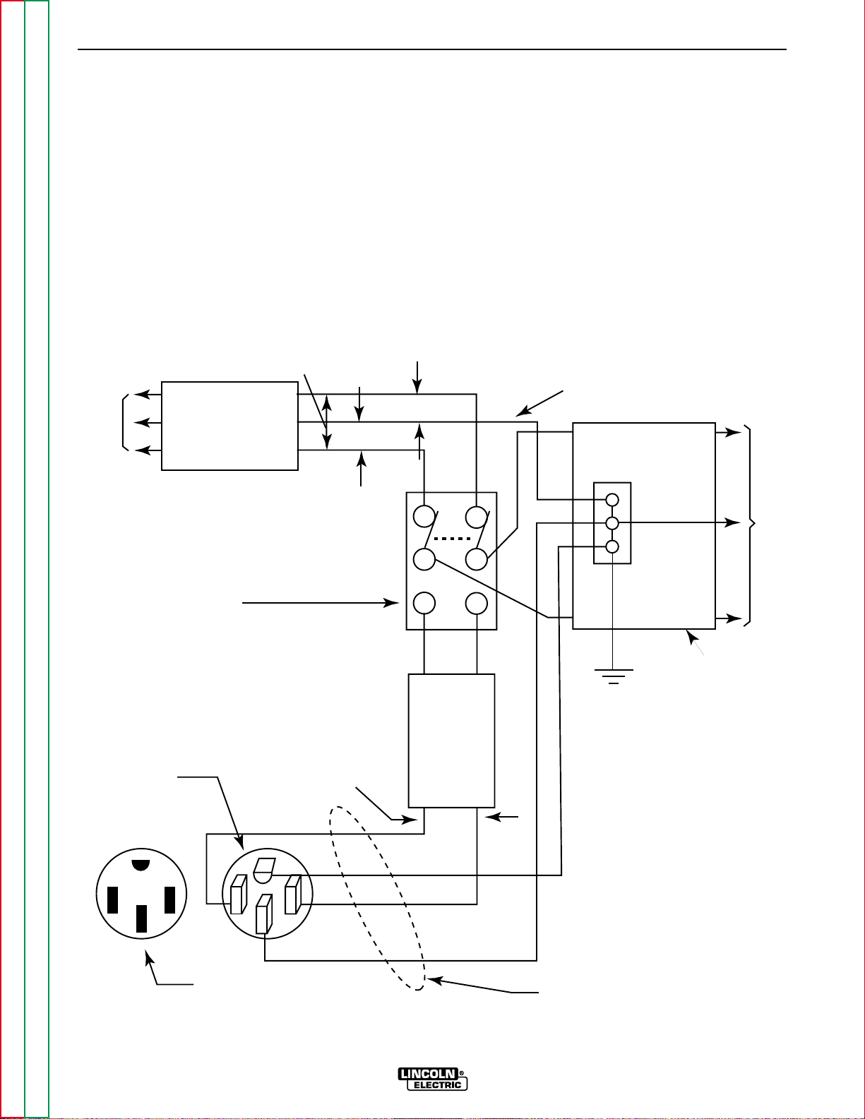
1. Install the double-pole, double-throw switch
between the power company meter and the
premises disconnect.
Switch rating must be the same or greater than the cus-
tomer’s premises disconnect and service over current
protection.
2. Take necessary steps to assure load is limited to
the capacity of the Commander by installing a 50
amp, 240 VAC double-pole circuit breaker.
Maximum rated load for each leg of the 240 VAC
auxiliary is 50 amperes. Loading above the rated
output will reduce output voltage below the allow-
able -10% of rated voltage, which may damage
appliances or other motor-driven equipment and
may result in overheating of the Commander 500
engine.
3. Install a 50 amp 120/240 VAC plug (NEMA Type
14-50) to the double-pole circuit breaker using No.
6, four-conductor cable of the desired length. (The
50 amp, 120/240 VAC plug is available in the
optional K802R plug kit.)
4. Plug this cable into the 50 amp 120/240 volt receptacle on the Commander 500 case front.
A-8 A-8
INSTALLATION
COMMANDER 500
Return to Section TOC Return to Section TOC Return to Section TOC Return to Section TOC
Return to Master TOC Return to Master TOC Return to Master TOC Return to Master TOC
FIGURE A.2 – CONNECTION OF THE COMMANDER 500 TO PREMISES WIRING
240 Volt
60 Hz.
3-Wire
Service
POWER
COMPANY
METER
240 VOLT
120 VOLT
120 VOLT
LOAD
N
NEUTRAL
BUS
GROUND
PREMISES
DISCONNECT AND
SERVICE
OVERCURRENT
PROTECTION
GND
N
NOTE: No. 6 COPPER CONDUCTOR CABLE. SEE
NATIONAL ELECTRICAL CODE FOR ALTERNATE WIRE
SIZE RECOMMENDATIONS.
240 VOLT
GROUNDED CONDUCTOR
50AMP
240 VOLT
DOUBLE
POLE
CIRCUIT
BREAKER
DOUBLE POLE DOUBLE THROW
SWITCH RATING TO BE THE SAME
AS OR GREATER THAN PREMISES
SERVICE OVERCURRENT
PROTECTION.
50 AMP, 120/240
VOLT PLUG
NEMA TYPE 14-50
50 AMP, 120/240 VOLT
RECEPTACLE
Page 15

Operation...............................................................................................................................Section B
Operating Instructions.................................................................................................................B-2
Safety Instructions.......................................................................................................................B-2
General Description ....................................................................................................................B-2
Recommended Applications.................................................................................................B-3
Design Features and Advantages........................................................................................B-3
Welding Capability................................................................................................................B-4
Controls and Settings ..................................................................................................................B-4
Engine Controls....................................................................................................................B-5
Welder Controls....................................................................................................................B-6
Auxiliary Power Controls ......................................................................................................B -7
Engine Operation........................................................................................................................B-8
Starting the Engine...............................................................................................................B-8
Stopping the Engine.............................................................................................................B-8
Break-In Period................................................................................................................ .....B-8
Typical Fuel Consumption....................................................................................................B-8
Welder Operation........................................................................................................................B-9
Stick Welding........................................................................................................................B-9
Pipe Welding.........................................................................................................................B-9
Constant Current (CC) Welding............................................................................................B-9
TIG Welding..........................................................................................................................B-9
Wire Feed (Constant Voltage) Welding ..............................................................................B-11
Auxiliary Power Operation .........................................................................................................B-11
Simultaneous Welding and Auxiliary Power Loads ............................................................B-11
Arc Gouging........................................................................................................................B-11
Paralleling ...........................................................................................................................B-11
Extension Cord Recommendations...........................................................................................B-12
Section B-1 Section B-1
TABLE OF CONTENTS
- OPERATION SECTION -
COMMANDER 500
Return to Master TOC Return to Master TOC Return to Master TOC Return to Master TOC
Page 16

B-2 B-2
OPERATION
COMMANDER 500
Return to Section TOC Return to Section TOC Return to Section TOC Return to Section TOC
Return to Master TOC Return to Master TOC Return to Master TOC Return to Master TOC
OPERATING INSTRUCTIONS
Read and understand this entire section before operating your Commander 500.
SAFETY INSTRUCTIONS
Do not attempt to use this equipment until you have
thoroughly read all operating and maintenance manuals supplied with your machine. They include important safety precautions: detailed engine starting, operating, and maintenance instructions and parts lists.
ELECTRIC SHOCK can kill.
• Do not touch electrically live parts or
electrodes with your skin or wet clothing.
• Insulate yourself from the work and
ground.
• Always wear dry insulating gloves.
FUMES AND GASES CAN BE
DANGEROUS.
• Keep your head out of fumes.
• Use ventilation or exhaust to remove
fumes from breathing zone.
WELDING SPARKS CAN
CAUSE FIRE OR EXPLOSION.
• Keep flammable material away.
• Do not weld on containers that have
held combustibles.
ARC RAYS CAN BURN.
• Wear eye, ear, and body protection.
ENGINE EXHAUST can kill.
• Use in open, well ventilated areas or
vent exhaust outside
• Do not stack anything near the engine.
MOVING PARTS can injure.
• Do not operate with doors open or
guards off.
• Stop engine before servicing.
• Keep away from moving parts
Only qualified personnel should operate this
equipment.
ADDITIONAL SAFETY PRECAUTIONS
Always operate the welder with the hinged door closed
and the side panels in place, as these provide maximum protection from moving parts and insure proper
cooling air flow.
GENERAL DESCRIPTION
The Commander 500 is a diesel engine-driven welding
power source. The machine uses a brush type alternating current generator for DC multi-purpose welding
and for 120/240 VAC auxiliary standby power. The
welding control system uses state of the art Chopper
Technology.
The generator has a single sealed bearing for maintenance free service. The rotor is a copper wound design
with two slip rings and brushes. The stator is wound
entirely with heavy gauge copper wire and insulated
with NEMA class F insulation material. The stator is
then impregnated with three layers of high quality varnish. After the stator is assembled using tie bars, the
entire assembly is covered with an environmentally
protective coating. These measures insure trouble-free
operation in the harshest environments.
The fuel tank is made from high density polyethylene
and holds 25 gallons (94.6 liters) of diesel fuel. This
will provide enough fuel to run for more than 12 hours
at full load.
The Deutz F3L-912 engine is equipped with a standard, heavy duty, combination fuel filter/water separator element.
WARNING
Page 17

RECOMMENDED APPLICATIONS
WELDER
The Commander 500 provides excellent constant current DC welding output for stick (SMAW) and TIG welding. The Commander 500 also provides excellent constant voltage DC welding output for MIG (GMAW) and
Innershield (FCAW) welding.
GENERATOR
The Commander 500 provides smooth 120/240 VAC
output for auxiliary power and emergency standby
power.
DESIGN FEATURES AND ADVANTAGES
K1639-2 COMMANDER 500 DELUXE MODEL
FEATURES
FOR WELDING
• Excellent DC multi-purpose welding for stick, MIG,
TIG, cored wire and arc gouging applications.
• 30 to 500 amps output in five slope-controlled ranges
for out-of position and pipe electrodes, one constant
current output range for general purpose welding,
one constant voltage range for MIG wire and cored
wire welding and one 20-250 amp range for “Touch
Start” TIG welding.
• 100% duty cycle at 500 amps output and 50% duty
cycle at 575 amps output.
• Dual 3-digit output meters are provided (optional on
K1639-1) for presetting the weld amperage or voltage and displaying the actual amperage and voltage
during welding. The meters use superbrite L.E.D.'s
for improved readability in full sunlight.
LOOK-BACK FEA TURE:After welding has stopped,
both displays will remain on for 7 seconds with the
last current and voltage value displayed. During this
time, the left-most decimal point in each display will
be FLASHING.
• Standard remote control capability with 14-pin and
6-pin connectors for easy connection of Lincoln
remote control accessories.
• An internal "Solid State" contactor allows for the
selection of "hot" or "cold" output terminals with a
toggle switch on the control panel.
• “Arc Control”potentiometer in Wire and Stick modes
for precise adjustment of arc characteristics.
• Advanced circuitry to prevent pop-outs in the five
slope modes.
FOR AUXILIARY POWER
• 12,000 watts of 120/240 VAC, 60Hz auxiliary power.
• Power for tools, 120/240 VAC lights, electric pumps
and for standby emergency power.
• Drive a 5 HP motor (provided it is started under no
load).
• T wo 20 amp 120 VAC duplex receptacles for up to 40
amps of 120 VAC power.
• One 50 amp, 120/240 VAC dual voltage receptacle
for up to 50 amps of 240 V AC, and up to 50 amps per
side to separate branch circuits (not in parallel) of
120 VAC single-phase auxiliary power. Allows easy
connection to premises wiring.
• Weld and AC auxiliary power at the same time (within machine total capacity).
OTHER FEATURES
• Deutz 3-cylinder, air/oil cooled diesel engine.
Designed for long life, easy maintenance, and excellent fuel economy.
• Engine protection system shuts the engine down for
low oil pressure, high oil temperature, or a broken
fan/engine alternator belt.
• Gauges for oil pressure, oil temperature, engine
alternator output, and fuel level.
• Indicator lights for low oil pressure, high oil temperature, engine alternator low output/broken belt, and
low fuel level (on K1639-2 only).
• Automatic low fuel shutdown before running out of
fuel (K1639-2 only).
• Engine hour meter standard on all models.
• Extended range 25 gallon (94.6 l) fuel tank.
• Automatic idler reduces engine speed when not
welding or drawing auxiliary power. This feature
reduces fuel consumption and extends engine life.
• Compact size fits crosswise in full size pickup truck.
• Single-side engine service.
• Copper alternator windings and high temperature
insulation for dependability and long life.
• New paint system on case and base for outstanding
corrosion protection.
B-3 B-3
OPERATION
COMMANDER 500
Return to Section TOC Return to Section TOC Return to Section TOC Return to Section TOC
Return to Master TOC Return to Master TOC Return to Master TOC Return to Master TOC
Page 18
K1639-1 COMMANDER 500 STANDARD MODEL
• The K1639-1 is the standard version of the
Commander 500 and has all the features of the
K1639-2 Deluxe version except that there are no
gauges, low fuel light, nor dual output meters. This
version does have fully functional engine protection
for low oil pressure, high oil temperature, and alternator output with associated lights.
• A field-installed Dual Output Meter and Gauge Kit
(K-1768-1) is available for the K1639-1 Commander
500.The kit includes dual output meters, oil pressure
gauge, oil temperature gage, and alternator ammeter.
WELDING CAPABILITY
The Commander 500 is rated at 500 amps, 40 VDC at
100% duty cycle and 575 amps, 36 VDC at 50% duty
cycle. The maximum open circuit voltage at 1900 RPM
is 80 volts. The weld current is variable from 30 to 575
amps.
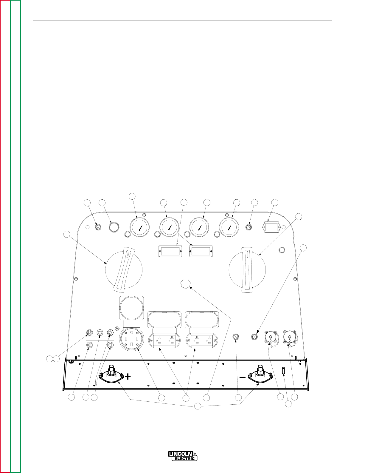
CONTROLS AND SETTINGS
All welder and engine controls are located on the case
front panel. Refer to Figure B.1 and the explanations
that follow.
B-4 B-4
OPERATION
COMMANDER 500
Return to Section TOC Return to Section TOC Return to Section TOC Return to Section TOC
Return to Master TOC Return to Master TOC Return to Master TOC Return to Master TOC
FIGURE B.1 – CASE FRONT PANEL CONTROLS
3
2
1
4
10
5
6
7 8
OIL
9
1917
FUEL
TEMP
OIL
PRESS
AMPS
9
11
21
19
15
14
16
23
13
20
12
22
18
Page 19

ENGINE CONTROLS (Items 1 through 8)
1. RUN/STOP SWITCH
When placed in the RUN position, this switch energizes
the fuel solenoid and other electric accessories. When
placed in the STOP position, the flow of fuel to the
injection pump is stopped to shut down the engine.
NOTE: If the switch is left in the RUN position and the
engine is not running, the fuel solenoid will be engaged
for 15 seconds and then shut down. This is to protect
the battery from discharge. After 15 seconds, the
RUN/STOP switch must be toggled off then on before
starting.
2. START PUSHBUTTON
Energizes the starter motor to crank the engine. With
the engine RUN/STOP switch in the RUN position,
push and hold the Start button to crank the engine;
release as the engine starts. The Start button must be
depressed for a minimum of two seconds. Do not
press it while the engine is running, since this can
cause damage to the ring gear and/or starter motor.
3. FUEL LEVEL GAUGE AND LIGHT
(K1639-2 only) - Displays the level of diesel fuel in the
25-gallon (94.6 liter) fuel tank. The yellow light turns on
when the fuel gage reaches the reserve level. Once the
reserve level is reached, the engine protection system
will shut down the engine after 30 minutes of operation.
The machine can be restarted and operated for an
additional 30 minutes before the protection system will
shut down the engine. This ability to override the
engine protection allows the operator to “finish up” if
necessary. The operator must watch the fuel level
closely to prevent running out of fuel and having to
bleed the system.
4. ENGINE TEMPERATURE GAUGE (K1639-2
Std., K1639-1 Opt.) AND LIGHT
The gauge displays the engine oil temperature. The
yellow temperature light remains off under normal
operating temperatures. If the light turns on, the engine
protection system will shut down the engine. Check for
restrictions at the engine cooling air inlets and outlets.
(Consult the engine Operator’s Manual.) Check for
loose or disconnected leads at the temperature sender
located on the engine. Check the engine cooling blower belt. Also, check to be sure that the welder loads are
within the rating of the welder. The light will remain on
when the engine has been shut down due to an overtemperature condition.
5. OIL PRESSURE GAUGE (K1639-2 Std.,
K1639-1 Opt.) AND LIGHT
The gauge displays the engine oil pressure when the
engine is running. The yellow oil pressure light remains
off with proper oil pressure. If the light turns on, the
engine protection system will stop the engine. Check
for proper oil level and add oil if necessary. Check for
loose or disconnected leads at the oil pressure sender
located on the engine. The light will go on and stay on
when the RUN/STOP switch is switched to the RUN
position with the engine not running.
6. ENGINE ALTERNATOR AMMETER
(K1639-2 Std., K1639-1 Opt.) AND LIGHT
The yellow engine alternator light is off when the battery charging system is functioning normally. If the light
turns on, the engine protection system will shut down
the engine. Check the engine cooling blower belt. Also,
the alternator or the voltage regulator may not be operating correctly. The light may also come on due to a
faulty flashing circuit. The light will remain on when the
engine has been shut down due to a fault in the alternator, regulator, or the cooling blower belt.
7. IDLER SWITCH
Has two positions as follows:
A) In the HIGH position , the engine runs at the
high idle speed controlled by the governor.
B) In the AUTO / position, the idler oper-
ates as follows:
a. When switched from HIGH to AUTO or after
starting the engine, the engine will operate at
full speed for approximately 12 seconds and
then go to low idle speed.
b. When the electrode touches the work or power
is drawn for lights or tools (approximately 100
Watts minimum) the engine accelerates and
operates at full speed.
c. When welding ceases or the AC power load is
turned off, a fixed time delay of approximately
12 seconds starts.
d. If the welding or AC power load is not restarted
before the end of the time delay, the idler
reduces the engine speed to low idle speed.
e. The engine will automatically return to high idle
speed when the welding load or AC power load
is reapplied.
B-5 B-5
OPERATION
COMMANDER 500
Return to Section TOC Return to Section TOC Return to Section TOC Return to Section TOC
Return to Master TOC Return to Master TOC Return to Master TOC Return to Master TOC
Page 20

Idler Operational Exceptions
When the WELDING TERMINALS switch is in the
“Welding Terminals Remotely Controlled” position, the
idler will operate as follows:
a. When the triggering device (Amptrol, Arc Start
Switch, etc.) is pressed, the engine will accelerate
and operate at full speed provided a welding load
is applied within approximately 15 seconds.
• If the triggering device remains pressed but no
welding load is applied within approximately 15
seconds, the engine will return to low idle speed.
• If the triggering device is released or welding
ceases, the engine will return to low idle speed
after approximately 15 seconds.
8. HOUR METER
The hour meter displays the total time that the engine
has been running. This meter is a useful indicator for
scheduling preventive maintenance.
WELDER CONTROLS (Items 9 through 13 )
9. WELD MODE & OUTPUT CONTROL
These two controls allow you to select between various
welding output slopes and adjust the desired welding
output. Refer to Table B.1 for a description of how
these two controls work.
10. DIGITAL OUTPUT METERS
The digital output meters are located in the center of
the control panel between the two large control knobs.
The meters allow the output current level to be set prior
to welding in stick mode, and voltage level to be set
prior to welding in the wire modes. During the welding
process the meters display the actual output current
and voltage, within ±5% accuracy.
The digital meters allow the output voltage (CV-WIRE
mode) or current (CC-STICK, PIPE and TIG modes) to
be set prior to welding using the OUTPUT control dial.
During welding, the meters display the actual output
voltage (VOLTS) and current (AMPS). A memory feature holds the display of both meters on for seven seconds after the welding is stopped. This allows the operator to read the actual current and voltage just prior to
when welding was ceased. While the display is being
held the left-most decimal point in each display will be
flashing. The accuracy of the meters is +/- 3%.
11. WELDING TERMINALS SWITCH
The toggle switch on the control panel labeled WELD
TERMINALS ON and REMOTELY CONTROLLED is
used to control the operation of the “solid state contactor.” The switch allows for the selection of “Hot” or
“Cold” welding terminals.
With the switch in the WELD TERMINALS ON position,
the contactor is closed and the welding terminals are
always “Hot.”
With the switch in the REMOTELY CONTROLLED
position, the contactor operation is controlled by an
Amptrol, Arc Start Switch or some other type of triggering device through the use of a control cable connected to the 14-pin amphenol.
When the triggering device is pressed, the contactor is
closed and the welding terminals are “Hot.”
When the triggering device is released, the contactor is
opened and the welding terminals are “Cold.”
NOTE: The new Chopper Technology control circuitry
automatically senses when a remote output control pot
is plugged into either amphenol. Therefore, there is no
need for a local / remote switch.
TABLE B.1 – WELD MODE AND OUTPUT
CONTROL FUNCTIONS
Application Weld Mode
1
Output
2
Sloped Output 5 Range
for Pipe Settings
Welding 90, 150, 200,
350, 500 (max. Provides a Fine
current on each Adjustment of
setting) Welding Current
from
Touch Start TIG 1 Range Setting Min (1) to Max
Welding 15-200 Amps (10) within each
range
Constant Current 1 Range Setting
Output for 20-250 Amps
Fabrication and
General Purpose
Welding
Constant Voltage 1 Range Setting Provides Fine
Output for MIG 14 to 40 Volts Voltage
WIRE or Adjustment
CORED WIRE
Welding
1
If the WELD MODE switch is positioned between settings, the previous setting is maintained until the switch is properly positioned on
a setting.
2
OUTPUT also controls O.C.V. while in the 5 sloped output ranges.
B-6 B-6
OPERATION
COMMANDER 500
Return to Section TOC Return to Section TOC Return to Section TOC Return to Section TOC
Return to Master TOC Return to Master TOC Return to Master TOC Return to Master TOC
M
M
Page 21

12. 6 - PIN CONNECTOR (AMPHENOL)
The 6-pin amphenol located on the control panel
allows for connection of interfacing equipment.
13. WELD OUTPUT TERMINALS + AND -
These 1/2 - 13 studs with flange nuts provide welding
connection points for the electrode and work cables.
For positive polarity welding, the electrode cable connects to the “+” terminal and the work cable connects
to this “-” terminal. For negative polarity welding, the
work cable connects to the “+” terminal and the electrode cable connects to this “-” terminal.
AUXILIARY POWER CONTROLS
(Items 14 through 18 )
14. 120/240VAC RECEPTACLE
This is a 120/240VAC (14-50R) receptacle that
provides 240VAC. Or, it can be split for 120VAC single-phase auxiliary power. This receptacle has a 50
amp rating. Refer to AUXILIARY POWER RECEP-
TACLES section in the Installation section for further
information about this receptacle. Also refer to the
AUXILIARY POWER OPERA TION later in this section.
15. 50 AMP CIRCUIT BREAKERS
These circuit breakers provide separate overload
current protection for each 120V circuit at the 240V
receptacle.
16. 120VAC RECEPTACLES
These two 120VAC (5-20R) receptacles provide
120VAC for auxiliary power. Each receptacle has a 20
amp total rating. Refer to AUXILIARY POWER
RECEPTACLES in the Installation section for further
information about these receptacles. Also refer to the
AUXILIARY POWER OPERA TION later in this section.
17. 20 AMP CIRCUIT BREAKERS
These circuit breakers provide separate overload current protection for each 120V receptacle.
18. GROUND STUD
Provides a connection point for connecting the
machine case to earth ground for the safest grounding
procedure. Refer to MACHINE GROUNDING in the
Installation section for proper machine grounding information.
19. 20 AMP CIRCUIT BREAKER
This circuit breaker provides overload protection for the
120 VAC circuit in the 14-pin amphenol.
20. VOLTMETER +/- SWITCH
Changes the polarity display on the wire feeder.
21. 10 AMP CIRCUIT BREAKER
This circuit breaker provides overload protection for the
42 VAC circuit in the 14-pin amphenol.
22. 14 - PIN CONNECTOR (AMPHENOL)
For quick connection of interfacing equipment.
23. ARC CONTROL
The ARC CONTROL potentiometer is active in two
modes: CC - STICK and CV - WIRE with different purposes in each mode.
CC - STICK mode: In this mode, the ARC CONTROL
knob sets the short circuit current during stick welding.
Increasing the number from 1 to 10 increases the short
circuit current. This prevents sticking of the electrode to
the plate at low welding current settings. This also
increases spatter. It is recommended that the control
be set to the minimum number without electrode sticking.
CV - WIRE mode: In this mode increasing the number
from 1 to 10 changes the arc from soft and washed in
to crisp and narrow. It acts as an inductance control.
The proper setting depends on the application and
operator preference.
In general, MIG welding performs best in the “SOFT”
range and Innershield in the “CRISP” range.
B-7 B-7
OPERATION
COMMANDER 500
Return to Section TOC Return to Section TOC Return to Section TOC Return to Section TOC
Return to Master TOC Return to Master TOC Return to Master TOC Return to Master TOC
Page 22

ENGINE OPERATION
STARTING THE ENGINE
1. Open the engine compartment door and check that
the fuel shutoff valve located to the left of the fuel filter housing is in the open position (lever to be in line
with the hose).
2. Check for proper oil level on the oil dipstick. Close
engine compartment door.
3. Remove all plugs connected to the AC power receptacles.
4. Set IDLER switch to “AUTO”.
5. Set the RUN/STOP switch to RUN. Observe that
all engine protection lights momentarily turn on.
Some lights may turn off before starting. Check the
fuel gauge (K1639-2 only) to make sure that there
is an adequate fuel level.
6. Press and hold the engine START button for a minimum of two seconds.
7. Release the engine STARTbutton when the engine
starts.
8. Check that the indicator lights are off. If the LOW
FUEL light is on (K1639-2 only), the engine will shut
down 30 minutes after starting. If any other indicator light is on after starting, the engine will shut
down in a few seconds. Investigate any indicated
problem.
9. Allow the engine to warm up at low idle speed for
several minutes before applying a load and/or
switching to high idle. Allow a longer warm-up time
in cold weather.
COLD WEATHER STARTING
With a fully charged battery and the proper weight oil,
the engine should start satisfactorily even down to
about 0°F. If the engine must be frequently started
below 10°F, it may be desirable to install the optional
ether starter kit (K825-1). Installation and operating
instructions are included in the kit.
STOPPING THE ENGINE
1. Switch the RUN/STOP switch to STOP. This turns
off the voltage supplied to the shutdown solenoid. A
backup shutdown can be accomplished by shutting
off the fuel valve located on the fuel line.
BREAK-IN PERIOD
The engine used to supply power for your welder is a
heavy duty, industrial engine. It is designed and built
for rugged use. It is very normal for any engine to use
small quantities of oil until the break-in is accomplished. Check the oil level twice a day during the
break-in period (about 200 running hours).
During break-in, subject the Commander 500 to heavy
loads. Avoid long periods running at idle. Before stopping the engine, remove all loads and allow the engine
to cool several minutes.
The heavy loading of the engine during break-in, within the rating of the machine, is recommended to properly seat the piston rings and prevent wetstacking.
Wetstacking is an accumulation of unburned fuel
and/or lubricant in the form of a set, black, tar-like substance in the exhaust pipe. The rings are seated and
the break-in period is complete when there are no
longer any signs of wetstacking, which should occur
within the first 50 to 100 hours of operation.
Using your welder at low amperages with long idle running periods during the break-in period may result in a
glaze forming on the engine cylinder walls and the
rings not seating properly. No amount of loading will
properly seat the pistons rings after they are glazed
over.
TYPICAL FUEL CONSUMPTION
Refer to Table B.2 for typical fuel consumption of the
Commander 500 engine for various operating
scenarios.
B-8 B-8
OPERATION
COMMANDER 500
Return to Section TOC Return to Section TOC Return to Section TOC Return to Section TOC
Return to Master TOC Return to Master TOC Return to Master TOC Return to Master TOC
CAUTION
CAUTION
Page 23

Table B.2 – DEUTZ F3L 912
ENGINE FUEL CONSUMPTION
Deutz F3L 912 Running Time
44.2 Hp for 25 gallons
@ 1800 RPM (Hours)
Low Idle - No .47 gallons/hour 53.2
Load 1475 RPM (1.77 liters/hour)
High Idle - No .66 gallons/hour 37.9
Load 1900 RPM (2.50 liters/hour)
DC CC Weld 1.94 gallons/hour 12.9
Output 500 (7.34 liters/hour)
Amps @ 40 Volts
Auxiliary Power 1.31 gallons/hour 19.1
12,000 VA (4.96 liters/hour)
WELDER OPERATION
STICK WELDING
The Commander 500 can be used with a broad range
of DC stick electrodes.
The “WELD MODE” switch provides five overlapping
slope controlled current ranges. The OUTPUT adjusts
the current from minimum to maximum within each
range. Voltage is also controlled by the OUTPUTin the
slope controlled setting. These slope controlled settings are intended for “out-of-position” welding, including pipe welding, where the operator would like to control the current level by changing the arc length.
PIPE WELDING
The Commander 500 is equipped with special circuitry
to minimize pop-outs in the five slope modes at any
open circuit voltage.
For a soft arc characteristic, set the WELD MODE
switch to the lowest setting that still provides the current you need and set the OUTPUT near maximum.
For example: to obtain 140 amps and a soft arc, set
the WELD MODE switch to the 150 MAX position and
then adjust the OUTPUT for 140 amps.
When a forceful, "digging" arc is required, use a higher
setting and lower the open circuit voltage. For example:
to obtain 140 amps and a forceful arc, set the WELD
MODE to the 250 MAX position and then adjust the
OUTPUT to get 140 amps.
CONSTANT CURRENT (CC) WELDING
In the CC - STICK position of 30 to 575, the WELD
MODE switch is designed for horizontal welds with all
types of electrodes, especially low hydrogen. The
OUTPUT adjusts the full range of 30 to 575 amps. This
setting provides a soft, constant current arc. If a more
forceful arc is desired, select the proper range from the
slope controlled current ranges.
In the CC mode, sticking can be prevented by adjusting the ARC CONTROL. Turning this control clockwise
increases the short circuit current, thus preventing
sticking. This is another way of increasing arc force.
TIG WELDING
The furthest position clockwise of the WELD MODE
switch is for TIG welding in the range of 20 amps to 250
amps, with a “Touch Start” feature. To initiate a weld,
the OUTPUT is first set to the desired current, and the
tungsten is touched to the work. During the time the
tungsten is touching the work, there is very little voltage
or current and, in general, no tungsten contamination.
Then, the tungsten is gently lifted off the work in a rocking motion, which establishes the arc.
The Commander 500 can be used in a wide variety of
DC Tungsten Inert Gas (TIG) welding applications. In
general the “Touch Start” feature allows contaminationfree starting without the use of a Hi-Freq unit. But the
K930-1 or -2 TIG module or K799 Hi-Freq unit can be
used with the Commander 500. The settings for these
follow the tungsten current range table, Table B.3.
B-9 B-9
OPERATION
COMMANDER 500
Return to Section TOC Return to Section TOC Return to Section TOC Return to Section TOC
Return to Master TOC Return to Master TOC Return to Master TOC Return to Master TOC
Page 24

COMMANDER 500 SETTINGS WHEN USING THE
K799 HI-FREQ UNIT
• Set the WELD MODE switch to the 20-250 setting
(TIG).
• Set the IDLER switch to the HIGH position.
• Set the WELDING TERMINALS switch to the WELD
TERMINALS ON position. This will close the solid
state contactor and provide an always “hot” electrode.
NOTE: This is necessary because the K799 circuitry
with respect to the #2 and #4 leads does not provide
the proper signal to open and close the solid state contactor in the Commander 500.
COMMANDER 500 SETTINGS WHEN USING THE
K930-1 TIG MODULE
• Set the WELD MODE switch to the 20-250 setting
(TIG).
• Set the IDLER switch to the AUTO position.
• Set the WELDING TERMINALS switch to the
REMOTELY CONTROLLED position. This will keep
the solid state contactor open and provide a “cold”
electrode until the triggering device (Amptrol or Arc
Start Switch) is pressed.
B-10 B-10
OPERATION
COMMANDER 500
Return to Section TOC Return to Section TOC Return to Section TOC Return to Section TOC
Return to Master TOC Return to Master TOC Return to Master TOC Return to Master TOC
TABLE B.3 – TYPICAL CURRENT RANGES1FOR TUNGSTEN ELECTRODES
2
Approximate Argon Gas Flow Rate
DCEN (-) DCEP (+) C.F.H. (l/min.)
Tungsten
Electrode 1%, 2% 1%, 2% TIG TORCH
Diameter Thoriated Thoriated Nozzle
in. (mm) Tungsten Tunsten Aluminum Stainless Steel Size
4, 5
0.010 (.25) 2-15
3
3-8 (2-4) 3-8 (2-4) #4, #5, #6
0.020 (.50) 5-20
3
5-10 (3-5) 5-10 (3-5)
0.40 (1.0) 15-80
3
5-10 (3-5) 5-10 (3-5)
1/16 (1.6) 70-150 10-20 5-10 (3-5) 9-13 (4-6) #5, #6
3/32 (2.4) 150-250 15-30 13-17 (6-8) 11-15 (5-7) #6, #7, #8
1/8 (3.2) 250-400 25-40 15-23 (7-11) 11-15 (5-7)
5/32 (4.0) 400-500 40-55 21-25 (10-12) 13-17 (6-8) #8, #10
3/16 (4.8) 500-750 55-80 23-27 (11-13) 18-22 (8-10)
1/4 (6.4) 750-1000 80-125 28-32 (13-15) 23-27 (11-13)
1
When used with argon gas. The current ranges shown must be reduced when using argon/helium or pure helium shielding gases.
2
Tungsten electrodes are classified as follows by the American Welding Society (AWS):
Pure EWP
1% Thoriated EWTh-1
2% Thoriated EWTh-2
2
Though not yet recognized by the AWS, Ceriated Tungsten is now widely accepted as a substitute for 2% Thoriated Tungsten in AC and DC
applications.
3
DCEP is not commonly used in these sizes.
4
TIG torch nozzle “sizes” are in multiples of 1/16ths of an inch:
# 4 = 1/4 in. (6 mm) # 7 = 7/16 in. (11 mm)
# 5 = 5/16 in. (8 mm) # 8 = 1/2 in. (12.5 mm)
# 6 = 3/8 in. (10 mm) #10 = 5/8 in. (16 mm)
5
TIG torch nozzles are typically made from alumina ceramic. Special applications may require lava nozzles, which are less prone to breakage, but cannot withstand high temperatures and high duty cycles.
Page 25

WIRE FEED (CONSTANT VOLTAGE)
WELDING
Connect a wire feeder to the Commander 500 and set
welder controls according to the instructions listed earlier in this section.
The Commander 500 in the CV-WIRE position can be
used with a broad range of flux cored wire (Innershield
and Outershield) electrodes and solid wires for MIG
welding (gas metal arc welding). Welding can be finely
tuned using the ARC CONTROL.
Some recommended Innershield electrodes are: NR311, NS-3M, NR-207, NR-203 Ni 1%, NR-204-H.
Recommended Outershield electrodes are: 0S-70, 0S71M.
Some recommended solid wires for MIG welding are:
.035 (0.9 mm), .045 (1.1 mm) and .052 (1.3 mm), L-50
and L-56, .035 (0.9 mm) and .045 (1.1 mm) Blue Max
MIG 308 LS.
For any electrodes, including the above recommendations, the procedures should be kept within the rating of
the machine. For additional electrode information, see
Lincoln publications N-675, GS-100 and GS-210.
AUXILIARY POWER OPERATION
Start the engine and set the IDLER control switch to
the desired operating mode. Full power is available
regardless of the welding control settings, if no welding
current is being drawn.
The auxiliary power of the Commander consists of two
20 Amp-120VAC (5-20R) duplex receptacles and one
50 Amp-120/240 VAC (14-50R) receptacle. The
120/240VAC receptacle can be split for single phase
120 VAC operation.
The auxiliary power capacity is 12,000 watts of 60 Hz,
single phase power. The auxiliary power capacity rating
in watts is equivalent to volt-amperes at unity power
factor. The maximum permissible current of the 240
V AC output is 50 A. The 240 VAC output can be split to
provide two separate 120 VAC outputs with a maximum permissible current of 50 Aper output to two separate 120 VAC branch circuits. Output voltage is within
± 10% at all loads up to rated capacity.
NOTE: The 120/240V receptacle has two 120V outputs of different phases and cannot be paralleled.
The auxiliary power receptacles should only be used
with three-wire grounded type plugs or approved double insulated tools with two wire plugs.
The current rating of any plug used with the system
must be at least equal to the current capacity of the
associated receptacle.
SIMULTANEOUS WELDING AND
AUXILIARY POWER LOADS
It must be noted that the above auxiliary power ratings
are with no welding load. Simultaneous welding and
power loads are specified in Table B.4. The permissible currents shown assume that current is being drawn
from either the 120 VAC or 240 VAC supply (not both
at the same time).
ARC GOUGING
For optimal performance when arc gouging, set the
Commander 500 WELD MODE switch to the CC STICK position, and the ARC CONTROL to 10.
Set the OUTPUT knob to adjust output current to the
desired level for the gouging electrode being used
according to the ratings in the following table:
Electrode Current Range
Diameter (DC, electrode positive)
1/8” 30-60 Amps
5/32” 90-150 Amps
3/16” 150-200 Amps
1/4” 200-400 Amps
5/16” 250-400 Amps
3/8” 350-575 Amps*
* Maximum current setting is limited to the Commander
500 maximum of 575 Amps.
PARALLELING
When paralleling machines in order to combine their
outputs, all units must be operated in the CC - STICK
mode only. To achieve this, turn the WELD MODE
switch to the CC - STICK position. Operation in other
modes may produce erratic outputs and large output
imbalances between the units.
B-11 B-11
OPERATION
COMMANDER 500
Return to Section TOC Return to Section TOC Return to Section TOC Return to Section TOC
Return to Master TOC Return to Master TOC Return to Master TOC Return to Master TOC
Page 26

B-12 B-12
OPERATION
COMMANDER 500
Return to Section TOC Return to Section TOC Return to Section TOC Return to Section TOC
Return to Master TOC Return to Master TOC Return to Master TOC Return to Master TOC
TABLE B.4 – COMMANDER 500 SIMULTANEOUS WELDING AND POWER LOADS
Permissible Permissible Auxiliary
Welding Power - Watts Current in Amperes
Output Range (Unity Power
Setting Welding Output Factor) @ 120 V ± 10%* @ 240 V ± 10%*
30-575 500A/40V 0 0 0
500 500A/40V 0 0 0
350 350A/30V 9500 80* 40
250 250A/29V 12000 100** 50
150 150A/27V 12000 100** 50
90 90A/25V 12000 100** 50
* Each duplex receptacle is limited to 20 amps.
** Not to exceed 50 Aper 120 VAC branch circuit when splitting the 240 VAC output.
TABLE B.5 – COMMANDER 500 EXTENSION CORD LENGTH RECOMMENDATIONS
Current
(Amps)
15
15
20
20
25
30
38
50
Voltage
(Volts)
120
240
120
240
240
240
240
240
Load
(Watts)
1800
3600
2400
48010
6000
7200
9000
12000
30
60
(9)
(18)
40
75
30
60
(12)
(23)
(9)
(18)
75
150
50
100
90
75
(23)
(46)
(15)
(30)
(27)
(23)
125
225
88
175
150
120
100
(38)
(69)
(27)
(53)
(46)
(37)
(30)
175
350
138
275
225
175
150
125
(53)
(107)
(42)
(84)
(69)
(53)
(46)
(38)
300
600
225
450
250
300
250
200
(91)
(183)
(69)
(137)
(76)
(91)
(76)
(61)
Maximum Allowable Cord Length in ft. (m) for Conductor Size
Conductor size is based on maximum 2.0% voltage drop.
14 AWG 12 AWG 10 AWG 8 AWG 6 AWG 4 AWG
EXTENSION CORD
RECOMMENDATIONS
An extension cord can be used with the auxiliary power
outputs as long as it is of ample size. Table B.5 lists
permissible extension cord lengths based on conductor size and auxiliary power output.
Page 27

Accessories ..........................................................................................................................Section C
Options/Accessories ...................................................................................................................C-2
Field Installed Options ........................................................................................................ ..C-2
Stick Welding Accessories....................................................................................................C-2
TIG Welding Accessories .....................................................................................................C-2
Semiautomatic Welding Accessories....................................................................................C-3
Connection of Lincoln Electric Wire Feeders.......................................................................C-3
Connection of the LN-7 Using K867 Universal Adapter................................................C-4
Connection of the LN-7 Using the K584 or K594 Input Cable Assembly......................C-5
Connection of the LN-8 Using the K867 Universal Adapter..........................................C-6
Connection of the LN-8 Using the K595 Input Cable Assembly....................................C-7
Connection of the LN-23-P Using K350-1 Adapter........................................................C-8
Connection of the LN-25 “Across the Arc” .....................................................................C-9
Section C-1 Section C-1
TABLE OF CONTENTS
- ACCESSORIES SECTION -
COMMANDER 500
Return to Master TOC Return to Master TOC Return to Master TOC Return to Master TOC
Page 28

OPTIONS/ACCESSORIES
The following options/accessories are available for
your Commander 500 from your local Lincoln
Distributor.
FIELD INSTALLED OPTIONS
K802N POWER PLUG KIT - Provides a plug for each
receptacle.
K857 25 ft. (8.5 m) or K857-1 100 ft. (30.4 m)
REMOTE CONTROL - Portable control provides same
dial range as the output control on the welder from a
location up to the specified length from the welder. Has
convenient plug for easy connection to the welder. The
Commander 500 is equipped with a 6-pin connector for
connecting the remote control.
K704 ACCESSORY SET - Includes 35 feet (10 m) of
electrode cable and 30 feet (9 m) of work cable, headshield, work clamp and electrode holder. Cable is rated
at 500 amps, 60% duty cycle.
K953-1 TWO-WHEEL TRAILER - For road, in-plant
and yard towing. Road towing with optional fender and
light kit. (For highway use, consult applicable federal,
state and local laws regarding possible additional
requirements.)
• K953-1 Trailer
• K958-1 Ball Hitch
• K958-2 Lunette Eye Hitch
• K959-1 Fender and Light Kit
• K965-1 Cable Storage Rack
K825-1 ETHER START KIT - Provides maximum cold
weather starting assistance for frequent starting below
10° F (-12.2° C). Required Ether tank is not provided
with kit.
K949-1 OIL DRAIN KIT - Includes ball valve, hose and
clamp.
K1690-1 (1 DUPLEX) GFCI KIt - Includes a UL
approved 1 15 volt ground fault circuit interrupter receptacle (duplex type) with cover and installation instructions. Each half of the receptacle is rated 15 amps, but
the maximum total current from the GFCI duplex is limited to 20 amps. The GFCI receptacle replaces the factory installed 115 volt duplex receptacle. Two kits are
required.
K899-1 SPARK ARRESTER KIT - Easily mounts to
standard muffler.
K1816-1 FULL KVA ADAPTER KIT - Plugs into the
120/240V NEMA 14-50R receptacle on the case front
(which accepts 4-prong plugs) and converts it to a
NEMA 6-50R receptacle (which accepts 3-prong
plugs).
K1768-1 DUAL OUTPUT METERS AND GAUGES -
Dual output meters provide preset ability of voltage for
wire welding and current for stick welding. Measures
both current and voltage when welding. Gauges
include battery ammeter, engine temperature, and
engine oil pressure. Fuel gauge is not available in kit
form.
STICK WELDING ACCESSORIES
K704 Accessory Kit, which includes:
• Electrode holder and cable.
• Ground clamp and cable.
• Headshield.
K857 Remote Control Kit is optional for remote current control.
TIG WELDING ACCESSORIES
• Magnum TIG Torch
• Magnum Parts Kit and Argon gas
• K930-ALL TIG Module (not required for
scratch-start DC TIG welding)
• K936-1 Control Cable
• K870 Foot Amptrol
Also available:
• K963-1/-2 Hand Amptrol
• K814 Arc Start Switch
• K937-22 Control Cable Extension
• K937-45 Control Cable Extension
• K844-1 Water Valve
C-2 C-2
ACCESSORIES
COMMANDER 500
Return to Section TOC Return to Section TOC Return to Section TOC Return to Section TOC
Return to Master TOC Return to Master TOC Return to Master TOC Return to Master TOC
Page 29
SEMIAUTOMATIC WELDING
ACCESSORIES
LN-7 OR LN-8 WIRE FEEDERS - Semiautomatic, con-
stant speed wire feeders. For CV operation only.
LN-23P WIRE FEEDER - This portable wire feeder is
capable of CV operation. K350-1 Adapter Kit is
required.
LN-25 WIRE FEEDER - The LN-25 with or without an
external contactor may be used with the Commander
300.
NOTE: Gas-shielded welding requires a Magnum Gun.
Gasless welding requires an Innershield Gun.
OTHER WIRE FEEDERS FOR THE
COMMANDER 300
• NA-3 Automatic Wire Feeder
• LN-742 Semiautomatic Wire Feeder
• Spool gun and K488 Module
HIGH FREQUENCY GENERATORS FOR
TIG APPLICATIONS
The K799 Hi-Freq Unit and the K930-ALL TIG Modules
are suitable for use with the Commander 500. The
Commander 500 is equipped with the required RF
bypass circuitry for the connection of high frequency
generating equipment. The high frequency bypass network supplied with the K799 Hi-Freq Unit does NOT
need to be installed into the Commander 500.
The Commander 500 and any high frequency-generating equipment must be properly grounded. See the
K799 Hi-Freq Unit and the K930-AII TIG Module operating manuals for complete instructions on installation,
operation, and maintenance.
CONNECTION OF LINCOLN
ELECTRIC WIRE FEEDERS
ELECTRIC SHOCK can kill.
• Do not operate with panels open.
• Disconnect NEGATIVE (-) BATTERY
LEAD before servicing.
• Do not touch electrically live parts.
MOVING PARTS can injure.
• Keep guards in place.
• Keep away from moving parts.
• Only qualified personnel should install,
use or service this equipment.
C-3 C-3
ACCESSORIES
COMMANDER 500
Return to Section TOC Return to Section TOC Return to Section TOC Return to Section TOC
Return to Master TOC Return to Master TOC Return to Master TOC Return to Master TOC
WARNING
Page 30
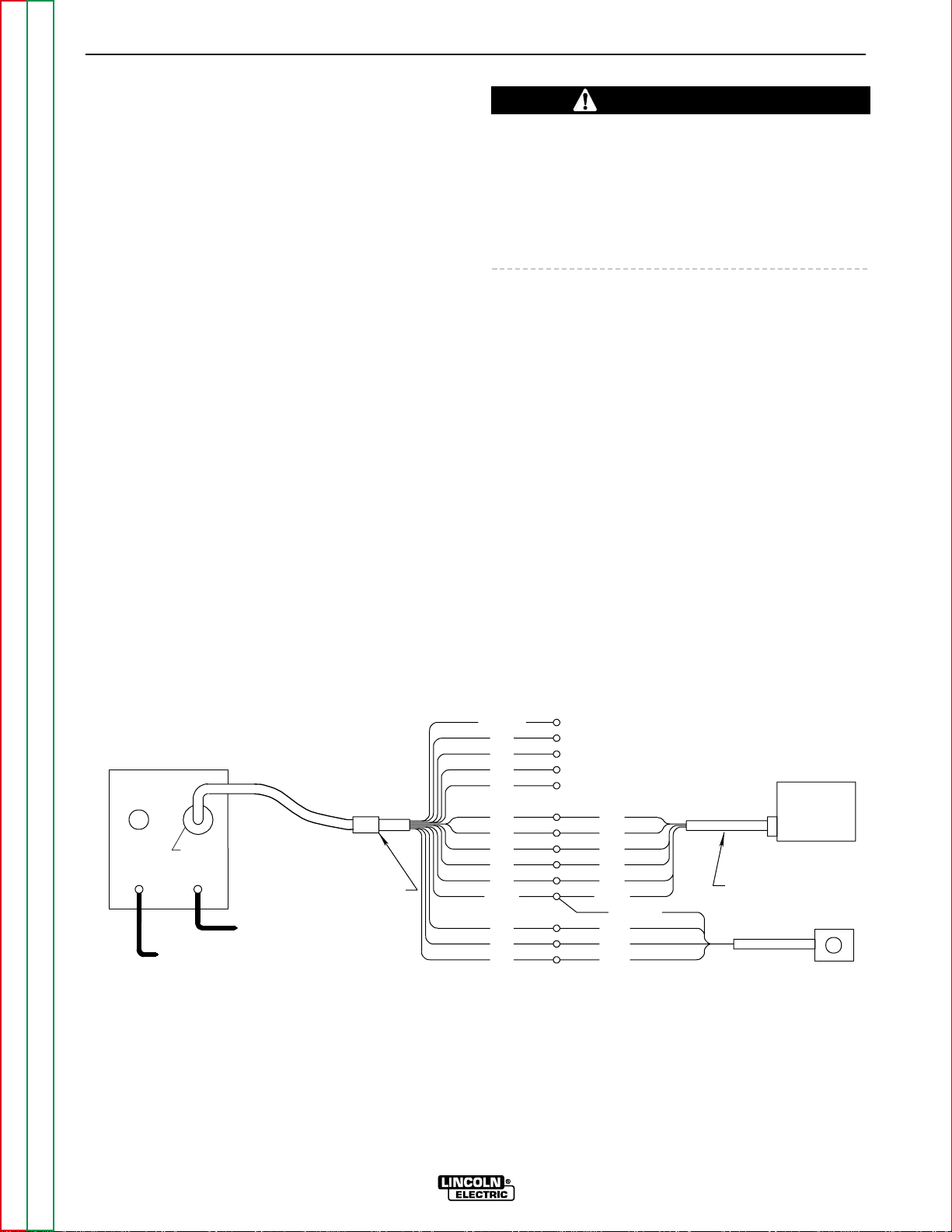
CONNECTION OF THE LN-7 TO THE
COMMANDER 500 USING K867
UNIVERSAL ADAPTER (SEE FIGURE C.1.)
1. Shut the welder off.
2. Connect the electrode cable from the LN-7 to the
“+” terminal of the welder. Connect the work cable
to the “-” terminal of the welder.
NOTE: Welding cable must be sized for current and
duty cycle of application.
NOTE: Figure C.1 shows the electrode connected for
positive polarity . To change polarity , shut the welder of f
and reverse the electrode and work cables at the
Commander 500 output terminals.
3. Connect the K867 Universal Adapter to the K291 or
K404 input cable and the 14-pin amphenol of the
Commander 500 as indicated in Figure C.1. Make
the proper connections for local or remote control
according to Figure C.1.
4. Connect the K291 or K404 input cable to the LN-7.
5. Place the IDLER switch in the HIGH position.
Any increase of the high idle engine RPM by changing
the governor setting or overriding the throttle linkage
will cause an increase in the AC auxiliary voltage. If
this voltage goes over 140 volts, wire feeder control circuits may be damaged. The engine governor setting is
preset at the factory—do not adjust above RPM specifications listed in this manual.
6. Set the VOLTMETER switch to “+” or “-” depending on the polarity chosen.
7. Set the OUTPUT RANGE switch to WIRE WELDING CV.
8. Set the WELDING TERMINALS switch to WELDING TERMINAL REMOTELY CONTROLLED.
9. Adjust wire feed speed at the LN-7.
10. Adjust the ARC CONTROL to the desired level
(“soft” or “crisp”).
C-4 C-4
ACCESSORIES
COMMANDER 500
Return to Section TOC Return to Section TOC Return to Section TOC Return to Section TOC
Return to Master TOC Return to Master TOC Return to Master TOC Return to Master TOC
CAUTION
FIGURE C.1
COMMANDER 500/LN-7 WITH K867 ADAPTER CONNECTION DIAGRAM
GND
75
76
77
GREEN
K291 OR K404
75
INPUT CABLE
76
77
K775 OPTIONAL
REMOTE CONTROL
81
42
41
31
31
32
32
2
2
4
4
21
21
GND
82
LN-7
WIRE
FEEDER
SPARE
+
ELECTRODE CABLE
TO WIRE FEED UNIT
K867 UNIVERSAL
ADAPTER PLUG
14 PIN
AMPHENOL
–
TO WORK
Page 31

C-5 C-5
ACCESSORIES
COMMANDER 500
Return to Section TOC Return to Section TOC Return to Section TOC Return to Section TOC
Return to Master TOC Return to Master TOC Return to Master TOC Return to Master TOC
CONNECTION OF THE LN-7 TO THE
COMMANDER 500 USING K584 OR
K594 INPUT CABLE ASSEMBLY
(SEE FIGURE C.2.)
1. Shut the welder off.
2. Connect the electrode cable from the LN-7 to the
“+” terminal of the welder. Connect the work cable
to the “-” terminal of the welder.
NOTE: Welding cable must be sized for current and
duty cycle of application.
NOTE: Figure C.2 shows the electrode connected for
positive polarity. To change polarity, shut the welder
off and reverse the electrode and work cables at the
Commander 500 output terminals.
3. Connect the K584-XX or K594-XX Input Cable
Assembly to the LN-7.
4. Connect the K584-XX or 594-XX input cable
assembly to the 14-pin amphenol on the
Commander 500.
5. Place the IDLER switch in the HIGH position.
Any increase of the high idle engine RPM by changing
the governor setting or overriding the throttle linkage
will cause an increase in the AC auxiliary voltage. If
this voltage goes over 140 volts, wire feeder control circuits may be damaged. The engine governor setting is
preset at the factory—do not adjust above RPM specifications listed in this manual.
6. Set the VOLTMETER switch to “+” or “-” depending on the polarity chosen.
7. Set the OUTPUT RANGE switch toWIRE WELDING CV.
7. Set the WELDING TERMINALS switch to WELDING TERMINALS REMOTELY CONTROLLED.
9. Adjust wire feed speed at the LN-7.
10. Adjust the ARC CONTROL to the desired level
(“soft” or “crisp”).
NOTE: For remote control, a K857 or K857-1 remote
control is required. Connect it to the 6-pin amphenol.
FIGURE C.2
COMMANDER 500/LN-7 WITH K584 OR K594 INPUT CABLE ASSEMBLY CONNECTION DIAGRAM
–
TO LN-7 INPUT
CABLE PLUG
AMPHENOL
OPTIONAL K857
REMOTE CONTROL
6 PIN
AMPHENOL
ELECTRODE CABLE
TO WORK
14 PIN
K584 OR K594 CONTROL CABLE
TO WIRE FEED UNIT
+
CAUTION
Page 32

C-6 C-6
ACCESSORIES
COMMANDER 500
Return to Section TOC Return to Section TOC Return to Section TOC Return to Section TOC
Return to Master TOC Return to Master TOC Return to Master TOC Return to Master TOC
CONNECTION OF THE LN-8 TO THE
COMMANDER 500 USING K867
UNIVERSAL ADAPTER (SEE FIGURE C.3.)
1. Shut the welder off.
2. Connect the electrode cable from the LN-8 to the
“+” terminal of the welder. Connect the work cable
to the “-” terminal of the welder.
NOTE: Welding cable must be sized for current and
duty cycle of application.
NOTE: Figure C.3 shows the electrode connected for
positive polarity. To change polarity, shut the welder
off and reverse the electrode and work cables at the
Commander 500 output terminals.
3. Connect the K867 Universal Adapter to the K196
input cable and the 14-pin amphenol of the
Commander 300 as indicated in Figure C.3. Make
the proper connections for local or remote control
according to Figure C.3.
4. Connect the K196 input cable to the LN-8.
5. Place the IDLER switch in the HIGH position.
Any increase of the high idle engine RPM by changing
the governor setting or overriding the throttle linkage
will cause an increase in the AC auxiliary voltage. If
this voltage goes over 140 volts, wire feeder control
circuits may be damaged. The engine governor setting is preset at the factory—do not adjust above RPM
specifications listed in this manual.
6. Set the VOLTMETER switch to “+” or “-” depending on the polarity chosen.
7. Set the OUTPUT RANGE switch to WIRE WELDING CV.
8 Set the WELDING TERMINALS switch to WELD-
ING TERMINALS REMOTELY CONTROLLED.
9. Adjust wire feed speed and voltage at the LN-8.
10. Adjust the ARC CONTROL to the desired level
(“soft” or “crisp”).
CAUTION
FIGURE C.3
COMMANDER 500/LN-8 WITH K867 ADAPTER CONNECTION DIAGRAM
75
32
31
41
42
GND
31
4
21
B
C
A
14 PIN
AMPHENOL
TO WORK
TO WORK
ELECTRODE
TO WIRE FEED UNIT
ELECTRODE CABLE
WIRE
FEEDER
K196
K867 UNIVERSAL
ADAPTER PLUG
INPUT CABLE
2
4
76
77
SPARE
82
81
21
GND
32
2
LN-8
Page 33

C-7 C-7
ACCESSORIES
COMMANDER 500
Return to Section TOC Return to Section TOC Return to Section TOC Return to Section TOC
Return to Master TOC Return to Master TOC Return to Master TOC Return to Master TOC
CONNECTION OF THE LN-8 TO THE
COMMANDER 500 USING K595 INPUT
CABLE ASSEMBLY (SEE FIGURE C.4.)
1. Shut the welder off.
2. Connect the electrode cable from the LN-8 to the
“+” terminal of the welder. Connect the work
cable to the “-” terminal of the welder.
NOTE: Welding cable must be sized for current and
duty cycle of application.
NOTE: Figure C.4 shows the electrode connected for
positive polarity. To change polarity, shut the welder
off and reverse the electrode and work cables at the
Commander 500 output terminals.
3. Connect the K595-XX Input Cable Assembly to the
LN-8.
4. Connect the K595-XX to the 14-pin amphenol on
the Commander 500.
5. Place the IDLER switch in the HIGH position.
Any increase of the high idle engine RPM by changing
the governor setting or overriding the throttle linkage
will cause an increase in the AC auxiliary voltage. If
this voltage goes over 140 volts, wire feeder control
circuits may be damaged. The engine governor setting is preset at the factory—do not adjust above RPM
specifications listed in this manual.
6. Set the VOLTMETER switch to “+” or “-” depending on the polarity chosen.
7. Set the OUTPUT RANGE switch to WIRE WELDING CV.
8. Set the WELDING TERMINALS switch to WELDING TERMINALS REMOTELY CONTROLLED.
9. Adjust wire feed speed and voltage at the LN-8.
10. Adjust the ARC CONTROL to the desired level
(“soft” or “crisp”).
FIGURE C.4
COMMANDER 500/LN-8 WITH K595 INPUT CABLE ASSEMBLY CONNECTION DIAGRAM
–
TO LN-8 INPUT
CABLE PLUG
AMPHENOL
ELECTRODE CABLE
TO WORK
14 PIN
K595 INPUT CABLE ASSEMBLY
TO WIRE FEED UNIT
+
CAUTION
Page 34

C-8 C-8
ACCESSORIES
COMMANDER 500
Return to Section TOC Return to Section TOC Return to Section TOC Return to Section TOC
Return to Master TOC Return to Master TOC Return to Master TOC Return to Master TOC
CONNECTION OF THE LN-23P TO THE
COMMANDER 500 USING K350-1
ADAPTER (SEE FIGURE C.5.)
1. Shut the welder off.
2. Connect the electrode cable from the LN-23P to
the “-” terminal of the welder. Connect the work
cable to the “+” terminal of the welder.
NOTE: Welding cable must be sized for current and
duty cycle of application.
NOTE: Figure C.5 shows the electrode connected for
negative polarity.
3. Connect the K350-1 adapter to the amphenol on
the LN-23P and the 14-pin amphenol of the
Commander 500 as indicated in Figure C.5.
4. Place the IDLER switch in the HIGH position.
Any increase of the high idle engine RPM by changing
the governor setting or overriding the throttle linkage
will cause an increase in the AC auxiliary voltage. If
this voltage goes over 140 volts, wire feeder control
circuits may be damaged. The engine governor set
ting is preset at the factory—do not adjust above RPM
specifications listed in this manual.
5. Set the VOLTMETER switch to negative.
6. Set the OUTPUT RANGE switch to WIRE WELDING CV.
7. Set the WELDING TERMINALS switch to WELDING TERMINALS REMOTELY CONTROLLED.
8. Adjust wire feed speed and voltage at the LN-23P.
CAUTION
WIRE FEEDER "B"
602
FEEDER "A"
6047576
77
14 PIN AMPHENOL
ELECTRODE
LN-23P
604
75
602
76
77
ELECTRODE
WORK
115 VAC AUXILIARY
COMMANDER 500 WITH
ELECTRODE
TO
WORK
K350-1
521
FEEDER "B"
LN-23P ADAPTER KIT
521
9 CONDUCTOR ADAPTER CABLE
LN-23P
WIRE FEEDER "A"
FIGURE C.5
COMMANDER 500/LN-23P CONNECTION DIAGRAM
Page 35

C-9 C-9
ACCESSORIES
COMMANDER 500
Return to Section TOC Return to Section TOC Return to Section TOC Return to Section TOC
Return to Master TOC Return to Master TOC Return to Master TOC Return to Master TOC
CONNECTION OF THE LN-25 TO THE
COMMANDER 500 “ACROSS THE ARC”
(SEE FIGURE C.6.)
1. Shut the welder off.
2. Connect the electrode cable from the LN-25 to the
“-” terminal of the welder. Connect the work cable
to the “+” terminal of the welder.
NOTE: Welding cable must be sized for current and
duty cycle of application.
NOTE: Figure C.6 shows the electrode connected for
negative polarity. To change polarity, shut the welder
off and reverse the electrode and work cables at the
Commander 500 output terminals. Reverse the LN-25
polarity switch.
3. Attach the single lead from the LN-25 to the work
using the spring clip on the end of the lead. This is
only a sense lead – it carries no welding current.
4. Place the IDLER switch in the AUTO position.
If you are using an LN-25 without an internal contactor,
the electrode will be HOT when the Commander 300 is
started.
5. Set the OUTPUT RANGE switch to WIRE WELDING CV.
6. Set the WELDING TERMINALS switch to WELDING TERMINALS ALWAYS ON.
7. Set the VOLTMETER switch to “+” or “-” depending on the polarity chosen.
8. Adjust wire feed speed at the LN-25.
9. Adjust the ARC CONTROL to the desired level
(“soft” or “crisp”).
FIGURE C.6
COMMANDER 500/LN-25 ACROSS THE ARC CONNECTION DIAGRAM
AMPHENOL
TO WORK
WORK CLIP LEAD
LN-25
WIRE FEEDER
OPTIONAL K444-1
REMOTE CONTROL
AMPHENOL
6 PIN
14 PIN
TO WORK
ELECTRODE CABLE
CAUTION
Page 36

Maintenance..........................................................................................................................Section D
Safety Precautions ......................................................................................................................D-2
Routine and Periodic Maintenance .............................................................................................D-2
Daily......................................................................................................................................D-2
Weekly..................................................................................................................................D-2
Engine Maintenance............................................................................................................. D-2
Change the Oil...............................................................................................................D-2
Change the Oil Filter......................................................................................................D-3
Fuel................................................................................................................................D-3
Fuel Filters .....................................................................................................................D-4
Bleeding the Fuel System..............................................................................................D-6
Air Filter..........................................................................................................................D-6
Cooling System..............................................................................................................D-7
Cooling Blower Belt........................................................................................................D-7
Engine Maintenance Schedule......................................................................................D-8
Engine Maintenance Parts .............................................................................................D-8
Battery Maintenancce........................................................................................................... D-9
Cleaning the Battery ......................................................................................................D-9
Checking Specific Gravity..............................................................................................D-9
Checking Electrolyte Level.............................................................................................D-9
Charging the Battery......................................................................................................D-9
Welder/Generator Maintenance .........................................................................................D-10
Storage.........................................................................................................................D-10
Cleaning.......................................................................................................................D-10
Nameplates..................................................................................................................D-10
Brush Removal and Replacement...............................................................................D-10
Bearings.......................................................................................................................D-10
Receptacles .................................................................................................................D-10
Cable Connections.......................................................................................................D-10
Major Component Locations.....................................................................................................D-11
Section D-1 Section D-1
TABLE OF CONTENTS
- MAINTENANCE SECTION -
COMMANDER 500
Return to Master TOC Return to Master TOC Return to Master TOC Return to Master TOC
Page 37

SAFETY PRECAUTIONS
• Have qualified personnel do all maintenance and
troubleshooting work.
• Turn the engine off before working inside the
machine.
• Remove covers or guards only when necessary to
perform maintenance and replace them when the
maintenance requiring their removal is complete.
• If covers or guards are missing from the machine, get
replacements from a Lincoln Distributor.
Read the Safety Precautions in the front of this manual and in the instruction manual for the diesel engine
used with your machine before working on the
Commander 500.
Keep all equipment safety guards, covers, and devices
in position and in good repair. Keep your hands, hair,
clothing, and tools away from the fans, and all other
moving parts when starting, operating, or repairing this
machine.
ROUTINE AND PERIODIC
MAINTENANCE
ENGINE MAINTENANCE
DAILY
a. Check the crankcase oil level.
b. Refill the fuel tank to minimize moisture condensa-
tion in the tank.
c. Open the water drain valve located on the bottom
of the water separator element one or two turns
and allow to drain into a container suitable for
diesel fuel for two to three seconds. Repeat the
above drainage procedure until diesel fuel is
detected in the container.
WEEKLY
Blow out the machine with low pressure air periodically. In particularly dirty locations, this may be required
once a week.
To prevent the engine from accidentally starting, disconnect the negative battery cable before servicing the
engine.
See Table D.1 for a summary of maintenance intervals
for the items listed below. Follow either the hourly or
the calendar intervals, whichever come first. More frequent service may be required, depending on your specific application and operating conditions.
OIL: Check the oil level after every 8 hours of operation
or daily. BE SURE TO MAINTAIN THE OIL LEVEL.
Change the oil the first time between 25 and 50 hours
of operation. Then, under normal operating conditions,
change the oil as specified in Table D.1. If the engine
is operated under heavy load or in high ambient temperatures, change the oil more frequently.
CHANGE THE OIL: Change the oil, while the engine
is still warm, as follows:
1 . Drain the oil from the drain plug located on the
engine bottom, as shown in Figure D.1. Examine
the washer and replace it if it appears damaged.
2. Replace the plug and washer and tighten firmly.
3. Remove the oil fill cap and add oil until the level
reaches the “MAX” mark on the dipstick. See
Figure D.1. Use high quality oil viscosity grade
10W40. Consult the engine manual for oil specifications for various ambient temperatures. Always
check the level with the dipstick before adding
more oil.
4. Reinstall the oil fill cap and the dipstick.
D-2 D-2
MAINTENANCE
COMMANDER 500
Return to Section TOC Return to Section TOC Return to Section TOC Return to Section TOC
Return to Master TOC Return to Master TOC Return to Master TOC Return to Master TOC
WARNING
CAUTION
Page 38

CHANGE THE OIL FILTER: Change the oil filter the
first time between 25 and 50 hours of operation. Then,
under normal operating conditions, change the oil filter
after every 250 hours of operation. If the engine is
operated under heavy load or in high ambient temperatures, change the oil filter more frequently. See
Table D.1 for recommended maintenance intervals.
See Table D.2 for replacement oil filters.
Change the oil filter as follows:
1. Remove the oil drain plug. Drain the oil from the
engine and allow the oil filter to drain. See Figure
D.1.
2. Remove the old filter (spin it off) and discard it.
Wipe off the filter mounting surface and adapter.
See Figure D.1.
3. Fill the new filter with fresh engine oil. Apply a thin
coat of new oil to the rubber gasket on the new oil
filter.
4. Spin the new filter onto the mounting adapter finger
tight until the gasket is evenly seated. Then turn it
down another 1/2 turn. Do not overtighten the new
filter.
5. Refill the engine with the proper amount and type
of oil as described in the Change the Oil section,
above. Start the engine and check for leaks
around the filter element. Correct any leaks (usually by retightening the filter, but only enough to
stop leaks) before placing the Commander 500
back in service.
6. If there are no leaks, stop the engine and recheck
the oil level. If necessary, add oil to bring the level
up to the “MAX” mark, but do not overfill. See
Figure D.1.
FUEL: At the end of each day's use, refill the fuel tank
to minimize moisture condensation and dirt contamination in the fuel line. Do not overfill; leave room for the
fuel to expand.
Refer to your engine operation manual for recommended grade of fuel.
D-3 D-3
MAINTENANCE
COMMANDER 500
Return to Section TOC Return to Section TOC Return to Section TOC Return to Section TOC
Return to Master TOC Return to Master TOC Return to Master TOC Return to Master TOC
OIL FILL CAP
DRAIN PLUG
DIPSTICK
OIL FILTER
FIGURE D.1 – OIL DRAIN AND REFILL
MAX
MIN
Page 39

FUEL FILTERS:
When working on the fuel system:
• Keep naked lights away, do not smoke !
• Do not spill fuel !
The Commander 500 is equipped with a Fuel PreFilter/Water Separator Assembly located before the
lift pump and a Secondary Fuel Filter located after the
lift pump and before the fuel injectors. The Fuel PreFilter/Water Separator is mounted to the engine block
just below the lift pump (Figure D.2). The Secondary
Fuel Filter is mounted directly to the engine just above
the oil filter (Figure D.3).
Fuel Pre-Filter/Water Separator Assembly: The prefilter is a 150 micron screen designed to protect against
gross fuel contamination of the water separator element and the Secondary Fuel Filter. If the pre-filter
becomes plugged, it may be removed, inspected,
cleaned and reinstalled. In general this only needs to
be done with each water separator element change
(about every 1,000 hrs). However, if at any time excessive fuel contamination is suspected or a sudden falloff in engine performance is detected the pre-filter
screen should be inspected and cleaned. See Figure
D.2 and follow this procedure:
1. Close the fuel shutoff valve located on the side of
the Fuel Pre-Filter/Water Separator Assembly. The
lever should be perpendicular to the hose
2. Unscrew the cap ring located on the top of the filter
header and remove the plastic center cap and Oring.
3. Remove the large white volume plug located directly under the center cap in the upper cavity of the filter header. Use a small screwdriver (or similar
device) to lift the plug part way out of the cavity to
assist with its removal.
NOTE: Be careful not to damage the pre-filter screen
with the tool used to remove the plug.
4. Using a pair of pliers, gently tug on the pull tabs of
the pre-filter screen in an alternating pattern to
gradually remove the pre-filter screen.
5. Brush off any debris and rinse in diesel fuel.
6.
Re-install the pre-filter screen into the upper cavity of
the filter header making sure the four pull tabs are
pointing up. Putting your fingers on the pull tabs,
push down evenly until the lower body of the pre-filter screen contacts the floor of the upper cav
ity.
7. Re-insert the large white volume plug into the
upper cavity.
8. Place the O-ring onto the angled seal surface of
the filter header and re-install the plastic cap. Make
sure its flange rests on the O-ring.
9. Screw on the cap ring and tighten hand tight.
10. Remember to open the fuel shutoff valve (Lever in
line with the hose) before starting the engine.
Water Separator Element: The water separator element is a two-stage filter with a special filtration/water
separating media. An expanded water reservoir provides maximum protection against water in the fuel.
The recommended change interval for the water separator element is 1,000 hours. See Figure D.2 and follow
this procedure.
1. Close the fuel shutoff valve located on the side of
the Fuel Pre-Filter/Water Separator Assembly. The
lever should be perpendicular to the hose.
2. Rotate the quick change ring (located just below fil-
ter header) clockwise approximately 1/2 turn and
slide it down and off the element.
3. Grasp the element and pull down with a slight rock-
ing motion to remove the element from the grommet
post on the bottom of the filter header.
D-4 D-4
MAINTENANCE
COMMANDER 500
Return to Section TOC Return to Section TOC Return to Section TOC Return to Section TOC
Return to Master TOC Return to Master TOC Return to Master TOC Return to Master TOC
WARNING
FIGURE D.2 – FUEL PRE-FILTER/WATER
SEP ARATOR ASSEMBLY
FUEL
SHUTOFF
VALVE
FILTER
HEADER
QUICK
CHANGE
RING
CAP
RING
Page 40

4. Slide the new element onto the grommet post on
the bottom of the filter header until the element no
longer easily moves up into the filter header. Now
rotate the element (it may take almost 1 full turn)
with a slight upward pressure until the element
begins to further engage the header. With the proper orientation now established, apply additional
pressure to seat the element in the filter header.
You should feel the element “pop” into place when
properly seated.
NOTE: The element will only go on one way. Never use
excessive force when mounting the element to the
header.
5. Slide the quick change ring up over the element and
rotate counter clockwise until an audible click or
pop is heard. If you do not hear the click, you have
not rotated the ring far enough and the element is
not in the locked position. Another indication that
the ring is in the locked position is that one set (it
doesn’t matter which one) of arrows located on the
outside of the ring should be located directly under
the air vent valve.
6 . Open the fuel shutoff valve (lever in line with the
hose).
7 . Open the air vent valve on the front of the filter
header until fuel emerges free of air bubbles. Then
close the air vent valve.
Secondary Fuel Filter: The Secondary Fuel Filter is a
spin-on cartridge type mounted directly to the engine.
Consult your engine Operator’s Manual for complete
information on service intervals and element changing
procedures.
D-5 D-5
MAINTENANCE
COMMANDER 500
Return to Section TOC Return to Section TOC Return to Section TOC Return to Section TOC
Return to Master TOC Return to Master TOC Return to Master TOC Return to Master TOC
FIGURE D.3 – SECONDARY FUEL FILTER
SECONDARY
FUEL FILTER
OIL
FILTER
Page 41

BLEEDING THE FUEL SYSTEM: In the event the
engine is operated until it runs out of fuel, you will need
to bleed the fuel system in order to start the engine.
Refer to the engine operation manual.
AIR FILTER:
Excessive air filter restriction will result in reduced
engine life.
The air filter element is a dry cartridge type. It can be
cleaned and reused. However, damaged elements
should not be reused. Stop engine after 100 hours of
running time and clean filter element. Replace the filter if necessary. Service the air cleaner regularly
according to your engine operation manual.
1. Locate the air filter canister located behind the
engine door on the top of the engine.
2. Remove the air filter element.
3. Remove loose dirt from the element with compressed air or a water hose directed from inside out.
Compressed Air: 100 psi maximum with nozzles
at least one inch away from
the element.
Water Hose: 40 psi maximum without nozzle.
4. Soak the element in a mild detergent solution for 15
minutes. Do not soak more than 24 hours. Swish
the element around in the solution to help remove
dirt.
5. Rinse elements from inside out with a gentle stream
of water (less than 40 psi) to remove all suds and
dirt.
6. Dry the element before reuse with warm air at less
than 160°F (71°C). Do not use a light bulb to dry
the element.
7. Inspect for holes and tears by looking through the
element toward a bright light. Check for damaged
gaskets or dented metal parts. Do not reuse damaged elements. Protect the element from dust and
damage during drying and storage.
8. Reinstall the air filter element.
After six cleanings, replace the air filter. A cleaned
filter will have approximately 70% of the life of a
new filter element. A restricted filter element may
not appear excessively dirty.
D-6 D-6
MAINTENANCE
COMMANDER 500
Return to Section TOC Return to Section TOC Return to Section TOC Return to Section TOC
Return to Master TOC Return to Master TOC Return to Master TOC Return to Master TOC
CAUTION
Page 42

COOLING SYSTEM: The cooling system of the Deutz
engine needs to be checked and cleaned periodically.
Consult the engine Operation Manual for the proper
frequency and procedure.
COOLING BLOWER BELT: The following procedure
should be followed to replace the cooling blower belt:
1. Allow the machine to cool.
2. Unfasten and slide the battery holder out from the
welder.
3. Disconnect the negative battery cable.
4. Remove the engine case side.
5. Loosen the air cleaner hose clamp and detach the
hose.
6. Remove the engine end panel with air box and air
cleaner attached for access to the engine.
7. See Figure D.4. Loosen the alternator mounting
bolts (1, 2, 3) and rotate the alternator toward the
engine.
8. Remove the old cooling blower belt and install a
new one.
9. Push outward on the alternator (4) and adjust the
cold belt tension to 63-73 lbs. (10-15 mm maximum deflection) midway between any two pulleys.
Tighten bolts (1), (2), (3).
10. Reinstall the air cleaner hose, engine case side,
and engine end panel. Reattach the negative battery cable. Slide in and refasten the battery holder.
11. Check the cooling blower belt tension after 100
hours of operation. (Follow seps 1-6; 9 and 10.)
D-7 D-7
MAINTENANCE
COMMANDER 500
Return to Section TOC Return to Section TOC Return to Section TOC Return to Section TOC
Return to Master TOC Return to Master TOC Return to Master TOC Return to Master TOC
FIGURE D.4 – COOLING BLOWER BELT REPLACEMENT AND ADJUSTING
1
2
4
3
Page 43

D-8 D-8
MAINTENANCE
COMMANDER 500
Return to Section TOC Return to Section TOC Return to Section TOC Return to Section TOC
Return to Master TOC Return to Master TOC Return to Master TOC Return to Master TOC
TABLE D.1
DEUTZ ENGINE MAINTENANCE SCHEDULE
FREQUENCY MAINTENANCE REQUIRED
Daily or Before
Starting Engine
• Fill fuel tank.
• Check oil level.
• Check air cleaner for dirty, loose, or damaged parts. Replace if necessary.
• Check air intake and cooling areas, clean as necessary.
1
First 50 Hours • Change engine oil.
and Every 250 • Change oil filter.
Hours Thereafter • Change fuel filter.
• Check fan belt.
Every 50 Hours • Check fuel lines and clamps.
Every 100 Hours • Check battery electrolyte level and connections.
• Clean air filter.
Refer to your Deutz engine operation manual for periodic maintenance at 100 hours and beyond.
1
125 Hours for severe conditions.
TABLE D.2
ENGINE MAINTENANCE PARTS
ITEM
Air Cleaner Element
Cooling Blower Belt
Oil Filter Element
Fuel Filter Element
Water Separator Element
Fuel Pre-Filter Screen
Battery
MANUFACTURER
Donaldson
AC
Lincoln
Gates
Deutz
Purolator
Napa
Fram
Deutz
Purolator
Napa
Fram
Lincoln
Stanadyne
Lincoln
Stanadyne
PART NUMBER
P181052
A302C
T13536-3
7585
1174418
PER2168
1820
PH3776
1174423
PC42
3358
P4102
M16890-C
31572
M16890-B
29575
BCI
Group
34
Page 44

BATTERY MAINTENANCE
GASES FROM BATTERY can explode.
• Keep sparks, flame, and cigarettes
away from battery.
BATTERY ACID can burn eyes and skin.
• Wear gloves and eye protection and be
careful when working near a battery.
Follow the instructions printed on the
battery.
To prevent EXPLOSION when:
• INSTALLING A NEW BATTERY - Disconnect the
negative cable from the old battery first and connect
to the new battery last.
• THE CORRECT POLARITY IS NEGATIVE
GROUND - Damage to the engine alternator and the
printed circuit board can result from incorrect connection.
• CONNECTING A BATTERY CHARGER
- Remove the battery from the welder by
disconnecting the negative cable first,
then the positive cable and battery
clamp. When reinstalling, connect the
negative cable last. Keep the area well
ventilated.
• USING A BOOSTER - Connect the positive lead to
the battery first, then connect the negative lead to the
engine foot.
• To prevent BATTERY BUCKLING, tighten the nuts
on the battery clamp until snug.
CLEANING THE BATTERY: Keep the battery clean
by wiping it with a damp cloth when dirty. If the terminals appear corroded, disconnect the battery cables
and wash the terminals with an ammonia solution or a
solution of 1/4 pound (0.113 kg) of baking soda and 1
quart (0.946 l) of water. Be sure the battery vent plugs
(if equipped) are tight so that none of the solution
enters the cells.
After cleaning, flush the outside of the battery, the battery compartment, and surrounding areas with clear
water. Coat the battery terminals lightly with petroleum
jelly or a non-conductive grease to retard corrosion.
Keep the battery clean and dry . Moisture accumulation
on the battery can lead to more rapid discharge and
early battery failure.
CHECKING SPECIFIC GRA VITY: Check each battery
cell with a hydrometer. A fully charged battery will have
a specific gravity of 1.260. Charge the battery if the
reading is below 1.215.
NOTE: Correct the specific gravity reading by adding
four gravity points (0.004) for every five degrees the
electrolyte temperature is above 80 degrees F (27
degrees (C). Subtract four gravity points (.004) for
every five degrees the electrolyte temperature is below
80 degrees F (27 degrees C).
CHECKING ELECTROLYTE LEVEL: If battery cells
are low, fill them to the neck of the filler hole with distilled water and recharge. If one cell is low, check for
leaks.
CHARGING THE BATTERY: The Commander 500 is
equipped with a wet charged battery. The charging
current is automatically regulated when the battery is
low (after starting the engine) to a trickle current when
the battery is fully charged.
When you charge, jump, replace, or otherwise connect
battery cables to the battery , be sure the polarity is correct. Improper polarity can damage the charging circuit. The Commander 500 charging system is NEG-
A TIVE GROUND. The positive (+) battery terminal has
a red terminal cover.
If you need to charge the battery with an external
charger, disconnect the negative cable first, then the
positive cable before you attach the charger leads.
After the battery is charged, reconnect the positive battery cable first and the negative cable last. Failure to
do so can result in damage to the internal charger components.
Follow the instructions of the battery charger manufacturer for proper charger settings and charging time.
D-9 D-9
MAINTENANCE
COMMANDER 500
Return to Section TOC Return to Section TOC Return to Section TOC Return to Section TOC
Return to Master TOC Return to Master TOC Return to Master TOC Return to Master TOC
WARNING
Page 45

WELDER/GENERATOR
MAINTENANCE
STORAGE: Store the Commander 500 in clean, dry,
protected areas.
CLEANING: Blow out the generator and controls peri-
odically with low pressure air. Do this at least once a
week in particularly dirty areas.
NAMEPLATES: Whenever routine maintenance is
performed on this machine - or at least yearly - inspect
all nameplates and labels for legibility. Replace those
which are no longer clear. Refer to the parts list for the
replacement item number.
BRUSH REMOV ALAND REPLACEMENT :It is normal
for the brushes and slip rings to wear and darken slightly. Inspect the brushes when a generator overhaul is
necessary.
Do not attempt to polish slip rings while the engine is
running.
BEARINGS: The Commander 500 is equipped with
double-shielded ball bearings having sufficient grease
to last indefinitely under normal service. Where the
welder is used constantly or in excessively dirty locations, it may be necessary to add one half ounce of
grease per year. A pad of grease one inch wide, one
inch long, and one inch high weighs approximately one
half ounce. Over-greasing is far worse than insufficient
greasing.
When greasing the bearings, keep all dirt out of the
area. Wipe the fittings completely clean and use clean
equipment. More bearing failures are caused by dirt
introduced during greasing than from insufficient
grease.
RECEPTACLES: Keep the electrical receptacles in
good condition. Remove any dirt, oil, or other debris
from their surfaces and holes.
CABLE CONNECTIONS: Check the welding cable
connections at the weld output terminals often. Be
sure that the connections are always tight.
D-10 D-10
MAINTENANCE
COMMANDER 500
Return to Section TOC Return to Section TOC Return to Section TOC Return to Section TOC
Return to Master TOC Return to Master TOC Return to Master TOC Return to Master TOC
WARNING
Page 46

D-11 D-11
MAINTENANCE
COMMANDER 500
Return to Section TOC Return to Section TOC Return to Section TOC Return to Section TOC
Return to Master TOC Return to Master TOC Return to Master TOC Return to Master TOC
12
10
8
7
9
6
5
4
3
2
1
11
FIGURE D.5 – MAJOR COMPONENT LOCATIONS
1. CASE DOOR ASSEMBLY
2. ENGINE
3. SHUT DOWN SOLENOID
4. IDLER SOLENOID
5. REAR PANELASSEMBLY
6. BASE
7. FRONT PANELASSEMBLY WITH OUTPUT PANEL
8. CONTROL PANEL
9. OUTPUT RECTIFIER BRIDGE ASSEMBLY
10. FUEL TANK
11. ROTOR/STATOR
12. CASE TOPAND SIDES
Page 47

General Description .......................................................................................................................E-2
Battery, Starter, Engine, Rotor, Stator, Pull Coil Board and Peripheral
Board – Engine Protection .....................................................................................................E-2
Weld Windings, Rectifier, Power Modules and Feedback..........................................................E-3
Analog Power Supply Board and Weld Control Board...............................................................E-4
Insulated Gate Bipolar Transistor (IGBT) Operation...................................................................E-5
Pulse Width Modulation ..............................................................................................................E-6
Chopper Technology Fundamentals ...........................................................................................E-7
Section E-1 Section E-1
TABLE OF CONTENTS
- THEORY OF OPERATION SECTION -
COMMANDER 500
Return to Master TOC Return to Master TOC Return to Master TOC Return to Master TOC
ENGINE ROTOR
STATOR
AUXILIARY WINDINGS
W
E
L
D
W
I
N
D
I
N
G
MECHANICAL
ROTATION
STARTER
ALTERNATOR
ENGINE
SENSORS
OUTPUT PROCESS/RANGE
1
2
0
V
A
C
120VAC
RECEPTACLES (2)
240VAC
RECEPTACLE
SLIP
RINGS
ANALOG
POWER SUPPLY
BOARD
ARC
WELD
CONTROL
BOARD
CONTROL
CONTROL SELECTOR
PWM
SIGNALS (2)
VOLTMETER
AMMETER
BATTERY
S
H
U
T
D
O
W
N
I
D
L
E
R
PERIPHERAL
BOARD
BATTERY
BOARD
PULL
COIL
BOARD
SOL
SOL
TO
IDLE
HOLD
COIL
42 VAC TO 14 PIN AMPHENOL
THREE-PHASE
RECTIFIER
CHOKE
IGBT
WORK
TERMINAL
ELECTRODE
TERMINAL
+
+
SHUNT
F
E
E
D
B
A
C
K
____
POWER MODULES
(2)
TO WELD
CONTROL
BOARD
FOR WIRE FEEDER
COMMANDER 500
(2) (2)
80 VDC
(2)
20 VDC
THERMAL
LIGHT
TO WELD
CONTROL
BOARD
10
VDC
10
VDC
120
VDC
1/2
BATTERY
BD
RUN/STOP
SWITCH
FIGURE E.1 – MULTI-WELD 500 BLOCK LOGIC DIAGRAM
Page 48

GENERAL DESCRIPTION
The Commander 500 is a diesel engine-driven welding
power source capable of producing 500 amps at
40VDC at a 100% duty cycle. The engine is coupled to
a brush-type alternating current generator. This AC
output is rectified and controlled by Chopper
Technology to produce DC current for multi-purpose
welding applications. The Commander 500 is also
capable of producing 12,000 watts of AC auxiliary
power at 100% duty cycle.
BATTERY, ENGINE, ROTOR,
STATOR, PULL COIL BOARD AND
PERIPHERAL BOARD – ENGINE
PROTECTION
The 12VDC battery powers the engine starter motor
and also supplies power to the Battery PC board, Pull
Coil PC board, Peripheral PC board and associated
circuitry. When the engine, which is mechanically coupled to the rotor, is started and running, the 12 VDC
battery voltage is fed through the Battery PC board to
the rotor field coil via a brush and slip ring configuration. This excitation or "flashing" voltage magnetizes
the rotor lamination. This rotating magnet induces a
voltage in the stationary windings of the main alternator stator. The stator houses a three-phase weld winding, a 120/240VAC single-phase auxiliary winding, and
a 42VAC wire feeder power winding.
The engine alternator supplies charging current for the
battery circuit. The Peripheral board monitors the
engine sensors and will shut the engine off in the event
of low oil pressure, engine over temperature, malfunction of the engine’s alternator system or a low fuel condition. The idler solenoid is mechanically connected to
the engine’s throttle linkage. If no welding or auxiliary
current is being drawn from the Commander 500, the
Pull Coil board activates the idler solenoid, which then
brings the engine to a low idle state. When output current is sensed, either weld or auxiliary, the Weld
Control PC board deactivates the idler solenoid, and
the engine returns to high RPM.
E-2 E-2
THEORY OF OPERATION
COMMANDER 500
Return to Section TOC Return to Section TOC Return to Section TOC Return to Section TOC
Return to Master TOC Return to Master TOC Return to Master TOC Return to Master TOC
FIGURE E.2 - BATTERY, ENGINE, ROTOR, STATOR, PULL COIL BOARD
AND PERIPHERAL BOARD – ENGINE PROTECTION
NOTE: Unshaded areas of Block Logic Diagram are the subject of discussion.
COMMANDER 500
1/2
BATTERY
BD
MECHANICAL
ROTATION
ALTERNATOR
RUN/STOP
SWITCH
BATTERY
STARTER
BATTERY
BOARD
120
VDC
PULL
COIL
BOARD
10
VDC
ENGINE ROTOR
ENGINE
SENSORS
S
H
U
I
T
D
D
L
O
10
VDC
E
W
R
N
SOL
TO WELD
CONTROL
SOL
BOARD
PERIPHERAL
BOARD
L
E
W
SLIP
RINGS
STATOR
AUXILIARY WINDINGS
1
2
0
V
A
C
D
W
I
N
D
I
120VAC
RECEPTACLES (2)
N
G
THREE-PHASE
RECTIFIER
+
80 VDC
ANALOG
POWER SUPPLY
BOARD
TO
IDLE
HOLD
COIL
42 VAC TO 14 PIN AMPHENOL
FOR WIRE FEEDER
240VAC
RECEPTACLE
(2) (2)
WELD
CONTROL
BOARD
ARC
THERMAL
CONTROL
LIGHT
POWER MODULES
(2)
IGBT
(2)
20 VDC
OUTPUT PROCESS/RANGE
CONTROL SELECTOR
TO WELD
CONTROL
BOARD
CHOKE
PWM
SIGNALS (2)
WORK
TERMINAL
ELECTRODE
TERMINAL
SHUNT
F
E
E
D
B
A
C
K
VOLTMETER
AMMETER
__
+
Page 49

WELD WINDINGS, RECTIFIER,
POWER MODULES AND
FEEDBACK
The three-phase stator weld windings are connected to
a three-phase rectifier bridge. The resultant DC voltage is applied to four paralleled capacitors incorporated within each of the two power modules. There are
two capacitors in each module. These capacitors function as filters and also as power supplies for the IGBTs.
See IGBT Operation in this section. The IGBTs act as
high-speed switches operating at 20KHZ. These
devices are switched on and off by the Weld Control
PC board through pulse width modulation circuitry.
See Pulse Width Modulation in this section. This
"chopped" DC output is applied through choke coils
and a shunt to the welding output terminals. The choke
functions as a current filter, and it helps to balance the
outputs of the two power modules. Free-wheeling
diodes are incorporated in the power modules to provide a current path for the stored energy in the choke
when the IGBTs are turned off. See Chopper
Technology in this section.
Output voltage and current feedback information is fed
to the Weld Control PC board. This information is
sensed from the output terminal circuits and the shunt.
E-3 E-3
THEORY OF OPERATION
COMMANDER 500
Return to Section TOC Return to Section TOC Return to Section TOC Return to Section TOC
Return to Master TOC Return to Master TOC Return to Master TOC Return to Master TOC
NOTE: Unshaded areas of Block Logic Diagram are the subject of discussion.
FIGURE E.3 - WELD WINDINGS, RECTIFIER, POWER MODULES AND FEEDBACK
ENGINE ROTOR
STATOR
AUXILIARY WINDINGS
W
E
L
D
W
I
N
D
I
N
G
MECHANICAL
ROTATION
STARTER
ALTERNATOR
ENGINE
SENSORS
OUTPUT PROCESS/RANGE
1
2
0
V
A
C
120VAC
RECEPTACLES (2)
240VAC
RECEPTACLE
SLIP
RINGS
ANALOG
POWER SUPPLY
BOARD
ARC
WELD
CONTROL
BOARD
CONTROL
CONTROL SELECTOR
PWM
SIGNALS (2)
VOLTMETER
AMMETER
BATTERY
S
H
U
T
D
O
W
N
I
D
L
E
R
PERIPHERAL
BOARD
BATTERY
BOARD
PULL
COIL
BOARD
SOL
SOL
TO
IDLE
HOLD
COIL
42 VAC TO 14 PIN AMPHENOL
THREE-PHASE
RECTIFIER
CHOKE
IGBT
WORK
TERMINAL
ELECTRODE
TERMINAL
+
+
SHUNT
F
E
E
D
B
A
C
K
____
POWER MODULES
(2)
TO WELD
CONTROL
BOARD
FOR WIRE FEEDER
COMMANDER 500
(2) (2)
80 VDC
(2)
20 VDC
THERMAL
LIGHT
TO WELD
CONTROL
BOARD
10
VDC
10
VDC
120
VDC
1/2
BATTERY
BD
RUN/STOP
SWITCH
Page 50

ANALOG CONTROL POWER
SUPPLY BOARD AND WELD
CONTROL BOARD
The Analog Power Supply PC board, which is powered
by 80 VDC derived from the filter capacitors on the
Power Modules, supplies various regulated DC voltages to operate the Weld Control PC board circuitry. It
also supplies two regulated DC voltages to operate the
IGBT driver circuitry on the two Power Modules.
The Weld Control PC board monitors the operator controls (arc control, output, and process/range selector).
It compares these commands to the current and voltage feedback information it receives from the shunt
and output terminal circuits. The circuitry on the Weld
Control PC board determines how the output should be
controlled to optimize welding results, and it sends the
correct PWM signals to the IGBT driver circuits. The
Weld Control PC board also commands the thermal
light and the voltmeter and ammeter (some items may
be optional).
E-4 E-4
THEORY OF OPERATION
COMMANDER 500
Return to Section TOC Return to Section TOC Return to Section TOC Return to Section TOC
Return to Master TOC Return to Master TOC Return to Master TOC Return to Master TOC
NOTE: Unshaded areas of Block Logic Diagram are the subject of discussion.
__
FIGURE E-4 – ANALOG CONTROL POWER SUPPLY BOARD AND WELD CONTROL BOARD
COMMANDER 500
1/2
BATTERY
BD
MECHANICAL
ROTATION
ALTERNATOR
RUN/STOP
SWITCH
BATTERY
STARTER
BATTERY
BOARD
120
VDC
PULL
COIL
BOARD
10
VDC
ENGINE ROTOR
ENGINE
SENSORS
S
H
U
I
T
D
D
L
O
10
VDC
E
W
R
N
SOL
TO WELD
CONTROL
SOL
BOARD
PERIPHERAL
BOARD
D
L
E
W
SLIP
RINGS
STATOR
AUXILIARY WINDINGS
1
2
0
V
A
C
W
I
N
D
I
N
120VAC
RECEPTACLES (2)
THREE-PHASE
G
RECEPTACLE
RECTIFIER
+
80 VDC
ANALOG
POWER SUPPLY
BOARD
TO
IDLE
HOLD
COIL
THERMAL
42 VAC TO 14 PIN AMPHENOL
FOR WIRE FEEDER
240VAC
LIGHT
(2) (2)
(2)
20 VDC
WELD
CONTROL
BOARD
ARC
CONTROL
TO WELD
CONTROL
BOARD
POWER MODULES
(2)
IGBT
CHOKE
PWM
SIGNALS (2)
OUTPUT PROCESS/RANGE
CONTROL SELECTOR
WORK
TERMINAL
ELECTRODE
TERMINAL
SHUNT
F
E
E
D
B
A
C
K
VOLTMETER
AMMETER
__
+
Page 51

INSULATED GATE BIPOLAR
TRANSISTOR (IGBT) OPERATION
An IGBT is a type of transistor. IGBTs are semiconductors well suited for high frequency switching and
high current applications.
Drawing Ashows an IGBT in a passive mode. There is
no gate signal, zero volts relative to the source, and
therefore, no current flow. The drain terminal of the
IGBT may be connected to a voltage supply; but since
there is no conduction the circuit will not supply current
to components connected to the source. The circuit is
turned off like a light switch in the OFF position.
Drawing B shows the IGBT in an active mode. When
the gate signal, a positive DC voltage relative to the
source, is applied to the gate terminal of the IGBT, it is
capable of conducting current. A voltage supply connected to the drain terminal will allow the IGBT to conduct and supply current to circuit components coupled
to the source. Current will flow through the conducting
IGBT to downstream components as long as the positive gate signal is present. This is similar to turning ON
a light switch.
E-5 E-5
THEORY OF OPERATION
COMMANDER 500
Return to Section TOC Return to Section TOC Return to Section TOC Return to Section TOC
Return to Master TOC Return to Master TOC Return to Master TOC Return to Master TOC
FIGURE E.5 – IGBT OPERATION
DRAIN
SOURCE
GATE
INJECTING LAYER
BUFFER LAYER
DRAIN DRIFT REGION
BODY REGION
p +
n +
n -
p
n + n +
DRAIN
SOURCE
GATE
INJECTING LAYER
BUFFER LAYER
DRAIN DRIFT REGION
BODY REGION
p +
n +
n -
p
n + n +
POSITIVE
VOLTAGE
APPLIED
B. ACTIVE
A. PASSIVE
Page 52

PULSE WIDTH MODULA TION
The term PULSE WIDTH MODULATION is used to
describe how much time is devoted to conduction in the
cycle. Changing the pulse width is known as MODULA TION. Pulse Width Modulation (PWM) is the varying
of the pulse width over the allowed range of a cycle to
affect the output of the machine.
MINIMUM OUTPUT
By controlling the duration of the gate signal, the IGBT
is turned on and off for different durations during a
cycle. The top drawing shows the minimum output signal possible over a 50-microsecond time period.
The positive portion of the signal represents one IGBT
group conducting for 2 microsecond. The dwell time (off
time) is 48 microseconds. Since only 2 microseconds of
the 50-microsecond time period is devoted to conducting, the output power is minimized.
MAXIMUM OUTPUT
By holding the gate signals on for 48 microseconds and
allowing only 2 microseconds of dwell time (off time)
during the 50-microsecond cycle, the output is maximized. The darkened area under the top curve can be
compared to the area under the bottom curve. The
more darkened area under the curve, the more power
is present.
E-6 E-6
THEORY OF OPERATION
COMMANDER 500
Return to Section TOC Return to Section TOC Return to Section TOC Return to Section TOC
Return to Master TOC Return to Master TOC Return to Master TOC Return to Master TOC
FIGURE E.6 – TYPICAL IGBT OUTPUTS
MINIMUM OUTPUT
(Dwell or Off Time)
sec
2
MAXIMUM OUTPUT
48
50
sec
sec
(Dwell or Off Time)
sec
48
sec
50
Page 53

CHOPPER TECHNOLOGY
FUNDAMENTALS
The new era of welding machines such as the
Commander 500, employ a technology whereby a DC
source is turned on and off (chopped up) at high speed,
then smoothed through an inductor to control an arc.
Hence the name “Chopper.” The biggest advantage of
chopper technology is the high-speed control of the
arc, similar to the inverter machines. A block diagram
for this is as follows:
In this system, the engine drives a three-phase alternator, which generates power that is rectified and
filtered to produce about 85VDC[?]. The current is
applied through a solid state switch to an inductor. By
turning the switch on and off, current in the inductor
and the arc can be controlled. The following diagram
depicts the current flow in the system when the switch
is open and closed.s
When the switch is closed, current is applied through
the inductor to the arc. When the switch opens, current
stored in the inductor sustains flow in the arc and
through the diode. The repetition rate of switch closure
is 20Khz, which allows ultra-fast control of the arc. By
varying the ratio of on time versus off time of the switch
(Duty Cycle), the current applied to the arc is controlled. This is the basis for Chopper Technology:
Controlling the switch in such a way as to produce
superior welding.
E-7 E-7
THEORY OF OPERATION
COMMANDER 500
Return to Section TOC Return to Section TOC Return to Section TOC Return to Section TOC
Return to Master TOC Return to Master TOC Return to Master TOC Return to Master TOC
EXTERNAL DC
SOURCE
INDUCTOR
AND DIODE
ARC
ARC
CONTROL
SOLID STATE
SWITCH
INDUCTOR
SWITCH
DIODE
ARC
CURRENT WITH SWITCH OPEN
CURRENT WITH SWITCH CLOSED
70-80VDC
Page 54

Troubleshooting & Repair Section......................................................................................Section F
How to Use Troubleshooting Guide ...........................................................................................F-2
PC Board Troubleshooting Procedures ......................................................................................F-3
Troubleshooting Guide ...............................................................................................................F-4
Engine Starting Diagnostic Chart..............................................................................................F-13
Start-Up and OCV Diagnostic Chart .........................................................................................F-14
Test Procedures .......................................................................................................................F-15
Case Cover Removal and Replacement Procedure...........................................................F-15
Case Front Knobs - Removal and Replacement Procedure..............................................F-18
Power Module Capacitor Discharge Procedure .................................................................F-19
Idler Solenoid Test ..............................................................................................................F-21
Shutdown Solenoid Test .....................................................................................................F-23
Engine Throttle Adjustment Test.........................................................................................F-25
Rotor Resistance Test .........................................................................................................F-29
Flashing and Rotor Voltage Test.........................................................................................F-31
Stator Voltage Test..............................................................................................................F-34
Analog Power Supply PC Board Voltage Test....................................................................F-39
Output Rectifier Bridge Test................................................................................................F-42
Power Module Test .............................................................................................................F-46
Charging Circuit Test...........................................................................................................F-50
Oscilloscope Waveforms ..........................................................................................................F-52
Normal Open Circuit Voltage Waveform (Stick) .................................................................F-53
Normal Weld Voltage Waveform (Stick CC).......................................................................F-54
Normal Weld Voltage Waveform (Wire CV)........................................................................F-55
Normal TIG Mode Voltage Waveform.................................................................................F-56
Normal Open Circuit Voltage Waveform (Wire CV Tap) .....................................................F-57
Replacement Procedures .........................................................................................................F-58
Shutdown Solenoid Removal and Replacement................................................................F-58
Power Module/Output Rectifier Bridge Assembly Removal and Replacement..................F-61
Power Module (Chopper) PC Board/Diode Module Removal and Replacement...............F-66
Output Rectifier Bridge Diode Removal and Replacement................................................F-70
Stator/Rotor Removal and Replacement............................................................................F-73
Retest After Repair ...................................................................................................................F-82
Section F-1 Section F-1
TABLE OF CONTENTS
- TROUBLESHOOTING & REPAIR SECTION -
COMMANDER 500
Return to Master TOC Return to Master TOC Return to Master TOC Return to Master TOC
Page 55

This Troubleshooting Guide is provided to help
you locate and repair possible machine malfunctions. Simply follow the three-step procedure
listed below.
Step 1. LOCATE PROBLEM (SYMPTOM). Look
under the column labeled “PROBLEM” (SYMPTOMS). This column describes possible symptoms that the machine may exhibit. Find the listing that best describes the symptom that the
machine is exhibiting. Symptoms are grouped
into four main categories: Output Problems,
Function Problems, Engine Problems and
Welding Problems.
Step 2. PERFORM EXTERNAL TESTS. The
second column, labeled “POSSIBLE AREAS OF
MISADJUSTMENT(S)”, lists the obvious external
possibilities that may contribute to the machine
symptom. Perform these tests/checks in the
order listed. In general, these tests can be conducted without removing the case cover.
Step 3. PERFORM COMPONENT TESTS. The
last column, labeled “Recommended Course of
Action” lists the most likely components that may
have failed in your machine. It also specifies the
appropriate test procedure to verify that the subject component is either good or bad. If there are
a number of possible components, check the
components in the order listed to eliminate one
possibility at a time until you locate the cause of
your problem.
All of the referenced test procedures referred to in
the Troubleshooting Guide are described in detail
at the end of this section. Refer to the
Troubleshooting and Repair Table of Contents to
locate each specific Test Procedure. All of the
referred to test points, components, terminal
strips, etc., can be found on the referenced electrical wiring diagrams and schematics. Refer to
the Electrical Diagrams Section Table of Contents
to locate the appropriate diagram.
F-2 F-2
TROUBLESHOOTING & REPAIR
COMMANDER 500
Return to Section TOC Return to Section TOC Return to Section TOC Return to Section TOC
Return to Master TOC Return to Master TOC Return to Master TOC Return to Master TOC
HOW TO USE TROUBLESHOOTING GUIDE
Service and repair should be performed by only Lincoln Electric Factory Trained Personnel.
Unauthorized repairs performed on this equipment may result in danger to the technician and machine
operator and will invalidate your factory warranty. For your safety and to avoid Electrical Shock, please
observe all safety notes and precautions detailed throughout this manual.
WARNING
CAUTION
If for any reason you do not understand the test procedures or are unable to perform the test/repairs
safely, contact the Lincoln Electric Service Department for electrical troubleshooting assistance before
you proceed. Call 1-800-833-9353.
Page 56

ELECTRIC SHOCK can kill.
Have an electrician install and service
this equipment. Turn the machine OFF
before working on equipment. Do not
touch electrically hot parts.
Sometimes machine failures appear to be due to PC
board failures. These problems can sometimes be
traced to poor electrical connections. To avoid problems when troubleshooting and replacing PC boards,
please use the following procedure:
1. Determine to the best of your technical ability that
the PC board is the most likely component causing
the failure symptom.
2. Check for loose connections at the PC board to
assure that the PC board is properly connected.
3. If the problem persists, replace the suspect PC
board using standard practices to avoid static electrical damage and electrical shock. Read the warning inside the static resistant bag and perform the
following procedures:
PC Board can be damaged by
static electricity.
• Remove your body’s static charge
before opening the static-shielding
bag. Wear an anti-static wrist
strap. For safety, use a 1 Meg
ohm resistive cord connected to a
grounded part of the equipment
frame.
• If you don’t have a wrist strap,
touch an unpainted, grounded,
part of the equipment frame. Keep
touching the frame to prevent static build-up. Be sure not to touch
any electrically live parts at the
same time.
• Tools which come in contact with the PC Board must
be either conductive, anti-static or static-dissipative.
• Remove the PC Board from the static-shielding bag
and place it directly into the equipment. Don’t set the
PC Board on or near paper, plastic or cloth which
could have a static charge. If the PC Board can’t be
installed immediately, put it back in the staticshielding bag.
• If the PC Board uses protective shorting jumpers,
don’t remove them until installation is complete.
• If you return a PC Board to The Lincoln Electric
Company for credit, it must be in the static-shielding
bag. This will prevent further damage and allow proper failure analysis.
4. Test the machine to determine if the failure symp-
tom has been corrected by the replacement PC
board.
NOTE: Allow the machine to heat up so that all electrical components can reach their operating temperature.
5. Remove the replacement PC board and substitute
it with the original PC board to recreate the original
problem.
a. If the original problem does not reappear
by substituting the original board, then the
PC board was not the problem. Continue
to look for bad connections in the control
wiring harness, junction blocks, and terminal strips.
b. If the original problem is recreated by the
substitution of the original board, then the
PC board was the problem. Reinstall the
replacement PC board and test the
machine.
6. Always indicate that this procedure was followed
when warranty reports are to be submitted.
NOTE: Following this procedure and writing on the
warranty report, “INSTALLED AND SWITCHED PC
BOARDS TO VERIFY PROBLEM,” will help avoid
denial of legitimate PC board warranty claims.
F-3 F-3
TROUBLESHOOTING & REPAIR
COMMANDER 500
Return to Section TOC Return to Section TOC Return to Section TOC Return to Section TOC
Return to Master TOC Return to Master TOC Return to Master TOC Return to Master TOC
PC BOARD TROUBLESHOOTING PROCEDURES
WARNING
ATTENTION
Static-Sensitive
Devices
Handle only at
Static-Safe
Workstations
Reusable
Container
Do Not Destroy
Page 57

Observe Safety Guidelines TROUBLESHOOTING GUIDE
detailed in the beginning of this manual.
CAUTION
If for any reason you do not understand the test procedures or are unable to perform the test/repairs safely,
contact the Lincoln Electric Service Department for electrical troubleshooting assistance before you proceed. Call
1-800-833-9353.
PROBLEMS
(SYMPTOMS)
POSSIBLE AREAS OF
MISADJUSTMENT(S)
RECOMMENDED
COURSE OF ACTION
OUTPUT PROBLEMS
Major physical or electrical damage is evident.
1. Contact your local Lincoln
Authorized Field Service
Facility.
1. Contact the Lincoln Electric
Service Department at 1-800833-9353 (WELD)
No welding output in neither Stick or CV modes. The engine operates normally. The auxiliary output is normal.
1. Place the Welding Terminals
Switch in the "ALWAYS ON"
position. If the problem is
solved, the fault may be in the
external control cable (if used),
leads #2 and #4. See the
Wiring Diagram.
2. With the engine at high idle
(1900RPM), the machine in the
Stick mode and the OUTPUT
CONTROL at maximum, check
for the presence of approximately 87VDC (open circuit voltage) at the output terminals.
3. If the correct OCV is present at
the welding output terminals
check the welding cables,
clamps and electrode holder for
loose or faulty connections.
1. Check for loose or faulty connections on the heavy current
carrying leads between the output bridge, the power modules,
the choke and the output terminals.
2. Check the Welding Terminals
Switch and associated leads.
See the Wiring Diagram.
3. Check gate leads #23, #23A,
#25 and #25A for loose or faulty
connections. See the Wiring
Diagram.
4. Perform the Stator Voltage
Test.
5. Perform the Output Rectifier
Bridge Test.
6. Perform the Power Module
Test.
7. Perform the Analog Power
Supply PC Board Test.
8. The Weld Control PC Board
may be faulty.
9. See the Start-Up and OCV
Diagnostic Chart.
F-4 F-4
TROUBLESHOOTING & REPAIR
COMMANDER 500
Return to Section TOC Return to Section TOC Return to Section TOC Return to Section TOC
Return to Master TOC Return to Master TOC Return to Master TOC Return to Master TOC
Page 58

TROUBLESHOOTING GUIDE Observe Safety Guidelines
detailed in the beginning of this manual.
CAUTION
If for any reason you do not understand the test procedures or are unable to perform the test/repairs safely,
contact the Lincoln Electric Service Department for electrical troubleshooting assistance before you proceed. Call
1-800-833-9353.
PROBLEMS
(SYMPTOMS)
POSSIBLE AREAS OF
MISADJUSTMENT(S)
RECOMMENDED
COURSE OF ACTION
OUTPUT PROBLEMS
No welding output in neither Stick
or CV modes. Also no auxiliary
power. The engine operates normally.
1. Check the brushes for wear and
proper contact to the rotor slip
rings.
2. Make sure the engine is operating at the correct high idle
speed (1900RPM).
3. Check for loose or faulty connections or leads on the auxiliary power studs in the control
box. See the Wiring Diagram.
1. Perform the Rotor Resistance
Test.
2. Perform the Flashing and
Rotor Voltage Test. If the
"flashing" voltage is not present
the Battery PC board or leads
#201 or #200 may be faulty.
See the Wiring Diagram. Also
make sure that lead #5P has
continuity (zero ohms) to
ground.
3. Check the field diode bridge and
capacitor. Replace if necessary.
4. Perform the Stator Voltage
Test.
5. See the Start-Up and OCV
Diagnostic Chart.
No auxiliary power at the receptacles. The welding output is normal
and the engine operates normally.
1. The circuit breakers may be
tripped. Reset if necessary.
2. Check for loose or faulty connections at the auxiliary receptacles.
1. Check the wiring between the
auxiliary receptacles, the connection studs in the control box,
and the main stator. See the
Wiring Diagram.
2. Perform the Stator Voltage
Test.
F-5 F-5
TROUBLESHOOTING & REPAIR
COMMANDER 500
Return to Section TOC Return to Section TOC Return to Section TOC Return to Section TOC
Return to Master TOC Return to Master TOC Return to Master TOC Return to Master TOC
Page 59

Observe Safety Guidelines TROUBLESHOOTING GUIDE
detailed in the beginning of this manual.
CAUTION
If for any reason you do not understand the test procedures or are unable to perform the test/repairs safely,
contact the Lincoln Electric Service Department for electrical troubleshooting assistance before you proceed. Call
1-800-833-9353.
PROBLEMS
(SYMPTOMS)
POSSIBLE AREAS OF
MISADJUSTMENT(S)
RECOMMENDED
COURSE OF ACTION
OUTPUT PROBLEMS
The machine has welding output
but no control of output. The auxiliary power is normal.
1. If a remote control unit is connected to the machine, check
the remote control and related
cable.
2. Check the welding and work
cables for loose or faulty connections.
1. Check the OUTPUT control
potentiometer and related
leads. See the Wiring Diagram.
2. Check the shunt and associated
feedback leads. See the Wiring
Diagram.
3. Check the voltage feedback
leads for loose or faulty connections. See the Wiring Diagram.
4. Perform the Power Module
Test.
5. The Weld Control PC board
may be faulty.
5. See the Start-Up and OCV
Diagnostic Chart.
F-6 F-6
TROUBLESHOOTING & REPAIR
COMMANDER 500
Return to Section TOC Return to Section TOC Return to Section TOC Return to Section TOC
Return to Master TOC Return to Master TOC Return to Master TOC Return to Master TOC
The machine has low welding output and low auxiliary output.
1. Check the brushes for wear and
proper contact to the slip rings.
2. The engine RPM may be low.
1. If the engine high idle speed is
low, perform the Throttle Ad-
justment Test.
2. Perform the Rotor Resistance
Test.
3. Perform the Flashing and
Rotor Voltage Test. If the rotor
voltage is low, the field capacitor
or field bridge may be faulty.
Test and replace if necessary.
See the Wiring Diagram.
4. If the engine high idle RPM is
OK, then the engine may have
lost horsepower and be in need
of major repair.
Page 60

TROUBLESHOOTING GUIDE Observe Safety Guidelines
detailed in the beginning of this manual.
CAUTION
If for any reason you do not understand the test procedures or are unable to perform the test/repairs safely,
contact the Lincoln Electric Service Department for electrical troubleshooting assistance before you proceed. Call
1-800-833-9353.
PROBLEMS
(SYMPTOMS)
POSSIBLE AREAS OF
MISADJUSTMENT(S)
RECOMMENDED
COURSE OF ACTION
FUNCTION PROBLEMS
The machine control is still active when the remote control unit is attached.
1. This is normal in TIG mode.
2. The remote control unit may be
defective.
3. Check the Amphenol connections and associated wiring.
1. Check Plug J10 on the Weld
Control PC board for loose or
faulty connections.
2. The Weld Control PC board
may be faulty.
The machine seems locked into the CC mode of operation (Stick mode).
1. Check the position of the MODE
SELECTOR switch. It must be
in the correct position for the
process being used.
2. Check that the jumper plug J3 is
properly installed in the Weld
Control PC board. (J3 has a
jumper wire from pin 1 to pin 5.)
1. Check the MODE SELECTOR
switch and associated leads.
See the Wiring Diagram.
2. The Weld Control PC board
may be faulty.
F-7 F-7
TROUBLESHOOTING & REPAIR
COMMANDER 500
Return to Section TOC Return to Section TOC Return to Section TOC Return to Section TOC
Return to Master TOC Return to Master TOC Return to Master TOC Return to Master TOC
Page 61

Observe Safety Guidelines TROUBLESHOOTING GUIDE
detailed in the beginning of this manual.
CAUTION
If for any reason you do not understand the test procedures or are unable to perform the test/repairs safely,
contact the Lincoln Electric Service Department for electrical troubleshooting assistance before you proceed. Call
1-800-833-9353.
PROBLEMS
(SYMPTOMS)
POSSIBLE AREAS OF
MISADJUSTMENT(S)
RECOMMENDED
COURSE OF ACTION
FUNCTION PROBLEMS
The wire feeder does not work when connected to the welder amphenol.
1. Check the appropriate circuit
breaker (CB1 or CB6). Reset if
tripped.
2. The wire feeder control cable
may be faulty.
3. The wire feeder may be faulty.
1. Check for the presence of
appropriate source voltage at
the 14-pin amphenol.
2. If the appropriate voltage (42
VAC or 115 VAC) is NOT present at the 14-pin amphenol,
check for loose or faulty connections. See the Wiring
Diagram.
3. Perform the Stator Voltage
Test.
The battery does not stay charged. 1. Check for loose or faulty con-
nections at the battery and
engine charging system.
2. The battery may be faulty.
Check or replace.
1. The battery charging circuit may
be faulty. Perform the
Charging Circuit Test.
F-8 F-8
TROUBLESHOOTING & REPAIR
COMMANDER 500
Return to Section TOC Return to Section TOC Return to Section TOC Return to Section TOC
Return to Master TOC Return to Master TOC Return to Master TOC Return to Master TOC
Page 62

TROUBLESHOOTING GUIDE Observe Safety Guidelines
detailed in the beginning of this manual.
CAUTION
If for any reason you do not understand the test procedures or are unable to perform the test/repairs safely,
contact the Lincoln Electric Service Department for electrical troubleshooting assistance before you proceed. Call
1-800-833-9353.
PROBLEMS
(SYMPTOMS)
POSSIBLE AREAS OF
MISADJUSTMENT(S)
RECOMMENDED
COURSE OF ACTION
ENGINE PROBLEMS
The engine will not crank when the start button is pushed.
1. Check for loose or faulty battery
cable connections.
2. The battery may be low or faulty.
3. The START button may be
faulty.
1. The starter motor or starter
solenoid may be faulty.
2. The engine may be hard to
crank due to a mechanical failure in the engine.
3. See the Engine Starting Diag-
nostic Chart.
The engine cranks but will not start. 1. Check for adequate fuel supply.
2. Make sure the fuel shut off valve
is in the open position.
3. The engine oil temperature may
be too high. Check cooling system.
4. The battery voltage may be too
low.
1. The shutdown solenoid may be
faulty. Perform the Shutdown
Solenoid Test.
2. The Peripheral PC board may
be faulty. With the RUN/STOP
switch in the "RUN" position, the
Peripheral PC board should normally supply 10VDC to the shutdown solenoid via leads #224
and #262. See the Wiring
Diagram.
3. The Pull Coil PC board may be
faulty.
4. The engine may be in need of
mechanical repair.
5. See the Engine Starting Diag-
snostic Chart.
F-9 F-9
TROUBLESHOOTING & REPAIR
COMMANDER 500
Return to Section TOC Return to Section TOC Return to Section TOC Return to Section TOC
Return to Master TOC Return to Master TOC Return to Master TOC Return to Master TOC
Page 63

Observe Safety Guidelines TROUBLESHOOTING GUIDE
detailed in the beginning of this manual.
CAUTION
If for any reason you do not understand the test procedures or are unable to perform the test/repairs safely,
contact the Lincoln Electric Service Department for electrical troubleshooting assistance before you proceed. Call
1-800-833-9353.
PROBLEMS
(SYMPTOMS)
POSSIBLE AREAS OF
MISADJUSTMENT(S)
RECOMMENDED
COURSE OF ACTION
ENGINE PROBLEMS
The engine shuts down shortly after starting.
1. Check for adequate fuel supply.
2. If any indicator light is lit when
the engine shuts down, that particular system has faulted.
Check system.
3. Check the battery cables for
loose or faulty connections.
1. Check the RUN/STOP switch
and associated leads for loose
or faulty connections.
2. Perform the Shutdown
Solenoid Test.
3. The Peripheral PC board may
be faulty. With the RUN/STOP
switch in the "RUN" position, the
Peripheral PC board should normally supply 10VDC to the shutdown solenoid via leads #224
and #262. See the Wiring
Diagram.
4. See the Engine Starting Diag-
nostic Chart.
The engine will not idle down to low speed. The machine has normal weld output and auxiliary power.
1. Make sure the IDLER switch is
in the "AUTO" position.
2. Make sure there is NOT an
external load on the weld terminals nor the auxiliary power
receptacles.
3. Check for mechanical restrictions in the solenoid linkage.
1. Perform the Idler Solenoid
Test.
2. Check leads #227, #232L,
#232M and #226A for loose or
faulty connections. See the
Wiring Diagram.
3. The Pull Coil PC board may be
faulty.
F-10 F-10
TROUBLESHOOTING & REPAIR
COMMANDER 500
Return to Section TOC Return to Section TOC Return to Section TOC Return to Section TOC
Return to Master TOC Return to Master TOC Return to Master TOC Return to Master TOC
Page 64

TROUBLESHOOTING GUIDE Observe Safety Guidelines
detailed in the beginning of this manual.
CAUTION
If for any reason you do not understand the test procedures or are unable to perform the test/repairs safely,
contact the Lincoln Electric Service Department for electrical troubleshooting assistance before you proceed. Call
1-800-833-9353.
PROBLEMS
(SYMPTOMS)
POSSIBLE AREAS OF
MISADJUSTMENT(S)
RECOMMENDED
COURSE OF ACTION
ENGINE PROBLEMS
The engine will not go to high idle
when using the auxiliary power.
Auxiliary power is normal when the
IDLER switch is in the "HIGH" position. Automatic idle function works
properly when the welding terminals are loaded.
1. Make sure the auxiliary power
leads are tight.
2. The automatic idler may not
function if the auxiliary power is
loaded to less than 150 watts.
1. Check the current sensing
toroid for loose or faulty connections. See the Wiring Diagram.
2. Make sure leads #3 and #6A
pass through the toroid twice in
opposite directions.
3. The current sensing toroid may
be faulty.
4. The Weld Control PC board
may be faulty.
The engine will not go to high idle
when attempting to weld or when
the auxiliary power is loaded.
Welding output and auxiliary power
outputs are normal when IDLER
switch is in the " HIGH" position.
1. Make sure the welding cables
and auxiliary power lead connections are tight.
1. The Weld Control PC board
may be faulty.
2. The current sensing toroid may
be faulty.
The machine goes to low idle but does not stay at low idle.
1. Make sure there is NOT an
external load (auxiliary or weld)
connected to the Commander
500.
1. The idler solenoid linkage may
be misadjusted or damaged.
2. The idler solenoid lead connections may be loose or damaged.
See the Wiring Diagram.
3. Perform the Idler Solenoid
Test.
4. The Weld Control PC board
may be faulty.
F-11 F-11
TROUBLESHOOTING & REPAIR
COMMANDER 500
Return to Section TOC Return to Section TOC Return to Section TOC Return to Section TOC
Return to Master TOC Return to Master TOC Return to Master TOC Return to Master TOC
Page 65

Observe Safety Guidelines TROUBLESHOOTING GUIDE
detailed in the beginning of this manual.
CAUTION
If for any reason you do not understand the test procedures or are unable to perform the test/repairs safely,
contact the Lincoln Electric Service Department for electrical troubleshooting assistance before you proceed. Call
1-800-833-9353.
PROBLEMS
(SYMPTOMS)
POSSIBLE AREAS OF
MISADJUSTMENT(S)
RECOMMENDED
COURSE OF ACTION
WELDING PROBLEMS
The welding arc is "cold." The engine runs normally . The auxiliary power is normal.
1. Check for loose or faulty connections at the weld output terminals and welding cable connections.
2. The welding cables may be too
long or coiled, causing an
excessive voltage drop.
3. Make sure the electrode (wire,
gas, voltage, current etc.) is correct for the process being used.
1. Check for the correct OCV at
the welding output terminals. If
the correct voltage is present at
the output terminals, check for
loose connection on the heavy
current carrying leads inside the
Commander 500. See the
Wiring Diagram.
2. If the OCV is low at the welder
output terminals, perform the
Engine Throttle Adjustment
Test.
3. Perform the Output Rectifier
Bridge Test.
4. Perform the Stator Voltage
Test.
5. Perform the Power Module
Test.
6. The Weld Control PC board
may be faulty.
F-12 F-12
TROUBLESHOOTING & REPAIR
COMMANDER 500
Return to Section TOC Return to Section TOC Return to Section TOC Return to Section TOC
Return to Master TOC Return to Master TOC Return to Master TOC Return to Master TOC
Page 66

TROUBLESHOOTING & REPAIR
F-13
COMMANDER 500
ENGINE STARTING DIAGNOSTIC CHART
F-13
Return to Section TOC Return to Section TOC Return to Section TOC Return to Section TOC
Return to Master TOC Return to Master TOC Return to Master TOC Return to Master TOC
Does the PULL COIL
read .3 ohms?
Is there FUEL?
Did 1 of the WARNING
lights come on?
Is the BATTERY
charged ENOUGH to
start the ENGINE?
Is the BATTERY
charged?
Are the BATTERY
CABLES properly
connected?
Did you hear the
FUEL SOLENOID
engage?
Did engine START?
Did engine
REMAIN running after
the 30 second
INBHIT timer?
Did the
FUEL SOLENOID
engage and REMAIN
engaged?
Did all 5 ENGINE
WARNING LIGHTS
come on?
Did all 5 ENGINE
WARNING LIGHTS
go OFF?
Is the SOLENOID
LINKAGE bound-up?
Does the HOLD COIL
read 21 ohms?
Starting
ENGINE
CORRECT
that problem.
CORRECT
that problem.
CORRECT
that problem.
Look at wires 224,
262, 405, 270, 5T,
402, 232, 236a, &
236. Also, 403,
232M or 265.
PERIPHERAL PCB or
BATTERY PCB MAY BE
BAD. ALSO, THE PULL
COIL PCB.
PERIPHERAL PCB
MAY BE BAD.
PERIPHERAL PCB
MAY BE BAD.
PERIPHERAL PCB
MAY BE BAD.
Look at wires 224,
262
Check the WARNING
LIGHTS.
Look at wires 243,
247, 248, 245,
232f, 232g, 232e,
232p, 252 & 253.
Upon placing the RUN/STOP switch in the “RUN” position, you should hear a
“click” near the engine. This is the FUEL SOLENOID engaging. It should stay
engaged. You should also see all 5 ENGINE WARNING LIGHTS come on for
about 5 seconds and then go off. Then, operate the START button. ENGINE
WARNING LIGHTS WILL COME BACK on then off again. All gauges should be
in the NORMAL operating ranges. About 30 seconds after starting the engine,
the “inihibit” circuit which prevents ENGINE SHUTDOWN will turn-off. Engine
should remain running.
Y
Y
Y
N
N
N
N
N
Y
Y
Y
Y
OK
N
Y
OK
N
OK
OK
N
N
CORRECT
that problem.
CORRECT
that problem.
MAY HAVE ENGINE
PROBLEMS.
MAY HAVE WEAK FUEL
SOLENOID OR BAD
PERIPHERAL PCB.
N
N
Y
N
N
Y
Page 67

Return to Section TOC Return to Section TOC Return to Section TOC Return to Section TOC
Return to Master TOC Return to Master TOC Return to Master TOC Return to Master TOC
TROUBLESHOOTING & REPAIR
F-14
COMMANDER 500
START-UP AND OCV DIAGNOSTIC CHART
F-14
No LOW IDLE. Is
AUX current flowing?
TWO displays
illuminated?
Is WELD current
flowing?
Are J4 & 5
plugged
in properly?
Do you have AUX.
voltage?
In TIG Mode, do you
have proper OCV?
Is the Ameter or
V meter illuminated?
Did the
ROTOR flash?
Is only ONE display
illuminated?
Does
the display inc./
dec. smoothly with the
Control Pot rotation?
Does it change?
With the
WELDING TER. SW.
in“WELD TERM. ON” did unit go
to HI IDLE/back to LO and is there
OCV present at WELD
TERMINALS?
With the
WELD. TER. SW in
“REM. CONT.” and IDLER SW.
in “AUTO”, do you have 0-8V OCV
in all modes and go
to LOW IDLE?
In CV Mode, do you
have proper OCV?
In CC Mode, do you
have proper OCV?
Go to
Engine
Starting
Diagnostic
Chart
Start
Upon starting the engine, there should be only ONE display illuminated (depending on which mode the machine is
in). The numbers in the display should increase/decrease smoothly and in a “linear” fashion with the rotation of
the Control (10K)Pot. Place the WELDING TERMINALS SW. In the “REMOTELY CONTROLLED” position and
place the IDLER SW. in the “AUTO” position. After about 12 seconds, the engine should go to LOW IDLE. Then
place the WELDING TERMINALS SW. in the “WELD TERMINALS ON” position. Engine should go back to HIGH
IDLE for 12 seconds and back to LOW IDLE and remain there. With the machine in CV Mode, you should have
an OCV range 23.7-25.2V at Min. and 75.0-78.0V at Max. In CC Mode, you should have an OCV range of 77-80V.
This WILL NOT change with the rotation of the Control Pot. In TIG Mode, you should have an OCV range of 11.0-
15.0V at Min. and 13.0-17.0V at Max. There is no need to check the PIPE OCV.
Y
Y
Y
Y
Y
CORRECT
that problem.
CORRECT
that problem.
CORRECT
that problem.
CORRECT
that problem.
CORRECT
that problem.
CORRECT
that problem.
CORRECT
that problem.
OCV too high.
CORRECT
that problem.
The numbers
“jump” as you turn
the Control Pot.
The Pot may be
bad.
The numbers DO
NOT change.
Check the Amphenols.
Insure nothing is
plugged into them. Also
check for excessive
tracking or corrosion of
the Amphenol.
Check the CONTROL
POT continuity and
continuity of wires 75,
76 & 77.
OCV is between 9-20V
in all modes. If so,
place a LIGHT load
(about 1/4 amp) across
the WELD TERM. If
the voltage goes away,
Chopper has some
slight leakage.
Continue.
OCV is higher, 70V or
more. Check
CHOPPER for a short
by unplugging J50 &
J51. This turns the
CHOPPER off. If OCV
still exists, then
CHOPPER must be
shorted or wired wrong.
No OCV. Check
CHOPPER and wires
15, 16, 17, 18, 23, 25,
23A and 25A.
No HIGH IDLE.
Check the WELD.
TERM. SW. Check
wires 2 & 4.
CORRECT
that problem.
CORRECT
that problem.
CORRECT
that problem.
CORRECT
that problem.
ANALOG POWER
SUPPLY MAY BE
BAD.
CONTROL PCB MAY
BE BAD.
N
N
N
N
OK
CONTROL PCB MAY
BE BAD.
CONTROL PCB MAY
BE BAD.
ANALOG POWER
SUPPLY MY BE BAD.
N
OK
N
N
Check for short on
any STATOR
winding. Check
WELD BRIDGE for
shorts.
Check BRUSHES,
BATTERY PCB
and wires 200,
200B, 200C, 200A,
200E, 201, 201A,
201B and 5L.
No LOW IDLE. Check Idle
Solenoid (.3 ohms for PULL
COIL and 21 ohms for
HOLD COIL) and wires 232L
& 227; 232S & 226A. Also
check mechanical linkage
going to Idle Solenoid.
Check VOLTAGE
FEEDBACK wire 208B.
Then NO displays
are illuminated.
Check wires 13 & 14.
(NOTE: Under some circumstances, the CONTROL PCB can become defective in
such a way that it causes the ANALOG POWER SUPPLY (APS) to stop working and
visa versa. If you replace the APS, it may be suggested to replace the Control PCB
too. Inspect BOTH boards. If you notice any signs of over-heated or burnt components on either board, replace BOTH boards together. IF YOU CHANGE ANY CIRCUIT BOARDS, START FROM THE BEGINNING OF THIS TEST.
N
N
Y
Y
N
Y
Y
N
N
N
N
CORRECT
that problem.
OK
V meter
N
CONTROL PCB MAY
BE BAD.
OK
Check the MODE
SELECT rotary switch
and wires 214, 218, 220
& 222.
Y
OK
A meter
Y
OK
N
Page 68

TROUBLESHOOTING & REPAIR
F-15 F-15
COMMANDER 500
CASE COVER REMOVAL AND REPLACEMENT PROCEDURE
WARNING
Service and repair should be performed by only Lincoln Electric factory trained personnel.
Unauthorized repairs performed on this equipment may result in danger to the technician
or machine operator and will invalidate your factory warranty . For your safety and to avoid
electrical shock, please observe all safety notes and precautions detailed throughout this
manual.
If for any reason you do not understand the test procedures or are unable to perform the
test/repairs safely, contact the Lincoln Electric Service Department for electrical troubleshooting assistance before you proceed. Call 1-800-833-9353 (WELD).
DESCRIPTION
This procedure will aid the technician in the removal and replacement of the case sheet
metal covers.
MATERIALS NEEDED
3/8" wrench
7/16" wrench
1/2" wrench
3/4" wrench
This procedure should take approximately 30 minutes to perform.
Return to Section TOC Return to Section TOC Return to Section TOC Return to Section TOC
Return to Master TOC Return to Master TOC Return to Master TOC Return to Master TOC
Page 69

TROUBLESHOOTING & REPAIR
F-16 F-16
COMMANDER 500
Return to Section TOC Return to Section TOC Return to Section TOC Return to Section TOC
Return to Master TOC Return to Master TOC Return to Master TOC Return to Master TOC
FIGURE F.1 – COVER REMOVAL
CASE COVER REMOVAL
AND REPLACEMENT PROCEDURE (CONTINUED)
PROCEDURE
1. Turn the engine off.
2. Using the 3/8" wrench, remove the battery
cover. Slide the battery out and disconnect
the negative battery cable.
3. Unlatch and open the engine service access
door. See Figure F.1.
4. Support the door assembly. Using the 3/8"
wrench, remove the #10-24 round head
screw, lock washer, flat washer, and nut from
the top corner of the door hinge assembly
where it attaches to the roof. Remove the
support rod.
ROUND
HEAD SCREW
LOCATION
DOOR
ASSEMBLY
LEFT
FRONT
PANEL
PROP ROD
RIGHT
FRONT
PANEL
Page 70

TROUBLESHOOTING & REPAIR
F-17 F-17
COMMANDER 500
Return to Section TOC Return to Section TOC Return to Section TOC Return to Section TOC
Return to Master TOC Return to Master TOC Return to Master TOC Return to Master TOC
FIGURE F.2 – FRONT PANEL/ROOF DETAILS
CASE COVER REMOVAL AND REPLACEMENT PROCEDURE (CONTINUED)
5. Using the 3/8" wrench, remove the four
screws from the top front of the roof assembly and the two screws from the sides of the
control box. Carefully lower the front control panel. See Figure F.2.
6. sWith the 9/16" wrench, remove the
exhaust pipe rain cap.
7. Remove the fuel tank cap, gasket, and the
lift bail cover seal.
8. With the help of an assistant, carefully
remove the roof. The door assembly
remains attached to the roof. Replace the
fuel cap.
9. With 3/8" wrench, remove the left rear panel
and the right and left front panels. See
Figure F.1.
SCREWS
FRONT
CONTROL
PANEL
SCREW
Page 71

TROUBLESHOOTING & REPAIR
F-18 F-18
COMMANDER 500
Return to Section TOC Return to Section TOC Return to Section TOC Return to Section TOC
Return to Master TOC Return to Master TOC Return to Master TOC Return to Master TOC
CASE FRONT KNOBS - REMOVAL AND REPLACEMENT PROCEDURE
Removal
Side View
(Pull)
NameplateKnob
(Push)
Removal:
(Pull)
(Push)
1. Rotate the handle portion of the knob to an approximate vertical orientation (switch detent may position
handle a few degrees off vertical). This orientation should be noted and repeated at replacement for proper
"D" shaft orientation.
2. With one hand, grasp the very bottom of vertical handle and push towards the machine nameplate and
pull down. At the same time and with the other hand, grasp the very top of the handle and pull the top edge
of the knob away from the machine nameplate. The knob should "peel" away from the nameplate and the
white nylon holding fingers of the knob base, from top to bottom.
Replacement
Rounded
Replacement:
1. If the white nylon cam of the detent mechanism is removed from it's spring loaded base by the above
procedure or intentionally, it should be returned before the knob replacement is attempted. Press the cam
into it's spring loaded holder so it sets flat and flush (Selector Switch Only).
2. Orientate the knob handle to the vertical as noted above and position the knob over the base, centered
and parallel.
3. Press the knob onto the "D" shaft and white nylon holding fingers, maintaining the parallel position.
The knob should "click" into place and should not pull off with normal operation.
Flat
Page 72

TROUBLESHOOTING & REPAIR
F-19 F-19
COMMANDER 500
POWER MODULE CAPACITOR DISCHARGE PROCEDURE
WARNING
Service and repair should be performed by only Lincoln Electric factory trained personnel.
Unauthorized repairs performed on this equipment may result in danger to the technician
or machine operator and will invalidate your factory warranty . For your safety and to avoid
electrical shock, please observe all safety notes and precautions detailed throughout this
manual.
If for any reason you do not understand the test procedures or are unable to perform the
test/repairs safely, contact the Lincoln Electric Service Department for electrical troubleshooting assistance before you proceed. Call 1-800-833-9353 (WELD).
DESCRIPTION
This procedure will insure that the large capacitors in the power modules have been discharged. This procedure should be performed whenever work is to be attempted on or
near the power modules.
MATERIALS NEEDED
3/8" Wrench
Volt/Ohmmeter
Resistor (25-1000 ohms and 25 watts minimum)
Jumper leads
This procedure should take approximately 15 minutes to perform.
Return to Section TOC Return to Section TOC Return to Section TOC Return to Section TOC
Return to Master TOC Return to Master TOC Return to Master TOC Return to Master TOC
Page 73

TROUBLESHOOTING & REPAIR
F-20 F-20
COMMANDER 500
Return to Section TOC Return to Section TOC Return to Section TOC Return to Section TOC
Return to Master TOC Return to Master TOC Return to Master TOC Return to Master TOC
FIGURE F.4 – POWER MODULE CAPACITOR TERMINAL DISCHARGE
POWER MODULE CAPACITOR DISCHARGE PROCEDURE (CONTINUED)
PROCEDURE
1. This procedure must be performed with the
engine off.
2. Using the 3/8" wrench, remove the front left
and right side panels.
3. Locate the four capacitors (two on each
side). See Figure F.4.
4. Using the resistor and jumper leads, CAREFULLY discharge the capacitor terminals.
NEVER USE A SHORTING STRAP FOR
THIS PURPOSE. DO NOT TOUCH THE
TERMINALS WITH YOUR BARE HANDS.
Repeat procedure on the other side.
5. Check the voltage across the capacitor terminals. It should be zero volts.
POWER
MODULE
CAPACITOR
TERMINALS
Page 74

TROUBLESHOOTING & REPAIR
F-21 F-21
COMMANDER 500
IDLER SOLENOID TEST
WARNING
Service and repair should be performed by only Lincoln Electric factory trained personnel.
Unauthorized repairs performed on this equipment may result in danger to the technician
or machine operator and will invalidate your factory warranty . For your safety and to avoid
electrical shock, please observe all safety notes and precautions detailed throughout this
manual.
If for any reason you do not understand the test procedures or are unable to perform the
test/repairs safely, contact the Lincoln Electric Service Department for electrical troubleshooting assistance before you proceed. Call 1-800-833-9353 (WELD).
TEST DESCRIPTION
This test will determine if the idler solenoid is capable of functioning when it is energized
with 12VDC.
MATERIALS NEEDED
External 12VDC supply ( 30 amps required)
Wiring Diagram
Volt/Ohmmeter
This procedure should take approximately 30 minutes to perform.
Return to Section TOC Return to Section TOC Return to Section TOC Return to Section TOC
Return to Master TOC Return to Master TOC Return to Master TOC Return to Master TOC
Page 75

TROUBLESHOOTING & REPAIR
F-22 F-22
COMMANDER 500
Return to Section TOC Return to Section TOC Return to Section TOC Return to Section TOC
Return to Master TOC Return to Master TOC Return to Master TOC Return to Master TOC
FIGURE F.5 – IDLER SOLENOID LEADS
IDLER SOLENOID TEST (CONTINUED)
TEST PROCEDURE
1. Turn the engine off.
2. Unlatch, lift, and secure the right side engine
service access door.
3. Locate and remove the four spade connectors that attach the idler solenoid leads to the
wiring harness leads (#226A, #232S, #227
and #232L). See Figure F.5 and the Wiring
Diagram. Remove and necessary wire
wraps.
4. Check the pull-in coil resistance (larger terminals #227 to #232L). The normal resistance is approximately 0.4 ohms.
Check the hold-in coil resistance (smaller
terminals #226A to #232S). Normal coil
resistance is approximately 20 ohms.
If either coil resistance is not correct, the
solenoid may be faulty. Replace.
5. Using the external 12VDC supply, apply
12VDC to the larger idler solenoid terminals
(#227 to #232L+). The solenoid should activate.
When the solenoid activates, remove the voltage
supply immediately. Do not leave the external
supply connected to terminals #227 and #232L for
longer than three seconds. Component damage
could result.
The solenoid should deactivate when the
12VDC is removed.
6. If the solenoid does not operate properly,
check for a mechanical restriction in the linkage.
7. Using the external 12VDC supply, apply
12VDC to the smaller idler solenoid terminals
for the hold-in coil (#226A to #232S +). Push
in the solenoid plunger. With 12 VDC applied
to the hold-in coil, the plunger should stay in
until the 12 VDC is removed.
8. If the linkage is intact and the solenoid does
not operate correctly when the 12VDC is
applied, the solenoid may be faulty. Replace.
9. Replace harness leads to the correct terminals. See Figure F.5 and the Wiring Diagram.
Replace any previously removed wire wraps.
10. Close and secure the right side engine service access door.
CAUTION
PULL-IN COIL
(LARGER TERMINALS
TOP AND BOTTOM
#227 AND #232L)
SHUTDOWN
SOLENOID
HOLD-IN COIL
(SMALLER
TERMINALS
TOP AND BOTTOM
#226A AND #232S)
IDLER
SOLENOID
Page 76

TROUBLESHOOTING & REPAIR
F-23 F-23
COMMANDER 500
SHUTDOWN SOLENOID TEST
WARNING
Service and repair should be performed by only Lincoln Electric factory trained personnel.
Unauthorized repairs performed on this equipment may result in danger to the technician
or machine operator and will invalidate your factory warranty . For your safety and to avoid
electrical shock, please observe all safety notes and precautions detailed throughout this
manual.
If for any reason you do not understand the test procedures or are unable to perform the
test/repairs safely, contact the Lincoln Electric Service Department for electrical troubleshooting assistance before you proceed. Call 1-800-833-9353 (WELD).
TEST DESCRIPTION
This test will determine if the shutdown solenoid is capable of functioning when it is energized with 12VDC.
MATERIALS NEEDED
External 12VDC supply ( 30 amps required)
Wiring Diagram
Volt/Ohmmeter
This procedure should take approximately 30 minutes to perform.
Return to Section TOC Return to Section TOC Return to Section TOC Return to Section TOC
Return to Master TOC Return to Master TOC Return to Master TOC Return to Master TOC
Page 77

TROUBLESHOOTING & REPAIR
F-24 F-24
COMMANDER 500
Return to Section TOC Return to Section TOC Return to Section TOC Return to Section TOC
Return to Master TOC Return to Master TOC Return to Master TOC Return to Master TOC
FIGURE F.6 – SHUTDOWN SOLENOID LEAD TERMINALS
SHUTDOWN SOLENOID TEST (CONTINUED)
TEST PROCEDURE
1. Turn the engine off.
2. Unlatch, lift, and secure the right side engine
service access door.
3. Locate and remove the four spade connectors that attach the shutdown solenoid leads
to the wiring harness leads (#224, #262,
#232M and #265). See Figure F.6 and the
Wiring Diagram. Remove any necessary
wire wraps.
4. Check the pull-in coil resistance (larger terminals #232M to #265). The normal resistance is approximately 0.4 ohms.
Check the hold-in coil resistance (smaller
terminals #224 to #262). Normal coil resistance is approximately 20 ohms.
If either coil resistance is not correct, the
solenoid may be faulty. Replace.
5. Using the external 12VDC supply, apply
12VDC to the larger shutdown solenoid terminals (#232M+ to #265-). The solenoid
should activate.
When the solenoid activates, remove the voltage
supply immediately. Do not leave the external
supply connected to terminals #232M and #265
for longer than three seconds. Component damage could result.
The solenoid should deactivate when the
12VDC is removed.
6. If the solenoid does not operate properly,
check for a mechanical restriction in the linkage.
7. Using the external 12VDC supply, apply
12VDC to the smaller idler solenoid terminals
for the hold-in coil (#262- to #224+). Push in
the solenoid plunger. With 12 VDC applied to
the hold-in coil, the plunger should stay in
until the 12 VDC is removed.
8. If the linkage is intact and the solenoid does
not operate correctly when the 12VDC is
applied, the solenoid may be faulty. Replace.
9. Replace harness leads to the correct terminals. See Figure F.6 and the Wiring Diagram.
Replace any previously removed wire wraps.
10. Close and secure the right side engine service access door.
CAUTION
PULL-IN COIL
(LARGER TERMINALS
EACH SIDE
#232M AND #265)
SHUTDOWN
SOLENOID
HAND-IN COIL
IDLER
SOLENOID
(SMALLER TERMINALS
EACH SIDE
#224 AND #262)
Page 78

TROUBLESHOOTING & REPAIR
F-25 F-25
COMMANDER 500
ENGINE THROTTLE ADJUSTMENT TEST
WARNING
Service and repair should be performed by only Lincoln Electric factory trained personnel.
Unauthorized repairs performed on this equipment may result in danger to the technician
or machine operator and will invalidate your factory warranty . For your safety and to avoid
electrical shock, please observe all safety notes and precautions detailed throughout this
manual.
If for any reason you do not understand the test procedures or are unable to perform the
test/repairs safely, contact the Lincoln Electric Service Department for electrical troubleshooting assistance before you proceed. Call 1-800-833-9353 (WELD).
TEST DESCRIPTION
If the machine output is low or high, this test will determine whether the engine is operating at the correct speed (RPM) during both HIGH and LOW idle conditions. Directions for
adjusting the throttle to the correct RPM are given.
MATERIALS NEEDED
Slot head screw driver
10mm Wrench
White or red marking pencil
Strobe-tach, frequency counter, or oscilloscope
This procedure should take approximately 35 minutes to perform.
Return to Section TOC Return to Section TOC Return to Section TOC Return to Section TOC
Return to Master TOC Return to Master TOC Return to Master TOC Return to Master TOC
Page 79

TROUBLESHOOTING & REPAIR
F-26 F-26
COMMANDER 500
Return to Section TOC Return to Section TOC Return to Section TOC Return to Section TOC
Return to Master TOC Return to Master TOC Return to Master TOC Return to Master TOC
FIGURE F.7 – STROBE MARK LOCATION
ENGINE THROTTLE ADJUSTMENT TEST (CONTINUED)
TEST PROCEDURE
Strobe-tach Method
1. Conduct this procedure with the engine
OFF.
2. Unlatch, lift and secure the right side engine
service access door. Perform the Case
Cover Removal and Replacement
Procedure through Step 9. (For Strobe-
Tach method only.)
3. With a white or red marking pencil, place a
mark on one of the blower paddles. See
Figure F.7 for location.
4. Connect the strobe-tach according to the
manufacturer's instructions.
5. Start the engine and direct the strobe-tach
light on the bolt head. Synchronize it to the
rotating mark.
With the machine at HIGH IDLE the tach
should read between 1890 and 1910 RPM.
With the machine at LOW IDLE the tach
should read between 1450 and 1500 RPM.
MARK BLOWER
PADDLE HERE
Page 80

TROUBLESHOOTING & REPAIR
F-27 F-27
COMMANDER 500
Return to Section TOC Return to Section TOC Return to Section TOC Return to Section TOC
Return to Master TOC Return to Master TOC Return to Master TOC Return to Master TOC
ENGINE THROTTLE ADJUSTMENT TEST (CONTINUED)
FIGURE F.8 – HIGH IDLE ADJUSTMENT
BOSCH
5 7 0 0 8 1 6
903
PES 3A 80D 410/3R
0 400 463 12
ADJUSTING
SCREW
LOCKING
NUT
FIGURE F.9 – LOW IDLE ADJUSTMENT
ADJUSTING
COLLAR
LOCKING NUT
BOSCH
5 7 0 0 8 1 6
903
PES 3A 80D 410/3R
0 400 463 12
Page 81

TROUBLESHOOTING & REPAIR
F-28 F-28
COMMANDER 500
Return to Section TOC Return to Section TOC Return to Section TOC Return to Section TOC
Return to Master TOC Return to Master TOC Return to Master TOC Return to Master TOC
ENGINE THROTTLE ADJUSTMENT TEST (CONTINUED)
6. If either of the readings is incorrect, adjust
the throttle as follows:
Adjust HIGH IDLE: Use the 10mm wrench
to loosen the locking nut. See Figure F.8
for location of the adjusting screw and locking nut. Turn the threaded screw counterclockwise to increase the HIGH IDLE
speed. Adjust the speed until the tach
reads between 1890 and 1910 RPM.
Retighten the locking nut.
Adjust LOW IDLE: First make sure there is
no load on the machine. Set the IDLE
switch to AUTO and wait for the engine to
change to low idle speed. Use the 10mm
wrench to loosen the solenoid lever arm
locking nut. See Figure F.9. Adjust the col-
lar, to change the amount of throw in the
lever arm, until the tach reads between
1450 and 1500 RPM. Retighten the locking
nut.
Frequency Counter Method
1. Plug the frequency counter into one of the
115 VAC auxiliary receptacles.
2. Start the engine and check the frequency
counter. At HIGH IDLE (1900 RPM), the
counter should read 63 Hz. At LOW IDLE
(1475 RPM), the counter should read 49
Hz. Note that these are median measurements; hertz readings may vary slightly
above or below.
3. If either of the readings is incorrect, adjust
the throttle as follows:
Adjust HIGH IDLE: Use the 10mm wrench
to loosen the locking nut. See Figure F.8
for location of the adjusting screw and locking nut. Turn the threaded screw counterclockwise to increase the HIGH IDLE
speed. Adjust the speed until the frequency reads 63 Hz. Retighten the locking nut.
Adjust LOW IDLE: First make sure there is
no load on the machine. Set the IDLE
switch to AUTO and wait for the engine to
change to low idle speed. Use the 10mm
wrench to loosen the solenoid lever arm
locking nut. See Figure F.9. Adjust the col-
lar, to change the amount of throw in the
lever arm, until the frequency reads 49 Hz.
Retighten the locking nut.
Oscilloscope Method
1. Connect the oscilloscope to the 115 VAC
receptacle, according to the manufacturer’s
instructions. At HIGH IDLE (1900 RPM),
the waveform should exhibit a period of
15.8 milliseconds. At LOW IDLE (1475
RPM), the waveform should exhibit a period
of 20.3 milliseconds. Refer to the NORMAL
OPEN CIRCUIT VOLTAGE WAVEFORM
(1 15 VAC SUPPLY) HIGH IDLE - NO LOAD
in this section of the manual.
2. If either of these waveform periods is incorrect, adjust the throttle as follows:
Adjust HIGH IDLE: Use the 10mm wrench
to loosen the locking nut. See Figure F.8
for location of the adjusting screw and locking nut. Turn the threaded screw counterclockwise to increase the HIGH IDLE
speed. Adjust the speed until the period is
15.8 milliseconds. Retighten the locking
nut.
Adjust LOW IDLE: First make sure there is
no load on the machine. Set the IDLE
switch to AUTO and wait for the engine to
change to low idle speed. Use the 10mm
wrench to loosen the solenoid lever arm
locking nut. See Figure F.9 Adjust the col-
lar, to change the amount of throw in the
lever arm, until the period is 20.3 milliseconds. Retighten the locking nut.
Page 82

TROUBLESHOOTING & REPAIR
F-29 F-29
COMMANDER 500
ROTOR RESISTANCE TEST
WARNING
Service and repair should be performed by only Lincoln Electric factory trained personnel.
Unauthorized repairs performed on this equipment may result in danger to the technician
or machine operator and will invalidate your factory warranty . For your safety and to avoid
electrical shock, please observe all safety notes and precautions detailed throughout this
manual.
If for any reason you do not understand the test procedures or are unable to perform the
test/repairs safely, contact the Lincoln Electric Service Department for electrical troubleshooting assistance before you proceed. Call 1-800-833-9353 (WELD).
TEST DESCRIPTION
This test will determine if there is a shorted winding in the rotor or if the rotor is grounded.
MATERIALS NEEDED
Ohmmeter
3/8" Wrench or socket wrench
This procedure should take approximately 15 minutes to perform.
Return to Section TOC Return to Section TOC Return to Section TOC Return to Section TOC
Return to Master TOC Return to Master TOC Return to Master TOC Return to Master TOC
Page 83

TROUBLESHOOTING & REPAIR
F-30 F-30
COMMANDER 500
Return to Section TOC Return to Section TOC Return to Section TOC Return to Section TOC
Return to Master TOC Return to Master TOC Return to Master TOC Return to Master TOC
FIGURE F.10 – ROTOR BRUSH LEADS
ROTOR RESISTANCE TEST (CONTINUED)
TEST PROCEDURE
1. Conduct this test with the engine off.
2. Using the 3/8" wrench, remove the right front
case side.
3. Using the 3/8" wrench, remove the brush
holder access panel. See Figure F.10.
4. Using the 3/8" wrench, remove the brush
holder assembly. See Figure F.10.
5. Using the ohmmeter, check the rotor winding
resistance across the slip rings. Normal
resistance is approximately 27.0 ohms.
6. Measure the resistance to ground. Place
one meter probe on either of the slip rings.
Place the other probe on any good unpainted ground. The resistance should be very
high, at least 500,000 ohms.
7. If the test does not meet the resistance
specifications, then the rotor may be faulty .
Replace.
8. Position the brush holder assembly and
attach it with two screws previously
removed. Make certain the brushes are
centered and seated properly on the slip
rings. Adjust if necessary.
9. Replace the brush holder access panel.
10. Replace the right front case cover.
SLIP
RINGS
BRUSH
HOLDER
ASSEMBLY
ACCESS PANEL
Page 84

TROUBLESHOOTING & REPAIR
F-31 F-31
COMMANDER 500
FLASHING AND ROTOR VOLTAGE TEST
WARNING
Service and repair should be performed by only Lincoln Electric factory trained personnel.
Unauthorized repairs performed on this equipment may result in danger to the technician
or machine operator and will invalidate your factory warranty . For your safety and to avoid
electrical shock, please observe all safety notes and precautions detailed throughout this
manual.
If for any reason you do not understand the test procedures or are unable to perform the
test/repairs safely, contact the Lincoln Electric Service Department for electrical troubleshooting assistance before you proceed. Call 1-800-833-9353 (WELD).
TEST DESCRIPTION
This test will determine if the correct DC voltage is being applied to the rotor at the maximum engine speed (1900 RPM). This information will aid the technician in determining if
the generator field is operating properly.
MATERIALS NEEDED
Volt/Ohmmeter
3/8" Wrench
Wiring Diagram
This procedure should take approximately 35 minutes to perform.
Return to Section TOC Return to Section TOC Return to Section TOC Return to Section TOC
Return to Master TOC Return to Master TOC Return to Master TOC Return to Master TOC
Page 85

TROUBLESHOOTING & REPAIR
F-32 F-32
COMMANDER 500
Return to Section TOC Return to Section TOC Return to Section TOC Return to Section TOC
Return to Master TOC Return to Master TOC Return to Master TOC Return to Master TOC
FIGURE F.11 – PLUG P/J52 LOCATION
FLASHING AND ROTOR VOLTAGE TEST(CONTINUED)
TEST PROCEDURE
1. Using the 3/8" wrench, remove the sheet
metal screws from the right front case side.
2. Carefully remove the right case side.
3. Set the volt/ohmmeter to the DC volts
position.
4. Locate Plug P/J52 and leads #200A and
#201A. See Figure F.11.
NOTE: Cut any cable ties necessary to perform
the test. DO NOT UNPLUG PLUG P/J52.
5. Connect the positive meter probe to lead
#200A and the negative meter probe to lead
#201A.
6. Start the engine and run it at high idle speed
(1900 RPM). Check the voltage reading on
the meter. It should read approximately
16 VDC.
PLUG P/J52
FILTER
CAPACITOR
PLUG P/J52
9
1
LEAD # 200A
10 11
2
3
12 13
4
5
FIELD DIODE
RECTIFIER BRIDGE
14 15 16
8
6
7
LEAD # 201A
Page 86

TROUBLESHOOTING & REPAIR
F-33 F-33
COMMANDER 500
Return to Section TOC Return to Section TOC Return to Section TOC Return to Section TOC
Return to Master TOC Return to Master TOC Return to Master TOC Return to Master TOC
FIGURE F.12 - FIELD DIODE RECTIFIER BRIDGE AND FILTER CAPACITOR
FLASHING AND ROTOR VOLTAGE TEST(CONTINUED)
7. If the voltage reading is low or not present,
the generator field is not functioning properly. Perform the Rotor Resistance Test.
Also check the field diode rectifier bridge, filter capacitor, and associated leads and connections. See Figure F.12 for location. See
the Wiring Diagram.
NOTE: The normal flashing voltage is approximately 9VDC. This is battery voltage, which is
processed through the Battery board. This voltage must be present during start-up to "flash"
the rotor field.
8. If the rotor voltage readings are normal, the
field circuit is functioning properly. Replace
any cable ties cut during the test. Install the
right case side.
FIELD
DIODE
FILTER
CAPACITOR
RECTIFIER
BRIDGE
Page 87

TROUBLESHOOTING & REPAIR
F-34 F-34
COMMANDER 500
STATOR VOLTAGE TEST
WARNING
Service and repair should be performed by only Lincoln Electric factory trained personnel.
Unauthorized repairs performed on this equipment may result in danger to the technician
or machine operator and will invalidate your factory warranty . For your safety and to avoid
electrical shock, please observe all safety notes and precautions detailed throughout this
manual.
If for any reason you do not understand the test procedures or are unable to perform the
test/repairs safely, contact the Lincoln Electric Service Department for electrical troubleshooting assistance before you proceed. Call 1-800-833-9353 (WELD).
TEST DESCRIPTION
This test will determine if the correct AC voltages are being generated from the stator
windings.
MATERIALS NEEDED
Volt/Ohmmeter
3/8" wrench
3/4" Wrench
This procedure should take approximately 40 minutes to perform.
Return to Section TOC Return to Section TOC Return to Section TOC Return to Section TOC
Return to Master TOC Return to Master TOC Return to Master TOC Return to Master TOC
Page 88

TROUBLESHOOTING & REPAIR
F-35 F-35
COMMANDER 500
Return to Section TOC Return to Section TOC Return to Section TOC Return to Section TOC
Return to Master TOC Return to Master TOC Return to Master TOC Return to Master TOC
FIGURE F.13 – FRONT CONTROL PANEL REMOVAL
STATOR VOLTAGE TEST (CONTINUED)
TEST PROCEDURE
1. Turn the engine off.
2. Using the 3/8" wrench, remove the four
screws holding the front control panel to the
case top and sides. See Figure F.13.
(There are two screws on the top and one
screw on each side.)
3. Carefully lower the front control panel.
4. Using the 3/8" wrench, remove the front left
and right side panels.
5. Using the 3/4" wrench, remove the internal
leads from the output terminals. Insulate the
leads.
SCREWS
FRONT
CONTROL
PANEL
SCREW
Page 89

TROUBLESHOOTING & REPAIR
F-36 F-36
COMMANDER 500
Return to Section TOC Return to Section TOC Return to Section TOC Return to Section TOC
Return to Master TOC Return to Master TOC Return to Master TOC Return to Master TOC
FIGURE F.14 – OUTPUT PANEL REMOVAL
STATOR VOLTAGE TEST (CONTINUED)
6. Using the 3/8" wrench, remove the three
screws holding the lower front panel (output
panel) to the case front assembly. Then
remove the front two screws holding the top
of the panel. These are accessed in the
control box, on the bottom at each side of
the box. See Figure F.14. Carefully move
the lower front panel to the right side. Note
the green ground lead will still be attached.
OUTPUT LEADS
(BEHIND PANEL)
OUTPUT PANEL
SCREWS
GREEN
GROUND
LEAD
Page 90

TROUBLESHOOTING & REPAIR
F-37 F-37
COMMANDER 500
Return to Section TOC Return to Section TOC Return to Section TOC Return to Section TOC
Return to Master TOC Return to Master TOC Return to Master TOC Return to Master TOC
FIGURE F.15 – AUXILIARY LEAD TEST LOCATION
STATOR VOLTAGE TEST (CONTINUED)
AUXILIARY POWER AND WELD
WINDINGS TEST
1. Start the engine and run at high idle (1900
RPM). Do not load welding or auxiliary
power.
2. Check for 115-132VAC at leads #9 to #5B.
Also check for 115-132VAC from leads #8 to
#5E. See Figure F.15 and the Wiring
Diagram.
3. Check for 230 to 264VAC at leads #11 to
#12. See Figure F.15 and the Wiring
Diagram.
AUXILIARY
LEADS #5B, #5E,
#8, #9, #11, #12
(BEHIND PANEL)
Page 91

TROUBLESHOOTING & REPAIR
F-38 F-38
COMMANDER 500
Return to Section TOC Return to Section TOC Return to Section TOC Return to Section TOC
Return to Master TOC Return to Master TOC Return to Master TOC Return to Master TOC
FIGURE F.16 – OUTPUT RECTIFIER DIODE BRIDGE
STATOR VOLTAGE TEST (CONTINUED)
4. Locate the weld winding leads connected to
the three-phase output rectifier diode bridge.
See Figure F.16.
5. Check for approximately 68VAC from W1 to
W2. Also check from W3 to W4 and from
W5 to W6.
6. If any of these voltages are low or missing
perform the Flashing and Rotor Voltage
Test and also the Rotor Resistance Test.
7. Also check leads #6F and #5P for loose or
faulty connections to the field bridge. See
the Wiring Diagram.
8. If the tests in Steps 6 and 7 are OK and the
stator voltages are low or missing, the stator
may be faulty.
9. Replace the lower front panel and output
leads.
10. Replace the upper control panel and
secure.
11. Replace the front left and right case sides.
WELD WINDING
LEAD CONNECTIONS
W6
W2
W4
W1
W3
W5
Page 92

TROUBLESHOOTING & REPAIR
F-39 F-39
COMMANDER 500
ANALOG POWER SUPPLY PC BOARD VOLTAGE TEST
WARNING
Service and repair should be performed by only Lincoln Electric factory trained personnel.
Unauthorized repairs performed on this equipment may result in danger to the technician
or machine operator and will invalidate your factory warranty . For your safety and to avoid
electrical shock, please observe all safety notes and precautions detailed throughout this
manual.
If for any reason you do not understand the test procedures or are unable to perform the
test/repairs safely, contact the Lincoln Electric Service Department for electrical troubleshooting assistance before you proceed. Call 1-800-833-9353 (WELD).
TEST DESCRIPTION
This test will determine if the Analog Power Supply PC board is receiving and passing the
proper signal voltages.
MATERIALS NEEDED
Analog Volt/Ohmmeter
Wiring Diagram
This procedure should take approximately 30 minutes to perform.
Return to Section TOC Return to Section TOC Return to Section TOC Return to Section TOC
Return to Master TOC Return to Master TOC Return to Master TOC Return to Master TOC
Page 93

TROUBLESHOOTING & REPAIR
F-40 F-40
COMMANDER 500
Return to Section TOC Return to Section TOC Return to Section TOC Return to Section TOC
Return to Master TOC Return to Master TOC Return to Master TOC Return to Master TOC
FIGURE F.17 – ANALOG POWER SUPPLY PC BOARD
ANALOG POWER SUPPLY PC BOARD VOLTAGE TEST (CONTINUED)
TEST PROCEDURE
1. Turn the engine off.
2. Perform the Case Cover Removal proce-
dure.
3. Locate plugs J41 and J42 from the Analog
Power Supply PC board. See Figure F.17.
4. Start the engine and run it at high idle (1900
RPM) with no load.
5. Check for the correct input voltage:
a. Set the volt/ohmmeter to the Volts DC
position.
b. Place the negative probe on J41 pin 2
and the positive probe on J41 pin 1.
c. The reading should be between 75 and
85 VDC.
If the reading is not correct, the stator output may be incorrect, the rectifier output
may be incorrect, the power capacitors may
be faulty, or the Power Module PC board
may be faulty. Perform the Stator Voltage
Test, the Output Rectifier Bridge Test,
and the Power Module PC Board Test.
The capacitors C1, C2, C3 or C4 may be
faulty. Test and replace if necessary.
6. Check for the correct output voltage readings per Table F.1. If any of the readings
are not correct, the Analog Power Supply
PC board may be faulty.
7. When finished testing, perform the Case
Cover Replacement procedure.
1
3
4
J41
6
7
8
9
10
J42
2
1
2
3
4
5
CONTROL
CIRCUIT
INPUT
POWER
13 1J41 to POS TERMINAL ON C2 - 85V SUPPLY
14 2J41 to NEG TERMINAL ON C2 - 85V SUPPLY
PCB2
ANALOG
POWER
J41
PC BOARD
J42
Page 94

TROUBLESHOOTING & REPAIR
F-41 F-41
COMMANDER 500
Return to Section TOC Return to Section TOC Return to Section TOC Return to Section TOC
Return to Master TOC Return to Master TOC Return to Master TOC Return to Master TOC
TABLE F.1
ANALOG CONTROL POWER SUPPLY PC BOARD VOLTAGE TABLE
Test Points Component Tested Voltage Reading
1J42 to 6J42 Chopper Power Supply +20 VDC
3J42 to 8J42 Chopper Power Supply +20 VDC
2J42 to 7J42 Weld Control PC Board Power Supply +5 VDC
5J42 to 7J42 Weld Control PC Board Power Supply +15 VDC
9J42 to 7J42 Weld Control PC Board Power Supply -15 VDC
10J42 to 4J42 Weld Control PC Board Power Supply +15 VDC
ANALOG CONTROL POWER SUPPLY PC BOARD TEST (CONTINUED)
Page 95

TROUBLESHOOTING & REPAIR
F-42 F-42
COMMANDER 500
OUTPUT RECTIFIER BRIDGE TEST
WARNING
Service and repair should be performed by only Lincoln Electric factory trained personnel.
Unauthorized repairs performed on this equipment may result in danger to the technician
or machine operator and will invalidate your factory warranty . For your safety and to avoid
electrical shock, please observe all safety notes and precautions detailed throughout this
manual.
If for any reason you do not understand the test procedures or are unable to perform the
test/repairs safely, contact the Lincoln Electric Service Department for electrical troubleshooting assistance before you proceed. Call 1-800-833-9353 (WELD).
TEST DESCRIPTION
This test will determine if there are faulty diodes in the output rectifier bridge.
MATERIALS NEEDED
Volt/Ohmmeter (Diode Tester)
3/8" Wrench
7/16" Wrench
3/4" Wrench
Wiring Diagram
This procedure should take approximately 40 minutes to perform.
Return to Section TOC Return to Section TOC Return to Section TOC Return to Section TOC
Return to Master TOC Return to Master TOC Return to Master TOC Return to Master TOC
Page 96

TROUBLESHOOTING & REPAIR
F-43 F-43
COMMANDER 500
Return to Section TOC Return to Section TOC Return to Section TOC Return to Section TOC
Return to Master TOC Return to Master TOC Return to Master TOC Return to Master TOC
FIGURE F.18 – FRONT CONTROL PANEL REMOVAL
OUTPUT RECTIFIER BRIDGE TEST(CONTINUED)
TEST PROCEDURE
1. Turn the engine off.
2. Using the 3/8" wrench remove the screws
holding the front control panel to the case
top and sides. See Figure F.18. (There are
two screws on the top and one screw on
each side.)
3. Carefully lower the front control panel.
4. Using the 3/8" wrench, remove the front left
and right side panels.
5. Perform the Power Module Capacitor
Discharge Procedure.
6. Using the 3/4" wrench, remove the internal
leads from the output terminals. Insulate the
leads.
SCREWS
FRONT
CONTROL
PANEL
SCREW
Page 97

TROUBLESHOOTING & REPAIR
F-44 F-44
COMMANDER 500
Return to Section TOC Return to Section TOC Return to Section TOC Return to Section TOC
Return to Master TOC Return to Master TOC Return to Master TOC Return to Master TOC
FIGURE F.19 – OUTPUT PANEL REMOVAL
OUTPUT RECTIFIER BRIDGE TEST(CONTINUED)
7. Using the 3/8" wrench, remove the three
screws holding the lower front panel (output
panel) to the case front assembly. Then
remove the front two screws holding the top
of the panel. These are accessed in the
control box, on the bottom at each side of
the box. Using the 7/16" wrench, disconnect the green ground lead. See Figure
F.19. Carefully move the lower front panel
to the right side.
8. Disconnect Bypass PC board leads #206B
and #208 from their in-line connectors.
OUTPUT LEADS
(BEHIND PANEL)
OUTPUT PANEL
SCREWS
GREEN
GROUND
LEAD
Page 98

TROUBLESHOOTING & REPAIR
F-45 F-45
COMMANDER 500
Return to Section TOC Return to Section TOC Return to Section TOC Return to Section TOC
Return to Master TOC Return to Master TOC Return to Master TOC Return to Master TOC
FIGURE F.20 – DIODE LEAD REMOVAL
OUTPUT RECTIFIER BRIDGE TEST(CONTINUED)
9. Using the 7/16" wrench, remove the stator
leads and diode pigtail leads from the three
studs. Label the leads for reassembly.
Note leads and pigtail placement for
reassembly. See Figure F.20.
10. Electrically isolate the six diode pigtail
leads by carefully bending them out into
"free air."
11. With an ohmmeter or diode tester, check
each of the six diodes from their pigtails to
their respective heat sinks.
12. Reverse the tester leads and check the
diodes again. Diodes should have a low
resistance in one polarity and a very high
resistance in the opposite polarity.
13. Replace any "shorted" or "open" diode as
the tests indicate. See the Diode Removal
and Replacement Procedure.
14. Replace the pigtails and stator leads onto
the correct studs. Assemble the washers
and nuts.
15. Replace the lower front panel and output
leads.
16. Replace the upper control panel and
secure.
17. Replace the front left and right case sides.
WELD WINDING
LEAD CONNECTIONS
W6
W2
W4
W1
W3
W5
Page 99

TROUBLESHOOTING & REPAIR
F-46 F-46
COMMANDER 500
POWER MODULE TEST
WARNING
Service and repair should be performed by only Lincoln Electric factory trained personnel.
Unauthorized repairs performed on this equipment may result in danger to the technician
or machine operator and will invalidate your factory warranty . For your safety and to avoid
electrical shock, please observe all safety notes and precautions detailed throughout this
manual.
If for any reason you do not understand the test procedures or are unable to perform the
test/repairs safely, contact the Lincoln Electric Service Department for electrical troubleshooting assistance before you proceed. Call 1-800-833-9353 (WELD).
TEST DESCRIPTION
This test will help determine if the power modules are shorted. This is a resistance test,
not a voltage test. This test will only help diagnose a problem in the "power" section of
the module. Other PC board components could be faulty.
MATERIALS NEEDED
Volt/Ohmmeter (Analog)
3/8" Wrench
7/16" Wrench
3/4" Wrench
This procedure should take approximately 45 minutes to perform.
Return to Section TOC Return to Section TOC Return to Section TOC Return to Section TOC
Return to Master TOC Return to Master TOC Return to Master TOC Return to Master TOC
Page 100

TROUBLESHOOTING & REPAIR
F-47 F-47
COMMANDER 500
Return to Section TOC Return to Section TOC Return to Section TOC Return to Section TOC
Return to Master TOC Return to Master TOC Return to Master TOC Return to Master TOC
FIGURE F.21 – POWER MODULE CAPACITOR LEADS (LEFT SIDE)
POWER MODULE TEST (CONTINUED)
TEST PROCEDURE
1. Turn the engine off.
2. Perform the Case Cover Removal proce-
dure.
3. Perform the Power Module Capacitor
Discharge procedure.
4. Using the 7/16" wrench, loosen the nuts on
the positive terminals of the power capacitors. Then remove the nuts, lock washers,
and flat washers from the terminals where
the positive straps connect to the power
module PC board. Flip the straps out of the
way. Also remove diode lead D3 (if working
on right side power module) or D4 (if working on left side power module). See Figure
F.21.
5. Using the 7/16" wrench, remove the flex
leads W9 and W10 (left side) or W7 and W8
(right side) from the Power Module PC board
terminals.
6. Using the 7/16" wrench, remove the negative jumper strap attaching the power capacitors to the Power Module PC board.
NOTE: Make sure the bolts do not fall back
against the heat sink.
TEMPERATURE
SWITCH
W9
W10
POWER
MODULE
PC BOARD
POSITIVE (+)
STRAP
DIODE
LEAD D4
POSITIVE (+)
STRAP
 Loading...