

Page 1

Return to Master TOC Return to Master TOC Return to Master TOC Return to Master TOC
View Safety Info View Safety Info View Safety Info View Safety Info
SVM148-B
February, 2004
For use with machine code numbers 10399 thru 10850
RANGER 300 D and 300 DLX
TM
RETURN TO MAIN INDEX
SERVICE MANUAL
Safety Depends on You
Lincoln arc welding and cutting
equipment is designed and built
with safety in mind. However, your
overall safety can be increased by
proper installation ... and thoughtful operation on your part. DO
NOT INSTALL, OPERATE OR
REPAIR THIS EQUIPMENT
WITHOUT READING THIS MANUAL AND THE SAFETY PRECAUTIONS CONTAINED
THROUGHOUT. And, most
importantly, think before you act
and be careful.
• Sales and Service through Subsidiaries and Distributors Worldwide •
Cleveland, Ohio 44117-1199 U.S.A. TEL: 216.481.8100 FAX: 216.486.1751 WEB SITE: www.lincolnelectric.com
• World's Leader in Welding and Cutting Products •
Copyright © 2004 Lincoln Global Inc.
Page 2
Return to Master TOC Return to Master TOC Return to Master TOC Return to Master TOC
SAFETY
i i
RANGER 300 D AND 300 DLX
FOR ENGINE
powered equipment.
1.a. Turn the engine off before troubleshooting and maintenance
work unless the maintenance work requires it to be running.
____________________________________________________
1.b.Operate engines in open, well-ventilated
areas or vent the engine exhaust fumes
outdoors.
____________________________________________________
1.c. Do not add the fuel near an open flame welding arc or when the engine is running. Stop
the engine and allow it to cool before refueling to prevent spilled fuel from vaporizing on
contact with hot engine parts and igniting. Do
not spill fuel when filling tank. If fuel is spilled,
wipe it up and do not start engine until fumes
have been eliminated.
____________________________________________________
1.d. Keep all equipment safety guards, covers and devices in position and in good repair.Keep hands, hair, clothing and tools
away from V-belts, gears, fans and all other moving parts
when starting, operating or repairing equipment.
____________________________________________________
1.e. In some cases it may be necessary to remove safety
guards to perform required maintenance. Remove
guards only when necessary and replace them when the
maintenance requiring their removal is complete.
Always use the greatest care when working near moving
parts.
___________________________________________________
1.f. Do not put your hands near the engine fan.
Do not attempt to override the governor or
idler by pushing on the throttle control rods
while the engine is running.
___________________________________________________
1.g. To prevent accidentally starting gasoline engines while
turning the engine or welding generator during maintenance
work, disconnect the spark plug wires, distributor cap or
magneto wire as appropriate.
ARC WELDING CAN BE HAZARDOUS. PROTECT YOURSELF AND OTHERS FROM POSSIBLE SERIOUS INJURY OR DEATH.
KEEP CHILDREN AWAY. PACEMAKER WEARERS SHOULD CONSULT WITH THEIR DOCTOR BEFORE OPERATING.
Read and understand the following safety highlights. For additional safety information, it is strongly recommended that you
purchase a copy of “Safety in Welding & Cutting - ANSI Standard Z49.1” from the American Welding Society, P.O. Box 351040,
Miami, Florida 33135 or CSA Standard W117.2-1974. AFree copy of “Arc Welding Safety” booklet E205 is available from the
Lincoln Electric Company, 22801 St. Clair Avenue, Cleveland, Ohio 44117-1199.
BE SURE THAT ALL INSTALLATION, OPERATION, MAINTENANCE AND REPAIR PROCEDURES ARE
PERFORMED ONLY BY QUALIFIED INDIVIDUALS.
WARNING
Mar ‘95
ELECTRIC AND
MAGNETIC FIELDS
may be dangerous
2.a. Electric current flowing through any conductor causes
localized Electric and Magnetic Fields (EMF). Welding
current creates EMF fields around welding cables and
welding machines
2.b. EMF fields may interfere with some pacemakers, and
welders having a pacemaker should consult their physician
before welding.
2.c. Exposure to EMF fields in welding may have other health
effects which are now not known.
2.d. All welders should use the following procedures in order to
minimize exposure to EMF fields from the welding circuit:
2.d.1.
Route the electrode and work cables together - Secure
them with tape when possible.
2.d.2. Never coil the electrode lead around your body.
2.d.3. Do not place your body between the electrode and
work cables. If the electrode cable is on your right
side, the work cable should also be on your right side.
2.d.4. Connect the work cable to the workpiece as close as
possible to the area being welded.
2.d.5. Do not work next to welding power source.
1.h. To avoid scalding, do not remove the
radiator pressure cap when the engine is
hot.
CALIFORNIA PROPOSITION 65 WARNINGS
Diesel engine exhaust and some of its constituents
are known to the State of California to cause cancer, birth defects, and other reproductive harm.
The engine exhaust from this product contains
chemicals known to the State of California to cause
cancer, birth defects, or other reproductive harm.
The Above For Diesel Engines
The Above For Gasoline Engines
Page 3
Return to Master TOC Return to Master TOC Return to Master TOC Return to Master TOC
SAFETY
ii ii
RANGER 300 D AND 300 DLX
ARC RAYS can burn.
4.a. Use a shield with the proper filter and cover
plates to protect your eyes from sparks and
the rays of the arc when welding or observing
open arc welding. Headshield and filter lens
should conform to ANSI Z87. I standards.
4.b. Use suitable clothing made from durable flame-resistant
material to protect your skin and that of your helpers from
the arc rays.
4.c. Protect other nearby personnel with suitable, non-flammable
screening and/or warn them not to watch the arc nor expose
themselves to the arc rays or to hot spatter or metal.
ELECTRIC SHOCK can kill.
3.a. The electrode and work (or ground) circuits
are electrically “hot” when the welder is on.
Do not touch these “hot” parts with your bare
skin or wet clothing. Wear dry, hole-free
gloves to insulate hands.
3.b. Insulate yourself from work and ground using dry insulation.
Make certain the insulation is large enough to cover your full
area of physical contact with work and ground.
In addition to the normal safety precautions, if welding
must be performed under electrically hazardous
conditions (in damp locations or while wearing wet
clothing; on metal structures such as floors, gratings or
scaffolds; when in cramped positions such as sitting,
kneeling or lying, if there is a high risk of unavoidable or
accidental contact with the workpiece or ground) use
the following equipment:
• Semiautomatic DC Constant Voltage (Wire) Welder.
• DC Manual (Stick) Welder.
• AC Welder with Reduced Voltage Control.
3.c. In semiautomatic or automatic wire welding, the electrode,
electrode reel, welding head, nozzle or semiautomatic
welding gun are also electrically “hot”.
3.d. Always be sure the work cable makes a good electrical
connection with the metal being welded. The connection
should be as close as possible to the area being welded.
3.e. Ground the work or metal to be welded to a good electrical
(earth) ground.
3.f.
Maintain the electrode holder, work clamp, welding cable and
welding machine in good, safe operating condition. Replace
damaged insulation.
3.g. Never dip the electrode in water for cooling.
3.h. Never simultaneously touch electrically “hot” parts of
electrode holders connected to two welders because voltage
between the two can be the total of the open circuit voltage
of both welders.
3.i. When working above floor level, use a safety belt to protect
yourself from a fall should you get a shock.
3.j. Also see Items 6.c. and 8.
FUMES AND GASES
can be dangerous.
5.a.Welding may produce fumes and gases
hazardous to health. Avoid breathing these
fumes and gases.When welding, keep
your head out of the fume. Use enough
ventilation and/or exhaust at the arc to keep
fumes and gases away from the breathing zone. When
welding with electrodes which require special
ventilation such as stainless or hard facing (see
instructions on container or MSDS) or on lead or
cadmium plated steel and other metals or coatings
which produce highly toxic fumes, keep exposure as
low as possible and below Threshold Limit Values (TLV)
using local exhaust or mechanical ventilation. In
confined spaces or in some circumstances, outdoors, a
respirator may be required. Additional precautions are
also required when welding on galvanized steel.
5.b.
Do not weld in locations near chlorinated hydrocarbon
vapors
coming from degreasing, cleaning or spraying operations.
The heat and rays of the arc can react with solvent vapors
to
form phosgene, a highly toxic gas, and other irritating
products.
5.c. Shielding gases used for arc welding can displace air and
cause injury or death. Always use enough ventilation,
especially in confined areas, to insure breathing air is safe.
5.d. Read and understand the manufacturer’s instructions for this
equipment and the consumables to be used, including the
material safety data sheet (MSDS) and follow your
employer’s safety practices. MSDS forms are available from
your welding distributor or from the manufacturer.
5.e. Also see item 1.b.
Mar ‘95
Page 4
Return to Master TOC Return to Master TOC Return to Master TOC Return to Master TOC
SAFETY
iii iii
RANGER 300 D AND 300 DLX
FOR ELECTRICALLY
powered equipment.
8.a. Turn off input power using the disconnect
switch at the fuse box before working on
the equipment.
8.b. Install equipment in accordance with the U.S. National
Electrical Code, all local codes and the manufacturer’s
recommendations.
8.c. Ground the equipment in accordance with the U.S. National
Electrical Code and the manufacturer’s recommendations.
CYLINDER may explode
if damaged.
7.a. Use only compressed gas cylinders
containing the correct shielding gas for the
process used and properly operating
regulators designed for the gas and
pressure used. All hoses, fittings, etc. should be suitable for
the application and maintained in good condition.
7.b. Always keep cylinders in an upright position securely
chained to an undercarriage or fixed support.
7.c. Cylinders should be located:
•Away from areas where they may be struck or subjected to
physical damage.
•A safe distance from arc welding or cutting operations and
any other source of heat, sparks, or flame.
7.d. Never allow the electrode, electrode holder or any other
electrically “hot” parts to touch a cylinder.
7.e. Keep your head and face away from the cylinder valve outlet
when opening the cylinder valve.
7.f. Valve protection caps should always be in place and hand
tight except when the cylinder is in use or connected for
use.
7.g. Read and follow the instructions on compressed gas
cylinders, associated equipment, and CGA publication P-l,
“Precautions for Safe Handling of Compressed Gases in
Cylinders,” available from the Compressed Gas Association
1235 Jefferson Davis Highway, Arlington, VA 22202.
Mar ‘95
WELDING SPARKS can
cause fire or explosion.
6.a.
Remove fire hazards from the welding area.
If this is not possible, cover them to prevent
the welding sparks from starting a fire.
Remember that welding sparks and hot
materials from welding can easily go through small cracks
and openings to adjacent areas. Avoid welding near
hydraulic lines. Have a fire extinguisher readily available.
6.b. Where compressed gases are to be used at the job site,
special precautions should be used to prevent hazardous
situations. Refer to “Safety in Welding and Cutting” (ANSI
Standard Z49.1) and the operating information for the
equipment being used.
6.c. When not welding, make certain no part of the electrode
circuit is touching the work or ground. Accidental contact can
cause overheating and create a fire hazard.
6.d. Do not heat, cut or weld tanks, drums or containers until the
proper steps have been taken to insure that such procedures
will not cause flammable or toxic vapors from substances
inside. They can cause an explosion even
though
they have
been “cleaned”. For information, purchase “Recommended
Safe Practices for the
Preparation
for Welding and Cutting of
Containers and Piping That Have Held Hazardous
Substances”, AWS F4.1 from the American Welding Society
(see address above).
6.e. Vent hollow castings or containers before heating, cutting or
welding. They may explode.
6.f.
Sparks and spatter are thrown from the welding arc. Wear oil
free protective garments such as leather gloves, heavy shirt,
cuffless trousers, high shoes and a cap over your hair. Wear
ear plugs when welding out of position or in confined places.
Always wear safety glasses with side shields when in a
welding area.
6.g. Connect the work cable to the work as close to the welding
area as practical. Work cables connected to the building
framework or other locations away from the welding area
increase the possibility of the welding current passing
through lifting chains, crane cables or other alternate circuits.
This can create fire hazards or overheat lifting chains or
cables until they fail.
6.h. Also see item 1.c.
Page 5

Return to Master TOC Return to Master TOC Return to Master TOC Return to Master TOC
SAFETY
iv iv
RANGER 300 D AND 300 DLX
PRÉCAUTIONS DE SÛRETÉ
Pour votre propre protection lire et observer toutes les instructions
et les précautions de sûreté specifiques qui parraissent dans ce
manuel aussi bien que les précautions de sûreté générales suivantes:
Sûreté Pour Soudage A L’Arc
1. Protegez-vous contre la secousse électrique:
a. Les circuits à l’électrode et à la piéce sont sous tension
quand la machine à souder est en marche. Eviter toujours
tout contact entre les parties sous tension et la peau nue
ou les vétements mouillés. Porter des gants secs et sans
trous pour isoler les mains.
b. Faire trés attention de bien s’isoler de la masse quand on
soude dans des endroits humides, ou sur un plancher metallique ou des grilles metalliques, principalement dans
les positions assis ou couché pour lesquelles une grande
partie du corps peut être en contact avec la masse.
c. Maintenir le porte-électrode, la pince de masse, le câble de
soudage et la machine à souder en bon et sûr état defonctionnement.
d.Ne jamais plonger le porte-électrode dans l’eau pour le
refroidir.
e. Ne jamais toucher simultanément les parties sous tension
des porte-électrodes connectés à deux machines à souder
parce que la tension entre les deux pinces peut être le total
de la tension à vide des deux machines.
f. Si on utilise la machine à souder comme une source de
courant pour soudage semi-automatique, ces precautions
pour le porte-électrode s’applicuent aussi au pistolet de
soudage.
2. Dans le cas de travail au dessus du niveau du sol, se protéger
contre les chutes dans le cas ou on recoit un choc. Ne jamais
enrouler le câble-électrode autour de n’importe quelle partie du
corps.
3. Un coup d’arc peut être plus sévère qu’un coup de soliel, donc:
a. Utiliser un bon masque avec un verre filtrant approprié ainsi
qu’un verre blanc afin de se protéger les yeux du rayonnement de l’arc et des projections quand on soude ou
quand on regarde l’arc.
b. Porter des vêtements convenables afin de protéger la peau
de soudeur et des aides contre le rayonnement de l‘arc.
c. Protéger l’autre personnel travaillant à proximité au
soudage à l’aide d’écrans appropriés et non-inflammables.
4. Des gouttes de laitier en fusion sont émises de l’arc de
soudage. Se protéger avec des vêtements de protection libres
de l’huile, tels que les gants en cuir, chemise épaisse, pantalons sans revers, et chaussures montantes.
5. Toujours porter des lunettes de sécurité dans la zone de
soudage. Utiliser des lunettes avec écrans lateraux dans les
zones où l’on pique le laitier.
6. Eloigner les matériaux inflammables ou les recouvrir afin de
prévenir tout risque d’incendie dû aux étincelles.
7. Quand on ne soude pas, poser la pince à une endroit isolé de
la masse. Un court-circuit accidental peut provoquer un
échauffement et un risque d’incendie.
8. S’assurer que la masse est connectée le plus prés possible de
la zone de travail qu’il est pratique de le faire. Si on place la
masse sur la charpente de la construction ou d’autres endroits
éloignés de la zone de travail, on augmente le risque de voir
passer le courant de soudage par les chaines de levage,
câbles de grue, ou autres circuits. Cela peut provoquer des
risques d’incendie ou d’echauffement des chaines et des
câbles jusqu’à ce qu’ils se rompent.
9. Assurer une ventilation suffisante dans la zone de soudage.
Ceci est particuliérement important pour le soudage de tôles
galvanisées plombées, ou cadmiées ou tout autre métal qui
produit des fumeés toxiques.
10. Ne pas souder en présence de vapeurs de chlore provenant
d’opérations de dégraissage, nettoyage ou pistolage. La
chaleur ou les rayons de l’arc peuvent réagir avec les vapeurs
du solvant pour produire du phosgéne (gas fortement toxique)
ou autres produits irritants.
11. Pour obtenir de plus amples renseignements sur la sûreté, voir
le code “Code for safety in welding and cutting” CSA Standard
W 117.2-1974.
PRÉCAUTIONS DE SÛRETÉ POUR
LES MACHINES À SOUDER À
TRANSFORMATEUR ET À
REDRESSEUR
1. Relier à la terre le chassis du poste conformement au code de
l’électricité et aux recommendations du fabricant. Le dispositif
de montage ou la piece à souder doit être branché à une
bonne mise à la terre.
2. Autant que possible, I’installation et l’entretien du poste seront
effectués par un électricien qualifié.
3. Avant de faires des travaux à l’interieur de poste, la debrancher à l’interrupteur à la boite de fusibles.
4. Garder tous les couvercles et dispositifs de sûreté à leur place.
Mar. ‘93
Page 6

NOTES
RANGER 300 D AND 300 DLX
Page 7

MASTER TABLE OF CONTENTS FOR ALL SECTIONS
vi vi
RANGER 300 D AND 300 DLX
Page
Safety.................................................................................................................................................i-iv
Installation .............................................................................................................................Section A
Technical Specifications .............................................................................................................A-2
Safety Precautions......................................................................................................................A-3
Location and Ventilation .............................................................................................................A-3
Pre-operation Engine Service .....................................................................................................A-4
High Frequency Generation for TIG Applications.......................................................................A-6
Remote Control...........................................................................................................................A-6
Welding Terminals .......................................................................................................................A-6
Electrical Output Connections....................................................................................................A-6
Operation...............................................................................................................................Section B
Safety Instructions ......................................................................................................................B-2
General Description ....................................................................................................................B-3
Design Features..........................................................................................................................B-3
Recommended Applications ......................................................................................................B-4
Limitations .................................................................................................................................B-4
Controls and Settings.................................................................................................................B-5
Engine Operation ........................................................................................................................B-9
Welding Operation ....................................................................................................................B-11
Auxiliary Power .........................................................................................................................B-17
Accessories...........................................................................................................................Section C
Maintenance .........................................................................................................................Section D
Theory of Operation .............................................................................................................Section E
Troubleshooting and Repair.................................................................................................Section F
Electrical Diagrams..............................................................................................................Section G
Parts Manual................................................................................................................................P-290
RETURN TO MAIN INDEX
Page 8

Return to Master TOC Return to Master TOC Return to Master TOC Return to Master TOC
TABLE OF CONTENTS
- INSTALLATION SECTION -
Section A-1 Section A-1
RANGER 300 D AND 300 DLX
Installation .............................................................................................................................Section A
Technical Specifications .............................................................................................................A-2
Input - Diesel Engine ............................................................................................................A-2
Rated Output - Welder .........................................................................................................A-2
Output - Welder and Generator ...........................................................................................A-2
Physical Dimensions ............................................................................................................A-2
Safety Precautions......................................................................................................................A-3
Location and Ventilation .............................................................................................................A-3
Storing ..................................................................................................................................A-3
Stacking................................................................................................................................A-3
Tilting ....................................................................................................................................A-3
High Altitude Operation........................................................................................................A-4
Towing ..................................................................................................................................A-4
Lifting....................................................................................................................................A-4
Additional Safety Precautions ..............................................................................................A-4
Pre-operation Engine Service .....................................................................................................A-4
Oil .........................................................................................................................................A-4
Fuel.......................................................................................................................................A-5
Engine Coolant .....................................................................................................................A-5
Battery Connections.............................................................................................................A-5
Exhaust Deflector .................................................................................................................A-5
Spark Arrester ......................................................................................................................A-5
High Frequency Generation for TIG Applications.......................................................................A-6
Remote Control...........................................................................................................................A-6
Welding Terminals .......................................................................................................................A-6
Electrical Connections ................................................................................................................A-6
Machine Grounding..............................................................................................................A-6
Welding Cable Connections.................................................................................................A-7
Cable Size and Length...................................................................................................A-7
Cable Installation ...........................................................................................................A-7
Auxiliary Power Receptacles, Plugs, and Hand-held Equipment ........................................A-7
Circuit Breakers....................................................................................................................A-7
Premises Wiring....................................................................................................................A-8
Page 9

Return to Section TOC Return to Section TOC Return to Section TOC Return to Section TOC
Return to Master TOC Return to Master TOC Return to Master TOC Return to Master TOC
INSTALLATION
A-2 A-2
RANGER 300 D AND 300 DLX
TECHNICAL SPECIFICATIONS - RANGER 300 D AND 300 DLX
INPUT - DIESEL ENGINE
Starting
Manufacturer Description Speed Displacement System Capacities
KUBOTA 3 cyl., 3600 RPM 54.9 cu. in. Electric Fuel: 10 gal. (38 L)
D905B-2 liquid-cooled Full load (898 cc) 12 VDC
diesel battery Oil: 5.4 qt. (5.1 L)
26 HP @ 3700 RPM
3600 RPM High idle
Cooling system:
2150 RPM 5.7 qts. (5.4 L)
Low idle
RATED OUTPUT - WELDER
Duty Cycle Amps Volts at Rated Amperes
100% Duty Cycle 300 DC Constant Current 25
100% Duty Cycle 300 AC Constant Current 25
100% Duty Cycle 200 DC Constant Voltage (300 D) 20
60%
(1)
300 DC Constant Voltage (300 DLX) 30
100% 280 DC Constant Voltage (300 DLX) 30
OUTPUT - WELDER AND GENERATOR
Max. Open Auxiliary Power for
Welding Ranges Circuit Voltage Auxiliary Power
(2)
Wire Feeders
40 - 300 Amps 80 Volts RMS 12,000 Continuous Watts 42V, 60 Hz, 8 Amps
(3)
Constant Current @ 3700 RPM 60 Hz, 120/240 VAC
100% Duty Cycle 120V, 60 Hz, 8 Amps
(3)
PHYSICAL DIMENSIONS
Height Width Depth Weight
37.38 in. 24.75 in. 60.50 in. 1093 lbs. (300 D)
949.4 mm 628.7 mm 1528.6 mm 1133 lbs. (300 DLX)
480.8 kg (300 D)
499.0 kg (300 DLX)
(1)
Duty cycle is based on a 10-minute period. The machine can be loaded to 300 amps for 6 minutes out of every 10-minute period.
(2)
Output rating in watts is equivalent to volt-amperes at unity power factor. Output voltage is within ±10% at all loads up to rated capacity.
When welding, available auxiliary power will be reduced.
(3)
Ranger 300 DLX only.
Page 10

Read this entire installation section before you
start installation.
SAFETY PRECAUTIONS
Do not attempt to use this equipment until you have
thoroughly read the engine manufacturer’s manual
supplied with your welder. It includes important safety
precautions, detailed engine starting, operating and
maintenance instructions, and parts lists.
ELECTRIC SHOCK can kill.
• Do not touch electrically live parts or
electrode with skin or wet clothing.
• Insulate yourself from work and
ground
• Always wear dry insulating gloves.
ENGINE EXHAUST can kill.
• Use in open, well ventilated areas or
vent exhaust outside.
MOVING PARTS can injure.
• Do not operate with doors open or
guards off.
• Stop engine before servicing.
• Keep away from moving parts.
See additional warning information at front of this
operator’s manual.
Only qualified personnel should install, use, or service this equipment.
LOCATION AND VENTILATION
Whenever you use the RANGER 300, be sure that
clean cooling air can flow through the machine’s diesel
engine and the machine case. Avoid dusty, dirty
areas. Also, keep the machine away from heat
sources. Do not place the engine end of the machine
anywhere near hot engine exhaust from another
machine or closer than two feet from a wall. And of
course, make sure that engine exhaust is ventilated to
an open, outside area.
The RANGER 300 may be used outdoors. Do not set
the machine in puddles or otherwise submerge it in
water. Such practices pose safety hazards and cause
improper operation and corrosion of parts.
Always operate the RANGER 300 with the case roof on
and all machine components completely assembled.
This will protect you from the dangers of moving parts,
hot metal surfaces, and live electrical devices.
STORING
1. Store the machine in a cool, dry place when it is not
in use. Protect it from dust and dirt. Keep it where
it can’t be accidentally damaged from construction
activities, moving vehicles, and other hazards.
2. Drain the engine oil and refill with fresh 10W30 oil.
Run the engine for about five minutes to circulate oil
to all the parts. See the Maintenance section of
this manual for details on changing oil.
3. If you are storing the machine for more than 30
days, drain the coolant from the radiator. Open the
cock at the bottom of the radiator and remove the
pressure cap so that the coolant drains completely.
Attach a note that says “NO WATER” on the radiator.
4. Remove the battery, recharge it, and adjust the
electrolyte level. Store the battery in a dry, dark
place.
5. If the engine is not used for a long period of time,
every two to three months fill the radiator and run
the engine for about five minutes to keep it free from
rust.
STACKING
RANGER 300 machines CANNOT be stacked.
TILTING
Place the machine on a secure, level surface whenever you use it or store it. Any surfaces you place it on
other than the ground must be firm, non-skid, and
structurally sound.
The diesel engine is designed to run in a level position
for best performance. It can operate at an angle, but
this should never be more than 20 degrees in any
direction. If you do operate it at a slight angle, be sure
to check the oil regularly and keep the oil level at the
FULL mark as it would be in its normal level condition.
Also, fuel capacity will be a little less at an angle.
INSTALLATION
A-3 A-3
RANGER 300 D AND 300 DLX
Return to Section TOC Return to Section TOC Return to Section TOC Return to Section TOC
Return to Master TOC Return to Master TOC Return to Master TOC Return to Master TOC
WARNING
Page 11

HIGH ALTITUDE OPERATION
It may be necessary to de-rate the welder output at
higher altitudes. Derate the welder output 0.4% for
every 100 ft. (30 m) above 500 ft. (150 m). Some
engine adjustment may be required above 5,000 ft.
(1,500 m). Contact a Kubota Service Representative.
TOWING
The recommended trailer for use with this equipment
for road, in-plant, and yard towing by a vehicle1is
Lincoln’s K-953-1. If the user adapts a non-Lincoln
trailer, he must assume responsibility that the method
of attachment and usage does not result in a safety
hazard nor damage the welding equipment. Some of
the factors to be considered are as follows:
1. Design capacity of the trailer vs. weight of the
Lincoln equipment and likely additional attachments.
2. Proper support of and attachment to the base of
the welding equipment so that there will be no
undo stress to the trailer’s framework.
3. Proper alignment of the equipment on the trailer to
insure stability side-to-side and front-to-back when
it is being moved and when standing by itself.
4. Typical conditions of use, such as travel speed,
roughness of the surface on which the trailer will be
operated, and environmental conditions.
5. Proper preventative maintenance of the trailer.
6. Conformance with federal, state, and local laws.
1
1
Consult applicable federal, state, and local laws regarding specific
requirements for use on public highways.
LIFTING
The RANGER 300 weighs approximately 1150 lbs/522
kg. A lift bail is mounted to the machine frame and
should always be used when lifting the machine.
ADDITIONAL SAFETY PRECAUTIONS
FALLING EQUIPMENT can cause
injury.
• Do not lift this machine using lift bail
if it is equipped with a heavy accessory such as trailer or gas cylinder.
• Lift only with equipment of adequate lifting
capacity.
• Be sure machine is stable when lifting.
PRE-OPERATION ENGINE SERVICE
READ and UNDERSTAND the engine operating and
maintenance instructions supplied with this machine.
• Keep hands away from the engine muffler or HOT
engine parts.
• Stop the engine when fueling.
• Do not smoke when fueling.
• Do not overfill the fuel tank.
• Wipe up spilled fuel and allow the fumes to clear
before starting the engine.
• Keep sparks and flame away from the fuel tank.
OIL
The RANGER 300 is shipped with the engine filled with
SAE 10W-30 oil. CHECK THE OIL LEVEL BEFORE
YOU START THE ENGINE. If it is not full, add enough
oil to fill it to the full mark.
Always use oil that is rated for diesel engine service
(API classification of CD/CE).
For more information on oil viscosity and service conditions, see the Maintenance section of this manual
and the engine Operator’s Manual.
INSTALLATION
A-4 A-4
RANGER 300 D AND 300 DLX
Return to Section TOC Return to Section TOC Return to Section TOC Return to Section TOC
Return to Master TOC Return to Master TOC Return to Master TOC Return to Master TOC
WARNING
CAUTION
WARNING
Page 12
FUEL
Fill the fuel tank with clean No. 2, diesel fuel only. Do
not fill to the top of the filler neck to allow room for
expansion.
The RANGER 300 has a 10 gallon (38 liter) fuel tank
with a top fill and fuel gauge mounted on the control
panel. See the Operation and Maintenance sections
of this manual for more details about fuel.
ENGINE COOLANT
HOT COOLANT can burn skin.
• Do not remove cap if radiator is hot.
The welder is shipped with the engine and radiator
filled with a 50% mixture of ethylene glycol and water.
The recovery bottle should be partially filled. See the
Maintenance section and the engine Operator’s
Manual for more information on coolant.
BATTERY CONNECTIONS
GASES FROM BATTERY can explode.
• Keep sparks, flame and cigarettes
away from battery.
To prevent EXPLOSION when:
• INSTALLING A NEW BATTERY — disconnect
negative cable from old battery first and connect to
new battery last.
• CONNECTING A BATTERY CHARGER — remove
battery from welder by disconnecting negative
cable first, then positive cable and battery clamp.
When reinstalling, connect negative cable last.
Keep well ventilated.
• USING A BOOSTER — connect positive lead to
battery first then connect negative lead to negative
battery lead at engine foot.
BATTERY ACID can burn eyes and skin.
•Wear gloves and eye protection and
be careful when working near battery.
• Follow instructions printed on battery.
IMPORTANT: To prevent ELECTRICAL DAMAGE
WHEN:
a) Installing new batteries.
b) Using a booster.
Use correct polarity — Negative Ground.
The RANGER 300 is shipped with the negative battery
cable disconnected. Before you operate the machine,
make sure the Engine Switch is in the OFF position
and attach the disconnected cable securely to the
negative (-) battery terminal.
Remove the insulating cap from the negative battery
terminal. Replace and tighten the negative battery
cable terminal.
NOTE: This machine is furnished with a wet charged
battery; if unused for several months, the battery may
require a booster charge. Be sure to use the correct
polarity when charging the battery.
EXHAUST DEFLECTOR
Shut off the machine and allow the muffler to cool
before touching the muffler.
The RANGER 300 is shipped with the exhaust deflector detached. Install it on the muffler outlet using the
clamp supplied. Rotate the deflector to the desired
direction before tightening the clamp.
SPARK ARRESTER
Diesel engine mufflers may emit sparks when the
engine is running. Some federal, state, or local laws
require spark arresters in locations where unarrested
sparks could present a fire hazard.
Standard muffler and deflectors (like the ones included with the RANGER 300) do not act as spark
arresters. When local laws require it, a spark arrester
must be installed on the machine and properly maintained. An optional spark arrester kit (K903-1) is available for your RANGER 300. See the Accessories section of this manual for more information.
An incorrect spark arrester may lead to damage to the
engine or reduce performance.
INSTALLATION
A-5 A-5
RANGER 300 D AND 300 DLX
Return to Section TOC Return to Section TOC Return to Section TOC Return to Section TOC
Return to Master TOC Return to Master TOC Return to Master TOC Return to Master TOC
WARNING
WARNING
CAUTION
CAUTION
Page 13
HIGH FREQUENCY GENERATORS
FOR TIG APPLICATIONS
The K799 Hi-Freq Unit and the K930-1 or -2 TIG
Module can be used with the Ranger 300. The
machine is equipped with the required RF bypass circuitry for the connection of high frequency generating
equipment. The high frequency bypass network supplied with the K799 Hi-Freq Unit does NOT need to be
installed into the Ranger 300.
The Ranger 300 and any high frequency generating
equipment must be properly grounded. See the K799
Hi-Freq Unit and the K930-1 TIG Module operating
manuals for complete instructions on installation,
operation, and maintenance. Also see the Acces-
sories section of this manual.
REMOTE CONTROL
The Ranger 300 DLX is equipped with a 6-pin and a
14-pin connector. The 6-pin connector is for connecting the K857 or K857-1 Remote Control (optional) or
the K870 hand Amptrol or K812 foot Amptrol (TIG
applications).
The 14-pin connector is used to connect a wire feeder
or K930-1 TIG Module control cable. When a remote
output control is used, the output control toggle switch
must be set at REMOTE.
NOTE: When using the 14-pin connector, do NOT
connect anything to the 6-pin connector if the wire
feeder has a built-in power source output control.
Also see the Accessories section of this manual for
more information on wire feeder connections.
WELDING TERMINALS
The Ranger 300 DLX has a toggle switch for selecting
“hot” welding terminals (WELDING TERMINALS
ALWAYS ON position) or “cold” welding terminals
(WELDING TERMINALS REMOTELY CONTROLLED
position).
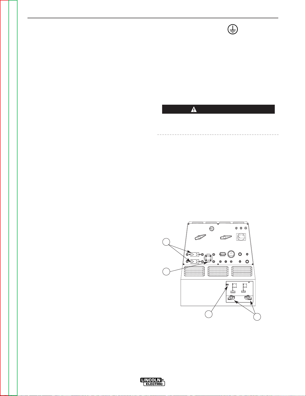
ELECTRICAL CONNECTIONS
See Figure A.1 for location of the 120 and 240 volt
receptacles, weld output terminals, circuit breakers
and ground stud.
MACHINE GROUNDING
Because the RANGER 300 creates its own power from
its diesel-engine driven generator, and if the machine
is not connected to premises wiring (home, shop, etc.),
you do not need to connect the machine frame to an
earth ground. However, for best protection against
electrical shock, connect a heavy gauge wire (#8 AWG
or larger) from the ground stud located on the bottom
of the output panel (Figure A.1) to a suitable earth
ground such as a metal pipe driven into the ground.
The ground stud is marked with the ground symbol.
Do not ground the machine to a pipe that carries
explosive or combustible material.
When the Ranger 300 is mounted on a truck or a trailer, the machine generator ground stud MUST be
securely connected to the metal frame of the vehicle.
See Figure A.1.
If the RANGER 300 is connected to premises wiring
such as a home or shop, it must be properly connected to the system earth ground.
INSTALLATION
A-6 A-6
RANGER 300 D AND 300 DLX
Return to Section TOC Return to Section TOC Return to Section TOC Return to Section TOC
Return to Master TOC Return to Master TOC Return to Master TOC Return to Master TOC
WARNING
F
E
2
1
4
3
1. 120/240 VOLT, 50 AMP RECEPTACLE
2. 120 VOLT, 15 AMP RECEPTACLES (2)
3. WELD OUTPUT TERMINALS
4. GROUND STUD
FIGURE A.1
RANGER 300 OUTPUT CONNECTIONS
Page 14

WELDING CABLE CONNECTIONS
CABLE SIZE AND LENGTH
Be sure to use welding cables that are large enough.
The correct size and length becomes especially important when you are welding at a distance from the
welder.
Table A.1 lists recommended cable sizes and lengths
for rated current and duty cycle. Length refers to the
distance from the welder to the work and back to the
welder. Cable diameters are increased for long cable
lengths to reduce voltage drops.
Lincoln Electric offers a welding accessory kit with the
properly specified welding cables. See the Accessories
section of this manual for more information.
TABLE A.1
CABLE INSTALLATION
Install the welding cables to your RANGER 300 as follows. See Figure A.1 for location of parts.
1. The diesel engine must be OFF to install welding
cables.
2. Remove the flanged nuts from the weld output terminals.
3. Connect the electrode holder and work cables to
the weld output terminals. The terminals are identified on the case front.
4. Tighten the flanged nuts securely.
5. Be certain that the metal piece you are welding (the
“work”) is properly connected to the work clamp
and cable.
6. Check and tighten the connections periodically.
• Loose connections will cause the output terminals to
overheat. The terminals may eventually melt.
• Do not cross the welding cables at the output terminal connection. Keep the cables isolated and separate from one another.
AUXILIARY POWER RECEPTACLES,
PLUGS, AND HAND-HELD EQUIPMENT
The control panel of the RANGER 300 features three
auxiliary power receptacles. See Figure A.1.
• Two 15 amp, 120 volt duplex (double outlet) recep-
tacles.
• One 50 amp 120/240 volt simplex (single outlet)
receptacle.
Through these receptacles the machine can supply up
to 12,000 rated continuous watts of single-phase, 60
Hz AC power.
For further protection against electric shock, any electrical equipment connected to the generator receptacles must use a three-blade, grounded type plug or an
Underwriter’s Laboratories (UL) approved double insulation system with a two-blade plug. Lincoln offers an
accessory plug kit that has the right type of plugs. See
the Accessories section of this manual for more information.
If you need ground fault protection for hand-held
equipment, refer to the K896-1 GFCI Receptacle kit in
the Accessories section of this manual for more information.
CIRCUIT BREAKERS
The RANGER 300 machines are equipped with 50
amp circuit breakers on the 120/240 V receptacle and
15 amp circuit breakers on the 120 V receptacles for
overload protection. Under high heat a breaker may
tend to trip at lower loads than it would normally.
INSTALLATION
A-7 A-7
RANGER 300 D AND 300 DLX
Return to Section TOC Return to Section TOC Return to Section TOC Return to Section TOC
Return to Master TOC Return to Master TOC Return to Master TOC Return to Master TOC
TOTAL COMBINED LENGTH OF
ELECTRODE AND WORK CABLES
Cable Length
0-50 Ft. (0-15 meters)
50-100 Ft. (15-30 meters)
100-150 Ft. (30-46 meters)
150-200 Ft. (46-61 meters)
200-250 Ft. (61-76 meters)
Cable Size for
300 Amps
100% Duty Cycle
1/0 AWG
1/0 AWG
2/0 AWG
2/0 AWG
3/0 AWG
CAUTION
Page 15

Return to Section TOC Return to Section TOC Return to Section TOC Return to Section TOC
Return to Master TOC Return to Master TOC Return to Master TOC Return to Master TOC
Never bypass the circuit breakers. Without overload
protection, the RANGER 300 D/DLX could overheat
and/or cause damage to the equipment being used.
PREMISES WIRING
The RANGER 300 is suitable for temporary, standby,
or emergency power using the engine manufacturer’s
recommended maintenance schedule. With its threewire grounded neutral generator, it can be permanently installed as a standby power unit for 240 volt, threewire, single phase 50 ampere service.
Only a licensed, certified, trained electrician should
install the machine to a premises or residential electrical system. Be certain that:
• The installation complies with the National Electrical
Code and all other applicable electrical codes.
• The premises is isolated and no feedbacking into
the utility system can occur. Certain state and local
laws require the premises to be isolated before the
generator is linked to the premises. Check your
state and local requirements.
• A double pole, double throw transfer switch in conjunction with the properly rated double throw circuit
breaker is connected between the generator power
and the utility meter.
The following information and the connection diagram,
Figure A.2, can be used as a guide by the electrician
for most applications to premises wiring.
1. Install a double pole, double throw switch between
the power company meter and the premises disconnect. The switch rating must be the same as
or greater than the premises disconnect and
service overcurrent protection.
2. Take the necessary steps to assure that the load is
limited to the capacity of the RANGER 300 by
installing a 50 amp 240 volt double pole circuit
breaker. Maximum rated load for the 240 volt auxiliary is 50 amperes. Loading above 50 amperes
will reduce output voltage below the allowable
– 10% of rated voltage. This may damage appliances or other motor-driven equipment.
3. Install a 50 amp 120/240 volt plug (NEMA type 14-
50) to a double pole circuit breaker using No. 8 or
larger, 4 conductor cable of the desired length.
(The 50 amp 120/240 volt plug is available in the
optional power plug kit.)
4. Plug this cable into the 50 amp 120/240 volt
receptacle on the RANGER 300 case front.
INSTALLATION
A-8 A-8
RANGER 300 D AND 300 DLX
WARNING
CAUTION
Page 16
Return to Section TOC Return to Section TOC Return to Section TOC Return to Section TOC
Return to Master TOC Return to Master TOC Return to Master TOC Return to Master TOC
INSTALLATION
A-9 A-9
RANGER 300 D AND 300 DLX
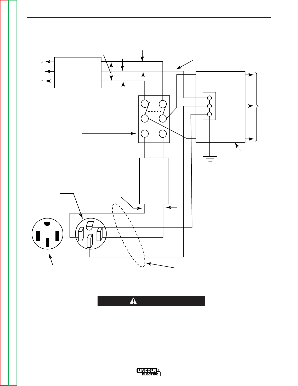
FIGURE A.2
CONNECTION OF RANGER 300 TO PREMISES WIRING
240 Volt
60 Hz.
3-Wire
Service
POWER
COMPANY
METER
240 VOLT
120 VOLT
120 VOLT
LOAD
N
NEUTRAL
BUS
GROUND
PREMISES
DISCONNECT AND
SERVICE
OVERCURRENT
PROTECTION
GND
N
NOTE: No. 6 COPPER CONDUCTOR CABLE SEE
NATIONAL ELECTRICAL CODE FOR ALTERNATE WIRE
SIZE RECOMMENDATIONS.
240 VOLT
GROUNDED CONDUCTOR
50AMP
240 VOLT
DOUBLE
POLE
CIRCUIT
BREAKER
DOUBLE POLE DOUBLE THROW
SWITCH RATING TO BE THE SAME
AS OR GREATER THAN PREMISES
SERVICE OVERCURRENT
PROTECTION.
50 AMP, 120/240
VOLT PLUG
NEMA TYPE 14-50
50 AMP, 120/240 VOLT
RECEPTACLE
Connection of Ranger 300 to premises wiring must
be done by a licensed electrician and must comply
with the National Electrical Code and all other
applicable electrical codes.
WARNING
Page 17

NOTES
RANGER 300 D AND 300 DLX
Return to Section TOC Return to Section TOC Return to Section TOC Return to Section TOC
Return to Master TOC Return to Master TOC Return to Master TOC Return to Master TOC
Page 18

Return to Master TOC Return to Master TOC Return to Master TOC Return to Master TOC
Section B-1 Section B-1
RANGER 300 D AND 300 DLX
TABLE OF CONTENTS
- OPERATION SECTION -
Operation...............................................................................................................................Section B
Safety Instructions ......................................................................................................................B-2
Additional Safety Precautions..............................................................................................B-2
General Description ....................................................................................................................B-3
Design Features .........................................................................................................................B-3
Recommended Applications ......................................................................................................B-4
Welder .................................................................................................................................B-4
Generator .............................................................................................................................B-4
Limitations...................................................................................................................................B-4
Controls and Settings.................................................................................................................B-5
Welder/Generator Controls .................................................................................................B-5
Engine Controls....................................................................................................................B-7
Engine Operation ........................................................................................................................B-9
Before Starting the Engine ...................................................................................................B-9
Starting the Engine...............................................................................................................B-9
Cold Weather Starting........................................................................................................B-10
Stopping the Engine...........................................................................................................B-10
Break-in Period ..................................................................................................................B-10
Welding Operation ....................................................................................................................B-11
General Information............................................................................................................B-11
AC/DC Stick (Constant Current) Welding ..........................................................................B-11
AC/DC TIG (Constant Current) Welding.............................................................................B-12
DC Wire Feed Welding (CV) with Ranger 300 DLX............................................................B-13
DC Wire Feed Welding (CV) with Ranger 300 D ................................................................B-14
Carbon Arc Gouging (Constant Current)............................................................................B-14
Summary of Welding Processes and Machine Settings....................................................B-15
Auxiliary Power ........................................................................................................................B-17
Simultaneous Welding and Power Loads ..........................................................................B-17
120/240 V Dual Voltage Receptacle ..................................................................................B-18
120 V Duplex Receptacles.................................................................................................B-18
Page 19
OPERATING INSTRUCTIONS
Read and understand this entire section before operating your RANGER 300.
SAFETY INSTRUCTIONS
Do not attempt to use this equipment until you have
thoroughly read all the operation and maintenance
manuals supplied with your machine. They include
important safety precautions; detailed engine starting,
operating, and maintenance instructions; and parts
lists.
ELECTRIC SHOCK can kill.
• Do not touch electrically live parts such
as output terminals or internal wiring.
• Insulate yourself from the work and
ground.
• Always wear dry insulating gloves.
FUMES AND GASES can be dangerous.
• Keep your head out of fumes.
• Use ventilation or exhaust to remove
fumes from breathing zone.
WELDING SPARKS can cause fire or
explosion.
• Keep flammable material away.
• Do not weld on containers that have held
combustibles.
ARC RAYS can burn.
• Wear eye, ear, and body protection.
ENGINE EXHAUST can kill.
• Use in open, well ventilated areas or
vent exhaust to the outside.
• Do not stack anything on or near the
engine.
MOVING PARTS can injure.
• Do not operate this equipment with
any of its doors open or guards off.
• Stop the engine before servicing it.
• Keep away from moving parts.
Only qualified personnel should install, use, or service this equipment.
ADDITIONAL SAFETY PRECAUTIONS
Always operate the welder with the hinged door
closed and the side panels in place. These provide
maximum protection from moving parts and insure
proper cooling air flow.
OPERATION
B-2 B-2
RANGER 300 D AND 300 DLX
Return to Section TOC Return to Section TOC Return to Section TOC Return to Section TOC
Return to Master TOC Return to Master TOC Return to Master TOC Return to Master TOC
WARNING
WARNING
Page 20

GENERAL DESCRIPTION
The RANGER 300 is a diesel-engine driven, multiprocess AC and DC arc welder and AC power generator for commercial and residential applications. As a
generator it can supply up to 12,000 continuous watts
of 120/240 volt, 60 Hz, single-phase AC power to
operate AC power tools, battery chargers, and lighting. It can also be used to provide standby power. As
a welder it provides 300 amps of AC current for welding with AC stick electrodes or 300 amps of DC current for DC stick welding. The RANGER 300 can also
perform AC/DC TIG welding and DC semiautomatic
wire feed welding.
The engine used on the Ranger 300 machines is the
Kubota "Super Five" water-cooled, 3 cylinder DH905
engine. The DH905 has an offset piston design with
built-in steel strut and a more rigid crankcase. The
Kubota "Three Vortex Combustion System" gives
higher power output, lower fuel consumption, lower
noise, and cleaner exhaust. The "Super Glow System"
gives rapid pre-heating for easy starting in cold weather. The large oil sump adds to the long life of this
engine. The high capacity 30 amp alternator gives fast
charging of the 495 CCA battery. The engine is
extremely smooth and has very low vibration, even at
low idle speed.
The Ranger 300 machines are housed in a heavy
gauge steel case that is protected by a durable powder paint finish. The case is completely insonorized for
remarkably quiet operation. An easy to open hinged
door allows access to the engine for single side service. The welder alternator has all copper windings
and a high temperature insulation system that includes
three coats of electrical grade varnish.
DESIGN FEATURES - ALL MODELS
FOR WELDING
• Excellent AC and DC constant current output for
stick welding applications.
• 40 to 300 amps constant current output with seven
range settings.
• Excellent semi-automatic wire feed welding on constant voltage output range(s).
• TIG welding - full range on DC and up to 250 amps
on AC.
• 100% duty cycle rating on all output ranges.
• Remote control capability standard on all models.
Amphenol receptacle for easy connection of Lincoln
remote control accessories.
FOR AUXILIARY POWER
• 12,000 watts of 120/240 volt 60Hz AC auxiliary
power.
• Power for tools, lights, electric pumps and for
standby emergency power.
• Ability to drive a 2 HP motor (provided it is started
under no load).
• Two 15 amp industrial grade 120 volt duplex receptacles for up to 60 amps of 120 volt power.
• One 50 amp 120/240 volt dual voltage receptacle
for up to 50 amps of 240 volt auxiliary power.
Allows easy connection to premises wiring.
• Four 15 amp circuit breakers for 120V duplex
receptacles and two 50 amp circuit breakers for
240V receptacle.
• Ability to weld and have AC power at the same time
(within machine total capacity).
• Compatible with GFCIs (ground fault circuit interrupters).
OTHER FEATURES
• Insonorized for extremely quiet operation [(99LW(A)
and 74 db(A) @ 23 ft (7m)].
• Kubota 3-cylinder, liquid cooled, diesel engine.
Designed for long life, easy maintenance, excellent
fuel economy and low noise.
• Engine always starts in low idle for minimum engine
wear in cold weather.
• Manual operated lift pump for easy priming of
engine if it runs out of fuel.
• Engine protection system shuts engine down on low
oil pressure or over temperature of coolant.
• Indicator lights for low oil pressure, over temperature and battery charger low output.
• Engine Hour Meter standard on all models.
• Engine coolant recovery bottle eliminates air in radiator and makes it easy to check coolant level.
• Battery with 495 cold cranking amps.
• Straight through ventilation - cooling air for welder
alternator enters front of machine and is exhausted
out rear.
• Large capacity 10 gallon (38 l) fuel tank.
• Automatic idler reduces engine speed when not
welding or drawing auxiliary power. Machine
always starts in low idle. Reduces fuel consumption
and extends engine life.
• Compact size fits many smaller trucks.
• Single side engine service with easy to open access
door.
• Copper alternator windings and high temperature
insulation for dependability and long life.
• Powder painted case and base for outstanding corrosion protection.
OPERATION
B-3 B-3
RANGER 300 D AND 300 DLX
Return to Section TOC Return to Section TOC Return to Section TOC Return to Section TOC
Return to Master TOC Return to Master TOC Return to Master TOC Return to Master TOC
Page 21

Return to Section TOC Return to Section TOC Return to Section TOC Return to Section TOC
Return to Master TOC Return to Master TOC Return to Master TOC Return to Master TOC
OPERATION
B-4 B-4
RANGER 300 D AND 300 DLX
ADDITIONAL FEATURES
RANGER 300 D (K1522-1)
• One constant voltage wire-feed welding range - 80
to 200 amps.
The wire feed setting permits the Ranger 300D to be
used with the LN-25 Wire Feeder and .035, .045 or
.068 NR®-211-MP Innershield electrodes. Limited
MIG (GMAW) welding can also be done with .030 or
.035 L-50 and L-56 using blended Argon shielding
gas. “Auto-Idle” functions when using an LN-25
with an internal contactor.
ADDITIONAL FEATURES
RANGER 300 DLX (K1522-2)
• Four constant voltage (CV) wire-feed welding
ranges with fine control on each range for welding
at 40 to 300 amps.
• Excellent arc characteristics with MIG (GMAW) and
recommended Innershield electrodes (FCAW).
• Wire feeder amphenol receptacle (14-pin) for quick
connection of control cable.
• Voltmeter for reading CV wire-feed welding arc voltage.
• Built in contactor with front panel selection of
“cold” or “hot” welding terminals.
• Aluminum TIG welding when used with K930-1 TIG
Module. Output contactor control with Amptrol.
• Recommended wire feeders are the LN-25 with 42
Volt Remote Output Control Module or with internal
contactor and all models of the LN-7.
RECOMMENDED APPLICATIONS
WELDER
The RANGER 300 provides excellent constant current
AC/DC welding output for stick (SMAW) welding and
for TIG welding, and it offers constant voltage output
for DC semiautomatic wire feed welding.
GENERATOR
The RANGER 300 gives AC generator output for medium use demands.
LIMITATIONS
• The Ranger 300 is not recommended for any
processes besides those that are normally performed using stick welding (SMAW), TIG welding
(GTAW), MIG (GMAW) welding and Innershield®
(FCAW) welding.
• The RANGER 300 D/DLX is not recommended for
pipe thawing.
• During welding, generator power is limited and output voltages can drop. Therefore, DO NOT OPER-
ATE ANY SENSITIVE ELECTRICAL EQUIPMENT
WHILE YOU ARE WELDING. See Table B.5 for
permissible simultaneous welding and auxiliary
power loads.
Page 22
Return to Section TOC Return to Section TOC Return to Section TOC Return to Section TOC
Return to Master TOC Return to Master TOC Return to Master TOC Return to Master TOC
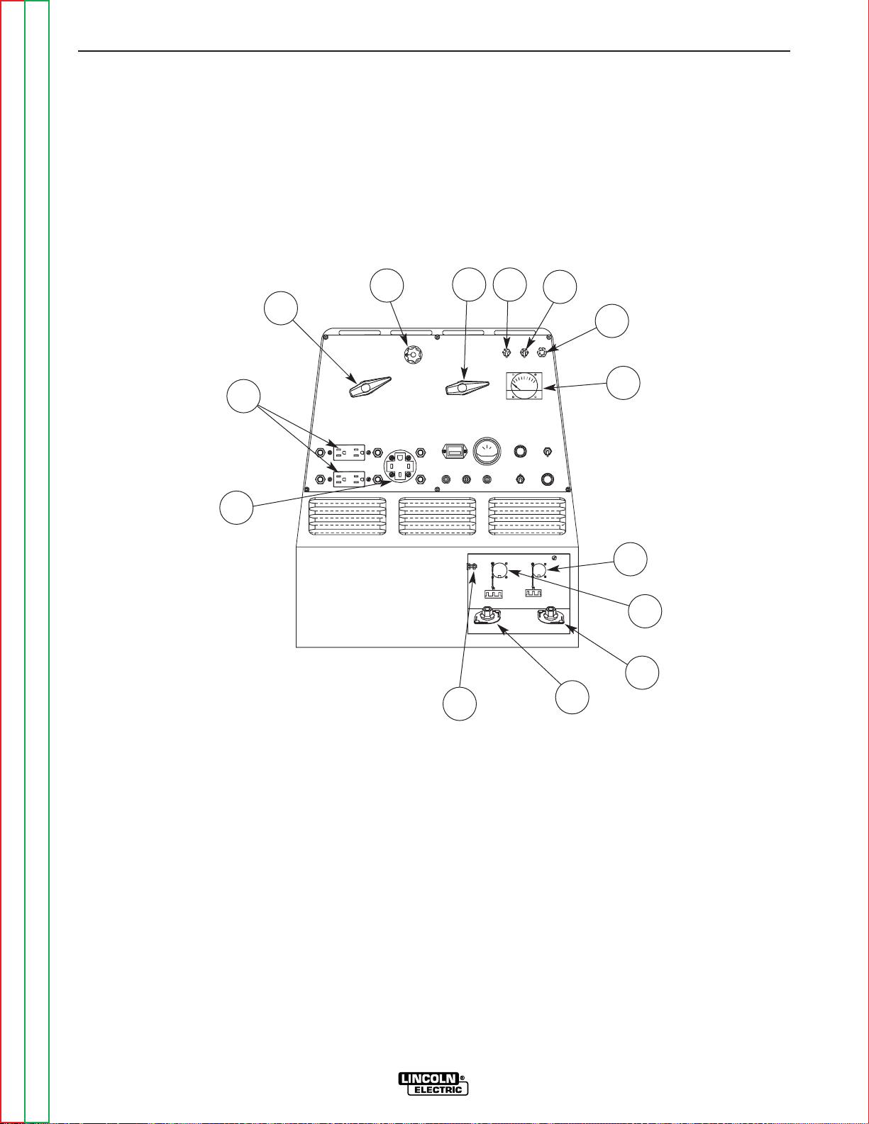
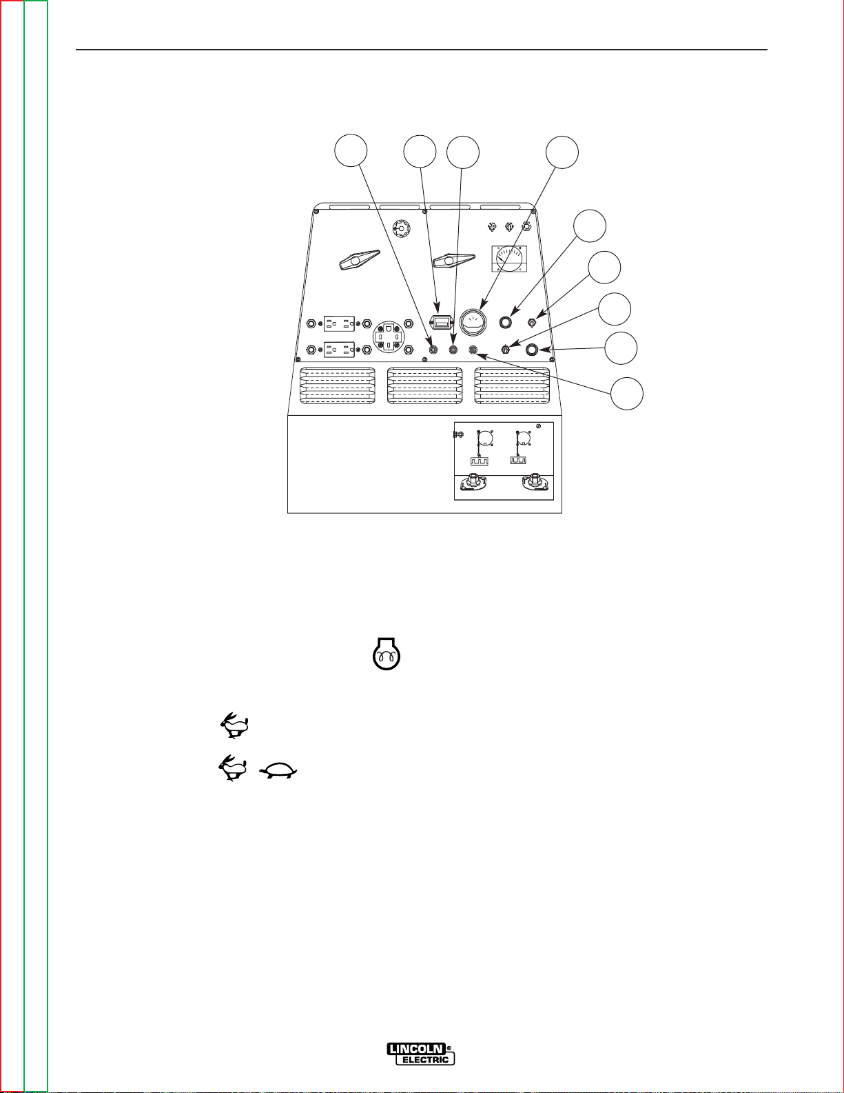
WELDER/GENERATOR CONTROLS
See Figure B.1 for the location of the following features:
1. OUTPUT RANGE SELECTOR: Selects continuous
current output for constant current stick or TIG
applications (blue settings) and constant voltage
wire feed applications (red settings). The amperages on the dial correspond to the maximum
amperages for each corresponding range setting.
Never change the range switch setting while welding, since this could damage the switch.
2. FINE OUTPUT CONTROL: Allows fine adjustment
of current or voltage within the selected output
range.
3. POLARITY SWITCH: Selects DC+, DC- or AC
welding output. Color codings aid in the proper
selection of stick (blue) or wire feed (red) polarity
setting. On the RANGER 300 DLX the color setting
of the polarity switch must match the color setting
of the OUTPUT RANGE SELECTOR. Never
change the polarity switch setting while welding
since this could damage the switch.
4. CONTROL AT WELDER/REMOTE CONTROL
SWITCH: Allows the operator to control welding
output at the welding control panel or at a remote
station. Remote connections are made at the 6 pin
or 14 pin amphenol connector.
OPERATION
B-5 B-5
RANGER 300 D AND 300 DLX
F
E
FIGURE B.1
OUTPUT PANEL CONTROLS
8
2
1
7
3 4
5
6
14
12
13
10
9
11
CONTROLS AND SETTINGS
All generator/welder controls are located on the
Output Control Panel of the machine case front.
Diesel engine glow plug, idler control, and start/stop
controls are also on the case front. See Figure B.1 and
the explanations that follow.
Page 23

5. WELDING TERMINALS SWITCH (DLX Model Only)
The toggle switch labeled “WELDING TERMINALS
ALWAYS ON” and “WELDING TERMINALS
REMOTELY CONTROLLED” is used to control the
operation of the RANGER 300 DLX output contactor. With the switch in the “WELDING TERMINALS
ALWAYS ON” position, the contactor is closed at
low and high idle.
When a wire feeder or TIG Module control cable is
attached to either the 6-pin or 14-pin amphenol
connector and the Welding Terminals switch is in
the “WELDING TERMINALS REMOTELY CONTROLLED” position, the contactor is open in low
idle and high idle until and the wire feeder trigger or
Amptrol is closed. This closes the 2-4 circuit.
When the gun trigger or Amptrol is released, the
contactor opens and there is no voltage present at
the electrode (300 DLX only).
6. WIRE FEEDER POWER CIRCUIT BREAKER:
Opens the wire feeder circuit and disables the
feeder if a fault is detected in the circuit (300 DLX
only).
7. 15 AMP, 120 VOLT DUPLEX RECEPTACLES:
Connection point for supplying 120 volt power to
operate one or two electrical devices.
8. 50 AMP, 120/240 VOLT RECEPTACLE: Connection
point for supplying 240 volt power to operate one
electrical device.
9. WELD OUTPUT TERMINAL (TO WORK) WITH
FLANGE NUT: Provides the connection point for
the work cable.
10. WELD OUTPUT TERMINAL (TO ELECTRODE
HOLDER) WITH FLANGE NUT: Provides the connection point for the electrode holder.
11. GROUND STUD: Provides a connection point for
connecting the machine case to earth ground for
the safest grounding procedure.
12. 6-PIN AMPHENOL: For attaching optional remote
control equipment to the RANGER 300 D/DLX
(Includes contactor closure circuit on the Ranger
300 DLX and remote control circuit).
13. 14-PIN AMPHENOL (DLX Model Only): For
attaching wire feeder control cables to the
RANGER 300 DLX (Includes contractor closure
circuit, remote control circuit, wire feeder 115/42
volt power source).
14. VOLTMETER (DLX MODEL ONLY): Displays actual voltage at the output terminals when welding in
CV-mode.
OPERATION
B-6 B-6
RANGER 300 D AND 300 DLX
Return to Section TOC Return to Section TOC Return to Section TOC Return to Section TOC
Return to Master TOC Return to Master TOC Return to Master TOC Return to Master TOC
Page 24
Return to Section TOC Return to Section TOC Return to Section TOC Return to Section TOC
Return to Master TOC Return to Master TOC Return to Master TOC Return to Master TOC
OPERATION
B-7 B-7
RANGER 300 D AND 300 DLX
FIGURE B.2
ENGINE CONTROLS
ENGINE CONTROLS
See Figure B.2 for the location of the following features:
1. GLOW PLUG PUSH-BUTTON: Activates
glow plugs to preheat engine for starting.
2. IDLER CONTROL SWITCH: The idler switch has
two positions, “HIGH” and “AUTO”.
When in “HIGH” ( ) position, the engine will
run continuously at high speed.
When in “AUTO” ( / ) idle position, the
idler operates as follows:
a) Welding
Low idle with Ranger 300 DLX in the “WELDING
TERMINALS ALWAYS ON” mode or with a Ranger
300D - When the electrode touches work, the
welding arc is initiated and the engine accelerates
to full speed.
Low idle and in the “WELDING TERMINALS
REMOTELY CONTROLLED” mode - Pressing the
gun trigger or Amptrol closes the Ranger 300 DLX
output contactor and causes the engine to accelerate to full speed.
After the gun trigger or Amptrol is released and/or
welding ceases (and no auxiliary power is being
drawn), the engine will return to low idle after
approximately 10 to 14 seconds.
b) Auxiliary Power
With the engine running at low idle and auxiliary
power for lights or tools drawing approximately
100-150 watts or greater from the receptacles, the
engine will accelerate to high speed. If no power is
being drawn from the receptacles (and not welding)
for 10-14 seconds, the engine returns to low idle.
F
E
5
4
6
9
1
8
2
3
7
Page 25

3. START PUSHBUTTON: When the pushbutton is held, the starter motor cranks over
the engine - release the button once the
engine starts.
NOTE: If you press the START pushbutton when the
engine is running, you may damage the ring gear or
starter motor.
4. ENGINE HOUR METER: Records engine running
time. Use to determine when to perform required
maintenance.
5. BATTERY LIGHT: Is off when battery charging system is functioning normally. If the red light turns on
while the engine is running, the fan belt may be
broken or the alternator or the voltage regulator
may be defective.
It is normal for the light to go on when the “Engine”
switch is switched to the “ON” position with the
engine not running. It will go off after one minute
to prevent discharging the battery if the engine is
not started. If this happens, the engine protection
circuit must be reset by turning the “Engine” switch
to the “OFF” position and back to the “ON” position.
6. OIL PRESSURE LIGHT: Remains off
with proper oil pressure. If the red light
turns on while the engine is running, the engine
protection system will stop the engine.
It is normal for the light to go on when the “Engine”
switch is switched to the “ON” position with the
engine not running. It will go off after one minute
to prevent discharging the battery if the engine is
not started. If this happens, the engine protection
circuit must be reset by turning the “Engine” switch
to the “OFF” position and back to the “ON” position.
7. WATER TEMPERATURE LIGHT: Remains
off under normal operating temperatures.
If the red light turns on, the engine protection system will stop the engine. The light will
remain on when the engine is over temperature and
the “Engine” switch is in the “ON” position (engine
not running) but will go off as the engine cools.
8. FUEL LEVEL GAUGE: Displays the level of diesel
fuel in the 10-gallon fuel tank.
9. ENGINE ON-OFF SWITCH: Energizes the fuel solenoid in the “ON” position. In the STOP position,
stops fuel flow to the injection pump and stops the
engine.
OPERATION
B-8 B-8
RANGER 300 D AND 300 DLX
Return to Section TOC Return to Section TOC Return to Section TOC Return to Section TOC
Return to Master TOC Return to Master TOC Return to Master TOC Return to Master TOC
Page 26
ENGINE OPERATION
DO NOT RUN THE ENGINE AT EXCESSIVE SPEEDS.
The maximum allowable high idle speed for the
RANGER 300 is 3700 RPM, no load. Do NOT adjust
the governor screw on the engine. Severe personal
injury and damage to the machine can result if it is
operated at speeds above the maximum rated speed.
Read and understand all safety instructions included in
the Kubota instruction manual that is shipped with your
RANGER 300.
BEFORE STARTING THE ENGINE
Check the engine oil level:
See Figure D.1 for location of dipstick.
1. Be sure the machine is on a level surface.
2. Remove the engine oil dipstick and wipe it with a
clean cloth. Reinsert the dipstick and check the
level on the dipstick.
3. Add oil (if necessary) to bring the level up to the full
mark. Do not overfill.
4. Replace the dipstick.
Check and fill the engine fuel tank:
DIESEL fuel can cause fire or
explosion.
• Stop engine when fueling.
• Do not smoke when fueling.
• Do not overfill tank.
• Keep sparks and flame away from tank.
1. Remove the fuel tank cap.
2. Fill the tank approximately 4 inches (100 mm) from
the top of the filler neck to allow for fuel expansion
(observe the fuel gauge.) DO NOT FILL THE TANK
TO THE POINT OF OVERFLOW.
3. Replace the fuel tank cap and tighten securely.
NOTE: DO NOT allow the RANGER 300 to run out of
fuel. If it does, you will have to bleed the injection system. See the Maintenance section of this manual and
the Engine Operator’s Manual for instructions on
bleeding the fuel injection system.
USE DIESEL FUEL ONLY
Purchase diesel fuel in quantities that will be used
within 30 days, to assure freshness.
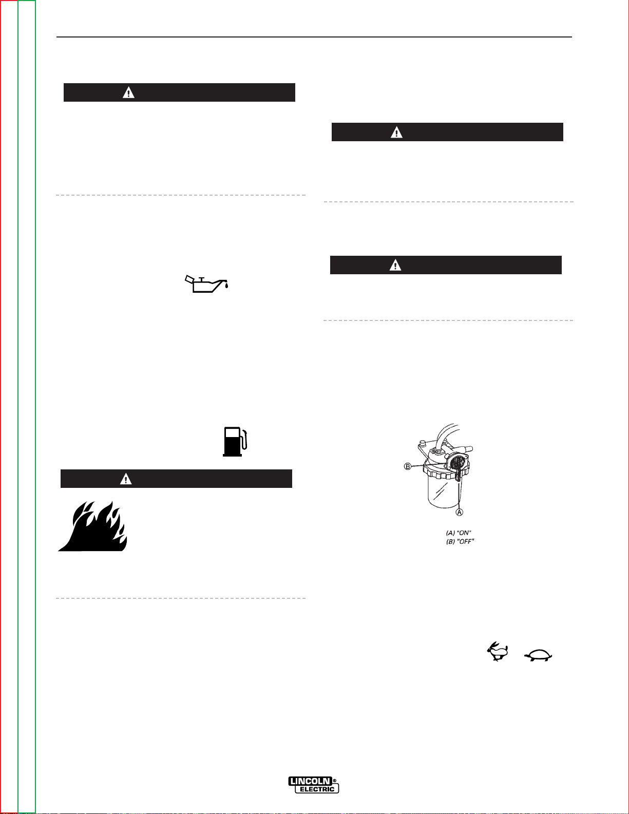
STARTING THE ENGINE
Remove all loads connected to the AC power receptacles and the welder before starting the diesel engine.
1. Open the engine compartment door and check that
the fuel shutoff valve located above the clear plastic fuel filter housing is in the open position (lever in
the vertical position). See Figure B.3.
FIGURE B.3
2. Check for proper level of coolant in the plastic
reserve overflow tank. The level should be
between the full and the low marks.
3. Check for proper oil level on the oil dipstick. Close
engine compartment door.
4. Set “IDLER” switch to “AUTO”. /
5. Set the “ENGINE” switch to “ON”. Observe that
both the oil pressure light and battery charger light
are on. Check the fuel gauge to make sure that
there is an adequate fuel level. (NEVER ALLOW
THE RANGER 300 D/DLX TO RUN OUT OF FUEL.)
OPERATION
B-9 B-9
RANGER 300 D AND 300 DLX
Return to Section TOC Return to Section TOC Return to Section TOC Return to Section TOC
Return to Master TOC Return to Master TOC Return to Master TOC Return to Master TOC
WARNING
CAUTION
CAUTION
WARNING
Page 27
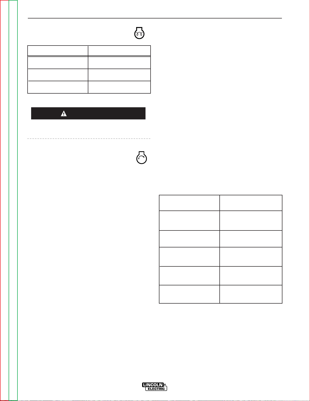
6. Press the “GLOW PLUG” button to preheat the cylinders per the following table:
Never press the Glow Plug button continuously for
more than 20 seconds.
7. Release the “GLOW PLUG” button and
press the “START” button to crank the
engine. Release when the engine starts.
8. Check that the indicator lights are off. If not, immediately stop the engine and investigate the indicated problem.
9. Allow the engine to warm up at low idle speed for
several minutes before applying a load and/or
switching to high idle. Allow a longer warm up time
in cold weather.
NOTE: If the engine fails to start in 60 seconds or
stops running, the “ENGINE” switch must be
switched to “OFF” and then switched back to “ON”
before attempting to restart the engine. This resets
the engine protection circuit.
COLD WEATHER STARTING AND
OPERATION
The Kubota engine used in the Ranger 300 can be
started in temperatures as low as 5°F (-15°C). At temperatures below 23°F (-5°C), it is recommended that
No. 1D diesel fuel be used in place of No. 2D. Allow
engine to warm up before applying a load or switching
to HIGH idle.
STOPPING THE ENGINE
1. Remove all welding and generator power loads and
let the engine cool by running it for several minutes
at low idle.
2. Stop the engine by placing the Engine Switch in the
“OFF” position. This turns off the fuel solenoid.
You can also stop the engine by turning off the fuel
valve located on the fuel filter housing.
BREAK-IN PERIOD
Any engine will use a small amount of oil during its
“break-in” period. For the diesel engine on the
RANGER 300, break-in is about 50 running hours.
Check the oil every four hours during break-in.
Change the oil after the first 50 hours of operation,
every 100 hours thereafter. Change the oil filter at the
second oil change.
During break-in, subject the RANGER 300 to moderate
loads. Avoid long periods running at idle. Before
stopping the engine, remove all loads and allow the
engine to cool several minutes.
TABLE B.1
TYPICAL RANGER 300 FUEL CONSUMPTION
* DLX model only
OPERATION
B-10 B-10
RANGER 300 D AND 300 DLX
Return to Section TOC Return to Section TOC Return to Section TOC Return to Section TOC
Return to Master TOC Return to Master TOC Return to Master TOC Return to Master TOC
Ambient Temperature
Above 50°F (10°C)
50°F (10°C) to 23°F(-5°C)
Below 23°F (-5°C)
Pre-Heat Time
NOT REQUIRED
Approximately 5 seconds
Approximately 10 seconds
CAUTION
Low Idle - No Load
2000 RPM
High Idle - No Load
3700 RPM
AC CC Weld Output
300 Amps @ 25 Volts
DC CC Weld Output
300 Amps @ 25 Volts
DC CV Weld Output
300 Amps @ 28 Volts*
Auxiliary Power
12,000 kVA
.30 gallons/hour
(1.0 liters/hour)
.60 gallons/hour
(2.2 liters/hour)
1.1 gallons/hour
(4.2 liters/hour)
1.2 gallons/hour
(4.6 liters/hour)
.90 gallons/hour
(3.6 liters/hour)
1.3 gallons/hour
(4.9 liters/hour)
Page 28

WELDING OPERATION
Do not attempt to use this equipment until you have
thoroughly read the engine manufacturer’s manual
supplied with your welder. It includes important safety precautions, detailed engine starting, operating and
maintenance instructions, and parts lists.
ELECTRIC SHOCK can kill.
• Do not touch electrically live parts or
electrode with skin or wet clothing.
• Insulate yourself from work and ground
• Always wear dry insulating gloves.
FUMES AND GASES can be dangerous.
• Keep your head out of fumes.
• Use ventilation or exhaust to remove
fumes from breathing zone.
MOVING PARTS can injure.
• Do not operate with doors open or
guards off.
• Stop engine before servicing.
• Keep away from moving parts.
WELDING SPARKS can cause fire or
explosion.
• Keep flammable material away.
ARC RAYS can burn.
• Wear eye, ear and body protection.
See additional warning information throughout this
operator’s manual.
GENERAL INFORMATION
The RANGER 300 machines can deliver from 45 to 300
amps of constant current for AC/DC stick welding.
The Ranger 300 DLX can deliver 45 to 300 amps of
constant voltage current for DC semiautomatic wire
feed welding. The Ranger 300 D can deliver 45 to 200
amps of constant voltage current for DC semiautomatic wire feed welding. AC/DC constant current TIG
welding is possible across the entire range from 45 to
300 amps, although 250 amps is the maximum recommended for AC TIG welding of aluminum.
Output can be adjusted by setting the POLARITY
SWITCH, the OUTPUT RANGE dial, and the FINE
CONTROL dial on the output control panel to the settings that are best for your selected welding process.
AC/DC STICK (CONSTANT CURRENT)
WELDING
1. Remove the flange nuts from output terminals and
place the work and electrode welding cables over
the terminals. See Figure B.4. Replace and tighten the flange nuts securely. Be sure the connections are tight.
2. Select the appropriate electrode. See “Welding
Tips 1” included with your RANGER 300.
3. Attach the work clamp securely to the work you are
welding.
4. Insert the electrode into the electrode holder.
5. Set the IDLER CONTROL to AUTO and start the
diesel engine.
6. Set the RANGE switch to a setting equal to or
slightly lower than the welding current recommended for the electrode being used. For the best
welding performance, always set the RANGE
switch to the lowest CC-blue setting that will give
the desired weld current. This will assure that the
OUTPUT dial is set towards the high end of the
dial. If the OUTPUT dial is set at 10 and the welding current is set to low, move the RANGE switch
to the next highest setting.
7. Set the POLARITY switch to the desired polarity
(CC-blue setting).
8. Set the OUTPUT control. For stick welding, always
use a setting between 5 and 10 on the dial (blue
range).
9. Strike an arc and begin welding. The OUTPUT
control can be adjusted while welding.
OPERATION
B-11 B-11
RANGER 300 D AND 300 DLX
Return to Section TOC Return to Section TOC Return to Section TOC Return to Section TOC
Return to Master TOC Return to Master TOC Return to Master TOC Return to Master TOC
CAUTION
Page 29
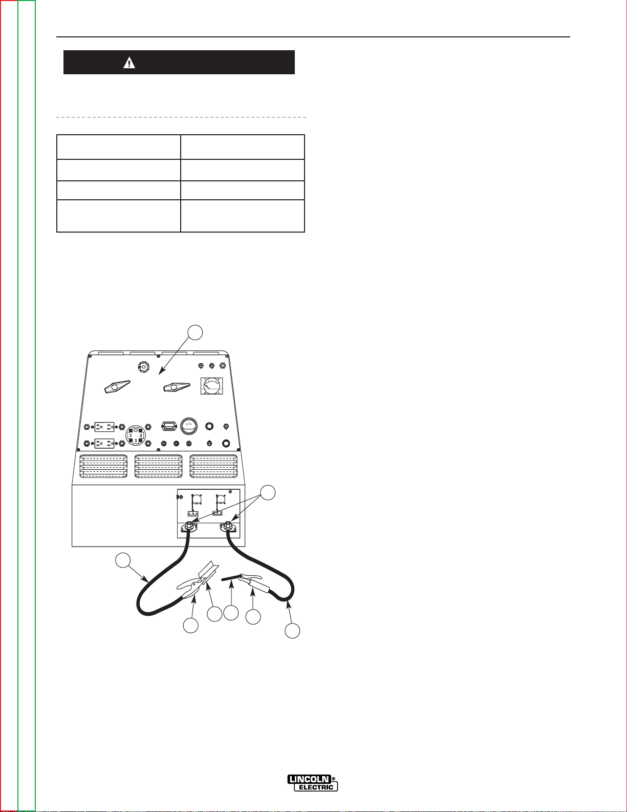
DO NOT change the RANGE switch setting while
welding. This can result in damage to the switch.
FIGURE B.4
WELDING CIRCUIT CONNECTIONS
AFTER YOU FINISH WELDING:
1. Stop the engine.
2. Allow the electrode and work to cool completely.
3. Remove the work clamp from the work.
4. Remove any remaining piece of electrode from the
electrode holder.
5. If you are finished using the RANGER 300 for welding, disconnect the welding cables from the weld
output terminals. Reattach the flange nuts and
leave them on the terminals.
AC/DC TIG (CONSTANT CURRENT)
WELDING
1. Connect the K930-1 TIG Module to the RANGER
300. Follow the installation instructions provided
with the kit.
2. Refer to the instruction manual with the TIG module (IM-528) for operation with a RANGER 300 and
proper machine settings.
3. Set the RANGE switch to the appropriate setting
for the electrode you are using. Refer to IM-528
with the TIG module or refer to Table B.2 for AC
TIG welding.
4. Set the POLARITY SWITCH to the desired polarity.
5. Do not AC TIG weld on the 300 AC range setting.
The output current may exceed the rating of the
RANGER 300.
6. Start the arc and begin welding.
NOTE: When using the RANGER 300 for AC TIG welding of aluminum, the TIG Module is to be set for CONTINUOUS HF.
AFTER YOU FINISH WELDING:
1. Stop the engine.
2. Allow the electrode and work to cool completely.
3. Remove the work clamp from the work.
OPERATION
B-12 B-12
RANGER 300 D AND 300 DLX
Return to Section TOC Return to Section TOC Return to Section TOC Return to Section TOC
Return to Master TOC Return to Master TOC Return to Master TOC Return to Master TOC
RANGE SETTING
ON MACHINE
ACTUAL
CURRENT RANGE
50
75
100
140
180
225
300
30 to 50 AMPS
50 to 75 AMPS
70 to 100 AMPS
95 to 140 AMPS
110 to 180 AMPS
130 to 225 AMPS
160 to 300 AMPS
F
E
CAUTION
1
5
8
7
6
4
3
2
1. OUTPUT CONTROL PANEL
2. ELECTRODE CABLE
3. ELECTRODE HOLDER
4. ELECTRODE
5. OUTPUT TERMINALS
6. WORK
7. WORK CLAMP
8. WORK CABLE
Page 30

Return to Section TOC Return to Section TOC Return to Section TOC Return to Section TOC
Return to Master TOC Return to Master TOC Return to Master TOC Return to Master TOC
OPERATION
B-13 B-13
RANGER 300 D AND 300 DLX
TABLE B.2
AC TIG WELDING – TIG ELECTRODE/RANGE SETTINGS
Pure (EWP) “Range” Appropriate
Tungsten Diameter Switch Settings Welding Current
1/8” 75, 100 or 140
(1)
100 - 200 amps
3/32” 50, 75 or 100 50 - 100 amps
1/16” 50, 75 or 100 45 - 150 amps
1% Thoriated “Range” Appropriate
Tungsten Diameter Switch Settings Welding Current
1/8” 100, 140 or 180 160 - 250 amps
3/32” 50, 100 or 140 100 - 180 amps
1/16” 50 or 100 60 - 120 amps
(1)
The welding current will be approximately 200 amps with the range switch set at 120 and the OUTPUT CONTROL set at 10. Do not use a range setting higher than 120 for AC TIG welding.
DC WIRE FEED WELDING (CV) WITH
RANGER 300 DLX
1. Connect one of the following: the LN-25, LN-7 or
LN-8 Wire Feeder.
2. Some recommended Innershield electrodes are:
.068 NR-211MP, .068 NR-232, NR-203 series, 5/64
NR-311, and 5/64 NS-3M. Lincore® 33 and 55
hardfacing electrodes can also be used. Cable
length and other conditions can affect the ultimate
results of this application. Request Lincoln publication N-675 for additional information.
Recommended Outershield electrodes are .045
(1.1 mm), .052 (1.3 mm), and 1/16 (1.6 mm)
Outershield 71 and 1/16 (1.6 mm) Outershield 70.
Request Lincoln publication GS-200 for additional
information.
For MIG welding, the recommended electrodes are
.030 (0.8 mm), .035 (0.9 mm) and .045 (1.1 mm) L50 and L-56. You must use a blended shielding
gas such as C25 (75% Argon, 25% CO
2
). Request
Lincoln publication GS-100 for additional information.
3. Set the IDLER CONTROL to “AUTO” for the LN-25
or “HIGH” for the LN-7 or LN-8 and start the diesel
engine.
4. Set the RANGE switch to either HIGH, MEDIUM
HIGH, MEDIUM LOW, or LOW (CV-red) depending
on your wire size and speed.
5. Set the POLARITY SWITCH to either WIRE WELDING DC+ or WIRE WELDING DC- depending on
the electrode.
6. Set the OUTPUT control to a setting between 1 and
10 that gives the most stable arc for the application. Try a higher RANGE switch setting if the arc
is unstable.
7. Strike an arc and begin welding. The OUTPUT
control can be adjusted while welding. DO NOT
change the RANGE switch setting while welding.
This can result in damage to the switch.
AFTER YOU FINISH WELDING:
1. Stop the engine.
2. Allow the work to cool completely.
3. Remove the work clamp from the work.
Page 31

DC WIRE FEED WELDING (CV) WITH
RANGER 300 D
1. Connect an LN-25 with internal contactor to the
Ranger 300 D.
2. The only Innershield electrode recommended for
use with the Ranger 300 D is NR211MP. The electrode sizes and welding ranges that can be used
with the Ranger 300 D are shown in the following
table:
The Ranger 300 D is recommended for limited "MIG"
welding (GMAW - gas metal arc welding). The recommended electrodes are .030 and .035 L-50 and L-56.
They must be used with a blended shielding gas such
as C25 (75% Argon - 25% CO
2
). The .035 diameter
electrode gives improved starting compared to .030
diameter. The welding ranges that can be used with
the Ranger 300 D are shown in the following table:
3. Set the IDLER control to AUTO.
4. Set the RANGE switch to WIRE FEED (CV-red setting).
5. Set the POLARITY SWITCH to either WIRE WELDING DC+ (red) or WIRE WELDING DC- (red),
depending on the electrode.
6. Set the OUTPUT control to a setting between 1 and
10 that gives the most stable arc for the application.
7. Strike an arc and begin welding. The OUTPUT
control can be adjusted while welding. DO NOT
change the RANGE switch setting while welding.
This can result in damage to the switch.
AFTER YOU FINISH WELDING:
1. Stop the engine.
2. Allow the work to cool completely.
3. Remove the work clamp from the work.
CARBON ARC GOUGING
(CONSTANT CURRENT)
1. The recommended electrode is a 3/16” (4.8 mm)
dia. carbon.
2 Set the RANGE switch to 300.
3 Set the POLARITY switch to DC+ (cc - blue setting).
4 Set the OUTPUT control to 10.
5. Strike an arc and begin gouging.
AFTER YOU FINISH GOUGING:
1. Stop the engine.
2. Allow the electrode and work to cool completely.
3. Remove the work clamp from the work.
OPERATION
B-14 B-14
RANGER 300 D AND 300 DLX
Return to Section TOC Return to Section TOC Return to Section TOC Return to Section TOC
Return to Master TOC Return to Master TOC Return to Master TOC Return to Master TOC
Electrode
Diameter
Wire Speed
in. / min.
Approximate
Current Range
.035”
.045”
.068”
70 - 110
70 - 130
40 - 90
60 - 120 amps
120 - 170 amps
125 - 210 amps
Electrode
Diameter
Wire Speed
in. / min.
Approximate
Current Range
.030”
.035”
150 - 450
100 - 350
80 - 170 amps
80 - 190 amps
Page 32

OPERATION
B-15 B-15
RANGER 300 D AND 300 DLX
Return to Section TOC Return to Section TOC Return to Section TOC Return to Section TOC
Return to Master TOC Return to Master TOC Return to Master TOC Return to Master TOC
SUMMARY OF WELDING PROCESSES AND MACHINE SETTINGS
TABLE B.3
SUMMARY OF WELDING PROCESSES FOR RANGER 300 DLX
CONTROL
CABLE &
DIAGRAM
IDLE
MODE
OUTPUT
CONTROL
SWITCH
WELDING
TERMINALS
SWITCH
ELECTRODE
WHEN NOT
WELDING
TO START WELDING
PROCESS
STICK - CC
CARBON ARC
GOUGING - CC
TIG - CC
K930-1 TIG MODULE /
K936-1 CONTROL
CABLE
WIRE FEED - CV,
LN-25 WITH 42V REMOTE CONTROL KIT
WIRE FEED - CV,
LN-25 WITH
INTERNAL
CONTACTOR
WIRE FEED - CV,
LN-742
WIRE FEED - CV,
LN-7 or LN-8
K487-15 WIRE FEEDCV SPOOL GUN / K488
CONTROL MODULE
Touch electrode to work.
Welding starts immediately
and engine goes to high idle.
Press Amptrol. Welding
starts immediately.
Press gun trigger, Ranger
300 DLX contactor closes.
Welding starts immediately
and engine goes to high idle.
Press gun trigger, LN-25
contactor closes. Welding
starts immediately and
engine goes to high idle.
Press gun trigger, Ranger
300 DLX contactor closes.
Welding starts immediately
and engine goes to high idle.
Press gun trigger, Ranger
300 DLX contactor closes.
Welding starts immediately.
Press gun trigger, Ranger
300 DLX contactor closes.
Welding starts immediately.
NO
YES
S23732-9
YES
S23732-3
NO
S23732-1
S23732-2
YES
S23732-5
YES
S23732-4
S23732-6
YES
S23732-8
AUTO
AUTO
AUTO
AUTO
AUTO
HIGH
HIGH
AT
WELDER
REMOTE
REMOTE
AT
WELDER
REMOTE
REMOTE
AT
WELDER
ALWAYS
ON
REMOTE
REMOTE
ALWAYS
ON
REMOTE
REMOTE
REMOTE
HOT
COLD
COLD
COLD
COLD
COLD
COLD
Page 33

INSTALLATION
B-16 B-16
RANGER 300 D AND 300 DLX
Return to Section TOC Return to Section TOC Return to Section TOC Return to Section TOC
Return to Master TOC Return to Master TOC Return to Master TOC Return to Master TOC
CONTROL
CABLE &
DIAGRAM
IDLE
MODE
OUTPUT
CONTROL
SWITCH
ELECTRODE
WHEN NOT
WELDING
TO START WELDING
PROCESS
STICK - CC
CARBON ARC
GOUGING - CC
TIG - CC
K930-1 TIG MODULE /
K936-1 CONTROL CABLE
WIRE FEED - CV,
LN-25 /
INTERNAL
CONTACTOR
WIRE FEED - CV,
LN-7 / K240
CONTACTOR KIT
Touch electrode to work.
Welding starts immediately
and engine goes to high idle.
Press Amptrol. Welding
starts immediately.
Press gun trigger, LN-25
contactor closes. Electrode
touches work, welding starts
immediately and engine goes
to high idle.
Press gun trigger, K240
contactor closes. Welding
starts immediately.
NO
YES
S23732-10
NO
S23732-1
S23732-2
YES
S23732-11
AUTO
AUTO
AUTO
HIGH
AT
WELDER
REMOTE
AT
WELDER
AT
WELDER
HOT
HOT
COLD
COLD
SUMMARY OF WELDING PROCESSES AND MACHINE SETTINGS, continued
TABLE B.4
SUMMARY OF WELDING PROCESSES FOR RANGER 300 D
Page 34

AUXILIARY POWER
The Ranger 300 can provide up to 12,000 watts of
120/240 volts AC, single-phase 60 HZ power for continuous use. The front of the machine includes three
receptacles for connecting AC power plugs, one 50
amp 120/240 V NEMA 14-50R receptacle and two 15
amp 120 V NEMA 5-15R receptacles. Do not connect
any plugs that connect to the power receptacles in
parallel.
Start the engine and set the “IDLER” control switch to
the desired operating mode. Set the “CONTROL” to
10. Voltage is now correct at the receptacles for auxiliary power.
Most single-phase motors through 2.0 HP can be
started if there is no load on the motor or other load
connected to the machine. Since the full load current
of a 2.0 HP motor is typically 18 to 20 amps when
operated at 120 V or 9 to 11 amps when operated at
240 V, it should be connected to the 120/240 dual voltage receptacle. The full load current of a 1.5 HP motor
is typically 15 to 17 amps when operated at 120 V or
7.5 to 8.5 amps when operated at 240 V. It also should
be connected to the 120/240 dual voltage receptacle.
A 1.0 HP motor that draws less than 15 amps at 120 V
can be plugged into one of the 120 V duplex receptacles.
SIMULTANEOUS WELDING AND
POWER LOADS
Auxiliary power ratings are with no welding load.
Simultaneous welding and power loads are permitted
by the following table. The permissible currents shown
assume that current is being drawn from either the
120 V or 240 V supply (not both at the same time).
OPERATION
B-17 B-17
RANGER 300 D AND 300 DLX
Return to Section TOC Return to Section TOC Return to Section TOC Return to Section TOC
Return to Master TOC Return to Master TOC Return to Master TOC Return to Master TOC
Output
Selector
Setting
Welding
Output
Amps
Permissible
Power Watts
(Unity Power
Permissible
Auxiliary Current in
Amperes @ 120V
Permissible
Auxiliary Current in
Amperes @ 240V
0
13
20
27
33
38
42
17
40
13
27
8
33
0
25
0
25
40
53
60
60
60
33
60
25
60
17
60
0
50
NONE
3000
4800
6400
8000
9000
10,000
4000
9600
3000
8800
2000
8000
0
6000
300
225
180
140
100
75
50
200
60
225
80
250
100
300
150
300
225
180
140
100
75
50
CV LOW (300 DLX)
CV (300 D)
CV MED. LOW
(300 DLX)
CV MED. HIGH
(300 DLX)
CV HIGH
(300 DLX)
TABLE B.5
RANGER 300 SIMULTANEOUS WELDING AND POWER LOADS
(OUTPUT CONTROL SET AT 10)
NOTE: Voltage and permissible watts decrease as “CONTROL” is adjusted to settings less than 10. It is recommended
that at settings less than 10, only incandescent lighting loads be connected to the auxiliary power receptacles.
Page 35
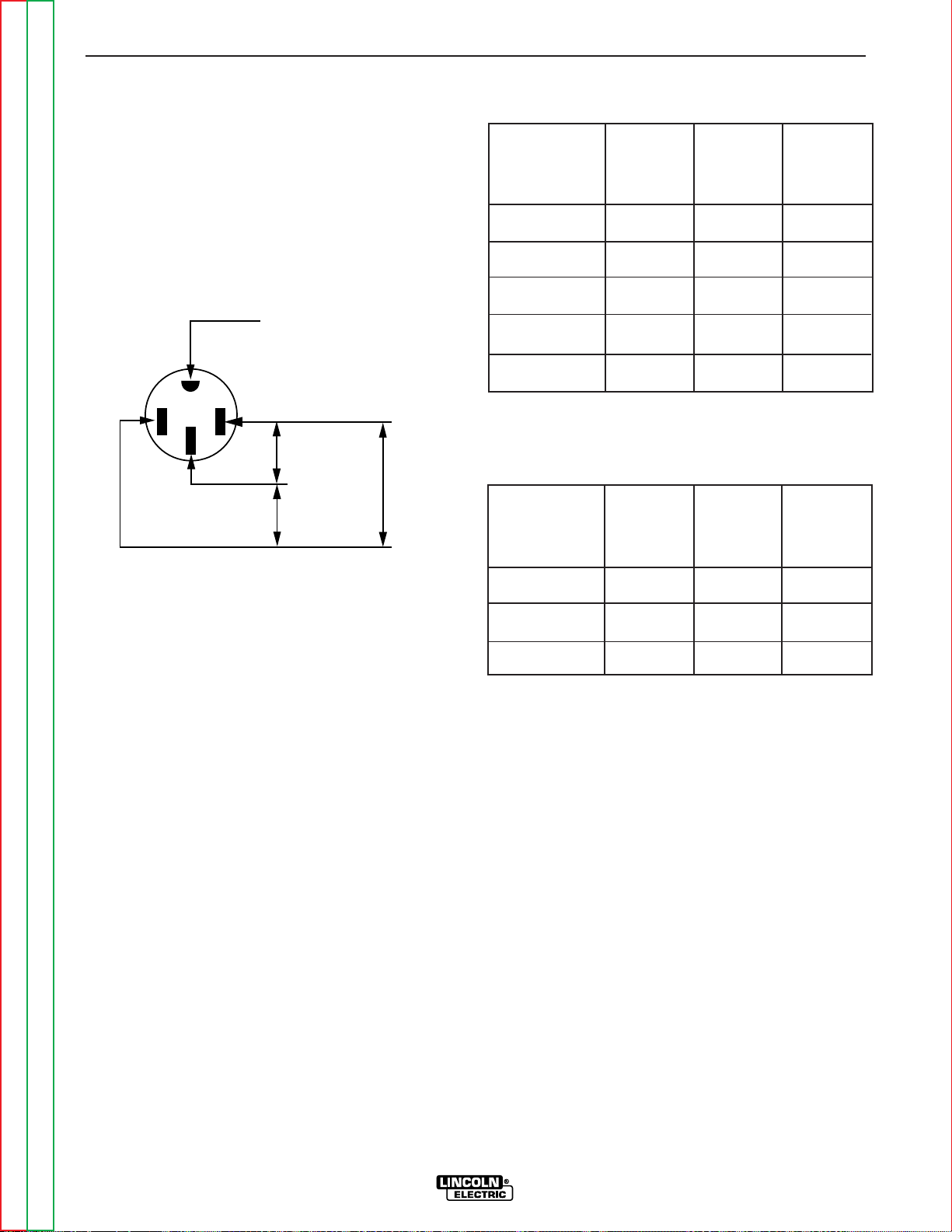
Return to Section TOC Return to Section TOC Return to Section TOC Return to Section TOC
Return to Master TOC Return to Master TOC Return to Master TOC Return to Master TOC
OPERATION
B-18 B-18
RANGER 300 D AND 300 DLX
120/240 V DUAL VOLTAGE RECEPTACLE
The 120/240 V receptacle can supply up to 50 amps
of 240 V power to a two wire circuit, up to 50 amps of
120 V power from each side of the three wire circuit,
(up to 100 amps total). Do not connect the 115 V circuits in parallel. Current sensing for the automatic idle
feature is in both legs of the three wire circuit as shown
below.
FIGURE B.5
120 V DUPLEX RECEPTACLES
The 120 V auxiliary power receptacles should only be
used with three wire grounding type plugs or approved
double insulated tools with two wire plugs.
MAXIMUM CURRENT DRAW FROM
120 V DUPLEX RECEPTACLES - NO WELDING
EACH HALF OF
EACH 120 V
DUPLEX
TOTAL FROM
ONE 120 V
DUPLEX
TOTAL FROM
BOTH 120 V
DUPLEXES
240 V LOAD FROM
FULL KVA
RECEPTACLE
0
20 AMPS
30 AMPS
40 AMPS
50 AMPS
15 AMPS
15 AMPS
15 AMPS
15 AMPS
0
30 AMPS
30 AMPS
30 AMPS
20 AMPS
0
60 AMPS
60 AMPS
40 AMPS
20 AMPS
0
MAXIMUM CURRENT DRAW FROM OPTIONAL
120 V GFCI DUPLEX RECEPTACLES - NO WELDING
EACH HALF OF
EACH 120 V
DUPLEX
TOTAL FROM
ONE 120 V
DUPLEX
TOTAL FROM
BOTH 120 V
DUPLEXES
240 V LOAD FROM
FULL KVA
RECEPTACLE
0
35 AMPS
50 AMPS
15 AMPS
15 AMPS
0
15 AMPS
15 AMPS
0
30 AMPS
30 AMPS
0
GND
120 V
120 V
240 V
Page 36

Return to Master TOC Return to Master TOC Return to Master TOC Return to Master TOC
TABLE OF CONTENTS
- ACCESSORIES -
Accessories...........................................................................................................................Section C
General Options/Accessories.....................................................................................................C-2
TIG Welding Options/Accessories..............................................................................................C-2
Semiautomatic FCAW and MIG Welding (Ranger 300 DLX) Options/Accessories....................C-2
Semiautomatic FCAW and MIG Welding ( Ranger 300 D) Options/Accessories.......................C-2
Connection of Lincoln Electric Wire Feeders .............................................................................C-3
Connection of the LN-25 Using the K857 Remote Control.................................................C-3
Connection of the LN-25 Using the K444-1 Remote Control .............................................C-4
Connection of the LN-25 Using the K624-1 42 Volt Remote Control .................................C-5
Connection of the LN-7 .......................................................................................................C-6
Connection of the LN-8 Using the K867 Universal Adapter................................................C-7
Connection of the K488 SG Control Module and K487-25 Spool Gun ..............................C-8
Connection of the K930-1 TIG Module................................................................................C-9
Section C-1 Section C-1
RANGER 300 D AND 300 DLX
Page 37

GENERAL OPTIONS /
ACCESSORIES
The following options/accessories are available for
your RANGER 300 from your local Lincoln Distributor.
K953-1 Two-Wheeled Trailer - For in-plant or yard
towing of the RANGER 300. Suitable for road towing
with optional Fender and Light Kit. Load capacity is
2,100 lbs.
K802-R Power Plug Kit - Provides four 15 amp, 115
volt plugs and one 50 amp, dual voltage (115/230V),
full kVA plug.
K703 Accessory Kit - Includes the following:
• Thirty-five feet (10.5 meters) of #1/0 AWG electrode cable.
• Thirty feet (9.1 meters) of # 1/0 AWG work cable.
• Headshield with No. 12 filter.
• GC500 work clamp.
• Cooltong® 300 insulated electrode holder.
The cables are rated at 300 amps, 100% duty cycle.
K903-1 Spark Arrester Kit - A field-installed kit for the
RANGER 300 engine muffler exhaust pipe (either
engine option). Includes a heavy-gauge steel,
approved spark arrester, mounting clamp and adapter.
K857 Remote Control - Includes a control box with
25 feet (7.5 meters) of 4 conductor cable. Allows output voltage to be controlled remotely.
K896-1 GFCI Receptacle Kit - Includes two UL
approved 120 volt ground fault circuit interrupter
receptacles (duplex type) with covers and installation
instructions. Each receptacle is rated 15 amps, but
the maximum total current from each GFCI duplex is
limited to 20 amps. The GFCI receptacles replace the
two factory installed 120 volt duplex receptacles.
TIG WELDING OPTIONS /
ACCESSORIES
K930-1 TIG Module - The TIG Module is an accesso-
ry that provides high frequency and shielding gas control for AC and DC GTAW (TIG) welding applications. It
provides contactor control of constant current welding
power sources having an internal contactor.
The TIG Module is supplied without accessories. Arc
Start switches, Amptrols, cables, torches and mounting brackets must be purchased separately.
K939-1 Docking Kit - For mounting the K930-1 TIG
Module on top of the Ranger 300.
K936-1 Control Cable - Control cable for connecting
the K930-1 TIG Module to a RANGER 300 DLX.
K936-3 Control Cable - Control cable for connecting
the K930-1 TIG module to a Ranger 300 D.
K814 Arc Start Switch - A remote start switch used in
conjunction with the K930-1 TIG Module to energize
the RANGER 300 DLX output terminals via the TIG
module.
K963 Hand Amptrol - Remote output control on
RANGER 300 D/DLX and contactor control on Ranger
300 DLX.
K870 Foot Amptrol - Remote output control on
RANGER 300 D/DLX and contactor control on Ranger
300 DLX.
SEMIAUTOMATIC FCAW AND MIG
WELDING (RANGER 300 DLX)
OPTIONS / ACCESSORIES
LN-25 Wire Feeder - This portable unit provides
CC/CV for flux-cored arc welding (FCAW) and metal
inert gas welding (MIG).
LN-7 or LN-8 Wire Feeder - Semiautomatic constant
speed wire feeders.
NOTE: Gas-shielded welding requires a Magnum Gun.
Gasless welding requires an Innershield Gun.
K487-25 Magnum Spool Gun - A lightweight, semiautomatic wire feeder for aluminum welding with
argon gas. Has built-in remote wire speed control in
the handle. Requires the K488 SG Control Module.
Includes 50 feet (15.2 meters) of power cable.
K488 SG Control Module - Controls wire speed and
gas flow. Provides the required control interface
between the RANGER 300DLX and the K487-25
Magnum Spool Gun.
SEMIAUTOMATIC FCAW AND MIG
WELDING (RANGER 300 D)
OPTIONS / ACCESSORIES
LN-25 Wire Feeder - The recommended wire feeder
for use with the Ranger 300 D is the K449 LN-25. This
portable unit provides CC/CV for flux-cored arc welding (FCAW) and metal inert gas welding (MIG). For
remote control use either a K857 Remote Control Kit
(25 ft.) or a K444-1 Remote Voltage Control Kit (25 ft.),
which mount inside the LN-25.
ACCESSORIES
C-2 C-2
RANGER 300 D AND 300 DLX
Return to Section TOC Return to Section TOC Return to Section TOC Return to Section TOC
Return to Master TOC Return to Master TOC Return to Master TOC Return to Master TOC
Page 38

CONNECTION OF LINCOLN
ELECTRIC WIRE FEEDERS
ELECTRIC SHOCK can kill.
• Do not operate with panels open.
• Disconnect NEGATIVE (-) BATTERY
LEAD before servicing.
• Do not touch electrically live parts.
MOVING PARTS can injure.
• Keep guards in place.
• Keep away from moving parts.
• Only qualified personnel should install,
use or service this equipment.
CONNECTION OF THE LN-25 TO THE
RANGER 300 D AND DLX “ACROSS
THE ARC” USING THE K857 REMOTE
CONTROL (SEE FIGURE C.1.)
1. Shut the welder off.
2. Connect the electrode cable from the LN-25 to the
ELECTRODE terminal of the welder. Connect the
work cable to the WORK terminal of the welder.
NOTE: Welding cable must be sized for current and
duty cycle of application.
NOTE: Figure C.1 shows the electrode connected for
negative polarity. Use the Polarity switch on the
Ranger 300 to select the desired electrode polarity.
Change the LN-25 polarity switch.
3. Attach the single lead from the LN-25 to the work
using the spring clip on the end of the lead. This is
only a sense lead - it carries no welding current.
4. Place the IDLER switch in the “AUTO” or “HIGH”
position, as desired.
If you are using an LN-25 without an internal contactor, the electrode will be “HOT” when the Ranger 300
is started.
5. Set the OUTPUT RANGE switch to “WIRE WELDING CV.”
6. Set the WELDING TERMINALS switch to “WELDING TERMINALS ALWAYS ON.”
7. Adjust wire feed speed at the LN-25.
8. Set the LOCAL/REMOTE switch to “REMOTE” if a
K857 remote control is used.
Electrode is always “HOT.”
ACCESSORIES
C-3 C-3
RANGER 300 D AND 300 DLX
Return to Section TOC Return to Section TOC Return to Section TOC Return to Section TOC
Return to Master TOC Return to Master TOC Return to Master TOC Return to Master TOC
WARNING
CAUTION
CAUTION
(RANGER 300 DLX
ONLY)
6 PIN
AMPHENOL
TO WORK
14 PIN
AMPHENOL
LN-25
ELECTRODE CABLE
WIRE FEEDER
TO WORK
WORK CLIP LEAD
OPTIONAL K857
REMOTE CONTROL
ELECTRODE
TO WORK
FIGURE C.1
RANGER 300/LN-25 ACROSS THE ARC CONNECTION DIAGRAM –
K857 REMOTE CONTROL
Page 39

CONNECTION OF THE LN-25 TO THE
RANGER 300 D AND DLX “ACROSS
THE ARC” USING THE K444-1 REMOTE
CONTROL (SEE FIGURE C.2.)
1. Shut the welder off.
2. Connect the electrode cable from the LN-25 to the
ELECTRODE terminal of the welder. Connect the
work cable to the WORK terminal of the welder.
NOTE: Welding cable must be sized for current and
duty cycle of application.
NOTE: Figure C.2 shows the electrode connected for
negative polarity. Use the Polarity switch on the
Ranger 300 to select the desired electrode polarity.
Change the LN-25 polarity switch.
3. Attach the single lead from the LN-25 to the work
using the spring clip on the end of the lead. This is
only a sense lead - it carries no welding current.
4. Place the IDLER switch in the “AUTO” or “HIGH”
position as desired.
If you are using an LN-25 without an internal contactor, the electrode will be “HOT” when the Ranger 300
is started.
5. Set the OUTPUT RANGE switch to “WIRE WELDING CV.”
6. Set the WELDING TERMINALS switch to “WELDING TERMINALS ALWAYS ON.”
7. Adjust wire feed speed at the LN-25.
8. Set the LOCAL/REMOTE switch to “REMOTE” if a
K444-1 remote control is used.
Electrode is always “HOT.”
ACCESSORIES
C-4 C-4
RANGER 300 D AND 300 DLX
Return to Section TOC Return to Section TOC Return to Section TOC Return to Section TOC
Return to Master TOC Return to Master TOC Return to Master TOC Return to Master TOC
FIGURE C.2
RANGER 300/LN-25 ACROSS THE ARC CONNECTION DIAGRAM –
K444-1 REMOTE CONTROL
CAUTION
CAUTION
(RANGER 300 DLX
ONLY)
ELECTRODE CABLE
WIRE FEEDER
OPTIONAL K444-1
REMOTE CONTROL
TO WORK
WORK CLIP LEAD
6 PIN
AMPHENOL
14 PIN
AMPHENOL
TO WORK
LN-25
ELECTRODE
TO WORK
Page 40

ACCESSORIES
C-5 C-5
RANGER 300 D AND 300 DLX
Return to Section TOC Return to Section TOC Return to Section TOC Return to Section TOC
Return to Master TOC Return to Master TOC Return to Master TOC Return to Master TOC
CONNECTION OF THE LN-25 TO THE
RANGER 300 (DLX ONLY) USING
THE K624-1 42V REMOTE CONTROL
(SEE FIGURE C.3.)
1. Shut the welder off.
2. Connect the electrode cable from the LN-25 to the
ELECTRODE terminal of the welder. Connect the
work cable to the WORK terminal of the welder.
NOTE: Welding cable must be sized for current and
duty cycle of application.
Use the Polarity switch on the Ranger 300 to select the
desired electrode polarity. Change the LN-25 polarity
switch.
3. Connect the K626-XX Control Cable to the 14-pin
amphenol of the Ranger 300 DLX as indicated in
Figure C.3. Make the proper connections for local
or remote control according to Figure C.3.
4. Connect the K626-XX Control Cable to the LN-25.
Any increase of the high idle engine RPM by changing
the governor setting or overriding the throttle linkage
will cause an increase in the AC auxiliary voltage. If
this voltage goes over 140 volts, wire feeder control
circuits may be damaged. The engine governor setting is preset at the factory - do not adjust above RPM
specifications listed in this manual.
5. Set the OUTPUT RANGE switch to “WIRE WELDING CV.”
6. Set the WELDING TERMINALS switch to
“REMOTELY CONTROLLED.”
7 Adjust wire feed speed at the LN-25.
8. Set the LOCAL/REMOTE switch to “REMOTE.”
FIGURE C.3
RANGER 300 DLX/LN-25 WITH K624-1 42 VOLT REMOTE CONTROL
ELECTRODE
TO WORK
14 PIN
TO WORK
AMPHENOL
CABLE PLUG
ELECTRODE CABLE
TO WIRE FEED UNIT
TO LN-25 INPUT
K626-XX INPUT CABLE ASSEMBLY
CAUTION
Page 41
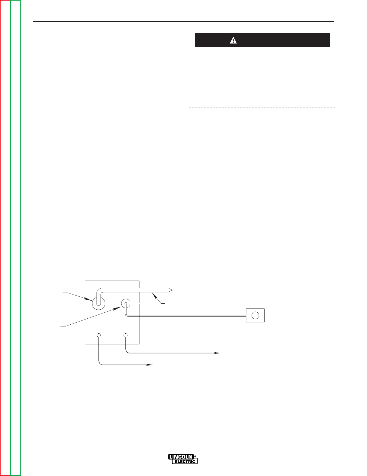
ACCESSORIES
C-6 C-6
RANGER 300 D AND 300 DLX
Return to Section TOC Return to Section TOC Return to Section TOC Return to Section TOC
Return to Master TOC Return to Master TOC Return to Master TOC Return to Master TOC
CONNECTION OF THE LN-7 TO THE
RANGER (300 DLX ONLY) USING K584
CONTROL CABLE (SEE FIGURE C.4.)
1. Shut the welder off.
2. Connect the electrode cable from the LN-7 to the
ELECTRODE terminal of the welder. Connect the
work cable to the WORK terminal of the welder.
NOTE: Welding cable must be sized for current and
duty cycle of application.
NOTE: Figure C.4 shows the electrode connected for
positive polarity. Use the Polarity switch on the Ranger
300 DLX to select the desired electrode polarity.
3. Connect the K584-XX Control Cable to the LN-7.
4. Connect the K584-XX Control Cable to the 14-pin
amphenol on the Ranger 300 DLX.
5. Place the IDLER switch in the “HIGH” position.
Any increase of the high idle engine RPM by changing
the governor setting or overriding the throttle linkage
will cause an increase in the AC auxiliary voltage. If
this voltage goes over 140 volts, wire feeder control
circuits may be damaged. The engine governor setting is preset at the factory - do not adjust above RPM
specifications listed in this manual.
6. Set the LOCAL/REMOTE switch to “REMOTE” if a
K857 remote control is used. Set the switch to
“LOCAL” if no remote control is used.
7. Set the OUTPUT RANGE switch to “WIRE WELDING CV.”
8. Set the WELDING TERMINALS switch to “WELDING TERMINALS REMOTELY CONTROLLED.”
9. Adjust wire feed speed at the LN-7.
NOTE: For remote control, a K857 remote control is
required. Connect it to the 6-pin amphenol.
FIGURE C.4
RANGER 300 DLX/LN-7 WITH K584 CONTROL CABLE CONNECTION DIAGRAM
CAUTION
ELECTRODE
TO WORK
TO LN-7 INPUT
CABLE PLUG
14 PIN
AMPHENOL
OPTIONAL K857
REMOTE CONTROL
6 PIN
AMPHENOL
ELECTRODE CABLE
TO WORK
TO WIRE FEED UNIT
K584 CONTROL CABLE
Page 42
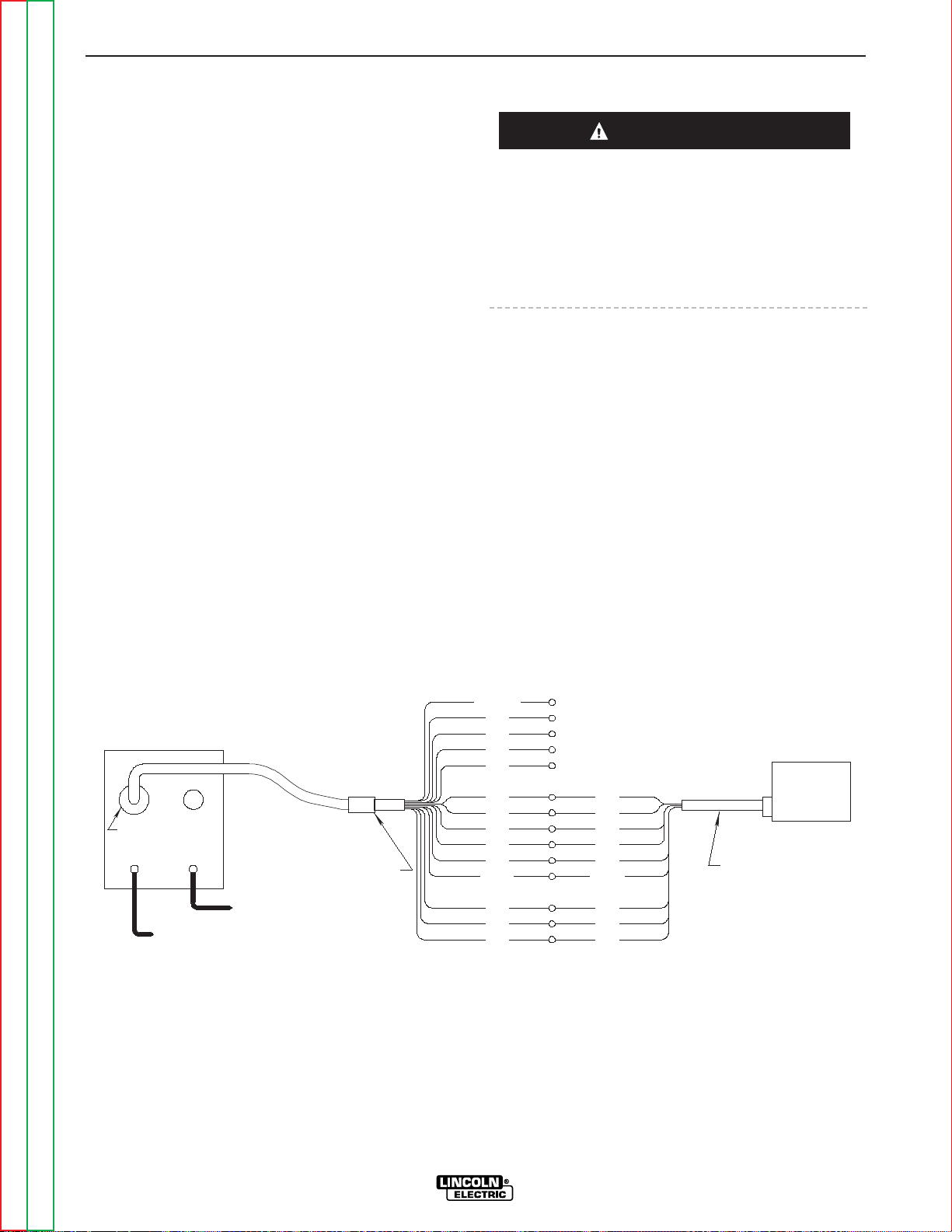
ACCESSORIES
C-7 C-7
RANGER 300 D AND 300 DLX
Return to Section TOC Return to Section TOC Return to Section TOC Return to Section TOC
Return to Master TOC Return to Master TOC Return to Master TOC Return to Master TOC
CONNECTION OF THE LN-8 TO THE
RANGER 300 (DLX ONLY) USING K867
UNIVERSAL ADAPTER (SEE FIGURE C.5.)
1. Shut the welder off.
2. Connect the electrode cable from the LN-8 to the
ELECTRODE terminal of the welder. Connect the
work cable to the WORK terminal of the welder.
NOTE: Welding cable must be sized for current and
duty cycle of application.
NOTE: Figure C.5 shows the electrode connected for
positive polarity. Use the Polarity switch on the
Ranger 300 to select the desired electrode polarity.
3. Connect the K867 Universal Adapter to the K196
input cable and the 14-pin amphenol of the Ranger
300 DLX as indicated in Figure C.5. Make the
proper connections for local or remote control
according to Figure C.5.
4. Connect the K196 input cable to the LN-8.
5. Place the IDLER switch in the “HIGH” position.
Any increase of the high idle engine RPM by changing
the governor setting or overriding the throttle linkage
will cause an increase in the AC auxiliary voltage. If
this voltage goes over 140 volts, wire feeder control
circuits may be damaged. The engine governor setting is preset at the factory - do not adjust above RPM
specifications listed in this manual.
6. Set the LOCAL/REMOTE switch to “REMOTE.”
7. Set the OUTPUT RANGE switch to “WIRE WELDING CV.”
8. Set the WELDING TERMINALS switch to “WELDING TERMINALS REMOTELY CONTROLLED.”
9. Adjust wire feed speed and voltage at the LN-8.
FIGURE C.5
RANGER 300 DLX/LN-8 WITH K867 ADAPTER CONNECTION DIAGRAM
+
14 PIN
AMPHENOL
CV-
TO WORK
WIRE
FEEDER
K196
K867 UNIVERSAL
ADAPTER PLUG
INPUT CABLE
ELECTRODE CABLE
TO WIRE FEED UNIT
2
4
76
77
SPARE
82
81
INSULATE UNUSED
LEADS INDIVIDUALLY
}
21
GND
SPLICE LEADS
AND INSULATE
32
2
}
LN-8
75
31
32
42
GND
31
4
21
B
C
A
41
CAUTION
Page 43

ACCESSORIES
C-8 C-8
RANGER 300 D AND 300 DLX
Return to Section TOC Return to Section TOC Return to Section TOC Return to Section TOC
Return to Master TOC Return to Master TOC Return to Master TOC Return to Master TOC
CONNECTION OF THE K488 SG
CONTROL MODULE AND K487 MAGNUM
SPOOL GUN TO THE RANGER 300
(DLX ONLY) (SEE FIGURE C.6.)
1. Shut the welder off.
2. Connect the electrode cable from the SG Control
Module to the ELECTRODE terminal of the welder.
Connect the work cable to the WORK terminal of
the welder.
NOTE: Welding cable must be sized for current and
duty cycle of application.
NOTE: Figure C.6 shows the electrode connected for
positive polarity. Use the Polarity switch on the Ranger
300 DLX to select the desired electrode polarity.
3. Connect the K691-10 Input Cable as shown in
Figure C.6.
4. Set the slide switch on the SG Control Module to
the “Lincoln” position.
Be sure the switch is set to the “Lincoln” (contact closure) position before attempting to operate the SG
Control Module. Incorrect switch position could result
in damage to the SG Control Module and/or the
Ranger 300 DLX.
5. Place the IDLER switch in the “HIGH” position.
Any increase of the high idle engine RPM by changing
the governor setting or overriding the throttle linkage
will cause an increase in the AC auxiliary voltage. If
this voltage goes over 140 volts, wire feeder control
circuits may be damaged. The engine governor setting is preset at the factory - do not adjust above RPM
specifications listed in this manual.
6. Set the LOCAL/REMOTE switch to “REMOTE” if a
K857 remote control is used. Set the switch to
“LOCAL” if no remote control is used.
7. Set the OUTPUT RANGE switch to “WIRE WELDING CV.”
8. Set the WELDING TERMINALS switch to “WELDING TERMINALS REMOTELY CONTROLLED.”
9. Adjust wire feed speed at the SG Control Module.
NOTE: For remote control, a K857 remote control is
required. Connect it to the 6-pin amphenol.
FIGURE C.6
RANGER 300 DLX/K691/K488/K487 SPOOL GUN CONNECTION DIAGRAM
K488 SG
TO WORK
CONTROL MODULE
RECEPTACLE
14 PIN WIRE FEEDER
RANGER
115V RECEPTACLE
K487-25
SPOOL GUN
ELECTRODE
INPUT CABLE
K691-10
6 PIN REMOTE
TO CONTROL MODULE
ELECTRODE CABLE
RECEPTACLE
TO WORK
CAUTION
CAUTION
Page 44

CONNECTION OF THE K930-1 TIG
MODULE TO THE RANGER 300 (DLX
ONLY) USING K936 CONTROL CABLE
(SEE FIGURE C.7.)
1. Shut the welder off.
2. Connect the electrode cable from the K930-1 TIG
Module to the ELECTRODE terminal of the welder.
Connect the work cable to the WORK terminal of
the welder.
NOTE: Welding cable must be sized for current and
duty cycle of application.
NOTE: Figure C.7 shows the electrode connected for
positive polarity. Use the Polarity switch on the Ranger
300 DLX to select the desired electrode polarity.
3. Connect the K936-1 Control Cable to the K930-1
TIG Module and to the 14-pin amphenol on the
Ranger 300 DLX.
4. Connect the K870 Foot Amptrol or K963-1 Hand
Amptrol or K814 Arc Start Switch to the K930-1
TIG Module.
5. Place the IDLER switch in the “AUTO” or “HIGH”
position as desired.
Any increase of the high idle engine RPM by changing
the governor setting or overriding the throttle linkage
will cause an increase in the AC auxiliary voltage. If
this voltage goes over 140 volts, wire feeder control
circuits may be damaged. The engine governor setting is preset at the factory - do not adjust above RPM
specifications listed in this manual.
6. Set the LOCAL/REMOTE switch to “REMOTE.”
7. Set the OUTPUT RANGE switch to “STICK WELDING.”
8. Set the WELDING TERMINALS switch to “WELDING TERMINALS REMOTELY CONTROLLED.”
ACCESSORIES
C-9 C-9
RANGER 300 D and 300 DLX
Return to Section TOC Return to Section TOC Return to Section TOC Return to Section TOC
Return to Master TOC Return to Master TOC Return to Master TOC Return to Master TOC
FIGURE C.7
RANGER 300 DLX/K930-1 TIG MODULE CONNECTION DIAGRAM
14 PIN
AMPHENOL
ELECTRODE
K963-1 HAND AMPTROL
-OR-
-OR-
K814 ARC START SWITCH
K870 FOOT AMPTROL
FLOWMETER
K936-1
CONTROL CABLE
INPUT
REGULATOR
TO GAS
FITTING
CYLINDER
ARGON GAS
TO WORK
CAUTION
Page 45

NOTES
RANGER 300 D AND 300 DLX
Return to Section TOC Return to Section TOC Return to Section TOC Return to Section TOC
Return to Master TOC Return to Master TOC Return to Master TOC Return to Master TOC
Page 46

Return to Master TOC Return to Master TOC Return to Master TOC Return to Master TOC
Section D-1 Section D-1
RANGER 300 D AND 300 DLX
TABLE OF CONTENTS
-MAINTENANCE-
Maintenance .........................................................................................................................Section D
Safety Precautions......................................................................................................................D-2
Kubota Engine Maintenance Schedule .....................................................................................D-2
Kubota Engine Maintenance Components ...............................................................................D-2
Routine and Periodic Maintenance ...........................................................................................D-3
Engine Maintenance.............................................................................................................D-3
Oil ..................................................................................................................................D-3
Changing the Oil ............................................................................................................D-3
Oil Filter ..........................................................................................................................D-3
Fuel.................................................................................................................................D-4
Bleeding the Fuel System ..............................................................................................D-4
Air Cleaner......................................................................................................................D-4
Tightening the Fan Belt .................................................................................................D-4
Cooling System..............................................................................................................D-4
Spark Arrester Screen....................................................................................................D-5
Battery Maintenance ............................................................................................................D-5
Cleaning the Battery ......................................................................................................D-5
Checking Specific Gravity..............................................................................................D-5
Checking Electrolyte Level.............................................................................................D-5
Charging the Battery......................................................................................................D-6
Welder/Generator Maintenance ...........................................................................................D-6
Storage...........................................................................................................................D-6
Cleaning .........................................................................................................................D-6
Brush Removal and Replacement ................................................................................D-6
Nameplates ....................................................................................................................D-6
Receptacles ...................................................................................................................D-6
Cable Connections.........................................................................................................D-6
Major Component Locations ...............................................................................................D-7
Page 47
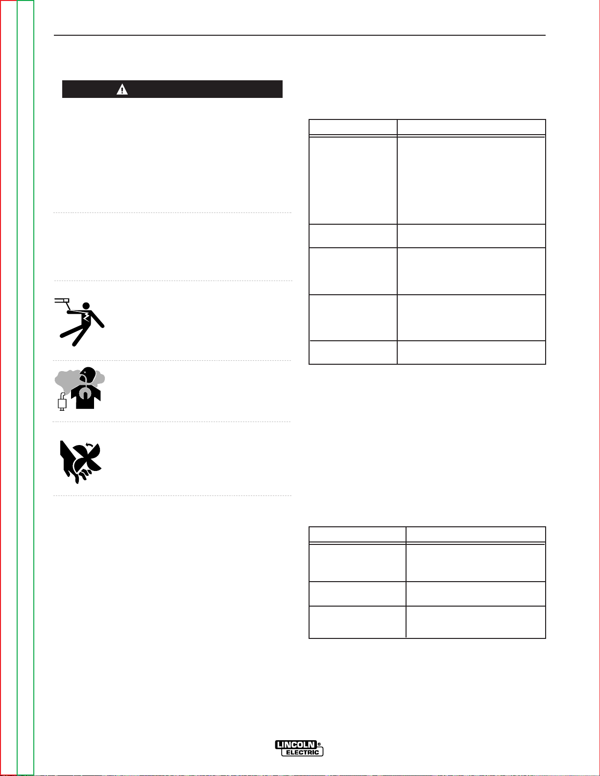
SAFETY PRECAUTIONS
Have qualified personnel do the maintenance work.
Turn the engine off before working inside the machine.
In some cases, it may be necessary to remove safety
guards to perform required maintenance. Remove
guards only when necessary and replace them when
the maintenance requiring their removal is complete.
Always use the greatest care when working near moving parts.
Do not put your hands near the engine cooling blower
fan. If a problem cannot be corrected by following the
instructions, take the machine to the nearest Lincoln
Field Service Shop.
ELECTRIC SHOCK can kill.
• Do not touch electrically live parts or
electrode with skin or wet clothing.
• Insulate yourself from work and ground
• Always wear dry insulating gloves.
ENGINE EXHAUST can kill.
• Use in open, well ventilated areas or
vent exhaust outside.
MOVING PARTS can injure.
• Do not operate with doors open or
guards off.
• Stop engine before servicing.
• Keep away from moving parts.
See additional warning information throughout this
operator’s manual and the Kubota Engine
Operator’s Manual as well.
KUBOTA ENGINE MAINTENANCE
SCHEDULE
TABLE D.1
(1) Replace air filter element after 600 hours of operation or sooner under
dusty operating conditions.
(2) If the engine is operated under heavy load, in high ambient temperatures,
or under dusty conditions, change the oil and oil filter every 100 hours.
Refer to your Kubota Engine Operator's Manual for
periodic maintenance at 500 hours and beyond.
KUBOTA ENGINE MAINTENANCE
COMPONENTS
TABLE D.2
MAINTENANCE
D-2 D-2
RANGER 300 D AND 300 DLX
Return to Section TOC Return to Section TOC Return to Section TOC Return to Section TOC
Return to Master TOC Return to Master TOC Return to Master TOC Return to Master TOC
WARNING
FREQUENCY
Daily or Before
Starting Engine
Every 50 Hours
Every 100 Hours
Every 200 Hours
Every 400 Hours
MAINTENANCE REQUIRED
• Fill fuel tank.
• Check oil level.
• Check air cleaner for dirty,
loose, or damaged parts.
• Check air intake and cooling
areas, clean as necessary.
• Check fuel lines and clamps.
• Clean air filter element.
(1)
• Check battery electrolyte level.
• Check fan belt tightness.
• Change engine oil.
(2)
• Replace oil filter cartridge.
(2)
• Check radiator hoses.
• Replace fuel filter element.
ITEM
Oil Filter Element
Air Cleaner Element
Fuel Filter Element
MAKE AND PART NUMBER
Kubota 16271-32092
Fram PH 3593A
Donaldson P148970
Kubota 15231-43560
Fram C6921
Page 48
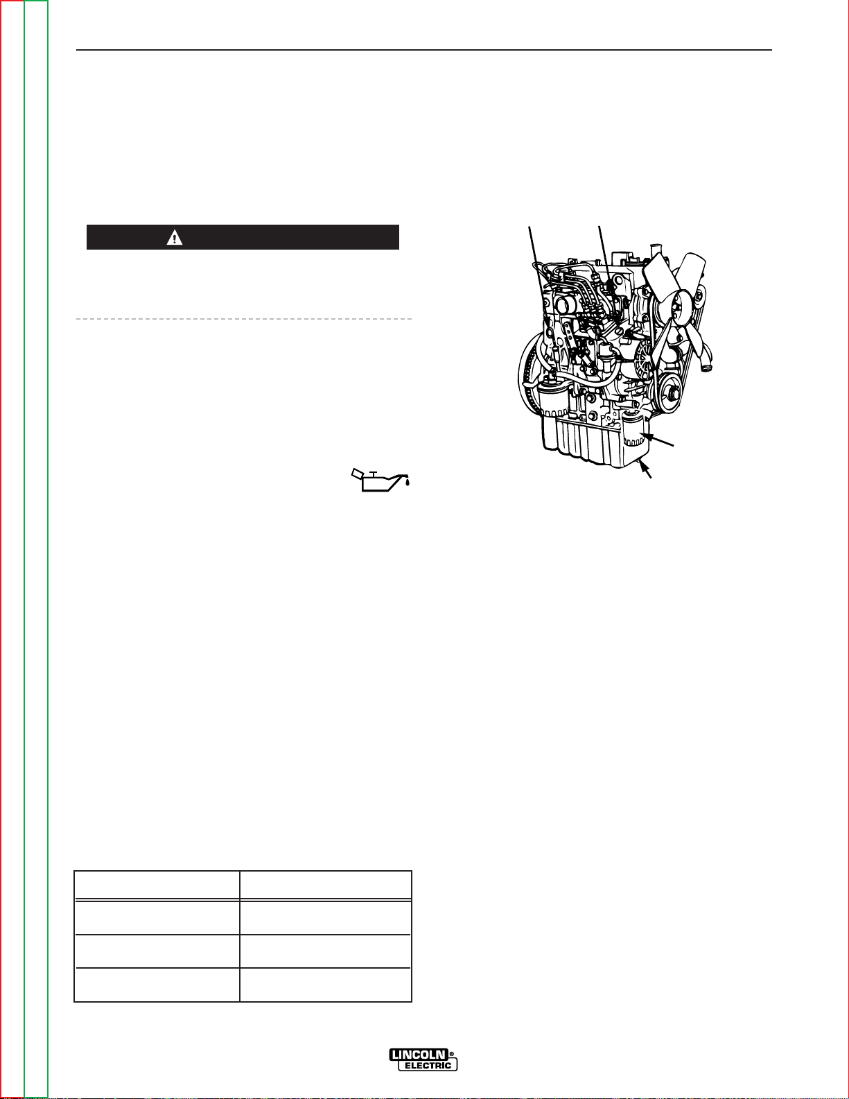
ROUTINE AND PERIODIC
MAINTENANCE
ENGINE MAINTENANCE
(Refer to Figure D.3 for the location of maintenance
components.)
To prevent the engine from accidentally starting, disconnect the negative battery cable before servicing the
engine.
See Table D.1 for a summary of maintenance intervals
for the items listed below. More frequent service may
be required, depending on your specific application
and operating conditions. See the Kubota Engine
Operator's Manual for further information.
OIL
Check the oil level before starting engine or
daily. BE SURE TO MAINTAIN THE OIL
LEVEL. Change the oil for the first time after 50 hours
of operation. Then, under normal operating conditions, change the oil as specified in the maintenance
schedule.
CHANGING THE OIL
Change the oil, while the engine is still warm, as follows:
1. Drain the oil from the drain plug located on the
engine bottom, as shown in Figure D.1.
2. Replace the plug and tighten it securely.
3. Remove the oil fill cap and add oil until the level
reaches the full mark on the dipstick. The quantity
of oil required for an oil and oil filter change is 5.4
quarts (5.1 L). Use oil that is rated for diesel engine
service (API classification CD/CE). Use SAE viscosity grades per Table D.3.
TABLE D.3
4. Reinstall the oil fill cap and the dipstick and start
the engine. Run for several minutes and stop
engine. Wait 5 minutes to allow the oil to come
down to the oil pan and check oil level again.
FIGURE D.1
OIL COMPONENT LOCATIONS
OIL FILTER
Change the oil filter the first time after 50 hours of
operation. Then, under normal operating conditions,
change the oil filter at every oil change. See Table D.2
for recommended oil filters.
Change the oil filter as follows:
1. Drain the oil from the engine and allow the oil filter
to drain.
2. Remove the old filter (spin it off) and discard it.
Wipe off the filter mounting surface and adapter.
3. Apply a thin coat of new oil to the rubber gasket on
the new oil filter.
4. Spin the new filter on to the mounting adapter until
the gasket just touches the mounting surface, then
turn it down another 1/2 to 3/4 turn. Do not overtighten the new filter.
5. Refill the engine with the proper amount and type
of oil as described in the Changing the Oil section.
Start the engine and check for leaks around the filter element. Correct any leaks (usually by retightening the filter, but only enough to stop leaks)
before placing the RANGER 300 back in service.
6. If there are no leaks, stop the engine and recheck
the oil level. If necessary, add oil to bring the level
up to the FULL mark, but do not overfill.
MAINTENANCE
D-3 D-3
RANGER 300 D AND 300 DLX
Return to Section TOC Return to Section TOC Return to Section TOC Return to Section TOC
Return to Master TOC Return to Master TOC Return to Master TOC Return to Master TOC
CAUTION
Ambient Temperature
Above 25°C (77°F)
0°C (32°F) to 25°C (77°F)
Below 0°C (32°F)
Viscosity Grades
SAE 10W-30, SAE10W-40 or SAE30
SAE 10W-30, SAE10W-40 or SAE20
SAE 10W-30, SAE10W-40 or SAE10
OIL DRAIN PLUG
OIL FILTER
OIL FILL CAP
OIL LEVEL
DIP STICK
Page 49
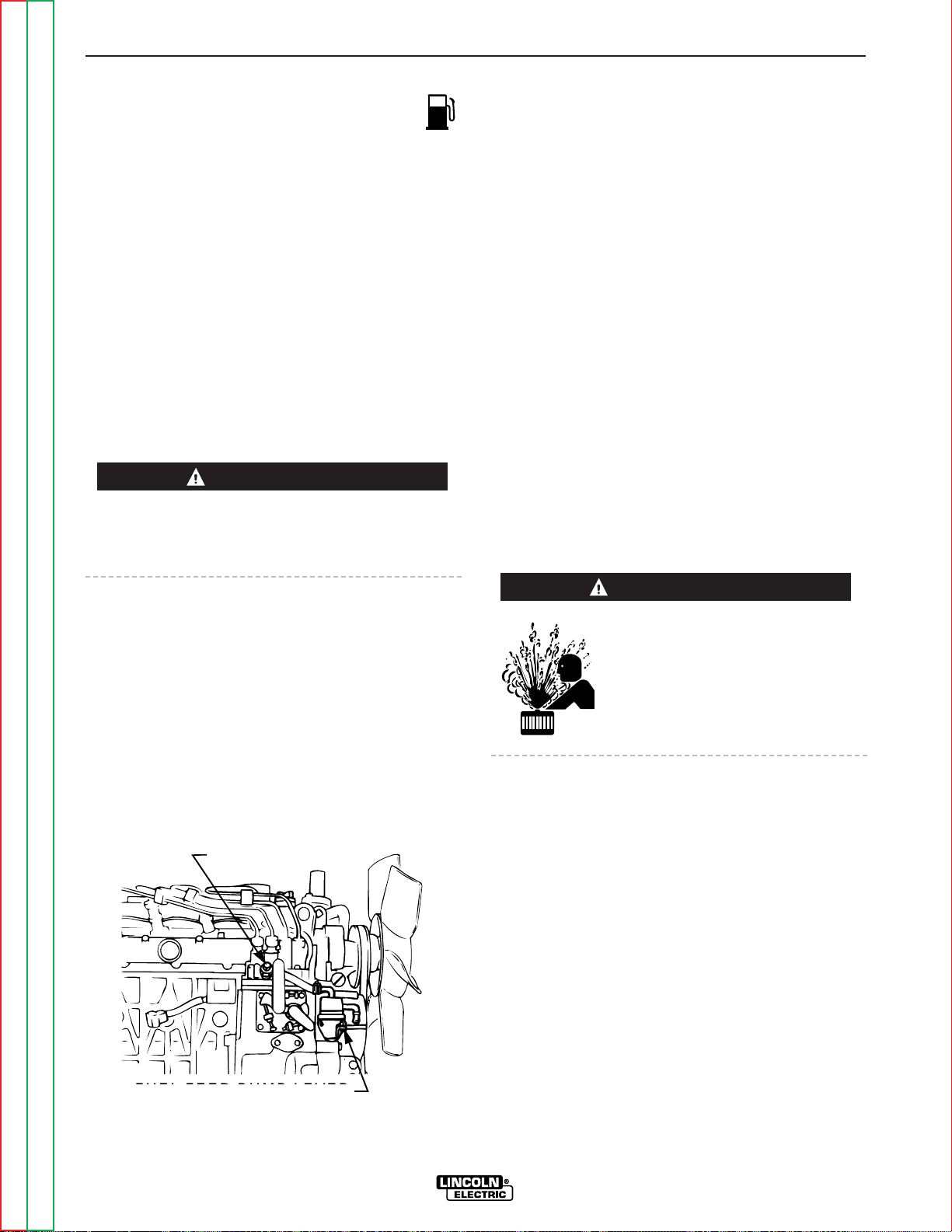
FUEL
At the end of each day’s use, refill the fuel tank
to minimize moisture condensation and dirt contamination in the fuel line. Do not overfill; leave room for
the fuel to expand.
Use only fresh, No. 2 grade DIESEL fuel. Do not use
kerosene.
See the Kubota Engine Operator's Manual for instructions on replacing the fuel filter. See Table D.2 for recommended fuel filters.
BLEEDING THE FUEL SYSTEM
You will need to bleed air from the fuel system any
time the fuel filter or fuel lines have been detached and
refitted; after the fuel tank has been run out of fuel; or
before using the engine after long storage. Bleed the
fuel system as follows:
To avoid personal injury, do not bleed a hot engine.
This could cause fuel to spill onto a hot exhaust manifold, creating a danger of fire.
Refer to Figure D.2
1. Fill the fuel tank. Open the fuel cock.
2. Open the air vent plug on the fuel injection pump
two turns using a 10mm wrench.
3. Move the fuel feed pump lever by hand until fuel
flows out of the air vent plug.
4. Tighten the air vent plug.
FIGURE D.2
FUEL BLEEDING COMPONENT LOCATIONS
AIR CLEANER
The Kubota diesel engine is equipped with a dry type air
filter. Never apply oil to it. See Table D.2 for recom-
mended air cleaner. Service the air cleaner as follows:
1. Remove the dust cup from the bottom of the air
cleaner housing. Clean out any accumulated dust.
2. If dust is sticking to the element, blow compressed
air through the element from the inside out. Turn
the element as you apply air. Air pressure should
be under 99 psi (68 newton/cm
2
). Replace the fil-
ter if there is carbon or oil on the element.
3. Replace the element at least every 600 hours of
operation and sooner under dusty conditions.
TIGHTENING THE FAN BELT
If the fan belt is loose, the engine can overheat and the
battery lose its charge. Check tightness by pressing
on the belt midway between the pulleys. It should
deflect about .25 in. (6 mm) under a load of 20 lbs.
(9 Kg).
COOLING SYSTEM
HOT COOLANT can burn skin.
• Do not remove cap if radiator is
hot.
Check the coolant level by observing the level in the
plastic reserve overflow tank. Add 50/50 antifreeze/
water solution if the level is close to or below the
“LOW” mark. Do not fill above the “FULL” mark.
Remove radiator cap and add coolant to radiator if
overflow tank is empty.
To drain the coolant, open the petcock at the bottom
of the radiator. Open the radiator cap to allow complete drainage. (Tighten the petcock and refill with a
50/50 antifreeze/water solution.) Use an automotive
grade (low silicate) ethylene glycol antifreeze. The
cooling system capacity is 5.4 quarts (5.1l.). Replace
and tighten the radiator cap.
MAINTENANCE
D-4 D-4
RANGER 300 D AND 300 DLX
Return to Section TOC Return to Section TOC Return to Section TOC Return to Section TOC
Return to Master TOC Return to Master TOC Return to Master TOC Return to Master TOC
WARNING
AIR VENT PLUG
FUEL FEED PUMP LEVER
WARNING
AIR VENT PLUG
FUEL FEED PUMP LEVER
Page 50

Always premix the antifreeze and clean tap water
before adding to the radiator or the overflow tank. It is
very important that a precise 50/50 solution be used
with this engine year round. This gives proper cooling
during hot weather and freezing protection to -34°F
(-37°C).
Cooling solution exceeding 50% ethylene glycol can
result in engine overheating and damage to the
engine. Coolant solution must be premixed before
adding to radiator.
Periodically remove the dirt from the radiator fins.
Periodically check the fan belt and radiator hoses.
Replace if signs of deterioration are found.
SP ARK ARRESTER SCREEN
If the muffler has the optional spark arrester, remove it
every 50 hours or once a year, whichever comes first,
and inspect it. Clean the arrester. Replace it if you find
any damage.
BATTERY MAINTENANCE
GASES FROM BATTERY can explode.
• Keep sparks, flame and cigarettes
away from battery.
To prevent EXPLOSION when:
• INSTALLING A NEW BATTERY – disconnect neg-
ative cable from old battery first and connect to
new battery last.
• CONNECTING A BATTERY CHARGER – remove
battery from welder by disconnecting negative
cable first, then positive cable and battery clamp.
When reinstalling, connect negative cable last.
Keep well ventilated.
• USING A BOOSTER – connect positive lead to
battery first then connect negative lead to negative
battery lead at engine foot.
BATTERY ACID can burn eyes and skin.
•Wear gloves and eye protection and
be careful when working near battery.
• Follow instructions printed on battery.
To prevent ELECTRICAL DAMAGE when:
a) Installing a battery.
b) Using a booster.
Use correct polarity - Negative Ground.
To prevent BATTERY DISCHARGE, if you have an ignition switch, turn it off when engine is not running.
CLEANING THE BATTERY
Keep the battery clean by wiping it with a damp cloth
when dirty. If the terminals appear corroded, disconnect the battery cables and wash the terminals with an
ammonia solution or a solution of 1/4 pound (0.1113
kg) of baking soda and 1 quart (0.946 l) of water. Be
sure the battery vent plugs (if equipped) are tight so
that none of the solution enters the cells.
After cleaning, flush the outside of the battery, the battery compartment, and surrounding areas with clean
water. Coat the battery terminals lightly with petroleum jelly or a non-conductive grease to retard corrosion.
Keep the battery clean and dry. Moisture accumulation
on the battery can lead to more rapid discharge and
early battery failure.
CHECKING SPECIFIC GRAVITY
Check each battery cell with a hydrometer. A fully
charged battery will have a specific gravity of 1.260.
Charge the battery if the reading is below 1.215.
NOTE: Correct the specific gravity reading by adding
four gravity points (0.004) for every five degrees the
electrolyte temperature is above 80°F (27°C). Subtract
four gravity points (9.004) for every five degrees the
electrolyte temperature is below 80°F (27°C).
CHECKING ELECTROLYTE LEVEL
If battery cells are low, fill them to the neck of the filler
hole with distilled water and recharge. If one cell is low,
check for leaks.
The battery is a group 45, with a rating of 495 cold
cranking amps.
MAINTENANCE
D-5 D-5
RANGER 300 D AND 300 DLX
Return to Section TOC Return to Section TOC Return to Section TOC Return to Section TOC
Return to Master TOC Return to Master TOC Return to Master TOC Return to Master TOC
CAUTION
CAUTION
Page 51

Return to Section TOC Return to Section TOC Return to Section TOC Return to Section TOC
Return to Master TOC Return to Master TOC Return to Master TOC Return to Master TOC
MAINTENANCE
D-6 D-6
RANGER 300 D AND 300 DLX
CHARGING THE BATTERY
When you charge, jump, replace, or otherwise connect
battery cables to the battery, be sure the polarity is
correct. Improper polarity can damage the charging
circuit. The RANGER 300 positive (+) battery terminal
has a red terminal cover.
If you need to charge the battery with an external
charger, disconnect the negative cable first, then the
positive cable before you attach the charger leads.
after the battery is charged, reconnect the positive
battery cable first and the negative cable last. Failure
to do so can result in damage to the internal charger
components.
Follow the instructions of the battery charger manufacturer for proper charger settings and charging time.
WELDER / GENERATOR
MAINTENANCE
STORAGE
Store the RANGER 300 in clean, dry protected areas.
CLEANING
Blow out the generator and controls periodically with
low pressure air. Do this at least once a week in particularly dirty areas.
BRUSH REMOVAL AND REPLACEMENT
It is normal for the brushes and slip rings to wear and
darken slightly. Inspect the brushes when a generator
overhaul is necessary.
Do not attempt to polish slip rings while the engine is
running.
NAMEPLATES
Whenever routine maintenance is performed on this
machine - or at least yearly - inspect all nameplates
and labels for legibility. Replace nameplates that are
no longer clear. Refer to the parts list for the replacement item number.
RECEPTACLES
Keep the electrical receptacles in good condition.
Remove any dirt, oil, or other debris from their surfaces and holes.
CABLE CONNECTIONS
Check the welding cable connections at the weld output terminals often. Be sure that the connections are
always firm.
WARNING
Page 52

Return to Section TOC Return to Section TOC Return to Section TOC Return to Section TOC
Return to Master TOC Return to Master TOC Return to Master TOC Return to Master TOC
MAINTENANCE
D-7 D-7
RANGER 300 D AND 300 DLX
FIGURE D.3
MAJOR COMPONENT LOCATIONS
11. CAPACITOR BANK (RANGER 300 DLX ONLY)
12. RADIATOR ASSEMBLY
13. CHOKE ASSEMBLY
14. LIFT BAIL WELDED ASSEMBLY
15. CASE BACK ASSEMBLY
16. FIELD CAPACITOR AND
RECTIFIER BRIDGE
17. CONTACTOR (RANGER 300 DLX ONLY)
18. FUEL SHUTOFF & IDLER ASSEMBLY
19. CASE TOP
20. DOOR ASSEMBLY
1. OUTPUT TERMINALS
2. ENGINE CONTROLS
3. AUXILIARY POWER RECEPTACLES
4. OUTPUT CONTROL PANEL
5. REACTOR ASSEMBLY
6. FUEL TANK
7. DIESEL ENGINE
8. ROTOR/STATOR ASSEMBLY
9. BASE WELDED ASSEMBLY
10. P.C. BOARD COVER
19
6
10
17
16
13
4
3
2
1
9
11
20
5
12
18
8
15
7
14
Page 53

NOTES
RANGER 300 D AND 300 DLX
Return to Section TOC Return to Section TOC Return to Section TOC Return to Section TOC
Return to Master TOC Return to Master TOC Return to Master TOC Return to Master TOC
Page 54

Return to Master TOC Return to Master TOC Return to Master TOC Return to Master TOC
Section E-1 Section E-1
RANGER 300 D AND 300 DLX
Theory of Operation .............................................................................................................Section E
Battery, Starter, Engine, Glow Plugs, Engine Protection, Rotor, Stator, and
Idler Solenoid ..............................................................................................................................E-2
Rotor Field Feedback, Auxiliary and Wire Feeder Power...........................................................E-3
Weld Winding, Reactor, and Range Switch ................................................................................E-4
Output Bridge, Choke, Polarity Switch, CV Contactor, and Output Terminals ..........................E-5
TABLE OF CONTENTS
-THEORY OF OPERATION SECTION-
RANGE
SWITCH
REACTOR
STATOR
ROTOR
MECHANICAL
ROTATION
ENGINE
GLOW PLUGS
BATTERY
6 PIN
AMPHENOL
14 PIN
AMPHENOL
OUTPUT
CONTROL
REMOTE
SWITCH
BY-PASS
BOARD
SHUTDOWN
SOLENOID
STARTER
MOTOR
ALTERNATOR
IDLER
SOLENOID
PRINTED
CIRCUIT
BOARD
FIELD
CAPACITOR
FIELD
BRIDGE
115 & 230VAC
RECEPTACLES
AC
AC
OUTPUT
RECTIFIER
BRIDGE
CAPACITORS
PART OF
RANGE
SWITCH
CHOKE
POLARITY
SWITCH
WORK
TERMINAL
ELECTRODE
TERMINAL
CONTACTOR CLOSURE
ROTOR
SLIP
RINGS
42VAC
115VAC
cv
output
contactor
CONTACTOR CLOSURE
OIL &
WATER
SENSORS
RANGER 300 DLX
FIGURE E.1
RANGER 300 BLOCK LOGIC DIAGRAM
Page 55
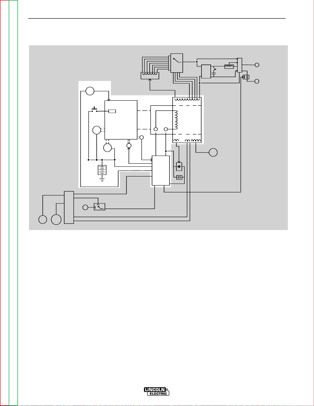
BATTERY, STARTER, ENGINE,
GLOW PLUGS, ENGINE
PROTECTION, ROTOR, STATOR
AND IDLER SOLENOID
The 12VDC battery powers the starter motor and glow
plugs. The glow plugs are used to preheat the diesel
engine to enhance starting. When the engine is started and running, the battery circuit voltage is fed
through the printed circuit board to the rotating field
coil in the rotor via a brush and slip ring configuration.
This excitation (“flashing”) voltage magnetizes the
rotor lamination. The rotor is mechanically coupled to
the engine. This rotating magnet induces a voltage in
the stationary windings of the main alternator (stator).
There are four separate and isolated windings incorporated in the stator lamination assembly. Each set has
a different number of turns producing different magnitudes of AC output voltages. These four windings are
the weld winding, the auxiliary power winding, the field
feedback winding and the auxiliary power winding for
wire feeders. The field feedback winding provides
rotor current during machine operation. The output of
the Ranger 300 is dependent on two criteria, the
engine RPM and the amount of current in the rotor
winding.
The engine alternator supplies “charging” current for
the battery circuit. The battery circuit provides power
for the printed circuit board and also for the idler solenoid. The idler solenoid is mechanically connected to
the engine's throttle linkage. If welding or auxiliary
current is being drawn from the Ranger 300, the printed circuit board activates the idler solenoid, which
then brings the engine to the high RPM state. When
no output current is sensed, either weld or auxiliary,
the printed circuit board deactivates the idler solenoid
and the engine returns to low RPM.
The engine protection circuit shuts the engine off in the
event of low oil pressure or engine coolant over-temperature.
THEORY OF OPERATION
E-2 E-2
RANGER 300 D AND 300 DLX
Return to Section TOC Return to Section TOC Return to Section TOC Return to Section TOC
Return to Master TOC Return to Master TOC Return to Master TOC Return to Master TOC
FIGURE E.2
BATTERY, STARTER, ENGINE, GLOW PLUGS,ENGINE PROTECTION,
ROTOR, STATOR AND IDLER SOLENOID
NOTE: Unshaded areas of Block Logic Diagram are the subject of discussion.
RANGE
SWITCH
REACTOR
STATOR
ROTOR
MECHANICAL
ROTATION
ENGINE
GLOW PLUGS
BATTERY
6 PIN
AMPHENOL
14 PIN
AMPHENOL
OUTPUT
CONTROL
REMOTE
SWITCH
BY-PASS
BOARD
SHUTDOWN
SOLENOID
STARTER
MOTOR
ALTERNATOR
IDLER
SOLENOID
PRINTED
CIRCUIT
BOARD
FIELD
CAPACITOR
FIELD
BRIDGE
115 & 230VAC
RECEPTACLES
AC
AC
OUTPUT
RECTIFIER
BRIDGE
CAPACITORS
PART OF
RANGE
SWITCH
CHOKE
POLARITY
SWITCH
WORK
TERMINAL
ELECTRODE
TERMINAL
CONTACTOR CLOSURE
ROTOR
SLIP
RINGS
42VAC
115VAC
cv
output
contactor
CONTACTOR CLOSURE
OIL &
WATER
SENSORS
RANGER 300 DLX
Page 56

ROTOR FIELD FEEDBACK,
AUXILIARY AND WIRE FEEDER
POWER
The AC voltage developed in the field winding is fed to
the full wave field bridge. The DC output of the field
bridge is filtered by the field capacitor and controlled
by the printed circuit board according to the setting of
the machine’s output control or remote control. This
filtered and controlled voltage is fed to the rotor winding via the brush and slip ring configuration. As the
feedback voltage is increased or decreased, the outputs of the weld and auxiliary windings are increased
or decreased.
When full field voltage is applied to the rotor and the
engine is running at high speed (3600 RPM), a 230VAC
voltage is developed in the stator auxiliary winding.
This winding is tapped to provide 115VAC. The two
voltages (115VAC and 230VAC), are connected to the
appropriate receptacles and offer 12,000 watts (total)
of AC power.
The auxiliary wire feeder winding offers 115VAC and is
tapped to also provide 42VAC. The current draw from
this winding should be limited to 8 amps. These voltages and remote control signals are fed through the
by-pass (filter) board to the amphenol receptacles.
THEORY OF OPERATION
E-3 E-3
RANGER 300 D AND 300 DLX
Return to Section TOC Return to Section TOC Return to Section TOC Return to Section TOC
Return to Master TOC Return to Master TOC Return to Master TOC Return to Master TOC
NOTE: Unshaded areas of Block Logic Diagram are the subject of discussion.
FIGURE E.3
ROTOR FIELD FEEDBACK, AUXILIARY AND WIRE FEEDER POWER
RANGE
SWITCH
REACTOR
STATOR
ROTOR
MECHANICAL
ROTATION
ENGINE
GLOW PLUGS
BATTERY
6 PIN
AMPHENOL
14 PIN
AMPHENOL
OUTPUT
CONTROL
REMOTE
SWITCH
BY-PASS
BOARD
SHUTDOWN
SOLENOID
STARTER
MOTOR
ALTERNATOR
IDLER
SOLENOID
PRINTED
CIRCUIT
BOARD
FIELD
CAPACITOR
FIELD
BRIDGE
115 & 230VAC
RECEPTACLES
AC
AC
OUTPUT
RECTIFIER
BRIDGE
CAPACITORS
PART OF
RANGE
SWITCH
CHOKE
POLARITY
SWITCH
WORK
TERMINAL
ELECTRODE
TERMINAL
CONTACTOR CLOSURE
ROTOR
SLIP
RINGS
42VAC
115VAC
cv
output
contactor
CONTACTOR CLOSURE
OIL &
WATER
SENSORS
RANGER 300 DLX
Page 57
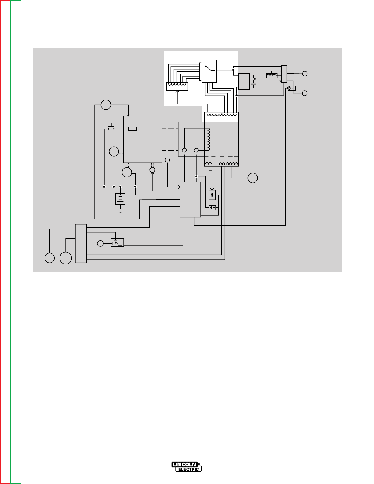
WELD WINDING, REACTOR AND
RANGE SWITCH
The stator weld winding is connected to the reactor
and range switch. The inductance in the reactor offers
an impedance to current flow. The reactor coil is
tapped at various points. As the range switch is rotated, different amounts of reactor coil are brought into
the current path. As more turns of reactor are brought
into the circuit, the more impedance there is to current
flow. Simply stated, the more reactor in the circuit, the
lower the welding current.
If a constant voltage is desired for wire feeding, then
the reactor is bypassed, and the range switch is connected to one of four taps on the stator weld winding
to provide a lower but “stiffer” output voltage.
THEORY OF OPERATION
E-4 E-4
RANGER 300 D AND 300 DLX
Return to Section TOC Return to Section TOC Return to Section TOC Return to Section TOC
Return to Master TOC Return to Master TOC Return to Master TOC Return to Master TOC
FIGURE E-4
WELD WINDING, REACTOR AND RANGE SWITCH
NOTE: Unshaded areas of Block Logic Diagram are the subject of discussion.
RANGE
SWITCH
REACTOR
STATOR
ROTOR
MECHANICAL
ROTATION
ENGINE
GLOW PLUGS
BATTERY
6 PIN
AMPHENOL
14 PIN
AMPHENOL
OUTPUT
CONTROL
REMOTE
SWITCH
BY-PASS
BOARD
SHUTDOWN
SOLENOID
STARTER
MOTOR
ALTERNATOR
IDLER
SOLENOID
PRINTED
CIRCUIT
BOARD
FIELD
CAPACITOR
FIELD
BRIDGE
115 & 230VAC
RECEPTACLES
AC
AC
OUTPUT
RECTIFIER
BRIDGE
CAPACITORS
PART OF
RANGE
SWITCH
CHOKE
POLARITY
SWITCH
WORK
TERMINAL
ELECTRODE
TERMINAL
CONTACTOR CLOSURE
ROTOR
SLIP
RINGS
42VAC
115VAC
cv
output
contactor
CONTACTOR CLOSURE
OIL &
WATER
SENSORS
RANGER 300 DLX
Page 58

OUTPUT BRIDGE, CHOKE,
POLARITY SWITCH, OUTPUT
CONTACTOR AND OUTPUT
TERMINALS
The AC voltage developed in the stator weld winding
is delivered, through the reactor and range switch, to
the output bridge and polarity switch. Depending
upon the setting of the polarity switch, either AC voltage or DC voltage is delivered to the output terminals.
If AC output is selected, the current path is from the
stator weld winding through the reactor, range switch,
and polarity switch; through the output contactor to
the output terminals. If a DC output is called for, the
current path is through the output rectifier bridge,
where the AC voltage is rectified to a DC voltage; and
then to the choke, where the DC output is filtered. The
filtered DC current path is through the polarity switch
and output contactor to the output terminals.
When a CV (constant voltage) is desired, the reactor is
passed by. The range switch applies a lower AC voltage to the rectifier bridge. The DC output of the bridge
is filtered and “stiffened” by the capacitors. This lower
but “stiffer” DC output is passed through the tapped
portion of the choke, the polarity switch, and output
contactor to the output terminals.
In the Ranger 300DLX machines, the output contactor
is in series with the electrode terminal and must be
energized (closed) to provide welding voltage at the
output terminals.
THEORY OF OPERATION
E-5 E-5
RANGER 300 D AND 300 DLX
Return to Section TOC Return to Section TOC Return to Section TOC Return to Section TOC
Return to Master TOC Return to Master TOC Return to Master TOC Return to Master TOC
RANGE
SWITCH
REACTOR
STATOR
ROTOR
MECHANICAL
ROTATION
ENGINE
GLOW PLUGS
BATTERY
6 PIN
AMPHENOL
14 PIN
AMPHENOL
OUTPUT
CONTROL
REMOTE
SWITCH
BY-PASS
BOARD
SHUTDOWN
SOLENOID
STARTER
MOTOR
ALTERNATOR
IDLER
SOLENOID
PRINTED
CIRCUIT
BOARD
FIELD
CAPACITOR
FIELD
BRIDGE
115 & 230VAC
RECEPTACLES
AC
AC
OUTPUT
RECTIFIER
BRIDGE
CAPACITORS
PART OF
RANGE
SWITCH
CHOKE
POLARITY
SWITCH
WORK
TERMINAL
ELECTRODE
TERMINAL
CONTACTOR CLOSURE
ROTOR
SLIP
RINGS
42VAC
115VAC
cv
output
contactor
CONTACTOR CLOSURE
OIL &
WATER
SENSORS
RANGER 300 DLX
FIGURE E.5 – OUTPUT BRIDGE, CHOKE, POLARITY SWITCH, OUTPUT CONTACTOR
AND OUTPUT TERMINALS
NOTE: Unshaded areas of Block Logic Diagram are the subject of discussion.
Page 59

NOTES
RANGER 300 D AND 300 DLX
Return to Section TOC Return to Section TOC Return to Section TOC Return to Section TOC
Return to Master TOC Return to Master TOC Return to Master TOC Return to Master TOC
Page 60

Return to Master TOC Return to Master TOC Return to Master TOC Return to Master TOC
Section F-1 Section F-1
RANGER 300 D AND 300 DLX
Troubleshooting & Repair Section.................................................................................Section F
How to Use Troubleshooting Guide ......................................................................................F-2
PC Board Troubleshooting Procedures .................................................................................F-3
Troubleshooting Guide.................................................................................................F4 - F-20
Test Procedures ...................................................................................................................F-21
Rotor Resistance Test ..................................................................................................F-21
Output Rectifier Bridge Test .........................................................................................F-23
Fuel Shutdown Solenoid Resistance Test ...................................................................F-25
High Speed Solenoid Test ............................................................................................F-27
Engine Throttle Adjustment Test ..................................................................................F-29
Auxiliary and Field Winding Test ...................................................................................F-33
Rotor Voltage Test ........................................................................................................F-37
Charging Circuit Test.....................................................................................................F-39
Oscilloscope Waveforms .....................................................................................................F-41
Normal Open Circuit Voltage Waveform (115 VAC Supply) .........................................F-41
Typical DC Weld Output Voltage Waveform (CV Mode High Tap) ................................F-42
Typical DC Weld Output Voltage Waveform..................................................................F-43
Typical AC Weld Output Voltage Waveform..................................................................F-44
Abnormal Open Circuit DC Weld Voltage Waveform ....................................................F-45
Abnormal Open Circuit Weld Voltage Waveform (High CV Mode) ...............................F-46
Normal Open Circuit Weld Voltage Waveform (High CV Mode) ...................................F-47
Normal Open Circuit DC Weld Voltage Waveform .......................................................F-48
Normal Open Circuit AC Weld Voltage Waveform .......................................................F-49
Replacement Procedures ....................................................................................................F-50
Brush Removal and Replacement ...............................................................................F-50
Field Capacitor and/or Rectifier Bridge Removal and Replacement ...........................F-53
Control Board Removal and Replacement ..................................................................F-56
Output Rectifier Bridge Removal and Replacement.....................................................F-59
Output Capacitor Bank Removal and Replacement.....................................................F-62
Output Contactor Removal and Replacement..............................................................F-64
Stator and/or Rotor Removal and Replacement .........................................................F-67
Retest After Repair ..............................................................................................................F-72
TABLE OF CONTENTS
TROUBLESHOOTING & REPAIR SECTION
Page 61

Return to Section TOC Return to Section TOC Return to Section TOC Return to Section TOC
Return to Master TOC Return to Master TOC Return to Master TOC Return to Master TOC
TROUBLESHOOTING & REPAIR
F-2 F-2
RANGER 300 D AND 300 DLX
HOW TO USE TROUBLESHOOTING GUIDE
Service and repair should be performed by only Lincoln Electric Factory Trained Personnel.
Unauthorized repairs performed on this equipment may result in danger to the technician and machine
operator and will invalidate your factory warranty. For your safety and to avoid Electrical Shock, please
observe all safety notes and precautions detailed throughout this manual.
CAUTION
This Troubleshooting Guide is provided to help
you locate and repair possible machine malfunctions. Simply follow the three-step procedure listed below.
Step 1. LOCATE PROBLEM (SYMPTOM). Look
under the column labeled “PROBLEM” (SYMPTOMS). This column describes possible symptoms that the machine may exhibit. Find the listing that best describes the symptom that the
machine is exhibiting. Symptoms are grouped
into four main categories: Output Problems,
Engine Problems Function Problems, and
Welding Problems.
Step 2. PERFORM EXTERNAL TESTS. The
second column, labeled “POSSIBLE AREAS OF
MISADJUSTMENT(S)”, lists the obvious external
possibilities that may contribute to the machine
symptom. Perform these tests/checks in the
order listed. In general, these tests can be conducted without removing the case cover.
Step 3. PERFORM COMPONENT TESTS. The
last column, labeled “Recommended Course of
Action” lists the most likely components that may
have failed in your machine. It also specifies the
appropriate test procedure to verify that the subject component is either good or bad. If there are
a number of possible components, check the
components in the order listed to eliminate one
possibility at a time until you locate the cause of
your problem.
All of the referenced test procedures referred to in
the Troubleshooting Guide are described in detail
at the end of this section. Refer to the
Troubleshooting and Repair Table of Contents to
locate each specific Test Procedure. All of the
referred to test points, components, terminal
strips, etc., can be found on the referenced electrical wiring diagrams and schematics. Refer to
the Electrical Diagrams Section Table of Contents
to locate the appropriate diagram.
WARNING
If for any reason you do not understand the test procedures or are unable to perform the test/repairs
safely, contact the Lincoln Electric Service Department for electrical troubleshooting assistance before
you proceed. Call 1-800-833-9353.
Page 62

TROUBLESHOOTING & REPAIR
F-3 F-3
RANGER 300 D AND 300 DLX
Return to Section TOC Return to Section TOC Return to Section TOC Return to Section TOC
Return to Master TOC Return to Master TOC Return to Master TOC Return to Master TOC
Sometimes machine failures appear to be due to PC
board failures. These problems can sometimes be
traced to poor electrical connections. To avoid problems when troubleshooting and replacing PC boards,
please use the following procedure:
1. Determine to the best of your technical ability
that the PC board is the most likely component
causing the failure symptom.
2. Check for loose connections at the PC board to
assure that the PC board is properly connected.
3. If the problem persists, replace the suspect PC
board using standard practices to avoid static
electrical damage and electrical shock. Read
the warning inside the static resistant bag and
perform the following procedures:
PC board can be damaged by static electricity.
- Remove your body’s static
charge before opening the staticshielding bag. Wear an anti-static
wrist strap. For safety, use a 1
Meg ohm resistive cord connected
to a grounded part of the
equipment frame.
- If you don’t have a wrist strap,
touch an un-painted, grounded,
part of the equipment frame. Keep
touching the frame to prevent
static build-up. Be sure not to
touch any electrically live parts at
the same time.
- Tools which come in contact with the PC board must
be either conductive, anti-static or static-dissipative.
ELECTRIC SHOCK
can kill.
•
Have an electrician install and
service this equipment. Turn the
input power OFF at the fuse box
before working on equipment. Do
not touch electrically hot parts.
- Remove the PC board from the static-shielding bag
and place it directly into the equipment. Don’t set the
PC board on or near paper, plastic or cloth which
could have a static charge. If the PC board can’t be
installed immediately, put it back in the static-shielding bag.
- If the PC board uses protective shorting jumpers,
don’t remove them until installation is complete.
- If you return a PC board to The Lincoln Electric
Company for credit, it must be in the static-shielding
bag. This will prevent further damage and allow proper failure analysis.
4. Test the machine to determine if the failure
symptom has been corrected by the
replacement PC board.
NOTE
: It is desirable to have a spare (known good)
PC board available for PC board troubleshooting.
NOTE: Allow the machine to heat up so that all
electrical components can reach their operating
temperature.
5. Remove the replacement PC board and
substitute it with the original PC board to
recreate the original problem.
a. If the original problem does not reappear by
substituting the original board, then the PC
board was not the problem. Continue to look
for bad connections in the control wiring
harness, junction blocks, and terminal strips.
b. If the original problem is recreated by the
substitution of the original board, then the PC
board was the problem. Reinstall the
replacement PC board and test the machine.
6. Always indicate that this procedure was
followed when warranty reports are to be
submitted.
NOTE: Following this procedure and writing on the
warranty report, “INSTALLED AND SWITCHED PC
BOARDS TO VERIFY PROBLEM,” will help avoid
denial of legitimate PC board warranty claims.
PC BOARD TROUBLESHOOTING PROCEDURES
ATTENTION
Static-Sensitive
Devices
Handle only at
Static-Safe
Workstations
WARNING
CAUTION
Page 63

Return to Section TOC Return to Section TOC Return to Section TOC Return to Section TOC
Return to Master TOC Return to Master TOC Return to Master TOC Return to Master TOC
TROUBLESHOOTING & REPAIR
F-4 F-4
RANGER 300 D AND 300 DLX
OBSERVE SAFETY GUIDELINES TROUBLESHOOTING GUIDE
DETAILED IN THE BEGINNING OF THIS MANUAL.
CAUTION
If for any reason you do not understand the test procedures or are unable to perform the test/repairs safely, contact the Lincoln Electric Service Department for electrical troubleshooting assistance before you proceed. Call
1-800-833-9353.
PROBLEMS
(SYMPTOMS)
POSSIBLE AREAS OF
MISADJUSTMENT(S)
RECOMMENDED
COURSE OF ACTION
OUTPUT PROBLEMS
Major physical or electrical damage is evident.
1. Contact your local Lincoln
Authorized Field Service
Facility.
1. Contact The Lincoln Electric
Service Dept. 1-800-833-9353
(WELD).
No weld output and no auxiliary power. Engine operates normally.
1. Make sure the REMOTE switch
(S8) is in the proper position –
“MACHINE CONTROL” – if a
remote control unit is NOT connected to the machine.
2. Check the brushes for wear and
proper contact to the rotor slip
rings.
1. Perform the Rotor Voltage
Test.
2. If the Rotor Voltage Test is normal, perform the Rotor
Resistance Test.
3. If the Rotor Voltage Test is NOT
normal, perform the Auxiliary
and Field Winding Voltage
Test. Then check the field
diode bridge (D2), the field
capacitor (C1), and the Output
Control (R3). Replace if necessary.
4. The control board may be
faulty. Replace.
Page 64

Return to Section TOC Return to Section TOC Return to Section TOC Return to Section TOC
Return to Master TOC Return to Master TOC Return to Master TOC Return to Master TOC
TROUBLESHOOTING & REPAIR
F-5 F-5
RANGER 300 D AND 300 DLX
TROUBLESHOOTING GUIDE OBSERVE SAFETY GUIDELINES
DETAILED IN THE BEGINNING OF THIS MANUAL.
CAUTION
If for any reason you do not understand the test procedures or are unable to perform the test/repairs safely, contact the Lincoln Electric Service Department for electrical troubleshooting assistance before you proceed. Call
1-800-833-9353.
PROBLEMS
(SYMPTOMS)
POSSIBLE AREAS OF
MISADJUSTMENT(S)
RECOMMENDED
COURSE OF ACTION
OUTPUT PROBLEMS
No weld output, the auxiliary power
(230-115VAC) is operating normally. Engine operates normally.
1. On DLX machines, the output
contactor must be activated
(closed).
2. Normal AC open circuit voltage
is approximately 70 to 80 volts.
Normal DC is 64 to 74VDC. If
the open circuit voltage is NOT
present at the welder output
terminals, contact your local
Lincoln Authorized Field
Service Facility.
3. If normal open circuit voltage is
present at the output terminals,
check the welding cables,
clamps, and electrode holder
for loose or broken connections.
1. On DLX machines, the output
contactor or associated leads
may be faulty. See the Wiring
Diagram. The output contactor
coil is energized by 12VDC. If
the coil is not receiving 12VDC
when the Welding Terminals
Switch is in the “Always ON”
position, the control board may
be faulty. Also check associated leads #224 and #232.
2. If OCV is absent in both modes
(CV & CC), disconnect lead W1
from the output bridge (D1).
With the engine at high idle and
the output control at maximum,
check for 70 to 76VAC from
lead W1 to lead W2 on the main
stator winding. See the Wiring
Diagram. If the AC voltage is
NOT present, the winding may
be faulty. Check the winding for
continuity and test to be sure it
is NOT grounded to the stator
iron. Replace if necessary. If
the voltage is present, proceed
to step #3.
(continued on page F-6)
Page 65

Return to Section TOC Return to Section TOC Return to Section TOC Return to Section TOC
Return to Master TOC Return to Master TOC Return to Master TOC Return to Master TOC
TROUBLESHOOTING & REPAIR
F-6 F-6
RANGER 300 D AND 300 DLX
OBSERVE SAFETY GUIDELINES
TROUBLESHOOTING GUIDE
DETAILED IN THE BEGINNING OF THIS MANUAL.
CAUTION
If for any reason you do not understand the test procedures or are unable to perform the test/repairs safely, contact the Lincoln Electric Service Department for electrical troubleshooting assistance before you proceed. Call
1-800-833-9353.
PROBLEMS
(SYMPTOMS)
POSSIBLE AREAS OF
MISADJUSTMENT(S)
RECOMMENDED
COURSE OF ACTION
OUTPUT PROBLEMS
(continued from page F-5) 3. Check the reactor, range switch
(S2) and associated wires for
loose or faulty connections.
Check the reactor winding for
continuity and test to be sure it
is NOT grounded to the reactor
iron.
4. Check the choke (L1), polarity
mode switch (S1), and associated wires for loose or faulty
connections. Check the choke
winding for continuity and test
to be sure it is NOT grounded to
the choke iron.
5. Check the weld output terminals and associated wires for
loose or faulty connections.
6. Perform the Output Rectifier
Bridge Test.
Page 66

Return to Section TOC Return to Section TOC Return to Section TOC Return to Section TOC
Return to Master TOC Return to Master TOC Return to Master TOC Return to Master TOC
TROUBLESHOOTING & REPAIR
F-7 F-7
RANGER 300 D AND 300 DLX
TROUBLESHOOTING GUIDE OBSERVE SAFETY GUIDELINES
DETAILED IN THE BEGINNING OF THIS MANUAL.
CAUTION
If for any reason you do not understand the test procedures or are unable to perform the test/repairs safely, contact the Lincoln Electric Service Department for electrical troubleshooting assistance before you proceed. Call
1-800-833-9353.
PROBLEMS
(SYMPTOMS)
POSSIBLE AREAS OF
MISADJUSTMENT(S)
RECOMMENDED
COURSE OF ACTION
OUTPUT PROBLEMS
No auxiliary power at receptacles
- welding output is normal - engine
runs normally.
1. If the machine is equipped with
circuit breakers, check circuit
breakers. Reset if tripped.
2. Make sure the output control
(R1) is set at the maximum
position.
3. Check for a loose or faulty
plug(s) at the power receptacles.
1. Check the auxiliary power
receptacles and associated
wires for loose or faulty connections.
2. Perform the Auxiliary and
Field Winding Voltage Test.
Page 67

Return to Section TOC Return to Section TOC Return to Section TOC Return to Section TOC
Return to Master TOC Return to Master TOC Return to Master TOC Return to Master TOC
TROUBLESHOOTING & REPAIR
F-8 F-8
RANGER 300 D AND 300 DLX
OBSERVE SAFETY GUIDELINES
TROUBLESHOOTING GUIDE
DETAILED IN THE BEGINNING OF THIS MANUAL.
CAUTION
If for any reason you do not understand the test procedures or are unable to perform the test/repairs safely, contact the Lincoln Electric Service Department for electrical troubleshooting assistance before you proceed. Call
1-800-833-9353.
PROBLEMS
(SYMPTOMS)
POSSIBLE AREAS OF
MISADJUSTMENT(S)
RECOMMENDED
COURSE OF ACTION
OUTPUT PROBLEMS
Machine has low welding output and low auxiliary output.
1. If a remote control unit is NOT
connected to the machine,
make sure the REMOTE switch
is in the proper position “MACHINE CONTROL.”
2. The brushes may be worn.
Contact your local Lincoln
Authorized Field Service
Facility.
3. The Engine RPM may be low.
1. If the engine high idle RPM is
low, perform the Engine
Throttle Adjustment Test.
2. Perform the Rotor Voltage
Test.
3. If the rotor voltage is low, the
field capacitor (C1) or the field
bridge (D2) may be faulty. Test
and replace if necessary.
4. Check the output control potentiometer (R3). Normal resistance is 10,000 ohms. Also
check associated wiring for
loose or faulty connections.
5. The rotor may be faulty.
Perform the Rotor Resistance
Test.
6. The control board may be faulty.
Replace.
7. If the engine high idle RPM is
OK, the engine may have lost
horsepower and be in need of
major repair.
Page 68

Return to Section TOC Return to Section TOC Return to Section TOC Return to Section TOC
Return to Master TOC Return to Master TOC Return to Master TOC Return to Master TOC
TROUBLESHOOTING & REPAIR
F-9 F-9
RANGER 300 D AND 300 DLX
TROUBLESHOOTING GUIDE OBSERVE SAFETY GUIDELINES
DETAILED IN THE BEGINNING OF THIS MANUAL.
CAUTION
If for any reason you do not understand the test procedures or are unable to perform the test/repairs safely, contact the Lincoln Electric Service Department for electrical troubleshooting assistance before you proceed. Call
1-800-833-9353.
PROBLEMS
(SYMPTOMS)
POSSIBLE AREAS OF
MISADJUSTMENT(S)
RECOMMENDED
COURSE OF ACTION
OUTPUT PROBLEMS
No DC welding output. AC welding
output and auxiliary power are normal.
1. Make sure the polarity mode
switch (S1) is in the proper position and is “seated” correctly.
2. Make sure the electrode and
polarity are correct for the
process being used.
1. Perform the Output Rectifier
Bridge Test.
2. Check the choke (L1), the polarity mode switch (S1) and associated wires for loose or faulty
connections. Check the choke
winding for continuity and test
to be sure it is NOT grounded to
the choke iron.
No AC welding output. DC welding
output and auxiliary power are normal.
1. Make sure the polarity mode
switch (S1) is in the proper position and is “seated” correctly.
2. Make sure the electrode is correct for the process being used.
3. Make sure the welding cables
are not coiled or too long.
1. Check the operation of the
polarity switch (S1). Also check
the associated wires for loose
or faulty connections. See the
Wiring Diagram.
2. Check for continuity from lead
“A1” to lead “A2.” See the
Wiring Diagram.
Page 69

Return to Section TOC Return to Section TOC Return to Section TOC Return to Section TOC
Return to Master TOC Return to Master TOC Return to Master TOC Return to Master TOC
TROUBLESHOOTING & REPAIR
F-10 F-10
RANGER 300 D AND 300 DLX
OBSERVE SAFETY GUIDELINES
TROUBLESHOOTING GUIDE
DETAILED IN THE BEGINNING OF THIS MANUAL.
CAUTION
If for any reason you do not understand the test procedures or are unable to perform the test/repairs safely, contact the Lincoln Electric Service Department for electrical troubleshooting assistance before you proceed. Call
1-800-833-9353.
PROBLEMS
(SYMPTOMS)
POSSIBLE AREAS OF
MISADJUSTMENT(S)
RECOMMENDED
COURSE OF ACTION
OUTPUT PROBLEMS
No constant voltage (CV) welding
output. Constant current (CC) and
auxiliary power are operating normally.
1. Make sure the range switch (S2)
is in the proper position and
“seated” correctly.
2. Make sure the wire feeder and
welding cables are connected
correctly.
1. Check the operation of the
range switch (S2) and check the
associated wires for loose or
faulty connections. See the
Wiring Diagram.
2. Check the continuity from leads
C1 to lead W1 located in the
main stator. See the Wiring
Diagram. On DLX machines,
also check leads C2, C3, and
C4 to lead W1.
3. On DLX machines, check the
capacitors and associated
leads. See the Wiring Diagram.
The constant voltage (CV) welding output is low or unstable. Constant current (CC) and auxiliary power are operating normally.
1. Make sure the range switch and
polarity switch are in the correct
position (CV) and “seated” correctly.
2. Make sure the wire feeder and
welding cables are connected
correctly.
1. Check the operation of the
range switch (S2) and check the
associated wires for loose or
faulty connections. See the
Wiring Diagram.
2. On DLX machines the capacitor
bank (C2, C3, C4, and C5) may
be faulty. Check or replace.
Page 70

Return to Section TOC Return to Section TOC Return to Section TOC Return to Section TOC
Return to Master TOC Return to Master TOC Return to Master TOC Return to Master TOC
TROUBLESHOOTING & REPAIR
F-11 F-11
RANGER 300 D AND 300 DLX
TROUBLESHOOTING GUIDE OBSERVE SAFETY GUIDELINES
DETAILED IN THE BEGINNING OF THIS MANUAL.
CAUTION
If for any reason you do not understand the test procedures or are unable to perform the test/repairs safely, contact the Lincoln Electric Service Department for electrical troubleshooting assistance before you proceed. Call
1-800-833-9353.
PROBLEMS
(SYMPTOMS)
POSSIBLE AREAS OF
MISADJUSTMENT(S)
RECOMMENDED
COURSE OF ACTION
ENGINE PROBLEMS
Engine will not idle down to low speed. Machine has normal weld output and auxiliary power.
1. Make sure the idler switch (S5)
is in the “Auto” position.
2. Make sure there is NOT an
external load on the weld terminals nor the auxiliary power
receptacles.
1. With the idler switch (S5) in the
“Auto” position, no external
load connected to the machine
and the engine running, check
the DC voltage at leads #222J
to #214 located at the idler
solenoid. Also check from
leads #222H to #213. No (zero)
volts is normal. If 12VDC IS
present, the control board may
be faulty. If no voltage is indicated and the solenoid is keeping the engine in a high speed
condition, the idler solenoid
may be faulty. Also check for a
mechanical restriction in the
throttle linkage.
Page 71

Return to Section TOC Return to Section TOC Return to Section TOC Return to Section TOC
Return to Master TOC Return to Master TOC Return to Master TOC Return to Master TOC
F-12 F-12
RANGER 300 D AND 300 DLX
TROUBLESHOOTING & REPAIR
OBSERVE SAFETY GUIDELINES TROUBLESHOOTING GUIDE
DETAILED IN THE BEGINNING OF THIS MANUAL.
CAUTION
If for any reason you do not understand the test procedures or are unable to perform the test/repairs safely, contact the Lincoln Electric Service Department for electrical troubleshooting assistance before you proceed. Call
1-800-833-9353.
PROBLEMS
(SYMPTOMS)
POSSIBLE AREAS OF
MISADJUSTMENT(S)
RECOMMENDED
COURSE OF ACTION
ENGINE PROBLEMS
Engine will not go to high idle when
attempting to weld. Welding output is normal when idler switch is
in “HIGH” position. Automatic idle
function works properly when the
auxiliary power is loaded.
1. Make sure the welding cables
and connections are tight.
2. If welding without a control
cable connected to the DLX
machine, the welding terminals
switch (S7) must be in the
“Always On” position.
1. Check for broken or faulty connections in the sensing leads
#254 and #254 A & B). Make
sure their connections are tight
at the work output terminal and
polarity mode switch. See the
Wiring Diagram.
2. Make sure leads #254 and
#254C are looped three times
through the current sensor on
the control board. See the
Wiring Diagram.
Page 72

Return to Section TOC Return to Section TOC Return to Section TOC Return to Section TOC
Return to Master TOC Return to Master TOC Return to Master TOC Return to Master TOC
TROUBLESHOOTING & REPAIR
F-13 F-13
RANGER 300 D AND 300 DLX
TROUBLESHOOTING GUIDE OBSERVE SAFETY GUIDELINES
DETAILED IN THE BEGINNING OF THIS MANUAL.
PROBLEMS
(SYMPTOMS)
POSSIBLE AREAS OF
MISADJUSTMENT(S)
RECOMMENDED
COURSE OF ACTION
ENGINE PROBLEMS
The engine will not go to high idle when attempting to weld or when the auxiliary power is loaded.
1. Check circuit breaker CB8.
Reset if tripped.
2. Make sure the welding cables
and auxiliary power lead connections are tight.
3. Automatic idler may not function if the auxiliary power is
loaded to less than 150 watts.
1. Check for broken or faulty connections in the sensing leads
(#254, #254A, and lead #3 and
#6). Make sure leads #3 and #6
are looped through the AC current sensor.
2. The control board may be
faulty. Replace.
3. Perform the High Speed
Solenoid Resistance Test.
4. Check the leads and associated connections between the
high speed solenoid and the
control board.
The engine will not crank or cranks very slowly.
1. Check for loose or faulty battery
cable connections.
2. The battery may be faulty.
1. If the battery is replaced or
tests good, the charging circuit
may be faulty. Perform the
Charging Circuit Test.
2. The starter motor or starter
solenoid may be faulty.
3. The engine may be hard to
crank due to a mechanical failure in the engine.
CAUTION
If for any reason you do not understand the test procedures or are unable to perform the test/repairs safely, contact the Lincoln Electric Service Department for electrical troubleshooting assistance before you proceed. Call
1-800-833-9353.
Page 73

Return to Section TOC Return to Section TOC Return to Section TOC Return to Section TOC
Return to Master TOC Return to Master TOC Return to Master TOC Return to Master TOC
TROUBLESHOOTING & REPAIR
F-14 F-14
RANGER 300 D AND 300 DLX
OBSERVE SAFETY GUIDELINES
TROUBLESHOOTING GUIDE
DETAILED IN THE BEGINNING OF THIS MANUAL.
PROBLEMS
(SYMPTOMS)
POSSIBLE AREAS OF
MISADJUSTMENT(S)
RECOMMENDED
COURSE OF ACTION
ENGINE PROBLEMS
The engine cranks but will not start.
1. The engine may be low on or
out of fuel.
2. Make sure the on/off switch
(S6) is in the “ON” position.
3. The oil level or pressure may be
low, causing the engine protection system to shut off fuel flow
to the engine. Check the oil
pressure light.
4. The engine coolant may be
overheated, causing the engine
protection system to shut off
fuel flow to the engine. Check
the water temperature light.
5. The engine “glow” plugs may
not be operating correctly.
1. The fuel solenoid may be faulty.
Perform the Fuel Shutdown
Solenoid Resistance Test.
2. The engine may be faulty.
3. The control board may be faulty.
CAUTION
If for any reason you do not understand the test procedures or are unable to perform the test/repairs safely, contact the Lincoln Electric Service Department for electrical troubleshooting assistance before you proceed. Call
1-800-833-9353.
Page 74

Return to Section TOC Return to Section TOC Return to Section TOC Return to Section TOC
Return to Master TOC Return to Master TOC Return to Master TOC Return to Master TOC
TROUBLESHOOTING & REPAIR
F-15 F-15
RANGER 300 D AND 300 DLX
TROUBLESHOOTING GUIDE OBSERVE SAFETY GUIDELINES
DETAILED IN THE BEGINNING OF THIS MANUAL.
PROBLEMS
(SYMPTOMS)
POSSIBLE AREAS OF
MISADJUSTMENT(S)
RECOMMENDED
COURSE OF ACTION
ENGINE PROBLEMS
The engine shuts off shortly after starting.
1. The oil level or pressure may be
low, causing the engine protection system to shut off fuel flow
to the engine. Check the oil
pressure light.
2. Check for adequate fuel supply.
3. Circuit breaker CB9, located in
the engine compartment, may
be open. If CB9 is tripped, the
oil pressure and charging indicator lights will not be on when
the engine switch is in the “ON”
position and the engine is not
running.
1. The fuel shutdown solenoid
may be faulty. Perform the Fuel
Shutdown Solenoid Resistance Test.
2. The control board may be
faulty.
CAUTION
If for any reason you do not understand the test procedures or are unable to perform the test/repairs safely, contact the Lincoln Electric Service Department for electrical troubleshooting assistance before you proceed. Call
1-800-833-9353.
Page 75

Return to Section TOC Return to Section TOC Return to Section TOC Return to Section TOC
Return to Master TOC Return to Master TOC Return to Master TOC Return to Master TOC
TROUBLESHOOTING & REPAIR
F-16 F-16
RANGER 300 D AND 300 DLX
OBSERVE SAFETY GUIDELINES TROUBLESHOOTING GUIDE
DETAILED IN THE BEGINNING OF THIS MANUAL.
PROBLEMS
(SYMPTOMS)
POSSIBLE AREAS OF
MISADJUSTMENT(S)
RECOMMENDED
COURSE OF ACTION
FUNCTION PROBLEMS
Output control on welder not functioning.
1. Make sure the REMOTE switch
(S8) is in the MACHINE CONTROL position.
2. The output control (R3) may be
defective.
1. Check the output control (R3).
Normal resistance is 10,000
ohms. Replace if defective.
2. Check the REMOTE switch (S8)
and associated wiring. See the
Wiring Diagram (leads #75, #76
and #77).
3. The control board may be
faulty. Replace.
Remote output control not functioning.
1. Make sure the remote switch
(S8) is in the REMOTE position.
2. The remote control unit may be
faulty. Repair or replace.
1. Check the remote switch (S8)
and associated wiring. See the
Wiring Diagram (leads #75, #76
and #77).
2. The RF bypass board may be
defective. Check or replace.
CAUTION
If for any reason you do not understand the test procedures or are unable to perform the test/repairs safely, contact the Lincoln Electric Service Department for electrical troubleshooting assistance before you proceed. Call
1-800-833-9353.
Page 76

Return to Section TOC Return to Section TOC Return to Section TOC Return to Section TOC
Return to Master TOC Return to Master TOC Return to Master TOC Return to Master TOC
TROUBLESHOOTING & REPAIR
F-17 F-17
RANGER 300 D AND 300 DLX
TROUBLESHOOTING GUIDE OBSERVE SAFETY GUIDELINES
DETAILED IN THE BEGINNING OF THIS MANUAL.
PROBLEMS
(SYMPTOMS)
POSSIBLE AREAS OF
MISADJUSTMENT(S)
RECOMMENDED
COURSE OF ACTION
FUNCTION PROBLEMS
The wire feeder does not work
when connected to the welder 14pin amphenol (DLX machines
only).
1. Check circuit breaker CB1.
Reset if tripped.
2. The wire feeder control cable
may be faulty. Check or
replace.
3. The wire feeder may be faulty.
Check or replace.
1. Check for the presence of
115VAC at leads #31A and 32.
See the Wiring Diagram.
2. Check for the presence of
42VAC at leads #31B to #42.
See the Wiring Diagram.
3. If any of the above voltages are
missing or low, check the circuit
breaker CB1 for proper operation.
4. The RF bypass board may be
faulty. Check or replace.
5. Perform the Auxiliary and
Field Winding Voltage Test.
CAUTION
If for any reason you do not understand the test procedures or are unable to perform the test/repairs safely, contact the Lincoln Electric Service Department for electrical troubleshooting assistance before you proceed. Call
1-800-833-9353.
Page 77

Return to Section TOC Return to Section TOC Return to Section TOC Return to Section TOC
Return to Master TOC Return to Master TOC Return to Master TOC Return to Master TOC
TROUBLESHOOTING & REPAIR
F-18 F-18
RANGER 300 D AND 300 DLX
OBSERVE SAFETY GUIDELINES TROUBLESHOOTING GUIDE
DETAILED IN THE BEGINNING OF THIS MANUAL.
PROBLEMS
(SYMPTOMS)
POSSIBLE AREAS OF
MISADJUSTMENT(S)
RECOMMENDED
COURSE OF ACTION
FUNCTION PROBLEMS
With the engine running, the output contactor does not pull in when using a wire feeder with a control cable connected to the RANGER 300 DLX amphenol.
1. Make sure the Welding
Terminals switch (S8) is in the
“Welding Terminals Remotely
Controlled” position.
2. If the output contactor activates
(closes) when switch S8 is in
the “Welding Terminals Always
On” position, the contactor and
control PC board are functioning.
3. Install a jumper wire from pins
“D” to “C” on the 14-pin amphenol. If the output contactor
activates, the problem is external to the RANGER 300 DLX.
The wire feeder or control cable
may be faulty.
1. With Welding Terminals switch
(S8) in the “Welding Terminals
Always On” position, check for
12VDC from leads #224(+) to
#232(-) at the output contactor.
If 12VDC is present and the
contactor does NOT activate,
the contactor may be defective.
See the Wiring Diagram.
2. If the correct voltage is NOT
present in Step #1, check from
lead #224 to ground (lead #5)
for the presence of 12VDC. If
12VDC IS present, check the
continuity of lead #232 to 9J2
on the control board. See the
Wiring Diagram.
3. If 12VDC is NOT present from
lead #224 to ground (lead #5),
check the continuity of lead
#224 to 1J1 on the control
board. See the Wiring Diagram.
4. The control board may be
faulty.
CAUTION
If for any reason you do not understand the test procedures or are unable to perform the test/repairs safely, contact the Lincoln Electric Service Department for electrical troubleshooting assistance before you proceed. Call
1-800-833-9353.
Page 78

Return to Section TOC Return to Section TOC Return to Section TOC Return to Section TOC
Return to Master TOC Return to Master TOC Return to Master TOC Return to Master TOC
TROUBLESHOOTING & REPAIR
F-19 F-19
RANGER 300 D AND 300 DLX
TROUBLESHOOTING GUIDE OBSERVE SAFETY GUIDELINES
DETAILED IN THE BEGINNING OF THIS MANUAL.
PROBLEMS
(SYMPTOMS)
POSSIBLE AREAS OF
MISADJUSTMENT(S)
RECOMMENDED
COURSE OF ACTION
FUNCTION PROBLEMS
The battery does not stay charged. 1. Check for loose or faulty con-
nections at the battery and
engine charging system.
1. Perform the Charging Circuit
Test.
CAUTION
If for any reason you do not understand the test procedures or are unable to perform the test/repairs safely, contact the Lincoln Electric Service Department for electrical troubleshooting assistance before you proceed. Call
1-800-833-9353.
Page 79

Return to Section TOC Return to Section TOC Return to Section TOC Return to Section TOC
Return to Master TOC Return to Master TOC Return to Master TOC Return to Master TOC
F-20 F-20
TROUBLESHOOTING & REPAIR
RANGER 300 D AND 300 DLX
OBSERVE SAFETY GUIDELINES
TROUBLESHOOTING GUIDE
DETAILED IN THE BEGINNING OF THIS MANUAL.
PROBLEMS
(SYMPTOMS)
POSSIBLE AREAS OF
MISADJUSTMENT(S)
RECOMMENDED
COURSE OF ACTION
WELDING PROBLEMS
The welding arc is “cold.” The engine runs normally (3700 RPM no load). The auxiliary power is functioning normally.
1. Check for loose or faulty connections at the weld output terminals and welding cable connections.
2. The welding cables may be too
long or coiled, causing an
excessive voltage drop.
1. Check for the correct open circuit voltage (OCV) at the welding output terminals. If the correct voltage is present at the
output terminals, check for
loose connections on the heavy
current carrying leads inside the
Ranger 300 D. See the Wiring
Diagram.
2. If the OCV is low at the welder
output terminals, perform the
Engine Throttle Adjustment
Test.
3. Perform the Output Rectifier
Bridge Test.
4. Check for shorted or grounded
windings in the reactor and also
in the main stator. See the
Wiring Diagram.
CAUTION
If for any reason you do not understand the test procedures or are unable to perform the test/repairs safely, contact the Lincoln Electric Service Department for electrical troubleshooting assistance before you proceed. Call
1-800-833-9353.
Page 80

Return to Section TOC Return to Section TOC Return to Section TOC Return to Section TOC
Return to Master TOC Return to Master TOC Return to Master TOC Return to Master TOC
ROTOR RESISTANCE TEST
Service and repair should be performed by only Lincoln Electric factory trained personnel.
Unauthorized repairs performed on this equipment may result in danger to the technician or
machine operator and will invalidate your factory warranty. For your safety and to avoid electrical shock, please observe all safety notes and precautions detailed throughout this manual.
If for any reason you do not understand the test procedures or are unable to perform the
test/repairs safely, contact the Lincoln Electric Service Department for electrical troubleshooting assistance before you proceed. Call 1-800-833-9353 (WELD).
TEST DESCRIPTION
This test will determine if there is a shorted winding in the rotor or if the rotor is grounded.
MATERIALS NEEDED
Volt/Ohmmeter
5/16” Nut driver
3/8” Nut driver
Need nose pliers
Wiring Diagram
This procedure requires approximately 20 minutes to perform.
TROUBLESHOOTING & REPAIR
F-21 F-21
RANGER 300 D AND 300 DLX
WARNING
Page 81

Return to Section TOC Return to Section TOC Return to Section TOC Return to Section TOC
Return to Master TOC Return to Master TOC Return to Master TOC Return to Master TOC
TROUBLESHOOTING & REPAIR
F-22 F-22
RANGER 300 D AND 300 DLX
ROTOR RESISTANCE TEST (continued)
FIGURE F.1 – ROTOR BRUSH LEADS REMOVED
TEST PROCEDURE
1. Conduct the test with the engine OFF.
2. Using the 5/16” and 3/8” nut drivers,
remove the right front case side.
3. Locate, label and remove the two leads
from the rotor brush holder assembly (lead
#219 from the negative brush and lead
#220A from the positive brush). See Figure
F.1. This will electrically isolate the rotor
windings.
4. Using the volt/ohmmeter, check the rotor
winding resistance across the slip rings.
Set the meter on the low scale (X1).
Normal resistance is approximately 5 or 6
ohms.
5. Measure the resistance to ground. Set the
meter on the high scale (X100,000). Place
one meter probe on either of the slip rings.
Place the other probe on any good
unpainted ground. The resistance should
be very high, at least 500,000 ohms.
6. If the test does not meet the resistance
specifications, then the rotor may be faulty.
7. Connect the leads previously removed
from the brush assembly. Make sure the
leads are connected to the proper brushes
- lead #219 to the negative brush, lead
#200A to the positive brush.
8. Replace the right front case side previously removed.
Page 82

Return to Section TOC Return to Section TOC Return to Section TOC Return to Section TOC
Return to Master TOC Return to Master TOC Return to Master TOC Return to Master TOC
TROUBLESHOOTING & REPAIR
F-23 F-23
RANGER 300 D AND 300 DLX
WARNING
OUTPUT RECTIFIER BRIDGE TEST
Service and repair should be performed by only Lincoln Electric factory trained personnel.
Unauthorized repairs performed on this equipment may result in danger to the technician or
machine operator and will invalidate your factory warranty. For your safety and to avoid electrical shock, please observe all safety notes and precautions detailed throughout this manual.
If for any reason you do not understand the test procedures or are unable to perform the
test/repairs safely, contact the Lincoln Electric Service Department for electrical troubleshooting assistance before you proceed. Call 1-800-833-9353 (WELD).
TEST DESCRIPTION
This test will determine if there are faulty diodes in the output rectifier bridge.
MATERIALS NEEDED
Volt/Ohmmeter (Diode Tester)
5/16” Nut driver
3/8” Nut driver
1/2” Wrench
Wiring Diagram
This procedure requires approximately 35 minutes to perform.
Page 83

Return to Section TOC Return to Section TOC Return to Section TOC Return to Section TOC
Return to Master TOC Return to Master TOC Return to Master TOC Return to Master TOC
TROUBLESHOOTING & REPAIR
F-24 F-24
RANGER 300 D AND 300 DLX
OUTPUT RECTIFIER BRIDGE TEST (continued)
FIGURE F.2 – LOCATION OF OUTPUT RECTIFIER DIODE LEADS
TEST PROCEDURE
1. Conduct this test with the engine off.
2. Using the 3/8” wrench, remove the sheet
metal screws from the right and left front
case sides.
3. Carefully remove the right and left front
case sides.
4. Locate the two halves of the output rectifier. The negative plate is located on the
lower left side of the machine behind the
case front. The positive plate is located on
the lower right side of the machine behind
the case front. See Figure F.2.
5. Using the 1/2” wrench, remove the nuts and
washers holding the diode pigtails and the
heavy current-carrying leads to the studs
on the rectifier plates. Note leads and pigtail placement for reassembly.
6. Electrically isolate the diode pigtail leads
by carefully bending them out into “free
air.”
7. With an ohmmeter or diode tester, check
each of the four diodes from their pigtails
to their respective heat sinks.
8. Reverse the tester leads and check the
diodes again. Diodes should have a low
resistance in one polarity and a very high
resistance in the opposite polarity.
9. Replace any “shorted” or “open” diode as
the tests indicate. See the Diode
Removal and Replacement Procedure.
10. Replace the pigtails and heavy leads onto
the correct studs. Assemble the washers
and nuts.
11. Replace the left and right front case sides.
Left side (–)
Right side (+)
Page 84

Return to Section TOC Return to Section TOC Return to Section TOC Return to Section TOC
Return to Master TOC Return to Master TOC Return to Master TOC Return to Master TOC
TROUBLESHOOTING & REPAIR
F-25 F-25
RANGER 300 D AND 300 DLX
WARNING
FUEL SHUTDOWN SOLENOID RESISTANCE TEST
Service and repair should be performed by only Lincoln Electric factory trained personnel.
Unauthorized repairs performed on this equipment may result in danger to the technician or
machine operator and will invalidate your factory warranty. For your safety and to avoid electrical shock, please observe all safety notes and precautions detailed throughout this manual.
If for any reason you do not understand the test procedures or are unable to perform the
test/repairs safely, contact the Lincoln Electric Service Department for electrical troubleshooting assistance before you proceed. Call 1-800-833-9353 (WELD).
TEST DESCRIPTION
This test will determine if the shutdown solenoid coil resistances are normal.
MATERIALS NEEDED
Ohmmeter
Wiring Diagram
This procedure requires approximately 25 minutes to perform.
Page 85
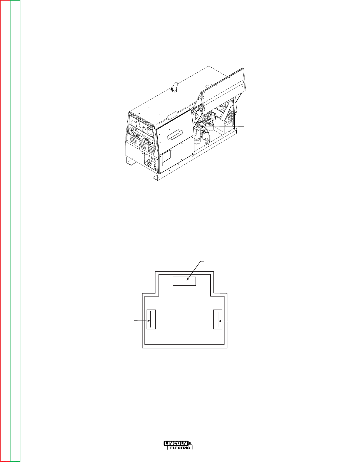
Return to Section TOC Return to Section TOC Return to Section TOC Return to Section TOC
Return to Master TOC Return to Master TOC Return to Master TOC Return to Master TOC
TEST PROCEDURE
1. Conduct this test with the engine off.
2. Unlatch and open the right side engine
access door.
3. Locate and disconnect plug J12. See
Figure F.3. Also see the Wiring Diagram.
TROUBLESHOOTING & REPAIR
F-26 F-26
RANGER 300 D AND 300 DLX
FUEL SHUTDOWN SOLENOID RESISTANCE TEST (continued)
FIGURE F.3 – PLUG J12 LOCATION
FIGURE F.4 – PLUG J12 PIN/LEAD ASSIGNMENTS
LEAD #237
LEAD #224B
LEAD #5K
4. Using the ohmmeter, check the resistance
from lead #237 to lead #5K. See Figure F.4.
Normal resistance of the “pull-in” coil is
approximately 0.5 ohms.
5. Using the ohmmeter, check the resistance
from lead #224B to lead #5K. See Figure
F.4. Normal resistance of the “hold-in” coil
is approximately 11.5 ohms.
NOTE: This solenoid is activated with 12VDC.
The “hold-in” voltage is derived from the control board. The “pull-in” voltage is derived
from the starter contactor. See the Wiring
Diagram. If the 12VDC is not present, check
the leads and associated connections.
6. Reassemble plug J12 and close and latch
the engine access door.
PLUG J12
LOCATION
Page 86

Return to Section TOC Return to Section TOC Return to Section TOC Return to Section TOC
Return to Master TOC Return to Master TOC Return to Master TOC Return to Master TOC
TROUBLESHOOTING & REPAIR
F-27 F-27
RANGER 300 D AND 300 DLX
WARNING
HIGH SPEED SOLENOID TEST
Service and repair should be performed by only Lincoln Electric factory trained personnel.
Unauthorized repairs performed on this equipment may result in danger to the technician or
machine operator and will invalidate your factory warranty. For your safety and to avoid electrical shock, please observe all safety notes and precautions detailed throughout this manual.
If for any reason you do not understand the test procedures or are unable to perform the
test/repairs safely, contact the Lincoln Electric Service Department for electrical troubleshooting assistance before you proceed. Call 1-800-833-9353 (WELD).
TEST DESCRIPTION
This test will determine if the solenoid coil resistance is normal and also if the solenoid is
capable of functioning when it is energized with 12VDC.
MATERIALS NEEDED
External 12VDC supply (30 amps)
Wiring Diagram
Volt/Ohmmeter
This procedure requires approximately 35 minutes to perform.
Page 87

Return to Section TOC Return to Section TOC Return to Section TOC Return to Section TOC
Return to Master TOC Return to Master TOC Return to Master TOC Return to Master TOC
TROUBLESHOOTING & REPAIR
F-28 F-28
RANGER 300 D AND 300 DLX
HIGH SPEED SOLENOID TEST (continued)
FIGURE F.5 – SOLENOID LEADS
PULL-IN COIL
(LARGER TERMINALS
TOP AND BOTTOM
#222H AND #213A)
HOLD-IN COIL
(SMALLER TERMINALS
TOP AND BOTTOM
#222J AND #214A)
TEST PROCEDURE
1. Turn the engine off.
2. Unlatch, lift and secure the right side engine
service access door.
3. Locate and remove the four spade connectors that attach the solenoid terminals to the
wiring harness leads (#222J, #222H, #213A
and #214A). See Figure F.5 and the Wiring
Diagram. Remove any necessary wire
wraps.
4. Check the pull-in coil resistance (larger terminals #222H and #213A). The normal
resistance is approximately 0.4 ohms.
Check the hold-in coil resistance (smaller
terminals #222J and #214A). The normal
resistance is approximately 20 ohms).
If either coil resistance is not correct, the
solenoid may be faulty. Replace.
5. Using the external 12VDC supply, apply
12VDC to the larger solenoid terminals
(#222H+ to #213A-). The solenoid should
activate. The solenoid should deactivate
when the 12VDC is removed.
When the solenoid activates, remove the voltage immediately. Do not leave the external
supply connected to terminals #222H and
#213A for longer than three seconds.
Component damage could result.
8. If the solenoid does not operate properly,
check for a mechanical restriction in the
linkage.
9. Using the external 12VDC supply, apply
12VDC to the smaller solenoid terminals
for the hold-in coil (#222J+ to #214A-).
Push in the solenoid plunger. With the
12VDC applied to the hold-in coil, the
plunger should stay in until the 12VDC is
removed.
10. If the linkage is intact and the solenoid
does not operate correctly when the
12VDC is applied, the solenoid may be
faulty. Replace.
11. Replace the harness leads to the correct
terminals. See Figure F.5 and the Wiring
Diagram. Replace any previously removed wire wraps.
12. Close and secure the right side engine
service access door.
CAUTION
Page 88

Return to Section TOC Return to Section TOC Return to Section TOC Return to Section TOC
Return to Master TOC Return to Master TOC Return to Master TOC Return to Master TOC
TROUBLESHOOTING & REPAIR
F-29 F-29
RANGER 300 D AND 300 DLX
WARNING
ENGINE THROTTLE ADJUSTMENT TEST
Service and repair should be performed by only Lincoln Electric factory trained personnel.
Unauthorized repairs performed on this equipment may result in danger to the technician or
machine operator and will invalidate your factory warranty. For your safety and to avoid electrical shock, please observe all safety notes and precautions detailed throughout this manual.
If for any reason you do not understand the test procedures or are unable to perform the
test/repairs safely, contact the Lincoln Electric Service Department for electrical troubleshooting assistance before you proceed. Call 1-800-833-9353 (WELD).
TEST DESCRIPTION
If the machine output is low or high, this test will determine whether the engine is operating
at the correct speed (RPM) during both HIGH and LOW idle conditions. Directions for adjusting the throttle to the correct RPM are given.
MATERIALS NEEDED
5/16” Nut driver
3/8” Nut driver
10mm Wrench
7/16” Wrench
White or red marking pencil
Strobe-tach, frequency counter, or oscilloscope
This procedure requires approximately 30 minutes to perform.
Page 89

TROUBLESHOOTING & REPAIR
F-30 F-30
RANGER 300 D AND 300 DLX
Return to Section TOC Return to Section TOC Return to Section TOC Return to Section TOC
Return to Master TOC Return to Master TOC Return to Master TOC Return to Master TOC
ENGINE THROTTLE ADJUSTMENT TEST (continued)
FIGURE F.6 – STROBE MARK LOCATION
TEST PROCEDURE
1. Conduct this procedure with the engine
OFF.
2. Unlatch, lift, and secure the right side service access door. With the 3/8” nut driver,
remove the right front side cover.
3. With a white or red marking pencil, place a
mark on one of the flywheel bolts. See
Figure F.6 for location.
4. Connect the strobe-tach according to the
manufacturer’s instructions.
5. Start the engine and direct the strobe-tach
light on the flywheel bolt. Synchronize it to
the rotating mark.
With the machine at HIGH IDLE the tach
should read between 3650 and 3700 RPM.
With the machine at LOW IDLE the tach
should read between 2150 and 2220 RPM.
FLYWHEEL
CHALK MARK
Page 90

Return to Section TOC Return to Section TOC Return to Section TOC Return to Section TOC
Return to Master TOC Return to Master TOC Return to Master TOC Return to Master TOC
TROUBLESHOOTING & REPAIR
F-31 F-31
RANGER 300 D AND 300 DLX
ENGINE THROTTLE ADJUSTMENT TEST (continued)
FIGURE F.7 – HIGH IDLE ADJUSTMENT
FIGURE F.8 – LOW IDLE ADJUSTMENT
SOLENOID LINKAGE
LOW SPEED SET
SCREW AND
LOCKING NUT
LOCKING NUT
Page 91

Return to Section TOC Return to Section TOC Return to Section TOC Return to Section TOC
Return to Master TOC Return to Master TOC Return to Master TOC Return to Master TOC
TROUBLESHOOTING & REPAIR
F-32 F-32
RANGER 300 D AND 300 DLX
ENGINE THROTTLE ADJUSTMENT TEST (continued)
6. If either of the readings is incorrect, adjust
the throttle as follows:
Adjust HIGH IDLE: First make sure there is
NOT a load on the machine. Set the IDLER
switch to the HIGH position. The solenoid
should activate. Using the 7/16” wrench,
adjust the high speed solenoid linkage to
lengthen the linkage until the engine speed
starts to decrease. See Figure F.7. Adjust
the linkage in the opposite direction until
the engine speed is within limits (3650 3700 RPM). Tighten the locking nut. The
high speed set screw is preset and sealed
by the engine manufacturer and normally
should not be adjusted.
Adjust LOW IDLE: First make sure there is
NOT a load on the machine. Set the IDLER
switch to AUTO and wait for the engine to
change to low idle speed. Use the 10mm
wrench to loosen the lock nut on the low
speed set screw. See Figure F.8. Adjust
the set screw until the engine speed is
between 2150 and 2220 RPM. Tighten the
lock nut.
Fr
equency Counter Method
1. Plug the frequency counter into one of the
115 VAC receptacles.
2. Start the engine and check the frequency
counter. At HIGH IDLE (3700 RPM), the
counter should read 63 Hz. At LOW IDLE
(2220 RPM), the counter should read 37 Hz.
Note that these are median measurements;
Hertz readings may vary slightly above or
below.
3. If either of the readings is incorrect, adjust
the throttle as follows:
Adjust HIGH IDLE: First make sure there is
NOT a load on the machine. Set the IDLER
switch to the HIGH position. The solenoid
should activate. Using the 7/16” wrench,
adjust the high speed solenoid linkage to
lengthen the linkage until the engine speed
starts to decrease. See Figure F.7. Adjust
the linkage in the opposite direction until
the frequency is 63 Hz. Tighten the locking
nut. The high speed set screw is preset and
sealed by the engine manufacturer and normally should not be adjusted.
Adjust LOW IDLE: First make sure there is
NOT a load on the machine. Set the IDLER
switch to AUTO and wait for the engine to
change to low idle speed. Use the 10mm
wrench to loosen the lock nut on the low
speed set screw. See Figure F.8. Adjust
the set screw until the frequency is 37 Hz.
Tighten the lock nut.
Oscilloscope Method
1. Connect the oscilloscope to the 115 VAC
receptacle, according to the manufacturer’s
instructions. At HIGH IDLE (3700 RPM), the
waveform should exhibit a period of 15.8
milliseconds. At LOW IDLE (2220 RPM), the
waveform should exhibit a period of 27.02
milliseconds. Refer to the NORMAL OPEN
CIRCUIT VOLTAGE WAVEFORM (115VAC
SUPPLY) HIGH IDLE - NO LOAD in this
section of the manual.
2. If either of these waveform periods is incorrect, adjust the throttle as follows:
Adjust HIGH IDLE: First make sure there is
NOT a load on the machine. Set the IDLER
switch to the HIGH position. The solenoid
should activate. Using the 7/16” wrench,
adjust the high speed solenoid linkage to
lengthen the linkage until the engine speed
starts to decrease. See Figure F.7. Adjust
the linkage in the opposite direction until
the period is 15.8 milliseconds. Tighten the
locking nut. The high speed set screw is
preset and sealed by the engine manufacturer and normally should not be adjusted.
Adjust LOW IDLE: First make sure there is
NOT a load on the machine. Set the IDLER
switch to AUTO and wait for the engine to
change to low idle speed. Use the 10mm
wrench to loosen the lock nut on the low
speed set screw. See Figure F.8. Adjust
the set screw until the period is 27.02 milliseconds. Tighten the lock nut.
Page 92

Return to Section TOC Return to Section TOC Return to Section TOC Return to Section TOC
Return to Master TOC Return to Master TOC Return to Master TOC Return to Master TOC
TROUBLESHOOTING & REPAIR
F-33 F-33
RANGER 300 D AND 300 DLX
WARNING
AUXILIARY AND FIELD WINDING TEST
Service and repair should be performed by only Lincoln Electric factory trained personnel.
Unauthorized repairs performed on this equipment may result in danger to the technician or
machine operator and will invalidate your factory warranty. For your safety and to avoid electrical shock, please observe all safety notes and precautions detailed throughout this manual.
If for any reason you do not understand the test procedures or are unable to perform the
test/repairs safely, contact the Lincoln Electric Service Department for electrical troubleshooting assistance before you proceed. Call 1-800-833-9353 (WELD).
TEST DESCRIPTION
This test will determine if the correct AC voltages are being generated from the stator windings.
MATERIALS NEEDED
Volt/Ohmmeter
5/16” Nut driver
3/8” Nut driver
Wiring Diagram
This procedure requires approximately 45 minutes to perform.
Page 93

Return to Section TOC Return to Section TOC Return to Section TOC Return to Section TOC
Return to Master TOC Return to Master TOC Return to Master TOC Return to Master TOC
TROUBLESHOOTING & REPAIR
F-34 F-34
RANGER 300 D AND 300 DLX
AUXILIARY AND FIELD WINDING TEST (continued)
FIGURE F.9 – LOCATION OF LEADS #3A AND #3B
TEST PROCEDURE
To test the 115 VAC winding:
1. With the 5/16” and 3/8” nut drivers, remove
the case left side.
2. Make sure that the LOCAL/REMOTE switch
(S8) is in the CONTROL AT WELDER position.
3. Set the voltmeter to the AC volts position.
4. Connect the volt/ohmmeter probes to leads
#3A and #3B where they connect to the 15
amp circuit breakers. See Figure F.9.
5. Start the engine and run it at high idle (3700
RPM).
6. Set the output control to the maximum
position (position 10).
7. Check the AC voltage reading. It should be
approximately 125 VAC.
To test the 230 VAC winding:
1. With the 5/16” and 3/8” nut drivers, remove
the case left side.
2. Set the voltmeter to the AC volts position.
3. Connect the volt/ohmmeter probes to leads
#6 and #3 where they connect to the 50
amp circuit breakers. See the Wiring
Diagram.
NOTE: It is easier to insert the probes directly
into the receptacle to perform this test.
However, the probes may not reach in far
enough to make or keep a good connection.
4. Start the engine and run it at high idle (3700
RPM).
5. Set the output control to the maximum
position (position 10).
6. Check the AC voltage reading. It should be
approximately 240 VAC.
15 AMP
CB LEADS
#3A AND #3B
LOCATED ON
REAR OF PANEL
Page 94
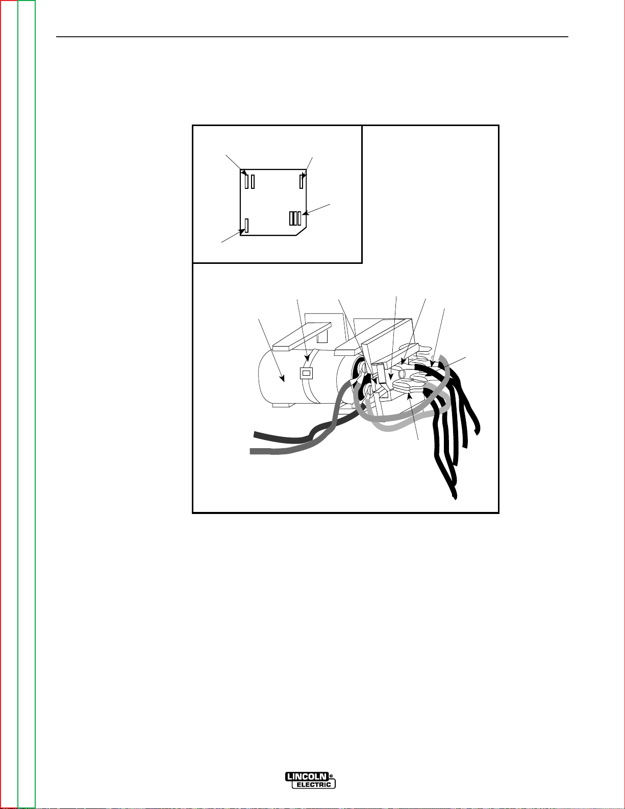
Return to Section TOC Return to Section TOC Return to Section TOC Return to Section TOC
Return to Master TOC Return to Master TOC Return to Master TOC Return to Master TOC
TROUBLESHOOTING & REPAIR
F-35 F-35
RANGER 300 D AND 300 DLX
AUXILIARY AND FIELD WINDING TEST (continued)
FIGURE F.10 – LOCATION OF LEADS #7 AND #9 AT FIELD BRIDGE RECTIFIER
200
200A
200B
201
201A
200
200A
200B
7
9
+
_
AC
AC
7
201
201A
9
Field
Bridge
Rectifier
Retaining
Tab
Cable
Tie
Capacitor
To test the field winding:
1. With the 5/16” and 3/8” nut drivers, remove
the case right side.
2. Connect the volt/ohmmeter probes to leads
#7 and #9 where they connect to the Field
Bridge Rectifier. See Figure F.10.
3. Start the engine and run it at high idle (3700
RPM).
4. Set the output control to the maximum
position (position 10).
5. Check the AC voltage reading. It should be
between 40 and 47 VAC.
If the reading is missing or not within specifications, check for loose or broken wires
between the test points and the stator
windings. See the Wiring Diagram. Make
sure that the windings are NOT grounded
internally to the stator iron. If the leads are
intact, then the stator may be faulty. Replace the stator. If the voltage reading is
within specifications, the windings are good
and functioning properly.
6. Reinstall the right case side.
Page 95

Return to Section TOC Return to Section TOC Return to Section TOC Return to Section TOC
Return to Master TOC Return to Master TOC Return to Master TOC Return to Master TOC
TROUBLESHOOTING & REPAIR
F-36 F-36
RANGER 300 D AND 300 DLX
AUXILIARY AND FIELD WINDING TEST (continued)
FIGURE F.11 – 14-PIN AMPHENOL PIN ASSIGNMENTS
To test the feeder winding:
Ranger 300 DLX Models
1. With the 5/16” and 3/8” nut drivers, remove
the case left side.
2. Set the voltmeter to the AC volts position.
3. Connect the volt/ohmmeter probes to leads
#31 and #32 where they connect to 15 amp
circuit breaker CB1 and the 14-pin amphenol. See the Wiring Diagram. See Figure
F.11.
NOTE: It is possible to check this voltage reading at the amphenol by inserting the test
probes at pin A (for lead #32) and pin J (for lead
#31A). See Figure F.11. However, if you use
this method and get no voltage reading, it
could mean there is a break or loose connection in the leads between the circuit breaker
and the amphenol. Check the reading again
with one probe at the circuit breaker connection for lead #31 and the other probe at amphenol pin A.
4. Start the engine and run it at high idle (3700
RPM).
5. Set the output control to the maximum
position (position 10).
6. Check the AC voltage reading. It should be
between 115 and 126 VAC.
7. Connect the volt/ohmmeter probes to
leads #31 and #42 where they connect to
15 amp circuit breaker CB1 and the 14-pin
amphenol. See the Wiring Diagram.
NOTE: It is possible to check this voltage reading at the amphenol by inserting the test
probes at pin K (for lead #42) and pin I (for lead
#31B). See Figure F.11. However, if you use
this method and get no voltage reading, it
could mean there is a break or loose connection in the leads between the circuit breaker
and the amphenol. Check the reading again
with one probe at the circuit breaker connection for lead #31 and the other probe at amphenol pin K.
8. Set the output control to the maximum
position (position 10).
9. Check the AC voltage reading. It should
be between 43 and 50 VAC.
If the voltage readings are within specifications,
then the windings are good and functioning
properly.
If any one or more of the readings are missing or
not within specifications, check for loose or broken wires between the test points and the stator
windings. See the Wiring Diagram. Make sure
that the windings are NOT grounded internally to
the stator iron. If the leads are intact, then the
stator may be faulty. Replace the stator.
10. Reinstall the right case side.
K
B
I
H
N
L
C
D
M
G
E
F
J
A
Page 96

Return to Section TOC Return to Section TOC Return to Section TOC Return to Section TOC
Return to Master TOC Return to Master TOC Return to Master TOC Return to Master TOC
TROUBLESHOOTING & REPAIR
F-37 F-37
RANGER 300 D AND 300 DLX
WARNING
ROTOR VOLTAGE TEST
Service and repair should be performed by only Lincoln Electric factory trained personnel.
Unauthorized repairs performed on this equipment may result in danger to the technician or
machine operator and will invalidate your factory warranty. For your safety and to avoid electrical shock, please observe all safety notes and precautions detailed throughout this manual.
If for any reason you do not understand the test procedures or are unable to perform the
test/repairs safely, contact the Lincoln Electric Service Department for electrical troubleshooting assistance before you proceed. Call 1-800-833-9353 (WELD).
TEST DESCRIPTION
This test will determine if the correct DC voltage is being applied to the rotor at maximum
engine speed (3700 RPM - high idle). This information will aid the technician in determining
if the generator field is operating properly.
MATERIALS NEEDED
Volt/Ohmmeter (Multimeter)
5/16” Nut driver
3/8” Nut driver
Wiring Diagram
This procedure requires approximately 20 minutes to perform.
Page 97
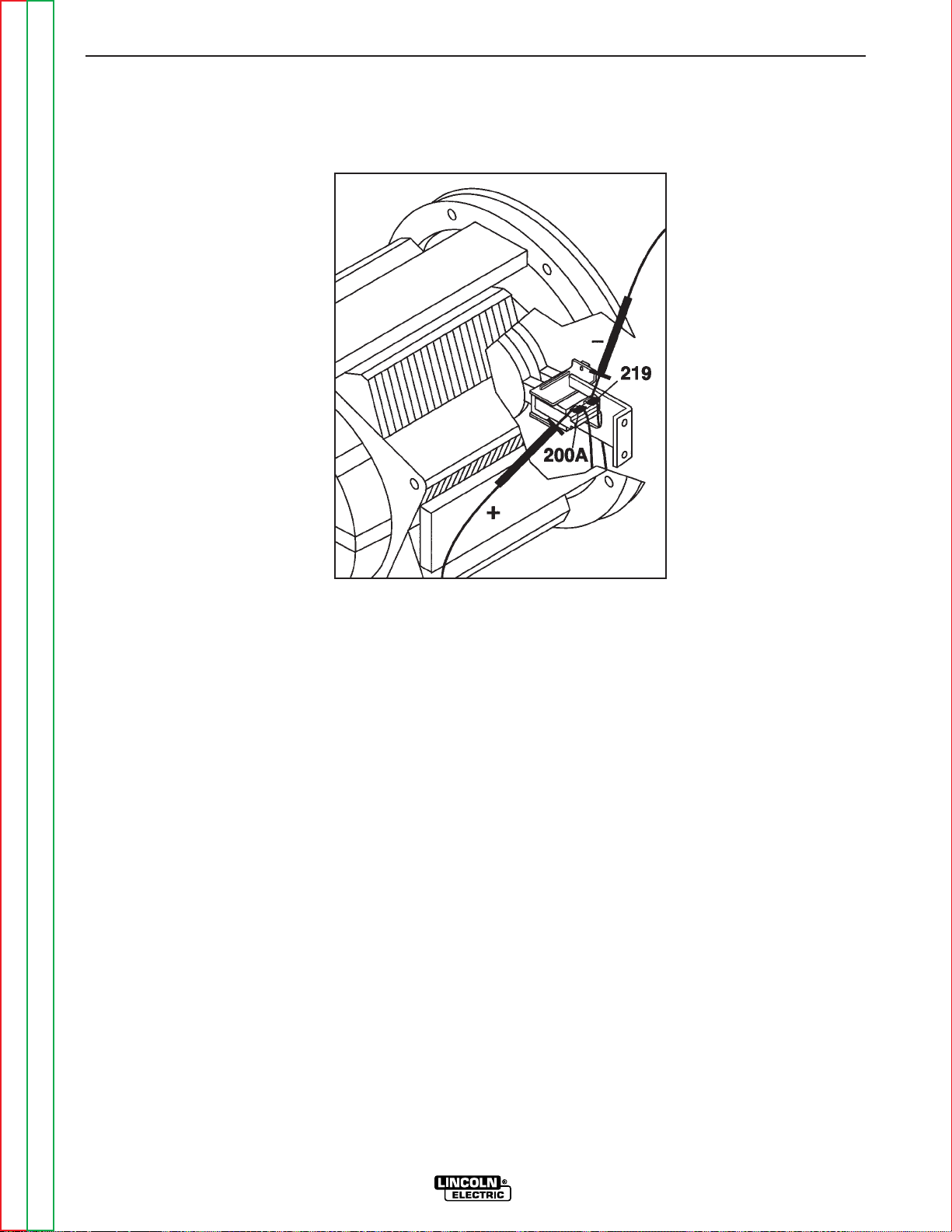
Return to Section TOC Return to Section TOC Return to Section TOC Return to Section TOC
Return to Master TOC Return to Master TOC Return to Master TOC Return to Master TOC
TROUBLESHOOTING & REPAIR
F-38 F-38
RANGER 300 D AND 300 DLX
ROTOR VOLTAGE TEST (continued)
FIGURE F.12 – LOCATION OF LEADS 200A AND 219 FOR ROTOR VOLTAGE TEST
TEST PROCEDURE
1. With the 5/16” and 3/8” nut drivers, remove
the right case side.
2. Set the volt/ohmmeter to the DC volts position.
3. Connect the positive meter probe to the
brush nearest the rotor lamination (lead
#200A). See Figure F.12 for location.
4. Connect the negative meter probe to the
other brush (lead #219).
5. Set the LOCAL/REMOTE switch (S8) to the
CONTROL AT WELDER position. Start the
engine and run it at high idle (3700 RPM).
Set the output control to the MAXIMUM
position (position 10).
6. Check the voltage reading on the voltmeter.
It should read approximately 37-40 VDC.
7. If the voltage reading is low or not present,
the generator field is not functioning properly. Perform the Rotor Resistance Test.
The Field Diode Bridge (D2), the Field
Capacitor (C1), and/or the control board
may be faulty.
8. If the voltage reading is normal, the field circuit is functioning properly. Install the right
case side.
Page 98

Return to Section TOC Return to Section TOC Return to Section TOC Return to Section TOC
Return to Master TOC Return to Master TOC Return to Master TOC Return to Master TOC
INSTALLATION
F-39 F-39
RANGER 300 D AND 300 DLX
WARNING
CHARGING CIRCUIT TEST
Service and repair should be performed by only Lincoln Electric factory trained personnel.
Unauthorized repairs performed on this equipment may result in danger to the technician or
machine operator and will invalidate your factory warranty. For your safety and to avoid electrical shock, please observe all safety notes and precautions detailed throughout this manual.
If for any reason you do not understand the test procedures or are unable to perform the
test/repairs safely, contact the Lincoln Electric Service Department for electrical troubleshooting assistance before you proceed. Call 1-800-833-9353 (WELD).
TEST DESCRIPTION
This test will determine if the engine alternator and associated circuitry are functioning properly.
MATERIALS NEEDED
Volt/Ohmmeter
5/16” Nut driver
3/8” Nut driver
Wiring Diagram
This procedure requires approximately 20 minutes to perform.
Page 99

Return to Section TOC Return to Section TOC Return to Section TOC Return to Section TOC
Return to Master TOC Return to Master TOC Return to Master TOC Return to Master TOC
INSTALLATION
F-40 F-40
RANGER 300 D AND 300 DLX
CHARGING CIRCUIT TEST (continued)
FIGURE F.13 – VOLTAGE REGULATOR LEADS
TEST PROCEDURE
1. With the 5/16” and 3/8” nut drivers, remove
the right case side.
2. Locate the engine alternator and leads. See
Figure F.13.
3. Set the voltmeter for DC volts and check for
the typical DC voltages according to the
Charging Circuit Test Chart below.
4. If the DC voltages are correct, the engine
alternator is operating normally.
If any of the voltage readings are missing or
not normal, the engine alternator or associated wiring may be faulty. See the Wiring
Diagram.
CHARGING CIRCUIT TEST CHART
TEST CONDITIONS TEST POINTS TYPICAL VOLTAGE
Ignition Switch Off Lead 222D to Frame Ground 12 VDC
Ignition Switch Off Lead 224A to Frame Ground 0 VDC
Ignition Switch Off Lead 227 to Frame Ground 0 VDC
Ignition Switch On Lead 222D to Frame Ground 12 VDC
Ignition Switch On Lead 224A to Frame Ground 12 VDC
Ignition Switch On Lead 227 to Frame Ground 0.7 VDC
Engine running at 3700 RPM Lead 222D to Frame Ground 14.5 VDC
Engine running at 3700 RPM Lead 224A to Frame Ground 14.3 VDC
Engine running at 3700 RPM Lead 227 to Frame Ground 14.3 VDC
B
IG
L
222D
224A
ALTERNATOR
227
Page 100
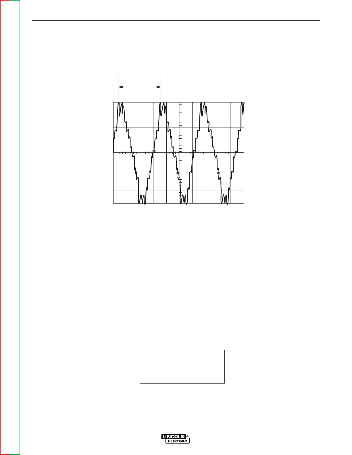
Return to Section TOC Return to Section TOC Return to Section TOC Return to Section TOC
Return to Master TOC Return to Master TOC Return to Master TOC Return to Master TOC
TROUBLESHOOTING & REPAIR
F-41 F-41
RANGER 300 D AND 300 DLX
This is the typical auxiliary output
voltage generated from a properly
operating machine. Note that each
vertical division represents 50 volts
and that each horizontal division represents 5 milliseconds in time.
Note: Scope probes connected at
machine 115VAC receptacle.
SCOPE SETTINGS
Volts/Div.....................50V/Div.
Horizontal Sweep.....5 ms/Div.
Coupling ............................DC
Trigger .........................Internal
NORMAL OPEN CIRCUIT VOLTAGE WAVEFORM (115VAC SUPPLY)
HIGH IDLE – NO LOAD – OUTPUT CONTROL AT MAXIMUM
0 volts
5 ms
50 volts
15.8 ms
 Loading...