

Page 1
SVM141-A
November, 1998
Safety Depends on You
Lincoln arc welding and cutting
equipment is designed and built
with safety in mind. However,
your overall safety can be increased by proper installation . . .
and thoughtful operation on
your part. DO NOT INSTALL,
OPERATE OR REPAIR THIS
EQUIPMENT WITHOUT
READING THIS MANUAL AND
THE SAFETY PRECAUTIONS
CONTAINED THROUGHOUT.
And, most importantly, think
before you act and be careful.
SERVICE MANUAL
For use with machine code numbers: 10523 & 10525
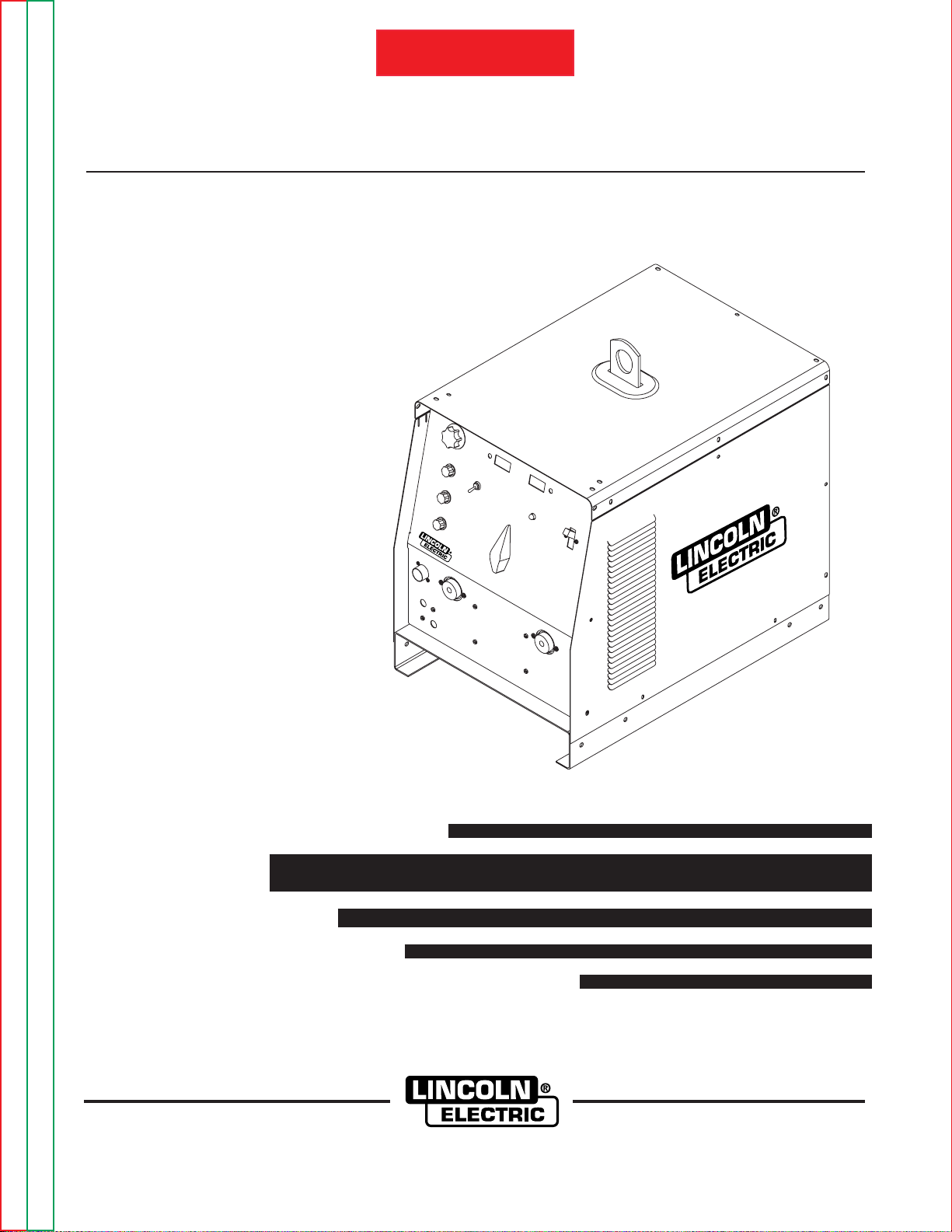
Square Wave TIG 275
Return to Master TOC Return to Master TOC Return to Master TOC Return to Master TOC
View Safety Info View Safety Info View Safety Info View Safety Info
RETURN TO MAIN INDEX
• Sales and Service through Subsidiaries and Distributors Worldwide •
Cleveland, Ohio 44117-1199 U.S.A. TEL: 216.481.8100 FAX: 216.486.1751 WEB SITE: www.lincolnelectric.com
World's Leader in Welding and Cutting Products Premier Manufacturer of Industrial Motors
SQUARE WAVE TIG 275
Page 2
SAFETY
i i
SQUARE WAVE TIG 275
FOR ENGINE
powered equipment.
1.a. Turn the engine off before troubleshooting and maintenance
work unless the maintenance work requires it to be running.
____________________________________________________
1.b.Operate engines in open, well-ventilated
areas or vent the engine exhaust fumes
outdoors.
____________________________________________________
1.c. Do not add the fuel near an open flame weld-
ing arc or when the engine is running. Stop
the engine and allow it to cool before refueling to prevent spilled fuel from vaporizing on
contact with hot engine parts and igniting. Do
not spill fuel when filling tank. If fuel is spilled,
wipe it up and do not start engine until fumes
have been eliminated.
____________________________________________________
1.d. Keep all equipment safety guards, covers
and devices in position and in good
repair.Keep hands, hair, clothing and tools
away from V-belts, gears, fans and all other
moving parts when starting, operating or
repairing equipment.
____________________________________________________
1.e. In some cases it may be necessary to remove safety
guards to perform required maintenance. Remove
guards only when necessary and replace them when the
maintenance requiring their removal is complete.
Always use the greatest care when working near moving
parts.
___________________________________________________
1.f. Do not put your hands near the engine fan. Do not attempt to
override the governor or idler by pushing on the throttle control rods while the engine is running.
___________________________________________________
1.g. To prevent accidentally starting gasoline engines while
turning the engine or welding generator during maintenance
work, disconnect the spark plug wires, distributor cap or
magneto wire as appropriate.
ARC WELDING CAN BE HAZARDOUS. PROTECT YOURSELF AND OTHERS FROM POSSIBLE SERIOUS INJURY OR DEATH.
KEEP CHILDREN AWAY. PACEMAKER WEARERS SHOULD CONSULT WITH THEIR DOCTOR BEFORE OPERATING.
Read and understand the following safety highlights. For additional safety information, it is strongly recommended that you
purchase a copy of “Safety in Welding & Cutting - ANSI Standard Z49.1” from the American Welding Society , P.O. Box 351040,
Miami, Florida 33135 or CSA Standard W117.2-1974. A Free copy of “Arc Welding Safety” booklet E205 is available from the
Lincoln Electric Company, 22801 St. Clair Avenue, Cleveland, Ohio 44117-1199.
BE SURE THAT ALL INSTALLATION, OPERATION, MAINTENANCE AND REPAIR PROCEDURES ARE
PERFORMED ONLY BY QUALIFIED INDIVIDUALS.
WARNING
Mar ‘95
ELECTRIC AND
MAGNETIC FIELDS
may be dangerous
2.a. Electric current flowing through any conductor causes
localized Electric and Magnetic Fields (EMF). Welding
current creates EMF fields around welding cables and
welding machines
2.b. EMF fields may interfere with some pacemakers, and
welders having a pacemaker should consult their physician
before welding.
2.c. Exposure to EMF fields in welding may have other health
effects which are now not known.
2.d. All welders should use the following procedures in order to
minimize exposure to EMF fields from the welding circuit:
2.d.1.
Route the electrode and work cables together - Secure
them with tape when possible.
2.d.2. Never coil the electrode lead around your body.
2.d.3. Do not place your body between the electrode and
work cables. If the electrode cable is on your right
side, the work cable should also be on your right side.
2.d.4. Connect the work cable to the workpiece as close as
possible to the area being welded.
2.d.5. Do not work next to welding power source.
1.h. To avoid scalding, do not remove the
radiator pressure cap when the engine is
hot.
CALIFORNIA PROPOSITION 65 WARNINGS
Diesel engine exhaust and some of its constituents
are known to the State of California to cause cancer, birth defects, and other reproductive harm.
The engine exhaust from this product contains
chemicals known to the State of California to cause
cancer, birth defects, or other reproductive harm.
The Above For Diesel Engines
The Above For Gasoline Engines
Return to Master TOC Return to Master TOC Return to Master TOC Return to Master TOC
Page 3
SAFETY
ii ii
SQUARE WAVE TIG 275
ARC RAYS can burn.
4.a. Use a shield with the proper filter and cover
plates to protect your eyes from sparks and
the rays of the arc when welding or observing
open arc welding. Headshield and filter lens
should conform to ANSI Z87. I standards.
4.b. Use suitable clothing made from durable flame-resistant
material to protect your skin and that of your helpers from
the arc rays.
4.c. Protect other nearby personnel with suitable, non-flammable
screening and/or warn them not to watch the arc nor expose
themselves to the arc rays or to hot spatter or metal.
ELECTRIC SHOCK can kill.
3.a. The electrode and work (or ground) circuits
are electrically “hot” when the welder is on.
Do not touch these “hot” parts with your bare
skin or wet clothing. Wear dry, hole-free
gloves to insulate hands.
3.b. Insulate yourself from work and ground using dry insulation.
Make certain the insulation is large enough to cover your full
area of physical contact with work and ground.
In addition to the normal safety precautions, if welding
must be performed under electrically hazardous
conditions (in damp locations or while wearing wet
clothing; on metal structures such as floors, gratings or
scaffolds; when in cramped positions such as sitting,
kneeling or lying, if there is a high risk of unavoidable or
accidental contact with the workpiece or ground) use
the following equipment:
• Semiautomatic DC Constant Voltage (Wire) Welder.
• DC Manual (Stick) Welder.
• AC Welder with Reduced Voltage Control.
3.c. In semiautomatic or automatic wire welding, the electrode,
electrode reel, welding head, nozzle or semiautomatic
welding gun are also electrically “hot”.
3.d. Always be sure the work cable makes a good electrical
connection with the metal being welded. The connection
should be as close as possible to the area being welded.
3.e. Ground the work or metal to be welded to a good electrical
(earth) ground.
3.f.
Maintain the electrode holder, work clamp, welding cable and
welding machine in good, safe operating condition. Replace
damaged insulation.
3.g. Never dip the electrode in water for cooling.
3.h. Never simultaneously touch electrically “hot” parts of
electrode holders connected to two welders because voltage
between the two can be the total of the open circuit voltage
of both welders.
3.i. When working above floor level, use a safety belt to protect
yourself from a fall should you get a shock.
3.j. Also see Items 6.c. and 8.
FUMES AND GASES
can be dangerous.
5.a.Welding may produce fumes and gases
hazardous to health. Avoid breathing these
fumes and gases.When welding, keep
your head out of the fume. Use enough
ventilation and/or exhaust at the arc to keep
fumes and gases away from the breathing zone. When
welding with electrodes which require special
ventilation such as stainless or hard facing (see
instructions on container or MSDS) or on lead or
cadmium plated steel and other metals or coatings
which produce highly toxic fumes, keep exposure as
low as possible and below Threshold Limit Values (TLV)
using local exhaust or mechanical ventilation. In
confined spaces or in some circumstances, outdoors, a
respirator may be required. Additional precautions are
also required when welding on galvanized steel.
5.b.
Do not weld in locations near chlorinated hydrocarbon
vapors
coming from degreasing, cleaning or spraying operations.
The heat and rays of the arc can react with solvent vapors
to
form phosgene, a highly toxic gas, and other irritating
products.
5.c. Shielding gases used for arc welding can displace air and
cause injury or death. Always use enough ventilation,
especially in confined areas, to insure breathing air is safe.
5.d. Read and understand the manufacturer’s instructions for this
equipment and the consumables to be used, including the
material safety data sheet (MSDS) and follow your
employer’s safety practices. MSDS forms are available from
your welding distributor or from the manufacturer.
5.e. Also see item 1.b.
Mar ‘95
Return to Master TOC Return to Master TOC Return to Master TOC Return to Master TOC
Page 4
SQUARE WAVE TIG 275
FOR ELECTRICALLY
powered equipment.
8.a. Turn off input power using the disconnect
switch at the fuse box before working on
the equipment.
8.b. Install equipment in accordance with the U.S. National
Electrical Code, all local codes and the manufacturer’s
recommendations.
8.c. Ground the equipment in accordance with the U.S. National
Electrical Code and the manufacturer’s recommendations.
CYLINDER may explode
if damaged.
7.a. Use only compressed gas cylinders
containing the correct shielding gas for the
process used and properly operating
regulators designed for the gas and
pressure used. All hoses, fittings, etc. should be suitable for
the application and maintained in good condition.
7.b. Always keep cylinders in an upright position securely
chained to an undercarriage or fixed support.
7.c. Cylinders should be located:
•Away from areas where they may be struck or subjected to
physical damage.
•A safe distance from arc welding or cutting operations and
any other source of heat, sparks, or flame.
7.d. Never allow the electrode, electrode holder or any other
electrically “hot” parts to touch a cylinder.
7.e. Keep your head and face away from the cylinder valve outlet
when opening the cylinder valve.
7.f. Valve protection caps should always be in place and hand
tight except when the cylinder is in use or connected for
use.
7.g. Read and follow the instructions on compressed gas
cylinders, associated equipment, and CGA publication P-l,
“Precautions for Safe Handling of Compressed Gases in
Cylinders,” available from the Compressed Gas Association
1235 Jefferson Davis Highway, Arlington, VA 22202.
iii
SAFETY
iii
Mar ‘95
WELDING SPARKS can
cause fire or explosion.
6.a.
Remove fire hazards from the welding area.
If this is not possible, cover them to prevent
the welding sparks from starting a fire.
Remember that welding sparks and hot
materials from welding can easily go through small cracks
and openings to adjacent areas. Avoid welding near
hydraulic lines. Have a fire extinguisher readily available.
6.b. Where compressed gases are to be used at the job site,
special precautions should be used to prevent hazardous
situations. Refer to “Safety in Welding and Cutting” (ANSI
Standard Z49.1) and the operating information for the
equipment being used.
6.c. When not welding, make certain no part of the electrode
circuit is touching the work or ground. Accidental contact can
cause overheating and create a fire hazard.
6.d. Do not heat, cut or weld tanks, drums or containers until the
proper steps have been taken to insure that such procedures
will not cause flammable or toxic vapors from substances
inside. They can cause an explosion even
though
they have
been “cleaned”. For information, purchase “Recommended
Safe Practices for the
Preparation
for Welding and Cutting of
Containers and Piping That Have Held Hazardous
Substances”, AWS F4.1 from the American Welding Society
(see address above).
6.e. Vent hollow castings or containers before heating, cutting or
welding. They may explode.
6.f.
Sparks and spatter are thrown from the welding arc. Wear oil
free protective garments such as leather gloves, heavy shirt,
cuffless trousers, high shoes and a cap over your hair. Wear
ear plugs when welding out of position or in confined places.
Always wear safety glasses with side shields when in a
welding area.
6.g. Connect the work cable to the work as close to the welding
area as practical. Work cables connected to the building
framework or other locations away from the welding area
increase the possibility of the welding current passing
through lifting chains, crane cables or other alternate circuits.
This can create fire hazards or overheat lifting chains or
cables until they fail.
6.h. Also see item 1.c.
Return to Master TOC Return to Master TOC Return to Master TOC Return to Master TOC
Page 5

SAFETY
iv iv
SQUARE WAVE TIG 275
PRÉCAUTIONS DE SÛRETÉ
Pour votre propre protection lire et observer toutes les instructions
et les précautions de sûreté specifiques qui parraissent dans ce
manuel aussi bien que les précautions de sûreté générales suivantes:
Sûreté Pour Soudage A L’Arc
1. Protegez-vous contre la secousse électrique:
a. Les circuits à l’électrode et à la piéce sont sous tension
quand la machine à souder est en marche. Eviter toujours
tout contact entre les parties sous tension et la peau nue
ou les vétements mouillés. Porter des gants secs et sans
trous pour isoler les mains.
b. Faire trés attention de bien s’isoler de la masse quand on
soude dans des endroits humides, ou sur un plancher metallique ou des grilles metalliques, principalement dans
les positions assis ou couché pour lesquelles une grande
partie du corps peut être en contact avec la masse.
c. Maintenir le porte-électrode, la pince de masse, le câble de
soudage et la machine à souder en bon et sûr état defonctionnement.
d.Ne jamais plonger le porte-électrode dans l’eau pour le
refroidir.
e. Ne jamais toucher simultanément les parties sous tension
des porte-électrodes connectés à deux machines à souder parce que la tension entre les deux pinces peut être le
total de la tension à vide des deux machines.
f. Si on utilise la machine à souder comme une source de
courant pour soudage semi-automatique, ces precautions
pour le porte-électrode s’applicuent aussi au pistolet de
soudage.
2. Dans le cas de travail au dessus du niveau du sol, se protéger
contre les chutes dans le cas ou on recoit un choc. Ne jamais
enrouler le câble-électrode autour de n’importe quelle partie
du corps.
3. Un coup d’arc peut être plus sévère qu’un coup de soliel,
donc:
a. Utiliser un bon masque avec un verre filtrant approprié
ainsi qu’un verre blanc afin de se protéger les yeux du rayonnement de l’arc et des projections quand on soude ou
quand on regarde l’arc.
b. Porter des vêtements convenables afin de protéger la
peau de soudeur et des aides contre le rayonnement de
l‘arc.
c. Protéger l’autre personnel travaillant à proximité au
soudage à l’aide d’écrans appropriés et non-inflammables.
4. Des gouttes de laitier en fusion sont émises de l’arc de
soudage. Se protéger avec des vêtements de protection libres
de l’huile, tels que les gants en cuir, chemise épaisse, pantalons sans revers, et chaussures montantes.
5. Toujours porter des lunettes de sécurité dans la zone de
soudage. Utiliser des lunettes avec écrans lateraux dans les
zones où l’on pique le laitier.
6. Eloigner les matériaux inflammables ou les recouvrir afin de
prévenir tout risque d’incendie dû aux étincelles.
7. Quand on ne soud
e pas, poser la pince à une endroit isolé de
la masse. Un court-circuit accidental peut provoquer un
échauffement et un risque d’incendie.
8. S’assurer que la masse est connectée le plus prés possible de
la zone de travail qu’il est pratique de le faire. Si on place la
masse sur la charpente de la construction ou d’autres endroits
éloignés de la zone de travail, on augmente le risque de voir
passer le courant de soudage par les chaines de levage,
câbles de grue, ou autres circuits. Cela peut provoquer des
risques d’incendie ou d’echauffement des chaines et des
câbles jusqu’à ce qu’ils se rompent.
9. Assurer une ventilation suffisante dans la zone de soudage.
Ceci est particuliérement important pour le soudage de tôles
galvanisées plombées, ou cadmiées ou tout autre métal qui
produit des fumeés toxiques.
10. Ne pas souder en présence de vapeurs de chlore provenant
d’opérations de dégraissage, nettoyage ou pistolage. La
chaleur ou les rayons de l’arc peuvent réagir avec les vapeurs
du solvant pour produire du phosgéne (gas fortement toxique)
ou autres produits irritants.
11. Pour obtenir de plus amples renseignements sur la sûreté, voir
le code “Code for safety in welding and cutting” CSAStandard
W 117.2-1974.
PRÉCAUTIONS DE SÛRETÉ POUR
LES MACHINES À SOUDER À
TRANSFORMATEUR ET À
REDRESSEUR
1. Relier à la terre le chassis du poste conformement au code de
l’électricité et aux recommendations du fabricant. Le dispositif
de montage ou la piece à souder doit être branché à une
bonne mise à la terre.
2. Autant que possible, I’installation et l’entretien du poste seront
effectués par un électricien qualifié.
3. Avant de faires des travaux à l’interieur de poste, la debrancher à l’interrupteur à la boite de fusibles.
4. Garder tous les couvercles et dispositifs de sûreté à leur
place.
Mar. ‘93
Return to Master TOC Return to Master TOC Return to Master TOC Return to Master TOC
Page 6

MASTER TABLE OF CONTENTS FOR ALL SECTIONS
v v
SQUARE WAVE TIG 275
Page
Safety ...................................................................................................................................................................i-iv
Installation...............................................................................................................................................Section A
Technical Specifications...............................................................................................................................A-2
Safety Precautions.......................................................................................................................................A-3
Input Supply Connections............................................................................................................................A-4
Input Reconnect Procedure .........................................................................................................................A-5
User Supplied Connectors...........................................................................................................................A-6
Output Connections......................................................................................................................................A-6
Work Cable Connection ...............................................................................................................................A-6
TIG Torch Connection ..................................................................................................................................A-7
Twist-Mate Adapter for LA-9 and LA-17 TIG Torch ......................................................................................A-8
Twist-Mate Adapter for LW-18 and LW-20 TIG Torch...................................................................................A-8
Stick Electrode Cable Connection................................................................................................................A-9
Operation.................................................................................................................................................Section B
Safety Precautions.......................................................................................................................................B-2
General Description......................................................................................................................................B-3
Recommended Processes and Equipment..................................................................................................B-3
Design Features and Advantages................................................................................................................B-3
Welding Capability........................................................................................................................................B-4
Limitations ....................................................................................................................................................B-4
Controls and Settings ...................................................................................................................................B-5
Welding Operation........................................................................................................................................B-6
Stick Welding................................................................................................................................................B-9
Auxiliary Power.............................................................................................................................................B-9
Accessories ............................................................................................................................................Section C
Maintenance............................................................................................................................................Section D
Safety Precautions.......................................................................................................................................D-2
Routine and Periodic Maintenance..............................................................................................................D-2
Overload Protection .....................................................................................................................................D-2
Fan As Needed (F.A.N.) ...............................................................................................................................D-2
Service Procedures......................................................................................................................................D-2
Component Location and Access................................................................................................................D-3
Spark Gap Adjustment .................................................................................................................................D-3
Theory of Operation...............................................................................................................................Section E
General Description......................................................................................................................................E-2
Input Power Circuit .......................................................................................................................................E-2
Output Rectification, Control Board and Feedback......................................................................................E-3
High Voltage / High Frequency Circuit.........................................................................................................E-4
DC Welding Output ......................................................................................................................................E-5
AC Welding Output.......................................................................................................................................E-6
SCR Operation.............................................................................................................................................E-7
Protective Circuits ........................................................................................................................................E-8
Troubleshooting and Repair ..................................................................................................................Section F
How to Use Troubleshooting Guide.............................................................................................................F-2
PC Board Troubleshooting Procedures........................................................................................................F-3
Troubleshooting Guide.................................................................................................................................F-4
Test Procedures..........................................................................................................................................F-18
Oscilloscope Waveforms............................................................................................................................F-33
Replacement Procedures...........................................................................................................................F-42
Retest After Repair .....................................................................................................................................F-59
Electrical Diagrams ................................................................................................................................Section G
Parts Manual .......................................................................................................................................P316 Series
RETURN TO MAIN INDEX
Page 7

Section A-1 Section A-1
SQUARE WAVE TIG 275
TABLE OF CONTENTS
- INSTALLATION SECTION -
Installation .............................................................................................................................Section A
Technical Specifications, Square Wave TIG 275 (K1617-1) .......................................................A-2
Safety Precautions......................................................................................................................A-3
Select Suitable Location .....................................................................................................A-3
Stacking...............................................................................................................................A-3
Lifting and Moving...............................................................................................................A-3
Tilting ...................................................................................................................................A-3
Environmental Rating ..........................................................................................................A-3
Machine Grounding and High Frequency Interference Protection .....................................A-3
Input Supply Connections ..........................................................................................................A-4
Input Reconnect Procedure........................................................................................................A-5
User Supplied Connectors .........................................................................................................A-6
Output Connections....................................................................................................................A-6
Work Cable Connection..............................................................................................................A-6
TIG Torch Connection.................................................................................................................A-7
Twist-Mate Adapter for LA-9 and LA-17 TIG Torch....................................................................A-8
Twist-Mate Adapter for LW-18 and LW-20 TIG Torch................................................................A-8
Stick Electrode Cable Connection..............................................................................................A-9
Return to Master TOC Return to Master TOC Return to Master TOC Return to Master TOC
Page 8
Return to Section TOC Return to Section TOC Return to Section TOC Return to Section TOC
Return to Master TOC Return to Master TOC Return to Master TOC Return to Master TOC
INSTALLATION
A-2 A-2
SQUARE WAVE TIG 275
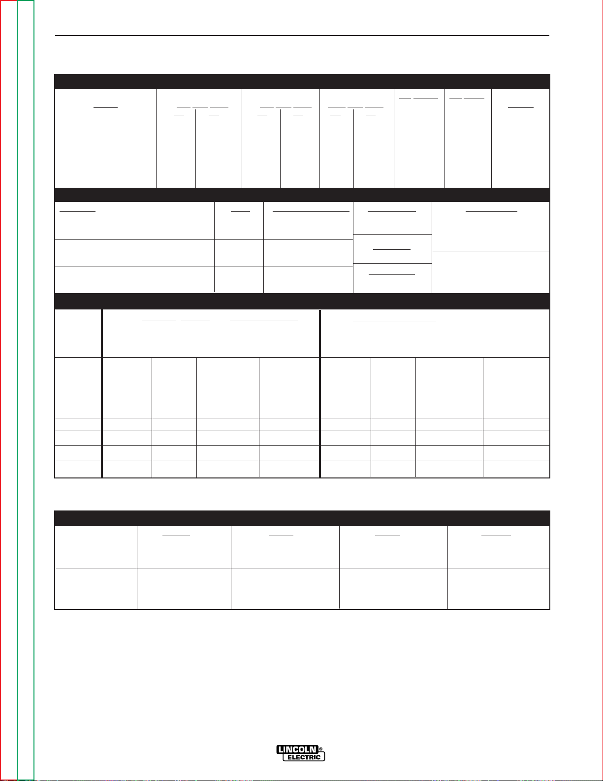
TECHNICAL SPECIFICATIONS - Square Wave TIG 275
For all Stick, DC TIG and Balanced AC TIG
Welding at 275A 40% Duty Cycle
w/o Optional K1620-1 Power Factor Capacitors
Based on the 1996 U.S. National Electrical Code
For Unbalanced AC TIG Welding above 180A,
255A 40% Duty Cycle, Maximum Penetration
w/o Optional K1620-1 Power Factor Capacitors
Based on the 1996 U.S. National Electrical Code
INPUT - SINGLE PHASE ONLY
RECOMMENDED INPUT WIRE AND FUSE SIZES
Input
Voltage /
phase/
Frequency
208/1/60
230/1/60
460/1/60
575/1/60
Input
Amperes
111
100
50
40
Type 75°C
Copper
Ground Wire in
Conduit AWG
(IEC) Sizes
6 (13.3 mm2)
6 (13.3 mm2)
10 (5.3 mm2)
10 (5.3 mm2)
Fuse
(Super Lag)
or Breaker
Size
(1)
125
125
60
50
Type 75°C
Copper Wire in
Conduit AWG
(IEC) Sizes
40°C (104°F) Ambient
4 (21.2 mm2)
4 (21.2 mm2)
8 (8.4 mm2)
10 (5.3 mm2)
Type 75°C
Copper
Ground Wire in
Conduit AWG
(IEC) Sizes
6 (13.3 mm2)
6 (13.3 mm2)
8 (8.4 mm2)
10 (5.3 mm2)
Type 75°C
Copper Wire in
Conduit AWG
(IEC) Sizes
40°C (104°F) Ambient
3 (25.0 mm2)
3 (25.0 mm2)
8 (8.4 mm2)
8 (8.4 mm2)
Input
Amperes
130
120
61
49
Height Width Depth Weight
Power 24.06 in. 19.15 in. 28.00 in. Approx. 330 lbs.
Source
611 mm 486 mm 711 mm 150 kg.
Lift Hook add 3.57” (91 mm)
Power Source 33.40 in. 27.65 in. 40.65 in. Approx. 375 lbs.
on 848 mm 702 mm 1033 mm 170 kg.
Undercarriage
PHYSICAL DIMENSIONS
Fuse
(Super Lag)
or Breaker
Size
(1)
150
150
70
60
(1)
Also called “inverse time” or “thermal/magnetic” circuit breakers; circuit breakers which have a delay in tripping action that decreases as the magnitude of current increases.
Code
Number
10523
10525
Input Current at Input Current at Input Current at Idle Current Idle Power
40% Duty Cycle 60% Duty Cycle 100% Duty Cycle
DC AC DC AC DC AC
95/86/43 130/120/61 76/69/34 106/97/50 57/52/26 82/75/38 5/4/2 900 W Max.
43/35 61/49 34/28 50/41 26/21 38/31 2/1.5 900 W Max.
Standard
Voltage
208/230/460/1/60 (K1617-1)
460/575/1/60 (K1617-2)
RATED OUTPUT & ADDITIONAL OUTPUT CAPACITY
Duty Cycle Amps Volts at Rated Amperes Current Range Auxiliary Power
40% Duty Cycle DC TIG & AC/DC Stick 275 A 31.0 V 5-315 Amps 115 Volts AC, 10 Amps
NEMA Class II (40) AC TIG 255 A 16.1 V Grounded NEMA-5-15R
Receptacle and
60% Duty Cycle DC TIG & AC/DC Stick 225 A 29.0 V MAX O.C.V
. 10 Amp Circuit Breaker
AC TIG 200 A 15.4 V AC & DC 80V
100% Duty Cycle DC TIG & AC/DC Stick 175 A 27.0 V Normal O.C.V.
AC TIG 150 A 14.8 V 72 V (AC) 59 V (DC)
Page 9

Read this entire installation section before you
start installation.
SAFETY PRECAUTIONS
ELECTRIC SHOCK can kill.
• Only qualified personnel should perform this installation.
• Turn the input power OFF at the disconnect switch or fuse box before
working on this equipment.
• Do not touch electrically hot parts.
• Always connect the Square Wave TIG 275 grounding
screw (located on the right rear corner of the base) to
a good electrical earth ground.
• Always connect the Square Wave TIG 275 to a power
supply grounded per the National Electrical Code and
any local codes.
SELECT SUITABLE LOCATION
Place the welder where clean cooling air can freely circulate in through the rear louvers and out through the
side louvers. Dirt, dust or any foreign material that can
be drawn into the welder should be kept at a minimum.
Failure to observe these precautions can result in
excessive operating temperatures and nuisance trips.
STACKING
Square Wave TIG 275’s cannot be stacked.
LIFTING AND MOVING
The Square Wave TIG 275 should be lifted with a hoist.
(It weighs approximately 330 lbs./150 kg.) An optional
undercarriage is available to easily move the unit.
Refer to the Accessories section of this manual. The
Square Wave TIG 275 is designed to be used with a
K932-1 Undercarriage. Complete installation instructions are included with the K932-1 Undercarriage.
When the undercarriage is properly installed, the
Square Wave TIG 275 lift bale is nonfunctional. Do not
attempt to lift the power source with the undercarriage attached. The undercarriage is designed for
hand moving only; mechanized towing can lead to personal injury and/or damage to the Square Wave TIG
275.
TILTING
Each machine must be placed on a secure, level surface, either directly or on a recommended undercarriage. The machine may topple over if this procedure is
not followed.
ENVIRONMENTAL RATING
The Square Wave TIG 275 power source carries an
IP21S environmental rating. It may be used in normal
industrial and commercial environments. It is rated for
use in damp, dirty rain-sheltered environments.
MACHINE GROUNDING AND HIGH FREQUENCY INTERFERENCE PROTECTION
The frame of the welder must be grounded. A
ground screw marked with the symbol is located
at the right rear corner of the base for this purpose.
See your local and national electrical codes for proper
grounding methods.
The spark gap oscillator in the high frequency generator, being similar to a radio transmitter, can be blamed
for many radio, TV and electronic equipment interference problems. These problems may be the result of
radiated interference. Proper grounding methods can
reduce or eliminate radiated interference.
The Square Wave TIG 275 has been field tested under
recommended installation conditions and has been
found to comply with F.C.C. allowable radiation limits.
A certificate (S14929) is being sent with each welder
for customer convenience. If he desires or is required
to obtain certification of compliance with F.C.C. RF
Energy Radiation Limits, this certificate can be used. It
is the customer's responsibility to obtain this certification. This welder has also been found to comply with
NEMA standards for high frequency stabilized power
sources.
Radiated interference can develop in the following four
ways:
1. Direct interference radiated from the welder.
2. Direct interference radiated from the welding leads.
3. Direct interference radiated from feedback into the
power lines.
4. Interference from re-radiation of “pickup” by
ungrounded metallic objects.
Keeping these contributing factors in mind, installing
equipment per the following instructions should minimize problems.
INSTALLATION
A-3 A-3
SQUARE WAVE TIG 275
Return to Section TOC Return to Section TOC Return to Section TOC Return to Section TOC
Return to Master TOC Return to Master TOC Return to Master TOC Return to Master TOC
WARNING
Page 10

1. Keep the welder power supply lines as short as
possible and enclose as much of them as possible
in rigid metallic conduit or equivalent shielding for
a distance of 50 feet (15.2m). There should be
good electrical contact between this conduit and
the welder case ground. Both ends of the conduit
should be connected to a driven ground and the
entire length should be continuous.
2. Keep the work and electrode leads as short as
possible and as close together as possible.
Lengths should not exceed 25 ft (7.6m). Tape the
leads together when practical.
3. Be sure the torch and work cable rubber coverings
are free of cuts and cracks that allow high frequency leakage. Cables with high natural rubber content, such as Lincoln Stable-Arc® better resist high
frequency leakage than neoprene and other synthetic rubber insulated cables.
4. Keep the torch in good repair and all connections
tight to reduce high frequency leakage.
5. The work piece must be connected to an earth
ground close to the work clamp, using one of the
following methods:
a) A metal underground water pipe in direct con-
tact with the earth for ten feet or more.
b) A 3/4” (19mm) galvanized pipe or a 5/8”
(16mm) solid galvanized iron, steel or copper
rod driven at least eight feet into the ground.
The ground should be securely made and the grounding cable should be as short as possible using cable of
the same size as the work cable, or larger. Grounding
to the building frame electrical conduit or a long pipe
system can result in re-radiation, effectively making
these members radiating antennas. (This is not recommended).
6. Keep all access panels and covers securely in
place.
7. All electrical conductors within 50 ft (15.2m) of the
welder should be enclosed in grounded rigid metallic conduit or equivalent shielding. Flexible helically-wrapped metallic conduit is generally not suitable.
8. When the welder is enclosed in a metal building,
the metal building should be connected to several
good earth driven electrical grounds (as in 5 (b)
above) around the periphery of the building.
Failure to observe these recommended installation
procedures can cause radio or TV and electronic
equipment interference problems and result in unsatisfactory welding performance resulting from lost high
frequency power.
INPUT SUPPLY CONNECTIONS
Be sure the voltage, phase, and frequency of the input
power is as specified on the rating plate, located on the
rear of the machine.
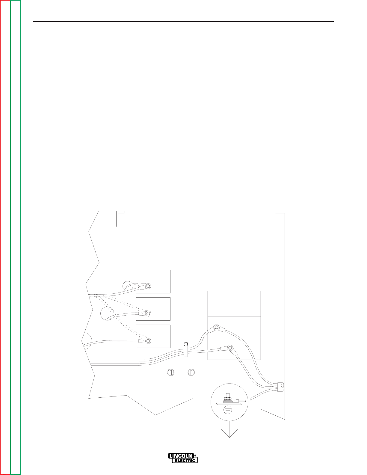
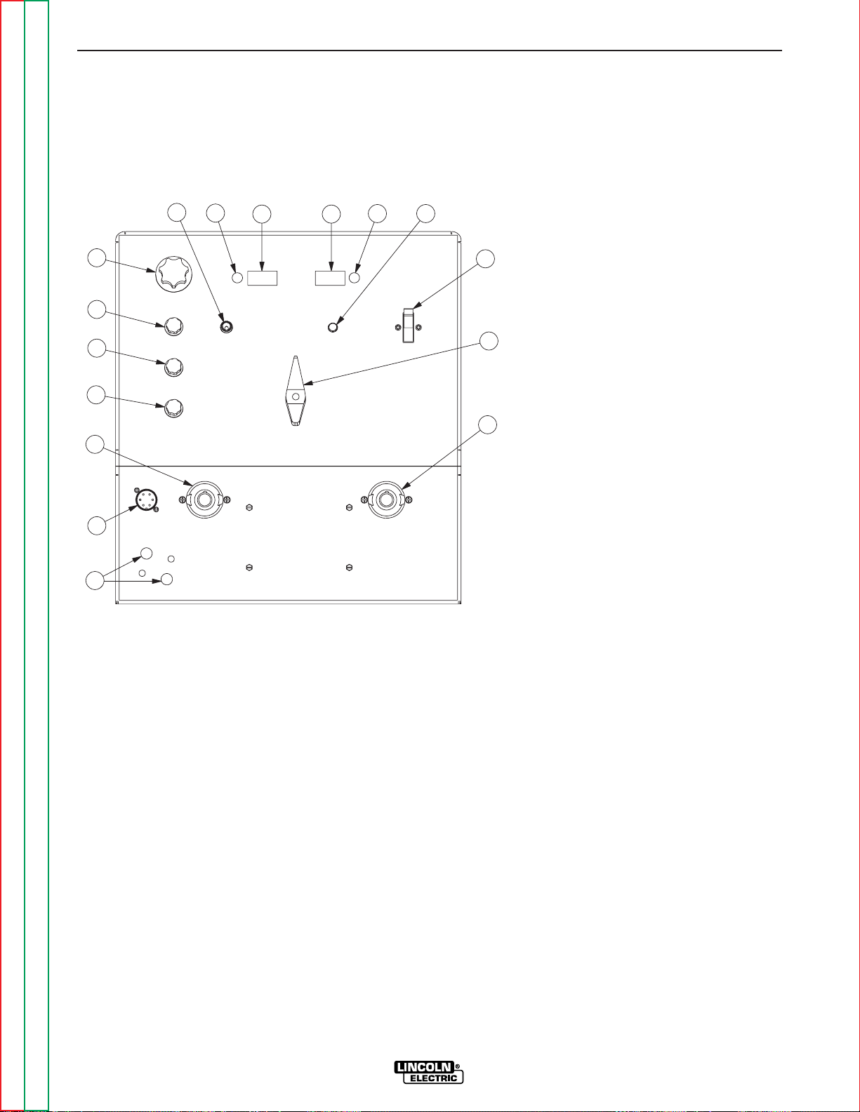
See Figure A.1 for the location of the rating plate, the
entry hole, and the reconnect panel.
FIGURE A.1
1. Input Entry 4. 220V Receptacle & Breaker
2. Rating Plate (50/60 HZ. Machines Only.)
3. 115V Receptacle & Breaker 5. Gas Input Fitting
(60 HZ. Machines only)
Remove the right case side to reveal the reconnect
panel. Welder supply line entry provision is in the case
rear panel. Entry is through a 1.4 inch (36 mm) diameter hole in the case back.
All connections should be made in accordance with all
local codes and national electrical codes. Installation
by a qualified electrician is recommended.
1. Connect the terminal marked (at the base of the
welder below the reconnect panel) to an earth
ground.
2. Connect the imput leads to terminals marked L1 (U)
and L2 (V) on the reconnect panel. Use a single
phase line or one phase of a two or three phase line.
INSTALLATION
A-4 A-4
SQUARE WAVE TIG 275
Return to Section TOC Return to Section TOC Return to Section TOC Return to Section TOC
Return to Master TOC Return to Master TOC Return to Master TOC Return to Master TOC
1
2
5
3
4
Page 11
Fuse the input circuit with the recommended super lag
fuses or delay type1circuit breakers. Choose an input
and grounding wire size according to local or national
codes or refer to the
Technical Specifications
page at
the beginning of this section. Using fuses or circuit
breakers smaller than recommended may result in
“nuisance” tripping from welder inrush currents even if
not welding at high currents.
Unbalanced AC TIG welding draws higher input currents than those for Stick, DC TIG, or Balanced AC TIG
welding. The welder is designed for these higher input
currents. However, where unbalanced AC TIG welding
above 180 amps is planned, the higher input currents
require larger input wire sizes and fuses per the
Technical Specifications
page at the beginning of this
section.
1
Also called “inverse time” or “thermal/magnetic” circuit breakers, circuit
breakers which have a delay in tripping action that decreases as the magnitude of the current increases.
INPUT RECONNECT PROCEDURE
On multiple input voltage welders, be sure the reconnect panel is connected per the following instructionsfor the voltage being supplied to the welder.
Designations on the reconnect panel, LOW, MID, and
HIGH correspond to the nameplated input voltages of
a triple voltage welder. Dual voltage welders use only
LOW and HIGH.
EXAMPLE: On a 208/230/460 volt welder, LOW is
208V, MID is 230V, and HIGH is 460V.
Make sure all connections are tight. Replace the case
side and all screws.
INSTALLATION
A-5 A-5
SQUARE WAVE TIG 275
Return to Section TOC Return to Section TOC Return to Section TOC Return to Section TOC
Return to Master TOC Return to Master TOC Return to Master TOC Return to Master TOC
FIGURE A.2
RECONNECT PANEL INSTRUCTIONS FOR 208/230/460/Domestic model
460V
3 (MID)
4 (HIGH)
230V
power at the disconnect switch or fuse box before making any connections. Use
input and grounding lead sizes as specified in the operating manual. Failure to follow
instructions below can cause immediate failure of components within the welder.
Powered by high voltage which can kill. Turn off all input
5.
208V
2.
L1 (U)
4.
3.
2 (LOW)
1.
Connect the input power leads to the input terminals, L1 (U) and L2 (V), at the right
below. Connect the input power leads with the hardware provided. Completely
tighten all fasteners.
Connect a grounding lead to the ground stud located on the machine base near
the input terminals.
Welders are shipped connected for the highest rated single phase input voltage
with the lead marked "A" connected to the stud marked "4 (HIGH)".
For middle range input, reconnect the lead marked "A" to the stud marked "3 (MID)".
For low range input, reconnect the lead marked "A" to the stud marked "2 (LOW)".
SINGLE PHASE INPUT POWER SUPPLY CONNECTION INSTRUCTIONS:
SINGLE
PHASE
INPUT
L2 (V)
POWER FACTOR CAPACITORS
LEADS FOR OPTIONAL
208/230/460 DOMESTIC MODEL
WARNING:
Page 12
USER SUPPLIED CONNECTORS
The Square Wave TIG 275 should be permanently
wired into the power system. No plugs or connectors
are necessary.
OUTPUT CONNECTIONS
To avoid being startled by a high frequency shock, keep
the TIG torch and cables in good condition.
ELECTRIC SHOCK can kill.
• Turn the power switch of the power
source “OFF” before installing
adapters on cable or when connecting
or disconnecting adapter plugs to
power source.
See Figure B.1 for the location of the work and electrode terminals, the gas and optional water solenoids,
and the Remote Receptacle.The Square Wave TIG
275 is equipped with Twist-Mate connectors for the
electrode and work connection.
WORK CABLE CONNECTION
The Twist-Mate connection allows fast and reliable
work cable attachment to the work terminal of the
Square Wave TIG 275 welding power supply.
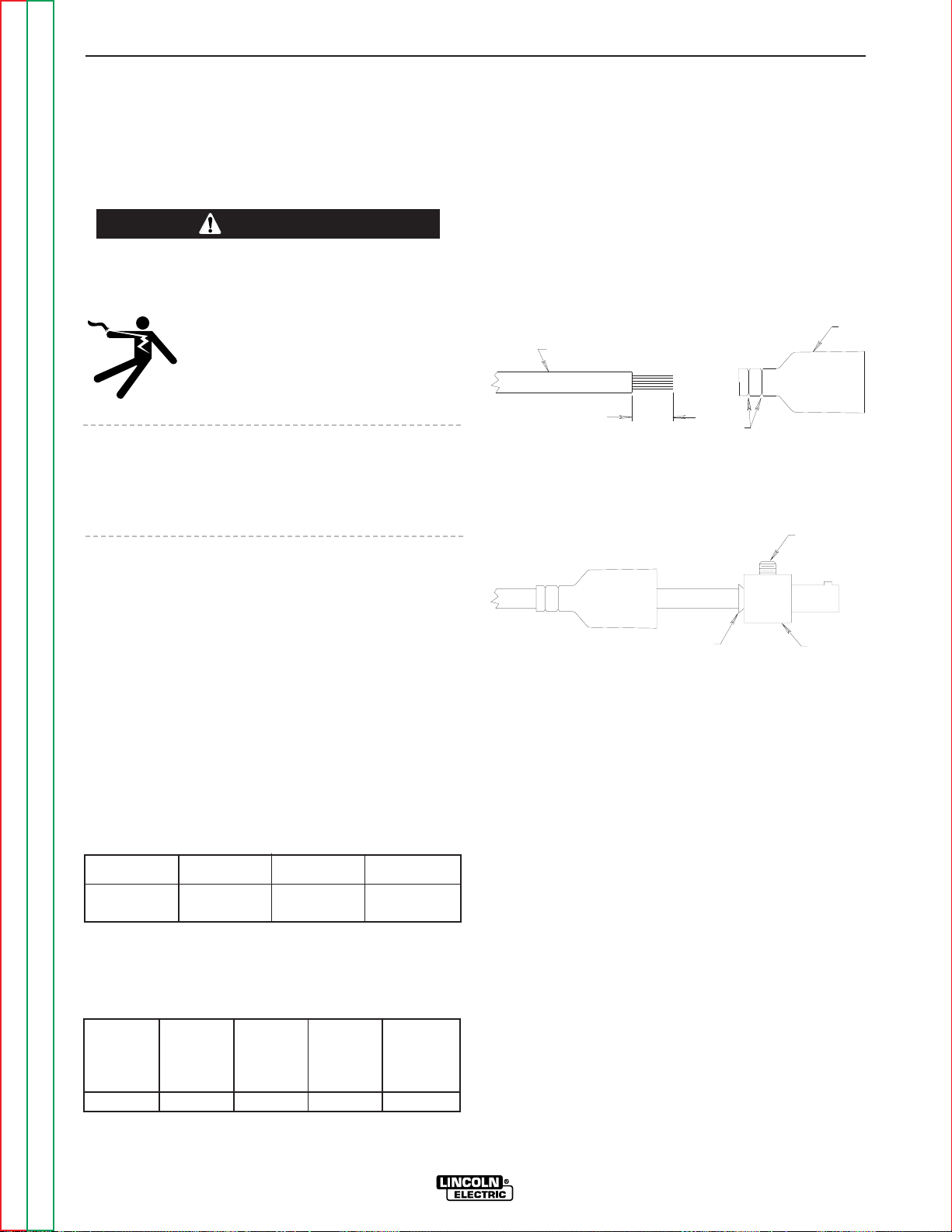
Assemble the work cable by attaching the correct
Twist-Mate adapter and work clamp to an adequatelysized welding cable. The Twist-Mate cable plug included with the machine is designed to accept a welding
cable size of of #2 to #1. See Table A.1 and A.2 for recommended sizes and corresponding hardware.
Assemble the correct Twist-Mate-adapter plug to the
work cable as follows:
1. Skin the cable jacket to 1.00 in (25.4 mm) for a #2
thru 2/0 (35 thru 70 mm2) cable. Skin the cable
jacket to 1.50 in (38.1 mm) for a 2/0 thru 3/0 (70 thru
95 mm2) cable.
2. If necessary , trim the cable end of the rubber boot to
match the diameter of the cable.
3. Slide the rubber boot onto the skinned cable end.
Use soap for lubricant if required.
4. Slide the copper tube into the brass plug. Insert
skinned cable into the copper tube.
5. Tighten set screw(s) to collapse copper tube.
Screw(s) must apply firm pressure against welding
cable.
6. Slide the rubber boot over the brass plug. The rubber boot must be positioned to completely cover all
electrical surfaces after the plug is locked into the
receptacle. For more details see S18737PRINT or
instructions included with the adapter kit.
INSTALLATION
A-6 A-6
SQUARE WAVE TIG 275
Return to Section TOC Return to Section TOC Return to Section TOC Return to Section TOC
Return to Master TOC Return to Master TOC Return to Master TOC Return to Master TOC
WARNING
TABLE A.1
Cable Sizes for Combined Lengths of Copper
Electrode and Work Cable
Machine Size
Lengths up to
100 ft 100 to 200 ft 200 to 250 ft
275 Amp
40% Duty Cycle #1 (42.4mm2) 1/0 (53.5mm2) 2/0 (67.4mm2)
TABLE A.2
Recommended Work and Stick Electrode
Components
Twist Mate
Cable Plug
for Work
Lead
(#2 to #1)
Twist Mate
Cable Plug
for Work
Lead
(1/0 to 2/0)
Twist Mate
Cable Plug
for Work
Lead
(2/0 to 3/0)
Work
Clamp
Electrode
Holder
K852-50 K852-70 K852-95 K910-1 K909-4
SEE
WELDING CABLE
TRIM
ABOVE
BOOT
COPPER TUBE
SET SCREW
(70-95 SIZE MAY
HAVE 2 SET
BRASS PLUG
SCREWS)
Page 13

TIG TORCH CONNECTION
The Twist-Mate connection allows fast and reliable TIG
torch attachment to the electrode terminal of the
Square Wave TIG 275 welding power supply. TwistMate TIG adapters are made of brass, combining high
electrical conductivity with mechanical strength. They
are available in several sizes and styles to accommodate a wide selection of gas and water-cooled TIG
torches.
• For Air-Cooled TIG Torch connections refer to
TWIST-
MA TE ADAPTER for LA-9 and LA-17 TIG TORCH
section.
• For Water-Cooled TIG TORCH connections refer to
TWIST-MATE ADAPTER for LW-18 and LW-20 TIG
TORCH
Section.
Any torch having hoses and cables equipped with
Compressed Gas Association (CGA) style fittings can
be connected to an appropriate Twist-Mate adapter
(see
ACCESSORIES
section). The power source
must be switched off while making any of these
connections.
Do not operate a water-cooled torch without an adequate coolant supply. Set-ups using recirculated
coolant require that the cooler be switched on and running. If the water solenoid valve option is used with a
cooler, the coolant does not flow until the solenoid is
actuated.
For set-ups using water as a single-pass through
coolant, install a strainer into the system upstream of
the Square Wave TIG 275 to reduce the concentration
of particles that could contaminate the system.
Otherwise, flow passages could become obstructed or
clogged, causing torch overheating or failure. The
optional water solenoid valve may also malfunction.
When the water solenoid valve option is installed into
the Square Wave TIG 275, connect the coolant supply
line from either cooler outlet or single-pass supply to
the “Water Inlet” fitting located on the machine’s case
front. Connect the TIG torch’s smaller water fitting to
the “Water Out” fitting also located on the case front. A
non-metallic coolant line is required between the electrode connection and the drain or cooler inlet. This
reduces the possibility of an electrical hazard.
TIG welding torches are available with 12.5 and 25 foot
cables (3.8m and 7.6m, respectively). Use the shorter
length whenever possible to reduce radio interference
problems.
CYLINDER could explode if
damaged.
• Keep cylinder upright and chained to a
support.
• Keep cylinder away from areas where it could be
damaged.
• Never allow the torch to touch the cylinder.
• Keep cylinder away from live electrical circuits.
• Maximum inlet pressure 150 psi.
The high-pressure cylinder of inert shielding gas must
be equipped with a flow regulator that limits the gas
pressure to 150 psi maximum at the machine’s gas
inlet. This brass inlet fitting is located on the rear panel
of the Square Wave TIG 275. Install a hose between
the gas flow meter and the inlet fitting.
For other conditions, consult the manufacturer’s
instructions for the water cooler or TIG torch being
used.
INSTALLATION
A-7 A-7
SQUARE WAVE TIG 275
Return to Section TOC Return to Section TOC Return to Section TOC Return to Section TOC
Return to Master TOC Return to Master TOC Return to Master TOC Return to Master TOC
WARNING
Page 14

INSTALLATION
A-8 A-8
SQUARE WAVE TIG 275
Return to Section TOC Return to Section TOC Return to Section TOC Return to Section TOC
Return to Master TOC Return to Master TOC Return to Master TOC Return to Master TOC
TWIST-MATE ADAPTER FOR LA-9
and LA-17 TIG TORCH
The Twist-Mate connection allows fast and reliable TIG
torch connections to the electrode terminal of the
Square Wave TIG 275. The Twist-Mate adapter, strain
relief boot and retaining compound needed to connect
an LA-9 or LA-17 torch (or any equivalent air-cooled
TIG torch with a right-hand male 3/8-24 fitting) are
included with the Square Wave TIG 275.
Assemble the the LA-9 or LA-17 TIG torch to the TwistMate adapter as follows:
1. Slide the strain relief boot over the TIG torch’s
power cable with gas fitting.
2. Apply a small amount of retaining compound to the
fitting threads as shown. Thread the fitting to the
TIG adapter and tighten to ensure a sealed gas
connection and a good electrical connection. (35-45
in-lbs)
3. Hold the TIG adapter, with cable installed, firmly in
place by securing it into the Twist-Mate receptacle
on the power source or into a padded vise. Align
the hex in the boot with the hex on the adapter.
Firmly push the boot onto the adapter, rocking the
boot to assist installation. Use soap for lubricant if
required.
4. Examine the strain relief boot and TIG adapter for
correct assembly. The boot should nest into the
Twist-Mate receptacle on the power source. All
electrical surfaces should be completely covered
when in the Twist-Mate receptacle on the power
source. For more details see M191 15PRINTincluded with the machine.
TWIST-MATE ADAPTER FOR LW-18
and LW-20 TIG TORCH
The Twist-Mate connection allows fast and reliable TIG
torch connections to the electrode terminal of the
Square Wave TIG 275. The Twist-Mate adapter and
strain relief boot needed to connect an L W-18 or LW-20
torch (or any equivalent water-cooled TIG torch with
the fittings shown in the diagrams under step 2 and 3)
are included with the Square Wave TIG 275.
Assemble the the LW-18 or LW-20 TIG torch to the
Twist-Mate adapter as follows:
1. Slide the strain relief boot over the TIG torch’s
power/water cable (large fitting) and gas hose
(small fitting without notches on hex). Also slide a
water hose into the strain relief boot as shown.
2. Thread the power/water cable (large fitting) from the
torch to the large port on the TIG adapter and tighten to ensure a water tight connection. Next, thread
the gas hose (small fitting without notches on hex)
to the port marked “G” on the TIG adapter and tighten to ensure a sealed gas connection. Next, thread
the water hose to cooler (or to water drain) to the
port marked “W” on the TIG adapter.
3. Check all connections made in step 2 for gas and
water leaks before proceeding.
TIG ADAPTER
TIG TORCH POWER CABLE WITH GAS FITING
RETAINING COMPOUND
STRAIN RELIEF BOOT
STRAIN RELIEF BOOT
TIG ADAPTER
WATER HOSE
GAS HOSE FROM TORCH
POWER/WATER CABLE FROM TORCH
COMPLETED ASSEMBLY
G
W
PORT (RH 5/8-18)
PORT (LH 5/8-18)
GAS CONNECTION
CONNECTION
POWER/WATER
PORT (LH 7/8-14)
WATER CONNECTION
W
G
"IN"
OR
COOLANT
OPTIONAL
WATER HOSE
"OUT"
COOLANT
FLOW
WATER SOLENOID KIT
WATER
(RH 5/8-18 MALE FITTING)
WATER HOSE FROM TORCH
GAS HOSE FROM TORCH
(SEPARATELY PROVIDED)
(SEPARATELY PROVIDED)
HOSE COUPLER
COOLANT
LW-18 OR LW-20
TIG TORCH
(SEPARATELY PROVIDED)
(LH 5/8-18 MALE FITTING)
"OUT"
"IN"
COOLANT
MAGNUM
CONNECTION DIAGRAM
POWER/WATER CABLE FROM TORCH
(LH 7/8-14 MALE FITTING)
WATER HOSE
(SEPARATELY PROVIDED)
WATER COOLER
Page 15

4.
Hold the TIG adapter , with cables and hoses installed,
firmly in place by securing it into the T wist-Mate receptacle on the power source or into a padded vise.
Apply a thin film of lubricant to the boot’s lead in
chamfer area. Also apply lubricant to the lead in
chamfer and 2” diameter on the TIG adapter. Next
align the strain relief boot keys with the TIG adapter
slots. Now firmly push the boot onto the adapter,
rocking the boot to assist installation.
5. Examine the strain relief boot and TIG adapter for
correct assembly. The boot should nest into the
Twist-Mate receptacle on the power source. The
boot face will be 1/8 inch away from the machine
front. All electrical surfaces should be completely
covered when in the Twist-Mate receptacle on the
power source. For more details see M19116PRINT
included with the machine.
STICK ELECTRODE CABLE
CONNECTION
The Twist-Mate connection allows fast and reliable stick
electrode attachment to the electrode terminal of the
Square Wave TIG 275 welding power supply.
Assemble the electrode cable by attaching the correct
Twist-Mate adapter and electrode holder to an adequately-sized welding cable. See Table A.1 and A.2 for
recommended sizes and corresponding hardware.
Assemble the correct Twist-Mate adapter plug to the
stick electrode cable as detailed in
Work Cable
Connection.
DO NOT CONNECT A TIG TORCH AND STICK ELECTRODE CABLE AT THE SAME TIME. THEY WILL
BOTH BE ELECTRICALLY HOT WHENEVER THE
OUTPUT CONTACTOR IS ENERGIZED.
INSTALLATION
A-9 A-9
SQUARE WAVE TIG 275
Return to Section TOC Return to Section TOC Return to Section TOC Return to Section TOC
Return to Master TOC Return to Master TOC Return to Master TOC Return to Master TOC
WARNING
COMPLETED ASSEMBLY
Page 16

NOTES
A-10 A-10
SQUARE WAVE TIG 275
Return to Section TOC Return to Section TOC Return to Section TOC Return to Section TOC
Return to Master TOC Return to Master TOC Return to Master TOC Return to Master TOC
Page 17

Section B-1 Section B-1
SQUARE WAVE TIG 275
TABLE OF CONTENTS
- OPERATION SECTION -
Operation...............................................................................................................................Section B
Safety Precautions......................................................................................................................B-2
General Description ....................................................................................................................B-3
Recommended Processes and Equipment................................................................................B-3
Design Features and Advantages...............................................................................................B-3
Welding Capability .....................................................................................................................B-4
Limitations...................................................................................................................................B-4
Controls and Settings.................................................................................................................B-5
Welding Operation ......................................................................................................................B-6
TIG Welding..........................................................................................................................B-6
TIG Welding Guidelines........................................................................................................B-6
TIG Welding Sequence of Operation (2-Step TIG Mode) ....................................................B-7
TIG Welding Sequence of Operation (4-Step TIG Mode) ....................................................B-7
Hand and Foot Amptrol Operation.......................................................................................B-8
Advanced TIG Welding Features ................................................................................................B-8
AC Wave Balance and Auto Balance™......................................................................................B-8
Stick Welding..............................................................................................................................B-9
Auxiliary Power ...........................................................................................................................B-9
60 Hertz Domestic Machines...............................................................................................B-9
50/60 Hertz European Machines..........................................................................................B-9
Return to Master TOC Return to Master TOC Return to Master TOC Return to Master TOC
Page 18
OPERATION
B-2 B-2
SQUARE WAVE TIG 275
Return to Section TOC Return to Section TOC Return to Section TOC Return to Section TOC
Return to Master TOC Return to Master TOC Return to Master TOC Return to Master TOC
ELECTRIC SHOCK
can kill.
• Do not touch electrically live parts or
electrode with skin or wet clothing.
•
Insulate yourself from work and ground.
• Always wear dry insulating gloves.
•
Read and follow “Electric Shock Warnings”
in the Safety section if welding must be performed under electrically hazardous conditions such as welding in wet areas or on or
in the workpiece.
FUMES AND GASES
can be dangerous.
• Keep your head out of fumes.
• Use ventilation or exhaust to
remove fumes from breathing
zone.
WELDING SPARKS
can cause fire or
explosion
• Keep flammable material away.
• Do not weld on containers that
have held combustibles.
ARC RAYS
can burn.
• Wear eye, ear and body
protection.
SAFETY PRECAUTIONS
Read and understand this entire section before operating the machine.
Observe additional Safety Guidelines detailed in
the beginning of this manual.
WARNING
Page 19

GENERAL DESCRIPTION
The Square Wave TIG 275 is a constant current, single
range square wave AC/DC TIG (GTAW) arc welding
power source with built-in high frequency stabilization.
It also has stick (SMAW) capability. A TIG Pulser Kit,
Power Factor Capacitor Kit, and a Water Solenoid Kit
are available as field installed options.
The Square Wave TIG 275 includes advanced features
such as Digital Voltage and Current Meters, Auto
Balance™, 2-Step/4-Step operation, adjustable Down
slope Time control and Fan as Needed. It also features
Twist Mate connections for the electrode and work
leads. In addition, fixed preflow and variable post flow
timers are included to control the shielding gas, as well
as the water flow when using the optional water solenoid.
RECOMMENDED PROCESSES AND
EQUIPMENT
The Square Wave TIG 275 is recommended for the
TIG (GTAW) and stick (SMAW) welding processes
within its output capacity of 5 to 315 amps, on both AC
and DC polarity. It is compatible with all Magnum TIG
accessories, as well as many industry standard items,
such as TIG torches, hoses, and water coolers.
DESIGN FEATURES AND
ADVANTAGES
• Meets NEMA CLASS II (40) and IP21S environmental certification. (Will be CSA NRTL/C certified in the
future.) Domestic and Canadian Models Only.
• Meets IEC-974-1 and IP21S environmental certification. (Will be CE certified in the future.) European
Model Only.
• Built in Digital Ammeter and Voltmeter for precise
process control. This includes a persistence feature
which captures and continues to display the peak
welding current and it’s corresponding voltage for five
seconds after the weld is completed.
• AC Wave Balance control knob provides flexibility to
the customer. Set it to the Auto Balance position and
the circuitry automatically provides the proper amount
of cleaning and penetration for normal AC TIG welding. For special applications simply dial in the amount
of cleaning and penetration needed.
• Fan As Needed (FAN) circuit turns ‘ON’ the fan only
when cooling is needed. FAN minimizes the amount
of dust, dirt, and other foreign material drawn into the
machine. A build up of these materials can cause
excessive operating temperatures and nuisance shut
downs.
• 2-STEP/4-STEP TIG/STICK mode control switch. 4STEP mode requires the use of an optional Arc Start
Switch. This welding mode reduces fatigue by eliminating the need to manually control the weld current
during the weld.
• Down Slope Time control is active in 4-STEP TIG
mode. It controls the amount of time (approximately
1 to 10 seconds) it takes the weld current to ramp
down from the Preset level to 25% ±10% of that level.
• Post Flow Time control is active in the 2 and 4-STEP
TIG modes. It controls the amount of time (approximately 5 to 50 seconds) the shielding gas flows after
the weld is completed.
• Robotic Interface connection on the PC board can be
connected to the machines Remote Receptacle for
automated welding procedures. This interface allows
remote control of the trigger and output current of the
machine as well as providing a signal when the weld
is established. (For details contact the Lincoln Automation Center)
• Built in High Frequency Generator automatically performs in the correct mode. If the machine is in STICK
mode, the HF stays ‘OFF’. IF the machine is in DC
TIG mode, the HF comes ‘ON’ and stays on until the
arc is established. IF the machine is in AC TIG mode,
the HF comes ‘ON’ and stays on continuously to stabilize the arc.
• Automatic Local/Remote current selection. The
machine automatically senses if an Amptrol, Arc Start
Switch or TIG Pulser is plugged in and transfers current control from local to remote.
• Built in preflow time of 0.5 seconds. Preflow time is
eliminated if welding restarts during the pervious
weld’s post flow. This avoids unnecessary delays
when making repeated welds.
• Simple dial and switch design provides the customer
with flexible control of the welding process without
unnecessary complication. Controls which are not
needed in the weld mode selected are automatically
locked out.
• Twist Mate connectors are provided for the electrode
and work connections. This style connector makes
the gas and current connections for the TIG torch at
the same time. (Adaptor plugs are provided)
• DC+/AC/DC- Polarity Switch allows the welder to
change polarity without reconnecting leads.
OPERATION
B-3 B-3
SQUARE WAVE TIG 275
Return to Section TOC Return to Section TOC Return to Section TOC Return to Section TOC
Return to Master TOC Return to Master TOC Return to Master TOC Return to Master TOC
Page 20

Return to Section TOC Return to Section TOC Return to Section TOC Return to Section TOC
Return to Master TOC Return to Master TOC Return to Master TOC Return to Master TOC
OPERATION
B-4 B-4
SQUARE WAVE TIG 275
• Provides excellent arc starting and stability throughout the machines wide current range (5 to 315 Amps)
to handle the vast majority of TIG welding applications.
• Simple output current dial allows the user to preset
the peak current within the full output range of the
machine.
• Highly resistant to AC arc rectification.
• Thermostatically protected to prevent equipment
damage.
• No tungsten spitting within current range of electrode.
• Designed to make maintenance and servicing easy.
• 115 Volt Receptacle with 10 Amp Circuit Breaker.
Domestic and Canadian Models Only.
• 220 Volt European (Schuko) type Receptacle with 2
Amp Circuit Breaker. European Model Only.
• Low Voltage Trigger Circuit (18 VAC) for maximum
operator safety.
• Remote Receptacle for Amptrol or Arc Start Switch
connection.
• Gas Valve Inlet fitting conforms to Compressed Gas
Association (CGA) standards.
WELDING CAPABILITY
The Square Wave TIG 275 is rated at 275 amps, 31
volts, at 40% duty cycle on a ten minute basis for DC
TIG and AC/DC stick processes. It is capable of higher duty cycles at lower output currents. If the duty
cycle(s) are exceeded, the thermostatic protection will
shut off the output until the machine cools to a normal
operating temperature.
LIMITATIONS
The Square Wave TIG 275 is not recommended for AC
TIG welding when high concentrations of helium gas
are used for shielding. This causes starting and arc
rectification problems. Also the Square Wave 275 is
not recommended for arc gouging due to it's limited
output capacity. The Square Wave TIG 275 is also not
recommended for pipe thawing.
Page 21
OPERATION
B-5 B-5
SQUARE WAVE TIG 275
Return to Section TOC Return to Section TOC Return to Section TOC Return to Section TOC
Return to Master TOC Return to Master TOC Return to Master TOC Return to Master TOC
1. Current Control - This knob is used to set the
welding current from 5 to 315 amps. Read the
complete Operating Instructions section for more
information on Local and Remote setting of current.
2. AC Wave Balance Control - This knob is active in
the AC TIG mode only. It is used to set the amount
of cleaning and/or penetration produced during an
AC TIG weld. Auto Balance™ automatically sets
the AC Wave balance according to the welding current. If manual adjustment is desired, the balance
can be adjusted from +0 (maximum cleaning)
to +10 (maximum penetration). Read the
Advanced Features section for a complete explanation of the AC Wave Balance.
3. Post Flow Time Control - This knob is active in
the TIG mode only. It adjusts the post flow time
from 5 to 50 seconds for shielding gas. It also
adjusts cooling water flow when the optional
K1621-1 Water Solenoid Kit is used.
4. Down Slope Time Control - This knob is active in
4-Step TIG mode only. It adjusts the time (from 0.5
to 10 seconds) the welding output takes to ramp
down from the preset level to 25% of that level.
5. 2-Step/4-Step TIG/Stick Mode Control Switch -
This switch selects the welding mode desired: TIG
2-Step, TIG 4-Step, or Stick. Read the complete
Operating Instructions section for more information
on TIG 2-Step and TIG 4-Step.
6. Trimmer Potentiometers - Allows the meters to be
calibrated in the field.
7. Digital Ammeter - The ammeter displays actual
welding current during a weld cycle and displays the
peak current for approximately 5 seconds after
welding is complete. Read the complete Operating
Instructions section for more information on the
Ammeter.
10
6
5
7 8
6 9
11
12
13
14
15
1
2
3
4
1. Output Control Knob
2. AC Wave Balance Knob
3. Post Flow Knob
4. Down Slope Time Knob
5. Mode Switch
6. Trimmer Potentiometer
7. Digital Ammeter
8. Digital Voltmeter
9. Thermal Protection Light
10. Power Switch
11. Polarity Switch
12. Electrode Connection (Twist-Mate Connector)
13. Work Connection (Twist-Mate Connector)
14. Remote Control Amphenol
15. Water Solenoid (Optional)
CONTROLS AND SETTINGS
All operator controls and adjustments are located on the case front of the Square Wave TIG 275. Refer to Figure
B.1 and corresponding explanations following.
FIGURE B.1 - CONTROL PANEL
Page 22

8. Digital Voltmeter - This meter displays welding
voltage, as measured on the output studs of the
Square Wave TIG 275. After welding is complete,
the meter displays the welding voltage corresponding to the peak welding current and displays
this value for approximately 5 seconds.
9. Thermal Protection Light - A yellow light which
only lights when an over temperature situation
occurs. See the
Maintenance Section
for more
information on thermostatic protection.
10. Power Switch - Controls the input power to the
Square Wave TIG 275.
11. Polarity Switch - Selects DC+, AC or DC- welding
polarity without reconnecting leads. DO NOT
SWITCH WHILE WELDING.
12. Twist Mate Electrode and
13. Work Connections - Easy to connect electrode
and work connections. This style Electrode
Connection makes the gas and current connections for the TIG torch at the same time. (Adapter
plugs are provided with the machine.)
14. Remote Receptacle - For Amptrol, Arc Start
Switch or Robotic Interface connection.
15. Optional Water Solenoid Connections - Easy to
install this optional feature which allows for water
flow control for water cooled torches.
WELDING OPERATION
TIG WELDING
Familiarize yourself with the Controls and Settings
Section before attempting operation of the Square
Wave TIG 275.
TIG WELDING GUIDELINES
TIG welding can be done in either the TIG 2-Step or
the TIG 4-Step Weld Mode. TIG 2-Step is typically
used with Hand or Foot Amptrols, with Remote Current
control. TIG 4-Step typically uses an Arc Start switch
and Local Current Control, because it provides a very
brief current upslope, and a .5 to 10 second adjustable
current downslope. TIG 4-Step also functions like a
trigger interlock, making it unnecessary to hold down
the Arc Start switch during a weld. This feature
requires that the remote control device in use must
have separate Arc Start and Output Control mechanisms. Read the TIG Welding Sequence of Operation
sections for more details on 2-Step and 4-Step operation.
Recommended tungsten electrode sizes, stickouts,
currents, cup or nozzle sizes are shown in Table B.1.
SINCE WELDING APPLICATIONS CAN VARY, THIS
CHART IS INTENDED AS A GUIDE ONLY.
OPERATION
B-6 B-6
SQUARE WAVE TIG 275
Return to Section TOC Return to Section TOC Return to Section TOC Return to Section TOC
Return to Master TOC Return to Master TOC Return to Master TOC Return to Master TOC
(1) When used with argon gas. The current ranges shown must be reduced when using argon/helium or
pure helium shielding gasses.
(2) Tungsten electrodes are classified as follows by the American Welding Society (AWS):
Pure . . . . . . . . . . . . . . . EWP
1% Thoriated . . . . . . . . EWTh-1
2% Thoriated . . . . . . . . EWTh-2
Though not yet recognized by the AWS, Ceriated Tungsten is now widely accepted as a substitute for
2% Thoriated Tungsten in AC and DC applications.
(3) DCEP is not commonly used in these sizes.
(4) TIG torch nozzle “sizes” are in multiples of 1/16ths of an inch:
#4 = 1/4 in. (6 mm)
#5 = 5/16 in. (8 mm)
#6 = 3/8 in. (10 mm)
#7 = 7/16 in. (11 mm)
#8 = 1/2 in. (12.5 mm)
#10 = 5/8 in. (16 mm)
(5)
TIG torch nozzles are typically made from alumina ceramic. Special applications may require lava nozzles,
which are less prone to breakage, but cannot withstand high temperatures and high duty cycles.
TABLE B.1 TYPICAL CURRENT RANGES FOR TUNGSTEN ELECTRODES
(2)
.010 (.25)
0.020 (.50)
0.040 (1.0)
1/16 (1.6)
3/32 (2.4)
1/8 (3.2)
5/32 (4.0)
3/16 (4.8)
1/4 (6.4)
2-15
5-20
15-80
70-150
150-250
250-400
400-500
500-750
750-1000
(3)
(3)
(3)
10-20
15-30
25-40
40-55
55-80
80-125
2-15
5-15
10-60
50-100
100-160
150-210
200-275
250-350
325-450
2-15
5-20
15-80
70-150
140-235
225-325
300-400
400-500
500-630
2-15
10-20
20-30
30-80
60-130
100-180
100-240
190-300
250-400
---
5-20
20-60
60-120
100-180
160-250
200-320
290-390
340-525
3-8 (2-4)
5-10 (3-5)
5-10 (3-5)
5-10 (3-5)
13-17 (6-8)
15-23 (7-11)
21-25 (10-12)
23-27 (11-13)
28-32 (13-15)
3-8 (2-4)
5-10 (3-5)
5-10 (3-5)
9-13 (4-6)
11-15 (5-7)
11-15 (5-7)
13-17 (6-8)
18-22 (8-10)
23-27(11-13)
#4, #5, #6
#5, #6
#6, #7, #8
#8, #10
1%, 2%
Thoriated
Tungsten
1%, 2%
Thoriated
Tungsten
Pure
Tungsten
1%, 2%
Thoriated
Tungsten
Zirconiated
Pure
Tungsten
1%, 2%
Thoriated
Tungsten
Zirconiated Aluminum
Stainless
Steel
Tungsten
Electrode
Diameter
in. (mm)
TIG Torch
Nozzle
Size
(4), (5)
DCEN (-) DCEP ( +)
Unbalanced Wave Balanced Wave
AC Approximate Argon
Gas Flow Rate
C.F.H. (1/min.)
Page 23

TIG WELDING SEQUENCE OF OPERATION
(2-Step TIG Mode)
1. Connect an Arc Start Switch or an Amptrol to the
Remote Amphenol.
2. Turn the welder, gas supply and water supply (if
equipped), on. The digital ammeter/voltmeter displays will illuminate when the power is on.
3. Select the 2-Step TIG Mode with the 2-Step/4-Step
TIG/Stick switch.
4. Set the maximum output current using the output
control knob.
5. Select AC or DC- electrode polarity. See Table B.2.
6. If welding with AC polarity, set the AC Wave
Balance Knob to Auto Balance™. This gives the
optimum ratio between cleaning and penetration,
automatically adjusted of the AC Wave Balance is
desired, adjust the wave balance to the desired
settings. See the Advanced Features section for
more information on setting and using the AC
Wave Balance.
7. Set the post flow time with the post flow knob. Post
flow control knob adjusts the time that the shielding
gas flows (and cooling water flow, if the optional
water solenoid is used) after the weld cycle. Use
short post flow times with low currents and small
tungstens, use long post flow times at high output
currents with large tungstens.
8. Press and release the Arc Start Switch, and set the
gas flow meter. The welder is now ready for welding.
9. Position the tungsten electrode at the start of the
weld at a 65° to 75° angle with the horizontal so
that the electrode is approximately 1/8” (4 mm)
above the work piece. Press the Arc Start Switch.
This opens the gas (and optional water solenoid)
valves to automatically purge air from the hose and
torch. After a 0.5 second preflow time, the high frequency becomes available to strike the arc.
10. Hold the Arc Start Switch or Amptrol down until an
arc is established. If using an Amptrol, read the
Section on Hand and Foot Amptrol Operation.
Release the Arc Start Switch or Amptrol to stop the
arc and start the Post Flow timer. After the Post
Flow time has expired, the gas and (optional water
solenoid) valves will close. To make another weld,
repeats steps 9 and 10.
TIG WELDING SEQUENCE OF OPERATION
(4-Step TIG Mode)
1. Connect an Arc Start Switch to the Remote
Amphenol.
2. Turn the welder, gas supply and water supply (if so
equipped), on. The digital ammeter/voltmeter display will illuminate when the power is on.
3. Select the 4-Step TIG Mode with the 2-Step/4-Step
TIG/Stick switch.
4. Set the maximum output current using the output
control knob.
5. Select AC or DC- electrode polarity. See Table B.2.
6. If welding with AC polarity, set the AC Wave
Balance Knob to Auto Balance™. This gives the
optimum ratio between cleaning and penetration,
automatically adjusted for the output current. If
manual adjustment of the AC Wave Balance is
desired, adjust the wave balance to the desired
settings. See the Advanced Features section for
more information on setting and using the AC
Wave Balance.
7. Set the Post Flow time with the Post Flow knob.
Post Flow time provides shielding gas flow (and
cooling water, if used) after the weld. Use short
Post Flow times with low currents and small tungstens and long Post flow times at high output currents and large tungstens.
8. Set the Downslope Time with the Downslope Time
Knob. This will adjust the time of the crater fill period.
9. Press and release the Arc Start Switch, to set the
gas flow meter if necessary. The welder is now
ready for welding.
10. Position the tungsten electrode at the start of the
weld at a 65° to 75° angle with the horizontal so
that the electrode is approximately 1/8” (4 mm)
above the work piece. Press the Arc Start Switch.
This opens the gas and water valves to automatically purge air from the hose and torch. After a 0.5
second preflow time, the high frequency becomes
available to strike the arc.
OPERATION
B-7 B-7
SQUARE WAVE TIG 275
Return to Section TOC Return to Section TOC Return to Section TOC Return to Section TOC
Return to Master TOC Return to Master TOC Return to Master TOC Return to Master TOC
TABLE B.2
RECOMMENDED POLARITY
SETTINGS FOR TIG WELDING
Type of Welding
Electrode
Polarity
Stainless Steel
Aluminum & Magnesium
Other Metals
DC-
AC
DC-
Page 24

11. Hold the Arc Start Switch down until an arc is
established. The arc will start at a low current
value that is equal to 25% of the preset current
established in Step 4. It will remain at this current
as long as the Arc Start Switch is closed. Release
the Arc Start Switch. At this point, the Square
Wave TIG 275 will quickly ramp up to the preset
maximum welding current, (0.5 seconds upslope
time) and the weld will continue indefinitely. Press
the Arc Start Switch a second time to initiate the
Downslope time. The current will go down to a
crater fill current that is equal to 25% of the welding current. Release the Arc Start Switch to stop
the arc and start the Post flow timer. After the Post
flow time has expired, the gas and optional water
valves will close. To make another weld, repeat
steps 10 and 11.
HAND AND FOOT AMPTROL OPERATION
Both the Hand and Foot Amptrol work in a similar manner. They are meant to be used for remote current con trol. The TIG 2-Step mode must be selected when
using an Amptrol for remote current control.
For simplicity , the following explanation will refer only to
"Amptrols", meaning both Foot and Hand models. The
term "minimum" refers to a Foot pedal in the "up" position, as it would be with no foot pressure, or a Hand
Amptrol in the relaxed position, with no thumb pressure. "Maximum" refers to a fully depressed Foot
Amptrol, or a fully extended Hand Amptrol.
The Amptrol is capable of controlling the output current
from 5 amps to the preset current on the output control
knob. For example, if the preset is at 200 amps, the
Amptrol, when depressed just past its minimum position, will cause the Square Wave TIG 275 to weld at 5
amps. At the Amptrol's maximum position, the output
will be near 200 amps.
It is important to note that, for many applications, the
tungsten will not start an arc at only 5 amps. (Refer to
the TIG Welding Guidelines for recommended tungsten
currents.) T o start an arc reliably, it is important to
depress the Amptrol far enough so that the machine
output current is near the tungsten operating range. In
the example above, a 3/32" tungsten may be used on
DC- to weld near 200 amps. To start the weld, the
operator may have to depress the Amptrol approximately 1/4 of the way down, or to nearly 50 amps, in
order to start the arc. Merely depressing the Amptrol to
its 5 amp minimum position will not start the arc.
ADVANCED TIG WELDING FEATURES
AC WAVE BALANCE AND AUTO BALANCE™
The AC Wave Balance feature is unique to the Square
Wave TIG 275. It is active only in AC TIG mode. It controls the amount of positive and negative current in the
AC output.
The Square Wave TIG 275 allows the operator to
select Auto Balance™. This selection provides automatic adjustment of the AC Wave Balance; it is suitable
for most welding conditions. Auto Balance™ gives the
ideal amount of cleaning and penetration, based on the
welding current output.
Manual adjustment of the AC Wave Balance is also
possible. Manual Balance settings vary from 0 (maximum cleaning) to 10 (maximum penetration). Asetting
of 3 yields a balanced output (equal amounts of cleaning and penetration). Use the following as a guide
when setting the Balance manually:
BALANCED (3): The amounts of positive and negative
are the same.
CLEANING (0 to 2): Provides more positive current
than negative current. Since the positive current produces the "cleaning" or oxide removal
on aluminum, this setting is used for welding on
heavily oxidized aluminum.
PENETRATION (4 to 10): Provides more negative cur-
rent than positive. The arc plasma will be more
concentrated and more easily directed to where
the heat is needed. Higher penetration settings
allow a given size of tungsten to carry more current.
CAUTION: Use only the amount of cleaning required
because the greater amount of positive current will
heat the tungsten more and possibly cause it to melt or
"spit". Also, the arc is usually more flared and less stable with more cleaning current.
In general, use just enough "cleaning" to remove
oxides and to give good wetting of the puddle.
OPERATION
B-8 B-8
SQUARE WAVE TIG 275
Return to Section TOC Return to Section TOC Return to Section TOC Return to Section TOC
Return to Master TOC Return to Master TOC Return to Master TOC Return to Master TOC
Page 25

STICK WELDING
1. Turn the welder “on”. The digital ammeter/volt-
meter will illuminate when the power is on.
2. Set the Mode Switch to “STICK”. Set the output
current using the Output Control Knob. No other
functions or adjustments operate in the Stick
Mode.
3. Select the desired DC+/AC/DC- electrode polarity.
4. Clamp the electrode in the electrode holder, start
the weld by lightly touching the electrode to the
work. Stop the weld by pulling the electrode away
from the work piece.
AUXILIARY POWER
60 HERTZ DOMESTIC MACHINES
The Square Wave TIG 275 machines rated for 60 Hz
operation provides 10 amps of 115 volt AC power at a
standard NEMA5-15R receptacle, located on the lower
case back of the machine. This circuit is protected
from shorts and overloading by a 10 amp circuit breaker, located next to the receptacle. The auxiliary circuit
is intended for running water coolers and small power
tools, whose current draw is within the 10 amp rating.
Note that some types of equipment, especially pumps
and large motors, have starting currents which are significantly higher than their running current. These higher starting currents may cause the circuit breaker to
open. If this situation occurs, the user should refrain
from using the Square Wave TIG 275 auxiliary for that
equipment.
50/60 HERTZ EUROPEAN MACHINES
The Square Wave TIG 275 machines rated for 50/60Hz
operation provides 2 amps of 220 volt AC power at a
continental European (Schuko) type receptacle, located on the lower case back of the machine. This circuit
is protected from shorts and overloading by a 2 amp
circuit breaker, located above the receptacle. The auxiliary circuit is intended for running water coolers whose
current draw is within the 2 amp rating of the receptacle. Note that some types of equipment, especially
pumps and motors, have starting currents which are
significantly higher than their running currents. These
higher starting currents may cause the circuit breaker
to open. If this situation occurs, the user should refrain
from using the Square Wave TIG 275 auxiliary for that
equipment.
OPERATION
B-9 B-9
SQUARE WAVE TIG 275
Return to Section TOC Return to Section TOC Return to Section TOC Return to Section TOC
Return to Master TOC Return to Master TOC Return to Master TOC Return to Master TOC
Page 26

NOTES
B-10 B-10
SQUARE WAVE TIG 275
Return to Section TOC Return to Section TOC Return to Section TOC Return to Section TOC
Return to Master TOC Return to Master TOC Return to Master TOC Return to Master TOC
Page 27

TABLE OF CONTENTS
- ACCESSORIES -
Accessories...........................................................................................................................Section C
Accessories Included with Machine ............................................................................................C-2
Optional Accessories ..................................................................................................................C-2
Section C-1 Section C-1
SQUARE WAVE TIG 275
Return to Master TOC Return to Master TOC Return to Master TOC Return to Master TOC
Page 28

ACCESSORIES INCLUDED WITH
MACHINE
K852-50 - Twist Mate Cable Plug for #2 to #1 Work
Lead.
K1622-1 - Twist Mate Adapter Kit for LA9 and LA17
Torches.
K1622-2 - Twist Mate Adapter Kit for LW18 and LW20
Torches.
OPTIONAL ACCESSORIES
Any necessary installation instructions are included for
the following accessories:
K963-1, -2 - Hand Amptrol
K870 - Foot Amptrol
K814 - Arc Start Switch
K559-2 - Magnum®Cooler Mounting Bracket
K932-1 - Undercarriage
K1619-1 - TIG Pulser Kit
K1620-1 - Power Factor Capacitor Kit
K1621-1 - Water Solenoid Kit
K1622-3 - Twist Mate Adapter Kit for LA26 Torch
K852-70 - Twist Mate Cable Plug for 1/0 to 2/0 Work
Lead
K852-95 - Twist Mate Cable Plug for 2/0 to 3/0 Work
Lead
K932-1 Undercarriage. When the undercarriage is
properly installed, the Square Wave TIG 275 lift bail is
nonfunctional. Do not attempt to lift the power source
with the undercarriage attached. THe undercarriage is
desinged for hand moving only; mechanized towing
can lead to personal injury and/or damage to the
Square Wave TIG 275.
K1622-1 Twist-Mate Adapter Kit for LA9 & LA17
Torches (Included with machine)
K1622-2 Twist Mate Adapter Kit for LW18 & LW20
Torches (Included with machine)
K852-50 Twist-Mate Cable Plug for #2 to #1 Work Lead
(Included with machine)
ACCESSORIES
C-2 C-2
SQUARE WAVE TIG 275
Return to Section TOC Return to Section TOC Return to Section TOC Return to Section TOC
Return to Master TOC Return to Master TOC Return to Master TOC Return to Master TOC
Page 29

Return to Master TOC Return to Master TOC Return to Master TOC Return to Master TOC
Section D-1 Section D-1
SQUARE WAVE TIG 275
TABLE OF CONTENTS
- MAINTENANCE SECTION -
Maintenance .........................................................................................................................Section D
Safety Precautions ......................................................................................................................D-2
Routine and Periodic Maintenance .............................................................................................D-2
Overload Protection....................................................................................................................D-2
Fan As Needed (F.A.N.)..............................................................................................................D-2
Service Procedures.....................................................................................................................D-2
Component Location and Access...............................................................................................D-3
Control PC Board.................................................................................................................D-3
Display PC Board, Arc Starter/Bypass PC Board................................................................D-3
Spark Gap Assembly, High Voltage Transformer.................................................................D-3
Main Rectifier........................................................................................................................D-3
Spark Gap Adjustment................................................................................................................D-3
Page 30

SAFETY PRECAUTIONS
ELECTRIC SHOCK can kill.
• Only qualified personnel should perform this maintenance.
• Turn the input power OFF at the disconnect switch or fuse box before
working on this equipment.
• Do not touch electrically hot parts.
To avoid receiving a high frequency shock, keep the
TIG torch and cables in good condition.
ROUTINE AND PERIODIC
MAINTENANCE
Very little routine maintenance is necessary to keep
your Square Wave TIG 275 running in top condition.
No specific schedule can be set for performing the following items; factors such as hours of usage and
machine environment should be considered when
establishing a maintenance schedule.
1. Periodically blow out dust and dirt which may accumulate within the welder using an air stream.
2. Inspect welder output and control cables for fraying, cuts, and bare spots.
3. Inspect the spark gap at regular intervals to maintain the recommended spacing. See the Service
Procedures Section for complete information on
spark gap settings.
4. The fan motor has sealed ball bearings which
require no maintenance.
OVERLOAD PROTECTION
This welder has thermostatic protection from excessive
duty cycles, overloads, loss of cooling, and high ambient temperatures. When the welder is subjected to an
overload or loss of cooling, a thermostat will open.
This condition will be indicated by the illumination of
the yellow Thermostatic Protection Light on the case
front . The fan will continue to run to cool the power
source. No welding is possible until the machine is
allowed to cool and the Thermostatic Protection Light
goes out.
FAN AS NEEDED (F.A.N.)
The Square Wave TIG 275 has the F.A.N. circuit feature, which means the cooling fan will operate only
while welding, then for about 6 minutes after welding
has stopped. The cooling fan will operate conintuously if the yellow Thermstatic Protection Light in “ON.”
SERVICE PROCEDURES
Use extreme caution when working with the secondary
circuit of the high frequency transformer. Turn the input
power off using the disconnect switch or fuse box
before working inside the machine. This is particularly
important when working on the secondary circuit of the
high voltage transformer (T3) because the output voltage is dangerously high.
DO NOT APPLY POWER TO THE SQUARE WAVE
TIG 275 WITH THE SIDES AND ROOF REMOVED.
The case front and case back assemblies tend to lean
in towards the center assembly; there is a danger of a
short circuit when this occurs. If you must troubleshoot
the machine with power applied, do so with the roof in
place, and check for shorts before applying power.
Operation of the Square Wave TIG 275 should be trouble-free for the life of the machine. Should a malfunction occur, however, the following procedures will be
useful to trained service personnel with experience in
repairing arc welding equipment.
MAINTENANCE
D-2 D-2
SQUARE WAVE TIG 275
Return to Section TOC Return to Section TOC Return to Section TOC Return to Section TOC
Return to Master TOC Return to Master TOC Return to Master TOC Return to Master TOC
WARNING
WARNING
WARNING
Page 31

COMPONENT LOCATION AND
ACCESS
CONTROL PC BOARD
Remove the left case side. Use a 3/8" Nut Driver or
other suitable tool.
NOTE: The Case side can be removed while roof is in
place, as long as the three screws which secure the
roof to the case side are removed. The PC Board is
mounted on left divider assembly and can be removed
with a phillips head screwdriver.
DISPLAY PC BOARD, ARC
STARTER/BYPASS PC BOARD
Remove the roof and both case sides. Use a 3/8" Nut
Driver or other suitable tool. These PC Boards are
located on the inside case front of the machine.
SPARK GAP ASSEMBLY, HIGH VOLTAGE
TRANSFORMER
Remove the right case side. Use a 3/8" Nut Driver or
other suitable tool. The high voltage transformer is
mounted to the base. The spark gap assembly is located on the inside case front.
MAIN RECTIFIER
Remove the roof and both case sides. Next, remove
the case back assembly . Use a 3/8" Nut Driver or other
suitable tool. The main rectifier is mounted to the main
transformer, in front of the cooling fan.
SPARK GAP ADJUSTMENT
The spark gap is set at the factory to a gap of 0.015
inches (0.4 mm). This setting is adequate for most
applications. Where less high frequency is desired, the
setting can be reduced to 0.008 inches (0.2 mm).
To adjust the spark, first be sure that the input power to
the machine is ‘OFF’ AT THE DISCONNECT SWITCH
OR FUSE BOX. The high voltages developed in the
high frequency circuit can be lethal. Next, remove the
right case side. Use a 3/8" Nut Driver or other suitable
tool. Check the spark gap spacing with a feeler gauge.
If adjustment is required, pull off one of the two leads
going to the aluminum spark gap blocks. Adjust the
gap by loosening the Allen head screw, reset the gap
and tightening the screw in the new position. Reattach
the lead removed earlier, and reinstall the case side.
MAINTENANCE
D-3 D-3
SQUARE WAVE TIG 275
Return to Section TOC Return to Section TOC Return to Section TOC Return to Section TOC
Return to Master TOC Return to Master TOC Return to Master TOC Return to Master TOC
FIGURE D.1 SPARK GAP
.015 Spark Gap
RIGHT SIDE VIEW OF MACHINE
Page 32

MAINTENANCE
D-4 D-4
SQUARE WAVE TIG 275
Return to Section TOC Return to Section TOC Return to Section TOC Return to Section TOC
Return to Master TOC Return to Master TOC Return to Master TOC Return to Master TOC
4
3
5
12
11
2
1
9
8
13
10
7
6
SQUARE WAVETIG 275
FIGURE D.2 - MAJOR COMPONENT LOCATIONS
1. CASE FRONT (WITH DISPLAY BOARD)
2. INTERNAL DIVIDER
(WITH CONTROL BOARD)
3. CASE SIDES
4. CASE TOP
5. CASE BACK
6. FAN MOTOR ASSEMBLY
7. RECONNECT PANEL
8. BASE
9. HIGH VOLTAGE TRANSFORMER
10. MAIN TRANSFORMER
11. CHOKE
12. OUTPUT RECTIFIER BRIDGE
13. HIGH FREQUENCY UNIT
(SPARK GAPASSEMBLY)
Page 33

Return to Master TOC Return to Master TOC Return to Master TOC Return to Master TOC
Section E-1 Section E-1
SQUARE WAVE TIG 275
TABLE OF CONTENTS
- THEORY OF OPERATION SECTION -
Theory of Operation .............................................................................................................Section E
General Description ....................................................................................................................E-2
Input Power Circuit......................................................................................................................E-2
Output Rectification, Control Board and Feedback ....................................................................E-3
High Voltage/High Frequency Circuit ..........................................................................................E-4
DC Welding Output.....................................................................................................................E-5
AC Welding Output .....................................................................................................................E-6
SCR Operation ............................................................................................................................E-7
Protective Circuits.......................................................................................................................E-8
Thermal Protection ...............................................................................................................E-8
Overload Protection..............................................................................................................E-8
INPUT
POWER
SWITCH
MAIN
TRANSFORMER
POLARITY
SWITCH
SCR
BRIDGE
X1
X2
AC
AC
DC+
DC-
CONTROL
BOARD
18VAC
18VAC
115VAC
FAN
REMOTE
RECEPTACLE
H1
H2
H3
SHUNT
115VAC
HIGH VOLTAGE
TRANSFORMER
CIRCUIT
BY-PASS
BOARD
HI-FREQUENCY
TRANSFORMER
C
H
O
K
E
WORK
ELECTRODE
THERMAL
LIGHT
GAS
VALVE
OUTPUT
CONTROL
MODE
SWITCH
F
E
E
D
B
A
C
K
H4
"A"
RECONNECT
PANEL
23VAC
DOWNSLOPE
CONTROL
POSTFLOW
CONTROL
BALANCE
CONTROL
THERMOSTATS
115VAC
RECEPTACLE
FIGURE E.1 - SQUARE WAVE TIG 275 BLOCK LOGIC DIAGRAM
Page 34

Return to Section TOC Return to Section TOC Return to Section TOC Return to Section TOC
Return to Master TOC Return to Master TOC Return to Master TOC Return to Master TOC
GENERAL DESCRIPTION
The Square Wave TIG 275 machine is a constant current, single range square wave AC/DC TIG (GTAW) arc
welding power source with built-in high frequency stabilization. It also has stick welding (SMAW) capability.
The machine includes advanced features such as
Digital Voltage and Current Meters, Auto Balance, 2Step/4-Step operation, adjustable Downslope Time
Control and Fan as Needed. The Square Wave TIG
275 is recommended for the TIG (GTAW) and stick
(SMAW) welding processes within its output capacity of
5 to 315 amps, on both AC and DC polarities.
INPUT POWER CIRCUIT
The desired single-phase input power is connected to
the TIG 275 through the reconnect panel to the input
power switch located in the front panel of the machine.
The machine can be configured for any one of three
input voltages (208 V AC, 230 VAC or 460 VAC) by connecting the “A” lead to the appropriate terminal on
the reconnect panel. When the input power switch is
turned “on,” the input voltage is applied directly to the
primary winding of the main transformer.
The main transformer changes the high voltage, low
current input power to a low voltage, high current output available at the main secondary winding (X1 and
X2). This 78 VAC winding supplies power to the welding arc. In addition, four auxiliary windings are incorporated in the main transformer. The 115 VAC winding
supplies power to the 115 VAC receptacle. Through
the control board, it also powers the gas solenoid, the
high voltage transformer, and the cooling fan. The
cooling fan is activated only when welding current is
sensed. The 23 VAC winding provides power for the
DC background current. This circuit is active in the DC
welding mode. Two 18 VAC windings are included in
the main transformer assembly. One 18 VAC winding
is rectified on the control board and is used in the trigger circuitry. The other 18 VAC winding is used by the
control board for phase detection. This voltage is also
rectified and regulated to +15 VDC and +5 VDC power
supplies that operate the circuitry on the control board.
THEORY OF OPERATION
E-2 E-2
SQUARE WAVE TIG 275
FIGURE E.2 – MAIN TRANSFORMER AND INPUT POWER
NOTE: Unshaded areas of Block Logic Diagram are the subject of discussion.
INPUT
POWER
SWITCH
MAIN
TRANSFORMER
POLARITY
SWITCH
SCR
BRIDGE
X1
X2
AC
AC
DC+
DC-
CONTROL
BOARD
18VAC
18VAC
115VAC
FAN
REMOTE
RECEPTACLE
H1
H2
H3
SHUNT
115VAC
HIGH VOLTAGE
TRANSFORMER
CIRCUIT
BY-PASS
BOARD
HI-FREQUENCY
TRANSFORMER
C
H
O
K
E
WORK
ELECTRODE
THERMAL
LIGHT
GAS
VALVE
OUTPUT
CONTROL
MODE
SWITCH
F
E
E
D
B
A
C
K
H4
"A"
RECONNECT
PANEL
23VAC
DOWNSLOPE
CONTROL
POSTFLOW
CONTROL
BALANCE
CONTROL
THERMOSTATS
115VAC
RECEPTACLE
Page 35

Return to Section TOC Return to Section TOC Return to Section TOC Return to Section TOC
Return to Master TOC Return to Master TOC Return to Master TOC Return to Master TOC
OUTPUT RECTIFICATION,
CONTROL BOARD AND FEEDBACK
The AC output from the main transformer secondary is
rectified and controlled through the SCR bridge.
Output current is sensed at the shunt as a low voltage
signal and fed back to the control board. The control
board senses the status and settings of the various
operator controls such as the mode switch, the output
control, the remote control receptacle, the downslope
control, the balance control and the postflow control.
Circuitry on the control board evaluates these commands, compares them to the feedback information
received from the shunt and sends the appropriate gate
firing signals to the output SCR bridge. The control
board regulates the firings of the output SCRs, which
control the output of the machine. See
SCR
Operation.
The control board also monitors the thermostats and controls the gas solenoid, the thermal light
and the cooling fan.
THEORY OF OPERATION
E-3 E-3
SQUARE WAVE TIG 275
FIGURE E.3 – OUTPUT RECTIFICATION, CONTROL BOARD AND FEEDBACK
INPUT
POWER
SWITCH
MAIN
TRANSFORMER
POLARITY
SWITCH
SCR
BRIDGE
X1
X2
AC
AC
DC+
DC-
CONTROL
BOARD
18VAC
18VAC
115VAC
FAN
REMOTE
RECEPTACLE
H1
H2
H3
SHUNT
115VAC
HIGH VOLTAGE
TRANSFORMER
CIRCUIT
BY-PASS
BOARD
HI-FREQUENCY
TRANSFORMER
C
H
O
K
E
WORK
ELECTRODE
THERMAL
LIGHT
GAS
VALVE
OUTPUT
CONTROL
MODE
SWITCH
F
E
E
D
B
A
C
K
H4
"A"
RECONNECT
PANEL
23VAC
DOWNSLOPE
CONTROL
POSTFLOW
CONTROL
BALANCE
CONTROL
THERMOSTATS
115VAC
RECEPTACLE
Page 36

THEORY OF OPERATION
E-4 E-4
SQUARE WAVE TIG 275
Return to Section TOC Return to Section TOC Return to Section TOC Return to Section TOC
Return to Master TOC Return to Master TOC Return to Master TOC Return to Master TOC
HIGH VOLTAGE / HIGH FREQUENCY
CIRCUIT
The control board passes the 115 VAC voltage to the
primary of the high voltage transformer. The secondary
of the high voltage transformer is coupled to a spark
gap generator and also to the high frequency transformer. The high frequency transformer transfers the
high frequency “spark” to the electrode terminal, which
is coupled to the TIG torch.
NOTE: Unshaded areas of Block Logic Diagram are the subject of discussion.
FIGURE E.4 – HIGH VOLTAGE / HIGH FREQUENCY CIRCUIT
INPUT
POWER
SWITCH
MAIN
TRANSFORMER
POLARITY
SWITCH
SCR
BRIDGE
X1
X2
AC
AC
DC+
DC-
CONTROL
BOARD
18VAC
18VAC
115VAC
FAN
REMOTE
RECEPTACLE
H1
H2
H3
SHUNT
115VAC
HIGH VOLTAGE
TRANSFORMER
CIRCUIT
BY-PASS
BOARD
HI-FREQUENCY
TRANSFORMER
C
H
O
K
E
WORK
ELECTRODE
THERMAL
LIGHT
GAS
VALVE
OUTPUT
CONTROL
MODE
SWITCH
F
E
E
D
B
A
C
K
H4
"A"
RECONNECT
PANEL
23VAC
DOWNSLOPE
CONTROL
POSTFLOW
CONTROL
BALANCE
CONTROL
THERMOSTATS
115VAC
RECEPTACLE
Page 37

Return to Section TOC Return to Section TOC Return to Section TOC Return to Section TOC
Return to Master TOC Return to Master TOC Return to Master TOC Return to Master TOC
THEORY OF OPERATION
E-5 E-5
SQUARE WAVE TIG 275
FIGURE E.5 – DC WELDING OUTPUT
FIGURE E.6 – DC WELDING CURRENT GENERATION
DC WELDING OUTPUT
When the polarity switch is placed in either DC position,
the AC voltage from the main transformer secondary is
applied to the SCR bridge. The SCR bridge and choke
circuits are connected in a conventional full wave
bridge and filter configuration, resulting in a controlled
DC output. Since the choke is in series with the negative leg of the bridge and also in series with the welding load, a filtered DC is applied to the output terminals.
The bypass board protects the internal circuitry from
interference.
INPUT
POWER
SWITCH
MAIN
TRANSFORMER
POLARITY
SWITCH
SCR
BRIDGE
X1
X2
AC
AC
DC+
DC-
CONTROL
BOARD
18VAC
18VAC
115VAC
FAN
REMOTE
RECEPTACLE
H1
H2
H3
SHUNT
115VAC
HIGH VOLTAGE
TRANSFORMER
CIRCUIT
BY-PASS
BOARD
HI-FREQUENCY
TRANSFORMER
C
H
O
K
E
WORK
ELECTRODE
THERMAL
LIGHT
GAS
VALVE
OUTPUT
CONTROL
MODE
SWITCH
F
E
E
D
B
A
C
K
H4
"A"
RECONNECT
PANEL
23VAC
DOWNSLOPE
CONTROL
POSTFLOW
CONTROL
BALANCE
CONTROL
THERMOSTATS
115VAC
RECEPTACLE
CHOKE
ELECTRODE
DC
WORK
PRIMARY
1Ø
Page 38

AC WELDING OUTPUT
Rotating the polarity switch to the AC position changes
the welding power circuit. One lead (X1) of the main
transformer secondary is connected to the machine’s
output work terminal. The other secondary lead (X2) is
connected to one of the AC connections of the SCR
bridge. The electrode terminal is connected to the
other AC side of the bridge. The choke is now electrically across the negative and positive SCR bridge connections. With the ability of the choke to store energy
and the SCRs to turn on at the appropriate times, an
AC square wave is developed and applied to the output terminals.
THEORY OF OPERATION
E-6 E-6
SQUARE WAVE TIG 275
Return to Section TOC Return to Section TOC Return to Section TOC Return to Section TOC
Return to Master TOC Return to Master TOC Return to Master TOC Return to Master TOC
FIGURE E.7 – AC WELDING OUTPUT
FIGURE E.8 – AC SQUARE WAVE WELDING CURRENT GENERATION
INPUT
POWER
SWITCH
MAIN
TRANSFORMER
POLARITY
SWITCH
SCR
BRIDGE
X1
X2
AC
AC
DC+
DC-
CONTROL
BOARD
18VAC
18VAC
115VAC
FAN
REMOTE
RECEPTACLE
H1
H2
H3
SHUNT
115VAC
HIGH VOLTAGE
TRANSFORMER
CIRCUIT
BY-PASS
BOARD
HI-FREQUENCY
TRANSFORMER
C
H
O
K
E
WORK
ELECTRODE
THERMAL
LIGHT
GAS
VALVE
OUTPUT
CONTROL
MODE
SWITCH
F
E
E
D
B
A
C
K
H4
"A"
RECONNECT
PANEL
23VAC
DOWNSLOPE
CONTROL
POSTFLOW
CONTROL
BALANCE
CONTROL
THERMOSTATS
115VAC
RECEPTACLE
CHOKE
DC
WORK
PRIMARY
1Ø
ELECTRODE
Page 39

SCR OPERATION
A silicon controlled rectifier (SCR) is a three-terminal
device used to control rather large currents to a load.
An SCR acts very much like a switch. When a gate signal is applied to the SCR, it is turned ON and there is
current flow from anode to cathode. In the ON state
the SCR acts like a closed switch. When the SCR is
turned OFF there is no current flow from anode to cathode. Thus, the device acts like an open switch. As the
name suggests, the SCR is a rectifier, so it passes current only during positive half cycles of the AC supply.
The positive half cycle is the portion of the sine wave in
which the anode of the SCR is more positive than the
cathode.
When an AC supply voltage is applied to the SCR, the
device spends a certain portion of the AC cycle time in
the on state and the remainder of the time in the off
state. The amount of time spent in the ON state is controlled by the gate.
An SCR is fired by a short burst of current into the gate.
This gate pulse must be more positive than the cathode voltage. Since there is a standard PN junction
between gate and cathode, the voltage between these
terminals must be slightly greater than 0.6V. Once the
SCR has fired, it is not necessary to continue the flow
of gate current. As long as current continues to flow
from anode to cathode, the SCR will remain on. When
the anode to cathode current drops below a minimum
value, called holding current, the SCR will shut off.
This normally occurs as the AC supply voltage passes
through zero into the negative portion of the sine wave.
If the SCR is turned on early in the positive half cycle
the conduction time is longer, resulting in greater SCR
output. If the gate firing occurs later in the cycle the
conduction time is less, resulting in lower SCR output.
THEORY OF OPERATION
E-7 E-7
SQUARE WAVE TIG 275
Return to Section TOC Return to Section TOC Return to Section TOC Return to Section TOC
Return to Master TOC Return to Master TOC Return to Master TOC Return to Master TOC
FIGURE E.9 – SCR OPERATION
ANODE
CATHODE
OUTPUT
GATE
GATE
INPUT
NOTE: AS THE GATE
PULSE IS APPLIED
LATER IN THE CYCLE
THE SCR OUTPUT
IS DECREASED.
Page 40

PROTECTIVE CIRCUITS
Protective circuits are designed into the Square Wave
TIG 275 to sense trouble and shut down the machine
before the trouble damages the internal machine components. Both thermal protection and current overload
are included.
THERMAL PROTECTION
Thermostats protect the machine from excessive operating temperatures. Excessive operating temperatures
may be caused by a lack of cooling air or by operating
the machine beyond the duty cycle and output rating.
If excessive operating temperature should occur, causing a thermostat to open, the Thermal Light will illuminate, the fan will continue to run and welding output will
be disabled. Once the machine cools sufficiently, the
thermostats are self-resetting. If the shutdown is
caused by excessive output or duty cycle and the fan
is operating normally, the power may be left on and the
reset should occur within a 15 minute period. If the fan
is not functioning properly or the air intake louvers are
obstructed, the input power must be removed and the
fan problem or air obstruction corrected.
OVERLOAD PROTECTION
The machine is electronically protected from producing
excessively high output currents. The output is limited
to 350 amps.
THEORY OF OPERATION
E-8 E-8
SQUARE WAVE TIG 275
Return to Section TOC Return to Section TOC Return to Section TOC Return to Section TOC
Return to Master TOC Return to Master TOC Return to Master TOC Return to Master TOC
Page 41

Return to Master TOC Return to Master TOC Return to Master TOC Return to Master TOC
Section F-1 Section F-1
SQUARE WAVE TIG 275
TABLE OF CONTENTS
- TROUBLESHOOTING & REPAIR SECTION -
Troubleshooting & Repair Section......................................................................................Section F
How to Use Troubleshooting Guide............................................................................................F-2
PC Board Troubleshooting Procedures.......................................................................................F-3
Troubleshooting Guide................................................................................................................F-4
Test Procedures
High Frequency Circuit Disable Procedure ........................................................................F-18
T1 Main Transformer Test...................................................................................................F-20
Gas (Water) Solenoid Test..................................................................................................F-24
Static SCR Test...................................................................................................................F-26
Active SCR Test ..................................................................................................................F-29
Oscilloscope Waveforms
Normal Open Circuit Voltage Waveform—AC TIG Mode...................................................F-33
Normal Open Circuit Voltage Waveform—DC TIG Mode ...................................................F-34
Normal Open Circuit Voltage Waveform—AC Stick Mode.................................................F-35
Normal Open Circuit Voltage Waveform—DC Stick Mode.................................................F-36
Typical Output Voltage Waveform—Machine Loaded—AC TIG Mode..............................F-37
Typical Output Voltage Waveform—Machine Loaded—DC TIG Mode..............................F-38
Typical Output Voltage Waveform—Machine Loaded—AC Stick Mode.............................F-39
Typical Output Voltage Waveform—Machine Loaded—DC Stick Mode............................F-40
Abnormal Open Circuit Voltage—DC TIG Mode—One Output SCR Not Functioning.......F-41
Replacement Procedures
High Voltage Transformer Removal and Replacement ......................................................F-42
SCR Bridge Assembly Removal and Replacement............................................................F-45
Polarity Switch Removal and Replacement........................................................................F-49
Main Transformer and Output Choke Assembly Removal and Replacement....................F-54
Retest After Repair....................................................................................................................F-59
Page 42

Return to Section TOC Return to Section TOC Return to Section TOC Return to Section TOC
Return to Master TOC Return to Master TOC Return to Master TOC Return to Master TOC
HOW TO USE TROUBLESHOOTING GUIDE
Service and repair should be performed by only Lincoln Electric Factory Trained Personnel.
Unauthorized repairs performed on this equipment may result in danger to the technician and machine
operator and will invalidate your factory warranty. For your safety and to avoid Electrical Shock, please
observe all safety notes and precautions detailed throughout this manual.
TROUBLESHOOTING & REPAIR
F-2 F-2
SQUARE WAVE TIG 275
CAUTION
WARNING
This Troubleshooting Guide is provided to help
you locate and repair possible machine malfunctions. Simply follow the three-step procedure listed below.
Step 1. LOCATE PROBLEM (SYMPTOM). Look
under the column labeled “PROBLEM” (SYMPTOMS). This column describes possible symptoms that the machine may exhibit. Find the listing that best describes the symptom that the
machine is exhibiting. Symptoms are grouped
into the following categories: Output Problems,
TIG Welding Problems, Stick Welding Problems,
and Function Problems.
Step 2. PERFORM EXTERNAL TESTS. The
second column, labeled “POSSIBLE AREAS OF
MISADJUSTMENT(S)”, lists the obvious external
possibilities that may contribute to the machine
symptom. Perform these tests/checks in the
order listed. In general, these tests can be conducted without removing the case wrap-around
cover.
Step 3. RECOMMENDED COURSE OF ACTION.
The last column, labeled “Recommended Course
of Action” lists the most likely components that may
have failed in your machine. It also specifies the
appropriate test procedure to verify that the subject
component is either good or bad. If there are a
number of possible components, check the components in the order listed to eliminate one possibility at a time until you locate the cause of your
problem.
All of the referenced test procedures referred to in
the Troubleshooting Guide are described in detail
at the end of this section. Refer to the
Troubleshooting and Repair Table of Contents to
locate each specific Test Procedure. All of the
referred to test points, components, terminal
strips, etc., can be found on the referenced electrical wiring diagrams and schematics. Refer to
the Electrical Diagrams Section Table of Contents
to locate the appropriate diagram.
WARNING
If for any reason you do not understand the test procedures or are unable to perform the test/repairs
safely, contact the Lincoln Electric Service Department for electrical troubleshooting assistance before
you proceed. Call 216-383-2531 or 1-800-833-9353.
HIGH VOLTAGE / HIGH FREQUENCY can damage test equipment.
• Perform all voltage and wave form checks with high frequency circuit OFF. Perform High Frequency
Disable Procedure.
Page 43

Return to Section TOC Return to Section TOC Return to Section TOC Return to Section TOC
Return to Master TOC Return to Master TOC Return to Master TOC Return to Master TOC
ELECTRIC SHOCK can kill.
Have an electrician install and service
this equipment. Turn the input power
OFF at the fuse box before working on
equipment. Do not touch electrically hot
parts.
CAUTION: Sometimes machine failures appear to be
due to PC board failures. These problems can sometimes be traced to poor electrical connections. To avoid
problems when troubleshooting and replacing PC
boards, please use the following procedure:
1. Determine to the best of your technical ability that
the PC board is the most likely component causing
the failure symptom.
2. Check for loose connections at the PC board to
assure that the PC board is properly connected.
3. If the problem persists, replace the suspect PC
board using standard practices to avoid static electrical damage and electrical shock. Read the warning inside the static resistant bag and perform the
following procedures:
PC Board can be damaged by static electricity.
• Remove your body’s static charge
before opening the static-shielding bag. Wear an anti-static wrist
strap. For safety, use a 1 Meg
ohm resistive cord connected to a
grounded part of the equipment
frame.
• If you don’t have a wrist strap,
touch an unpainted, grounded,
part of the equipment frame.
Keep touching the frame to prevent static build-up. Be sure not
to touch any electrically live parts
at the same time.
• Tools which come in contact with
the PC Board must be either conductive, anti-static or static-dissipative.
• Remove the PC Board from the static-shielding bag
and place it directly into the equipment. Don’t set the
PC Board on or near paper, plastic or cloth which
could have a static charge. If the PC Board can’t be
installed immediately , put it back in the static-shielding
bag.
• If the PC Board uses protective shorting jumpers,
don’t remove them until installation is complete.
• If you return a PC Board to The Lincoln Electric
Company for credit, it must be in the static-shielding
bag. This will prevent further damage and allow proper failure analysis.
4. Test the machine to determine if the failure symp-
tom has been corrected by the replacement PC
board.
NOTE: It is desirable to have a spare (known good) PC
board available for PC board troubleshooting.
NOTE: Allow the machine to heat up so that all electrical components can reach their operating temperature.
5. Remove the replacement PC board and substitute
it with the original PC board to recreate the original
problem.
a. If the original problem does not reappear
by substituting the original board, then the
PC board was not the problem. Continue
to look for bad connections in the control
wiring harness, junction blocks, and terminal strips.
b. If the original problem is recreated by the
substitution of the original board, then the
PC board was the problem. Reinstall the
replacement PC board and test the
machine.
6. Always indicate that this procedure was followed
when warranty reports are to be submitted.
NOTE: Following this procedure and writing on the
warranty report, “INSTALLED AND SWITCHED PC
BOARDS TO VERIFY PROBLEM,” will help avoid
denial of legitimate PC board warranty claims.
TROUBLESHOOTING & REPAIR
F-3 F-3
SQUARE WAVE TIG 275
PC BOARD TROUBLESHOOTING PROCEDURES
WARNING
ATTENTION
Static-Sensitive
Devices
Handle only at
Static-Safe
Workstations
Reusable
Container
Do Not Destroy
Page 44

Return to Section TOC Return to Section TOC Return to Section TOC Return to Section TOC
Return to Master TOC Return to Master TOC Return to Master TOC Return to Master TOC
TROUBLESHOOTING & REPAIR
F-4 F-4
SQUARE WAVE TIG 275
Observe Safety Guidelines TROUBLESHOOTING GUIDE
detailed in the beginning of this manual.
CAUTION
If for any reason you do not understand the test procedures or are unable to perform the test/repairs safely, contact the Lincoln Electric Service Department for electrical troubleshooting assistance before you proceed. Call
216-383-2531 or 1-800-833-9353.
PROBLEMS
(SYMPTOMS)
POSSIBLE AREAS OF
MISADJUSTMENT(S)
RECOMMENDED
COURSE OF ACTION
OUTPUT PROBLEMS
The machine is dead. No weld output - no 115 VAC at the receptacle.
(220 VAC receptacle on European
models only).
1. Check the input voltage. The
input voltage must match the
rating plate and the voltage connection. Refer to
Reconnect
Procedure
in the Installation
section of this manual.
2. Make sure the input power
switch is in the “ON” position.
3. Check for blown or missing
fuses in the input lines.
1. Check the input power switch,
reconnect panel and associated
wires for loose or faulty connections.
2. The input power switch may be
faulty.
3. Perform the
T1 Transformer
Test.
Page 45

Return to Section TOC Return to Section TOC Return to Section TOC Return to Section TOC
Return to Master TOC Return to Master TOC Return to Master TOC Return to Master TOC
TROUBLESHOOTING & REPAIR
F-5 F-5
SQUARE WAVE TIG 275
TROUBLESHOOTING GUIDE Observe Safety Guidelines
detailed in the beginning of this manual.
CAUTION
If for any reason you do not understand the test procedures or are unable to perform the test/repairs safely, contact the Lincoln Electric Service Department for electrical troubleshooting assistance before you proceed. Call 216383-2531 or 1-800-833-9353.
PROBLEMS
(SYMPTOMS)
POSSIBLE AREAS OF
MISADJUSTMENT(S)
RECOMMENDED
COURSE OF ACTION
OUTPUT PROBLEMS
No welding output. The 115 VAC is
present at the receptacle. (220
VAC receptacle on European models only).
1. Make sure the polarity switch is
in the proper position and functioning correctly.
2. One of the thermostats may be
tripped. Allow the machine to
cool. The thermal light will be
on.
3. Make sure the welding cables,
torch and connections are in
good operating condition.
1. Check for loose or faulty connections on the heavy current
carrying leads. (Polarity switch,
output choke, output terminals,
etc.)
2. Check for faulty connections or
a defective thermostat. Check
leads #313, #314,.#315 and
#316. See the Wiring Diagram.
The thermal light will be on.
3. Perform the
T1 Transformer
Test.
4. Perform the
SCR Bridge Test.
5. Check the current control R1 for
proper operation. Normal resistance is 10,000 ohms. Also
check associated leads for
loose or faulty connections.
6. The control board may be faulty.
Page 46

Return to Section TOC Return to Section TOC Return to Section TOC Return to Section TOC
Return to Master TOC Return to Master TOC Return to Master TOC Return to Master TOC
TROUBLESHOOTING & REPAIR
F-6 F-6
SQUARE WAVE TIG 275
Observe Safety Guidelines TROUBLESHOOTING GUIDE
detailed in the beginning of this manual.
CAUTION
If for any reason you do not understand the test procedures or are unable to perform the test/repairs safely, contact the Lincoln Electric Service Department for electrical troubleshooting assistance before you proceed. Call
216-383-2531 or 1-800-833-9353.
PROBLEMS
(SYMPTOMS)
POSSIBLE AREAS OF
MISADJUSTMENT(S)
RECOMMENDED
COURSE OF ACTION
OUTPUT PROBLEMS
No output from the machine in either Stick or TIG modes. The thermal light is on.
1. The welding application may
have exceeded the recommended duty cycle. Allow the
fan to cool the unit until the thermal light is off.
2. The air louvers may be blocked.
Remove the air obstruction and
allow the unit to cool.
1. One of the thermostats may be
faulty. Check or replace. See
the Wiring Diagram.
2. Check for loose or faulty wires
on the thermostats and associated circuitry. See the Wiring
Diagram.
3. The fan motor may be faulty or
mechanically obstructed. The
fan should run when welding or
when a thermostat is open.
4. The control board may be faulty.
The machine does not respond (no
gas flow, no high frequency and no
open circuit voltage) when the arc
start switch or Amptrol is activated.
The thermal light is not lit.
1. Make certain the machine is in
the TIG mode.
2. The Amptrol or arc start switch
may be defective. Check for
continuity (zero ohms) between
pins “D” and “E” on the cable
connector when the Amptrol or
arc start switch is pressed.
1. Check the continuity (zero
ohms) of the leads between the
remote receptacle and plug J7
on the control board. See the
Wiring Diagram.
2. Perform the
T1 Transformer
Test.
3. The control board may be faulty.
Page 47

Return to Section TOC Return to Section TOC Return to Section TOC Return to Section TOC
Return to Master TOC Return to Master TOC Return to Master TOC Return to Master TOC
TROUBLESHOOTING & REPAIR
F-7 F-7
SQUARE WAVE TIG 275
TROUBLESHOOTING GUIDE Observe Safety Guidelines
detailed in the beginning of this manual.
CAUTION
If for any reason you do not understand the test procedures or are unable to perform the test/repairs safely, contact the Lincoln Electric Service Department for electrical troubleshooting assistance before you proceed. Call 216383-2531 or 1-800-833-9353.
PROBLEMS
(SYMPTOMS)
POSSIBLE AREAS OF
MISADJUSTMENT(S)
RECOMMENDED
COURSE OF ACTION
OUTPUT PROBLEMS
The machine does not have welding output in the Stick mode. The
machine operates correctly in the
TIG mode.
1. Check the electrode cable and
holder for loose or faulty connections.
2. Make sure the Stick/TIG switch
(S3) is in the proper position
and operating correctly.
1. Check the Stick/TIG switch (S3)
and associated leads. See the
Wiring Diagram.
2. The control board may be faulty.
The machine welds at a very low output regardless of the current control setting.
1. If welding in the TIG mode, the
remote control device may be
defective.
2. Make certain the input line voltage is correct for the machine’s
reconnect configuration.
3. Check the welding cables
and/or torch for loose or faulty
connections.
1. Check the polarity switch and
associated leads.
2. Check the interior connections
of the heavy current carrying
leads.
3. Perform the
SCR Bridge Test.
4. Perform the
T1 Transformer
Test.
5. Check the current control for
proper operation. Normal resistance is 10,000 ohms. See the
Wiring Diagram.
6. The control board may be faulty.
Page 48

Return to Section TOC Return to Section TOC Return to Section TOC Return to Section TOC
Return to Master TOC Return to Master TOC Return to Master TOC Return to Master TOC
TROUBLESHOOTING & REPAIR
F-8 F-8
SQUARE WAVE TIG 275
Observe Safety Guidelines TROUBLESHOOTING GUIDE
detailed in the beginning of this manual.
CAUTION
If for any reason you do not understand the test procedures or are unable to perform the test/repairs safely, contact the Lincoln Electric Service Department for electrical troubleshooting assistance before you proceed. Call
216-383-2531 or 1-800-833-9353.
PROBLEMS
(SYMPTOMS)
POSSIBLE AREAS OF
MISADJUSTMENT(S)
RECOMMENDED
COURSE OF ACTION
OUTPUT PROBLEMS
The machine welds at a very high output regardless of the current control setting.
1. If welding in the TIG mode, the
remote control device may be
defective.
1. Perform the
SCR Bridge Test.
2. Perform the
T1 Transformer
Test.
3. Check the current control for
proper operation. Normal resistance is 10,000 ohms. See the
Wiring Diagram.
4. Check leads #221 and #222
between the output shunt and
the control board. See the
Wiring Diagram.
5. The control board may be faulty.
Accessories plugged into the 115
volt receptacle do not work. (220
VAC receptacle on European models only).
1. Make sure the accessory, plug
and associated leads are in
good working condition.
2. Make certain the correct input
voltage is being applied to the
machine. (The reconnect lead
must be in the correct position.)
3. The circuit breaker may be
tripped. Reset if necessary.
1. The circuit breaker (CB) may be
faulty.
2. Check the receptacle and associated leads for loose or faulty
connections.
3. Perform the
T1 Transformer
Test.
Page 49

Return to Section TOC Return to Section TOC Return to Section TOC Return to Section TOC
Return to Master TOC Return to Master TOC Return to Master TOC Return to Master TOC
TROUBLESHOOTING & REPAIR
F-9 F-9
SQUARE WAVE TIG 275
TROUBLESHOOTING GUIDE Observe Safety Guidelines
detailed in the beginning of this manual.
CAUTION
If for any reason you do not understand the test procedures or are unable to perform the test/repairs safely, contact the Lincoln Electric Service Department for electrical troubleshooting assistance before you proceed. Call
216-383-2531 or 1-800-833-9353.
PROBLEMS
(SYMPTOMS)
POSSIBLE AREAS OF
MISADJUSTMENT(S)
RECOMMENDED
COURSE OF ACTION
OUTPUT PROBLEMS
The machine makes a very loud
buzzing noise in DC Stick or in DC
TIG modes. There is no current
draw from the machine’s output terminals. (The machine is not externally loaded).
1. Inspect the output terminal insulators for cracks or signs of
overheating.
1. Diode D1 may be shorted.
Check and replace if necessary.
2. Check the polarity switch (S2)
for proper function and correct
connections.
3. Perform the
SCR Bridge Test.
Page 50

Return to Section TOC Return to Section TOC Return to Section TOC Return to Section TOC
Return to Master TOC Return to Master TOC Return to Master TOC Return to Master TOC
TROUBLESHOOTING & REPAIR
F-10 F-10
SQUARE WAVE TIG 275
Observe Safety Guidelines TROUBLESHOOTING GUIDE
detailed in the beginning of this manual.
CAUTION
If for any reason you do not understand the test procedures or are unable to perform the test/repairs safely, contact the Lincoln Electric Service Department for electrical troubleshooting assistance before you proceed. Call
216-383-2531 or 1-800-833-9353.
PROBLEMS
(SYMPTOMS)
POSSIBLE AREAS OF
MISADJUSTMENT(S)
RECOMMENDED
COURSE OF ACTION
TIG WELDING PROBLEMS
The machine output is intermittently lost. Gas flow and high frequency are also interrupted.
1. The problem may be caused by
high frequency interference.
Make sure that the machine is
grounded properly according to
the installation instructions. If
there are other high frequency
sources in the area, make certain that they are grounded
properly.
2. Make sure the Amptrol is operating properly.
3. Check to make sure that the
input voltage is correct for the
machine to reconnect configuration. Refer to
Reconnect
Procedure
in the Installation
section of this manual.
1. Check for loose or faulty connections on the leads between
the remote receptacle and plug
J7 on the control board. See
the Wiring Diagram.
2. Check the plugs on the control
board for loose connections.
3. The control board may be faulty.
No gas or water flow (with optional
water solenoid) when the arc start
switch or Amptrol is activated in the
TIG mode. All other machine functions are normal.
1. The gas (or water) supply is
either empty or not turned on.
2. The flow regulator may be set
too low.
3. Check the supply hoses for
kinks or blockages.
4. The filters may be blocked.
1. Perform the
Gas Solenoid
Test.
2. The control board may be faulty.
Page 51

Return to Section TOC Return to Section TOC Return to Section TOC Return to Section TOC
Return to Master TOC Return to Master TOC Return to Master TOC Return to Master TOC
TROUBLESHOOTING & REPAIR
F-11 F-11
SQUARE WAVE TIG 275
TROUBLESHOOTING GUIDE Observe Safety Guidelines
detailed in the beginning of this manual.
CAUTION
If for any reason you do not understand the test procedures or are unable to perform the test/repairs safely, contact the Lincoln Electric Service Department for electrical troubleshooting assistance before you proceed. Call
216-383-2531 or 1-800-833-9353.
PROBLEMS
(SYMPTOMS)
POSSIBLE AREAS OF
MISADJUSTMENT(S)
RECOMMENDED
COURSE OF ACTION
TIG WELDING PROBLEMS
No high frequency . The machine is in the TIG mode and has normal output.
1. If the machine is in a highly dirty
environment with conductive
contaminants, check and clean
the spark gap with a low pressure air stream per the maintenance instructions.
2. Check the spark gap operation
and setting. Normal is (0.015”).
Refer to the
Maintenance
Section
of this manual.
1. Check the high voltage transformer (T2). The normal resistance of the secondary winding
is 12.5k ohms.
ELECTRIC SHOCK
CAN KILL. When
115 VAC is applied to
the primary of T2, a
very high voltage is
developed on the secondary winding. For assistance, call the
Lincoln Electric Service Department. (216-383-2531 or 1-800833-9353 (WELD).
2. Check R5, C6, C5, L3 and L4.
Replace if defective.
3. The control board may be faulty.
WARNING
Page 52

Return to Section TOC Return to Section TOC Return to Section TOC Return to Section TOC
Return to Master TOC Return to Master TOC Return to Master TOC Return to Master TOC
F-12 F-12
SQUARE WAVE TIG 275
TROUBLESHOOTING & REPAIR
TROUBLESHOOTING GUIDE Observe Safety Guidelines
detailed in the beginning of this manual.
CAUTION
If for any reason you do not understand the test procedures or are unable to perform the test/repairs safely, contact the Lincoln Electric Service Department for electrical troubleshooting assistance before you proceed. Call
216-383-2531 or 1-800-833-9353.
PROBLEMS
(SYMPTOMS)
POSSIBLE AREAS OF
MISADJUSTMENT(S)
RECOMMENDED
COURSE OF ACTION
TIG WELDING PROBLEMS
The high frequency “spark” is present but weak.
1. The spark gap may be too
large. Check and reset per
instructions in the
Maintenance
Section
of this manual.
2. The work and/or torch cables
may be in poor condition allowing the high frequency to “lead”
to ground. Use good quality
cables, preferably those with a
high natural rubber content and
as short as possible.
3. If helium shielding gas is being
used, reduce the percentage of
helium.
4. Make sure the tungsten electrode is the correct size for the
process.
1. The high voltage transformer
(T2) may be faulty.
2. Capacitor C5 may be faulty.
3. The high frequency transformer
(T3) may be faulty.
Page 53

Return to Section TOC Return to Section TOC Return to Section TOC Return to Section TOC
Return to Master TOC Return to Master TOC Return to Master TOC Return to Master TOC
TROUBLESHOOTING & REPAIR
F-13 F-13
SQUARE WAVE TIG 275
TROUBLESHOOTING GUIDE Observe Safety Guidelines
detailed in the beginning of this manual.
CAUTION
If for any reason you do not understand the test procedures or are unable to perform the test/repairs safely, contact the Lincoln Electric Service Department for electrical troubleshooting assistance before you proceed. Call
216-383-2531 or 1-800-833-9353.
PROBLEMS
(SYMPTOMS)
POSSIBLE AREAS OF
MISADJUSTMENT(S)
RECOMMENDED
COURSE OF ACTION
TIG WELDING PROBLEMS
The high frequency “spark” is present at the tungsten electrode, but
the operator is unable to establish
a welding arc. The machine has
normal open circuit voltage. Refer
to
Technical Specifications
in the
Installation section.
1. The torch may be faulty. Check
or replace.
2. The current control may be set
too low.
3. The tungsten electrode may be
contaminated. Replace or
sharpen.
4. The electrode may be too large
for the process.
5. If a helium blend is being used
as a shielding gas, reduce the
percentage of helium.
6. Check the welding cables for
loose or faulty connections.
1. Check spark gap adjustment.
See the
Maintenance
section.
2. This may be a welding procedure problem.
Contact the Lincoln Service
Department (216) 383-2531 or
1-800-833-9353 (WELD).
When AC TIG welding, the arc is
erratic and there is a loss of “cleaning” of the work piece.
1. The tungsten electrode may be
small for the process. Use a
larger diameter tungsten or a
pure tungsten.
2. If a helium blend is used as a
shielding gas, reduce the percentage of helium.
1. Check components R5 and C6
in the high voltage transformer
primary circuit.
2. Perform the
SCR Bridge Test.
Page 54

Return to Section TOC Return to Section TOC Return to Section TOC Return to Section TOC
Return to Master TOC Return to Master TOC Return to Master TOC Return to Master TOC
TROUBLESHOOTING & REPAIR
F-14 F-14
SQUARE WAVE TIG 275
TROUBLESHOOTING GUIDE Observe Safety Guidelines
detailed in the beginning of this manual.
CAUTION
If for any reason you do not understand the test procedures or are unable to perform the test/repairs safely, contact the Lincoln Electric Service Department for electrical troubleshooting assistance before you proceed. Call
216-383-2531 or 1-800-833-9353.
PROBLEMS
(SYMPTOMS)
POSSIBLE AREAS OF
MISADJUSTMENT(S)
RECOMMENDED
COURSE OF ACTION
STICK WELDING PROBLEMS
The stick electrode “blasts-off” when touched to the work piece.
1. The welding current may be too
high for the electrode size.
Reduce current control setting
or use a larger diameter electrode.
1. Perform the
SCR Bridge Test.
2. The control board may be faulty.
V ariable or sluggish welding arc when welding in the Stick mode.
1. Check the work and electrode
cables for loose or poor connections.
2. The welding cables may be too
small or too long to permit the
desired current to flow.
3. The welding current may be set
too low.
1. Check the polarity switch for
excessive wear or faulty connections.
2. Check the interior heavy current
carrying leads and connections.
Page 55

F-15 F-15
SQUARE WAVE TIG 275
Return to Section TOC Return to Section TOC Return to Section TOC Return to Section TOC
Return to Master TOC Return to Master TOC Return to Master TOC Return to Master TOC
TROUBLESHOOTING & REPAIR
TROUBLESHOOTING GUIDE Observe Safety Guidelines
detailed in the beginning of this manual.
CAUTION
If for any reason you do not understand the test procedures or are unable to perform the test/repairs safely, contact the Lincoln Electric Service Department for electrical troubleshooting assistance before you proceed. Call
216-383-2531 or 1-800-833-9353.
PROBLEMS
(SYMPTOMS)
POSSIBLE AREAS OF
MISADJUSTMENT(S)
RECOMMENDED
COURSE OF ACTION
FUNCTION PROBLEMS
The control panel displays do not function correctly.
1. The displays will read “000” until
the torch trigger is activated
and/or the welding arc is established. The voltmeter will normally display open circuit voltage in the Stick mode before
the arc is established.
1. Check the connections and
associated leads between the
display board and the control
board. (Plugs P4, P20 and
P21). See the Wiring Diagram.
2. The display board may be
faulty.
3. The control board may be faulty.
The voltmeter always reads “000” but the welding output is normal.
1. None 1. Check the continuity (zero
ohms) of leads #252 and #253
between the polarity switch and
plug J6 on the control board.
See the Wiring Diagram.
2. Check for open circuit voltage at
leads #252 to #253 at plug J6
on the control board. If open
circuit voltage is present, also
check for same voltage at plug
J4 pin-8 to pin-5. If the same
voltage is NOT present at plug
J4, the control board may be
faulty.
3. If the correct voltages are present in Step #2, check the
leads, plugs and connections
between the control board and
the display board.
4. The display board may be
faulty.
Page 56

F-16 F-16
SQUARE WAVE TIG 275
Return to Section TOC Return to Section TOC Return to Section TOC Return to Section TOC
Return to Master TOC Return to Master TOC Return to Master TOC Return to Master TOC
TROUBLESHOOTING & REPAIR
TROUBLESHOOTING GUIDE Observe Safety Guidelines
detailed in the beginning of this manual.
CAUTION
If for any reason you do not understand the test procedures or are unable to perform the test/repairs safely, contact the Lincoln Electric Service Department for electrical troubleshooting assistance before you proceed. Call
216-383-2531 or 1-800-833-9353.
PROBLEMS
(SYMPTOMS)
POSSIBLE AREAS OF
MISADJUSTMENT(S)
RECOMMENDED
COURSE OF ACTION
FUNCTION PROBLEMS
The ammeter display reads “000.” The machine has output but no control.
1. None 1. Check leads #221 and #222
between the output shunt and
plug J2 on the control board.
See the Wiring Diagram.
2. The control board may be faulty.
One of the display meters is blank. 1. None 1. Check the leads and connec-
tions between the display board
and the control board. See the
Wiring Diagram.
2. The display board may be
faulty.
Page 57

INSTALLATION
F-17 F-17
SQUARE WAVE TIG 275
Return to Section TOC Return to Section TOC Return to Section TOC Return to Section TOC
Return to Master TOC Return to Master TOC Return to Master TOC Return to Master TOC
TROUBLESHOOTING & REPAIR
TROUBLESHOOTING GUIDE Observe Safety Guidelines
detailed in the beginning of this manual.
CAUTION
If for any reason you do not understand the test procedures or are unable to perform the test/repairs safely, contact the Lincoln Electric Service Department for electrical troubleshooting assistance before you proceed. Call
216-383-2531 or 1-800-833-9353.
PROBLEMS
(SYMPTOMS)
POSSIBLE AREAS OF
MISADJUSTMENT(S)
RECOMMENDED
COURSE OF ACTION
FUNCTION PROBLEMS
The AC wave balance control does not function properly.
1. The AC wave balance control is
operational only in the TIG
mode.
1. Check the AC balance control
(R2) and associated leads for
loose or faulty connections.
See the Wiring Diagram.
2. The control board may be faulty.
Page 58

Return to Section TOC Return to Section TOC Return to Section TOC Return to Section TOC
Return to Master TOC Return to Master TOC Return to Master TOC Return to Master TOC
TROUBLESHOOTING & REPAIR
F-18 F-18
SQUARE WAVE TIG 275
HIGH FREQUENCY CIRCUIT DISABLE PROCEDURE
WARNING
Service and repair should be performed by only Lincoln Electric factory trained personnel.
Unauthorized repairs performed on this equipment may result in danger to the technician
or machine operator and will invalidate your factory warranty . For your safety and to avoid
electrical shock, please observe all safety notes and precautions detailed throughout this
manual.
If for any reason you do not understand the test procedures or are unable to perform the
test/repairs safely, contact the Lincoln Electric Service Department for electrical troubleshooting assistance before you proceed. Call 216-383-2531 or 1-800-833-9353
(WELD).
TEST DESCRIPTION
This procedure will disable the high frequency circuit. The technician will then be able to
take voltage measurements without the possibility of high frequency damage to his test
equipment.
MATERIALS NEEDED
3/8" Nut driver
Electrical insulating tape
This procedure takes approximately 8 minutes to perform.
WARNING
HIGH VOLTAGE IS STILL PRESENT IN THE HIGH FREQUENCY CIRCUIT.
Page 59

Return to Section TOC Return to Section TOC Return to Section TOC Return to Section TOC
Return to Master TOC Return to Master TOC Return to Master TOC Return to Master TOC
TROUBLESHOOTING & REPAIR
F-19 F-19
SQUARE WAVE TIG 275
LEADS
ATTACH
HERE
.015 Spark Gap
RIGHT SIDE VIEW OF MACHINE
FIGURE F.1 – SPARK GAP ASSEMBLY
HIGH FREQUENCY CIRCUIT DISABLE PROCEDURE (continued)
PROCEDURE
1. Remove the input power to the TIG 275
machine.
2. Using the 3/8” nut driver, remove the right
side case cover.
3. Locate the Spark Gap Assembly at the lower
right side of the machine. See Figure F.1.
4. Carefully remove the two leads and washers
from the Spark Gap Assembly.
5. Insulate the leads from each other and from
the case.
When power is applied to the
machine there is a very high
voltage present at these leads.
6. When voltage testing and scope measurements are complete, attach the two leads
and washers to the Spark Gap Assembly.
NOTE: Make sure insulation is still in place.
7. Reassemble the right side case cover.
WARNING
Page 60

Return to Section TOC Return to Section TOC Return to Section TOC Return to Section TOC
Return to Master TOC Return to Master TOC Return to Master TOC Return to Master TOC
TROUBLESHOOTING & REPAIR
F-20 F-20
SQUARE WAVE TIG 275
WARNING
T1 MAIN TRANSFORMER TEST
Service and repair should be performed by only Lincoln Electric factory trained personnel.
Unauthorized repairs performed on this equipment may result in danger to the technician or
machine operator and will invalidate your factory warranty. For your safety and to avoid electrical shock, please observe all safety notes and precautions detailed throughout this manual.
If for any reason you do not understand the test procedures or are unable to perform the
test/repairs safely, contact the Lincoln Electric Service Department for electrical troubleshooting assistance before you proceed. Call 216-383-2531 or 1-800-833-9353 (WELD).
TEST DESCRIPTION
This test will determine if the correct voltage is being applied to the primary of the T1 transformer and also if the correct voltages are being induced on the secondary windings of the
transformer.
MATERIALS NEEDED
Volt/Ohmmeter (Multimeter)
TIG 275 Wiring Diagrams
3/8” Nut driver
This procedure takes approximately 15 minutes to perform.
Page 61

Return to Section TOC Return to Section TOC Return to Section TOC Return to Section TOC
Return to Master TOC Return to Master TOC Return to Master TOC Return to Master TOC
TROUBLESHOOTING & REPAIR
F-21 F-21
SQUARE WAVE TIG 275
T1 MAIN TRANSFORMER TEST (continued)
FIGURE F.2 – PLUG J8 LOCATION ON CONTROL BOARD
S-W TIG 275 CONTROL
J8PIN 14 (LEAD #212)
PIN 12 (LEAD #232A)
PIN 9 (LEAD #209)
PIN 1 (LEAD #210)
PIN 2 (LEAD #231)
PIN 6 (LEAD #201)
PIN 4 (LEAD #204)
PIN 13 (LEAD #211A)
G3360-[ ]
TEST PROCEDURE
1. Remove main supply power to the machine.
2. Using the 3/8” nut driver, remove the case
left and right side covers.
3. Locate plug J8 on the control board. See
Figure F.2.
ELECTRIC SHOCK can
kill.
• With input power ON, there are
high voltages inside the
machine. Do not reach into the
machine or touch any internal
part.
4. Carefully apply the correct input power making certain the reconnect configuration at the
reconnect panel is correct for the input voltage applied. Turn the TIG 275 ON.
5. Using the voltmeter, carefully test for the cor rect transformer secondary voltages per
Table F.1.
WARNING
Page 62

TROUBLESHOOTING & REPAIR
F-22 F-22
SQUARE WAVE TIG 275
Return to Section TOC Return to Section TOC Return to Section TOC Return to Section TOC
Return to Master TOC Return to Master TOC Return to Master TOC Return to Master TOC
T1 MAIN TRANSFORMER TEST (continued)
6. If all of the secondary voltages are correct, the
T1 transformer is functioning properly.
a. If all of the secondary voltages are missing
or incorrect, make certain that the correct
input voltage is being applied to the correct
primary leads. See Table F.1.
b. If the correct input voltage is being applied
to the primary leads and any or all of the
secondary voltages are incorrect, the T1
transformer may be faulty. See
Main
Transformer and Output Choke
Removal and Replacement.
Also check
the leads for broken or loose connections
between plug J8 and the T1 transformer.
7. Replace the case side covers.
Page 63

TROUBLESHOOTING & REPAIR
F-23 F-23
SQUARE WAVE TIG 275
Return to Section TOC Return to Section TOC Return to Section TOC Return to Section TOC
Return to Master TOC Return to Master TOC Return to Master TOC Return to Master TOC
T1 MAIN TRANSFORMER TEST (continued)
TABLE F.1.
T1 TRANSFORMER VOLTAGES
TEST POINTS ACCEPTABLE VOLTAGES
SECONDARY WINDINGS SECONDARY VOLTAGES
PLUG J8 PIN 1 (LEAD #210)
TO
PLUG J8 PIN 9 (LEAD #209) 18 VAC
PLUG J8 PIN 6 (LEAD #201)
TO
PLUG J8 PIN 4 (LEAD #204) 18 VAC
PLUG J8 PIN 2 (LEAD #231)
TO
PLUG J8 PIN 12 (LEAD #232A) 115 VAC
PLUG J8 PIN 13 (LEAD #211A)
TO
PLUG J8 PIN 14 (LEAD #212) 23 VAC
X1 TO X2 78 VAC
PRIMARY WINDINGS
1
PRIMARY VOLTAGES
H1 TO H2 208 VAC
H1 TO H3 230 VAC
H1 TO H4 460 VAC
NOTE: If the input voltages vary, the secondary voltages will vary accordingly.
1
Based on 208/230/460 models. For other voltage models refer to appropriate wiring diagram.
Page 64

Return to Section TOC Return to Section TOC Return to Section TOC Return to Section TOC
Return to Master TOC Return to Master TOC Return to Master TOC Return to Master TOC
TROUBLESHOOTING & REPAIR
F-24 F-24
SQUARE WAVE TIG 275
WARNING
GAS (WATER) SOLENOID TEST
Service and repair should be performed by only Lincoln Electric factory trained personnel.
Unauthorized repairs performed on this equipment may result in danger to the technician or
machine operator and will invalidate your factory warranty. For your safety and to avoid electrical shock, please observe all safety notes and precautions detailed throughout this manual.
If for any reason you do not understand the test procedures or are unable to perform the
test/repairs safely, contact the Lincoln Electric Service Department for electrical troubleshooting assistance before you proceed. Call 216-383-2531 or 1-800-833-9353 (WELD).
TEST DESCRIPTION
This procedure will help the technician to determine if the solenoid is receiving the correct voltage and also if the solenoid is functional.
MATERIALS NEEDED
3/8” Nut driver
Volt/Ohmmeter (Multimeter)
Isolated 115 VAC power supply
This procedure takes approximately 10 minutes to perform.
Page 65

Return to Section TOC Return to Section TOC Return to Section TOC Return to Section TOC
Return to Master TOC Return to Master TOC Return to Master TOC Return to Master TOC
TROUBLESHOOTING & REPAIR
F-25 F-25
SQUARE WAVE TIG 275
GAS (WATER) SOLENOID TEST (continued)
FIGURE F.3 – GAS SOLENOID LOCATION
GAS
SOLENOID
CASE BACK
LEFT SIDE
INTERNAL
PANEL
CONTROL
BOARD
TEST PROCEDURE
1. Remove input power to the TIG 275
machine.
2. Remove the left case side.
3. Perform the
High Frequency Circuit
Disable Procedure.
4. Locate the gas solenoid. See Figure F.3.
5. Put the mode switch S3 in the 2-Step TIG
position.
ELECTRIC SHOCK can
kill.
• With input power ON, there are
high voltages inside the
machine. Do not reach into the
machine or touch any internal
part.
6. Apply the correct input power to the TIG
275.
7. Activate the torch trigger and check for
approximately 115 VAC at the solenoid
leads (#234 and #235). If the correct voltage is present, the solenoid should activate
and gas should flow.
8. If voltage is present at leads #234 and #235
and the solenoid does not activate, the
solenoid may be defective. The solenoid
can be further checked by removing leads
#234 and #235 from the solenoid and
applying the external isolated 1 15 VAC supply to the solenoid terminals. If the solenoid
activates with the external supply but not
when powered by the control board, the
problem may be in the control board. If you
hear solenoid activation but there is still no
gas flow, check for restrictions in the line.
9. When the test is complete, replace leads
#234 and #235.
10. Reassemble the two leads previously
removed in the
High Frequency Circuit
Disable Procedure.
11. Reassemble the left case side.
12. If a water solenoid is used, it can be tested
using the same procedures.
WARNING
Page 66

Return to Section TOC Return to Section TOC Return to Section TOC Return to Section TOC
Return to Master TOC Return to Master TOC Return to Master TOC Return to Master TOC
TROUBLESHOOTING & REPAIR
F-26 F-26
SQUARE WAVE TIG 275
WARNING
STATIC SCR TEST
Service and repair should be performed by only Lincoln Electric factory trained personnel.
Unauthorized repairs performed on this equipment may result in danger to the technician or
machine operator and will invalidate your factory warranty. For your safety and to avoid electrical shock, please observe all safety notes and precautions detailed throughout this manual.
If for any reason you do not understand the test procedures or are unable to perform the
test/repairs safely, contact the Lincoln Electric Service Department for electrical troubleshooting assistance before you proceed. Call 216-383-2531 or 1-800-833-9353 (WELD).
TEST DESCRIPTION
The Static SCR Test is a quick check to determine if an SCR is shorted or “leaky.” See
machine waveform section for normal and abnormal SCR waveforms.
MATERIALS NEEDED
Analog Ohmmeter (Multimeter)
TIG 275 Wiring Diagrams
SCR Heat Sink Assembly Drawing
3/8” Nut driver
This procedure takes approximately 12 minutes to perform.
Page 67

Return to Section TOC Return to Section TOC Return to Section TOC Return to Section TOC
Return to Master TOC Return to Master TOC Return to Master TOC Return to Master TOC
TROUBLESHOOTING & REPAIR
F-27 F-27
SQUARE WAVE TIG 275
STATIC SCR TEST (continued)
FIGURE F.4 – PLUG J1 LOCATION ON CONTROL BOARD
S-W TIG 275 CONTROL
G3360-[ ]
J1
J8
TEST PROCEDURE
1. Remove main supply power to the TIG 275
and remove the case top and left side.
2. Locate and remove plug J1 from the control
board. See Figure F.4.
Page 68

Return to Section TOC Return to Section TOC Return to Section TOC Return to Section TOC
Return to Master TOC Return to Master TOC Return to Master TOC Return to Master TOC
TROUBLESHOOTING & REPAIR
F-28 F-28
SQUARE WAVE TIG 275
STATIC SCR TEST (continued)
3. Using an analog ohmmeter, test the resistance from anode to cathode of SCR1.
Reverse the meter leads and check from
cathode to anode of SCR1. See Figure F.5.
If a low resistance is indicated in either
direction, SCR1 is faulty. Replace the SCR
Bridge Assembly. See
SCR Bridge
Assembly Removal and Replacement.
4. Repeat Step #3 testing SCR2, SCR3 and
SCR4.
5. To further check the SCR’s functions, use an
SCR tester and proceed to the
Active SCR
Test.
NOTE: Also check diode D1.
6. Replace plug J1 on the control board.
7. Replace the case top and left side.
FIGURE F.5 – SCR TEST POINTS
SCR4 CATHODE
SCR1 / SCR2 CATHODE
SCR3 CATHODE
SCR2 ANODE
SCR1 ANODE
SCR3 / SCR4 ANODE
DIODE D1
Page 69

Return to Section TOC Return to Section TOC Return to Section TOC Return to Section TOC
Return to Master TOC Return to Master TOC Return to Master TOC Return to Master TOC
TROUBLESHOOTING & REPAIR
F-29 F-29
SQUARE WAVE TIG 275
WARNING
ACTIVE SCR TEST
Service and repair should be performed by only Lincoln Electric factory trained personnel.
Unauthorized repairs performed on this equipment may result in danger to the technician or
machine operator and will invalidate your factory warranty. For your safety and to avoid electrical shock, please observe all safety notes and precautions detailed throughout this manual.
If for any reason you do not understand the test procedures or are unable to perform the
test/repairs safely, contact the Lincoln Electric Service Department for electrical troubleshooting assistance before you proceed. Call 216-383-2531 or 1-800-833-9353 (WELD).
DESCRIPTION
The Active SCR Test will determine if the device is able to be gated “ON” and conduct current
from anode to cathode.
MATERIALS NEEDED
An SCR tester as outlined in this procedure
TIG 275 Wiring Diagram
3/8” Nut driver
This procedure takes approximately 20 minutes to perform.
Page 70

Return to Section TOC Return to Section TOC Return to Section TOC Return to Section TOC
Return to Master TOC Return to Master TOC Return to Master TOC Return to Master TOC
TROUBLESHOOTING & REPAIR
F-30 F-30
SQUARE WAVE TIG 275
ACTIVE SCR TEST (continued)
FIGURE F.6 – PLUG J1 LOCATION ON CONTROL BOARD
S-W TIG 275 CONTROL
G3360-[ ]
J1
J8
TEST PROCEDURE
1. Remove main supply power to the TIG 275
machine.
2. Locate and remove plug J1 from the control
board. See Figure F.6.
3. Perform the following test for all four SCRs.
See
Figure F.8.
4. Construct the circuit outlined in
Figure F.7.
One 6V lantern battery can be used.
Resistor values are ± 10%. The voltmeter
scale should be low, approximately 0-5 or 010 volts.
5. Battery Test – Check the battery by shorting
leads (A) and (C) and then close switch SW-
1. Replace the battery if voltage is less than
4.5 volts.
Page 71

TROUBLESHOOTING & REPAIR
F-31 F-31
SQUARE WAVE TIG 275
Return to Section TOC Return to Section TOC Return to Section TOC Return to Section TOC
Return to Master TOC Return to Master TOC Return to Master TOC Return to Master TOC
ACTIVE SCR TEST (continued)
FIGURE F.7 – ACTIVE SCR TEST SETUP
R2
SW2
SW1
V
R1
6volt
Lantern
Battery
A
G
C
SCR
under
test
R1 = 4 ohms / 10 watts
R2 = 3 ohms / 10 watts
Resistor valves are ± 10%
Page 72

TROUBLESHOOTING & REPAIR
F-32 F-32
SQUARE WAVE TIG 275
Return to Section TOC Return to Section TOC Return to Section TOC Return to Section TOC
Return to Master TOC Return to Master TOC Return to Master TOC Return to Master TOC
ACTIVE SCR TEST (continued)
FIGURE F.8 – SCR GATE LOCATIONS
SCR4 CATHODE
SCR1 / SCR2 CATHODE
SCR3 CATHODE
SCR2 ANODE
SCR1 ANODE
SCR3 / SCR4 ANODE
DIODE D1
6. Connect SCR into the test circuit as shown in
Figure F.7
: (A) lead to anode (C) lead to cath-
ode and (G) lead to the gate.
7. Close switch SW-1 (Switch SW-2 should be
open). The voltmeter should read zero. If the
voltmeter reads higher than zero, the SCR is
shorted.
8. With switch SW-1 closed, close switch SW-2
for two seconds and release. The voltmeter
should read 3 to 6 volts before and after
switch SW-2 is released. If the voltmeter does
not read, or reads only while SW-2 is
depressed, the SCR or battery is defective.
(Repeat Battery Test Procedure described in
Step 5.)
9. Open switch SW-1, disconnect the gate lead
(G) and reverse the (A) and (C) leads on the
SCR. Close switch SW-1. The voltmeter
should read zero. If the voltage is higher
than zero, the SCR is shorted.
10. Replace the SCR Bridge Assembly if any
SCRs do not pass the test in Step #3. See
SCR Bridge Assembly Removal and
Replacement.
11. Replace plug J1 on the control board.
12. Replace the case sides and top.
TROUBLESHOOTING & REPAIR
F-32 F-32
SQUARE WAVE TIG 275
Page 73

Return to Section TOC Return to Section TOC Return to Section TOC Return to Section TOC
Return to Master TOC Return to Master TOC Return to Master TOC Return to Master TOC
TROUBLESHOOTING & REPAIR
F-33 F-33
SQUARE WAVE TIG 275
This is the typical AC output voltage
waveform generated from a properly
operating machine. Note that each
vertical division represents 50 volts
and that each horizontal division represents 2 milliseconds in time.
NOTE: Scope probes connected at
machine output terminals: (+) probe to
electrode, (–) probe to work.
NOTE: AC balance control set at
“Balanced” position.
SCOPE SETTINGS
Volts/Div....................50 V/Div.
Horizontal Sweep.....2 ms/Div.
Coupling.............................DC
Trigger.........................Internal
NORMAL OPEN CIRCUIT VOLTAGE WAVEFORM
AC TIG MODE
0 V
50 V
2 ms
CAUTION
HIGH VOLTAGE / HIGH FREQUENCY can damage test equipment.
• Perform all voltage and waveform checks with high frequency circuit OFF.
• Perform High Frequency Disable Procedure.
Page 74

Return to Section TOC Return to Section TOC Return to Section TOC Return to Section TOC
Return to Master TOC Return to Master TOC Return to Master TOC Return to Master TOC
TROUBLESHOOTING & REPAIR
F-34 F-34
SQUARE WAVE TIG 275
This is the typical DC (+) output voltage waveform generated from a properly operating machine. Note that
each vertical division represents 50
volts and that each horizontal division
represents 2 milliseconds in time.
NOTE: Scope probes connected at
machine output terminals: (+) probe to
electrode, (–) probe to work.
SCOPE SETTINGS
Volts/Div....................50 V/Div.
Horizontal Sweep.....2 ms/Div.
Coupling.............................DC
Trigger.........................Internal
NORMAL OPEN CIRCUIT VOLTAGE WAVEFORM
DC TIG MODE
0 V
2 ms
50 V
CAUTION
HIGH VOLTAGE / HIGH FREQUENCY can damage test equipment.
• Perform all voltage and waveform checks with high frequency circuit OFF.
• Perform High Frequency Disable Procedure.
Page 75

Return to Section TOC Return to Section TOC Return to Section TOC Return to Section TOC
Return to Master TOC Return to Master TOC Return to Master TOC Return to Master TOC
TROUBLESHOOTING & REPAIR
F-35 F-35
SQUARE WAVE TIG 275
This is the typical AC output voltage
waveform generated from a properly
operating machine. Note that each
vertical division represents 50 volts
and that each horizontal division represents 2 milliseconds in time.
NOTE: Scope probes connected at
machine output terminals: (+) probe to
electrode, (–) probe to work.
SCOPE SETTINGS
Volts/Div....................50 V/Div.
Horizontal Sweep.....2 ms/Div.
Coupling.............................DC
Trigger.........................Internal
0 V
2 ms
50 V
CAUTION
HIGH VOLTAGE / HIGH FREQUENCY can damage test equipment.
• Perform all voltage and waveform checks with high frequency circuit OFF.
• Perform High Frequency Disable Procedure.
NORMAL OPEN CIRCUIT VOLTAGE WAVEFORM
AC STICK MODE
Page 76

Return to Section TOC Return to Section TOC Return to Section TOC Return to Section TOC
Return to Master TOC Return to Master TOC Return to Master TOC Return to Master TOC
TROUBLESHOOTING & REPAIR
F-36 F-36
SQUARE WAVE TIG 275
NORMAL OPEN CIRCUIT VOLTAGE WAVEFORM
DC STICK MODE
This is the typical DC (+) output voltage waveform generated from a properly operating machine. Note that
each vertical division represents 50
volts and that each horizontal division
represents 2 milliseconds in time.
NOTE: Scope probes connected at
machine output terminals: (+) probe to
electrode, (–) probe to work.
SCOPE SETTINGS
Volts/Div....................50 V/Div.
Horizontal Sweep.....2 ms/Div.
Coupling.............................DC
Trigger.........................Internal
0 V
2 ms
50 V
CAUTION
HIGH VOLTAGE / HIGH FREQUENCY can damage test equipment.
• Perform all voltage and waveform checks with high frequency circuit OFF.
• Perform High Frequency Disable Procedure.
Page 77

Return to Section TOC Return to Section TOC Return to Section TOC Return to Section TOC
Return to Master TOC Return to Master TOC Return to Master TOC Return to Master TOC
TROUBLESHOOTING & REPAIR
F-37 F-37
SQUARE WAVE TIG 275
TYPICAL OUTPUT VOLTAGE WAVEFORM - MACHINE LOADED
AC TIG MODE
MACHINE LOADED TO 255 AMPS
AT 30 VAC.
This is the typical AC output voltage
waveform generated from a properly
operating machine. Note that each
vertical division represents 20 volts
and that each horizontal division represents 2 milliseconds in time. The
machine was loaded with a resistance
grid bank.
NOTE: Scope probes connected at
machine output terminals: (+) probe to
electrode, (–) probe to work.
NOTE: AC balance control set at
“Balanced” position.
SCOPE SETTINGS
Volts/Div....................20 V/Div.
Horizontal Sweep.....2 ms/Div.
Coupling.............................DC
Trigger.........................Internal
0 V
2 ms
20 V
CAUTION
HIGH VOLTAGE / HIGH FREQUENCY can damage test equipment.
• Perform all voltage and waveform checks with high frequency circuit OFF.
• Perform High Frequency Disable Procedure.
Page 78

Return to Section TOC Return to Section TOC Return to Section TOC Return to Section TOC
Return to Master TOC Return to Master TOC Return to Master TOC Return to Master TOC
TROUBLESHOOTING & REPAIR
F-38 F-38
SQUARE WAVE TIG 275
MACHINE LOADED TO 275 AMPS
AT 31 VDC.
This is the typical DC (+) output voltage waveform generated from a properly operating machine. Note that
each vertical division represents 20
volts and that each horizontal division
represents 2 milliseconds in time. The
machine was loaded with a resistance
grid bank.
NOTE: Scope probes connected at
machine output terminals: (+) probe to
electrode, (–) probe to work.
SCOPE SETTINGS
Volts/Div....................20 V/Div.
Horizontal Sweep.....2 ms/Div.
Coupling.............................DC
Trigger.........................Internal
0 V
2 ms
20 V
CAUTION
HIGH VOLTAGE / HIGH FREQUENCY can damage test equipment.
• Perform all voltage and waveform checks with high frequency circuit OFF.
• Perform High Frequency Disable Procedure.
TYPICAL OUTPUT VOLTAGE WAVEFORM - MACHINE LOADED
DC TIG MODE
Page 79

Return to Section TOC Return to Section TOC Return to Section TOC Return to Section TOC
Return to Master TOC Return to Master TOC Return to Master TOC Return to Master TOC
TROUBLESHOOTING & REPAIR
F-39 F-39
SQUARE WAVE TIG 275
MACHINE LOADED TO 275 AMPS
AT 31 VDC.
This is the typical AC output voltage
waveform generated from a properly
operating machine. Note that each
vertical division represents 20 volts
and that each horizontal division represents 2 milliseconds in time. The
machine was loaded with a resistance
grid bank.
NOTE: Scope probes connected at
machine output terminals: (+) probe to
electrode, (–) probe to work.
SCOPE SETTINGS
Volts/Div....................20 V/Div.
Horizontal Sweep.....2 ms/Div.
Coupling.............................DC
Trigger.........................Internal
0 V
2 ms
20 V
CAUTION
HIGH VOLTAGE / HIGH FREQUENCY can damage test equipment.
• Perform all voltage and waveform checks with high frequency circuit OFF.
• Perform High Frequency Disable Procedure.
TYPICAL OUTPUT VOLTAGE WAVEFORM - MACHINE LOADED
AC STICK MODE
Page 80

Return to Section TOC Return to Section TOC Return to Section TOC Return to Section TOC
Return to Master TOC Return to Master TOC Return to Master TOC Return to Master TOC
TROUBLESHOOTING & REPAIR
F-40 F-40
SQUARE WAVE TIG 275
MACHINE LOADED TO 275 AMPS
AT 31 VDC.
This is the typical AC output voltage
waveform generated from a properly
operating machine. Note that each
vertical division represents 20 volts
and that each horizontal division represents 2 milliseconds in time. The
machine was loaded with a resistance
grid bank.
NOTE: Scope probes connected at
machine output terminals: (+) probe to
electrode, (–) probe to work.
SCOPE SETTINGS
Volts/Div....................20 V/Div.
Horizontal Sweep.....2 ms/Div.
Coupling.............................DC
Trigger.........................Internal
0 V
2 ms
20 V
CAUTION
HIGH VOLTAGE / HIGH FREQUENCY can damage test equipment.
• Perform all voltage and waveform checks with high frequency circuit OFF.
• Perform High Frequency Disable Procedure.
TYPICAL OUTPUT VOLTAGE WAVEFORM - MACHINE LOADED
DC STICK MODE
Page 81

Return to Section TOC Return to Section TOC Return to Section TOC Return to Section TOC
Return to Master TOC Return to Master TOC Return to Master TOC Return to Master TOC
TROUBLESHOOTING & REPAIR
F-41 F-41
SQUARE WAVE TIG 275
This is NOT the typical DC (+) output
voltage waveform. One output SCR is
not functioning. Note the “gap” in the
waveform. One SCR gate was disconnected to simulate an open or nonfunctioning output SCR. Note that
each vertical division represents 50
volts and that each horizontal division
represents 2 milliseconds in time.
NOTE: Scope probes connected at
machine output terminals: (+) probe to
electrode, (–) probe to work.
SCOPE SETTINGS
Volts/Div....................50 V/Div.
Horizontal Sweep.....2 ms/Div.
Coupling.............................DC
Trigger.........................Internal
0 V
2 ms
50 V
CAUTION
HIGH VOLTAGE / HIGH FREQUENCY can damage test equipment.
• Perform all voltage and waveform checks with high frequency circuit OFF.
• Perform High Frequency Disable Procedure.
ABNORMAL OPEN CIRCUIT VOLTAGE - DC TIG MODE
ONE OUTPUT SCR NOT FUNCTIONING
Page 82

Return to Section TOC Return to Section TOC Return to Section TOC Return to Section TOC
Return to Master TOC Return to Master TOC Return to Master TOC Return to Master TOC
TROUBLESHOOTING & REPAIR
F-42 F-42
SQUARE WAVE TIG 275
WARNING
HIGH VOLTAGE TRANSFORMER REMOVAL
AND REPLACEMENT
Service and repair should be performed by only Lincoln Electric factory trained personnel.
Unauthorized repairs performed on this equipment may result in danger to the technician or
machine operator and will invalidate your factory warranty. For your safety and to avoid electrical shock, please observe all safety notes and precautions detailed throughout this manual.
If for any reason you do not understand the test procedures or are unable to perform the
test/repairs safely, contact the Lincoln Electric Service Department for electrical troubleshooting assistance before you proceed. Call 216-383-2531 or 1-800-833-9353 (WELD).
DESCRIPTION
This procedure will aid the technician in the removal and replacement of the high voltage
transformer.
MATERIALS NEEDED
3/8” Nut driver
Needle nose pliers
Phillips head screw driver
Wire cutters
This procedure takes approximately 25 minutes to perform.
Page 83

TROUBLESHOOTING & REPAIR
F-43 F-43
SQUARE WAVE TIG 275
Return to Section TOC Return to Section TOC Return to Section TOC Return to Section TOC
Return to Master TOC Return to Master TOC Return to Master TOC Return to Master TOC
HIGH VOLTAGE TRANSFORMER REMOVAL
AND REPLACEMENT (continued)
FIGURE F.9 – SECONDARY LEADS AT HIGH FREQUENCY STARTER BOARD
TRANSFORMER
SECONDARY
LEADS
SQUARE
W
A
VE
TIG
275
REMOVAL PROCEDURE
1. Remove input power to the TIG 275 machine.
2. Using the 3/8” nut driver, remove the case
sides.
3. With the needle nose pliers, remove the two
secondary leads from the quick-connects on
the high frequency arc starter board assembly. See Figure F.9.
4. Disconnect the in-line splice quick connect
from one primary lead to lead #238. Cut any
necessary cable ties.
5. Remove the lead splice from the other primary lead that is connected to lead #237, C6
capacitor and R5 resistor. See the Wiring
Diagram. Cut any necessary cable ties.
6. Using the phillips head screw driver, remove
the front mounting screw from the base of the
high voltage transformer. Take note of insulator placement for reassembly.
7. With the phillips head screw driver, loosen the
two rear mounting screws.
8. Carefully slide the transformer forward and
remove it from the TIG 275 machine.
Page 84

TROUBLESHOOTING & REPAIR
F-44 F-44
SQUARE WAVE TIG 275
Return to Section TOC Return to Section TOC Return to Section TOC Return to Section TOC
Return to Master TOC Return to Master TOC Return to Master TOC Return to Master TOC
HIGH VOLTAGE TRANSFORMER REMOVAL
AND REPLACEMENT (continued)
FIGURE F.10 – HIGH VOLTAGE TRANSFORMER MOUNTING INSULATORS
FRONT MOUNTING
INSULATOR
SLOTTED REAR
MOUNTING INSULATORS
REPLACEMENT PROCEDURE
1. Carefully position the new high voltage transformer in place in the two rear mounting insulators. See Figure F.10.
2. Install the front mounting insulator and mounting screw.
3. Using the phillips head screw driver , tighten all
three mounting screws making certain the
insulators are positioned correctly.
4. Reconnect the two primary leads.
5. Reconnect the two secondary leads to the
high frequency arc starter board assembly.
6. Replace any previously removed cable ties.
7. Replace the case sides.
Page 85

Return to Section TOC Return to Section TOC Return to Section TOC Return to Section TOC
Return to Master TOC Return to Master TOC Return to Master TOC Return to Master TOC
TROUBLESHOOTING & REPAIR
F-45 F-45
SQUARE WAVE TIG 275
WARNING
SCR BRIDGE ASSEMBLY REMOVAL AND REPLACEMENT
Service and repair should be performed by only Lincoln Electric factory trained personnel.
Unauthorized repairs performed on this equipment may result in danger to the technician or
machine operator and will invalidate your factory warranty. For your safety and to avoid electrical shock, please observe all safety notes and precautions detailed throughout this manual.
If for any reason you do not understand the test procedures or are unable to perform the
test/repairs safely, contact the Lincoln Electric Service Department for electrical troubleshooting assistance before you proceed. Call 216-383-2531 or 1-800-833-9353 (WELD).
DESCRIPTION
The following procedure will aid the technician in removing the SCRs from the output rectifier
heat sink for maintenance or replacement.
MATERIALS NEEDED
3/8” Nut driver
1/2” Wrench
7/16” Wrench
3/8” Wrench
Penetrax A13 joint compound
This procedure takes approximately 40 minutes to perform.
Page 86

TROUBLESHOOTING & REPAIR
F-46 F-46
SQUARE WAVE TIG 275
Return to Section TOC Return to Section TOC Return to Section TOC Return to Section TOC
Return to Master TOC Return to Master TOC Return to Master TOC Return to Master TOC
SCR BRIDGE ASSEMBLY REMOVAL AND REPLACEMENT (continued)
FIGURE F.11 – RECEPTACLE/CIRCUIT BREAKER LEADS
CIRCUIT
BREAKER
RECEPTACLE
CASE BACK SCREW
CASE
BACK
CASE BACK
SCREW
PROCEDURE
NOTE: “Left” and “right” are from the rear of the
machine looking in.
1. Remove input power to the TIG 275 machine.
2. Using the 3/8” nut driver, remove the case
sides and top.
3. Using the 3/8” nut driver, remove the nine
screws from the case back.
4. Carefully remove the case back and set aside.
NOTE: The receptacle and circuit breaker
leads will still be attached. See Figure F.11.
5. With the 3/8” nut driver, remove the three
screws mounting the fan motor bracket
assembly to the internal glastic divider panel.
See Figure F.12.
6. Carefully pull the fan assembly away to allow
access to the SCR Bridge Assembly. Support
the fan assembly so as not to stress the fan
motor leads. It is not necessary to disconnect
the fan motor leads.
FIGURE F.12 – FAN MOTOR BRACKET ASSEMBLY MOUNTING
SQUARE WAVETIG 275
FAN
MOTOR
BRACKET
ASSEMBLY
MOUNTING
SCREWS
(3)
INTERNAL
GLASTIC
DIVIDER
Page 87

TROUBLESHOOTING & REPAIR
F-47 F-47
SQUARE WAVE TIG 275
Return to Section TOC Return to Section TOC Return to Section TOC Return to Section TOC
Return to Master TOC Return to Master TOC Return to Master TOC Return to Master TOC
SCR BRIDGE ASSEMBLY REMOVAL AND REPLACEMENT (continued)
FIGURE F.13 – SCR BRIDGE CONNECTIONS
X2 LEAD LOCATION
(STEP 10)
LEAD #216
SHUNT & #220 LEAD
LOCATIONS (STEP 11)
"NEG" IN SLEAVING
(STEP 8)
"B"
(STEP 12)
LEAD
#217
"POS" LEAD (STEP 7)
For Steps 7-13, see Figure F.13.
7. Using the 7/16” wrench, label and remove the
“POS” lead from the left side heat sink assembly . It is not necessary to remove the #218
lead.
8. Using the 7/16” wrench, label and remove the
“NEG” lead from the D1 diode pigtail.
NOTE: It will be necessary to remove the
sleeve insulation to gain access to the connection.
9. Remove plug J1 from the control board. Also
remove the plug and lead harness from the
internal divider panel.
10. With the 1/2” wrench, remove the X2 trans-
former secondary lead from the right side
heat sink assembly. It is not necessary to
remove the jumper lead or the #216 lead.
11. With the 7/16” wrench, remove the shunt and
one #220 lead from the right side negative
heat sink assembly. It is not necessary to
remove the other #220 lead.
12. Using the 1/2” wrench, remove the “B” lead
from the AC left side heat sink. It is not necessary to remove the copper jumper or the
#217 lead.
13. Using the 3/8” wrench, remove the four
mounting screws holding the SCR Bridge
Assembly to the transformer iron assembly.
14. Carefully remove the SCR Bridge assembly
from the machine.
Page 88

TROUBLESHOOTING & REPAIR
F-48 F-48
SQUARE WAVE TIG 275
Return to Section TOC Return to Section TOC Return to Section TOC Return to Section TOC
Return to Master TOC Return to Master TOC Return to Master TOC Return to Master TOC
SCR BRIDGE ASSEMBLY REMOVAL AND REPLACEMENT (continued)
REPLACEMENT PROCEDURE
Refer to Figures F.11 - F.13.
1. Carefully place the new SCR bridge assembly
in position in the TIG 275.
2. Using the 3/8” wrench, install the four mounting screws.
Use Penetrox A13 joint compound on all aluminum connections.
3. Assemble lead “B” onto the AC left heat sink.
4. Assemble the shunt to the right side negative
heat sink.
5. Assemble the X2 transformer secondary lead
onto the right side heat sink.
6. Feed the J1 plug and harness through the
internal divider and install the plug into the
control board.
7. Assembly the “NEG” lead to the D1 diode pigtail. Replace and secure sleeve insulation.
8. Assemble the “POS” lead to the left side heat
sink.
9. Carefully position the fan motor assembly into
place.
10. Attach the fan motor assembly onto the glas-
tic divider using the three screws previously
removed.
11. Carefully position the case back into place,
being careful not to disconnect the leads
from the circuit breaker or receptacle.
12. Secure the case back with the nine screws
previously removed.
13. Assemble the case sides and top.
Page 89

Return to Section TOC Return to Section TOC Return to Section TOC Return to Section TOC
Return to Master TOC Return to Master TOC Return to Master TOC Return to Master TOC
TROUBLESHOOTING & REPAIR
F-49 F-49
SQUARE WAVE TIG 275
WARNING
POLARITY SWITCH REMOVAL AND REPLACEMENT
Service and repair should be performed by only Lincoln Electric factory trained personnel.
Unauthorized repairs performed on this equipment may result in danger to the technician or
machine operator and will invalidate your factory warranty. For your safety and to avoid electrical shock, please observe all safety notes and precautions detailed throughout this manual.
If for any reason you do not understand the test procedures or are unable to perform the
test/repairs safely, contact the Lincoln Electric Service Department for electrical troubleshooting assistance before you proceed. Call 216-383-2531 or 1-800-833-9353 (WELD).
DESCRIPTION
This procedure will aid the technician in the removal and replacement of the polarity switch.
MATERIALS NEEDED
3/8” Nut driver
1/2” Wrench
7/16” Wrench
Phillips head screw driver
5/64” Allen type wrench
Needle nose pliers
Slot head screw driver (2 required)
Wiring diagram
This procedure takes approximately 60 minutes to perform.
Page 90

TROUBLESHOOTING & REPAIR
F-50 F-50
SQUARE WAVE TIG 275
Return to Section TOC Return to Section TOC Return to Section TOC Return to Section TOC
Return to Master TOC Return to Master TOC Return to Master TOC Return to Master TOC
POLARITY SWITCH REMOVAL AND REPLACEMENT (continued)
FIGURE F.14 – NAMEPLATE REMOVAL
SQUARE WAVETIG 275
REMOTE
TO
WORK
ELECTRODE
WATER OUT
WATER IN
AMPERAGE
AC WAVE
BALANCE
POST FLOW
DOWN SLOPE
TIME
AMPS
VOLTS
THERMAL
PROTECTION
POWER
ON
OFF
CASE FRONT P ANEL
CONTROL
KNOBS
OUTPUT
CONTROL
KNOB
ALLEN
SCREW
NAMEPLA TE
POLARITY
SWITCH
HANDLE
SCREW
POLARITY
SWITCH
PROCEDURE
1. Remove the input power to the TIG 275
machine.
2. Using the 3/8” nut driver, remove the case
sides and top.
For Steps 3-8, see Figure F.14.
3. Using the 5/64” allen type wrench, remove the
output control knob.
4. Using the phillips head screw driver, remove
the screw from the polarity switch handle.
5. With the 2 slot head screw drivers, carefully
pry the polarity switch handle from the shaft.
6. Using the small slot head screw driver,
remove the three small control knobs.
7. Remove the seven plastic snap rivets holding
the nameplate to the case front.
8. Remove the nameplate.
Page 91

TROUBLESHOOTING & REPAIR
F-51 F-51
SQUARE WAVE TIG 275
Return to Section TOC Return to Section TOC Return to Section TOC Return to Section TOC
Return to Master TOC Return to Master TOC Return to Master TOC Return to Master TOC
POLARITY SWITCH REMOVAL AND REPLACEMENT (continued)
FIGURE F.15 – POLARITY SWITCH CONNECTIONS
253
X1
MICRO SWITCH
LEADS
B
POS
NEG
CHOKE
Page 92

TROUBLESHOOTING & REPAIR
F-52 F-52
SQUARE WAVE TIG 275
Return to Section TOC Return to Section TOC Return to Section TOC Return to Section TOC
Return to Master TOC Return to Master TOC Return to Master TOC Return to Master TOC
POLARITY SWITCH REMOVAL AND REPLACEMENT (continued)
FIGURE F.16 – POLARITY SWITCH WIRING DIAGRAM
232A
211A
R8
232
211B
211
B 232
211 X5
23VAC
212
X6
B 231
B X4
231B
115VAC
232B
B X3
W X8
W 204
18VAC
R 210
B X9
W X7
W 201
18VAC
W X10
W 209
H1
H2 (208V)
H3 (230V)
H4 (460V)
S
F
S
F
78VAC
X1
X2
E
F
D
B
C
B
A
X1
POS
B
FRONT GANG
POLARITY SWITCH MICRO SWITCH
AC A-C, D-E, B-F OPEN
DC+ B-D, C-E, A-F, G-H CLOSED
DC- B-D, A-E, C-F, G-H CLOSED
REAR GANG
MICRO-SWITCH
312
275C
NO
NC
D2
S2A
H
G
NEG
S2
POLARITY
SWITCH
(REAR VIEW, SHOWN
IN AC POSITION)
POS
(-)
SCR3
SCR4
D1
R7
X2
NEG
G1
G2
218
G3
217
220
220A
(+)
G4
216
L1
115VAC
CB
CB232C
C7
W 221
R 222
R6
253
252
BYPASS /
STABILIZER
PC BOARD
WORKELECTRODE
247
S
SPARK
GAP
F
ARC STARTER AS'BLY
115VAC
C5
L3
T2
L4
T1
SCR2
SCR1
T3
Page 93

TROUBLESHOOTING & REPAIR
F-53 F-53
SQUARE WAVE TIG 275
Return to Section TOC Return to Section TOC Return to Section TOC Return to Section TOC
Return to Master TOC Return to Master TOC Return to Master TOC Return to Master TOC
POLARITY SWITCH REMOVAL AND REPLACEMENT (continued)
For Steps 9--17, see Figure F.15 and F.16.
9. With the 1/2” wrench, remove the “POS” flex
lead from the polarity switch. See the Wiring
Diagram. Label lead and connection point
for reassembly.
10. With the 1/2” wrench, remove the “B” flex
lead from the polarity switch. This lead connects to the AC plate on the SCR bridge.
See Wiring Diagram. Label lead and connection point for reassembly.
11. Using the 1/2” wrench, remove the “NEG”
flex lead from the rear gang of the polarity
switch. This lead connects to the D1 diode
on the SCR bridge. See the Wiring Diagram.
Label lead and connection point for reassembly . Also label and remove the D2 diode heat
sink assembly.
12. Using the 1/2” wrench, remove the flex lead
from the polarity switch. This lead connects
to the high frequency transformer coil and
the by-pass board. See the Wiring Diagram.
Label lead and connection point for
reassembly. Also remove lead #252.
13. Using the 1/2” wrench, remove the other flex
lead from the polarity switch. This lead connects to the upper terminal on the by-pass
and the “work” output terminal lead. See the
Wiring Diagram. Label lead and connection
point for reassembly. Also remove lead
#253.
14. Using the 1/2” wrench, remove the choke
lead from the polarity switch. See the Wiring
Diagram. Label lead and connection point
for reassembly.
15. With the 1/2” wrench, remove the X1 secondary lead from the polarity switch. See the
Wiring Diagram. Label lead and connection
point for reassembly.
16. Carefully unsolder the two leads (#275C and
#312) from the microswitch located on the
polarity switch assembly. See the Wiring
Diagram. Label leads and connections
points for reassembly.
17. Remove the cable tie that holds the thermal
protection light leads to the polarity switch.
18. With the 7/16” wrench, remove the two nuts
and washers that hold the polarity switch to
the front panel. See
Figure F.14.
19. Carefully remove the polarity switch assembly from the machine.
Replacement Procedure
Refer to Figures F.14 - F.16.
1. Mount the polarity switch to the front panel
with two nuts and washers.
2. Replace the cable tie holding the thermal pro-
tection light leads to the polarity switch.
3. Resolder leads #275C and #312 to the
microswitch.
4. Attach the following leads to the polarity
switch. See
Figures F.15 and F.16.
• X1 secondary lead
• choke lead
• #253 and flex lead
• #252 and flex lead
• NEG lead (at rear gang)
• POS lead
• B lead
5. Install the nameplate with 7 rivets.
6. Re-install and secure the three small plastic
control knobs.
7. Install the polarity switch handle with the
phillips head screw.
8. Install the output control knob with the allen
screw.
9. Install the case top and sides.
Page 94

Return to Section TOC Return to Section TOC Return to Section TOC Return to Section TOC
Return to Master TOC Return to Master TOC Return to Master TOC Return to Master TOC
TROUBLESHOOTING & REPAIR
F-54 F-54
SQUARE WAVE TIG 275
WARNING
MAIN TRANSFORMER AND OUTPUT CHOKE ASSEMBLY
REMOVAL AND REPLACEMENT
Service and repair should be performed by only Lincoln Electric factory trained personnel.
Unauthorized repairs performed on this equipment may result in danger to the technician or
machine operator and will invalidate your factory warranty. For your safety and to avoid electrical shock, please observe all safety notes and precautions detailed throughout this manual.
If for any reason you do not understand the test procedures or are unable to perform the
test/repairs safely, contact the Lincoln Electric Service Department for electrical troubleshooting assistance before you proceed. Call 216-383-2531 or 1-800-833-9353 (WELD).
DESCRIPTION
This procedure will aid the technician in the removal and replacement of the main transformer
and choke assembly.
MATERIALS NEEDED
3/8” Nut driver
5/16” Nut driver
1/2” Wrench
Wire cutters
Molex extraction tool # HT60630B
This procedure takes approximately 2 hours to perform.
Page 95

TROUBLESHOOTING & REPAIR
F-55 F-55
SQUARE WAVE TIG 275
Return to Section TOC Return to Section TOC Return to Section TOC Return to Section TOC
Return to Master TOC Return to Master TOC Return to Master TOC Return to Master TOC
MAIN TRANSFORMER AND OUTPUT CHOKE ASSEMBLY
REMOVAL AND REPLACEMENT (continued)
FIGURE F.17 – PLUG J8 LOCATION ON CONTROL BOARD
S-W TIG 275 CONTROL
J8PIN 14 (LEAD #212)
PIN 12 (LEAD #232A)
PIN 9 (LEAD #209)
PIN 1 (LEAD #210)
PIN 2 (LEAD #231)
PIN 6 (LEAD #201)
PIN 4 (LEAD #204)
PIN 13 (LEAD #211A)
G3360-[ ]
PROCEDURE
1. Remove the input power to the TIG 275
machine.
2. Perform the
SCR Bridge Assembly Removal
Procedure.
3. Label and remove lead #232B from the circuit
breaker located on the case back.
4. Label and remove lead #231B from the receptacle located on the case back.
5. Remove Plug J8 from the control board. See
Figure F.17.
6. Using the mini-molex extraction tool, remove
the following six leads from plug J8. See
Figure F.17 for lead locations. Cut any necessary cable ties. Note lead and pin placement for reassembly.
#212, #201, #204, #209, #210, #231
7. Disconnect lead #232Aat the quick-connect.
8. Disconnect lead #211 at the quick-connect.
9. Feed the disconnected leads through the
internal baffle along with leads #232B and
231B.
Page 96

TROUBLESHOOTING & REPAIR
F-56 F-56
SQUARE WAVE TIG 275
Return to Section TOC Return to Section TOC Return to Section TOC Return to Section TOC
Return to Master TOC Return to Master TOC Return to Master TOC Return to Master TOC
MAIN TRANSFORMER AND OUTPUT CHOKE ASSEMBLY
REMOVAL AND REPLACEMENT (continued)
FIGURE F.18 – TRANSFORMER CONNECTIONS
SQUARE WAVETIG 275
LIFT BAIL
BAFFLE
GLASTIC CHOKE
BAFFLES
TRANSFORMER
MOUNTING
STUD (4)
CHOKE
LEAD
SCREW (2)
LEFT SIDE
INTERNAL
PANEL
H1 PRIMARY LEAD
CONNECTION AT
INPUT LINE SWITCH
(LOCATION)
SCREW (1)
TRANSFORMER
PRIMARY LEADS CONNECTION
POINTS
GLASTIC
RECONNECT
PANEL
(LEFT SIDE)
10. Using the 7/16” wrench, disconnect the
transformer primary leads from the reconnect studs. See the Wiring Diagram and
Figure F.18. Label the leads for reassembly.
11. Using the 5/16” nut driver, remove the one
screw from the lower front corner of the glastic reconnect panel.
12. Remove the H1 capacitor lead from the
capacitor terminal.
13. Using the 5/16” nut driver, remove the four
screws from the glastic choke baffles.
14. Remove the glastic reconnect panel by lifting
up on the choke baffle and sliding the reconnect panel away from the machine. (Clear
all leads.)
15. Clear the glastic choke baffle and associated
leads for transformer removal.
16. With the 3/8” wrench, disconnect the H1 primary lead from the input line switch.
17. Using the 1/2” wrench, disconnect the choke
lead from the polarity switch. See the Wiring
Diagram and
Figure F.19.
Label for
reassembly.
18. Using the 1/2” wrench, disconnect the X1
transformer secondary lead from the polarity
switch. Label for reassembly. See
Figure
F.19
.
19. Using the 3/8” nut driver, remove the screw
holding the left side internal panel to the
metal lift bail baffle. See Figure F.18.
Page 97

TROUBLESHOOTING & REPAIR
F-57 F-57
SQUARE WAVE TIG 275
Return to Section TOC Return to Section TOC Return to Section TOC Return to Section TOC
Return to Master TOC Return to Master TOC Return to Master TOC Return to Master TOC
MAIN TRANSFORMER AND OUTPUT CHOKE ASSEMBLY
REMOVAL AND REPLACEMENT (continued)
20. Using the 3/8” wrench, remove the two
screws holding the left side panel to the base
of the machine. See
Figure F.18.
21. With the 1/2” wrench, disconnect the shunt
assembly from the choke lead.
22. Carefully slide the panel away from the
transformer about two inches.
23. Remove the left side choke glastic baffle.
24. Remove leads #314 and #316 from the
choke thermostat. See the Wiring Diagram.
25. Remove lead #315 and #316 from the X1
secondary lead thermostat. See the Wiring
Diagram.
26. Disconnect the primary thermostat lead
splices #313 and #315. See the Wiring
Diagram.
27. With the 9/16” wrench, remove the four nuts
from the transformer mounting studs. See
Figure F.18.
28. Carefully lift the transformer and choke
assembly from the machine base. Clear all
leads.
FIGURE F.19 – POLARITY SWITCH CONNECTIONS
253
X1
MICRO SWITCH
LEADS
B
POS
NEG
CHOKE
Page 98

TROUBLESHOOTING & REPAIR
F-58 F-58
SQUARE WAVE TIG 275
Return to Section TOC Return to Section TOC Return to Section TOC Return to Section TOC
Return to Master TOC Return to Master TOC Return to Master TOC Return to Master TOC
MAIN TRANSFORMER AND OUTPUT CHOKE ASSEMBLY
REMOVAL AND REPLACEMENT (continued)
Reassembly Procedure
Refer to Figures F.17 - F.19.
1. Set the transformer onto the four mounting
studs on the base. Attach the four nuts.
2. Connect the lead splices to the three thermostats:
• #313 and #315 to the primary thermostat.
• #315 and #316 to the X1 secondary thermostat
• #314 and #316 to the choke thermostat.
3. Attach the shunt assembly to the choke lead.
4. Attach the lead side panel to the base with
two screws.
5. Attach the left side panel to the metal lift bail
baffle.
6. Connect the X1 transformer lead and the
choke lead to the polarity switch.
7. Connect the H1 primary lead to the input line
switch.
8. Fit the choke baffle and glastic reconnect
panel together and attach them with screws.
9. Attach the H1 capacitor lead to the capacitor
terminal.
10. Connect the transformer primary leads to the
reconnect panel studs.
11. Feed the following leads through the internal
panel and attach them as follows:
• #211 and #232A at the quick-connects
• #231B to the receptacle
• 232B to the circuit breaker
• #212, #201, #204, #209, #210, #231 at
molex plug J8. See
Figure F.17.
• Install plug J8 into the control board.
12. Install necessary cable ties.
13. Perform the
SCR Bridge Assembly
reassembly procedure.
Page 99

RETEST AFTER REPAIR
Should a machine under test be rejected for any reason requiring the removal of any mechanical part that could
affect the machine’s electrical characteristics, or if any electrical components are repaired or replaced, the machine
must be retested.
INPUT IDLE AMPS
Input Volts/Hertz Maximum Idle Amps Maximum Idle Amps
(without PFC) (with PFC)
208/60 5 38
230/60 4 35
460/60 2 18
OPEN CIRCUIT VOLTAGES
STICK MODE OCV AC 70 - 74 VAC
DC 56.5 - 61.5 VDC
TIG MODE OCV AC 70 - 76 VAC
DC 59 - 67 VDC
MAXIMUM ACCEPTABLE OUTPUT VOLTAGE -
AT MINIMUM OUTPUT SETTINGS
DC TIG Mode 5 Amps @ 13 Volts
MINIMUM ACCEPTABLE OUTPUT VOLTAGE -
AT MAXIMUM OUTPUT SETTING
DC TIG Mode 300 Amps @ 32 Volts
RECOMMENDED METERS FOR MACHINE OUTPUT TESTS
VOLTMETER: AC and DC True RMS Meter - Fluke 8922A or equivalent
AMMETER: Columbia Type AX AC or DC Tong Ammeter
IMPORTANT: IF OTHER TYPE METERS ARE USED, RESULTS MAY NOT BE ACCURATE.
Return to Section TOC Return to Section TOC Return to Section TOC Return to Section TOC
Return to Master TOC Return to Master TOC Return to Master TOC Return to Master TOC
TROUBLESHOOTING & REPAIR
F-59 F-59
SQUARE WAVE TIG 275
Page 100

NOTES
F-60 F-60
SQUARE WAVE TIG 275
Return to Section TOC Return to Section TOC Return to Section TOC Return to Section TOC
Return to Master TOC Return to Master TOC Return to Master TOC Return to Master TOC
 Loading...