

Page 1

SVM129-B
OCTOBER, 2006
Safety Depends on You
Lincoln arc welding and cutting
equipment is designed and built
with safety in mind. However,
your overall safety can be
increased by proper installation .
. . and thoughtful operation on
your part. DO NOT INSTALL,
OPERATE OR REPAIR THIS
EQUIPMENT WITHOUT READING THIS MANUAL AND THE
SAFETY PRECAUTIONS CONTAINED THROUGHOUT. And,
most importantly, think before
you act and be careful.
For use with machine code numbers:10151,10152,10153,10309,10381,10382,10383,11090,11091,11092,
11115,11116
INVERTEC
®
STT
TM
& STT II
TM
Return to Master TOC Return to Master TOC Return to Master TOC Return to Master TOC
View Safety Info View Safety Info View Safety Info View Safety Info
SERVICE MANUAL
• Sales and Service through Subsidiaries and Distributors Worldwide •
Cleveland, Ohio 44117-1199 U.S.A. TEL: 1-888-935-3877 FAX: 216.486.1751 WEB SITE: www.lincolnelectric.com
• World's Leader in Welding and Cutting Products •
Copyright © 2006 Lincoln Global Inc.
RETURN TO MAIN MENU
Page 2
Return to Master TOC Return to Master TOC Return to Master TOC Return to Master TOC
FOR ENGINE
powered equipment.
1.a. Turn the engine off before troubleshooting and maintenance
work unless the maintenance work requires it to be running.
____________________________________________________
1.b. Operate engines in open, well-ventilated
areas or vent the engine exhaust fumes
outdoors.
____________________________________________________
1.c. Do not add the fuel near an open flame welding arc or when the engine is running. Stop
the engine and allow it to cool before refueling to prevent spilled fuel from vaporizing on
contact with hot engine parts and igniting. Do
not spill fuel when filling tank. If fuel is spilled,
wipe it up and do not start engine until fumes
have been eliminated.
____________________________________________________
1.d. Keep all equipment safety guards, covers and devices in position and in good repair.Keep hands, hair, clothing and tools
away from V-belts, gears, fans and all other moving parts
when starting, operating or repairing equipment.
____________________________________________________
1.e. In some cases it may be necessary to remove safety
guards to perform required maintenance. Remove
guards only when necessary and replace them when the
maintenance requiring their removal is complete.
Always use the greatest care when working near moving
parts.
___________________________________________________
1.f. Do not put your hands near the engine fan.
Do not attempt to override the governor or
idler by pushing on the throttle control rods
while the engine is running.
___________________________________________________
1.g. To prevent accidentally starting gasoline engines while
turning the engine or welding generator during maintenance
work, disconnect the spark plug wires, distributor cap or
magneto wire as appropriate.
i
SAFETY
i
ARC WELDING CAN BE HAZARDOUS. PROTECT YOURSELF AND OTHERS FROM POSSIBLE SERIOUS INJURY OR DEATH.
KEEP CHILDREN AWAY. PACEMAKER WEARERS SHOULD CONSULT WITH THEIR DOCTOR BEFORE OPERATING.
Read and understand the following safety highlights. For additional safety information, it is strongly recommended that you
purchase a copy of “Safety in Welding & Cutting - ANSI Standard Z49.1” from the American Welding Society, P.O. Box 351040,
Miami, Florida 33135 or CSA Standard W117.2-1974. A Free copy of “Arc Welding Safety” booklet E205 is available from the
Lincoln Electric Company, 22801 St. Clair Avenue, Cleveland, Ohio 44117-1199.
BE SURE THAT ALL INSTALLATION, OPERATION, MAINTENANCE AND REPAIR PROCEDURES ARE
PERFORMED ONLY BY QUALIFIED INDIVIDUALS.
WARNING
Mar ‘95
ELECTRIC AND
MAGNETIC FIELDS
may be dangerous
2.a. Electric current flowing through any conductor causes
localized Electric and Magnetic Fields (EMF). Welding
current creates EMF fields around welding cables and
welding machines
2.b. EMF fields may interfere with some pacemakers, and
welders having a pacemaker should consult their physician
before welding.
2.c. Exposure to EMF fields in welding may have other health
effects which are now not known.
2.d. All welders should use the following procedures in order to
minimize exposure to EMF fields from the welding circuit:
2.d.1.
Route the electrode and work cables together - Secure
them with tape when possible.
2.d.2. Never coil the electrode lead around your body.
2.d.3. Do not place your body between the electrode and
work cables. If the electrode cable is on your right
side, the work cable should also be on your right side.
2.d.4. Connect the work cable to the workpiece as close as
possible to the area being welded.
2.d.5. Do not work next to welding power source.
1.h. To avoid scalding, do not remove the
radiator pressure cap when the engine is
hot.
CALIFORNIA PROPOSITION 65 WARNINGS
Diesel engine exhaust and some of its constituents
are known to the State of California to cause cancer, birth defects, and other reproductive harm.
The engine exhaust from this product contains
chemicals known to the State of California to cause
cancer, birth defects, or other reproductive harm.
The Above For Diesel Engines
The Above For Gasoline Engines
Page 3
Return to Master TOC Return to Master TOC Return to Master TOC Return to Master TOC
ARC RAYS can burn.
4.a. Use a shield with the proper filter and cover
plates to protect your eyes from sparks and
the rays of the arc when welding or observing
open arc welding. Headshield and filter lens
should conform to ANSI Z87. I standards.
4.b. Use suitable clothing made from durable flame-resistant
material to protect your skin and that of your helpers from
the arc rays.
4.c. Protect other nearby personnel with suitable, non-flammable
screening and/or warn them not to watch the arc nor expose
themselves to the arc rays or to hot spatter or metal.
ELECTRIC SHOCK can kill.
3.a. The electrode and work (or ground) circuits
are electrically “hot” when the welder is on.
Do not touch these “hot” parts with your bare
skin or wet clothing. Wear dry, hole-free
gloves to insulate hands.
3.b. Insulate yourself from work and ground using dry insulation.
Make certain the insulation is large enough to cover your full
area of physical contact with work and ground.
In addition to the normal safety precautions, if welding
must be performed under electrically hazardous
conditions (in damp locations or while wearing wet
clothing; on metal structures such as floors, gratings or
scaffolds; when in cramped positions such as sitting,
kneeling or lying, if there is a high risk of unavoidable or
accidental contact with the workpiece or ground) use
the following equipment:
• Semiautomatic DC Constant Voltage (Wire) Welder.
• DC Manual (Stick) Welder.
• AC Welder with Reduced Voltage Control.
3.c. In semiautomatic or automatic wire welding, the electrode,
electrode reel, welding head, nozzle or semiautomatic
welding gun are also electrically “hot”.
3.d. Always be sure the work cable makes a good electrical
connection with the metal being welded. The connection
should be as close as possible to the area being welded.
3.e. Ground the work or metal to be welded to a good electrical
(earth) ground.
3.f.
Maintain the electrode holder, work clamp, welding cable and
welding machine in good, safe operating condition. Replace
damaged insulation.
3.g. Never dip the electrode in water for cooling.
3.h. Never simultaneously touch electrically “hot” parts of
electrode holders connected to two welders because voltage
between the two can be the total of the open circuit voltage
of both welders.
3.i. When working above floor level, use a safety belt to protect
yourself from a fall should you get a shock.
3.j. Also see Items 6.c. and 8.
FUMES AND GASES
can be dangerous.
5.a. Welding may produce fumes and gases
hazardous to health. Avoid breathing these
fumes and gases.When welding, keep
your head out of the fume. Use enough
ventilation and/or exhaust at the arc to keep
fumes and gases away from the breathing zone. When
welding with electrodes which require special
ventilation such as stainless or hard facing (see
instructions on container or MSDS) or on lead or
cadmium plated steel and other metals or coatings
which produce highly toxic fumes, keep exposure as
low as possible and below Threshold Limit Values (TLV)
using local exhaust or mechanical ventilation. In
confined spaces or in some circumstances, outdoors, a
respirator may be required. Additional precautions are
also required when welding on galvanized steel.
5. b. The operation of welding fume control equipment is affected
by various factors including proper use and positioning of the
equipment, maintenance of the equipment and the specific
welding procedure and application involved. Worker exposure level should be checked upon installation and periodically thereafter to be certain it is within applicable OSHA PEL
and ACGIH TLV limits.
5.c.
Do not weld in locations near chlorinated hydrocarbon
vapors
coming from degreasing, cleaning or spraying operations.
The heat and rays of the arc can react with solvent vapors
to
form phosgene, a highly toxic gas, and other irritating products.
5.d. Shielding gases used for arc welding can displace air and
cause injury or death. Always use enough ventilation,
especially in confined areas, to insure breathing air is safe.
5.e. Read and understand the manufacturer’s instructions for this
equipment and the consumables to be used, including the
material safety data sheet (MSDS) and follow your
employer’s safety practices. MSDS forms are available from
your welding distributor or from the manufacturer.
5.f. Also see item 1.b.
AUG 06
ii
SAFETY
ii
Page 4
Return to Master TOC Return to Master TOC Return to Master TOC Return to Master TOC
FOR ELECTRICALLY
powered equipment.
8.a. Turn off input power using the disconnect
switch at the fuse box before working on
the equipment.
8.b. Install equipment in accordance with the U.S. National
Electrical Code, all local codes and the manufacturer’s
recommendations.
8.c. Ground the equipment in accordance with the U.S. National
Electrical Code and the manufacturer’s recommendations.
CYLINDER may explode
if damaged.
7.a. Use only compressed gas cylinders
containing the correct shielding gas for the
process used and properly operating
regulators designed for the gas and
pressure used. All hoses, fittings, etc. should be suitable for
the application and maintained in good condition.
7.b. Always keep cylinders in an upright position securely
chained to an undercarriage or fixed support.
7.c. Cylinders should be located:
•Away from areas where they may be struck or subjected to
physical damage.
•A safe distance from arc welding or cutting operations and
any other source of heat, sparks, or flame.
7.d. Never allow the electrode, electrode holder or any other
electrically “hot” parts to touch a cylinder.
7.e. Keep your head and face away from the cylinder valve outlet
when opening the cylinder valve.
7.f. Valve protection caps should always be in place and hand
tight except when the cylinder is in use or connected for
use.
7.g. Read and follow the instructions on compressed gas
cylinders, associated equipment, and CGA publication P-l,
“Precautions for Safe Handling of Compressed Gases in
Cylinders,” available from the Compressed Gas Association
1235 Jefferson Davis Highway, Arlington, VA 22202.
Mar ‘95
WELDING SPARKS can
cause fire or explosion.
6.a.
Remove fire hazards from the welding area.
If this is not possible, cover them to prevent
the welding sparks from starting a fire.
Remember that welding sparks and hot
materials from welding can easily go through small cracks
and openings to adjacent areas. Avoid welding near
hydraulic lines. Have a fire extinguisher readily available.
6.b. Where compressed gases are to be used at the job site,
special precautions should be used to prevent hazardous
situations. Refer to “Safety in Welding and Cutting” (ANSI
Standard Z49.1) and the operating information for the
equipment being used.
6.c. When not welding, make certain no part of the electrode
circuit is touching the work or ground. Accidental contact can
cause overheating and create a fire hazard.
6.d. Do not heat, cut or weld tanks, drums or containers until the
proper steps have been taken to insure that such procedures
will not cause flammable or toxic vapors from substances
inside. They can cause an explosion even
though
they have
been “cleaned”. For information, purchase “Recommended
Safe Practices for the
Preparation
for Welding and Cutting of
Containers and Piping That Have Held Hazardous
Substances”, AWS F4.1 from the American Welding Society
(see address above).
6.e. Vent hollow castings or containers before heating, cutting or
welding. They may explode.
6.f.
Sparks and spatter are thrown from the welding arc. Wear oil
free protective garments such as leather gloves, heavy shirt,
cuffless trousers, high shoes and a cap over your hair. Wear
ear plugs when welding out of position or in confined places.
Always wear safety glasses with side shields when in a
welding area.
6.g. Connect the work cable to the work as close to the welding
area as practical. Work cables connected to the building
framework or other locations away from the welding area
increase the possibility of the welding current passing
through lifting chains, crane cables or other alternate circuits.
This can create fire hazards or overheat lifting chains or
cables until they fail.
6.h. Also see item 1.c.
iii
SAFETY
iii
Page 5

Return to Master TOC Return to Master TOC Return to Master TOC Return to Master TOC
PRÉCAUTIONS DE SÛRETÉ
Pour
votre propre protection lire et observer toutes les instructions
et les précautions de sûreté specifiques qui parraissent dans ce
manuel aussi bien que les précautions de sûreté générales suivantes:
Sûreté Pour Soudage A L’Arc
1. Protegez-vous contre la secousse électrique:
a. Les circuits à l’électrode et à la piéce sont sous tension
quand la machine à souder est en marche. Eviter toujours
tout contact entre les parties sous tension et la peau nue
ou les vétements mouillés. Porter des gants secs et sans
trous pour isoler les mains.
b. Faire trés attention de bien s’isoler de la masse quand on
soude dans des endroits humides, ou sur un plancher metallique ou des grilles metalliques, principalement dans
les positions assis ou couché pour lesquelles une grande
partie du corps peut être en contact avec la masse.
c. Maintenir le porte-électrode, la pince de masse, le câble de
soudage et la machine à souder en bon et sûr état defonctionnement.
d.Ne jamais plonger le porte-électrode dans l’eau pour le
refroidir.
e. Ne jamais toucher simultanément les parties sous tension
des porte-électrodes connectés à deux machines à souder
parce que la tension entre les deux pinces peut être le total
de la tension à vide des deux machines.
f. Si on utilise la machine à souder comme une source de
courant pour soudage semi-automatique, ces precautions
pour le porte-électrode s’applicuent aussi au pistolet de
soudage.
2. Dans le cas de travail au dessus du niveau du sol, se protéger
contre les chutes dans le cas ou on recoit un choc. Ne jamais
enrouler le câble-électrode autour de n’importe quelle partie du
corps.
3. Un coup d’arc peut être plus sévère qu’un coup de soliel, donc:
a. Utiliser un bon masque avec un verre filtrant approprié ainsi
qu’un verre blanc afin de se protéger les yeux du rayonnement de l’arc et des projections quand on soude ou
quand on regarde l’arc.
b. Porter des vêtements convenables afin de protéger la peau
de soudeur et des aides contre le rayonnement de l‘arc.
c. Protéger l’autre personnel travaillant à proximité au
soudage à l’aide d’écrans appropriés et non-inflammables.
4. Des gouttes de laitier en fusion sont émises de l’arc de
soudage. Se protéger avec des vêtements de protection libres
de l’huile, tels que les gants en cuir, chemise épaisse, pantalons sans revers, et chaussures montantes.
5. Toujours porter des lunettes de sécurité dans la zone de
soudage. Utiliser des lunettes avec écrans lateraux dans les
zones où l’on pique le laitier.
6. Eloigner les matériaux inflammables ou les recouvrir afin de
prévenir tout risque d’incendie dû aux étincelles.
7. Quand on ne soud
e pas, poser la pince à une endroit isolé de
la masse. Un court-circuit accidental peut provoquer un
échauffement et un risque d’incendie.
8. S’assurer que la masse est connectée le plus prés possible de
la zone de travail qu’il est pratique de le faire. Si on place la
masse sur la charpente de la construction ou d’autres endroits
éloignés de la zone de travail, on augmente le risque de voir
passer le courant de soudage par les chaines de levage,
câbles de grue, ou autres circuits. Cela peut provoquer des
risques d’incendie ou d’echauffement des chaines et des
câbles jusqu’à ce qu’ils se rompent.
9. Assurer une ventilation suffisante dans la zone de soudage.
Ceci est particuliérement important pour le soudage de tôles
galvanisées plombées, ou cadmiées ou tout autre métal qui
produit des fumeés toxiques.
10. Ne pas souder en présence de vapeurs de chlore provenant
d’opérations de dégraissage, nettoyage ou pistolage. La
chaleur ou les rayons de l’arc peuvent réagir avec les vapeurs
du solvant pour produire du phosgéne (gas fortement toxique)
ou autres produits irritants.
11. Pour obtenir de plus amples renseignements sur la sûreté, voir
le code “Code for safety in welding and cutting” CSA Standard
W 117.2-1974.
PRÉCAUTIONS DE SÛRETÉ POUR
LES MACHINES À SOUDER À
TRANSFORMATEUR ET À
REDRESSEUR
1. Relier à la terre le chassis du poste conformement au code de
l’électricité et aux recommendations du fabricant. Le dispositif
de montage ou la piece à souder doit être branché à une
bonne mise à la terre.
2. Autant que possible, I’installation et l’entretien du poste seront
effectués par un électricien qualifié.
3. Avant de faires des travaux à l’interieur de poste, la debrancher à l’interrupteur à la boite de fusibles.
4. Garder tous les couvercles et dispositifs de sûreté à leur place.
Mar. ‘93
iv
SAFETY
iv
Page 6

MASTER TABLE OF CONTENTS FOR ALL SECTIONS
v v
INVERTEC STT
Page
Safety.................................................................................................................................................i-iv
Installation.............................................................................................................................Section A
Operation...............................................................................................................................Section B
Accessories ..........................................................................................................................Section C
Maintenance..........................................................................................................................Section D
Theory of Operation .............................................................................................................Section E
Troubleshooting and Repair................................................................................................Section F
Electrical Diagrams..............................................................................................................Section G
STT Parts .......................................................................................................................................P257
STT II Parts....................................................................................................................................P294
RETURN TO MAIN MENU
Page 7

Return to Master TOC Return to Master TOC Return to Master TOC Return to Master TOC
TABLE OF CONTENTS
- INSTALLATION SECTION -
Section A-1 Section A-1
INVERTEC STT
Installation .............................................................................................................................Section A
Technical Specifications (Codes 11092 & Below) .......................................................................A-2
Technical Specifications (Codes 11115 & 11116) ........................................................................A-3
Location.......................................................................................................................................A-4
Stacking.......................................................................................................................................A-4
Tilting...........................................................................................................................................A-4
Machine Grounding and High Frequency Interference Protection..............................................A-4
Input Connections .......................................................................................................................A-4
Supply Connections..............................................................................................................A-4
Input Cable Installation and Connection...............................................................................A-5
Ground Connection...............................................................................................................A-5
Input Voltage Reconnect Procedure ...........................................................................................A-6
Output Connections ....................................................................................................................A-6
Wire Feeder Output Connections .........................................................................................A-6
Page 8

Return to Section TOC Return to Section TOC Return to Section TOC Return to Section TOC
Return to Master TOC Return to Master TOC Return to Master TOC Return to Master TOC
INSTALLATION
A-2 A-2
INVERTEC STT
STANDARD VOLTAGE INPUT CURRENT AT RATED OUTPUT
208/230/460/3/60 HZ 32/30/16
200/220/380/415/440/3/50/60 HZ 33/30/18/17/16
TECHNICAL SPECIFICATIONS –Invertec STT & STT II (For Codes 11092 and BELOW)
INPUT- THREE PHASE ONLY
RATED OUTPUT
RECOMMENDED INPUT WIRE AND FUSE SIZES
INPUT VOLTAGE FUSE(SUPER LAG) INPUT AMPERE TYPE 75 C TYPE 75 C
AND FREQUENCY OR BREAKER RATING ON COPPER COPPER
SIZE NAMEPLATE SUPPLY WIRE GROUND WIRE
IN CONDUIT IN CONDUIT
AWG (IEC) SIZES AWG (IEC) SIZES
208/60 40 32
230/60 40 30
460/60 30 16
200/50/60 40 33
220/50/60 40 30 10 (6 mm2) 10 (6 mm2)
380/50/60 30 18
415/50/60 30 17
440/50/60 30 16
HEIGHT WIDTH DEPTH WEIGHT
23.2 in 13.2 in. 24.4 in. 100 lbs.
589 mm 336 mm 620 mm 46 kg
OUTPUT
DUTY CYCLE AMPS VOLTS AT RATED AMPS
60% Duty Cycle 225 29
100% Duty Cycle 200 28
CURRENT RANGE OPEN CIRCUIT VOLTAGE AUXILIARY POWER
Peak Current
1
0 - 450 Amps 85 VDC Maximum 115 2VAC @ 4 Amps
Background 0 - 125 Amps 42 VAC @ 4 Amps
1
At low input voltages (below 208 VAC) and input voltages of 380 VAC through 415 VAC there may be a 15% reduction in Peak Current.
2
115 VAC not present on European Models.
PHYSICAL DIMENSIONS
Page 9

INSTALLATION
A-3 A-3
INVERTEC STT
Return to Section TOC Return to Section TOC Return to Section TOC Return to Section TOC
Return to Master TOC Return to Master TOC Return to Master TOC Return to Master TOC
STANDARD VOLTAGE INPUT CURRENT AT RATED OUTPUT
200/208/3/50/60 HZ 36/34
200/208/380/400/415/3/50/60 HZ 36/34/20/19/18
TECHNICAL SPECIFICATIONS –Invertec STT II (For Codes 11115 AND 11116)
INPUT- THREE PHASE ONLY
RATED OUTPUT
RECOMMENDED INPUT WIRE AND FUSE SIZES
INPUT VOLTAGE FUSE(SUPER LAG) INPUT AMPERE TYPE 75 C TYPE 75 C
AND FREQUENCY OR BREAKER RATING ON COPPER COPPER
SIZE NAMEPLATE SUPPLY WIRE GROUND WIRE
IN CONDUIT IN CONDUIT
AWG (IEC) SIZES AWG (IEC) SIZES
200/50/60 40 36
208/50/60 40 34
380/50/60 30 20 10 (6 mm2) 10 (6 mm2)
400/50/60 30 19
415/50/60 30 18
HEIGHT WIDTH DEPTH WEIGHT
23.2 in 13.2 in. 24.4 in. 100 lbs.
589 mm 336 mm 620 mm 46 kg
OUTPUT
DUTY CYCLE AMPS VOLTS AT RATED AMPS
60% Duty Cycle 225 29
100% Duty Cycle 200 28
CURRENT RANGE OPEN CIRCUIT VOLTAGE AUXILIARY POWER
Peak Current 0 - 450 Amps 88 VDC Maximum 115
1
VAC @ 4 Amps
Background 0 - 125 Amps 42 VAC @ 4 Amps
1
115 VAC not present on European Models.
PHYSICAL DIMENSIONS
Page 10

INSTALLATION
A-4 A-4
INVERTEC STT
Return to Section TOC Return to Section TOC Return to Section TOC Return to Section TOC
Return to Master TOC Return to Master TOC Return to Master TOC Return to Master TOC
ELECTRIC SHOCK can kill.
• Only qualified personnel should
perform this installation.
•Turn the input power OFF at the
disconnect switch or fuse box
before installing this
equipment.
•Turn the power switch on the Invertec
STT “OFF” before connecting or disconnecting input power lines, output cables,
or control cables.
• Do not touch electrically hot
parts.
• Always connect the ground terminal to a
good electrical earth ground.
WARNING
MACHINE GROUNDING AND HIGH
FREQUENCY INTERFERENCE
PROTECTION
The machine may not be suitable for use in an environment where high frequency is present. For example do not place the machine in close proximity to “TIG”
or “PLASMA” operations. To minimize high frequency
interference:
Locate the STT II power source more than 15
feet (4.5 m) away from high frequency units
and more than 25 feet (7.6 m) separation
between ground connections or welding arcs
of high frequency units.
Provide proper electrical ground to the
machine per local and national electrical
codes.
INPUT CONNECTIONS
FAILURE TO FOLLOW THESE INSTRUCTIONS
CAN CAUSE IMMEDIATE FAILURE OF COMPONENTS WITHIN THE WELDER.
Turn the input power off at the disconnect switch
before attempting to connect the input power lines.
Connect the green lead of the power cord to ground
per local and national electrical codes.
SUPPLY CONNECTIONS
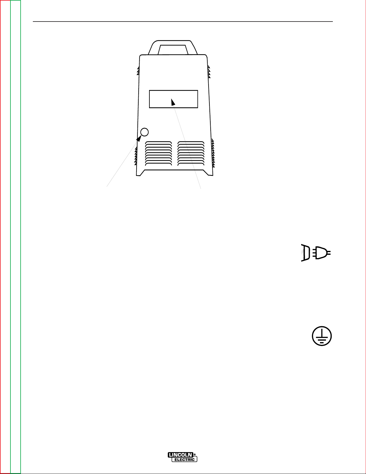
Be sure the voltage, phase, and frequency of the input
supply is as specified on the rating plate. Input Power
supply line entry in provided on the case back of the
machine. See figure A.1 for location of the rating plate.
The Invertec STT II should be connected only by a
qualified electrician. Installation should be made in
accordance with local and national codes. Refer to the
“Technical Specifications” at the beginning of this
section for proper fuse sizes, ground wire, and input
supply power cable sizes.
Some models come from the factory with an input
power cord. If your model does not include the input
power cord install the proper size input cable and
ground cable according to “INPUT CABLE INSTAL-
LATION AND CONNECTION”.
SELECT SUITABLE LOCATION
Locate the machine where there is free circulation of
clean air. Place the machine so that air can freely circulate into the sides and out of the rear of the
machine. Dirt and dust that can be drawn into the
machine should be kept to a minimum. Failure to
observe these precautions can result in excessive
operating temperatures and nuisance shut down of the
Invertec STT II.
This machine carries an enclosure rating of IP21S. It
should not be placed in extremely damp or dirty locations. It should not be exposed to rain or snow.
STACKING
The Invertec STT II cannot be stacked.
TILTING
Place the machine on a secure, level surface otherwise
the unit may topple over.
Read and understand entire Installation
Section before starting installation.
Page 11
INSTALLATION
A-5 A-5
INVERTEC STT
Return to Section TOC Return to Section TOC Return to Section TOC Return to Section TOC
Return to Master TOC Return to Master TOC Return to Master TOC Return to Master TOC
INPUT CABLE INSTALLATION AND CONNECTION
A cable strain relief is provided at the supply line entry
and is designed to accommodate cable diameters of
.310 - 1.070 in. (7.9 - 27.2 mm). On European models
the strain relief is designed to accommodate cable
diameters of .709 - 1.000 in. (18.0 - 25.4 mm). Refer to
“Technical Specifications” at the beginning of this section for the proper input cable sizes. Refer to Figure A.1
and perform the following steps:
1. Remove the wraparound cover of the
Invertec STT II.
2. Feed the input cable through the input cable
entry access hole at the right rear of the
machine.
3. Route the cable through the cable hangers,
located along the lower right inside edge of
the machine, up to the power switch located on
the front panel.
4. Strip away 102 mm (4 in.) of the outer jacket.
Trim fillers and strip conductor jackets to
connect to the power switch.
5. Connect the three phase line conductors to the power switch terminals labeled U, V and W. Tighten
the connections to 3.0 Nm. (27 in.-lb.) torque.
6. Securely tighten the cable strain relief located
on the case back of the machine.
GROUND CONNECTION
1. Connect the ground terminal to earth
ground per National Electrical Code.
2. Replace the wraparound cover of the
Invertec STT II.
CASE BACK
RATING PLATE
INPUT CABLE
ENTRY ACCESS
& CABLE STRAIN RELIEF
FIGURE A.1 CASE BACK
Page 12
A-6
INSTALLATION
A-6
INVERTEC STT II
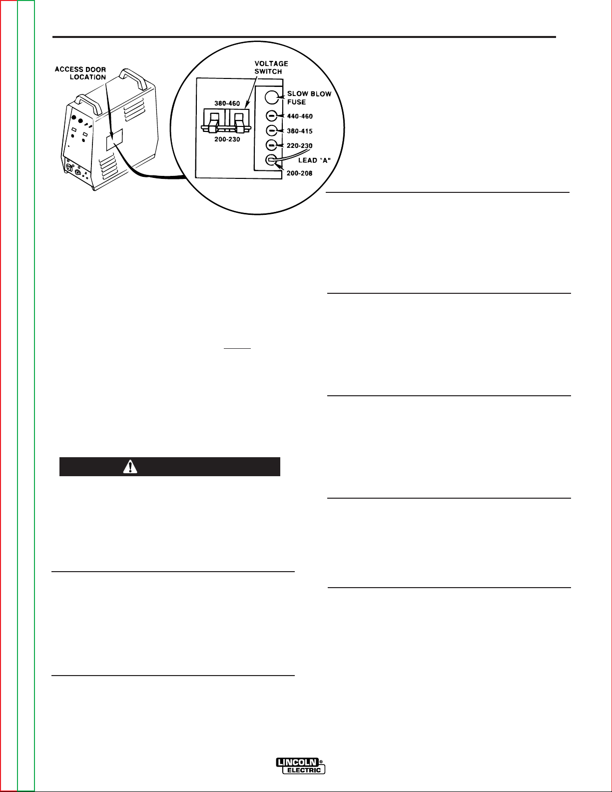
FIGURE A.2 RECONNECT PANEL
I
NPUT VOLTAGE RECONNECT
PROCEDURE
As shipped from the factory, multiple voltage machines
are internally configured for the highest input voltage
(440-460 VAC), for Codes 11092 and below and (380415 VAC), for Codes 11115 and 11116.
1. For Connections to 440 or 460 VAC verify
the internal configurations to the procedures shown below and
refer to Figure A.2.
2. For Connections to 200,208,220,230,380,400 or 415
VAC follow the procedure shown below and refer to figure A.2.
NOTE: Turn main power to the machine OFF
before performing the reconnect procedure.
Failure to do so will result in damage to the
machine. DO NOT switch the reconnect bar with
machine power ON.
------------------------------------------------------------------------
To Operate at Procedure
460 or 440 VAC 1. Open reconnect panel
(Codes 11092 and access door on wraparound.
below) 2. Move input voltage switch
to Voltage = 380 -460V position.
3. Move lead “A” to 440-460
Terminal.
380 or 415 VAC 1. Open reconnect panel
(Codes 11092 and access door on wraparound.
below)
2. Move input voltage switch
to Voltage = 380-460V
position.
3. Move lead “A” to 380-415
Terminal.
380,400 or 415 VAC 1. Open reconnect panel
(Codes 11115 and access door on wraparound.
11116) 2. Move input voltage switch
to Voltage = 380-460V
position.
3. Move lead “A” to 380-415
Terminal.
220 or 230 VAC 1. Open reconnect panel
(Codes 11092 and access door on wraparound.
below) 2. Move input voltage switch
to Voltage = 200 -230V
position.
3. Move lead “A” to 220-230
Terminal.
200 or 208 VAC 1. Open reconnect panel
(Codes 11092 and access door on wraparound.
below) 2. Move input voltage switch
to Voltage = 200 -230V
position.
3. Move lead “A” to 200-208
Terminal.
200 or 208 VAC 1. Open reconnect panel
(Codes 11115 and access door on wrap-around.
11116) 2. Move input voltage switch
to Voltage = 200 -230V
position.
3. Move lead “A” to 200-208
Terminal.
OUTPUT CONNECTIONS
WIRE FEEDER OUTPUT CONNECTIONS
Refer to the Accessories section of this manual for
instructions on connecting a wire feeder to the Invertec
STT II.
The LN-742 or STT-10 wire feeder is the recommended feeder for use with the Invertec STT II.
WARNING
4A
380-415
OR
OR
200-208
*
*
*
(NOT PRESENT ON ALL MODELS)
Return to Section TOC Return to Section TOC Return to Section TOC Return to Section TOC
Return to Master TOC Return to Master TOC Return to Master TOC Return to Master TOC
Page 13

Return to Master TOC Return to Master TOC Return to Master TOC Return to Master TOC
Section B-1 Section B-1
INVERTEC STT
TABLE OF CONTENTS
- OPERATION SECTION -
Operation...............................................................................................................................Section B
Safety Precautions ......................................................................................................................B-2
General Description ....................................................................................................................B-3
Recommended Equipment..........................................................................................................B-3
Operating Controls ......................................................................................................................B-3
Design Features..........................................................................................................................B-3
Welding Capability ......................................................................................................................B-3
Limitations ...................................................................................................................................B-3
Operational Features and Controls.............................................................................................B-4
Welding Operation ......................................................................................................................B-5
Welding Parameters and Guidelines ..........................................................................................B-6
Recommended Settings for STT II..............................................................................................B-7
Page 14
Return to Section TOC Return to Section TOC Return to Section TOC Return to Section TOC
Return to Master TOC Return to Master TOC Return to Master TOC Return to Master TOC
B-2 B-2
INVERTEC STT
ELECTRIC SHOCK
can kill.
• Do not touch electrically live parts
or electrode with skin or wet
clothing.
• Insulate yourself from work and
ground.
• Always wear dry insulating
gloves.
FUMES AND GASES
can be dangerous.
• Keep your head out of fumes.
• Use ventilation or exhaust to
remove fumes from breathing
zone.
WELDING SPARKS
can cause fire or
explosion
• Keep flammable material away.
• Do not weld on containers that
have held combustibles.
ARC RAYS
can burn.
•Wear eye, ear and body
protection.
OPERATING INSTRUCTIONS
Read and understand entire section before
operating machine.
GENERAL WARNINGS
SAFETY PRECAUTIONS
Observe additional Safety Guidelines detailed in the beginning of this manual.
WARNING
OPERATION
Page 15

OPERATION
B-3 B-3
INVERTEC STT
Return to Section TOC Return to Section TOC Return to Section TOC Return to Section TOC
Return to Master TOC Return to Master TOC Return to Master TOC Return to Master TOC
GENERAL DESCRIPTION
The Invertec STT II is a 225-ampere inverter based arc
welding power source specifically designed for the STT
welding process. It is neither a constant current (CC)
nor a constant voltage (CV) machine. It is a power
source that delivers current of a desired wave form and
characteristics that are superior to conventional short
circuiting GMAW. The process is optimized for shortcircuiting GMAW welding.
RECOMMENDED EQUIPMENT
The LN-742 or STT-10 wire feeder is recommended for
use with the STT II. The LN-7 GMA, LN-9 GMA, NA-5,
and NA-5R can all be used with the STT II. However,
these units can only be used to feed wire since these
feeders have no provision for control of the STT output.
OPERATING CONTROLS
The Invertec STT II has the following controls as standard: On/Off switch, Peak Current adjustment,
Background Current adjustment, Hot Start adjustment,
Tailout, and 2 toggle switches; one for wire size selection and one for wire type selection.
DESIGN FEATURES AND ADVANTAGES
• State of the art inverter technology yields high power
efficiency, excellent welding performance, lightweight and compact design.
• Twist-Mate™ output terminals.
• Digital meters for procedure settings are standard.
• Automatic Inductance or Pinch Control.
• Solid state circuitry for extra long component life.
• Current feedback ensures that original procedure
settings all remain constant.
• Arc Sense lead assembly (Electrode and Work),
connects through a 4-pin case front connector.
• Peak Current and Background Current may be
remotely controlled.
• Thermostat and FET over current protector prevent
overheating from overloads, high ambient temperatures, or loss of air flow.
• High temperature Class H insulation.
• Protection circuits and ample safety margins prevent
damage to the solid state components from transient
voltages and high currents.
• Preset welding current capability.
• STT II offers improvements over the previous model.
Approximately 40% increase in deposition rate capability, and a significant increase in travel speed.
WELDING CAPABILITY
The Invertec STT II is rated at 225 amps, 29 volts, at
60% duty cycle on a ten minute basis. It is capable of
higher duty cycles at lower output currents. If the duty
cycle(s) are exceeded, a thermal protector will shut off
the output until the machine cools to a reasonable
operating temperature.
LIMITATIONS
• May not be suitable for use in an environment with
High Frequency present. (“See Machine Grounding
and High Frequency Protection” in the Installation
section of this manual)
• Suitable for indoor use only (IEC IP21S).
Page 16
OPERATION
B-4 B-4
INVERTEC STT
Return to Section TOC Return to Section TOC Return to Section TOC Return to Section TOC
Return to Master TOC Return to Master TOC Return to Master TOC Return to Master TOC
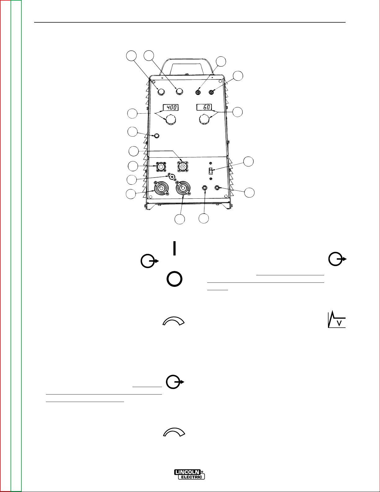
1. POWER SWITCH: Turns output
power ON and OFF. This switch
also controls auxiliary power
available through the 14-pin Wire
Feeder Receptacle.
2A. BACKGROUND CURRENT OUTPUT CONTROL:
The output current is switched to the
Background level at the conclusion of the
preceding Peak Current pulse. This knob
allows preset adjustment of the amplitude
of the background current up to 125
amperes.
2B. BACKGROUND CURRENT DISPLAY METER:
This is a digital meter for displaying the
preset Background Current. This meter
displays in 1 amp increments. This meter
does not indicate the actual welding current, only the preset current.
3A. PEAK CURRENT OUTPUT CONTROL: The
beginning portion of the welding arc is a
pulse of current referred to as Peak
Current. This knob allows preset adjustment of the amplitude of the peak current
up to 450 amperes.
3B. PEAK CURRENT DISPLAY METER: This
is a digital meter for displaying the preset
Peak Current. This meter displays in 1
amp increments. This meter does not indi
cate actual welding current only the preset
current.
4. HOT START CONTROL POTENTIOMETER:
“Hot Start” provides approximately 25% to
50% more current during the initial start of
the weld for improved arc starting and bead
appearance. This control adjusts the duration of this “Hot Start” current. The control range is
from 0 to 10, where 0 corresponds to the zero or no
“Hot Start”, and 10 is maximum for a “Hot Start” lasting for about four (4) seconds.
5. TAILOUT: Alters the current waveform to increase
deposit rate and travel speed. The Minimum setting
sets STT II to the original STT waveform. As tailout
is increased peak and Background current may
need to be reduced to maintain optimum performance.
OPERATIONAL FEATURES AND CONTROLS
All operator controls are located on the case front of the Invertec STT II. Refer to Figure B.1 for locations.
FIGURE B.1 CASE FRONT CONTROLS
4
1
2
3
7
6
8
10
9
11
14
15
12
13
5
ON
OFF
AAV
Page 17

OPERATION
B-5 B-5
INVERTEC STT
Return to Section TOC Return to Section TOC Return to Section TOC Return to Section TOC
Return to Master TOC Return to Master TOC Return to Master TOC Return to Master TOC
6. WIRE SIZE SELECT SWITCH: This toggle switch
selects between electrode diameters of .035” (1 mm)
and smaller or .045” (1.2 mm) and larger. The .035”
(1 mm) position provides improved performance of
smaller diameter wires at higher wire feed speeds.
7. WIRE TYPE SELECT SWITCH: This toggle switch
selects between mild or stainless steel. In the stainless position, the pulse width of the Peak Current is
changed from 1 to 2 ms for better performance for
stainless steel welding.
8. THERMAL SHUT-DOWN INDICATOR: This light
will indicate that either the internal thermostat(s) or the FET over current sensor has
actuated. Machine output will return after
the internal components have returned to normal
operating temperature (if the thermostat(s)
“opened”) or after about 3-7 seconds (if the FET over
current sensor activated).
9.
REMOTE RECEPTACLE: This is a 10 pin MS-type
connector for remote control of Peak Current and
Background Current. Trigger switch connections
are also provided. The presence of the mating connector is automatically sensed, disabling the front panel Peak
and Background Current controls. Refer to “REMOTE CONTROL CONNECTOR” in the ACCESSORIES Section of this
manual for more information.
10. WIRE FEEDER RECEPTACLE: This is 14
pin MS-type connector for the wire feeder
connection. 115 and 42 VAC along with
the trigger switch connections are provided. (Only 42 VAC is available on European models). There are no provisions for voltage control of
the power source by the wire feeder. Refer to the
Accessories section of this manual for wire feeder
connection instructions.
11. ARC SENSE RECEPTACLE:
This is a four pin MStype connector for WORK and ELECTRODE sense
leads. The STT requires a WORK sense and ELECTRODE sense lead for proper operation. The
ELECTRODE sense lead is bolted together with
power source electrode lead at the wire feeder gun
block. The WORK sense lead is furnished with an
“alligator” type clip for connection to the work piece.
Refer to the LN 742 or STT-10 wire feeder connection instructions in the Accessories section of this
manual for proper connection of these leads.
12. 42V AUXILIARY POWER CIRCUIT BREAKER:
The 42 VAC supply is protected from excessive current
draws with a 6 amp circuit breaker. When the
breaker “trips” its button will extend.
Depressing this button will reset the breaker.
13. 115V AUXILIARY POWER CIRCUIT BREAKER
(Not on European Models): The 115 VAC
supply is protected from excessive current
draws with a 6 amp circuit breaker. When
the breaker “trips” its button will extend.
Depressing this button will reset the breaker.
14. WORK TERMINAL: This twist-mate con-
nection is the negative output terminal for
connecting a work cable and clamp to the
workpiece.
15. ELECTRODE TERMINAL: This twist-mate
connection is the positive output terminal
for connecting an electrode cable to the
wire feeder conductor block. Refer to the
Accessories Section for wire feeder connection
instructions.
WELDING OPERATION
Familiarize yourself with the controls on the Invertec
STT II before beginning to weld.
Familiarize yourself with the operating manual for the
wire feeder and the wire feeder controls before beginning to weld.
Set the Wire Size and Wire Type selection switches per
the appropriate wire. Refer to “Operational Features
and Controls” in this section for the function of these
switches.
Page 18
OPERATION
B-6 B-6
INVERTEC STT
Return to Section TOC Return to Section TOC Return to Section TOC Return to Section TOC
Return to Master TOC Return to Master TOC Return to Master TOC Return to Master TOC
WELDING PARAMETERS AND GUIDELINES
The Invertec STT II is neither a constant current (CC)
nor a constant voltage (CV) power source. In general,
wire diameter will be increased one size compared to
conventional (CV) power sources. The larger the wire
diameter the higher the deposition rate (Up to 1/16”).
Wire sizes below .035” are unnecessary for most applications. The Invertec STT II is a current controlled
machine which is capable of changing the electrode
current quickly in order to respond to the instantaneous
requirements of the arc and optimize performance.
By sensing changes in welding current, and hence the
electrode state, the power source will supply varying
output currents to minimize spatter. The Peak and
Background currents are two such current outputs that
can be adjusted.
Wire Feed Speed controls the deposition rate. Peak
Current controls the Arc Length. Background Current
controls the Bead Contour. And Tailout increases
Power in the Arc.
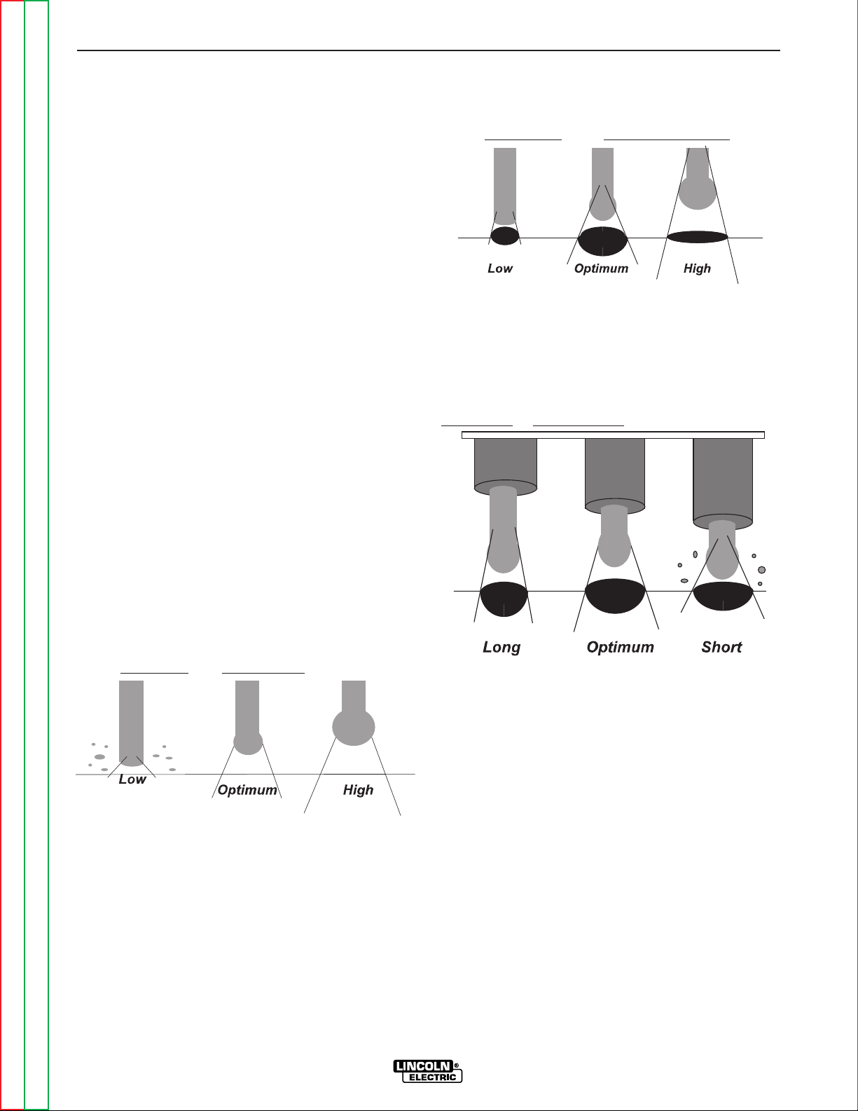
PEAK CURRENT
The Peak Current control acts similar to an “arc pinch”
control. Peak current serves to establish the arc length
and promote good fusion. Higher peak current levels
will cause the arc to broaden momentarily while
increasing the arc length. If set too high, globular type
transfer will occur. Setting this level to low will cause
instability and wire stubbing. In practice, this current
level should be adjusted for minimum spatter and puddle agitation.
Adjust Arc Length
with Peak Current
Note: In 100% CO2shielding gas applications the peak
current level should be set greater than in a corre-
sponding application using a gas blend with a high percentage of Argon. Longer initial arc lengths with 100%
CO2are required to reduce spatter.
BACKGROUND CURRENT
The Background Current provides the control for the
overall heat input to the weld. Adjusting this level too
high will cause a large droplet to form and globular type
transfer to occur resulting in increased spatter.
Adjusting this level to low will cause wire stubbing and
also poor wetting of the weld metal. This is similar to a
low voltage setting on a standard CV machine
Adjust Bead Shape
using Background Current
Note: Background Current levels for applications using
100% CO2
is less than similar procedures involving gas
blends with high percentages of Argon. This is a result
of the greater heat generated in the 100% CO
2 arc.
(100% CO2 is 35 volts/cm and 100% Argon is 20
volts/cm. 75% Argon, 25% CO
2 is about 24 volts/cm.
Contact
Tip to W
ork Distance
HOT START
The Hot Start control can be set to enhance establishing the arc and provide the capability of increasing the
heat at the start of the weld to compensate for a cold
work piece. Hot start adjusts the time that additional
current is applied during the starting of the arc. Refer to
“Operational Features and Controls” in this section
for a description of this control.
TAILOUT
The tail out provides additional heat without the molten
droplet becoming too large. Increase as necessary to
add “Heat” to the arc without increasing arc length.
(This will allow for faster travel speeds and produce
improved wetting). As tailout is increased, the peal
and/or background current is usually reduced.
WELDING ARC PERFORMANCE
For optimum spatter reduction, the arc should be concentrated on the puddle.
Page 19
Return to Section TOC Return to Section TOC Return to Section TOC Return to Section TOC
Return to Master TOC Return to Master TOC Return to Master TOC Return to Master TOC
OPERATION
B-7 B-7
INVERTEC STT
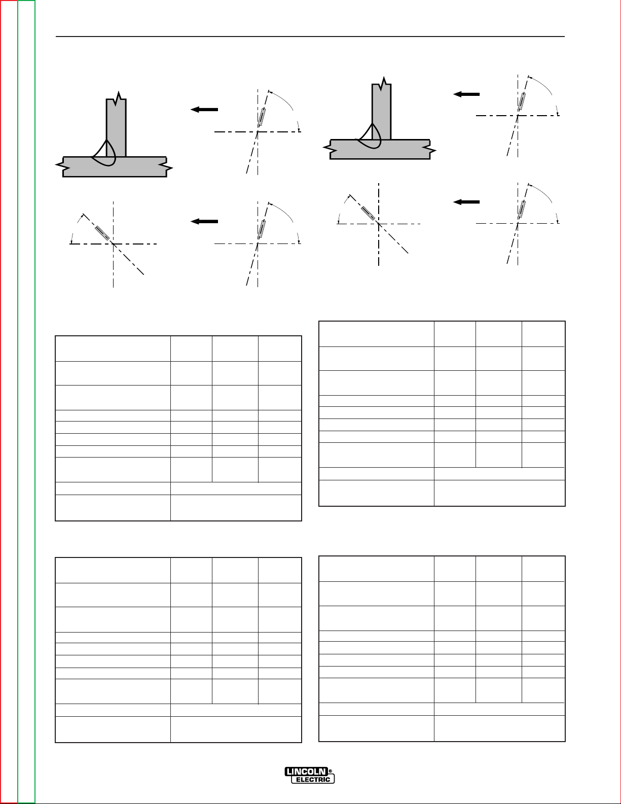
WELDING PROCEDURES FOR STT II -
(Steel) Horizontal Fillet (See Table B.1 and B.2)
Table B.1
100% CO
2
Gas Shield (Set for Steel Mode)
Table B.2
75% CO
2
- 25% Ar Gas Shield (Set for Steel Mode)
(Stainless Steel) Horizontal Fillet
(See Table B.3 and B.4)
Table B.3
90% He, 7.5% Ar, 2.5% CO
2
Gas Shield (Set for Steel Mode)
Table B.4
98% Ar, 2% O
2
Gas Shield (Set for Stainless Steel Mode)
45°
END VIEW
75°
FRONT VIEW
DIRECTION
OF
TRAVEL
75°
TOP VIEW
DIRECTION
OF
TRAVEL
Plate Thickness “ (mm) 20 ga 14 ga 10 ga
(0.9) (2.0) (3.25)
Electrode size “ (mm) 0.035 0.045 0.045
(0.9) (1.1) (1.1)
WFS “/min (m/min) 100 100 170
(2.5) (2.5) (4.2)
Peak Current 220 260 280
Background Current 30 40 65
Tailout setting 3 7 5
Average Amperage 60 105 120
Travel Speed “/min 12 12 12
(m/min) (0.3) (0.3) (0.3)
Gas Flow cfh (L/min) 25 (12)
Electrical Stickout “ 1/4 - 3/8
(mm) (6.4 - 10)
Plate Thickness “ (mm) 20 ga 14 ga 10 ga
(0.9) (2.0) (3.25)
Electrode size “ (mm) 0.035 0.045 0.045
(0.9) (1.1) (1.1)
WFS “/min (m/min) 100 100 120
(2.5) (2.5) (3.0)
Peak Current 225 270 310
Background Current 40 65 70
Tailout setting 8 4 6
Average Amperage 70 110 130
Travel Speed “/min 12 12 12
(m/min) (0.3) (0.3) (0.3)
Gas Flow cfh (L/min) 25 (12)
Electrical Stickout “ 1/4 - 3/8
(mm) (6.4 - 10)
45°
END VIEW
75°
FRONT VIEW
DIRECTION
OF
TRAVEL
75°
TOP VIEW
DIRECTION
OF
TRAVEL
Plate Thickness “ (mm) 20 ga 14 ga 10 ga
(0.9) (2.0) (3.25)
Electrode size “ (mm) 0.035 0.045 0.045
(0.9) (1.1) (1.1)
WFS “/min (m/min) 100 130 170
(2.5) (3.3) (4.2)
Peak Current 165 210 250
Background Current 35 60 85
Tailout setting 7 7 4
Average Amperage 40 95 120
Travel Speed “/min 12 16 16
(m/min) (0.3) (0.4) (0.4)
Gas Flow cfh (L/min) 25 (12)
Electrical Stickout “ 1/4 - 3/8
(mm) (6.4 - 10)
Plate Thickness “ (mm) 20 ga 14 ga 10 ga
(0.9) (2.0) (3.25)
Electrode size “ (mm) 0.035 0.045 0.045
(0.9) (1.1) (1.1)
WFS “/min (m/min) 100 130 170
(2.5) (3.3) (4.2)
Peak Current 145 190 280
Background Current 45 95 95
Tailout setting 7 8 7
Average Amperage 60 120 150
Travel Speed “/min 12 12 12
(m/min) (0.3) (0.3) (0.3)
Gas Flow cfh (L/min) 25 (12)
Electrical Stickout “ 1/4 - 3/8
(mm) (6.4 - 10)
Page 20

NOTES
B-8 B-8
INVERTEC STT
Return to Section TOC Return to Section TOC Return to Section TOC Return to Section TOC
Return to Master TOC Return to Master TOC Return to Master TOC Return to Master TOC
Page 21

Return to Master TOC Return to Master TOC Return to Master TOC Return to Master TOC
TABLE OF CONTENTS
- ACCESSORIES -
Accessories...........................................................................................................................Section C
Options/Accessories ...................................................................................................................C-2
LN-742 Wire Feeder Connection Instructions.............................................................................C-3
Connection Diagram ...................................................................................................................C-4
Section C-1 Section C-1
INVERTEC STT
Page 22
ACCESSORIES
C-2 C-2
INVERTEC STT
Return to Section TOC Return to Section TOC Return to Section TOC Return to Section TOC
Return to Master TOC Return to Master TOC Return to Master TOC Return to Master TOC
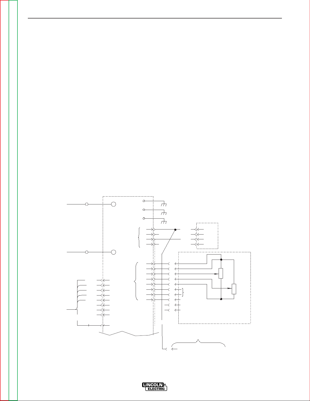
STT control board to accept PEAK and BACKGROUND inputs on this connector rather than from
the front panel controls. If this short is removed, the
front panel controls will be active. By adding a switch
between pins “J” and “B” a “LOCAL/REMOTE” control switch can be created. (Switch open for “local”
and closed for “remote”)
3. For robotic control of the PEAK CURRENT, a 0 to
+10 volt DC signal is applied between pins “A” and
“G” with + applied to pin “G”. The BACKGROUND
CURRENT is controlled with a similar signal applied
between pins “A” and “C” with + applied to pin “C”.
In this application pins “J” and “B” must be shorted
as described in 2 above.
NOTE: These analog signals should be isolated
from the robot circuitry to prevent interference.
4. The trigger switch is connected between pins “D”
and “F”. These connections are in parallel with the
trigger switch from the wire feeder.
5. The digital meters for PEAK and BACKGROUND
currents will show preset values in both local and
remote operation.
OPTIONS / ACCESSORIES
K940 SENSE LEADS: These leads are used to accu-
rately sense arc voltage. One set is required for each
STT II power source. A 10 ft and 25 ft set are provided as standard with the machine. Additional sets are
available in 10 ft (K940-10), 25 ft (K940-25) and 50 ft
(K940-50) lengths.
K942-1 REMOTE CONTROL: Allows remote adjustment of Peak and Background Current settings.
REMOTE RECEPTACLE (For optional remote interface,
Connection to the STT-10 Wire Feeder or Robotic Control)
1. The 10 pin MS connector labeled “Remote Control”
located on the front panel of the STT is used for
remote control of the power source. Control for the
PEAK (PB pot) and BACKGROUND (BG pot) current along with the trigger switch is provide through
this connector.
2. Refer to figure C.1 below for details about the
remote receptacle (J38). Note that pins “J” and “B”
are shorted together This “short circuit” tells the
+ ARC
- ARC
1
2
3
4
VOLTAGE
SENSE
CONNECTION
J19
290
291
(+)
(-)
J
B
C
G
A
D
F
H
E
I
TRIGGER
GND
BG
PB
10K
10K
OPTIONAL
REMOTE
INTERFACE
223
7
J38
33C
1
2
3
4
J37
8
6
1
5
8
4
3
2
212C
43A
212B
32C
3
1
2
10
9
12
4
11
J38
REMOTE
PROTECTION BOARD
PORTION OF G3136 WIRING DIAGRAM
REFER TO ACTUAL DIAGRAM PASTED INSIDE YOUR MACHINE
N
ELECTRODE SENSE LEAD
290A
J39
WIRE
FEEDER
Page 23
ACCESSORIES
C-3 C-3
INVERTEC STT
Return to Section TOC Return to Section TOC Return to Section TOC Return to Section TOC
Return to Master TOC Return to Master TOC Return to Master TOC Return to Master TOC
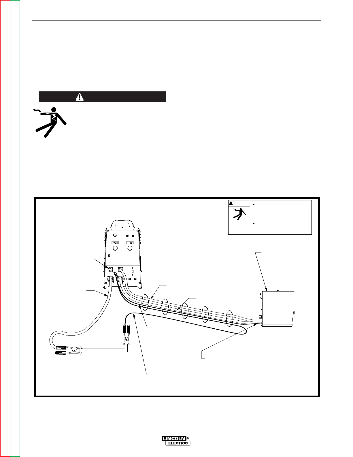
LN-742 or STT-10 WIRE FEEDER
CONNECTION INSTRUCTIONS
The LN-742 or STT-10 is the recommended wire feeder for use with the Invertec STT II. Refer to the LN742 or STT-10 Operator Manual for Wire Feed
Operation. Refer to Figure C.2 or C.3 and follow the
instructions below to connect the LN-742 or STT-10.
1. Turn the Invertec STT II power off.
2. Connect the ARC SENSE LEAD MS connector to
the mating connector on STT II front panel.
3. Connect the electrode lead (Twist-Mate) to (+) output terminal on STT II.
4. Connect the other end of electrode lead (Step #3)
and the ARC SENSE LEAD (lead with ring lug, step
#2) together to the gun block on the LN 742.
5. Connect work lead between STT (-) terminal and the
work piece.
6. Connect the ARC SENSE LEAD “WORK” (lead with
alligator clip) to work piece.
NOTE: For best welding performance make this
connection as close as possible to the
welding arc.
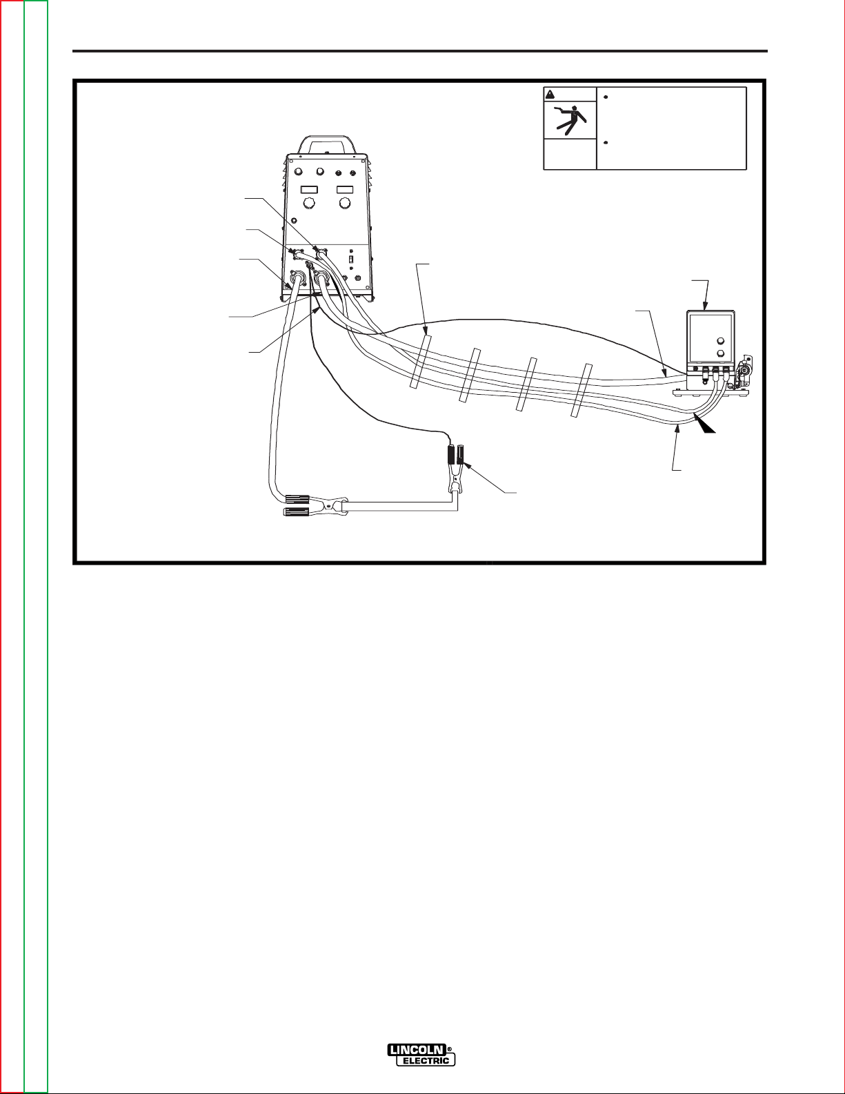
7. Connect the wire feeder control cable between the
LN-742 or STT-10 and the 14-pin Wire Feeder
Receptacle on the STT II. For the STT-10 Wire
Feeder: Connect the second wire feeder control
cable between the STT-10 and the 10-pin Remote
Receptacle on the STT II.
M17657
ARC SENSE LEAD
’ELECT"
CONNECT ELECTRODE LEAD AND "ELECT"
ARC SENSE LEAD TOGETHER TO ELECTRODE
TERMINAL OF WIRE FEEDER.
ELECTRODE LEAD
Only qualified persons should install,
use or service this machine.
WIRE FEEDER
LN 742
LN7 GMA
LN9 GMA
NA5R
NA5
WARNING
ELECTRIC
SHOCK
CAN KILL
Turn off input power to the Welding
Power source using the disconnnect
switch at the fuse box before
connecting the wire feeder.
REMOTE RECEPTACLE
WORK
WORK LEAD
CONTROL, ELECTRODE, ARC SENSE "ELECT"
AND ARC SENSE "WORK" CABLES SHOULD
BE TAPED TOGETHER.
WIRE FEEDER
CONTROL CABLE
ARC SENSE LEAD "WORK"
(SHOULD BE LOCATED
AS CLOSE AS POSSIBLE
TO THE WELDING ARC.)
CRM after 6-10-96
FIGURE C.2 LN-742 to STT II CONNECTION
WARNING
ELECTRIC SHOCK can kill.
• Only qualified personnel should perform
this installation.
•Turn the input power OFF at the disconnect switch or fuse box before connecting
the wire feeder
Page 24
C-4 C-4
INVERTEC STT
Return to Section TOC Return to Section TOC Return to Section TOC Return to Section TOC
Return to Master TOC Return to Master TOC Return to Master TOC Return to Master TOC
ACCESSORIES
CONNECTION DIAGRAM - INVERTEC STT II
4-9-99
M17657-3
CABLES AND LEADS SHOULD
ELECTRODE LEAD
BE TAPED TOGETHER.
WORK
(SHOULD BE LOCATED
AS CLOSE AS POSSIBLE
FEEDER
REMOTE
REMOTE
ELECTRODE LEAD
TO THE WELDING ARC)
WORK LEAD
WIRE FEEDER
WIRE FEEDER CONTACT
ELECTRODE SENSE LEAD
IS BOLTED TOGETHER WITH
ELECTRODE LEAD ON THE
BLOCK
STT-10
WIRE FEEDER
WARNING
Turn off input power to the Welding
Power source using the disconnnect
switch at the fuse box before
connecting the wire feeder.
Only qualified persons should install,
ELECTRIC
use or service this machine.
SHOCK
CAN KILL
WIRE
ARC SENSE LEAD "WORK"
FIGURE C.3 STT-10 to STT II CONNECTION
Page 25

Return to Master TOC Return to Master TOC Return to Master TOC Return to Master TOC
Section D-1 Section D-1
INVERTEC STT
TABLE OF CONTENTS
-MAINTENANCE-
Maintenance .........................................................................................................................Section D
Input Filter Capacitor Discharge Procedure................................................................................D-2
Preventive Maintenance .............................................................................................................D-3
Major Component Locations.......................................................................................................D-4
Page 26
MAINTENANCE
D-2 D-2
INVERTEC STT
Return to Section TOC Return to Section TOC Return to Section TOC Return to Section TOC
Return to Master TOC Return to Master TOC Return to Master TOC Return to Master TOC
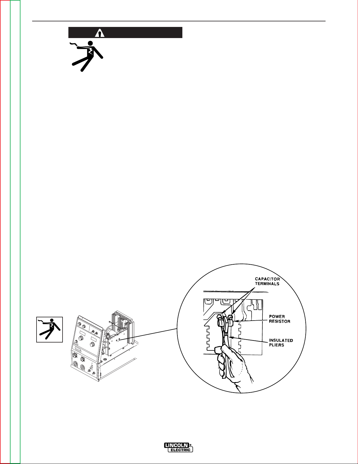
WARNING
Failure to follow this
capacitor discharge procedure can result in electric
shock.
INPUT FILTER CAPACITOR
DISCHARGE PROCEDURE
1. Turn off input power or disconnect input
power lines.
2. Remove hex head screws from side and
top of machine and remove wrap-around
machine cover.
3. Be careful not to make contact with the
capacitor terminals that are located in the
center of the Switch Boards.
4. Obtain a high resistance and high
wattage resistor (25-1000 ohms and 25
watts minimum). This resistor is not supplied with machine. NEVER USE A
SHORTING STRAP FOR THIS PROCEDURE.
5. Locate the two capacitor terminals (large
hex head cap screws) shown in Figure
D.1.
6. Use safety glasses, electrically insulated
gloves and insulated pliers. Hold body of
the resistor and connect resistor leads
across the two capacitor terminals. Hold
resistor in place for 10 seconds. DO NOT
TOUCH CAPACITOR TERMINALS WITH
YOUR BARE HANDS.
7. Repeat discharge procedure for capaci-
tor on other side of machine.
8. Check voltage across terminals of all
capacitors with a DC voltmeter. Polarity
of capacitor terminals is marked on PC
board above terminals. Voltage should be
zero. If any voltage remains, repeat this
capacitor discharge procedure.
FIGURE D.1 — LOCATION OF INPUT FILTER CAPACITOR TERMINALS.
Page 27

MAINTENANCE
D-3 D-3
INVERTEC STT
Return to Section TOC Return to Section TOC Return to Section TOC Return to Section TOC
Return to Master TOC Return to Master TOC Return to Master TOC Return to Master TOC
PREVENTIVE MAINTENANCE
1. Perform the following preventive maintenance procedures at least once every six
months. It is good practice to keep a preventive maintenance record; a record tag
attached to the machine works best.
2. Remove the machine wraparound cover
and perform the input filter capacitor discharge procedure (detailed at the beginning of this chapter).
3. Clean the inside of the machine with a
low pressure airstream. Be sure to clean
the following components thoroughly.
• Power Switch, Driver, Protection, and
Control printed circuit boards
• Power Switch
• Main Transformer
• Input Rectifier
• Heat Sink Fins
• Input Filter Capacitors
• Output Terminals
• Lower base compartment
4. Examine capacitors for leakage or oozing.
Replace if needed.
5. Examine wraparound cover for dents or
breakage. Repair as needed. Cover must
be kept in good condition to assure high
voltage parts are protected and correct
spacings are maintained.
6. Check electrical ground continuity. Using
an ohmmeter, measure resistance
between either output stud and an unpainted surface of the machine case. Meter
reading should be 500,000 ohms or more.
If meter reading is less than 500,000
ohms, check for electrical components that
are not properly insulated from the case.
Correct insulation if needed.
7. Replace machine cover and screws.
Page 28
Return to Section TOC Return to Section TOC Return to Section TOC Return to Section TOC
Return to Master TOC Return to Master TOC Return to Master TOC Return to Master TOC
MAINTENANCE
D-4 D-4
INVERTEC STT
12
4
17
5
6
9
8
7
10
16
15
13
18
14
19
11
1
3
2
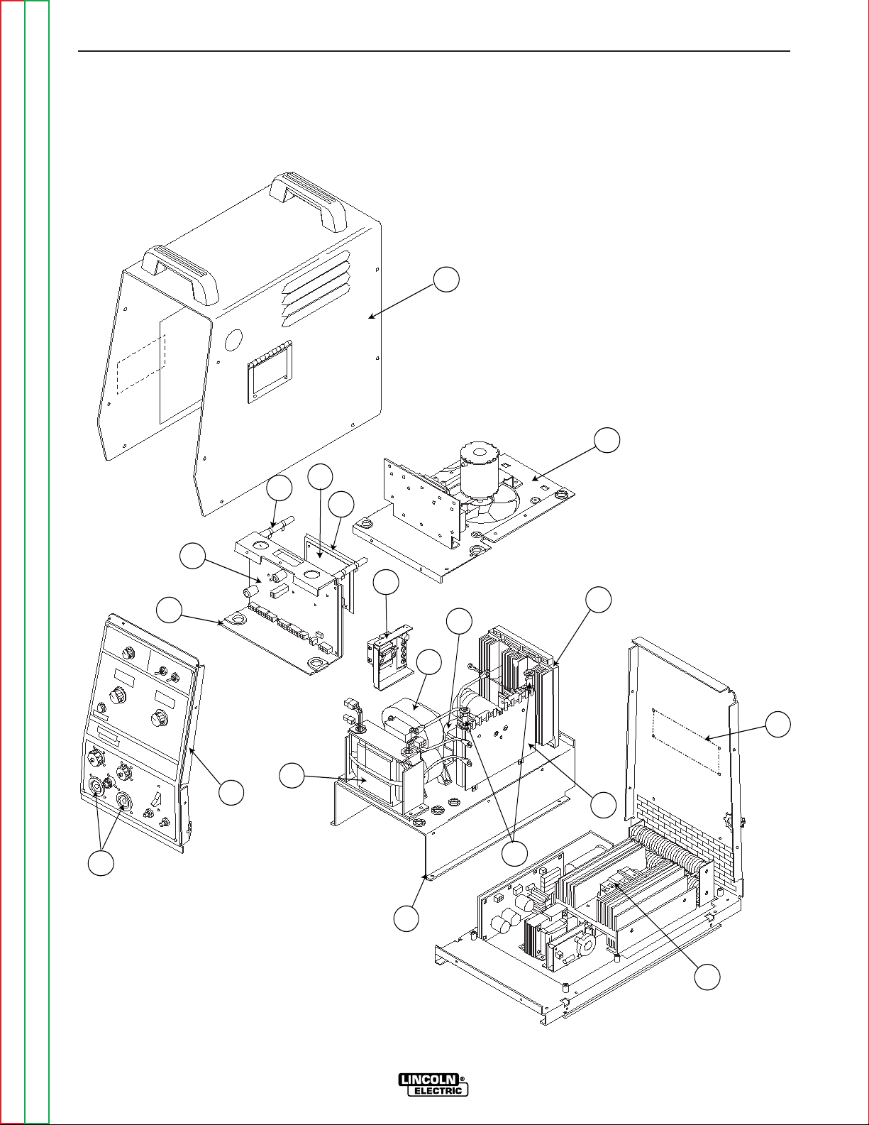
FIGURE D.2 – MAJOR COMPONENT LOCATIONS
1. BASE ASSEMBLY
2. REAR NAMEPLATE
3. RESISTORS
4. FAN SHROUD ASSEMBLY
5. PROTECTION PC BOARD
6. DRIVER PC BOARD
7. CONTROL BOX
8. CONTROL PC BOARD
9. BLEEDER RESISTORS
10. RECONNECT PANEL
11. IGBT OR DARLINGTON MODULE
12. WRAPAROUND ASSEMBLY
13. CASE FRONT ASSEMBLY
14. OUTPUT TERMINALS
15. OUTPUT CHOKE ASSEMBLY
16. TRANSFORMER ASSEMBLY
17. OUTPUT RECTIFIER ASSEMBLY
18. AUXILIARY TRANSFORMER
19. FET HEAT SINK ASSEMBLY
Page 29
Return to Master TOC Return to Master TOC Return to Master TOC Return to Master TOC
Section E-1 Section E-1
INVERTEC STT
Theory of Operation .............................................................................................................Section E
General Description ...............................................................................................................E-2
Input Voltage..........................................................................................................................E-2
Reconnect, Protection Board, Rectification and Precharge ..................................................E-3
Switch Boards........................................................................................................................E-4
Main Transformer, Output Rectification and Choke...............................................................E-5
Control Board, IGBT Drive and Module.................................................................................E-6
Power Board ..........................................................................................................................E-7
Remote Protection Board ......................................................................................................E-7
Field Effect Transistor (FET) Operation.................................................................................E-8
Pulse Width Modulation.........................................................................................................E-9
Minimum Output ..............................................................................................................E-9
Maximum Output .............................................................................................................E-9
Protective Circuits................................................................................................................E-10
Overload Protection.......................................................................................................E-10
Thermal Protection ........................................................................................................E-10
TABLE OF CONTENTS
-THEORY OF OPERATION SECTION-
POSITIVE
OUTPUT
TERMINAL
TERMINAL
OUTPUT
NEGATIVE
CONTROL BOARD
IGBT
DRIVER
BOARD
P
O
W
E
R
B
O
A
R
D
FAN
TRANS
T1
TRANS
T4
S
W
I
T
C
H
B
O
A
R
D
S
W
I
T
C
H
B
O
A
R
D
R
E
C
O
N
N
E
C
T
P
R
O
T
E
C
T
I
O
N
INPUT
RECTIFIER
LINE
SWITCH
CR1
CR2
B
O
A
R
D
D
R
I
V
E
R
B
O
A
R
D
PRE -
CHARGE
PRE -
CHARGE
CHOKE
CURRENT
SENSOR
IGBT
MODULE
1 OHM
PEAK
CURRENT
METER
BACK-
METER
PEAK
CURRENT
CONTROL
BACK-
CONTROL
HOT
START
CONTROL
WIRE
SIZE
SWITCH
WIRE
TYPE
SWITCH
VOLTAGE
SENSING
RECEPTACLE
REMOTE
CONTROL
RECEPTACLE
WIRE
RECEPTACL
E
FEEDER
R
E
M
O
T
E
P
R
O
T
E
C
T
I
O
N
B
O
A
R
D
CURRENT
TRANS
T3
MAIN
TRANSFORMER
T2
115
VAC
18
VAC
2
4
V
A
C
"A"
LEAD
15VDC
T
H
E
R
M
O
S
T
A
T
CURRENT FEEDBACK
42VAC
VOLTAGE FEEDBACK
10VAC AND 6VAC
D
R
I
V
E
S
I
G
N
A
L
36VAC
GUN TRIGGER
LESS THAN 1VDC
PWM SIGNAL
PULSE TRANSFORMER SIGNAL
GROUND
GROUND
FET
FET
FET
FET
CAP
CAP
TAILOUT
CONTROL
(STT II ONLY)
FIGURE E.1 – INVERTEC STT
Page 30

GENERAL DESCRIPTION
The Invertec STT is a 225 ampere, inverter based, arc
welding power supply specifically designed for the
Surface Tension Transfer (STT) welding process. It
cannot be classified as either a constant current (CC)
or a constant voltage (CV) machine. The STT produces current of a desired waveform to reduce spatter
and fumes. The STT process is optimized for short circuit GMAW welding only.
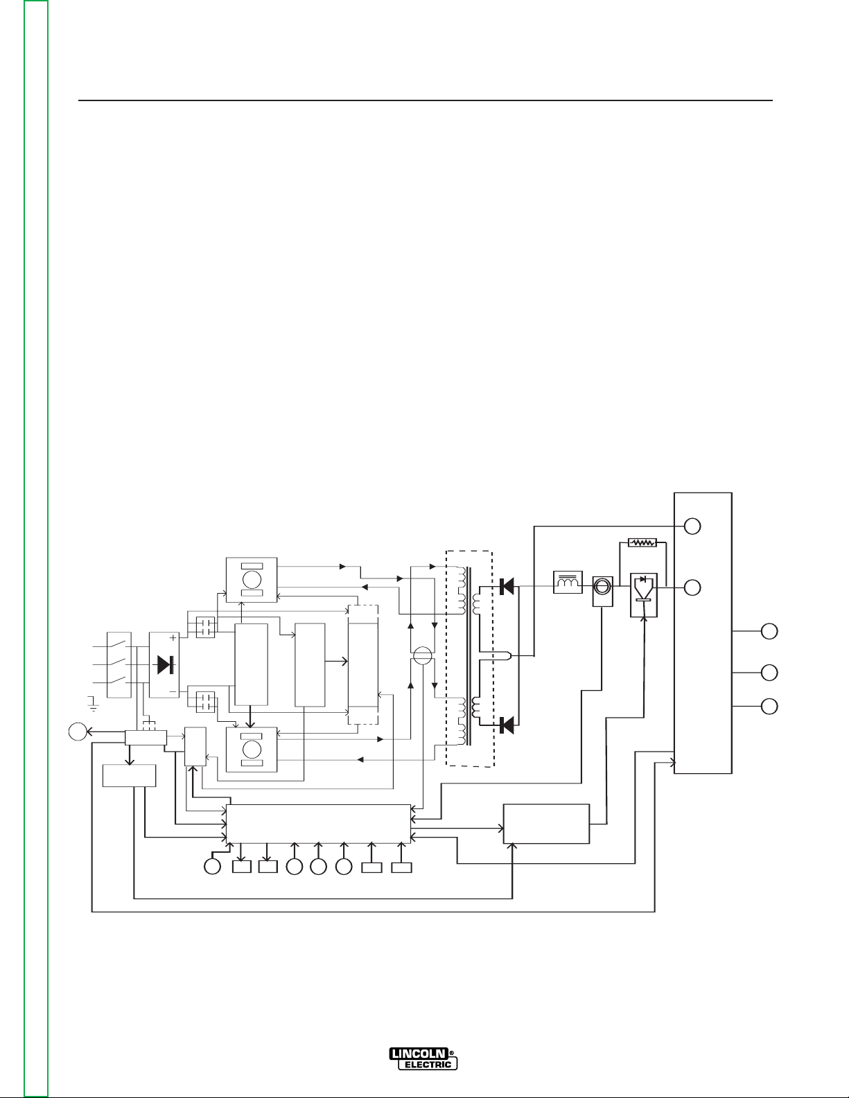
INPUT VOLTAGE
The Invertec STT can be connected for a variety of
three-phase voltages. The initial input power is applied
to the STT through a line switch located on the front of
the machine. The AC input voltage is applied to the
input rectifier and the T1 auxiliary transformer. The T1
transformer develops the appropriate AC voltages to
operate the cooling fan, the power and control boards.
The T1 transformer also supplies primary voltage to the
T4 auxiliary transformer as well as 42 VAC to an external wire feeder. The T4 transformer supplies power to
the IGBT drive board and the control board.
THEORY OF OPERATION
E-2 E-2
INVERTEC STT
Return to Section TOC Return to Section TOC Return to Section TOC Return to Section TOC
Return to Master TOC Return to Master TOC Return to Master TOC Return to Master TOC
FIGURE E.2 – INPUT VOLTAGE
NOTE: Unshaded areas of Block Logic Diagram are the subject of discussion.
POSITIVE
OUTPUT
TERMINAL
TERMINAL
OUTPUT
NEGATIVE
CONTROL BOARD
IGBT
DRIVER
BOARD
P
O
W
E
R
B
O
A
R
D
FAN
TRANS
T1
TRANS
T4
S
W
I
T
C
H
B
O
A
R
D
S
W
I
T
C
H
B
O
A
R
D
R
E
C
O
N
N
E
C
T
P
R
O
T
E
C
T
I
O
N
INPUT
RECTIFIER
LINE
SWITCH
CR1
CR2
B
O
A
R
D
D
R
I
V
E
R
B
O
A
R
D
PRE -
CHARGE
PRE -
CHARGE
CHOKE
CURRENT
SENSOR
IGBT
MODULE
1 OHM
PEAK
CURRENT
METER
BACK-
METER
PEAK
CURRENT
CONTROL
BACK-
CONTROL
HOT
START
CONTROL
WIRE
SIZE
SWITCH
WIRE
TYPE
SWITCH
VOLTAGE
SENSING
RECEPTACLE
REMOTE
CONTROL
RECEPTACLE
WIRE
RECEPTACL
E
FEEDER
R
E
M
O
T
E
P
R
O
T
E
C
T
I
O
N
B
O
A
R
D
CURRENT
TRANS
T3
MAIN
TRANSFORMER
T2
115
VAC
18
VAC
2
4
V
A
C
"A"
LEAD
15VDC
T
H
E
R
M
O
S
T
A
T
CURRENT FEEDBACK
42VAC
VOLTAGE FEEDBACK
10VAC AND 6VAC
D
R
I
V
E
S
I
G
N
A
L
36VAC
GUN TRIGGER
LESS THAN 1VDC
PWM SIGNAL
PULSE TRANSFORMER SIGNAL
GROUND
GROUND
FET
FET
FET
FET
CAP
CAP
TAILOUT
CONTROL
(STT II ONLY)
Page 31

RECONNECT, PROTECTION
BOARD, RECTIFICATION AND
PRECHARGE
The reconnect panel allows the user to switch to low or
high input voltage to match the input line voltage. The
AC input voltage is rectified and applied to the driver
board. The driver board contains precharging circuitry
for safe charging of the input filter capacitors. Once the
capacitors are precharged, the input relays are energized, connecting full input power to the input filter
capacitors. The protection board monitors the capacitors for voltage balance and/or overvoltage and will deenergize the input relays and precharge circuitry if
either occurs. The machine output will be disabled.
THEORY OF OPERATION
E-3 E-3
INVERTEC STT
Return to Section TOC Return to Section TOC Return to Section TOC Return to Section TOC
Return to Master TOC Return to Master TOC Return to Master TOC Return to Master TOC
NOTE: Unshaded areas of Block Logic Diagram are the subject of discussion.
FIGURE E.3 – RECONNECT, PROTECTION BOARD, RECTIFICATION AND PRECHARGE
POSITIVE
OUTPUT
TERMINAL
TERMINAL
OUTPUT
NEGATIVE
CONTROL BOARD
IGBT
DRIVER
BOARD
P
O
W
E
R
B
O
A
R
D
FAN
TRANS
T1
TRANS
T4
S
W
I
T
C
H
B
O
A
R
D
S
W
I
T
C
H
B
O
A
R
D
R
E
C
O
N
N
E
C
T
P
R
O
T
E
C
T
I
O
N
INPUT
RECTIFIER
LINE
SWITCH
CR1
CR2
B
O
A
R
D
D
R
I
V
E
R
B
O
A
R
D
PRE -
CHARGE
PRE -
CHARGE
CHOKE
CURRENT
SENSOR
IGBT
MODULE
1 OHM
PEAK
CURRENT
METER
BACK-
METER
PEAK
CURRENT
CONTROL
BACK-
CONTROL
HOT
START
CONTROL
WIRE
SIZE
SWITCH
WIRE
TYPE
SWITCH
VOLTAGE
SENSING
RECEPTACLE
REMOTE
CONTROL
RECEPTACLE
WIRE
RECEPTACL
E
FEEDER
R
E
M
O
T
E
P
R
O
T
E
C
T
I
O
N
B
O
A
R
D
CURRENT
TRANS
T3
MAIN
TRANSFORMER
T2
115
VAC
18
VAC
2
4
V
A
C
"A"
LEAD
15VDC
T
H
E
R
M
O
S
T
A
T
CURRENT FEEDBACK
42VAC
VOLTAGE FEEDBACK
10VAC AND 6VAC
D
R
I
V
E
S
I
G
N
A
L
36VAC
GUN TRIGGER
LESS THAN 1VDC
PWM SIGNAL
PULSE TRANSFORMER SIGNAL
GROUND
GROUND
FET
FET
FET
FET
CAP
CAP
TAILOUT
CONTROL
(STT II ONLY)
Page 32

Return to Section TOC Return to Section TOC Return to Section TOC Return to Section TOC
Return to Master TOC Return to Master TOC Return to Master TOC Return to Master TOC
THEORY OF OPERATION
E-4 E-4
INVERTEC STT
NOTE: Unshaded areas of Block Logic Diagram are the subject of discussion.
FIGURE E.4 – SWITCH BOARDS
SWITCH BOARDS
There are two switch boards in the Invertec STT, each
containing an input filter capacitor. The capacitors are
connected in parallel when the machine is connected
for "low" input voltage. The capacitors are connected
in series when the reconnect switch is configured for
"high" input voltage. When the capacitors are fully
charged, they act as power supplies for the switch
boards. The switch boards contain the Field Effect
Transistors (FETs) which, when switched on, supply
the main transformer primary windings with DC current
flow. See Field Effect Transistor (FET) Operation
discussion and diagrams. See Figure E.4.
POSITIVE
OUTPUT
TERMINAL
TERMINAL
OUTPUT
NEGATIVE
CONTROL BOARD
IGBT
DRIVER
BOARD
P
O
W
E
R
B
O
A
R
D
FAN
TRANS
T1
TRANS
T4
S
W
I
T
C
H
B
O
A
R
D
S
W
I
T
C
H
B
O
A
R
D
R
E
C
O
N
N
E
C
T
P
R
O
T
E
C
T
I
O
N
INPUT
RECTIFIER
LINE
SWITCH
CR1
CR2
B
O
A
R
D
D
R
I
V
E
R
B
O
A
R
D
PRE -
CHARGE
PRE -
CHARGE
CHOKE
CURRENT
SENSOR
IGBT
MODULE
1 OHM
PEAK
CURRENT
METER
BACK-
METER
PEAK
CURRENT
CONTROL
BACK-
CONTROL
HOT
START
CONTROL
WIRE
SIZE
SWITCH
WIRE
TYPE
SWITCH
VOLTAGE
SENSING
RECEPTACLE
REMOTE
CONTROL
RECEPTACLE
WIRE
RECEPTACL
E
FEEDER
R
E
M
O
T
E
P
R
O
T
E
C
T
I
O
N
B
O
A
R
D
CURRENT
TRANS
T3
MAIN
TRANSFORMER
T2
115
VAC
18
VAC
2
4
V
A
C
"A"
LEAD
15VDC
T
H
E
R
M
O
S
T
A
T
CURRENT FEEDBACK
42VAC
VOLTAGE FEEDBACK
10VAC AND 6VAC
D
R
I
V
E
S
I
G
N
A
L
36VAC
GUN TRIGGER
LESS THAN 1VDC
PWM SIGNAL
PULSE TRANSFORMER SIGNAL
GROUND
GROUND
FET
FET
FET
FET
CAP
CAP
TAILOUT
CONTROL
(STT II ONLY)
Page 33

Return to Section TOC Return to Section TOC Return to Section TOC Return to Section TOC
Return to Master TOC Return to Master TOC Return to Master TOC Return to Master TOC
THEORY OF OPERATION
E-5 E-5
INVERTEC STT
FIGURE E.5 – MAIN TRANSFORMER, OUTPUT RECTIFICATION AND CHOKE
MAIN TRANSFORMER, OUTPUT
RECTIFICATION AND CHOKE
Each switch board works as a switch pair. Each board
feeds a separate, oppositely wound primary winding of
the main transformer. The opposite directions of current flow through the main transformer primary and the
offset timing of the switch boards induce an AC square
wave output signal at the secondary of the main transformer.
The DC current flow through each primary winding,
which is monitored by the current transformer T3, is
redirected or "clamped" back to each respective input
capacitor when the FETs are turned off. This is needed due to the inductance of the transformer primary
windings. The cross coupling of the primaries along
with the clamping action of the diode maintain capacitor balance when they are connected in the series (high
voltage) input configuration.
The firing of both switch board pairs occurs during
halves of 50 microsecond intervals, creating a constant
20 KHZ output.
The AC output from the main transformer secondary is
rectified to a DC output and is applied through a stabilizer output choke, current sensor, IGBT module and
remote protection board to the output terminals.
NOTE: Unshaded areas of Block Logic Diagram are the subject of discussion.
POSITIVE
OUTPUT
TERMINAL
TERMINAL
OUTPUT
NEGATIVE
CONTROL BOARD
IGBT
DRIVER
BOARD
P
O
W
E
R
B
O
A
R
D
FAN
TRANS
T1
TRANS
T4
S
W
I
T
C
H
B
O
A
R
D
S
W
I
T
C
H
B
O
A
R
D
R
E
C
O
N
N
E
C
T
P
R
O
T
E
C
T
I
O
N
INPUT
RECTIFIER
LINE
SWITCH
CR1
CR2
B
O
A
R
D
D
R
I
V
E
R
B
O
A
R
D
PRE -
CHARGE
PRE -
CHARGE
CHOKE
CURRENT
SENSOR
IGBT
MODULE
1 OHM
PEAK
CURRENT
METER
BACK-
METER
PEAK
CURRENT
CONTROL
BACK-
CONTROL
HOT
START
CONTROL
WIRE
SIZE
SWITCH
WIRE
TYPE
SWITCH
VOLTAGE
SENSING
RECEPTACLE
REMOTE
CONTROL
RECEPTACLE
WIRE
RECEPTACL
E
FEEDER
R
E
M
O
T
E
P
R
O
T
E
C
T
I
O
N
B
O
A
R
D
CURRENT
TRANS
T3
MAIN
TRANSFORMER
T2
115
VAC
18
VAC
2
4
V
A
C
"A"
LEAD
15VDC
T
H
E
R
M
O
S
T
A
T
CURRENT FEEDBACK
42VAC
VOLTAGE FEEDBACK
10VAC AND 6VAC
D
R
I
V
E
S
I
G
N
A
L
36VAC
GUN TRIGGER
LESS THAN 1VDC
PWM SIGNAL
PULSE TRANSFORMER SIGNAL
GROUND
GROUND
FET
FET
FET
FET
CAP
CAP
TAILOUT
CONTROL
(STT II ONLY)
Page 34

Return to Section TOC Return to Section TOC Return to Section TOC Return to Section TOC
Return to Master TOC Return to Master TOC Return to Master TOC Return to Master TOC
THEORY OF OPERATION
E-6 E-6
INVERTEC STT
FIGURE E.6 – CONTROL BOARD, IGBT DRIVE AND MODULE
CONTROL BOARD, IGBT DRIVE
AND MODULE
The control board monitors the directives of the various
controls and compares these commands to the current
and voltage feedback information received from the
current sensor and voltage sensing receptacle. This
data is processed and the suitable PWM signal is sent
to the power board. (See Pulse Width Modulation
discussion).
The control board also determines when the IGBT
module should be switched OFF to reduce weld spatter and fumes. The appropriate signal is sent to the
IGBT drive board which then applies, or removes, the
gate drive signal to the IGBT module. When the IGBT
module is in the OFF state, the welding current must
pass through the one ohm resistance. This reduces
the current and, subsequently, spatter and fumes.
NOTE: Unshaded areas of Block Logic Diagram are the subject of discussion.
POSITIVE
OUTPUT
TERMINAL
TERMINAL
OUTPUT
NEGATIVE
CONTROL BOARD
IGBT
DRIVER
BOARD
P
O
W
E
R
B
O
A
R
D
FAN
TRANS
T1
TRANS
T4
S
W
I
T
C
H
B
O
A
R
D
S
W
I
T
C
H
B
O
A
R
D
R
E
C
O
N
N
E
C
T
P
R
O
T
E
C
T
I
O
N
INPUT
RECTIFIER
LINE
SWITCH
CR1
CR2
B
O
A
R
D
D
R
I
V
E
R
B
O
A
R
D
PRE -
CHARGE
PRE -
CHARGE
CHOKE
CURRENT
SENSOR
IGBT
MODULE
1 OHM
PEAK
CURRENT
METER
BACK-
METER
PEAK
CURRENT
CONTROL
BACK-
CONTROL
HOT
START
CONTROL
WIRE
SIZE
SWITCH
WIRE
TYPE
SWITCH
VOLTAGE
SENSING
RECEPTACLE
REMOTE
CONTROL
RECEPTACLE
WIRE
RECEPTACL
E
FEEDER
R
E
M
O
T
E
P
R
O
T
E
C
T
I
O
N
B
O
A
R
D
CURRENT
TRANS
T3
MAIN
TRANSFORMER
T2
115
VAC
18
VAC
2
4
V
A
C
"A"
LEAD
15VDC
T
H
E
R
M
O
S
T
A
T
CURRENT FEEDBACK
42VAC
VOLTAGE FEEDBACK
10VAC AND 6VAC
D
R
I
V
E
S
I
G
N
A
L
36VAC
GUN TRIGGER
LESS THAN 1VDC
PWM SIGNAL
PULSE TRANSFORMER SIGNAL
GROUND
GROUND
FET
FET
FET
FET
CAP
CAP
TAILOUT
CONTROL
(STT II ONLY)
Page 35

Return to Section TOC Return to Section TOC Return to Section TOC Return to Section TOC
Return to Master TOC Return to Master TOC Return to Master TOC Return to Master TOC
THEORY OF OPERATION
E-7 E-7
INVERTEC STT
FIGURE E.7 – POWER BOARD AND REMOTE PROTECTION BOARD
POWER BOARD
The power board creates a pulse transformer drive signal, which is derived from the PWM signal received
from the control board. See Pulse Width Modulation
discussion. This drive signal is applied to the primary
winding of the pulse transformer, which is located on
the driver board. The pulse transformer secondary
windings generate the proper gate pulse for the switch
board FETs. See Field Effect Transistor (FET)
Operation.
The power board supplies a 15VDC supply voltage for
the control board and also powers the input relays
(CR1 and CR2).
REMOTE PROTECTION BOARD
The remote protection board provides noise suppression and by-pass filtering to protect the internal circuitry of the STT machine.
NOTE: Unshaded areas of Block Logic Diagram are the subject of discussion.
POSITIVE
OUTPUT
TERMINAL
TERMINAL
OUTPUT
NEGATIVE
CONTROL BOARD
IGBT
DRIVER
BOARD
P
O
W
E
R
B
O
A
R
D
FAN
TRANS
T1
TRANS
T4
S
W
I
T
C
H
B
O
A
R
D
S
W
I
T
C
H
B
O
A
R
D
R
E
C
O
N
N
E
C
T
P
R
O
T
E
C
T
I
O
N
INPUT
RECTIFIER
LINE
SWITCH
CR1
CR2
B
O
A
R
D
D
R
I
V
E
R
B
O
A
R
D
PRE -
CHARGE
PRE -
CHARGE
CHOKE
CURRENT
SENSOR
IGBT
MODULE
1 OHM
PEAK
CURRENT
METER
BACK-
METER
PEAK
CURRENT
CONTROL
BACK-
CONTROL
HOT
START
CONTROL
WIRE
SIZE
SWITCH
WIRE
TYPE
SWITCH
VOLTAGE
SENSING
RECEPTACLE
REMOTE
CONTROL
RECEPTACLE
WIRE
RECEPTACL
E
FEEDER
R
E
M
O
T
E
P
R
O
T
E
C
T
I
O
N
B
O
A
R
D
CURRENT
TRANS
T3
MAIN
TRANSFORMER
T2
115
VAC
18
VAC
2
4
V
A
C
"A"
LEAD
15VDC
T
H
E
R
M
O
S
T
A
T
CURRENT FEEDBACK
42VAC
VOLTAGE FEEDBACK
10VAC AND 6VAC
D
R
I
V
E
S
I
G
N
A
L
36VAC
GUN TRIGGER
LESS THAN 1VDC
PWM SIGNAL
PULSE TRANSFORMER SIGNAL
GROUND
GROUND
FET
FET
FET
FET
CAP
CAP
TAILOUT
CONTROL
(STT II ONLY)
Page 36

FIELD EFFECT TRANSISTOR (FET)
OPERATION
An FET is a type of transistor. FETs are semiconductors well suited for high-frequency switching.
Drawing A above shows an FET in a passive mode.
There is no gate signal, zero volts relative to the source
and, therefore, no current flow. The drain terminal of
the FET may be connected to a voltage supply; but
since there is no conduction, the circuit will not supply
current to downstream components connected to the
source. The circuit is turned off like a light switch in the
OFF position.
Drawing B above shows the FET in an active mode.
When the gate signal, a positive DC voltage relative to
the source, is applied to the gate terminal of the FET, it
is capable of conducting current. A voltage supply connected to the drain terminal will allow the FET to conduct and henceforth supply current to downstream
components. Current will flow through the conducting
FET to downstream components as long as the gate
signal is present. This is similar to turning on a light
switch.
THEORY OF OPERATIONS
E-8 E-8
INVERTEC STT
Return to Section TOC Return to Section TOC Return to Section TOC Return to Section TOC
Return to Master TOC Return to Master TOC Return to Master TOC Return to Master TOC
SOURCE
TERMINAL
GATE
TERMINAL
DRAIN
TERMINAL
DRAIN (N)
N CHANNELSUBSTRATE (P)
SOURCE (N)
(0 VOLTS)
GATE
TERMINAL
(+ 6 VOLTS)
DRAIN (N)
ELECTRONS
SOURCE (N)
B. ACTIVE
A. PASSIVE
FIGURE E-8 – FIELD EFFECT TRANSISTOR OPERATION
Page 37

PULSE WIDTH MODULATION
The term PULSE WIDTH MODULATION is used to
describe how much time is devoted to conduction in
the positive and negative portions of the cycle.
Changing the pulse width is known as MODULATION.
Pulse Width Modulation (PWM) is the varying of the
pulse width over the allowed range of a cycle to affect
the output of the machine.
MINIMUM OUTPUT
By controlling the duration of the gate signal, the FET
is turned on and off for different durations during a
cycle. The top drawing above shows the minimum output signal possible over a 50-microsecond time period.
The positive portion of the signal represents one FET
group
1
conducting for 1 microsecond. The negative
portion is the other FET group
1
. The dwell time (off
time) is 48 microseconds (both FET groups off). Since
only 2 microseconds of the 50-microsecond time period is devoted to conducting, the output power is minimized.
MAXIMUM OUTPUT
By holding the gate signals on for 24 microseconds
each and allowing only 2 microseconds of dwell time
(off time) during the 50-microsecond cycle, the output
is maximized. The darkened area under the top curve
can be compared to the area under the bottom curve.
The more dark area under the curve, the more power
is present.
THEORY OF OPERATION
E-9 E-9
INVERTEC STT
Return to Section TOC Return to Section TOC Return to Section TOC Return to Section TOC
Return to Master TOC Return to Master TOC Return to Master TOC Return to Master TOC
MINIMUM OUTPUT
MAXIMUM OUTPUT
24
50
2
48
50
sec
sec
sec
sec
sec
sec
sec
24
sec
FIGURE E-9 – TYPICAL FET OUTPUTS
1
A FET group consists of the sets of FET modules grouped onto
one switch board.
Page 38

PROTECTIVE CIRCUITS
Protective circuits are designed into the Invertec
machine to sense trouble and shut down the machine
before the trouble damages the internal machine components. Both overload and thermal protection circuits
are included.
OVERLOAD PROTECTION
The machine is electrically protected from producing
abnormally high output currents due to short electrode
“stick-out” or the nozzle shorting to the work. Should
the output current exceed 500 amps, an electronic protection circuit will reduce the current to zero amps.
Five seconds after the “short” is removed the Invertec
STT will produce normal output.
A protection circuit is included to monitor the voltage
across input filter capacitors. In the event that the
capacitor voltage is too high, the protection circuit will
prevent output. The protection circuit may prevent output, if any of these circumstances occur:
1. Capacitor conditioning is required
(Required if machine has been off for prolonged
periods of time.)
2. Line surges over 500 VAC
3. Internal Component damage
4. Improper connections
THERMAL PROTECTION
Thermostats protect the machine from excessive operating temperatures. Excessive temperatures may be
caused by a lack of cooling air or operating the
machine beyond the duty cycle and output rating. If
excessive operating temperature should occur, the
thermostat will prevent output voltage or current. The
meter will remain on during this time. (In addition, the
yellow thermo LED will light.)
Thermostats are self-resetting once the machine cools
sufficiently. If the thermostat shutdown was caused by
excessive output or duty cycle and the fan is operating
normally, the Power Switch may be left on and the
reset should occur within a 15-minute period. If the fan
is not turning or the air intake louvers were obstructed,
then the power must be switched off for 15 minutes in
order to reset. The fan problem or air obstruction must
also be corrected.
THEORY OF OPERATION
E-10 E-10
INVERTEC STT
Return to Section TOC Return to Section TOC Return to Section TOC Return to Section TOC
Return to Master TOC Return to Master TOC Return to Master TOC Return to Master TOC
Page 39

Return to Master TOC Return to Master TOC Return to Master TOC Return to Master TOC
Section F-1 Section F-1
INVERTEC STT
Troubleshooting & Repair Section ................................................................................Section F
How to Use Troubleshooting Guide.......................................................................................F-2
PC Board Troubleshooting Procedures .................................................................................F-3
Troubleshooting Guide .................................................................................................F4 - F-12
Te st Procedures...................................................................................................................F-13
T1 Auxiliary Transformer Test ........................................................................................F-13
T4 Auxiliary Transformer Test ........................................................................................F-19
Input Rectifier Test.........................................................................................................F-25
Capacitor Balance Test .................................................................................................F-29
Switch Board Test..........................................................................................................F-33
Snubber Resistors Test .................................................................................................F-37
Power Board Test ..........................................................................................................F-41
Protection Board Test ....................................................................................................F-45
Trigger Circuit Test ........................................................................................................F-49
Replacement Procedures ....................................................................................................F-53
IGBT Module Removal and Replacement.....................................................................F-53
Switch Board Replacement ...........................................................................................F-59
Capacitor Removal and Replacement Procedure.........................................................F-65
Output Rectifier Removal and Replacement.................................................................F-73
Retest After Repair...............................................................................................................F-77
TABLE OF CONTENTS
TROUBLESHOOTING & REPAIR SECTION
Page 40

Return to Section TOC Return to Section TOC Return to Section TOC Return to Section TOC
Return to Master TOC Return to Master TOC Return to Master TOC Return to Master TOC
HOW TO USE TROUBLESHOOTING GUIDE
Service and repair should be performed by only Lincoln Electric Factory Trained Personnel.
Unauthorized repairs performed on this equipment may result in danger to the technician and machine
operator and will invalidate your factory warranty. For your safety and to avoid Electrical Shock, please
observe all safety notes and precautions detailed throughout this manual.
TROUBLESHOOTING & REPAIR
F-2 F-2
INVERTEC STT
This Troubleshooting Guide is provided to help
you locate and repair possible machine malfunctions. Simply follow the three-step procedure listed below.
Step 1. LOCATE PROBLEM (SYMPTOM). Look
under the column labeled “PROBLEM (SYMPTOMS). This column describes possible symptoms that the machine may exhibit. Find the listing that best describes the symptom that the
machine is exhibiting. Symptoms are grouped
into two main categories: Output Problems, and
Welding Problems.
Step 2. PERFORM EXTERNAL TESTS.
The
second column, labeled “POSSIBLE AREAS OF
MISADJUSTMENT(S)”, lists the obvious external
possibilities that may contribute to the machine
symptom. Perform these tests/checks in the order
listed. In general, these tests can be conducted
without removing the case wrap-around cover.
Step 3. PERFORM COMPONENT TESTS. The
last column, labeled “Recommended Course of
Action” lists the most likely components that may
have failed in your machine. It also specifies the
appropriate test procedure to verify that the subject component is either good or bad. If there are
a number of possible components, check the
components in the order listed to eliminate one
possibility at a time until you locate the cause of
your problem.
All of the referenced test procedures referred to in
the Troubleshooting Guide are described in detail
at the end of this chapter. Refer to the
Troubleshooting and Repair Table of Contents to
locate each specific Test Procedure. All of the
referred to test points, components, terminal
strips, etc., can be found on the referenced electrical wiring diagrams and schematics. Refer to
the Electrical Diagrams Section Table of
Contents to locate the appropriate diagram.
WARNING
If for any reason you do not understand the test procedures or are unable to perform the test/repairs
safely, contact the Lincoln Electric Service Department for electrical troubleshooting assistance before
you proceed. Call
1-888-935-3877
.
OSCILLOSCOPE WARNING
Do not use oscilloscopes and other test equipment which are powered by 115 VAC. This equipment
should not be used with inverter-type machines, such as Invertec STT. There are high voltages present, which are “floating” off case ground (floating ground). Connecting the ground lead of a test probe
(which may be connected to the case of the test equipment) to a high voltage potential presents a shock
hazard as well as the possibility of damage to the equipment in question.
WARNING
CAUTION
Page 41

ELECTRIC SHOCK can kill.
Have an electrician install and service
this equipment. Turn the machine OFF
before working on equipment. Do not
touch electrically hot parts.
Sometimes machine failures appear to be due to PC
board failures. These problems can sometimes be
traced to poor electrical connections. To avoid problems when troubleshooting and replacing PC boards,
please use the following procedure:
1. Determine to the best of your technical ability that
the PC board is the most likely component causing
the failure symptom.
2. Check for loose connections at the PC board to
assure that the PC board is properly connected.
3. If the problem persists, replace the suspect PC
board using standard practices to avoid static electrical damage and electrical shock. Read the warning inside the static resistant bag and perform the
following procedures:
PC Board can be damaged by
static electricity.
• Remove your body’s static charge
before opening the static-shielding
bag. Wear an anti-static wrist
strap. For safety, use a 1 Meg
ohm resistive cord connected to a
grounded part of the equipment
frame.
• If you don’t have a wrist strap,
touch an unpainted, grounded,
part of the equipment frame. Keep
touching the frame to prevent static build-up. Be sure not to touch
any electrically live parts at the
same time.
• Tools which come in contact with the PC Board must
be either conductive, anti-static or static-dissipative.
• Remove the PC Board from the static-shielding bag
and place it directly into the equipment. Don’t set the
PC Board on or near paper, plastic or cloth which
could have a static charge. If the PC Board can’t be
installed immediately, put it back in the static-shielding
bag.
• If the PC Board uses protective shorting jumpers,
don’t remove them until installation is complete.
• If you return a PC Board to The Lincoln Electric
Company for credit, it must be in the static-shielding
bag. This will prevent further damage and allow proper failure analysis.
4. Test the machine to determine if the failure symp-
tom has been corrected by the replacement PC
board.
NOTE: Allow the machine to heat up so that all electri-
cal components can reach their operating temperature.
5. Remove the replacement PC board and substitute
it with the original PC board to recreate the original
problem.
a. If the original problem does not reappear
by substituting the original board, then the
PC board was not the problem. Continue
to look for bad connections in the control
wiring harness, junction blocks, and terminal strips.
b. If the original problem is recreated by the
substitution of the original board, then the
PC board was the problem. Reinstall the
replacement PC board and test the
machine.
6. Always indicate that this procedure was followed
when warranty reports are to be submitted.
NOTE: Following this procedure and writing on the
warranty report, “INSTALLED AND
SWITCHED PC BOARDS TO VERIFY PROBLEM,” will help avoid denial of legitimate PC
board warranty claims.
TROUBLESHOOTING & REPAIR
F-3 F-3
INVERTEC STT
Return to Section TOC Return to Section TOC Return to Section TOC Return to Section TOC
Return to Master TOC Return to Master TOC Return to Master TOC Return to Master TOC
PC BOARD TROUBLESHOOTING PROCEDURES
WARNING
ATTENTION
Static-Sensitive
Devices
Handle only at
Static-Safe
Workstations
Reusable
Container
Do Not Destroy
Page 42

Return to Section TOC Return to Section TOC Return to Section TOC Return to Section TOC
Return to Master TOC Return to Master TOC Return to Master TOC Return to Master TOC
TROUBLESHOOTING & REPAIR
F-4 F-4
INVERTEC STT
Observe Safety Guidelines TROUBLESHOOTING GUIDE
detailed in the beginning of this manual.
CAUTION
If for any reason you do not understand the test procedures or are unable to perform the test/repairs safely, contact the Lincoln Electric Service Department for electrical troubleshooting assistance before you proceed.
Call
1-888-935-3877
.
PROBLEMS
(SYMPTOMS)
POSSIBLE AREAS OF
MISADJUSTMENT(S)
RECOMMENDED
COURSE OF ACTION
OUTPUT PROBLEMS
Major physical or electrical damage is evident.
1. Contact your local Lincoln
Authorized Field Service
Facility.
1.
Contact the Lincoln Electric
Service Department,
1-888-935-
3877
.
Machine has no open circuit voltage. Wire feeds OK.
1. Check the control cable
between the feeder and the
STT unit. Make sure the #2 and
#4 leads are intact.
2. Put a jumper wire between Pins
"C" and "D" on the 14 pin
amphenol. If normal open circuit voltage (85VDC) is
restored, the problem is in the
feeder control cable or the wire
feeder.
3. Make sure the reconnect switch
S7 is in the correct position for
the three-phase input voltage
being applied.
Do not switch reconnect switch
with input power applied to
machine.
1. Perform the T1 Auxiliary
Transformer Test.
2. Perform the T4 Auxiliary
Transformer Test.
3. Perform the Power Board Test.
4. Perform the Trigger Circuit
Test.
5. Perform Capacitor Balance
Test.
6. Perform the Protection Board
Test.
7. Perform the Switch Board
Test.
8. Check for loose or broken connections on the heavy current
carrying conductors (i.e., main
transformer, choke, output
diodes, IGBT module and output terminals).
9. The control PC board may be
faulty. Replace.
CAUTION
Page 43

Return to Section TOC Return to Section TOC Return to Section TOC Return to Section TOC
Return to Master TOC Return to Master TOC Return to Master TOC Return to Master TOC
TROUBLESHOOTING & REPAIR
F-5 F-5
INVERTEC STT
TROUBLESHOOTING GUIDE Observe Safety Guidelines
detailed in the beginning of this manual.
CAUTION
If for any reason you do not understand the test procedures or are unable to perform the test/repairs safely, contact the Lincoln Electric Service Department for electrical troubleshooting assistance before you proceed.
Call
1-888-935-3877
.
PROBLEMS
(SYMPTOMS)
POSSIBLE AREAS OF
MISADJUSTMENT(S)
RECOMMENDED
COURSE OF ACTION
OUTPUT PROBLEMS
Machine has no welding output (no open circuit voltage), and the wire feeder does not feed wire when the gun trigger is pulled.
1. The 42VAC circuit breaker CB1
may be tripped. Reset if necessary.
2. Check the 4 amp slow blow fuse
located on the reconnect panel.
Replace if faulty.
3. Put a jumper between pins "A"
and "C" on the 5 pin amphenol
located on the LN-742 wire
feeder. If wire feeds, check the
gun trigger. Repair or replace if
necessary.
4. Check for the presence of
42VAC at pins "K" and "I" on the
14 pin amphenol. If the 42VAC
is present and the feeder does
not work, the problem is in the
feeder control cable or the wire
feeder.
1. If 42VAC is NOT present at pins
"K" and "I" on the 14 pin amphenol, perform the T1 Auxiliary
Transformer Test.
2. Check leads #43 and #212C for
loose or faulty connections
between the T1 auxiliary transformer and the remote protection board. See the Wiring
Diagram. Also check the continuity through the remote protection board to the 14 pin amphenol. See the Remote Protection
Board Schematic.
Page 44

Return to Section TOC Return to Section TOC Return to Section TOC Return to Section TOC
Return to Master TOC Return to Master TOC Return to Master TOC Return to Master TOC
TROUBLESHOOTING & REPAIR
F-6 F-6
INVERTEC STT
Observe Safety Guidelines
TROUBLESHOOTING GUIDE
detailed in the beginning of this manual.
CAUTION
If for any reason you do not understand the test procedures or are unable to perform the test/repairs safely, contact the Lincoln Electric Service Department for electrical troubleshooting assistance before you proceed.
Call
1-888-935-3877
.
PROBLEMS
(SYMPTOMS)
POSSIBLE AREAS OF
MISADJUSTMENT(S)
RECOMMENDED
COURSE OF ACTION
OUTPUT PROBLEMS
Machine is dead - no output - no fan - no display.
1. The power switch must be in the
"ON" position.
2. Check the input voltage. Make
sure all three phases are
applied to the machine.
3. With input power removed,
check that the input voltage setup switch and jumper "A" (the
reconnect auxiliary jumper) are
in the proper position for the
input voltage being used.
4. With input power removed,
check the continuity of the 4
amp slow blow fuse located on
the reconnect panel.
1. The input power switch (S1)
may be faulty. Check or
replace.
2. Perform the T1 Auxiliary
Transformer Test.
No output or reduced output the first time power is applied to the machine.
1. Check input voltages, fuses and
input voltage reconnect procedures. See the Installation
section.
2. If high input voltage (380VAC or
higher) is applied, the capacitors may need conditioning. Let
the "unloaded" machine idle for
30 minutes.
1. Contact the Lincoln Electric
Service Department.
1-888-935-
3877
.
Page 45

Return to Section TOC Return to Section TOC Return to Section TOC Return to Section TOC
Return to Master TOC Return to Master TOC Return to Master TOC Return to Master TOC
TROUBLESHOOTING & REPAIR
F-7 F-7
INVERTEC STT
TROUBLESHOOTING GUIDE Observe Safety Guidelines
detailed in the beginning of this manual.
CAUTION
If for any reason you do not understand the test procedures or are unable to perform the test/repairs safely, contact the Lincoln Electric Service Department for electrical troubleshooting assistance before you proceed.
Call
1-888-935-3877
.
PROBLEMS
(SYMPTOMS)
POSSIBLE AREAS OF
MISADJUSTMENT(S)
RECOMMENDED
COURSE OF ACTION
OUTPUT PROBLEMS
No output. Main fuses are open, indicating excessive current draw.
1. With the input power removed,
inspect input leads for possible
shorts or grounds or misconnections.
2. Install new fuses and reapply
power. If fuses open again,
contact your local Lincoln
Authorized Field Service
Facility.
1. Check the input power switch
(S1) and the reconnect switch
for "shorted" or "grounded"
wires or connections.
2. Perform the Input Rectifier
Test.
3. Perform the Switch Board
Test.
Machine loses output when gun trigger is pulled or arc is struck. Machine output returns after a few seconds and trigger is pulled again. The thermal indicator light is lit.
1. The overcurrent sensor is activated, indicating that too much
output current is being drawn
from the machine. Reduce
welding current demands or
remove the "fault" in welding
cables.
2. Make sure that the gun tip is not
"shorted" to the work surface
and that the proper welding procedures are being used.
1. The current sensor may be
faulty.
2. The control PC board may be
faulty.
Page 46

Return to Section TOC Return to Section TOC Return to Section TOC Return to Section TOC
Return to Master TOC Return to Master TOC Return to Master TOC Return to Master TOC
F-8 F-8
INVERTEC STT
TROUBLESHOOTING & REPAIR
TROUBLESHOOTING GUIDE Observe Safety Guidelines
detailed in the beginning of this manual.
CAUTION
If for any reason you do not understand the test procedures or are unable to perform the test/repairs safely, contact the Lincoln Electric Service Department for electrical troubleshooting assistance before you proceed.
Call
1-888-935-3877
.
PROBLEMS
(SYMPTOMS)
POSSIBLE AREAS OF
MISADJUSTMENT(S)
RECOMMENDED
COURSE OF ACTION
OUTPUT PROBLEMS
Machine loses output while welding. The thermal indicator light is
lit. Normal welding output returns
after about 10 minutes.
1. Check to make sure the fan is
running and operating correctly.
2. Welding application may
exceed recommended duty
cycle.
3. Dirt and dust may have clogged
the cooling channels. Blow out
the unit with clean, dry compressed air.
4. Air intake and exhaust louvers
may be blocked due to inadequate clearance around the
machine.
1. The IGBT heat sink thermostat
or fan thermostat may be defec-
tive. Check or replace.
Page 47

Return to Section TOC Return to Section TOC Return to Section TOC Return to Section TOC
Return to Master TOC Return to Master TOC Return to Master TOC Return to Master TOC
TROUBLESHOOTING & REPAIR
F-9 F-9
INVERTEC STT
Observe Safety Guidelines
TROUBLESHOOTING GUIDE
detailed in the beginning of this manual.
CAUTION
If for any reason you do not understand the test procedures or are unable to perform the test/repairs safely, contact the Lincoln Electric Service Department for electrical troubleshooting assistance before you proceed.
Call
1-888-935-3877
.
PROBLEMS
(SYMPTOMS)
POSSIBLE AREAS OF
MISADJUSTMENT(S)
RECOMMENDED
COURSE OF ACTION
WELDING PROBLEMS
Porosity in the weld. 1. Make sure the gas type and
flow rate is correct for the procedure being used. Shield the
work from excessive outside air
currents.
2. Check the gun and nozzle for
leaks or obstructions.
3. Make certain the machine and
wire feed settings are correct for
the process.
1. Contact the Lincoln Electric
Service Department.
1-888-935-
3877
.
Page 48

Return to Section TOC Return to Section TOC Return to Section TOC Return to Section TOC
Return to Master TOC Return to Master TOC Return to Master TOC Return to Master TOC
TROUBLESHOOTING & REPAIR
F-10 F-10
INVERTEC STT
TROUBLESHOOTING GUIDE Observe Safety Guidelines
detailed in the beginning of this manual.
CAUTION
If for any reason you do not understand the test procedures or are unable to perform the test/repairs safely, contact the Lincoln Electric Service Department for electrical troubleshooting assistance before you proceed.
Call
1-888-935-3877
.
PROBLEMS
(SYMPTOMS)
POSSIBLE AREAS OF
MISADJUSTMENT(S)
RECOMMENDED
COURSE OF ACTION
WELDING PROBLEMS
Weld bead appears "cold." 1. One or more of the machine
settings may be wrong. Check
the Background, Peak Current,
Tailout (STT II Only), and Wire
Speed controls for proper settings. Adjust for optimum welding performance.
2. Make sure the Wire Type and
Wire Size switches are in the
correct position for the electrode wire being used.
1. Check for the correct open circuit voltage (approximately
85VDC). If the correct open circuit voltage IS present, the
Background control (R12) or
the Peak Current (R11) and
associated wiring may be faulty.
See the Wiring Diagram. The
control PC board may be faulty.
Also check for loose or faulty
connections on the heavy current carrying conductors (i.e.,
main transformer, choke, output
diodes, IGBT module and output terminals).
2. If the correct open circuit voltage is NOT present, perform
the Switch Board Test.
3. The output diodes may be
faulty. Check or replace if necessary.
4. The driver PC board and or
control PC board may be faulty.
5. The IGBT module may be
faulty. Check or replace.
Page 49

Return to Section TOC Return to Section TOC Return to Section TOC Return to Section TOC
Return to Master TOC Return to Master TOC Return to Master TOC Return to Master TOC
TROUBLESHOOTING & REPAIR
F-11 F-11
INVERTEC STT
Observe Safety Guidelines
TROUBLESHOOTING GUIDE
detailed in the beginning of this manual.
CAUTION
If for any reason you do not understand the test procedures or are unable to perform the test/repairs safely, contact the Lincoln Electric Service Department for electrical troubleshooting assistance before you proceed.
Call
1-888-935-3877
.
PROBLEMS
(SYMPTOMS)
POSSIBLE AREAS OF
MISADJUSTMENT(S)
RECOMMENDED
COURSE OF ACTION
WELDING PROBLEMS
Molten weld puddle appears excessively "violent."
1. The Wire Type switch may be in
the wrong position for the electrode wire being used.
2. The Peak Current or Background Setting may be too high.
Adjust for optimum welding performance.
3. The Tailout may not be set correctly for the process. (STT II
Only)
1. The IGBT module may be faulty.
Check or replace.
2. The IGBT driver PC board may
be faulty.
3. The control PC board may be
faulty.
Page 50

Return to Section TOC Return to Section TOC Return to Section TOC Return to Section TOC
Return to Master TOC Return to Master TOC Return to Master TOC Return to Master TOC
TROUBLESHOOTING & REPAIR
F-12 F-12
INVERTEC STT
TROUBLESHOOTING GUIDE Observe Safety Guidelines
detailed in the beginning of this manual.
CAUTION
If for any reason you do not understand the test procedures or are unable to perform the test/repairs safely, contact the Lincoln Electric Service Department for electrical troubleshooting assistance before you proceed.
Call
1-888-935-3877.
PROBLEMS
(SYMPTOMS)
POSSIBLE AREAS OF
MISADJUSTMENT(S)
RECOMMENDED
COURSE OF ACTION
WELDING PROBLEMS
Excessive weld spatter. Arc sounds and looks like a standard MIG process.
1. Check the Arc Sense leads for
loose or faulty connections.
2. Make sure the Arc Sense
"WORK" lead is as close as
possible to the welding arc.
3. Make sure the machine and
wire feed settings are correct for
the process and wire being
used.
1. The IGBT module may be faulty.
Check or replace.
2. The IGBT driver PC board may
be faulty.
3. The control PC board may be
faulty.
Poor welding, weld settings drift, or output power is low.
1. Make sure the machine settings
are correct for the welding
process being used.
2. Check the welding cables for
loose or faulty connections.
3. Make sure the reconnect switch
S7 is in the correct position for
the three-phase input voltage
being applied.
Do not switch reconnect switch with
input power applied to machine.
1. The current sensor may be
faulty. Check associated leads
for loose or faulty connections.
2. The control PC board may be
faulty.
CAUTION
Page 51

Return to Section TOC Return to Section TOC Return to Section TOC Return to Section TOC
Return to Master TOC Return to Master TOC Return to Master TOC Return to Master TOC
TROUBLESHOOTING & REPAIR
F-13 F-13
INVERTEC STT
T1 AUXILIARY TRANSFORMER TEST
WARNING
Service and repair should be performed by only Lincoln Electric factory trained personnel.
Unauthorized repairs performed on this equipment may result in danger to the technician
or machine operator and will invalidate your factory warranty. For your safety and to avoid
electrical shock, please observe all safety notes and precautions detailed throughout this
manual.
If for any reason you do not understand the test procedures or are unable to perform the
test/repairs safely, contact the Lincoln Electric Service Department for electrical troubleshooting assistance before you proceed. Call
1-888-935-3877
TEST DESCRIPTION
This test will determine if the correct voltages are being:
a. applied to the primary of the T1 auxiliary transformer.
b. induced upon the secondary windings of the T1 auxiliary transformer.
MATERIALS NEEDED
Volt/Ohmmeter (Multimeter)
Invertec STT wiring diagrams
5/16" Nut driver
3/8" Wrench
Slot head screw driver
Note: Component locations and disassembly procedures may
vary slightly on STT II models
Page 52

Return to Section TOC Return to Section TOC Return to Section TOC Return to Section TOC
Return to Master TOC Return to Master TOC Return to Master TOC Return to Master TOC
TROUBLESHOOTING & REPAIR
F-14 F-14
INVERTEC STT
T1 AUXILIARY
TRANSFORMER
PLUG
J31
PLUG
J30
FIGURE F.1 – T1 AUXILIARY TRANSFORMER AND J30/J31 LOCATION
T1 AUXILIARY TRANSFORMER TEST (continued)
TEST PROCEDURE
1. Turn off Invertec STT and disconnect main
AC input power to the machine.
2. Using the 5/16" nut driver, remove the case
wraparound cover.
3. Perform the Input Filter Capacitor
Discharge Procedure. See the
Maintenance section.
ELECTRIC SHOCK can kill.
• Before continuing with
the test procedure, perform the capacitor discharge procedure to
avoid electric shock.
4. Locate the T1 auxiliary transformer and secondary lead molex plugs (J30 and J31) on
the left side, just in front of the main transformer assembly. Check for broken or loose
wires. See Figure F.1.
WARNING
Page 53

Return to Section TOC Return to Section TOC Return to Section TOC Return to Section TOC
Return to Master TOC Return to Master TOC Return to Master TOC Return to Master TOC
TROUBLESHOOTING & REPAIR
F-15 F-15
INVERTEC STT
5. Locate the primary lead molex plug (J21)
just behind the reconnect panel assembly on
the right side of the machine. Check for broken or loose wires. See Figure F.2.
6. Disconnect plugs J30 and J31 from the
wiring harness.
ELECTRIC SHOCK can kill.
• With input power ON,
there are high voltages
inside the machine. Do
not reach into the
machine or touch any
internal part.
7. Apply the correct input power to the machine
and test for the correct secondary voltages
at plugs J30 and J31. (Make sure the reconnect panel is configured properly for the
input voltage being applied.) See Table F.1.
T1 AUXILIARY TRANSFORMER TEST (continued)
RECONNECT
PANEL
PLUG J21
LOCATION BEHIND
RECONNECT PANEL
FIGURE F.2 – PRIMARY LEAD PLUG J21 LOCATION
WARNING
Page 54

Return to Section TOC Return to Section TOC Return to Section TOC Return to Section TOC
Return to Master TOC Return to Master TOC Return to Master TOC Return to Master TOC
TROUBLESHOOTING & REPAIR
F-16 F-16
INVERTEC STT
8. If the correct secondary voltages are present
(according to Table F.1), the T1 transformer
is functioning properly.
9. If the secondary voltages are missing or
incorrect, the primary voltages must be
checked.
10. Remove input power to the STT machine.
11. Perform the Input Filter Capacitor
Discharge Procedure.
12. Reconnect Plugs J30 & J31.
ELECTRIC SHOCK can kill.
• Before continuing with
the test procedure, perform the capacitor discharge procedure to
avoid electric shock.
13. Gain access to the primary lead plug J21 by
removing the reconnect panel assembly
from the upper support panel using the 3/8"
wrench and slot head screwdriver. This will
allow the reconnect panel assembly to be
moved out of the way. Be careful NOT to
stress the leads connected to the reconnect
panel. See Figure F.2.
14. Before applying input power make certain
the reconnect panel assembly is insulated
and supported for safe operation.
T1 AUXILIARY TRANSFORMER TEST (continued)
TABLE F.1 – T1 AUXILIARY TRANSFORMER VOLTAGES
TEST POINTS
PLUG J30 PINS 1 TO 2
(LEADS 32 TO 33)
PLUG J31 PINS 1 TO 4
(LEADS 501 TO 504)
PLUG J31 PINS 2 TO 3
(LEADS 212 TO 503)
PLUG J31 PINS 2 TO 5
(LEADS 212 TO 43A)
PLUG J21 PINS 1 TO 4
(LEADS H1 TO H2)
PLUG J21 PINS 1 TO 2
(LEADS H1 TO H3)
PLUG J21 PINS 1 TO 3
(LEADS H1 TO H4)
PLUG J21 PINS 1 TO 6
(LEADS H1 TO H5) (H6)
NORMAL VOLTAGE
115VAC
18VAC
24VAC
42VAC
200/208VAC
220/230VAC
380/415VAC
440/460VAC
WARNING
NOTE: If the main AC input supply voltage varies, the auxiliary transformer voltages will vary by
the same percentages.
Page 55

Return to Section TOC Return to Section TOC Return to Section TOC Return to Section TOC
Return to Master TOC Return to Master TOC Return to Master TOC Return to Master TOC
TROUBLESHOOTING & REPAIR
F-17 F-17
INVERTEC STT
ELECTRIC SHOCK can kill.
• With input power ON,
there are high voltages
inside the machine. Do
not reach into the
machine or touch any
internal part.
15. Apply the correct input power and carefully
test for the correct primary voltages at plug
J21. See Table F.1.
16. If the correct AC input voltages are applied
to the primary windings and any or all of the
secondary voltages are missing or not correct, the T1 auxiliary transformer may be
faulty.
17. After all tests are complete, reconnect plugs
J30 and J31.
18. Install the case wraparound cover.
T1 AUXILIARY TRANSFORMER TEST (continued)
WARNING
Page 56

NOTES
F-18 F-18
INVERTEC STT
Return to Section TOC Return to Section TOC Return to Section TOC Return to Section TOC
Return to Master TOC Return to Master TOC Return to Master TOC Return to Master TOC
Page 57

Return to Section TOC Return to Section TOC Return to Section TOC Return to Section TOC
Return to Master TOC Return to Master TOC Return to Master TOC Return to Master TOC
T4 AUXILIARY TRANSFORMER TEST
Service and repair should be performed by only Lincoln Electric factory trained personnel.
Unauthorized repairs performed on this equipment may result in danger to the technician or
machine operator and will invalidate your factory warranty. For your safety and to avoid electrical shock, please observe all safety notes and precautions detailed throughout this manual.
If for any reason you do not understand the test procedures or are unable to perform the
test/repairs safely, contact the Lincoln Electric Service Department for electrical troubleshooting assistance before you proceed. Call
1-888-935-3877
.
TEST DESCRIPTION
This test will determine if the correct voltages are being:
a. applied to the primary of the T4 auxiliary transformer.
b. induced on the secondary windings of the T4 auxiliary transformer.
MATERIALS NEEDED
Volt/Ohmmeter (Multimeter)
Invertec STT Wiring Diagrams
Isolated 115VAC supply
5/16" Nut driver
7/16" Wrench
TROUBLESHOOTING & REPAIR
F-19 F-19
INVERTEC STT
WARNING
Note: Component locations and disassembly procedures may
vary slightly on STT II models
Page 58

Return to Section TOC Return to Section TOC Return to Section TOC Return to Section TOC
Return to Master TOC Return to Master TOC Return to Master TOC Return to Master TOC
TROUBLESHOOTING & REPAIR
F-20 F-20
INVERTEC STT
T4 AUXILIARY TRANSFORMER TEST (continued)
FIGURE F.3 – OUTPUT CHOKE/IGBT MODULE SPLICED CONNECTION
LOWER
TRAY
AREA
OUTPUT CHOKE/
DARLINGTON MODULE
SPLICED CONNECTION
TEST PROCEDURE
1. Turn off the Invertec STT and disconnect
main AC input power to the machine.
2. Using the 5/16" nut driver, remove the case
wraparound cover.
3. Perform the Input Filter Capacitor
Discharge Procedure. See the
Maintenance section.
ELECTRIC SHOCK can kill.
• Before continuing with
the test procedure, perform the capacitor discharge procedure to
avoid electric shock.
4. Locate the lead connection splice from the
output choke to the IGBT module. Remove
the insulating sleeve. Cut any necessary
cable ties. Using the 7/16" wrench, disconnect the lead splice. Thread the lower lead
down into the lower tray assembly area.
See Figure F.3.
WARNING
Page 59

Return to Section TOC Return to Section TOC Return to Section TOC Return to Section TOC
Return to Master TOC Return to Master TOC Return to Master TOC Return to Master TOC
TROUBLESHOOTING & REPAIR
F-21 F-21
INVERTEC STT
T4 AUXILIARY TRANSFORMER TEST (continued)
5. Disconnect the current sensing Plug J1 from
the control PC board. Carefully remove Plug
J1 and associated leads from control board
compartment. See Figure F.4.
FIGURE F.4 – PLUG J1 LOCATION
LOWER
TRAY
AREA
OUTPUT CHOKE/
DARLINGTON MODULE
SPLICED CONNECTION
J1 CURRENT
SENSING PLUG
6. Locate and disconnect plug J22 from the
wiring harness. See Figure F.5.
FIGURE F.5 – PLUG J22 LOCATION
PLUG J22
Page 60

Return to Section TOC Return to Section TOC Return to Section TOC Return to Section TOC
Return to Master TOC Return to Master TOC Return to Master TOC Return to Master TOC
TROUBLESHOOTING & REPAIR
F-22 F-22
INVERTEC STT
T4 AUXILIARY TRANSFORMER TEST (continued)
7. Carefully lift and tilt the Invertec STT
machine onto its right side. See Figure F.6.
8. Using the 7/16" wrench, remove the five
bolts holding the lower tray assembly to the
case bottom.
9. Carefully slide out and support the lower tray
assembly for testing purposes.
10. Locate and remove plug J13 from the
IGBT drive board. See Figure F.7.
FIGURE F.6 – STT ON ITS RIGHT SIDE
MOUNTING
BOLTS (5)
FIGURE F.7 – PLUG J13 LOCATION
T4 AUXILIARY
TRANSFORMER
PLUG J13
IGBT
DRIVE BOARD
STT II
Page 61

Return to Section TOC Return to Section TOC Return to Section TOC Return to Section TOC
Return to Master TOC Return to Master TOC Return to Master TOC Return to Master TOC
TROUBLESHOOTING & REPAIR
F-23 F-23
INVERTEC STT
T4 AUXILIARY TRANSFORMER TEST (continued)
11. Locate and remove leads #32A, #32B and
#33A, #33B from the T4 transformer tabs.
See Figure F.8.
ELECTRIC SHOCK can kill.
• With input power ON,
there are high voltages
inside the machine. Do
not reach into the
machine or touch any
internal part.
12. Carefully apply the 115VAC isolated supply
to the T4 transformer at the #32 and #33
tabs.
FIGURE F.8 – T4 TRANSFORMER LEAD CONNECTIONS
LEADS
32A, 32B, 33A, 33B
T4 AUXILIARY
TRANSFORMER
STT
STT II
T4 AUXILIARY
TRANSFORMER
LEADS
32A, 32B, 33A, 33B
WARNING
Page 62

13. Check the secondary AC voltages according to Table F.2.
14. With the correct 115VAC applied to the primary winding (#32 to #33), if any or all of
the secondary voltages are missing or low,
the T4 auxiliary transformer may be faulty.
Replace the T4 auxiliary transformer.
15. After all tests are completed, reconnect the
following:
Leads #32A, #32B, #33A, #33B to the
T4 transformer tabs
Plug J13 to the IGBT drive board
Plug J22 to the wiring harness
Reinstall lower tray assembly using
7/16” wrench and 5 bolts
Plug J1 to the control PC board
Reconnect lead splice from the output
choke to the IGBT module. Reposition
insulating sleeve.
16. Install the case wraparound cover.
TROUBLESHOOTING & REPAIR
F-24 F-24
INVERTEC STT
Return to Section TOC Return to Section TOC Return to Section TOC Return to Section TOC
Return to Master TOC Return to Master TOC Return to Master TOC Return to Master TOC
TABLE F.2 – T4 AUXILIARY TRANSFORMER VOLTAGES
TEST POINTS
PLUG J13 PINS 5 TO 6
PLUG J13 PINS 2 TO 3
PLUG J22 PINS 1 TO 2
(LEADS 240 TO 241)
PLUG J22 PINS 2 TO 9
(LEADS 241 TO 242)
PLUG J22 PINS 3 TO 4
(LEADS 243 TO 244)
PLUG J22 PINS 12 TO 13
(LEADS 245 TO 246)
NORMAL VOLTAGES
6VAC
10VAC
18VAC
18VAC
18VAC
18VAC
T4 AUXILIARY TRANSFORMER TEST (continued)
Page 63

Return to Section TOC Return to Section TOC Return to Section TOC Return to Section TOC
Return to Master TOC Return to Master TOC Return to Master TOC Return to Master TOC
INPUT RECTIFIER TEST
Service and repair should be performed by only Lincoln Electric factory trained personnel.
Unauthorized repairs performed on this equipment may result in danger to the technician or
machine operator and will invalidate your factory warranty. For your safety and to avoid electrical shock, please observe all safety notes and precautions detailed throughout this manual.
If for any reason you do not understand the test procedures or are unable to perform the
test/repairs safely, contact the Lincoln Electric Service Department for electrical troubleshooting assistance before you proceed. Call
1-888-935-3877
.
TEST DESCRIPTION
This test will help determine if the input rectifier and associated components are functioning
properly.
MATERIALS NEEDED
5/16" Nut driver
Analog Voltmeter/ohmmeter (Multimeter)
Inverter STT Wiring Diagrams
TROUBLESHOOTING & REPAIR
F-25 F-25
INVERTEC STT
WARNING
Note: Component locations and disassembly procedures may
vary slightly on STT II models
Page 64

Return to Section TOC Return to Section TOC Return to Section TOC Return to Section TOC
Return to Master TOC Return to Master TOC Return to Master TOC Return to Master TOC
TROUBLESHOOTING & REPAIR
F-26 F-26
INVERTEC STT
INPUT RECTIFIER TEST (continued)
FIGURE F.9 - INPUT RECTIFIER LOCATION
INPUT
RECTIFIER
CA
9
12
B
TEST PROCEDURE
1. Turn off the Invertec STT and disconnect
main AC input power to the machine.
2. Using the 5/16" nut driver, remove the case
wraparound cover.
3. Perform the Input Filter Capacitor
Discharge procedure. See the
Maintenance section.
ELECTRIC SHOCK can kill.
• Before continuing with
the test procedure, perform the capacitor discharge procedure to
avoid electric shock.
4. Locate the input rectifier. See Figure F.9.
5. Locate the leads needed to perform the
tests. See Figure F.9.
6. Use an ANALOG ohmmeter to perform the
tests shown in Table F.3.
WARNING
Page 65

6. Replace the input rectifier when any of the
tests are NOT OK.
NOTE: When installing a new input rectifier,
torque the mounting nuts (in a cross-tightening
pattern) to 6 inch-pounds (.7 Nm). Torque terminals to 26 inch-pounds (3 Nm). PROCEED
TO STEP 7 TO CHECK RELATED COMPONENTS.
7. Inspect main power switch S1 and replace
if faulty. Go to step 8.
8. Test capacitors C1 and C2 and replace both
capacitors if either is faulty.
NOTE: Faulty capacitors could be the reason
for input rectifier failure.
Visually inspect the capacitors for leakage,
damage, etc., and use appropriate test equipment to determine component integrity.
9. Perform the Switch Board Test.
10. After all tests are completed, install the
case wraparound cover.
TROUBLESHOOTING & REPAIR
F-27 F-27
INVERTEC STT
Return to Section TOC Return to Section TOC Return to Section TOC Return to Section TOC
Return to Master TOC Return to Master TOC Return to Master TOC Return to Master TOC
INPUT RECTIFIER TEST (continued)
TABLE F.3 – INPUT RECTIFIER TEST
TEST POINTS
+PROBE -PROBE ACCEPTABLE METER READING
9AGreater than 100K ohms
9BGreater than 100K ohms
9CGreater than 100K ohms
A9 Less than 100 ohms
B9 Less than 100 ohms
C9 Less than 100 ohms
12 A Less than 100 ohms
12 B Less than 100 ohms
12 C Less than 100 ohms
A12Greater than 100K ohms
B12Greater than 100K ohms
C12Greater than 100K ohms
Page 66

NOTES
F-28 F-28
INVERTEC STT
Return to Section TOC Return to Section TOC Return to Section TOC Return to Section TOC
Return to Master TOC Return to Master TOC Return to Master TOC Return to Master TOC
Page 67

Return to Section TOC Return to Section TOC Return to Section TOC Return to Section TOC
Return to Master TOC Return to Master TOC Return to Master TOC Return to Master TOC
CAPACITOR BALANCE TEST
Service and repair should be performed by only Lincoln Electric factory trained personnel.
Unauthorized repairs performed on this equipment may result in danger to the technician or
machine operator and will invalidate your factory warranty. For your safety and to avoid electrical shock, please observe all safety notes and precautions detailed throughout this manual.
If for any reason you do not understand the test procedures or are unable to perform the
test/repairs safely, contact the Lincoln Electric Service Department for electrical troubleshooting assistance before you proceed. Call
1-888-935-3877
.
TEST DESCRIPTION
This test will help determine if the capacitors, bleeder resistors and switch boards are functioning properly.
MATERIALS NEEDED
5/16" Nut driver
Analog Volt/ohmmeter (Multimeter)
TROUBLESHOOTING & REPAIR
F-29 F-29
INVERTEC STT
WARNING
Note: Component locations and disassembly procedures may
vary slightly on STT II models
Page 68

Return to Section TOC Return to Section TOC Return to Section TOC Return to Section TOC
Return to Master TOC Return to Master TOC Return to Master TOC Return to Master TOC
TROUBLESHOOTING & REPAIR
F-30 F-30
INVERTEC STT
CAPACITOR BALANCE TEST (continued)
FIGURE F.10 – SWITCH BOARD TEST POINTS
L8441
L8441
SWITCH
SWITCH
9
9
12
12
TEST PROCEDURE
1. Turn off the Invertec STT and disconnect
main AC input power to the machine.
2. Using the 5/16" nut driver, remove the
case wraparound cover.
ELECTRIC SHOCK can kill.
• With input power ON,
there are high voltages
inside the machine. Do
not reach into the
machine or touch any
internal part.
3. Carefully apply the correct input power to
the machine.
NOTE: This test should only be conducted
when the machine reconnect switch and
jumper are set for high voltage (above
380VAC) and the proper line voltage is applied.
4. Test for VDC across terminals #9 and #12 of
one switch board and repeat the test for the
other switch board. See Table F.4 in this
procedure for expected voltage readings.
See Figure F.10.
A. If less than 25VDC difference is mea-
sured between each switch board, the
capacitive balance is OK. This indicates that capacitors C1, C2, and resistors R1 and R9 are functioning properly. Proceed to Step #5.
B. If more than 25VDC difference is mea-
sured between each switch board, test
each of the following components:
Capacitors C1, C2 and resistors R1
and R9. See the Invertec STT Wiring
Diagram.
WARNING
Page 69

5. Adjust the Peak and Background controls to
the minimum settings (controls on case
front).
6. Jumper together pins "C" and "D" on the 14
pin amphenol. This will energize the output
terminals.
7. Test for VDC across terminals #9 and #12 of
one switch board and repeat the test for the
other switch board. See Table F.4 in this
procedure for expected voltage readings.
See Figure F.10.
A. If less than 15VDC difference is mea-
sured between each switch board, the
test is OK.
B. If more than 15VDC difference is mea-
sured between each switch board, the
switch board(s) and or power PC board
may be faulty. Perform the Switch
Board Test. Perform the Power Board
Test.
8. After all tests are completed, remove the
jumper between pins C and D on the 14-pin
amphenol.
9. Install the case wraparound cover.
TROUBLESHOOTING & REPAIR
F-31 F-31
INVERTEC STT
Return to Section TOC Return to Section TOC Return to Section TOC Return to Section TOC
Return to Master TOC Return to Master TOC Return to Master TOC Return to Master TOC
CAPACITOR BALANCE TEST (continued)
TABLE F.4 – EXPECTED VOLTAGE READINGS
If VAC Input is:
460 VAC
440 VAC
415 VAC
380 VAC
VDC at terminals #9 (+) and #12 (-)
should be approximately:
325VDC
311VDC
293VDC
269VDC
Page 70

NOTES
F-32 F-32
INVERTEC STT
Return to Section TOC Return to Section TOC Return to Section TOC Return to Section TOC
Return to Master TOC Return to Master TOC Return to Master TOC Return to Master TOC
Page 71

Return to Section TOC Return to Section TOC Return to Section TOC Return to Section TOC
Return to Master TOC Return to Master TOC Return to Master TOC Return to Master TOC
SWITCH BOARD TEST
Service and repair should be performed by only Lincoln Electric factory trained personnel.
Unauthorized repairs performed on this equipment may result in danger to the technician or
machine operator and will invalidate your factory warranty. For your safety and to avoid electrical shock, please observe all safety notes and precautions detailed throughout this manual.
If for any reason you do not understand the test procedures or are unable to perform the
test/repairs safely, contact the Lincoln Electric Service Department for electrical troubleshooting assistance before you proceed. Call
1-888-935-3877
.
TEST DESCRIPTION
The Switch Board Test determines if the switch boards are operating properly. This resistance
test is preferable to a voltage test with the machine energized because these boards can be
damaged easily. In addition, it is dangerous to work on these boards with machine power ON.
MATERIALS NEEDED
Analog Volt/ohmmeter (Multimeter)
5/16" Nut driver
TROUBLESHOOTING & REPAIR
F-33 F-33
INVERTEC STT
WARNING
Note: Component locations and disassembly procedures may
vary slightly on STT II models
Page 72

Return to Section TOC Return to Section TOC Return to Section TOC Return to Section TOC
Return to Master TOC Return to Master TOC Return to Master TOC Return to Master TOC
TROUBLESHOOTING & REPAIR
F-34 F-34
INVERTEC STT
SWITCH BOARD TEST (continued)
FIGURE F.11 - SWITCH BOARD RESISTANCE TEST
TEST PROCEDURE
NOTE: There are two switch boards. One is
located on each side of the machine.
NOTE: The switch boards are designed to
receive gate (turn-on) signals from the driver
board (pulse transformer secondaries). The
internal board circuitry processes the signals and
outputs them to the FETs. The switch board circuitry contains snubber circuitry to protect the
FETs. This protection is supplemented by offboard resistors. The switch board design accommodates the connection point(s) for the capacitor(s), main transformer primary windings, input
rectifier, and reconnect switches.
1. Turn off Invertec STT and disconnect main
AC input power to the machine.
2. Using the 5/16" nut driver, remove the case
wraparound cover.
3. Perform the Input Filter Capacitor
Discharge Procedure. See the
Maintenance section.
ELECTRIC SHOCK can kill.
• Before continuing with the
test procedure, perform
the capacitor discharge
procedure to avoid electric
shock.
4. Disconnect all wiring harness leads
(401/403, 1/8, 9, 12, 4/5, 402/404) from the
switch board.
5. Fold the leads up so they do not interfere with
the exposed terminals. See Figure F.11.
6. Using an analog ohmmeter, perform the resis-
tance tests detailed in Table F.5 and shown in
Figure F.11. If any test fails, replace both
switch boards. See the Switch Board
Removal and Replacement procedure.
7. If the switch boards appear to be burned or
overheated, or if the machine was supplied by
a 380 VAC or higher voltage supply when the
failure occurred, replace the capacitors and
the switch boards.
WARNING
Page 73

Return to Section TOC Return to Section TOC Return to Section TOC Return to Section TOC
Return to Master TOC Return to Master TOC Return to Master TOC Return to Master TOC
TROUBLESHOOTING & REPAIR
F-35 F-35
INVERTEC STT
SWITCH BOARD TEST (continued)
Apply Positive Apply Negative
Test Probe to Test Probe to
Terminal Terminal Test Result Conclusion Repair Action Next Procedure Notes
1/8 12 Greater than OK None Continue
1K ohm
Less than Shorted Replace both Snubber Test
100 ohms switch boards
12 1/8 Less than OK None Continue
100 ohms
Greater than Open Replace both Snubber Test
1K ohm switch boards
9 4/5 Greater than OK None Continue
1K ohm
Less than Shorted Replace both Snubber Test
100 ohms switch boards
4/5 9 Less than OK None Continue
100 ohms
Greater than Open Replace both Snubber Test
1K ohm switch boards
1/8 9 Less than OK None Continue
100 ohms
Greater than Open Replace both Snubber Test
1K ohm switch boards
9 1/8 Greater than OK None Continue
1K ohm
Less than Shorted Replace both Snubber Test
100 ohms switch boards
12 4/5 Less than OK None Continue
100 ohms
Greater than Open Replace both Snubber Test
1K ohm switch boards
4/5 12 Greater than OK None Continue
1K ohm
Less than Shorted Replace both Snubber Test
100 ohms switch boards
Continued . . .
NOTE: K ohm = ohm reading multiplied by 1000.
NOTE: Always make sure that switch boards are changed in matched pairs. Never mix an old style (different
part number) switch board with a new switch board (new part number).
TABLE F.5 – SWITCH BOARD RESISTANCE TEST
Page 74

Return to Section TOC Return to Section TOC Return to Section TOC Return to Section TOC
Return to Master TOC Return to Master TOC Return to Master TOC Return to Master TOC
TROUBLESHOOTING & REPAIR
F-36 F-36
INVERTEC STT
Apply Positive Apply Negative
Test Probe to Test Probe to
Terminal Terminal Test Result Conclusion Repair Action Next Procedure Notes
12 401/403 Greater than OK None Continue
1K ohm
Less than Shorted Replace both Snubber Test
100 ohms switch boards
401/403 12 Less than OK None Continue
100 ohms
Greater than Open Replace both Snubber Test
1K ohm switch boards
9 402/404 Less than OK None Continue
100 ohms
Greater than Open Replace both Snubber Test
1K ohm switch boards
402/404 9 Greater than OK None Continue
1K ohm
Less than Shorted Replace both Snubber Test
100 ohms switch boards
SWITCH BOARD TEST (continued)
NOTE: K ohm = ohm reading multiplied by 1000.
NOTE: Always make sure that switch boards are changed in matched pairs. Never mix an old style (different
part number) switch board with a new switch board (new part number).
TABLE F.5 – SWITCH BOARD RESISTANCE TEST (continued)
8. Reconnect all wiring harness leads (401/403,
1/8, 9, 12, 4/5, 402/404) to the switch board.
9. Install the case wraparound cover.
Page 75

Return to Section TOC Return to Section TOC Return to Section TOC Return to Section TOC
Return to Master TOC Return to Master TOC Return to Master TOC Return to Master TOC
SNUBBER RESISTORS TEST
Service and repair should be performed by only Lincoln Electric factory trained personnel.
Unauthorized repairs performed on this equipment may result in danger to the technician or
machine operator and will invalidate your factory warranty. For your safety and to avoid electrical shock, please observe all safety notes and precautions detailed throughout this manual.
If for any reason you do not understand the test procedures or are unable to perform the
test/repairs safely, contact the Lincoln Electric Service Department for electrical troubleshooting assistance before you proceed. Call
1-888-935-3877.
DESCRIPTION
This test will determine if the snubber resistors (R4, R5, R6, R7) are functioning properly.
MATERIALS NEEDED
Analog Volt/ohmmeter (Multimeter)
STT Wiring Diagrams
5/16” Nut driver
TROUBLESHOOTING & REPAIR
F-37 F-37
INVERTEC STT
WARNING
Note: Component locations and disassembly procedures may
vary slightly on STT II models
Page 76

TROUBLESHOOTING & REPAIR
F-38 F-38
INVERTEC STT
Return to Section TOC Return to Section TOC Return to Section TOC Return to Section TOC
Return to Master TOC Return to Master TOC Return to Master TOC Return to Master TOC
SNUBBER RESISTORS TEST (continued)
FIGURE F.12 - REMOVING LEADS
TEST PROCEDURE
1. Turn off Invertec STT and disconnect main
AC input power to the machine.
2. Using the 5/16" nut driver, remove the case
wraparound cover.
3. Perform the Input Filter Capacitor
Discharge Procedure. See the
Maintenance section.
ELECTRIC SHOCK can kill.
• Before continuing with the
test procedure, perform
the capacitor discharge
procedure to avoid electric
shock.
4. Locate and gain access to the switch board.
5. Remove leads from terminals 401/403,
402/404 on the switch board. See Figure
F.12.
WARNING
Page 77

Return to Section TOC Return to Section TOC Return to Section TOC Return to Section TOC
Return to Master TOC Return to Master TOC Return to Master TOC Return to Master TOC
TROUBLESHOOTING & REPAIR
F-39 F-39
INVERTEC STT
SNUBBER RESISTORS TEST (continued)
FIGURE F.13 - SWITCH BOARD TEST POINTS
6. Test for 25 ohms resistance from lead terminal 401 to terminal 12 on the switch board.
See Figure F.13.
a. If 25 ohms is measured, resistor R4 is OK.
b. If 30 ohms or more is measured, resistor
R4 is faulty and must be replaced.
c. If 20 ohms or less is measured, resistor
R4 is faulty and must be replaced.
7. Repeat the same procedures to test R5, R6,
and R7 according to Table F.6.
8. Reconnect leads 401/403 and 402/404 to the
switch board.
9. Install the case wraparound cover.
L8441 L8441 SWITCHSWITCH
401401/403 1212
9
12402/404
Check Test Result Conclusion Next Test Step Repair Action
Lead 401 to 25 ohms OK Continue
Terminal 12 >30 ohms R4 open Replace R4
<20 ohms R4 faulty
Lead 402 to 25 ohms OK Continue
Terminal 9 >30 ohms R5 open Replace R5
<20 ohms R5 faulty
Lead 403 to 25 ohms OK Continue
Terminal 12 >30 ohms R6 open Replace R6
<20 ohms R6 faulty
Lead 404 to 25 ohms OK Continue
Terminal 9 >30 ohms R7 open Replace R7
<20 ohms R7 faulty
> = GREATER THAN < = LESS THAN
TABLE F.6 – SNUBBER RESISTORS TEST
Page 78

NOTES
F-40 F-40
INVERTEC STT
Return to Section TOC Return to Section TOC Return to Section TOC Return to Section TOC
Return to Master TOC Return to Master TOC Return to Master TOC Return to Master TOC
Page 79

Return to Section TOC Return to Section TOC Return to Section TOC Return to Section TOC
Return to Master TOC Return to Master TOC Return to Master TOC Return to Master TOC
POWER BOARD TEST
Service and repair should be performed by only Lincoln Electric factory trained personnel.
Unauthorized repairs performed on this equipment may result in danger to the technician or
machine operator and will invalidate your factory warranty. For your safety and to avoid electrical shock, please observe all safety notes and precautions detailed throughout this manual.
If for any reason you do not understand the test procedures or are unable to perform the
test/repairs safely, contact the Lincoln Electric Service Department for electrical troubleshooting assistance before you proceed. Call
1-888-935-3877
.
TEST DESCRIPTION
This test will help determine if the power PC board is receiving the correct AC voltages and
also if the correct DC voltages are being generated on the power PC board.
MATERIALS NEEDED
5/16" Nut driver
Volt/ohmmeter (Multimeter)
Wiring diagram
TROUBLESHOOTING & REPAIR
F-41 F-41
INVERTEC STT
WARNING
Note: Component locations and disassembly procedures may
vary slightly on STT II models
Page 80

Return to Section TOC Return to Section TOC Return to Section TOC Return to Section TOC
Return to Master TOC Return to Master TOC Return to Master TOC Return to Master TOC
TROUBLESHOOTING & REPAIR
F-42 F-42
INVERTEC STT
POWER BOARD TEST (continued)
FIGURE F.14 – REMOVING THE FRONT PANEL ASSEMBLY
POWER
PC BOARD
(Located
on Back of
Case Front)
QUICK CHECK PROCEDURE
1. Turn off the Invertec STT and disconnect
main AC input power to the machine.
2. Using the 5/16" nut driver, remove the case
wraparound cover.
3. Locate relays CR1 and CR2 just to the front of
the fan motor.
ELECTRIC SHOCK can kill.
• With input power ON,
there are high voltages
inside the machine. Do
not reach into the machine
or touch any internal part.
4. Apply the correct input power and turn ON the
Invertec STT machine.
5. After about a 5 second delay the relays
should activate. This can be determined by
an audible click which can be heard when the
relays are activated. If the relays are being
activated, the power PC board is most likely
OK. If the relays are NOT being activated, the
power PC board could be faulty. Continue
with the voltage tests.
VOLTAGE TEST PROCEDURE
1. Remove input power to the Invertec STT.
2.
Perform the Input Filter Capacitor Discharge
Procedure. See the Maintenance section.
ELECTRIC SHOCK can kill.
• Before continuing with the
test procedure, perform
the capacitor discharge
procedure to avoid electric
shock.
3. Using the 5/16" nut driver, loosen the front
control panel by removing the four sheet
metal screws from the top and bottom of the
front panel. Carefully move the front panel
assembly to the right to gain access to the
power PC board. See Figure F.14.
WARNING
WARNING
Page 81

Return to Section TOC Return to Section TOC Return to Section TOC Return to Section TOC
Return to Master TOC Return to Master TOC Return to Master TOC Return to Master TOC
TROUBLESHOOTING & REPAIR
F-43 F-43
INVERTEC STT
POWER BOARD TEST (continued)
FIGURE F.15 – POWER PC BOARD TEST POINTS
POWER BOARD
J6
J7
J14
L8033
501
504
302
275
211A
305
311
313
309
310
301
212A
4. Secure and insulate the front panel assembly
for POWER ON testing.
ELECTRIC SHOCK can kill.
• With input power ON,
there are high voltages
inside the machine. Do
not reach into the machine
or touch any internal part.
5. Apply the correct input power and turn ON the
machine.
6. Carefully test for 18VAC input from the T1
Auxiliary Transformer between plug J7 pin 5
(lead#501) and plug J7 pin 6 (lead #504) at
the power PC board. See Figure F. 15.
NOTE: If the 18VAC is NOT present, perform
the T1 Auxiliary Transformer Test. Also check
associated wiring. See the Wiring Diagram.
WARNING
Page 82

Return to Section TOC Return to Section TOC Return to Section TOC Return to Section TOC
Return to Master TOC Return to Master TOC Return to Master TOC Return to Master TOC
TROUBLESHOOTING & REPAIR
F-44 F-44
INVERTEC STT
POWER BOARD TEST (continued)
FIGURE F.16 – SIMPLIFIED TRIGGER CIRCUIT
FROM PROTECTION
BOARD OVERVOLTAGE
PWM
OUTPUTS
TO POWER
BOARD
7J6
2J6
11J4
3J4
13J36
5J36
8J33
6J34
9J4
12J4
3J31
6J22
6J4
POWER BOARD CONTROL BOARD
REMOTE
PROTECTION
BOARD
14 AMPHENOL
#301
#305
#503A
#224
#210
#212
#223
#212C
#413
#405
C
D
T1 AUXILIARY
TRANSFORMER
2
4
V
A
C
P
W
M
5J4
TO
POWER
BOARD
2J31
3.5 ohms
3.5 ohms
STT II Only
#379
7. Carefully test for 15VDC output from the
power PC board at plug J6 pin1 (lead #275)
(-) and plug J6 pin 6 (lead #302)(+). See
Figure F.15.
NOTE: If the 18VAC is present but the 15VDC is
NOT, the power PC board may be faulty.
8. Carefully test for 24VAC input from the T1
Auxiliary Transformer between plug J6 pin 4
(lead#211A) and plug J6 pin 9 (lead#212A).
See Figure F.15.
NOTE: If the 24VAC is NOT present, perform the
T1 Auxiliary Transformer Test. Also check the
associated wiring. See the Wiring Diagram. The
control PC board or thermostats may be faulty.
See Figure F.16, the Simplified Trigger Circuit
diagram.
9. Carefully test for 24VDC at the power PC
board at plug J7 pin 2 (lead #309)(+) to plug
J14 pin2 (lead #313)(-). See Figure F.15.
NOTE: If the 24VAC is present but the 24VDC is
NOT, the power PC board may be faulty.
10. Carefully test for approximately 24VDC at
plug J7 pin 2 (lead#309)(+) to plug J7 pin 4
(lead#310)(-). If the 24VDC is NOT present,
test for approximately 1VDC at plug J14 pin1
(lead#311)(+) to plug J14 pin 2 (lead#313)(-).
See Figure F.15.
NOTE: If more than 1VDC is measured, perform
the Protection Board Test.
NOTE: If approximately 1VDC IS present and
the 24VDC is NOT present at leads #309 to
#310, the power PC board may be faulty.
11. After all tests are completed, install the front
panel assembly.
12. Install the case wraparound cover.
Page 83

Return to Section TOC Return to Section TOC Return to Section TOC Return to Section TOC
Return to Master TOC Return to Master TOC Return to Master TOC Return to Master TOC
PROTECTION BOARD TEST
Service and repair should be performed by only Lincoln Electric factory trained personnel.
Unauthorized repairs performed on this equipment may result in danger to the technician or
machine operator and will invalidate your factory warranty. For your safety and to avoid electrical shock, please observe all safety notes and precautions detailed throughout this manual.
If for any reason you do not understand the test procedures or are unable to perform the
test/repairs safely, contact the Lincoln Electric Service Department for electrical troubleshooting assistance before you proceed. Call
1-888-935-3877
.
TEST DESCRIPTION
This test will help determine if the protection PC board is functioning properly.
MATERIALS NEEDED
5/16" Nut driver
Volt/ohmmeter (Multimeter)
Wiring Diagrams
TROUBLESHOOTING & REPAIR
F-45 F-45
INVERTEC STT
WARNING
Note: Component locations and disassembly procedures may
vary slightly on STT II models
Page 84

Return to Section TOC Return to Section TOC Return to Section TOC Return to Section TOC
Return to Master TOC Return to Master TOC Return to Master TOC Return to Master TOC
TROUBLESHOOTING & REPAIR
F-46 F-46
INVERTEC STT
PROTECTION BOARD TEST (continued)
FIGURE F.17 – PROTECTION PC BOARD TEST POINTS
PROTECTION
L7915-[ ]
313
311
J8
J15
315
317
314
316
TEST PROCEDURE
1. Turn off the Invertec STT and disconnect
main AC input power to the machine.
2. Using the 5/16" nut driver, remove the case
wraparound cover.
3.
Perform the Input Filter Capacitor Discharge
Procedure. See the Maintenance section.
ELECTRIC SHOCK can kill.
• Before continuing with
the test procedure, perform the capacitor discharge procedure to
avoid electric shock.
4. Locate the protection PC board just in front
of the input rectifier and relay mountings.
ELECTRIC SHOCK can kill.
• With input power ON,
there are high voltages
inside the machine. Do
not reach into the
machine or touch any
internal part.
5. Apply the correct input power and turn the
machine ON.
6. Test for approximately 1VDC from plug J8
pin 1 (lead #311)(+) to plug J8 pin 3 (lead
#313) (-). See Figure F.17.
A. If approximately 1VDC is present, the
protection PC board is functioning properly.
B. If more than 5 VDC is measured, per-
form the Capacitor Balance Test.
WARNING
WARNING
Page 85

Return to Section TOC Return to Section TOC Return to Section TOC Return to Section TOC
Return to Master TOC Return to Master TOC Return to Master TOC Return to Master TOC
TROUBLESHOOTING & REPAIR
F-47 F-47
INVERTEC STT
FIGURE F.18 - LEADS #309, #309A AT CR1, CR2 RELAYS
CR2
CR1
309A
309
PROTECTION BOARD TEST (continued)
7. If the Capacitor Balance Test is OK and
more than 5VDC is present at leads #311 to
#313 (Step 6), the protection PC board may
be faulty.
NOTE: The above voltage checks pertain only
to the over voltage signal from the protection
PC board to the power PC board. The capacitor precharge circuits are also incorporated
within the protection PC board. If the problem
has not been identified, carefully proceed with
the following steps.
8. Remove input power to the Invertec STT
machine.
9.
Perform the Input Filter Capacitor Discharge
Procedure. See the Maintenance section.
ELECTRIC SHOCK can kill.
• Before continuing with
the test procedure, perform the capacitor discharge procedure to
avoid electric shock.
10. Locate and remove leads #309 and #309A
from CR1 and CR2 relays. See Figure
F.18.
ELECTRIC SHOCK can kill.
•
With input power ON,
there are high voltages
inside the machine. Do
not reach into the machine
or touch any internal part.
11. Apply correct input power and turn ON the
machine.
12. Check for approximately 12VDC from plug
J15 pin 1 (lead #314)(+) to plug J15 pin 4
(lead#315) (-). See Figure F.17.
13. Check for approximately 12VDC from plug
J15 pin 3 (lead #316)(+) to plug J15 pin 6
(lead#317) (-). See Figure F.17.
14. If a low voltage is present in either steps 12
or 13 (approximately 1VDC), perform the
Capacitor Balance Test.
15. If the Capacitor Balance Test is OK, the
protection PC board may be faulty.
16. Be certain to replace leads #309 and #309A
onto the CR1 and CR2 relays.
17. After all tests are completed, install the
case wraparound cover.
WARNING
WARNING
Page 86

NOTES
F-48 F-48
INVERTEC STT
Return to Section TOC Return to Section TOC Return to Section TOC Return to Section TOC
Return to Master TOC Return to Master TOC Return to Master TOC Return to Master TOC
Page 87

Return to Section TOC Return to Section TOC Return to Section TOC Return to Section TOC
Return to Master TOC Return to Master TOC Return to Master TOC Return to Master TOC
TRIGGER CIRCUIT TEST
Service and repair should be performed by only Lincoln Electric factory trained personnel.
Unauthorized repairs performed on this equipment may result in danger to the technician or
machine operator and will invalidate your factory warranty. For your safety and to avoid electrical shock, please observe all safety notes and precautions detailed throughout this manual.
If for any reason you do not understand the test procedures or are unable to perform the
test/repairs safely, contact the Lincoln Electric Service Department for electrical troubleshooting assistance before you proceed. Call
1-888-935-3877
.
TEST DESCRIPTION
This test includes a few quick checks to troubleshoot the machine trigger circuit. The
Simplified Trigger Circuit Diagram will enable the technician to view the trigger circuit in an
abbreviated, uncomplicated format.
MATERIALS NEEDED
5/16" Nut driver
Volt/ohmmeter (Multimeter)
Wiring Diagram and board Schematics
TROUBLESHOOTING & REPAIR
F-49 F-49
INVERTEC STT
WARNING
Note: Component locations and disassembly procedures may
vary slightly on STT II models
Page 88

Return to Section TOC Return to Section TOC Return to Section TOC Return to Section TOC
Return to Master TOC Return to Master TOC Return to Master TOC Return to Master TOC
TROUBLESHOOTING & REPAIR
F-50 F-50
INVERTEC STT
TRIGGER CIRCUIT TEST (continued)
FIGURE F.19 – PLUG J31 LOCATION
PLUG
J31
TEST PROCEDURE
1. Turn off the Invertec STT and disconnect main
AC input power to the machine.
2. Using the 5/16" nut driver, remove the case
wraparound cover.
3. Perform the Input Filter Capacitor
Discharge Procedure. See the Maintenance
section.
ELECTRIC SHOCK can kill.
• Before continuing with the
test procedure, perform
the capacitor discharge
procedure to avoid electric
shock.
4. Locate plug J31 at the left side of the
machine. See Figure F.19.
WARNING
Page 89

Return to Section TOC Return to Section TOC Return to Section TOC Return to Section TOC
Return to Master TOC Return to Master TOC Return to Master TOC Return to Master TOC
TROUBLESHOOTING & REPAIR
F-51 F-51
INVERTEC STT
TRIGGER CIRCUIT TEST (continued)
FIGURE F.20 – 14 PIN AMPHENOL AND PLUG J31 PIN ASSIGNMENTS
K
B
I
H
N
L
C
D
M
G
E
F
J
A
5. Using the ohmmeter check for approximately
3.5 ohms resistance from pin "D" of the 14 pin
amphenol to plug J31 pin 2 (lead #212). See
Figure F.20, and Figure F.22, Simplified
Trigger Circuit Diagram.
FIGURE F.21 – CONTROL PC BOARD MOLEX PLUG
J4
223
210
G2782-[ ]
STT CONTROL
J1
J3J2
J28J27
J17
J5
6. Using the ohmmeter, check for approximately
3.5 ohms resistance from pin "C" of the 14 pin
amphenol (see Figure F.20) to plug J4 pin 9
(lead#223) at the control PC board. See
Figure F.21 and Figure F.22, Simplified
Trigger Circuit Diagram.
PLUG J31
212
Page 90

Return to Section TOC Return to Section TOC Return to Section TOC Return to Section TOC
Return to Master TOC Return to Master TOC Return to Master TOC Return to Master TOC
TROUBLESHOOTING & REPAIR
F-52 F-52
INVERTEC STT
TRIGGER CIRCUIT TEST (continued)
FIGURE F.22 – SIMPLIFIED TRIGGER CIRCUIT DIAGRAM
FROM PROTECTION
BOARD OVERVOLTAGE
PWM
OUTPUTS
TO POWER
BOARD
7J6
2J6
11J4
3J4
13J36
5J36
8J33
6J34
9J4
12J4
3J31
6J22
6J4
POWER BOARD CONTROL BOARD
REMOTE
PROTECTION
BOARD
14 AMPHENOL
#301
#305
#503A
#224
#210
#212
#223
#212C
#413
#405
C
D
T1 AUXILIARY
TRANSFORMER
2
4
V
A
C
P
W
M
5J4
TO
POWER
BOARD
2J31
3.5 ohms
3.5 ohms
STT II Only
#379
7. Using the ohmmeter check for continuity (zero
ohms) from plug J31 pin 3 (lead#503A) to plug
J4 pin 6 (lead#210). See Figure F.22,
Simplified Trigger Circuit Diagram.
8. If any of the resistance checks are abnormally high in steps 5, 6 or 7, check for broken or
loose wires, connections or "open" thermostats. Also check the small inductors on
the Remote Protection Board. See Figure
F.22, Simplified Trigger Circuit Diagram.
ELECTRIC SHOCK can kill.
• With input power ON,
there are high voltages
inside the machine. Do
not reach into the machine
or touch any internal part.
9. Apply the correct input power to the machine
and turn ON.
10. Locate plug J6 on the power PC board. See
Figure F. 15. in the Power Board Test.
11. Carefully check for approximately 1VDC from
plug J6 pin 2 (lead #305)(+) to plug J6 pin 7
(lead #301) (-). If the approximately 1VDC is
present the power PC board and protection
PC board are functioning properly for the trigger circuit to operate. If the correct DC voltage is NOT present, perform the Protection
Board Test and the Power Board Test.
12. Test to make sure the T1 auxiliary trans-
former is producing 24VAC. See Figure F.22,
Simplified Trigger Circuit Diagram.
13. If the above tests do not reveal the problem,
the control PC board or associated wiring
may be faulty. See Figure F.22, Simplified
Trigger Circuit Diagram.
WARNING
Page 91

Return to Section TOC Return to Section TOC Return to Section TOC Return to Section TOC
Return to Master TOC Return to Master TOC Return to Master TOC Return to Master TOC
IGBT MODULE
REMOVAL AND REPLACEMENT
Service and repair should be performed by only Lincoln Electric factory trained personnel.
Unauthorized repairs performed on this equipment may result in danger to the technician or
machine operator and will invalidate your factory warranty. For your safety and to avoid electrical shock, please observe all safety notes and precautions detailed throughout this manual.
If for any reason you do not understand the test procedures or are unable to perform the
test/repairs safely, contact the Lincoln Electric Service Department for electrical troubleshooting assistance before you proceed. Call
1-888-935-3877
.
DESCRIPTION
The following procedure will aid the technician in the removal and replacement of the IGBT
module located in the lower tray assembly.
MATERIALS NEEDED
5/16" Nut driver
Phillips head screw driver
7/16" wrench
Needle nose pliers
1/2" Wrench
12mm Wrench
3/16" Allen type wrench
Dow Corning 340 Heat Sink Compound (Lincoln E1868).
Silicone Rubber RTV Coating (Lincoln E2861 or Dow 3140)
TROUBLESHOOTING & REPAIR
F-53 F-53
INVERTEC STT
WARNING
Note: Component locations and disassembly procedures may
vary slightly on STT II models
Page 92

Return to Section TOC Return to Section TOC Return to Section TOC Return to Section TOC
Return to Master TOC Return to Master TOC Return to Master TOC Return to Master TOC
TROUBLESHOOTING & REPAIR
F-54 F-54
INVERTEC STT
IGBT MODULE REMOVAL
AND REPLACEMENT (continued)
FIGURE F.23 – OUTPUT CHOKE LEAD DISCONNECTION
LOWER
TRAY
AREA
OUTPUT CHOKE/
IGBT MODULE
SPLICED CONNECTION
PROCEDURE
1. Turn off the Invertec STT and disconnect main
AC input power to the machine.
2. Using the 5/16" nut driver, remove the case
wraparound cover.
3. Perform the Input Filter Capacitor
Discharge Procedure. See the Maintenance
section.
ELECTRIC SHOCK can kill.
• Before continuing with the
test procedure, perform
the capacitor discharge
procedure to avoid electric
shock.
4. Locate the lead connection splice from the
output choke to the IGBT module. Remove
the insulating sleeve. Using the 7/16" wrench
disconnect the lead splice. Thread the lower
lead down into the lower tray assembly area.
See Figure F.23.
WARNING
Page 93

Return to Section TOC Return to Section TOC Return to Section TOC Return to Section TOC
Return to Master TOC Return to Master TOC Return to Master TOC Return to Master TOC
TROUBLESHOOTING & REPAIR
F-55 F-55
INVERTEC STT
IGBT MODULE REMOVAL
AND REPLACEMENT (continued)
FIGURE F.24 – PLUG J1 DISCONNECTION
LOWER
TRAY
AREA
OUTPUT CHOKE/
IGBT MODULE
SPLICED CONNECTION
J1 CURRENT
SENSING PLUG
5. Disconnect the current sensing plug J1 from
the control PC board. Carefully remove plug
J1 and associated leads from the control PC
board compartment. See Figure F.24.
FIGURE F.25 – PLUG J22 DISCONNECTION
PLUG J22
6. Locate and disconnect plug J22 from the
wiring harness. See Figure F.25.
Page 94

Return to Section TOC Return to Section TOC Return to Section TOC Return to Section TOC
Return to Master TOC Return to Master TOC Return to Master TOC Return to Master TOC
TROUBLESHOOTING & REPAIR
F-56 F-56
INVERTEC STT
IGBT MODULE REMOVAL
AND REPLACEMENT (continued)
FIGURE F.26 – STT PLACED ON ITS RIGHT SIDE
MOUNTING
BOLTS (5)
7. Carefully lift and tilt the Invertec STT
machine onto its right side. See Figure F.26.
8. Using the 7/16" wrench, remove the five
bolts holding the lower tray assembly to the
case bottom.
9. Carefully slide out and support the lower tray
assembly.
10. Using the needle nose pliers, remove the
strain relief holding the J22 lead harness to
the case bottom.
11. Using the 1/2" wrench, remove the IGBT
cable from the negative output terminal.
12. Carefully remove the lower tray assembly
clear from the machine.
13. Remove the rubber RTV coating from the
IGBT module.
Page 95

Return to Section TOC Return to Section TOC Return to Section TOC Return to Section TOC
Return to Master TOC Return to Master TOC Return to Master TOC Return to Master TOC
TROUBLESHOOTING & REPAIR
F-57 F-57
INVERTEC STT
IGBT MODULE REMOVAL
AND REPLACEMENT (continued)
FIGURE F.27 – IGBT MODULE CONNECTIONS
E
E
IGBT
MODULE
C
G
STT II
For steps 14-18, see Figure F.27.
14. Using the phillips head screw driver, remove
the small leads from the small "E" and "B"
terminals. Note lead placement for reassembly.
15. Using the 12mm wrench, remove the large
lead and the #289 lead from the large "E" terminal. Note lead placement for reassembly.
16. Using the 12mm wrench, remove the large
lead and the #287 lead from the large "C"
terminal. Note lead placement for reassembly.
17. Using the 3/16" Allen type wrench, remove
the four socket head cap screws that mount
the module to the heat sink.
18. Carefully remove the IGBT module.
19. Upon reassembly, use Dow Corning 340
Heat Sink Compound (Lincoln E1868)
between the module and the heat sink.
20. Mount the new module using the socket
head cap screws and torque to 35 inch
pounds.
Note: The torque should be rechecked after
three hours.
21. Using the 12mm wrench, assemble the large
lead and the smaller #289 lead to the large
"E" terminal. Torque to 86 inch pounds.
22. Using the 12mm wrench, assemble the large
lead and the smaller #287 lead to the large
"C" terminal. Torque to 86 inch pounds.
23. Using the phillips head screw driver,
reassemble the small leads to the small "E"
and "G" terminals. Torque to 13 inch
pounds.
24. Apply the Silicone Rubber RTV Coating
(Lincoln E2861 or Dow 3140) to the terminals and lead connections as was previously
removed.
25. Replace the lower tray assembly.
26. Connect plug J22 to the wiring harness and
plug J1 to the control PC board.
27. Connect the lead splice between the output
choke and the IGBT module.
28. Install the case wraparound cover.
Page 96

NOTES
F-58 F-58
INVERTEC STT
Return to Section TOC Return to Section TOC Return to Section TOC Return to Section TOC
Return to Master TOC Return to Master TOC Return to Master TOC Return to Master TOC
Page 97

Return to Section TOC Return to Section TOC Return to Section TOC Return to Section TOC
Return to Master TOC Return to Master TOC Return to Master TOC Return to Master TOC
SWITCH BOARD
REPLACEMENT
Service and repair should be performed by only Lincoln Electric factory trained personnel.
Unauthorized repairs performed on this equipment may result in danger to the technician or
machine operator and will invalidate your factory warranty. For your safety and to avoid electrical shock, please observe all safety notes and precautions detailed throughout this manual.
If for any reason you do not understand the test procedures or are unable to perform the
test/repairs safely, contact the Lincoln Electric Service Department for electrical troubleshooting assistance before you proceed. Call
1-888-935-3877
.
DESCRIPTION
This procedure will aid the technician in the removal and replacement of the switch boards.
MATERIALS NEEDED
5/16" Nut driver
7/16" Wrench
3/16" Allen type wrench
3/16" Socket wrench
Dow Corning 340 Heat Sink Compound (Lincoln E1868)
ANALOG Ohmmeter
TROUBLESHOOTING & REPAIR
F-59 F-59
INVERTEC STT
WARNING
Note: Component locations and disassembly procedures may
vary slightly on STT II models
Page 98

Return to Section TOC Return to Section TOC Return to Section TOC Return to Section TOC
Return to Master TOC Return to Master TOC Return to Master TOC Return to Master TOC
TROUBLESHOOTING & REPAIR
F-60 F-60
INVERTEC STT
SWITCH BOARD REPLACEMENT (continued)
FIGURE F.28 – SWITCH BOARD REMOVAL
PROCEDURE
NOTE: If a test indicates that a switch board is
defective, both switch boards must be replaced at
the same time. In addition to replacing the switch
boards, replace capacitors C1 and C2 if the following conditions exist:
a. The machine was operating from 380 VAC
or higher when the failure occurred.
b. Burned areas are visible on the switch
boards.
1. Turn off the Invertec STT and disconnect main
AC input power to the machine.
2. Using the 5/16" nut driver, remove the case
wraparound cover.
3.
Perform the Input Filter Capacitor Discharge
Procedure. See the Maintenance section.
ELECTRIC SHOCK can kill.
• Before continuing with the
test procedure, perform the
capacitor discharge procedure to avoid electric
shock.
4. Carefully disconnect the leads at the top of the
switch board.
5. Using the 3/16" socket wrench, remove the
four cap screws from the switch board. See
Figure F.28.
WARNING
SOCKET
HEAD
SCREWS
Page 99

Return to Section TOC Return to Section TOC Return to Section TOC Return to Section TOC
Return to Master TOC Return to Master TOC Return to Master TOC Return to Master TOC
TROUBLESHOOTING & REPAIR
F-61 F-61
INVERTEC STT
SWITCH BOARD REPLACEMENT (continued)
6. Using the 7/16" wrench, remove the two hex
head capacitor screws located in the center
of the switch board. Hold the board firmly as
you remove the screws.
7. Carefully remove the switch board.
8. Clean the heat sink surfaces thoroughly to
remove all the heat sink compound. (During
machine operation, this compound helps
conduct heat from the switch board to the
heat sinks.
9. Apply a thin layer (.002") of Dow Corning
340 Heat Sink Compound (Lincoln E1868) to
the mounting surfaces of the new switch
board and to the capacitor terminals. DO
NOT allow the compound to enter the
mounting screw holes. It can distort the
torque values.
10. Prepare to mount the new switch board on
the heat sink by first lining up the mounting
holes. Then press the switch board into
place.
11. Insert each of the four socket head screws
into the mounting holes. Thread them finger
tight. The threads are soft -- be careful no to
cross-thread them.
12. Insert each of the two hex head screws into
the capacitor terminal holes. Thread them
finger tight. Be careful not to cross-thread the
screws.
13. Torque both sets of screws in 10 inch-pound
increments. Use a diagonal tightening
sequence. Torque the four socket head
screws to 44 inch-pounds (5 Nm). Torque the
two hex head screws to 55 inch-pounds (6
Nm).
Failure to connect the switch board leads correctly can result in damage to the Invertec STT
machine when power is applied.
14. Reconnect all the leads to the switch board.
Be sure each lead is connected to the correct
terminal.
15. Perform the Test after Repair of Switch
Boards and/or Capacitors.
NOTE: Always make sure that the switch boards
are changed in matched pairs. Never mix an old
style switch board (different part number) with
new style (new part number).
CAUTION
Page 100

Return to Section TOC Return to Section TOC Return to Section TOC Return to Section TOC
Return to Master TOC Return to Master TOC Return to Master TOC Return to Master TOC
TROUBLESHOOTING & REPAIR
F-62 F-62
INVERTEC STT
SWITCH BOARD REPLACEMENT (continued)
TEST AFTER REPAIR OF SWITCH
BOARDS AND/OR CAPACITORS
The following test must be performed after the
switch boards and/or the capacitors have been
replaced.
NOTE: Always make sure that switch boards are
changed in matched pairs. Never mix an old style
(different part number) switch board with a new
style (new part number).
TEST PROCEDURE
1. Turn main power OFF.
2. Perform Input Filter Capacitor Discharge
Procedure. See the Maintenance section.
ELECTRIC SHOCK can kill.
• Before continuing with the
test procedure, perform
the capacitor discharge
procedure to avoid electric
shock.
3. Connect a shorting conductor across terminals 14 and 53 of the protection PC board.
See Figure F.29.
4. Set an ANALOG ohmmeter to X1000 range
and place the probes on terminals 9 (+) and
12 (–) of one switch board. The meter will
show the capacitors charging up and may
take a minute or so to stabilize. The final
meter reading should not exceed 8600 ohms
(8.6 on the scale).
5. Test the other switch board the same way.
NOTE: Repeat the Input Filter Capacitor
Discharge Procedure.
6. Remove the shorting conductor set up in step
3.
7. Replace 20 amp fuses with 5-amp fuses in
the input supply fuse holders.
NOTE: These fuses should be installed to protect against excessive current flow caused by a
short circuit during the procedure.
WARNING
FIGURE F.29 — SHORTING TERMINALS 14 AND 53 OF PROTECTION BOARD
L7915-[ ]
PROTECTION
53
14
JUMPER TERMINALS
 Loading...