

Page 1
SERVICE MANUAL
World’s Leader in Welding and Cutting Products Premier Manufacturer of Industrial Motors
Sales and Service through subsidiaries and Distributors Worldwide
22801 St. Clair Ave. Cleveland, Ohio 44117-1199 U.S.A. Tel. (216) 481-8100
SVM118-A
August, 1998
For use with machines having Code Numbers: 9951
9952
9953
9954
9955
SQUARE WAVE TIG 355
Safety Depends on You
Lincoln arc welding and cutting
equipment is designed and
built with safety in mind.
However, your overall safety
can be increased by proper
installation . . . and thoughtful
operation on your part. DO
NOT INSTALL, OPERATE OR
REPAIR THIS EQUIPMENT
WITHOUT READING THIS
MANUAL AND THE SAFETY
PRECAUTIONS CONTAINED
THROUGHOUT. And, most
importantly, think before you
act and be careful.
RETURN TO MAIN INDEX
Return to Master TOC Return to Master TOC Return to Master TOC Return to Master TOC
View Safety Info View Safety Info View Safety Info View Safety Info
Page 2
i i
SAFETY
WARNING
ARC WELDING can be hazardous.
PROTECT YOURSELF AND OTHERS FROM POSSIBLE SERIOUS INJURY OR DEATH. KEEP CHILDREN
AWAY. PACEMAKER WEARERS SHOULD CONSULT WITH THEIR DOCTOR BEFORE OPERATING.
Read and understand the following safety highlights. For additional safety information, it is strongly recommended that you purchase a copy of “Safety in Welding & Cutting - ANSI Standard Z49.1” from the American
Welding Society, P.O. Box 351040, Miami, Florida 33135 or CSA Standard W117.2-1974. A Free copy of “Arc
Welding Safety” booklet E205 is available from the Lincoln Electric Company, 22801 St. Clair Avenue,
Cleveland, Ohio 44117-1199.
BE SURE THAT ALL INSTALLATION, OPERATION, MAINTENANCE AND REPAIR PROCEDURES ARE
PERFORMED ONLY BY QUALIFIED INDIVIDUALS.
ELECTRIC SHOCK can kill.
1.a. The electrode and work (or ground)
circuits are electrically “hot” when
the welder is on. Do not touch
these “hot” parts with your bare
skin or wet clothing. Wear dry,
hole-free gloves to insulate hands.
1.b. Insulate yourself from work and ground using dry insulation.
Make certain the insulation is large enough to cover your full
area of physical contact with work and ground.
In addition to the normal safety precautions, if welding
must be performed under electrically hazardous conditions (in damp locations or while wearing wet clothing;
on metal structures such as floors, gratings or scaffolds;
when in cramped positions such as sitting, kneeling or
lying, if there is a high risk of unavoidable or accidental
contact with the workpiece or ground) use the following
equipment:
• Semiautomatic DC Constant Voltage (Wire Welder).
• DC Manual (Stick) Welder.
• AC Welder with Reduce Voltage Control.
1.c. In semiautomatic or automatic wire welding, the electrode,
electrode reel, welding head, nozzle or semiautomatic welding gun are also electrically “hot”.
1.d. Always be sure the work cable makes a good electrical connection with the metal being welded. The connection should
be as close as possible to the area being welded.
1.e. Ground the work or metal to be welded to a good electrical
(earth) ground.
1.f. Maintain the electrode holder, work clamp, welding cable
and welding machine in good, safe operating condition.
Replace damaged insulation.
1.g. Never dip the electrode in water for cooling.
1.h. Never simultaneously touch electrically “hot” parts of electrode holders connected to two welders because voltage
between the two can be the total of the open circuit voltage
of both welders.
1.i. When working above floor level, use a safety belt to protect
yourself from a fall should you get a shock.
1.j. Also see items 4.c. and 6.
2.b. Use suitable clothing made from durable flame-resistant
material to protect your skin and that of your helpers from the
arc rays.
2..c. Protect other nearby personnel with suitable, non-flammable
screening and/or warn them not to watch the arc nor expose
themselves to the arc rays or to hot spatter or metal.
out of the fume. Use enough ventilation and/or exhaust at the
arc to keep fumes and gases away from the breathing zone.
When welding with electrodes which require special ventilation such as stainless or hard facing (see instructions on container or MSDS) or on lead or cadmium plated steel and other
metals or coatings which produce highly toxic fumes, keep
exposure as low as possible and below Threshold Limit
Values (TLV) using local exhaust or mechanical ventilation. In
confined spaces or in some circumstances, outdoors, a respirator may be required. Additional precautions are also
required when welding on galvanized steel.
3.b. Do not weld in locations near chlorinated hydrocarbon
vapors coming from degreasing, cleaning or spraying operations. The heat and rays of the arc can react with solvent
vapors to form phosgene, a highly toxic gas, and other irritating products.
3.c. Shielding gases used for arc welding can displace air and
cause injury or death. Always use enough ventilation, especially in confined areas, to insure breathing air is safe.
3.d. Read and understand the manufacturer’ s instructions for this
equipment and the consumables to be used, including the
material safety data sheet (MSDS) and follow your employer’s safety practices. MSDS forms are available from your
welding distributor or from the manufacturer.
3.e. Also see item 7b.
ARC RAYS can burn.
2.a. Use a shield with the proper filter
and cover plates to protect your
eyes from sparks and the rays of
the arc when welding or observing
open arc welding. Headshield and
filter lens should conform to ANSI
Z87.1 standards.
FUMES AND GASES
can be dangerous.
3.a. Welding may produce flames and
gases hazardous to health. Avoid
breathing these fumes and gases.
When welding, keep your head
Return to Master TOC Return to Master TOC Return to Master TOC Return to Master TOC
SQUARE WAVE TIG 355
Page 3

ii ii
SAFETY
WELDING SPARKS can
cause fire or explosion.
4.a. Remove fire hazards from the welding area. If this is not possible,
cover them to prevent the welding
sparks from starting a fire.
Remember that welding
sparks and hot materials from welding can easily go through small
cracks and openings to adjacent areas. Avoid welding near
hydraulic lines. Have a fire extinguisher readily available.
4.b. Where compressed gases are to be used at the job site, special precautions should be used to prevent hazardous situations. Refer to “Safety in Welding and Cutting” (ANSI
Standard Z49.1) and the operating information for the equipment being used.
4.c. When not welding, make certain no part of the electrode circuit is touching the work or ground. Accidental contact can
cause overheating and create a fire hazard.
4.d. Do not heat, cut or weld tanks, drums or containers until the
proper steps have been taken to insure that such procedures
will not cause flammable or toxic vapors from substances
inside. They can cause an explosion even though they have
been “cleaned”. For information, purchase “Recommended
Safe Practices for the Preparation for Welding and Cutting of
Containers and Piping That Have Held Hazardous
Substances,” AWS F4.1 from the American Welding Society
(see address above).
4.e. Vent hollow castings or containers before heating, cutting or
welding. They may explode.
4.f. Sparks and spatter are thrown from the welding arc. Wear oil
free protective garments such as leather gloves, heavy shirt,
cuffless trousers, high shoes and a cap over your hair. Wear
eat plugs when welding out of position or in confined places.
Always wear safety glasses with side shields when in a welding area.
4.g. Connect the work cable to the work as close to the welding
area as practical. Work cables connected to the building
framework or other locations away from the welding area
increase the possibility of the welding current passing
through lifting chains, crane cables or other alternate circuits.
This can create fire hazards or overheat lifting chains or
cables until they fail.
4.h. Also see item 7c.
CYLINDER may explode
if damaged.
5.a. Use only compressed gas cylinders containing the correct shielding gas for the process used and
properly operating regulators
designed for the gas and
pressure used. All hoses, fittings, etc. should be suitable for the
application and maintained in good condition.
5.b. Always keep cylinders in an upright position securely
chained to an undercarriage or fixed support.
5.c. Cylinders should be located:
• Away from areas where they may be struck or subjected to
physical damage.
• A safe distance from arc welding or cutting operations and
any other source of heat, sparks, or flame.
5.d. Never allow the electrode, electrode holder or any other electrically “hot” parts to touch a cylinder.
5.e. Keep your head and face away from the cylinder valve outlet
when opening the cylinder valve.
5.f. Valve protection caps should always be in place and hand
tight except when the cylinder is in use or connected for use.
5.g. Read and follow the instructions on compressed gas cylinders, associated equipment, and CGA publication P-I,
“Precautions for Safe Handling of Compressed Gases in
Cylinders,” available from the Compressed Gas Association
1235 Jefferson Davis Highway, Arlington, VA 22202.
FOR ELECTRICALLY powered equipment.
6.a. Turn off input power using the disconnect switch at the fuse box
before working on the equipment.
6.b. Install equipment in accordance with the U.S. National
Electrical Code, all local codes and the manufacturer’s recommendations.
6.c. Ground the equipment in accordance with the U.S. National
Electrical Code and the manufacturer’s recommendations.
Return to Master TOC Return to Master TOC Return to Master TOC Return to Master TOC
SQUARE WAVE TIG 355
Page 4

iii iii
SAFETY
FOR ENGINE
powered equipment.
7.a. Turn the engine off before troubleshooting and maintenance
work unless the maintenance work requires it to be running.
7.b. Operate engines in open, well-ventilated
areas or vent the engine exhaust fumes
outdoors.
7.c.Do not add the fuel near an open flame
welding arc or when the engine is running. Stop the engine and allow it to cool
before refueling to prevent spilled fuel
from vaporizing on contact with hot
engine parts and igniting. Do not spill
fuel when filling tank. If fuel is spilled,
wipe it up and do not start engine until
fumes have been eliminated.
7.d. Keep all equipment safety guards, covers
and devices in position and in good
repair. Keep hands, air, clothing and
tools away from V-belts, gears, fans and
all other moving parts when starting,
operating, or repairing equipment.
ELECTRIC AND MAGNETIC
FIELDS
may be dangerous
8.a. Electric current flowing through any conductor causes localized Electric and Magnetic Fields (EMF). Welding current cr eates EMF fields around welding cables and welding
machines.
8.b. EMF fields may interfere with some pacemakers, and welders
have a pacemaker should consult their physician before
welding.
8.c. Exposure to EMF fields in welding may have other health
effects which are now not known.
8.d. All welders should use the following procedures in order to
minimize exposure to EMF fields from the welding circuit:
8.d.1. Route the electrode and work cables together -
Secure them with tape when possible.
8.d.2. Never coil the electrode lead around your body.
8.d.3. Do not place your body between the electrode and
work cables. If the electrode cable is on your right
side, the work cable should also be on your right side.
8.d.4. Connect the work cable to the workpiece as close as
possible to the area being welded.
8.d.5. Do not work next to welding power source.
7.e. In some cases it may be necessary to remove safety guards
to perform required maintenance. Remove guards only when
necessary and replace them when the maintenance requiring
their removal is complete. Always use the greatest care when
working near moving parts.
7.f. Do not put your hands near the engine fan. Do not attempt
to override the governor or idler by pushing on the throttle
control rods while the engine is running.
7.g. To prevent accidentally starting gasoline engines while turning the engine or welding generator during maintenance
work, disconnect the spark plug wires, distributor cap or
magneto wire as appropriate.
7.h. To avoid scalding, do not remove the
radiator pressure cap when the engine
is hot.
Return to Master TOC Return to Master TOC Return to Master TOC Return to Master TOC
SQUARE WAVE TIG 355
Page 5

iv iv
SAFETY
PRÉCAUTIONS DE SÛRETÉ
Pour votre propre protection lir e et observer toutes les instructions
et les précautions de sûreté specifiques qui parraissent dans ce
manuel aussi bien que les précautions de sûreté générales suivantes:
Sûreté Pour Soudage A L’Arc
1. Protegez-vous contre la secousse électrique:
a. Les circuits à l’électrode et à la piéce sont sous tension
quand la machine à souder est en marche. Eviter toujours tout contact entre les parties sous tension et la
peau nue ou les vétements mouillés. Porter des gants
secs et sans trous pour isoler les mains.
b. Faire trés attention de bien s’isoler de la masse quand
on soude dans des endroits humides, ou sur un plancher metallique ou des grilles metalliques, principalement
dans les positions assis ou couché pour lesquelles une
grande partie du corps peut être en contact avec la
masse.
c. Maintenir le porte-électrode, la pince de masse, le câble
de soudage et la machine à souder en bon et sûr état
defonctionnement.
d. Ne jamais plonger le porte-électrode dans l’eau pour le
refroidir.
e. Ne jamais toucher simultanément les parties sous ten-
sion des porte-électrodes connectés à deux machines à
souder parce que la tension entre les deux pinces peut
être le total de la tension à vide des deux machines.
2. Dans le cas de travail au dessus du niveau du sol, se protéger
contre les chutes dans le cas ou on recoit un choc. Ne jamais
enroule le câble-électrode autour de n’importe quelle partie
du corps.
3. Un coup d’arc peut être plus sévère qu’un coup de soliel,
donc:
a. Utiliser un bon masque avec un verre filtrant approprié
ainsi qu’un verre blanc afin de se protéger les yeux du
rayonnement de l’arc et des projections quand on soude
ou quand on regarde l’arc.
b. Porter des vêtements convenables afin de protéger la
peau de soudeur et des aides contre le rayonnementde
l’arc.
c. Protéger l’autre personnel travaillant à proximité au
soudage à l’aide d’écrans appropriés et non-inflammables.
4. Des gouttes de laiter en fusion sont émises de l’arc de
soudage. Se protéger avec es vêtements de protection libres
de l’huile, tels que les gants en cuir, chemise épaisse, pantalons sans revers, et chaussures montantes.
5. Toujours porter des lunettes de sécurité dans la zone de
soudage. Utiliser des lunettes avec écrans lateraux dans les
zones où l’on pique le laitier.
6. Eloigner les matériaux inflammables ou les recouvrir afin de
prévenir ttout risque d’incendie dû étincelles.
7. Quand on ne soude pas, poser la pince à une endroit isolé
de la masse. Un court-circuit accidental peut provoquer un
échauffement et un risque d’incendie.
8. S’assurer que la masse est connectée le plus prés possible
de la zone de travail qu’il est pratique de la faire. Si on place
la masse sur la charpente de la construction ou d’autres
endroits éloignés de la zone de travail, on augmente le
risque de voir passer le courant de soudage par les chaines
de levage, câbles de grue, ou atres circuits. Cela peut
provoquer des risques d’incendie ou d’echauffement des
chaines et des câbles jusqu’à ce qu’ils se rompent.
9. Assurer une ventilation suffisante dans la zone de soudage.
Ceci est particuliérement important pour le soudage de tôles
galvanisées plombées, ou cadmiées ou tout autre métal qui
produit des fumées toxiques.
10. Ne pas souder en présence de vapeurs de chlore provenant
d’opéerations de dégraissage, nettoyage ou pistolage. La
chaleur ou les rayons de l’arc peuvent réagir avec les
vapeurs du solvant pour produire du phosgéne (gas fortement roxique) ou autres produits irritants.
PRÉCAUTIONS DE SÛRETÉ POUR LES
MACHINES À SOUDER À TRANSFORMATEUR ET À REDRESSEUR
1. Relier à la terre le chassis du poste conformement au code
de l’électricité et aux recommendations du fabricant. Le dispositif de montage ou la piece à souder doit être branché à
une bonne mise à la terre.
2. Autant que possible, l’installation et l’entretien du poste
seront effectués par un électricien qualifié.
3. Avant de faires des travaux à l’interieur de poste, la
debrancher à l’interrupteur à la boite de fusibles.
4. Garder tous les couvercles et dispostifis de sûreté à leur
place.
Return to Master TOC Return to Master TOC Return to Master TOC Return to Master TOC
SQUARE WAVE TIG 355
Page 6

v v
MASTER TABLE OF CONTENTS FOR ALL SECTIONS
RETURN TO MAIN INDEX
Safety .................................................................................................................................................i-iv
Installation.............................................................................................................................Section A
Installation Section Table of Contents........................................................................................A-1
Technical Specifications .............................................................................................................A-2
Safety Precautions ......................................................................................................................A-3
Select Suitable Location (Stacking, Tilting, Lifting)....................................................................A-3
High Frequency Interference Protection.....................................................................................A-3
Input Connections.......................................................................................................................A-4
Reconnect Procedure.................................................................................................................A-5
Output Connections....................................................................................................................A-7
Operation...............................................................................................................................Section B
Safety Instructions......................................................................................................................B-2
General Description....................................................................................................................B-3
Recommended Processes..........................................................................................................B-3
Operational Features and Controls ............................................................................................B-3
Design Features and Advantages...............................................................................................B-3
Welding Capability ......................................................................................................................B-4
Limitations .................................................................................................................................B-4
Controls and Settings (Upper and Lower Case Front Controls)................................................B-5
Welding Operation....................................................................................................................B-15
Overload Protection ..................................................................................................................B-21
Auxiliary Power.........................................................................................................................B-21
Page
Accessories...........................................................................................................................Section C
Maintenance .........................................................................................................................Section D
Safety Precautions......................................................................................................................D-2
Input Power Factor Capacitor Discharge Procedure.................................................................D-2
Routine and Periodic Maintenance ............................................................................................D-3
General Component Locations...................................................................................................D-4
Theory of Operation .............................................................................................................Section E
Troubleshooting and Repair.................................................................................................Section F
How To Use Troubleshooting Guide...........................................................................................F-2
Troubleshooting Guide................................................................................................................F-4
Electrical Diagrams..............................................................................................................Section G
Parts Manual.................................................................................................................................P-196
SQUARE WAVE TIG 355
Page 7

Section A-1 Section A-1
TABLE OF CONTENTS
- INSTALLATION SECTION -
Installation
Technical Specifications Square Wave TIG 355 .........................................................................A-2
Input and Output Specifications ..........................................................................................A-2
Cable and Fuse Sizes...........................................................................................................A-2
Physical Dimensions ............................................................................................................A-2
Safety Precautions ......................................................................................................................A-3
Select Suitable Location.............................................................................................................A-3
Stacking................................................................................................................................A-3
Lifting .................................................................................................................................A-3
Tilting .................................................................................................................................A-3
High Frequency Precautions.......................................................................................................A-3
Input Connections.......................................................................................................................A-4
Ground Connection..............................................................................................................A-4
Input Supply Connections ....................................................................................................A-4
Reconnect Procedure.................................................................................................................A-5
Output Connections....................................................................................................................A-7
TIG Torch Connection ..........................................................................................................A-7
Stick Electrode Cable Connection.......................................................................................A-8
Return to Master TOC Return to Master TOC Return to Master TOC Return to Master TOC
SQUARE WAVE TIG 355
Page 8
A-2 A-2
INSTALLATION
TECHNICAL SPECIFICATIONS - SQUARE WAVE TIG 355
INPUT - SINGLE PHASE ONLY
Input Voltages: 208 230 460 575
Input Currents
@ 350A/34 VDC 110 100 50 40
RATED OUTPUT
Duty Cycle Amps Volts at Rated Amperes
40% Duty Cycle 350 34 v
60% Duty Cycle 300 32 v
100% Duty Cycle 220 29 v
OUTPUT
Maximum Open Continuous
Circuit Voltage Current Range Auxiliary Power
80 Volts Max. 2-400 Amps AC and DC 115 VAC
15 Amps Continuous
RECOMMENDED INPUT WIRE AND FUSE SIZES
For all Stick, DC TIG, and Balanced AC TIG
Welding at 350A/34V/40% Duty Cycle Based
on the 1990 U.S. National Electrical Code
Input (Super Lag) Ampere Copper Wire in Wire in Conduit Copper Wire in Wire in Conduit (Super LAG)
Voltage / or Breaker Rating on Conduit AWG AWG (IEC) Input Conduit AWG AWG (IEC) or Breaker
Frequency Size Nameplate (IEC) Sizes Sizes Amperes (IEC) Sizes Sizes Size
208/60 150 110 4 (25mm2) 6 (16mm2) 148 2 (35mm2) 6 (16mm2) 200
230/60 125 100 6 (16mm2) 6 (16mm2) 134 2 (35mm2) 6 (16mm2) 175
460/60 60 50 8 (10mm2) 10 (6mm2) 67 6 (16mm2) 8 (10mm2)80
575/60 50 40 8 (10mm
Fuse Input Type75°C Copper Ground Type 75°C Copper Ground Fuse
2
Type 75°C Type 75°C
) 10 (6mm2) 54 6 (16mm2) 8 (10mm2)70
For Unbalanced AC TIG Welding Above 230 Amps,
300/32V/60% Duty Cycle, Unbalance Based on the
1990 U.S. National Electrical Code
PHYSICAL DIMENSIONS
Height Width Depth Weight
884 mm 565 mm 660 mm 232 kg
34.84 in. 22.25 in. 26.00 in. 510 lbs.
OPERATING TEMPERATURE RANGE STORAGE TEMPERATURE RANGE
Return to Master TOC Return to Master TOC Return to Master TOC Return to Master TOC
Return to Section TOC Return to Section TOC Return to Section TOC Return to Section TOC
0° to 40°C -50° to 85°C
SQUARE WAVE TIG 355
Page 9

A-3 A-3
INSTALLATION
Read this entire installation section before you
start installation.
SAFETY PRECAUTIONS
WARNING
ELECTRIC SHOCK can kill.
• Do not touch electrically live parts
or electrodes with your skin or wet
clothing.
• Insulate yourself from the work
and ground.
• Always wear dry insulating gloves.
Only qualified personnel should install, use, or service
this equipment.
SELECT SUITABLE LOCATION
Place the Square Wave TIG 355 where clean, cooling
air can flow freely in through the side louvers and out
through the rear louvers. Keep dust, dirt, and other
foreign materials that can be drawn into the machine
to a minimum. Failure to observe these precautions
can lead to excessive operating temperatures and
nuisance shut-downs. Read the section, "High
Frequency Interference Protection" before planning
the installation.
TILTING
Place the machine on a secure, level surface or on a
recommended undercarriage. Any surfaces you
place it on other than the ground must be firm, nonskid, and structurally sound.
HIGH FREQUENCY INTERFERENCE
PROTECTION
The spark gap oscillator in the high frequency generator, being similar to a radio transmitter, can be blamed
for many radio, TV and electronic equipment interference problems. These problems may be the result of
radiated interference. Proper grounding methods can
reduce or eliminate radiated interference.
The Square Wave TIG 355 has been field tested under
recommended installation conditions. It complies with
FCC allowable limits for radiation. For convenience, a
certificate of compliance is packed with the welder. It
can be used to prove FCC RF Energy Radiation Limits
compliance if necessary. (It is the owner's responsibility to obtain this certification.) The Square Wave TIG
355 also complies with NEMA standards for high frequency stabilized power sources.
Radiated interference can develop in the following four
ways:
1. Direct interference radiated from the welder.
2. Direct interference radiated from the welding leads.
STACKING
Square Wave TIG 355s may be stacked two high.
The bottom machine must be on a stable, hard, level
surface. Be sure that the two pins in the roof of the
bottom machine fit into the holes in the base of the
top machine.
LIFTING
WARNING
CYLINDER MAY EXPLODE if damaged.
• Do not lift the welder with a cylinder attached.
The Square Wave TIG 355 weighs 510 lbs. (232 kg)
without a gas cylinder. Lift the machine by the lift
bail only. Never lift the machine with a cylinder
attached.
3. Direct interference radiated from feedback into the
power lines.
4. Interference from re-radiation of “pickup” by
ungrounded metallic objects.
Keeping these contributing factors in mind, installing
equipment per the following instructions should minimize problems.
1. Keep the welder power supply lines as short as
possible and completely enclose them in rigid
metallic conduit or equivalent shielding for a minimum distance of 50 feet (15.2m). There should be
good electrical contact between this conduit and
the welder. Both ends of the conduit should be
connected to a driven ground and the entire length
should be continuous.
2. Keep the work and electrode leads as short as possible and as close together as possible. Lengths
should not exceed 25 ft (7.6m). Tape the leads
together when practical.
Return to Master TOC Return to Master TOC Return to Master TOC Return to Master TOC
Return to Section TOC Return to Section TOC Return to Section TOC Return to Section TOC
SQUARE WAVE TIG 355
Page 10

A-4 A-4
INSTALLATION
3. Be sure the torch and work cable rubber coverings
are free of cuts and cracks that allow high frequency leakage. Cables with high natural rubber
content, such as Lincoln Stable-Arc®better resist
high frequency leakage than neoprene and other
synthetic rubber insulated cables.
4. Keep the torch in good repair and all connections
tight to reduce high frequency leakage.
5. The work terminal must be connected to a ground
within ten feet of the welder, using one of the following methods.
a) A metal underground water pipe in direct con-
tact with the earth for ten feet or more.
b) A 3/4” (19mm) galvanized pipe or a 5/8”
(16mm) solid galvanized iron, steel or copper
rod driven at least eight feet into the ground.
The ground should be securely made and the
grounding cable should be as short as possible
using cable of the same size as the work cable, or
larger. Grounding to the building frame electrical
conduit or a long pipe system can result in re-radiation, effectively making these members radiating
antennas.
6. Keep all access panels and covers securely in
place.
7. All electrical conductors within 50 ft (15.2m) of the
welder should be enclosed in grounded, rigid
metallic conduit or equivalent shielding. Flexible
metallic conduit is generally not suitable.
8. When the welder is enclosed in a metal buidling,
several good earth driven electrical grounds (as in
5 (b) above) around the periphery of the building
are recommended.
FIGURE A.1 – REAR PANEL
2
3
1. WARNING DECAL
2. INPUT POWER ENTRY
3. RECONNECT PANEL COVER
GROUND CONNECTION
The frame of the welder must be
grounded. A ground terminal marked
with the symbol is located at the bottom of the input box for this purpose.
See your local and national electrical
codes for proper grounding methods.
Also follow other grounding instructions given in the
section “High Frequency Interference Protection.”
INPUT SUPPLY CONNECTION
Be sure the voltage, phase, and frequency of the input
power is as specified on the welder nameplate.
Failure to observe these recommended installation
procedures can cause radio or TV interference
problems and result in unsatisfactory welding performance resulting from lost high frequency
power.
INPUT CONNECTIONS
Be sure the voltage, phase, and frequency of the input
power is as specified on the rating plate, located on
the front of the machine.
Welder supply line entry provision is in the case rear
panel with a removable cover over the input connection panel area. See Figure A.1.
Return to Master TOC Return to Master TOC Return to Master TOC Return to Master TOC
Return to Section TOC Return to Section TOC Return to Section TOC Return to Section TOC
WARNING
ELECTRIC SHOCK can kill.
• Have a qualified electrician install
and service this equipment.
• Turn the input power off at the fuse
box before working on this equipment.
• Do not touch electrically hot parts.
Have a qualified electrician connect the input power
leads to L1 and L2 of the input contactor in accordance with all local codes and national electrical
codes. Use a single phase line or one phase of a two
or three phase line. Refer to the connection diagram
located on the inside of the cover of the Reconnect
Panel. Also see Figure A.2.
SQUARE WAVE TIG 355
Page 11

A-5 A-5
INSTALLATION
FIGURE A.2 – INPUT SUPPLY CONNECTIONS
WARNING
ELECTRIC SHOCK can kill.
• Do not touch electrically live parts
or electrodes with your skin or wet
clothing.
• Insulate yourself from the work and ground.
• Always wear dry insulating gloves.
RECONNECT PROCEDURE
On multiple input voltage welders, be sure the reconnect panel is connected according to the following
instructions for the voltage being supplied to the
welder.
CAUTION
Failure to follow these instructions can cause immediate failure of components within the welder.
Refer to Figure A.2 for the following procedure.
Welders are shipped connected for the highest input
voltage listed on the rating plate. To change this connection for a different input voltage, reconnect both
the power strap (P) and control lead (C) to their
respective terminals corresponding to the input voltage used. Designations on reconnect panel, LOW,
MID and HIGH, correspond to the nameplate input
voltages of a triple voltage welder. Dual voltage
welders use only LOW and HIGH. Single voltage
welders use only HIGH.
EXAMPLE: On a 208/230/460 volt welder, LOW is
208V, MID is 230V, and HIGH is 460V.
Fuse the input circuit with the recommended super lag
fuses or delay type1circuit breakers. Choose an input
and grounding wire size according to local or national
codes or refer to Tables A.1 and A.2. Using fuses or
circuit breakers smaller than recommended may r esult
in “nuisance” shut-offs from welder inrush currents
even if not welding at high curents.
Unbalanced AC TIG welding draws higher input currents than those for stick, DC TIG, or Balanced AC TIG
welding. The welder is designed for these higher input
currents. However, where unbalanced AC TIG welding
above 230 amps is planned, the higher input currents
require larger input wire sizes and fuses. See Table
A.2.
1
Also called “inverse time” or “thermal/magnetic” circuit breakers.
These circuit breakers have a delay in tripping action that decreases
as the magnitude of the current increases.
Return to Master TOC Return to Master TOC Return to Master TOC Return to Master TOC
Return to Section TOC Return to Section TOC Return to Section TOC Return to Section TOC
SQUARE WAVE TIG 355
Page 12

A-6 A-6
INSTALLATION
The Square Wave TIG 355 should be permanently
wired into the power system. Plugs or connectors are
not recommended.
TABLE A.1
RECOMMENDED INPUT WIRE AND FUSE SIZES
For all Stick, DC TIG, and Balanced AC TIG Welding
Based on the 1990 U.S. National Electrical Code
Input Ampere Type 75°C
Input Rating on Wire in Conduit Grounding Wire Fuse Size
Volt/Freq. Nameplate AWG Copper Cond. AWG Copper Cond. (Super Lag)
208/60 110 4 6 150
230/60 100 6 6 125
460/60 50 8 10 60
200/50 115 4 6 150
220/50 104 4 6 125
440/50 52 8 10 60
(2)
40% Duty Cycle
TABLE A.2
RECOMMENDED INPUT WIRE AND FUSE SIZES
For Unbalanced AC TIG Welding Above 230 AMPS
Based on the 1990 U.S. National Electrical Code
(2)
60% Duty Cycle
Input Amperes
at 300 Amp Type 75°C
Input Unbalanced Wire in Conduit Grounding Wire Fuse Size
Volt/Freq. AC Output AWG Copper Cond. AWG Copper Cond. (Super Lag)
208/60 148 2 6 200
230/60 134 2 6 175
460/60 67 6 8 80
200/50 154 1 6 200
220/50 140 2 6 200
440/50 70 6 8 90
(2)
Article 630 of the 1990 U.S. National Electrical Code allows the rated ampacity of the supply conductors to be determined by multiplying
the nameplate rating by the appropriate multiplier, depending on the duty cycle of the welder.
Return to Master TOC Return to Master TOC Return to Master TOC Return to Master TOC
Return to Section TOC Return to Section TOC Return to Section TOC Return to Section TOC
SQUARE WAVE TIG 355
Page 13
A-7 A-7
INSTALLATION
OUTPUT CONNECTIONS
WARNING
ELECTRIC SHOCK can kill.
• Keep the electrode holder, TIG
torch and cables insulation in
good condition and in place.
• Do not touch electrically live parts
or electrode with skin or wet
clothing.
• Insulate yourself from work and ground.
• Turn the power off pushbutton on the Square Wave
TIG 355 “off” before connecting or disconnecting
output cables or other equipment.
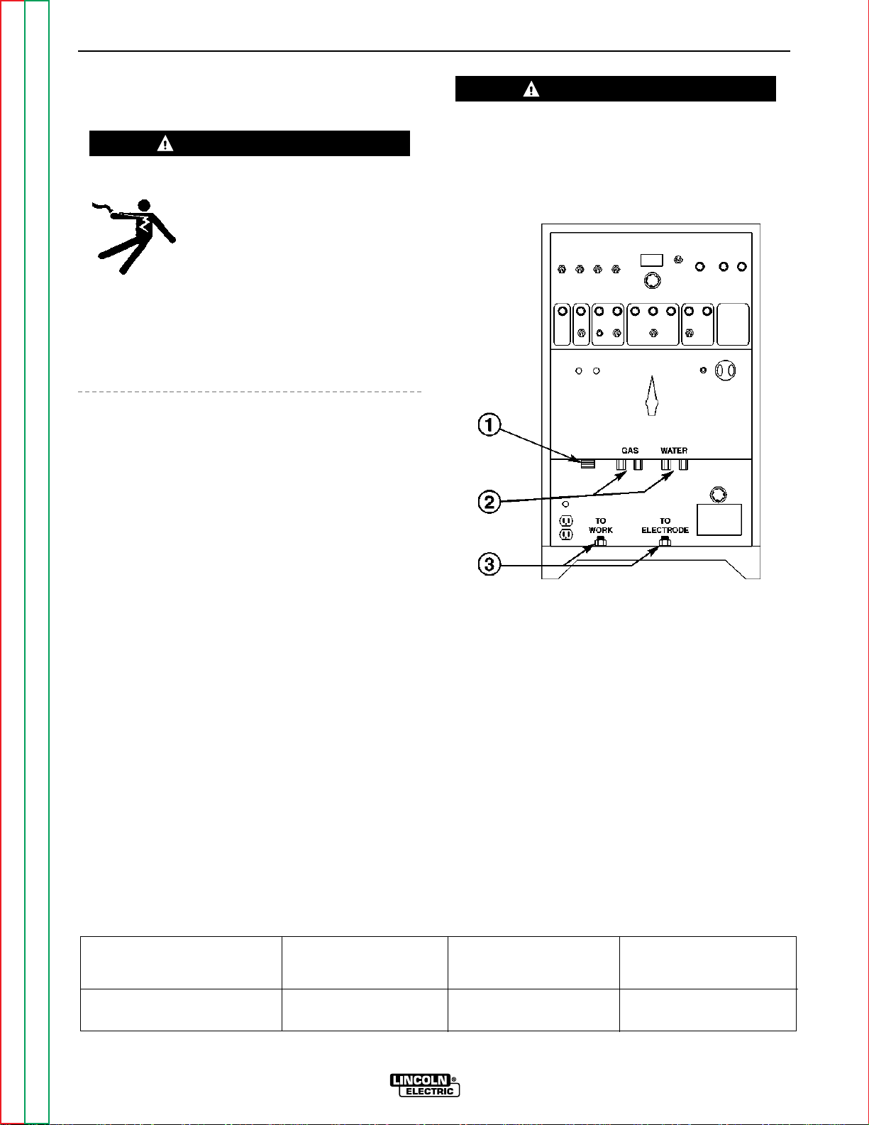
See Figure A.3 for the location of the work and electrode terminals, the gas and optional water solenoids,
and the Remote Receptacle.
TIG TORCH CONNECTION
WARNING
Observe the safety precautions necessary for handling
and using compressed gas containers. Contact your
supplier for specific information.
FIGURE A.3 – FRONT PANEL
TIG welding torches come with 15 ft (4.6m) and 25 ft
(7.6m) cables. Use the shorter length whenever possible to minimize possible radio interference problems.
With power source off, connect the torch cable to the
“Electrode” terminal on the welder. Connect a separate work cable to the “Work” terminal of the welder.
See Table A.3 for recommended work cable sizes.
Both work and electrode cables should be routed
through the cable strain relief holes provided in the
base directly below the welding ouput terminals.
Connect the TIG torch gas and water fittings to the
welder fittings. any torch with fittings that conform to
Compressed Gas Association (CGA) standards can be
used.
The welder fittings have the following threads: Gas
Inlet and Outlet: 5/8”-18 right-hand female; Water inlet
and Outlet: 5/8”-18 left-hand female. The cylinder of
inert shielding gas must be equipped with a pressure
regulator and flow meter. Install a hose between the
flow meter and gas inlet on the welder.
TABLE A.3
CABLE SIZES FOR COMBINED LENGTHS OF COPPER ELECTRODE AND WORK CABLE
1. REMOTE RECEPTACLE
2. WATER AND GAS
SOLENOIDS
3. WORK (LEFT) AND
ELECTRODE TERMINALS
Return to Master TOC Return to Master TOC Return to Master TOC Return to Master TOC
Return to Section TOC Return to Section TOC Return to Section TOC Return to Section TOC
Lengths up to 100 to 200 ft 200 to 250 ft
Machine Size 100 ft (30 m) (30 to 61 m) (61 to 76 m)
350 Amp
40% Duty Cycle #1 (45mm2) 1/0 (55mm2) 2/0 (70mm2)
SQUARE WAVE TIG 355
Page 14

A-8 A-8
INSTALLATION
DO NOT operate a water-cooled torch unless water is
flowing. Water doesn’t flow until the solenoid is actuated.
If using a water-cooled torch with a Magnum water
cooler, connect the cooler water outlet to the “Water
Valve In” fitting. Connect the TIG torch inlet to the
“Water Valve Out” fitting.
If using a water-cooled torch with a free-running water
supply, install a water line between the welder “Water
Inlet” and the supply. Include a strainer in the water
supply line to prevent dirt particles from obstructing
water flow in the valve and cooling chamber of the TIG
torch. Failure to do so could result in water valve malfunction and overheating of the water-cooled torch.
Connect the torch water line to the welder “Water Out”
fitting. Use a nonmetallic drain line from the electrode
connection to the drain or water recirculating pump.
For other water coolers or torches, consult the manufacturer’s instructions for the water cooler or TIG torch
being used.
STICK ELECTRODE CABLE
CONNECTION
Turn the Power switch Off. Run the electrode and
work cables through the strain relief holes below the
welding output terminals and connect the cables to
the proper terminals. This strain relief prevents damage to the welding output terminals if the cables are
pulled excessively. Select cable size according to
Table A.3
WARNING
Do not connect a TIG torch and stick electrode cable
at the same time. They will both be electrically HOT
whenever the output terminals are energized.
Return to Master TOC Return to Master TOC Return to Master TOC Return to Master TOC
Return to Section TOC Return to Section TOC Return to Section TOC Return to Section TOC
SQUARE WAVE TIG 355
Page 15

Section B-1 Section B-1
TABLE OF CONTENTS
- OPERATION SECTION -
Operation...............................................................................................................................Section B
Safety Instructions ...............................................................................................................B-2
General Description....................................................................................................................B-3
Recommended Processes...................................................................................................B-3
Operational Features and Controls......................................................................................B-3
Design Features and Advantages........................................................................................B-3
Welding Capability................................................................................................................B-4
Limitations............................................................................................................................B-4
Controls and Settings.................................................................................................................B-5
Upper Case Front Controls..................................................................................................B-5
Lower Case Front Controls................................................................................................B-11
Hand and Foot Amptrol™ Operation.................................................................................B-13
Welding Operation....................................................................................................................B-15
Initial Start-up .....................................................................................................................B-15
Stick Welding ....................................................................................................................B-15
TIG Welding Guidelines......................................................................................................B-15
TIG Welding Sequence of Operation (2-Step Mode).........................................................B-20
TIG Welding Sequence of Operation (4-Step Mode).........................................................B-20
Overload Protection ..................................................................................................................B-21
Auxiliary Power.........................................................................................................................B-21
Return to Master TOC Return to Master TOC Return to Master TOC Return to Master TOC
SQUARE WAVE TIG 355
Page 16

B-2 B-2
OPERATION
OPERATING INSTRUCTIONS
Read and understand this entire section of operating
instructions before operating the machine.
SAFETY INSTRUCTIONS
WARNING
ELECTRIC SHOCK can kill.
• Do not touch electrically live parts or
electrodes with your skin or wet clothing.
• Insulate yourself from the work and ground.
• Always wear dry insulating gloves.
FUMES AND GASES can be
dangerous.
• Keep your head out of fumes.
• Use ventilation or exhaust to remove
fumes from breathing zone.
WELDING SPARKS can cause
fire or explosion.
• Keep flammable material away.
• Do not weld on containers that have held combustibles.
ARC RAYS can burn.
• Wear eye, ear, and body protection.
Observe additional Safety Guidelines detailed in
the beginning of this manual.
Return to Master TOC Return to Master TOC Return to Master TOC Return to Master TOC
Return to Section TOC Return to Section TOC Return to Section TOC Return to Section TOC
SQUARE WAVE TIG 355
Page 17

B-3 B-3
OPERATION
GENERAL DESCRIPTION
The Square Wave TIG 355 is a constant curr ent, single
range square wave AC/DC TIG (GTAW) arc welding
power source with built-in high frequency stabilization.
It also has stick (SMAW) capability. The Square Wave
TIG 355 gives the operator full control of the welding
current plus the ability to preset weld and start currents. Preflow and postflow timers are included for
shielding gas and cooling water control. Altogether
the many features of the machine allow part or all of a
weld cycle to be preset or "programmed," which simplifies the TIG welding process.
The Square Wave TIG 355 includes advanced featur es
such as Auto-Balance™ 2-Step/4-Step Arc Start
Switch Operation, start controls, crater controls, spot
timer, and status LEDs. Preflow and postflow timers
allow control of shielding gas and cooling water.
RECOMMENDED PROCESSES
The Square Wave TIG 355 is recommended for TIG
(GTAW) and stick (SMAW) welding processes within its
output capability of 2 to 400 amps on both AC and DC
polarity. It is compatible with all Magnum TIG accessories as well as many industry standard TIG torches,
hoses, and water coolers. (See the Accessories section of this manual.)
DESIGN FEATURES AND ADVANTAGES
• Designed to NEMA EW-1 and Inter national IEC-974
Standards.
• Single output range of 2-400 amps covers the
majority of TIG welding applications.
• Solid State Output Contactor: no noise, no parts to
wear.
• Digital Ammeter and Voltmeter for precise readings
from 2-400 amps welding.
• Welding current limit can be preset from 2-400
amps and is displayed on the ammeter when not
welding.
• Auto Balance™ circuitry automatically provides the
proper amount of cleaning and penetration when
AC TIG welding. Manual AC wave balance adjustment is also possible.
• 2-Step/4-Step Arc Start switch capability.
• Spot control for 2-Step Arc Start switch mode.
• TIG Pulser with On/Off selection, and Pulses Per
Second adjustment. Background current and duty
cycle are automatically adjusted according to the
peak welding current.
• Crater Fill control for current fade-out at the end of
a weld.
OPERATIONAL FEATURES AND
CONTROLS
The following operational controls are standard on the
Square Wave TIG 355: Local/Remote current control
switch, Stick/TIG mode selection switch, TIG 2Step/TIG 4-Step mode selection switch, High
Frequency Continuous/Start/Off switch, Peak Current
control, Volts/Amps switch for the digital ammeter
reading, AC Wave Balance control, Afterflow timer for
shielding gas and water flow, Ar c For ce curr ent contr ol
for stick welding, Preflow timer for shielding gas and
water flow, Spot Time Controls, Start current/time
controls, Pulse controls (pulses per second, background % peak current, pulse % on), and Crater Fill
controls (fade-out, % peak current).
The following additional features are also standard:
Digital ammeter selectable for either volts or amps;
Status Indicator LEDs for gas and water, high frequency, arc established, start, peak, background, crater fill.
• Adjustable preflow time from 0 to 10 seconds.
Preflow time is eliminated if welding restarts during
gas afterflow of previous weld. This avoids unnecessary delays when making repeated welds.
• Adjustable afterflow time control.
• Locate/Remote current selection.
• Stick/TIG selection.
• Arc Force control of added current when electrode
shorts to the work in stick mode.
• Continuous/Start/Off High Frequency selection.
• DC+/AC/DC- Polarity switch.
• Power Factor Correction for lower input currents
and smaller input wire sizes.
• Remote Receptacle for Amptrol™ or Arc Start
switch.
• Low Voltage Arc Start switch circuit (24 VAC) for
maximum operator safety.
• Gas and optional water valves: Inlet and outlet fittings conform to Compressed Gas Association
(CGA) standards.
Return to Master TOC Return to Master TOC Return to Master TOC Return to Master TOC
Return to Section TOC Return to Section TOC Return to Section TOC Return to Section TOC
• Built-In High Frequency Generator.
SQUARE WAVE TIG 355
Page 18

B-4 B-4
OPERATION
• 115 Volt receptacle with 15 amp circuit breaker.
• 220 Volt European (Schuko) type receptacle with 2
amp circuit breaker for water coolers (50/60Hz
machines only).
• Excellent arc starting and stability up through 400
amps.
• High resistance to AC arc rectification.
• No tungsten spitting within current range of electrode.
• Compact size, requires only a 22.25 in x 26 in (565
mm 660 mm) footprint.
• Strain relief holes in base for welding cables, gas
and water hoses and control cables.
• Easy access for input connections. Connections
are simple strip and clamp of input wires (no lugs
required).
• Low fan noise at idle.
• Modular construction for easy servicing.
• Unused controls are automatically locked out to
simplify setup. Examples: the AC Wave Balance
control has no effect in DC; the High Frequency and
gas and water valves do not operate in Stick mode;
TIG Pulser is locked out in the Stick mode.
WELDING CAPABILITY
The Square Wave TIG 355 is NEMA Class II (40) Power
Source rated 350 amps at 34 volts, 40% duty cycle.
The duty cycle is based upon a 10 minute time period.
(For 40% duty cycle, it is 4 minutes on and 6 minutes
off.) The overload capacity is 375 amps at 35 volts,
30% duty cycle.
The “Lincoln Plus” rating of 300 amps at 40 volts provides additional voltage to overcome voltage drops in
long cables when stick welding at high currents.
LIMITATIONS
• The Square Wave TIG 355 is not recommended for
arc gouging. The machine's output capacity is too
limited.
• The Square Wave TIG 355 is not recommended for
AC TIG welding with high concentrations of helium
shielding gas. Starting problems and arc rectification may occur.
• The Square Wave TIG 355 is not recommended for
pipe thawing.
• Recessed panels protect controls, output terminals,
gas and water fittings.
• Large safety margins and protective circuits protect
rectifiers from transient voltages and high currents.
• Line voltage compensated.
• Thermostatically protected.
• Electronic over current protection.
Return to Master TOC Return to Master TOC Return to Master TOC Return to Master TOC
Return to Section TOC Return to Section TOC Return to Section TOC Return to Section TOC
SQUARE WAVE TIG 355
Page 19
B-5 B-5
OPERATION
CONTROLS AND SETTINGS
UPPER CASE FRONT CONTROLS
Controls on the upper case front control panel are
used for manual TIG and stick welding. Their functions are described below . Some controls ar e active in
both TIG and stick welding, while others are active in
TIG only. Refer to Figure B.1 for control locations.
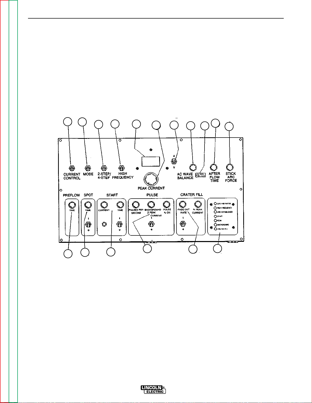
FIGURE B.1 – UPPER CASE FRONT CONTROLS
1
2
3
4
5
6 7
8
10
9
11
1. REMOTE/LOCAL CURRENT CONTROL SWITCH 7. VOLTS/AMPS METER SWITCH 12. PREFLOW TIMER
2. MODE SWITCH (STICK/TIG) 8. AC WAVE BALANCE 13. SPOT CONTROLS
3. 2-STEP/4-STEP SWITCH 9. AUTO-BALANCE™ LED 14. START CONTROLS
4. HIGH FREQUENCY SWITCH 10. AFTERFLOW 15. PULSE CONTROLS
5. DIGITAL VOLTMETER/AMMETER 11. STICK ARC FORCE 16. CRATER FILL CONTROLS
6. PEAK CURRENT CONTROL 17. STATUS INDICATOR LEDs
Return to Master TOC Return to Master TOC Return to Master TOC Return to Master TOC
Return to Section TOC Return to Section TOC Return to Section TOC Return to Section TOC
12
13
14
15
SQUARE WAVE TIG 355
16
17
Page 20

B-6 B-6
OPERATION
UPPER CASE FRONT CONTROL PANEL
The upper case front panel controls are used for manual TIG and stick welding.
1. CURRENT CONTROL SWITCH
A two-position toggle switch:
LOCAL (PANEL): Current is controlled by the
machine settings; remote Amptrol has no affect
on current.
REMOTE: Current is controlled by a remote
Amptrol up to the current set on the machine.
2. MODE SWITCH
A two-position toggle switch:
STICK: For stick electrode welding (SMAW), this
position makes the Stick Arc Force control active.
This switch locks out high frequency, the gas and
water valves, and the AC Wave Balance control.
The STICK position also locks out the Spot Time,
Start Time and Crater Fill controls. The Pulse controls are locked out except when an Arc Start
switch connected to the Remote receptacle is
closed.
TIG: For TIG welding (GTAW), this position locks
out the Stick Arc Force control. It makes all other
controls active. To start and stop the welding
sequence and to get output current, an Amptrol or
Arc Start switch must be used when this switch is
in the TIG position.
3. 2-STEP/4-STEP SWITCH
A two-position toggle switch: (Locked out in the
STICK mode.)
2-STEP: For use with an Arc Start switch or an
Amptrol remote current control. The Arc Start
switch must be held down during the entire weld
cycle. Pressing the Arc Start switch starts the
Preflow cycle, and releasing the switch ends the
weld cycle.
NOTE: If the Crater Fill switch (Item 16) is ON,
welding will continue after the Arc Start switch is
released. (See Crater Fill controls.)
4-STEP: For use with an Arc Start switch only . The
Arc Start switch must be pressed and released to
start the weld cycle. Pressing and releasing the
Arc Start switch a second time ends the weld
cycle. This eliminates the need to continuously
hold down the Arc Start switch during a weld. If
the Preflow timer (Item 12) is being used, the Arc
Start switch must be held down during the Preflow
time. The Arc switch can be released once an arc
is established.
Return to Master TOC Return to Master TOC Return to Master TOC Return to Master TOC
Return to Section TOC Return to Section TOC Return to Section TOC Return to Section TOC
NOTE: If the Crater Fill switch (Item 16) is ON,
welding will continue after the Arc Start switch is
pressed and released the second time. (See
Crater Fill Controls.)
NOTE: If the arc goes out while welding in the 4Step mode, the machine will try to re-establish an
arc for a period of two seconds. The output contactor will remain closed, and the High Frequency,
if in the Start Only or continuous mode, will be
activated. If an arc does not re-establish within
two seconds, the weld cycle is automatically
ended.
4. HIGH FREQUENCY SWITCH
A three-position toggle switch: (Locked out in
STICK mode).
CONTINUOUS: High frequency will come on after
the gas Preflow time and remain on until the weld
is stopped.
START : High Frequency will come on for 1-2 seconds after an arc is established, then go off.
(When AC TIG welding, the high frequency will
stay on until after the Start period and come on
again during the Crater Fill period.)
OFF: No high frequency.
5. DIGITAL VOLTMETER/AMMETER
Displays the output voltage of the welder when the
VOLTS/AMPS switch (Item 7) is held in the
“VOLTS” position.
When the VOLTS/AMPS SWITCH IS IN THE
“AMPS” position, this display functions as an
ammeter.
When you are not welding, the ammeter displays
the value preset by the Peak Current control.
When you are not welding and the Start Current
Display pushbutton is pressed, the ammeter will
display the preset Start (Item 14). (See Start
Controls)
NOTE: The ammeter display is an indicator of the
preset current. Actual welding current will be
slightly different.
While you are welding, the ammeter displays the
actual welding current. The ammeter is accurate
within ±3% of its reading or ±2 amps, whichever is
greatest. The ammeter displays RMS current.
(RMS current is the actual “heating value” of the
arc.) NOTE: Some types of ammeters will not
accurately read true RMS currents, particularly
when AC TIG welding aluminum. AC only ammeters may read as much as 40% low when measuring AC TIG welding currents.
SQUARE WAVE TIG 355
Page 21

B-7 B-7
OPERATION
6. PEAK CURRENT CONTROL
Presets the maximum welding current the
machine will produce, from 2 through 400 amps.
The preset current is displayed on the digital
ammeter when you are not welding.
NOTE: The ammeter display is an indicator of the
preset current. Actual welding current will be
slightly different.
If you use an Amptrol, it will control the current
from 2 amps up to the current preset by the Peak
Current control. See the section, “Hand and Foot
Amptrol Operation” for proper use of hand and
foot Amptrols.
If pulsing, the peak current is the current set and
controlled by the Peak Current control (Item 6) and
the Amptrol.
7. VOLTS/AMPS SWITCH
A two-position, spring-loaded toggle switch for
selecting either arc voltage or welding current/preset current to be displayed on the digital meter.
To read the arc voltage, you must hold the switch
in the “Volts” position. This spring-loaded switch
always returns to the “AMPS” position when
released.
8. AC WAVE BALANCE
This control is active only in AC TIG mode. It controls the amounts of positive and negative current
in the AC output. It has no effect on stick or DC
TIG welding.
AUTO BALANCE™: This setting provides automatic adjustment of the AC wave balance, and it is the
preferred balance setting for most welding conditions. This setting gives the ideal amount of cleaning and penetration, based on the welding current
output. When the control is set to the Auto
Balance position, the Auto Balance LED (Item 9)
will light. This feature operates only in the AC TIG
mode.
For those procedures when manual adjustment of
the Wave Balance control is necessary, use the
following as a guide:
.
CAUTION
Use only the amount of “cleaning” required. Greater
amounts of positive current will heat the tungsten
more and possibly cause it to melt or “spit.” Also, the
arc is usually more flared and less stable with more
positive “cleaning” current.
PENETRATION (Above “3” on the dial): Provides
more negative current than positive current. The
“cleaning” effect will be reduced, but the arc plasma will be more concentrated and more easily
directed to where the heat is needed. The
reduced amount of positive current allows the
tungsten to run cooler at a given current than
when set balanced.
In general, use just enough “cleaning” to remove
oxides and to give good wetting of the puddle.
9. AUTO BALANCE™LED
Illuminates only when the Auto Balance function is
active. The welder must be in the AC TIG mode,
with the AC Wave Balance control fully clockwise.
10. AFTERFLOW
This control adjusts the amount of time the gas
and water valves stay open after the end of a weld.
Minimum time is approximately 5 seconds; maximum is approximately 55 seconds. Use enough
Afterflow time to protect the hot tungsten with gas
shielding until it cools. Too short of a time will
cause the tungsten to oxidize and become contaminated. When in doubt, set a longer time, then
reduce it to a time that still gives good protection.
PREFLOW
All machines have an adjustable Preflow time.
If a new weld is started during the Afterflow time of
a previous weld, the Preflow time is bypassed,
since gas shielding is already present. This allows
new welds to start immediately, with no preflow
delay.
11. ARC FORCE
BALANCED: The amounts of positive and negative
are the same.
CLEANING (Below “3” on the dial): Provides more
positive current than negative current. Since the
positive current produces the “cleaning” or oxide
removal on aluminum, this setting is used for
heavily oxidized aluminum.
Return to Master TOC Return to Master TOC Return to Master TOC Return to Master TOC
Return to Section TOC Return to Section TOC Return to Section TOC Return to Section TOC
This control is active only in Stick mode. It controls the amount of current added to the welding
current when the electrode shorts to the work.
At Minimum, no extra short circuit current is
added. The arc will be softer and will have less
spatter but may be more prone to sticking.
SQUARE WAVE TIG 355
Page 22

B-8 B-8
OPERATION
At Maximum, the arc will be more forceful and less
prone to sticking but will produce more spatter.
12. PREFLOW
This control adjusts the amount of time the gas
and water valves are open before the arc starts. It
is adjustable from 0 to 10 seconds.
The Preflow time occurs only if the valves were
closed (no gas flow) when the Arc Start switch or
Amptrol was pressed. If a new weld is started
while the gas valve is still on during the Afterflow
time of a previous weld, the Preflow time is
bypassed since gas shielding is already present.
This allows new welds to start immediately with no
preflow delay.
Note that since the arc cannot start during the
Preflow time, a long Preflow setting can cause
complaints about arc starting. In general, a
Preflow time of 0.5 seconds is satisfactory for
most applications.
13. SPOT CONTROLS
Spot Switch — A two-position toggle switch:
Recommended for use in the 2-step Arc Start
Switch mode only.
ON: Spot Time control is active. Once the arc is
established, the Spot time begins. At the end of
the Spot time (or if the Arc Start switch/Amptrol is
released sooner), the arc stops. (If Crater Fill [Item
16] is on, downslope begins.)
OFF: Locks out the Spot Time control.
Spot Time Control: Not active if the Spot switch
is off. Adjusts weld time from 0.1 to 5 seconds.
Weld time is the time from when the arc is fully
established until the arc is turned off (or when
Crater Fill downslope is started). The Arc Start
switch or Amptrol must be held down during the
Spot time; if it is released before the end of the
Spot time, the arc will be turned off (or Crater Fill
started).
14. START CONTROLS
Start Switch — A two-position toggle switch:
ON: Start Current control is active. At the begin-
ning of the weld, current will be the value preset by
the Start Current control. Th position of the
Amptrol has no effect on this current.
OFF: Locks out Start Current and Time controls.
Press and hold in this pushbutton to display the
Start Current preset by the Start Current control.
(The Volts/Amps switch (Item 7) must be in the
“AMPS” position to read preset current.)
Start Current Control
Locked out if the Start switch is off.
Presets the current that will be provided at the
start of the weld. The current can be preset from
2 to 400 amps. The position of the amptrol has no
effect on the initial current. The present Start
Current is displayed on the Ammeter when the
pushbutton is pressed before welding.
A “hot” start is used to quickly heat the tungsten
and work, usually on DC TIG welding. Set the
Start Current higher than what the welding current
will be. After the time is set on the Start Time control, the current will step down to the current set
and controlled by the Peak Current control (Item 6)
and the Amptrol.
A “soft” start is used to preheat the tungsten and
work, usually on AC TIG welding. Set the Start
Current lower than what the welding current will
be. The arc will establish at the Start Current and
then ramp up to the current set and controlled by
the Peak Current control (Item 6) and the Amptrol.
The time to get up to welding current is set by the
Start Time control. During the ramp up, the
Amptrol will affect the current that the ramp is
going toward and therefore the rate at which the
current increases.
Start Time Control
Locked out if the Start switch is off. Adjusts the
Start Time from approximately 0.1 to 10 seconds.
15. PULSE CONTROLS
Pulse Switch — A two-position toggle switch:
ON: Pulsing will begin as soon as an arc is established and will continue until the weld is completed. If you are using Start Controls, pulsing begins
after the Start Current. If you are using Crater Fill,
pulsing will continue during the downslope period.
OFF: Locks out Pulse controls.
Pulses per Second Control — Controls the num-
ber of pulses per second from approximately 0.1
to 10 pps. 0.1 pulses per second is slow pulsing
(one pulse every 10 seconds); 10 pulses per second is fast pulsing.
Start Current Display Pushbutton
Return to Master TOC Return to Master TOC Return to Master TOC Return to Master TOC
Return to Section TOC Return to Section TOC Return to Section TOC Return to Section TOC
Background % Peak Current Control —
Controls the background (low pulse) current from
zero to 100% of the peak current set and controlled by the Peak Current control (Item 6) and the
Amptrol.
SQUARE WAVE TIG 355
Page 23

B-9 B-9
OPERATION
Example: The Peak Current control is preset at 50
amps and the Amptrol is partially down, giving a
peak current of 30 amps. If the Background
Current control is set at 50%, the Background (low
pulse) current will be 15 amps.
The Amptrol raises and lowers the Peak current.
Since Background current is always a percentage
of Peak current, the Amptrol also raises and lowers the Background current.
Pulse % On — Controls the percentage of the
pulse cycle that is at the Peak current.
Example: You are pulsing at 1 Pulse per second
with a 30% Pulse % On setting. The welding current would be at the Peak current for 0.3 seconds
and at the Background current for the remainder
of the cycle, 0.7 seconds.
16. CRATER FILL CONTROLS
Use the Crater Fill controls to automatically control
current fade-out at the end of a weld. LOCAL current control (Item 1) MUST be used when Crater
Fill is used.
Crater Fill Switch — A two-position toggle
switch.
ON: Crater Fill Fade-out will begin when the Arc
Start Switch or Amptrol is released (2-Step mode)
or pressed and released a second time (4-Step
mode). If used with Spot Time (item 13), Crater Fill
begins at the end of the Spot Time. The current
control (item 1) switch must be in LOCAL when
using Crater Fill.
OFF: Locks out Crater Fill controls.
Fade-out Control — Controls how slowly the cur-
rent fades out. The FAST setting will cause current
to ramp down from the welding current toward 2
amps in approximately 1/2 second; the SLOW setting, in approximately 20 seconds. The time for
downslope to the Crater Fill Current level depends
on the difference between the weld current and
the Crater Fill Current.
Crater Fill % Peak Current Control — Controls
the final Crater Fill current from zero to 100% of
the weld current preset on the Peak Current control.
Example: WIth a Crater Fill % Current setting of
20% and a weld current preset at 100 amps, the
current will fade from 100 amps to 20 amps and
then dwell at 20 amps for about 1-1/2 seconds
before the arc goes out.
The final Crater Fill current dwell time is approximately 1-1/2 seconds, regardless of Crater Fill
control settings.
17. STATUS INDICATOR LEDs — Seven Light
Emitting Diodes (LEDs) which light when their
function is active.
• GAS & WATER LED is on when the solenoid
valves are open, from the beginning of Preflow
to the end of Afterflow.
• HIGH FREQUENCY LED is on when the high
frequency circuit is on.
Return to Master TOC Return to Master TOC Return to Master TOC Return to Master TOC
Return to Section TOC Return to Section TOC Return to Section TOC Return to Section TOC
FIGURE B.2 – STATUS INDICATOR LIGHT SEQUENCE
SQUARE WAVE TIG 355
SQUARE WAVE TIG 355
Page 24

B-10 B-10
OPERATION
• ARC ESTABLISHED LED goes on when the arc
is fully established and goes out if the arc goes
out.
• START LED is on from the time the arc is established until current begins to go up (soft start) or
down (hot start). Note that the Start LED is off
during upslope if a soft start is used.
• PEAK LED goes on after the Start period. If the
Pulse switch is on, the Peak LED goes off during the Background periods. The Peak LED and
Background LED will alternate when pulsing.
• BACKGROUND LED is on during the
Background (low pulse) period of pulsing.
• CRATER FILL LED is on during the Fade-Out
downslope and final current periods.
NOTE: An LED will light in response to the control circuit command, even if other components do not work.
For example, if the gas supply is turned off or the gas
solenoid valve malfunctions or the fuse is blown, the
gas will not flow even though the Gas and Water LED
lights up. Another example is the High Frequency LED
which can light, yet there will not be high frequency
due to a blown fuse or defective high frequency circuit
or spark gaps set too large.
The Status Indicator LEDs are useful for understanding
which functions are active during a weld sequence
and for how long. They are useful for setting times of
the controls on the Function Panel. See Figure B.2.
The Status Indicator LED circuit board includes a
receptacle for plugging in the circuit board included
with the Optional Interface Kit.
Return to Master TOC Return to Master TOC Return to Master TOC Return to Master TOC
Return to Section TOC Return to Section TOC Return to Section TOC Return to Section TOC
SQUARE WAVE TIG 355
Page 25

B-11 B-11
OPERATION
LOWER CASE FRONT CONTROLS
Refer to Figure B.3 for the location of the following controls.
FIGURE B.3 – LOWER CASE FRONTCONTROLS
4
5
3
2
1
9
6
8
7
Return to Master TOC Return to Master TOC Return to Master TOC Return to Master TOC
Return to Section TOC Return to Section TOC Return to Section TOC Return to Section TOC
SQUARE WAVE TIG 355
Page 26

B-12 B-12
OPERATION
1. POWER ON/OFF — A momentary start/stop
pushbutton, which controls the input contactor. If
the input power supply goes off or if the thermostat in the welder trips, the start pushbutton must
be pressed to restart the welder.
2. PILOT LIGHT — Indicates when the input contac-
tor is energized (power is on).
CAUTION
Do not switch polarity under load.
3. POLARITY SWITCH — Selects DC-/AC/DC+
4. FUSE F1 — 0.5 amp control circuit fuse protects
the control transformer from overloads. Input
overvoltage protection circuitry will blow this fuse
to protect electronic components if the input voltage to the welder is too high (more than 40% over
rated voltage). If this fuse blows, the digital meters
will not light and the input contactor will not latch
when the Power On/Off Start pushbutton is
pressed and released.
5. FUSE F2 — 1.5 amp gas, water, and high fre-
quency fuse protects the circuitry that drives the
gas and water valves and the high frequency supply transformer. If this fuse blows, the valves and
high frequency will not work. However, the LEDs
for Gas and Water and High Frequency will still
light.
6. REMOTE RECEPTACLE — A six-pin circular con-
nector for an Arc Start switch or an Amptrol
remote current control.
7. 115 VOLT RECEPTACLE AND CIRCUIT BREAK-
ER — A duplex 15 amp grounded NEMA 5-15R
receptacle and 15 amp circuit breaker. Fifteen
amps of 115 volt AC power is available continuously whenever the power is on. The circuit
breaker button will pop out if it trips. Reset by
pushing it in after the circuit breaker cools and the
overload has been removed.
8. HIGH FREQUENCY INTENSITY CONTROL AND
SPARK GAP — This control changes the high frequency intensity. Use the lowest intensity which
still gives good arc starting to minimize Radio
Frequency Interference (RFI). The spark gap is set
at the factory to the normal setting marked on the
cover plate. Instructions for larger or smaller gap
settings are also on the cover plate.
9. GAS AND OPTIONAL WATER VALVES —
Solenoid valves that open at the beginning of the
Preflow time and close at the end of the Afterflow
time.
The gas valve inlet and outlet are standard 5/18-18
right-hand female fittings. The water valve inlet
and outlet are standard 5/8-18 left-hand female fittings. The fittings conform to CGA (Compressed
Gas Association) standards. Use a water line
strainer to prevent particles from jamming the
water valve.
Return to Master TOC Return to Master TOC Return to Master TOC Return to Master TOC
Return to Section TOC Return to Section TOC Return to Section TOC Return to Section TOC
SQUARE WAVE TIG 355
Page 27

B-13 B-13
OPERATION
HAND AND FOOT AMPTROL OPERATION
Both the Hand and Foot Amptrol (optional kits K870 or
K812) work in a similar manner. They are meant to be
used for remote current control when Remote Current
control is selected. The TIG 2-Step mode must be
selected when using an Amptrol for remote current
control. As explained below, Amptrols can also be
used as arc start switches if Local Current control is
selected.
For simplicity, the following explanation will refer only
to “Amptrols,” meaning both Foot and Hand models.
The term “minimum” refers to a Foot pedal in the “up”
position, as it would be with no foot pressure, or a
Hand Amptrol in the relaxed position, with no thumb
pressure. “Maximum” refers to a fully depressed Foot
Amptrol, or a fully extended Hand Amptrol.
The Amptrol is capable of controlling the output current from 2 amps to whatever current is preset on the
ammeter. For example, if the ammeter is preset for
200 amps and the Current Control switch is in the
Remote position, the Amptrol, when depressed just
past its minimum position, will cause the Square Wave
TIG 355 to weld at 2 amps. At the Amptrol’s maximum
position, the output would be near 200 amps. See
Figure B.4.
CAUTION
Since the full output of the current setting is available
when the Amptrol is fully depressed, care must be
taken not to set a current which will exceed the current
carrying capacity of the tungsten. When in doubt, use
a lower current setting first, then increase.
A similar situation occurs when the Start controls are
used. For example, a 3/32” (2.4 mm) tungsten is again
used for welding DC- up to 200 amps (preset on the
ammeter). A Start current of 50 amps is set on the
Start Level control. When you depress the Amptrol,
the start circuitry sets the output current to 50 amps.
If the Amptrol is kept near the minimum position, at the
end of the start period the output current will drop to 2
amps, causing the arc to go out in most cases.
Depress the Amptrol at least 1/4 of the way down, or
to around 70 amps, so that the tungsten remains lit
when the start period ends.
The same holds true for a “hot” start, or one in which
the Start current is set to a current higher than the current preset on the ammeter. Again, at the end of the
start period, the Amptrol must be depressed far
enough so that the machine output will be high
enough to keep the arc lit.
The best technique when using the start controls and
an Amptrol is to press the Amptrol to maximum at the
beginning of the weld, wait until the end of the start
period, and then back off on the amptrol only if the
current is too high.
If the Current Control switch is set to the Local position, an Amptrol can be used as an arc start switch.
Depressing the amptrol just past minimum will cause
the Amptrol’s built-in arc start switch to close, and
backing off completely causes the built-in start switch
to open. The Amptrol will have no effect on the welding current when used as an arc start switch. See
Figure B.5.
It is important to note that, for many applications, the
tungsten will not start an arc at only 2 amps. To start
an arc reliably, it is important to depress the Amptrol
far enough so that the machine output current is near
the tungsten operating range. (See Table B.2 for recommended tungsten currents.) In the example above,
a 3/32” (2.4 mm) tungsten may be used on DC- to
weld near 200 amps. To start the weld, the operator
may have to depress the Amptrol approximately 1/4 of
the way down, or to nearly 70 amps, in order to start
the arc. Merely depressing the Amptrol to its 2 amp
minimum position will not start the arc.
Return to Master TOC Return to Master TOC Return to Master TOC Return to Master TOC
Return to Section TOC Return to Section TOC Return to Section TOC Return to Section TOC
SQUARE WAVE TIG 355
Page 28
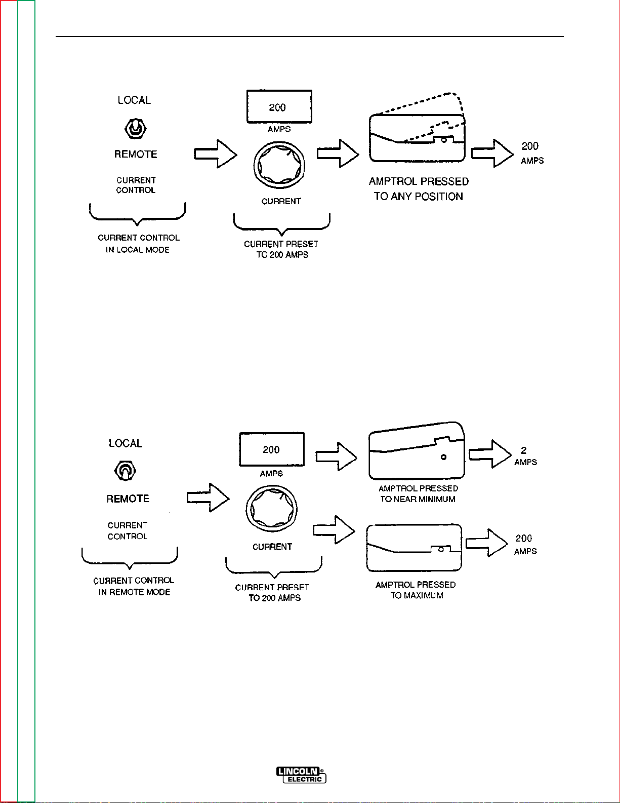
B-14 B-14
OPERATION
FIGURE B.4 – AMPTROLS USED WITH CURRENT CONTROL IN THE LOCAL POSITION
FIGURE B.5 – AMPTROLS USED WITH CURRENT CONTROL IN REMOTE POSITION
Return to Master TOC Return to Master TOC Return to Master TOC Return to Master TOC
Return to Section TOC Return to Section TOC Return to Section TOC Return to Section TOC
SQUARE WAVE TIG 355
Page 29

B-15 B-15
OPERATION
WELDING OPERATION
INITIAL START-UP
Be sure the Square Wave TIG 355 has been installed
correctly with respect to location, high frequency protection, input power, and output connections.
If you are TIG welding, connect a K870 or K812
Amptrol or a K814 Arc Start switch to the Remote
Receptacle. Check that the gas supply is on. Check
for the correct type and size of tungsten electrode, gas
cone size and torch size. If you are using a water
cooled torch, check that the water supply is on.
Press the Start (green) Power pushbutton. The input
contactor will pull in, the pilot light will come on, the
meter displays will light up, and the fans will start. In
TIG mode, the gas and water valves will open for one
Afterflow period to purge the lines. The ammeter will
display the preset current (if there is no load on the
welder output terminals). The voltmeter will read zero
in TIG mode, or from 60 to 70 in STICK mode.
Select the Electrode Polarity needed (DC-/AC/DC+) .
Set the controls by going from left to right across the
top row and then the bottom row , choosing the corr ect
setting for each. Note that the bottom row of controls
includes on/off switches to easily lock out the controls
within blocks (Spot, Start, Pulse, or Crater Fill) without
changing the settings. Also, note that some of the
controls are automatically locked out internally if they
do not apply in STICK mode or do not apply in TIG
mode. This reduces the number of controls which
must be set. See Table B.1 for examples of the effects
of the Function controls on TIG welding.
STICK WELDING
1. Remove the Amptrol or Arc Start switch from the
Remote Receptacle.
2. Turn the welder on. The pilot light on the front
panel indicates when the power is on.
3. Select LOCAL current control;
Select STICK mode. (High Frequency switch has
no effect in STICK mode.)
4. Preset the current with the Current control and the
Ammeter.
5. Set the desired Arc Force. (See CONTROLS AND
SETTINGS, item 11, “Arc Force.”) (The Wave
Balance and Afterflow controls have no effect in
STICK mode.)
6. Turn the Start switch OFF, or set the START controls for a hot start if needed. (See CONTROLS
AND SETTINGS, item 14, “Start Controls.”)
7. Strike an arc and weld. (There will be a buzzing
sound from the arc if you are AC welding, due to
the faster rate of current reversal of the Square
Wave.
TIG WELDING GUIDELINES
Recommended tungsten electrode sizes, stickouts,
currents, cup or nozzle sizes and gas flow are shown
in Table B.2. SINCE TIG APPLICATIONS CAN VARY,
THIS TABLE IS INTENDED AS A GUIDE ONLY.
Aluminum Welding: Set the Electrode Polarity switch
to AC, the High Frequency switch to CONTINUOUS,
and the Mode switch to TIG. Make all other control
settings to suit the size tungsten and current. In general, pure or zirconiated tungsten electrode is best for
aluminum and should have a “balled” end not exceeding the diameter of the tungsten. A buzzing sound will
occur in the arc when AC TIG welding aluminum. We
recommend that you set the AC Wave Balance control
to the Auto Balance position. For more information
see CONTROLS AND SETTINGS, item 8, “AC Wave
Balance.”
Stainless or Mild Steel Welding: Set the Electrode
Polarity switch to DC-, the High Frequency switch to
START, and the Mode switch to TIG. In general, 1% or
2% thoriated tungsten electrode is best for stainless or
mild steel and should have the end ground to a point.
If there is difficulty starting the arc, the tunsten may be
contaminated, or it may be too large to get up to operating temperature.
Return to Master TOC Return to Master TOC Return to Master TOC Return to Master TOC
Return to Section TOC Return to Section TOC Return to Section TOC Return to Section TOC
Note: Starting difficulties may often be due to not
pressing the Amptrol far enough. When the
Amptrol is just “cracked,” the minimum current
(2 amps) is produced. Pressing the Amptrol
more at the start of the weld will often solve
starting problems.
SQUARE WAVE TIG 355
Page 30
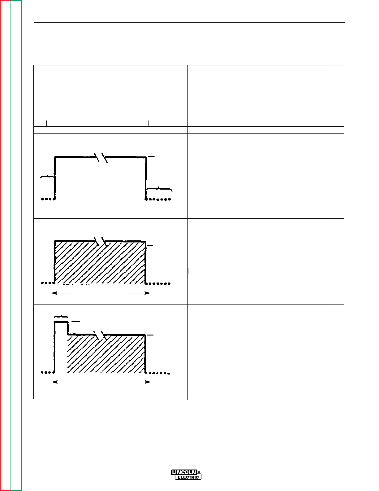
B-16 B-16
OPERATION
TABLE B.1
SPECIFIC EFFECTS OF CONTROLS
(illustrated in the 2-Step Mode for clarity)
EFFECT OF CONTROLS ON TIG WELDING
CLOSE ARC
START SWITCH
WELD BEGINS
PREFLOW
OPEN ARC
START SWITCH
PRESET
CURRENT
AFTERFLOW
LOCAL CURRENT CONTROL
ALL LOWER PANEL
SWITCHES OFF
REMOTE AMPTROL CONTROLS
START TIME
REMOTE AMPTROL CONTROLS
FROM 2 AMPS UP TO
PRESET CURRENT
START CURRENT
FROM 2 AMPS UP TO
PRESET CURRENT
PRESET
CURRENT
PRESET
CURRENT
REMOTE CURRENT CONTROL
ALL LOWER PANEL
SWITCHES OFF
LOCAL OR REMOTE CURRENT CONTROL
START SWITCH ON
START CURRENT SET HIGHER THAN
PRESET CURRENT (HOT START)
START TIME: VARIABLE
ALL OTHER PANEL SWITCHES OFF
HOT START
Return to Master TOC Return to Master TOC Return to Master TOC Return to Master TOC
Return to Section TOC Return to Section TOC Return to Section TOC Return to Section TOC
SQUARE WAVE TIG 355
Page 31

B-17 B-17
OPERATION
EFFECT OF CONTROLS ON TIG WELDING
CLOSE ARC
START SWITCH
MIN
TIME
START
START
CURRENT
WELD BEGINS
MAX START
TIME
REMOTE AMPTROL CONTROLS
FROM 2 AMPS UP TO
PRESET CURRENT
OPEN ARC
START SWITCH
PRESET
CURRENT
LOCAL OR REMOTE CURRENT CONTROL
START SWITCH ON
START CURRENT SET LOWER THAN
PRESET CURRENT (SOFT START)
START TIME: VARIABLE
ALL OTHER PANEL SWITCHES OFF
PRESET
CURRENT
FAST FADE-OUT
START
CURRENT
-3 SEC.
CRATER FILL TIME
PRESET
CURRENT
CRATER FILL
% CURRENT
OPEN
ARC
START
SWITCH
PRESET
CURRENT
(PEAK)
BACKGROUND
% CURRENT
SLOW
FADE-OUT
LOCAL CURRENT CONTROL
CRATER FILL SWITCH ON
CRATER FILL % CURRENT VARIABLE
FADE-OUT VARIABLE
ALL OTHER LOWER PANEL SWITCHES
CRATER FILL
% CURRENT
OFF
LOCAL CURRENT CONTROL
START SWITCH ON
(SOFT START SHOWN; MAY HAVE HOT
START)
CRATER FILL SWITCH ON
ALL OTHER PANEL SWITCHES OFF
LOCAL OR REMOTE CURRENT CONTROL
PULSE SWITCH ON
PULSES PER SECOND
BACKGROUND % DUTY CYCLE
PULSE % ON
ALL OTHER LOWER PANEL SWITCHES
OFF
START & CRATER FILL
PULSE SOFT STARTCRATER FILL
Return to Master TOC Return to Master TOC Return to Master TOC Return to Master TOC
Return to Section TOC Return to Section TOC Return to Section TOC Return to Section TOC
REMOTE AMPTROL CONTROLS
FROM 2 AMPS UP TO
PRESET CURRENT
SQUARE WAVE TIG 355
Page 32

B-18 B-18
OPERATION
EFFECT OF CONTROLS ON TIG WELDING
CLOSE ARC
START SWITCH
WELD BEGINS
START TIME
START CURRENT
BACKGROUND
% CURRENT
OPEN ARC
START SWITCH
PRESET
CURRENT
LOCAL CURRENT CONTROL
START SWITCH ON
(SHORT HOT START SHOWN)
PULSE SWITCH ON
CRATER FILL SWITCH ON
CRATER FILL
% CURRENT
(SLOW FADE-OUT SHOWN)
SPOT SWITCH OFF
START & PULSE & CRATER FILLSPOT
LOCAL OR REMOTE
SPOT SWITCH ON
ALL OTHER LOWER PANEL SWITCHES
OFF
SPOT TIME
CLOSE ARC
START SWITCH
SPOT TIME
CLOSE ARC
START SWITCH
PRESET
CURRENT
(SPOT TIME IS CUT SHORT IF ARC
START SWITCH IS OPENED BEFORE
END OF SPOT TIME)
OPEN ARC
START SWITCH
PREFLOW
REMOTE AMPTROL CONTROLS CURRENT
FROM 2 AMPS UP TO PRESET CURRENT
AFTER SPOT TIME
THE SPOT TIMER CAN BE USED TO TIME A PROGRAMMED SEQUENCE OF START AND/OR
PULSE UP TO 5 SECONDS LONG, OPTIONALLY FOLLOWED BY CRATER FILL. IF CRATER FILL
IS USED, FADE-OUT BEGINS AT THE END OF THE SPOT TIME.
Return to Master TOC Return to Master TOC Return to Master TOC Return to Master TOC
Return to Section TOC Return to Section TOC Return to Section TOC Return to Section TOC
SPOT & START PULSE & CRATER FILL
SQUARE WAVE TIG 355
Page 33

B-19 B-19
OPERATION
TABLE B.2
TYPICAL CURRENT RANGES
(1)
FOR TUNGSTEN ELECTRODES
(2)
DCEN (-) DCEP(+)
AC
Unbalanced Wave Balanced Wave
Approximate Argon
Gas Flow Rate
C.F.H. (l/min)
Tungsten 1%, 2% 1%, 2%
Electrode 1%, 2% 1%, 2% Thoriated Thoriated TIG Torch
Diameter Thoriated Thoriated Pure Tungsten Pure Tungsten Stainless Nozzle
in. (mm) Tungsten Tungsten Tungsten Zirconated Tungsten Zirconiated Aluminum Steel Size
.010 (.25) 2-15
0.020 (.50) 5-20
0.040 (1.0) 15-80
(3)
(3)
3)
(
2-15 2-15 2-15 — 3-8 (2-4) 3-8 (2-4) 4,5,6
5-15 5-20 10-20 5-20 5-10 (3-5) 5-10 (3-5)
10-60 15-80 20-30 20-60 5-10 (3-5) 5-10 (3-5)
(4), (5)
1/16 (1.6) 70-150 10-20 50-100 70-150 30-80 60-120 5-10 (3-5) 9-13 (4-6) 5,6
3/32 (2.4) 150-250 15-30 100-160 140-235 60-130 100-180 13-17 (6-8) 11-15 (5-7) 6,7,8
1/8 (3.2) 250-400 25-40 150-210 225-325 100-180 160-250 15-23 (7-11) 11-15 (5-7)
5/32 (4.0) 400-500 40-55 200-275 300-400 100-240 200-320 21-25 (10-12) 13-17 (6-8) 8,10
3/16 (4.8) 500-750 55-80 250-350 400-500 190-300 290-390 23-27 (11-13) 18-22 (8-10)
1/4 (6.4) 750-1000 80-125 325-450 500-630 250-400 340-525 28-32 (13-15) 23-27 (11-13)
(1) When used with argon gas. The current ranges shown must be reduced when using argon/helium or pure helium shielding gases.
(2) Tungsten electrodes are classified as follows by the American Welding Society (AWS):
Pure.................................EWP
1% Thoriated..................EWTh-1
2% Thoriated..................EWTh-2
Though not yet recognized by the AWS, Ceriated Tungsten is now widely accepted as a substitute for 2% Thoriated Tungsten in AC and DC applications.
(3) DCEP is not commonly used in these sizes.
(4) TIG torch nozzle “sizes” are in multiples of 1/16ths of an inch:
# 4 = 1/4 in. (6mm)
# 5 = 5/16 in. (8mm)
# 6 = 3/8 in. (10mm)
# 7 = 7/16 in. (11mm)
#8 = 1/2 in. (12.5mm)
#10 = 5/8 in. (16mm)
(5) TIG torch nozzles are typically made from alumina ceramic. Special applications may require lava nozzles, which are less prone to breakage, but cannot withstand high
temperatures and high duty cycles. Currents above 350 amps require metal nozzles on water cooled torches.
Return to Master TOC Return to Master TOC Return to Master TOC Return to Master TOC
Return to Section TOC Return to Section TOC Return to Section TOC Return to Section TOC
SQUARE WAVE TIG 355
Page 34

B-20 B-20
OPERA TION
TIG WELDING SEQUENCE OF
OPERATION (2-STEP MODE)
WARNING
Do not leave stick electrode welding cable connected.
It will be electrically “hot” when TIG welding.
1. Connect an Amptrol or Arc Start switch to the
Remote Receptacle.
2. Turn the welder, water supply (if equipped) and
gas supply on. The pilot light on the front panel
indicates when the power is on.
3. Select REMOTE or LOCAL current control
(REMOTE requires an Amptrol).
Select TIG mode.
Select CONTINUOUS or START high frequency.
Select AC or DC- electrode polarity. See Table B.3
for recommended polarity settings.
TABLE B.3
RECOMMENDED SETTINGS FOR TIG WELDING
Electrode High Frequency
Type of Welding Polarity Switch
Stainless Steel DC- Start
Aluminum and
Magnesium AC Continuous
Other Metals DC- Start
hose and torch. After a time determined by the
Preflow control setting, the high frequency
becomes available to strike the arc.
11. Hold the Arc Start Switch down or operate the
Amptrol until the weld is completed. Release the
Arc Start switch or the Amptrol to stop the arc.
When the Afterflow timer completes the cycle, the
gas and water valves close. To make another
weld, repeat steps 10 and 11.
TIG WELDING SEQUENCE OF
OPERATION (4-STEP MODE)
WARNING
Do not leave stick electrode welding cable connected.
It will be electrically “hot” when TIG welding.
1. Connect an Arc Start switch to the Remote
Receptacle.
2. Turn the welder, water supply (if so equipped) and
gas supply on. The pilot light on the front panel
indicates when the power is on.
3. Select LOCAL current control. Select TIG mode.
Select CONTINUOUS or START high frequency.
Select AC or DC- electrode polarity (See Table
B.3 for recommended polarity settings).
4. Preset the maximum current with the Peak
Current control and the Ammeter.
5. (Arc Force Control has no effect in TIG mode.)
4. Preset the maximum current with the Curr ent control and the Ammeter.
5. (Arc Force control has no effect in TIG mode.)
6. If in AC, set AC Wave Balance control. (See CONTROLS AND SETTINGS, item 8, “AC Wave
Balance.” This control has no effect in DC.)
7. Set Afterflow time.
8. Set Function Panel controls as needed. (See
CONTROLS AND SETTINGS.)
9. Press the Arc Start switch or Amptrol and set the
gas flowmeter. The welder is now ready for welding.
10. Position the tungsten electrode at the start of the
weld at a 65° to 75° angle with the horizontal so
that the electrode is approximately 1/8” (3.2 mm)
above the workpiece. Press the Arc Start switch
or operate the Amptrol. This opens the gas and
water valves to automatically purge air from the
Return to Master TOC Return to Master TOC Return to Master TOC Return to Master TOC
Return to Section TOC Return to Section TOC Return to Section TOC Return to Section TOC
6. If in AC, set AC Wave Balance control. (See CONTROLS AND SETTINGS, item 8, “AC Wave
Balance. This control has no effect in DC.)
7. Set Afterflow time.
8. Set Function Panel controls as needed. (See
CONTROLS AND SETTINGS, “Lower Case Front
Controls”)
9. Press the Arc Start switch and set the gas
flowmeter. The welder is now ready for welding.
10. Position the tungsten electrode at the start of the
weld at a 65° to 75° angle with the horizontal so
that the electrode is approximately 1/8” (4 mm)
above the workpiece. Press the Arc Start switch.
This opens the gas and water valves to automatically purge air from the hose and torch. After a
time determined by the Preflow control setting,
the high frequency becomes available to strike the
arc.
SQUARE WAVE TIG 355
Page 35

B-21 B-21
OPERATION
11. Hold the Arc Start switch down until an arc is
established. At this point, the Arc Start Switch
can be released, and the weld will continue.
Press and release the Arc Start switch a second
time to stop the arc. When the Afterflow timer
completes the cycle, the gas and water valves
close. To make another weld, repeat steps 10
and 11.
Note: Starting difficulties may often be due to not
pressing the Amptrol far enough. When the Amptrol is
just “cracked,” the minimum current (2 amps) is produced. Pressing the Amptrol more at the start of the
weld will often solve starting problems.
OVERLOAD PROTECTION
The Square Wave TIG 355 has thermostatic pr otection
from overloads, loss of cooling, and high ambient temperatures. When the welder is subjected to an overload or loss of cooling, a thermostat will open.
If the secondary thermostat opens, the effect will be
the same as pushing the Stop power pushbutton: the
power will go off, the pilot light and meters will go out,
and the fans will stop. Pressing the Start power pushbutton after the thermostat cools and resets will restart
the welder.
If the primary thermostat opens, the power will stay on
(pilot light and meters on and fans running), but no
more than 5 amps DC output current will be available.
This allows the fans to cool the machine. Depending
on the amount of welder overload, the thermostat
should reset within five minutes with the fan motors
running. When the primary thermostat cools and
resets, normal output current will be available.
AUXILIARY POWER
ALL MACHINES
The Square Wave TIG 355 provides 15 amps of 115
volt AC power at a standard NEMA 5-15R receptacle,
located on the lower case back of the machine. This
circuit is protected from shorts and overloading by a
15 amp circuit breaker, located next to the receptacle.
The auxiliary circuit is intended for running water coolers and small power tools, whose current draw is within the 15 amp rating.
50/60Hz MACHINES
Square Wave TIG 355 machines rated for 50/60Hz
operation provide 2 amps of 220 volt AC power at a
continental European (Schuko) type receptacle, located on the lower case back of the machine. This circuit is protected from shorts and overloading by a 2
amp circuit breaker, located above the receptacle.
The auxiliary circuit is intended for running water
coolers whose current draw is within the 2 amp rating
of the receptacle.
CAUTION
Note that some types of equipment, especially pumps
and motors, have starting currents significantly higher
than their running currents. These higher starting currents may cause the circuit breaker to open. If this situation occurs, the user should avoid using the Square
Wave TIG 355 auxiliary for that equipment.
Return to Master TOC Return to Master TOC Return to Master TOC Return to Master TOC
Return to Section TOC Return to Section TOC Return to Section TOC Return to Section TOC
SQUARE WAVE TIG 355
Page 36

Section C-1 Section C-1
TABLE OF CONTENTS
- ACCESSORIES -
Accessories...........................................................................................................................Section C
Options/Accessories...................................................................................................................C-2
Return to Master TOC Return to Master TOC Return to Master TOC Return to Master TOC
SQUARE WAVE TIG 355
Page 37

C-2 C-2
ACCESSORIES
OPTIONS/ACCESSORIES
The following options/accessories are available for
your Square Wave TIG 355 from your local Lincoln
Electric Distributor.
Undercarriage (K841) – Includes a platform, wheels,
and brackets for supporting the welder and two gas
cylinders.
Pump Mounting Platform (K827) – Mounts on top of
the welder to provide a mounting surface suitable for
water recirculating pumps.
Arc Start Switch (K814) – Starts the welding
sequence if remote control for TIG welding is not
desired. Plugs into the Remote Receptacle. The
Current Control switch must be in the LOCAL position
when using the Arc Start switch; only a minimum current (2 amp) is available in REMOTE. Includes 25 ft.
(7.6 m) cable.
Interface Kit (K846) – Mounts to the back of the LED
status PC board. Provides six isolated circuits that
can be closed to provide status indication when each
of the following functions is active: High Frequency,
Arc Established, Start, Pulse Peak, Pulse Background,
and Crater Fill. Each circuit occupies two positions on
a terminal strip and consists of a fuse, fuse holder, and
sockets for an industry standard, optically isolated
Solid State Relay (SSR) module (purchased separately, see below).
Solid State Relays (SSRs):
K847-DC – Can switch up to 40VDC, 2 amps
maximum load. Package of two.
K847-AC – Can switch up to 130VAC, 2 amp
maximum load. Package of two.
Amptrol™ (K870 or K812) – Provides a remote current control for most TIG welding applications. Model
K870 is a foot operated control; model 812 is hand
operated. Both models plug into the remote control
receptacle. A separate switch on the Amptrol starts
the welding sequence. When the Current Control
switch on the welder is set in the LOCAL position, the
Amptrol works as an arc start switch only; it does not
control current. (Current is controlled by the rheostat
on the front panel.) When the Current Control switch
on the welder is set to the REMOTE position, current
is controlled by the Amptrol, in a range from 2 amps up
to the current set on the control panel. For a more
detailed explanation of Amptrol operation, see the
Operation Section of this manual.
1
Use of the Synergic 7 wire feeder requires appropriate input cable assembly, wire stand, and drive roll kit. Refer to Synergic 7 Operator’s
Return to Master TOC Return to Master TOC Return to Master TOC Return to Master TOC
Return to Section TOC Return to Section TOC Return to Section TOC Return to Section TOC
Manual for available options.
SQUARE WAVE TIG 355
Page 38

Section D-1 Section D-1
TABLE OF CONTENTS
-MAINTENANCE-
Maintenance .........................................................................................................................Section D
Safety Precautions......................................................................................................................D-2
Input Filter Capacitor Discharge Procedure ...............................................................................D-2
Routine and Periodic Maintenance ............................................................................................D-3
General Component Locations...................................................................................................D-4
Return to Master TOC Return to Master TOC Return to Master TOC Return to Master TOC
SQUARE WAVE TIG 355
Page 39

D-2 D-2
MAINTENANCE
SAFETY PRECAUTIONS
WARNING
• Only Qualified personnel should
perform this maintenance.
• Turn the input power OFF at the
disconnect switch or fuse box
before working on this equipment.
• Do not touch electrically hot parts.
INPUT POWER FACTOR
CAPACITOR DISCHARGE
PROCEDURE
This procedure ensures that the power factor capacitors are discharged, for greater safety when you are
working on the Square Wave TIG 355 with INPUT
POWER REMOVED.
1. Remove input power to the machine.
2. With a 5/16" nut driver, remove the sheet metal
screws that hold the right case side in place.
Remove the right case side.
3. With a volt/ohmmeter, carefully check the voltage
across the input power factor capacitors. When
input power is removed, the voltage across each
capacitor should be zero. (Normally, the capacitors discharge through the primary winding in the
main transformer.)
4. If capacitor voltage is zero, you may begin working
on the Square Wave TIG 355.
Return to Master TOC Return to Master TOC Return to Master TOC Return to Master TOC
Return to Section TOC Return to Section TOC Return to Section TOC Return to Section TOC
SQUARE WAVE TIG 355
Page 40

D-3 D-3
MAINTENANCE
5. If any voltage is present, DISCHARGE EACH INDIVIDUAL CAPACITOR as follows:
a. Obtain a 500 Ohm resistor. Grip the 500 ohm
resistor with insulated gloves and insulated
gripping pliers and hold the resistor across the
terminals on each capacitor for 20 seconds.
See Figure D.1.
b. With the volt/ohmmeter, recheck each capac-
itor for voltage.
6. After all the capacitors are discharged completely,
check for broken capacitor leads or an open primary winding on the main transformer, which
would have prevented the capacitors from discharging normally.
ROUTINE AND PERIODIC
MAINTENANCE
WARNING
To avoid receiving a high frequency shock, keep electrode holders, TIG torches and cable insulation in
good condition.
1. Disconnect power supply lines to the machine
before performing periodic maintenance.
2. Periodically blow out dust and dirt from the inside
of the machine with a low pressure air system. Be
sure to clean the following components thoroughly. See Figure D.2 for their location.
• Main transformer
• Output terminals (located on case front)
• Polarity switch (located on case front)
• Rectifier assembly
• Control box assembly
• Spark gap assembly
• Protection PC board
3. Inspect the welder output terminals and control
cables for fraying, cuts, and bare spots.
4. Inspect the spark gap spacing at regular intervals.
To access the spark gap, remove the nameplate
located on the lower right section of the output
panel. Maintain the gap marked on the
machine cover plate. Please note the following:
• If more intensity is needed than is available with
the "High Frequency" set to MAXIMUM,
increase the spark gap according to the intervals on the cover plate. (To minimize RFI problems, use the smallest possible spark gap setting that still provides good welding.)
• Do not dress or refinish the spark gap contacts.
Replace the electrodes if the contact surfaces
become irregular or completely eroded.
5. The fan motors have sealed ball bearings and
require no maintenance.
Return to Master TOC Return to Master TOC Return to Master TOC Return to Master TOC
Return to Section TOC Return to Section TOC Return to Section TOC Return to Section TOC
FIGURE D.1 – POWER FACTOR CAPACITOR DISCHARGE DETAILS
SQUARE WAVE TIG 355
Page 41

D-4 D-4
MAINTENANCE
FIGURE D.2 – GENERAL COMPONENT LOCATIONS
1. OUTPUT RECTIFIER/SCR BRIDGE ASSEMBLY
2. INPUT CONTACTOR
3. RECONNECT PANEL
4. PILOT TRANSFORMER
5. FAN AND FAN MOTOR
6. INPUT POWER FACTOR CAPACITOR
7. MAIN TRANSFORMER
8. CHOKE
9. HIGH VOLTAGE TRANSFORMER
10. PC BOARDS (POWER, CONTROL)
11. CASE FRONT
2
1
3
4
5
6
7
Return to Master TOC Return to Master TOC Return to Master TOC Return to Master TOC
Return to Section TOC Return to Section TOC Return to Section TOC Return to Section TOC
8
10
9
11
SQUARE WAVE TIG 355
Page 42

Section E-1 Section E-1
TABLE OF CONTENTS
-THEORY OF OPERATION SECTION-
Theory of Operation .............................................................................................................Section E
General Description ....................................................................................................................E-2
Input Power Circuit:
Input Voltage, Contactor, Reconnect Panel, Pilot Transformer, Control Transformer,
Power Factor Capacitors, and Main Transformer.......................................................................E-2
Output Rectification and Feedback Control...............................................................................E-3
High Voltage/High Frequency Circuit..........................................................................................E-4
DC Welding Output.....................................................................................................................E-5
AC Welding Output .....................................................................................................................E-6
SCR Operation............................................................................................................................E-7
Protective Circuits.......................................................................................................................E-8
Thermal Protection...............................................................................................................E-8
Overload Protection..............................................................................................................E-8
FIGURE E.1 – SQUARE WAVE TIG BLOCK LOGIC DIAGRAM
HIGH FREQUENCY SPARK
ELECTRODE SENSE
SWITCHES
HIGH VOLTAGE
TRANSFORMER
CIRCUIT
GAS/WATER
SOLENOIDS
INPUT
CONTACTOR
RECEPTACLE
FANS
START/
STOP
PILOT
TRANSFORMER
115VAC
REMOTE
115VAC
INTERLOCK
115VAC
RECEPTACLE
FEED - THRU
UPPER
PANEL
CONTROL
PANEL
ELECTRODE
SENSE
TRIGGER
BOARD
REMOTE
COMMANDS
INTERLOCK
HI-FREQ AND GAS/WATER
115VAC -
115VAC
CONTROL TRANSFORMER
115VAC
R
E
C
O
N
POWER
N
FACTOR
E
CAPACITORS
C
T
LOWER
CONTROL
PANEL
CONTROL
BOARD
MAIN
TRANSFORMER
DISPLAY
BOARD
SCR
GATE COMMANDS
INTERLOCK
HI-FREQ/
COMMANDS
15VDC
WATER/GAS
AC
AC
POLARITY
SWITCH
STATUS
BOARD
POWER
BOARD
SNUBBER
BOARD
DC-
C
DC+
H
O
K
E
SHUNT
BY-PASS
BOARDS
HI-FREQ
TRANSFORMER
WORK
ELECTRODE
Return to Master TOC Return to Master TOC Return to Master TOC Return to Master TOC
SQUARE WAVE TIG 355
Page 43

E-2 E-2
THEORY OF OPERATION
FIGURE E.2 – INPUT VOLTAGE, CONTACTOR, RECONNECT PANEL, PILOT TRANSFORMER,
CONTROL TRANSFORMER, POWER FACTOR CAPACITORS AND MAIN TRANSFORMER
HIGH FREQUENCY SPARK
ELECTRODE SENSE
SWITCHES
PANEL
UPPER
CONTROL
PANEL
LOWER
CONTROL
PANEL
DISPLAY
BOARD
STATUS
BOARD
FEED - THRU
BOARD
115VAC -
115VAC
CONTROL TRANSFORMER
R
E
C
O
N
POWER
N
FACTOR
E
CAPACITORS
C
T
ELECTRODE
SENSE
TRIGGER
REMOTE
COMMANDS
INTERLOCK
HI-FREQ AND GAS/WATER
115VAC
TRANSFORMER
CONTROL
BOARD
MAIN
SCR
GATE COMMANDS
15VDC
INTERLOCK
HI-FREQ/
COMMANDS
WATER/GAS
AC
AC
POLARITY
SWITCH
HIGH VOLTAGE
TRANSFORMER
CIRCUIT
GAS/WATER
SOLENOIDS
INPUT
CONTACTOR
PILOT
TRANSFORMER
115VAC
REMOTE
RECEPTACLE
115VAC
INTERLOCK
FANS
START/
STOP
115VAC
RECEPTACLE
GENERAL DESCRIPTION
The Square Wave TIG 355 is a constant curr ent, single
range square wave AC/DC TIG (GTAW) arc welding
power source with built-in high frequency stabilization.
It also has stick (SMAW) capability. The Square Wave
TIG 355 gives the operator full control of the welding
current plus the ability to preset weld and start currents. Preflow and postflow timers are included for
shielding gas and cooling water control. Altogether
the many features of the machine allow part or all of a
weld cycle to be preset or “programmed,” which simplifies the TIG welding process.
INPUT POWER CIRCUIT
The desired single-phase input power is connected to
the TIG 355 through an input contactor located in the
rear of the machine. The input power is also connected directly to the pilot transformer, which supplies
115VAC for the input contactor interlock and start/
stop circuits.
POWER
BOARD
SNUBBER
BOARD
DC-
C
DC+
H
O
K
E
SHUNT
BY-PASS
BOARDS
HI-FREQ
TRANSFORMER
WORK
ELECTRODE
A reconnect panel allows the user to configure the
pilot transformer, the power factor capacitors, and the
main transformer for the desired input voltage. This
AC input voltage is applied, through the input contactor, to the primary of the main transformer. The power
factor correction capacitors are incorporated in the
primary circuit of the main transformer to help balance
the inductive nature of the TIG 355. The main transformer changes the high voltage, low current input
power to a low voltage, high current output.
In addition, the main transformer also has an isolated
115VAC auxiliary winding that supplies power to operate the cooling fans and offers 15 amps of auxiliary
power at the 115VAC receptacle. This 115VAC is also
applied, through the feed-thru board, to the power
board for high voltage and gas/water solenoid operation.
The control transformer primary is also powered by the
115VAC winding in the main transformer. The secondary voltages that are developed in the control
transformer supply power to the control and power
boards.
Return to Master TOC Return to Master TOC Return to Master TOC Return to Master TOC
Return to Section TOC Return to Section TOC Return to Section TOC Return to Section TOC
NOTE: Unshaded areas of Block Logic Diagram are the subject of discussion.
SQUARE WAVE TIG 355
Page 44

E-3 E-3
THEORY OF OPERATION
FIGURE E.3 – OUTPUT RECTIFICATION AND FEEDBACK CONTROL
HIGH FREQUENCY SPARK
ELECTRODE SENSE
SWITCHES
PANEL
UPPER
CONTROL
PANEL
LOWER
CONTROL
PANEL
DISPLAY
BOARD
STATUS
BOARD
FEED - THRU
BOARD
115VAC -
115VAC
CONTROL TRANSFORMER
115VAC
R
E
C
O
N
POWER
N
FACTOR
E
CAPACITORS
C
T
ELECTRODE
SENSE
TRIGGER
REMOTE
COMMANDS
CONTROL
BOARD
INTERLOCK
HI-FREQ AND GAS/WATER
MAIN
TRANSFORMER
HIGH VOLTAGE
TRANSFORMER
CIRCUIT
GAS/WATER
SOLENOIDS
INPUT
CONTACTOR
PILOT
TRANSFORMER
115VAC
REMOTE
RECEPTACLE
115VAC
INTERLOCK
FANS
START/
STOP
115VAC
RECEPTACLE
OUTPUT RECTIFICATION AND
FEEDBACK CONTROL
SCR
GATE COMMANDS
15VDC
INTERLOCK
HI-FREQ/
COMMANDS
WATER/GAS
AC
AC
POLARITY
SWITCH
POWER
BOARD
SNUBBER
BOARD
DC-
C
DC+
H
O
K
E
SHUNT
BY-PASS
BOARDS
HI-FREQ
TRANSFORMER
WORK
ELECTRODE
The AC output from the main transformer secondary is
rectified and controlled through the SCR bridge.
Output current is sensed at the shunt as a low voltage
signal and fed back to the control board. The control
board compares the commands of the control panels,
panel switches, and/or remote control with the shunt
feedback signal and electrode sense lead. The appropriate SCR gate firing commands are created by the
control board and sent to the power board where the
gate firing pulses are generated and applied through
the snubber board to the SCR bridge. The control
board controls the firing of the SCRs, which controls
the output of the machine. See SCR Operation. The
control board also powers and commands the display
board and the status board.
The electrode sense, the remote control and the trigger signals are applied through the feed – thru board
to the control board.
Return to Master TOC Return to Master TOC Return to Master TOC Return to Master TOC
Return to Section TOC Return to Section TOC Return to Section TOC Return to Section TOC
NOTE: Unshaded areas of Block Logic Diagram are the subject of discussion.
SQUARE WAVE TIG 355
Page 45

E-4 E-4
THEORY OF OPERATION
FIGURE E.4 – HIGH VOLTAGE/HIGH FREQUENCY CIRCUIT
HIGH FREQUENCY SPARK
ELECTRODE SENSE
SWITCHES
PANEL
UPPER
CONTROL
PANEL
LOWER
CONTROL
PANEL
DISPLAY
BOARD
STATUS
BOARD
FEED - THRU
BOARD
115VAC -
115VAC
CONTROL TRANSFORMER
115VAC
R
E
C
O
N
POWER
N
FACTOR
E
CAPACITORS
C
T
ELECTRODE
SENSE
TRIGGER
REMOTE
COMMANDS
CONTROL
BOARD
INTERLOCK
HI-FREQ AND GAS/WATER
MAIN
TRANSFORMER
HIGH VOLTAGE
TRANSFORMER
CIRCUIT
GAS/WATER
SOLENOIDS
INPUT
CONTACTOR
PILOT
TRANSFORMER
115VAC
REMOTE
RECEPTACLE
115VAC
INTERLOCK
FANS
START/
STOP
115VAC
RECEPTACLE
HIGH VOLTAGE/
HIGH FREQUENCY CIRCUIT
SCR
GATE COMMANDS
15VDC
INTERLOCK
HI-FREQ/
COMMANDS
WATER/GAS
AC
AC
POLARITY
SWITCH
POWER
BOARD
SNUBBER
BOARD
DC-
C
DC+
H
O
K
E
SHUNT
BY-PASS
BOARDS
HI-FREQ
TRANSFORMER
WORK
ELECTRODE
The control board signals the power board to pass the
115VAC voltage through the feed – thru board to the
primary of the high voltage tarnsformer. The secondary of the high voltage transformer is coupled to a
spark gap generator and also to the high frequency
transformer. The high frequency transformer transfers
the high frequency “spark” to the electrode terminal.
Return to Master TOC Return to Master TOC Return to Master TOC Return to Master TOC
Return to Section TOC Return to Section TOC Return to Section TOC Return to Section TOC
NOTE: Unshaded areas of Block Logic Diagram are the subject of discussion.
SQUARE WAVE TIG 355
Page 46

E-5 E-5
THEORY OF OPERATION
FIGURE E.5 – DC WELDING OUTPUT CIRCUIT
HIGH FREQUENCY SPARK
ELECTRODE SENSE
SWITCHES
PANEL
UPPER
CONTROL
PANEL
LOWER
CONTROL
PANEL
DISPLAY
BOARD
STATUS
BOARD
FEED - THRU
BOARD
115VAC -
115VAC
CONTROL TRANSFORMER
115VAC
R
E
C
O
N
POWER
N
FACTOR
E
CAPACITORS
C
T
ELECTRODE
SENSE
TRIGGER
REMOTE
COMMANDS
CONTROL
BOARD
INTERLOCK
HI-FREQ AND GAS/WATER
MAIN
TRANSFORMER
SCR
GATE COMMANDS
15VDC
INTERLOCK
WATER/GAS
HI-FREQ/
COMMANDS
AC
AC
POLARITY
SWITCH
HIGH VOLTAGE
TRANSFORMER
CIRCUIT
GAS/WATER
SOLENOIDS
INPUT
CONTACTOR
PILOT
TRANSFORMER
115VAC
REMOTE
RECEPTACLE
115VAC
INTERLOCK
FANS
START/
STOP
115VAC
RECEPTACLE
DC WELDING OUTPUT
When the polarity switch is placed in either DC position, the AC voltage from the main transformer secondary is applied to the SCR bridge. The SCR bridge
and choke circuits are connected in a conventional full
wave bridge and filter configuration, resulting in a controlled DC output. Since the choke is in series with the
negative leg of the bridge and also in series with the
welding load, a filtered DC is applied to the machine
output terminals.
POWER
BOARD
SNUBBER
BOARD
DC-
C
DC+
H
O
K
E
SHUNT
BY-PASS
BOARDS
HI-FREQ
TRANSFORMER
WORK
ELECTRODE
Return to Master TOC Return to Master TOC Return to Master TOC Return to Master TOC
Return to Section TOC Return to Section TOC Return to Section TOC Return to Section TOC
FIGURE E.5a – SCR BRIDGE AND CHOKE CONFIGURATION FOR DC WELDING
NOTE: Unshaded areas of Block Logic Diagram are the subject of discussion.
SQUARE WAVE TIG 355
Page 47

E-6 E-6
THEORY OF OPERATION
FIGURE E.6 – AC WELDING OUTPUT CIRCUIT
HIGH FREQUENCY SPARK
ELECTRODE SENSE
SWITCHES
PANEL
UPPER
CONTROL
PANEL
LOWER
CONTROL
PANEL
DISPLAY
BOARD
STATUS
BOARD
FEED - THRU
BOARD
115VAC -
115VAC
CONTROL TRANSFORMER
115VAC
R
E
C
O
N
POWER
N
FACTOR
E
CAPACITORS
C
T
ELECTRODE
SENSE
TRIGGER
REMOTE
COMMANDS
CONTROL
BOARD
INTERLOCK
HI-FREQ AND GAS/WATER
MAIN
TRANSFORMER
SCR
GATE COMMANDS
15VDC
INTERLOCK
WATER/GAS
HI-FREQ/
COMMANDS
AC
AC
POLARITY
SWITCH
HIGH VOLTAGE
TRANSFORMER
CIRCUIT
GAS/WATER
SOLENOIDS
INPUT
CONTACTOR
PILOT
TRANSFORMER
115VAC
REMOTE
RECEPTACLE
115VAC
INTERLOCK
FANS
START/
STOP
115VAC
RECEPTACLE
AC WELDING OUTPUT
Rotating the polarity switch to the AC position
changes the welding power circuit. One lead (X2) of
the main transformer secondary is connected to the
machine output work terminal. The other secondary
lead (X1) is connected to one of the AC connections
on the SCR bridge. The electrode terminal is con-
POWER
BOARD
SNUBBER
BOARD
DC-
C
DC+
H
O
K
E
SHUNT
BY-PASS
BOARDS
HI-FREQ
TRANSFORMER
WORK
ELECTRODE
nected to the other AC side of the bridge. The choke
is now electrically across the negative and positive
SCR bridge connections. With the ability of the choke
to store energy and the SCRs to turn on at the appropriate times, an AC square wave is developed and
applied to the output terminals.
Return to Master TOC Return to Master TOC Return to Master TOC Return to Master TOC
Return to Section TOC Return to Section TOC Return to Section TOC Return to Section TOC
FIGURE E.6a – SCR BRIDGE AND CHOKE CONFIGURATION FOR AC WELDING
X1
X2
NOTE: Unshaded areas of Block Logic Diagram are the subject of discussion.
SQUARE WAVE TIG 355
Page 48

E-7 E-7
THEORY OF OPERATION
FIGURE E.7 – SCR OPERATION
SCR OPERATION
A silicon controlled rectifier (SCR) is a three-terminal
device used to control rather large currents to a load.
An SCR acts very much like a switch. When a gate
signal is applied to the SCR, it is turned ON and there
is current flow from anode to cathode. In the ON state
the SCR acts like a closed switch. When the SCR is
turned OFF, there is no current flow from anode to
cathode; thus the device acts like an open switch. As
the name suggests, the SCR is a rectifier, so it passes
current only during positive half cycles of the AC supply. The positive half cycle is the portion of the sine
wave in which the anode of the SCR is more positive
than the cathode.
When an AC supply voltage is applied to the SCR, the
device spends a certain portion of the AC cycle time in
the ON state and the remainder of the time in the OFF
state. The amount of time spent in the ON state is
controlled by the gate.
An SCR is fired by a short burst of current into the
gate. This gate pulse must be more positive than the
cathode voltage. Since there is a standard PN junction between gate and cathode, the voltage between
these terminals must be slightly greater than 0.6V.
Once the SCR has fired it is not necessary to continue
the flow of gate current. As long as current continues
to flow from anode to cathode, the SCR will remain
ON. When the anode to cathode current drops below
a minimum value, called holding current, the SCR will
shut OFF. This normally occurs as the AC supply voltage passes through zero into the negative portion of
the sine wave. If the SCR is turned ON early in the
positive half cycle, the conduction time is longer,
resulting in greather SCR output. If the gate firing
occurs later in the cycle, the conduction time is less,
resulting in lower SCR output.
Return to Master TOC Return to Master TOC Return to Master TOC Return to Master TOC
Return to Section TOC Return to Section TOC Return to Section TOC Return to Section TOC
NOTE: Unshaded areas of Block Logic Diagram are the subject of discussion.
SQUARE WAVE TIG 355
Page 49

E-8 E-8
THEORY OF OPERATION
PROTECTIVE CIRCUITS
Protective circuits are designed into the Square Wave
TIG 355 to sense trouble and shut down the machine
before the trouble damages the internal machine components. Both thermal protection and current overload are included.
THERMAL PROTECTION
Thermostats protect the machine from excessive
operating temperatures. Excessive operating temperatures may be caused by a lack of cooling air or by
operating the machine beyond the duty cycle and output rating. If excessive operating temperature should
occur, causing the secondary thermostat to open, the
input contactor will shut the machine off. If the primary thermostat opens, the machine will stay on (pilot
light, meters and fans running), but output current will
be limited to no more than 5 amps.
Once the machine cools sufficiently the thermostats
are self-resetting. If the thermostat shutdown is
caused by excessive output or duty cycle and the fan
is operating normally, the power may be left on, and
the reset should occur within a 15 minute period. If the
fan is not functioning properly or the air intake louvers
are obstructed, then the input power must be removed
and the fan problem or air obstruction corrected.
OVERLOAD PROTECTION
The machine is electronically protected from producing excessively high output currents. Should the output current exceed approximately 400 amps, an electronic circuit will reduce and limit the output current.
The machine will continue to limit the output current
until the overload is removed.
Return to Master TOC Return to Master TOC Return to Master TOC Return to Master TOC
Return to Section TOC Return to Section TOC Return to Section TOC Return to Section TOC
SQUARE WAVE TIG 355
Page 50

Section F-1 Section F-1
TABLE OF CONTENTS
-TROUBLESHOOTING & REPAIR SECTION-
Troubleshooting & Repair Section.......................................................................................Section F
How to Use Troubleshooting Guide ............................................................................................F-2
PC Board Troubleshooting Procedures and Replacement.........................................................F-3
Troubleshooting Guide................................................................................................................F-4
Test Procedures........................................................................................................................F-20
Input Power Factor Capacitor Voltage Check and Discharge Procedure..........................F-20
ARC Start Trigger Circuit Test.............................................................................................F-22
Power Board Test ...............................................................................................................F-25
Input Contactor Test...........................................................................................................F-28
Pilot Transformer Test.........................................................................................................F-32
Feed-Thru PC Board Test...................................................................................................F-34
Protection PC Board Test...................................................................................................F-38
Main Transformer Test........................................................................................................F-41
Control Transformer (T5) Voltage Test................................................................................F-44
Control Board Test ..............................................................................................................F-47
Static SCR Test...................................................................................................................F-51
Active SCR Test ..................................................................................................................F-54
Oscilloscope Waveforms ..........................................................................................................F-58
Normal Open Circuit Voltage Waveform (DC Stick Mode).................................................F-58
Normal Open Circuit Voltage Waveform (AC Stick Mode) .................................................F-59
Normal Open Circuit Voltage Waveform (DC TIG Mode) ...................................................F-60
Normal Open Circuit Voltage Waveform (AC TIG Mode)....................................................F-61
Typical Output Voltage Waveform – Machine Loaded (DC TIG Mode)..............................F-62
AC TIG Mode (Balanced Waveform) ..................................................................................F-63
Abnormal Open Circuit Voltage – (DC TIG Mode, One
Output SCR Not Functioning).......................................................................................F-64
Abnormal Open Circuit Voltage – (AC TIG Mode, One
Output SCR Not Functioning).......................................................................................F-65
Replacement Procedures..........................................................................................................F-66
Control PC Board Removal and Replacement...................................................................F-66
Power PC Board Removal and Replacement....................................................................F-68
Input Contactor (C1) Removal and Replacement ..............................................................F-70
Fan Motor and Blade Removal and Replacement.............................................................F-73
Output Rectifier Removal and Replacement ......................................................................F-75
SCR Removal and Replacement........................................................................................F-78
Rest after Repair.......................................................................................................................F-84
Return to Master TOC Return to Master TOC Return to Master TOC Return to Master TOC
SQUARE WAVE TIG 355
Page 51

F-2 F-2
TROUBLESHOOTING & REPAIR
HOW TO USE TROUBLESHOOTING GUIDE
WARNING
Service and repair should be performed by only Lincoln Electric Factory Trained Personnel.
Unauthorized repairs performed on this equipment may result in danger to the technician and machine
operator and will invalidate your factory warranty . For your safety and to avoid Electrical Shock, please
observe all safety notes and precautions detailed throughout this manual.
This Troubleshooting Guide is provided to help
you locate and repair possible machine malfunctions. Simply follow the three-step procedure
listed below.
Step 1. LOCA TE PROBLEM (SYMPTOM). Look
under the column labeled “PROBLEM (SYMPTOMS). This column describes possible symptoms that the machine may exhibit. Find the listing that best describes the symptom that the
machine is exhibiting. Symptoms are grouped
into three main categories: Output Problems,
Function Problems, and Welding Problems.
Step 2. PERFORM EXTERNAL TESTS. The
second column, labeled “POSSIBLE AREAS OF
MISADJUSTMENT(S),” lists the obvious external
possibilities that may contribute to the machine
symptom. Perform these tests/checks in the
order listed. In general, these tests can be conducted without removing the case wrap-around
cover.
Step 3. PERFORM COMPONENT TESTS. The
last column, labeled “Recommended Course of
Action,” lists the most likely components that
may have failed in your machine. It also specifies
the appropriate test procedure to verify that the
subject component is either good or bad. If there
are a number of possible components, check the
components in the order listed to eliminate one
possibility at a time until you locate the cause of
your problem.
All of the referenced test procedur es referr ed to in
the Troubleshooting Guide are described in detail
at the end of this chapter. Refer to the
Troubleshooting and Repair Table of Contents to
locate each specific Test Procedure. All of the
referred to test points, components, terminal
strips, etc., can be found on the referenced electrical wiring diagrams and schematics. Refer to
the Electrical Diagrams Section Table of Contents
to locate the appropriate diagram.
If for any reason you do not understand the test procedures or are unable to perform the test/repairs
safely, contact the Lincoln Electric Service Department for electrical troubleshooting assistance before
you proceed. Call 216-383-2531 or 1-800-833-9353.
Return to Master TOC Return to Master TOC Return to Master TOC Return to Master TOC
Return to Section TOC Return to Section TOC Return to Section TOC Return to Section TOC
CAUTION
SQUARE WAVE TIG 355
Page 52

F-3 F-3
TROUBLESHOOTING & REPAIR
PC BOARD TROUBLESHOOTING PROCEDURES AND REPLACEMENT
• Remove the PC Board from the static-shielding bag
WARNING
ELECTRIC SHOCK can kill.
Have an electrician install and service this equipment. Turn the
machine OFF before working on
equipment. Do not touch electrically hot parts.
Sometimes machine failures appear to be due to PC
board failures. These problems can sometimes be
traced to poor electrical connections. To avoid problems when troubleshooting and replacing PC boards,
please use the following procedure:
1. Determine to the best of your technical ability that
the PC board is the most likely component causing
the failure symptom.
2. Check for loose connections at the PC board to
assure that the PC board is properly connected.
3. If the problem persists, replace the suspect PC
board using standard practices to avoid static electrical damage and electrical shock. Read the warning inside the static resistant bag and perform the
following procedures.
PC Board can be damaged by
static electricity.
• Remove your body’s static
charge before opening the stat-
ATTENTION
Static-Sensitive
Devices
Handle only at
Static-Safe
Workstations
Resuable
Container
Do Not Destroy
ic-shielding bag. Wear an antistatic wrist strap. For safety,
use a 1 Meg ohm resistive cord
connected to a grounded part of
the equipment frame.
• If you don’t have a wrist strap,
touch an unpainted, grounded
part of the equipment frame.
Keep touching the frame to prevent static build-up. Be sure not
to touch any electrically live
parts at the same time.
and place it directly into the equpment. Don’t set
the PC Board on or near paper, plastic or cloth
which could have a static charge. If the PC Board
can’t be installed immediately, put it back in the static-shielding bag.
• If the PC Board uses protective shorting jumpers,
don’t remove them until installation is complete.
• If you return a PC Board to The Lincoln Electric
Company for credit, it must be in the static-shielding bag. This will prevent further damage and allow
proper failure analysis.
4. Test the machine to determine if the failure symp-
tom has been corrected by the replacement PC
board.
NOTE: Allow the machine to heat up so that all elec-
trical components can reach their operating
temperature.
5. Remove the replacement PC board and substitute
it with the original PC board to recreate the original
problem.
a. If the original problem does not reappear
by substituting the original board, then the
PC board was not the problem. Continue
to look for bad connections in the control
wiring harness, junction blocks, and terminal strips.
b. If the original problem is recreated by the
substitution of the original board, then the
PC board was the problem. Reinstall the
replacement PC board and test the
machine.
6. Always indicate that this procedure was followed
when warranty reports are to be submitted.
NOTE: Following this procedure and writing on the
warranty report, “INSTALLED AND
SWITCHED PC BOARDS TO VERIFY PROBLEM,” will help avoid denial of legitimate PC
board warranty claims.
• Tools which come in contact with the PC Board
must be either conductive, anti-static or static-dissipative.
Return to Master TOC Return to Master TOC Return to Master TOC Return to Master TOC
Return to Section TOC Return to Section TOC Return to Section TOC Return to Section TOC
SQUARE WAVE TIG 355
Page 53

F-4 F-4
TROUBLESHOOTING & REPAIR
TROUBLESHOOTING GUIDE Observe Safety Guidelines
detailed in the beginning of this manual.
PROBLEMS
(SYMPTOMS)
Major physical or electrical damage is evident when the sheet
metal cover(s) are removed.
Machine is dead – no output – no fans – no displays.
POSSIBLE AREAS OF
MISADJUSTMENT(S)
OUTPUT PROBLEMS
1. Contact your local authorized
Lincoln Electric Field Service
Facility for technical assistance.
1. Check the input voltage at the
machine. Input voltage must
match the rating plate and the
reconnect panel.
2. Check for blown or missing
fuses in the input lines.
3. Check for a blown or missing
control circuit fuse F1.
4. The machine secondary
thermostat may be open.
Allow machine to cool.
RECOMMENDED
COURSE OF ACTION
1. Contact the Lincoln Electric
Service Department, 216-3832531 or 1-800-833-9353
(WELD).
1. If when the “start” button is
pushed the pilot light is lit and
the input contactor (CR1) activates, check the wiring at the
reconnect panel and also to
the main transformer primary
coils.
2. Perform the Input Contactor
Test.
3. Perform the Main Transformer
Test.
4. If when the “start” button is
pushed the pilot light does
NOT light and the input contactor does NOT activate,
check the start/stop button for
proper operation.
If for any reason you do not understand the test procedures or are unable to perform the test/repairs safely, contact the Lincoln Electric Service Department for electrical troubleshooting assistance before you proceed. Call
216-383-2531 or 1-800-833-9353.
Return to Master TOC Return to Master TOC Return to Master TOC Return to Master TOC
Return to Section TOC Return to Section TOC Return to Section TOC Return to Section TOC
5. Perform the Pilot Transformer
Test.
6. If when the “start” button is
pushed the pilot light is lit and
the input contactor does NOT
activate, perform the Input
Contactor Test.
CAUTION
SQUARE WAVE TIG 355
Page 54

F-5 F-5
TROUBLESHOOTING & REPAIR
TROUBLESHOOTING GUIDE Observe Safety Guidelines
detailed in the beginning of this manual.
PROBLEMS
(SYMPTOMS)
The input contactor activates
when “start” button is pushed but
will NOT stay closed. Machine
shuts off when “start” button is
released.
The machine shuts off and the control fuse (F1) repeatedly fails.
POSSIBLE AREAS OF
MISADJUSTMENT(S)
OUTPUT PROBLEMS
1. Check the input voltage at the
machine. Input voltage must
match the rating plate and the
reconnect panel.
2. Blown or missing control circuit fuse (F1).
1. Check the input voltage at the
machine. Input voltage must
match the rating plate and the
reconnect panel.
2. Make sure the fuse is the cor-
rect rating (1/2 amp).
3. The input voltage may be too
high (more than 10% over
rated).
RECOMMENDED
COURSE OF ACTION
1. Perform the Input Contactor
Test.
2. Perform the Control
Transformer Test.
3. Perform the Feed – Thru PC
Board Test.
4. Perform the Control Board
Interlock Test.
5. The power board may be
faulty. Replace.
1. Perform the Control
Transformer Test.
2. Perform the Power Board
Test.
3. The control board may be
faulty. Replace.
If for any reason you do not understand the test procedures or are unable to perform the test/repairs safely, contact the Lincoln Electric Service Department for electrical troubleshooting assistance before you proceed. Call
216-383-2531 or 1-800-833-9353.
Return to Master TOC Return to Master TOC Return to Master TOC Return to Master TOC
Return to Section TOC Return to Section TOC Return to Section TOC Return to Section TOC
CAUTION
SQUARE WAVE TIG 355
Page 55

F-6 F-6
TROUBLESHOOTING & REPAIR
TROUBLESHOOTING GUIDE Observe Safety Guidelines
detailed in the beginning of this manual.
PROBLEMS
(SYMPTOMS)
Fans and display are functional. No output from machine in either Stick or TIG modes.
POSSIBLE AREAS OF
MISADJUSTMENT(S)
OUTPUT PROBLEMS
1. The primary thermostat may be
open. Allow machine to cool.
2. If the machine is in Remote
control mode, make sure a
Lincoln remote control device
is connected to the amphenol.
3. If the machine works properly
in the Local control mode,
check or replace the remote
control device.
RECOMMENDED
COURSE OF ACTION
1. If the machine works properly
in Local control mode but not
in Remote control, then perform the Protection Board
Test.
2. If the machine does NOT have
output in either mode, Local or
Remote, check the primary
thermostat for proper operation. It is normally closed.
3. Perform the Arc Start Trigger
Circuit Test.
4. Perform the SCR Bridge Test.
5. Perform the Control
Transformer Test.
6. Perform the Power Board
Test.
CAUTION
7. The control board may be
faulty. Replace.
If for any reason you do not understand the test procedures or are unable to perform the test/repairs safely, contact the Lincoln Electric Service Department for electrical troubleshooting assistance before you proceed. Call
216-383-2531 or 1-800-833-9353.
Return to Master TOC Return to Master TOC Return to Master TOC Return to Master TOC
Return to Section TOC Return to Section TOC Return to Section TOC Return to Section TOC
SQUARE WAVE TIG 355
Page 56

F-7 F-7
TROUBLESHOOTING & REPAIR
TROUBLESHOOTING GUIDE Observe Safety Guidelines
detailed in the beginning of this manual.
PROBLEMS
(SYMPTOMS)
The machine shuts off (pilot light goes out and the fans stop) when the Arc Start Switch or Amptrol is activated.
The 115VAC receptacle does not
work. The machine operates normally.
POSSIBLE AREAS OF
MISADJUSTMENT(S)
OUTPUT PROBLEMS
1. The input voltage may be too
high (more than 10% over
rated).
2. The Arc Start switch may be
faulty. Check or replace.
1. The circuit breaker CB1 may
have opened. Reset if necessary.
2. Check for the presence of
115VAC at the receptacle.
RECOMMENDED
COURSE OF ACTION
1. Perform the SCR Bridge Test.
2. Perform the Power Board
Test.
3. Perform the Control Board
Test.
4. Shunt may be faulty or overheated. Check for loose connections and replace shunt if
necessary.
1. The circuit breaker may be
faulty. Test or replace.
2. If the fans are running, check
the receptacle and the associated wiring.
If for any reason you do not understand the test procedures or are unable to perform the test/repairs safely, contact the Lincoln Electric Service Department for electrical troubleshooting assistance before you proceed. Call
216-383-2531 or 1-800-833-9353.
Return to Master TOC Return to Master TOC Return to Master TOC Return to Master TOC
Return to Section TOC Return to Section TOC Return to Section TOC Return to Section TOC
CAUTION
SQUARE WAVE TIG 355
Page 57

F-8 F-8
TROUBLESHOOTING & REPAIR
TROUBLESHOOTING GUIDE Observe Safety Guidelines
detailed in the beginning of this manual.
PROBLEMS
(SYMPTOMS)
Digital display does not light. Machine turns on and operates normally.
The display lights but a current cannot be preset.
POSSIBLE AREAS OF
MISADJUSTMENT(S)
FUNCTION PROBLEMS
1. Contact your local authorized
Lincoln Electric Field Service
Facility.
1. Contact your local authorized
Lincoln Electric Field Service
Facilty.
RECOMMENDED
COURSE OF ACTION
1. Check for 5VDC from 2J7+ to
4J7- on the display board. If
the voltage is present and the
display does NOT light, the
display board may be faulty.
Replace.
2. The control board may be
faulty. Replace.
1. Set the Peak Current control
(R10) to the 12 o’clock position. Position the Start Current
switch (S13) to the off position.
The machine should weld at
approximately 80 amps. If the
machine welds properly but
does NOT display the actual
welding current, the meter
board may be defective.
Replace.
If for any reason you do not understand the test procedures or are unable to perform the test/repairs safely, contact the Lincoln Electric Service Department for electrical troubleshooting assistance before you proceed. Call
216-383-2531 or 1-800-833-9353.
Return to Master TOC Return to Master TOC Return to Master TOC Return to Master TOC
Return to Section TOC Return to Section TOC Return to Section TOC Return to Section TOC
1a. The control board may be
defective. Replace.
2. If the machine does NOT weld
properly, check or replace the
Peak Current control potentiometer (R10).
2a. The control board may be
faulty. Replace.
CAUTION
SQUARE WAVE TIG 355
Page 58

F-9 F-9
TROUBLESHOOTING & REPAIR
TROUBLESHOOTING GUIDE Observe Safety Guidelines
detailed in the beginning of this manual.
PROBLEMS
(SYMPTOMS)
1. In Stick mode the machine
welds at a very low output,
regardless of the peak current
control setting.
POSSIBLE AREAS OF
MISADJUSTMENT(S)
FUNCTION PROBLEMS
1. If the machine is in the Remote
control mode, make sure a
Lincoln remote control device
is connected to the amphenol.
2. The Start Current may be set
too low for the electrode size
being used.
3. If the machine works properly
in Local control mode, check
or replace the remote control
device.
4. If the machine works properly
in TIG mode, contact your
local authorized Lincoln
Electric Field Service Facility.
RECOMMENDED
COURSE OF ACTION
1. If the machine works properly
in Local control mode but not
in Remote mode, perform the
Protection Board Test.
2. If the machine operates properly in TIG mode but not in
Stick mode, the control board
may be faulty. Replace.
3. If the output is low in all
modes, perform the SCR
Bridge Test.
4. The power board may be
faulty. Replace.
5. The control board may be
faulty. Replace.
If for any reason you do not understand the test procedures or are unable to perform the test/repairs safely, contact the Lincoln Electric Service Department for electrical troubleshooting assistance before you proceed. Call
216-383-2531 or 1-800-833-9353.
Return to Master TOC Return to Master TOC Return to Master TOC Return to Master TOC
Return to Section TOC Return to Section TOC Return to Section TOC Return to Section TOC
CAUTION
SQUARE WAVE TIG 355
Page 59

F-10 F-10
TROUBLESHOOTING & REPAIR
TROUBLESHOOTING GUIDE Observe Safety Guidelines
detailed in the beginning of this manual.
PROBLEMS
(SYMPTOMS)
The machine welds at very high outputs, regardless of the Peak Current control setting.
The Arc Force control has no effect on the arc.
POSSIBLE AREAS OF
MISADJUSTMENT(S)
FUNCTION PROBLEMS
1. Make sure the start controls
are set correctly for the
process being used.
2. If the machine is in Remote
control mode, change modes
to Local control. If the problem is resolved, the remote
control unit may be defective.
1. The Arc Force control is active
only in the Stick mode.
2. The effect of the Arc Force
control will be less noticeable
at high welding currents. Weld
at low currents (less than 150
amps) and check the Arc Force
control function.
RECOMMENDED
COURSE OF ACTION
1. Perform the SCR Bridge Test.
2. The power board may be
faulty. Replace.
3. The control board may be
faulty. Replace.
1. Check the Arc Force control
potentiometer for correct resistance and proper operation.
2. Check the continuity of leads
#441 and #445. See Wiring
Diagram.
3. The control board may be
faulty. Replace.
If for any reason you do not understand the test procedures or are unable to perform the test/repairs safely, contact the Lincoln Electric Service Department for electrical troubleshooting assistance before you proceed. Call
216-383-2531 or 1-800-833-9353.
Return to Master TOC Return to Master TOC Return to Master TOC Return to Master TOC
Return to Section TOC Return to Section TOC Return to Section TOC Return to Section TOC
CAUTION
SQUARE WAVE TIG 355
Page 60

F-11 F-11
TROUBLESHOOTING & REPAIR
TROUBLESHOOTING GUIDE Observe Safety Guidelines
detailed in the beginning of this manual.
PROBLEMS
(SYMPTOMS)
Gas and/or water do not flow, even though the gas and/or water LEDs are lit.
POSSIBLE AREAS OF
MISADJUSTMENT(S)
TIG MODE PROBLEMS
1. The machine must be in TIG
mode. The gas, water and
high frequency circuits do NOT
function in Stick mode.
2. Check the gas and/or water
supplies for adequate pressure
or kinked or broken hoses.
RECOMMENDED
COURSE OF ACTION
1. Check for proper operation of
the gas and/or water solenoids.
2. If 115VAC is applied to the
solenoids, they should activate
and allow gas or water to flow.
3. If 115VAC is applied to the
solenoids and they do NOT
activate, the solenoids may be
faulty. Replace.
4. Perform the Control Board
Test.
If for any reason you do not understand the test procedures or are unable to perform the test/repairs safely, contact the Lincoln Electric Service Department for electrical troubleshooting assistance before you proceed. Call
216-383-2531 or 1-800-833-9353.
Return to Master TOC Return to Master TOC Return to Master TOC Return to Master TOC
Return to Section TOC Return to Section TOC Return to Section TOC Return to Section TOC
CAUTION
SQUARE WAVE TIG 355
Page 61

F-12 F-12
TROUBLESHOOTING & REPAIR
TROUBLESHOOTING GUIDE Observe Safety Guidelines
detailed in the beginning of this manual.
PROBLEMS
(SYMPTOMS)
No high frequency. Machine is in TIG Mode and has normal output.
POSSIBLE AREAS OF
MISADJUSTMENT(S)
TIG MODE PROBLEMS
1. In order for the high frequency
to operate, the machine must
be either in Start Only mode or
Continuous High Frequency
mode.
2. The high frequency spark gap
may be too large or shorted.
Check the gap per maintenance instructions.
RECOMMENDED
COURSE OF ACTION
1. Check the high voltage transformer (T3). The normal resistance of the secondary winding is 12.5 k-ohms.
115VAC is applied to the primary of T3. A very high voltage is developed on the secondary winding. For assistance call the Lincoln Electric
Service Dept., (216) 383-2531
or 1-800-833-9353 (WELD).
2. Check the values of R6 and
C6. Replace if necessary.
3. Check the continuity of coils
L4 and L5. Normal resistance
is approximately 10 ohms.
4. Perform the Feed – Thru
Board Test.
CAUTION
5. Perform the Control Board
High Frequency Signal Test.
6. The power board may be
faulty. Replace.
If for any reason you do not understand the test procedures or are unable to perform the test/repairs safely, contact the Lincoln Electric Service Department for electrical troubleshooting assistance before you proceed. Call
216-383-2531 or 1-800-833-9353.
Return to Master TOC Return to Master TOC Return to Master TOC Return to Master TOC
Return to Section TOC Return to Section TOC Return to Section TOC Return to Section TOC
SQUARE WAVE TIG 355
Page 62

F-13 F-13
TROUBLESHOOTING & REPAIR
TROUBLESHOOTING GUIDE Observe Safety Guidelines
detailed in the beginning of this manual.
PROBLEMS
(SYMPTOMS)
Weak high frequency – machine has normal welding output.
Lack of penetration in AC TIG welding.
POSSIBLE AREAS OF
MISADJUSTMENT(S)
TIG MODE PROBLEMS
1. The spark gap may be misadjusted. Check and reset per
maintenance instructions.
2. Improper shielding gas flow.
Adjust for a flow of 10 to 30
CFH (4.7 to 14.1 l/min.) for
most applications.
3. Work and electrode cables
may be in poor condition,
allowing the high frequency to
“leak off.” Use good quality
cables with a high natural rubber content, such as Lincoln
Stable Arc Cable. Cables
should be as short as possible.
1. The AC Wave Balance control
may be set improperly – settings above 3 give increased
penetration.
RECOMMENDED
COURSE OF ACTION
1. Make sure that 115VAC is
being applied to the primary of
the high voltage transformer
(T3). See Wiring Diagram.
2. Check for an open or arcing
high frequency component.
Replace as required.
(Examples: R6, C6, C3, R4)
3. If spark is weak at the spark
gap, check or replace the high
frequency circuit. (Examples:
T3, L4, L5).
1. Check the AC Wave Balance
control potentiometer (R12) for
correct resistance and proper
operation. See Wiring
Diagram.
2. Check leads #443 and #444
for continuity from the AC
Wave Balance control potentiometer to the lower control
panel. See Wiring Diagram.
3. Perform the SCR Rectifier
Bridge Tests.
4. The control board may be
faulty. Replace.
CAUTION
If for any reason you do not understand the test procedures or are unable to perform the test/repairs safely, contact the Lincoln Electric Service Department for electrical troubleshooting assistance before you proceed. Call
216-383-2531 or 1-800-833-9353.
Return to Master TOC Return to Master TOC Return to Master TOC Return to Master TOC
Return to Section TOC Return to Section TOC Return to Section TOC Return to Section TOC
SQUARE WAVE TIG 355
Page 63

F-14 F-14
TROUBLESHOOTING & REPAIR
TROUBLESHOOTING GUIDE Observe Safety Guidelines
detailed in the beginning of this manual.
PROBLEMS
(SYMPTOMS)
POSSIBLE AREAS OF
MISADJUSTMENT(S)
TIG MODE PROBLEMS
Black areas along weld bead. 1. The tungsten electrode may be
contaminated. Replace or
sharpen.
2. Shielding gas flow may be
insufficient.
3. Contaminated gas or faulty gas
line or torch.
Black areas along weld bead at or near end of weld.
The machine has low output when in TIG 4-Step mode.
1. Increase the gas post flow
time.
1. The machine must be in Local
control mode when 4-Step is
used.
2. The machine output control
may be set iincorrectly.
RECOMMENDED
COURSE OF ACTION
1. This may be a welding procedure problem.
Contact The Lincoln Electric
Service Department, (216) 3832531 or 1-800-833-9353 (WELD).
1. This may be a welding procedure problem.
Contact The Lincoln Electric
Service Department, (216) 3832531 or 1-800-833-9353 (WELD).
1. Contact The Lincoln Electric
Service Department, (216) 3832531 or 1-800-833-9353
(WELD).
If for any reason you do not understand the test procedures or are unable to perform the test/repairs safely, contact the Lincoln Electric Service Department for electrical troubleshooting assistance before you proceed. Call
216-383-2531 or 1-800-833-9353.
Return to Master TOC Return to Master TOC Return to Master TOC Return to Master TOC
Return to Section TOC Return to Section TOC Return to Section TOC Return to Section TOC
CAUTION
SQUARE WAVE TIG 355
Page 64

F-15 F-15
TROUBLESHOOTING & REPAIR
TROUBLESHOOTING GUIDE Observe Safety Guidelines
detailed in the beginning of this manual.
PROBLEMS
(SYMPTOMS)
Open circuit voltage is present at the output terminals even when the Arc Start switch or Amptrol is NOT actuated.
Arc rectification when AC TIG welding.
POSSIBLE AREAS OF
MISADJUSTMENT(S)
TIG MODE PROBLEMS
1. The Arc Start switch or
Amptrol may be defective.
There should not be any continuity between pins “D” and “E”
on the Arc Start cable connector, unless the unit is actuated.
1. The tungsten electrode may be
too small for the process.
2. The AC Wave Balance control
may be misadjusted. Adjust
for more penetration.
3. If helium shielding gas is being
used, reduce the percentage of
helium.
RECOMMENDED
COURSE OF ACTION
1. Check the trigger circuit.
Perform the Arc Start Trigger
Circuit Test.
2. The control board may be
faulty. Replace.
3. The power board may be
faulty. Replace.
1. Check components R6 and C6
in the high voltage transformer
primary circuit. Replace if necessary.
2. Perform the SCR Rectifier
Bridge Tests.
3. The control board may be
faulty. Replace.
If for any reason you do not understand the test procedures or are unable to perform the test/repairs safely, contact the Lincoln Electric Service Department for electrical troubleshooting assistance before you proceed. Call
216-383-2531 or 1-800-833-9353.
Return to Master TOC Return to Master TOC Return to Master TOC Return to Master TOC
Return to Section TOC Return to Section TOC Return to Section TOC Return to Section TOC
CAUTION
SQUARE WAVE TIG 355
Page 65

F-16 F-16
TROUBLESHOOTING & REPAIR
TROUBLESHOOTING GUIDE Observe Safety Guidelines
detailed in the beginning of this manual.
PROBLEMS
(SYMPTOMS)
The machine output is intermittently lost. Gas flow and high frequency are also interrupted.
The arc “flutters” when TIG welding.
POSSIBLE AREAS OF
MISADJUSTMENT(S)
TIG MODE PROBLEMS
1. The problem may be caused
by high frequency inteference.
Make sure that the machine is
grounded properly according
to the installation instructions.
If there are other high frequency sources in the area, make
certain they are grounded
properly.
2. Check the Arc Start switch or
Amptrol for proper operation
and loose connections.
1. The tungsten electrode may be
too large in diameter.
2. The tungsten electrode may
needed sharpening.
3. If helium shielding gas is used,
reduce the percentaghe of helium.
RECOMMENDED
COURSE OF ACTION
1. The machine internal ground
connections may be loose.
Check the mounting screws on
the protection board, the
bypass boards, and the feedthru board.
2. The protection or bypass
boards may be faulty. Check
or replace.
3. Perform the Arc Start Trigger
Circuit Test.
1. Check for loose shunt connections, leads #222 and #221.
See Wiring Diagram.
2. Check polarity switch for loose
or faulty connections.
3. Perform the SCR Rectifier
Bridge Tests.
4. Adjust the gas flow rate to the
proper level for the process
being used.
5. Check gas hoses and connections for leaks.
4. Check components R6 and C6
in the high voltage transformer
primary circuit. Replace if necessary.
5. The control board may be
faulty. Replace.
6. The power board may be
faulty. Replace.
CAUTION
If for any reason you do not understand the test procedures or are unable to perform the test/repairs safely, contact the Lincoln Electric Service Department for electrical troubleshooting assistance before you proceed. Call
216-383-2531 or 1-800-833-9353.
Return to Master TOC Return to Master TOC Return to Master TOC Return to Master TOC
Return to Section TOC Return to Section TOC Return to Section TOC Return to Section TOC
SQUARE WAVE TIG 355
Page 66

F-17 F-17
TROUBLESHOOTING & REPAIR
TROUBLESHOOTING GUIDE Observe Safety Guidelines
detailed in the beginning of this manual.
PROBLEMS
(SYMPTOMS)
The Pulsar does not seem to operate.
The Spot Timer does not last as long as the nameplate setting.
POSSIBLE AREAS OF
MISADJUSTMENT(S)
FUNCTION PROBLEMS
1. If the Start controls are used,
pulsing does not begin until
the end of the “start” time,
which can be as much as 10
seconds.
2. Check the Pulses Per Second
control. If it is set near minimum, each pulse may be as
long as ten seconds. Set all
three of the pulse controls near
the midpoints to see the
pulser’s effects.
3. The Pulse % On control may
be set at either extreme. If
that is the case, the pulses
may be too short to be seen.
1. When in the 2-Step trigger
mode, be sure to keep the Arc
Start switch or Amptrol
pressed until the spot time is
completed. Releasing the Arc
Start switch before the Spot
Timer has timed out will cause
the arc to go out.
RECOMMENDED
COURSE OF ACTION
1. Check the Pulse controls (R18,
R19 and R20) for correct resistance and proper operation.
See Wiring Diagram.
2. The control board may be
faulty. Replace.
1. Check the Spot Timer control
potentiometer (R16) for correct
resistance and proper operation.
2. The control board may be
faulty. Replace.
The Spot Timer lasts much longer than the nameplate setting.
If for any reason you do not understand the test procedures or are unable to perform the test/repairs safely, contact the Lincoln Electric Service Department for electrical troubleshooting assistance before you proceed. Call
216-383-2531 or 1-800-833-9353.
Return to Master TOC Return to Master TOC Return to Master TOC Return to Master TOC
Return to Section TOC Return to Section TOC Return to Section TOC Return to Section TOC
1. Make sure the Crater Fill
switch is turned off. If it is on,
the actual weld time will be the
spot time plus the crater fill
time.
CAUTION
SQUARE WAVE TIG 355
1. Check the Spot Timer control
potentiometer (R16) for correct
resistance and proper operation.
2. The control board may be
faulty. Replace.
Page 67

F-18 F-18
TROUBLESHOOTING & REPAIR
TROUBLESHOOTING GUIDE Observe Safety Guidelines
detailed in the beginning of this manual.
PROBLEMS
(SYMPTOMS)
When using Crater Fill the arc goes out before the final crater fill current level is reached.
POSSIBLE AREAS OF
MISADJUSTMENT(S)
FUNCTION PROBLEMS
1. The Crater Fill % Peak Current
control may be set too low for
the tungsten being used.
Increase the Crater Fill % Peak
Current control until the final
crater fill current is within the
tungsten’s operating range.
2. If using the Pulser in conjunction with the Crater Fill, the
Background % Peak Current
may be too low for the tungsten as the current is
downsloping in crater fill. The
best solution is to increase the
Background % Peak Current
level.
3. If welding with AC, use
“Continuous” high frequency.
The high frequency will stabilize the arc as the current goes
down.
RECOMMENDED
COURSE OF ACTION
1. Check the Crater Fill Fade Out
control potentiometer for correct resistance and proper
operation.
2. The control board may be
faulty. Replace.
If for any reason you do not understand the test procedures or are unable to perform the test/repairs safely, contact the Lincoln Electric Service Department for electrical troubleshooting assistance before you proceed. Call
216-383-2531 or 1-800-833-9353.
Return to Master TOC Return to Master TOC Return to Master TOC Return to Master TOC
Return to Section TOC Return to Section TOC Return to Section TOC Return to Section TOC
CAUTION
SQUARE WAVE TIG 355
Page 68

F-19 F-19
TROUBLESHOOTING & REPAIR
TROUBLESHOOTING GUIDE Observe Safety Guidelines
detailed in the beginning of this manual.
PROBLEMS
(SYMPTOMS)
Stick electrode “blasts off” when touched to workpiece. The machine operates properly in the TIG mode.
The arc seems too hot, and
reducing the Peak Current control
does not help. The machine operates properly in the TIG mode.
POSSIBLE AREAS OF
MISADJUSTMENT(S)
STICK WELDING PROBLEMS
1. The weld current is set too
high for electrode size.
2. If the Start switch is ON, the
start current may be set too
high for electrode size.
3. The Arc Force control may be
set too high.
1. The Arc Force control may be
set too high.
2. If the Start switch is ON, the
start current may be set too
high or the start time may be
set too long.
RECOMMENDED
COURSE OF ACTION
1. The control board may be
faulty. Replace.
1. The control board may be
faulty. Replace.
If for any reason you do not understand the test procedures or are unable to perform the test/repairs safely, contact the Lincoln Electric Service Department for electrical troubleshooting assistance before you proceed. Call
216-383-2531 or 1-800-833-9353.
Return to Master TOC Return to Master TOC Return to Master TOC Return to Master TOC
Return to Section TOC Return to Section TOC Return to Section TOC Return to Section TOC
CAUTION
SQUARE WAVE TIG 355
Page 69

F-20 F-20
TROUBLESHOOTING & REPAIR
INPUT POWER FACTOR CAPACITOR VOLTAGE CHECK
AND DISCHARGE PROCEDURE
WARNING
Service and repair should be performed by only Lincoln Electric factory trained personnel.
Unauthorized repairs performed on this equipment may result in danger to the technician or
machine operator and will invalidate your factory warranty . For your safety and to avoid electrical shock, please observe all safety notes and precautions detailed throughout this manual.
If for any reason you do not understand the test procedures or are unable to perform the
test/repairs safely, contact the Lincoln Electric Service Department for electrical troubleshooting assistance before you proceed. Call 216-383-2531 or 1-800-833-9353 (WELD).
PURPOSE FOR THE PROCEDURE
This procedure ensures that the power factor capacitors are discharged, for greater safety
when you are working on the Square Wave TIG 355 with INPUT POWER REMOVED.
MATERIALS NEEDED
Volt/Ohmmeter capable of testing 600 VAC
5/16" Nut driver
Resistor (500 ohms, 25 watts minimum)
Return to Master TOC Return to Master TOC Return to Master TOC Return to Master TOC
Return to Section TOC Return to Section TOC Return to Section TOC Return to Section TOC
SQUARE WAVE TIG 355
Page 70

F-21 F-21
TROUBLESHOOTING & REPAIR
INPUT POWER FACTOR CAPACITOR VOLTAGE CHECK
AND DISCHARGE PROCEDURE (continued)
FIGURE F.1 – POWER FACTOR CAPACITOR DISCHARGE DETAILS
TEST PROCEDURE
1. Remove input power to the machine.
2. With the 5/16" nut driver, remove the sheet
metal screws that hold the right case side
in place. Remove the right case side.
3. With the volt/ohmmeter , carefully check the
voltage across the input power factor
capacitors. When input power is removed,
the voltage across each capacitor should
be zero. (Normally, the capacitors discharge through the primary winding in the
main transformer.)
4. If capacitor voltage is zero, you may begin
working on the Square Wave TIG 355.
5. If any voltage is present, DISCHARGE
EACH INDIVIDUAL CAP ACITOR as follows:
a. Grip the 500 ohm resistor with insu-
lated gloves and insulated gripping pliers.
b. Hold the resistor across the terminals
on each capacitor for 20 seconds. See
Figure F.1.
c. With the volt/ohmmeter, recheck each
capacitor for voltage.
6. After all the capacitors are discharged
completely, check for broken capacitor
leads or an open primary winding on the
main transformer, which would have prevented the capacitors from discharging
normally.
Return to Master TOC Return to Master TOC Return to Master TOC Return to Master TOC
Return to Section TOC Return to Section TOC Return to Section TOC Return to Section TOC
SQUARE WAVE TIG 355
Page 71

F-22 F-22
TROUBLESHOOTING & REPAIR
ARC START TRIGGER CIRCUIT TEST
WARNING
Service and repair should be performed by only Lincoln Electric factory trained personnel.
Unauthorized repairs performed on this equipment may result in danger to the technician or
machine operator and will invalidate your factory warranty . For your safety and to avoid electrical shock, please observe all safety notes and precautions detailed throughout this manual.
If for any reason you do not understand the test procedures or are unable to perform the
test/repairs safely, contact the Lincoln Electric Service Department for electrical troubleshooting assistance before you proceed. Call 216-383-2531 or 1-800-833-9353 (WELD).
TEST DESCRIPTION
This test will determine if the wiring and connections are good between the 6-pin amphenol
receptacle and the protection board, and also between the protection board and the feedthru board. It will also determine if 24 VAC is being supplied to the trigger circuit.
MATERIALS NEEDED
Volt/Ohmmeter (Multimeter)
5/16" Nut driver
Arc Start Trigger Circuit, Figure F.3
Square Wave TIG Wiring Diagram (located in the Electrical Diagrams section of this
manual)
Return to Master TOC Return to Master TOC Return to Master TOC Return to Master TOC
Return to Section TOC Return to Section TOC Return to Section TOC Return to Section TOC
SQUARE WAVE TIG 355
Page 72

F-23 F-23
TROUBLESHOOTING & REPAIR
ARC START TRIGGER CIRCUIT TEST (continued)
FIGURE F.2 – 6-PIN AMPHENOL RECEPTACLE
F
A
E
B
C
TEST PROCEDURE
1. Remove input power to the machine.
2. With the 5/16" nut driver, remove the
screws and carefully lower the front control
panel.
3. Locate plug J9 on the control PC board.
WARNING
ELECTRIC SHOCK can kill.
• With input power ON,
there are high voltages
inside the machine. Do
not reach into the machine
or touch any internal part
of the machine while
power is on.
4. Turn on input power to the machine.
5. Close the Arc Start switch or jumper pins
"D" to "E" at the 6-pin amphenol receptacle. See Figure F.2.
D
6. With the volt/ohmmeter, check for 24 VAC
at pins 1J9 to 3J9.
• If 24 VAC is present, the control PC board
may be faulty. NOTE: 24 VAC should be
present at pins 1J9 to 3J9 only when the Arc
Start switch is closed.
• If 24 VAC is missing or low, check for 24
VAC at the T5 transformer. See the Wiring
Diagram. If 24 VAC is missing or low at the
transformer leads, perform the Control
Transformer Test.
• If 24 VAC is present at the transformer leads,
remove input power to the machine and
check the continuity and resistance of the
leads and coils on and between the feedthru board and the protection board. See
Figure F.3.
7. Also check the continuity of the leads from
the protection board to the 14-pin amphenol receptacle. It should be zero ohms.
See the Wiring Diagram.
8. After the tests are complete, install the front
control panel, using the 5/16" nut driver.
Return to Master TOC Return to Master TOC Return to Master TOC Return to Master TOC
Return to Section TOC Return to Section TOC Return to Section TOC Return to Section TOC
SQUARE WAVE TIG 355
Page 73

F-24 F-24
TROUBLESHOOTING & REPAIR
ARC START TRIGGER CIRCUIT TEST (continued)
FIGURE F.3 – ARC START TRIGGER CIRCUIT
CONTROL
BOARD
1J9
3J9
T5
CONTROL
TRANSFORMER
24VAC
FEED - THRU
BOARD
L11
1J16
4.2 ohms
max.
L13
3J16
4.2 ohms
max.
1J18
5J18
#204
#207
PROTECTION
BOARD
L3
8J23
4.2 ohms
max.
L6
5J23
4.2 ohms
max.
3J22
6J22
REMOTE
RECEPTACLE
D
ARC
START
SWITCH
E
Return to Master TOC Return to Master TOC Return to Master TOC Return to Master TOC
Return to Section TOC Return to Section TOC Return to Section TOC Return to Section TOC
SQUARE WAVE TIG 355
Page 74

F-25 F-25
TROUBLESHOOTING & REPAIR
POWER BOARD TEST
WARNING
Service and repair should be performed by only Lincoln Electric factory trained personnel.
Unauthorized repairs performed on this equipment may result in danger to the technician or
machine operator and will invalidate your factory warranty . For your safety and to avoid electrical shock, please observe all safety notes and precautions detailed throughout this manual.
If for any reason you do not understand the test procedures or are unable to perform the
test/repairs safely, contact the Lincoln Electric Service Department for electrical troubleshooting assistance before you proceed. Call 216-383-2531 or 1-800-833-9353 (WELD).
TEST DESCRIPTION
This test will determine if the correct input voltages are being supplied to the power board
and also if the proper voltages are being generated by the power board.
MATERIALS NEEDED
Volt/Ohmmeter (Multimeter)
5/16" Nut driver
Power Board Voltage Test Chart
Square Wave TIG Wiring Diagram (located in the Electrical Diagrams section of this
manual)
Return to Master TOC Return to Master TOC Return to Master TOC Return to Master TOC
Return to Section TOC Return to Section TOC Return to Section TOC Return to Section TOC
SQUARE WAVE TIG 355
Page 75

F-26 F-26
TROUBLESHOOTING & REPAIR
POWER BOARD TEST (continued)
FIGURE F.4 - POWER BOARD TEST POINTS
G2081-[ ]
TEST PROCEDURE
1. Remove input power to the machine.
2. With the 5/16" nut driver, remove the
screws and carefully lower the front control
panel.
3. On the power board, locate the test points
that are called out in the following Power
Board Voltage Test Chart. See Figure F.4.
4. Connect the volt/ohmmeter to each set of
test points and compare your reading to the
expected reading from the chart.
12 11 10 9 8 7
J4
654321
• Apply power and press the start button.
• If the correct voltages are being applied
to the power board but NOT generated
by the power board, the power board
may be faulty.
• If the background voltages are NOT
being applied to the power board, the
control transformer, the background
rectifier, or the associated wiring may be
faulty.
5. After the tests are completed and the problem repaired, install the front control panel,
using the 5/16" nut driver.
109876
J2
54321
SQUARE WAVE POWER
Return to Master TOC Return to Master TOC Return to Master TOC Return to Master TOC
Return to Section TOC Return to Section TOC Return to Section TOC Return to Section TOC
WARNING
ELECTRIC SHOCK can kill.
• With input power ON,
there are high voltages
inside the machine. Do
not reach into the machine
or touch any internal part
of the machine while
power is on.
SQUARE WAVE TIG 355
Page 76

F-27 F-27
TROUBLESHOOTING & REPAIR
POWER BOARD VOLTAGE TEST CHART
Check Points
IJ4 to 2J4
4J4 to 6J4
4J4 to 5J4
10J4 to 12J4
3J2(+) to 5J2
4J2(-) to 5J2
IJ2(+) to 2J2
Note: LED 3 should be ON when gate signal is applied to SCR 1.
LED 4 should be ONE when gate signal is applied to SCR 4.
Signals Being
Checked
AC supply voltage
from T5 transformer
AC supply voltage
from T5 transformer
AC supply voltage
from T5 transformer
AC supply voltage
from T5 transformer
Regulated +15VDC
Regulated -15VDC
Unregulated DC
Expected
Reading
10VAC
32VAC
16VAC
36VAC
+15VDC
-15VDC
+14VDC
Special Conditions
for Test
None
None
None
None
LED 1 ON
LED 2 ON
None
Return to Master TOC Return to Master TOC Return to Master TOC Return to Master TOC
Return to Section TOC Return to Section TOC Return to Section TOC Return to Section TOC
SQUARE WAVE TIG 355
Page 77

F-28 F-28
TROUBLESHOOTING & REPAIR
INPUT CONTACTOR TEST
WARNING
Service and repair should be performed by only Lincoln Electric factory trained personnel.
Unauthorized repairs performed on this equipment may result in danger to the technician or
machine operator and will invalidate your factory warranty. For your safety and to avoid electrical shock, please observe all safety notes and precautions detailed throughout this manual.
If for any reason you do not understand the test procedures or are unable to perform the
test/repairs safely, contact the Lincoln Electric Service Department for electrical troubleshooting
assistance before you proceed. Call 216-383-2531 or 1-800-833-9353 (WELD).
TEST DESCRIPTION
This test will determine if the input contactor is receiving the correct coil voltage and if the contacts are functioning correctly.
MATERIALS NEEDED
Volt/Ohmmeter (Multimeter)
5/16" Nut driver
External 120 VAC supply
Input Contactor (CR1) Simplified Control Circuit, Figure F.6
Square Wave TIG Wiring Diagram (located in the Electrical Diagrams section of this manual)
Return to Master TOC Return to Master TOC Return to Master TOC Return to Master TOC
Return to Section TOC Return to Section TOC Return to Section TOC Return to Section TOC
SQUARE WAVE TIG 355
Page 78

F-29 F-29
TROUBLESHOOTING & REPAIR
INPUT CONTACTOR TEST (continued)
FIGURE F.5 - INPUT CONTACTOR TEST POINTS
243
244
TEST PROCEDURE
1. Remove input power to the machine.
2. With the 5/16" nut driver, remove the
machine top and sides.
3. Locate the two leads, #243 and #244, connected to the input contactor coil. See
Figure F5.
4. Connect the volt/ohmmeter to the leads.
WARNING
ELECTRIC SHOCK can
kill.
• With input power ON,
there are high voltages
inside the machine. Do
not reach into the
machine or touch any
internal part of the
machine while power is
on.
WARNING
ELECTRICAL ARCING can injure.
• Never mechanically close the contactor with
input power (line voltage) applied and the
machine contactor cover removed.
5. Turn on input power to the machine and
press the Start button.
6. Check for 120 VAC at the contactor coil
leads.
• If 120 VAC is NOT present when the Start
button is pressed, check the normally
closed (NC) secondary thermostat, the
power Start/Stop pushbutton and associated circuitry. See Figure F.6, Input Contactor
(CR1) Simplified Control Circuit. Also perform the Pilot Transformer Test.
• If 120 VAC is present and the contactor does
not activate, the input contactor is faulty.
Replace.
Return to Master TOC Return to Master TOC Return to Master TOC Return to Master TOC
Return to Section TOC Return to Section TOC Return to Section TOC Return to Section TOC
SQUARE WAVE TIG 355
Page 79

F-30 F-30
TROUBLESHOOTING & REPAIR
INPUT CONTACTOR TEST (continued)
• If 120 VAC is present when the Start button
is held in but the contactor does not stay
activated when the button is released, check
the CR1 interlock, the power Start/Stop
pushbutton, and associated circuitry. See
Figure F.6, Input Contactor (CR1) Simplified
Control Circuit. Also perform the Control
Board Test.
Test for Contact Continuity
1. Remove ALL input power to the machine.
2. Perform the power factor capacitor dis-
charge procedure.
3. Locate the two leads, #243 and #244, con-
nected to the input contactor coil. See
Figure F6.
4. Use the external 120 VAC supply to apply
power to the input contactor coil.
• If the contactor does NOT activate, it is
faulty. Replace.
• If the contactor does activate, check the
continuity across the contacts. A normal
reading should be zero ohms or very low
ohms.
• If the resistance is high, the contactor is
faulty. Replace.
5. With the contactor NOT activated, check
the continuity across the contacts. See
Figure F.6.
• If the resistance is infinite or very high
across the contacts, the contactor is good.
• If the resistance is low, the contactor is
faulty. Replace.
6. After the tests are completed and the prob-
lem repaired, install the machine sides and
top, using the 5/16" nut driver.
Return to Master TOC Return to Master TOC Return to Master TOC Return to Master TOC
Return to Section TOC Return to Section TOC Return to Section TOC Return to Section TOC
SQUARE WAVE TIG 355
Page 80

F-31 F-31
TROUBLESHOOTING & REPAIR
INPUT CONTACTOR TEST (continued)
FIGURE F.6 - INPUT CONTACTOR (CR1) SIMPLIFIED CONTROL CIRCUIT
T5 CONTROL
TRANSFORMER
R
W
R
1
1
0
2
5
J
J
J
4
4
4
T2 PILOT
TRANSFORMER
X1
X2
STOP
START
CR 1
N. C.
SECONDARY
THERMOSTAT
#241
CR 1
INTERLOCK
#242
#243
#244
.33 OHMS
3J17
2J17
MAX.
.33 OHMS
MAX.
FEED - THRU
BOARD
9J15
L9
8J15
L8
#272
#273
4J3
2J3
POWER
BOARD
10J2
10J3
OVERVOLTAGE
FEEDBACK
CONTROL
BOARD
Return to Master TOC Return to Master TOC Return to Master TOC Return to Master TOC
Return to Section TOC Return to Section TOC Return to Section TOC Return to Section TOC
SQUARE WAVE TIG 355
Page 81

F-32 F-32
TROUBLESHOOTING & REPAIR
PILOT TRANSFORMER TEST
WARNING
Service and repair should be performed by only Lincoln Electric factory trained personnel.
Unauthorized repairs performed on this equipment may result in danger to the technician or
machine operator and will invalidate your factory warranty . For your safety and to avoid electrical shock, please observe all safety notes and precautions detailed throughout this manual.
If for any reason you do not understand the test procedures or are unable to perform the
test/repairs safely, contact the Lincoln Electric Service Department for electrical troubleshooting assistance before you proceed. Call 216-383-2531 or 1-800-833-9353 (WELD).
TEST DESCRIPTION
This test will determine if the correct voltage is being applied to the primary of the pilot
transformer and induced on the secondary.
MATERIALS NEEDED
Volt/Ohmmeter (Multimeter)
5/16" Nut driver
Square Wave TIG Wiring Diagram (located in the Electrical Diagrams section of this
manual)
Return to Master TOC Return to Master TOC Return to Master TOC Return to Master TOC
Return to Section TOC Return to Section TOC Return to Section TOC Return to Section TOC
SQUARE WAVE TIG 355
Page 82

F-33 F-33
TROUBLESHOOTING & REPAIR
PILOT TRANSFORMER TEST (continued)
FIGURE F.7 - PILOT TRANSFORMER CONNECTIONS
X1
X2
TEST PROCEDURE
1. Remove input power to the machine.
2. With the 5/16" nut driver, remove the
machine top and sides.
3. Locate terminals X1 and X2 connected to
the pilot transformer secondary . See Figure
F.7.
4. Connect the volt/ohmmeter to X1 and X2.
WARNING
ELECTRIC SHOCK can kill.
• With input power ON,
there are high voltages
inside the machine. Do
not reach into the
machine or touch any
internal part of the
machine while power is
on.
5. Turn on input power to the machine.
6. Check for 120 VAC at the X1 and X2 terminals.
• If 120 VAC is present at X1 and X2, the pilot
transformer is good.
• If 120 VAC is NOT present at X1 and X2,
check for the correct primary voltage at
leads H1 to HX, depending on the input voltage being applied to the machine. See the
machine Wiring Diagram.
NOTE: H1 is located at L1 on the input side of
CR1 input contactor.
If the correct voltage is being applied to the
primary of the pilot transformer and 120 VAC is
not present at terminals X1 and X2 of the secondary winding, the pilot transformer may be
faulty. Replace.
NOTE: The secondary voltage will vary with
fluctuations in the input line voltage.
7. After the tests are completed and the problem repaired, install the machine sides and
top, using the 5/16" nut driver.
Return to Master TOC Return to Master TOC Return to Master TOC Return to Master TOC
Return to Section TOC Return to Section TOC Return to Section TOC Return to Section TOC
SQUARE WAVE TIG 355
Page 83

F-34 F-34
TROUBLESHOOTING & REPAIR
FEED-THRU PC BOARD TEST
WARNING
Service and repair should be performed by only Lincoln Electric factory trained personnel.
Unauthorized repairs performed on this equipment may result in danger to the technician or
machine operator and will invalidate your factory warranty . For your safety and to avoid electrical shock, please observe all safety notes and precautions detailed throughout this manual.
If for any reason you do not understand the test procedures or are unable to perform the
test/repairs safely, contact the Lincoln Electric Service Department for electrical troubleshooting assistance before you proceed. Call 216-383-2531 or 1-800-833-9353 (WELD).
TEST DESCRIPTION
This test will determine if the feed-thru PC board circuitry is intact and capable of passing
signal currents.
MATERIALS NEEDED
Volt/Ohmmeter (Multimeter)
5/16" Nut driver
Phillips head screw driver
Square Wave TIG Wiring Diagram (located in the Electrical Diagrams section of this
manual)
Feed-Thru PC Board Schematic
Feed-Thru PC Board Resistance Test Points Chart
Return to Master TOC Return to Master TOC Return to Master TOC Return to Master TOC
Return to Section TOC Return to Section TOC Return to Section TOC Return to Section TOC
SQUARE WAVE TIG 355
Page 84

F-35 F-35
TROUBLESHOOTING & REPAIR
FEED-THRU PC BOARD TEST (continued
FIGURE F.8 - FEED-THRU PC BOARD LOCATION
TEST PROCEDURE
1. Remove input power to the machine.
2. With the 5/16" nut driver, remove the
machine top and sides.
3. Perform the power factor capacitor discharge procedure.
4. Remove plugs J15, J16, J17, and J18 from
the feed-thru PC board. See Figure F.8 for
location.
5. Remove the 4 phillips head screws mounting the feed-thru PC board to the floor of
the control box. See Figure F.8.
6. Carefully remove the feed-thru PC board.
7. Test for the resistances between the check
points listed on the Feed-Thru PC Board
Resistance Test Points Chart. See Figures
F.9 and F.10.
• If any of the resistances are out of specification, replace the feed-thru PC board.
8. After the tests are completed and the prob-
lem repaired, install and connect the feedthru PC board:
• Carefully mount the board to the floor of the
control box using the 4 phillips head screws.
• Connect plugs J15, J16, J17, and J18 to the
board.
9. With the 5/16" nut driver, install the
machine sides and top.
Return to Master TOC Return to Master TOC Return to Master TOC Return to Master TOC
Return to Section TOC Return to Section TOC Return to Section TOC Return to Section TOC
SQUARE WAVE TIG 355
Page 85

F-36 F-36
TROUBLESHOOTING & REPAIR
FEED-THRU PC BOARD TEST (continued)
FIGURE F.9 - FEED-THRU PC BOARD PLUG DETAILS –
PLUGS J15 AND J16
6
7
8
910
5
6
7
8
J15
J18
FIGURE F.10 - FEED-THRU PC BOARD PLUG DETAILS –
PLUGS J17 AND J18
J16
1
2
3
4
5
1
3 2
4
J17
L8096-[ ]
FEED THROUGH
Return to Master TOC Return to Master TOC Return to Master TOC Return to Master TOC
Return to Section TOC Return to Section TOC Return to Section TOC Return to Section TOC
J18
VIEW FROM EDGE OF BOARD
SQUARE WAVE TIG 355
8765
4321
910 8 7 6
J17
45321
Page 86

F-37 F-37
TROUBLESHOOTING & REPAIR
FEED-THRU PC BOARD TEST (continued)
FEED THRU PC BOARD RESISTANCE TEST POINTS
Check Points
5J15 to 7J17
4J15 to 6J17
6J15 to 10J17
7J15 to 9J17
10J15 to 4J17
2J15 to 1J17
8J15 to 2J17
9J15 to 3J17
1J15 to 5J17
1J16 to 1J18
2J16 to 8J17
3J16 to 5J18
5J16 to 4J18
6J16 to 8J18
Component(s) Being
Checked
L1 and Board Trace
L2 and Board Trace
L4 and Board Trace
L5 and Board Trace
L6 and Board Trace
L7 and Board Trace
L8 and Board Trace
L9 and Board Trace
L10 and Board Trace
L11 and Board Trace
L12 and Board Trace
L13 and Board Trace
L15 and Board Trace
L16 and Board Trace
Maximum Allowable
Resistance
4.2 OHMS (3.9 Typical)
4.2 OHMS (3.9 Typical)
.60 OHMS (.50 Typical)
.60 OHMS (.50 Typical)
.60 OHMS (.50 Typical)
.60 OHMS (.50 Typical)
.60 OHMS (.50 Typical)
.60 OHMS (.50 Typical)
.60 OHMS (.50 Typical)
4.2 OHMS (3.9 Typical)
4.2 OHMS (3.9 Typical)
4.2 OHMS (3.9 Typical)
4.2 OHMS (3.9 Typical)
4.2 OHMS (3.9 Typical)
7J16 to 7J18
8J16 to 6J18
L17 and Board Trace
L18 and Board Trace
4.2 OHMS (3.9 Typical)
4.2 OHMS (3.9 Typical)
Return to Master TOC Return to Master TOC Return to Master TOC Return to Master TOC
Return to Section TOC Return to Section TOC Return to Section TOC Return to Section TOC
SQUARE WAVE TIG 355
Page 87

F-38 F-38
TROUBLESHOOTING & REPAIR
PROTECTION PC BOARD TEST
WARNING
Service and repair should be performed by only Lincoln Electric factory trained personnel.
Unauthorized repairs performed on this equipment may result in danger to the technician or
machine operator and will invalidate your factory warranty . For your safety and to avoid electrical shock, please observe all safety notes and precautions detailed throughout this manual.
If for any reason you do not understand the test procedures or are unable to perform the
test/repairs safely, contact the Lincoln Electric Service Department for electrical troubleshooting assistance before you proceed. Call 216-383-2531 or 1-800-833-9353 (WELD).
TEST DESCRIPTION
This test will determine if the protection PC board circuitry is intact and capable of passing
signal currents.
MATERIALS NEEDED
Volt/Ohmmeter (Multimeter)
5/16" Nut driver
Phillips head screw driver
Square Wave TIG Wiring Diagram (located in the Electrical Diagrams section of this
manual)
Protection PC Board Schematic
Protection PC Board Resistance Test Points Chart
Return to Master TOC Return to Master TOC Return to Master TOC Return to Master TOC
Return to Section TOC Return to Section TOC Return to Section TOC Return to Section TOC
SQUARE WAVE TIG 355
Page 88

F-39 F-39
TROUBLESHOOTING & REPAIR
PROTECTION PC BOARD TEST (continued)
FIGURE F.11- PROTECTION PC BOARD LOCATION AND MOUNTING DETAILS
5
21
7 6
8
5 4
6
J23
4 3
1
J22
3 2
TEST PROCEDURE
SQUARE WAVE PROTECTION
M16062-[ ]
Return to Master TOC Return to Master TOC Return to Master TOC Return to Master TOC
Return to Section TOC Return to Section TOC Return to Section TOC Return to Section TOC
1. Remove input power to the machine.
2. With the 5/16" nut driver, remove the
screws and carefully lower the front control
panel.
3. Remove plugs J22 and J23 from the protection PC board. See Figure F.11 for location.
4. With the phillips head screw driver, remove
the three screws mounting the protection
PC board to the front panel. Note washer
placement.
5. Carefully remove the protection PC board.
6. Test for the resistances between the check
points listed on the Protection PC Board
Resistance Test Points Chart.
• If any of the resistances are out of specifica-
tion, replace the protection PC board.
SQUARE WAVE TIG 355
7. After the tests are complete and the problem repaired, install and connect the protection PC board.
• Carefully mount the protection PC board to
the front panel. Take note of the washer
placement; the washers must be replaced
correctly to be sure that the protection PC
board is grounded properly. See Figure
F.11.
• Connect plugs J22 and J23.
8. Install the front control panel, using the
5/16" nut driver.
Page 89

F-40 F-40
TROUBLESHOOTING & REPAIR
PROTECTION PC BOARD TEST (continued)
PROTECTION PC BOARD RESISTANCE TEST POINTS CHART
Test Points
1J22 to 3J23
2J22 to 4J23
3J22 to 7J23
5J22 to 1J23
4J22 to 2J23
6J22 t 5J23
3J22 to 8J23
7J23 to 8J23
Component(s) Being
Tested
L1 and Board Trace
L2 and Board Trace
L3 and Board Trace
L4 and Board Trace
L5 and Board Trace
L6 and Board Trace
L3 and Board Trace
Board Trace
Maximum Allowable
Resistance
4.2 OHMS (3.9 Typical)
4.2 OHMS (3.9 Typical)
4.2 OHMS (3.9 Typical)
4.2 OHMS (3.9 Typical)
4.2 OHMS (3.9 Typical)
4.2 OHMS (3.9 Typical)
4.2 OHMS (3.9 Typical)
Zero (0) Ohms
Return to Master TOC Return to Master TOC Return to Master TOC Return to Master TOC
Return to Section TOC Return to Section TOC Return to Section TOC Return to Section TOC
SQUARE WAVE TIG 355
Page 90

F-41 F-41
TROUBLESHOOTING & REPAIR
MAIN TRANSFORMER TEST
WARNING
Service and repair should be performed by only Lincoln Electric factory trained personnel.
Unauthorized repairs performed on this equipment may result in danger to the technician or
machine operator and will invalidate your factory warranty . For your safety and to avoid electrical shock, please observe all safety notes and precautions detailed throughout this manual.
If for any reason you do not understand the test procedures or are unable to perform the
test/repairs safely, contact the Lincoln Electric Service Department for electrical troubleshooting assistance before you proceed. Call 216-383-2531 or 1-800-833-9353 (WELD).
TEST DESCRIPTION
This test will determine if the correct voltage is being applied to the primary of the main
transformer and induced on the secondary and auxiliary windings.
MATERIALS NEEDED
Volt/Ohmmeter (Multimeter)
5/16" Nut driver
Square Wave TIG Wiring Diagram (located in the Electrical Diagrams section of this
manual)
Main Transformer Voltage and Test Points Chart
Return to Master TOC Return to Master TOC Return to Master TOC Return to Master TOC
Return to Section TOC Return to Section TOC Return to Section TOC Return to Section TOC
SQUARE WAVE TIG 355
Page 91

F-42 F-42
TROUBLESHOOTING & REPAIR
MAIN TRANSFORMER TEST (continued)
FIGURE F.12 - MAIN TRANSFORMER LOCATION AND WIRING DETAILS
X7
X1
X3
X4
X5
X6
X2
TEST PROCEDURE
1. Remove input power to the machine.
2. With the 5/16" nut driver, remove the
machine top and sides.
3. Perform the power factor capacitor discharge procedure.
4. Inspect the input contactor, reconnect
panel, and primary leads to the main transformer for loose or faulty connections.
5. Check the reconnect panel to make sure
that the single phase AC power supplied to
the machine is properly connected.
6. Locate leads X1 though X7. See Figure
F.12.
WARNING
ELECTRIC SHOCK can kill.
• With input power ON, there are high voltages inside the machine.
Do not reach into the
machine or touch any internal part of the machine while
power is on.
7. Turn on input power to the machine.
Return to Master TOC Return to Master TOC Return to Master TOC Return to Master TOC
Return to Section TOC Return to Section TOC Return to Section TOC Return to Section TOC
SQUARE WAVE TIG 355
Page 92

F-43 F-43
TROUBLESHOOTING & REPAIR
MAIN TRANSFORMER TEST (continued)
7. Check the voltages at the test points listed
on the Main Transformer Voltage Test
Points Chart.
NOTE: Readings will fluctuate if line voltages
fluctuate.
• If any of the secondary or auxiliary voltages
is missing or out of specification and the
correct input voltage is applied to the primary winding, the main transformer may be
faulty.
MAIN TRANSFORMER VOLTAGE TEST POINTS CHART
Secondary and Auxiliary
Leads
X1 to X2
Test Point Location
Aluminum secondary leads
• If all the secondary or auxiliary voltages are
low or missing and the correct input voltage
is applied to the main transformer, then the
primary winding is faulty.
8. After the tests are completed and the prob-
lem repaired, install the machine sides and
top, using the 5/16" nut driver.
Approximate Voltages
84 to 89VAC
X3 to X4
X5 to X6
X2 to X7
NOTE: Readings will fluctuate if line voltages are unusually high or low.
120VAC receptacle
Background rectifier
Aluminum secondary leads
117 to 125VAC
22 to 24VAC
77 to 81VAC
Return to Master TOC Return to Master TOC Return to Master TOC Return to Master TOC
Return to Section TOC Return to Section TOC Return to Section TOC Return to Section TOC
SQUARE WAVE TIG 355
Page 93

F-44 F-44
TROUBLESHOOTING & REPAIR
CONTROL TRANSFORMER (T5) VOLTAGE TEST
WARNING
Service and repair should be performed by only Lincoln Electric factory trained personnel.
Unauthorized repairs performed on this equipment may result in danger to the technician or
machine operator and will invalidate your factory warranty . For your safety and to avoid electrical shock, please observe all safety notes and precautions detailed throughout this manual.
If for any reason you do not understand the test procedures or are unable to perform the
test/repairs safely, contact the Lincoln Electric Service Department for electrical troubleshooting assistance before you proceed. Call 216-383-2531 or 1-800-833-9353 (WELD).
TEST DESCRIPTION
The following procedure will determine if the correct voltage is being applied to the primary
of the control transformer and induced on the secondary.
MATERIALS NEEDED
Volt/Ohmmeter (Multimeter)
5/16” Nut Driver
Machine Wiring Diagrams (See the Electrical Diagram Section of this manual.)
Control Transformer (T5) Voltage Test Chart and drawing of transformer and molex plug
(P4), Figure F.14.
Return to Master TOC Return to Master TOC Return to Master TOC Return to Master TOC
Return to Section TOC Return to Section TOC Return to Section TOC Return to Section TOC
SQUARE WAVE TIG 355
Page 94

F-45 F-45
TROUBLESHOOTING & REPAIR
CONTROL TRANSFORMER (T5) VOLTAGE TEST (continued)
FIGURE F.13 - LOCATION OF CONTROL BOARD AND CONTROL TRANSFORMER
TEST PROCEDURE
1. Remove input power to the machine.
2. With the 5/16” nut driver, remove the
machine case top and sides.
3. Locate plug J4 on the power board. (Do
not remove.) Also locate the two black secondary leads. See Figure F.13.
WARNING
ELECTRIC SHOCK can kill.
• With input power ON,
there are high voltages
inside the machine. Do
not reach into the machine
or touch any internal part
of the machine while
power is on.
3. Turn input power ON.
4. Check for 120VAC at the primary leads
#265 to #266.
A. If 120VAC is present at leads #265 to
#266, go to Step 7.
Note: If input voltage varies, the con-
trol transformer voltages will vary
accordingly.
B. If a very low or zero voltage is shown
at leads #265 to #266, go to Step 5.
5. Remove input power to machine.
Return to Master TOC Return to Master TOC Return to Master TOC Return to Master TOC
Return to Section TOC Return to Section TOC Return to Section TOC Return to Section TOC
SQUARE WAVE TIG 355
Page 95

F-46 F-46
TROUBLESHOOTING & REPAIR
CONTROL TRANSFORMER (T5) VOLTAGE TEST (continued)
FIGURE F.14 – PLUG P4 DETAILS
END VIEW
BLACK
LEADS
6. Check fuse F1 (0.5 amp). Test the resistance from 6J15, on the feed-thru PC
board, to the #265 lead at the control transformer. Also check the resistance from
7J15, on the feed-thru PC board, to the
#266 lead at the control transformer.
A. If zero ohms resistance is shown, the
test is OK. Proceed to the feed-thru
PC board continuity test.
B. If resistance of any value is shown,
check wires and connections.
7. Test for the correct AC voltages at Plug P4.
See Figure F.14.
A. If one or more voltages are missing or
incorrect, the control transformer is
faulty. Replace.
B. Also check for 24VAC at the two black
leads going to 1J16 on the feed-thru
PC board and 1J9 on the control PC
board.
IMPORTANT: If the control transformer is
replaced, refer to the label on the new transformer for correct primary lead connections. If
connected wrong, the machine will have no
OCV output. If no OCV occurs, reverse the
control transformer primary connections and
recheck machine OCV.
NOTE: If input voltage varies, control transformer voltages will vary accordingly.
CONTROL TRANSFORMER (T5)
VOLTAGE TEST CHART
Secondary Lead Approximate
Colors Plug P4 Pins Voltages
Yellow to Yellow 1 to 2 10VAC
Blue to Blue 4 to 6 32VAC
White to Blue 5 to 6 16VAC
Red to White 10 to 5 18VAC
Red to Red 10 to 12 36VAC
Return to Master TOC Return to Master TOC Return to Master TOC Return to Master TOC
Return to Section TOC Return to Section TOC Return to Section TOC Return to Section TOC
SQUARE WAVE TIG 355
Page 96

F-47 F-47
TROUBLESHOOTING & REPAIR
CONTROL PC BOARD TEST
WARNING
Service and repair should be performed by only Lincoln Electric factory trained personnel.
Unauthorized repairs performed on this equipment may result in danger to the technician or
machine operator and will invalidate your factory warranty . For your safety and to avoid electrical shock, please observe all safety notes and precautions detailed throughout this manual.
If for any reason you do not understand the test procedures or are unable to perform the
test/repairs safely, contact the Lincoln Electric Service Department for electrical troubleshooting assistance before you proceed. Call 216-383-2531 or 1-800-833-9353 (WELD).
TEST DESCRIPTION
This test will determine if the correct voltages are being supplied to the control PC board
and if the board is generating the proper signals.
MATERIALS NEEDED
Volt/Ohmmeter (Analog meter recommended)
5/16" Nut driver
Control PC Board Schematic [ G2512 ] (located in the Electrical Diagrams section of this
manual)
Control PC Board Voltage Test Points Chart
Return to Master TOC Return to Master TOC Return to Master TOC Return to Master TOC
Return to Section TOC Return to Section TOC Return to Section TOC Return to Section TOC
SQUARE WAVE TIG 355
Page 97

F-48 F-48
TROUBLESHOOTING & REPAIR
CONTROL PC BOARD TEST (continued)
FIGURE F.15 – CONTROL PC BOARD LOCATION
TEST PROCEDURE
1. Remove input power to the machine.
2. With the 5/16” nut driver, remove the
screws and carefully lower the case front
control panel.
3. Locate the test points on the control PC
board that are called out in the Control PC
Board Voltage Test Points Chart. See
Figure F.15 and the Control PC Board
Schematic.
4. Connect the DC voltmeter to the test
points.
WARNING
ELECTRIC SHOCK can kill.
• With input power ON,
there are high voltages
inside the machine. Do
not reach into the
machine or touch any
internal part of the
machine while power is
on.
5. Turn on input power to the machine.
Return to Master TOC Return to Master TOC Return to Master TOC Return to Master TOC
Return to Section TOC Return to Section TOC Return to Section TOC Return to Section TOC
SQUARE WAVE TIG 355
Page 98

F-49 F-49
TROUBLESHOOTING & REPAIR
CONTROL PC BOARD TEST (continued)
FIGURE F.16 – CONTROL PC BOARD PLUG DETAILS
G2512-[ ]
21
910 8 7 6
CONTROL
PLUG J13 LOCATION
34
J13
5
J12
J13
•
•
•••
RESISTOR TEST POINTS
(Control Board Area Enlarged)
J14
R66
R8
R32
R13
R11
6. Check the test points for the appropriate
voltages. See Figure F.16.
• If the correct voltages are applied to the
control PC board and the correct voltage
signals are NOT being generated by the
control PC board, the control PC board may
be faulty.
• If the correct voltages are NOT being
applied to the control PC board, the power
PC board or the control transformer may be
faulty.
7. After the tests are completed and the prob-
lem repaired, install the front control panel,
using the 5/16” nut driver.
Return to Master TOC Return to Master TOC Return to Master TOC Return to Master TOC
Return to Section TOC Return to Section TOC Return to Section TOC Return to Section TOC
SQUARE WAVE TIG 355
Page 99

F-50 F-50
TROUBLESHOOTING & REPAIR
CONTROL PC BOARD TEST (continued)
CONTROL PC BOARD VOLTAGE TEST POINTS CHART
Special
Signals Being Expected Conditions
Test Points Checked Reading for Test
3J13 to 5J13 Regulated +15VDC +15VDC None
supply to control
board
4J13 to 5J13 Regulated -15VDC -15VDC None
supply to control
board
1J13 to 2J13 Unregulated DC +12VDC None
supply to control
board
R11 to 5J13 Low logic signal for 0 - 2 VDC TIG Mode
gas/water valve Arc Start Switch or
Amptrol must be
activated
R32 to 5J13 Low logic signal for 0 - 2 VDC If input contactor is
interlock control staying closed signal
will normally be low.
R13 to 5J13 Low logic signal 0 - 2 VDC CAUTION: High
for high frequency frequency may
damage test
equipment.
Use analog
volt/ohmmeter
TIG Mode
High frequency is
active after gas
preflow time.
R66 to 5J13 Low logic signal for 0 - 2 VDC StickMode
DC OCV Boost DC Mode
(CR3) relay
R8 to 5J13 Low logic signal for 0 - 2 VDC Stick Mode
AC OCV Boost AC Mode
(CR2) relay
Return to Master TOC Return to Master TOC Return to Master TOC Return to Master TOC
Return to Section TOC Return to Section TOC Return to Section TOC Return to Section TOC
SQUARE WAVE TIG 355
Page 100

F-51 F-51
TROUBLESHOOTING & REPAIR
STATIC SCR TEST
WARNING
Service and repair should be performed by only Lincoln Electric factory trained personnel.
Unauthorized repairs performed on this equipment may result in danger to the technician or
machine operator and will invalidate your factory warranty . For your safety and to avoid electrical shock, please observe all safety notes and precautions detailed throughout this manual.
If for any reason you do not understand the test procedures or are unable to perform the
test/repairs safely, contact the Lincoln Electric Service Department for electrical troubleshooting assistance before you proceed. Call 216-383-2531 or 1-800-833-9353 (WELD).
TEST DESCRIPTION
The Static SCR Test is a quick check to determine if an SCR is shorted or “leaky.” See the
machine waveform section for normal and abnormal SCR waveforms.
MATERIALS NEEDED
Analog ohmmeter (Multimeter)
5/16” Nut driver
Machine Wiring Diagrams (See the Electrical Diagrams section of this manual.)
SCR Test Points drawing, Figure F.18.
Return to Master TOC Return to Master TOC Return to Master TOC Return to Master TOC
Return to Section TOC Return to Section TOC Return to Section TOC Return to Section TOC
SQUARE WAVE TIG 355
 Loading...