

Page 1

RETURN TO MAIN INDEX
SVM 106-A
LN-7 GMA Wire Feeder
Safety Depends on You
Lincoln arc welding equipment
is designed and built with safety in mind. However, your overall safety can be increased by
proper installation ... and
thoughtful operation on your
part. DO NOT INSTALL,
OPERATE OR REPAIR THIS
EQUIPMENT WITHOUT
READING THIS MANUAL
AND THE SAFETY PRECAUTIONS CONTAINED
THROUGHOUT. And, most
importantly, think before you
act and be careful.
For use with machines having Code Numbers:
LN-7 GMA CONTROL
WIRE SPEED
INCHES PER MINUTE
350
300
400
250
450
200
500
150
550
100
600
650
700
9168
9386
9643
9796
9928
9931
SERIAL NO.
This machine and the accessories are covered by one or more of the
following patents: United states 3,806,695; 3.975,616; 4,246,463;
4,247,751; Australia 467,447; 499,502; 517,120; 525,541; Brazil 79,787; PI
7,803,421; PI 7,905,509; Canada 965,487; 1,041,181; 1,093,159; 1,119,674;
European Patent 8527 (France, West Germany, United Kingdom,
Netherlands, Italy, Sweden); France 73.01477; 75 34477; 78 14757l Italy
1,102,502; Mexico 147,019; S. Korea 19064; Sweden 7805112-5; United
Kingdom 1,529,726; 1,579,700; W. Germany 25 50 278; 28 23 293.
Other patents pending.
LN-7
NEMA EW3
115V, 50/60 HZ AMPS
CODE NO.
ELECTRODE
POLARITY
POSITIVE
NEGATIVE
THE LINCOLN ELECTRIC CO.
WARNING
ELECTRIC SHOCK can kill
Do not touch live electrical parts or electrode with
skin or wet clothing
Insulate yourself from work and ground.
Always wear dry insulating gloves.
Do not use AC welder if your clothing, gloves or work
area is damp or if working on, under or inside
workplace.
Use the following equipment:
Semiautomatic DC constant voltage (wire) welder.
DC Manual (stick) welder
Ac welder with reduced voltage control.
Do not operate with panels removed
Disconnect input power before servicing.
ONLY QUALIFIED PERSONAL SHOULD INSTALL, USE OF SERVICE THIS
EQUIPMENT. READ AND FOLLOW THE MANUFACTURE’S INSTRUCTIONS,
EMPLOYER’S SAFETY PRACTICES AND MATERIAL SAFETY DATA SHEETS
(MSDS) FOR CONSUMABLES.
See American National Standard Z 49.1 "Safety in Welding and Cutting", published by the American Welding Society,
550 Le Jeune Rd., Miami, Florida 33126; OSHA Safety and Heath Standards, 29 CFR 1910 Available from U.S. Government
Printing Office, Washington, D.C. 20402. DO NOT REMOVE THIS WARNING
February, 1995
VOLTS
CLEVELAND, OH U.S.A.
FUMES AND GASES can be
dangerous to your health
READ THIS WARNING, PROTECT YOURSELF & OTHERS.
Keep your head out of fumes.
Use enough ventilation or exhaust at the arc, or both,
to keep fumes and gases from your breathing wone and
general area.
WELDING SPARKS can cause
fire or explosion.
Do not weld near flammable material.
Do not weld on containers which have held flammable
material
ARC RAYS can injure eyes and
burn skin.
Weareye ear and body protection
VM M16196
AVERTISEMENT: LA SOUDURE A L’ARC COMPORTE DES RISQUES DE
BLESSRES PUR L’OPERATEUR OULES PERSONNES DANIS LA ZONE DE
TRAVAIL. CONSULTER LA NOTICE TECHNIQUE AVANT UTILISATION.
World’s Leader in Welding and Cutting Products Premier Manufacturer of Industrial Motors
aView Safety Info View Safety Info View Safety Info View Safety Info
Return to Master TOC Return to Master TOC Return to Master TOC Return to Master TOC
LN-7 GMA shown with option-
al K417 digital meter kit and
K418 GMA timer kit.
SERVICE MANUAL
Sales and Service through Subsidiaries and Distributors Worldwide
22801 St. Clair Ave. Cleveland, Ohio 44117-1199 U.S.A. Tel (216) 481-8100
Page 2

i
SAFETY
WARNING
ARC WELDING can be hazardous.
PROTECT YOURSELF AND OTHERS FROM POSSIBLE SERIOUS INJURY OR DEATH. KEEP CHILDREN
AWAY. PACEMAKER WEARERS SHOULD CONSULT WITH THEIR DOCTOR BEFORE OPERATING.
Read and understand the following safety highlights. For additional safety information, it is strongly recommended that you purchase a copy of “Safety in Welding & Cutting - ANSI Standard Z49.1” from the American Welding Society, P.O. Box 351040,
Miami, Florida 33135 or CSA Standard W117.2-1974. A Free copy of “Arc Welding Safety” booklet E205 is available from the
Lincoln Electric Company, 22801 St. Clair Avenue, Cleveland, Ohio 44117-1199.
BE SURE THAT ALL INSTALLATION, OPERATION, MAINTENANCE AND REPAIR PROCEDURES ARE PERFORMED ONLY BY QUALIFIED INDIVIDUALS.
ELECTRIC SHOCK
can kill.
1.a. The electrode and work (or ground) circuits
are electrically “hot” when the welder is on.
Do not touch these “hot” parts with your
bare skin or wet clothing. Wear dry, hole-free
gloves to insulate hands.
1.b. Insulate yourself from work and ground using dry insulation.
Make certain the insulation is large enough to cover your full
area of physical contact with work and ground.
In addition to the normal safety precautions, if welding
must be performed under electrically hazardous
conditions (in damp locations or while wearing wet
clothing; on metal structures such as floors, gratings or
scaffolds; when in cramped positions such as sitting,
kneeling or lying, if there is a high risk of unavoidable or
accidental contact with the workpieceor ground) use the
following equipment:
• Semiautomatic DC Constant Voltage (Wire) Welder.
• DC Manual (Stick) Welder.
• AC Welder with Reduced Voltage Control.
1.c. In semiautomatic or automatic wire welding, the electrode,
electrode reel, welding head, nozzle or semiautomatic
welding gun are also electrically “hot”.
1.d. Always be sure the work cable makes a good electrical
connection with the metal being welded. The connection
should be as close as possible to the area being welded.
1.e. Ground the work or metal to be welded to a good electrical
(earth) ground.
1.f.
Maintain the electrode holder, work clamp, welding cable and
welding machine in good, safe operating condition. Replace
damaged insulation.
1.g. Never dip the electrode in water for cooling.
2.b. Use suitable clothing made from durable flame-resistant
material to protect your skin and that of your helpers from
the arc rays.
2.c. Protect other nearby personnel with suitable, non-flammable
screening and/or warn them not to watch the arc nor expose
themselves to the arc rays or to hot spatter or metal.
electrodes which require special ventilation such as stainless
or hard facing (see instructions on container or MSDS) or on
lead or cadmium plated steel and other metals or coatings
which produce highly toxic fumes, keep exposure as low as
possible and below Threshold Limit Values (TLV) using local
exhaust or mechanical ventilation. In confined spaces or in
some circumstances, outdoors, a respirator may be required.
Additional precautions are also required when welding on
galvanized steel.
3.b.
Do not weld in locations near chlorinated hydrocarbon
vapors coming from degreasing, cleaning or spraying
operations. The heat and rays of the arc can react with
solvent vapors toform phosgene, a highly toxic gas, and
other irritating products.
ARC RAYS can burn.
2.a. Use a shield with the proper filter and cover
plates to protect your eyes from sparks and
the rays of the arc when welding or
observing open arc welding. Headshield and
filter lens should conform to ANSI Z87. I
standards.
FUMES AND GASES
can be dangerous.
3.a.Welding may produce fumes and gases
hazardous to health. Avoid breathing
these fumes and gases. When welding,
keep your head out of the fume. Use
enough
ventilation and/or exhaust at the arc
to keep
breathing zone. When welding with
fumes and gases away from the
1.h. Never simultaneously touch electrically “hot” parts of
electrode holders connected to two welders because voltage
between the two can be the total of the open circuit voltage
of both welders.
1.i. When working above floor level, use a safety belt to protect
yourself from a fall should you get a shock.
1.j. Also see Items 4.c. and 6.
Return to Master TOC Return to Master TOC Return to Master TOC Return to Master TOC
LN-7 GMA WIRE FEEDER
3.c. Shielding gases used for arc welding can displace
air and cause injury or death. Always use enough ventilation,
especially in confined areas, to insure breathing air is safe.
3.d. Read and understand the manufacturer’s instructions for this
equipment and the consumables to be used, including the
material safety data sheet (MSDS) and follow your
employer’s safety practices. MSDS forms are available from
your welding distributor or from the manufacturer.
3.e. Also see item 7b.
Page 3

SAFETY ii
WELDING SPARKS can
cause fire or explosion.
4.a.
Remove fire hazards from the welding area.
If this is not possible, cover them to prevent
the welding sparks from starting a fire.
materials from welding or cutting can easily go through small
cracks and openings to adjacent areas. Avoid welding or cutting near hydraulic lines. Have a fire extinguisher readily
available.
4.b. Where compressed gases are to be used at the job site,
special precautions should be used to prevent hazardous
situations. Refer to “Safety in Welding and Cutting” (ANSI
Standard Z49.1) and the operating information for the
equipment being used.
4.c. When not welding, make certain no part of the electrode circuit is touching the work or ground. Accidental contact can
cause overheating and create a fire hazard.
4.d. Do not heat, cut or weld tanks, drums or containers until the
proper steps have been taken to insure that such procedures
will not cause flammable or toxic vapors from substances
inside. They can cause an explosion even
been “cleaned”. For information, purchase “Recommended
Safe Practices for the
Containers and Piping That Have Held Hazardous
Substances”, AWS F4.1 from the American Welding Society
(see address above).
4.e. Vent hollow castings or containers before heating, cutting or
welding. They may explode.
Sparks and spatter are thrown from the welding arc. Wear oil
4.f.
free protective garments such as leather gloves, heavy shirt,
cuffless trousers, high shoes and a cap over your hair. Wear
ear plugs when welding out of position or in confined places.
Always wear safety glasses with side shields when in a welding or cutting area.
4.g. Connect the work cable to the work as close to the welding
area as practical. Work cables connected to the building
framework or other locations away from the welding area
increase the possibility of the welding current passing
through lifting chains, crane cables or other alternate circuits.
This can create fire hazards or overheat lifting chains or
cables until they fail.
4.h. Also see item 7c.
Remember that welding sparks and hot
though
they have
Preparation
for Welding and Cutting of
CYLINDER may explode
if damaged.
5.a. Use only compressed gas cylinders
containing the correct shielding gas for
the process used and properly operating
regulators designed for the gas and
pressure used. All hoses, fittings, etc. should be suitable for
the application and maintained in good condition.
5.b. Always keep cylinders in an upright position securely
chained to an undercarriage or fixed support.
5.c. Cylinders should be located:
•Away from areas where they may be struck or subjected to
physical damage.
•A safe distance from arc welding or cutting operations and
any other source of heat, sparks, or flame.
5.d. Never allow the electrode, electrode holder or any other
electrically “hot” parts to touch a cylinder.
5.e. Keep your head and face away from the cylinder valve outlet
when opening the cylinder valve.
5.f. Valve protection caps should always be in place and hand
tight except when the cylinder is in use or connected for
use.
5.g. Read and follow the instructions on compressed gas
cylinders, associated equipment, and CGA publication P-l,
“Precautions for Safe Handling of Compressed Gases in
Cylinders,” available from the Compressed Gas Association
1235 Jefferson Davis Highway, Arlington, VA 22202.
FOR ELECTRICALLY
powered equipment.
6.a. Turn off input power using the disconnect
switch at the fuse box before working on
the equipment.
6.b. Install equipment in accordance with the U.S. National
Electrical Code, all local codes and the manufacturer’s
recommendations.
6.c. Ground the equipment in accordance with the U.S. National
Electrical Code and the manufacturer’s recommendations.
Return to Master TOC Return to Master TOC Return to Master TOC Return to Master TOC
LN-7 GMA WIRE FEEDER
Page 4
SAFETYiii
FOR ENGINE
powered equipment.
7.a. Turn the engine off before troubleshooting and maintenance
work unless the maintenance work requires it to be running.
____________________________________________________
7.b. Operate engines in open, well-ventilated
areas or vent the engine exhaust fumes
outdoors.
____________________________________________________
7.c. Do not add the fuel near an open flame
welding or cutting arc or when the engine is
running. Stop the engine and allow it to cool
before refueling to prevent spilled fuel from
vaporizing on contact with hot engine parts
and igniting. Do not spill fuel when filling
tank. If fuel is spilled, wipe it up and do not
start engine until fumes have been
eliminated.
____________________________________________________
ELECTRIC AND MAGNETIC
FIELDS
may be dangerous
8.a. Electric current flowing through any conductor causes
localized Electric and Magnetic Fields (EMF). Welding current creates EMF fields around welding cables and welding
machines.
8.b. EMF fields may interfere withsome pacemakers, and
welders having a pacemaker should consult their physician
before welding.
8.c. Exposure to EMF fields in welding may have other health
effects which are now not known.
8d. All welders should use the following procedures in order to
minimize exposure to EMF fields from the welding circuit:
8.d.1.
Route the electrode and work cables together - Secure
them with tape when possible.
8.d.2. Never coil the electrode lead around your body.
8.d.3. Do not place your body between the electrode and
work cables. If the electrode cable is on your right side,
the work cable should also be on your right side.
7.d. Keep all equipment safety guards, covers
and devices in position and in good repair.
Keep hands, hair, clothing and tools away
from V-belts, gears, fans and all other
moving parts when starting, operating or
repairing equipment.
____________________________________________________
7.e. In some cases it may be necessary to remove safety
guards to perform required maintenance. Remove
guards only when necessary and replace them when the
maintenance requiring their removal is complete.
Always use the greatest care when working near moving
parts.
7.f. Do not put your hands near the engine fan. Do not
attempt to override the governor or idler by pushing on
the throttle control rods while the engine is running.
7.g. To prevent accidentally starting gasoline engines while
turning the engine or welding generator during maintenance
work, disconnect the spark plug wires, distributor cap or
magneto wire as appropriate.
____________________________________________________
8.d.4. Connect the work cable to the workpiece as close as
possible to the area being welded.
8.d.5. Do not work next to welding power source.
7.h. To avoid scalding, do not remove the
Return to Master TOC Return to Master TOC Return to Master TOC Return to Master TOC
LN-7 GMA WIRE FEEDER
radiator pressure cap when the engine is
hot.
Page 5

SAFETY iv
PRÉCAUTIONS DE SÛRETÉ
Pour
votre propre protection lire et observer toutes les instructions
et les précautions de sûreté specifiques qui parraissent dans ce
manuel aussi bien que les précautions de sûreté générales suivantes:
Sûreté Pour Soudage A L’Arc
1. Protegez-vous contre la secousse électrique:
a. Les circuits à l’électrode et à la piéce sont sous tension
quand la machine à souder est en marche. Eviter toujours
tout contact entre les parties sous tension et la peau nue
ou les vétements mouillés. Porter des gants secs et sans
trous pour isoler les mains.
b. Faire trés attention de bien s’isoler de la masse quand on
soude dans des endroits humides, ou sur un plancher metallique ou des grilles metalliques, principalement dans
les positions assis ou couché pour lesquelles une grande
partie du corps peut être en contact avec la masse.
c. Maintenir le porte-électrode, la pince de masse, le câble de
soudage et la machine à souder en bon et sûr état defonctionnement.
d.Ne jamais plonger le porte-électrode dans l’eau pour le
refroidir.
e. Ne jamais toucher simultanément les parties sous tension
des porte-électrodes connectés à deux machines à souder parce que la tension entre les deux pinces peut être le
total de la tension à vide des deux machines.
f. Si on utilise la machine à souder comme une source de
courant pour soudage semi-automatique, ces precautions
pour le porte-électrode s’applicuent aussi au pistolet de
soudage.
2. Dans le cas de travail au dessus du niveau du sol, se protéger
contre les chutes dans le cas ou on recoit un choc. Ne jamais
enrouler le câble-électrode autour de n’importe quelle partie
du corps.
3. Un coup d’arc peut être plus sévère qu’un coup de soliel,
donc:
a. Utiliser un bon masque avec un verre filtrant approprié
ainsi qu’un verre blanc afin de se protéger les yeux du rayonnement de l’arc et des projections quand on soude ou
quand on regarde l’arc.
b. Porter des vêtements convenables afin de protéger la
peau de soudeur et des aides contre le rayonnement de
l‘arc.
c. Protéger l’autre personnel travaillant à proximité au
soudage à l’aide d’écrans appropriés et non-inflammables.
4. Des gouttes de laitier en fusion sont émises de l’arc de
soudage. Se protéger avec des vêtements de protection libres
de l’huile, tels que les gants en cuir, chemise épaisse, pantalons sans revers, et chaussures montantes.
5. Toujours porter des lunettes de sécurité dans la zone de
soudage. Utiliser des lunettes avec écrans lateraux dans les
zones où l’on pique le laitier.
6. Eloigner les matériaux inflammables ou les recouvrir afin de
prévenir tout risque d’incendie dû aux étincelles.
7. Quand on ne soude pas, poser la pince à une endroit isolé de
la masse. Un court-circuit accidental peut provoquer un
échauffement et un risque d’incendie.
8. S’assurer que la masse est connectée le plus prés possible de
la zone de travail qu’il est pratique de le faire. Si on place la
masse sur la charpente de la construction ou d’autres endroits
éloignés de la zone de travail, on augmente le risque de voir
passer le courant de soudage par les chaines de levage,
câbles de grue, ou autres circuits. Cela peut provoquer des
risques d’incendie ou d’echauffement des chaines et des
câbles jusqu’à ce qu’ils se rompent.
9. Assurer une ventilation suffisante dans la zone de soudage.
Ceci est particuliérement important pour le soudage de tôles
galvanisées plombées, ou cadmiées ou tout autre métal qui
produit des fumeés toxiques.
10. Ne pas souder en présence de vapeurs de chlore provenant
d’opérations de dégraissage, nettoyage ou pistolage. La
chaleur ou les rayons de l’arc peuvent réagir avec les vapeurs
du solvant pour produire du phosgéne (gas fortement toxique)
ou autres produits irritants.
11. Pour obtenir de plus amples renseignements sur la sûreté, voir
le code “Code for safety in welding and cutting” CSAStandard
W 117.2-1974.
PRÉCAUTIONS DE SÛRETÉ POUR
LES MACHINES À SOUDER À
TRANSFORMATEUR ET À
REDRESSEUR
1. Relier à la terre le chassis du poste conformement au code de
l’électricité et aux recommendations du fabricant. Le dispositif
de montage ou la piece à souder doit être branché à une
bonne mise à la terre.
2. Autant que possible, I’installation et l’entretien du poste seront
effectués par un électricien qualifié.
3. Avant de faires des travaux à l’interieur de poste, la debrancher à l’interrupteur à la boite de fusibles.
4. Garder tous les couvercles et dispositifs de sûreté à leur
place.
Return to Master TOC Return to Master TOC Return to Master TOC Return to Master TOC
LN-7 GMA WIRE FEEDER
Page 6

v
RETURN TO MAIN INDEX
MASTER TABLE OF CONTENTS FOR ALL SECTIONS
Page
Safety . . . . . . . . . . . . . . . . . . . . . . . . . . . . . . . . . . . . . . . . . . . . . . . . . . . . i-iv
Installation . . . . . . . . . . . . . . . . . . . . . . . . . . . . . . . . . . . . . . . . . . . . . . . . Section A
Technical Specifications . . . . . . . . . . . . . . . . . . . . . . . . . . . . . . . . . . . . A-2
Mounting Location . . . . . . . . . . . . . . . . . . . . . . . . . . . . . . . . . . . . . . . . A-3
Machine Grounding . . . . . . . . . . . . . . . . . . . . . . . . . . . . . . . . . . . . . . . A-3
Input Cable Connections . . . . . . . . . . . . . . . . . . . . . . . . . . . . . . . . . . . A-3
Work Cable . . . . . . . . . . . . . . . . . . . . . . . . . . . . . . . . . . . . . . . . . . . . . A-21
Gun and Cable Assemblies . . . . . . . . . . . . . . . . . . . . . . . . . . . . . . . . . A-21
Gun Cable Connections . . . . . . . . . . . . . . . . . . . . . . . . . . . . . . . . . . . . A-21
Water Conections (For Water Cooled Guns) . . . . . . . . . . . . . . . . . . . . . A-22
Shielding Gas Hookup . . . . . . . . . . . . . . . . . . . . . . . . . . . . . . . . . . . . . A-23
Operation . . . . . . . . . . . . . . . . . . . . . . . . . . . . . . . . . . . . . . . . . . . . . . . . . Section B
Operating Instructions . . . . . . . . . . . . . . . . . . . . . . . . . . . . . . . . . . . . . B-2
Safety Precautions . . . . . . . . . . . . . . . . . . . . . . . . . . . . . . . . . . . . . . . . B-2
General Description . . . . . . . . . . . . . . . . . . . . . . . . . . . . . . . . . . . . . . . B-2
Recommended Processes and Equipment . . . . . . . . . . . . . . . . . . . . . . B-2
Controls and Settings . . . . . . . . . . . . . . . . . . . . . . . . . . . . . . . . . . . . . . B-3
Circuit Protection . . . . . . . . . . . . . . . . . . . . . . . . . . . . . . . . . . . . . . . . . B-4
Avoiding Ground Lead Protector (GLP) Activation . . . . . . . . . . . . . . . . . B-4
Drive Roll Installation . . . . . . . . . . . . . . . . . . . . . . . . . . . . . . . . . . . . . . B-4
Idle Roll Pressure Setting . . . . . . . . . . . . . . . . . . . . . . . . . . . . . . . . . . . B-8
Wire Loading . . . . . . . . . . . . . . . . . . . . . . . . . . . . . . . . . . . . . . . . . . . . B-9
Acceleration Setting . . . . . . . . . . . . . . . . . . . . . . . . . . . . . . . . . . . . . . . B-13
Wire Speed and Voltage Adjustment . . . . . . . . . . . . . . . . . . . . . . . . . . . B-13
Making a Weld . . . . . . . . . . . . . . . . . . . . . . . . . . . . . . . . . . . . . . . . . . . B-14
Wire Reel Changing . . . . . . . . . . . . . . . . . . . . . . . . . . . . . . . . . . . . . . . B-14
Optional K416 Analog and K417 Digital Voltmeter Kits . . . . . . . . . . . . . B-14
Flux Tank Loading . . . . . . . . . . . . . . . . . . . . . . . . . . . . . . . . . . . . . . . . B-15
Accessories . . . . . . . . . . . . . . . . . . . . . . . . . . . . . . . . . . . . . . . . . . . . . . . Section C
General . . . . . . . . . . . . . . . . . . . . . . . . . . . . . . . . . . . . . . . . . . . . . . . . C-2
Auxiliary Equipment Connection . . . . . . . . . . . . . . . . . . . . . . . . . . . . . . C-3
Options/Accessories . . . . . . . . . . . . . . . . . . . . . . . . . . . . . . . . . . . . . . . C-3
Attaching the Wire Reel Stand . . . . . . . . . . . . . . . . . . . . . . . . . . . . . . . C-7
Maintenance . . . . . . . . . . . . . . . . . . . . . . . . . . . . . . . . . . . . . . . . . . . . . . . Section D
Routine Maintenance . . . . . . . . . . . . . . . . . . . . . . . . . . . . . . . . . . . . . . D-2
Periodic Maintenance . . . . . . . . . . . . . . . . . . . . . . . . . . . . . . . . . . . . . . D-2
Theory of Operation . . . . . . . . . . . . . . . . . . . . . . . . . . . . . . . . . . . . . . . . . Section E
General . . . . . . . . . . . . . . . . . . . . . . . . . . . . . . . . . . . . . . . . . . . . . . . . E-2
Control Circuit Operation . . . . . . . . . . . . . . . . . . . . . . . . . . . . . . . . . . . E-2
Protective Circuits . . . . . . . . . . . . . . . . . . . . . . . . . . . . . . . . . . . . . . . . E-6
SCR Operation . . . . . . . . . . . . . . . . . . . . . . . . . . . . . . . . . . . . . . . . . . . E-7
Troubleshooting and Repair . . . . . . . . . . . . . . . . . . . . . . . . . . . . . . . . . . Section F
How To Use Troubleshooting Guide . . . . . . . . . . . . . . . . . . . . . . . . . . . F-2
PC Board Troubleshooting Procedures . . . . . . . . . . . . . . . . . . . . . . . . . F-3
Troubleshooting Guide . . . . . . . . . . . . . . . . . . . . . . . . . . . . . . . . . . . . . F-4
Test Procedures . . . . . . . . . . . . . . . . . . . . . . . . . . . . . . . . . . . . . . . . . . F-12
Component Replacement Procedures . . . . . . . . . . . . . . . . . . . . . . . . . F-18
Retest After Repair . . . . . . . . . . . . . . . . . . . . . . . . . . . . . . . . . . . . . . . . F-50
Electrical Diagrams . . . . . . . . . . . . . . . . . . . . . . . . . . . . . . . . . . . . . . . . . Section G
Parts Manual . . . . . . . . . . . . . . . . . . . . . . . . . . . . . . . . . . . . . . . . . . . . . . . P-283
LN-7 GMA WIRE FEEDER
Page 7

TABLE OF CONTENTS
- INSTALLATION SECTION -
Installation . . . . . . . . . . . . . . . . . . . . . . . . . . . . . . . . . . . . . . . . . . . . . . . . Section A
Technical Specifications . . . . . . . . . . . . . . . . . . . . . . . . . . . . . . . . . . . . A-2
Mounting Location . . . . . . . . . . . . . . . . . . . . . . . . . . . . . . . . . . . . . . . . A-3
Machine Grounding . . . . . . . . . . . . . . . . . . . . . . . . . . . . . . . . . . . . . . . A-3
Input Cable Connections . . . . . . . . . . . . . . . . . . . . . . . . . . . . . . . . . . . A-3
Work Cable . . . . . . . . . . . . . . . . . . . . . . . . . . . . . . . . . . . . . . . . . . . . . A-21
Gun and Cable Assemblies . . . . . . . . . . . . . . . . . . . . . . . . . . . . . . . . . A-21
Gun Cable Connections . . . . . . . . . . . . . . . . . . . . . . . . . . . . . . . . . . . . A-21
Water Connections (for Water Cooled Guns) . . . . . . . . . . . . . . . . . . . . A-22
Shielding Gas Hookup . . . . . . . . . . . . . . . . . . . . . . . . . . . . . . . . . . . . . A-23
Section A
Return to Master TOC Return to Master TOC Return to Master TOC Return to Master TOC
LN-7 GMA WIRE FEEDER
Page 8

INSTALLATIONA-2
TECHNICAL SPECIFICATIONS – LN-7 GMA
INPUT VOLTAGE
Supplied by power source: 115 VAC, 50/60 Hz, 2.5 Amps
WIRE FEED SPEED
75 in. to 700 in. per minute (1.90 to 17.8 m/min)
WIRE DIAMETERS
TWO
ROLL
FEEDER
FOUR
ROLL
FEEDER
0.023 in. through 1/16 in.
(0.6 through 1.6 mm)
0.045 in. through 5/64 in.
(1.2 through 2.0 mm)
WITHOUT
WIRE STAND
WITH WIRE
STAND (K377)
WITHOUT
WIRE STAND
WITH WIRE
STAND (K377)
PHYSICAL DIMENSIONS
LENGTH
9.62 in.
(244 mm)
20.68 in.
(525 mm)
9.70 in.
(246 mm)
20.76 in.
(527 mm)
WIDTH
9.76 in.
(247 mm)
9.76 in.
(247 mm)
11.60 in.
(295 mm)
11.60 in.
(295 mm)
HEIGHT
10.89 in.
(277 mm)
17.00 in.
(432 mm)
11.11 in.
(282 mm)
17.00 in.
(432 mm)
solid electrode
cored electrode
TOTAL WEIGHT
LESS ELECTRODE
24 lbs
(10.9 kg)
36 lbs
(16.3 kg)
30.5 lbs
(13.8 kg)
42.5 lbs
(19.3 kg)
Return to Master TOC Return to Master TOC Return to Master TOC Return to Master TOC
Return to Section TOC Return to Section TOC Return to Section TOC Return to Section TOC
LN-7 GMA WIRE FEEDER
Page 9
INSTALLATION A-3
MOUNTING LOCATION
The LN-7 GMA wire feeders can be mounted directly
on top of the power source providing that it is secure
and level. The LN-7 can be mounted to an
undercarriage when portability is required.
A K178-1 swivel platform is available for mounting the
LN-7 GMA to a power source. Refer to the accessories
section for details.
MACHINE GROUNDING
The LN-7 GMA wire feeders are ground to the power
source through the input cable. The power source
grounding terminal must be properly connected to
electrical ground per the power source operating
manual.
TABLE A.1 - LN-7 GMA CONNECTION DIAGRAMS
Figure # Power Source
INPUT CABLE CONNECTIONS
Refer to Section C, Accessories, for descriptions of the
various input cable assemblies available for the LN-7
GMA wire feeder.
Turn input power off before connecting the LN-7
GMA wire feeder.
For connecting an LN-7 GMA to a specific Lincoln
power source follow steps 1 through 6, and refer to the
connection diagrams in Figure A.3 through A.17 for the
specific power source. Table A.1 lists each figure
number with its corresponding power source.
WARNING
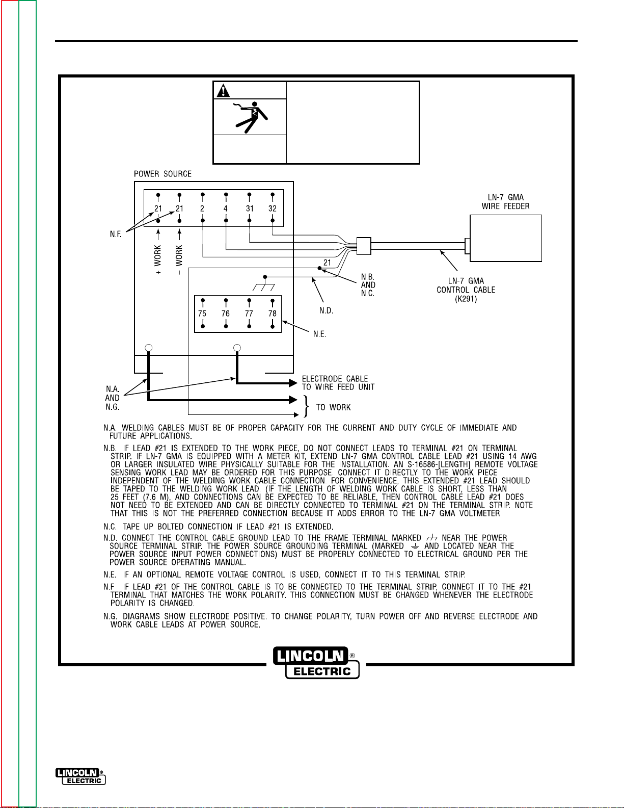
A.3 LN-7 GMA To DC-400, DC-250 and CV/CVI Power Sources With Terminal Strip - Connection
Diagram
A.4 LN-7 GMA To Pulsed Power 500 - Connection Diagram
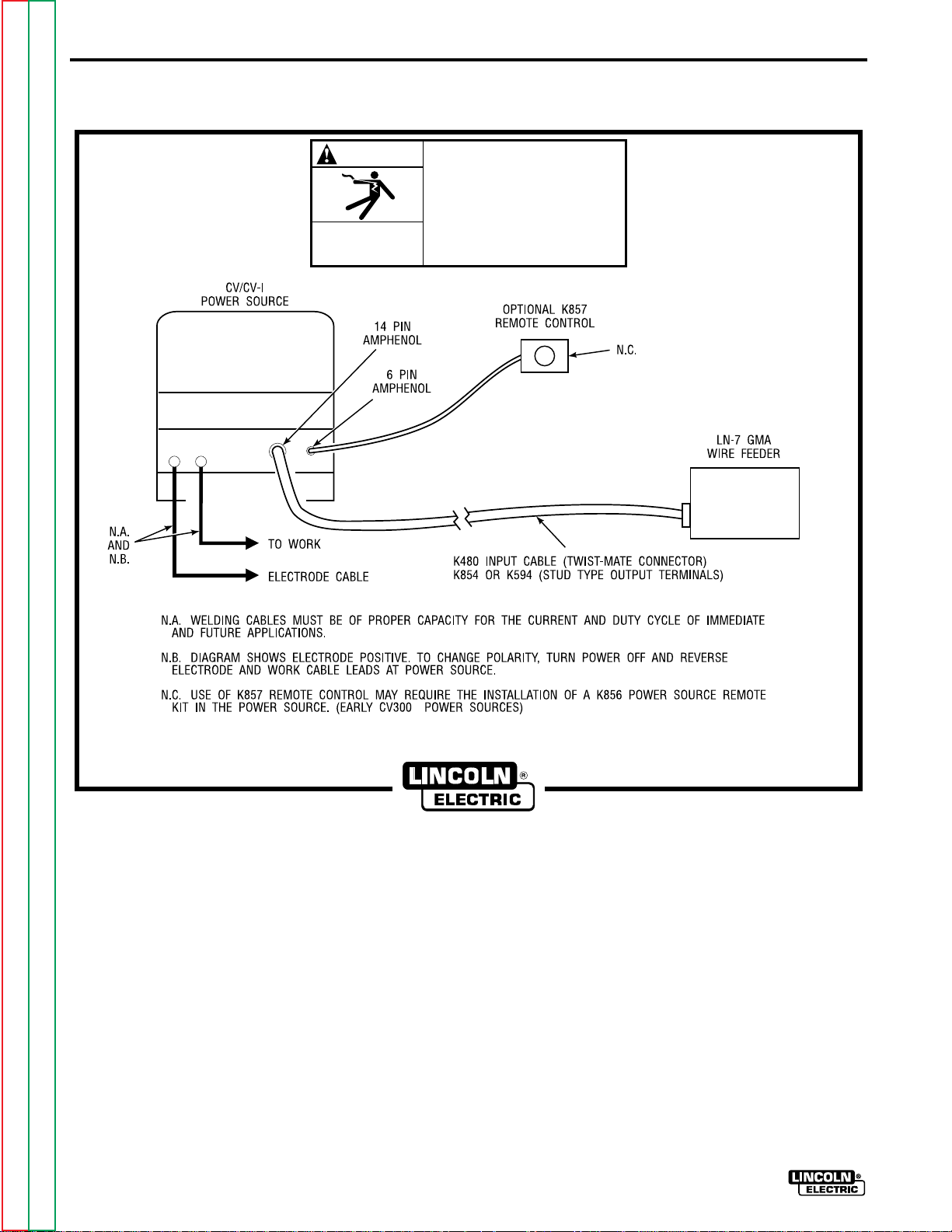
A.5 LN-7 GMA To CV/CVI Power Sources With 14 Pin Amphenol Connector - Connection Diagram
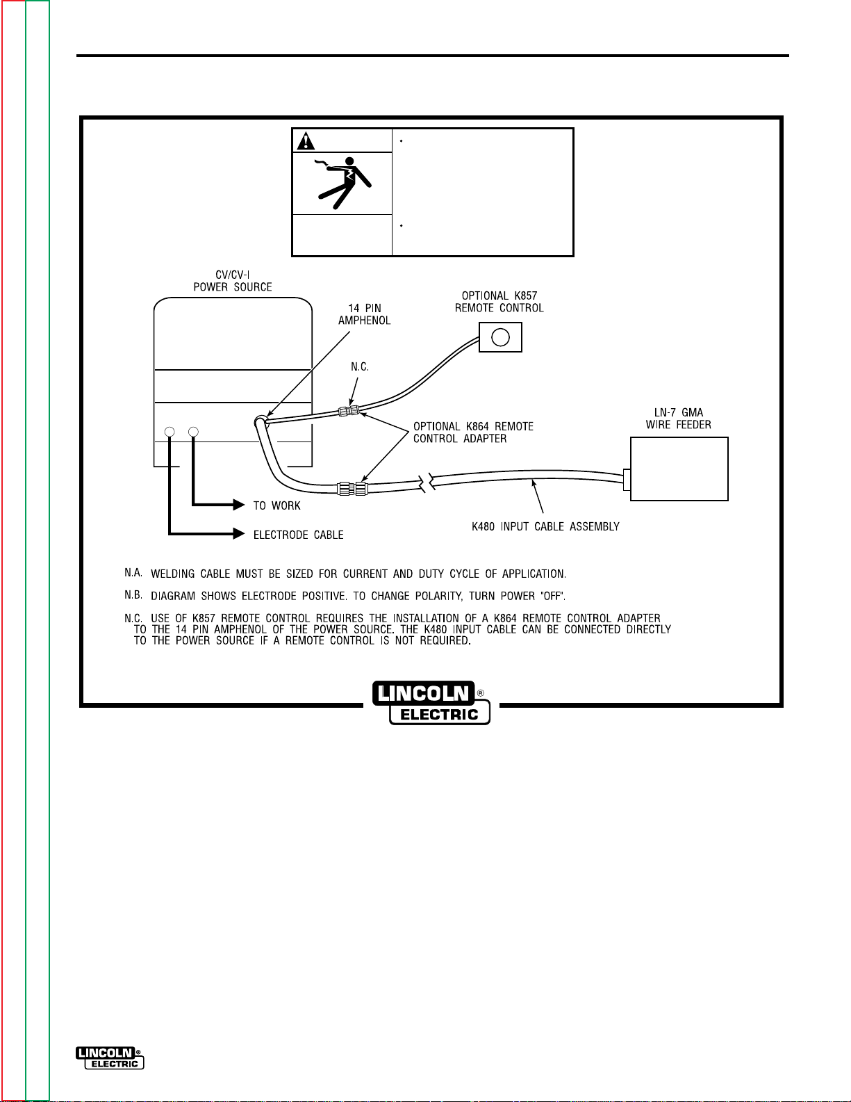
A.6 LN-7 GMA To CV/CVI Power Sources With Twist-Mate Connector and 14 Pin Amphenol/Remote
Control - Connection Diagram
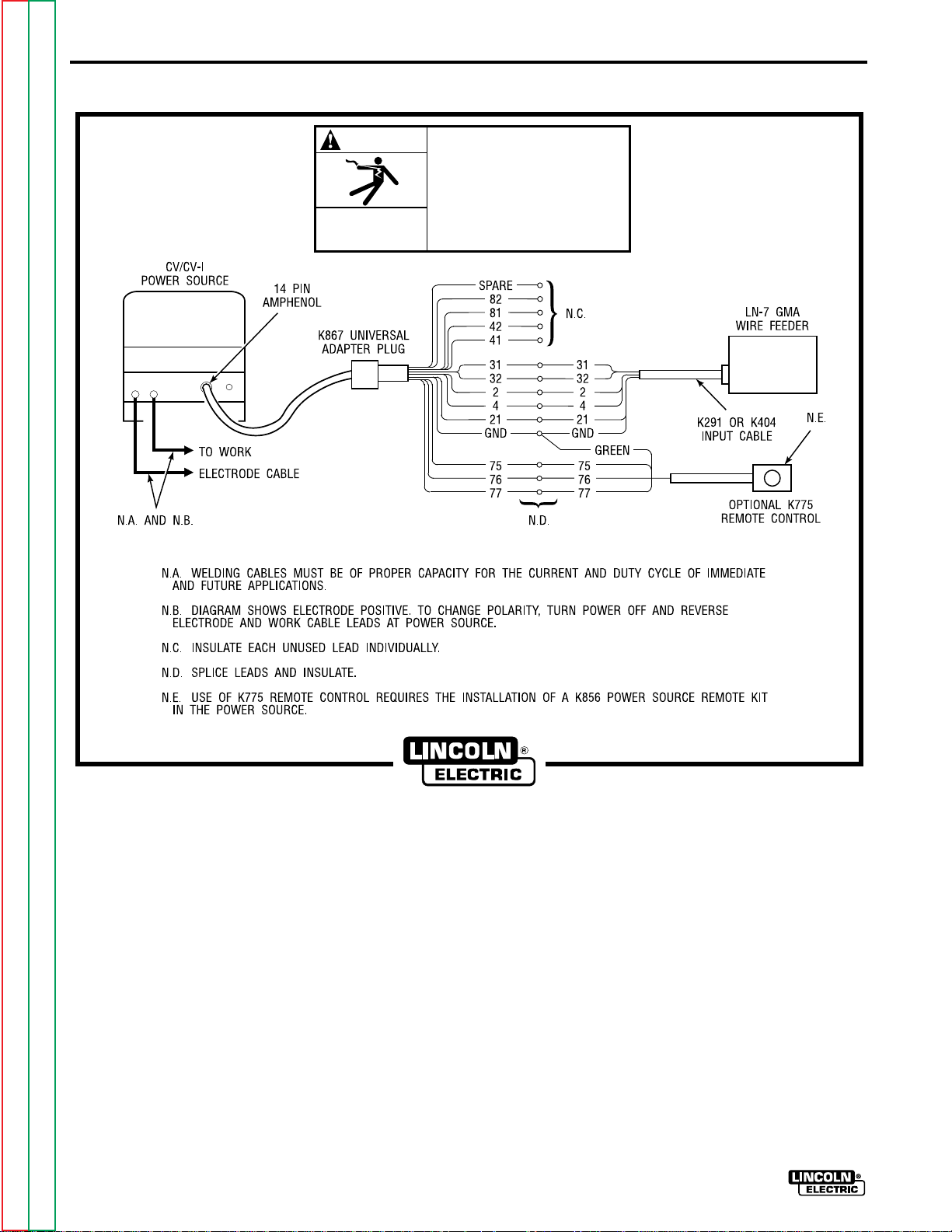
A.7 LN-7 GMA To CV/CVI Power Source (K867/K775) - Connection Diagram
A.8 LN-7 GMA To R3S-250 or R3S-325 - Connection Diagram
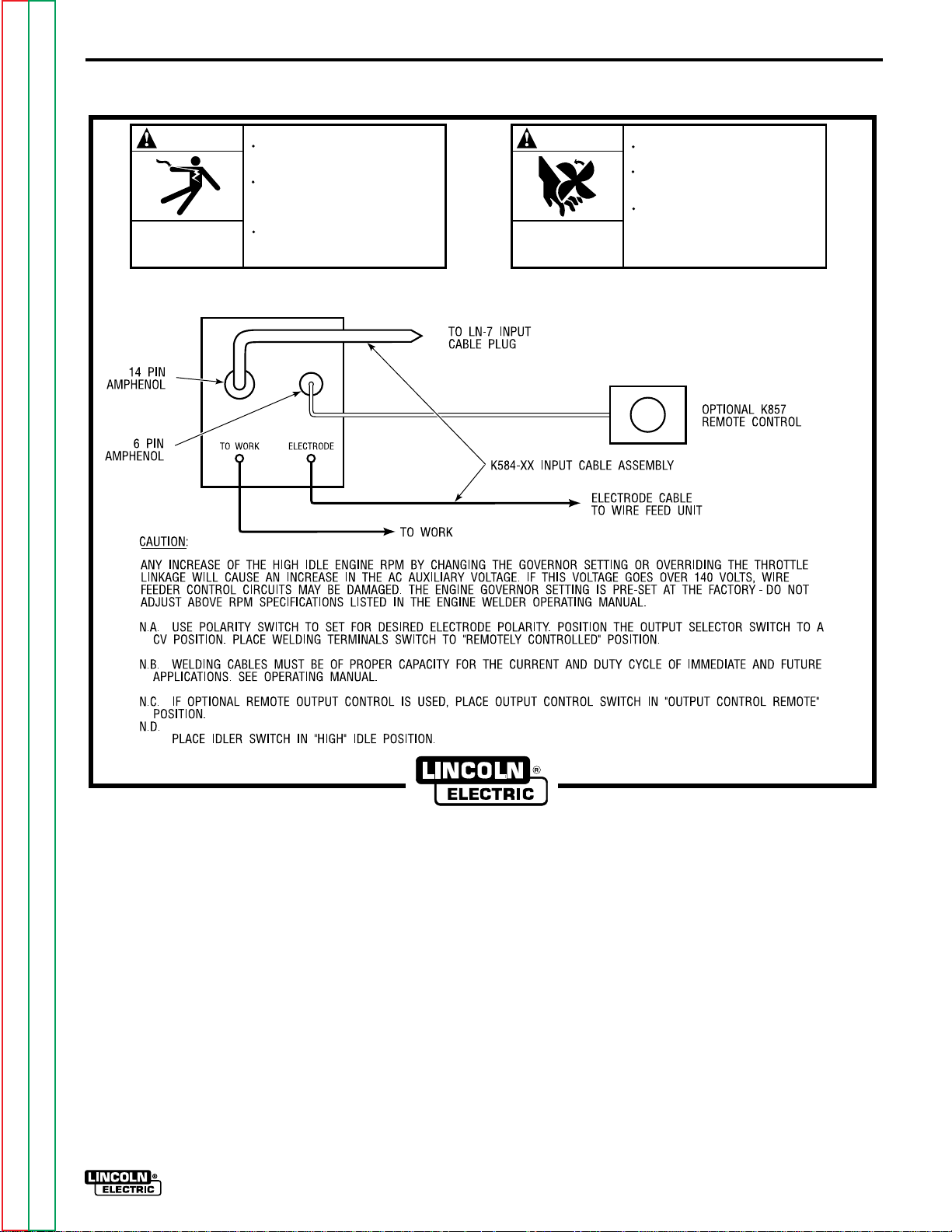
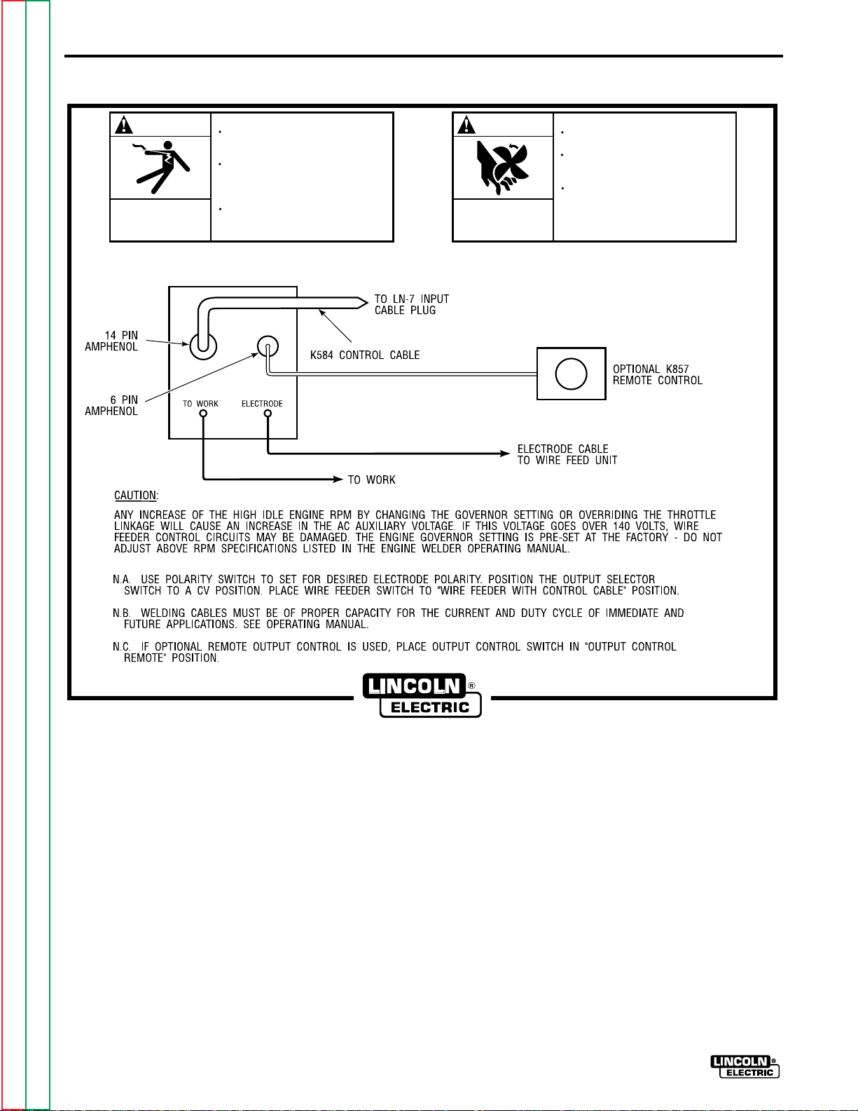
A.9 LN-7 GMA To SAM Motor Generator or Engine Welder - Connection Diagram
A.10 LN-7 GMA To DC-600 - Connection Diagram
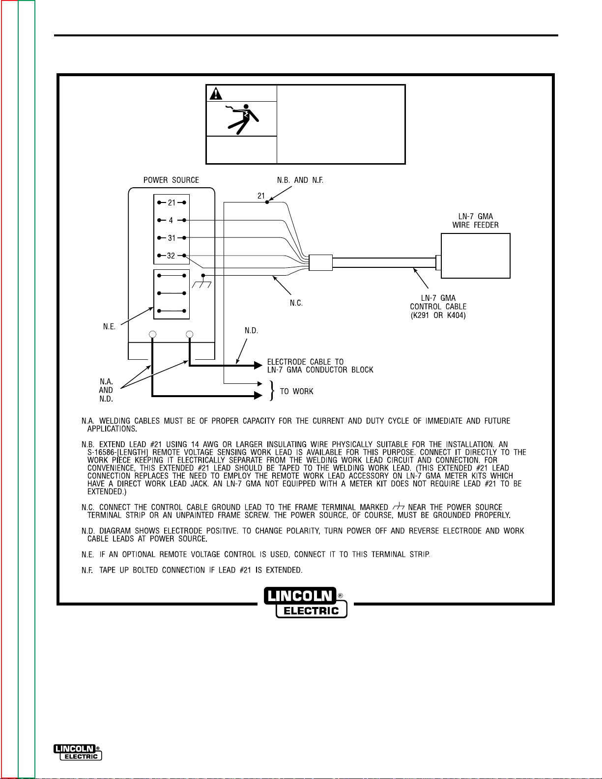
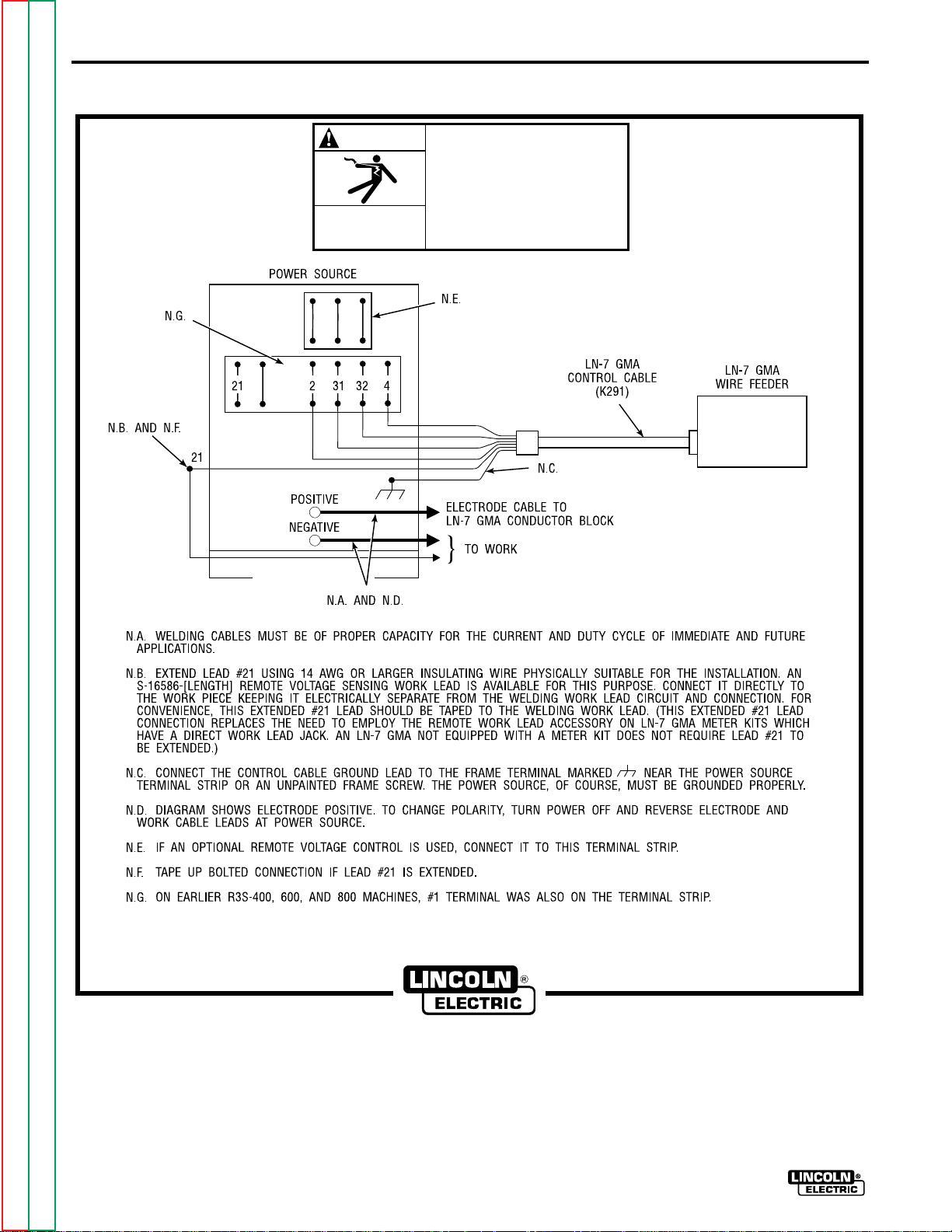
A.11 LN-7 GMA To R3S-400, 600, or 800 - Connection Diagram
A.12 LN-7 GMA To Most Lincoln Motor Generators - Connection Diagram
A.13 LN-7 GMA To WP250 or G9 PRO - Connection Diagram
A.14 LN-7 GMA To Ranger 9 - Connection Diagram
A.15 LN-7 GMA To Ranger 10-LX - Connection Diagram
A.16 LN-7 GMA To Power Sources With No Output Contactor - Connection Diagram
A.17 LN-7 GMA To Power Sources With Contactor and No Terminal Strip - Connection Diagram
Return to Master TOC Return to Master TOC Return to Master TOC Return to Master TOC
Return to Section TOC Return to Section TOC Return to Section TOC Return to Section TOC
LN-7 GMA WIRE FEEDER
Page 10
INSTALLATIONA-4
1. For K291 and K404 cables, connect the end of
the control cable with the lugged leads to the
power source. If lead #21 is extended to work, do
not connect leads to terminal #21 on terminal
strip. Include any jumpers called for on the
connection diagram. Do not add any other
jumpers or connections.
WARNING
Never operate a Lincoln power source that has a
jumper from #2 to #4 on the terminal strip, or a
power source without a contactor, with this wire
feeder. To do so would defeat the purpose of the
grounding lead protector circuit and could result in
the overheating of the electrical ground circuit to
the wire feeder.
2. For constant voltage power sources with an
output contactor but no terminal strip or 14-pin
control receptacle, see Figure A.14. For constant
voltage power sources without an internal output
contactor, and requiring a K240 Contactor Kit,
see Figure A.13.
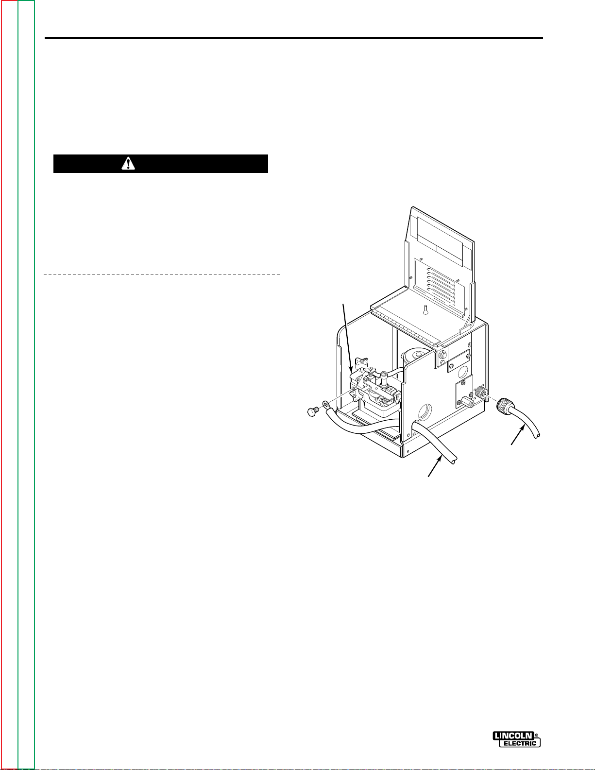
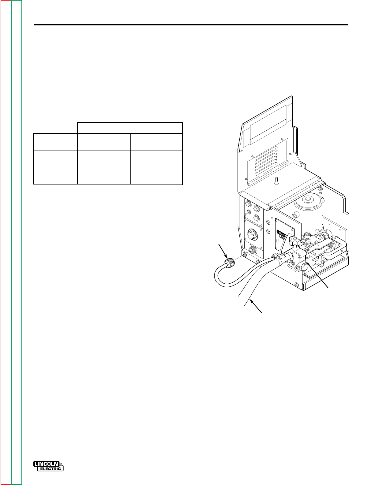
4. Referring to Figure A.1, route the end of the
electrode cable through the large hole in the back
panel of the LN-7 case. Connect the electrode
cable to the brass conductor block on the front of
the gearbox using the 1/2-13 x .75 bolt provided.
Be sure the cable is placed to allow easy
access and clearance for the idle roll arm
pressure adjustment and to allow the drive
roll section cover to close.
FIGURE A.1 – INPUT CONTROL CABLE AND
ELECTRODE CABLE CONNECTIONS.
CONDUCTOR
BLOCK
3. If input cables longer than the standard length
must be used, K292 extension cables (50 ft/15.2
m) can be installed. These have polarized plugs
on each end of the control cable and include a 4/0
(107 mm2) electrode cable. Install the extensions
between the standard input cable and the wire
feeder. Total input cable length should not exceed
400 ft (122 m). When using longer lengths of
extension cables, it may be necessary to add
parallel electrode cables to minimize the voltage
drop in the cable.
CONTROL
CABLE
ELECTRODE
Return to Master TOC Return to Master TOC Return to Master TOC Return to Master TOC
Return to Section TOC Return to Section TOC Return to Section TOC Return to Section TOC
LN-7 GMA WIRE FEEDER
Page 11

INSTALLATION A-5
5. Connect the input control cable polarized
Amphenol plug into the mating 6-pin receptacle
on the rear of the control section.
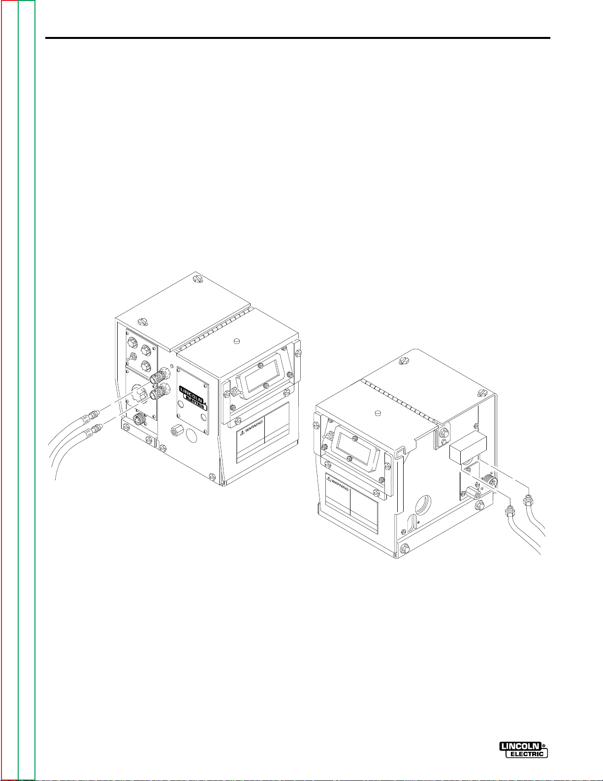
6. Referring to Figure A.2, install the input cable
under the wire reel mounting stand strain relief
FIGURE A.2 – STRAIN RELIEF CLAMP.
clamp. Remove the screws holding the clamp to
the base of the wire reel mounting assembly, put
the input cable assembly under the clamp and
reinstall the screws.
CONTROL
CABLE
STRAIN
RELIEF
CLAMP
ELECTRODE
CABLE
Return to Master TOC Return to Master TOC Return to Master TOC Return to Master TOC
Return to Section TOC Return to Section TOC Return to Section TOC Return to Section TOC
LN-7 GMA WIRE FEEDER
Page 12
A-6
INSTALLATION
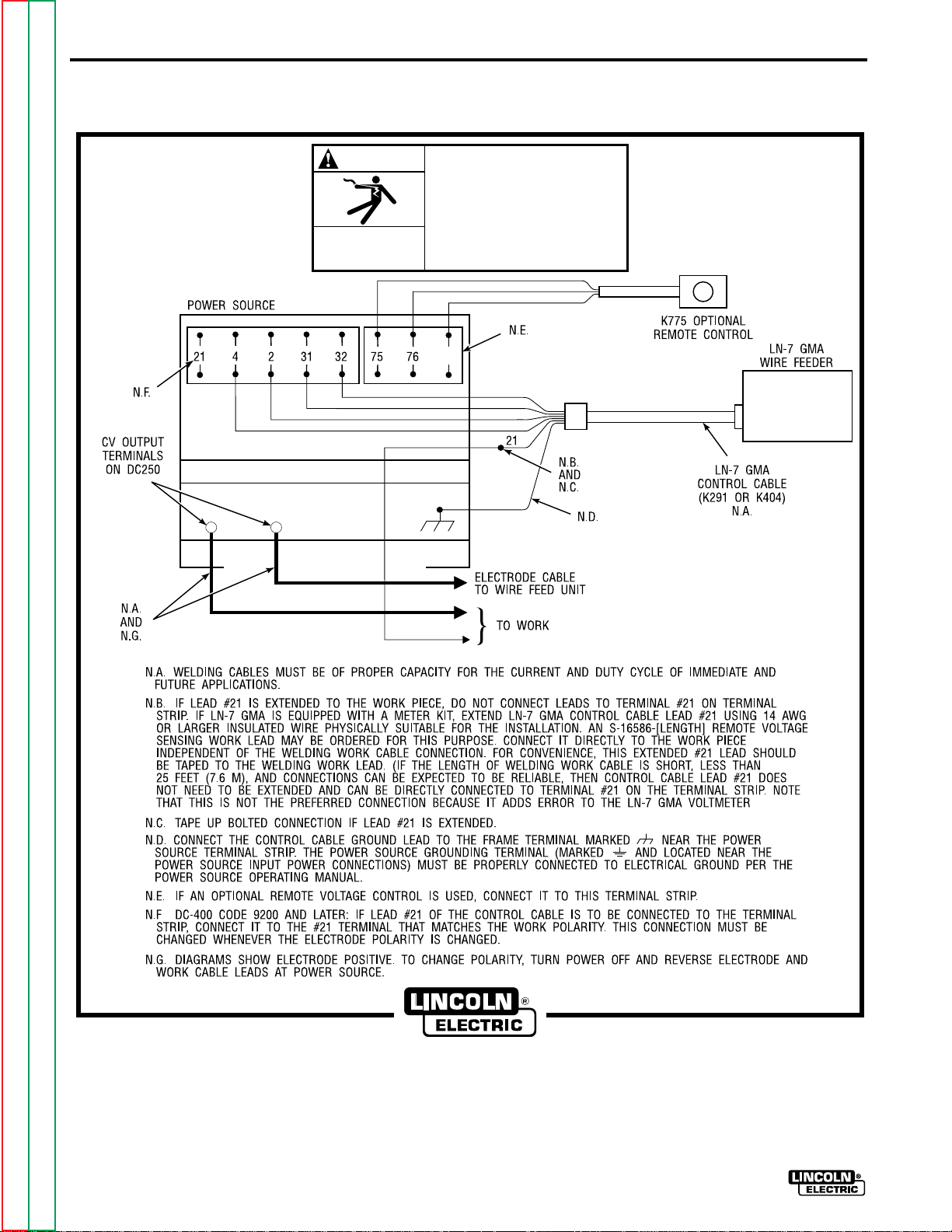
FIGURE A.3 – LN-7 GMA TO DC-400, DC-250 AND CV/CVI POWER SOURCES WITH
TERMINAL STRIP - CONNECTION DIAGRAM.
WARNING
ELECTRIC
SHOCK
CAN KILL
–
+
TURN INPUT POWER OFF
BEFORE CONNECTING THE
LN-7 GMA WIRE FEEDER.
77
Return to Master TOC Return to Master TOC Return to Master TOC Return to Master TOC
Return to Section TOC Return to Section TOC Return to Section TOC Return to Section TOC
LN-7 GMA WIRE FEEDER
CLEVELAND, OHIO U.S.A
Page 13
INSTALLATION A-7
FIGURE A.4 – LN-7 GMA TO PULSED POWER 500 - CONNECTION DIAGRAM.
WARNING
ELECTRIC
SHOCK
CAN KILL
–
+
TURN INPUT POWER OFF
BEFORE CONNECTING THE
LN-7 GMA WIRE FEEDER.
Return to Master TOC Return to Master TOC Return to Master TOC Return to Master TOC
Return to Section TOC Return to Section TOC Return to Section TOC Return to Section TOC
CLEVELAND, OHIO U.S.A
LN-7 GMA WIRE FEEDER
Page 14
A-8
INSTALLATION
FIGURE A.5 – LN-7 GMA TO CV/CVI POWER SOURCES WITH 14 PIN AMPHENOL
CONNECTOR - CONNECTION DIAGRAM.
WARNING
ELECTRIC
SHOCK
CAN KILL
+
–
TURN INPUT POWER OFF
BEFORE CONNECTING THE
LN-7 GMA WIRE FEEDER.
Return to Master TOC Return to Master TOC Return to Master TOC Return to Master TOC
Return to Section TOC Return to Section TOC Return to Section TOC Return to Section TOC
LN-7 GMA WIRE FEEDER
CLEVELAND, OHIO U.S.A
Page 15
INSTALLATION A-9
FIGURE A.6 – LN-7 GMA TO CV/CVI POWER SOURCES WITH TWIST-MATE CONNECTOR
AND 14 PIN AMPHENOL/REMOTE CONTROL - CONNECTION DIAGRAM.
WARNING
ELECTRIC
SHOCK
CAN KILL
+
–
TURN OFF INPUT POWER
TO THE WELDING POWER
SOURCE USING THE
DISCONNECT SWITCH AT
THE FUSE BOX BEFORE
CONNECTING THE WIRE
FEEDER.
ONLY QUALIFIED PERSONS
SHOULD INSTALL, USE, OR
SERVICE THIS MACHINE.
Return to Master TOC Return to Master TOC Return to Master TOC Return to Master TOC
Return to Section TOC Return to Section TOC Return to Section TOC Return to Section TOC
CLEVELAND, OHIO U.S.A
LN-7 GMA WIRE FEEDER
Page 16
INSTALLATIONA-10
FIGURE A.7 – LN-7 GMA TO CV/CVI POWER SOURCE (K867/K775) - CONNECTION DIAGRAM.
WARNING
ELECTRIC
SHOCK
CAN KILL
–+
TURN INPUT POWER OFF
BEFORE CONNECTING THE
LN-7 GMA WIRE FEEDER.
Return to Master TOC Return to Master TOC Return to Master TOC Return to Master TOC
Return to Section TOC Return to Section TOC Return to Section TOC Return to Section TOC
LN-7 GMA WIRE FEEDER
CLEVELAND, OHIO U.S.A
Page 17
INSTALLATION A-11
FIGURE A.8 – LN-7 GMA TO R3S-250 OR R3S-325 - CONNECTION DIAGRAM.
–+
WARNING
ELECTRIC
SHOCK
CAN KILL
TURN INPUT POWER OFF
BEFORE CONNECTING THE
LN-7 GMA WIRE FEEDER.
Return to Master TOC Return to Master TOC Return to Master TOC Return to Master TOC
Return to Section TOC Return to Section TOC Return to Section TOC Return to Section TOC
CLEVELAND, OHIO U.S.A
LN-7 GMA WIRE FEEDER
Page 18

INSTALLATIONA-12
FIGURE A.9 – LN-7 GMA TO SAM MOTOR GENERATOR OR ENGINE WELDER - CONNECTION DIAGRAM.
WARNING
ELECTRIC
SHOCK
CAN KILL
TURN INPUT POWER OFF
BEFORE CONNECTING THE
LN-7 GMA WIRE FEEDER.
Return to Master TOC Return to Master TOC Return to Master TOC Return to Master TOC
Return to Section TOC Return to Section TOC Return to Section TOC Return to Section TOC
LN-7 GMA WIRE FEEDER
CLEVELAND, OHIO U.S.A
Page 19

INSTALLATION A-13
FIGURE A.10 – LN-7 GMA TO DC-600 - CONNECTION DIAGRAM.
WARNING
ELECTRIC
SHOCK
CAN KILL
–
+
TURN INPUT POWER OFF
BEFORE CONNECTING THE
LN-7 GMA WIRE FEEDER.
Return to Master TOC Return to Master TOC Return to Master TOC Return to Master TOC
Return to Section TOC Return to Section TOC Return to Section TOC Return to Section TOC
CLEVELAND, OHIO U.S.A
LN-7 GMA WIRE FEEDER
Page 20
INSTALLATIONA-14
FIGURE A.11 – LN-7 GMA TO R3S-400, 600, OR 800 - CONNECTION DIAGRAM.
WARNING
ELECTRIC
SHOCK
CAN KILL
TURN INPUT POWER OFF
BEFORE CONNECTING THE
LN-7 GMA WIRE FEEDER.
Return to Master TOC Return to Master TOC Return to Master TOC Return to Master TOC
Return to Section TOC Return to Section TOC Return to Section TOC Return to Section TOC
LN-7 GMA WIRE FEEDER
CLEVELAND, OHIO U.S.A
Page 21

INSTALLATION A-15
FIGURE A.12 – LN-7 GMA TO MOST LINCOLN MOTOR GENERATORS - CONNECTION DIAGRAM.
32
WARNING
ELECTRIC
SHOCK
CAN KILL
TURN INPUT POWER OFF
BEFORE CONNECTING THE
LN-7 GMA WIRE FEEDER.
Return to Master TOC Return to Master TOC Return to Master TOC Return to Master TOC
Return to Section TOC Return to Section TOC Return to Section TOC Return to Section TOC
CLEVELAND, OHIO U.S.A
LN-7 GMA WIRE FEEDER
Page 22

INSTALLATIONA-16
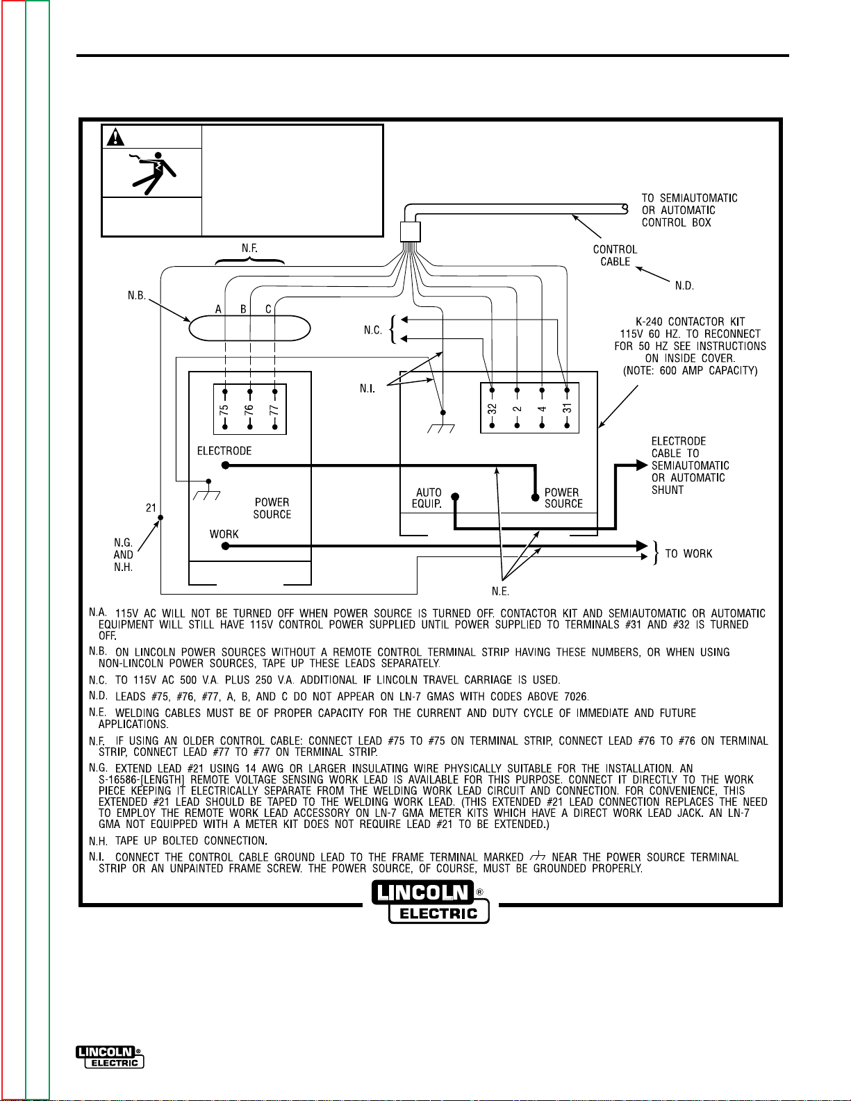
FIGURE A.13 – LN-7 GMA TO WP250 OR G9 PRO - CONNECTION DIAGRAM.
WARNING
ELECTRIC
SHOCK
CAN KILL
TURN INPUT POWER OFF
BEFORE CONNECTING THE
LN-7 GMA WIRE FEEDER.
CAUTION
AUXILIARY
VOLTAGE MUST
NOT EXCEED
140 VOLTS.
LN-7 GMA TO WP250 G9
PRO: ANY INCREASE OF THE
HIGH IDLE ENGINE RPM BY
CHANGING THE GOVERNOR
SETTING OR OVERRIDING
THE THROTTLE LINKAGE
WILL CAUSE AN INCREASE
IN THE AC AUXILIARY
VOLTAGE. IF THIS VOLTAGE
GOES ABOVE 140 VOLTS,
THE LN-7 GMA CONTROL
CIRCUIT WILL BE DAMAGED.
THE ENGINE GOVERNOR
SETTING IS PRE-SET AT THE
FACTORY - DO NOT ADJUST
ABOVE RPM SPECIFICATIONS
LISTED IN ENGINE WELDER
OPERATING MANUAL.
Return to Master TOC Return to Master TOC Return to Master TOC Return to Master TOC
Return to Section TOC Return to Section TOC Return to Section TOC Return to Section TOC
LN-7 GMA WIRE FEEDER
CLEVELAND, OHIO U.S.A
Page 23
INSTALLATION A-17
FIGURE A.14 – LN-7 GMA TO RANGER 9 – CONNECTION DIAGRAM.
WARNING
ELECTRIC
SHOCK
CAN KILL
DO NOT OPERATE WITH
PANELS OPEN.
DISCONNECT NEGATIVE (-)
BATTERY LEAD BEFORE
SERVICING.
DO NOT TOUCH
ELECTRICALLY LIVE PARTS.
WARNING
MOVING
PARTS
CAN INJURE
KEEP GUARDS IN PLACE.
KEEP AWAY FROM MOVING
PAR TS.
ONLY QUALIFIED PERSONS
SHOULD INSTALL, USE, OR
SERVICE THIS MACHINE.
Return to Master TOC Return to Master TOC Return to Master TOC Return to Master TOC
Return to Section TOC Return to Section TOC Return to Section TOC Return to Section TOC
CLEVELAND, OHIO U.S.A
LN-7 GMA WIRE FEEDER
Page 24
INSTALLATIONA-18
FIGURE A.15 – LN-7 GMA TO RANGER 10-LX – CONNECTION DIAGRAM.
WARNING
ELECTRIC
SHOCK
CAN KILL
DO NOT OPERATE WITH
PANELS OPEN.
DISCONNECT NEGATIVE (-)
BATTERY LEAD BEFORE
SERVICING.
DO NOT TOUCH
ELECTRICALLY LIVE PARTS.
WARNING
MOVING
PARTS
CAN INJURE
KEEP GUARDS IN PLACE.
KEEP AWAY FROM MOVING
PAR TS.
ONLY QUALIFIED PERSONS
SHOULD INSTALL, USE, OR
SERVICE THIS MACHINE.
Return to Master TOC Return to Master TOC Return to Master TOC Return to Master TOC
Return to Section TOC Return to Section TOC Return to Section TOC Return to Section TOC
LN-7 GMA WIRE FEEDER
CLEVELAND, OHIO U.S.A
Page 25
INSTALLATION A-19
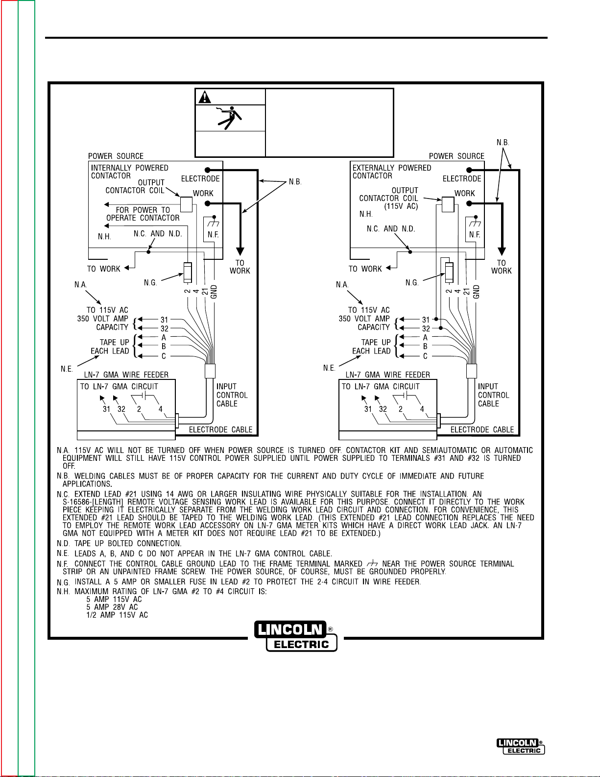
FIGURE A.16 – LN-7 GMA TO POWER SOURCES WITH NO OUTPUT
CONTACTOR - CONNECTION DIAGRAM.
WARNING
ELECTRIC
SHOCK
CAN KILL
TURN INPUT POWER OFF
BEFORE CONNECTING THE
LN-7 GMA WIRE FEEDER.
Return to Master TOC Return to Master TOC Return to Master TOC Return to Master TOC
Return to Section TOC Return to Section TOC Return to Section TOC Return to Section TOC
CLEVELAND, OHIO U.S.A
LN-7 GMA WIRE FEEDER
Page 26
INSTALLATIONA-20
FIGURE A.17 – LN-7 GMA TO POWER SOURCES WITH CONTACTOR AND NO TERMINAL
STRIP - CONNECTION DIAGRAM.
WARNING
ELECTRIC
SHOCK
CAN KILL
TURN INPUT POWER OFF
BEFORE CONNECTING THE
LN-7 GMA WIRE FEEDER.
Return to Master TOC Return to Master TOC Return to Master TOC Return to Master TOC
Return to Section TOC Return to Section TOC Return to Section TOC Return to Section TOC
LN-7 GMA WIRE FEEDER
CLEVELAND, OHIO U.S.A
Page 27
INSTALLATION A-21
WORK CABLE
Connect a work lead of sufficient size and length (Table
A.2) between the proper output stud on the power
source and the work. Be sure the connection to the
work makes tight metal-to-metal electrical contact.
Poor work lead connections can result in the grounding
lead protector being activated.
TABLE A.2 – WORK LEAD SPECIFICATIONS
Copper Work Cable Size, AWG
Current 60% Up To 50 Ft 50 Ft-100 Ft
Duty Cycle (15.2 m2) (15.2-30.4 m2)
300 Amps 0 (53 mm2) 00 (67 mm2)
400 Amps 00 (67 mm2) 000 (85 mm2)
500 Amps 00 (67 mm2) 000 (85 mm2)
600 Amps 000 (85 mm2) 0000 (107 mm2)
GUN AND CABLE ASSEMBLIES
Connect the control cable amphenol plug into the
mating 5-cavity receptacle on the front of the control
section below the nameplate.
If using the K489-1 Fast-Mate Adapter, install per the
S19389 instructions included with the kit.
FIGURE A.18 – GUN CABLE CONNECTIONS.
The LN-7 GMA can be used with several guns. In most
cases, Lincoln guns and cables are shipped
assembled, ready to weld. Use the gun and cable
assembly for the electrode type (solid, Outershield , or
Innershield) and electrode size to be used. Refer to the
Accessories Section for different gun types.
GUN CABLE CONNECTIONS
Lay the cable out straight. Insert the connector on the
welding conductor cable through the large hole in the
front panel of the LN-7 GMA and into the brass
conductor block on the front of the gearbox. Refer to
Figure A.18. Make sure it is all the way in and tighten
the hand wheel. Keep this connection clean and bright.
AMPHENOL
CONNECTOR
CONDUCTOR
BLOCK
GUN CABLE
ASSEMBLY
Return to Master TOC Return to Master TOC Return to Master TOC Return to Master TOC
Return to Section TOC Return to Section TOC Return to Section TOC Return to Section TOC
LN-7 GMA WIRE FEEDER
Page 28
A-22
INSTALLATION
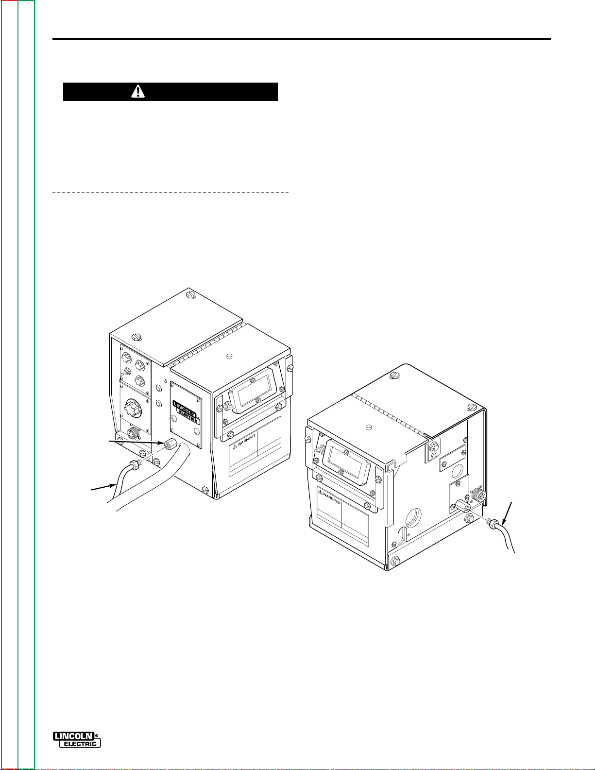
WATER CONNECTIONS
(FOR WATER COOLED GUNS)
The LN-7 GMA must have a K527 Water Solenoid Kit
installed (see the Accessories Section). The K440-1
LN-7 GMA model already has a water solenoid
installed. Refer to Figure A.19 and perform the
following steps:
NOTE: If not using a Lincoln water cooler (such as the
K877-1), and if your water cooling device is not
designed for use with a waterline solenoid valve, you
may remove the solenoid and screw the male fitting
(after applying sealant) directly into the brass manifold
block.
FIGURE A.19 – WATER CONNECTIONS.
1. Using male 5/8-18 UNF left-hand thread fittings,
connect appropriate water hoses to the coolant
inlet and outlet on the back of the LN-7 GMA.
Connect the other ends of these hoses to the
appropriate ports on your water cooling units.
2. In the event the water line fittings on your water
cooled gun are incompatible with the female quick
connects on the front of the LN-7 GMA, male
quick connects are provided for installation on
3/16 in. I.D. hose (customer to provide
appropriate clamps). The feeder connectors self
seal when disconnected.
Return to Master TOC Return to Master TOC Return to Master TOC Return to Master TOC
Return to Section TOC Return to Section TOC Return to Section TOC Return to Section TOC
LN-7 GMA WIRE FEEDER
FRONT
BACK
Page 29
INSTALLATION A-23
SHIELDING GAS HOOKUP
WARNING
Gas under pressure is explosive. Always keep gas
cylinders in an upright position and to the
undercarriage or a stationary support. See
American National Standard Z-49.1, “Safety In
Welding And Cutting”, published by the American
Welding Society.
Customer must provide a cylinder of shielding gas, a
pressure regulator, a flow control valve, and a hose
from the flow valve to the gas inlet fitting of the LN-7
FIGURE A.20 – SHIELDING GAS HOOKUP.
GMA or the K494 Gas Solenoid Valve Kit installed on
the LN-7 GMA. Install per Figure A.20 and the
following:
1. Connect the supply hose from the gas cylinder
flow valve outlet to the 5/8-18 female inert gas
fitting on the back panel of the LN-7 GMA.
2. Install the barbed fitting and union nut to the
5/8-18 female inert gas fitting on the front of the
LN-7 GMA. Connect 3/16 in. (4.8 mm) I.D. gas
hose from the gun to the barbed fitting.
When the gun is to be removed, this fitting can be
easily detached by loosening the union nut.
INERT
FITTING
GAS
HOSE
GAS
GAS
SUPPLY
HOSE
Return to Master TOC Return to Master TOC Return to Master TOC Return to Master TOC
Return to Section TOC Return to Section TOC Return to Section TOC Return to Section TOC
LN-7 GMA WIRE FEEDER
Page 30

A-24 NOTES
Return to Master TOC Return to Master TOC Return to Master TOC Return to Master TOC
Return to Section TOC Return to Section TOC Return to Section TOC Return to Section TOC
LN-7 GMA WIRE FEEDER
Page 31

TABLE OF CONTENTS
- OPERATION SECTION -
Operation . . . . . . . . . . . . . . . . . . . . . . . . . . . . . . . . . . . . . . . . . . . . . . . . . Section B
Operating Instructions . . . . . . . . . . . . . . . . . . . . . . . . . . . . . . . . . . . . . B-2
Safety Precautions . . . . . . . . . . . . . . . . . . . . . . . . . . . . . . . . . . . . . . . . B-2
General Description . . . . . . . . . . . . . . . . . . . . . . . . . . . . . . . . . . . . . . . B-2
Recommended Processes and Equipment . . . . . . . . . . . . . . . . . . . . . . B-2
Controls and Settings . . . . . . . . . . . . . . . . . . . . . . . . . . . . . . . . . . . . . . B-3
Circuit Protection . . . . . . . . . . . . . . . . . . . . . . . . . . . . . . . . . . . . . . . . . B-4
Avoiding Ground Lead Protector (GLP) Activation . . . . . . . . . . . . . . . . . B-4
Drive Roll Installation . . . . . . . . . . . . . . . . . . . . . . . . . . . . . . . . . . . . . . B-4
Changing Drive Rolls For Two-Roll Wire Feeders . . . . . . . . . . . . . . B-4
Changing Drive Rolls For Four-Roll Wire Feeders . . . . . . . . . . . . . B-6
Idle Roll Pressure Setting . . . . . . . . . . . . . . . . . . . . . . . . . . . . . . . . . . . B-8
Wire Loading . . . . . . . . . . . . . . . . . . . . . . . . . . . . . . . . . . . . . . . . . . . . B-9
Wire Reel Loading - Readi-Reels and Spools . . . . . . . . . . . . . . . . . B-9
Wire Reel Loading - 50 and 60 lb Coils . . . . . . . . . . . . . . . . . . . . . B-11
Wire Loading - 13-14 lb Innershield Coils . . . . . . . . . . . . . . . . . . . . B-12
Acceleration Setting . . . . . . . . . . . . . . . . . . . . . . . . . . . . . . . . . . . . . . . B-13
Wire Speed and Voltage Adjustment . . . . . . . . . . . . . . . . . . . . . . . . . . . B-13
Making a Weld . . . . . . . . . . . . . . . . . . . . . . . . . . . . . . . . . . . . . . . . . . . B-14
Wire Reel Changing . . . . . . . . . . . . . . . . . . . . . . . . . . . . . . . . . . . . . . . B-14
Optional K416 Analog and K417 Digital Voltmeter Kits . . . . . . . . . . . . . B-14
Flux Tank Loading . . . . . . . . . . . . . . . . . . . . . . . . . . . . . . . . . . . . . . . . B-15
K320 Flux Tank (Optional) . . . . . . . . . . . . . . . . . . . . . . . . . . . . . . . B-15
K310 Flux Screen (Optional) . . . . . . . . . . . . . . . . . . . . . . . . . . . . . B-15
K58 Magnetic Separator (Optional) . . . . . . . . . . . . . . . . . . . . . . . . . B-15
Section B
Return to Master TOC Return to Master TOC Return to Master TOC Return to Master TOC
LN-7 GMA WIRE FEEDER
Page 32

OPERATIONB-2
OPERATING INSTRUCTIONS
Read and understand the entire Operation Section
prior to operating the machine.
SAFETY PRECAUTIONS
WARNING
ELECTRIC SHOCK
can kill.
• Do not touch electrically live parts
or electrode with skin or wet
clothing.
• Insulate yourself from work or
ground.
• Always wear dry insulating
gloves.
FUMES AND GASES
can be dangerous.
• Keep your head out of fumes.
• Use ventilation or exhaust to
remove fumes from breathing
zone.
GENERAL DESCRIPTION
The K440 LN-7 GMA semiautomatic constant speed
wire feeder is specifically equipped for gas metal arc
welding using flux-cored Outershield electrodes and
solid wire. The LN-7 GMA is also suitable for selfshielded flux-cored Innershield electrodes, submerged
arc welding (if constant voltage is satisfactory), and
other open arc welding. It has been factory assembled
with the following features:
• Calibrated wire feed dial [75 to 700 in./min (1.9 to
17.8 m/min)].
• Factory installed gas solenoid valve and gas fittings.
• Wire drive uses a permanent magnet motor and
includes tool-less “quick- release” idle roll pressure
arm, outgoing guide tube and gun cable fastening.
• Optional factory installed water solenoid and fittings
for use with water cooled welding guns.
The K567-1 LN-7 GMA 4-Roll is designed to provide
the additional feeding force required when using gun
cables over 15 ft (4.6 m) long or when the wire is pulled
long distances (such as when bulk packages are
used). Because the four-roll feeder has twice the
contact surface, it can also help when feeding softer
wires by delivering the same or more feeding force as
the two-roll with less overall wire deformation. Wire
size range, speed and features are the same as other
LN-7 GMA models.
Observe additional Safety Guidelines detailed in
the beginning of this manual.
Return to Master TOC Return to Master TOC Return to Master TOC Return to Master TOC
Return to Section TOC Return to Section TOC Return to Section TOC Return to Section TOC
WELDING SPARKS
can cause fire or explosion.
• Keep flammable material away.
• Do not weld on containers that
have held combustibles.
ARC RAYS
can burn.
• Wear eye, ear, and body
protection.
RECOMMENDED PROCESSES AND
EQUIPMENT
The LN-7 GMA is recommended for use in MIG and
Innershield welding applications with constant voltage
power sources such as the Idealarc DC-250, 400, or
600, or CV types. The LN-7 is capable of feeding wires
ranging from 0.023 in. through 1/16 in. (0.6 through
1.6 mm) solid, 0.045 in. through 5/64 in. (1.2 through
2.0 mm) Innershield, and 0.062 in. through 5/64 in.
(1.6 through 2.0 mm) Outershield electrodes.
LN-7 GMA WIRE FEEDER
Page 33

OPERATION B-3
CONTROLS AND SETTINGS
Operator controls are illustrated in Figure B.1. Refer to
the figure and the following explanations of the
controls.
WIRE FEED SPEED CONTROL. This control sets the
feed speed of the wire feeder. Turn the knob to the left
for slower speeds and to the right for higher speeds.
The control is calibrated. The nameplate shows the
wire speed for the given setting of the control.
BURNBACK CONTROL (OPTIONAL). This control,
located on the optional K419 Burnback Timer and K418
GMA Timer Kits, provides a precise time delay that
allows the wire to be burned off at the end of the weld.
This is useful for those applications where higher
speed, fine wire feeding is used and there is a
tendency for the electrode to overrun at the end of the
weld and cause “sticking” in the crater. The delay is
adjustable for optimum burnback depending on wire
size, process, procedure, etc.
PREFLOW CONTROL (OPTIONAL). This control,
located on the optional K418 GMA Timer Kit, provides
flow of shielding gas to the work before the arc is
established. The gas solenoid valve is energized
immediately when the gun trigger is closed, but the
time delay before the wire feeder is energized is
adjustable from 0 to 1.5 seconds. Turn the knob to the
left for shorter delays and to the right for longer delays.
POSTFLOW CONTROL (OPTIONAL). This control,
located on the optional K418 GMA Timer Kit, provides
flow of shielding gas to the work after welding has
stopped. Delay for the gas solenoid valve shutoff is
adjustable from 0 to 1.5 seconds. Turn the knob to the
left for shorter delays and to the right for longer delays.
PURGE - COLD INCH SWITCH (OPTIONAL). This
control, located on the optional K418 GMA Timer Kit,
provides control of some wire feeder functions without
energizing the welding power source. The momentary
up position energizes the gas solenoid but not the wire
feeder or welding power source. The momentary down
position energizes the wire feeder but not the gas
solenoid or the welding power source.
ELECTRODE POLARITY SWITCH (OPTIONAL). This
switch, located on the optional K416 Digital and K417
Analog Meter Kits, controls the polarity of the meter.
Set this switch to the same polarity as the electrode
lead to allow correct operation of the meter.
PREFLOW
CONTROL
(OPTIONAL)
PURGE-COLD
INCH SWITCH
(OPTIONAL)
BURNBACK
CONTROL
(OPTIONAL)
WIRE FEED
SPEED CONTROL
FIGURE B.1 – WIRE FEEDER CONTROLS.
POSTFLOW
CONTROL
(OPTIONAL)
ELECTRODE
POLARITY SWITCH
(OPTIONAL)
Return to Master TOC Return to Master TOC Return to Master TOC Return to Master TOC
Return to Section TOC Return to Section TOC Return to Section TOC Return to Section TOC
LN-7 GMA WIRE FEEDER
Page 34

OPERATIONB-4
CIRCUIT PROTECTION
A manual reset circuit breaker protects the AC supply
line and the wire feeder from overloads, usually caused
by excessive wire drag or other wire feed problems. To
reset the circuit breaker, raise the cover of the wire
drive compartment and push the white button on the
side of the control box above the drive rolls. If the
circuit breaker trips again, refer to the Troubleshooting
Section.
The LN-7 GMA also includes a Ground Lead Protector
(GLP) circuit and fuse in the 2-4 contactor circuit. See
the Theory of Operation Section for a description of
these circuits.
AVOIDING GROUND LEAD
PROTECTOR (GLP) ACTIVATION
DO NOT allow the electrode to contact the case of the
wire feeder or the uninsulated part of the wire reel
stand when the gun trigger is activated.
Be sure that all work lead connections to the work
make tight metal-to-metal contact.
DO NOT allow excess input cable or work cable to be
placed closer than three feet from the wire feeder.
DO NOT coil excess input cable assembly or use a
coiled assembly as shipped from the factory. Instead,
loop the excess cable length back and forth in three to
six foot straight lengths. Coiling the input cable results
in a transformer action between the electrode
conductor cable and the ground lead in the
multiconductor control cable. This transformer action
can cause a current to flow in the ground lead which
will falsely activate the GLP circuit.
DRIVE ROLL INSTALLATION
CHANGING DRIVE ROLLS FOR TWOROLL WIRE FEEDERS:
To change drive rolls on a two-roll wire feeder, refer to
Figure B.2 and perform the following steps:
1. Rotate the latch knob on the quick release arm.
2. Remove the hex head screw and clamping collar.
Remove the drive roll from the shaft. On new
machines, remove the tape and the drive key.
3. The new roll to be installed is stamped for the size to
be fed. An “A” after the size indicates aluminum wire.
Remove the rolls from the kit and wipe them clean.
Wipe the output shaft and locating shoulder clean.
4. Use the drive key, clamping collar, and hex head
screw to install the roll on the output shaft. Certain
size drive rolls consist of two roll halves, and may
contain a spacer. If the drive roll you are installing
contains a spacer, the spacer fits between the two
halves of the drive roll. Tighten the hex head screw.
5. Back out the guide tube clamping screws.
Remove the old guide tubes, if installed.
6. Insert the outgoing guide tube (the one with the
plastic insert) into the front hole. If the guide tube
has a non-symmetrical chisel end, the larger
radius must face the drive roll. See Figure B.2.
Push the guide tube back as far as it will go and
tighten the clamping screw. Insert the incoming
guide tube as far back as it will go and tighten the
clamping screw. The clamping screws are dog
points. When the guide tubes are properly
installed these dog points will lock into the annular
grooves in each of the guide tubes.
To reset the GLP circuit, press the red button above the
drive rolls and to the left of the circuit breaker.
Return to Master TOC Return to Master TOC Return to Master TOC Return to Master TOC
Return to Section TOC Return to Section TOC Return to Section TOC Return to Section TOC
LN-7 GMA WIRE FEEDER
7. Set the idle roll pressure as detailed in the Idle
Roll Pressure Setting procedure detailed later in
this section.
Page 35

OPERATION B-5
FIGURE B.2 – INSTALLING DRIVE ROLLS ON A TWO-ROLL FEEDER.
Return to Master TOC Return to Master TOC Return to Master TOC Return to Master TOC
Return to Section TOC Return to Section TOC Return to Section TOC Return to Section TOC
LN-7 GMA WIRE FEEDER
Page 36

OPERATIONB-6
CHANGING DRIVE ROLLS FOR FOURROLL WIRE FEEDERS:
To change drive rolls on a four-roll wire feeder, refer to
Figure B.3 and perform the following steps:
1. Remove the gun and cable from the conductor
block on the feeder by loosening the hand screw
and pulling the gun straight out of the block.
2. Open both quick release levers by moving the
levers outward and pulling them toward you.
3. Loosen the thumb screws holding the guide tubes
in place. Remove the incoming and outgoing
guide tubes, if installed.
4. Remove the hex head screws and clamping
collars from the output shafts. Remove the drive
rolls and middle guide tube, if installed. On new
feeders remove the tape and drive keys.
5. The new rolls to be installed are stenciled with the
wire size that will be fed. An “A” after the number
indicates aluminum wire. Remove the rolls from
the kit and wipe them clean. Wipe the output
shafts and locating shoulders clean.
6. Install one roll onto either output shaft using the
drive key, clamping collar, and hex head screw.
Certain size drive rolls consist of two roll halves,
and may contain a spacer. If the drive roll you are
installing contains a spacer, the spacer fits
between the two halves of the drive roll. Tighten
the hex head screw.
7. Install the middle guide tube, but do not tighten at
this time. When installing a 0.035” middle guide
tube the larger radius should be aligned towards
the drive roll. Slide the guide tube up against the
drive roll.
8. Install the second drive roll on the remaining shaft
the same way as the first. Center the middle guide
tube between the rolls and tighten the
thumbscrews holding it in place.
9. Close and latch both quick release levers.
10. Slide the incoming guide tube into the rear hole of
the gearbox until it almost touches the drive roll
and guide tube. Tighten the thumbscrew to hold it
in place.
11. Install the outgoing guide tube into the front hole
of the gearbox (through the conductor block) and
tighten the thumb screw. The 0.035 in. outgoing
guide tube should have the larger radius oriented
toward the drive roll. For proper installation of the
outgoing guide tube insert, refer to Figure B.3.
12. Be certain that the guide tubes do not touch the
drive rolls or idle rolls. If they do touch, readjust
them and tighten in place.
Return to Master TOC Return to Master TOC Return to Master TOC Return to Master TOC
Return to Section TOC Return to Section TOC Return to Section TOC Return to Section TOC
LN-7 GMA WIRE FEEDER
Page 37

DRIVE
ROLL
HALVES
KEY
OPERATION B-7
FIGURE B.3 – INSTALLING DRIVE ROLLS ON A FOUR-ROLL FEEDER.
CLAMPING
COLLAR
SPACER (IF
REQUIRED)
OUTPUT
SHAFT
GUIDE TUBE DETAIL
OUTGOING
GUIDE TUBE
INSERT
OUTGOING
GUIDE TUBE
ROLL
IDLE
LARGE
RADIUS
DRIVE
ROLL
MIDDLE
GUIDE
TUBE
SMALL
RADIUS
Return to Master TOC Return to Master TOC Return to Master TOC Return to Master TOC
Return to Section TOC Return to Section TOC Return to Section TOC Return to Section TOC
LN-7 GMA WIRE FEEDER
Page 38

OPERATIONB-8
IDLE ROLL PRESSURE SETTING
The idle roll pressure is set at the factory. Two-roll
feeders are set with the pressure adjustment knob
backed out two turns from full pressure, and four-roll
feeders are set backed out three turns. This is an
approximate setting. For small wire sizes and
aluminum wire the optimum idle roll pressure varies
with type of wire, surface condition, lubrication, and
hardness. The optimum idle roll setting can be
determined as follows:
Two-roll wire feeders:
1. Press the end of the gun against a solid object
that is electrically isolated from the welder output
and press the trigger for several seconds.
2. If the wire “birdnests”, jams, or breaks at the drive
roll, the idle roll pressure is set too high. Back the
pressure adjustment knob, Figure B.4, out 1/2
turn. Run new wire through the gun and repeat
step 1.
2. After outgoing pressure is set, determine how
many turns away from full pressure the setting is.
3. Set both idle roll tensions to this setting. Engage
both idle rolls before welding. For most
applications, best wire feeding will occur when
both idle roll pressures are set the same.
FIGURE B.4 – IDLE ROLL PRESSURE SETTING.
3. If the only result is drive roll slippage, loosen the
gun cable clamping screw on the conductor block
and pull the gun cable forward about six inches.
There should be a slight waviness in the exposed
wire. If there is no waviness, the pressure is too
low. Increase the pressure setting 1/4 turn. Lock
the gun cable in place and repeat steps 1 and 2.
Four-roll wire feeders:
1. Release the incoming idle roll and perform the
pressure setting procedure for two roll feeders to
set outgoing idle roll pressure.
PRESSURE
ADJUSTMENT
KNOB
Return to Master TOC Return to Master TOC Return to Master TOC Return to Master TOC
Return to Section TOC Return to Section TOC Return to Section TOC Return to Section TOC
LN-7 GMA WIRE FEEDER
Page 39

OPERATION B-9
WIRE LOADING
WIRE REEL LOADING – READI-REELS
AND SPOOLS
TO MOUNT A30 LB READI-REEL PACKAGE USING
THE MOLDED PLASTIC K363-P TYPE ADAPTER:
1. Make certain that the threaded locking collar is
tight and securely locks the adapter on the
spindle. See Figure B.5.
2. Rotate the spindle and adapter so the retaining
spring is at the 12 o’clock position.
3. Position the Readi-Reel so that it will rotate in a
clockwise direction when feeding (wire is to be dereeled from the bottom of the coil).
4. Set one of the Readi-Reel inside cage wires on
the slot in the retaining spring tab.
FIGURE B.5 – INSTALLING A 30 LB READI-REEL PACKAGE.
5. Lower the Read-Reel to depress the retaining
spring and align the other inside cage wires with
the grooves in the adapter.
6. Slide the cage all the way onto the adapter until
the retaining spring “pops up” fully.
WARNING
Check to be sure the retaining spring has been
fully returned to the locking position and has
SECURELY locked the Readi-Reel cage in place.
Retaining spring must rest on the cage, not the
welding electrode.
7. To remove the Readi-Reel from the adapter,
depress the retaining spring with thumb while
pulling the Readi-Reel cage from the adapter with
both hands. Do not remove the adapter from the
spindle.
2 IN. O.D. SPINDLE ADAPTER
BRAKE
HOLDING
PIN
RETAINING SPRING
GROOVES
READI-REEL
Return to Master TOC Return to Master TOC Return to Master TOC Return to Master TOC
Return to Section TOC Return to Section TOC Return to Section TOC Return to Section TOC
INSIDE CAGE WIRES THREADED
LOCKING
COLLAR
LN-7 GMA WIRE FEEDER
Page 40

OPERATIONB-10
TO MOUNT 10 TO 30 LB SPOOL (12” DIAMETER):
(For 8 in. spools a K468 spindle adapter must be used.)
1. Remove the locking collar and Read-Reel adapter
shipped on the 2 in. diameter spindle (adapter is
not required).
2. Place the spool on the spindle making certain the
brake holding pin enters one of the holes in the
back side of the spool. Be certain the wire comes
off the reel in a clockwise direction when dereeled form the bottom of the coil.
3. Replace and tighten the locking collar.
ELECTRODE FEEDING AND BRAKE ADJUSTMENT
1. Turn the Readi-Reel or spool until the free end of
the electrode is accessible.
2. While tightly holding the electrode, cut off the bent
end and straighten the first six inches. Cut off the
first inch. (If the electrode is not properly
straightened, it may not feed or may not go into
the outgoing guide tube, causing a “birdnest”.)
3. Insert the free end through the incoming guide
tube.
4. Press the gun trigger and push the electrode into
the drive roll.
WARNING
ELECTRIC SHOCK
can kill.
• Do not touch electrically live parts
such as output terminals or
internal wiring.
• When inching with the gun trigger,
electrode and drive mechanism
are “hot” to work and ground.
5. Inch the electrode through the gun.
6. Adjust the brake tension with the thumbscrew on
the spindle hub until the reel turns freely but with
little or no overrun when wire feeding is stopped.
Do not overtighten.
Return to Master TOC Return to Master TOC Return to Master TOC Return to Master TOC
Return to Section TOC Return to Section TOC Return to Section TOC Return to Section TOC
LN-7 GMA WIRE FEEDER
Page 41

OPERATION B-11
WIRE REEL LOADING – 50 AND 60 LB
COILS (K303 OR K376 WIRE REEL ST AND)
ADJUSTABLE WIRE REEL BRAKE
The mount for standard 50 and 60 pound electrode
coils includes a two-position brake assembly . Generally
the brake should be at the inner position (nearest to the
wire reel shaft) for wire feed speeds below 400 in./min
(10 m/min). It should be at the outer position for the
faster wire speeds often used when feeding smaller
diameter electrode.
To adjust the brake position, remove the wire reel. Pull
the cotter pin that holds the brake shoe to the arm,
move the shoe and replace the cotter pin. Do not bend
the cotter pin - it is held in place by a friction fit.
TO MOUNT A 50 OR 60 LB COIL:
1. To remove the wire reel from its shaft, grasp the
spring loaded knob and pull out. This straightens
the knob so it seats into the shaft when released.
Remove the reel.
2. Lay the reel flat on the floor. Loosen the spinner
nut and remove the cover plate. See Figure B.6.
CAUTION
Always be sure the free end of the coil is securely held
while the tie wires are being cut and until the wire is
feeding through the drive rolls. Failure to do this will
result in “back lashing” of the coil, which may tangle the
wire. A tangled coil will not feed. It must be untangled
or discarded.
8. Cut and remove only the tie wire holding the free
end of the coil. Insert the free end into one of the
holes in the cover and secure it by bending it
back. Cut and remove the remaining tie wires.
9. Replace the reel on the wire feeder. Grasp the
shaft knob, pull it out and swing it across the reel
hub, locking the reel in place.
FIGURE B.6 – LOADING A 50 OR 60 LB COIL.
SPINNER
NUT
COVER
PLATE
3. Place the coil of electrode on the reel so it
unwinds as the reel rotates clockwise. DO NOT
cut the tie wires at this time.
4. Be sure the coil is placed so the spring loaded
arms will not interfere with the later removal of the
coil tie wires.
5. When loading 0.030, 0.035, and 0.045” electrode,
be certain the coil is placed on the reel so the
spring loaded arms are at the center of the slots in
the cardboard coil liner. This provides the positive
compression of the coil sides needed for troublefree wire feeding.
6. Put the cover plate on the reel so the four arms of
the cover plate straddle and are in line with the
spring loaded arms of the reel.
7. Tighten the cover as much as possible by hand.
DO NOT hammer on the spinner nut arms.
COIL
REEL
SLOTS
CARDBOARD
COIL
LINER
TIE WIRE
SPRING
LOADED
ARM
Return to Master TOC Return to Master TOC Return to Master TOC Return to Master TOC
Return to Section TOC Return to Section TOC Return to Section TOC Return to Section TOC
LN-7 GMA WIRE FEEDER
Page 42

OPERATIONB-12
FEEDING ELECTRODE
1. Turn the reel until the free end of the electrode is
accessible.
2. While tightly holding the electrode, cut off the bent
end and straighten the first six inches. Cut off the
first inch. (If the electrode is not properly
straightened, it may not feed or may not go into
the outgoing guide tube causing a “birdnest”.)
3. Insert the free end through the incoming guide
tube.
4. Press the gun trigger and push the electrode into
the drive roll.
WARNING
ELECTRIC SHOCK
can kill.
• Do not touch electrically live parts
such as output terminals or
internal wiring.
• When inching with the gun trigger,
electrode and drive mechanism
are “hot” to work and ground.
5. Inch the electrode through the gun.
WIRE LOADING – 13-14 LB INNERSHIELD
COILS
The K378 small mounting stand for the 14 lb
Innershield coil does not have an adjustable brake. It
has a fixed drag built into the reel spindle.
To load a 14 lb coil:
1. Remove the snap-on lid from the plastic canister.
2. Remove the center clamping nut and the cover
plate from the wire reel.
3. Unpack the 14 lb coil of wire. Be sure not to bend
the side tangs of the liner. Straighten any tangs
that may have been bent.
4. Remove the start end of the coil from its holding
slot in the coil liner. Cut off the bent end,
straighten the first six inches, and cut off the first
inch. (If the electrode is not properly straightened,
it may not feed or may not enter the outgoing
tube, causing a “birdnest”.)
5. Thread the end through the canister wire feed
liner until about four inches of electrode are
exposed.
6. Place the coil onto the disc support.
7. Replace the front reel cover and center clamping
nut. Keep the reel from turning and tighten the
center clamping nut securely.
8. Thread the exposed end of the electrode into the
wire feeder until it touches the drive rolls. Actuate
the gun trigger and feed the electrode through the
system.
Return to Master TOC Return to Master TOC Return to Master TOC Return to Master TOC
Return to Section TOC Return to Section TOC Return to Section TOC Return to Section TOC
LN-7 GMA WIRE FEEDER
Page 43

OPERATION B-13
ACCELERATION SETTING
The LN-7 GMA can be configured for optimum starting
for different procedures by selecting between two
speeds of controlled wire acceleration. As shipped from
the factory, the LN-7 GMA models are set for fast
acceleration. Fast acceleration is typically the best for
most smaller wire procedures. Slow acceleration may
be more desirable for long stickout applications, or if a
larger diameter electrode is being used.
Acceleration is set on the control PC board. To gain
access to the control PC board, make certain the input
power is off and remove the side cover on the control
side of the LN-7 GMA. To change the acceleration on
earlier control PC boards, reconnect the jumper to “F”
(Fast) or “S” (Slow). Later control PC boards use a DIP
switch (S101). S101 has 8 circuits (switches); only
circuit #1 is used. Set circuit #1 in the “F” position for
fast acceleration or in the “S” position for slow
acceleration. See Figure B.7.
FIGURE B.7 – ACCELERATION SETTING
(LATER CONTROL PC BOARDS).
WIRE SPEED AND VOLTAGE
ADJUSTMENT
Use only constant voltage power type sources. If using
a multiple process power source, be sure it is set for
constant voltage output per instructions in the manual
for the power source.
Set the power source polarity switch or properly
connect the electrodes and work leads for the correct
electrode polarity . If the wire feeder is equipped with an
optional meter kit, set the meter polarity switch to the
proper working polarity.
Set the voltage using the control on the power source
or the optional remote voltage control, if used. Set the
open circuit voltage to approximately 2 volts higher
than the desired procedure voltage. The final setting
must be made according to the arc voltage while
welding.
The wire speed control on the front of the wire feeder,
Figure B.8, has a dial that is calibrated directly in
inches per minute. Set the control for the desired
procedure wire speed.
S101
UNUSED
CIRCUITS
FIGURE B.8 – SETTING WIRE SPEED.
WIRE
SPEED
CONTROL
Return to Master TOC Return to Master TOC Return to Master TOC Return to Master TOC
Return to Section TOC Return to Section TOC Return to Section TOC Return to Section TOC
CIRCUIT #1
FS
LN-7 GMA WIRE FEEDER
Page 44
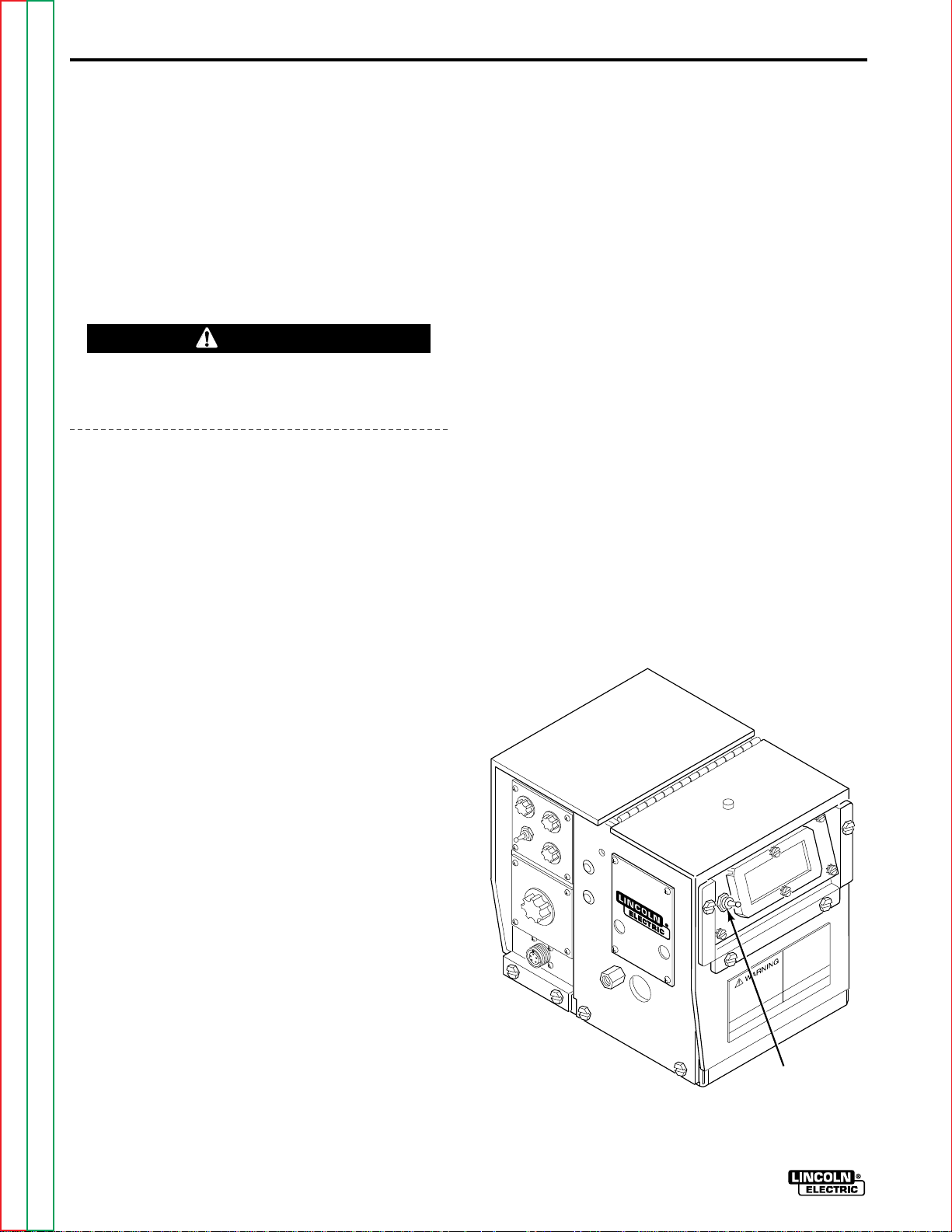
OPERATIONB-14
MAKING A WELD
1. Inch the electrode through the gun and cable. For
solid wire, cut the electrode within approximately
3/8 in. of the end of the contact tip. If using cored
wire, cut the electrode within 3/4 in. of the
extension guide.
2. Connect the work cable to the metal to be welded.
The work cable must make good electrical contact
with the work. The work must also be grounded.
WARNING
When using an open arc process, it is necessary to
use correct eye, head, and body protection.
3. Position the electrode over the joint. The end of
the electrode may be lightly touching the work.
4. Lower your welding helmet. Close the gun trigger
and begin welding. Hold the gun so the contact tip
to work distance gives the correct electrical
stickout as required for the procedure being used.
5. T o stop welding, release the gun trigger and then pull
the gun away from the work after the arc goes out.
OPTIONAL K416 ANALOG AND
K417 DIGITAL VOLTMETER KITS
Lincoln Specified Procedures give voltmeter readings
taken between the work and the gun cable brass
connection block inside the LN-7 GMA. To match these
voltage readings, the #21 lead should be extended
directly to the work per the instructions on the wire
feeder to power source connection diagrams given in
the Installation Section.
To read volts, set the “Electrode Polarity” switch, Figure
B.9, to the same polarity as the electrode lead
connection to the power source.
The K417 Digital Voltmeter Kit has a hold feature that
will freeze the last arc voltage reading at the moment
the trigger is released to stop welding. This feature
allows the welding operator to easily check the arc
voltage and make adjustments if necessary to match
procedures. For accuracy, it is important to release
the gun trigger and the lift the gun away from the
work.
The hold circuit automatically releases about six
seconds after the gun trigger is released. It is also
released when the trigger is closed again to begin
welding.
FIGURE B.9 – ELECTRODE POLARITY SWITCH.
WIRE REEL CHANGING
At the end of a coil, remove the last of the old electrode
from the conductor cable. Either pull it out at the
nozzle, or use the following procedure.
1. Cut off the end of the electrode at the gun end. Do
not break it off by hand. Breaking by hand puts a
slight bend in the wire, making it difficult to pull it
back through the nozzle.
2. Uncouple the gun conductor cable from the
conductor block on the wire feeder drive unit and
lay the gun cable out straight.
3. Using pliers, grip the wire and pull it out of the
cable from the connector end.
4. After the electrode has been removed, connect
the gun conductor back to the wire feeder.
5. Load a new reel of electrode per the instructions
for the specific reel type given previously in this
section.
ELECTRODE
POLARITY
SWITCH
Return to Master TOC Return to Master TOC Return to Master TOC Return to Master TOC
Return to Section TOC Return to Section TOC Return to Section TOC Return to Section TOC
LN-7 GMA WIRE FEEDER
Page 45

OPERATION B-15
FLUX TANK LOADING
K320 FLUX TANK (OPTIONAL)
Either turn off the incoming air line or remove the quick
disconnect if one has been installed. Slightly loosen the
tank cap and let the air in the tank escape in the holes
in the side of the cap. After pressure has been
released, remove the cap from the tank. Using the
funnel provided, put 100 pounds of flux in the tank. It is
very important that only new or properly reclaimed flux
be put in the tank. Coarse particles and/or magnetic
particles will stop the flux feeding process. New Lincoln
flux is properly screened at the factory. All reclaimed
flux must be separately screened through a vibrating
screen with 0.065 in. to 0.075 in. openings and be put
through a magnetic separator. The K310 vibrated
screen and K58 magnetic separator are available for
this purpose. The screen in the funnel supplied with the
tank has much larger openings and its only purpose is
to keep paper and slag out of the tank.
There will always be a small amount of air and possible
drops of water coming out of the end of the tube coiled
under the tank. This is an automatic disposal system in
case the plant air has water and dirt in it.
K310 FLUX SCREEN (OPTIONAL)
The unit was designed to fit the top of either the
standard fill funnel or a K58 magnetic separator. The
unit has a steel screen with 0.065 to 0.075 in. openings
and an air vibrator attached to the frame. The vibrator
can be used with air line pressures ranging from 20
through 100 psi.
For ease of handling, the user should connect the
incoming air line to the 1/8 in. pipe elbow with the aid
of a quick disconnect type air coupling.
It is very important that reclaimed flux to be used in the
continuous flux feeding system be passed through the
K310 screen or its equivalent.
K58 MAGNETIC SEPARATOR (OPTIONAL)
The K58 is a permanent magnet type separator
designed to fit the top of the standard fill funnel of the
continuous flux feeding system.
The purpose of the separator is to remove magnetic
materials such as mill scale and any other extraneous
magnetic materials which may have been recovered
along with the flux to be processed.
It is important to remove these magnetic particles from
the flux which is to be used in the continuous flux
feeding systems. If the magnetic material is not
removed it will gather around the nozzle of the gun and
impede or shut off the flux flow when making relatively
long welds or welding continuously. The magnetic
particles can also cause porosity in the weld.
Return to Master TOC Return to Master TOC Return to Master TOC Return to Master TOC
Return to Section TOC Return to Section TOC Return to Section TOC Return to Section TOC
LN-7 GMA WIRE FEEDER
Page 46

B-16 NOTES
Return to Master TOC Return to Master TOC Return to Master TOC Return to Master TOC
Return to Section TOC Return to Section TOC Return to Section TOC Return to Section TOC
LN-7 GMA WIRE FEEDER
Page 47

TABLE OF CONTENTS
- ACCESSORIES SECTION -
Accessories . . . . . . . . . . . . . . . . . . . . . . . . . . . . . . . . . . . . . . . . . . . . . . . Section C
General . . . . . . . . . . . . . . . . . . . . . . . . . . . . . . . . . . . . . . . . . . . . . . . . C-2
Auxiliary Equipment Connection . . . . . . . . . . . . . . . . . . . . . . . . . . . . . . . C-3
K178-1 Mounting Platform . . . . . . . . . . . . . . . . . . . . . . . . . . . . . . . . . . . C-3
K162H Spindle . . . . . . . . . . . . . . . . . . . . . . . . . . . . . . . . . . . . . . . . . . . . C-3
K163 Undercarriage . . . . . . . . . . . . . . . . . . . . . . . . . . . . . . . . . . . . . . . . C-3
K419 Burnback Timer Kit . . . . . . . . . . . . . . . . . . . . . . . . . . . . . . . . . . . . C-3
K418 GMA Timer Kit . . . . . . . . . . . . . . . . . . . . . . . . . . . . . . . . . . . . . . . C-4
K416 Analog Voltmeter Kit . . . . . . . . . . . . . . . . . . . . . . . . . . . . . . . . . . . C-4
K417 Digital Voltmeter Kit . . . . . . . . . . . . . . . . . . . . . . . . . . . . . . . . . . . C-4
K775 or K857 Remote Voltage Control Kit . . . . . . . . . . . . . . . . . . . . . . . C-4
K320 Flux Tank . . . . . . . . . . . . . . . . . . . . . . . . . . . . . . . . . . . . . . . . . . . C-4
Wire Reel Dust Shield for K376 50 to 60 Lb Wire Reel
Mounting Stand . . . . . . . . . . . . . . . . . . . . . . . . . . . . . . . . . . . . . . . . . C-5
Wire Reel Dust Shield Door for K303 and K376 . . . . . . . . . . . . . . . . . . . C-5
K377 Small Mounting Stand for Readi-Reel Coils
or 10 to 30 lb Spools with 2 in. I.D. . . . . . . . . . . . . . . . . . . . . . . . . . . C-5
K378 Small Mounting Stand for 13 to 14 Lb Innershield Coils . . . . . . . . . C-5
K292 Power Input Extension Cable (600 Amps) . . . . . . . . . . . . . . . . . . . C-5
Power Input Cables . . . . . . . . . . . . . . . . . . . . . . . . . . . . . . . . . . . . . . . . C-5
K291 Input Cable . . . . . . . . . . . . . . . . . . . . . . . . . . . . . . . . . . . . . . . C-5
K404 Input Cable . . . . . . . . . . . . . . . . . . . . . . . . . . . . . . . . . . . . . . . C-5
K480 Input Cable . . . . . . . . . . . . . . . . . . . . . . . . . . . . . . . . . . . . . . . C-6
K584 and K594 Input Cables . . . . . . . . . . . . . . . . . . . . . . . . . . . . . . . C-6
Welding Guns . . . . . . . . . . . . . . . . . . . . . . . . . . . . . . . . . . . . . . . . . . . . C-6
Innershield Guns . . . . . . . . . . . . . . . . . . . . . . . . . . . . . . . . . . . . . . . . C-6
Submerged Arc Guns . . . . . . . . . . . . . . . . . . . . . . . . . . . . . . . . . . . . C-7
GMAW Guns . . . . . . . . . . . . . . . . . . . . . . . . . . . . . . . . . . . . . . . . . . . C-7
K527 Water Solenoid Kit . . . . . . . . . . . . . . . . . . . . . . . . . . . . . . . . . . . . C-7
K376 and K303 50-60 lb Wire Reel Mounting Stands . . . . . . . . . . . . . . . C-7
Attaching the Wire Reel Stand . . . . . . . . . . . . . . . . . . . . . . . . . . . . . . . . C-7
Section C
Return to Master TOC Return to Master TOC Return to Master TOC Return to Master TOC
LN-7 GMA WIRE FEEDER
Page 48

C-2 ACCESSORIES
GENERAL
The following is a list of the accessories that
can be used with the LN-7 GMA wire feeder.
TABLE C.1 – LN-7 GMA ACCESSORIES.
Product Number Name
K178-1 Mounting platform
K162H High capacity spindle
K163 Undercarriage
K419 Burnback timer kit
K418 GMA Timer Kit
K416 Analog voltmeter kit
K417 Digital voltmeter kit
K775/K857 Remote voltage control kit
K320 Flux tank
K376/K303 50-60 lb Wire reel mounting stand
S-14543 Wire reel dust shield for K376
A detailed description of each item is given
later in this section.
M-11514 Wire reel dust shield door for K303/K376
K377 Mounting stand for Readi-Reels and 10-30 lb spools
K378 Mounting stand for 13-14 lb Innershield coils
K292 Power input extension cables
K291 Power input cable - 600 Amps
K404 Power input cable - 350 Amps
K480 Power input cable - 400 Amps
K126 Innershield welding gun - 350 Amps
K115 Innershield welding gun - 450 Amps
K112 Submerged arc welding gun - 500 Amps
K113 Submerged arc welding gun - 600 Amps
K497 Magnum GMA welding gun - 200 Amps*
K470 Magnum GMA welding gun - 300 Amps*
K471 Magnum GMA welding gun - 400 Amps*
K527 Water solenoid kit
*
Magnum GMA welding guns require a K466-1 connector for use with the LN-7 GMA wire
feeder.
Return to Master TOC Return to Master TOC Return to Master TOC Return to Master TOC
Return to Section TOC Return to Section TOC Return to Section TOC Return to Section TOC
LN-7 GMA WIRE FEEDER
Page 49

ACCESSORIES C-3
AUXILIARY EQUIPMENT
CONNECTION
The LN-7 GMA has the factory installed gas
solenoid valve leads attached to terminals 7
and 32A. Additional auxiliary equipment
connection is not recommended. If the gas
solenoid is NOT connected to terminals 7
and 32A, other auxiliary equipment may be
connected but the current draw must NOT
exceed 1/4 ampere.
CAUTION
Do not connect the power source contactor
to these terminals.
NOTE: The auxiliary equipment contacts
open when the trigger is released. When the
optional K418 GMATimer Kit is installed, the
auxiliary contacts open after the postflow
time delay.
WARNING
Do not use coils or spools heavier than
30 lbs on the original K162 spindle.
To mount the 2 in. spindle kit for Readi-Reels
and 10 through 60 lb spools, remove the
shaft for the standard 50-60 pound wire coils
from the mounting framework. Install the
spindle per the instructions (M15241)
shipped with the spindle kit.
K163 UNDERCARRIAGE
The undercarriage includes casters, wheels,
a handle, and related hardware. Casters are
mounted at the front and wheels at the rear
of the platform. The handle is bolted to the
front of the platform so the wire feeder can
be tilted back and wheeled like a two-wheel
truck. Installation sheet M13424 is provided
with the undercarriage.
K178-1 MOUNTING
PLATFORM
This is a turntable type platform for mounting
the LN-7 GMA to the top of Idealarc power
sources. Bolt the platform to the lift bail per
the instructions (M16260) supplied with the
platform.
K162H SPINDLE
The K162H spindle is used for mounting
Readi-Reels and 2 in. I.D. spools with a 60 lb
capacity on a K303 or K376 Wire Reel
Stand. When used with Read-Reels, a ReadReel Adapter is required. For 8 in. O.D.
spools, a K468 Spindle Adapter is available.
The K162H is a high capacity design which
replaces the original K162 30 lb spindle. The
K162H spindle has a white spacer and has
part no. M-14587-1 molded on. The original
K162 spindle has a black spacer and the part
no. M14587. Parts may not be exchanged
from one design to the other.
K419 BURNBACK TIMER KIT
The kit is available for those applications
where the LN-7 GMA is used for higher
speed, fine wire feeding (0.023 in. to 0.045
in. wire sizes) where there is a tendency for
the electrode to overrun at the end of the
weld causing “sticking” in the crater. The kit
provides a precise time delay that allows the
wire to be burned off at the end of the weld.
The delay is adjustable for optimum
burnback depending on wire size, process,
procedure, etc. This kit also includes a cold
inch switch.
The K419 Burnback Kit is also useful for
those installations where the gun is clamped
in a fixture and cannot be lifted from the work
at the end of the weld.
Installation and operation instructions
(M15060) are included with the kit.
Return to Master TOC Return to Master TOC Return to Master TOC Return to Master TOC
Return to Section TOC Return to Section TOC Return to Section TOC Return to Section TOC
LN-7 GMA WIRE FEEDER
Page 50

ACCESSORIESC-4
K418 GMA TIMER KIT
This kit is available to provide the following
functions:
1. Preflow Control – Provides flow of
shielding gas to the work before the arc
is established. The solenoid valve is
energized immediately when the gun
trigger is closed, but the time delay
before the wire feeder is energized is
adjustable to between 0 and 1.5
seconds.
2. Postflow Control – Provides flow of
shielding gas to the work after welding
is stopped. Solenoid valve shutoff delay
after the trigger is released is
adjustable from 0.5 to 4.5 seconds.
3. Burnback Control – Provides a precise
time delay that allows the wire to be
burned off at the end of the weld. The
delay is adjustable for optimum
burnback depending on the wire size,
process, procedure, etc.
4. Purge - Cold Inch Switch – Momentary
Up position energizes the gas solenoid
but not the wire feeder or welding
power source. Momentary down
position energizes the wire feeder but
not the welding power source or the gas
solenoid valve.
Installation and operation instructions
(M15059) are included with the kit.
that freezes the display for approximately six
seconds at the reading just prior to stopping
welding. This feature allows the operator to
easily check his procedure at the end of the
weld and make adjustments if required.
Installation instructions (M15080) are
included with the kit.
K775 OR K857 REMOTE
VOLTAGE CONTROL KIT
Either control installs on the side of the LN-7
GMA control box cover and gives voltage
control at the wire feeder.
K775 can be installed on the LN-7 GMA
when it is used with R3S, DC-250, DC-400,
CV-400, OR DC-600 power sources. A
control cable from the K775 attaches to the
power source terminal strip. See the
instructions (S14267) included with the kit.
K857 can be installed on the LN-7 GMA
when it is used with newer Lincoln power
sources such as the CV-300 with K856
remote kit installed. These power sources
are equipped with a 6-socket ms-type
receptacle for connection of the plug on the
28 ft (8.5 m) control cable of the K857. See
the instructions (S19103) included with the
kit.
A remote output is also available for use with
SAM power sources. See the SAM
Operating Manual.
Return to Master TOC Return to Master TOC Return to Master TOC Return to Master TOC
Return to Section TOC Return to Section TOC Return to Section TOC Return to Section TOC
LN-7 GMA WIRE FEEDER
K416 ANALOG VOLTMETER
KIT
Includes a 0 to 60 volt DC analog meter and
a polarity switch. It mounts in the hinged wire
drive section cover. Installation instructions
(M15080) are included with the kit.
K417 DIGITAL VOLTMETER
KIT
Includes a three digit LED display and a
polarity switch. Also includes a hold feature
K320 FLUX TANK
The K320 flux tank is available to permit the
LN-7 GMA to be used for submerged arc
welding.
Install per the instructions shipped with the
kit.
Page 51

ACCESSORIES C-5
WIRE REEL DUST SHIELD
FOR K376 50 TO 60 LB WIRE
REEL MOUNTING STAND
A shield is available to cover the wire and
reel to protect the wire from falling dirt and
dust. Order part no. S-14543. Instructions
are provided with the kit.
WIRE REEL DUST SHIELD
DOOR FOR K303 AND K376
In extremely dusty and dirty locations this
door kit can be added to those units having
the dust shield kit (S-14543). This door kit
includes a hinged door and sliding bottom
seal. When these parts are attached to the
reel support per the instructions included, the
unit becomes a completely enclosed
housing. Order part no. M11514.
K377 SMALL MOUNTING
STAND FOR READ-REEL
COILS OR 10 TO 30 LB
SPOOLS WITH 2 IN. I.D.
enclosed canister system for dereeling of the
14 lb coil. This system has a fixed brake for
the 14 lb coil. See Attaching the Wire Reel
Stand Procedure at the end of this section
for installation procedures.
K292 POWER INPUT
EXTENSION CABLE
(600 AMPS)
Can be used to a maximum of 400 ft (122 m).
See Input Cable Connections section in the
Installation Section for a description of this
cable.
POWER INPUT CABLES
A variety of power input cable assemblies
are available for various current ratings and
power source connection types. All provide a
polarized control cable plug (MS-3106A-1812S) and a lugged electrode cable for connection to the wire feeder.
K291 INPUT CABLE
This assembly includes a wire reel spindle
(similar to the K162 spindle) attached to a
small frame. The unit is supplied with the
K363 Readi-Reel Adapter for using the
Lincoln “Readi-Reel Electrode Coils”.
Without the adapter the unit is capable of
handling spools with a 2 in. I.D., a 12 in.
maximum O.D., and a 4 in. width. For spools
with an 8 in. O.D., a K468 spindle adapter is
available. The spindle has an adjustable
braking system. See Attaching the Wire Reel
Stand procedure at the end of this section for
installation procedures.
K378 SMALL MOUNTING
STAND FOR 13 TO 14 LB
INNERSHIELD COILS
This assembly includes the same smaller
frame as used in the K377 and the fully
The K291 input cable assembly consists of
a six-conductor control cable and a 3/0
(85 mm2) electrode cable. It is rated at 600
amps, 60% duty cycle and is available in
lengths of 10, 25, 50, 75, and 100 feet (3.0,
7.6, 15.2, 22.9, and 30.4 m).
K404 INPUT CABLE
The K404 input cable is similar to the K291
but includes a 1/0 (53 mm2) electrode cable.
It is rated at 350 amps, 60% duty cycle. It is
available in lengths of 10, 25, and 50 feet
(3.0, 7.6, and 15.2 m). These control cables
have lugged leads for power sources with
stud output terminals and terminal strip
control lead connections.
Return to Master TOC Return to Master TOC Return to Master TOC Return to Master TOC
Return to Section TOC Return to Section TOC Return to Section TOC Return to Section TOC
LN-7 GMA WIRE FEEDER
Page 52

ACCESSORIESC-6
K480 INPUT CABLE
The K480 input cable includes a 2/0
(67 mm2) weld cable with a Twist-Mate
connector and a 14-pin (MS-3106A-2027PX) plug to be compatible with the smaller
Lincoln power sources (such as the CV-300).
The K480 is rated at 400 amps, 60% duty
cycle and is available in 10, 25, and 50 foot
(3.0, 7.6, and 15.2 m) lengths.
TM
K584 AND K594 INPUT CABLES
The K584 input cable includes a 1/0
(53 mm2) electrode cable rated at 350 amps,
60% duty cycle, and the K594 input cable
includes a 3/0 (85 mm2) electrode cable
rated at 600 amps, 60% duty cycle. Both are
for power sources with stud output terminals
and a 14-pin control receptacle, and are
available in 10, 25, and 50 foot (3.0, 7.6, and
15.2 m) lengths.
WELDING GUNS
For heavy duty welding at up to 450 amps
and with 0.068 in. through 3/32 in.
Innershield electrode, use an appropriate
K115 or K115-45 gun and cable assembly
(See Figure C.2). Install the proper insulated
nozzle extension and contact tip for the
stickout and electrode size being used.
For welding with 7/64 in. Innershield
electrode, use a K115-3/32 with an M11474120 nozzle or a K115-45-3/32 with an
M11510-120 nozzle. Also install a 7/64 in.
contact tip and install the insulated nozzle
extension for the stickout being used.
NOTE: Linconditioner
recommended for locations where smoke
accumulation is a problem and conventional
exhaust systems are ineffective. The
available smoke removal type Innershield
guns and vacuum units can be used in these
locations. Instructions are shipped with the
equipment.
FIGURE C.2 – THE K115 AND
K115-45 GUNS.
TM
guns are
INNERSHIELD GUNS
The K126 gun and cable assembly is
recommended for most welding with 0.062
in. through 3/32 in. Innershield electrodes at
up to 350 amps. Install the insulated nozzle
extension (or thread protector) and the
nozzle contact tip for the stickout and
electrode size being used. (See Figure C.1.)
FIGURE C.1 – THE K126 GUN.
Return to Master TOC Return to Master TOC Return to Master TOC Return to Master TOC
Return to Section TOC Return to Section TOC Return to Section TOC Return to Section TOC
LN-7 GMA WIRE FEEDER
Page 53

ACCESSORIES C-7
SUBMERGED ARC GUNS
The K112 gun and cable assembly is
recommended for welding with 1/16 in. solid
steel electrode at up to 500 amps. The K113
gun and cable is recommended for 5/64 in.
and 3/32 in. (2.0 and 2.4 mm) solid steel
electrodes (types L50, L60, L61, and L70) for
use up to 600 amps.
GMAW GUNS
An expanding line of Magnum GMA gun and
cable assemblies are available to allow
welding with solid and cored electrodes
using the GMAW process. See the
appropriate Magnum literature for
descriptions of the 100-500 ampere air
cooled gun and cables that are available.
Gun cable lengths range from 10 to 25 ft.
(3.0 to 7.5 m) and feed electrode sizes
0.023 in. to 3/32 in. (0.6 to 2.4 mm).
NOTE: Magnum GMA welding guns require
a K466-1 connector for use with an LN-7
GMA wire feeder.
K376 AND K303 50 TO 60 LB
WIRE REEL MOUNTING
STANDS
The K376 50 to 60 lb Wire Reel Mounting
Stand and the K303 Wire Reel Mounting
Stand are the same with the exception that
the K303 stand includes a dust shield. The
assembly includes a framework to which is
attached the 50 to 60 lb wire reel, a mounting
spindle, a lift bale, and a cable clamp for
fastening the input cable assembly. It is
easily mounted to the basic wire feed unit by
following the Attaching the Wire Reel Stand
procedure at the end of this section.
ATTACHING THE WIRE REEL
STAND
The mounting hardware for mounting the
stands is included with the LN-7 GMA.
Screws and washers are inserted in their
respective mounting holes. To connect:
1. Remove the three 3/8 in. hex head bolts
from the back of the wire feed unit.
K527 WATER SOLENOID KIT
Install and connect per the instructions
(M16261) shipped with the kit.
This kit is factory installed on the K440-1
LN-7 GMA.
2. Place the wire reel mounting stand
mounting bracket in position against the
back of the wire feed unit.
3. Replace and tighten the hex head bolts.
The long screw and plain washer go
into the top hole.
Return to Master TOC Return to Master TOC Return to Master TOC Return to Master TOC
Return to Section TOC Return to Section TOC Return to Section TOC Return to Section TOC
LN-7 GMA WIRE FEEDER
Page 54

NOTESC-8
Return to Master TOC Return to Master TOC Return to Master TOC Return to Master TOC
Return to Section TOC Return to Section TOC Return to Section TOC Return to Section TOC
LN-7 GMA WIRE FEEDER
Page 55

TABLE OF CONTENTS
- MAINTENANCE SECTION -
Maintenance . . . . . . . . . . . . . . . . . . . . . . . . . . . . . . . . . . . . . . . . . . . . . . . Section D
Routine Maintenance . . . . . . . . . . . . . . . . . . . . . . . . . . . . . . . . . . . . . . D-2
Drive Rolls and Guide Tubes . . . . . . . . . . . . . . . . . . . . . . . . . . . . . D-2
Wire Reel Mounting . . . . . . . . . . . . . . . . . . . . . . . . . . . . . . . . . . . . D-2
Periodic Maintenance . . . . . . . . . . . . . . . . . . . . . . . . . . . . . . . . . . . . . . D-2
Wire Drive Motor and Gearbox . . . . . . . . . . . . . . . . . . . . . . . . . . . . D-2
Gun and Cable Maintenance . . . . . . . . . . . . . . . . . . . . . . . . . . . . . D-2
Section D
Return to Master TOC Return to Master TOC Return to Master TOC Return to Master TOC
LN-7 GMA WIRE FEEDER
Page 56

D-2 MAINTENANCE
ROUTINE MAINTENANCE
DRIVE ROLLS AND GUIDE TUBES
After feeding every coil of wire, inspect the
drive roll section. Clean the assembly as
necessary. Do not use solvent to clean the
drive roll assembly as it may wash the
lubricant out of the bearings. The drive rolls
and guide tubes are stamped with the wire
sizes they will feed. If a wire size other than
that stamped on the rolls is to be used, the
rolls and guide tubes must be changed.
The drive rolls for 0.045 and 0.052 cored
electrode and 1/16, 0.068, 5/64, 3/32, and
7/64 electrode have a double set of teeth so
they can be reversed for additional life.
Between the two knurled rolls (except 1/16
and smaller rolls) is a shim washer which
limits the damage to the electrode if wire
feeding problems occur. Drive rolls for 0.023
through 0.052 solid electrodes have no
teeth.
layer of grease. No maintenance to the two
position brake is required. If the brake shoe
wears through to metal, replace the brake
assembly.
No routine maintenance is required for
Readi-Reels and 10 to 30 lb spools. Do not
lubricate the 2 in. spindles.
PERIODIC MAINTENANCE
WIRE DRIVE MOTOR AND
GEARBOX
Every year inspect the gearbox and coat the
gear teeth with a moly-disulfide filled grease.
Do not use graphite grease.
Every six months check the motor brushes.
Replace them if they are less than 1/4 in.
long.
GUN AND CABLE MAINTENANCE
Refer to the instructions included with the
drive roll kit for installation and replacement
of the drive rolls on the wire feeder.
WIRE REEL MOUNTING
To prolong the life of the reel shaft on the 50
to 60 lb coils, periodically coat it with a thin
For instructions on periodic maintenance for
the welding gun and cables, refer to the
manual for your specific model of welding
gun.
Return to Master TOC Return to Master TOC Return to Master TOC Return to Master TOC
Return to Section TOC Return to Section TOC Return to Section TOC Return to Section TOC
LN-7 GMA WIRE FEEDER
Page 57

TABLE OF CONTENTS
- THEORY OF OPERATION SECTION -
Theory of Operation . . . . . . . . . . . . . . . . . . . . . . . . . . . . . . . . . . . . . . . . . Section E
General . . . . . . . . . . . . . . . . . . . . . . . . . . . . . . . . . . . . . . . . . . . . . . . . E-2
Control Circuit Operation . . . . . . . . . . . . . . . . . . . . . . . . . . . . . . . . . . . E-2
Power Input Circuits . . . . . . . . . . . . . . . . . . . . . . . . . . . . . . . . . . . . E-2
Trigger Circuit . . . . . . . . . . . . . . . . . . . . . . . . . . . . . . . . . . . . . . . . E-3
Control Relay Circuit . . . . . . . . . . . . . . . . . . . . . . . . . . . . . . . . . . . E-4
Auxiliary Circuits . . . . . . . . . . . . . . . . . . . . . . . . . . . . . . . . . . . . . . E-5
Protective Circuits . . . . . . . . . . . . . . . . . . . . . . . . . . . . . . . . . . . . . . . . E-6
Overload Protection . . . . . . . . . . . . . . . . . . . . . . . . . . . . . . . . . . . . E-6
Current Limiting Circuit . . . . . . . . . . . . . . . . . . . . . . . . . . . . . . . . . . E-6
Ground Lead Protection . . . . . . . . . . . . . . . . . . . . . . . . . . . . . . . . . E-7
SCR Operation . . . . . . . . . . . . . . . . . . . . . . . . . . . . . . . . . . . . . . . . . . . E-7
Section E
Return to Master TOC Return to Master TOC Return to Master TOC Return to Master TOC
LN-7 GMA WIRE FEEDER
Page 58

E-2
THEORY OF OPERATION
FROM
WELDING
POWER
SUPPLY
CIRCUIT
BREAKER
115 VAC
GENERAL
feeder. The operation of the two versions is
virtually identical. The following description
The LN-7 GMAwire feeder is available in two
versions, a two-roll and a four-roll wire
of the operation of the wire feeders applies
equally to both versions of the LN-7 GMA.
FIGURE E.1 – INPUT LINE VOLTAGE AND TRIGGER TRANSFORMER.
OPTIONAL
TIMER OR
BURNBACK KIT
CURRENT
LIMITING
CIRCUIT
CONTROL
BOARD
5-95 VDC
WIRE DRIVE
TRIGGER
TRANS-
FORMER
8.8 VAC
24 VAC
OPTIONAL
METER KIT
DIODE
RECTIFIER
NETWORK
115 VAC
24 VDC
GAS
SOLENOID
SCR
POWER
CIRCUIT
115 VAC
CONTROL
RELAY
CR1
MOTOR
TO WELDING
CONTACTOR
WIRE
SPEED
CONTROL
GROUND
LEAD
PROTECTOR
CONTROL CIRCUIT
OPERATION
POWER INPUT CIRCUITS
The LN-7 GMA receives 115 VAC power
from the welding supply. This power is
GUN
TRIGGER
applied to the trigger transformer which
reduces the voltage for use by the LN-7
electronics. The voltages produced are 24
VAC, used by the electronics and the trigger
circuit, and 8.8, VAC used by the optional
digital meter kit. The 115 VAC input power is
also sent to the SCR circuitry which powers
the wire feed motor. See Figure E.1.
Return to Master TOC Return to Master TOC Return to Master TOC Return to Master TOC
Return to Section TOC Return to Section TOC Return to Section TOC Return to Section TOC
LN-7 GMA WIRE FEEDER
NOTE: Unshaded areas of block logic diagrams are the subject of discussion.
Page 59

THEORY OF OPERATION E-3
FIGURE E.2 – TRIGGER CIRCUIT.
FROM
WELDING
POWER
SUPPLY
CIRCUIT
BREAKER
115 VAC
TRIGGER
TRANS-
FORMER
8.8 VAC
24 VAC
OPTIONAL
METER KIT
DIODE
RECTIFIER
NETWORK
WIRE
SPEED
CONTROL
115 VAC
24 VDC
GAS
SOLENOID
SCR
POWER
CIRCUIT
CONTROL
RELAY
GROUND
PROTECTOR
115 VAC
CR1
LEAD
OPTIONAL
TIMER OR
BURNBACK KIT
CURRENT
LIMITING
CIRCUIT
CONTROL
BOARD
5-95 VDC
WIRE DRIVE
MOTOR
GUN
TRIGGER
TO WELDING
CONTACTOR
Return to Master TOC Return to Master TOC Return to Master TOC Return to Master TOC
Return to Section TOC Return to Section TOC Return to Section TOC Return to Section TOC
TRIGGER CIRCUIT
pulled, a circuit is closed which energizes the
control relay. The three sets of contacts in
The 24 VAC output of the trigger transformer
is sent to the control PC board and rectified
the relay close and energize the multiple
functions of the wire feeder. See Figure E.2.
by a diode network. When the gun trigger is
NOTE: Unshaded areas of block logic diagrams are the subject of discussion.
LN-7 GMA WIRE FEEDER
Page 60

E-4 THEORY OF OPERATION
FIGURE E.3 – CONTROL CIRCUITS.
FROM
WELDING
POWER
SUPPLY
CIRCUIT
BREAKER
115 VAC
TRIGGER
TRANS-
FORMER
8.8 VAC
24 VAC
OPTIONAL
METER KIT
DIODE
RECTIFIER
NETWORK
WIRE
SPEED
CONTROL
115 VAC
24 VDC
GAS
SOLENOID
SCR
POWER
CIRCUIT
CONTROL
RELAY
GROUND
PROTECTOR
115 VAC
CR1
LEAD
OPTIONAL
TIMER OR
BURNBACK KIT
CURRENT
LIMITING
CIRCUIT
CONTROL
BOARD
5-95 VDC
WIRE DRIVE
MOTOR
GUN
TRIGGER
TO WELDING
CONTACTOR
Return to Master TOC Return to Master TOC Return to Master TOC Return to Master TOC
Return to Section TOC Return to Section TOC Return to Section TOC Return to Section TOC
LN-7 GMA WIRE FEEDER
CONTROL RELAY CIRCUIT
wire speed control. The faster the speed
setting, the higher the voltage that is applied
The first contact closes to allow 115 VAC to
energize the gas solenoid. This allows
shielding gas to flow to the gun. The second
contact of the control relay closes the circuit
in the welding power source contactor circuit.
to the wire drive motor. The gearbox
transfers the power of the rotating motor to
the drive roll. On a four-roll wire feeder, the
gearbox also splits the drive power to two
separate drive rolls.
This signals the welding power source to
provide power to the gun. The last set of
contacts on the control relay disables the
motor dynamic braking circuit and closes the
motor power supply circuit. See Figure E.3.
When the trigger is released, the control
relay is de-energized. This opens the
contacts which de-energize the gas
solenoid, open the welding power source
contactor circuit, and stop the wire drive
When the control relay closes the motor
contacts, the SCR power circuit supplies a
DC voltage to the wire drive motor. This
motor. The dynamic braking circuit engages
to rapidly stop the wire drive motor and
prevent wire overrun.
voltage is dependent on the setting of the
NOTE: Unshaded areas of block logic diagrams are the subject of discussion.
Page 61

THEORY OF OPERATION E-5
FIGURE E.4 – AUXILIARY CIRCUITS.
FROM
WELDING
POWER
SUPPLY
CIRCUIT
BREAKER
115 VAC
TRIGGER
TRANS-
FORMER
8.8 VAC
24 VAC
OPTIONAL
METER KIT
DIODE
RECTIFIER
NETWORK
WIRE
SPEED
CONTROL
115 VAC
24 VDC
GAS
SOLENOID
SCR
POWER
CIRCUIT
CONTROL
RELAY
GROUND
PROTECTOR
115 VAC
CR1
LEAD
OPTIONAL
TIMER OR
BURNBACK KIT
CURRENT
LIMITING
CIRCUIT
CONTROL
BOARD
5-95 VDC
WIRE DRIVE
MOTOR
GUN
TRIGGER
TO WELDING
CONTACTOR
Return to Master TOC Return to Master TOC Return to Master TOC Return to Master TOC
Return to Section TOC Return to Section TOC Return to Section TOC Return to Section TOC
AUXILIARY CIRCUITS
TIMER KITS
METER KITS
The optional meter kit indicates the welding
voltage from the electrode to the work. This
The optional GMA Timer and Burnback kits
can be added to provide time delays for
these functions. Both kits provide a burnback
control which maintains the welding power
source contacts closed for a short time after
the trigger is released. The timer kit also has
voltage is measured from the contact block in
the wire drive compartment to the work.
While the analog meter kit does not require
any additional power, the digital meter kit is
powered by an 8.8 VAC signal from the
trigger transformer. See Figure E.4.
controls which can provide a gas preflow and
postflow by controlling the timing of the gas
solenoid. See Figure E.4.
NOTE: Unshaded areas of block logic diagrams are the subject of discussion.
LN-7 GMA WIRE FEEDER
Page 62

E-6 THEORY OF OPERATION
FIGURE E.5 – PROTECTIVE CIRCUITS.
FROM
WELDING
POWER
SUPPLY
CIRCUIT
BREAKER
115 VAC
TRIGGER
TRANS-
FORMER
8.8 VAC
24 VAC
OPTIONAL
METER KIT
DIODE
RECTIFIER
NETWORK
WIRE
SPEED
CONTROL
115 VAC
24 VDC
GAS
SOLENOID
SCR
POWER
CIRCUIT
CONTROL
RELAY
GROUND
PROTECTOR
115 VAC
CR1
LEAD
OPTIONAL
TIMER OR
BURNBACK KIT
CURRENT
LIMITING
CIRCUIT
CONTROL
BOARD
5-95 VDC
WIRE DRIVE
MOTOR
GUN
TRIGGER
TO WELDING
CONTACTOR
Return to Master TOC Return to Master TOC Return to Master TOC Return to Master TOC
Return to Section TOC Return to Section TOC Return to Section TOC Return to Section TOC
PROTECTIVE CIRCUITS
Protective circuits are designed in to the
LN-7 GMA to detect trouble and shut down
the wire feeder before any damage to the
feeder can result. The wire feeder contains
overload protection for the entire machine, a
current limiting circuit for the feed motor, and
a ground lead protection circuit.
CURRENT LIMITING CIRCUIT
The current limiting circuit limits the current
that is sent to the feed motor. A precision
resistor in line with the feed motor produces
a voltage drop that is directly proportional to
the current draw of the motor. If the signal
exceeds 10VDC, which equates to a 10A
draw from the feed motor, the current limiter
sends a signal to the SCR power circuit to
OVERLOAD PROTECTION
limit feed motor current to 10A. Refer to
Figure E.5.
The wire feeder is equipped with a circuit
breaker in the 115 Vac input power circuit to
protect the feeder in the event of an electrical
fault. Refer to Figure E.5. If the feeder draws
more than 2.5A, the circuit breaker will trip to
prevent any damage to the wire feeder.
NOTE: Unshaded areas of block logic diagrams are the subject of discussion.
LN-7 GMA WIRE FEEDER
Page 63

THEORY OF OPERATION E-7
GROUND LEAD PROTECTION
The Ground Lead Protector (GLP) circuit
protects the ground lead that connects the
wire feeder to the welding power source.
When the circuit detects any current flow in
the ground lead, a contact closes in the
control circuit which de-energizes the control
relay. Refer to Figure E.5. This opens the
circuit for the welding relay in the welding
power supply to remove power from the
welding gun, shuts the gas and water
solenoids, and stops the wire feed motor.
The GLP circuit remains in this tripped state
until the reset button on the wire feeder is
pressed, or power is removed from the wire
feeder.
SCR OPERATION
Since the wire speed of the LN-7GMA is
controlled by SCR circuitry, a basic
understanding of how an SCR functions is
important. Refer to Figure E.6 and the
following explanation. A silicon controlled
rectifier (SCR) is a three terminal semiconductor device used to control currents to
a load. An SCR acts very much like a switch.
When a gate signal is applied to the SCR it
is turned on and there is current flow from
anode to cathode. In the on state the SCR
acts like a closed switch. When the SCR is
turned off there is no current flow, thus the
device acts like an open switch. As the name
suggests, the SCR is a rectifier, so it passes
current only during positive half cycles of the
AC supply, The positive half cycle is the
portion of the sine wave in which the anode
of the SCR is more positive than the
cathode.
When an AC supply voltage is applied to the
SCR, the device spends a certain portion of
the AC cycle time in the on state and the
remainder of the time in the off state. The
amount of time spent in the on state is
controlled by the gate.
An SCR is fired by a short burst of current
into the gate. This gate pulse must be more
positive than the cathode voltage. Since
there is a standard pn junction between the
gate and cathode, the voltage between
these terminals must be slightly greater than
0.6 VDC. Once the SCR has fired it is not
necessary to continue the flow of gate
current. As long as current continues to flow
from anode to cathode the SCR will remain
on. When the anode to cathode current
drops below a minimum value, called holding
current, the SCR will shut off. This normally
occurs as the AC supply voltage passes
through zero into the negative portion of the
sine wave. If the SCR is turned on early in
the positive half cycle, the conduction time is
longer, resulting in greater SCR output. If the
gate firing time is later in the cycle the
conduction time is less, resulting in lower
SCR output.
ANODE
Return to Master TOC Return to Master TOC Return to Master TOC Return to Master TOC
Return to Section TOC Return to Section TOC Return to Section TOC Return to Section TOC
FIGURE E.6 – SILICON-CONTROLLED RECTIFIER OPERATION.
INPUT
CATHODE
OUTPUT
GATE
GATE
NOTE:
AS THE GATE
PULSE IS APPLIED
LATER IN THE
CYCLE THE SCR
OUTPUT IS
DECREASED.
LN-7 GMA WIRE FEEDER
Page 64

E-8
NOTES
Return to Master TOC Return to Master TOC Return to Master TOC Return to Master TOC
Return to Section TOC Return to Section TOC Return to Section TOC Return to Section TOC
LN-7 GMA WIRE FEEDER
Page 65

TABLE OF CONTENTS
- TROUBLESHOOTING AND REPAIR SECTION -
Troubleshooting And Repair . . . . . . . . . . . . . . . . . . . . . . . . . . . . . . . . . . Section F
How To Use Troubleshooting Guide . . . . . . . . . . . . . . . . . . . . . . . . . . . F-2
PC Board Troubleshooting Procedures . . . . . . . . . . . . . . . . . . . . . . . . . F-3
Troubleshooting Guide . . . . . . . . . . . . . . . . . . . . . . . . . . . . . . . . . . . . . F-4
Test Procedures . . . . . . . . . . . . . . . . . . . . . . . . . . . . . . . . . . . . . . . . . . F-12
Control Relay Test . . . . . . . . . . . . . . . . . . . . . . . . . . . . . . . . . . . . . F-12
Trigger Transformer Test . . . . . . . . . . . . . . . . . . . . . . . . . . . . . . . . F-14
Control Cable Continuity Test . . . . . . . . . . . . . . . . . . . . . . . . . . . . . F-16
Component Replacement Procedures . . . . . . . . . . . . . . . . . . . . . . . . . F-18
Wire Feed Speed Potentiometer Replacement . . . . . . . . . . . . . . . F-18
Circuit Breaker Replacement . . . . . . . . . . . . . . . . . . . . . . . . . . . . . F-21
Ground Lead Protector Push Button Switch Replacement . . . . . . . F-23
Trigger Transformer Replacement . . . . . . . . . . . . . . . . . . . . . . . . . F-25
Ground Lead Protector Reed Switch Replacement . . . . . . . . . . . . . F-27
Control PC Board Replacement . . . . . . . . . . . . . . . . . . . . . . . . . . . F-29
Main Power Resistor (R1) Replacement . . . . . . . . . . . . . . . . . . . . . F-32
Control Relay Replacement . . . . . . . . . . . . . . . . . . . . . . . . . . . . . . F-35
Wire Drive Assembly and Components Replacement . . . . . . . . . . . F-37
Swing Arm Assembly Replacement for Two-Roll Wire Feeders . . . . F-41
Swing Arm Assembly Replacement for Four-Roll Wire Feeders . . . F-44
Gas Solenoid and Connections Replacement . . . . . . . . . . . . . . . . . F-47
Retest After Repair . . . . . . . . . . . . . . . . . . . . . . . . . . . . . . . . . . . . . . . . F-50
Section F
WARNING
ELECTRIC SHOCK can kill.
• Never work on the inside of the machine without turning off the input
power. You can receive a life threatening electrical shock if you fail to
do this. Only qualified technicians should perform installation,
maintenance, and troubleshooting work on the machine.
Return to Master TOC Return to Master TOC Return to Master TOC Return to Master TOC
LN-7 GMA WIRE FEEDER
Page 66

F-2
TROUBLESHOOTING AND REPAIR
How To Use Troubleshooting Guide
Service and Repair should only be performed by Lincoln Electric Factory Trained
Personnel. Unauthorized repairs performed on this equipment may result in danger to the
technician and machine operator and will invalidate your factory warranty. For your
safety and to avoid Electrical Shock, please observe all safety notes and precautions
detailed throughout this manual.
WARNING
This Troubleshooting Guide is provided to
help you locate and repair possible machine
malfunctions. Simply follow the three step
procedure below.
Step 1. LOCATE PROBLEM (SYMPTOM).
Look under the column labeled “PROBLEM
(SYMPTOMS)”. This column describes
possible symptoms that the machinery may
exhibit. Find the listing that best describes
the symptom that the machine is exhibiting.
Symptoms are grouped according to:
functional problems and wire feeding
problems.
Step 2. PERFORM EXTERNAL TESTS.
The second column labeled “POSSIBLE
AREAS OF MISADJUSTMENT(S)” lists the
obvious external possibilities that may
contribute to the machine symptom. Perform
these tests/checks in the order listed. In
general, these tests can be conducted
without removing the case wrap-around
cover.
Step 3. PERFORM COMPONENT TESTS.
The last column labeled “RECOMMENDED
COURSE OF ACTION” lists the most likely
components that may have failed in your
machine. It also specifies the appropriate
test procedure to verify that the subject
component is either bad or good. If there are
a number of possible components, check the
components in the order listed to eliminate
one possibility at a time until you locate the
cause of your problem.
All the necessary test specifications and
repair procedures are described in detail
following the troubleshooting guide. All
electrical test points, terminal strips,
junctions, etc., can be found on the electrical
wiring diagrams and schematics in the
Electrical Diagram Section.
Return to Master TOC Return to Master TOC Return to Master TOC Return to Master TOC
Return to Section TOC Return to Section TOC Return to Section TOC Return to Section TOC
LN-7 GMA WIRE FEEDER
CAUTION
If for any reason you do not understand the test procedures or are unable to perform the
tests/repairs safely, contact the Lincoln Electric Service Department for technical
troubleshooting assistance before you proceed. Call 216-383-2531 or 1-800-833-9353.
Page 67

PC BOARD TROUBLESHOOTING PROCEDURES
Return to Master TOC Return to Master TOC Return to Master TOC Return to Master TOC
Return to Section TOC Return to Section TOC Return to Section TOC Return to Section TOC
TROUBLESHOOTING AND REPAIR F-3
WARNING
ELECTRIC SHOCK
can kill.
•
Have an electrician
install and service this
equipment. Turn the
input power OFF at the
fuse box before working on equipment. Do
not touch electrically hot parts.
CAUTION
Sometimes machine failures appear to be
due to PC board failures. These problems
can sometimes be traced to poor electrical
connections. To avoid problems when troubleshooting and replacing PC boards,
please use the following procedure:
1. Determine to the best of your technical
ability that the PC board is the most
likely component causing the failure
symptom.
2. Check for loose connections at the PC
board to assure that the PC board is
properly connected.
3. If the problem persists, replace the
suspect PC board using standard
practices to avoid static electrical
damage and electrical shock. Read the
warning inside the static resistant bag
and perform the following procedures:
P.C. Board can be
damaged by static
electricity.
- Remove your body’s
static charge before
ATTENTION
Static-Sensitive
Devices
Handle only at
Static-Safe
Workstations
Reusable
Container
Do Not Destroy
of the equipment frame. Keep touching the
frame to prevent static build-up. Be sure not
to touch any electrically live parts at the
same time.
opening the staticshielding bag. Wear an
anti-static wrist strap. For
safety, use a 1 Meg ohm
resistive cord connected
to a grounded part of the
equipment frame.
- If you don’t have a wrist
strap, touch an unpainted, grounded, part
- Tools which come in contact with the P.C.
Board must be either conductive, anti-static
or static-dissipative.
- Remove the P.C. Board from the staticshielding bag and place it directly into the
equipment. Don’t set the P.C. Board on or
near paper, plastic or cloth which could have
a static charge. If the P.C. Board can’t be
installed immediately , put it back in the staticshielding bag.
- If the P.C. Board uses protective shorting
jumpers, don’t remove them until installation
is complete.
- If you return a P.C. Board to The Lincoln
Electric Company for credit, it must be in the
static-shielding bag. This will prevent further
damage and allow proper failure analysis.
4. Test the machine to determine if the
failure symptom has been corrected by
the replacement PC board.
NOTE: It is desirable to have a spare
(known good) PC board available for PC
board troubleshooting.
NOTE: Allow the machine to heat up so that
all electrical components can reach their
operating temperature.
5. Remove the replacement PC board and
substitute it with the original PC board
to recreate the original problem.
a. If the original problem does not
reappear by substituting the original
board, then the PC board was not
the problem. Continue to look for
bad connections in the control wiring
harness, junction blocks, and
terminal strips.
b. If the original problem is recreated by
the substitution of the original board,
then the PC board was the problem.
Reinstall the replacement PC board
and test the machine.
6. Always indicate that this procedure was
followed when warranty reports are to
be submitted.
NOTE: Following this procedure and writing
on the warranty report, “INSTALLED AND
SWITCHED PC BOARDS TO VERIFY
PROBLEM,” will help avoid denial of legitimate PC board warranty claims.
LN-7 GMA WIRE FEEDER
Page 68

F-4
TROUBLESHOOTING AND REPAIR
Troubleshooting Guide – See Wiring Diagrams for location of specified
components. See Wiring Diagrams for troubleshooting of specific circuits.
PROBLEMS
(SYMPTOMS)
Major physical or electrical damage is present.
When gun trigger is pulled there is no wire feed, no gas flow, and no arc voltage from power source.
POSSIBLE AREAS OF
MISADJUSTMENT(S)
FUNCTIONAL PROBLEMS
Contact Lincoln Electric Service
Department (216-383-2531) or
1-800-833-9353 (WELD).
1. Make sure power source is on
and supplying 115 VAC to the
wire feeder.
2. Check the 2.5 Amp circuit
breaker. Reset if tripped.
3. Check the Ground Lead
Protector - reset if necessary.
4. Check the gun trigger circuit.
5. The control cable may be faulty.
Repair or replace.
6. If a burnback or timer kit is
used, unplug J104 from the
control PC board and install the
jumper plug. See wiring
diagram. If the problem is
solved then the timer or
burnback kit may be defective.
Observe Safety Guidelines
detailed in the beginning of this manual.
RECOMMENDED
COURSE OF ACTION
1. Check for the presence of 115
VAC at the input control cable
receptacle. Pin “D” (#31) to Pin
“C” (#32).
2. Test the R1 resistor. 2 Ohms 25 Watts.
3. Perform the Control Relay Test.
4. Perform the Trigger Transformer Test.
5. Check leads #524 and #525 for
continuity (zero Ohms) from the
gun control cable receptacle to
the control board plug J102.
If for any reason you do not understand the test procedures or are unable to perform the tests/repairs safely, contact the Lincoln
Electric Service Department for technical troubleshooting assistance before you proceed. Call 216-383-2531 or 1-800-833-9353.
Return to Master TOC Return to Master TOC Return to Master TOC Return to Master TOC
Return to Section TOC Return to Section TOC Return to Section TOC Return to Section TOC
LN-7 GMA WIRE FEEDER
CAUTION
Page 69

TROUBLESHOOTING AND REPAIR F-5
Troubleshooting Guide – See Wiring Diagrams for location of specified
components. See Wiring Diagrams for troubleshooting of specific circuits.
PROBLEMS
(SYMPTOMS)
When the gun trigger is pulled there is no wire feed, but gas flows and arc voltage is present.
POSSIBLE AREAS OF
MISADJUSTMENT(S)
FUNCTIONAL PROBLEMS (Continued)
1. Check to see if the motor drive
rolls are turning when the gun
trigger is pulled. If the drive rolls
are turning then check for
clogged gun liner or a
mechanical restriction in the
wire feeding path.
2. If the drive rolls do not turn
when the gun trigger is pulled
then contact your Local Lincoln
Authorized Field Service Shop.
Observe Safety Guidelines
detailed in the beginning of this manual.
RECOMMENDED
COURSE OF ACTION
1. With the trigger activated check
for the presence of drive motor
armature voltage. 5 to 95 VDC at
leads #539 to #541.
Note: The armature voltage will be
dependent on the wire speed setting.
2. If the correct armature voltage IS
present at leads #539 and #541
and the drive motor is NOT
turning, then the drive motor may
be defective. Also check the
brushes in the drive motor;
replace if less than 1/4 in. in
length.
3. If the correct armature voltage is
NOT present at leads #539 and
#541 then the CR1 control relay
may be defective. Replace per
Control Relay Replacement
procedure.
4. If the armature voltage is not
restored then the control PC
board may be defective. Replace
per Control PC Board
Replacement procedure.
If for any reason you do not understand the test procedures or are unable to perform the tests/repairs safely, contact the Lincoln
Electric Service Department for technical troubleshooting assistance before you proceed. Call 216-383-2531 or 1-800-833-9353.
Return to Master TOC Return to Master TOC Return to Master TOC Return to Master TOC
Return to Section TOC Return to Section TOC Return to Section TOC Return to Section TOC
CAUTION
LN-7 GMA WIRE FEEDER
Page 70

F-6 TROUBLESHOOTING AND REP AIR
Troubleshooting Guide – See Wiring Diagrams for location of specified
components. See Wiring Diagrams for troubleshooting of specific circuits.
PROBLEMS
(SYMPTOMS)
FUNCTIONAL PROBLEMS (Continued)
When the gun trigger is pulled the
wire feeds, the gas flows, but there
is NO arc voltage. (The wire does
not arc on the work piece.)
POSSIBLE AREAS OF
MISADJUSTMENT(S)
1. Check the welding cable for
loose or faulty connections.
2. Check or replace the gun.
3. If a burnback or timer kit is
used, unplug J104 from the
control PC board and install the
jumper plug. See wiring
diagram. If the problem is
solved then the timer or
burnback kit may be defective.
4. Check to see if OCV (open
circuit voltage) is present at the
power source welding output
terminals. If the OCV IS present
at the power source output
terminals then the problem is
external to the power source.
(The problem is in the welding
cables, wire feeder, or gun.)
5. If the OCV is NOT present at the
power source output terminal
then contact your Local Lincoln
Authorized Field Service
Facility.
Observe Safety Guidelines
detailed in the beginning of this manual.
RECOMMENDED
COURSE OF ACTION
1. Jumper the trigger leads at the
power source. (Either #2 to #4 if
on a terminal strip, or “C” to “D”
if on a 14 pin amphenol type
connector.) If the power source
produces the correct open
circuit voltage then the power
source is functioning correctly.
(The problem is with the control
cable, the wire feeder, the
welding cables, or the gun.) If
the power source does not
produce OCV, then the power
source is faulty.
2. The F101 fuse in the wire
feeder may be faulty. Test or
replace.
3. Perform the Control Cable
Continuity Test.
4. Perform the Control Relay Test.
5. Check the continuity of leads
#2 and #4 from the control
cable receptacle to the control
board plug J101. See wiring
diagram.
If for any reason you do not understand the test procedures or are unable to perform the tests/repairs safely, contact the Lincoln
Electric Service Department for technical troubleshooting assistance before you proceed. Call 216-383-2531 or 1-800-833-9353.
Return to Master TOC Return to Master TOC Return to Master TOC Return to Master TOC
Return to Section TOC Return to Section TOC Return to Section TOC Return to Section TOC
LN-7 GMA WIRE FEEDER
6. The control PC board may be
faulty. Replace per Control PC
Board Replacement procedure.
CAUTION
Page 71

TROUBLESHOOTING AND REPAIR F-7
Troubleshooting Guide – See Wiring Diagrams for location of specified
components. See Wiring Diagrams for troubleshooting of specific circuits.
PROBLEMS
(SYMPTOMS)
FUNCTIONAL PROBLEMS (Continued)
When the gun trigger is pulled there IS wire feed and arc voltage but there is NOT any gas flow.
POSSIBLE AREAS OF
MISADJUSTMENT(S)
1. Check the shielding gas source
for proper connections and
pressures.
2. Check for kinked or loose gas
hose connections.
3. If a timer kit is used, unplug
J104 from the control PC board
and install the jumper plug. See
wiring diagram. If the problem is
solved then the timer kit may be
defective.
Observe Safety Guidelines
detailed in the beginning of this manual.
RECOMMENDED
COURSE OF ACTION
1. When the gun trigger is pulled
check for the presence of 115
VAC at leads #7 and #32A. If
115 VAC is present and the gas
solenoid does not activate then
the solenoid may be defective.
Replace per Gas Solenoid and
Connections Replacement
procedure.
2. If the 115 VAC is NOT present
at #7 and #32A then perform
the Control Relay Test.
3. The control board may be
faulty. Replace per the Control
PC Board Replacement
procedure.
Meter kit does not function.
1. Ensure lead #567 is connected
to the conductor block in the
wire drive compartment.
2. Check lead #21 for proper
connection. See Connection
Diagrams in the Installation
Section.
CAUTION
1. Check meter kit cable
connector in the control box for
a tight connection.
2. For digital meter kit: ensure
wires #508 and #509 are
connected on the control PC
board.
3. Perform the Trigger Transformer Test.
If for any reason you do not understand the test procedures or are unable to perform the tests/repairs safely, contact the Lincoln
Electric Service Department for technical troubleshooting assistance before you proceed. Call 216-383-2531 or 1-800-833-9353.
Return to Master TOC Return to Master TOC Return to Master TOC Return to Master TOC
Return to Section TOC Return to Section TOC Return to Section TOC Return to Section TOC
LN-7 GMA WIRE FEEDER
Page 72

F-8 TROUBLESHOOTING AND REP AIR
Troubleshooting Guide – See Wiring Diagrams for location of specified
components. See Wiring Diagrams for troubleshooting of specific circuits.
PROBLEMS
(SYMPTOMS)
FUNCTIONAL PROBLEMS (Continued)
Wire feed speed adjustment is rough. Works only at certain portions of the speed range.
Ground Lead Protector circuit tripping.
POSSIBLE AREAS OF
MISADJUSTMENT(S)
1. Ensure setscrew on the
potentiometer knob is tight.
2. Check for a clogged gun liner or
a mechanical restriction in the
wire feeding path.
1. Ensure all work lead
connections to the work make
tight metal-to-metal contact.
2. Ensure that excess work and
input cables are stored more
than 3 ft (1 m) from the wire
feeder.
Observe Safety Guidelines
detailed in the beginning of this manual.
RECOMMENDED
COURSE OF ACTION
1. Check the resistance of the
potentiometer over the entire
range of travel. The potentiometer should adjust from 0 to
10K Ohms. If adjustment is not
smooth and linear, replace per
Wire Feed Speed Potentiometer Replacement procedure.
2. The motor or motor brushes
may be faulty. Check the motor
brushes length, and replace
them if they are less than 1/4 in.
in length.
Check for grounded leads in the
wiring harness. Pay particular
attention to the leads connecting
the input cable connector (J101) to
the Control PC board. See Wiring
Diagrams in the Electrical Diagrams
Section.
3. Is input cable coiled next to the
work cable? Uncoil and loop
back and forth in 3 to 6 ft (1 to
2 m) straight lengths to eliminate the coil.
CAUTION
If for any reason you do not understand the test procedures or are unable to perform the tests/repairs safely, contact the Lincoln
Electric Service Department for technical troubleshooting assistance before you proceed. Call 216-383-2531 or 1-800-833-9353.
Return to Master TOC Return to Master TOC Return to Master TOC Return to Master TOC
Return to Section TOC Return to Section TOC Return to Section TOC Return to Section TOC
LN-7 GMA WIRE FEEDER
Page 73

TROUBLESHOOTING AND REPAIR F-9
Troubleshooting Guide – See Wiring Diagrams for location of specified
components. See Wiring Diagrams for troubleshooting of specific circuits.
PROBLEMS
(SYMPTOMS)
FUNCTIONAL PROBLEMS (Continued)
Wire feeder circuit breaker tripping when the gun trigger is pulled.
POSSIBLE AREAS OF
MISADJUSTMENT(S)
Check for jammed wire or
“birdsnest” inside wire drive
compartment.
Observe Safety Guidelines
detailed in the beginning of this manual.
RECOMMENDED
COURSE OF ACTION
1. Check the current draw for the
wire feed motor. Insert a DC
ammeter in series with lead
#539 or #541 and the control
PC board.
2. If current draw IS excessive,
greater than 2 Amps, check for
rough turning gearbox by
turning by hand. If gearbox
turns roughly or grinds, replace
per Wire Drive Assembly and
Component Replacement
procedure.
3. If the gearbox is OK and the
motor current draw IS
excessive, then the motor or
motor brushes may be
defective. Check or replace.
4. If motor current draw is NOT
excessive, disconnect gas
solenoid leads from control PC
board terminals #7 and #32A. If
circuit breaker no longer trips,
solenoid may be defective.
Replace solenoid per Gas
Solenoid and Connections
Replacement Procedure.
5. The Control PC Board may be
faulty. Replace the Control PC
Board.
CAUTION
If for any reason you do not understand the test procedures or are unable to perform the tests/repairs safely, contact the Lincoln
Electric Service Department for technical troubleshooting assistance before you proceed. Call 216-383-2531 or 1-800-833-9353.
Return to Master TOC Return to Master TOC Return to Master TOC Return to Master TOC
Return to Section TOC Return to Section TOC Return to Section TOC Return to Section TOC
LN-7 GMA WIRE FEEDER
Page 74

F-10 TROUBLESHOOTING AND REPAIR
Troubleshooting Guide – See Wiring Diagrams for location of specified
components. See Wiring Diagrams for troubleshooting of specific circuits.
PROBLEMS
(SYMPTOMS)
WIRE FEEDING AND WELDING PROBLEMS
Wire feeding rough or not feeding, but drive rolls turning.
Variable or “hunting” arc.
POSSIBLE AREAS OF
MISADJUSTMENT(S)
1. Check for kinked or twisted gun
cable.
2. Check for jammed wire in gun
or cable.
3. Check for worn nozzle or
flashed or melted contact tip.
1. Check for worn or melted
contact tip.
2. Inspect for worn work cable,
poor work connection, or loose
electrodes.
Observe Safety Guidelines
detailed in the beginning of this manual.
RECOMMENDED
COURSE OF ACTION
1. Check for correct size and
installation of drive rolls and
guide tubes. Refer to the
Operation Section - Drive Roll
Installation for correct drive roll
and guide tube installation.
2. Check idle roll pressure, brake
tension, and drive roll
cleanliness. Set drive roll
tension per Operation Section Idle Roll Pressure Setting.
Possible problem with the weld
procedure. Contact Lincoln Electric
at 216-383-2531 or 1-800-833-
9353.
Weld bead is narrow or ropey. May have porosity with electrode stubbing into plate.
3. Is electrode polarity correct?
4. Check for rusty electrode wire.
5. Check power source for proper
operation.
1. Make sure the weld procedure
and electrode polarity is correct
for the process being used.
2. Make sure shielding gas is
correct and flow is proper.
3. Make sure the weld joint is not
“contaminated”.
CAUTION
The welding power source may be
faulty. Check or replace.
If for any reason you do not understand the test procedures or are unable to perform the tests/repairs safely, contact the Lincoln
Electric Service Department for technical troubleshooting assistance before you proceed. Call 216-383-2531 or 1-800-833-9353.
Return to Master TOC Return to Master TOC Return to Master TOC Return to Master TOC
Return to Section TOC Return to Section TOC Return to Section TOC Return to Section TOC
LN-7 GMA WIRE FEEDER
Page 75

TROUBLESHOOTING AND REPAIR
F-11
Troubleshooting Guide – See Wiring Diagrams for location of specified
components. See Wiring Diagrams for troubleshooting of specific circuits.
PROBLEMS
(SYMPTOMS)
WIRE FEEDING AND WELDING PROBLEMS (Continued)
The wire feeds but starts and stops intermittently.
POSSIBLE AREAS OF
MISADJUSTMENT(S)
1. The gun trigger may be faulty.
Check or replace.
2. Check for mechanical
restrictions in the wire feed
path.
Observe Safety Guidelines
detailed in the beginning of this manual.
RECOMMENDED
COURSE OF ACTION
1. The drive motor brushes may
be faulty. Check and replace if
less than 1/4 in. in length.
2. The wire feed speed
potentiometer may be faulty.
Check the resistance of the
potentiometer over the entire
range of travel. The potentiometer should adjust from 0 to
10K Ohms. If adjustment is not
smooth and linear, replace per
Wire Feed Speed Potentiometer Replacement procedure.
3. The Control PC Board may be
faulty. Replace.
If for any reason you do not understand the test procedures or are unable to perform the tests/repairs safely, contact the Lincoln
Electric Service Department for technical troubleshooting assistance before you proceed. Call 216-383-2531 or 1-800-833-9353.
Return to Master TOC Return to Master TOC Return to Master TOC Return to Master TOC
Return to Section TOC Return to Section TOC Return to Section TOC Return to Section TOC
CAUTION
LN-7 GMA WIRE FEEDER
Page 76

F-12 TROUBLESHOOTING AND REPAIR
TEST PROCEDURES
CONTROL RELAY TEST
WARNING
Service and repair should only be performed by Lincoln Electric factory trained
personnel. Unauthorized repairs performed on this equipment may result in
danger to the technician or machine operator and will invalidate your factory
warranty. For your safety and to avoid electrical shock please observe all safety
notes and precautions detailed throughout this manual.
If for any reason you do not understand the test procedures or are unable to
perform the test/repairs safely, contact the Lincoln Electric service department
for technical troubleshooting assistance before you proceed. Call 216-383-2531
or 1-800-833-9353(WELD).
TEST DESCRIPTION
This test will determine if the control relay is functioning properly by measuring
resistance across the contacts when the relay is energized and de-energized.
MATERIALS NEEDED
24 VDC power supply
Volt/Ohmmeter (Multimeter)
Table of Control Relay Contact Positions (Table F.1)
Return to Master TOC Return to Master TOC Return to Master TOC Return to Master TOC
Return to Section TOC Return to Section TOC Return to Section TOC Return to Section TOC
LN-7 GMA WIRE FEEDER
Page 77

TROUBLESHOOTING AND REPAIR F-13
CONTROL RELAY TEST
FIGURE F.1 – CONTROL RELAY TEST POINTS.
–
24 VDC
TEST PROCEDURE
1. Remove the control relay from the
control box per the Control Relay
Replacement procedure.
2. Connect a 24 VDC supply to terminals
A and B on the control relay. See
Figure F.1. Do not energize the power
supply at this time.
3. Connect a multimeter across the first
set of terminals shown in the table
below.
TABLE F.1 – CONTROL
RELAY CONTACT POSITIONS.
Terminals Terminals
A&B A&B
Terminals Energized De-energized
7-1 Open Closed
7-4 Closed Open
8-2 Open Closed
8-5 Closed Open
9-3 Open Closed
9-6 Closed Open
+
(continued)
NORMALLY
CLOSED
NORMALLY
OPEN
COMMON
4. Measure resistance across the
contacts. A resistance of less than one
Ohm indicates that the contacts are
closed. An infinite resistance indicates
that the contacts are open. Energize
the 24 VDC power supply and measure
the resistance again. Compare to the
values given in the table for a good
relay. If the readings do not match the
table, the relay is faulty and should be
replaced.
5. De-energize the 24 VDC power supply
and connect the multimeter to the next
set of contacts in the table. Repeat step
4 for all sets of contacts listed.
6. Install the control relay per the Control
Relay Replacement procedure.
Return to Master TOC Return to Master TOC Return to Master TOC Return to Master TOC
Return to Section TOC Return to Section TOC Return to Section TOC Return to Section TOC
LN-7 GMA WIRE FEEDER
Page 78

TROUBLESHOOTING AND REPAIRF-14
TRIGGER TRANSFORMER TEST
WARNING
Service and repair should only be performed by Lincoln Electric factory trained
personnel. Unauthorized repairs performed on this equipment may result in
danger to the technician or machine operator and will invalidate your factory
warranty. For your safety and to avoid electrical shock please observe all safety
notes and precautions detailed throughout this manual.
If for any reason you do not understand the test procedures or are unable to
perform the test/repairs safely, contact the Lincoln Electric service department
for technical troubleshooting assistance before you proceed. Call 216-383-2531
or 1-800-833-9353(WELD).
TEST DESCRIPTION
This test will determine if the correct voltages are being induced in the secondary
windings of the trigger transformer.
MATERIALS NEEDED
115 VAC power supply
Volt/Ohmmeter (Multimeter)
5/16 in. wrench or straight blade screwdriver
Wiring Diagrams, Figure G.1 - G.3.
Return to Master TOC Return to Master TOC Return to Master TOC Return to Master TOC
Return to Section TOC Return to Section TOC Return to Section TOC Return to Section TOC
LN-7 GMA WIRE FEEDER
Page 79

TROUBLESHOOTING AND REPAIR
F-15
TRIGGER TRANSFORMER TEST
FIGURE F.2 – TRIGGER TRANSFORMER TEST POINTS.
8.8 VAC
1
4
24 VAC
TEST PROCEDURE
1. Remove the cover from the control box
by removing the four 5/16 in. screws
from the top and sides of the unit.
2. Unplug the transformer wire connector
(J103) from the control PC board.
3. Connect 115 VAC to pins 3 and 6 on the
transformer plug. See the Wiring
Diagrams in Section G and Figure F.2.
NOTE: Transformer secondary voltages are
given for a primary voltage of 115 VAC. The
transformer secondary voltage will vary if the
primary voltage varies.
2
5
3
6
(continued)
115 VAC
5. Measure the voltage across pins 1 and
2 of the transformer plug. The voltage
for a good transformer is 8.8 VAC.
6. If the voltages measured are not
correct, the transformer is faulty and
should be replaced.
7. Plug the transformer wire connector
into the socket on the control PC board.
8. Reinstall the cover on the control box
using four hex head screws.
Return to Master TOC Return to Master TOC Return to Master TOC Return to Master TOC
Return to Section TOC Return to Section TOC Return to Section TOC Return to Section TOC
4. Measure the voltage across pins 4 and
5 of the transformer plug. The voltage
for a good transformer is 24 VAC.
LN-7 GMA WIRE FEEDER
Page 80

F-16
TROUBLESHOOTING AND REPAIR
CONTROL CABLE CONTINUITY TEST
WARNING
Service and repair should only be performed by Lincoln Electric factory trained
personnel. Unauthorized repairs performed on this equipment may result in
danger to the technician or machine operator and will invalidate your factory
warranty. For your safety and to avoid electrical shock please observe all safety
notes and precautions detailed throughout this manual.
If for any reason you do not understand the test procedures or are unable to
perform the test/repairs safely, contact the Lincoln Electric service department
for technical troubleshooting assistance before you proceed. Call 216-383-2531
or 1-800-833-9353(WELD).
TEST DESCRIPTION
This test will determine if the control cable from the welding power supply to the wire
feeder is functioning properly . The test checks for continuity of each cable and for shorts
between cables.
MATERIALS NEEDED
Volt/Ohmmeter (Multimeter)
Wiring Diagrams, Figure G.1 - G.3.
Return to Master TOC Return to Master TOC Return to Master TOC Return to Master TOC
Return to Section TOC Return to Section TOC Return to Section TOC Return to Section TOC
LN-7 GMA WIRE FEEDER
Page 81

TROUBLESHOOTING AND REPAIR F-17
CONTROL CABLE CONTINUITY TEST
FIGURE F.3 – CONTROL CABLE CONTINUITY TEST POINTS.
CONTROL
CABLE
AMPHENOL
PLUG
C
D
E
(continued)
B
CONNECTOR LETTERING
SEQUENCE AS
VIEWED FROM
CAVITY END
A
OF CONNECTOR
F
TEST PROCEDURE
1. Disconnect the control cable amphenol
plug from the welding power source
and the wire feeder.
2. Using a multimeter, measure the
resistance of the control cable wiring
from the amphenol plug on the wire
feeder end to the terminal connectors
or amphenol plug on the welding power
TABLE F.2 – CONTROL CABLE PIN AND LEAD DESIGNATIONS
SIX PIN AMPHENOL LEAD NUMBERS FOURTEEN PIN
WIRE FEEDER END MACHINE END AMPHENOL MACHINE END
A4 D
B2 C
C32 A
D31 J
E CASE GROUND B
F21 H
source end. Refer to the Wiring
Diagrams in Section G, Table F.2, and
Figure F.3 for wire designations.
3. If the conductor resistance measures
greater than 1.0 Ohm, the cable is
faulty and should be replaced. If the
resistance between conductors is less
than 0.5 MOhm, the cable is faulty and
should be replaced.
Return to Master TOC Return to Master TOC Return to Master TOC Return to Master TOC
Return to Section TOC Return to Section TOC Return to Section TOC Return to Section TOC
LN-7 GMA WIRE FEEDER
Page 82

TROUBLESHOOTING AND REPAIRF-18
COMPONENT REPLACEMENT PROCEDURES
WIRE FEED SPEED POTENTIOMETER REPLACEMENT
WARNING
ELECTRIC SHOCK
can kill.
• Observe all safety precautions detailed throughout this manual.
Turn off input power to the wire feeder. Only qualified technicians
should perform installations, maintenance, and troubleshooting
work on the machine.
TOOLS REQUIRED
5/16 in. wrench
Straight blade jeweler’s screwdriver
Adjustable wrench
Soldering iron and solder
Schematic Diagram for Troubleshooting, Figure G.4.
Return to Master TOC Return to Master TOC Return to Master TOC Return to Master TOC
Return to Section TOC Return to Section TOC Return to Section TOC Return to Section TOC
LN-7 GMA WIRE FEEDER
Page 83

TROUBLESHOOTING AND REPAIR F-19
WIRE FEED SPEED POTENTIOMETER REPLACEMENT
FIGURE F.4 – REMOVING WIRE FEED SPEED POTENTIOMETER.
POTENTIOMETER
(continued)
KNOB
CONTROL BOX
COVER
5/16 IN.
SCREW
REPAIR PROCEDURE
1. Remove the cover from the control box
by removing the four 5/16 in. screws
from the top and side of the unit. See
Figure F.4.
2. Loosen the setscrew on the
potentiometer knob and remove the
knob from the potentiometer.
3. Remove the nut and lockwasher
holding the potentiometer to the case of
the wire feeder. Remove the
potentiometer through the inside of the
case.
LOCKWASHER
4. Tag the three wires on the potentiometer so that they can be reattached in
the same location from which they were
removed. Also refer to the wiring
diagrams in Section G, Electrical
Diagrams. Unsolder the three wires
from the potentiometer.
5. Solder the three wires to the new
potentiometer on the corresponding
terminals from which they were
removed.
NUT
SETSCREW
Return to Master TOC Return to Master TOC Return to Master TOC Return to Master TOC
Return to Section TOC Return to Section TOC Return to Section TOC Return to Section TOC
LN-7 GMA WIRE FEEDER
Page 84

F-20
TROUBLESHOOTING AND REPAIR
WIRE FEED SPEED POTENTIOMETER REPLACEMENT
6. Place the new potentiometer through
the case from the inside. Ensure that
the index pin on the potentiometer fits in
the locating hole on the case of the wire
feeder. Install the lockwasher and nut
on the potentiometer. Tighten until
snug.
7. Install the knob onto the potentiometer
and tighten the setscrew to lock the
knob in place.
8. Reinstall the cover onto the control box
using the four hex head bolts.
9. Measure the wire feed speed using a
K283 Hand Held Wire Feed Speed
Meter. To measure the wire feed speed
if a K283 is not available, feed the wire
for six seconds, measure the length of
wire fed, and multiply by ten. The
measured wire speed should
approximately equal that shown on the
potentiometer name plate. If the wire
feed speed is not correct then check the
motor brushes. Also, the motor or the
control board may be faulty.
(continued)
Return to Master TOC Return to Master TOC Return to Master TOC Return to Master TOC
Return to Section TOC Return to Section TOC Return to Section TOC Return to Section TOC
LN-7 GMA WIRE FEEDER
Page 85

TROUBLESHOOTING AND REPAIR F-21
CIRCUIT BREAKER REPLACEMENT
ELECTRIC SHOCK
can kill.
• Observe all safety precautions detailed throughout this manual.
Turn off input power to the wire feeder. Only qualified technicians
should perform installations, maintenance, and troubleshooting
work on the machine.
TOOLS REQUIRED
5/16 in. wrench
Adjustable wrench
WARNING
Return to Master TOC Return to Master TOC Return to Master TOC Return to Master TOC
Return to Section TOC Return to Section TOC Return to Section TOC Return to Section TOC
LN-7 GMA WIRE FEEDER
Page 86

F-22
TROUBLESHOOTING AND REPAIR
CIRCUIT BREAKER REPLACEMENT
FIGURE F.5 – CIRCUIT BREAKER AND PUSH BUTTON REPLACEMENT.
RETAINING
(continued)
NUTS
CIRCUIT
BREAKER
PUSH BUTTON
REPAIR PROCEDURE
1. Remove the cover from the control box
by removing the four 5/16 in. screws
from the top and side of the unit.
2. Remove the two wires from the back of
the circuit breaker. See Figure F.5.
3. Remove the retaining nut that secures
the circuit breaker to the panel of the
wire feeder. Remove the circuit breaker
from the wire feeder.
4. Install the new circuit breaker through
the panel of the control box. Secure the
circuit breaker with the retaining nut.
5. Connect the two wires to the back of the
circuit breaker.
6. Reinstall the cover on the wire feeder
using four hex head screws.
Return to Master TOC Return to Master TOC Return to Master TOC Return to Master TOC
Return to Section TOC Return to Section TOC Return to Section TOC Return to Section TOC
LN-7 GMA WIRE FEEDER
Page 87

TROUBLESHOOTING AND REPAIR F-23
GROUND LEAD PROTECTOR
PUSH BUTTON SWITCH REPLACEMENT
ELECTRIC SHOCK
can kill.
• Observe all safety precautions detailed throughout this manual.
Turn off input power to the wire feeder. Only qualified technicians
should perform installations, maintenance, and troubleshooting
work on the machine.
TOOLS REQUIRED
WARNING
5/16 in. wrench
Adjustable wrench
Soldering iron and solder
Return to Master TOC Return to Master TOC Return to Master TOC Return to Master TOC
Return to Section TOC Return to Section TOC Return to Section TOC Return to Section TOC
LN-7 GMA WIRE FEEDER
Page 88

TROUBLESHOOTING AND REPAIRF-24
GROUND LEAD PROTECTOR
PUSH BUTTON SWITCH REPLACEMENT
(continued)
REPAIR PROCEDURE
1. Remove the cover from the control box
by removing the four 5/16 in. screws
from the top and side of the unit.
2. Remove the retaining nut from the front
of the push button and remove the push
button from the control box. See Figure
F.5.
3. Unsolder the two leads from the back of
the push button.
4. Solder the two leads onto the new push
button.
5. Install the new push button through the
case of the control box.
6. Install the retaining nut onto the front of
the push button.
7. Reinstall the cover on the control box
using four hex head screws.
Return to Master TOC Return to Master TOC Return to Master TOC Return to Master TOC
Return to Section TOC Return to Section TOC Return to Section TOC Return to Section TOC
LN-7 GMA WIRE FEEDER
Page 89

TROUBLESHOOTING AND REPAIR
TRIGGER TRANSFORMER REPLACEMENT
ELECTRIC SHOCK
can kill.
• Observe all safety precautions detailed throughout this manual.
Turn off input power to the wire feeder. Only qualified technicians
should perform installations, maintenance, and troubleshooting
work on the machine.
TOOLS REQUIRED
5/16 in. wrench
Phillips screwdriver
F-25
WARNING
Return to Master TOC Return to Master TOC Return to Master TOC Return to Master TOC
Return to Section TOC Return to Section TOC Return to Section TOC Return to Section TOC
LN-7 GMA WIRE FEEDER
Page 90

TROUBLESHOOTING AND REPAIRF-26
TRIGGER TRANSFORMER REPLACEMENT
FIGURE F.6 – TRIGGER TRANSFORMER REPLACEMENT.
TRIGGER
TRANSFORMER
(continued)
REPAIR PROCEDURE
1. Remove the cover from the control box
by removing the four 5/16 in. screws
from the top and side of the unit.
2. Unplug the transformer wire connector
from the control PC board. See Figure
F.6.
3. Remove the two phillips head screws
that attach the transformer to the case
of the control box. Remove the old
transformer from the wire feeder.
4. Install the new transformer in the wire
feeder and attach it to the case with two
phillips head screws.
5. Plug the transformer wire connector
into the socket on the control PC board.
6. Reinstall the cover on the control box
using four hex head screws.
Return to Master TOC Return to Master TOC Return to Master TOC Return to Master TOC
Return to Section TOC Return to Section TOC Return to Section TOC Return to Section TOC
LN-7 GMA WIRE FEEDER
Page 91

TROUBLESHOOTING AND REPAIR F-27
GROUND LEAD PROTECTOR
REED SWITCH REPLACEMENT
ELECTRIC SHOCK
can kill.
• Observe all safety precautions detailed throughout this manual.
Turn off input power to the wire feeder. Only qualified technicians
should perform installations, maintenance, and troubleshooting
work on the machine.
TOOLS REQUIRED
WARNING
5/16 in. wrench
Wire cutters
Tie wraps
Return to Master TOC Return to Master TOC Return to Master TOC Return to Master TOC
Return to Section TOC Return to Section TOC Return to Section TOC Return to Section TOC
LN-7 GMA WIRE FEEDER
Page 92

TROUBLESHOOTING AND REPAIRF-28
GROUND LEAD PROTECTOR
REED SWITCH REPLACEMENT
FIGURE F.7 – REED SWITCH REPLACEMENT.
REED
SWITCH
(continued)
TIE
WRAPS
PART OF
MAIN WIRE
HARNESS
GROUND
WIRE
REPAIR PROCEDURE
1. Remove the cover from the control box
by removing the four 5/16 in. screws
from the top and side of the unit.
2. Unplug the two wire connectors that
connect the reed switch to the wire
feeder main wire harness. See Figure
F.7.
5. Slide the new reed switch into the loop
of the ground wire. Ensure that the loop
in the wire is snug around the reed
switch.
6. Attach the reed switch to the plastic
mounts on the case of the wire feeder
using two tie wraps. The tie wraps
should also secure the ground lead in
place.
Return to Master TOC Return to Master TOC Return to Master TOC Return to Master TOC
Return to Section TOC Return to Section TOC Return to Section TOC Return to Section TOC
LN-7 GMA WIRE FEEDER
3. Cut the two tie wraps that attach the
reed switch to the case of the wire
feeder, and the tie wrap that attaches
the reed switch leads to the main wire
harness.
4. Slide the reed switch out of the loop
formed by the ground wire and remove
the reed switch from the wire feeder. Do
not undo the loop in the ground wire.
7. Connect the two wire connectors on the
reed switch to the wire feeder main
harness. Tie wrap the leads to the main
wire harness.
8. Reinstall the cover on the wire feeder
using four hex head screws.
Page 93

TROUBLESHOOTING AND REPAIR F-29
CONTROL PC BOARD REPLACEMENT
ELECTRIC SHOCK
can kill.
• Observe all safety precautions detailed throughout this manual.
Turn off input power to the wire feeder. Only qualified technicians
should perform installations, maintenance, and troubleshooting
work on the machine.
TOOLS REQUIRED
5/16 in. wrench
Pliers
WARNING
Return to Master TOC Return to Master TOC Return to Master TOC Return to Master TOC
Return to Section TOC Return to Section TOC Return to Section TOC Return to Section TOC
LN-7 GMA WIRE FEEDER
Page 94

TROUBLESHOOTING AND REPAIRF-30
CONTROL PC BOARD REPLACEMENT
FIGURE F.8 – DISCONNECTING THE CONTROL PC BOARD.
LN-7 GMA CONTROL
32A 7
508 509
J101
J103
J104
539 541
526
527
(continued)
J102
1 2 3 4 5 6 7 8
Return to Master TOC Return to Master TOC Return to Master TOC Return to Master TOC
Return to Section TOC Return to Section TOC Return to Section TOC Return to Section TOC
REPAIR PROCEDURE
1. Observe static precautions detailed in
PC Board Troubleshooting Procedures
at the beginning of this section.
2. Remove the cover from the control box
by removing the four 5/16 in. screws
from the top and side of the unit.
CAUTION
Label all wires and connectors prior to
removal. All wires and connectors must be
reconnected to the same terminals from
which they were removed. Improper
connection may lead to component damage
or machine misoperation.
3. Disconnect J102, input cable connector
J101, and transformer connector J103
from the PC board. Refer to Figure F.8.
4. If the unit is equipped with a timer or
burnback kit, disconnect J104 From the
PC board.
5. Disconnect GLP reed switch wires from
PC board terminals #526 and #527.
6. Disconnect feed wire motor leads from
PC board terminals #539 and #541.
7. Disconnect the gas solenoid wires from
PC board terminals #7 and #32A.
8. Disconnect meter kit wires from PC
board terminals #508 and #509.
LN-7 GMA WIRE FEEDER
Page 95

TROUBLESHOOTING AND REPAIR F-31
CONTROL PC BOARD REPLACEMENT
FIGURE F.9 – REMOVING THE CONTROL PC BOARD.
(continued)
CONTROL
PC BOARD
9. Pry the retaining clip from the control
relay. Remove the control relay from
the control PC board.
10. Disengage the PC board supports by
squeezing each support in turn with a
pair of pliers and gently pulling out on
the board next to the support. When all
seven supports have been disconnected, remove the control PC board
from the control box. See Figure F.9.
11. Prepare to mount the new PC board by
lining up all the mounting holes with the
PC board supports. Then, press the PC
board into place on the supports. Make
sure that the control PC board snaps
onto all seven supports.
CAUTION
Do not use excessive force when inserting
control relay. Excessive force can damage
the control PC board. If the control relay
does not fit, remove it and try again.
12. Install the control relay onto the new PC
board by pressing firmly and rocking
side to side. Secure the relay in place
with the relay retaining clip.
13. Connect the meter kit wires to PC board
terminals #508 and #509. See Figure
F.8.
14. Connect the gas solenoid wires to PC
board terminals #7 and #32A.
15. Connect the feed wire motor leads to
the PC board terminals #539 and #541.
16. Connect the GLP reed switch wires to
the PC board terminals #526 and #527.
17. If the unit is equipped with a timer or
burnback kit, connect the kit wire
connector to J104 on the PC board.
18. Connect J101, J102, and J103 to the
PC board.
19. Reinstall the cover on the wire feeder
using four hex head screws.
Return to Master TOC Return to Master TOC Return to Master TOC Return to Master TOC
Return to Section TOC Return to Section TOC Return to Section TOC Return to Section TOC
LN-7 GMA WIRE FEEDER
Page 96

TROUBLESHOOTING AND REPAIRF-32
MAIN POWER RESISTOR (R1) REPLACEMENT
ELECTRIC SHOCK
can kill.
• Observe all safety precautions detailed throughout this manual.
Turn off input power to the wire feeder. Only qualified technicians
should perform installations, maintenance, and troubleshooting
work on the machine.
TOOLS REQUIRED
5/16 in. wrench
3/8 in. wrench
Soldering iron and solder
WARNING
Return to Master TOC Return to Master TOC Return to Master TOC Return to Master TOC
Return to Section TOC Return to Section TOC Return to Section TOC Return to Section TOC
LN-7 GMA WIRE FEEDER
Page 97

TROUBLESHOOTING AND REPAIR F-33
MAIN POWER RESISTOR (R1) REPLACEMENT
FIGURE F.10 – MAIN POWER RESISTOR REPLACEMENT.
FOR UNITS
EQUIPPED WITH
AN OPTIONAL METER KIT
POWER
METER
CABLE
STRAP
RESISTOR
(continued)
RESISTOR
MOUNTING
BOLT
INSULATING
SPACERS
POWER
RESISTOR
REPAIR PROCEDURE
1. Remove the cover from the control box
by removing the four 5/16 in. screws
from the top and side of the wire feeder.
2. Remove the first hex nut and washer
from the end of the resistor mounting
bolt. See Figure F.10.
3. If the wire feeder is equipped with a
meter kit, remove the meter cable strap
from the resistor mounting bolt.
4. Remove the second washer, hex nut,
and third washer from the resistor
mounting bolt.
5. Remove the two insulating spacers and
the power resistor from the mounting
bolt. It may be necessary to push the
mounting bolt back through the case of
the control box to allow clearance to
remove the resistor.
6. Unsolder the two wires from the
resistor. Remove the resistor from the
wire feeder.
Return to Master TOC Return to Master TOC Return to Master TOC Return to Master TOC
Return to Section TOC Return to Section TOC Return to Section TOC Return to Section TOC
LN-7 GMA WIRE FEEDER
Page 98

TROUBLESHOOTING AND REPAIRF-34
MAIN POWER RESISTOR (R1) REPLACEMENT
7. Solder the two wires onto the new
power resistor.
8. Install one insulating spacer onto the
resistor mounting bolt. Install the power
resistor and the second spacer onto the
mounting bolt. Secure in place with a
flat washer and hex nut.
9. If the wire feeder is equipped with a
meter kit, install a second washer and
the meter cable strap. If a meter kit is
not equipped, install only the second
washer.
10. Install a third washer and a hex nut.
11. Reinstall the cover on the control box
using four hex head screws.
(continued)
Return to Master TOC Return to Master TOC Return to Master TOC Return to Master TOC
Return to Section TOC Return to Section TOC Return to Section TOC Return to Section TOC
LN-7 GMA WIRE FEEDER
Page 99

TROUBLESHOOTING AND REPAIR F-35
CONTROL RELAY REPLACEMENT
ELECTRIC SHOCK
can kill.
• Observe all safety precautions detailed throughout this manual.
Turn off input power to the wire feeder. Only qualified technicians
should perform installations, maintenance, and troubleshooting
work on the machine.
TOOLS REQUIRED
5/16 in. wrench
WARNING
Return to Master TOC Return to Master TOC Return to Master TOC Return to Master TOC
Return to Section TOC Return to Section TOC Return to Section TOC Return to Section TOC
LN-7 GMA WIRE FEEDER
Page 100

TROUBLESHOOTING AND REPAIRF-36
CONTROL RELAY REPLACEMENT
FIGURE F.11 – CONTROL RELAY REPLACEMENT.
CONTROL
RELAY
RETAINING
CLIP
(continued)
REPAIR PROCEDURE
1. Remove the cover from the control box
by removing the four 5/16 in. screws
from the top and side of the unit.
2. Slide the retaining clip off the side of the
control relay. See Figure F.11.
3. Remove the control relay by pulling out
wile gently rocking from side to side.
CAUTION
Do not use excessive force when inserting
control relay. Excessive force can damage
the control PC board. If the control relay
does not fit, remove it and try again.
4. Insert the new control relay by pressing
in and rocking side to side. Do not press
too hard on the relay as this may
damage the control PC board.
5. Slide the retaining clip over the end of
the control relay.
6. Reinstall the cover on the control box
using four hex head screws.
Return to Master TOC Return to Master TOC Return to Master TOC Return to Master TOC
Return to Section TOC Return to Section TOC Return to Section TOC Return to Section TOC
LN-7 GMA WIRE FEEDER
 Loading...