

Lincoln Electric RANGER 405D Operating Manual
IMA 608D
September 2004
OPERATING MANUAL
THE LINCOLN ELECTRIC COMPANY
(AUSTRALIA) PTY. LTD.
A.B.N. 36 000 040 308
SYDNEY. AUSTRALIA
A Subsidiary of
THE LINCOLN ELECTRIC CO. U.S.A.
Associated Subsidiaries in Australasia, Asia, Canada, Europe, North and South America.
THE WORLD’S LEADER IN WELDING AND CUTTING PRODUCTS
SAFETY DEPENDS ON YOU
Lincoln Electric welders are designed and built with safety in mind. However, your overall safety can be
increased by proper installation and thoughtful operation on your part. Read and observe the general safety
precautions on page 2 and follow specific installation and operating instructions included in this manual.
Most importantly, think before you act and be careful.
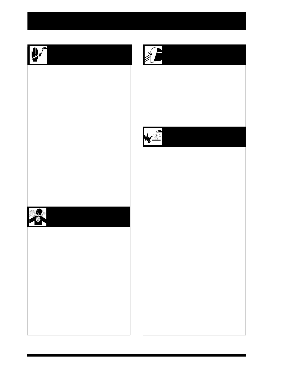
RANGER 405D
Part No. KA1453
Multi Process DC Welder & three phase 15 kVA
Auxiliary Power Generator - Diesel Engine driven
Engine - Kubota / Perkins
P R OTECT YOURSELF AND OTHERS FROM POSSIBLE SERIOUS INJURY OR DEATH. READ AND
U N D E R S TAND BOTH THE SPECIFIC INFORMATION GIVEN IN THE OPERATING MANUAL FOR THE
WELDER AND/OR OTHER EQUIPMENT TO BE USED AS WELL AS THE FO L L OW I N G GENERAL
ARC WELDING SAFETY PRECAUTIONS
1. a. The electrode and work (or ground) circuits are
electrically “hot” when the welder is on. Do not touch
these “hot” parts with your bare skin or wet clothing.
Wear dry, hole-free gloves to insulate hands.
b. In semi-automatic and automatic wire welding, the
electrode, electrode reel, welding head and nozzle or
semi-automatic welding gun are also electrically “hot”.
c. Insulate yourself from work and ground using dry
insulation. When welding in damp locations, on metal
framework such as floors, gratings or scaffolds, and
when in positions such as sitting or Lying, make certain
the insulation is large enough to cover your full area of
physical contact with work and ground.
d. Always be sure the work cable makes a good electrical
connec tion with the metal being welded. T h e
connection should be as close as possible to the area
being welded.
e. Ground the work or metal to be welded to a good
electrical (earth) ground.
f. Maintain the electrode holder, work clamp, welding
cable and welding machine in good, safe operating
condition. Replace damaged insulation.
g. Never dip the electrode holder in water for cooling.
h. Never simultaneously touch electrically “hot” parts of
electrode holders connected to two welders because
voltage between the two can be the total of the open
circuit voltage of both welders.
i. When working above floor level, protect yourself from
a fall should you get a shock.
j. Also see items 4c and 6.
2. a. Welding may produce fumes and gases hazardous to
health. Avoid breathing these fumes and gases. When
welding, keep your head out of the fume. Use enough
ventilation and/or exhaust at the arc to keep fumes and
gases away from the breathing zone. When welding
on galvanised, lead or cadmium plated steel and other
metals which produce toxic fumes, even greater care
must be taken.
b. Do not weld in locations near chlorinated hydrocarbon
vapours coming from degreasing, cleaning or spraying
operations. The heat and rays of the arc can react with
solvent vapours to form phosgene, a highly toxic gas,
and other irritating products.
c. Shielding gases used for arc welding can displace air
and cause injury or death. Always use enoug h
ventilation, especially in confined areas, to ensure
breathing air is safe.
d. Read and understand the manufacturer ’ s instructions
for this equipment and the consumables to be used,
including the material safety data sheet (MSDS) and
follow your employer’s safety practices.
e. Also see Item 7b.
3. a. Use a shield with the proper filter and cover plates to
protect your eyes from sparks and the rays of the arc
when welding or observing open arc welding.
Headshield and filter lens should conform to A S
1674.2-1990 standards.
b. Use suitabl e clothing made from durable flame
resistant material to protect your skin and that of your
helpers from the arc rays.
c. Protect other nearby personnel with suitable non
flammable screening and/or warn them not to watch
the arc or expose themselves to the arc rays or to hot
spatter or metal.
4. a. Remove fire hazards from the welding area. If this is
not possible, cover them to prevent the welding sparks
from starting a fire. Remember that welding sparks
and hot materials from welding can easily go through
small cracks and openings to adjacent areas. Have a
fire extinguisher readily available.
b. Where compressed gases are to be used at the job
site, special precautions should be used to prevent
hazardous situations. Refer to AS1674 Parts 1 & 2
“Safety in Welding and Allied Processes”, WTIA
Technical Note 7 “Health and Safety in Welding” and
the operating information for the equipment being
used.
c. When not welding, make certain no part of the
electrode circuit is touching the work or ground.
Accidental contact can cause overheating and create
a fire hazard.
d. Do not heat, cut or weld tanks, drums or containers
until the proper steps have been taken to insure that
such procedures will not cause flammable or toxic
vapours from substances inside. These can cause an
explosion even though the vessel has been “cleaned”.
For information purchase AS 1674-1990.
e. Vent hollow castings or containers before heating,
cutting or welding. They may explode.
f. Sparks and spatter are thrown from the welding arc.
Wear oil free protective garments such as leather
gloves, heavy shirt, cuffless trousers, high shoes and
a cap over your hair. Wear ear plugs when welding out
of position or in confined places. Always wear safety
glasses with side shields when in a welding area.
g. Connect the work cable to the work as close to the
welding area as possible. Work cables connected to
the building framework or other locations away from
the welding area increase the possibility of the welding
current passing through lifting chains, crane cables or
other alternate circuits. This can create fire hazards or
overheat lifting chains or cables until they fail.
h. Also see Item 7c.
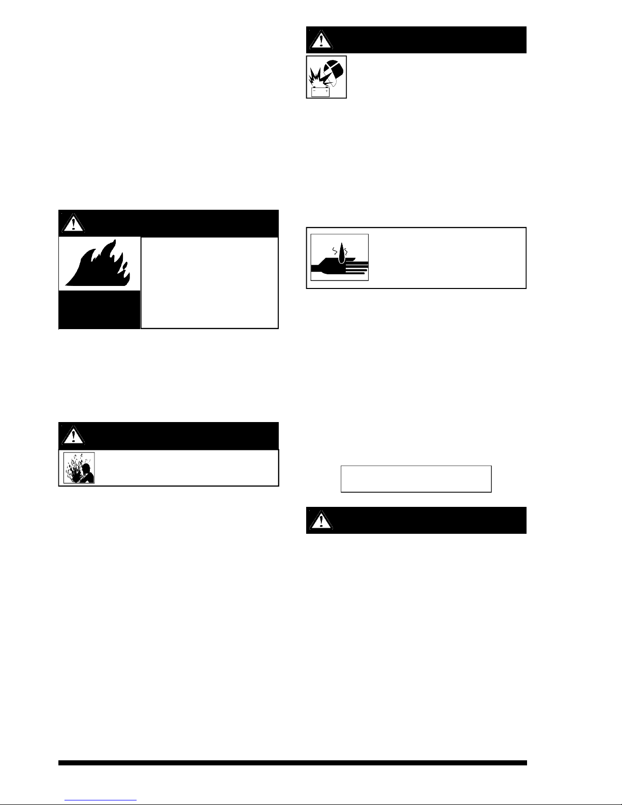
ELECTRIC SHOCK can kill
FUMES AND GASES
can be dangerous
A R C RAYS can burn
WELDING SPARKS can
cause fire or explosion
5. a. Use only compressed gas cylinders containing the
correct shielding gas for the proce ss used and
properly operating regulators, designed for the gas
and pressure used. All hoses, fittings, etc. should be
suitable for the application and maintained in good
condition.
b. Always keep cylinders in an upright position and
securely chained to an undercarriage or fixed support.
c. Cylinders should be located :
• Away from areas where they may be struck or
subjected to physical damage.
• A safe distance from arc welding or cutting
operations and any other source of heat, sparks or
flame.
d. Never allow the electrode, electrode holder, or any
other electrically “hot” parts to touch a cylinder.
e. Keep your head and face away from the cylinder valve
outlet when opening the cylinder valve.
f. Valve protection caps should always be in place and
hand-tight except when the cylinder is in use or
connected for use.
g. Read and follow the instructions on compressed gas
cylinders and associated equipment, and AS 2030
Parts 1 & 2.
6. a. Turn off input power using the disconnect switch at the
fuse box before working on the equipment.
b. Install equipment in accordance with the SAA Wiring
Rules, all local codes an d the manufac turer’s
recommendations.
c. Ground the equipment in accordance with the SAA
Wirin g Rules and the manufactur er’s
recommendations.
7. a. Turn the engine off before troubleshooting
and maintenan ce work unless the
maintenance work requires it to be running.
b. Operate engines in open, well ventilated
areas or vent the engine exhaust fumes
outdoors.
c. Do not add fuel near an open flame,
welding arc or when the engine is running.
Stop the engine and allow it to cool before
refuelling to prevent spilled fuel from
vaporizing on contact with hot engine
parts and igniting. Do not spill fuel when
filling tank. If fuel is spilled, wipe it up and
do not start engine until fumes have been
eliminated.
d. Keep all equipment, safety guards, covers
and devices in position and in good repair.
Keep hands, hair, clothing and tools away
from V-belts, gears, fans and all other
moving parts when starting, operating or
repairing equipment.
e. In some cases it may be necessary to
remove safety guards to perform required
maintenance. Remove guards only when
necessary and replace them when the
maintenance requiring their removal is
complete. Always use the greatest care
when working near moving parts.
f. Do not put your hands near the engine
fan. Do not attempt to over ride the
governor or idler by pushing on the throttle
control rods while the engine is running.
g. To prevent accidentally starting petrol
engines while tur ning the engine or
welding generator during maintenance
work, disconnect the spark plug wires,
distributor cap or magneto wi re as
appropriate.
h. To avoid scalding do not remove the
radiator pressure cap when the engine is
hot.
CYLINDER may explode if
damaged
FOR ELECTRICALLY
powered equipment
FOR ENGINE
powered equipment
HAVE ALL INSTALLATIONS, OPERATION, MAINTENANCE AND REPAIR WORK PERFORMED BY QUALIFIED PEOPLE
HOW TO ORDER REPLACEMENT PARTS
To ensure that you receive the correct replacement part the following procedure should be followed:
1. Quote Serial Number and Code Number.
2. Quote the Description, Item Number and Parts List Number of the desired part. When ordering parts for items carrying brand names
of other companies, such as fan motors, drive shafts, etc., be sure to include the other company’s name and part number and other
relevant information.
3. Should the primary cord be damaged, a special cord is required, and is available from Lincoln Electric.
4. Parts should be ordered from Lincoln, its offices or the nearest Authorised Field Service Shop. (The “Lincoln Service Directory” listing
these shops geographically is available on request.)
Note: “Hardware” in the Lincoln Parts Lists are not Lincoln stock items but can be obtained via the Field Service Shop network.
Component parts of assemblies such as stator coils or armature coils, etc., which require electrical testing or locating fixtures are not
considered replaceable items. This is to ensure that the customer receives parts which will keep the welder in the best operating condition.
BUY ONLY GENUINE REPAIR PARTS
For more detailed information it is strongly recommended that you purchase a copy of “Safety in Welding and Cutting - ANSI Standard Z
49.1” and WTIA Technical Note 7. All WTIA publications and ANSI/AWS Standards are available from the Welding Technology Institute of
Australia, P.O. Box 6165, Silverwater NSW 2128. For copies of various Australian Standards contact your local S.A.A. office.

VRD - VOLTAGE REDUCTION DEVICES
What are VRD & ROCV Devices?
VRD's are gaining popularity as a "must have" safety accessory
especially where welding applications are being carried out in an
environment with a high-risk of electric shock such as wet areas
and hot humid sweaty conditions.
VRD & ROCV are the abbreviations of two different naming
conventions used to describe safety device fitted to welding
power source to help protect the operator from electric shocks.
VRD stands for ‘Voltage Reduction Device’ and ROCV stands for
‘Reduced Open Circuit Voltage’ both devices are either fitted as
an after market addition or part of the integral design of a
machine. They reduce the voltage at the welding output terminals
whilst not welding to a no load voltage of no more than 35V for dc
welding and for AC welding 35V peak 25V a.c. rms, when the
resistance of the output circuit is below 200Ø (ohms). The lower
reactivation resistance is of the device the higher the safety level
but also requires that the welding cable connections be keep in
good electrical condition.
Having good electrical connections also limit the possibility of
other safety issues such as heat-generated damage, burns and
fires.
Welding Power Sources
Welding power sources generally have an Open Circuit Voltage
(i.e. the voltage at the welding output terminals whilst not welding)
in the ranges of 35 – 115VDC. Welding machines for stick
welding (MMAW) and similar constant current (CC) processes,
supply a higher open circuit voltage between the electrode and
the work when the welding machine is switch on and ready to
commence welding. These welding machines have a drooping
characteristic, with the open circuit voltage higher (typically
60-80V) than when the arc is established and welding current is
drawn (20-35V).
Consequently, the greatest danger occurs when handling the
electrodes and the electrode holder between welding operations,
such as when changing electrodes.
Welding machines for MIG (GMAW & FCAW) have a flat constant
voltage (CV) characteristic, generally with a lower open circuit
voltage (30-60V). Also, the current is turned on & off by a gun
trigger, which also controls the wire feed. Therefore, the welder is
not exposed to open circuit voltage, unless the trigger is turned on
and the wire is feeding. Also, electrodes are not changed as
frequently as for stick welding (MMAW).
For these reasons VRD/ROCV’s are more common ly
incorporated into the stick welding mode (CC) of welding
machines being used in environments with high-risk of electric
shock.
All multi-process CC/CV machines which are fitted with VRD’s do
not offer low voltage protection in CV modes. If the multi-process
machine has a “WELD TERMINAL ENABLE SWITCH” enabled,
the weld outpu t terminals will be electrically ‘HOT’ a n d
potentially High Voltage present.
Only ‘ACROSS THE ARC’ type wire feeders with a internal
contactor fitted should be used in this configuration.
Arc air gouging is not recommended in CV. Due to ‘CV MODE’
not offering VRD protection.
This reduction of the voltage supplies a safer level of voltage
when an arc is not being struck or when an electrical resistance
less than the welder’s body resistance have been detected.
All VRD’s are only an aid to safety and personal protective
equipment and safe working practices must be observed at all
times. The risk of electric shock during welding from a correctly
installed and maintained welding machine is negligible, provided
that sensible precautions are taken by the user and correct safe
working procedures are followed. All parts of the output circuit
should be considered electrically alive, and consequently welders
should ensure that no part of their body is placed in such a
position as would complete a path through it for the passage of
electric current. Safe working procedures should always be
followed whether a VRD is fitted or not.
Operation
Due to inherit low voltage safety features of the VRD’s to reduce
the possibility of electric shock to the operator. A very slight delay
during striking of the electrode may be experienced. The high
voltage that is available on units without VRD’s allows them to
penetrate and burn through dirty, painted and heavily mill scale
plate. Units fitted with VRD’s cannot penetrate and are required
to register the correct resistance, which switches the safety
device into weld mode. Unlike other VRD’s Lincoln uses micro
processor control to monitor and establish the arc without the
sticking and shorting of the electrode to the job as seen in many
other VRD installations. Due to the requirement of the resistance
in the c ircuit to be low for a VRD to ope rate, a good
metal-to-metal contact must be made between the metal core of
the electrode and the job. A damaged or poor connection
anywhere in the output circuit may limit the operation of the VRD.
Some electrodes form a cone at the end of the electrode after the
welding arc has been broken, particularly iron powder and low
hydrogen electrodes. This cone will need to be broken off in order
to have the metal core of the electrode to make contact.
Safe working procedures should always be followed whether
a VRD is fitted or not.
W A R N I N G

WELDING, EMF & PACEMAKERS
All welders should follow safe practices that minimise their
exposure to electric and magnetic fields (EMF).
For welders wearing implanted pacemaker s, safe welding
practices are particularly important and additional procedures
should be followed by those who have decided to continue to
weld. (Hopefully in keeping with a doctor’s advice).
The following procedures will not eliminate exposure to EMF or
the possibility of arc welding having an effect on a pacemaker,
however if followed, they will significantly reduce exposure to
electric and magnetic fields. Electric and magnetic fields are
created any time electric current flows through a conductor,
however it is not clear whether such exposure affects ones
health.
Some researchers have reported that exposure to EMF may
cause leukemia or other illnesses. These claims originally arose
in relation to high voltage electric power lines and are very much
in dispute in the medical and scientific arena, however the best
advice is to minimise your exposure to EMF to protect your health
should doctors eventually decide there is a risk.
There are four fundamental facts about EMF:
• With direct current (DC), the field strength is relatively
constant and does not change.
• With alternating current (AC), the field strength constantly
changes.
• The greater the current flow, i.e. the higher the amps, the
stronger the field created by the current
• The closer the conductor or electrical device is to the body,
the greater the exposure to the field.
Minimising exposure
All welders should use the following procedures to minimise EMF
exposure.
• Route electrode or gun and work cables together. Secure
them with tape if possible.
• Never coil the electrode lead around your body.
• Do not place your body between the electrode and work
cables. If your electrode cable is on your right side the work
cable should also be on your right side.
• Connect the work cable to the work piece as close as
possible to the area being welded. (This is also a good
practice to eliminate a common problem on welding - a poor
work connection.
• Do not work next to the welding power source.
Welders with pacemakers
There is no question that the fields in arc welding can interfere
with a pacemakers function. Generally the interference does not
permanently damage the pacemaker. Once the wearer leaves the
arc welding environment or stops welding, the pacemaker returns
to normal functioning. The welding arc has little or no effect on the
operation of some pacemakers, especially designs that are bipolar or designed to filter out such interference.
For a welder or anyone working around electrical equipment the
selection of a pacemaker is very important. Get a doctor’s advice
about which pacemaker is the least sensitive to interference from
welding while still being medically suitable.
In addition to the normal safety precautions, the following
additional procedures should be adopted by welder s with
pacemakers.
• Use gas welding when the application is suitable.
• Use the lowest current settin g appropriate for the
application. Do not exce ed 400 amps . Low current
(75-200 amps) direct current (DC) welding should be used if
arc welding is necessary. Do not TIG weld with high
frequency.
• Do not use repeated, short welds. Wait about ten seconds
between stopping one weld and starting the next. When
having difficulty starting an electrode, do not re-strike the rod
repeatedly.
• If you feel light headed, dizzy or faint, immediately stop
welding. Lay the electrode holder down so that it does not
contact the work and move away from any welding being
performed. Arrange your work in advance so that, if you
become dizzy and drop the electrode holder, the electrode
holder will not fall on your body or strike the work.
• Do not work on a ladder or other elevated position or in a
cramped, confined place.
• Do not work alone. Work only in the presence of an
individual who underst ands these precautions and the
possible effect welding may have on your pacemaker.
• Do not work near spot welding equipment.
• If you have a pacemaker and wish to continue arc welding,
discuss this and any other questions you may have with your
physician and follow his or her advice. The doctor may wish
to contact the pac emaker manufac turer for a
recommendation. As mentioned before, the design of the
pacemaker significantly affects the degree to which it is
subject to interference from a welding circuit. Do not rely on
the fact that you know another welder with a pacemaker who
has welded for years without experiencing a problem. That
welder and his or her pacemaker may be quite different from
you and your pacemaker.

Conformance
Products displaying the C-Tick mark are in conformity with
Australian/ New Zealand requirements for Elec tromagnet ic
Compatibility (EMC). They are:
• manufactured in conformity with Australian/New Zealand
Standa rd (Emission):- AS/NZS 36 52 ‘Electromagnet ic
Compatibility - Arc Welding Equipment’ (Identical to and
reproduced from British Standard EN 50199)
• for using with other Lincoln Electric/LiquidArc equipment.
• designed for industrial and professional use.
Introduction
All electrical equipment generates small amounts of electromagnetic emission. Electrical emission may be transmitted through
power lines or radiated through space, similar to a radio
transmitter. When emissions are received by other equipment,
electrical interference may result. Electrical emissions may effect
many kinds of electrical equipment: other nearby welding
equipment, radio and TV transmitters and receivers, numerical
controlled machines, telephone systems, computers, etc. Be
aware that interference may result and extra precautions may be
required when a welding power source is used in a domestic
establishment.
Installation and Use
The purchaser/user is responsible for installing and using the
welding equipment according to the manufacturer’s instructions.
If electromagnetic disturbances are detected then it shall be the
responsibility of the purchaser/user of the welding equipment to
resolve the situation with the technical assi stanc e of the
manufacturer. In some cases this remedial action may be as
simple as earthing (grounding) the welding circuit (see note
below). In other cases it could involve constructing an electromagnetic screen enclosing the power source and the work
complete with associated input filters. In all cases electromagnetic disturbances must be reduced to the point where they are no
longer troublesome.
Note: The welding circuit may or may not be earthed for safety
reasons according to national codes. Changing the earthing
arrangements should only be authorised by a person who is
competent to assess whether the changes increase the risk of
injury, eg. by allowing parallel welding current return paths which
may damage the earth circuits of other equipment.
Assessment of Area
Before installing welding equipment the purchaser/user shall
make an assessment of potential problems in the surrounding
area.
The following shall be taken into account:
a. Other supply cables, control cables, signalling and telephone
cables above, below and adjacent to the welding equipment;
b. Radio and television transmitters and receivers;
c. Computer and other control equipment;
d. Safety critical safety equipment, eg. guarding of industrial
equipment;
e. The health of people around, eg. the use of pacemakers and
hearing aids;;
f. Equipment used for calibration or measurement;
g. The immunity of other equipment in the environment. The
purchaser/user shall ensure that other equipment being used
in the environment is compatible. This may require additional
protection measures;
h. The time of the day that welding or other activities are to be
carried out.
The size of the surrounding area to be considered will depend on
the structure of the building and other activities that are taking
place. The surrounding area may extend beyond the boundaries
of the premises.
Methods of Reducing Emissions
Mains Supply
Welding equipment should be connected to the mains supply
according to the manufacturer’s recommendations.If interference
occurs, it may be necessary to take additional precautions such
as filtering the mains supply. Consideration should be given to
shielding the supply cable of permanently installed welding
equipment in metallic conduit or equivalent. Shielding should be
electrically continuous throughout its length. The shielding should
be connected to the welding power source so that good electrical
contact is maintained between the conduit and the welding power
source enclosure.
Maintenance of the Welding Equipment
The welding equipment should be routinely maintained according
to the manufacturer’s recommendations. All access and service
doors and covers should be closed and properly fastened when
the welding equipment is in operation. The welding equipment
should not be modified in any way except for those changes and
adjus tmen t c overed in the m anufactu rer ’s instructions. In
particular, the spark gaps of arc initiation and stabilising devices
should be adjusted and maintained ac cording to the
manufacturer’s recommendations.
Welding Cables
The welding cables should be kept as short as possible and
should be positioned close together, running at or close to the
floor level.
Equipotential Bonding
Bonding of all metallic components in the welding installation and
adjac ent to it should be considered. Howev er, met allic
components bonded to the work piece will increase the risk that
the operator could receive a shock by touching these metallic
components and the electrode at the same time. The operator
should be insulated from all such bonded metallic components.
Earthing of the workpiece
Where the workpiece is not bonded to earth for electrical safety,
nor connected to earth because of its size and position, eg. ship’s
hull or building steelwork, a connection bonding the workpiece to
earth may reduce emissions in some, but not all instances. Care
should be taken to prevent the earthing of work pieces increasing
the risk of injury to users, or damage to other electrical
equipment. Where necessary, the connection of the workpiece to
earth should be made by direct connection to the workpiece, but
in some countries where direct connection is not permitted, the
bonding should be achieved by suitable capacitance, selected
according to national regulations.
Screening and Shielding
Selective screening and shielding of other cables and equipment
in the surrounding area may alleviate problems of interference.
Screening of the entire welding installation may be considered for
special applications.*
* Portions of the preceding text are cont ained in A S / N Z S 3 6 5 2 :
‘Electromagnetic Compatibility - Arc Welding Equipment’.
INSTRUCTIONS FOR ELECTROMAGNETIC COMPATIBILITY
This welding machine must be used by trained operators
only. Read this manual carefully before attempting to use
the welding machine.
W A R N I N G
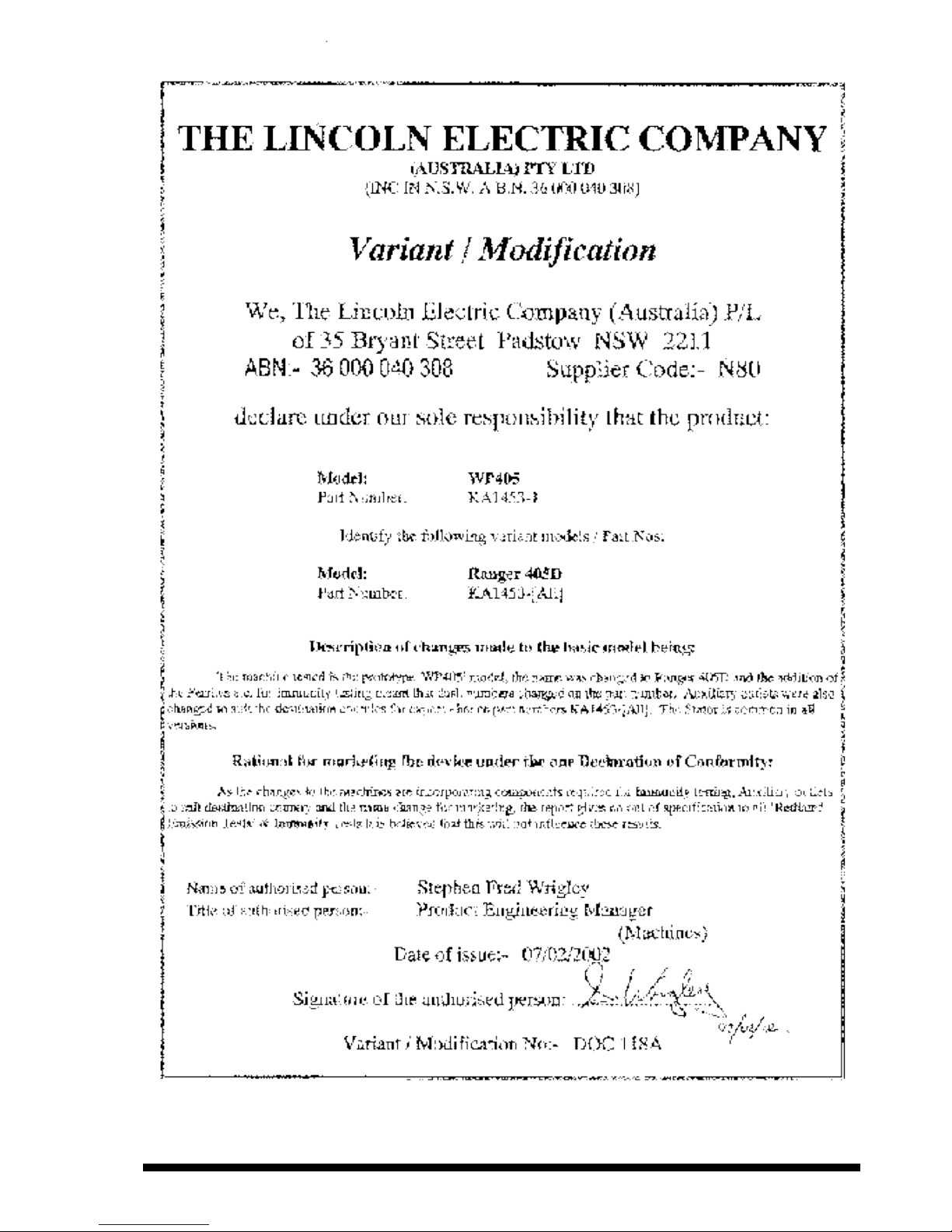
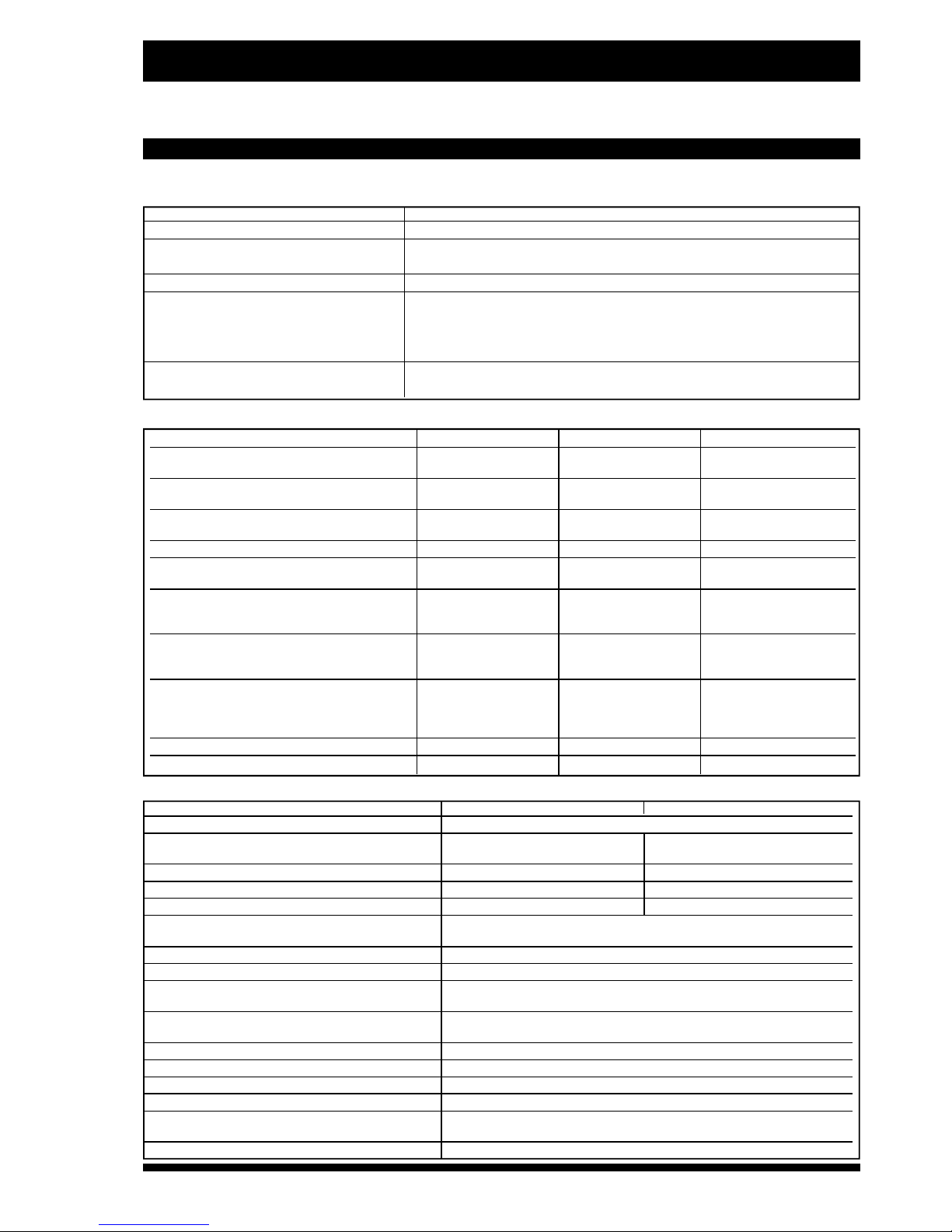
PRODUCT DESCRIPTION
The Ranger 405D is a diesel engine driven alternator power source for multi-process DC welding and for 115/230-240/400-415VAC
auxiliary* and standby power. It is housed in a sound reduced enclosure for quiet operation.
* Auxiliary outlets and circuit breakers depend on model purchased.
THE RANGER 405D IS NOT RECOMMENDED FOR PIPE THAWING
Part Number
KA1453-1, KA1453-2, KA1453-3, KA1453-4, KA1453-5, KA1453-6, KA1453-7, KA1453-20
DC Constant Current – Current Range 30 to 405 Amps
Maximum OCV – Reduced OCV (VRD) 62 Volts – Reduced < 8 Volts
Arc Force Control Factor x 1 to x 2.6
DC Constant Voltage – Open Circuit Range 15 to 49 Volts
Ratings:-
Low Inductance Receptacle 400 Amp @ 20 Volt 30% Duty Cycle
350Amp @ 30Volt 60% Duty Cycle
300Amp @ 32Volt 100% Duty Cycle
High Inductance Receptacle 335Amp @ 30Volt 50% Duty Cycle
250Amp @ 30Volt 100% Duty Cycle
Machine Specifications - Welding
Auxiliary Power - (When welding, maximum available auxiliary power is reduced)
Part Number KA1453-1,-4, -7 & -20 KA1453-2 &-5 KA1453-3 & -6
Ratings (Factory set) voltage regulation 415V (3 Ph) & 400V (3 Ph) & 230V (1 Ph) & 400V (3 Ph)
is within +/-7% @ all loads up to rated capacity) 240V (1 Ph) 230V (1 Ph) 115V (Centre Tapped Earth)
Total Loading (100% Duty Cycle) 15kVA @ Unity 14.4kVA @ Unity 14.4kVA @ Unity
12kW @ 0.8pf 11.5kW @ 0.8pf 11.5kW @ 0.8pf
Wire Feeder Supply 115V @ 5 Amps AC & 115V @ 5 Amps AC & 115V @ 5 Amps AC
42V @ 10 Amps AC 42V @ 10 Amps AC 42V @ 10 Amps AC
Frequency 50Hz 50Hz 50Hz
Automatic Electronic Voltage Regulator (AVR) 115/230/400V
Factory set for 240/415V Output 230/400V Output 115V Output
Protection & Receptacles
Residual Current Device (RCD) 4 Pole, 25 Amp, 4 Pole, 25 Amp, 4 Pole, 25 Amp
(30mA Trip Current) (30mA Trip Current) (30mA Trip Current)
Thermal / Magnetic Circuit Breakers 3 Ph 20 Amp x 1 & 3 Ph 20 A, x 1 & 3 Ph 20 Amp x 1
1 Ph 16 Amp x 3 1 Ph 16 Amp x 2 1 Ph 16 Amp x 1
2 Ph 20 Amp x 1
Receptacles 415V (3 Ph) x 1 400V (3 Ph) x 1 400V (3 Ph) x 1
240V (1 Ph) x 3 230V (1 Ph) x 2 230V (1 Ph) x 1
14 pin Amphenol x 1 14 pin Amphenol x 1 115V (1Ph) x 3
14 pin Amphenol x 1
Dimensions approx. L x W x H 1600 x 733 x 970 1665 x 733 x 970 1665 x 733 x 970
Weight approx. 550 kg 550kg 550kg
Make / Model Kubota / D1105 Perkins / 403C-11
Type 3 Cyl., Water cooled, 4 Cycle, Diesel
Combustion Chamber Spherical type; 3 Vortex Naturally aspirated
Combustion System Indirect injection
Bore & Stroke 78 x 78.4mm 77 x 81mm
Displacement 1124cc 1131cc
Power (SAE, J1349 net intermittent) 18.6kW @ 3000rpm 19.6kW @ 3000rpm
Electrical System 12V Battery & Starter, Key Start & Stop, Glow Plugs, Alternator
Battery Charger (internal regulator)
Governor Type Centrifugal (flywheel high speed mechanical)
Lubrication Forced feed full flow oil filter
Cooling System Pressurised (0.9 kg/cm2) Radiator. Pump forced circulation,
capacity is 4L and an overflow reservoir bottle.
Fuel System Indirect injection pre fitted to fuel filter with shut off, lift pump, bypass valve
for easy bleeding.
Fuel Tank Capacity 45 litres
Air Cleaner Heavy Duty, 2 Stage dry cartridge type
Engine Idler Automatic (with manual over-ride)
Muffler Low Noise
Engine Protection System with ‘First Alarm’ Shutdown on - High electricals temperature, High coolant
latched LED indication temperature, Low oil pressure, welding output failure
Operating Speeds (approximate) High Idle - 3130rpm Low Idle - 1580rpm Full Load - 3000rpm
Engine Specifications
Technical Specifications
Before Starting your Welder
Pre-Operation Service
READ the engi ne operating and maintenanc e instructions
supplied with this machine.
Oil
The Ranger 405D is shipped with the engine crankcase filled with
the correct grade oil for the run-in period. Check the oil level
before starting the engine. If it is not up to the full mark on the dip
stick, add oil as required. Check the oil level every four hours of
running time during the first 35 running hours. Refer to the engine
Operator’s Manual for specific oil recommendations and run-in
information.
Fuel - use diesel fuel only
Fill the fuel tank with clean, fresh diesel fuel. The capacity is 45
litres. See engine Operator’s Manual for specific fuel recom-
mendations. Do not allow the Ranger 405D to run out of fuel.
This necessitates bleeding the injector system.
Engine Coolant
The welder is shipped with the engine and radiator filled with
engine coolant. Before starting the engine check coolant level in
the radiator, add more pre-mixed coolant if required. See
Maintenance Section and engine Operator’s Manual for more
information on coolant.
Battery
Important: In order that control electronics will function
correctly, the Ranger 405D must always have its battery
connected whenever its engine is running. The battery must
be in good condition, and fully charged.
GASES FROM BATTERY CAN EXPLODE.
• Keep sparks, flame and cigarettes away
from battery.
To prevent Explosion when:
• Installing a new battery - disconnect negative cable from
old battery first and connect to new battery last
• Connecting a battery charger - remove battery from welder
by disconnecting negative cable first, then positive cable and
battery clamp. When reinstalling, connect negative cable last.
Keep well ventilated.
• Using a booster - connect positive lead to battery first then
connect negative lead to the chassis/engine strap.
THE RANGER 405D IS FURNISHED WITH A
WET CHARGED BATTERY
Battery Connection Instructions
The Range r is shipped with the negat ive batter y cable
disconnected. Before you operate the machine, make sure the
Key Switch is in the OFF position and attach the disconnected
cable securely to the negative (-) battery terminal.
Note: This machine is furnished with a wet charged battery; if
unused for an extended time, the battery may require a booster
charge. Be sure to use the correct polarity when charging the
battery. (If the battery terminal voltage is less than 12.47 volts,
then it will need recharging
before
use).
• Battery electrolyte contains sulphuric acid which is corrosive
to skin and clothing.
• Batteries also discharge explosive gases.
• When charging provide adequate ventilation to allow the safe
escape of explosive gases.
• Do not do anything to cause sparks near the battery. Keep
naked flames and cigarettes away from battery.
• If acid contacts eyes or skin flush immediately with large
quantities of clean drinking water.
• In case of acid contacting eyes, consult a doctor immediately.
• After use wash out empty electrolyte bottles with water and
dispose of carefully - do not use empty electrolyte bottles for
any other purpose.
• Always keep batteries and electrolyte out of reach of children.
• Dispose of old batteries carefully.
Important Note: Battery must not be filled or “topped
up” whilst it is in normal operating position - always
remove from machine.
Battery acid can burn eyes and skin
•Wear gloves and eye protection and be
careful when working near battery.
•Follow instructions printed on battery.
DIESEL fuel
can cause fire or
explosion
• Stop engine when fuelling.
• Do not smoke when fuelling.
• Remove cap slowly to release pressure.
• Do not overfill tank.
• Wipe up spilled fuel and allow fumes to
clear before starting engine.
• Keep sparks and flame away from tank.
HOT COOLANT CAN BURN SKIN
Do not remove cap if radiator is hot.
W A R N I N G
W A R N I N G
W A R N I N G
W A R N I N G
Angle of Operation
Engines are designed to run in the level condition which
is where the optimum performance is achieved. The maximum
angle of operation for the Kubota engine and Perkins engine is
20° continuously in any direction. If the engine must be operated
at an angle, provisions must be made for checking and
maintaining the oil level at the normal (FULL) oil capacity in the
crankcase.
When operating the welder at an angle, the effective fuel capacity
will be slightly less than the specified 45 litres.
High Altitude Operation
At higher altitudes, output derating may be necessary. As a rule
of thumb, derate the welder output 0.4% for every 30m above
150m.
Contact Kubota/Perkins Service Representative for any engine
adjustments that may required.
Optional Field Installed Accessories
KA1373 Power Plug Kit (suits KA1453-1, -4, -7 & -20 415/240V
Australian plugs)
KA1373-3 Power Plug Kit (suits KA1452-5 400/380/230/220V
Provides a plug for each auxiliary power receptacle.
KIT400 Accessory Kit
Includes:- Electrode Holder, ground clamp, flip front Headshield,
supervisibility lens, Non-spat ter lens, wire brush, chipping
hammer.
KIT1600T Lead Kit
Includes:- One 10m & one 9m length of 50mm2cable with one
Twistmate connector fitted to each.
K857 Remote Control (Weld Control)
Portable control provides same dial range as the output control
on the welder from a location up to away from the welder. Has
convenient plug for easy connection to the welder. (Requires
K864 or K876 Adapter).
Refer Optional Equipment Section in this manual for cable length
and plug options.
K864 Remote Control Adapter
Plugs into the 14 pin remote output control plug base mounted on
the machine. It provides a 14 pin and a 6 pin remote output
connection. e.g. Used for K857 remote control and ‘plug’ cable
LN-7 connections.
K876 Remote Control Adapter
Plugs into the 14 pin remote output control plug base mounted on
the machine. It provides a 6 pin connector. e.g. Used for K857
remote control.
K867 Universal Adapter Plug
Plugs into the 14 pin remote output control plug base mounted on
the machine. It provides flying leads for connection to ‘lugged’
control cables. e.g. Used for K775 remote control and ‘lugged’
cable LN-7 connections.
K930-2 Hi-Freq TIG Module
High frequency unit with gas valve for TIG welding. Rating is 250
amp @ 80% duty cycle.
INSTALLATION INSTRUCTIONS
Location / Ventilation
Do not touch electrically live parts such as output terminals
or internal wiring
Use in open, well ventilated areas or vent exhaust outside.
• Do not operate with doors open or guards off.
• Stop engine before servicing.
Keep away from moving parts.
Only qualified personnel should install, use, or service this
equipment.
The welder should be located to provide an unrestricted flow of
clean, cool air to the cooling air inlets and to avoid heated air
coming out of the back of the welder recirculating back to the
cooling air inlets. Also, locate the welder so that the engine
exhaust fumes are properly vented to an outside area.
Machine Earthing
Standards Australia advise that "There is no need for an earth
electrode to be used with an engine driven welding power
service" E W Robson Projects Manager Committee EL/1 (7th
September 1998).
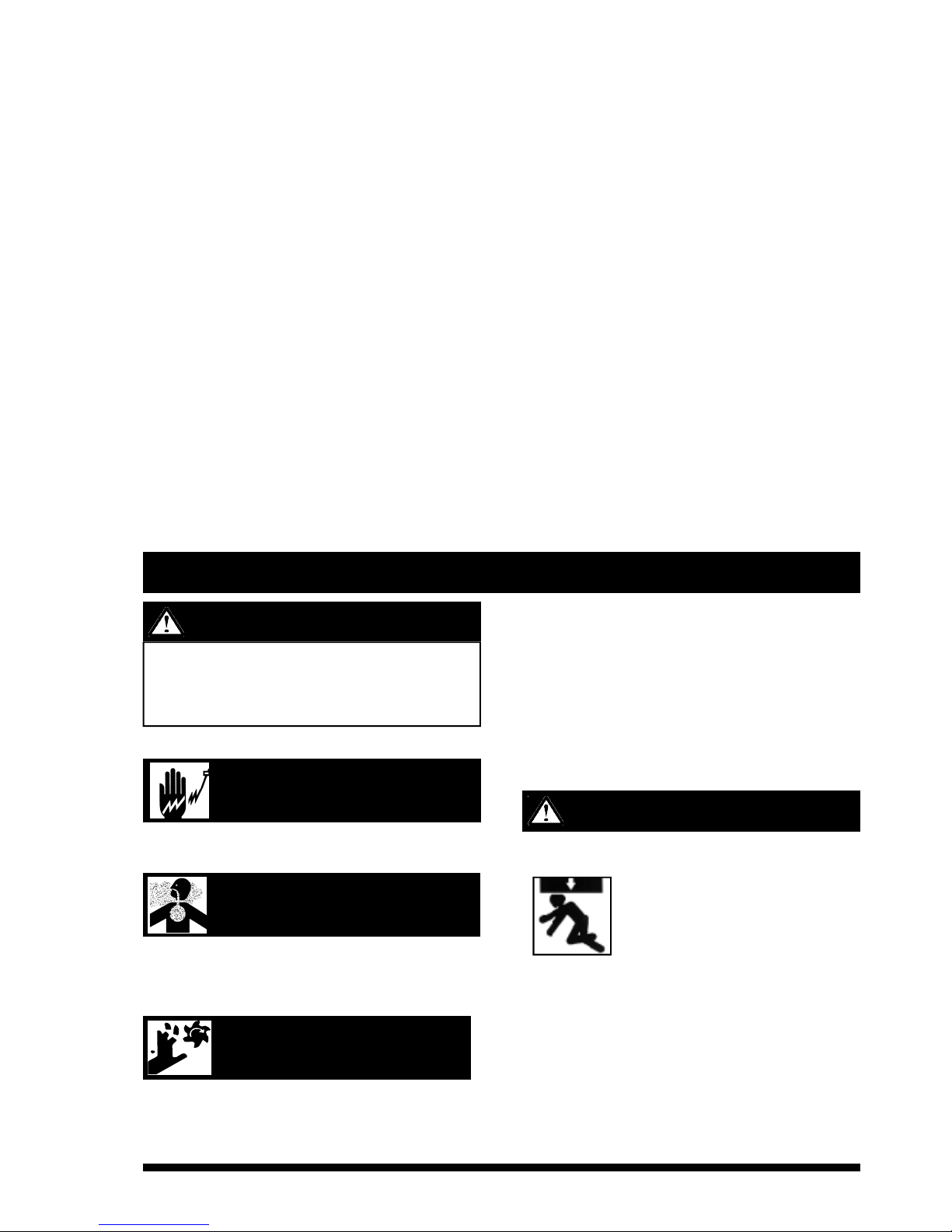
FALLING EQUIPMENT CAN CAUSE INJURY
• Do not lift this machine using lift bale if it
is equipped with a heavy accessory such
as trailer or gas cylinder.
• Lift only with equipment of adequate
lifting capacity.
• Be sure machine is stable when lifting
E N GINE EXHAUST
can kill
M O V I N G PA R TS
can injure
ELECTRIC SHOCK can kill
W A R N I N G
Do not attempt to use this equipment until you have
thoroughly read the engine manufacturer’s manual supplied
with your welder. It includes important safety precautions,
detailed engine starting, operating and maintenance
instructions, and parts lists.
W A R N I N G
High Frequency Generator for TIG Welding
Applications
The K930-2 TIG Module is suitable for use with the Ranger 405D.
The Ranger 405D and any high frequency generating equipment
must be properly grounded. See the K930-2 Operating Manual for
completed instruc tion s on installati on, operation, and
maintenance.
A T1224 6 BYPASS CAPA C I T OR A S S E M B L Y M U S T B E
I N S T ALLED IN THE RANGER 40 5D TO PROTECT T H E
RANGER 405D FROM DAMAGE.
Standby Power Connections
The Rang er 405D is suitable for tempor ary, standb y or
emergency power usi ng the eng ine manufac turer’s
recommended maintenance schedule.
The Ranger 405D can be permanently installed as a standby
power unit for:-
KA1453-1, -4 & -7 415/240V - 20 Amp service,
KA1453-2 & -5 400/230V - 20 Amp service
KA1453-3 & -6 400/230 and 115V (Centre Tapped Earth) - 20
Amp service.
Connections must be made by a licensed electrician who can
determine how the connections can be made to adapt to
particular installations and comply with all applicable electrical
codes, eg Australian Standard AS3000 Wiring Rules, and
maintain operation of the Residual Current Device.
Welding Output Cables
With the engine off, connect the electrode and work cables to the
appropriate receptacles.
Copper cables sizes listed below are recommended for the rated
current and duty cycle. Lengths stipulated are the distance from
the welder to work and back to the welder again. Cable sizes are
increased for gr eater lengths primarily for the purpose of
minimising cable voltage drop.
Remote Output Control
The Ranger 405D is fitted with a 14 pin remote control receptacle.
This receptacle is mounted between the output studs on the
control panel and is used for connection remote equipment, eg.
The control cable for an LN-21 wire feeder. Wen remote output
control is used the ‘local/remote’ toggle switch must be set at the
‘REMOTE’ position, otherwise set it at ‘LOCAL’ position for control
at machine nameplate.
Twist-Mate Welding Cable Plug
Installation Instructions
Turn the engine “OFF” before connecting or disconnecting plugs
to welding power source.
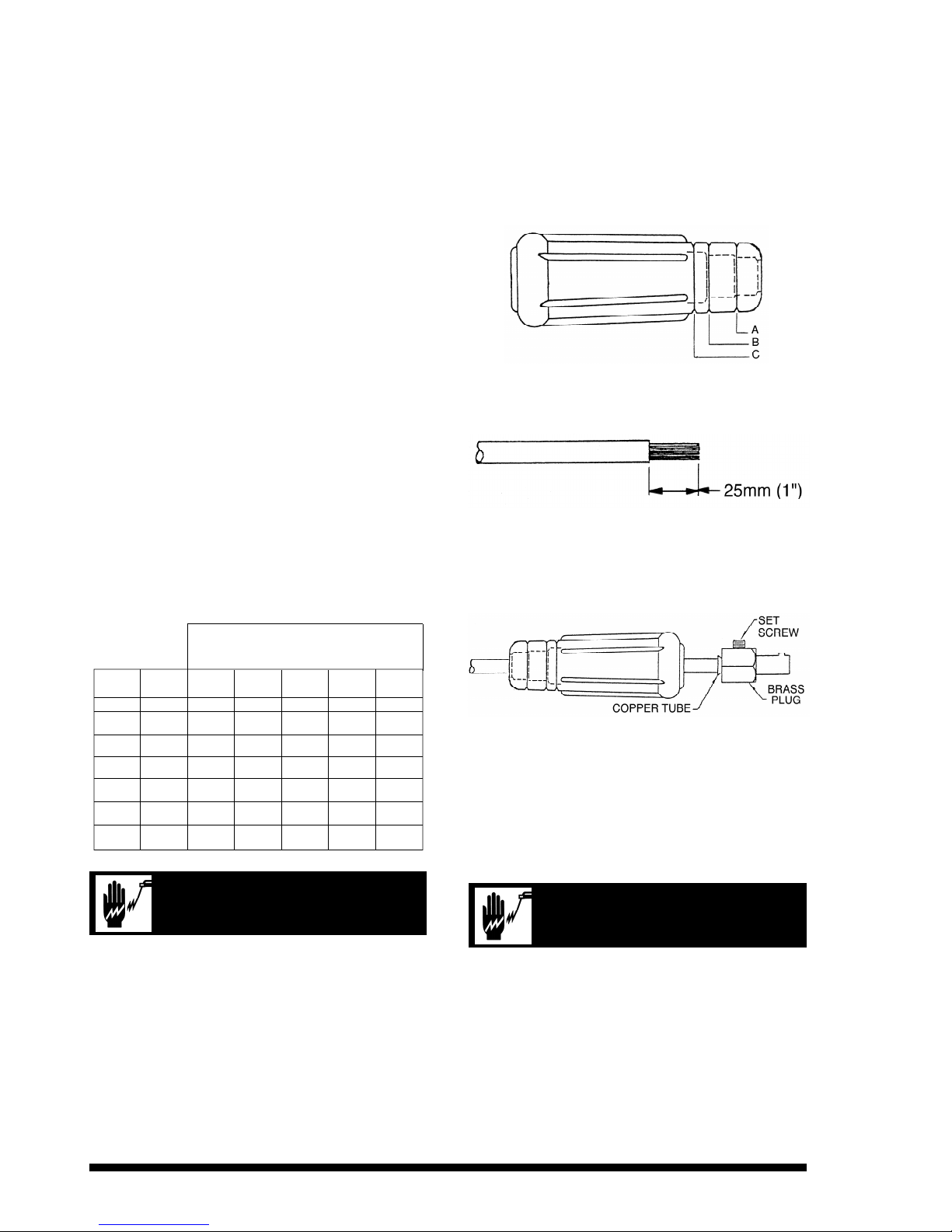
1. The connector is suitable for cable sizes 25 to 95mm2.
2. Trim rubber boot as required (see diagram).
25/35mm2Cable: No trim
50mm2Cable: Trim at “A”
70mm2Cable: Trim at “B”
95mm2Cable: Trim at “C”
3. Slide rubber boot on to cable end (soap or other lubricant may
be required to help slide the boot over the cable).
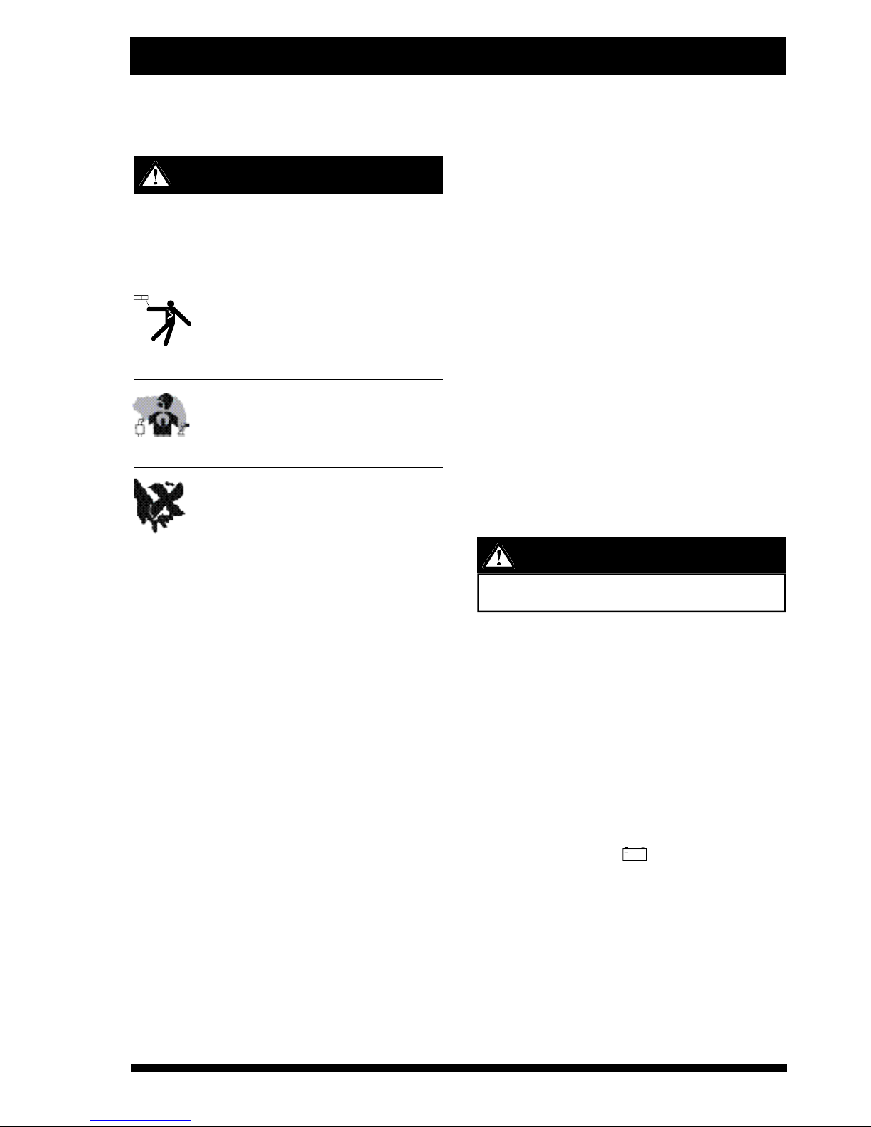
4. Strip the outer sheath of the welding cable 25mm.
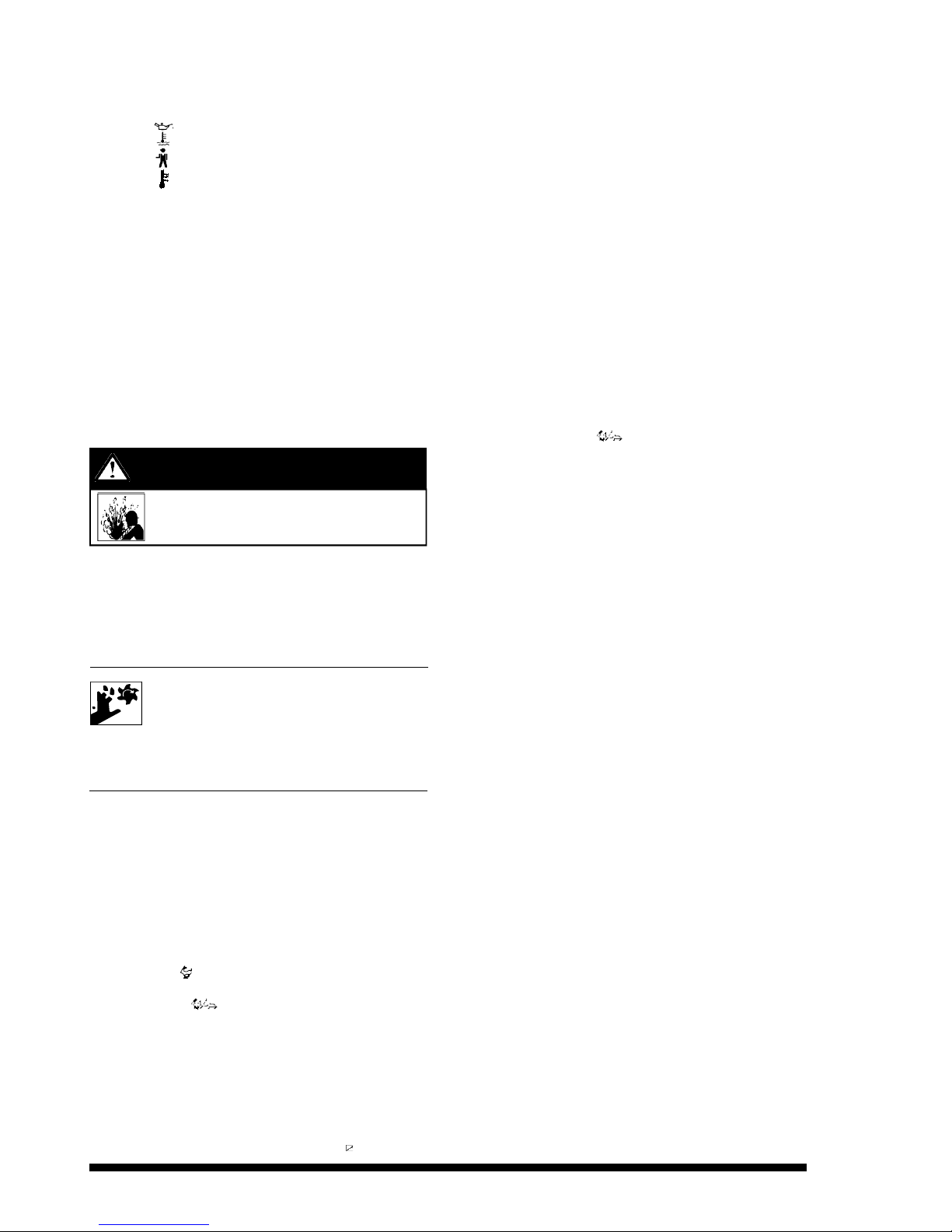
5. Slide the copper tube into the brass plug. (Use only the
largest dia. tube for 95mm2cable. Use both tubes for all other
cable sizes).
6. Insert cable into copper tube.
7. Tighten set screw to collapse copper tube. Screw must apply
pressure against welding cable. The top of the set screw will
be well below the surface of the brass plug after tightening.
8. Slide rubber boot over brass plug. The rubber boot must be
positioned to completely cover all electrical surfaces after the
plug is locked into the receptacle.
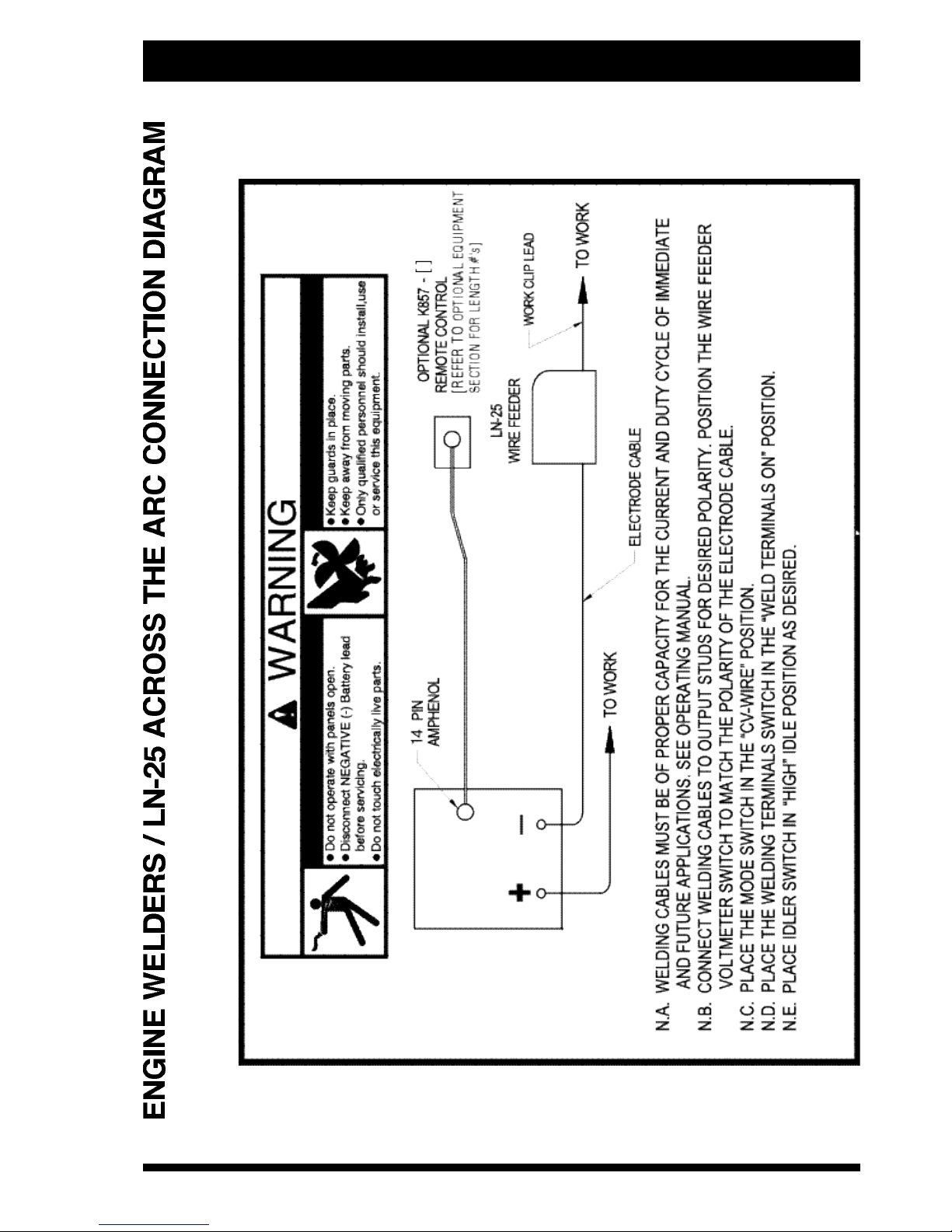
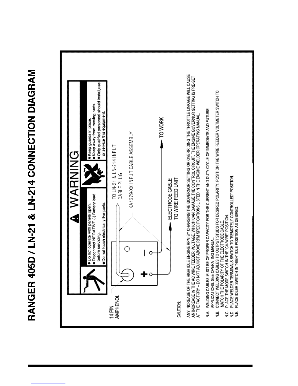
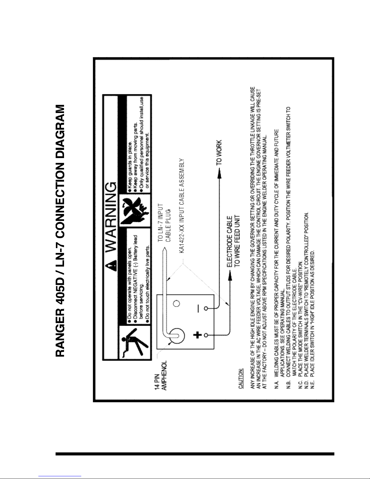
Connection of Lincoln Electric Wire Feeders
• Do not operate with covers removed.
• Disconnect power source before servicing.
• Do not touch electrically live parts.
• Only qualified persons should install, use or service this
machine.
Note:- The (–)ve “High Inductance” output receptacle is for
stick welding only, all other cases covered in this section use
the “Low Inductance” receptacle.
AMPS DUTY 0 - 15 15 - 30 30 - 45 45 - 60 60 - 75
CYCLE m m m m m
250 40 35mm235mm250mm250mm250mm
2
250 100 50mm250mm250mm250mm250mm
2
300 40 50mm250mm250mm250mm250mm
2
300 60 50mm250mm250mm250mm270mm
2
300 100 70mm270mm270mm295mm295mm
2
350 60 50mm250mm270mm270mm295mm
2
400 30 50mm250mm250mm270mm270mm
2
TOTAL COMBINED LENGTH OF
ELECTRODE & WORK CABLE
ELECTRIC SHOCK can kill
ELECTRIC SHOCK can kill
OPERATING INSTRUCTIONS
Safety Instructions
Read and understand this entire section before operating your
Vantage.
Do not attempt to use this equipment until you have
thoroughly read all operating and maintenance manuals
supplied with your machine. They include important safety
preca utions, detailed en gine starting, operating and
maintenance instructions and parts lists.
ELECTRIC SHOCK can kill.
• Do not touch electrically live parts such
as output terminals or internal wiring.
• Insulate yourself from the work and
ground.
• Always wear dry insulating gloves.
ENGINE EXHAUST can kill.
• Use in open, well ventilated areas or vent
exhaust outside.
• Do not stack anything near the engine.
MOVING PARTS can injure.
• Do not operate with doors open or guards
off.
• Stop engine before servicing.
• Keep away from moving parts.
Only qualified personnel should operate this equipment.
VRD (Voltage Reduction Device)
Welding power sources generally have an Open Circuit Voltage
(i.e. the voltage at the welding output terminals whilst not welding)
in the ranges of 35-115VDC. Welding machines for stick welding
(MMAW) and similar constant current (CC mode) processes,
supply a higher open circuit voltage between the electrode and
the work when the welding machine is switch on and ready to
commence welding. These welding machines have a drooping
characteristic, with the open circuit voltage higher (typically
60-80V) than when the arc is established and welding current is
drawn (20-35V).
Consequently, the greatest danger occurs when handling the
electrodes and the electrode holder between welding operations,
such as when changing electrodes.
Welding machines for MIG (GMAW & FCAW) have a flat constant
voltage (CV) characteristic, generally with a lower open circuit
voltage (30-60V). Also, the current is turned on & off by a gun
trigger, which also controls the wire feed. Therefore, the welder is
not exposed to open circuit voltage, unless the trigger is turned on
and the wire is feeding. Also, electrodes are not changed as
frequently as for stick welding (MMAW).
For th ese reasons VRD/ROCV’s are more com monly
incorporated into the stick welding mode (CC) of welding
machines being used in environments with high-risk of electric
shock.
Safety
This reduction of the voltage supplies a safer level of voltage
when an arc is not being struck or when an electrical resistance
less than the welder’s body resistance have been detected. All
V R D ’s are only an aid to safety and personal protective
equipment and safe working practices must be observed at all
times. The risk of electric shock during welding from a correctly
installed and maintained welding machine is negligible, provided
that sensible precautions are taken by the user and correct safe
working procedures are followed. All parts of the output circuit
should be considered electrical alive, and consequently welders
should ensure that no part of their body is placed in such a
position as would complete a path through it for the passage of
electric current. Safe working procedures should always be
followed whether a VRD is fitted or not.
Additional Safety Precautions
Always operate the welder with the hinged door closed and
the side panels in place as these provide maxim um
protection from moving parts and insure proper cooling air
flow.
Engine Operation
Engine Control – Function and Operation
Key Switch
The key switch incorporates:
a) ‘Pre heat’ position:- Turn the key anticlockwise and hold for
15 seconds (30 seconds if temperature is below 0°C).
b) OFF position:- the vertical position where the key can be
inserted & removed, shown “OFF”. When in this position the
fuel flow to the injector pump is stopped to shut the engine
down.
c) “RUN” position:- turn the key clockwise to position shown
“RUN”. When in this position the fuel solenoid & other
electrical accessories are energised.
d) ‘Start’ position:- turn key clockwise past the on position. When
in this position the starter motor is energised. Hold in this
position until the engine starts and then release the key. Do
not engage this position while the engine is running as this
can cause damage to the ring gear and/or starter motor.
(Also see ‘Starting and Stopping the Engine’ section in this
manual).
Battery charge light
The yellow battery charger light is off when battery charging
system is functioning normally. If the light turns on while the
engine is running, the fan be lt may be broken or the
alternator/regulator may be defective.
Engine Hour Meter
Allows machine maintenance procedures to be adhered to by
recording engine operating hours.
Fuel Gauge
Provides indication of the amount of fuel in the fuel tank.
W A R N I N G
W A R N I N G
Under no circumstances should ether or other starting
fluids be used in this engine.
Engine Protection and Engine Idler
Engine Protection
System
+ Oil pressure light
+ Water temperature light
+ Welding Output failure
+ Electrical temperature light.
(Also see ‘Welder Control’ section of this manual.)
If any of the above red lights are illuminated a fault has been
detected in that area of engine/alternator operation and the
engine shuts down automatically.
The first light to come on remains illuminated until the key switch
is turned to the “off” position*. This enables the operator to
determine what initiated the engine shut down.
* The electrical temperature light remains illuminated until the
thermostat resets.
The engine protection system is over-ridden for the first 10
seconds (approx) after the engine is started, to enable the oil
pressure to build up. Therefore if a fault is still present the engine
will stop again after approx 10 seconds.
The key switch turned to the start position ‘resets’ the oil pressure
fault light. If the engine stops again after the timer period check
the oil in the engine.
• Have qualified personnel do maintenance and
troubleshooting work
• If possible, turn the engine off and disconnect the battery
before working inside the machine
• Remove guards only when necessary to perform
maintenance, and replace them when the maintenance
requiring their removal is complete
• Keep hands, hair, clothing and tools away from
V-belts, gears, fans and all other moving parts
• If fan guards are missing from a machine, obtain
replacements from a Lincoln Distributor. (See
Operating Manual Parts List.)
• Read the Safety Precautions in front of this manual and the
engine instruction manual before working on this machine
Engine Idler System
Upon starting the engine the “idler” holds the engine speed at low
idle for (approx) 10 seconds. Then, depending on the idler switch
position low idle is held or high idle speed is engaged.
“Idler” Switch
The idler switch has two positions, “High” and “Auto”.
When in “High” ( ) idle position, the unit operates continuously
at high idle.
When in “Auto” ( ) idle position, the idler operates as
follows:
a) Auxiliary Power:- At low idle speed the Auxiliary output
voltages are approximately half of their rated values. Drawing
a current of 0.5amp or greater will cause the engine to
accelerate to high idle. (Note if using Aux Power with the
output contactor switch in the “I” (output on) position, the
welder terminals will be “hot” in constant voltage mode only.
In constant current the ROCV device maintains less than 8v
across the output studs. They will also be “hot” if the output
contactor switch is in the remote switching “ ” position and
the the wire feeder gun trigger is pressed).
High idle speed is maintained until approx 12 seconds after
the Auxiliary load is removed (providing no welding load is
applied).
Note:- If two phase Aux power is used the idler may not
sense automatically. If this happens, change to another
combination of two phases.
b) Welding:- At low idle speed the welding OCV is approx 8V
DC. Drawing a current of 20 amps or more will cause the
engine to accelerate to high idle. This is accomplished by
striking the electrode to the work.
High idle speed is maintained until approx 12 seconds after
the welding load is removed (providing no auxiliary load is
applied).
Also see sect ion “Connection of Linc oln Electric Wi r e
Feeders” in this manual to determine idler switch settings.
Starting & Stopping the Engine
Starting
1) Check for proper oil level on dip stick & check for proper
coolant level in radiator reservoir bottle. Check fuel gauge to
ascertain fuel level in fuel tank (never allow Ranger 405D to
run out of fuel). Be sure engine compartment door is closed.
2) Be sure all auxiliary loads are turned off.
3) Set “Idler” switch to position.
4) Turn the key to the “preheat” position. Observe that the
battery charging light is on.
Preheat for 15 seconds, (30 seconds if below 0°C). Maximum
allowable preheat time is 30 seconds.
5) Turn the key to the “start” position then release when the
engine starts, the key will automatically return to the “RUN”
position
6) If the engine doesn’t start after 30 seconds of cranking,
release key switch, wait 2 minutes then repeat steps (4) & (5).
Don’t crank longer than 30 seconds & allow at least 2 minutes
between crankings to allow the starter mot or to cool.
Excessive cranking may overheat and damage the Ranger
405D electrical system. If the engine fails to start on second
attempt, check fuel supply to make sure the fuel system has
been properly primed. Consult trouble shooting guide if
engine still will not start.
7) After 10 seconds running, check that battery charge light is
off. If not, stop engine to check for the fault.
8) Allow the engine to warm up at low idle for several minutes
before applying a load and/or switching to high idle. Allow a
longer warm up time in cold weather.
9) Never disconnect the battery after starting as the controlling
PCBs may not function correctly (or at all).
Note: If at any time during starting the engine the “Welding
Output Failure” light illuminates, immediately return the key
switch to the “OFF” position before continuing to crank the
engine.
Stopping
Return engine to the idle position for several minutes before
stopping.
Turn the key switch to the “off” position. This turns off the voltage
to the stop solenoid mounted in the engine injector pump.
Running-in
All diesel engines require some additional care for about the first
50 hours of operation. While maximum load can be applied to a
new engine as soon as it is put into service and the coolant
temperature has reached at least 60°C, care should be taken that
the engine is not run at very light loads (say less than 2.4kVA, or
a 10 amp radiator) for extended periods, as this can lead to
glazing of the cylinder bores. Do not operate at high speeds
without a load, and do not overload the engine. Cylinder glazing
can lead to excessive oil consumption and smoky exhaust, while
overloading during the first few hours can lead to excessive wear
and shorten the life of the engine.
HOT COOLANT CAN BURN SKIN
Do not remove cap if radiator is hot.
W A R N I N G
Welder Operation
• Do not touch electricity live parts or electrode with skin
or wet clothing.
• Insulate yourself from work and ground.
• Always wear dry insulating gloves.
• Keep your head out of fumes.
• Use ventilation or exhaust fan to remove fumes from
breathing zone.
• Keep flammable material away.
• Do not weld upon containers which have held
combustibles.
• Wear eye, ear and body protection.
Stick/TIG (Constant Current) Welding
Connect welding cables to the positive and negative output studs
as appropriate to process being performed. The high inductance
negative output receptacle “ ” is for stick/TIG welding. The
rating of this receptacle is 335amps @ 50% duty cycle. Thermal
protection is provided for this output. Start the engine, set the idler
switch to the desired operating mode, and set the C.V./C.C.
switch to C.C. Set the “Output Control” dial to the desired welding
current and the machine is ready for welding. Adjustment of the
welding current can be made with the “Output Control” dial or a
“Remote Output Control” using K857 and K864 remote control kit.
While in Constant Current Mode the Open Circuit Voltage (OCV)
is held to a value less than 8 volts for added operator safety, Refer
to "Welder Controls – Function & Operation ROCV" for further
details
Stick Welding
The Ranger 405D can be used with any DC stick electrode within
the rating of the unit.
TIG Welding
The Ranger 405D can be used for a variety of DC tungsten inert
gas (TIG) welding applications. Arc initiation may be by “scratch”
starting, or by use the K930 Hi-Freq unit. Scratch starting is not
recommended for critical work, because of the risk of tungsten
inclusions in the weld, and there is also a risk of damage to the
tungsten electrode. For more information on TIG, (or GTAW
welding, as it is sometimes called) refer to JFLF 834, a Guidebook
on Gas Tungsten Arc Welding, available from The Lincoln Electric
Company.
The Hi-Freq unit must be installed per instructions in Installation
Instructions Section of this manual, and the Ranger 405D should
be set for High Idle for proper operation.
Thorium oxides are found in thoriated tungsten electrodes up to
4.2%. Thorium is radioactive and may present hazards by
external and internal exposure. If alternatives are technically
feasible, they should be used, however several studies carried out
on thoriated electrodes have shown that due to the type of
radiation generated, external radiation risks - during storage,
welding and disposal of residues - are negligible under normal
conditions of use.
On the contrary
, during grinding of electrode tips there is
generation of radioactive dust, with the risk of internal
exposure. It is therefore necessary to use local exhaust
ventilation to control the dust at its source, complimented if
necessary by respiratory protective equipment. The risk of internal
exposure during welding is considered negligible since the
electrode is consumed at a very slow rate.
Precautions must also be taken to control any risk of exposure
during the disposal of dust from any grinding devices.
Wire Feed (Constant Voltage) Welding
Connect a wire feeder to the Ranger 405D and set welder
controls acco rding to the in structions unde r the headi ng
“Connection of Lincoln Electric Wire Feeders”.
The Ranger 405D permits use of a broad range of Innershield,
Outershield & solid wire electrodes within the rating of the
machine.
ELECTRIC SHOCK can kill
FUMES AND GA S E S
can be dange r o u s
A R C RAYS can burn
W E L D I N G SPA R K S can
cause fi r e or ex p l o s i o n
W A R N I N G
Health aspects of the use of thoriated tungsten electrodes
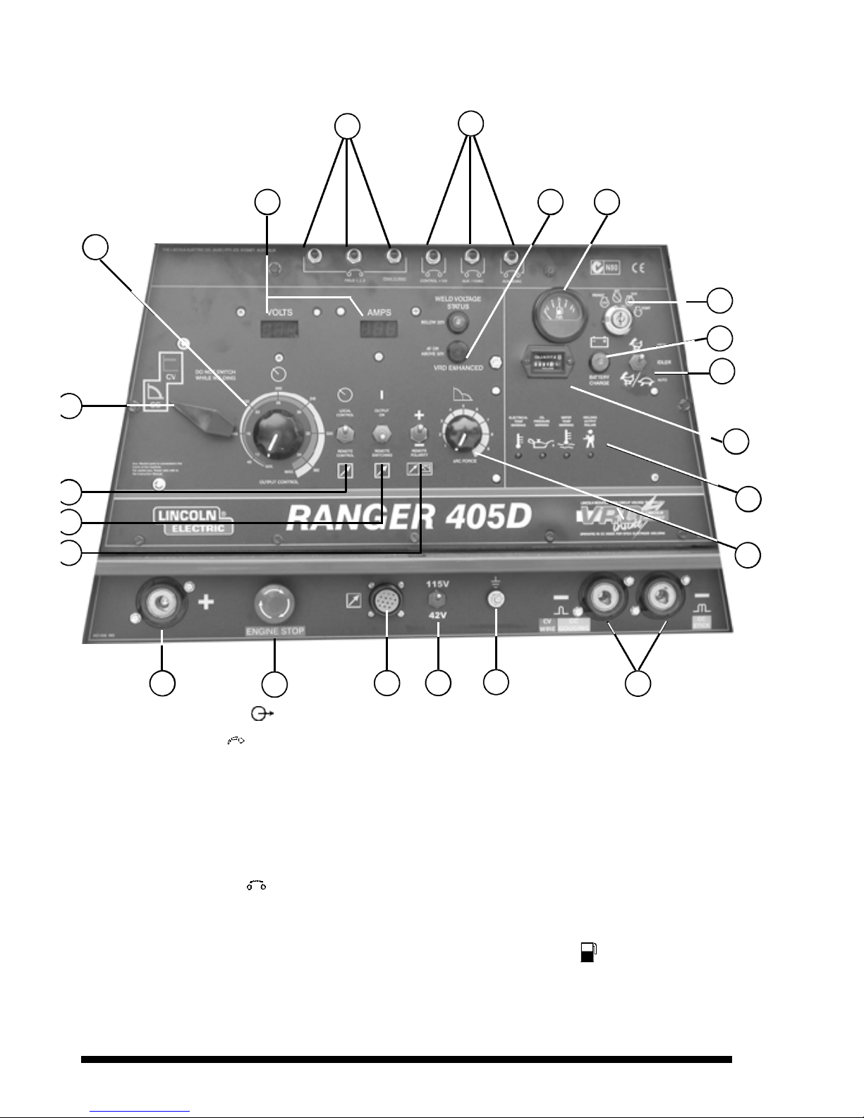
Controls and Settings
All welder and engine controls are located on the case front panel. Refer to diagram and the explanations that follow.
1
10
13
20
14
9
7
65
3
2
22
4
8
11
12
13
15
16
17
18
18
1. Output Control Dial
Increase/Decrease of output “ ” (Voltage or Current)
The output control on the control panel is a continuous control of
the machine output. The control may be rotated from minimum to
maximum while under load to adjust the machine output.
2. Volt-Amp Meter Module and Switch
Output stud voltage is displayed on the Volt Meter Module. Output
current Amps is displayed on the Amp Meter Module (where
fitted).
3 & 4. Circuit Breaker
Five circuit breakers are mounted on the top of the control panel.
If they are activated, press them to reset. Refer trouble shooting
guide if tripping occurs. Their functions are (left to right looking at
the control panel).
1, 2 & 3) Field winding protection
4) Control +12V
5) Auxiliary 115/42V
5. VRD Operation Indicator
On the front panel of the Ranger 405D are two indicator lights. A
red light when lit indicates voltage >32V and a green light when
lit indicates voltage <32V.
These lights monitor the OCV at all times. In the CC mode when
the welding arc has stopped the green light will aluminate
indicating that the VRD has reduced the OCV to less than 32V.
During welding the red light will aluminate indicating that the OCV
is greater than 32V. During welding the red and green light may
flicker on and off. This is normal operation as the welding voltage
depending on the process and type of the electrodes being used
may produce less than 32V.
Should the red light remain illuminated after stopping welding in
the CC mode. Please refer to your local field service shop for
service.
6. Fuel Level Gauge
Displays the level of diesel fuel in the fuel tank. The operator must
watch the fuel level closely to prevent running out of fuel and
possibly having to bleed the system.

7. Switch: PREHEAT STOP RUN START
Toggle to preheat position to energize the glow plugs, then toggle
through to the start position and hold to crank the engine; release
as the engine starts. To stop the engine, toggle to the stop
position.
Note: When starting the engine the engine stop button must be
released. If the engine stop button is used to stop the engine, the
key switch must also be toggled to the stop position otherwise the
battery may be drained.
8. Battery Charging Light
The yellow engine alternator light is off when battery charging
system is functioning normally. If light turns on the alternator or
the voltage regulator may not be operating correctly. The light will
remain on when the engine is stopped and the run/stop switch is
in the run position.
9. Idler Switch
Has two positions as follows:
A) In the “High” position , the engine runs at the high idle speed
controlled by the governor.
B) In the “Auto” position, the idler operates as follows:
a. When switched from “High” to “Auto” or after starting the
engine, the engine will operate at full speed for
approximately 12 seconds and then go to low idle speed.
b. When the electrode touches the work or power is drawn
for lights or tools (approximately 100 Watts minimum) the
engine accelerates and operates at full speed.
c. When welding ceases and the AC power load is turned
off, a fixed time delay of approximately 12 seconds
starts.
d. If the welding or AC power load is not restarted before
the end of the time delay, the idler reduces the engine
speed to low idle speed.
e. The engine will automatically return to high idle speed
when the welding load or A.C. power load is reapplied.
Idler Operational Exceptions
When the WELDING TERMINALS switch is in the “Remotely
Controlled” position the idler will operate as follows:
• When the triggering device (Amptrol, Arc Start Switch, etc.)
is pressed the engine will accelerate and operate at full
speed prov ided a weldin g loa d is applie d within
approximately 12 seconds.
• If the triggering device remains pressed but no welding load
is applied within approximately 12 seconds the engine will
return to low idle speed.
• If the triggering device is released or welding ceases the
engine will return to low idle speed after approximately 12
seconds.
10. Hour Meter
The hour meter displays the total time that the engine has been
running. This meter is a useful indicator for scheduling preventive
maintenance.
11. Engine Protection
The engine protection lights remain off with proper oil pressure
and under normal operating temperatures. If a light turns on the
engine protection system will stop the engine. the illuminated light
will indicate the reason for the engine shutdown. Low oil pressure,
high coolant temperature, high electrical temperature or electrical
fault.
Welder Thermal Protection Light
The thermal protection light will be lit if either of the two
electrical protection thermostats have opened. This circuit is
combined with the engine protection circuit so that if over
temperature is sensed the engine is shut down. The engine
will restart & run for only approx 10 seconds if the high temp
light is still illuminated.
Welding Output Failure
Incorrect voltages and / or welding output malfunction will cause
the Welding Output Failure light to be illuminated. The engine will
not restart and run if the “Welding Output Failure” light is still
illuminated.
Oil Pressure Light
This circuit is combined with the engine protection circuit so that
if low oil pressure is sensed the engine will shut down. The engine
will restart and run for approx 10 seconds if the low oil light is
illuminated.
12. Arc Force Control
(effective only in C.C. mode)
Increase/Decrease short circuit current
The arc force dial should be set at approx mid-range for most
welding. Adjustments up or down can then be made
depending on the electrode, procedures and operator
preference. Higher settings will provide more short circuit
current giving a more forceful arc. Excessive spatter may
result if the control setting is too high. For most TIG welding
applications adjust this control to minimum for best operating
characteristics.
13. Weld Output Terminals + and -
These Twistmate plugs and sockets provide welding connection
points for the electrode and work cables. For positive polarity
welding the electrode cable connects to the “+” terminal and the
work cable connects to this “-” terminal. For negative polarity
welding the work cable connects to the “+” terminal and the
electrode cable connects to this “-” terminal.
14. Earth Connection
An earthing stud is provided on the control panel. Refer to
Installation Instructions Section this manual. “Machine Earthing”
and local regulations eg. Australian Standard AS3000.
15. 42V / 115V Wire Feeder Voltage Switch
Toggles output of 14-pin connector to voltage requirement of Wire
Feeder.
16. Remote Control Receptacle
Amphenol Receptacle
The Ranger 405D has one 14pin amphenol located on the
control panel. The receptacle is for connecting wire feeders,
it allows the welder output to be controlled at the wire feeder,
when the wire feeder includes this feature, and includes
115V AC 5amp & 42V AC 10amp auxiliary supplies. These
supplies are protected by a circuit breaker mounted on the
control panel.
17. Engine Stop Button
When depressed stops and disables restarting of the engine by
removing the power supply to the engine injection pump solenoid.
18. Remote Polarity Switch
Remote Voltmeter
Positive Electrode
+
Negative Electrode
–
The remote voltmeter polarity switch allows the electrode polarity
to be set for the remote (No. 21) work sensing lead of automatic
or semi-automatic equipment. Set ‘+’ for electrode positive and ‘–’
for electrode negative.
19. Output Terminal Switch (output contactor)
(effective only in CV mode)
Output (Voltage) “ ”
ON “I”
Remote Switching “ ”
The output terminals toggle switch controls the solid state output
contactor. Switched to the “I” position the contactor is closed and
the output studs are “hot” all the time. Switched to the “ ”
position the output studs only become “hot” when wires No. 2 & 4
are shorted together using the wire feeder gun trigger.
20. Output Control “Local-Remote” Switch
Remote Output Voltage or Current Control “ ”
Local Output Voltage or Current Control “ ”
The Local/Remote switch, mounted beside the output control dial,
gives the operator the option of controlling the output at the
machine control panel or at a remote station. For control at the
machine, switch to “ ” position. For remote control, switch to “
” position, in this position control is at the wire feeder (if so
constructed) or at a K857 control connected to the amphenol on
the control panel. (See ‘Optional Field Installed Accessories’).
21.Weld Mode Selector Switch
Constant Voltage position is shown as “ ”, ‘CV’.
Constant Current position is shown as “ ”, ‘CC’.
Caution:- Never change the CV/CC switch setting while
welding. This will cause severe damage to the
switch and other electrical components.
There is no VRD protection in the CV mode.
With the toggle switch in the “WELD T E R M I N A L O N ”
position the voltage at the output terminal maybe up
to 60V.
W A R N I N G
INSTALLATION INSTRUCTIONS
 Loading...