

Page 1

TM
DD
Ranger 305D
For use with machines having Code Numbers: 10926, 11121, 11188, 11275 (Domestic)
11027, 11122, 11189, 11314 (UK)
11039, 11123, 11190, 11315 (EUROPE)
Safety Depends on You
Lincoln arc welding and cutting
equipment is designed and built
with safety in mind. However,
your overall safety can be increased by proper installation . . .
and thoughtful operation on
your part. DO NOT INSTALL,
OPERATE OR REPAIR THIS
EQUIPMENT WITHOUT
READING THIS MANUAL AND
THE SAFETY PRECAUTIONS
CONTAINED THROUGHOUT.
And, most importantly, think
before you act and be careful.
SVM175-A
July, 2007
SERVICE MANUAL
View Safety Info View Safety Info View Safety Info View Safety Info
Return to Master TOC Return to Master TOC Return to Master TOC Return to Master TOC
• Sales and Service through Subsidiaries and Distributors Worldwide •
Cleveland, Ohio 44117-1199 U.S.A. TEL: 1-888-935-3877 FAX: 216.486.1751 WEB SITE: www.lincolnelectric.com
• World's Leader in Welding and Cutting Products •
Copyright© 2007 Lincoln Global Inc.
Page 2
i
SAFETY
WARNING
CALIFORNIA PROPOSITION 65 WARNINGS
Diesel engine exhaust and some of its constituents
are known to the State of California to cause cancer, birth defects, and other reproductive harm.
The Above For Diesel Engines
ARC WELDING CAN BE HAZARDOUS. PROTECT YOURSELF AND OTHERS FROM POSSIBLE SERIOUS INJURY OR DEATH.
KEEP CHILDREN AWAY. PACEMAKER WEARERS SHOULD CONSULT WITH THEIR DOCTOR BEFORE OPERATING.
Read and understand the following safety highlights. For additional safety information, it is strongly recommended that you
purchase a copy of “Safety in Welding & Cutting - ANSI Standard Z49.1” from the American Welding Society, P.O. Box 351040,
Miami, Florida 33135 or CSA Standard W117.2-1974. A Free copy of “Arc Welding Safety” booklet E205 is available from the
Lincoln Electric Company, 22801 St. Clair Avenue, Cleveland, Ohio 44117-1199.
BE SURE THAT ALL INSTALLATION, OPERATION, MAINTENANCE AND REPAIR PROCEDURES ARE
PERFORMED ONLY BY QUALIFIED INDIVIDUALS.
The engine exhaust from this product contains
chemicals known to the State of California to cause
cancer, birth defects, or other reproductive harm.
The Above For Gasoline Engines
i
FOR ENGINE
powered equipment.
1.a. Turn the engine off before troubleshooting and maintenance
work unless the maintenance work requires it to be running.
____________________________________________________
1.b. Operate engines in open, well-ventilated
areas or vent the engine exhaust fumes
outdoors.
____________________________________________________
1.c. Do not add the fuel near an open flame welding arc or when the engine is running. Stop
the engine and allow it to cool before refueling to prevent spilled fuel from vaporizing on
contact with hot engine parts and igniting. Do
not spill fuel when filling tank. If fuel is spilled,
wipe it up and do not start engine until fumes
have been eliminated.
____________________________________________________
1.d. Keep all equipment safety guards, covers and devices in position and in good repair.Keep hands, hair, clothing and tools
away from V-belts, gears, fans and all other moving parts
when starting, operating or repairing equipment.
____________________________________________________
1.e. In some cases it may be necessary to remove safety
guards to perform required maintenance. Remove
guards only when necessary and replace them when the
maintenance requiring their removal is complete.
Always use the greatest care when working near moving
parts.
___________________________________________________
1.f. Do not put your hands near the engine fan.
Do not attempt to override the governor or
idler by pushing on the throttle control rods
while the engine is running.
1.h. To avoid scalding, do not remove the
radiator pressure cap when the engine is
hot.
ELECTRIC AND
MAGNETIC FIELDS
may be dangerous
2.a. Electric current flowing through any conductor causes
localized Electric and Magnetic Fields (EMF). Welding
current creates EMF fields around welding cables and
welding machines
2.b. EMF fields may interfere with some pacemakers, and
welders having a pacemaker should consult their physician
before welding.
2.c. Exposure to EMF fields in welding may have other health
effects which are now not known.
2.d. All welders should use the following procedures in order to
minimize exposure to EMF fields from the welding circuit:
2.d.1.
Route the electrode and work cables together - Secure
them with tape when possible.
2.d.2. Never coil the electrode lead around your body.
2.d.3. Do not place your body between the electrode and
work cables. If the electrode cable is on your right
side, the work cable should also be on your right side.
___________________________________________________
1.g. To prevent accidentally starting gasoline engines while
turning the engine or welding generator during maintenance
work, disconnect the spark plug wires, distributor cap or
magneto wire as appropriate.
Return to Master TOC Return to Master TOC Return to Master TOC Return to Master TOC
2.d.4. Connect the work cable to the workpiece as close as
possible to the area being welded.
2.d.5. Do not work next to welding power source.
Mar ʻ95
Page 3
ii
SAFETY
ii
ELECTRIC SHOCK can kill.
3.a. The electrode and work (or ground) circuits
are electrically “hot” when the welder is on.
Do not touch these “hot” parts with your bare
skin or wet clothing. Wear dry, hole-free
gloves to insulate hands.
3.b. Insulate yourself from work and ground using dry insulation.
Make certain the insulation is large enough to cover your full
area of physical contact with work and ground.
In addition to the normal safety precautions, if welding
must be performed under electrically hazardous
conditions (in damp locations or while wearing wet
clothing; on metal structures such as floors, gratings or
scaffolds; when in cramped positions such as sitting,
kneeling or lying, if there is a high risk of unavoidable or
accidental contact with the workpiece or ground) use
the following equipment:
• Semiautomatic DC Constant Voltage (Wire) Welder.
• DC Manual (Stick) Welder.
• AC Welder with Reduced Voltage Control.
3.c. In semiautomatic or automatic wire welding, the electrode,
electrode reel, welding head, nozzle or semiautomatic
welding gun are also electrically “hot”.
3.d. Always be sure the work cable makes a good electrical
connection with the metal being welded. The connection
should be as close as possible to the area being welded.
3.e. Ground the work or metal to be welded to a good electrical
(earth) ground.
3.f.
Maintain the electrode holder, work clamp, welding cable and
welding machine in good, safe operating condition. Replace
damaged insulation.
3.g. Never dip the electrode in water for cooling.
3.h. Never simultaneously touch electrically “hot” parts of
electrode holders connected to two welders because voltage
between the two can be the total of the open circuit voltage
of both welders.
3.i. When working above floor level, use a safety belt to protect
yourself from a fall should you get a shock.
3.j. Also see Items 6.c. and 8.
ARC RAYS can burn.
4.a. Use a shield with the proper filter and cover
plates to protect your eyes from sparks and
the rays of the arc when welding or observing
open arc welding. Headshield and filter lens
should conform to ANSI Z87. I standards.
4.b. Use suitable clothing made from durable flame-resistant
material to protect your skin and that of your helpers from
the arc rays.
4.c. Protect other nearby personnel with suitable, non-flammable
screening and/or warn them not to watch the arc nor expose
themselves to the arc rays or to hot spatter or metal.
FUMES AND GASES
can be dangerous.
5.a. Welding may produce fumes and gases
hazardous to health. Avoid breathing these
fumes and gases.When welding, keep
your head out of the fume. Use enough
ventilation and/or exhaust at the arc to keep
fumes and gases away from the breathing zone. When
welding with electrodes which require special
ventilation such as stainless or hard facing (see
instructions on container or MSDS) or on lead or
cadmium plated steel and other metals or coatings
which produce highly toxic fumes, keep exposure as
low as possible and below Threshold Limit Values (TLV)
using local exhaust or mechanical ventilation. In
confined spaces or in some circumstances, outdoors, a
respirator may be required. Additional precautions are
also required when welding on galvanized steel.
5. b. The operation of welding fume control equipment is affected
by various factors including proper use and positioning of the
equipment, maintenance of the equipment and the specific
welding procedure and application involved. Worker exposure level should be checked upon installation and periodically thereafter to be certain it is within applicable OSHA PEL
and ACGIH TLV limits.
5.c.
Do not weld in locations near chlorinated hydrocarbon
coming from degreasing, cleaning or spraying operations.
The heat and rays of the arc can react with solvent vapors
form phosgene, a highly toxic gas, and other irritating products.
5.d. Shielding gases used for arc welding can displace air and
cause injury or death. Always use enough ventilation,
especially in confined areas, to insure breathing air is safe.
vapors
to
Return to Master TOC Return to Master TOC Return to Master TOC Return to Master TOC
5.e. Read and understand the manufacturerʼs instructions for this
equipment and the consumables to be used, including the
material safety data sheet (MSDS) and follow your
employerʼs safety practices. MSDS forms are available from
your welding distributor or from the manufacturer.
5.f. Also see item 1.b.
AUG ʻ06
Page 4
iii
SAFETY
iii
WELDING SPARKS can
cause fire or explosion.
6.a.
Remove fire hazards from the welding area.
If this is not possible, cover them to prevent
the welding sparks from starting a fire.
materials from welding can easily go through small cracks
and openings to adjacent areas. Avoid welding near
hydraulic lines. Have a fire extinguisher readily available.
6.b. Where compressed gases are to be used at the job site,
special precautions should be used to prevent hazardous
situations. Refer to “Safety in Welding and Cutting” (ANSI
Standard Z49.1) and the operating information for the
equipment being used.
6.c. When not welding, make certain no part of the electrode
circuit is touching the work or ground. Accidental contact can
cause overheating and create a fire hazard.
6.d. Do not heat, cut or weld tanks, drums or containers until the
proper steps have been taken to insure that such procedures
will not cause flammable or toxic vapors from substances
inside. They can cause an explosion even
been “cleaned”. For information, purchase “Recommended
Safe Practices for the
Containers and Piping That Have Held Hazardous
Substances”, AWS F4.1 from the American Welding Society
(see address above).
6.e. Vent hollow castings or containers before heating, cutting or
welding. They may explode.
Sparks and spatter are thrown from the welding arc. Wear oil
6.f.
free protective garments such as leather gloves, heavy shirt,
cuffless trousers, high shoes and a cap over your hair. Wear
ear plugs when welding out of position or in confined places.
Always wear safety glasses with side shields when in a
welding area.
6.g. Connect the work cable to the work as close to the welding
area as practical. Work cables connected to the building
framework or other locations away from the welding area
increase the possibility of the welding current passing
through lifting chains, crane cables or other alternate circuits.
This can create fire hazards or overheat lifting chains or
cables until they fail.
6.h. Also see item 1.c.
Remember that welding sparks and hot
though
they have
Preparation
for Welding and Cutting of
CYLINDER may explode
if damaged.
7.a. Use only compressed gas cylinders
containing the correct shielding gas for the
process used and properly operating
regulators designed for the gas and
pressure used. All hoses, fittings, etc. should be suitable for
the application and maintained in good condition.
7.b. Always keep cylinders in an upright position securely
chained to an undercarriage or fixed support.
7.c. Cylinders should be located:
• Away from areas where they may be struck or subjected to
physical damage.
• A safe distance from arc welding or cutting operations and
any other source of heat, sparks, or flame.
7.d. Never allow the electrode, electrode holder or any other
electrically “hot” parts to touch a cylinder.
7.e. Keep your head and face away from the cylinder valve outlet
when opening the cylinder valve.
7.f. Valve protection caps should always be in place and hand
tight except when the cylinder is in use or connected for
use.
7.g. Read and follow the instructions on compressed gas
cylinders, associated equipment, and CGA publication P-l,
“Precautions for Safe Handling of Compressed Gases in
Cylinders,” available from the Compressed Gas Association
1235 Jefferson Davis Highway, Arlington, VA 22202.
FOR ELECTRICALLY
powered equipment.
8.a. Turn off input power using the disconnect
switch at the fuse box before working on
the equipment.
8.b. Install equipment in accordance with the U.S. National
Electrical Code, all local codes and the manufacturerʼs
recommendations.
8.c. Ground the equipment in accordance with the U.S. National
Electrical Code and the manufacturerʼs recommendations.
Return to Master TOC Return to Master TOC Return to Master TOC Return to Master TOC
Mar ʻ95
Page 5

iv
SAFETY
iv
PRÉCAUTIONS DE SÛRETÉ
Pour votre propre protection lire et observer toutes les instructions
et les précautions de sûreté specifiques qui parraissent dans ce
manuel aussi bien que les précautions de sûreté générales suivantes:
Sûreté Pour Soudage A LʼArc
1. Protegez-vous contre la secousse électrique:
a. Les circuits à lʼélectrode et à la piéce sont sous tension
quand la machine à souder est en marche. Eviter toujours
tout contact entre les parties sous tension et la peau nue
ou les vétements mouillés. Porter des gants secs et sans
trous pour isoler les mains.
b. Faire trés attention de bien sʼisoler de la masse quand on
soude dans des endroits humides, ou sur un plancher metallique ou des grilles metalliques, principalement dans
les positions assis ou couché pour lesquelles une grande
partie du corps peut être en contact avec la masse.
c. Maintenir le porte-électrode, la pince de masse, le câble de
soudage et la machine à souder en bon et sûr état defonctionnement.
d.Ne jamais plonger le porte-électrode dans lʼeau pour le
refroidir.
e. Ne jamais toucher simultanément les parties sous tension
des porte-électrodes connectés à deux machines à souder
parce que la tension entre les deux pinces peut être le total
de la tension à vide des deux machines.
f. Si on utilise la machine à souder comme une source de
courant pour soudage semi-automatique, ces precautions
pour le porte-électrode sʼapplicuent aussi au pistolet de
soudage.
zones où lʼon pique le laitier.
6. Eloigner les matériaux inflammables ou les recouvrir afin de
prévenir tout risque dʼincendie dû aux étincelles.
7. Quand on ne soude pas, poser la pince à une endroit isolé de
la masse. Un court-circuit accidental peut provoquer un
échauffement et un risque dʼincendie.
8. Sʼassurer que la masse est connectée le plus prés possible de
la zone de travail quʼil est pratique de le faire. Si on place la
masse sur la charpente de la construction ou dʼautres endroits
éloignés de la zone de travail, on augmente le risque de voir
passer le courant de soudage par les chaines de levage,
câbles de grue, ou autres circuits. Cela peut provoquer des
risques dʼincendie ou dʼechauffement des chaines et des
câbles jusquʼà ce quʼils se rompent.
9. Assurer une ventilation suffisante dans la zone de soudage.
Ceci est particuliérement important pour le soudage de tôles
galvanisées plombées, ou cadmiées ou tout autre métal qui
produit des fumeés toxiques.
10. Ne pas souder en présence de vapeurs de chlore provenant
dʼopérations de dégraissage, nettoyage ou pistolage. La
chaleur ou les rayons de lʼarc peuvent réagir avec les vapeurs
du solvant pour produire du phosgéne (gas fortement toxique)
ou autres produits irritants.
11. Pour obtenir de plus amples renseignements sur la sûreté, voir
le code “Code for safety in welding and cutting” CSA Standard
W 117.2-1974.
2. Dans le cas de travail au dessus du niveau du sol, se protéger
contre les chutes dans le cas ou on recoit un choc. Ne jamais
enrouler le câble-électrode autour de nʼimporte quelle partie du
corps.
3. Un coup dʼarc peut être plus sévère quʼun coup de soliel, donc:
a. Utiliser un bon masque avec un verre filtrant approprié ainsi
quʼun verre blanc afin de se protéger les yeux du rayonnement de lʼarc et des projections quand on soude ou
quand on regarde lʼarc.
b. Porter des vêtements convenables afin de protéger la peau
de soudeur et des aides contre le rayonnement de lʻarc.
c. Protéger lʼautre personnel travaillant à proximité au
soudage à lʼaide dʼécrans appropriés et non-inflammables.
4. Des gouttes de laitier en fusion sont émises de lʼarc de
soudage. Se protéger avec des vêtements de protection libres
de lʼhuile, tels que les gants en cuir, chemise épaisse, pantalons sans revers, et chaussures montantes.
5. Toujours porter des lunettes de sécurité dans la zone de
soudage. Utiliser des lunettes avec écrans lateraux dans les
PRÉCAUTIONS DE SÛRETÉ POUR
LES MACHINES À SOUDER À
TRANSFORMATEUR ET À
REDRESSEUR
1. Relier à la terre le chassis du poste conformement au code de
lʼélectricité et aux recommendations du fabricant. Le dispositif
de montage ou la piece à souder doit être branché à une
bonne mise à la terre.
2. Autant que possible, Iʼinstallation et lʼentretien du poste seront
effectués par un électricien qualifié.
3. Avant de faires des travaux à lʼinterieur de poste, la debrancher à lʼinterrupteur à la boite de fusibles.
4. Garder tous les couvercles et dispositifs de sûreté à leur place.
Return to Master TOC Return to Master TOC Return to Master TOC Return to Master TOC
Mar. ʻ93
Page 6

v v
MASTER TABLE OF CONTENTS FOR ALL SECTIONS
Page
Safety.................................................................................................................................................i-iv
Installation.............................................................................................................................Section A
Operation...............................................................................................................................Section B
Accessories ..........................................................................................................................Section C
Maintenance..........................................................................................................................Section D
Theory of Operation .............................................................................................................Section E
Troubleshooting and Repair ................................................................................................Section F
Electrical Diagrams ..............................................................................................................Section G
Parts Manuals.......................................................................................................(Code 10926) P-417
..........................................................................................(Code 11027, 11039) P-479
...............................................................................(Code 11121, 11188, 11275) P-492
............................................(Code 11122, 11123, 11189, 11190, 11314, 11315) P-494
RANGER 305D
Page 7

Section A-1 Section A-1
TABLE OF CONTENTS
- INSTALLATION SECTION -
Installation .............................................................................................................................Section A
Technical Specifications.......................................................................................................A-2, A-3
Safety Precautions ......................................................................................................................A-4
Location and Ventilation..............................................................................................................A-4
Storing ..................................................................................................................................A-4
Stacking ................................................................................................................................A-4
Angle of Operation................................................................................................................A-4
Lifting ....................................................................................................................................A-5
High Altitude Operation.........................................................................................................A-5
High Temperature Operation ................................................................................................A-5
Cold Weather Starting and Operation ..................................................................................A-5
Towing...................................................................................................................................A-5
Pre-Operation Engine Service ....................................................................................................A-6
Oil .........................................................................................................................................A-6
Fuel.......................................................................................................................................A-6
Engine Cooling System ........................................................................................................A-6
Battery Connections .............................................................................................................A-6
Muffler Outlet Pipe................................................................................................................A-6
Spark Arrester.......................................................................................................................A-6
High Frequency Generators for TIG Applications.................................................................A-6
Remote Control.....................................................................................................................A-7
Electrical Output Connections.....................................................................................................A-7
Machine Grounding ..............................................................................................................A-7
Welding Output Cables.........................................................................................................A-8
Cable Installation ............................................................................................................A-8
Auxiliary Power Receptacles ................................................................................................A-8
Standby Power Connections .......................................................................................A-8 - A-9
Connection of Ranger 305D to Premises Wiring......................................................................A-10
Return to Master TOC Return to Master TOC Return to Master TOC Return to Master TOC
RANGER 305D
Page 8
A-2 A-2
INSTALLATION
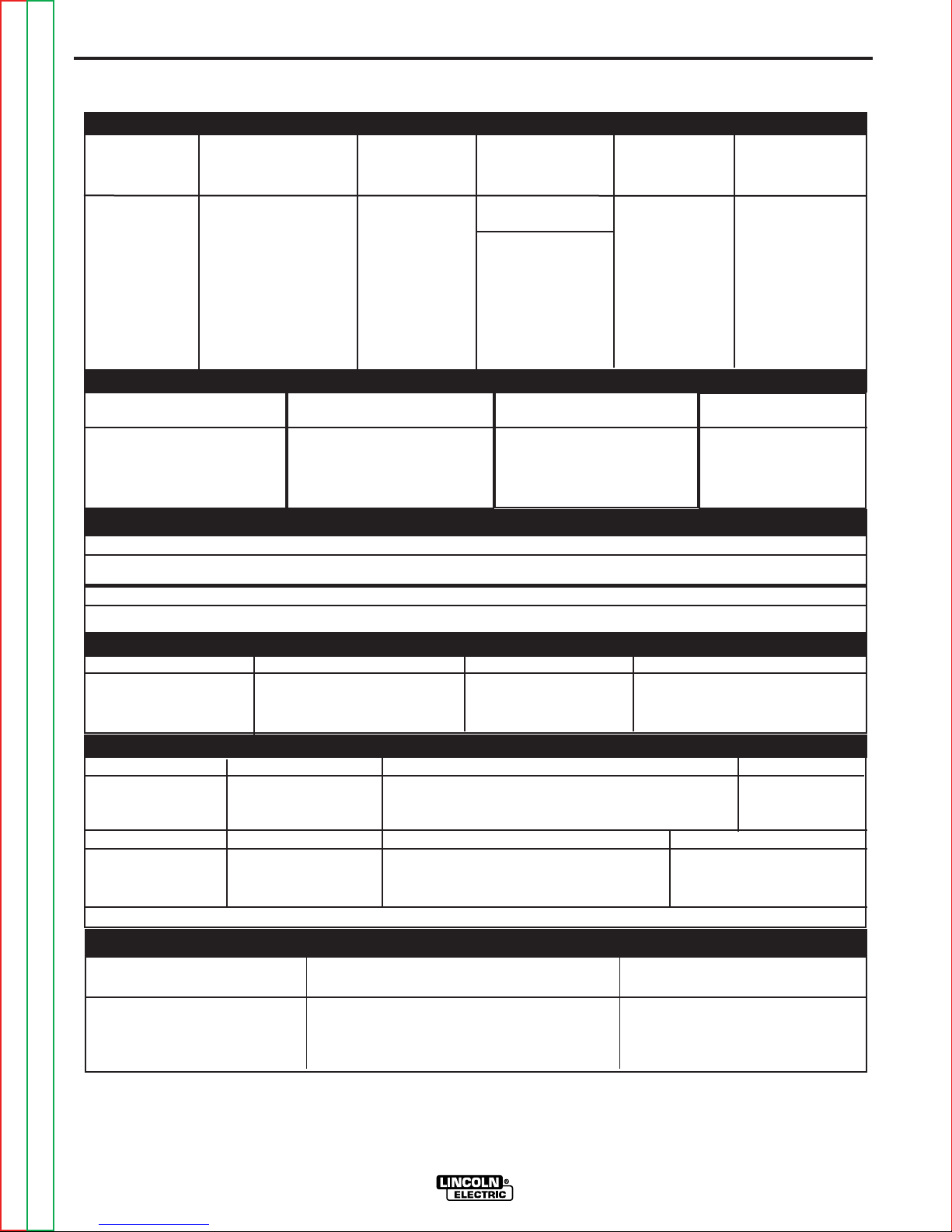
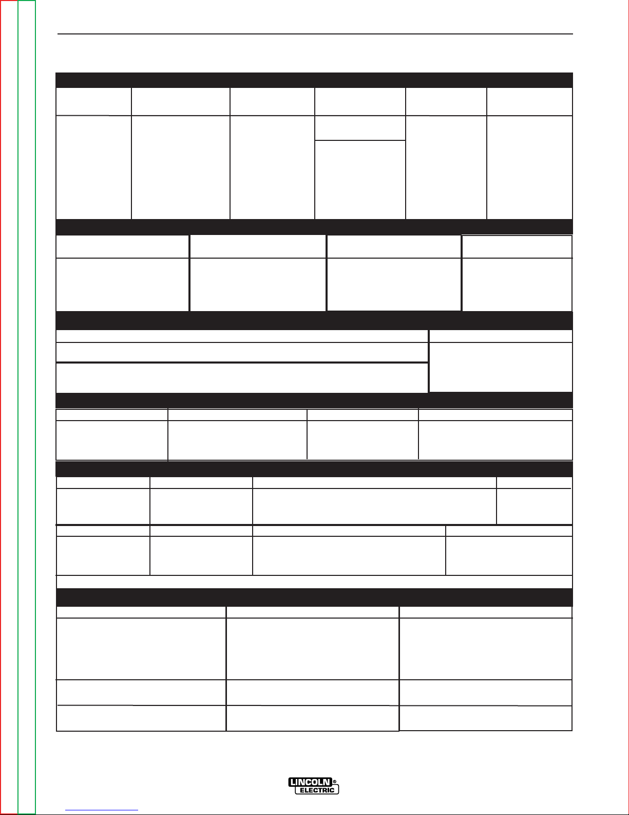
TECHNICAL SPECIFICATIONS - Ranger 305D (K1727-2) Code 10926, 11121, 11188, 11275
INPUT - DIESEL ENGINE
Make/Model Description Speed (RPM) Displacement Starting Capacities
cu. in. (cu. cm.) System
3 cylinder 43.88(789)
12VDC Battery &
Fuel: 12 gal.(45L)
4 stroke starter
18.8 HP High Idle 3650
Bore x Stroke inch (mm)
Oil: 3.4Qts. (3.2L)
Kubota** (14 KW)
D722 Net intermittent Full Load 3500
3600 RPM
2.64 x 2.68
(67 x 68 mm) cold crank amps) 3.85Qts. (3.6L)
(Group 58; 550 Radiator Coolant:
naturally aspirated Low Idle 2450 Battery Charger
water cooled engine
RATED OUTPUT @ 104° F (40° C) - WELDER
Welding Process
DC Constant Current
DC Pipe Current
Touch-Start™TIG
DC Constant Voltage
Welding Output
Current/Voltage/Duty Cycle
305A / 29V / 100%
300A / 29V / 100%
250A / 30V / 100%
300A / 29V / 100%
Output Range
20 TO 305 AMPS
40 TO 300 AMPS
20 TO 250 AMPS
14 TO 29 VOLTS
Max. Weld OCV
@Rated Load RPM
RATED OUTPUT @ 104° F (40° C).- GENERATOR
Auxiliary Power
10,000 Watts Peak, / 9,500 Watts Continuous, 60 Hz 120/240 Volts
Sound Levels
Sound Power: 104.2 dB Lwa, Sound Level: 80.6 dBA @ 23 ft ( 7m )
1
PHYSICAL DIMENSIONS
HEIGHT WIDTH DEPTH WEIGHT
30.00* in. 21.50 in 52.25 in.
762.0 mm 546.0 mm 1327.0 mm
698 lbs. (317kg.)
60 Volts
Return to Section TOC Return to Section TOC Return to Section TOC Return to Section TOC
ENGINE
LUBRICATION EMISSIONS FUEL SYSTEM GOVERNOR
Full Pressure
Electric Fuel Pump (Code 10926, 11121) or Mechanical Mechanical
with Full Flow Filter Certified to EPA Tier I Fuel Pump (Code 11188, 11275), Auto air bleed Governor
system Electric shutoff solenoid Indirect fuel injector
AIR CLEANER ENGINE IDLER MUFFLER ENGINE PROTECTION
Low noise Muffler: Shutdown on low oil
Single Element Automatic Idler Top outlet can be rotated. pressure & engine
Made from long life, aluminized steel. temperature
ENGINE WARRANTY: 2 year complete (parts and labor) 3rd. year major components (parts and labor)**
RECEPTACLES AND CIRCUIT BREAKERS
RECEPTACLES AUXILIARY POWER CIRCUIT BREAKER OTHER CIRCUIT BREAKERS
(2) 120VAC Duplex (5-20R) Two 20AMP for Two Duplex Receptacle
(1) 120/240VAC Dual Voltage Two 50AMP for Dual Voltage
Full KVA (14-50R)
1. Output rating in watts is equivalent to volt-amperes at unity power factor.
Output voltage is within ± 10% at all loads up to rated capacity. When
welding, available auxiliary power will be reduced.
Return to Master TOC Return to Master TOC Return to Master TOC Return to Master TOC
* Top of enclosure add 6 in. (152mm) for exhaust pipe.
** Engine warranty may vary outside of the USA. (See Engine warranty for
details)
RANGER 305D
25AMP for Battery Charging Circuit
15AMP for 42V Wire Feeder Power
Page 9
A-3 A-3
INSTALLATION
TECHNICAL SPECIFICATIONS - RANGER 305D (CE) K2279-1 (UK) Code 11027, 11122, 11189, 11314
& K2279-2 (EUROPE) Code 11039, 11123, 11190, 11315
INPUT - DIESEL ENGINE
Make/Model Description Speed (RPM) Displacement Starting Capacities
cu. in. (cu. cm.) System
3 cylinder 43.88(789)
12VDC Battery &
4 stroke starter 45L (12 US.gal.)
15.9 HP High Idle 3100
Kubota
(3)
(12 KW)
D722 Net intermittent Full Load 3000
Bore x Stroke inch (mm)
2.64 x 2.68
(Group 58; 550
3000 RPM (67 x 68 mm) cold crank amps) 3.6L(3.85 U Qts)
naturally aspirated Low Idle 2200 Battery Charge
water cooled engine
RATED OUTPUT @ 40° C (104° F) - WELDER
Welding Process
DC Constant Current
DC Pipe Current
Touch-Start™TIG
DC Constant Voltage
Welding Output
Current/Voltage/Duty Cycle
250A / 30V / 100%
250A / 30V / 100%
250A / 20V / 100%
250A / 27V / 100%
Output Range
20 TO 305 AMPS
40 TO 300 AMPS
20 TO 250 AMPS
14 TO 29 VOLTS
RATED OUTPUT @ 40° C (104° F) - GENERATOR
Auxiliary Power
8,500 Watts Peak, / 8,000 Watts Continuous, 50 Hz 115 & 230 Volts - 1 Phase
8,500 Watts Peak, / 8,000 Watts Continuous, 50 Hz 400 Volts - 3 Phase
(1)
Sound Power: 98 dB Lwa
PHYSICAL DIMENSIONS
HEIGHT WIDTH DEPTH WEIGHT
762mm 546mm 1524mm
30.0 in.
(2)
21.50 in. 60.0 in.
Fuel:
Oil:
3.2L(3.4 US. Qts.)
Radiator Coolant:
Max. Weld OCV
@Rated Load RPM
60 Volts
Sound Levels
341kg. (752lbs.)
LUBRICATION EMISSIONS FUEL SYSTEM GOVERNOR
Full Pressure
with Full Flow Filter Certified to EPA Tier I
AIR CLEANER ENGINE IDLER MUFFLER ENGINE PROTECTION
Single Element Automatic Idler Top outlet can be rotated. pressure & engine
ENGINE WARRANTY: 2 year complete (parts and labor) 3rd. year major components (parts and labor)
RECEPTACLES AND CIRCUIT BREAKERS
MODEL NUMBER
Receptacles
Residual Current Device (RCD)
Circuit Breakers (Thermal/Magnetic)
(1) Output rating in watts is equivalent to volt-amperes at unity power factor. Output
voltage is within ± 10% at all loads up to rated capacity. When welding, available auxiliary power will be reduced.
Return to Master TOC Return to Master TOC Return to Master TOC Return to Master TOC
Return to Section TOC Return to Section TOC Return to Section TOC Return to Section TOC
ENGINE
Electric Fuel Pump (Code 11027, 11039, 11122, 11123) or Mechanical
Fuel Pump (Code 11189, 11190, 11314, 11315), Auto air bleed
system Electric shutoff solenoid Indirect fuel injector
Low noise Muffler: Shutdown on low oil
Made from long life, aluminized steel. temperature
K2279-1 (UK)
400V (3 Ph) x 1
230V (1 Ph) x 1
115V x 1
(4)
14 Pin Connector
6 Pin Connector
4-pole, 25 Amp
(30mA trip current)
3 Phase, 20 Amp x 1
1 Phase, 15 Amp x 5
(2) To top of enclosure, add 152mm (6 “) to top of exhaust elbow.
(3) Engine warranty may vary outside of the USA. (See Engine warranty for details)
(4) Center-Tapped to ground.
RANGER 305D
K2279-2 (EUROPE)
400V (3 Ph) x 1
230V (1 Ph) x 2
14 Pin Connector
6 Pin Connector
4-pole, 25 Amp
(30mA trip current)
3 Phase, 20 Amp x 1
1 Phase, 15 Amp x 4
Mechanical
Governor
(3)
Page 10

A-4 A-4
INSTALLATION
Read this entire installation section before you
start installation.
STORING
SAFETY PRECAUTIONS
WARNING
Do not attempt to use this equipment until you have
thoroughly read the engine manufacturerʼs manual
supplied with your welder. It includes important safety
precautions, detailed engine starting, operating and
maintenance instructions and parts lists.
-----------------------------------------------------------------------
-ELECTRIC SHOCK can kill.
• Do not touch electrically live parts or
electrode with skin or wet clothing.
• Insulate yourself from work and ground
• Always wear dry insulating gloves.
-----------------------------------------------------------------------
ENGINE EXHAUST can kill.
• Use in open, well ventilated areas or
vent exhaust outside.
• Do not set anything near the engine.
-----------------------------------------------------------------------
MOVING PARTS can injure.
• Do not operate with doors open or
guards off.
• Stop engine before servicing.
• Keep away from moving parts.
----------------------------------------------------------------------
See additional safety information in the front of this
manual.
1. Store the machine in a cool, dry place when it is not
in use. Protect it from dust and dirt. Keep it where
it canʼt be accidentally damaged from construction
activities, moving vehicles, and other hazards.
2. If you will be storing the machine for over 30 days,
you should drain the coolant from the radiator.
Open the cock at the bottom of the radiator and
remove the pressure cap so that the coolant drains
completely. Attach a note that says “NO WATER”
on the radiator.
3. While the engine is still warm, drain the oil and refill
with fresh 10W30 oil. Change the oil filter. Run the
engine for about five minutes to circulate oil to all
the parts. See the Maintenance section for details
on changing oil.
4. Remove the battery, recharge it, and adjust the
electrolyte level. Store the battery in a dry, dark
place.
5. If the engine is not used for a long period of time,
every two or three months fill the radiator and run
the engine for about five minutes to keep it free
from rust.
Also see your engine Operatorʼs manual.
Fuel should also be drained when stored for long periods or a fuel additive should be used.
STACKING
Return to Section TOC Return to Section TOC Return to Section TOC Return to Section TOC
Only qualified personnel should install, use or service this equipment.
-----------------------------------------------------------------------
LOCATION AND VENTILATION
The welder should be located to provide an unrestricted flow of clean, cool air to the cooling air inlets and to
avoid restricting the cooling air outlets. Allow a minimum clearance of 2 feet (0.6m) from the case back
and 16in. (406mm) from either side of the base to a
vertical surface. Also, locate the welder so that the
engine exhaust fumes are properly vented to an outside area.
Return to Master TOC Return to Master TOC Return to Master TOC Return to Master TOC
Ranger 305D machines CANNOT be stacked.
ANGLE OF OPERATION
Engines are designed to run in the level of condition
which is where the optimum performance is achieved.
The maximum angle of continuous operation is 20
degrees in all directions. 30 degrees Intermittent (less
than 10 minutes continuous) in all directions. If the
engine is to be operated at an angle, provisions must
be made for checking and maintaining the oil level at
the normal (FULL) oil capacity in the crankcase.
When operating the welder at an angle, the effective
fuel capacity will be slightly less than the specified 12
gallons (45 ltrs.)
RANGER 305D
Page 11
A-5 A-5
INSTALLATION
LIFTING
The RANGER 305D weighs approximately 775lbs. (352kg.) with
a full tank of fuel (698 lbs. less fuel). A lift bail is mounted to the
machine and should always be used when lifting the machine
WARNING
• Lift only with equipment of adequate lifting capacity.
• Be sure machine is stable when
lifting.
• Do not lift this machine using lift
bail if it is equipped with a heavy
accessory such as trailer or gas
cylinder.
FALLING • Do not lift machine if lift bail is
EQUIPMENT can damaged.
cause injury. • Do not operate machine while
suspended from lift bail.
-------------------------------------------------------------------------------
HIGH ALTITUDE OPERATION
WARNING
DO NOT USE ETHER OR STARTING FLUID FOR
STARTING. SEVERE DAMAGE TO THE ENGINE
WILL RESULT.
------------------------------------------------------------------------
TOWING
The recommended trailer for use with this equipment for road, inplant and yard towing by a vehicle1is Lincolnʼs K957-1. (See
Accessories Section of this manual for trailer and trailer options).
If the user adapts a non-Lincoln trailer, he must assume responsibility that the method of attachment and usage does not result
in a safety hazard nor damage the welding equipment. Some of
the factors to be considered are as follows:
1. Design capacity of trailer vs. weight of Lincoln equipment and
likely additional attachments.
2. Proper support of, and attachment to, the base of the weld-
ing equipment so there will be no undue stress to the framework.
At higher altitudes, output derating may be necessary. For maximum rating, derate the machine 2.5% to 3.5% for every 1000 ft.
(305m). Due to new EPA and other local emissions regulations,
modifications to the engine for high altitude are restricted within
the United States and some European Countries. Use above
6000 ft.(1828 m) may be limited due to poor engine performance
or excessive exhaust smoke. An authorized Kubota engine field
service shop should be contacted to determine if any adjustments can be made for operation in higher elevations locally.
HIGH TEMPERATURE OPERATION
At temperatures above 104°F(40°C), Welder output derating is
necessary. For maximum output ratings, derate the welder output 2 volts for every 50°F(10°C) above 104°F(40°C).
Cold Weather Starting & Operation:
The Kubota engine used in the Ranger 305D can be
started in temperatures as low as 5°F (-15°C). At temperatures below 23°F (-5°C) it is recommended that
No. 1D diesel fuel is used in place of No. 2D. Allow
engine to warm up before applying a load or switching
to high idle. Lincoln Electric supplies a Cold Weather
Kit if the unit is to be used in Cold Weather Extremes
for long periods. See Field Installed options in the
Accessories section of this manual.
3. Proper placement of the equipment on the trailer to insure
stability side to side and front to back when being moved and
when standing by itself while being operated or serviced.
4. Typical conditions of use, i.e., travel speed; roughness of surface on which the trailer will be operated; environmental conditions; like maintenance.
5. Conformance with federal, state and local laws.
1
Consult applicable federal, state and local laws regarding specific requirements
for use on public highways.
1
VEHICLE MOUNTING
WARNING
Improperly mounted concentrated loads may
cause unstable vehicle handling and tires or other
components to fail.
• Only transport this Equipment on serviceable
vehicles which are rated and designed for such
loads.
• Distribute, balance and secure loads so vehicle
is stable under conditions of use.
• Do not exceed maximum rated loads for components such as suspension, axles and tires.
• Mount equipment base to metal bed or frame of
vehicle.
• Follow vehicle manufacturerʼs instructions.
------------------------------------------------------------------------
Return to Master TOC Return to Master TOC Return to Master TOC Return to Master TOC
Return to Section TOC Return to Section TOC Return to Section TOC Return to Section TOC
RANGER 305D
Page 12

A-6 A-6
INSTALLATION
PRE-OPERATION ENGINE SERVICE
READ the engine operating and maintenance instructions supplied with this machine.
WARNING
• Keep hands away from the engine muffler or HOT
engine parts.
• Stop the engine and allow it to cool before fueling.
• Do not smoke when fueling.
• Fill the tank at a moderate rate and do not overfill.
• Wipe up spilled fuel and allow the fumes to clear
before starting the engine.
• Keep sparks and flame away from the fuel tank.
• Remove the fuel cap slowly to release pressure.
------------------------------------------------------------------------
OIL
The RANGER 305D is shipped with the engine
crankcase filled with high quality SAE 10W-30 Oil that
meets classification CG-4 or CF-4 for
diesel engines. CHECK THE OIL LEVEL
BEFORE YOU START THE ENGINE. If it
is not up to the full mark on the dip stick,
add oil as required. Check the oil level every four hours
of running time during the first 50 running hours. Refer
to the engine Operatorʼs Manual for specific oil recommendations and break-in information. The oil change
interval is dependent on the quality of the oil and the
operating environment. Refer to the Engine Operatorʼs
Manual for more details on the proper service and
maintenance intervals.
FUEL
USE DIESEL FUEL ONLY
Fill the fuel tank with clean, fresh fuel. The
capacity of the fuel tank is 12 gallons (45.4
liters). When the fuel gauge reads empty
the tank contains approximately 2 gallons
(7.6 liters) of reserve fuel.
NOTE: Close the fuel shutoff valve located on the pre-
filter if not running the welder for extended periods.
ENGINE COOLING SYSTEM
WARNING
HOT COOLANT can burn skin.
•Do not remove cap if radiator is hot.
•The engine and radiator or this machine are filled with
a 50% mixture of ethylene-glycol based permanent
type antifreeze. See the Maintenance section and
the engine Operationʼs Manual for more information.
BATTERY CONNECTION
WARNING
BATTERY ACID CAN BURN EYES AND SKIN.
•Wear gloves and eye protection and be
careful when working near a battery.
Follow the instructions printed on the battery.
•Use caution as the electrolyte is strong
acid that can burn skin and damage eyes.
------------------------------------------------------------------------
The RANGER 305D is shipped with the negative battery cable disconnected. Make certain that the RUNSTOP switch is in the STOP position. Access the negative post of the battery by opening the left side engine
cover. Attach the negative battery cable to the negative
battery terminal and tighten using a socket or wrench.
NOTE: This machine is furnished with a wet charged
battery; if unused for several months, the battery may
require a booster charge. Be careful to charge the battery with the correct polarity. See battery charging
instructions in the Maintenance section.
MUFFLER OUTLET PIPE
Using the clamp provided secure the outlet pipe to the
outlet tube with the pipe positioned to direct the
exhaust in the desired direction. Tighten using a socket or wrench.
SPARK ARRESTER
Some federal, state or local laws may require that
gasoline or diesel engines be equipped with exhaust
spark arresters when they are operated in certain locations where unarrested sparks may present a fire hazard. The standard muffler included with this welder
does not qualify as a spark arrester. When required by
local regulations, a suitable spark arrester must be
installed and properly maintained. See the
Accessories section for more information.
CAUTION
An incorrect spark arrestor may lead to damage to the
engine or adversely affect performance.
------------------------------------------------------------------------
HIGH FREQUENCY GENERATORS FOR
TIG APPLICATIONS.
The K930-2 TIG Module is suitable for use with the
Ranger 305D. The Ranger 305D and any high frequency generating equipment must be properly
grounded. See the K930-2 operating manual for complete instructions on installation, operation, and maintenance.
Return to Master TOC Return to Master TOC Return to Master TOC Return to Master TOC
Return to Section TOC Return to Section TOC Return to Section TOC Return to Section TOC
RANGER 305D
Page 13
A-7 A-7
1
4
2
Note: Output stud covers not shown.
Code 11275 and above
3
INSTALLATION
REMOTE CONTROL
The RANGER 305D is equipped with both a 6-pin and
a 14-pin Amphenol connector. The 6-pin connector is
primarily used to connect a remote control device, such
as a K857, or a TIG Amptrol, such as the K870 or
K812. The 14-pin Amphenol connector is primarily
used to directly connect a wire feeder, TIG module, or
Spool Gun module control cable. See Accessories
section for more information.
NOTE: Both the 6-pin and 14-pin Amphenols share the
same output control auto-sensing and contactor circuitry; for this reason, there can only be one device
plugged into the Ranger 305D at any time.
Switch operation is covered in “Operation” section.
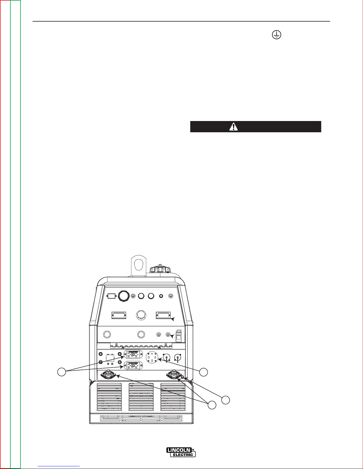
ELECTRICAL OUTPUT CONNECTIONS
See Figure A.1 for the location of the 120 and 240 volt
receptacles, weld output terminals, and ground stud.
Output stud covers are provided on code 11275 and
above.
MACHINE GROUNDING
Because this portable engine driven welder creates its
own power, it is not necessary to connect its frame to
an earth ground, unless the machine is connected to
premises wiring (home, shop, etc.)
To prevent dangerous electric shock, other equipment
to which this engine driven welder supplies power
must:
• Be grounded to the frame of the welder using a
grounded type plug or be double insulated.
WARNING
Do not ground this machine to a pipe that carries explosive or combustible material.
When this welder is mounted on a truck or trailer, its
frame must be electrically bonded to the metal frame of
the vehicle. Use a #8 or larger copper wire connected
between the machine grounding stud and the frame of
the vehicle. When this engine driven welder is connected to premises wiring such as that in a home or
shop, its frame must be connected to the system earth
ground. See further connection instructions in the section entitled "Standby Power Connections" as well as
the article on grounding in the latest National Electrical
Code and the local code.
Figure A.1 - RANGER 305D OUTPUT CONNECTIONS
Note: Different models appearance
may vary slightly.
Return to Master TOC Return to Master TOC Return to Master TOC Return to Master TOC
Return to Section TOC Return to Section TOC Return to Section TOC Return to Section TOC
RANGER 305D
Page 14

A-8 A-8
INSTALLATION
In general, if the machine is to be grounded, it should
be connected with a #8 or larger copper wire to a solid
earth ground such as a metal water pipe going into the
ground for at least ten feet and having no insulated
joints, or to the metal framework of a building which has
been effectively grounded. The National Electrical
Code lists a number of alternate means of grounding
electrical equipment. A machine grounding stud
marked with the ground symbol is provided on the
front of the welder.
WELDING OUTPUT CABLES
With the engine off connect the electrode and work
cables to the output terminals. The welding process
dictates the polarity of the electrode cable. These connections should be checked periodically and tightened
with a wrench.
Table A.1 lists recommended cable sizes and lengths
for rated current and duty cycle. Length refers to the
distance from the welder to the work and back to the
welder. Cable diameters are increased for long cable
lengths to reduce voltage drops. Long lengths of cable
should not be left coiled when welding.
CABLE INSTALLATION TABLE A.1
TOTAL COMBINED LENGTH OF
ELECTRODE AND WORK CABLES
Cable Length
0-100Ft. (0-30 meters)
100-150 Ft. (30-46 meters)
Cable Size for
305 Amps
100% Duty Cycle
1 / 0 AWG
2 / 0 AWG
NOTE: Long lengths of welding cable should not
remain coiled or wrapped while welding.
CAUTION
• Loose connections will cause the output terminals to
overheat. The terminals may eventually melt.
• Do not cross the welding cables at the output terminal connection. Keep the cables isolated and separate from one another.
-----------------------------------------------------------
AUXILIARY POWER RECEPTACLES
The auxiliary power of the RANGER 305D consists of
two 20 Amp-120 VAC (5-20R) duplex receptacles with
GFCI protection and one 50 Amp 120/240 VAC (1450R) receptacle. The 240 VAC receptacle can be split
for single phase 120 VAC operation.
The auxiliary power capacity is 10,000 watts Peak,
9,500 Watts Continuous of 60 Hz, single phase power.
The auxiliary power capacity rating in watts is equivalent to volt-amperes at unity power factor. The max
permissible current of the 240 VAC output is 42 amps.
The 240 VAC output can be split to provide two separate 120 VAC outputs with a max permissible current
of 42 Amps per output to two separate 120 VAC
branch circuits (these circuits cannot be paralleled).
Output voltage is within ± 10% at all loads up to rated
capacity. Auxiliary power is protected by circuit breakers.
The 120 V auxiliary power receptacles should only be
used with three wire grounded type plugs or approved
double insulated tools with two wire plugs. The current
rating of any plug used with the system must be at
least equal to the current capacity of the associated
receptacle.
Return to Section TOC Return to Section TOC Return to Section TOC Return to Section TOC
150-200 Ft. (46-61 meters)
Install the welding cables to your RANGER 305D as
follows.
1. The engine must be OFF to install welding cables.
2. Remove the flanged nuts from the output terminals.
3. Connect the electrode and work cables to the weld
output terminals. The terminals are identified on the
case front.
4. Tighten the flanged nuts securely.
5. Be certain that the metal piece you are welding (the
“work”) is properly connected to the work clamp and
cable.
6. Check and tighten the connections periodically.
Return to Master TOC Return to Master TOC Return to Master TOC Return to Master TOC
3 / 0 AWG
NOTE: The 240 V receptacle has two 120 V circuits,
but are of opposite polarities and cannot be paralleled.
STANDBY POWER CONNECTIONS
The RANGER 305D is suitable for temporary, standby
or emergency power using the engine manufacturerʼs
recommended maintenance schedule.
The RANGER 305D can be permanently installed as
a standby power unit for 240 VAC, 3 wire, single
phase, 50 amp service. Connections must be made by
a licensed electrician who can determine how the
120/240 VAC power can be adapted to the particular
installation and comply with all applicable electrical
codes.The following information can be used as a
guide by the electrician for most applications. Refer to
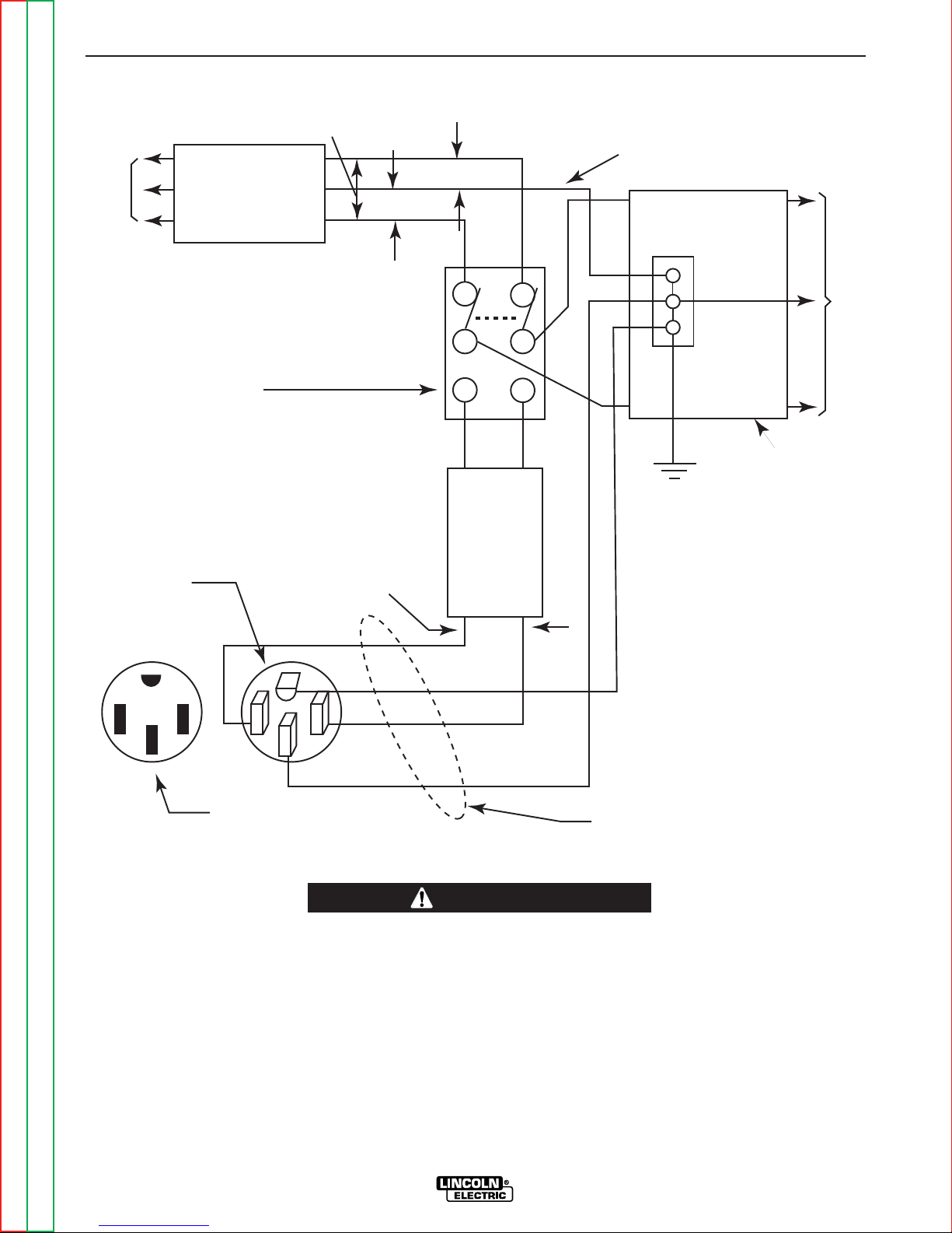
the connection diagram in Figure A.2.
RANGER 305D
Page 15

A-9 A-9
INSTALLATION
1. Install the double-pole, double-throw switch
between the power company meter and the premises disconnect. Switch rating must be the same or
greater than the customerʼs premises disconnect
and service over-current protection.
3. Install a 50 amp, 120/240 VAC plug (NEMA Type
14-50 to the double-pole circuit breaker using No.
6, 4-conductor cable of the desired length. (The 50
amp, 120/240 VAC plug is available in the optional
K802R plug kit or as part number T12153-9.
2. Take necessary steps to assure load is limited to
the capacity of the Ranger 305D by installing a 50
amp, 240 VAC double-pole circuit breaker.
Maximum continuous rated load for each leg of the
240 VAC auxiliary is 40 amperes. Loading above
the rated output will reduce output voltage below
the allowable +/- 10% of rated voltage, which may
damage appliances or other motor-driven equipment and may result in overheating of the Ranger
305D engine and/or alternator windings.
4. Plug this cable into th 50 amp, 120/240 VAC receptacle on the Ranger 305D case front.
Return to Master TOC Return to Master TOC Return to Master TOC Return to Master TOC
Return to Section TOC Return to Section TOC Return to Section TOC Return to Section TOC
RANGER 305D
Page 16
A-10 A-10
240 Volt
60 Hz.
3-Wire
Service
POWER
COMPANY
METER
240 VOLT
120 VOLT
120 VOLT
LOAD
N
NEUTRAL
BUS
GROUND
PREMISES
DISCONNECT AND
SERVICE
OVERCURRENT
PROTECTION
GND
N
NOTE: No. 6 COPPER CONDUCTOR CABLE SEE
NATIONAL ELECTRICALCODE FOR ALTERNATE WIRE
SIZE RECOMMENDATIONS.
240 VOLT
GROUNDED CONDUCTOR
50AMP
240 VOLT
DOUBLE
POLE
CIRCUIT
BREAKER
DOUBLE POLEDOUBLE THROW
SWITCH RATINGTO BE THE SAME
AS ORGREATER THAN PREMISES
SERVICE OVERCURRENT
PROTECTION.
50 AMP,120/240
VOLT PLUG
NEMA TYPE14-50
50 AMP,120/240 VOLT
RECEPTACLE
INSTALLATION
FIGURE A.2 CONNECTION OF RANGER 305D TO PREMISES WIRING
WARNING
• Only a licensed, certified, trained electrician should install the machine to a premises or residential electrical system. Be certain that:
• The installation complies with the National Electrical Code and all other applicable electrical codes.
• The premises is isolated and no feedback into the utility system can occur. Certain state and local
laws require the premises to be isolated before the generator is linked to the premises. Check your state
and local requirements.
• A double pole, double throw transfer switch in conjunction with the properly rated double-pole/ double
throw circuit breaker is connected between the generator power and the utility meter.
Return to Master TOC Return to Master TOC Return to Master TOC Return to Master TOC
Return to Section TOC Return to Section TOC Return to Section TOC Return to Section TOC
RANGER 305D
Page 17

Section B-1 Section B-1
TABLE OF CONTENTS
- OPERATION SECTION -
Operation...............................................................................................................................Section B
Operating Instructions .................................................................................................................B-2
Safety Instructions.......................................................................................................................B-2
General Description ....................................................................................................................B-2
Design Features ..........................................................................................................................B-3
Controls and Settings..................................................................................................................B-3
Engine Controls ....................................................................................................................B-4
Welding Controls ..................................................................................................................B-5
Engine Operation ........................................................................................................................B-6
Before Starting the Engine ...................................................................................................B-6
Starting the Engine...............................................................................................................B-6
Stopping the Engine .............................................................................................................B-6
Stick Welding ..............................................................................................................................B-7
Constant Current (CC-Stick) Welding.............................................................................B-7
Pipe Welding...................................................................................................................B-7
TIG Welding..........................................................................................................................B-8
Wire Welding-CV ..................................................................................................................B-8
Arc Gouging..........................................................................................................................B-8
Auxiliary Power ...........................................................................................................................B-8
Simultaneous Welding and Auxiliary Power Loads ..............................................................B-9
Return to Master TOC Return to Master TOC Return to Master TOC Return to Master TOC
RANGER 305D
Page 18
B-2 B-2
OPERATION
OPERATING INSTRUCTIONS
WARNING
Read and understand this entire section before operating your Ranger 305D.
SAFETY INSTRUCTIONS
WARNING
ENGINE EXHAUST can kill.
• Use in open, well ventilated areas or
vent exhaust to the outside.
• Do not stack anything on or near the
engine.
Do not attempt to use this equipment until you have
thoroughly read all the operating and maintenance
manuals supplied with your machine. They include
important safety precautions; detailed engine starting,
operating and maintenance instructions and parts lists.
------------------------------------------------------------------------
ELECTRIC SHOCK can kill.
• Do not touch electrically live parts such
as output terminals or internal wiring.
• Insulate yourself from work and
ground.
• Always wear dry insulating gloves.
------------------------------------------------------------------------
FUMES AND GASES can be dangerous.
• Keep your head out of fumes.
• Use ventilation or exhaust to remove
fumes from breathing zone.
------------------------------------------------------------------------
WELDING SPARKS can cause fire or
explosion.
• Keep flammable material away.
• Do not weld on containers that have
held combustibles.
------------------------------------------------------------------------
ARC RAYS can burn.
------------------------------------------------------------------------
MOVING PARTS can injure.
• Do not operate this equipment with any
of its doors open or guards off.
• Stop the engine before servicing it.
• Keep away from moving parts.
------------------------------------------------------------------------
Only qualified personnel should install, use, or ser-
vice this equipment.
------------------------------------------------------------------------
ADDITIONAL SAFETY
PRECAUTIONS
Always operate the welder with the hinged door closed
and the side panels in place. These provide maximum
protection from moving parts and insure proper cooling
air flow.
GENERAL DESCRIPTION
The Ranger 305D is a diesel-engine-powered DC
multi-process welding power source and 120 / 240
VAC power generator. The engine drives a generator
that supplies three-phase power for the DC welding circuit and single-phase power for the AC auxiliary outlets. The DC welding control system uses state of the
art Chopper Technology (CT
performance.
TM
) for superior welding
• Wear eye, ear, and body protection.
Return to Master TOC Return to Master TOC Return to Master TOC Return to Master TOC
Return to Section TOC Return to Section TOC Return to Section TOC Return to Section TOC
RANGER 305D
Page 19

B-3 B-3
OPERATION
DESIGN FEATURES
• Single, full-range output control dial.
• 4 welding modes: CC-stick, downhill stick welding on
pipe, CV wire welding and Touch-Start TIGTM(eliminates high frequency and tungsten contamination).
• Output at welding terminals controlled by electronic
contactor. Can be switched to “On”, or to “Remotely
Controlled”.
• Many wire feeder combinations: 14-pin connector for
Lincoln wire feeders LN-25, LN-23P, LN-7, LN-8 operates when using a Lincoln wire feeder with the appropriate control cable.
• Smart machine! Remote operation and Magnum
spool gun; 42VAC for LN-742 and Cobramatic®wire
feeders.
• 12 gallon fuel capacity allows you to run an extended
day.
• Easily check fuel level during operation and refuelling
with highly visuable fuel gauge.
Some models have gauge located next to fuel cap on
case top.
• Longer engine life, reduced noise emissions and
great fuel economy with the automatic engine idler.
• Conveniently located engine maintenance label under
top engine door.
• Engine hour meter for scheduled maintenance.
• Electric start.
• Oil drain valve (no tools required).
• See spec pages for watts of continuous duty AC generator power.
®
• See spec pages for Amp and voltages output specs.
Circuit breaker protection.
• See spec pages for receptacle information.
CONTROL AND SETTINGS
The diesel engine stop/start and idler controls are
located on the case front panel. The welder controls
are also located here. See Figure B.1.
Some models have gauge located on front panel.
• Voltmeter and ammeter display actual volts and amps
at output terminals when welding.
Return to Master TOC Return to Master TOC Return to Master TOC Return to Master TOC
Return to Section TOC Return to Section TOC Return to Section TOC Return to Section TOC
RANGER 305D
Page 20

B-4 B-4
6
5
1
9
10
11
4
7
3
2
16
15
14
13
12
8
NOTE: Layout and appearance
vary between models.
OPERATION
FIGURE B.1
ENGINE CONTROLS (Figure B.1)
1. RUN.STOP SWITCH:
the engine prior to starting. STOP position stops
the engine.
RUN position energizes
2. GLOW PLUG PUSH BUTTON: When
pressed, this button activates the engine glow
plugs to preheat the engine for starting. This button also temporarily powers the fuel solenoid hold
coil. On codes 10926 and 11121, the electric fuel
pump is also temporarily activated.
3. START PUSH BUTTON: Energizes the
starter to crank the engine and activates the fuel
solenoid pull coil.
A) In the HIGH position, the engine runs at the high idle
speed controlled by the engine governor.
B) In the AUTO position, the idler operates as follows:
a. When switched from HIGH to AUTO or after starting the
engine, the engine will operate at high speed for approximately 12 seconds and then go to low idle speed.
b. When the electrode touches the work or power is drawn
from the auxiliary power receptacles (approximately 100
watts minimum, the engine accelerates and operates at
high speed.
c. When welding ceases or the AC power load is turned off,
a fixed time delay of approximately 12 seconds starts. If
the welding or AC power load is not restarted before the
end of the time delay, the idler reduces the engine RPM to
low idle speed.
d. The engine will automatically return to high idle speed
when the welding load or AC power load is reapplied.
4.
ENGINE ALTERNATOR TROUBLE LIGHT:
The yellow engine alternator light is off when the
battery charging system is functioning normally. If
the light turns on, the alternator or the voltage regulator may not be operating correctly. The light may
also come on if the battery is not holding a charge.
It is normal for the light to come on while starting
the engine. (Code 10926 and over)
5. ELECTRIC FUEL GAUGE: (Codes 11121
and higher) gives accurate and reliable indication
as to how much fuel is in the fuel tank.
6. ENGINE HOUR METER: Displays the total
time that the engine has been running. This meter
is useful for scheduling prescribed maintenance.
7. ENGINE PROTECTION LIGHT: A warning indicator
light for low oil pressure and/or coolant over temperature.
The light is off when the systems are functioning properly.
The light turns on then the RUN/STOP switch is in the “ON”
position before starting the engine. If the Engine Protection
or Battery Charging lights do NOT turn off shortly after starting the engine, stop the engine immediately and determine
the cause.
8. IDLER SWITCH: Has two positions as follows:
1) In the HIGH position, the engine runs at the high idle
speed controlled by the engine governor.
2) In the AUTO position, the idler operates as follows:
• When switched from HIGH to AUTO or after starting
the engine, the engine will operate at full speed for
approximately 12 seconds and then go to low idle
speed.
Return to Master TOC Return to Master TOC Return to Master TOC Return to Master TOC
Return to Section TOC Return to Section TOC Return to Section TOC Return to Section TOC
RANGER 305D
Page 21

B-5 B-5
OPERATION
• When the electrode touches the work or power is
drawn for lights or tools (approximately 100 Watts
minimum), the engine accelerates and operates at
full speed.
• When welding ceases or the AC power load is
turned off, a fixed time delay of approximately 12
seconds starts. If the welding or AC power load is
not restarted before the end of the time delay, the
idler reduces the engine speed to low idle speed.
• The engine will automatically return to high idle
speed when there is welding load or AC power load
reapplied.
CV-WIRE mode: In this mode, turning the ARC CONTROL
clock wise from –10 (soft) to +10 (crisp) changes the arc
from soft and washed-in to crisp and narrow. It acts as an
inductance/pinch control. The proper setting depends on the
procedure and operator preference. Start with a setting of 0.
12. 14-PIN AMPHENOL: Primarily used for attaching
accessories, such as a wire feeder, spool gun module or
TIG module. It provides connections to both 120VAC and
42VAC power, and to the weld circuit work voltage sensing
lead. It also provides a connection to the same control circuits described in the 6-PIN AMPHENOL section below.
WELDING CONTROLS
9. OUTPUT CONTROL: The output control dial is used
to present the output voltage or current as displayed on
the digital meters for each of the four welding modes. It
can also be used to vary the output while welding. This
control is disabled by an auto-sensing circuit if the
machine is in CC-Stick, Downhill pipe, or CV-wire modes,
and an accessory device with output control capability is
plugged into either amphenol.
When in Touch-Start TIG mode, and when an accessory
device with output control, such as an Amptrol, is plugged
in to either Amphenol, the OUTPUT control dial is used to
set the maximum current range of the accessory output
control device.
10. WELD MODE SELECTOR SWITCH: This switch
provides four selectable welding modes:
- CV-WIRE
- DOWNHILL PIPE
- CC-STICK
- TOUCH STARTING
11. ARC CONTROL- The ARC CONTROL dial is active
in the CV-WIRE, CC-STICK, and DOWNHILL PIPE
modes, and has different functions in these modes. This
control is not active in the TOUCH START TIG mode.
CC-STICK mode: In this mode, the ARC CONTROL dial
sets the short circuit current (arc-force) during stick welding to adjust for a soft or crisp arc. Increasing the dial from
–10 (soft) to +10 (crisp) increases the short circuit current
and prevents sticking of the electrode to the plate while
welding. This can also increase spatter. It is recommended that the ARC CONTROL be set to the minimum number without electrode sticking. Start with a setting at 0.
13. 6-PIN AMPHENOL- Primarily used to connect a
remote control device, such as the K857, or a TIG Amptrol,
such as the K870 or K812.
Both the 6 and 14-Pin amphenols are connected to a
remote control auto-sensing circuit that transfers all or partial output control functions from the front panel output control dial to the remote output control device.
When in TOUCH START TIG mode, a remote output control device will vary the output from MIN up to the value set
with the front panel output control dial. In all other modes,
the front panel output control is completely disabled, and
full MIN to MAX control is transferred to the remote output
control device.
Both Amphenols also connect to an electronic output contactor circuit. When the “Weld Terminals” switch is in the
“remotely controlled” position, the weld terminals are
switched on an doff by the device connected to either
amphenol.
NOTE: Both the 6 pin and 14 pin Amphenols share the same
output control auto-sensing and contactor circuitry; for
this reason, there can only be one device plugged into
the Ranger 305D at any time.
14. WELD TERMINALS CONTROL SWITCH- In the
WELD TERMINALS ON position, the output is electrically
hot all the time. In the REMOTELY CONTROLLED position, the output is controlled by a wire feeder or amptrol
device, and is electrically off until a remote switch is
closed.
15. WIRE FEEDER VOLTMETER SWITCH:
Matches the polarity of the wire feeder voltmeter to
the polarity of the electrode.
DOWNHILL PIPE mode: In this mode, the ARC CONTROL dial sets the short circuit current (arc-force) during
stick welding to adjust for a soft or a more forceful digging
arc (crisp). Increasing the number from –10 (soft) to +10
(crisp) increases the short circuit current which results in a
more forceful digging arc. Typically a forceful digging arc
is preferred for root and hot passes. A softer arc is preferred for fill and cap passes where weld puddle control
and deposition ("stacking" of iron) are key to fast travel
speeds. It is recommended that the ARC CONTROL be
set initially at 0.
Return to Master TOC Return to Master TOC Return to Master TOC Return to Master TOC
Return to Section TOC Return to Section TOC Return to Section TOC Return to Section TOC
16. DIGITAL OUTPUT METERS:
The digital meters allow the output voltage (“CVWIRE” mode) or current (“CC-STICK”, “DOWNHILL
PIPE” and “TOUCH START TIG” modes) to be preset
prior to welding using the output control dial. When
pre-setting voltage the AMPS display will be off and
while pre-setting amps, the VOLTS display will be off.
While welding, the machine display both the actual
voltage (VOLTS) and current (AMPS).
RANGER 305D
Page 22
B-6 B-6
OPERATION
ENGINE OPERATION
WARNING
DO NOT RUN THE ENGINE AT EXCESSIVE
SPEEDS. The maximum allowable high idle speed for
the Ranger 305D is 3650 RPM, no load. Do NOT
adjust the governor screw on the engine.
Severe personal injury and damage to the machine
can result if it is operated at speeds above the maximum rated speed.
Read and understand all safety instructions included in
the engine operatorʼs manual that is shipped with your
Ranger 305D.
-----------------------------------------------------------------------
BEFORE STARTING THE ENGINE
Check and fill the engine oil level:
1. Be sure the machine is on a level surface.
2. Open the right side (facing control panel) engine
door and remove the engine oil dipstick and wipe it
with a clean cloth. Reinsert the dipstick and check
the level on the dipstick.
3. Add oil (if necessary) to bring the level up to the fullmark. Do not overfill. Close the engine door.
4. Open the left side engine door and check the
coolant level in the coolant recovery tank. Add
coolant if necessary. See Maintenance section of
this manual for details.
5. See the Maintenance section for specific oil and
antifreeze recommendations.
Check and fill the engine fuel tank:
WARNING
STARTING THE ENGINE
1. Remove all plugs connected to the AC power
receptacles.
2. Set IDLER switch to AUTO.
3. Set the RUN/STOP switch to RUN.
4. Press Glow Plug Button and hold 5 to 10 seconds.
5. Press and hold both the “Glow Plug” Button and
START button together until the engine starts or for
up to 10 seconds.
6. Release the engine START button immediately
when the engine starts.
7. Release the glow plug button after the Engine
Protection Light turns off or after an additional 5
seconds maximum.
8. The engine will run at high idle speed for approximately 12 seconds and then drop to low idle speed.
Allow the engine to warm up at low idle for several
minutes before applying a load and/or switching to
high idle. Allow a longer warm up time in cold
weather.
NOTE: If the unit fails to start repeat step 4 through
step 7 after waiting 30 seconds
CAUTION
• Do not allow the starter motor to run continuously
for more than 20 seconds.
• Do not push the START button while the engine
is running because this can damage the ring gear
and/or the starter motor.
• If the Engine Protection or Battery Charging
Lights do “not” turn off shortly after starting the
engine shut off the engine immediately and deter
mine the cause.
Return to Section TOC Return to Section TOC Return to Section TOC Return to Section TOC
• Stop engine while fueling.
• Do not smoke when fueling.
• Keep sparks and flame away
from tank.
• Do not leave unattended while
DIESEL FUEL
can cause fire.
1. Remove the fuel tank cap.
2. Fill the tank approximately 4 inches (100mm) from
the top of the filler neck to allow for fuel expansion.
(Observe the fuel gauge while filling) DO NOT FILL
THE TANK TO THE POINT OF OVERFLOW.
3. Replace the fuel cap and tighten securely.
4. See the Maintenance section and engine manual
for specific fuel recommendations.
Return to Master TOC Return to Master TOC Return to Master TOC Return to Master TOC
fueling.
• Wipe up spilled fuel and allow
fumes to clear before starting
engine.
• Do not overfill tank, fuel expansion may cause over-flow.
DIESEL FUEL ONLY
NOTE: When starting a RANGER 305D for the first
time, or after and extended period of time of not operating, it will take longer than normal because the fuel
pump has to fill the fuel system.
STOPPING THE ENGINE
1. Remove all welding and auxiliary power loads and
allow the engine to run at low idle speed for a few
minutes to cool the engine
2. Stop the engine by placing the RUN-STOP switch
in the STOP position.
NOTE: A fuel shut off valve is located on the fuel prefilter.
RANGER 305D
Page 23

B-7 B-7
OPERATION
BREAK-IN PERIOD
Constant Current (CC-STICK) Welding
Any engine will use a small amount of oil during its “breakin” period. For the diesel engine on the Ranger 305D,
break-in is about 50 running hours.
Check the oil every four hours during break-in, and
change both oil and oil filter at 50 hours of operation.
Change the oil every 75 hours thereafter and the oil filter
every 150 hours. For more details, see the Maintenance
section of this manual.
During break-in, subject the Ranger 305D to moderate
loads. Avoid long periods running at idle. Before stopping
the engine, remove all loads and allow the engine to cool
several minutes.
STICK WELDING
The Ranger 305D can be used with a broad range of DC
stick electrodes.
The MODE switch provides two stick welding settings as
follows:
The CC-STICK position of the MODE switch is designed
for horizontal and vertical-up welding with all types of
electrodes, especially low hydrogen. The OUTPUT control dial adjusts the full output range for stick welding.
The ARC CONTROL dial sets the short circuit current
(arc-force) during stick welding to adjust for a soft or crisp
arc. Increasing the number from -10(soft) to +10(crisp)
increases the short circuit current and prevents sticking of
the electrode to the plate while welding. This can also
increase spatter. It is recommended that the ARC CONTROL be set to the minimum number without electrode
sticking. Start with the dial set at 0.
DOWNHILL PIPE Welding
This slope controlled setting is intended for "out-of-position" and "down hill" pipe welding where the operator
would like to control the current level by changing the arc
length. The output CONTROL dial adjusts the full output
range for pipe welding. The ARC CONTROL dial sets the
short circuit current (arc-force) during stick welding to
adjust for a soft or more forceful digging arc (crisp).
Increasing the number from -10(soft) to +10(crisp)
increases the short circuit current which results in a more
forceful digging arc.Typically a forceful digging arc is preferred for root and hot passes. A softer arc is preferred for
fill and cap passes where weld puddle control and deposition (“stacking” of iron) are key to fast travel speeds.
Return to Section TOC Return to Section TOC Return to Section TOC Return to Section TOC
TABLE B.2 - TYPICAL CURRENT RANGES1FOR TUNGSTEN ELECTRODES
Tungsten Electrode DCEN (-) DCEP (+) Approximate Argon Gas Flow TIG TORCH
Diameter in. (mm) Flow Rate C.F.H. ( l /min.) Nozzle Size
1%, 2% Thoriated 1%, 2% Thoriated Aluminum Stainless Steel
Tungsten Tungsten
0.010 (.25) 2-15
0.020 (.50) 5-20
0.040 (1.0) 15-80
1/16 (1.6) 70-150 10-20 5-10 (3-5) 9-13 (4-6) #5, #6
3/32 (2.4) 150-250 15-30 13-17 (6-8) 11-15 (5-7) #6, #7, #8
1/8 (3.2) 250-400 25-40 15-23 (7-11) 11-15 (5-7)
5/32 (4.0) 400-500 40-55 21-25 (10-12) 13-17 (6-8) #8, #10
3/16 (4.8) 500-750 55-80 23-27 (11-13) 18-22 (8-10)
1/4 (6.4) 750-1000 180-125 28-32 (13-15) 23-27 (11-13)
1
When used with argon gas. The current ranges shown must be reduced when using argon/helium or pure helium shielding gases.
2
Tungsten electrodes are classified as follows by the American Welding Society (AWS):
Pure EWP
1% Thoriated EWTh-1
2% Thoriated EWTh-2
Though not yet recognized by the AWS, Ceriated Tungsten is now widely accepted as a substitute for 2% Thoriated Tungsten in AC and DC applications.
3
DCEP is not commonly used in these sizes.
4
TIG torch nozzle "sizes" are in multiples of 1/16ths of an inch:
5
TIG torch nozzles are typically made from alumina ceramic. Special applications may require lava nozzles, which are less prone to breakage, but cannot withstand high temperatures and
high duty cycles.
# 4 = 1/4 in. (6 mm)
# 5 = 5/16 in. (8 mm)
# 6 = 3/8 in. (10 mm)
# 7 = 7/16 in. (11 mm)
# 8 = 1/2 in. (12.5 mm)
#10 = 5/8 in. (16 mm)
3
3
3
Return to Master TOC Return to Master TOC Return to Master TOC Return to Master TOC
3-8 (2-4) 3-8 (2-4) #4, #5, #6
5-10 (3-5) 5-10 (3-5)
5-10 (3-5) 5-10 (3-5)
RANGER 305D
4, 5
2
Page 24
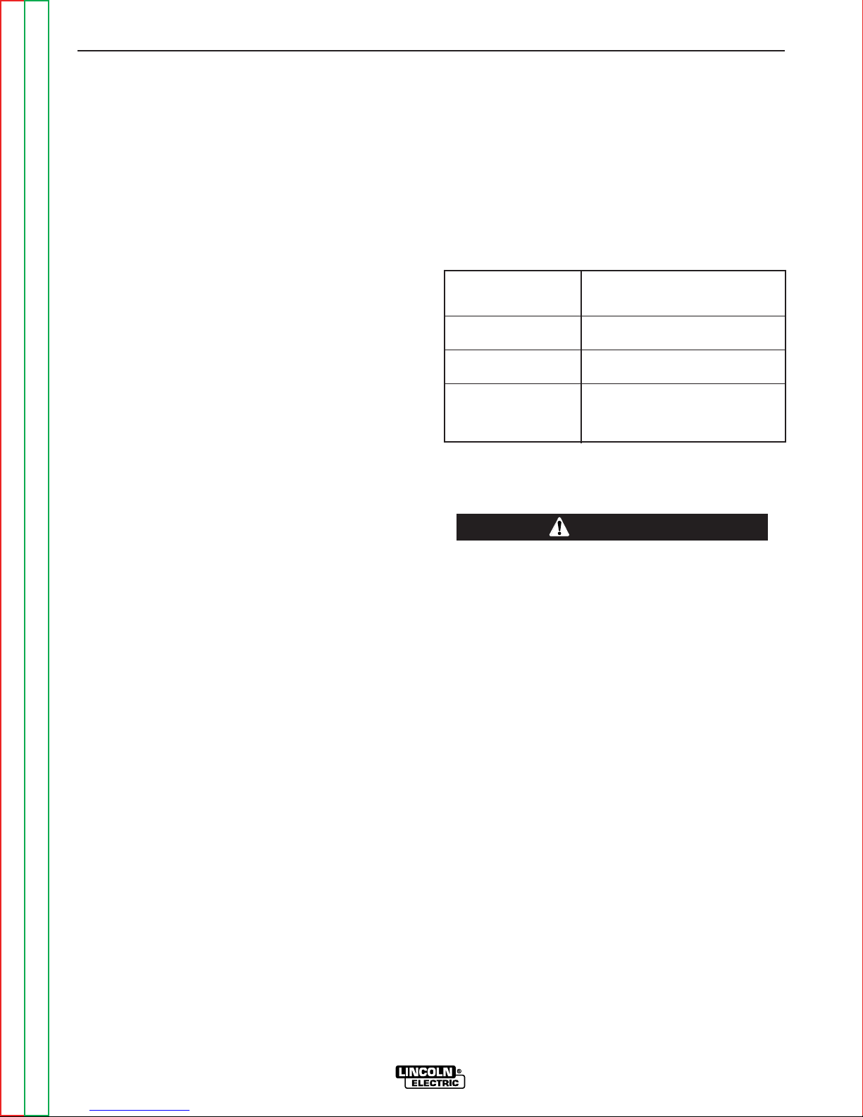
B-8 B-8
OPERATION
TIG WELDING
The TOUCH START TIG setting of the MODE switch is for DC
TIG (Tungsten Inert Gas) welding. To initiate a weld, the OUTPUT control is first set to the desired current and the tungsten is
touched to the work. During the time the tungsten is touching the
work there is very little voltage or current and, in general, no
tungsten contamination. Then the tungsten is gently lifted off the
work in a rocking motion, which establishes the arc.
The ARC CONTROL is not active in the TIG mode.
The Ranger 305D can be used in a wide variety of DC TIG welding applications. In general the “Touch Start” feature allows contamination-free starting without the use of a Hi-frequency unit. If
desired, the K930-2 TIG Module can be used with the Ranger
305D. See Table B.2 for reference settings.
Ranger 305D settings when using the K930-2 TIG Module with
an Amptrol or Arc Start Switch:
a. Set the MODE Switch to the TOUCH START TIG setting.
b. Set the “IDLER” Switch to the “AUTO” position.
c. Set the “WELD TERMINALS” switch to the “REMOTELY
CONTROLLED” position. This will keep the solid state contactor open and provide a “cold” electrode until the Amptrol or
Arc Start switch is pressed
ARC GOUGING
The RANGER 305D can be used for limited arc gouging. For optimal performance, set the MODE switch to
CC-STICK and the ARC CONTROL to +10.
Set the OUTPUT CONTROL knob to adjust output current to the desired level for the gouging electrode being
used according to the ratings in the following Table B.3
TABLE B.3 - CURRENT RANGE
PER ELECTRODE DIAMETER
Carbon Diameter
1/8" 75-140 Amps
5/32" 90-150 Amps
3/16" 200-250 Amps
Current Range (DC, electrode
positive)
AUXILIARY POWER
WARNING
When using the TIG Module, the OUTPUT control on the Ranger
305D is used to set the maximum range of the CURRENT.
WIRE WELDING-CV
Connect a wire feeder to the RANGER 305 D according to the
instructions in INSTALLATION INSTRUCTIONS Section.
In the CV-WIRE mode, the Ranger 305D can be used with a
broad range of flux cored wire (Innershield and Outershield)
electrodes and solid wires for MIG welding (gas metal arc welding). Welding can be finely tuned using the ARC CONTROL.
Turning the ARC CONTROL clockwise for -10 (soft) to +10
(crisp) changes the arc from soft and washed-in to crisp and narrow. It acts as an inductance control. The proper setting
depends on the procedure and operator preference. Start with
the dial set at 0.
Some recommended Innershield electrodes are: NR-311, NS3M, NR-203 Ni 1%, NR-204H. Recommended Outershield electrodes are :0S-70, OS-71M.
Some recommended solid wires for MIG welding are: .035
(0.9mm), and .045 (1.1mm), L-50 and L-56, .035 (0.9 mm) and
.045 (1.1mm) Blue Max MIG 308 LS.
For any electrodes, including those above, the procedure should
be kept within the rating of the machine.
Be sure that any electrical equipment plugged into the generator
AC power receptacles can withstand +/- 10% voltage and a +/3% frequency variation.
-----------------------------------------------------------------------
Start the engine and set the IDLER control switch to
the desired operating mode. Full power is available
regardless of the welding control settings as long as no
welding current is being drawn.
The auxiliary power of the Ranger 305D consists of
two 20 amp-120 VAC (5-20R) duplex receptacles and
one 50 amps 120/240 VAC (14-50R) receptacle. The
240 VAC receptacle can be split for single-phase 120
VAC operation.
The auxiliary power capacity is 10,000 watts peak,
9,500 watts of continuous 60 Hz, singe-phase power.
The auxiliary power capacity rating in watts is equivalent to volt-amperes at unity power factor. The maximum permissible, 40 amps continuous current of the
240 VAC output is 42 amps maximum.
NOTE: Machines with code numbers of 11121 and
higher are equipped with GFCI duplex receptacles. If
a GFCI receptacle is “tripped”, it will not reset unless
it is receiving nearly full voltage from the generator; for
this reason, the engine must be running at high RPM
before resetting a GFCI.
Return to Master TOC Return to Master TOC Return to Master TOC Return to Master TOC
Return to Section TOC Return to Section TOC Return to Section TOC Return to Section TOC
RANGER 305D
Page 25
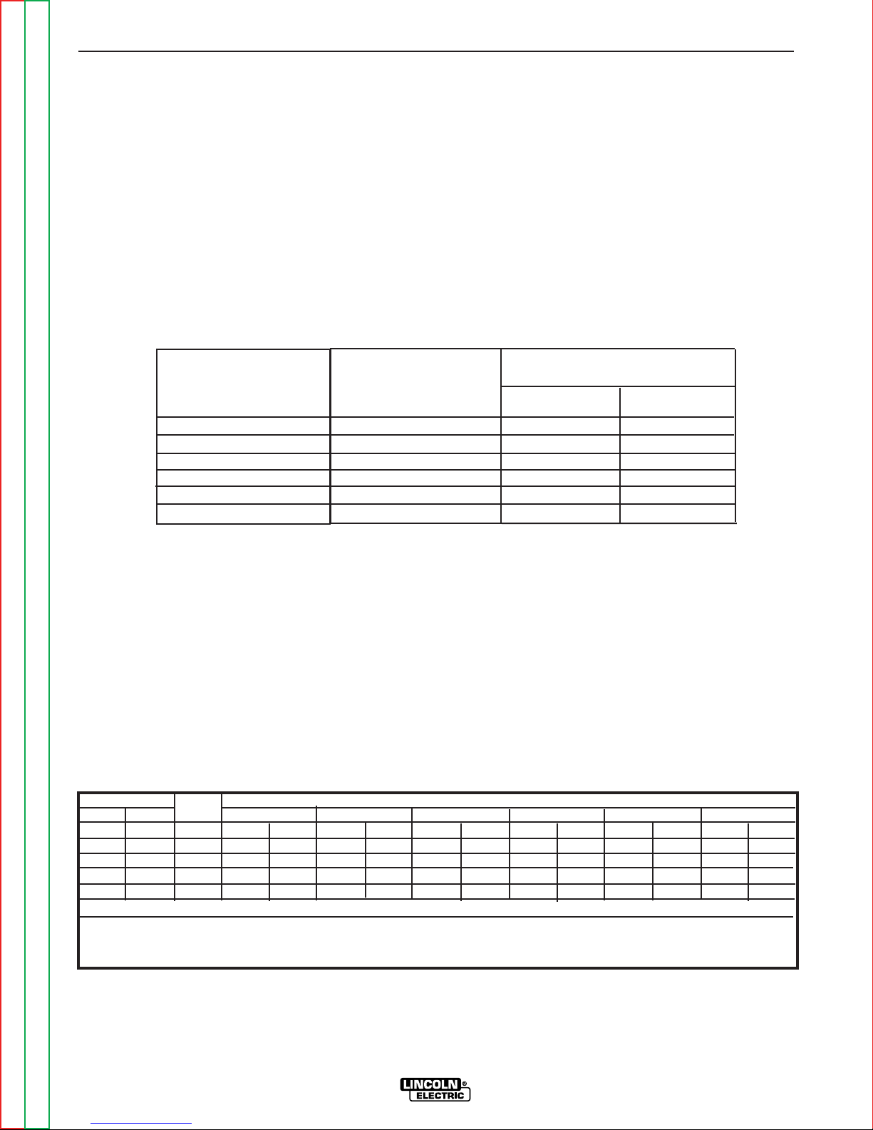
B-9 B-9
OPERATION
The 240 VAC receptacle can be split to provide two
separate120 VAC outputs with a maximum permissible
current of 42 amps pea, 40 amps continuous per outlet to two separate 20 amp branch circuits. (These circuits cannot be paralleled.) Output voltage is within +/10% at all loads up to rated capacity.
The 120 V auxiliary power receptacles should only be
used with three-wire, grounded type plugs or approved
double insulated tools with two-wire plugs. The current
rating of any plug used with the system must be at
least equal to the current capacity of the associated
receptacle. For extension cord lengths, see Table B.5.
RANGER 305D Simultaneous Welding and Power Loads
NOTE: The 240 VAC receptacle has two circuits, each
of which measure 120 VAC to neutral. However, they
are of opposite polarities and cannot be paralleled.
SIMULTANEOUS WELDING AND
AUXILIARY POWER LOADS
The above auxiliary power ratings are with no welding
load. Simultaneous welding and power loads are specified in Table B.4. The permissible currents shown
assume that current is being drawn from either the 120
VAC or 240 VAC supply (not both at the same time).
Current
(Amps)
15
20
15
20
33
Welding
Output-Amps
at NEMA Arc-Volts
Permissible Auxiliary
Power-Watts
(Unity Power Factor)
Permissible Auxiliary
Current in -Amps @
120 VAC* 240 VAC
0
100
150
200
250
300
9500
7100
5600
4500
2800
0
40*, (42* Peak) 40, (42 Peak)
40* 30
40* 23
32 16
16 8
0 0
* Each 120 VAC leg of the 120/240 VAC Full KVA receptacle can deliver a maximum
40 amps, up to a total of 80 amps at 9500 Watts, 60 amps at 7100 Watts, or 46
amps at 5600 Watts. These outputs cannot be paralleled, so the greatest single
120 VAC load is 40 amps.
Each 120 VAC Duplex receptacle is limited to 20 amps maximum.
TABLE B.5 - RANGER 305D Extension Cord Length Recommendations
(Use the shortest length extension cord possible sized per the following table.)
Voltage
(Volts)
120
120
240
240
240
Load
(Watts)
1800
2400
3600
4800
8000
14 AWG 12 AWG 10 AWG 8 AWG 6 AWG 4 AWG
30
60
(9)
(18)
Conductor size is based on maximum 2.0% voltage drop.
Maximum Allowable Cord Length in ft. (m) for Conductor Size
40
30
75
60
(12)
(9)
(23)
(18)
75
50
150
100
60
(23)
(15)
(46)
(30)
(18)
125
88
225
175
100
(38)
(27)
(69)
(53)
(30)
175
138
350
275
175
(53)
(42)
(107)
(84)
(53)
300
225
600
450
250
(91)
(69)
(183)
(137)
(76)
Return to Master TOC Return to Master TOC Return to Master TOC Return to Master TOC
Return to Section TOC Return to Section TOC Return to Section TOC Return to Section TOC
RANGER 305D
Page 26

B-10 B-10
NOTES
Return to Master TOC Return to Master TOC Return to Master TOC Return to Master TOC
Return to Section TOC Return to Section TOC Return to Section TOC Return to Section TOC
RANGER 305D
Page 27

Section C-1 Section C-1
TABLE OF CONTENTS
- ACCESSORIES -
Accessories...........................................................................................................................Section C
Options/Accessories ...................................................................................................................C-2
Field Installed Options .........................................................................................................C-2
TIG Welding Accessories .....................................................................................................C-2
Semiautomatic FCAW and MIG Welding Accessories.........................................................C-2
Connection of Lincoln Electric Wire Feeders .......................................................................C-3
Connection of the K867 Universal Adapter....................................................................C-3
Connection of the LN-25 “Across the Arc” .....................................................................C-4
Connection of the LN-25 with 42V Remote Output Control Module ..............................C-5
Connection of the LN-25 with K857 Remote Control .....................................................C-6
Connection of the LN-7 Using the K584 Control Cable .................................................C-7
Connection of the LN-8 Using the K595 Control Cable .................................................C-8
Connection of the LN-742 ..............................................................................................C-9
Return to Master TOC Return to Master TOC Return to Master TOC Return to Master TOC
RANGER 305D
Page 28

C-2 C-2
ACCESSORIES
Return to Section TOC Return to Section TOC Return to Section TOC Return to Section TOC
OPTIONS / ACCESSORIES
FIELD INSTALLED OPTIONS
The following options/accessories are available for
your Ranger 305D from your Lincoln distributor.
K957-1 HEAVY DUTY, TWO WHEEL TRAILER FOR
SMALL WELDERS - For road, off-road and in-plant
and yard towing. (For highway use, consult applicable
federal, state and local laws regarding requirements
for brakes, lights, fenders, etc.)
K1737-1 FOUR-WHEEL ALL-TERRAIN UNDERCARRIAGE - For moving by hand.
K1770-1 UNDERCARRIAGE (FACTORY) - For moving
by hand on a smooth surface. One or two gas cylinders
can be mounted on the rear of the undercarriage with the
installation of K1745-1 Cylinder Holder(s).
K1739-1 CABLE CARRIER KIT - For use on K1737-1
and K1770-1 Undercarriages.
K1745-1 SINGLE GAS CYLINDER HOLDER - For use
on K1770-1 Undercarriage. One or tow may be installed
on an undercarriage.
K1789-1 ROLL CAGE - Gives added damage protection.
K886-2 CANVAS COVER - Protects machine when
not in use.
K1898-1 SPARK ARRESTER - Attaches between
muffler or exhaust elbow.
K704 ACCESSORY KIT - Accessory set includes 35 ft.
(10.7meters) 2 AWG electrode cable, 30 ft. (9.1
meters) 2 AWG work cable, headshield with No. 12 filter, G300 work clamp and Cooltong 300 electrode
holder. Cables are rated at 300 amps, 40% duty cycle.
K857 28 ft (8.5m) or K857-1 100 ft. (30.4m)
REMOTE CONTROL - Portable control provides same
dial range as the output control on the welder. Has a
convenient 6-pin plug for easy connection to the
welder.
K1690-1 GFCI RECEPTACLE KIT - Includes one UL
approved 120 volt ground fault circuit interrupter
duplex type receptacle with cover and installation
instructions. Replaces the factory installed 120V
duplex receptacle. Each receptacle of the GFCI
Duplex is rated at 20 amps. The maximum total current from the GFCI Duplex is limited to 20 amps. Two
kits are required.
K802-N POWER PLUG KIT - Provides four 120 volt
plugs rated at 20 amps each and one dual voltage, full
KVA plug rated at 120/240 volts, 50 amps.
K802-R POWER PLUG KIT - Provides four 120 volt
plugs rated at 15 amps each and one dual voltage, full
KVA plug rated at 120/240 volts, 50 amps.
Return to Master TOC Return to Master TOC Return to Master TOC Return to Master TOC
T12153-9 50 AMP, 120/240V POWER PLUG -
Provides one dual voltage plug for full KVA power.
TIG WELDING ACCESSORIES
K1783-9 TIG TORCH - For TIG welding with shielding
gas. Includes 25 feet of cable.
K963-2 - Hand Amptrol.
K870 - Foot Amptrol
NOTE: TIG welding requires a Magnum
appropriate Magnum Parts Kit and argon gas.
SEMIAUTOMATIC FCAW AND MIG
WELDING ACCESSORIES
LN-25 WIRE FEEDER K449 - This portable unit pro-
vides CC/CV for flux-cored arc welding (FCAW) and
metal inert gas welding (MIG). Includes a gas solenoid
and an internal contactor that allows across-the-arc
operation with no control cable. The LN-25 provides a
“cold” electrode until the gun trigger is pressed. For
voltage control at the feeder, a K444-1 Remote Voltage
Control Kit or K857 Remote Control is required. Refer
to connection instructions later in this section.
LN-7 OR LN-8 WIRE FEEDER - Semiautomatic, constant speed wire feeders.
NOTE: Gas-shielding welding requires a Magnum
Gun. Gasless welding requires an Innershield Gun.
LN-742 WIRE FEEDER - A semiautomatic wire feeder
with “cold” electrode. Refer to connection instructions
later in this section.
MAGNUM SPOOL GUN (K487-25) - A lightweight,
semiautomatic wire feeder for aluminum welding with
argon gas. Has built-in remote wire speed control in
the handle. Requires the K488 SG Control Module.
Refer to connection instructions later in this section.
SG CONTROL MODULE (K488) - Controls wire speed
and gas flow. Provides the required control interface
between the Ranger 305D and the K487-25 Magnum
Spool Gun. Requires the K691-10 Input Cable.
K444-1 REMOTE VOLTAGE CONTROL - Provides
voltage adjustment control at the feeder. Includes 25
feet of cable.
K126-2 INNERSHIELD GUN - For gasless welding.
Includes 15 feet of cable.
K470-2 MAGNUM GUN CONNECTOR KIT - For gasshielding welding.
K466-1 MAGNUM GUN CONNECTOR KIT - For connecting the Magnum 300 MIG Gun to the feeder for
gas-shielding welding.
RANGER 305D
TM
TIG Gun,
Page 29
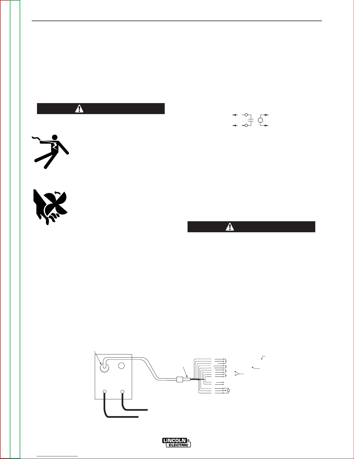
C-3 C-3
81
82
4
2
SPARE
31
42
41
77
21
GND
32
75
76
POWER SOURCE FRAME CONNECTION
WIRE FEEDER VOLTMETER CONNECTION
CONNECTS TO (WORK TERMINAL) OF POWER SOURCE
10K
MIN.
REMOTE OUTPUT CONTROL
115 VAC
42 VAC
WELDING OUTPUT
CONNECT TOGETHER FOR
NOT USED ON RANGER POWER SOURCES
A
B
C
+
-
ELECTRODE CABLE
TO WIRE FEED UNIT
TO WORK
K867 UNIVERSAL
ADAPTER PLUG
14-PIN
AMPHENOL
2
4
TO
K867
TO
WIRE
FEEDER
ACCESSORIES
K18161 FULL KVA ADAPTER KIT
Plugs into the 120/240V NEMA 14-0R receptacle on
the casefront (which accepts 4-prongs plugs) and converts it to a NEMA 6-50R receptacle, (which accepts 3prong plugs.)
CONNECTION OF LINCOLN
ELECTRIC WIRE FEEDERS
WARNING
ELECTRIC SHOCK can kill.
. Do not operate with panels open.
. Disconnect NEGATIVE (-) BATTERY
LEAD before servicing.
. Do not touch electrically live parts.
MOVING PARTS can injure.
. Keep guards in place.
. Keep away from moving parts.
. Only qualified personnel should
install, use or service this equipment.
2. Connect the electrode cable from the wire feeder to
the “+” terminal of the welder. Connect the work
cable to the “-” terminal of the welder.
NOTE: Welding cable must be sized for current and
duty cycle of application.
3. Connect the K867 Universal Adapter to the 14-pin
amphenol of the Ranger 305D as shown in Figure
C.1. Make the proper connections for local or
remote control according to Figure C.1. and the following NOTES, indicated on the figure:
A. These leads are not used for the Ranger
305D. Insulate each unused lead individually.
B. For wire feeders that return a signal for weld-
ing output, use an isolation relay to close
leads 2 and 4.
C. Refer to the Operation section of this manual
for maximum wire feeder auxiliary current
draw.
4. Set the “MODE” switch to the “CV-WIRE” position.
5. Place the “IDLER” switch in the “AUTO” position.
Return to Section TOC Return to Section TOC Return to Section TOC Return to Section TOC
------------------------------------------------------------------------
CONNECTION OF THE RANGER 305D TO
WIRE FEEDERS USING K867 UNIVERSAL
ADAPTER (SEE FIGURE C.1)
NOTE: When you use the Ranger 305D with non-
Lincoln Electric wire feeders or with certain earlier
models of Lincoln wire feeders, you will require the
K867 Universal Adapter. The following discussion and
connection diagram explain in general how to make the
proper connections.
1. Shut the welder off.
FIGURE C.1 - Ranger 305D/K867 UNIVERSAL ADAPTER CONNECTION DIAGRAM
Return to Master TOC Return to Master TOC Return to Master TOC Return to Master TOC
Any increase of the high idle engine RPM by changing the governor setting or overriding the throttle linkage will cause an increase in the AC auxiliary voltage.
If this voltage goes over 140 volts, wire feeder control
circuit may be damaged. The engine governor setting
is preset at the factory - do not adjust above RPM
specifications listed in this manual.
------------------------------------------------------------------------
6. Set the “VOLTMETER” switch to “+” or “-” depending on the polarity chosen.
7. Set the ARC control to “0” initially and adjust to suit.
8. Adjust wire feed speed at the wire feeder.
RANGER 305D
CAUTION
Page 30
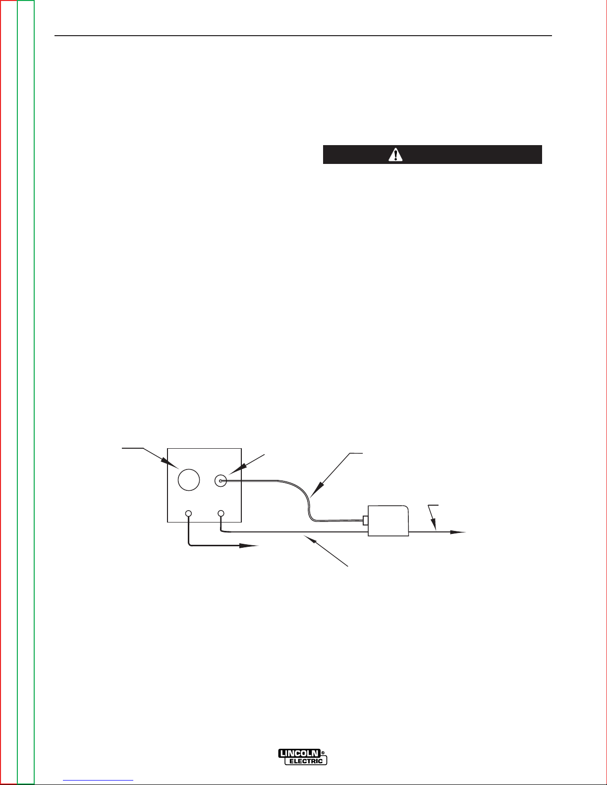
C-4 C-4
+
-
TO WORK
14-PIN
AMPHENOL
6-PIN
AMPHENOL
OPTIONAL K444-1
REMOTE CONTROL
ELECTRODE CABLE
LN-25
WIRE FEEDER
TO WORK
WORK CLIP LEAD
ACCESSORIES
CONNECTION OF THE LN-25 TO THE
RANGER 305D “ACROSS THE ARC”
(SEE FIGURE C.2.)
1. Shut the welder off.
2. Connect the electrode cable from the LN-25 to the
“-” terminal of the welder. Connect the work cable
to the “+” terminal of the welder.
NOTE: Figure C.2 shows the electrode connected for
negative polarity. To change polarity, shut the welder
off and reverse the electrode and work cables at the
Ranger 305D output terminals.
NOTE: Welding cable must be sized for current and
duty cycle of application.
3. Set the “VOLTMETER” switch to “+” or “-” depending on the polarity chosen.
4. Set the “MODE” switch to the “CV-WIRE” position.
5. Attach the single lead from the LN-25 control box
to the work using the spring clip on the end of the
lead. This is only a control lead - it carries no
welding current.
6. Place the “IDLER” switch in the “AUTO” or “HIGH”
position as desired.
CAUTION
If you are using an LN-25 without an internal contactor, the electrode will be “HOT” when the Ranger
305D is started.
------------------------------------------------------------------------
7. Place the “WELD TERMINALS” switch in the
“WELD TERMINALS ON” position.
8. Adjust wire feed speed at the LN-25 and adjust the
welding voltage with the output “CONTROL” at the
LN-25 if optional remote control kit is used.
9. Set the ARC control to “0” initially and adjust to
suit.
FIGURE C.2 - Ranger 305D/LN-25 ACROSS THE ARC CONNECTION DIAGRAM
Return to Master TOC Return to Master TOC Return to Master TOC Return to Master TOC
Return to Section TOC Return to Section TOC Return to Section TOC Return to Section TOC
RANGER 305D
Page 31

C-5 C-5
+
-
TO WORK
14-PIN
AMPHENOL
ELECTRODE CABLE
TO WIRE FEED UNIT
ELECTRODE CABLE
TO WIRE FEED UNIT
K626-XX INPUT CABLE ASSEMBLY
TO LN-25 INPUT
CABLE PLUG
ACCESSORIES
CONNECTION OF THE LN-25 TO THE
RANGER 305D WITH 42 VOLT REMOTE
OUTPUT CONTROL MODULE
(SEE FIGURE C.3.)
1. Shut the welder off.
2. Connect the electrode cable from the K626-XX
Input Cable Assembly to the “-” terminal of the
welder and to the LN-25 Wire Feeder. Connect
the work cable to the “+” terminal of the welder.
NOTE: Figure C.3 shows the electrode connected for
negative polarity. To change polarity, shut the welder
off and reverse the electrode and work cables at the
Ranger 305D output terminals.
NOTE: Welding cable must be sized for current and
duty cycle of application.
3. Connect the input cable from the K626-XX Input
Cable Assembly to the 14-pin amphenol on the
Ranger 305D and the input cable plug on the LN-
25.
5. Set the “MODE” switch to the “CV-WIRE” position.
6. Place the “IDLER” switch in the “AUTO” or “HIGH”
position as desired.
CAUTION
Any increase of the high idle engine RPM by changing
the governor setting or overriding the throttle linkage
will cause an increase in the AC auxiliary voltage. If
this voltage goes over 140 volts, wire feeder control circuit may be damaged. The engine governor setting is
preset at the factory - do not adjust above RPM specifications listed in this manual.
------------------------------------------------------------------------
7. Place the “WELD TERMINALS” switch in the
“REMOTELY CONTROLLED” position.
8. Adjust wire feed speed and voltage at the LN-25.
9. Set the ARC control to “0” initially and adjust to
suit.
4. Set the “VOLTMETER” switch to “+” or “-” depending on the polarity chosen.
FIGURE C.3 - Ranger 305D/LN-25 WITH
42 VOLT REMOTE OUTPUT CONTROL MODULE CONNECTION DIAGRAM
Return to Master TOC Return to Master TOC Return to Master TOC Return to Master TOC
Return to Section TOC Return to Section TOC Return to Section TOC Return to Section TOC
RANGER 305D
Page 32

C-6 C-6
+
-
TO WORK
14-PIN
AMPHENOL
6-PIN
AMPHENOL
OPTIONAL K857
REMOTE CONTROL
ELECTRODE CABLE
LN-25
WIRE FEEDER
TO WORK
WORK CLIP LEAD
ACCESSORIES
CONNECTION OF THE LN-25 TO THE
RANGER 305D “ACROSS THE ARC”
WITH K857 REMOTE CONTROL
(SEE FIGURE C.4.)
1. Shut the welder off.
2. Connect the electrode cable from the LN-25 to the
“-” terminal of the welder. Connect the work cable
to the “+” terminal of the welder.
NOTE: Welding cable must be sized for current and
duty cycle of application.
NOTE: Figure C.4 shows the electrode connected for
negative polarity. To change polarity, shut the welder
off and reverse the electrode and work cables at the
Ranger 305D output terminals.
If you are using an LN-25 without an internal contactor,
the electrode will be “HOT” when the Ranger 305D is
started.
------------------------------------------------------------------------
6. Set the “MODE” switch to “CV-WIRE.”
7. Set the “WELD TERMINALS” switch in the “WELD
TERMINALS ON” position.
8. Set the “VOLTMETER” switch to “+” or “-” depending on the polarity chosen.
9. Adjust the wire feed speed at the LN-25 and adjust
the welding voltage with the K857 if optional
remote control is used.
CAUTION
3. Connect the K857 Remote Control to the 6-pin
amphenol on the Ranger 305D.
4. Attach the single lead from the LN-25 to the work
using the spring clip on the end of the lead. This
is only a sense lead - it carries no welding current.
5. Place the “IDLER” switch in the “AUTO” or “HIGH”
position, as desired.
FIGURE C.4 - Ranger 305D/LN-25 ACROSS THE ARC
CONNECTION DIAGRAM WITH K857 REMOTE CONTROL
9. Adjust the ARC control to “0” initially and adjust to
suit.
Return to Master TOC Return to Master TOC Return to Master TOC Return to Master TOC
Return to Section TOC Return to Section TOC Return to Section TOC Return to Section TOC
RANGER 305D
Page 33

C-7 C-7
-
+
TO WORK
14-PIN
AMPHENOL
ELECTRODE CABLE
TO WIRE FEED UNIT
ELECTRODE CABLE
TO WIRE FEED UNIT
K584-XX CONTROL CABLE
TO LN-7 INPUT
CABLE PLUG
6-PIN
AMPHENOL
OPTIONAL K857
REMOTE CONTROL
ACCESSORIES
CONNECTION OF THE LN-7 TO THE
RANGER 305D USING K584 CONTROL
CABLE
(SEE FIGURE C.5.)
NOTE: If your LN-7 comes equipped with a K291 or
K404 input cable, refer to CONNECTIONS OF THE
LN-7 Using K867 UNIVERSAL ADAPTER, rather than
this discussion, to connect your Ranger 305D for wire
feed welding.
1. Shut the welder off.
2. Connect the electrode cable from the K584-XX
Control Cable to the “+” terminal of the welder and
to the LN-7 wire feeder. Connect the work cable
to the “-” terminal of the welder.
NOTE: Figure C.5 shows the electrode connected for
positive polarity. To change polarity, shut the welder
off and reverse the electrode and work cables at the
output terminals.
NOTE: Welding cable must be sized for current and
duty cycle of application.
3. Connect the input cable from the K584-XX Control
Cable to the 14-pin amphenol on the Ranger 305D
and the input cable plug on the LN-7.
4. Set the “VOLTMETER” switch to “+” or “-” depending on the polarity chosen.
5. Set the “MODE” switch to the “CV-WIRE” position.
6. Place the “IDLER” switch in the “HIGH” position.
CAUTION
Any increase of the high idle engine RPM by changing
the governor setting or overriding the throttle linkage
will cause an increase in the AC auxiliary voltage. If
this voltage goes over 140 volts, wire feeder control circuit may be damaged. The engine governor setting is
preset at the factory - do not adjust above RPM specifications listed in this manual.
------------------------------------------------------------------------
7. Place the “WELD TERMINALS” switch in the
“REMOTELY CONTROLLED” position.
8. Adjust the wire feed speed at the LN-7 and adjust
the welding voltage with the optional remote control is used.
9. Set the ARC control to “0” initially and adjust to
suit.
Return to Master TOC Return to Master TOC Return to Master TOC Return to Master TOC
Return to Section TOC Return to Section TOC Return to Section TOC Return to Section TOC
FIGURE C.5 - Ranger 305D/LN-7 WITH 584 CONTROL CABLE CONNECTION DIAGRAM
RANGER 305D
Page 34

C-8 C-8
+
-
TO WORK
14-PIN
AMPHENOL
ELECTRODE CABLE
TO WIRE FEED UNIT
TO LN-8 INPUT
CABLE PLUG
K595 CONTROL CABLE
ACCESSORIES
CONNECTION OF THE LN-8 TO THE
RANGER 305D USING K595 CONTROL
CABLE
(SEE FIGURE C.6.)
NOTE: If your LN-8 comes equipped with a K291 or
K404 input cable, refer to CONNECTIONS OF THE
LN-7 Using K867 UNIVERSAL ADAPTER, rather than
this discussion, to connect your Ranger 305D for wire
feed welding.
1. Shut the welder off.
2. Connect the electrode cable from the LN-8 to the
“+” terminal of the welder. Connect the work cable
to the “-” terminal of the welder.
NOTE: Welding cable must be sized for current and
duty cycle of application.
NOTE: Figure C.5 shows the electrode connected for
positive polarity. To change polarity, shut the welder
off and reverse the electrode and work cables at the
output terminals.
3. Connect the K595-XX Control Cable to the LN-8.
5. Place the “IDLER” switch in the “HIGH” position.
CAUTION
Any increase of the high idle engine RPM by changing
the governor setting or overriding the throttle linkage
will cause an increase in the AC auxiliary voltage. If
this voltage goes over 140 volts, wire feeder control circuit may be damaged. The engine governor setting is
preset at the factory - do not adjust above RPM specifications listed in this manual.
------------------------------------------------------------------------
6. Set the “VOLTMETER” switch to “+” or “-” depending on the polarity chosen.
7. Set the “MODE” switch to “CV-WIRE.”
8. Set the “WELD TERMINALS” switch to “WELD
TERMINALS REMOTELY CONTROLLED.”
9. Adjust wire feed speed and voltage at the LN-8.
10. Adjust the “ARC” control to “0” initially and adjust
to suit.
4. Connect the K595-XX to the 14-pin amphenol on
the Ranger 305D.
FIGURE C.6 - Ranger 305D/LN-8 WITH K595 CONTROL CABLE CONNECTION DIAGRAM
Return to Master TOC Return to Master TOC Return to Master TOC Return to Master TOC
Return to Section TOC Return to Section TOC Return to Section TOC Return to Section TOC
RANGER 305D
Page 35

C-9 C-9
+
-
TO WORK
14-PIN
AMPHENOL
ELECTRODE CABLE
TO WIRE FEED UNIT
ELECTRODE CABLE
TO WIRE FEED UNIT
K619 CONTROL CABLE
TO LN-742 INPUT
CABLE PLUG
ACCESSORIES
CONNECTION OF THE LN-742 TO THE
RANGER 305D.
(SEE FIGURE C.7.)
1. Shut the welder off.
2. Connect the electrode cable from the LN-742
to the “+” terminal of the welder. Connect the work
cable to the “-” terminal of the welder.
NOTE: Figure C.7 shows the electrode connected for
positive polarity. To change polarity, shut the welder
off and reverse the electrode and work cables at the
output terminals.
NOTE: Welding cable must be sized for current and
duty cycle of application.
An increase of the high idle engine RPM by changing
the governor setting or overriding the throttle linkage
will cause an increase in the AC auxiliary voltage. If
this voltage goes over 140 volts, wire feeder control circuit may be damaged. The engine governor setting is
preset at the factory - do not adjust above RPM specifications listed in this manual.
------------------------------------------------------------------------
7. Place the “WELD TERMINALS” switch in the
“REMOTELY CONTROLLED” position.
8. Adjust wire feed speed and voltage at the LN-742..
CAUTION
3. Connect the K619 Control Cable to the 14-pin
amphenol on the Ranger 305D and the input cable
plug on the LN-742..
4. Set the “VOLTMETER” switch to “+” or “-” depending on the polarity chosen.
5. Set the “MODE” switch to “CV-WIRE” position.
6. Place the “IDLER” switch in the “AUTO” or “HIGH”
position, as desired.
FIGURE C.7 - Ranger 305D/LN-742 CONNECTION DIAGRAM
9. Set the ARC control to “0” initially and adjust to
suit.
Return to Master TOC Return to Master TOC Return to Master TOC Return to Master TOC
Return to Section TOC Return to Section TOC Return to Section TOC Return to Section TOC
RANGER 305D
Page 36

C-10 C-10
NOTES
Return to Master TOC Return to Master TOC Return to Master TOC Return to Master TOC
Return to Section TOC Return to Section TOC Return to Section TOC Return to Section TOC
RANGER 305D
Page 37

Section D-1 Section D-1
TABLE OF CONTENTS
-MAINTENANCE-
Maintenance ..........................................................................................................................Section D
Safety Precautions......................................................................................................................D-2
Routine and Periodic Maintenance.............................................................................................D-2
Engine Maintenance.............................................................................................................D-3
Engine Oil Change ..............................................................................................................D-4
Oil Filter Change ..................................................................................................................D-4
Service Instruction & Installation Tips ..................................................................................D-5
Cooling System ....................................................................................................................D-6
Tighten the Fan Belt .............................................................................................................D-6
Fuel System Service ............................................................................................................D-7
Battery Maintenance.............................................................................................................D-7
Welder/Generator Maintenance..................................................................................................D-8
Storage .................................................................................................................................D-8
Cleaning ...............................................................................................................................D-8
Receptacles..........................................................................................................................D-8
Cable Connections ...............................................................................................................D-8
Brush Removal and Replacement........................................................................................D-8
GFCI Receptacle Testing and Resetting Procedure...................................................................D-9
Major Component Location.......................................................................................................D-10
Return to Master TOC Return to Master TOC Return to Master TOC Return to Master TOC
RANGER 305D
Page 38

D-2 D-2
MAINTENANCE
SAFETY PRECAUTIONS
WARNING
• Have qualified personnel do all maintenance and
troubleshooting work.
• Turn the engine off before working inside the
machine.
• Remove guards only when necessary to perform
maintenance and replace them when the maintenance requiring their removal is complete. If
guards are missing from the machine, obtain
replacements from a Lincoln Distributor. (See
Operating Machine Parts List.)
Read the Safety Precautions in the front of this
manual and in the diesel Operatorʼs Manual before
working on this machine.
Keep all equipment safety guards, covers, and
devices in position and in good repair. Keep hands,
hair, clothing, and tools away from the fans and all
other moving parts when starting, operating, or
repairing the equipment.
ROUTINE AND PERIODIC
MAINTENANCE
ENGINE MAINTENANCE
CAUTION
To prevent the engine from accidentally starting,
disconnect the negative battery cable before servicing
the engine.
------------------------------------------------------------------------
See Table D.2 for a summary of maintenance
intervals for the items listed in Table D.1. Follow
either the hourly or the calendar intervals, whichever
come first. More frequent servicing may be required,
depending on your specific application and operating
conditions. See Figure D.1 for major component
locations.
At the end of each dayʼs use, refill the tank to
minimize moisture condensation in the tank. Running
out of fuel tends to draw dirt into the fuel system.
Also, check the crankcase oil level and add oil if
indicated.
TABLE D.1 - ENGINE MAINTENANCE COMPONENTS, KUBOTA D722 DIESEL ENGINE
ITEM MAKE AND PART NUMBER
OIL FILTER KUBOTA 70000-15241
AIR FILTER DONALDOSON P822686
MAIN FUEL FILTER KUBOTA 15393-43017
FUEL FILTER (IN-LINE) KUBOTA 12581-43012
BATTERY GROUP 58, 550, CCA LINCOLN M9399-14
BELT KUBOTA 15881-97011
GLOW PLUGS KUBOTA 16851-65512
Return to Master TOC Return to Master TOC Return to Master TOC Return to Master TOC
Return to Section TOC Return to Section TOC Return to Section TOC Return to Section TOC
RANGER 305D
Page 39

D-3 D-3
MAINTENANCE
TABLE D.2 - KUBOTA D722 ENGINE MAINTENANCE SCHEDULE
INTERVAL REQUIRED MAINTENANCE
Daily Fill fuel tank
Check oil level
Check coolant level
Check air cleaner for dirt or damage
Check air intake for cracks/looseness
(200 hrs per Kubota)
Check fan belt tension
(Kubota Manual every 100 hrs)
First 50 Hours Check engine oil and oil filter
75 Hours Check engine oil
100 Hours Clean air cleaner element (1)
Clean fuel filter
Check battery electrolyte level
150 Hours Change oil filter
200 Hours Check radiator hoses and clamps
400 Hours Replace fuel filter
500 Hours Replace fan belt
Flush radiator
Remove sediment from fuel tank
800 Hours Check and adjust valve clearances (2)
1500 Hours Check fuel injector nozzle pressure (2)
3000 Hours Check fuel injection pump and timer (2)
Every Year Replace air cleaner element (1)
Every Two Years Replace battery
KUBOTA D722 DIESEL ENGINE
Note (1) - Service more frequently when used in dusty and/or
Note (2) - Consult your Kubota engine dealer for this service.
Return to Master TOC Return to Master TOC Return to Master TOC Return to Master TOC
Return to Section TOC Return to Section TOC Return to Section TOC Return to Section TOC
Replace radiator hoses and clamps
Replace fuel hoses and clamps
high ambient temperatures.
RANGER 305D
Page 40

D-4 D-4
MAINTENANCE
Engine Oil Change
Drain the engine oil while the engine
is warm to assure rapid and complete draining. It is recommended that each time the oil is changed the oil filter be changed as well. See Table D.2.
• Be sure the unit is off. Disconnect the negative bat-
tery cable to ensure safety.
• Locate oil drain hose and valve in bottom of base
and pull through the hole in the battery access panel
on the welder.
• Remove the cap from the drain valve. Push valve in
and twist counterclockwise. Pull to open and drain
the oil into a suitable container for disposal.
• Close the drain valve by pushing in and twisting
clockwise. Replace the cap.
• Re-fill the crankcase to the upper limit mark on the
dipstick with the recommended oil (see engine operation manual OR engine service items decal OR
below). Replace and tighten the oil filler cap securely.
• Push oil drain hose and valve back into unit, re-con-
nect negative battery cable, and close doors and
engine top cover before restarting unit.Wash your
hands with soap and water after handling used motor
oil. Please dispose of used motor oil in a manner
that is compatible with the environment. We suggest
you take it in a sealed container to your local service
station or recycling center for reclamation. DO NOT
throw it in the trash; pour it on the ground or down a
drain.
Wash your hands with soap and water after handling
used oil.
Please dispose of used motor oil in a manner that is
compatible with the environment. We suggest you
take it in a sealed container to your local service station or recycling center for reclamation. Do not throw it
in the trash, pour it on the ground or down a drain.
Oil Filter Change
• Drain the oil.
• Remove the oil filter with an oil filter wrench and drain
the oil into a suitable container. Discard the used filter. Note: Care should be taken during filter removal
to not disrupt or damage in any way the fuel lines.
• Clean the filter mounting base and coat the gasket
of the new filter with clean engine oil.
• Screw the new filter on by hand until the gasket con-
tacts the mounting base. Using an oil filter wrench,
tighten the filter an additional 1/2 to 7/8 of a turn.
• Refill the crankcase with the specified amount of the
recommended engine oil. Reinstall the oil filler cap
and tighten securely
• Start the engine and check for oil filter leaks.
• Stop the engine and check the oil level. If necessary,
add oil to the upper limit mark on the dipstick.
Return to Section TOC Return to Section TOC Return to Section TOC Return to Section TOC
Engine Oil Refill capacities
Without oil filter replacement:
• 3.3 U.S. Quart. (2.7 Imp Quart, 3.2 liter)
With oil filter replacement:
• 3.4 U.S. Quart. (3.0 Imp Quart, 3.2 liter)
Use motor oil designed for diesel engines that meets
requirements for API service classification Kubota
manual CD/CE/CF/CF-4/CG-4 or CH-4.
Oils levels that meet ACEA Performance levels E1, E2,
or E3 can also be used. Always check the service label
on the oil container to be sure it includes the letters
indicated. (Note: An S-grade oil must not be used in a
diesel engine or damage may result. It IS permissible
to use an oil that meets S and C grade service classifications.)
SAE 10W30 is recommended for general, all temperature use, 5F to 104F (-15C to 40C).
See engine ownerʼs manual for more specific information on oil viscosity recommendations.
Return to Master TOC Return to Master TOC Return to Master TOC Return to Master TOC
RANGER 305D
Page 41

D-5 D-5
Service Instructions & Installation Tips
For Engine Air Filter
Release the
1Seal Carefully
Unlatch and remove the service
cover of the air cleaner. Make
certain the latches are folded
back against the cover so that
they donít hinder filter
removal/installation. Most latches
are spring loaded to fold back when open.
The filter fits tightly over the outlet tube,
creating the critical seal on the inside
diameter of the filter endcap. The filter
should be removed gently to reduce the
amount of dust dislodged. There will be
some initial resistance, similar to breaking
the seal on a jar.
Gently move the end of the
filter back and forth to break the seal.
Avoid Dislodging
2Dust from the Filter
Gently pull the
filter off the outlet
tube and out of the
housing. Avoid
knocking the filter
against the housing.
Clean Sealing Surface
3of the Outlet Tube
Use a clean cloth to wipe the sealing
surface. Dust on the outside diameter of the
outlet tube could hinder
an effective seal
and cause leakage.
Make sure that all
contaminant is
removed before the
new filter is inserted.
Insert the New
7RadialSeal
ô
Filter
by Hand
Insert carefully. Seat the new filter by hand,
making certain it is completely into the air
cleaner housing
before latching the cover in
place. If the cover hits the filter before it is
fully in place, remove the cover and push
(by hand) the
filter further into
the air cleaner
and try again.
The cover
should go on
with no extra force.
Never use the latches on the cover to force
the filter into the air cleaner! It is tempting
to assume the cover will do the job of
seating the filter ñ but it will not! Using the
latches to push the filter in could cause
damage to the housing and will void the
warranty.
Donaldson filters with RadialSeal
™
Sealing
Technology are self-aligning, self-centering,
and self-sealing. A new filter has a dry
lubricant to aid installation. The critical
sealing area will stretch slightly, adjust
itself and distribute the sealing pressure
evenly. To complete a tight seal, apply
pressure by hand at the outer rim of the
filter, not the flexible center. (Avoid
pushing on the center of the urethane end
cap.) No cover pressure is required to hold
the seal. Again, do NOT use the service
cover to push the filter into place!
When the filter in is place, put the service
cover back on, making sure the Vacuator
™
Valve points down. Inspect the Vacuator
Valve for cracks or dust hang-ups to insure
that it is functioning properly. Re-fasten
the latches.
Check Connections
8for Tight Fit
Make sure that all clamps, bolts, and
connections in the entire air intake system
are tight. Check for holes in piping, and
repair if needed.
Clean the Inside of
4the Outlet Tube
Carefully wipe the inside
of the outlet tube
with a clean cloth.
Dirt accidently
transferred to the
inside of the outlet
tube will reach the
engine and cause wear.
(Engine manufacturers says that it takes
only a few grams of dirt to ëdustí an
engine!) Be careful not to damage the
sealing area on the tube.
Check the Old
5Filter for Leak Clues
Visually inspect the old filter for any signs
of leaks. A streak of dust on
the clean side of the filter
is a telltale sign.
Remove any cause
of leaks before
installing new
filter.
Inspect the New
6Filter for Damage
Inspect the new filter carefully,
paying attention to the inside of
the open end,
which is the
sealing area.
NEVER install
a damaged filter.
™
MAINTENANCE
Return to Master TOC Return to Master TOC Return to Master TOC Return to Master TOC
Return to Section TOC Return to Section TOC Return to Section TOC Return to Section TOC
RANGER 305D
Page 42

D-6 D-6
MAINTENANCE
COOLING SYSTEM
WARNING
Never use gasoline or low flash point solvents for
cleaning the air cleaner element. A fire or explosion
could result.
CAUTION
Never run the engine without the air cleaner. Rapid
engine wear will result from contaminants, such as dust
and dirt being drawn from the engine.
AIR CLEANER
The diesel engine is equipped with a dry type air filter.
Never apply oil to it. Service the air cleaner as follows:
------------------------------------------------------------------------
Check the coolant level by observing the level in the
radiator and recovery bottle. Add 50/50 antifreeze /
water solution if the level is close to or below the
"LOW" mark. Do not fill above the "FULL" mark.
Remove radiator cap and add coolant to radiator. Fill
up to the top of the tube in the radiator filler neck which
includes a connecting hose coming from the thermostat housing.
To drain the coolant, open the petcock at the bottom of
the radiator. Open the radiator cap to allow complete
drainage. (Tighten the petcock and refill with a 50/50
antifreeze/water solution.) Use an automotive grade
(low silicate) ethylene glycol antifreeze. The cooling
system capacity is 3.85 quarts (3.6L.). Squeeze upper
and lower radiator hoses while filling to bleed air from
system coolant. Replace and tighten the radiator cap.
WARNING
HOT COOLANT
• Do not remove cap if radiator is
hot.
can burn skin.
CAUTION
Always premix the antifreeze and clean tap water
before adding to the radiator. It is very important that a
precise 50/50 solution be used with this engine year
round. This gives proper cooling during hot weather
and freezing protection to -34° F (-37° C).
Cooling solution exceeding 50% antifreeze can result
in engine overheating and damage to the engine.
Coolant solution must be premixed before adding to
radiator.
------------------------------------------------------------------------
Periodically remove the dirt from the radiator fins.
Periodically check the fan belt and radiator hoses.
Replace if signs of deterioration are found.
TIGHTENING THE FAN BELT
If the fan belt is loose, the engine can overheat and the
battery lose its charge. Check tightness by pressing on
the belt midway between the pulleys. It should deflect
about 0.28 to 0.35 in. under a load of 22 lbs. (7 to 9
mm/10Kg).
Return to Master TOC Return to Master TOC Return to Master TOC Return to Master TOC
Return to Section TOC Return to Section TOC Return to Section TOC Return to Section TOC
RANGER 305D
Page 43

D-7 D-7
MAINTENANCE
FUEL SYSTEM SERVICE
At the end of each day, refill the fuel tank to minimize
moisture condensation and dirt contamination in the
fuel line. Do not overfill; leave room for expansion
Use only fresh, No. 2 grade DIESEL fuel. Do not use
kerosene. See the Engine Operatorʼs Manual for
instructions on replacing the fuel filter.
BLEEDING THE FUEL SYSTEM
You may need to bleed air from the fuel system if the
fuel filter or fuel lines have been detached, the fuel tank
has been run empty or after periods of long storage. It
is recommended that the fuel shutoff valve be closed
during periods of non-use.
(For Code 10926, 11121 )
The Kubota D722 engine supplied with this welder is
equipped with an automatic bleeding mechanism that
functions when the electric fuel pump is actuated. It is
generally not necessary to open a vent screw or fuel
line fitting to bleed the fuel system.
(For Code 11888, 11275 )
The Kubota D722 engine supplied with this welder is
equipped with an automatic bleeding mechanism that
helps purge the air from the mechanical fuel pump system. It is generally not necessary to open a vent screw
or fuel line fitting to bleed the fuel system. Operate the
priming lever on the pump to assist starting and after
extended periods of non-use or out of fuel conditions.
2. Replace the fuel filter if it is found with excessive
water accumulation or sediment. Empty fuel pre-filter.
OVERSPEED IS HAZARDOUS
The maximum allowable high idle speed for this
machine is 3650 RPM, no load. Do NOT tamper with
governor components or setting or make any other
adjustments to increase the maximum speed.
Severe personal injury and damage to the machine
can result if operated at speeds above maximum.
ENGINE ADJUSTMENT
Adjustments to the engine are to be made only by a
Lincoln Service Center or an authorized Field Service
Shop.
BATTERY MAINTENANCE
To access the battery, Disconnect the Negative and
then Positive battery cables. Remove the 2 screws
from the battery door using a screwdriver or a 3/8"
socket. Remove the 2 nuts from the battery bracket
using a 7/16” wrench or socket. Slide the battery out
and remove from welder
WARNING
GASES FROM BATTERY can
explode.
• Keep sparks, flame and cigarettes
away from battery.
Return to Section TOC Return to Section TOC Return to Section TOC Return to Section TOC
WARNING
To avoid personal injury, do not bleed a hot engine.
This could cause fuel to spill onto a hot exhaust
manifold, creating a danger of fire.
------------------------------------------------------------------------
Bleed the fuel system as follows:
1. Fill the fuel tank with fuel.
2. Open the fuel shut off valve (vertical position of han-
dle) on the Fuel Filter.
3. Press and hold the glow plug button for 10 to 20
seconds.(For Code 10926, 11121)
3a. Crank the engine by pressing the start button for 45
seconds. (For Code 11188, 11275)
4. Check to see that fuel is flowing through both fuel
filters
5. Follow the normal STARTING procedures.
FUEL FILTER
1. Check the fuel filter and fuel pre-filter for water accu-
mulation or sediment.
Return to Master TOC Return to Master TOC Return to Master TOC Return to Master TOC
To prevent EXPLOSION when:
• INSTALLING A NEW BATTERY — Disconnect
negative cable from old battery first and connect to
new battery last.
• CONNECTING A BATTERY CHARGER —
Remove battery from welder by disconnecting
negative cable first, then positive cable and battery
clamp. When reinstalling, connect
negative cable last. Keep well ventilated.
• USING A BOOSTER — Connect positive lead to
battery first, then connect negative lead to the
engine foot.
BATTERY ACID can burn eyes and
skin.
• Wear gloves and eye protection and
be careful when working near
battery.
• Follow instructions printed on battery.
RANGER 305D
Page 44

D-8 D-8
MAINTENANCE
CLEANING THE BATTERY
Keep the battery clean by wiping it with a damp cloth
when dirty. If the terminals appear corroded, disconnect the battery cables and wash the terminals with an
ammonia solution or a solution of 1/4 pound (0.1113
kg) of baking soda and 1 quart (0.9461) of water. Be
sure the battery vent plugs (if equipped) are tight so
that none of the solution enters the cells.
After cleaning, flush the outside of the battery, the battery compartment, and surrounding areas with clear
water. Coat the battery terminals lightly with petroleum
jelly or a non-conductive grease to retard corrosion.
Keep the battery clean and dry. Moisture accumulation
on the battery can lead to more rapid discharge and
early battery failure.
CHECKING THE ELECTROLYTE LEVEL
If battery cells are low, fill them to the neck of the filler
hole with distilled water and recharge. If one cell is low,
check for leaks.
CHARGING THE BATTERY
When you charge, jump, replace, or otherwise connect
battery cables to the battery, be sure the polarity is correct. Improper polarity can damage the charging circuit. The RANGER 305D positive (+) battery terminal
has a red terminal cover.
If you need to charge the battery with an external
charger, disconnect the negative cable first, then the
positive cable before you attach the charger leads.
After the battery is charged, reconnect the positive battery cable first and the negative cable last. Failure to do
so can result in damage to the internal charger components.
Follow the instructions of the battery charger manufacturer for proper charger settings and charging time.
WELDER / GENERATOR
MAINTENANCE
STORAGE: Store the RANGER 305D in clean, dry
protected areas.
CLEANING: Blow out the generator and controls periodically with low pressure air. Do this at least once a
week in particularly dirty areas.
RECEPTACLES: Keep the electrical receptacles in
good condition. Remove any dirt, oil, or other debris
from their surfaces and holes.
CABLE CONNECTIONS: Check the welding cable
connections at the weld output terminals often. Be
sure that the connections are always firm.
BRUSH REMOVAL AND REPLACEMENT: Itʼs normal
for the brushes and slip rings to wear and darken
slightly. Inspect the brushes when a generator overhaul is necessary.
CAUTION
Do not attempt to polish slip rings while the engine is
running.
WARNING
Service and Repair should only be performed by
Lincoln Electric Factory Trained Personnel.
Unauthorized repairs performed on this equipment
may result in danger to the technician and machine
operator and will invalidate your factory warranty. For
your safety and to avoid Electrical Shock, please
observe all safety notes and precautions.
OPTIONAL SPARK ARRESTOR
WARNING
MUFFLER MAY BE HOT.
Allow the engine to cool before installing the spark
arrestor!
Clean the spark arrestor after every 100 hours of use.
Return to Master TOC Return to Master TOC Return to Master TOC Return to Master TOC
Return to Section TOC Return to Section TOC Return to Section TOC Return to Section TOC
RANGER 305D
Page 45

D-9 D-9
MAINTENANCE
GFCI RECEPTACLE TESTING AND
RESETTING PROCEDURE
The GFCI receptacle should be properly tested at
least once every month or whenever it is tripped.
To properly test and reset the GFCI receptacle:
• If the receptacle has tripped, first carefully
remove any load and check it for damage.
• If the equipment has been shut down, it must
be restarted.
• The equipment needs to be operating at high
idle speed and any necessary adjustments
made on the control panel so that the equipment is providing at least 80 volts to the receptacle input terminals.
• The circuit breaker for this receptacle must not
be tripped. Reset if necessary.
• Push the "Reset" button located on the GFCI
receptacle. This will assure normal GFCI operation.
• Plug a night-light (with an "ON/OFF" switch) or
other product (such as a lamp) into the GFCI
receptacle and turn the product "ON".
• Push the "Test" button located on the GFCI
receptacle. The night-light or other product
should go "OFF".
• Push the "Reset" button, again. The light or
other product should go "ON" again.
If the light or other product remains "ON" when
the "Test" button is pushed, the GFCI is not working properly or has been incorrectly installed
(miswired). If your GFCI is not working properly,
contact a qualified, certified electrician who can
assess the situation, rewire the GFCI if necessary or replace the device.
Return to Master TOC Return to Master TOC Return to Master TOC Return to Master TOC
Return to Section TOC Return to Section TOC Return to Section TOC Return to Section TOC
RANGER 305D
Page 46

D-10 D-10
77
66
33
44
22
11
55
MAINTENANCE
FIGURE D.1 – MAJOR COMPONENT LOCATIONS
1. CASE FRONT ASSEMBLY
2. CONTROL PANEL ASSEMBLY
3. STATOR & ROTOR ASSEMBLY
4. BLOWER BAFFLE ASSEMBLY
5. BASE, FUEL TANK ASSEMBLY
6. ENGINE ASSEMBLY
7. CASE COVERS
Return to Master TOC Return to Master TOC Return to Master TOC Return to Master TOC
Return to Section TOC Return to Section TOC Return to Section TOC Return to Section TOC
RANGER 305D
Page 47

Section E-1 Section E-1
ROTOR
ENGINE
PROTECTION
CIRCUIT
ENGINE
PROTECTION
LIGHT
RUN
STOP
SWITCH
GLOW
PLUG
BUTTON
12V.
BATTERY
STARTER
ENGINE
ENGINE
SENSORS
GLOW
PLUGS
ENGINE
ALTERNATOR
START
BUTTON
IDLE
SOLENOID
PULL
COIL
HOLD
COIL
FUEL
PUMP
FUEL
SOLENIOD
PULL COIL
PULL COIL
PC BOARD
CHARGING
SYSTEM LIGHT
(CODE 10926 ONLY)
WELD
WINDING
STATOR
EXCITER
WINDING
120/240 VAC
AUX.WINDING
42 VAC
WINDING
240
VAC
CURRENT
SENSOR
14
PIN
120
vac
FLASHING
RECEPTACLES
HOLD COIL
6
PIN
AMPHENALS
OUTPUT
CONTROL
ARC
CONTROL
MODE
SWITCH
WELDING
TERMINAL
SWITCH
IDLE
SWITCH
AMP
DISPLAY
VOLT
DISPLAY
WELD CONTROL
P.C. BOARD
POWER
MODULE
IGBTs
SHUNT
+
CHOKE
-
TABLE OF CONTENTS
-THEORY OF OPERATION SECTION-
Theory of Operation..............................................................................................................Section E
General Description ..............................................................................................................E-2
Battery, Engine, Rotor, Stator and Engine Protection ...........................................................E-2
Engine Idle System................................................................................................................E-3
Generating Power..................................................................................................................E-4
Weld Power and Control........................................................................................................E-5
Remote Output Control, Output Contactor, Digital Meters ....................................................E-6
Chopper Technology Fundamentals......................................................................................E-7
Pulse Width Modulation.........................................................................................................E-8
Insulated Gate Bipolar Transistor (IGBT) Operation .............................................................E-8
FIGURE E.1 – RANGER 305D BLOCK LOGIC DIAGRAM
Return to Master TOC Return to Master TOC Return to Master TOC Return to Master TOC
RANGER 305D
Page 48

E-2 E-2
ROTOR
ENGINE
PROTECTION
CIRCUIT
ENGINE
PROTECTION
LIGHT
RUN
STOP
SWITCH
GLOW
PLUG
BUTTON
12V.
BATTERY
STARTER
ENGINE
ENGINE
SENSORS
GLOW
PLUGS
ENGINE
ALTERNATOR
START
BUTTON
IDLE
SOLENOID
PULL
COIL
HOLD
COIL
FUEL
PUMP
FUEL
SOLENIOD
PULL COIL
PULL COIL
PC BOARD
CHARGING
SYSTEM LIGHT
(CODE 10926 ONLY)
WELD
WINDING
STATOR
EXCITER
WINDING
120/240 VAC
AUX.WINDING
42 VAC
WINDING
240
VAC
CURRENT
SENSOR
14
PIN
120
vac
FLASHING
RECEPTACLES
HOLD COIL
6
PIN
AMPHENALS
OUTPUT
CONTROL
ARC
CONTROL
MODE
SWITCH
WELDING
TERMINAL
SWITCH
IDLE
SWITCH
AMP
DISPLAY
VOLT
DISPLAY
WELD CONTROL
P.C. BOARD
POWER
MODULE
IGBTs
SHUNT
+
CHOKE
-
THEORY OF OPERATION
FIGURE E.2 – BATTERY, ENGINE, ENGINE PROTECTION, CHARGING, IDLE CONTROL
GENERAL DESCRIPTION
The Ranger 305D is a diesel engine-driven welding
power source capable of producing 300 amps at
29VDC at a 100% duty cycle. The engine is coupled to
a brush-type alternating current generator. This AC
output is rectified then controlled by Chopper
Technology to produce DC current for multi-purpose
welding applications. The Ranger 305D is also capable of producing 9,500 watts (10,000 watts peak) of AC
auxiliary power at 100% duty cycle.
Battery, Engine, Engine Protection,
and Charging System.
BATTERY:
The 12VDC battery powers the engine starter motor,
glow plug circuit, engine protection circuit, fuel pump
(codes 10926 and 11121), and fuel solenoid. Power is
also supplied to other components.
Return to Master TOC Return to Master TOC Return to Master TOC Return to Master TOC
Return to Section TOC Return to Section TOC Return to Section TOC Return to Section TOC
NOTE: Unshaded areas of Block Logic Diagram are the subject of discussion.
RANGER 305D
Starting the engine:
Starting the engine first requires that the Run/Stop
switch be in the run position. The glow plug button is
then pressed and held; this preheats the engine to
enhance starting and also temporarily provides power
to the fuel pump (codes 10926 and 11121), and fuel
solenoid hold coil.
The start button is pressed while still holding the glow
plug button. The start button cranks the engine and
powers the fuel solenoid pull cord.
The engine starts, builds oil pressure, and spins the
engine alternator, which begins charging the battery.
The charging system indicator light (code 10926), and
the engine protection indicator will turn off. When the
engine protection light turns off, the fuel pump (codes
10926 and 11121), and fuel solenoid are receiving
power from the engine protection circuit. The operator
can now release the glow plug button.
The engine protection system now monitors the oil
pressure and coolant temperature sensors. If either
sensor detects a fault condition, the engine protection
indicator will light, and power will be interrupted to the
fuel solenoid, immediately shutting the engine off.
Page 49

E-3 E-3
ROTOR
ENGINE
PROTECTION
CIRCUIT
ENGINE
PROTECTION
LIGHT
RUN
STOP
SWITCH
GLOW
PLUG
BUTTON
12V.
BATTERY
STARTER
ENGINE
ENGINE
SENSORS
GLOW
PLUGS
ENGINE
ALTERNATOR
START
BUTTON
IDLE
SOLENOID
PULL
COIL
HOLD
COIL
FUEL
PUMP
FUEL
SOLENIOD
PULL COIL
PULL COIL
PC BOARD
CHARGING
SYSTEM LIGHT
(CODE 10926 ONLY)
WELD
WINDING
STATOR
EXCITER
WINDING
120/240 VAC
AUX.WINDING
42 VAC
WINDING
240
VAC
CURRENT
SENSOR
14
PIN
120
vac
FLASHING
RECEPTACLES
HOLD COIL
6
PIN
AMPHENALS
OUTPUT
CONTROL
ARC
CONTROL
MODE
SWITCH
WELDING
TERMINAL
SWITCH
IDLE
SWITCH
AMP
DISPLAY
VOLT
DISPLAY
WELD CONTROL
P.C. BOARD
POWER
MODULE
IGBTs
SHUNT
+
CHOKE
-
THEORY OF OPERATION
FIGURE E.3 –ENGINE IDLE SYSTEM, IDLE SWITCH & IDLE SOLENOID
Engine Idle System
Idle Switch Operation:
When the engine is started it operates at high RPM. If
the idle switch is in the high position the automatic idle system is inactive and the engine will continue to
operate at high RPM.
If the engine is started with the idle switch in the auto
position, or if the idle switch is moved to the
auto position while the engine is running, a 12 second
on the control PC board is started. If there is no significant current flow detected from the weld or auxiliary
outputs during that 12 second time, the idle solenoid
will be activated, dropping the engine RPM to preset
low idle speed. If a load is applied during the 12 second delay, the engine speed will remain high.
While operating at low RPM; if the idle switch is moved
to high, or there is a load detected from either the weld
of auxiliary outputs, the idle solenoid will be deactivated, allowing the engine governor to increase the RPM
to high speed.
When the idle switch is in the “auto” position and the
machine is under load and running at high RPM. If the
load is removed, the machine will continue to run at
high RPM for 12 seconds, then drop to low RPM,
unless a load is re-applied during that 12 second delay
Return to Master TOC Return to Master TOC Return to Master TOC Return to Master TOC
Return to Section TOC Return to Section TOC Return to Section TOC Return to Section TOC
NOTE: Unshaded areas of Block Logic Diagram are the subject of discussion.
RANGER 305D
Idle Solenoid Operation:
The engine speed is controlled by a two stage solenoid
connected to the engine speed control lever. When the
solenoid is inactive, the engine operates at high RPM,
and is controlled by the governor. When the solenoid
is activated, the speed control lever is pulled to a preset low RPM setting.
The solenoid is powered by battery voltage directly
from the run/stop switch. The control PC board and
pull coil PC board activate the pull and hold coils by
providing a path to ground.
When the machine goes to low idle speed, the control
PC board grounds the hold coil of the idle solenoid and
at the same time it sends a signal of about +14VDC to
the pull coil PC board. This DC signal remains at
+14VDC for the entire time that the hold coil is active.
When the signal is applied to the Pull coil PC board, the
board will energize the pull coil of the idle solenoid for
a brief moment, normally less than one second. This
momentary activation of the pull coil supplies the needed power to reliably move the speed control lever to the
low idle position.
Page 50

E-4 E-4
ROTOR
ENGINE
PROTECTION
CIRCUIT
ENGINE
PROTECTION
LIGHT
RUN
STOP
SWITCH
GLOW
PLUG
BUTTON
12V.
BATTERY
STARTER
ENGINE
ENGINE
SENSORS
GLOW
PLUGS
ENGINE
ALTERNATOR
START
BUTTON
IDLE
SOLENOID
PULL
COIL
HOLD
COIL
FUEL
PUMP
FUEL
SOLENIOD
PULL COIL
PULL COIL
PC BOARD
CHARGING
SYSTEM LIGHT
(CODE 10926 ONLY)
WELD
WINDING
STATOR
EXCITER
WINDING
120/240 VAC
AUX.WINDING
42 VAC
WINDING
240
VAC
CURRENT
SENSOR
14
PIN
120
vac
FLASHING
RECEPTACLES
HOLD COIL
6
PIN
AMPHENALS
OUTPUT
CONTROL
ARC
CONTROL
MODE
SWITCH
WELDING
TERMINAL
SWITCH
IDLE
SWITCH
AMP
DISPLAY
VOLT
DISPLAY
WELD CONTROL
P.C. BOARD
POWER
MODULE
IGBTs
SHUNT
+
CHOKE
-
THEORY OF OPERATION
FIGURE E.4 – GENERATING POWER & OUTPUT
Generating Power
Flashing:
The battery supplies 12VDC power to the control PC
board. When the engine protection light shuts off, the
control board allows the 12VDC “flashing” voltage to be
applied to the now rotating generator field winding, first
passed through a current limiting resistor, then through
the brushes and slip rings to frame ground.
Building Output:
The flashing current produces a weak magnetic field in
the rotor. This rotating magnetic field begins to generate AC output from all of the stator windings. Output
form the 42 VAC exciter winding is rectified by a diode
bridge, then filtered by a capacitor and fed back into the
rotating field winding, through the brushes, making the
magnetic field stronger. This stronger magnetic field
then produces higher voltage from the stator windings,
which feeds back to the rotor, making its magnetic field
even stronger.
This process of strengthening the magnetic field
through feedback from the output continues to increase
Return to Master TOC Return to Master TOC Return to Master TOC Return to Master TOC
Return to Section TOC Return to Section TOC Return to Section TOC Return to Section TOC
RANGER 305D
the output of the main generator until the design voltage is reached. The output of the machine depends on
engine RPM and rotor current.
The field voltage is now considerably higher than the
flashing voltage that was used to start the generating
process. Circuitry in the control PC board blocks that
higher field voltage from intruding into the 12VDC battery system.
AC output:
The generator is now producing sufficient AC power
from all four of the windings. These windings consist of
60 to 65 VAC three phase weld winding, a 120/240 VAC
auxiliary power winding, a 42 VAC exciter winding, and
a 42 VAC wire feeder power winding.
DC output:
The output from the three phase weld winding is converted to DC by a three phase output rectifier then filtered by four large capacitors located on the power
module assembly. This produces about 90VDC power
that supplies the IGBTs on the power module and the
weld control PC board.
Page 51

E-5 E-5
ROTOR
ENGINE
PROTECTION
CIRCUIT
ENGINE
PROTECTION
LIGHT
RUN
STOP
SWITCH
GLOW
PLUG
BUTTON
12V.
BATTERY
STARTER
ENGINE
ENGINE
SENSORS
GLOW
PLUGS
ENGINE
ALTERNATOR
START
BUTTON
IDLE
SOLENOID
PULL
COIL
HOLD
COIL
FUEL
PUMP
FUEL
SOLENIOD
PULL COIL
PULL COIL
PC BOARD
CHARGING
SYSTEM LIGHT
(CODE 10926 ONLY)
WELD
WINDING
STATOR
EXCITER
WINDING
120/240 VAC
AUX.WINDING
42 VAC
WINDING
240
VAC
CURRENT
SENSOR
14
PIN
120
vac
FLASHING
RECEPTACLES
HOLD COIL
6
PIN
AMPHENALS
OUTPUT
CONTROL
ARC
CONTROL
MODE
SWITCH
WELDING
TERMINAL
SWITCH
IDLE
SWITCH
AMP
DISPLAY
VOLT
DISPLAY
WELD CONTROL
P.C. BOARD
POWER
MODULE
IGBTs
SHUNT
+
CHOKE
-
THEORY OF OPERATION
FIGURE E.5 – WELD POWER & CONTROL
Weld Power and Control
Weld Power:
Approximately 90VDC power, as described earlier
under the heading “Generating Power”, is supplied to
the IGBTʼs, (See IGBT Operation) and to the control circuitry in the power module, as well as the weld control
PC board.
The IGBTʼs control the weld output by switching the
weld power on and off using a 20 Khz PWM (Pulse
Width Modulation) signal from the control PC board.
This PWM signal varies the ratio of on and off time,
thereby controlling the power passing through to the
welding arc. (See Pulse Width Modulation)
Return to Master TOC Return to Master TOC Return to Master TOC Return to Master TOC
Return to Section TOC Return to Section TOC Return to Section TOC Return to Section TOC
RANGER 305D
The DC power that is being controlled by the IGBTʼs is
now applied to the choke. The choke is a heavy conductor wound around an iron core. This device stores
power and tends to resist any change to current flow.
During the IGBT off cycle, the choke begins to discharge through a freewheeling diode, on the power
module. This diode provides the necessary current
path, allowing the choke to use its stored power to
maintain a smooth flow of current to the welding arc
during the IGBTʼs off times. (See Chopper
Technology Fundamentals)
Weld Control and Feedback:
The operator provides input to the weld control circuitry
by means of the output control and arc control potentiometers, and the mode switch. These operator inputs
are used by the microprocessor, together with pre-programmed internal parameters, current feedback from
the shunt, and voltage feedback from the output studs,
to control the IGBTʼs via the PWM signal discussed earlier.
Page 52

E-6 E-6
THEORY OF OPERATION
Remote output control:
The Weld control PC board automatically detects
when a remote control potentiometer is connected to
either of the Amphenols. In “CC-STICK”, “DOWNHILL PIPE” or “CV-WIRE” modes, the front panel output control is disabled when a remote control device
is connected. In “TOUCH START TIG” mode, the
front panel output control potentiometer is used to set
the maximum output value. The remote potentiometer varies the output from minimum to maximum value
set by the front panel control.
Electronic Output Contactor:
The operator also has the ability to control when
power is delivered to the output studs. This is accomplished by signaling the control PC board when to
send the PWM signal to the chopper module. Turning
the PWM signal on or off has the same effect as activating or deactivating an output contactor, and is
accomplished by closing the circuit between the #2
and #4 leads. The welding terminal switch closes this
circuit when it is placed in the “WELD TERMINALS
ON” position. When the switch is placed in the
“REMOTELY CONTROLLED” position, the circuit is
closed by a TIG foot pedal, a control cable type wire
feeder, or other remote control devices that can be
plugged into either the 6 pin or the 14 pin Amphenol.
Digital Meters:
Two identical digital displays are connected to the
control PC board and are used to indicate weld outputs Amps and Volts. When no current is flowing, the
machine is in “preset” mode and only one of the displays will be active. If mode switch is set for “CVWIRE”, only the volts display will be active; in all
other modes, only the amps display will be active.
When weld current is flowing, both displays will indicate actual weld volts and amps.
Return to Master TOC Return to Master TOC Return to Master TOC Return to Master TOC
Return to Section TOC Return to Section TOC Return to Section TOC Return to Section TOC
RANGER 305D
Page 53

E-7 E-7
THEORY OF OPERATION
CHOPPER TECHNOLOGY
FUNDAMENTALS
The new era of welding machines such as the Ranger
305D employ a technology whereby a DC source is
turned on and off (chopped up) at high speed, then
smoothed through an inductor to control an arc.
3 PHASE
ALTERNATOR
In this system, the engine drives a three-phase alternator, which generates power that is rectified and filtered to produce about 90 VDC. The current is applied
through a solid state switch to an inductor. By turning
DC RECTIFIER
AND FILTER
SOLID STATE
SWITCH
CONTROL
Hence the name “Chopper.” The biggest advantage of
chopper technology is the high-speed control of the
arc, similar to the inverter machines. A block diagram
for this is as follows:
INDUCTOR
AND DIODE
ARC
the switch on and off, current in the inductor and the
arc can be controlled. The following diagram depicts
the current flow in the system when the switch is open
and closed:
ARC
Return to Section TOC Return to Section TOC Return to Section TOC Return to Section TOC
90 VDC
When the switch is closed, current is applied through
the inductor to the arc. When the switch opens, current
stored in the inductor sustains flow in the arc and
through the diode. The repetition rate of switch closure
is 20Khz, which allows ultra-fast control of the arc. By
Return to Master TOC Return to Master TOC Return to Master TOC Return to Master TOC
INDUCTOR
SWITCH
ARC
DIODE
CURRENT WITH SWITCH OPEN
CURRENT WITH SWITCH CLOSED
varying the ratio of on time versus off time of the switch
(Duty Cycle), the current applied to the arc is controlled. This is the basis for Chopper Technology:
Controlling the switch in such a way as to produce
superior welding.
RANGER 305D
Page 54

E-8
THEORY OF OPERATION
FIGURE E.6 – IGBT OPERATION
E-8
PULSE WIDTH MODULATION:
The term PULSE WIDTH MODULATION is used to
describe how much time is devoted to conduction in the
cycle. Changing the pulse width is known as MODULATION. Pulse Width Modulation (PWM) is the varying
of the pulse width over the allowed range of a cycle to
affect the output of the machine.
MINIMUM OUTPUT:
By controlling the duration of the gate signal, the IGBT
is turned on and off for different durations during a
cycle. The top drawing shows the minimum output signal possible over a 50-microsecond time period.
The positive portion of the signal represents one IGBT
group conducting for 2 microseconds. The dwell time
(off time) is 48 microseconds. Since only 2 microseconds of the 50-microsecond time period is devoted to
conducting, the output power is minimized.
MAXIMUM OUTPUT:
By holding the gate signals on for 48 microseconds and
allowing only 2 microseconds of dwell time (off time)
during the 50-microsecond cycle, the output is maximized. The darkened area under the top curve can be
compared to the area under the bottom curve. The
more darkened area under the curve, the more power
is present.
Return to Master TOC Return to Master TOC Return to Master TOC Return to Master TOC
Return to Section TOC Return to Section TOC Return to Section TOC Return to Section TOC
RANGER 305D
Page 55

Section F-1 Section F-1
TABLE OF CONTENTS
TROUBLESHOOTING & REPAIR SECTION
Troubleshooting & Repair Section ................................................................................Section F
How to Use Troubleshooting Guide.......................................................................................F-2
PC Board Troubleshooting Procedures .................................................................................F-3
Troubleshooting Guide ................................................................................................F-4 - F-20
Test Procedures...................................................................................................................F-21
Case Cover Removal and Replacement Procedure ....................................................F-21
Chopper Module Capacitor Discharge Procedure ........................................................F-23
Fuel Shutdown Solenoid Test........................................................................................F-25
Engine Throttle Adjustment Test....................................................................................F-29
Idler Solenoid Test.........................................................................................................F-33
Engine Alternator Test ...................................................................................................F-35
Brush and Slip Ring Service Procedure........................................................................F-37
Rotor Resistance and Ground Test ...............................................................................F-39
Rotor Resistance and Ground Test ...............................................................................F-41
Rotor Voltage Test.........................................................................................................F-43
Flashing Voltage Test ....................................................................................................F-47
Stator Voltage Test .......................................................................................................F-51
Stator Short Circuit & Ground Test ...............................................................................F-55
Output rectifier Bridge Test ...........................................................................................F-57
Chopper Module Function Test ....................................................................................F-61
Chopper Module Resistance Test ................................................................................F-65
Weld Control Board PWM Gate Signal Test ................................................................F-69
Weld Control Feedback Test .........................................................................................F-71
Control Potentiometer and Mode Switch Resistance Test ............................................F-75
Remote Receptacle Test ...............................................................................................F-79
Replacement Procedures ....................................................................................................F-83
Output Rectifier Bridge and Choke Removal and Replacement...................................F-83
Chopper Module Removal and Replacement ...............................................................F-87
Engine/Stator/Rotor Removal and Replacement ..........................................................F-91
Oscilloscope Waveforms......................................................................................................F-97
Normal Open Circuit Voltage Waveform (120 VAC Supply)..........................................F-97
Normal Open Circuit Voltage Waveform (Stick)............................................................F-98
Normal Weld Voltage Waveform (Stick CC)..................................................................F-99
Normal Open Circuit Voltage Waveform (Wire CV Tap)..............................................F-100
Normal Weld Voltage Waveform (Wire CV) ................................................................F-101
Retest After Repair.............................................................................................................F-102
Return to Master TOC Return to Master TOC Return to Master TOC Return to Master TOC
RANGER 305D
Page 56

F-2 F-2
TROUBLESHOOTING & REPAIR
HOW TO USE TROUBLESHOOTING GUIDE
WARNING
Service and repair should be performed by only Lincoln Electric Factory Trained Personnel.
Unauthorized repairs performed on this equipment may result in danger to the technician and machine
operator and will invalidate your factory warranty. For your safety and to avoid Electrical Shock, please
observe all safety notes and precautions detailed throughout this manual.
This Troubleshooting Guide is provided to help
you locate and repair possible machine malfunctions. Simply follow the three-step procedure listed below.
Step 1. LOCATE PROBLEM (SYMPTOM). Look
under the column labeled “PROBLEM” (SYMPTOMS). This column describes possible symptoms that the machine may exhibit. Find the listing that best describes the symptom that the
machine is exhibiting. Symptoms are grouped
into four main categories: Output Problems,
Function Problems, Engine Problems, and
Welding Problems.
Step 2. PERFORM EXTERNAL TESTS. The
second column, labeled “POSSIBLE AREAS OF
MISADJUSTMENT(S)”, lists the obvious external
possibilities that may contribute to the machine
symptom. Perform these tests/checks in the
order listed. In general, these tests can be conducted without removing the case cover.
Step 3. PERFORM COMPONENT TESTS. The
last column, labeled “Recommended Course of
Action” lists the most likely components that may
have failed in your machine. It also specifies the
appropriate test procedure to verify that the subject component is either good or bad. If there are
a number of possible components, check the
components in the order listed to eliminate one
possibility at a time until you locate the cause of
your problem.
All of the referenced test procedures referred to in
the Troubleshooting Guide are described in detail
at the end of this section. Refer to the
Troubleshooting and Repair Table of Contents to
locate each specific Test Procedure. All of the
referred to test points, components, terminal
strips, etc., can be found on the referenced electrical wiring diagrams and schematics. Refer to
the Electrical Diagrams Section Table of Contents
to locate the appropriate diagram.
If for any reason you do not understand the test procedures or are unable to perform the test/repairs
safely, contact the Lincoln Electric Service Department for electrical troubleshooting assistance before
you proceed. Call 1-888-935-3877.
Return to Master TOC Return to Master TOC Return to Master TOC Return to Master TOC
Return to Section TOC Return to Section TOC Return to Section TOC Return to Section TOC
CAUTION
RANGER 305D
Page 57

F-3 F-3
TROUBLESHOOTING & REPAIR
PC BOARD TROUBLESHOOTING PROCEDURES
WARNING
ELECTRIC SHOCK can kill.
Have an electrician install and service
this equipment. Turn the machine OFF
before working on equipment. Do not
touch electrically hot parts.
Sometimes machine failures appear to be due to PC
board failures. These problems can sometimes be
traced to poor electrical connections. To avoid problems when troubleshooting and replacing PC boards,
please use the following procedure:
1. Determine to the best of your technical ability that
the PC board is the most likely component causing
the failure symptom.
2. Check for loose connections at the PC board to
assure that the PC board is properly connected.
3. If the problem persists, replace the suspect PC
board using standard practices to avoid static electrical damage and electrical shock. Read the warning inside the static resistant bag and perform the
following procedures:
PC Board can be damaged by static electricity.
• Remove your bodyʼs static charge
before opening the static-shielding bag. Wear an anti-static wrist
strap. For safety, use a 1 Meg
ohm resistive cord connected to a
grounded part of the equipment
ATTENTION
Static-Sensitive
Devices
Handle only at
Static-Safe
Workstations
Reusable
Container
Do Not Destroy
frame.
• If you donʼt have a wrist strap,
touch an unpainted, grounded,
part of the equipment frame.
Keep touching the frame to prevent static build-up. Be sure not
to touch any electrically live parts
at the same time.
• Tools which come in contact with
the PC Board must be either conductive, anti-static or static-dissipative.
• Remove the PC Board from the static-shielding bag
and place it directly into the equipment. Donʼt set the
PC Board on or near paper, plastic or cloth which
could have a static charge. If the PC Board canʼt be
installed immediately, put it back in the static-shielding
bag.
• If the PC Board uses protective shorting jumpers,
donʼt remove them until installation is complete.
• If you return a PC Board to The Lincoln Electric
Company for credit, it must be in the static-shielding
bag. This will prevent further damage and allow proper failure analysis.
4. Test the machine to determine if the failure symp-
tom has been corrected by the replacement PC
board.
NOTE: Allow the machine to heat up so that all electrical components can reach their operating temperature.
5. Remove the replacement PC board and substitute
it with the original PC board to recreate the original
problem.
a. If the original problem does not reappear
by substituting the original board, then the
PC board was not the problem. Continue
to look for bad connections in the control
wiring harness, junction blocks, and terminal strips.
b. If the original problem is recreated by the
substitution of the original board, then the
PC board was the problem. Reinstall the
replacement PC board and test the
machine.
6. Always indicate that this procedure was followed
when warranty reports are to be submitted.
NOTE: Following this procedure and writing on the
warranty report, “INSTALLED AND SWITCHED PC
BOARDS TO VERIFY PROBLEM,” will help avoid
denial of legitimate PC board warranty claims.
Return to Master TOC Return to Master TOC Return to Master TOC Return to Master TOC
Return to Section TOC Return to Section TOC Return to Section TOC Return to Section TOC
RANGER 305D
Page 58

F-4 F-4
TROUBLESHOOTING & REPAIR
Observe Safety Guidelines
detailed in the beginning of this manual.
PROBLEMS
(SYMPTOMS)
POSSIBLE AREAS OF
MISADJUSTMENT(S)
POWER OUTPUT PROBLEMS
Major mechanical or electrical
damage is evident.
No welding output or auxiliary
power. The engine operates normally.
No welding output in any mode.
The auxiliary output is normal. The
engine operates normally.
1. Contact your local Lincoln
1. Check for loose or faulty con-
1. Place the Welding Terminals
2. With the engine at high idle
Authorized Field Service
Facility.
nections at any leads, cables or
cords attached to either the auxiliary output receptacles and/or
the weld output terminals.
switch in the “WELD TERMINALS ON” position. If the problem is solved, the fault may be in
the external control cable, or the
attached wire feeder, amptrol,
arc start switch, etc. (if used)
(3650RPM), the machine in the
CC-STICK mode, the output
control at maximum, and the
welding terminals switch in the
“WELD TERMINALS ON” position; check for the presence of
approximately 58VDC, OCV
(open circuit voltage) at the weld
output terminals.
TROUBLESHOOTING GUIDE
RECOMMENDED
COURSE OF ACTION
1. Contact the Lincoln Electric
Service Department at 1-888935-3877.
1. Check the brushes for wear and
proper contact to the rotor slip
rings.
2. Perform the Brush and Slip
Ring Service procedure.
3. Perform the Rotor VoltageTest.
4. Perform the Stator Voltage
Test.
1. Check for damaged conductors
or faulty connections on the
heavy current carrying leads
that connect the output studs to
the Chopper module and to the
output Rectifier. Also Check
the shunt and choke assemblies for damage and faulty
connections.
2. Perform the Chopper Module
Function Test.
If for any reason you do not understand the test procedures or are unable to perform the test/repairs safely,
contact the Lincoln Electric Service Department for electrical troubleshooting assistance before you proceed. Call
1-888-935-3877.
Return to Master TOC Return to Master TOC Return to Master TOC Return to Master TOC
Return to Section TOC Return to Section TOC Return to Section TOC Return to Section TOC
3. If the correct OCV is present at
the welding output terminals,
check the welding
cables,connectors, work
clamps, electrode holder, etc. for
loose or faulty connections.
CAUTION
RANGER 305D
Page 59

F-5 F-5
TROUBLESHOOTING & REPAIR
TROUBLESHOOTING GUIDE Observe Safety Guidelines
detailed in the beginning of this manual.
PROBLEMS
(SYMPTOMS)
No auxiliary power at one or more
receptacles, or at the 14 pin
Amphenol receptacle. Weld output
is normal, and the engine operates
normally.
The machine has low welding output and low auxiliary output.
POSSIBLE AREAS OF
MISADJUSTMENT(S)
POWER OUTPUT PROBLEMS
1. Check for loose or faulty con-
nections at any cords attached
to the auxiliary output receptacles, or to the 14 pin Amphenol
receptacle.
1. The engine RPM may be too
low.
2. The brushes may be worn,
sticking, or poorly seated.
RECOMMENDED
COURSE OF ACTION
1. Check for tripped circuit breakers and/or tripped GFCI receptacles.
2. Perform the Stator Voltage
Tests.
1. The high idle speed may be low.
Perform the Engine Throttle
Adjustment Test.
NOTE: If the engine high idle RPM
is normal, but the engine slows
down excessively when the
machine is placed under a normal
welding or auxiliary load. The
engine may have lost horsepower,
and may be in need of service.
NOTE: Normal Full load engine
speed should be about 3500 RPM.
CAUTION
2. Inspect and, if necessary, service the brushes and slip rings
per the Brush and Slip Ring
Service procedure.
3. Perform the Rotor Voltage
Test.
4. Perform the Stator Voltage
Test.
If for any reason you do not understand the test procedures or are unable to perform the test/repairs safely,
contact the Lincoln Electric Service Department for electrical troubleshooting assistance before you proceed. Call
1-888-935-3877.
Return to Master TOC Return to Master TOC Return to Master TOC Return to Master TOC
Return to Section TOC Return to Section TOC Return to Section TOC Return to Section TOC
RANGER 305D
Page 60

F-6 F-6
TROUBLESHOOTING & REPAIR
Observe Safety Guidelines
detailed in the beginning of this manual.
PROBLEMS
(SYMPTOMS)
POSSIBLE AREAS OF
MISADJUSTMENT(S)
WELD OUTPUT PROBLEMS
The machine will weld, but the
welding arc is “cold”. The engine
runs normally and the auxiliary
power is normal.
1. Make sure the machine is prop-
2. Make sure that the process
3. If the current seems about right,
4. Check for loose or faulty con-
5. Check for adequate connection
6. The weld cables may be too
erly set for the electrode and
process being used. Check
electrode size, mode switch setting, amps or voltage setting. If
gas is used, make sure the correct type of gas is used and that
the gas flow is set correctly.
does not demand more power
than the machines able to produce.
but the electrode easily sticks in
the puddle, try increasing the
“ARC CONTROL” setting.
nections at the weld output terminals and welding cable connections.
between the work cable and the
work piece. The work cable
should be attached to clean
metal, as close to the weld area
as practical. The work clamp
must be in good condition and
have adequate spring tension.
long, and/or too small, causing
excessive voltage drop between
the machine and the arc.
TROUBLESHOOTING GUIDE
RECOMMENDED
COURSE OF ACTION
1. The engine RPM may be too
low. Perform the Engine
Throttle Adjustment test.
2. Connect the machine to a resistive load bank. Connect an
accurate ammeter and volt
meter to the output of the
machine, (Meters are often built
into modern load banks.)
Connect a means of measuring
the engine RPM. (See the
Engine Throttle Adjustment
Test for recommended methods
of measuring engine RPM.
3. Place the mode switch in the
“CC-STICK” position, turn the
output control fully clockwise,
place the idle switch in the
“HIGH IDLE” position. Set the
weld terminals switch to “WELD
TERMINALS ON” position.
4. Make sure that nothing is
plugged into either of the
Amphenol receptacles.
5. Start the machine and allow the
engine to run for about a
minute. Apply a load with the
resistance load bank, and
adjust until the external meters
read about 305 amps and about
29 VDC. If the machine will not
produce this output, apply as
much load as possible.
If for any reason you do not understand the test procedures or are unable to perform the test/repairs safely,
contact the Lincoln Electric Service Department for electrical troubleshooting assistance before you proceed. Call
1-888-935-3877.
Return to Master TOC Return to Master TOC Return to Master TOC Return to Master TOC
Return to Section TOC Return to Section TOC Return to Section TOC Return to Section TOC
CAUTION
RANGER 305D
Page 61

F-7 F-7
TROUBLESHOOTING & REPAIR
Observe Safety Guidelines
detailed in the beginning of this manual.
PROBLEMS
(SYMPTOMS)
POSSIBLE AREAS OF
MISADJUSTMENT(S)
WELD OUTPUT PROBLEMS
The machine will weld, but the
welding arc is “cold”. The engine
runs normally and the auxiliary
power is normal. (continued)
7. The weld cables may be coiled,
or wrapped around metal reels
or racks. This can cause excessive electrical inductance in the
weld circuit. Try welding after
uncoiling the cables, or disconnect the existing cables and
weld with a set of adequately
sized, short test cables.
TROUBLESHOOTING GUIDE
RECOMMENDED
COURSE OF ACTION
6. With the above load applied, the
engine should maintain at least
3350 RPM. If the engine cannot
maintain this RPM, make sure
there is an adequate supply of
clean, fresh fuel. Check the fuel
filter and the air filter. Replace
any filter that is dirty or damaged. If this doesnʼt help, the
engine should be serviced.
7. Compare the volt and amp
readings shown on the external
meters with the readings displayed on the machineʼs front
panel. If these readings differ
significantly, perform the WELD
CONTROL FEEDBACK TEST.
8. If the maximum weld output
cannot be obtained even though
the engine maintains correct
RPM, and the front panel displays are reading accurately.
Check for damaged conductors
and loose or damaged connections at each of the large weldcurrent carrying conductors that
connect the stator, output rectifier, chopper module, choke,
shunt, and output terminals.
See the wiring diagram.
9. If all of the these connections
are good, perform the Rotor
Voltage Test, the Stator
Voltage Test, the Output
Rectifier Test, and the Power
Module Resistance Test..
10. Perform the CONTROL
POTENTIOMETER AND
MODE SWITCH RESISTANCE TEST. Perform the
REMOTE RECEPTACLE
RESISTANCE TEST.
Replace the weld control PC
board.
If for any reason you do not understand the test procedures or are unable to perform the test/repairs safely,
contact the Lincoln Electric Service Department for electrical troubleshooting assistance before you proceed. Call
1-888-935-3877.
Return to Master TOC Return to Master TOC Return to Master TOC Return to Master TOC
Return to Section TOC Return to Section TOC Return to Section TOC Return to Section TOC
CAUTION
RANGER 305D
Page 62

F-8 F-8
TROUBLESHOOTING & REPAIR
TROUBLESHOOTING GUIDE Observe Safety Guidelines
detailed in the beginning of this manual.
PROBLEMS
(SYMPTOMS)
The machine welds, but it will not
maintain a steady output. The arc
may suddenly get hotter or colder.
POSSIBLE AREAS OF
MISADJUSTMENT(S)
WELD OUTPUT PROBLEMS
1. This condition may be normal in
the Downhill Pipe Mode. The
Downhill Pipe Mode allows the
arc current to increase and
decrease slightly as the arc
length changes.
2. Check that the electrode used
is of good quality, dry, and free
of contamination. Try using
some new Lincoln electrode,
and setting the machine per the
Lincolnʼs recommendations for
that product.
3. If shielding gas is used, check
that the correct gas is being
used, and that the gas flow is
set correctly. Check the gas
system for damaged, pinched
or leaking hoses.
RECOMMENDED
COURSE OF ACTION
1. The engine may not be maintaining correct RPM. Perform
the Engine Throttle
Adjustment Test. Make sure
the engine has an adequate
supply of clean, fresh fuel.
Check the fuel and air filters,
replace if necessary.
2. If the engine still fails to maintain correct RPM, the engine
will need to be serviced.
3. Check the internal cables and
leads that connect the weld
winding of the stator, chopper
module, shunt, choke and the
output terminals. See the
wiring diagram. Look for any
damaged conductors or faulty
connections.
4. Check for loose or faulty connections at the weld output terminals and welding cable connections.
5. Check for adequate connection
between the work cable and the
work piece. The work cable
should be attached to clean
meta, as close to the weld area
as practical. The weld clamp
must be in good condition and
have adequate spring tension.
6. The weld cables may be too
long, and/or too small, causing
excessive voltage drop
between the machine and the
arc.
CAUTION
4. There may be poor connections
in the control wiring at the weld
control PC board or the chopper
board. Pull each plug from the
weld control PC board and thoroughly insect the terminals in
both the plugs and the PC
board receptacles. Make sure
the connections are clean and
that the pins are properly seated in the plastic plug housing.
Check for loose or damaged
pins and faulty crimp connections.
5. Check for damaged wiring and
poor connections in leads 13,
14, 23, and 25 between the
chopper module and the weld
control PC board.
If for any reason you do not understand the test procedures or are unable to perform the test/repairs safely,
contact the Lincoln Electric Service Department for electrical troubleshooting assistance before you proceed. Call
1-888-935-3877.
Return to Master TOC Return to Master TOC Return to Master TOC Return to Master TOC
Return to Section TOC Return to Section TOC Return to Section TOC Return to Section TOC
RANGER 305D
Page 63

F-9 F-9
TROUBLESHOOTING & REPAIR
Observe Safety Guidelines
detailed in the beginning of this manual.
PROBLEMS
(SYMPTOMS)
POSSIBLE AREAS OF
MISADJUSTMENT(S)
WELD OUTPUT PROBLEMS
The machine welds, but it will not
maintain a steady output. The arc
may suddenly get hotter or colder.(continued)
The weld output cannot be adjusted with the front panel output control knob in one or more weld
modes. The weld output terminals
have normal OCV (Open Circuit
Voltage), The AC auxiliary power is
normal and the engine operates
normally.
7. The weld cables may be coiled,
1. Remote control devices com-
2. Check for dirt or moisture cont-
or wrapped around metal reels
or racks. This can cause excessive electrical inductance in the
weld circuit. Try welding after
uncoiling the cables, or disconnect the existing weld cables
and attach a set of adequately
sized, short test cables.
pletely disable the front panel
control in all modes except
touch start TIG mode. Make
sure nothing is plugged into
either of the Amphenol receptacles.
amination in either 6 pin or the
14 pin amphenol receptacle.
TROUBLESHOOTING GUIDE
RECOMMENDED
COURSE OF ACTION
6. The output control or arc control
potentiometers may be defective or grounded. The mode
switch may also be faulty.
Perform the Control
Potentiometer and Mode
Switch Resistance Test.
7. The Amphenol receptacles may
be contaminated or defective.
Perform the Remote
Receptacle Resistance Test.
8. Replace the weld control PC
board.
1. Perform the Remote
Receptacle Resistance Test.
2. The output control potentiometer may be defective.
3. Perform the Control
Potentiometer and Mode
Switch Resistance Test.
If for any reason you do not understand the test procedures or are unable to perform the test/repairs safely,
contact the Lincoln Electric Service Department for electrical troubleshooting assistance before you proceed. Call
1-888-935-3877.
Return to Master TOC Return to Master TOC Return to Master TOC Return to Master TOC
Return to Section TOC Return to Section TOC Return to Section TOC Return to Section TOC
CAUTION
RANGER 305D
Page 64

F-10 F-10
TROUBLESHOOTING & REPAIR
TROUBLESHOOTING GUIDE Observe Safety Guidelines
detailed in the beginning of this manual.
PROBLEMS
(SYMPTOMS)
The machine front panel output
control is still active when the
remote control unit is connected to
one of the Amphenol Receptacles.
POSSIBLE AREAS OF
MISADJUSTMENT(S)
WELD OUTPUT PROBLEMS
1. The condition is normal in
“Touch Start TIG” mode. See
the operators’ manual.
2. The remote control unit may be
defective.
3. Check the Amphenol receptacles. Look for damaged or corroded contact pins in the receptacle and in the plug of the
remote control unit.
RECOMMENDED
COURSE OF ACTION
1.. Check plug #P1 on the control
PC board. Plug should be
properly seated and pins in
both the plug and the PC board
jack must be clean and fit tightly together.
2. There may be a poor connection
between the weld control PC
board and the Amphenol receptacles. Check for continuity
between the following terminals.
See Wring diagram and control
connection diagram.
P1-10 to 6 pin Amphenol pin “C”
and to 14 pin Amphenol pin “G”.
P1-11 to 6 pin Amphenol pin “A”
and to 14 pin Amphenol pin “E”.
P1-14 to 6 pin Amphenol “B” and to
14 pin Amphenol pin “F”.
The machine seems to be locked
into the “CC-STICK” mode of operation.
1. Check the position of the WELD
MODE selector switch. The
switch should cleanly snap into
each mode position, and should
not feel gritty or get hung-up
between positions.
3. The weld control Pc board may
be defective.
1. Check that plug P-7 is fully seated into the weld control PC
board socket. See Control
Inner-Connection diagram.
Check for corroded, dirty, or
damaged Molex terminals in
plug P-7, also check for similar
problems in socket J-7 on the
weld control PC board. Check
the wiring between the control
PC board and the mode switch.
look for poor crimp and solder
connections as well as damaged wiring or insulation. See
wiring diagram.
2. Perform the Control
Potentiometer and Mode
Switch Test.
3. The Weld control PC board may
be defective.
If for any reason you do not understand the test procedures or are unable to perform the test/repairs safely,
contact the Lincoln Electric Service Department for electrical troubleshooting assistance before you proceed. Call
1-888-935-3877.
Return to Master TOC Return to Master TOC Return to Master TOC Return to Master TOC
Return to Section TOC Return to Section TOC Return to Section TOC Return to Section TOC
CAUTION
RANGER 305D
Page 65

F-11 F-11
TROUBLESHOOTING & REPAIR
Observe Safety Guidelines
detailed in the beginning of this manual.
PROBLEMS
(SYMPTOMS)
POSSIBLE AREAS OF
MISADJUSTMENT(S)
WELD OUTPUT PROBLEMS
The arc quality is poor with excessive spatter. The arc heat can be
controlled and maintained normally, the auxiliary output is normal,
and the engine operates normally.
1. The arc Control may be set too
2. The output control may be set
3. Check that the electrode used is
4. If shielding gas is used, check
high. Try using a lower setting.
too high for the electrode being
used. Try welding at a lower
setting.
of good quality, dry, and free of
contamination. Try using some
new Lincoln Electrode, and setting the machine per the
Lincolnʼs recommendations for
that product.
that the correct gas is being
used, and that the gas flow is
set correctly. Check the gas
system for damaged, pinched or
leaking hoses.
TROUBLESHOOTING GUIDE
RECOMMENDED
COURSE OF ACTION
1. Check that the weld circuit is not
grounded. With the engine off,
check the resistance between
chassis ground and the weld
output terminals. The resistance should be very high, a
reading of 500,000 (500k) ohms
or higher is acceptable.
2. The weld control system may
be grounded or malfunctioning.
Perform the Control
Potentiometer and Mode
Switch Test, and the Remote
Receptacle Resistance Test.
3. The Chopper module may be
defective. Perform the
Chopper Module Resistance
Test.
5. The weld cables may be coiled,
or wrapped around metal reels
or racks. This can cause excessive electrical inductance in the
weld circuit. Try welding after
uncoiling the cables, or disconnect the existing weld cables
and attach a set of adequately
sized, short test cables.
CAUTION
If for any reason you do not understand the test procedures or are unable to perform the test/repairs safely,
contact the Lincoln Electric Service Department for electrical troubleshooting assistance before you proceed. Call
1-888-935-3877.
Return to Master TOC Return to Master TOC Return to Master TOC Return to Master TOC
Return to Section TOC Return to Section TOC Return to Section TOC Return to Section TOC
RANGER 305D
Page 66

F-12 F-12
TROUBLESHOOTING & REPAIR
TROUBLESHOOTING GUIDE Observe Safety Guidelines
detailed in the beginning of this manual.
PROBLEMS
(SYMPTOMS)
The machine welds normally in all
modes and the range of weld output seems normal, but one or both
of the front panel displays is blank.
displaying an obviously incorrect
value, or only parts of numbers are
illuminated.
POSSIBLE AREAS OF
MISADJUSTMENT(S)
MISC. WELD ISSUES
1. It is normal for one of the displays to be off when there is no
load across the weld output terminals. In CV-WIRE mode, only
the “VOLTS” display will be illuminated, in all other modes only
the “AMPS” display will be illuminated.
RECOMMENDED
COURSE OF ACTION
1. NOTE: Both the “AMPS” and
the “VOLTS” front panel displays use the same part numbered display unit. If one of the
digital displays appears to be
functioning normally, it can be
used to test the weld control PC
board output to the malfunctioning display.
2. If the known good display functions normally when plugged in,
in place of the malfunctioning
display, the weld control PC
board is good and only the malfunctioning display unit should
be replaced.
3. If the known good display
exhibits the same type of problem as the malfunctioning display, the weld control PC board
is defective and should be
replaced.
A control cable type wire feeder
does not function when connected
to the 14 pin amphenol receptacle.
Machine operates normally in CCSTICK mode, and has normal AC
auxiliary output.
1. Check circuit breaker CB1 if
using a 115-120 VAC wire feeder. Check CB8 if using a 42
VAC wire feeder. Reset circuit
breaker if tripped.
2. Check the Amphenol receptacle
for damaged, corroded, or dirty
contact pins.
3. The wire feeder control cable
may be defective.
4. The wire feeder may be defective.
1. Use a volt meter to check for the
presents of supply voltage at
the 14 pin Amphenol receptacle.
115-120 VAC power is supplied
through pins A and J, 42 VAC
power is supplied through pins
1 and K.
2. NOTE: Be careful that meter
probes do not deform or damage the contact pins in the
Amphenol receptacle.
3. Perform the STATOR VOLT-
AGE TEST.
CAUTION
If for any reason you do not understand the test procedures or are unable to perform the test/repairs safely,
contact the Lincoln Electric Service Department for electrical troubleshooting assistance before you proceed. Call
1-888-935-3877.
Return to Master TOC Return to Master TOC Return to Master TOC Return to Master TOC
Return to Section TOC Return to Section TOC Return to Section TOC Return to Section TOC
RANGER 305D
Page 67

F-13 F-13
TROUBLESHOOTING & REPAIR
Observe Safety Guidelines
detailed in the beginning of this manual.
PROBLEMS
(SYMPTOMS)
An Across-the-arc type wire feeder
does function when connected to
the weld output of the machine.
The machine operates normally in
CC-STICK mode, and has normal
AC auxiliary output.
POSSIBLE AREAS OF
MISADJUSTMENT(S)
1. Check that the welding terminal
2. Check that the WELD MODE
3. Check for poor weld cable con-
4. Check that the wire feederʼs
MISC. WELD ISSUES
switch is in the “WELD TERMINALS ON” position.
switch in the correct position for
the process being used, typically “CV-WIRE” mode.
nections between the feeder
and the welder output terminal,
and between the work and the
other weld output terminal.
work sensing lead is properly
connected to the work piece,
and is in good condition.
TROUBLESHOOTING GUIDE
RECOMMENDED
COURSE OF ACTION
1. Use a volt meter to check for the
presents about 58 VDC open
circuit voltage (OCV) across the
output studs of the machine.
2. If the OCV is low, there may be
a problem with the mode switch.
Perform the CONTROL
POTENTIOMETER AND
MODE SWITCH RESISTANCE
TEST.
3. If there is no OCV, see the troubleshooting section for “No
welding output in any mode”
5. The wire feeder may be defective.
CAUTION
If for any reason you do not understand the test procedures or are unable to perform the test/repairs safely,
contact the Lincoln Electric Service Department for electrical troubleshooting assistance before you proceed. Call
1-888-935-3877.
Return to Master TOC Return to Master TOC Return to Master TOC Return to Master TOC
Return to Section TOC Return to Section TOC Return to Section TOC Return to Section TOC
RANGER 305D
Page 68

F-14 F-14
TROUBLESHOOTING & REPAIR
Observe Safety Guidelines
detailed in the beginning of this manual.
TROUBLESHOOTING GUIDE
PROBLEMS
(SYMPTOMS)
The engine will not crank when
start button is pushed.
POSSIBLE AREAS OF
MISADJUSTMENT(S)
ENGINE AND IDLE PROBLEMS
1. Check circuit breaker (CB7).
Reset if tripped.
2. Make sure the run/stop switch is
in the “RUN” position.
3. Check for loose or faulty battery
cable connections. See wiring
diagram.
4. The battery may be low or
faulty. If the battery is low,
recharge it. If the battery will
not accept a charge, replace it.
RECOMMENDED
COURSE OF ACTION
1. Check wiring and connections
at the starter motor, glow plug
button. CB7 circuit breaker.
run/stop switch, and the start
button. See wiring diagram.
2. Check the chassis ground connections between the engine
block and the negative battery
terminal.
3. Place the run/stop switch to the
“RUN” position. Press the start
button, while checking for voltage between a good clean
chassis ground connection (-)
and lead #211(+) at the starter
solenoid. See the wiring diagram.
4. If no voltage is present, check
the start button, the run/stop
switch, and the CB7 circuit
breaker. See the wiring diagram.
Return to Section TOC Return to Section TOC Return to Section TOC Return to Section TOC
5. If battery voltage is present, the
starter motor or solenoid may
be defective, or the engine may
be prevented from turning due
to a mechanical failure.
The battery does not stay charged. 1. Check for loose, corroded, or
faulty connections at the battery.
2. Check for loose or damaged
alternator drive belt.
3. The battery may be faulty.
1. Perform the ENGINE ALTER-
NATOR TEST.
2. There may be a defective component or fault wiring, causing a
current draw when the run/stop
switch is in “stop” position.
3. Check the Run/stop switch, the
glow plug button, the alternator
and the starter solenoid. Also
check for damaged wiring and
insulation.
4. If the engine charging system is
operating properly but the battery is not staying charged, the
battery is defective and should
be replaced.
CAUTION
If for any reason you do not understand the test procedures or are unable to perform the test/repairs safely,
contact the Lincoln Electric Service Department for electrical troubleshooting assistance before you proceed. Call
1-888-935-3877.
Return to Master TOC Return to Master TOC Return to Master TOC Return to Master TOC
RANGER 305D
Page 69

F-15 F-15
TROUBLESHOOTING & REPAIR
Observe Safety Guidelines
detailed in the beginning of this manual.
PROBLEMS
(SYMPTOMS)
POSSIBLE AREAS OF
MISADJUSTMENT(S)
ENGINE AND IDLE PROBLEMS
The engine cranks when the start
button is pressed but will not start.
1. The battery voltage may be low.
2. Make sure the glow plug button
3. Make sure the fuel valve on the
(This condition will normally
result in slow cranking speed.)
The battery should be checked
and recharged if it is not producing adequate voltage, and
replaced if it will not accept a full
charge.
is pressed while pushing the
start button. See the operatorʼs
manual, or the operation section
of this manual for the proper
starting procedure.
fuel sediment filter is in the open
position.
TROUBLESHOOTING GUIDE
RECOMMENDED
COURSE OF ACTION
1. The fuel solenoid may be faulty
or not operating properly.
Check lead #231 and perform
the Fuel Solenoid Test.
2. The engine may be in need of
mechanical repair.
The engine starts, but shuts down
immediately when the start button
is released.
4. Check that the machine has an
adequate supply of fresh, clean
fuel.
5. The fuel filter may be clogged.
Replace the fuel filter if necessary.
6. Check the oil level.
1. Make sure the glow plug button
is pressed while pushing the
start button, and held in until the
engine protection light turns off,
(5 SECONDS MAXIMUM
AFTER THE ENGINE STARTS)
See the operatorʼs manual, or
the operation section of this
manual for the proper starting
procedure.
2. Check the oil level. Be certain
that the engine is not overheated.
3. Check that the machine has an
adequate supply of fresh, clean
fuel.
4. The fuel filter may be clogged.
Replace the fuel filter if necessary.
1. The fuel solenoid may be faulty
or not operating properly.
Check lead #225B and perform
the Fuel Solenoid Test. See
the wiring diagram.
2. The fuel solenoid bypass circuit
may be faulty. Check the glow
plug button for proper operation.
Check lead #233A, and diode
bridge D4. See wiring diagram.
3. The engine protection relay may
be faulty. The engine may have
inadequate oil pressure.
4. The oil pressure switch or
coolant temperature switch may
be faulty.
If for any reason you do not understand the test procedures or are unable to perform the test/repairs safely,
contact the Lincoln Electric Service Department for electrical troubleshooting assistance before you proceed. Call
1-888-935-3877.
Return to Master TOC Return to Master TOC Return to Master TOC Return to Master TOC
Return to Section TOC Return to Section TOC Return to Section TOC Return to Section TOC
CAUTION
RANGER 305D
Page 70

F-16 F-16
TROUBLESHOOTING & REPAIR
Observe Safety Guidelines
detailed in the beginning of this manual.
TROUBLESHOOTING GUIDE
PROBLEMS
(SYMPTOMS)
The engine shuts down shortly after
starting.
The engine shuts down shortly after
starting and trips the battery circuit
breaker, (CB7).
POSSIBLE AREAS OF
MISADJUSTMENT(S)
ENGINE AND IDLE PROBLEMS
1. Check for adequate supply of
clean, fresh fuel.
2. Check fuel and air filters, replace
if necessary.
3. Check oil level, add oil as
required, and look for oil leakage.
4. Check for loose or faulty battery
cable connections.
1. Try resetting circuit breaker. If it
trips again, do not attempt to use
the machine.
2. Contact a Lincoln Authorized
Field Service Facility.
Note: Repeated tripping and resetting of the circuit breaker can damaged it, or alter its trip point. If the
breaker has been tripped and reset
many times, it should be replaced.
RECOMMENDED
COURSE OF ACTION
1. The oil pressure switch or
coolant temperature switch may
be faulty.
2. Check for faulty run/stop switch
or engine protection relay.
3. Check for damaged insulation in
the wiring between the engine
projection relay and the oil pressure and coolant temperature
switches. See wiring diagram.
4. Check for poor electrical connections at the run/stop switch,
the engine protection relay, the
D4 diode bridge, and the fuel
solenoid. See wiring diagram.
5. The fuel solenoid may be faulty.
Perform the Fuel Solenoid Test.
1. Examine the CB7 circuit breaker,
run/stop switch, stop button,
Shut-down and idle solenoids,
pull coil PC board, engine protection relay, fuel gauge and
sender, alternator, and all the
wiring connecting these components. Look for any damaged or
out of place wiring that may be in
contact with other conductors or
chassis ground. See the wiring
diagram.
2. Perform the Idle Solenoid Test.
Perform the Shutdown
Solenoid Test.
3. The Pull coil PC board may be
defective. Disconnect lead 232
from terminal B1 of the pull coil
PC board and insulate it or position it so it does not come into
contact with chassis ground or
any other conductor. Start the
engine; if the engine continues to
run and the CB7 circuit breaker
does not trip, the pull coil PC
board is probably defective and
should be replaced.
If for any reason you do not understand the test procedures or are unable to perform the test/repairs safely,
contact the Lincoln Electric Service Department for electrical troubleshooting assistance before you proceed. Call
1-888-935-3877.
Return to Master TOC Return to Master TOC Return to Master TOC Return to Master TOC
Return to Section TOC Return to Section TOC Return to Section TOC Return to Section TOC
CAUTION
RANGER 305D
Page 71

F-17 F-17
TROUBLESHOOTING & REPAIR
Observe Safety Guidelines
detailed in the beginning of this manual.
TROUBLESHOOTING GUIDE
PROBLEMS
(SYMPTOMS)
The engine will not develop full
power.
The engine will not idle down to low
RPM. The machine has normal
weld output and auxiliary power.
POSSIBLE AREAS OF
MISADJUSTMENT(S)
ENGINE AND IDLE PROBLEMS
1. The fuel may be old or contaminated. Supply the engine with
fresh, clean fuel.
2. The fuel filter may be clogged;
replace the filter if necessary.
3. The air filter may be clogged;
replace if necessary.
1. Make sure the idle switch is in
the “AUTO IDLE” position.
2. Make sure there is no external
load on the weld terminals or
the auxiliary power receptacles.
3. Check for mechanical restric-
tions in the idler solenoid linkage.
RECOMMENDED
COURSE OF ACTION
1. The engine may be in need of
adjustment or repair.
1. Perform the Idle Solenoid
Test.
2. Check for damaged wiring or
faulty connections at idle solenoid, the pull coil PC board, the
run/stop switch, and the start
button.
3. Check for loose or damaged
wiring or faulty connections at
leads #404 and #215. (Control
PC Board P2-4 and P2-5) See
Wiring diagram.
4. Set the idle switch in the
“AUTO” position. Set the mode
switch to the CC-STICK position. Make sure that no lead is
applied to either weld output or
the auxiliary output.
5. Start the machine and allow it to
run for about 30 seconds.
6. Manually move the idle solenoid
plunger to the idle position. If
the solenoid engages and holds
in the idle position, the pull coil
PC board is probably defective;
replace it.
CAUTION
If for any reason you do not understand the test procedures or are unable to perform the test/repairs safely,
contact the Lincoln Electric Service Department for electrical troubleshooting assistance before you proceed. Call
1-888-935-3877.
Return to Master TOC Return to Master TOC Return to Master TOC Return to Master TOC
Return to Section TOC Return to Section TOC Return to Section TOC Return to Section TOC
RANGER 305D
Page 72

F-18 F-18
TROUBLESHOOTING & REPAIR
Observe Safety Guidelines
detailed in the beginning of this manual.
TROUBLESHOOTING GUIDE
PROBLEMS
(SYMPTOMS)
POSSIBLE AREAS OF
MISADJUSTMENT(S)
ENGINE AND IDLE PROBLEMS
RECOMMENDED
COURSE OF ACTION
7. If the solenoid does not hold in
the low idle position, remove
plug P6 from control PC board
and wait for about 30 seconds.
8. If the engine drops to low idle,
check for damage or a buildup
of conductive materials on or
around the bypass filter assembly and the output terminals.
See wiring diagram.
9. Note: The bypass filter assembly is connected between the
output terminals. See wiring
diagram.
10. If the engine still does not drop
to low idle, the control PC
board is probably defective.
Replace it.
If for any reason you do not understand the test procedures or are unable to perform the test/repairs safely,
contact the Lincoln Electric Service Department for electrical troubleshooting assistance before you proceed. Call
1-888-935-3877.
Return to Master TOC Return to Master TOC Return to Master TOC Return to Master TOC
Return to Section TOC Return to Section TOC Return to Section TOC Return to Section TOC
CAUTION
RANGER 305D
Page 73

F-19 F-19
TROUBLESHOOTING & REPAIR
Observe Safety Guidelines
detailed in the beginning of this manual.
TROUBLESHOOTING GUIDE
PROBLEMS
(SYMPTOMS)
The engine will not go to high idle
when using auxiliary power.
Auxiliary power is normal when the
idler switch is in the “HIGH” position. And the automatic idle function works properly when welding.
POSSIBLE AREAS OF
MISADJUSTMENT(S)
ENGINE AND IDLE PROBLEMS
1. The load on the auxiliary receptacle may be too low. The automatic idle system will not function reliably if the load is less
than 100 watts.
2. The device connected to the
auxiliary power may be defective; try using another device.
3. Make sure that the connections
to the auxiliary devices are tight.
4. Some devices are designed to
sense for adequate input power.
Products of this type may not
turn on due to the low voltage
and frequency of the idling
machine. If this happens, the
current draw will likely be insufficient to activate the automatic
idle system. Devices of this
type may require that the idler
switch be in the “HIGH IDLE”
position.
RECOMMENDED
COURSE OF ACTION
1. Check that leads #3 and #6 are
properly routed through the
torodal current sensor. Each
lead must have two turns and
must pass through the sensor in
opposite directions. See the
wiring diagram. The leads
should be wrapped tightly and
tie-wrapped in place.
2. Check the toriodal current sensor for an signs of damage.
3. Check leads #260 and #261 for
poor connections and damage
to the conductors and insulation
between the toroidal current
sensor and the P3 connector on
the control Pc board.
4. Unplug plug P3 from the control
PC board and check for damaged, dirty, or corroded pins.
5. Measure the resistance of the
toridal current sensor. Measure
between P3-3 and P3-4; the
meter should read about 10 to
14 ohms
Return to Section TOC Return to Section TOC Return to Section TOC Return to Section TOC
6. If the current sensor is shorted
or open, replace it.
7. The control PC board may be
defective.
The engine will not go to high idle
when striking an arc. The automatic idle system functions normally
when using auxiliary power.
Welding and auxiliary outputs are
normal when the idle switch is in
the “HIGH IDLE” position.
1. Check that the welding cables
are in good condition and the
connections are tight. Make
sure that work clamp is
attached to clean, bare metal.
1. The weld control PC board may
be defective.
CAUTION
If for any reason you do not understand the test procedures or are unable to perform the test/repairs safely,
contact the Lincoln Electric Service Department for electrical troubleshooting assistance before you proceed. Call
1-888-935-3877.
Return to Master TOC Return to Master TOC Return to Master TOC Return to Master TOC
RANGER 305D
Page 74

F-20 F-20
INSTALLATION
Observe Safety Guidelines
detailed in the beginning of this manual.
TROUBLESHOOTING GUIDE
PROBLEMS
(SYMPTOMS)
The engine will not go into high idle
when attempting to strike an arc, or
when a load is applied to any of the
auxiliary power receptacles.
Welding and auxiliary outputs are
normal when the idle switch is in
the “HIGH IDLE” position.
The engine goes to low idle, but will
not stay at low idle.
POSSIBLE AREAS OF
MISADJUSTMENT(S)
ENGINE AND IDLE PROBLEMS
1. Check that the welding cables
and the auxiliary power lead
connections are tight.
1. Make sure there are no external
loads on either the weld terminals or the auxiliary receptacles.
2. Check that the welding cables
and the auxiliary power lead
connections are tight and that
the insulation is undamaged.
RECOMMENDED
COURSE OF ACTION
1. The weld control PC board may
be defective.
1. The idler solenoid linkage may
be damaged or out of adjustment. Make sure the solenoid
plunger is able to fully seat
against the internal stop of the
solenoid coil assembly.
2. The low idle RPM may be too
low. Perform the Engine
Throttle Adjustment Test.
3. The solenoid hold coil power
circuit may be faulty. Check
wiring and connections on lead
#210A and lead #215.
4. The weld control PC board may
be defective.
CAUTION
If for any reason you do not understand the test procedures or are unable to perform the test/repairs safely,
contact the Lincoln Electric Service Department for electrical troubleshooting assistance before you proceed. Call
1-888-935-3877.
Return to Master TOC Return to Master TOC Return to Master TOC Return to Master TOC
Return to Section TOC Return to Section TOC Return to Section TOC Return to Section TOC
RANGER 305D
Page 75

F-21 F-21
TROUBLESHOOTING & REPAIR
CASE COVER REMOVAL AND REPLACEMENT PROCEDURE
WARNING
Service and repair should be performed by only Lincoln Electric factory trained personnel.
Unauthorized repairs performed on this equipment may result in danger to the technician
or machine operator and will invalidate your factory warranty. For your safety and to avoid
electrical shock, please observe all safety notes and precautions detailed throughout this
manual.
If for any reason you do not understand the test procedures or are unable to perform the
test/repairs safely, contact the Lincoln Electric Service Department for electrical troubleshooting assistance before you proceed. Call 1-888-935-3877.
TEST DESCRIPTION
This procedure will aid the technician in the removal and replacement of the case sheet
metal cover and engine access doors.
MATERIALS NEEDED
Miscellaneous hand tools
Rubber mallet
Return to Master TOC Return to Master TOC Return to Master TOC Return to Master TOC
Return to Section TOC Return to Section TOC Return to Section TOC Return to Section TOC
RANGER 305D
Page 76

F-22 F-22
HINGES
RANGER 305D
ENGINE
ACCESS
DOOR
SERVICE
LOCKING TAB
TROUBLESHOOTING & REPAIR
CASE COVER REMOVAL AND REPLACEMENT PROCEDURE (continued)
FIGURE F.1 – DOOR REMOVAL
REMOVAL PROCEDURE
1. Turn the engine off.
2. Unlatch and open the engine service
access doors.
3. To remove each door, partially close the
door until the locking tabs at the hinges disengage from the slots in the base. Hold the
door at this angle while sliding it off the
hinge. It may be necessary to lightly tap the
door with a rubber mallet to free it from the
hinge. See Figure F.1.
4. Remove the exhaust pipe extension.
5. Remove the cover seal from around the lift
bail.
6. Remove the sheet metal and machine
screws holding the case cover in place.
7. Remove the sheet metal screws from the
right and left case sides. lift the case cover
slightly, then tilt each side back and lift up to
free the bottom tabs from their slots.
8. Lift the case cover off the machine.
NOTE: It is necessary to remove the fuel cap in
order to take the case cover off the machine.
Screw the cap back on when working on the
Ranger 305D.
REPLACEMENT PROCEDURE
1. Install the right and left case sides and
screw them in place.
2. Remove the fuel cap, then carefully set the
case cover in place. Replace the fuel cap
and the lift bail cover seal.
3. Install the exhaust pipe extension.
4. Install the screws that hold the case cover
in place.
5. Install each door by positioning it as
described in step 3 of the removal procedure, then slide it fully on the hinge.
6. Close and latch the doors.
Return to Master TOC Return to Master TOC Return to Master TOC Return to Master TOC
Return to Section TOC Return to Section TOC Return to Section TOC Return to Section TOC
RANGER 305D
Page 77

F-23 F-23
TROUBLESHOOTING & REPAIR
CHOPPER MODULE CAPACITOR DISCHARGE PROCEDURE
WARNING
Service and repair should be performed by only Lincoln Electric factory trained personnel.
Unauthorized repairs performed on this equipment may result in danger to the technician or
machine operator and will invalidate your factory warranty. For your safety and to avoid electrical shock, please observe all safety notes and precautions detailed throughout this manual.
If for any reason you do not understand the test procedures or are unable to perform the
test/repairs safely, contact the Lincoln Electric Service Department for electrical troubleshooting assistance before you proceed. Call 1-888-935-3877.
TEST DESCRIPTION
This procedure will insure that the large capacitors in the chopper module have been discharged. This procedure should be performed whenever work is to be attempted on or near
the chopper module.
MATERIALS NEEDED
Miscellaneous hand tools
Volt/Ohmmeter
Resistor (25-1000 ohms and 25 watts minimum)
Lincoln part #S01404-114 works well for this purpose
Jumper leads
Wiring Diagram
Return to Master TOC Return to Master TOC Return to Master TOC Return to Master TOC
Return to Section TOC Return to Section TOC Return to Section TOC Return to Section TOC
RANGER 305D
Page 78

F-24 F-24
INSULATED
GLOVES
INSULATED
PLIERS
B1B1
B2B2
B3B3
B4B4
B5B5
B6B6
TROUBLESHOOTING & REPAIR
CHOPPER MODULE CAPACITOR DISCHARGE PROCEDURE (continued)
FIGURE F.2 – CHOPPER MODULE CAPACITOR TERMINAL DISCHARGE
Return to Master TOC Return to Master TOC Return to Master TOC Return to Master TOC
Return to Section TOC Return to Section TOC Return to Section TOC Return to Section TOC
TEST PROCEDURE
1. Turn the engine off.
2. Perform the Case Cover Removal proce-
dure.
NOTE: It is necessary to remove the fuel cap in
order to take the case cover off the machine.
Be sure the fuel cap is ON when discharging
the chopper module capacitors.
3. Locate the chopper module and capacitor
assembly on the inner machine baffle. See
Figure F.2 and the Wiring Diagram.
NEVER USE A SHORTING STRAP TO DISCHARGE CAPACITORS. If the Lincoln rec-
ommended resistor, or an equivalent resistor is
used, the capacitors can be discharged by
holding the resistor with insulated pliers and
RANGER 305D
using the resistor terminals to bridge Chopper
Module terminals B1 to B2, and B4 to B5. DO
NOT TOUCH THE TERMINALS OR METAL
PARTS OF THE PLIERS WITH YOUR BARE
HANDS. Hold the resistor in place for about 10
seconds.
4. Using the volt/ohmmeter, check the voltage
If another type of resistor is used, jumper
leads may need to be attached to the resistor. The leads can then be used to connect
terminals B1 to B2, and B4 to B5.
across B1 and B2, then B4 and B5. It
should be zero volts in both cases.
Page 79

F-25 F-25
TROUBLESHOOTING & REPAIR
FUEL SHUTDOWN SOLENOID TEST
WARNING
Service and repair should be performed by only Lincoln Electric factory trained personnel.
Unauthorized repairs performed on this equipment may result in danger to the technician
or machine operator and will invalidate your factory warranty. For your safety and to avoid
electrical shock, please observe all safety notes and precautions detailed throughout this
manual.
If for any reason you do not understand the test procedures or are unable to perform the
test/repairs safely, contact the Lincoln Electric Service Department for electrical troubleshooting assistance before you proceed. Call 1-888-935-3877.
TEST DESCRIPTION
This test will determine if the shutdown solenoid resistance values are normal, and also
determine if it will function normally when energized with 12 VDC.
MATERIALS NEEDED
Wiring Diagram
Volt/Ohmmeter
Miscellaneous hand tools
12 volt D.C. power source, (an automotive battery works well)
Return to Master TOC Return to Master TOC Return to Master TOC Return to Master TOC
Return to Section TOC Return to Section TOC Return to Section TOC Return to Section TOC
RANGER 305D
Page 80

F-26 F-26
IDLEIDLE
SOLENOIDSOLENOID
SHUTDOWNSHUTDOWN
SOLENOIDSOLENOID
TROUBLESHOOTING & REPAIR
FUEL SHUTDOWN SOLENOID TEST (continued)
FIGURE F.3 – FUEL SHUTDOWN SOLENOID LOCATION
Return to Section TOC Return to Section TOC Return to Section TOC Return to Section TOC
Return to Master TOC Return to Master TOC Return to Master TOC Return to Master TOC
TEST PROCEDURE
1. Turn the engine off.
2. Open the right side engine service access
door.
3. Locate the fuel solenoid, located on top of
the engine.
4. Locate and unplug harness connection P/J
73. Cut any necessary cable ties. See
Figure F.4. See Wiring Diagram.
5. Using the Ohmmeter, check the pull-in coil
resistance, (black wire to white wire). The
normal resistance is less than 0.5 ohms.
Check the hold-in coil resistance, (black
wire to red wire). The normal resistance is
approximately 11 ohms. Check the
Resistance between the black wire and a
clean, unpainted chassis ground. The
resistance should be very high, 500,000
Ohms or more. If any of the above resistance values are incorrect, the solenoid
may be faulty. Replace.
RANGER 305D
6. Using an external 12VDC supply, apply
voltage to the pull-in coil leads, (black-) to
(white+). The solenoid should activate.
REMOVE THE VOLTAGE immediately to
avoid damaging the solenoid.
Apply 12VDC to the hold coil, leads,
(black-) to (red+) While the voltage is
applied, manually move the solenoid to
the fuel on position. The solenoid plunger
should hold this position until the voltage
is removed.
If either coil does not operate as
described, check for mechanical restrictions or other problems with the linkage.
If the linkage is intact and the solenoid
does not operate correctly when 12VDC
is applied, the solenoid may be defective.
Replace.
Re-connect fuel solenoid and replace any
previously removed cable ties.
7. If finished testing, close the engine service access doors.
Page 81

F-27 F-27
RED
BLACK
WHITE
GND-L
TO FRAME
225B
TO "D-4"
231
TO STARTER
SOLENOID
P73
J73
FUEL SOLENOID
CONNECTOR
(LEAD ENTRY VIEW)
FUEL SOLENOID
WIRING HARNESS
CONNECTOR
(LEAD ENTRY VIEW)
TROUBLESHOOTING & REPAIR
FUEL SHUTDOWN SOLENOID TEST (continued)
FIGURE F.4 – FUEL SOLENOID CONNECTIONS
Return to Master TOC Return to Master TOC Return to Master TOC Return to Master TOC
Return to Section TOC Return to Section TOC Return to Section TOC Return to Section TOC
RANGER 305D
Page 82

F-28 F-28
NOTES
Return to Master TOC Return to Master TOC Return to Master TOC Return to Master TOC
Return to Section TOC Return to Section TOC Return to Section TOC Return to Section TOC
RANGER 305D
Page 83

F-29 F-29
TROUBLESHOOTING & REPAIR
ENGINE THROTTLE ADJUSTMENT TEST
WARNING
Service and repair should be performed by only Lincoln Electric factory trained personnel.
Unauthorized repairs performed on this equipment may result in danger to the technician
or machine operator and will invalidate your factory warranty. For your safety and to avoid
electrical shock, please observe all safety notes and precautions detailed throughout this
manual.
If for any reason you do not understand the test procedures or are unable to perform the
test/repairs safely, contact the Lincoln Electric Service Department for electrical troubleshooting assistance before you proceed. Call 1-888-935-3877.
TEST DESCRIPTION
If the machine output is low or high, this test will determine whether the engine is operating at the correct speed (RPM) during both HIGH and LOW idle conditions. You can check
RPM using a strobe-tach, a frequency counter, or a vibratach. Directions for adjusting the
throttle to the correct RPM are given.
MATERIALS NEEDED
Miscellaneous hand tools and metric wrench set
High visibility marker
Strobe-tach, frequency counter, or vibratach
Return to Master TOC Return to Master TOC Return to Master TOC Return to Master TOC
Return to Section TOC Return to Section TOC Return to Section TOC Return to Section TOC
RANGER 305D
Page 84

F-30 F-30
STROBE
TACH
MARK
FAN HUB
ENGINE SPEED
CONTROL LEVER
TROUBLESHOOTING & REPAIR
ENGINE THROTTLE ADJUSTMENT TEST (continued)
FIGURE F.5 – STROBE MARK LOCATION
TEST PROCEDURE
Strobe-Tach Method
1. Turn the engine off
2. open the top and right side engine service
access doors.
3. Place a highly visible mark on the engine
cooling fan hub. See Figure F.5.
4. Connect the strobe-tach according to the
manufacturerʼs instructions.
5. Start the engine and place the idle switch in
the “HIGH IDLE” position. Make sure that
there is no load on the machine.
6. Direct the strobe-tach light on the fan hub
that had been marked earlier, and synchronize the light with the rotating mark. See the
strobe-tach manufacturer instructions.
The tach should read between 3625 and
3675 RPM.
7. Move the idle switch to the “AUTO IDLE”
position and wait for the idle solenoid to
energize, and the engine RPM to drop and
stabilize at the low idle RPM.
8. Synchronize the strobe-tach to read the low
idle RPM.
If either of the readings is incorrect, proceed
to the “THROTTLE ADJUSTMENT PROCEDURE” later in this section.
Return to Master TOC Return to Master TOC Return to Master TOC Return to Master TOC
Return to Section TOC Return to Section TOC Return to Section TOC Return to Section TOC
RANGER 305D
Page 85

F-31 F-31
Low Idle
Jam Nuts
Swivel
Fitting
Solenoid
Rubber
Boot
High Idle
Screw &
Jam Nut
Engine Speed
Control Lever
Engine
Solenoid & Fuel
Pump Bracket
Electric Fuel Pump
(codes 10926 &11121 only)
INCREASE
(RPM)
DECREASE
(RPM)
MOVING ENGINE
SPEED CONTROL
LEVER
• Solenoid viewed from above and shown in High Idle position •
TROUBLESHOOTING & REPAIR
ENGINE THROTTLE ADJUSTMENT TEST (continued)
FIGURE F.6 – SOLENOID
Frequency Counter Method
NOTE: A dedicated frequency counter can be
used for this test, but many high quality digital
multimeters also have this function, and can be
easily utilized. See the manufacturer instructions for your frequency counter or multimeter.
1. Set your frequency counter per the meter
manufacturer instructions, and plug it into
one of the 120VAC auxiliary receptacles.
2. Start the engine and place the idle switch in
the “HIGH IDLE” position. Make sure that
there is no load on the machine.
The frequency should read between 60.5
Return to Master TOC Return to Master TOC Return to Master TOC Return to Master TOC
Return to Section TOC Return to Section TOC Return to Section TOC Return to Section TOC
and 61.5 Hz.
3. Move the idle switch to the “AUTO IDLE”
position and wait for the idle solenoid to
energize, and the engine RPM to drop and
stabilize at the low idle RPM.
The frequency should read between 40 and
42 Hz.
If either of the readings is incorrect, proceed to the “THROTTLE ADJUSTMENT
PROCEDURE” later in this section.
NOTE: For the Ranger 305D, and any other
Lincoln Electric 3600 RPM (2 Pole) machine,
engine RPM can be determined by multiplying
the frequency, in Hz. By 60. (Example: 60 Hz *
60 - 3600RPM)
RANGER 305D
Page 86

F-32 F-32
TROUBLESHOOTING & REPAIR
ENGINE THROTTLE ADJUSTMENT TEST (continued)
Vibratach Method
A Vibratach is used to measure the vibrations
caused by the running engine. It can be positioned anywhere where the engine vibration is
reasonably strong. The best results will likely
be obtained by opening the top engine cover
and placing the Vibratach directly against the
top of the engine.
Read and understand the manufacturerʼs
instructions for the Vibratach.
1. Start the engine and place the idle switch in
the “HIGH IDLE” position. Make sure that
there is no load on the machine.
2. Position and adjust the Vibratach; it should
read between 3525 and 3675 RPM.
3. Move the idle switch to the “AUTO IDLE”
position and wait for the idle solenoid to
energize, and the engine RPM to drop and
stabilize at the low idle RPM.
4. Position and adjust the Vibratach; it should
read between 2400 and 2500 RPM.
If either of the readings is incorrect, proceed to the “THROTTLE ADJUSTMENT
PROCEDURE” later in this section.
NOTE: Low idle RPM must be set, and the
adjustment nuts tightened, before the high
idle RPM is adjusted.
Low Idle adjustment:
1. With engine running and no load applied to
the machine, place the idle switch in the
“AUTO IDLE” position. Wait for the idle
solenoid to energize and the engine speed
to drop and stabilize to low idle RPM.
2. If the low idle RPM requires adjustment,
loosen the low idle adjustment jam nuts.
Turn both nuts so they are clear of the swivel fitting. Rotate the swivel fitting until the
engine speed has been set to between
2400 and 2500 RPM. Hold the swivel fitting
in position while tightening the first jam nut
against the swivel fitting, and then tighten
the second jam nut against the first. See
Figure F.6.
3. Re-check the low idle RPM, and then proceed to the high idle adjustment.
High idle adjustment:
THROTTLE ADJUSTMENT PROCEDURE
IMPORTANT: Both the high and low idle settings are adjusted at the solenoid. DO NOT
ATTEMPT TO ADJUST THE STOP SCREWS
ON KUBOTA ENGINE.
The high speed stop screw on the engine is for
over speed protection only. It is set to 3800
RPM at the Kubota factory and is wire locked in
place to prevent tampering
1. Check that the linkage attaching the solenoid to the engine speed control lever is
properly aligned and in good condition. It is
more important that the solenoid linkage be
more precisely aligned when in the high
speed (de-energized position).
2. Check to be sure the spring located inside
the rubber boot is not broken or missing. In
the default, (de-energized) position the
spring should be holding the solenoid in the
high speed position. See Figure F.6.
.
1. With engine running, place the idle switch
in the “HIGH IDLE” position. The solenoid
should immediately de-energize, allowing
the engine to increase to high idle speed.
2. If the high idle RPM requires adjustment,
loosen the high idle adjustment screw jam
nut and turn the adjusting screw until the
engine speed is between 3625 and 3675
RPM. Hold the adjusting screw in position
while tightening the jam nut against the
solenoid plunger. See Figure F.6.
3. Re-check the high idle RPM.
4. Close the engine service access doors and
shut off the engine.
Return to Master TOC Return to Master TOC Return to Master TOC Return to Master TOC
Return to Section TOC Return to Section TOC Return to Section TOC Return to Section TOC
RANGER 305D
Page 87

F-33 F-33
TROUBLESHOOTING & REPAIR
IDLER SOLENOID TEST
WARNING
Service and repair should be performed by only Lincoln Electric factory trained personnel.
Unauthorized repairs performed on this equipment may result in danger to the technician
or machine operator and will invalidate your factory warranty. For your safety and to avoid
electrical shock, please observe all safety notes and precautions detailed throughout this
manual.
If for any reason you do not understand the test procedures or are unable to perform the
test/repairs safely, contact the Lincoln Electric Service Department for electrical troubleshooting assistance before you proceed. Call 1-888-935-3877.
TEST DESCRIPTION
This test will determine if the idler solenoid resistance values are normal, and also determine if it will function normally when it is energized with 12VDC.
MATERIALS NEEDED
Miscellaneous hand tools
External 12VDC supply (30 amps) (automotive battery works well)
Wiring Diagram
Volt/Ohmmeter
Return to Master TOC Return to Master TOC Return to Master TOC Return to Master TOC
Return to Section TOC Return to Section TOC Return to Section TOC Return to Section TOC
RANGER 305D
Page 88

F-34 F-34
BLACK
RED
P-72
J-72
IDLE SOLENOID
CONNECTOR
(LEAD ENTRY VIEW)
IDLE SOLENOID
WIRING HARNESS
CONNECTOR
(LEAD ENTRY VIEW)
1
3
2
4
WHITE
3
1
4
2
215
210A
232
TO CONTROL
P.C. BOARD
PULL COIL
P.C. BOARD
START BUTTON
TROUBLESHOOTING & REPAIR
IDLER SOLENOID TEST (continued)
FIGURE F.7 – PLUG(S) PIN LOCATION
TEST PROCEDURE
1. Turn the engine off.
2. Open the right side engine service access
door.
3. Locate the idler solenoid mounted on the
fuel injection pump. (See illustration in
Fuel Solenoid Test)
4. Locate and unplug harness connection P/J
72. Cut any necessary cable ties. See
Wiring Diagram.
5. Using the volt/ohmmeter, check the pull-in
coil resistance, pins 3 and 4 (black wire to
white wire). The normal resistance is less
than 0.5 ohms. Check the hold-in coil
resistance, pins 3 and 2 (black wire to red
wire). The normal resistance is approximately 12 to 15 ohms. Check the resistance between pin 3 (black wire) and a
clean, unpainted chassis ground. The
resistance should be very high. 500,000
Ohms or more. If any of the above resistance values are incorrect, the solenoid
may be faulty. Replace. See Figure F.7.
6. Using the external 12VDC supply, apply
12VDC to the pull-in coil leads at pins 3+
and 4- (black wire to white wire). The solenoid should activate. REMOVE THE
VOLTAGE IMMEDIATELY to avoid damage to the unit.
Apply 12VDC to the hold-in coil at pin #3
(black wire +) and pin #2 (red wire -). While
the voltage is applied, manually move the
solenoid to the low idle position. The solenoid plunger should hold this position until
the voltage is removed. See Figure F.7.
7. If either coil does not operate as described,
check for mechanical restrictions or other
problems with the linkage.
8. If the linkage is intact and the solenoid
does not operate correctly when the
12VDC is applied, the solenoid may be
faulty. Replace.
9. Re-connect idle solenoid and replace any
previously removed cable ties.
10. If finished testing, close the engine service
access door.
Return to Master TOC Return to Master TOC Return to Master TOC Return to Master TOC
Return to Section TOC Return to Section TOC Return to Section TOC Return to Section TOC
RANGER 305D
Page 89

F-35
F-35
TROUBLESHOOTING & REPAIR
ENGINE ALTERNATOR TEST
WARNING
Service and repair should be performed by only Lincoln Electric factory trained personnel.
Unauthorized repairs performed on this equipment may result in danger to the technician or
machine operator and will invalidate your factory warranty. For your safety and to avoid electrical shock, please observe all safety notes and precautions detailed throughout this manual.
If for any reason you do not understand the test procedures or are unable to perform the
test/repairs safely, contact the Lincoln Electric Service Department for electrical troubleshooting assistance before you proceed. Call 1-800-833-9353 (WELD).
DESCRIPTION
This test will determine if the engine alternator is properly charging the battery.
MATERIALS NEEDED
Miscellaneous hand tools
Volt meter
Wiring Diagram
Return to Master TOC Return to Master TOC Return to Master TOC Return to Master TOC
Return to Section TOC Return to Section TOC Return to Section TOC Return to Section TOC
RANGER 305D
Page 90

F-36 F-36
OIL PRESSURE SWITCH
BATTERY
IGNITION
209
210
TROUBLESHOOTING & REPAIR
ENGINE ALTERNATOR TEST (continued)
FIGURE F.8 – LEAD LOCAIONS
Return to Section TOC Return to Section TOC Return to Section TOC Return to Section TOC
Return to Master TOC Return to Master TOC Return to Master TOC Return to Master TOC
TEST PROCEDURE
1. Turn the engine off.
2. Open the engine access door and check the
voltage at the battery terminals. It should be
approximately 12 volts DC.
3. Attach the meter leads to the battery terminals, being careful to position them so they
stay clear of moving parts while the engine is
running.
4. Place the idle switch in the “HIGH IDLE” position, start the engine, and allow it to run at
high idle speed for about 15 to 30 seconds.
5. The meter should read about 13.7 to 14.2
VDC.
6. If the meter reads correctly the engine alternator is producing adequate power to charge
the battery and this test is complete.
6. If the voltage is significantly higher than the
above values, the alternator is not properly
regulating the battery charging voltage and
should be replaced. If the voltage reads the
same or less than the measurement taken
when the engine was not running, proceed
with the following tests.
7. Turn off the engine, disconnect the meter
from the battery, and open the engine access
door on the left side of the machine.
RANGER 305D
8. Make sure the idle switch is still in the “high”
position, start the engine, and allow it to run
at high idle speed for about 15 to 30 seconds.
9. Place the negative meter probe on a good
chassis ground, or the negative battery terminal. Place the positive meter probe on the
battery terminal on the back of the alternator.
(Lead #209) See Figure F.8. See Wiring
Diagram.
10. The meter should read about 13.7 to 14.2
VDC.
11. Move the positive probe to the IGN terminal
on the back of the alternator. (Lead @210C)
See Figure F8.
12. The meter should read about 13.7 to 14.2
VDC.
13. If the meter reads correctly, check the connections between the alternator and the battery. See wiring diagram.
14. If the voltage at both of the above test points
reads the same or less than the battery voltage measurement taken when the engine
was not running, the alternator is defective.
Repair or replace it.
15. If battery voltage is present at the battery terminal of the alternator, but not at the “IGN”
terminal; check the run/stop switch and the
wiring connecting the “IGN” terminal to the
switch. See Figure F8.
Page 91

F-37
F-37
TROUBLESHOOTING & REPAIR
BRUSH AND SLIP RING SERVICE PROCEDURE
WARNING
Service and repair should be performed by only Lincoln Electric factory trained personnel.
Unauthorized repairs performed on this equipment may result in danger to the technician or
machine operator and will invalidate your factory warranty. For your safety and to avoid electrical shock, please observe all safety notes and precautions detailed throughout this manual.
If for any reason you do not understand the test procedures or are unable to perform the
test/repairs safely, contact the Lincoln Electric Service Department for electrical troubleshooting assistance before you proceed. Call 1-800-833-9353 (WELD).
DESCRIPTION
This procedure provides guidance in testing and maintaining the brush and slip ring system.
MATERIALS NEEDED
Volt/Ohmmeter
Miscellaneous hand tools
500 or 600 grit emery cloth
180 grit sand paper
Return to Master TOC Return to Master TOC Return to Master TOC Return to Master TOC
Return to Section TOC Return to Section TOC Return to Section TOC Return to Section TOC
RANGER 305D
Page 92

F-38 F-38
TROUBLESHOOTING & REPAIR
BRUSH AND SLIP RING SERVICE PROCEDURE (continued)
TEST PROCEDURE
1. Perform the Case Cover Removal
Procedure
2. Examine brushes and slip rings. The slip
rings, brush holder, and brushes should be
clean and free from oil or grease. The
brushes should be making good, continuous
contact with the slip rings.
3. The brushes should be of sufficient length
and have adequate spring tension.
Generally, the brushes should be replaced if
either brush has less than 1/4” remaining
before it reaches the end of its travel.
Spring tension should be sufficient to hold
the brushes firmly against the slip rings.
4. The brushes should be removed from the
brush holder and examined. The terminals
should be clean. The shunt, (braided lead
connecting the carbon brush to the terminal)
should be in good condition and firmly connected to the carbon brush and to the connection terminal.
5. If the slip rings are discolored, display evidence of excessive sparking, or the brushes
have worn prematurely; these may be signs
of a grounded or shorted rotor. Perform the
rotor resistance test.
7. If there is any evidence that the brushes
may have been sticking in the brush holders, a new brush holder and brush assembly
should be installed..
Cleaning slip rings:
1. In the event that the slip rings have become
dirty, discolored or mildly pitted, it will be
necessary to clean them, using very fine,
500 or 600 grit emery cloth or a 220 or 320
grit commutator stone.
Seating Brushes:
1. If brushes have been replaced, repositioned,
or are not making full contact with the slip
rings, it may be necessary to re-seat them.
This can be done by placing a strip of 180
grit sandpaper between the slip rings and
the brushes, with the abrasive side against
the brushes. Pull the sandpaper strip
around the circumference of the slip rings in
the direction of rotor rotation only. Repeat
this procedure until the surface of each
brush is in full contact with its matching slip
ring.
2. Use a low pressure compressed air to thoroughly blow the carbon, commutator stone,
and sandpaper dust from the machine
before operating.
6. Check for evidence of sticking brushes.
Sticking brushes will normally result in th
slip rings being pitted and discolored from
excessive arcing. Another sign of sticking
brushes is instability or loss of both weld
and auxiliary output, but the machine may
begin to work properly, for a short time, after
being jarred or moved.
Return to Master TOC Return to Master TOC Return to Master TOC Return to Master TOC
Return to Section TOC Return to Section TOC Return to Section TOC Return to Section TOC
3. Perform the Case Cover Replacement
Procedure.
Note: See Figure F.9 for general locations.
RANGER 305D
Page 93

F-39 F-39
TROUBLESHOOTING & REPAIR
ROTOR RESISTANCE AND GROUND TEST (STATIC)
WARNING
Service and repair should be performed by only Lincoln Electric factory trained personnel.
Unauthorized repairs performed on this equipment may result in danger to the technician
or machine operator and will invalidate your factory warranty. For your safety and to avoid
electrical shock, please observe all safety notes and precautions detailed throughout this
manual.
If for any reason you do not understand the test procedures or are unable to perform the
test/repairs safely, contact the Lincoln Electric Service Department for electrical troubleshooting assistance before you proceed. Call 1-888-935-3877.
TEST DESCRIPTION
This test will determine if th rotor winding is open, shorted, or grounded.
MATERIALS NEEDED
Miscellaneous hand tools
Ohmmeter Analog type meter required for dynamic resistance test.)
Wiring Diagram
Return to Master TOC Return to Master TOC Return to Master TOC Return to Master TOC
Return to Section TOC Return to Section TOC Return to Section TOC Return to Section TOC
RANGER 305D
Page 94

F-40 F-40
SLIP RINGS
BRUSHES
LEADS
201
5H
+
-
LEADS
200A
200
TROUBLESHOOTING & REPAIR
ROTOR RESISTANCE AND GROUND TEST (STATIC) (continued)
FIGURE F.9 – ROTOR BRUSH LEADS
Return to Master TOC Return to Master TOC Return to Master TOC Return to Master TOC
Return to Section TOC Return to Section TOC Return to Section TOC Return to Section TOC
TEST PROCEDURE
1. Turn the engine off.
2. Perform the Case Cover Removal proce-
dure.
3. Locate and label the four leads from the rotor
brush holder assembly. See Figure F.8.
Using the needle nose pliers, remove the
leads. This will electrically isolate the rotor
windings.
4. Using the ohmmeter, check the rotor winding
resistance across the slip rings. See Figure
F.9. Normal resistance is approximately 4.7
*ohms, at 77 degrees Fahrenheit.
(25degreesC.).
RANGER 305D
5. Measure the resistance to ground. Place
one meter probe on either of the slip rings.
Place the other probe on any good unpainted chasms ground. The resistance should
be very high, at least 500,000 (500k) ohms.
6. If the test does not meet the resistance specifications, then the rotor may be faulty and
should be replaced.
7. If this test meets the resistance specifications, continue testing using the dynamic
rotor resistance and ground test.
Page 95

F-41
F-41
TROUBLESHOOTING & REPAIR
ROTOR RESISTANCE AND GROUND TEST (DYNAMIC)
(Also referred to as flying resistance test)
WARNING
Service and repair should be performed by only Lincoln Electric factory trained personnel.
Unauthorized repairs performed on this equipment may result in danger to the technician or
machine operator and will invalidate your factory warranty. For your safety and to avoid electrical shock, please observe all safety notes and precautions detailed throughout this manual.
If for any reason you do not understand the test procedures or are unable to perform the
test/repairs safely, contact the Lincoln Electric Service Department for electrical troubleshooting assistance before you proceed. Call 1-888-935-3877.
DESCRIPTION
This test checks for faults in the rotor winding, while these windings are being stressed by the
mechanical forces encountered during normal operation.
MATERIALS NEEDED
Miscellaneous hand tools
Ohmmeter Analog type meter required for dynamic resistance test.)
Wiring Diagram
Note: This test is best performed with a good quality analog type ohmmeter. Many digital
meters will not provide stable or accurate Resistance readings while the rotor is spinning.
Return to Master TOC Return to Master TOC Return to Master TOC Return to Master TOC
Return to Section TOC Return to Section TOC Return to Section TOC Return to Section TOC
RANGER 305D
Page 96

F-42 F-42
TROUBLESHOOTING & REPAIR
ROTOR RESISTANCE AND GROUND TEST (DYNAMIC) (continued)
TEST PROCEDURE
This test requires that the brushes and slip rings
are clean, in good condition, and are properly
seated.
1. Perform the brush and slip ring service
procedure if necessary.
2. Insulate the lead wires that had been disconnected from the brushes during the static
rotor resistance test. Position and secure
them so the y cannot become damaged by
the spinning rotor.
3. Securely attach the ohmmeter leads to the
brush terminals. Use clips or terminals to
attach the leads BEFORE starting the
engine.
4. Start the engine and run it at high idle speed
(3650 RPM). The resistance should read
approximately 5* ohms at 77 degrees
Fahrenheit (25 deg. C.)
4. Shut off engine, and move one of the ohmmeter leads to a good clean chassis ground.
5. Restart the engine and run it at high idle
speed (3650 RPM). The resistance should
be very high, at least 500,000 (500k) ohms.
6. If the resistance readings differ significantly
from the values indicated, re-check the
brushes and the brush spring tension. If the
brushes and slip rings are good, replace the
rotor.
7. If all testing is finished, perform the Case
Cover Replacement procedure.
*NOTE: The resistance of the windings will
change with temperature. Higher temperatures
will produce higher resistance, and lower temperatures will produce lower resistance.
Return to Master TOC Return to Master TOC Return to Master TOC Return to Master TOC
Return to Section TOC Return to Section TOC Return to Section TOC Return to Section TOC
RANGER 305D
Page 97

F-43 F-43
TROUBLESHOOTING & REPAIR
ROTOR VOLTAGE TEST
WARNING
Service and repair should be performed by only Lincoln Electric factory trained personnel.
Unauthorized repairs performed on this equipment may result in danger to the technician
or machine operator and will invalidate your factory warranty. For your safety and to avoid
electrical shock, please observe all safety notes and precautions detailed throughout this
manual.
If for any reason you do not understand the test procedures or are unable to perform the
test/repairs safely, contact the Lincoln Electric Service Department for electrical troubleshooting assistance before you proceed. Call 1-888-935-3877.
TEST DESCRIPTION
This test will determine if the rotor winding is operating at normal charge.
MATERIALS NEEDED
Miscellaneous hand tools
Voltmeter
Wiring Diagram
Return to Master TOC Return to Master TOC Return to Master TOC Return to Master TOC
Return to Section TOC Return to Section TOC Return to Section TOC Return to Section TOC
RANGER 305D
Page 98

F-44 F-44
SLIP RINGS
BRUSHES
LEADS
201
5H
+
-
LEADS
200A
200
TROUBLESHOOTING & REPAIR
ROTOR VOLTAGE TEST (continued)
FIGURE F.10 – LEAD LOCATIONS
TEST PROCEDURE
1. Perform the Case Cover Removal proce-
dure.
2. Connect the voltmeter probes to the brush
terminals. See Figure F.10. See the wiring
Return to Master TOC Return to Master TOC Return to Master TOC Return to Master TOC
Return to Section TOC Return to Section TOC Return to Section TOC Return to Section TOC
diagram.
3. Set the RUN/STOP switch to “RUN” and
the IDLE switch to “HIGH”. Start the engine
and allow the RPM to stabilize for about 15
to 30 seconds.
The meter should read 46 to 54 VDC.
4. Set the RUN/STOP switch to “STOP”
5. If the meter reading is normal, this test is
complete.
6. If the voltage measures zero or very near
zero, the rotor flashing circuit may be faulty
or the rotor may be shorted.
7. Perform the Rotor Resistance and
Ground Test and the Rotor Flashing
Voltage Test.
8. If voltage is higher than 54 VDC, the
engine RPM may be too high, or there may
be voltage intrusion from one of the higher
voltage stator windings to the stator exciter
winding. Perform the Engine Throttle
Adjustment Test, and the Stator Short
Circuit and Ground Test.
9. If the voltage is lower than 46, but higher than 14, the engine RPM may be too
low, or there may be problems in the windings or other exciter circuit components or
connections. Perform the Engine Throttle
Adjustment Test, and then perform the
testing described below, under the heading
“If the voltage measures about 3 to 5
VDC”
RANGER 305D
Page 99

F-45 F-45
TROUBLESHOOTING & REPAIR
ROTOR VOLTAGE TEST (continued)
10. If the meter reading indicates battery
voltage, about 12 to 14 VDC, the rotor
may be open, or the brushes may be faulty
or not making proper contact with the slip
rings. Perform the Rotor Resistance Test,
and Brush and Slip Ring Service
Procedure.
11. If the voltage measures about 3 to 5
VDC, the generator is not building-up to
normal output even though the flashing circuit appears to be functioning normally.
This condition could be caused by one of
several failed components or connections.
Continue with the following test.
12. Check the field bridge rectifier, (D3) and
capacitor (C3); also check the wiring and
terminals connecting them. See the wiring
diagram.
13. Perform the Rotor Resistance Test.
14. Perform the Stator Short Circuit and
Ground Test.
15. When the Stator short circuit and ground
test has been completed, reconnect leads
#7 and #9 to the field bridge rectifier, (D3).
All other stator leads should remain disconnected and isolated at this time.
16. Be sure that there are no leads of any kind
across any of the stator windings, except
the #7 - #9 winding. Examine stator wiring
for damage, pinched leads, chafed insulation, etc. If necessary, disconnect and isolate the stator output leads as close to the
starter as possible. See wiring diagram.
17. All of these disconnected leads should be
insulated, and/or positioned so they cannot
come in contact with any other wiring or
chassis ground and cannot be damaged by
moving parts when the engine is running.
18. Re-start the machine and measure the
rotor voltage.
19. If rotor voltage continues to read significantly lower than 50 VDC, the Stator is
probably defective and should be replaced.
Note: The field bridge rectifier and field capacitor may appear to function normally when tested independently, but may malfunction when
placed under the stress or normal operation.
For this reason, It is recommended that the
bridge rectifier and the capacitor be replaced
with known good components before replacing
the stator.
Return to Master TOC Return to Master TOC Return to Master TOC Return to Master TOC
Return to Section TOC Return to Section TOC Return to Section TOC Return to Section TOC
RANGER 305D
Page 100

F-46 F-46
NOTES
Return to Master TOC Return to Master TOC Return to Master TOC Return to Master TOC
Return to Section TOC Return to Section TOC Return to Section TOC Return to Section TOC
RANGER 305D
 Loading...