

Lincoln Electric RANGER 250 GXT (AU), Ranger 250 GXT Operator's Manual
Operator’s Manual
RANGER®250 GXT (AU)Model
For use with machines having Code Numbers:
11689, 11741, 11796, 11803,
12099, 12194, 12205
Register your machine:
www.lincolnelectric.com/register
Authorized Service and Distributor Locator:
www.lincolnelectric.com/locator
Save for future reference
Date Purchased
Code: (ex: 10859)
Serial: (ex: U1060512345)
IM10052-E | Issue D ate Sept-13
© Lincoln Global, Inc. All Rights Reserved.
Need Help? Call 1.888.935.3877
to talk to a Service Representative
Hours of Operation:
8:00 AM to 6:00 PM (ET) Mon. thru Fri.
After hours?
Use “Ask the Experts” at lincolnelectric.com
A Lincoln Service Representative will contact you
no later than the following business day.
For Service outside the USA:
Email: globalservice@lincolnelectric.com
THANK YOU FOR SELECTING
AT ALL
TIMES.
SPECIAL SITUATIONS
Additional precautionary measures
A QUALITY PRODUCT BY
LINCOLN ELEC TRIC.
PLEASE EXAMINE CARTON AND EQUIPMENT FOR
DAMAGE IMMEDIATELY
When this equipment is shipped, title passes to the purchaser upon
receipt by the carrier. Consequently, Claims for material damaged in
shipment must be made by the purchaser against the transportation
company at the time the shipment is received.
SAFETY DEPENDS ON YOU
Lincoln arc welding and cutting equipment is designed and built with
safety in mind. However, your overall safety can be increased by
proper installation ... and thoughtful operation on your part.
DO NOT INSTALL, OPERATE OR REPAIR THIS EQUIPMENT
WITHOUT READING THIS MANUAL AND THE SAFETY PRECAUTIONS
CONTAINED THROUGHOUT. And, most importantly, think before you
act and be careful.
WARNING
This statement appears where the information must be followed
exactly to avoid serious personal injury or loss of life.
CAUTION
This statement appears where the information must be followed to
avoid minor personal injury or damage to this equipment.
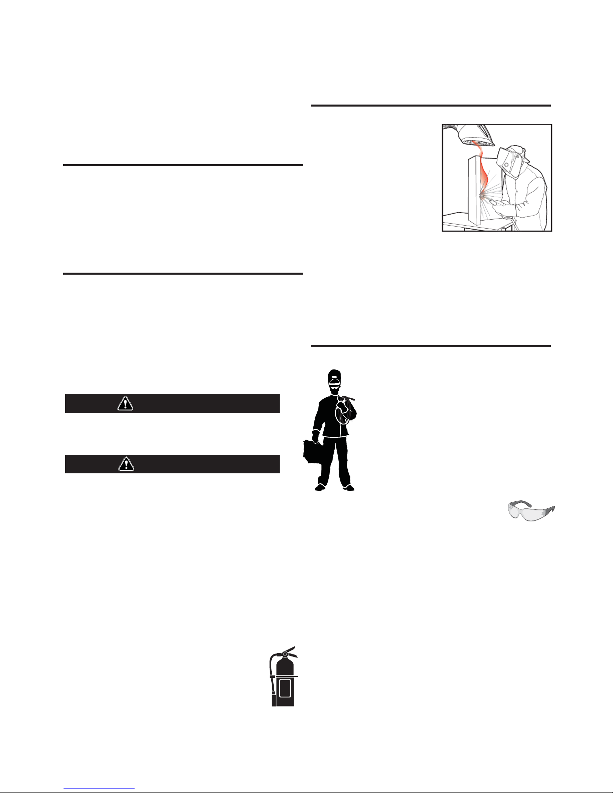
KEEP YOUR HEAD OUT OF THE FUMES.
DON’T get too close to the arc. Use
corrective lenses if necessary to
stay a reasonable distance away
from the arc.
READ and obey the Material Safety
Data Sheet (MSDS) and the warning
label that appears on all containers
of welding materials.
USE ENOUGH VENTILATION or
exhaust at the arc, or both, to keep
the fumes and gases from your breathing zone and the general area.
IN A LARGE ROOM OR OUTDOORS, natural ventilation may be
adequate if you keep your head out of the fumes (See below).
USE NATURAL DRAFTS or fans to keep the fumes away from your
face.
If you de velop unusual symptoms, see your supervisor. Perhaps the
welding atmosphere and ventilation system should be checked.
WEAR CORRECT EYE, EAR & BODY PROTECTION
PROTECT your eyes and face with welding helmet
properly fitted and with proper grade of filter plate
(See ANSI Z49.1).
PROTECT your body from welding spatter and arc
flash with protective clothing including woolen
clothing, flame-proof apron and gloves, leather
leggings, and high boots.
PROTECT others from splatter, flash, and glare with
protective screens or barriers.
IN SOME AREAS, protection from noise may be
appropriate.
BE SURE protective equipment is in good condition.
Also, wear safety glasses in work area
DO NOT WELD OR CUT containers or materials which previously had
been in contact with hazardous substances unless they are properly
cleaned. This is extremely dangerous.
DO NOT WELD OR CUT painted or plated parts unless special
precautions with ventilation have been taken. They can release highly
toxic fumes or gases.
PROTECT compressed gas cylinders from excessive heat, mechanical
shocks, and arcs; fasten cylinders so they cannot fall.
BE SURE cylinders are never grounded or part of an electrical circuit.
REMOVE all potential fire hazards from welding area.
ALWAYS HAVE FIRE FIGHTING EQUIPMENT READY FOR
IMMEDIATE USE AND KNOW HOW TO USE IT.
SECTION A:
WARNINGS
CALIFORNIA PROPOSITION 65 WARNINGS
Diesel Engines
Diesel engine exhaust and some of its constituents are known
to the State of California to cause cancer, birth defects, and other
reproductive harm.
Gasoline Engines
The engine exhaust from this product contains chemicals known
to the State of California to cause cancer, birth defects, or other
reproductive harm.
ARC WELDING CAN BE HAZARDOUS. PROTECT
YOURSELF AND OTHERS FROM POSSIBLE SERIOUS
INJURY OR DEATH. KEEP CHILDREN AWAY. PACEMAKER WEARERS SHOULD CONSULT WITH THEIR
DOCTOR BEFORE OPERATING.
Read and understand the following safety highlights. For additional
safety information, it is strongly recommended that you purchase a
copy of “Safety in Welding & Cutting - ANSI Standard Z49.1” from the
American Welding Society, P.O. Box 351040, Miami, Florida 33135 or
CSA Standard W117.2-1974. A Free copy of “Arc Welding Safety”
booklet E205 is available from the Lincoln Electric Company, 22801
St. Clair Avenue, Cleveland, Ohio 44117-1199.
BE SURE THAT ALL INSTALLATION, OPERATION,
MAINTENANCE AND REPAIR PROCEDURES ARE
PERFORMED ONLY BY QUALIFIED INDIVIDUALS.
SAFETY
1.d. Keep all equipment safety guards, covers and
devices in position and in good repair.Keep
hands, hair, clothing and tools away from
V-belts, gears, fans and all other moving parts
when starting, operating or repairing
equipment.
1.e. In some cases it may be necessary to remove safety guards to
perform required maintenance. Remove guards only when
necessary and replace them when the maintenance requiring
their removal is complete. Always use the greatest care when
working near moving parts.
1.f. Do not put your hands near the engine fan. Do not attempt to
override the governor or idler by pushing on the throttle control
rods while the engine is running.
1.g. To prevent accidentally starting gasoline engines while turning
the engine or welding generator during maintenance work,
disconnect the spark plug wires, distributor cap or magneto wire
as appropriate.
1.h. To avoid scalding, do not remove the radiator
pressure cap when the engine is
hot.
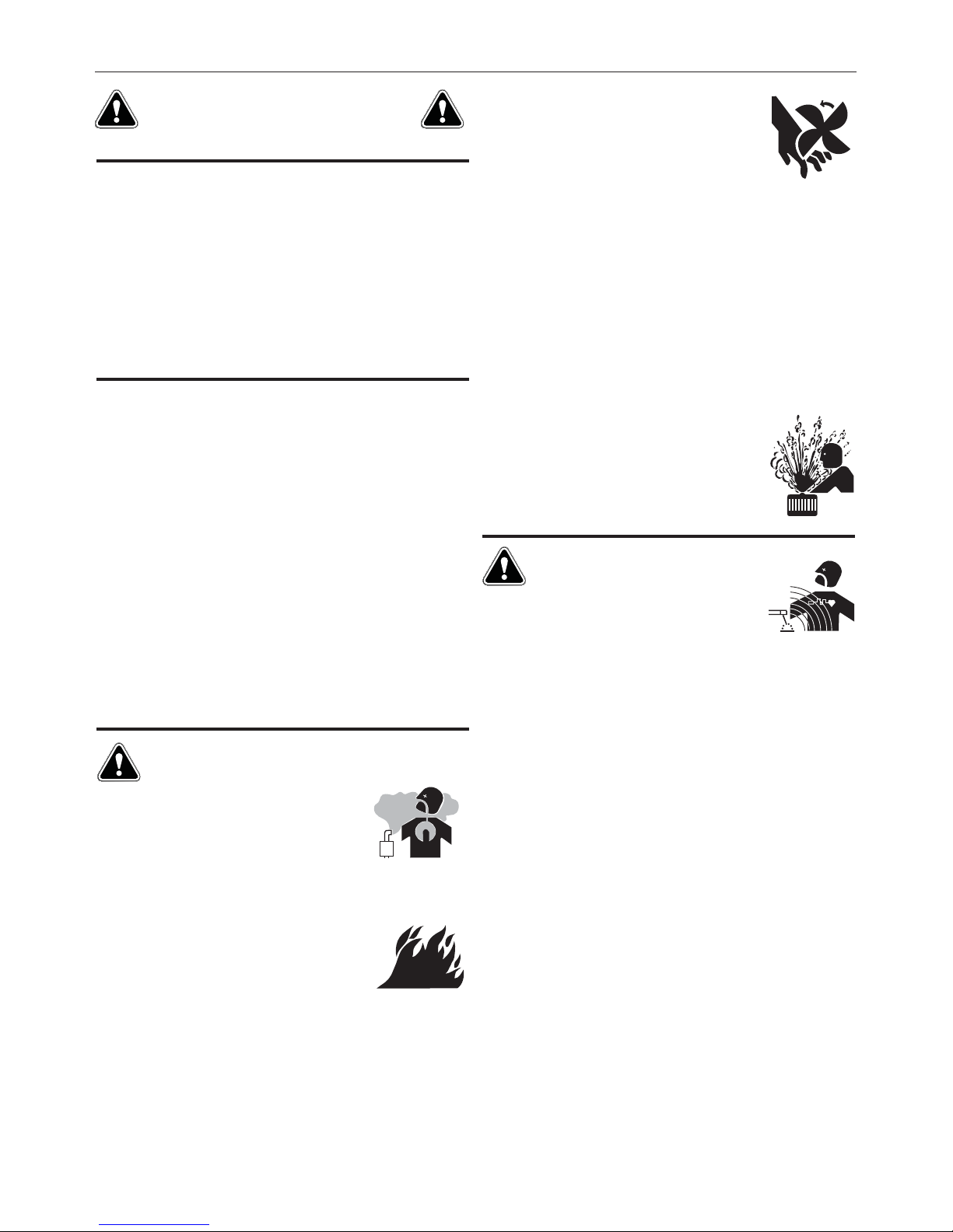
ELECTRIC AND
MAGNETIC FIELDS MAY
BE DANGEROUS
2.a. Electric current flowing through any conductor
causes localized Electric and Magnetic Fields (EMF). Welding
current creates EMF fields around welding cables and welding
machines
FOR ENGINE POWERED
EQUIPMENT.
1.a. Turn the engine off before troubleshooting
and maintenance work unless the
maintenance work requires it to be running.
1.b. Operate engines in open, well-ventilated
areas or vent the engine exhaust fumes outdoors.
1.c. Do not add the fuel near an open flame
welding arc or when the engine is running.
Stop the engine and allow it to cool before
refueling to prevent spilled fuel from
vaporizing on contact with hot engine parts
and igniting. Do not spill fuel when filling
tank. If fuel is spilled, wipe it up and do not start engine until
fumes have been eliminated.
2.b. EMF fields may interfere with some pacemakers, and welders
having a pacemaker should consult their physician before
welding.
2.c. Exposure to EMF fields in welding may have other health effects
which are now not known.
2.d. All welders should use the following procedures in order to
minimize exposure to EMF fields from the welding circuit:
2.d.1. Route the electrode and work cables together - Secure
them with tape when possible.
2.d.2. Never coil the electrode lead around your body.
2.d.3. Do not place your body between the electrode and work
cables. If the electrode cable is on your right side, the
work cable should also be on your right side.
2.d.4. Connect the work cable to the workpiece as close as possible to the area being welded.
2.d.5. Do not work next to welding power source.
3
SAFETY
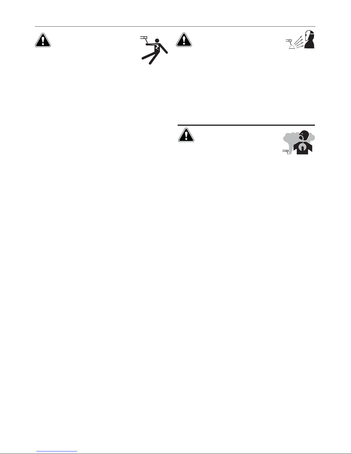
ELECTRIC SHOCK
CAN KILL.
3.a. The electrode and work (or ground) circuits are
electrically “hot” when the welder is on. Do
not touch these “hot” parts with your bare skin
or wet clothing. Wear dry, hole-free gloves to insulate hands.
3.b. Insulate yourself from work and ground using dry insulation.
Make certain the insulation is large enough to cover your full area
of physical contact with work and ground.
In addition to the normal safety precautions, if
welding must be performed under electrically
hazardous conditions (in damp locations or while
wearing wet clothing; on metal structures such as
floors, gratings or scaffolds; when in cramped
positions such as sitting, kneeling or lying, if there
is a high risk of unavoidable or accidental contact
with the workpiece or ground) use the following
equipment:
• Semiautomatic DC Constant Voltage (Wire) Welder.
• DC Manual (Stick) Welder.
• AC Welder with Reduced Voltage Control.
3.c. In semiautomatic or automatic wire welding, the electrode,
electrode reel, welding head, nozzle or semiautomatic welding
gun are also electrically “hot”.
3.d. Always be sure the work cable makes a good electrical
connection with the metal being welded. The connection should
be as close as possible to the area being welded.
3.e. Ground the work or metal to be welded to a good electrical (earth)
ground.
3.f. Maintain the electrode holder, work clamp, welding cable and
welding machine in good, safe operating condition. Replace
damaged insulation.
3.g. Never dip the electrode in water for cooling.
3.h. Never simultaneously touch electrically “hot” parts of electrode
holders connected to two welders because voltage
two can be the total of the open circuit voltage of both
welders.
3.i. When working above floor level, use a safety belt to protect
yourself from a fall should you get a shock.
between the
ARC RAYS CAN BURN.
4.a. Use a shield with the proper filter and cover plates to protect your
eyes from sparks and the rays of the arc when welding or
observing open arc welding. Headshield and filter lens should
conform to ANSI Z87. I standards.
4.b. Use suitable clothing made from durable flame-resistant material
to protect your skin and that of your helpers from the arc rays.
4.c. Protect other nearby personnel with suitable, non-flammable
screening and/or warn them not to watch the arc nor expose
themselves to the arc rays or to hot spatter or metal.
FUMES AND GASES
CAN BE DANGEROUS.
5.a. Welding may produce fumes and gases
hazardous to health. Avoid breathing these
fumes and gases. When welding, keep your head out of the fume.
Use enough ventilation and/or exhaust at the arc to keep fumes
and gases away from the breathing zone. When welding
with electrodes which require special ventilation
such as stainless or hard facing (see instructions
on container or MSDS) or on lead or cadmium
plated steel and other metals or coatings which
produce highly toxic fumes, keep exposure as low
as possible and within applicable OSHA PEL and
ACGIH TLV limits using local exhaust or
mechanical ventilation. In confined spaces or in
some circumstances, outdoors, a respirator may
be required. Additional precautions are also
required when welding on galvanized steel.
5. b. The operation of welding fume control equipment is affected by
various factors including proper use and positioning of the
equipment, maintenance of the equipment and the specific
welding procedure and application involved. Worker exposure
level should be checked upon installation and periodically
thereafter to be certain it is within applicable OSHA PEL and
ACGIH TLV limits.
5.c. Do not weld in locations near chlorinated hydrocarbon vapors
coming from degreasing, cleaning or spraying operations. The
heat and rays of the arc can react with solvent vapors to form
phosgene, a highly toxic gas, and other irritating products.
3.j. Also see It ems 6.c. and 8.
5.d. Shielding gases used for arc welding can displace air and
injury or death. Always use enough ventilation, especially in
confined areas, to insure breathing air is safe.
5.e. Read and understand the manufacturer’s instructions for this
equipment and the consumables to be used, including the
material safety data sheet (MSDS) and follow your employer’s
safety practices. MSDS forms are available from your welding
distributor or from the manufacturer.
5.f. Also see item 1.b.
4
cause
SAFETY
WELDING AND CUTTING
SPARKS CAN CAUSE
FIRE OR EXPLOSION.
6.a. Remove fire hazards from the welding area. If
this is not possible, cover them to prevent the
welding sparks from starting a fire. Remember that welding
sparks and hot materials from welding can easily go through
small cracks and openings to adjacent areas. Avoid welding near
hydraulic lines. Have a fire extinguisher readily available.
6.b. Where compressed gases are to be used at the job site, special
precautions should be used to prevent hazardous situations.
Refer to “Safety in Welding and Cutting” (ANSI Standard Z49.1)
and the operating information for the equipment being used.
6.c. When not welding, make certain no part of the electrode circuit is
touching the work or ground. Accidental contact can cause
overheating and create a fire hazard.
6.d. Do not heat, cut or weld tanks, drums or containers until the
proper steps have been taken to insure that such procedures will
not cause flammable or toxic vapors from substances inside.
They can cause an explosion even though they have been
“cleaned”. For information, purchase “Recommended Safe
Practices for the Preparation for Welding and Cutting of
Containers and Piping That Have Held Hazardous Substances”,
AWS F4.1 from the American Welding Society (see address
above).
6.e. Vent hollow castings or containers before heating, cutting or
welding. They may explode.
6.f. Sparks and spatter are thrown from the welding arc. Wear oil free
protective garments such as leather gloves, heavy shirt, cuffless
trousers, high shoes and a cap over your hair. Wear ear plugs
when welding out of position or in confined places. Always wear
safety glasses with side shields when in a welding area.
6.g. Connect the work cable to the work as close to the welding area
as practical. Work cables connected to the building framework or
other locations away from the welding area increase the
possibility of the welding current passing through lifting chains,
crane cables or other alternate circuits. This can create fire
hazards or overheat lifting chains or cables until they fail.
6.h. Also see item 1.c.
CYLINDER MAY EXPLODE IF
DAMAGED.
7.a. Use only compressed gas cylinders containing
the correct shielding gas for the process used
and properly operating regulators designed for
the gas and pressure used. All hoses, fittings,
etc. should be suitable for the application and
maintained in good condition.
7.b. Always keep cylinders in an upright position securely chained to
an undercarriage or fixed support.
7.c. Cylinders should be located:
• Away from areas where they may be struck or subjected
to physical damage.
• A safe distance from arc welding or cutting operations
and any other source of heat, sparks, or flame.
7.d. Never allow the electrode, electrode holder or any other
electrically “hot” parts to touch a cylinder.
7.e. Keep your head and face away from the cylinder valve outlet
when opening the cylinder valve.
7.f. Valve protection caps should always be in place and hand tight
except when the cylinder is in use or connected for use.
7.g. Read and follow the instructions on compressed gas cylinders,
associated equipment, and CGA publication P-l, “Precautions for
Safe Handling of Compressed Gases in
Cylinders,” available
from the Compressed Gas Association 1235 Jefferson Davis
Highway, Arlington, VA 22202.
FOR ELECTRICALLY
POWERED EQUIPMENT.
8.a. Turn off input power using the disconnect
switch at the fuse box before working on the
equipment.
8.b. Install equipment in accordance with the U.S. National Electrical
Code, all local codes and the manufacturer’s recommendations.
6.I. Read and follow NFPA 51B “ Standard for Fire Prevention During
Welding, Cutting and Other Hot Work”, available from NFPA, 1
Batterymarch Park, PO box 9101, Quincy, Ma 022690-9101.
6.j. Do not use a welding power source for pipe thawing.
8.c. Ground the equipment in accordance with the U.S. National
Electrical Code and the manufacturer’s recommendations.
Refer to
http://www.lincolnelectric.com/safety
for additional safety information.
Welding Safety
Interactive Web Guide
for mobile devices
5

vi
TABLE OF CONTENTS
Page
Installation.......................................................................................................................Section A
Technical Specifications.......................................................................................................A-1
Safety Precautions ........................................................................................................A-2
Machine Grounding.......................................................................................................A-2
Spark Arrester ...............................................................................................................A-2
Towing...........................................................................................................................A-2
Vehicle Mounting...........................................................................................................A-3
Pre-Operation Engine Service..............................................................................................A-3
Fuel, Oil, Battery Connections ......................................................................................A-3
Welding Cable Connections..........................................................................................A-4
Angle of Operation ........................................................................................................A-4
Lifting, Additional Safety Precautions............................................................................A-4
High Altitude Operation .................................................................................................A-4
Muffler Outlet Pipe ........................................................................................................A-4
Location and Ventilation................................................................................................A-5
Stacking ........................................................................................................................A-5
Connection of Wire Feeders .........................................................................................A-5
Connection of Tig Module .............................................................................................A-5
Additional Safety Precautions .......................................................................................A-5
Welding Operation Output, Auxiliary Power Receptacles, and Plugs .................................A-6
Motor Starting and Extension Cord Length Table ................................................................A-6
Electrical Device Used with the Ranger 250 GXT (AU) .......................................................A-7
Auxiliary Power While Welding, Standby Power Connections ............................................A-8
________________________________________________________________________________
Operation.........................................................................................................................Section B
Safety Precautions ...............................................................................................................B-1
General Description..............................................................................................................B-1
Welder Controls Function and Operation .............................................................................B-1
Polarity, Range and Control Switch......................................................................................B-2
Start in/Shutdown Instructions.....................................................................................................B-3
Starting the Engine........................................................................................................B-3
Safety Precautions ........................................................................................................B-3
Stopping the Engine......................................................................................................B-3
Break-In Period .............................................................................................................B-3
Welding Process ..................................................................................................................B-4
Stick (Constant Current) Welding..................................................................................B-4
TIG (Constant Current) Welding ..................................................................................B-4
Wire Feed Welding Processes (Constant Voltage)......................................................B-4
Arc Gouging ..................................................................................................................B-4
Summary of Welding Processes ...................................................................................B-5
________________________________________________________________________________
Accessories ........................................................................................................Section C
Optional Equipment...............................................................................................C-1
Recommended Equipment....................................................................................C-2
________________________________________________________________________
Maintenance ....................................................................................................Section D
Safety Precautions ................................................................................................D-1
Routine Engine Maintenance ..........................................................................D-1,D2
Engine Adjustments...............................................................................................D-3
Slip Rings ..............................................................................................................D-3
Battery Maintenance .......................................................................................D-3
Engine Maintenance Parts..............................................................................D-3
________________________________________________________________________
Troubleshooting..............................................................................................Section E
How to Use Troubleshooting Guide.......................................................................E-1
Troubleshooting Guide...................................................................................E-2, E-3
________________________________________________________________________
Wiring Diagrams, Connection Diagrams & Dimension Print.......................Section F
________________________________________________________________________
Parts List.................................................................................................... P-645 Series
________________________________________________________________________
vi
A-1
INSTALLATION
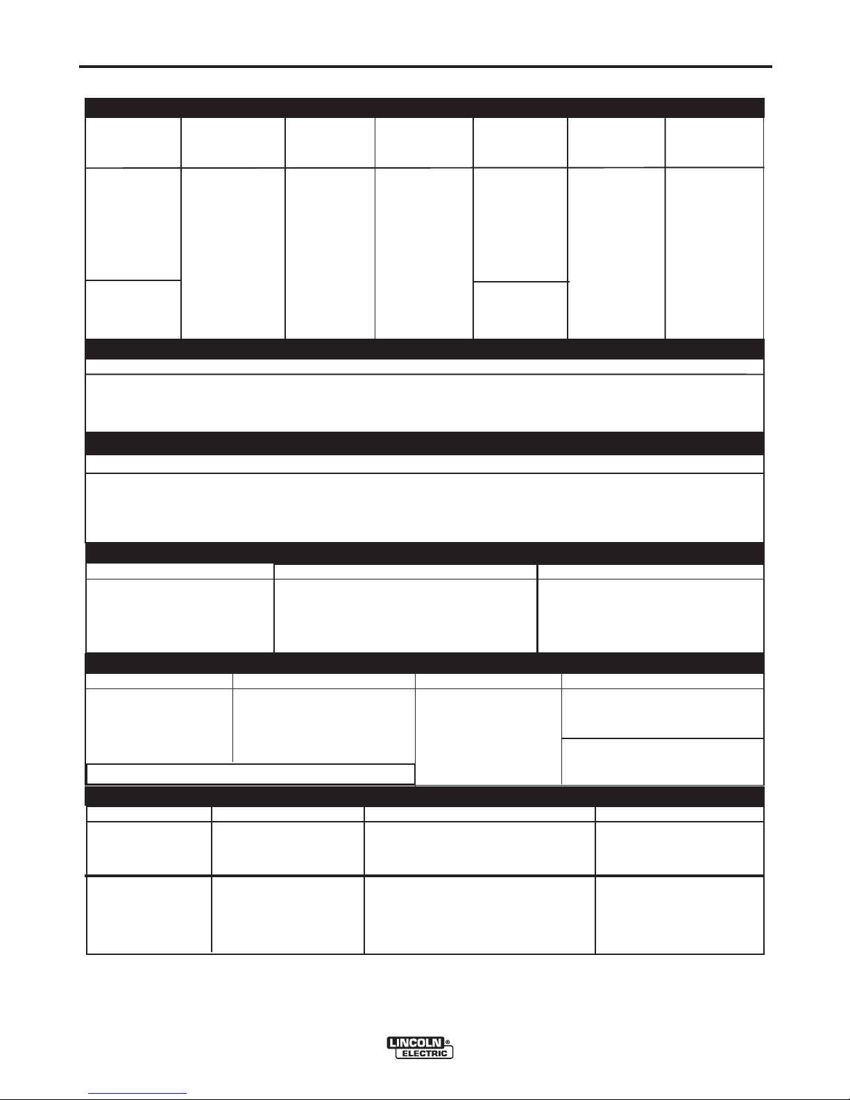
TECHNICAL SPECIFICATIONS - Ranger® 250 GXT (AU) ( K2923-1)
INPUT - GASOLINE ENGINE
Make/Model
Kohler
CH23S,
CH680
CH730
Description
2 cylinder
4 Cycle
Air-Cooled
Gasoline
Engine.
Aluminum Alloy
with Cast Iron
Liners,
Electronic
Ignition
RATED OUTPUT @ 104°F (40°C)- WELDER
RATED OUTPUT @ 104°F (40°C)- GENERATOR
Horsepower
23 HP @
3600 RPM
AC Constant Current 250A / 25V / 100%
DC Constant Current 250A / 25V / 100%
DC Constant Voltage 250A / 25V / 100%
Operating
Speed (RPM)
High Idle 3700
Full Load 3500
Low Idle 2200
Welding Output
Auxiliary Power
Displacement
cu. in.
(cu.cm.)
41.1(674)
44.2(724)
1
Starting
System
12VDC
Battery
Electric Start
Group 58
Battery
(435 cold
Cranking
Amps)
A-1
Capacities
Fuel:
12 Gal (45.4 L)
Lubricating Oil:
2.0 Qts. (1.9 L)
7,200 Watts Continuous, 60 Hz AC
240 Volts
RECEPTACLES AND CIRCUIT BREAKERS
RECEPTACLES
(2) 240VAC Receptacles
AUXILIARY POWER CIRCUIT BREAKER
Two 15AMP for Two Receptacles
BATTERY CHARGING CIRCUIT BREAKER
20AMP for Engine Battery
Charging Circuit
PHYSICAL DIMENSIONS
HEIGHT WIDTH DEPTH WEIGHT
Codes 11803 and below
30.00** in. 21.50 in 42.25 in.
762.0 mm 546.0 mm 1073.0 mm
** Top of enclosure, add 6.00”(152mm) for exhaust.
567 lbs. (257kg.)
Code 12099
574 lbs. (260kg.)
ENGINE COMPONENTS
LUBRICATION VALVE LIFTERS FUEL SYSTEM GOVERNOR
Full Pressure Hydraulic Electric fuel lift pump. Mechanical Governor
with Full Flow Filter
5% Regulation
AIR CLEANER ENGINE IDLER MUFFLER ENGINE PROTECTION
Low noise Muffler: Top outlet Shutdown on low oil
Dual Element Automatic Idler can be rotated. Made from pressure.
long life, aluminized steel.
1
Output rating in watts is equivalent to volt - amperes at unity factor.Output voltage is within +/-10% at all loads up to rated capacity.
When welding available auxiliary power will be reduced.
RANGER® 250 GXT (AU)
A-2
INSTALLATION
A-2
SAFETY PRECAUTIONS
WARNING
Do not attempt to use this equipment until you
have thoroughly read the engine manufacturerʼs
manual supplied with your welder. It includes
important safety precautions, detailed engine
starting, operating and maintenance instructions,
and parts lists.
------------------------------------------------------------------------
ELECTRIC SHOCK can kill.
• Do not touch electrically live parts or
electrode with skin or wet clothing.
• Insulate yourself from work and
ground
• Always wear dry insulating gloves.
------------------------------------------------------------------------
ENGINE EXHAUST can kill.
• Use in open, well ventilated areas or
vent exhaust outside.
------------------------------------------------------------------------
MOVING PARTS can injure.
• Do not operate with doors open or
guards off.
• Stop engine before servicing.
• Keep away from moving parts.
------------------------------------------------------------------------
When this welder is mounted on a truck or trailer, itʼs
frame must be electrically bonded to the metal frame
of the vehicle. Use a #8 or larger copper wire connected between the machine grounding stud and the
frame of the vehicle.
Where this engine driven welder is connected to
premises wiring such as that in your home or shop, itʼs
frame must be connected to the system earth ground.
See further connection instructions in the section entitled “Standby Power Connections”, as well as the article on grounding in the latest National Electrical Code
and the local code.
In general, if the machine is to be grounded, it should
be connected with a #8 or larger copper wire to a solid
earth ground such as a metal water pipe going into
the ground for at least ten feet and having no insulated joints, or to the metal framework of a building
which has been effectively grounded. The National
Electrical Code lists a number of alternate means of
grounding electrical equipment. A machine grounding
stud marked with the symbol is provided on the
front of the welder.
SPARK ARRESTER
See additional warning information at
front of this operatorʼs manual.
-----------------------------------------------------------
MACHINE GROUNDING
Because this portable engine driven welder or generator creates itʼs own power, it is not necessary to connect itʼs frame to an earth ground, unless the machine
is connected to premises wiring (your home, shop,
etc.).
WARNING
To prevent dangerous electric shock, other equipment to which this engine driven welder supplies
power must:
• be grounded to the frame of the welder using a
grounded type plug, or be double insulated.
Do not ground the machine to a pipe that carries
explosive or combustible material.
------------------------------------------------------------------------
Some federal, state, or local laws may require that
gasoline engines be equipped with exhaust spark
arresters when they are operated in certain locations
where unarrested sparks may present a fire hazard.
The standard muffler included with this welder does
not qualify as a spark arrester. When required by local
regulations, the K1898-1 spark arrester must be
installed and properly maintained.
CAUTION
An incorrect arrester may lead to damage to the
engine or adversely affect performance.
------------------------------------------------------------------------
TOWING
The recommended trailer for use with this equipment
for road, in-plant and yard towing by a vehicle
Lincolnʼs K957-1. If the user adapts a non-Lincoln
trailer, he must assume responsibility that the method
of attachment and usage does not result in a safety
hazard nor damage the welding equipment. Some of
the factors to be considered are as follows:
1. Design capacity of trailer vs. weight of Lincoln
equipment and likely additional attachments.
(1)
is
2. Proper support of, and attachment to, the base of
the welding equipment so there will be no undue
stress to the framework.
RANGER® 250 GXT (AU)
A-3
3. Proper placement of the equipment on the trailer to
insure stability side to side and front to back when
being moved and when standing by itself while
being operated or serviced.
4. Typical conditions of use, i.e., travel speed; rough-
ness of surface on which the trailer will be operated;
environmental conditions.
5. Conformance with federal, state and local laws
(1) Consult applicable federal, state and local laws regarding specific
requirements for use on public highways.
VEHICLE MOUNTING
INSTALLATION
(1)
WARNING
Improperly mounted concentrated loads may
cause unstable vehicle handling and tires or other
components to fail.
• Only transport this Equipment on serviceable
vehicles which are rated and designed for such
loads.
• Distribute, balance and secure loads so vehicle
is stable under conditions of use.
• Do not exceed maximum rated loads for components such as suspension, axles and tires.
• Mount equipment base to metal bed or frame of
vehicle.
• Follow vehicle manufacturerʼs instructions.
------------------------------------------------------------------------
PRE-OPERATION SERVICE
CAUTION
READ the engine operating and maintenance
instructions supplied with this machine.
A-3
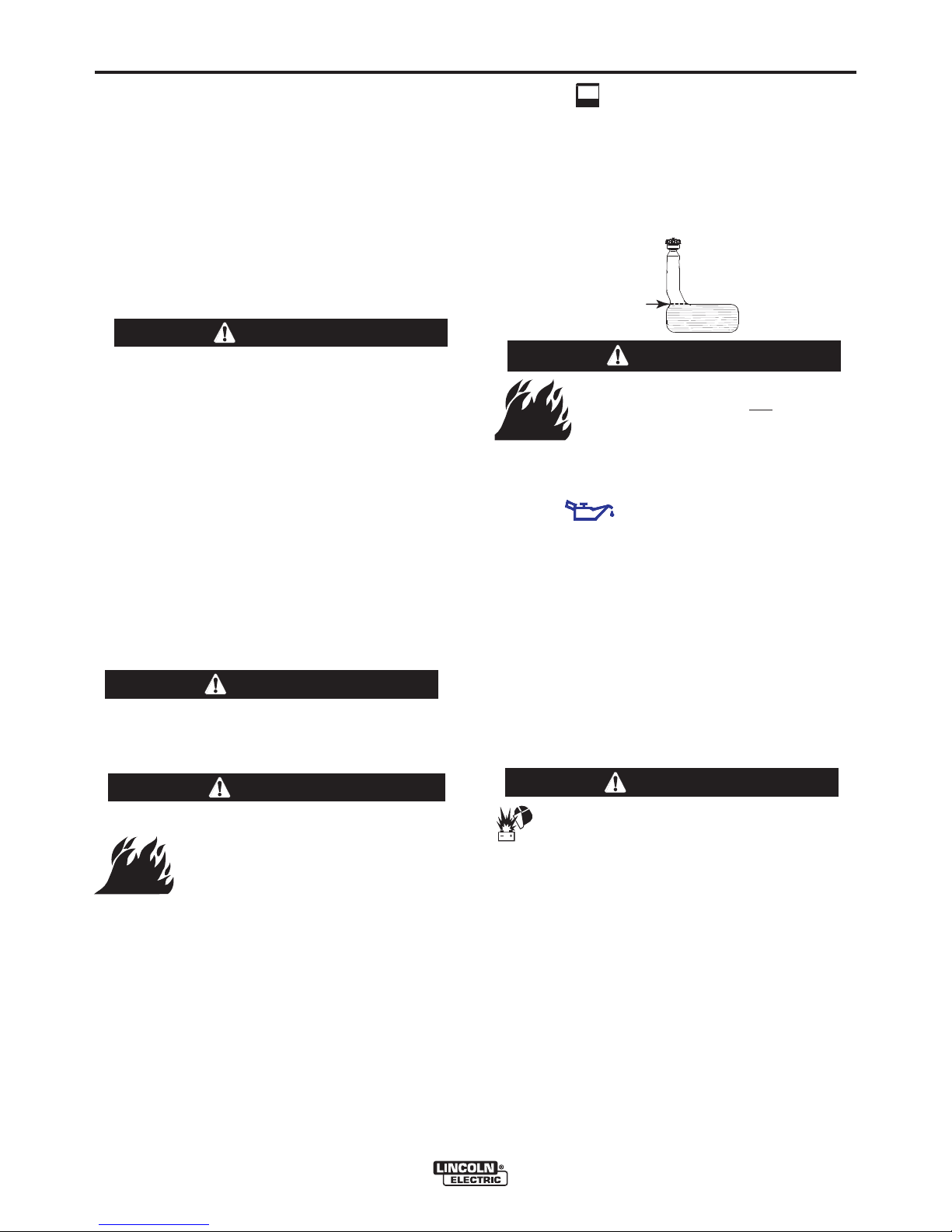
FUEL
Fill the fuel tank with clean, fresh, lead-free gasoline.
Observe fuel gauge while filling to prevent overfilling.
Stop fueling once the fuel gauge reads full. Do not top
off tank. Be sure to leave filler neck empty to allow
room for expansion.
FULL
WARNING
• Damage to the fuel tank may cause
fire or explosion. Do not
in the RANGER
weld to the RANGER
-----------------------------------------------------------------------
OIL
LUBRICATION SYSTEM CAPACITY
Kohler CH23S, CH680, CH730 - 2.0 Quarts (1.9 Liters)
The RANGER
crankcase filled with SAE 10W-30 oil. Check the oil
level before starting the engine. If it is not up to the full
mark on the dip stick, add oil as required. Make certain that the oil filler cap is tightened securely. Refer to
the engine Ownerʼs Manual for specific oil recommendations.
base.
(INCLUDING FILTER)
®
GXT (AU) is shipped with the engine
®
GXT (AU) base or
drill holes
®
GXT (AU)
WARNING
• Stop engine while fueling.
• Do not smoke when fueling.
• Keep sparks and flame away
from tank.
• Do not leave unattended while
fueling.
• Wipe up spilled fuel and allow
GASOLINE
can cause fire
or explosion.
fumes to clear before starting
engine.
• Do not overfill tank, fuel expansion may cause overflow.
GASOLINE FUEL ONLY
------------------------------------------------------------------------
CAUTION
BATTERY CONNECTIONS
Use caution as the electrolyte is a strong acid that
can burn skin and damage eyes.
------------------------------------------------------------------------
This welder is shipped with the negative battery cable
disconnected. Make sure that the Engine Switch is in
the “STOP” position and attach the disconnected
cable securely to the negative battery terminal before
attempting to operate the machine. If the battery is
discharged and does not have enough power to start
the engine, see the battery charging instructions in the
Battery section.
NOTE: This machine is furnished with a wet charged
battery; if unused for several months, the battery may
require a booster charge. Be careful to charge the battery with the correct polarity.
RANGER® 250 GXT (AU)
A-4
INSTALLATION
WELDING OUTPUT CABLES
With the engine off, connect the electrode and work
cables to the studs provided. These connections
should be checked periodically and tightened if necessary. Loose connections will result in overheating of
the output studs.
When welding at a considerable distance from the
welder, be sure you use ample size welding cables.
Listed below are copper cable sizes recommended for
the rated current and duty cycle. Lengths stipulated
are the distance from the welder to work and back to
the welder again. Cable sizes are increased for
greater lengths primarily for the purpose of minimizing
cable voltage drop.
TOTAL COMBINED LENGTH OF
ELECTRODE AND WORK CABLES
250 Amps
100% Duty Cycle
0-100 Ft. (0-31m)
100-150 Ft. (31-46m)
150-200 Ft. (46-61m)
1 AWG
1 AWG
1/0 AWG
ANGLE OF OPERATION
Internal combustion engines are designed to run in a
level condition which is where the optimum performance is achieved. The maximum angle of operation
for the engine is 15 degrees from horizontal in any
direction. If the engine is to be operated at an angle,
provisions must be made for checking and maintaining the oil at the normal (FULL) oil capacity in the
crankcase in a level condition.
When operating at an angle, the effective fuel capacity
will be slightly less than the specified 12 Gal. (45 L).
A-4
ADDITIONAL SAFETY PRECAUTION
WARNING
• Lift only with equipment of
adequate lifting capacity.
• Be sure machine is stable
when lifting.
• Do not lift this machine using
lift bail if it is equipped with a
heavy accessory such as trailer or gas cylinder.
FALLING • Do not lift machine if lift bail is
EQUIPMENT can damaged.
cause injury. • Do not operate machine while
suspended from lift bail.
------------------------------------------------------------------------
HIGH ALTITUDE OPERATION
At higher altitudes, Welder output de-rating may be
necessary. For maximum rating, de-rate the welder
output 3.5% for every 1000 ft. (305m) above 3000 ft.
(914m). If operation will consistently be at altitudes
above 5,000 ft. (1525m), a carburetor jet designed for
high altitudes should be installed. This will result in
better fuel economy, cleaner exhaust and longer
spark plug life. It will not give increased power.
Contact your local authorized engine service shop for
high altitude jet kits that are available from the engine
manufacturer.
CAUTION
Do not operate with a high altitude jet installed at
altitudes below 5000 ft. This will result in the
engine running too lean and result in higher
engine operating temperatures which can shorten
engine life.
------------------------------------------------------------------------
MUFFLER OUTLET PIPE
LIFTING
The Ranger® 250 GXT (AU) weighs approximately
646lbs.(293kg) with a full tank of gasoline. A lift bail is
mounted to the machine and should always be used
when lifting the machine.
Using the clamp provided secure the outlet pipe to the
outlet tube with the pipe positioned such that it will
direct the exhaust in the desired direction. Tighten
using a 9/16” socket or wrench.
RANGER® 250 GXT (AU)

A-5
INSTALLATION
LOCATION / VENTILATION
The welder should be located to provide an unrestricted flow of clean, cool air to the cooling air inlets and to
avoid heated air coming out of the welder recirculating
back to the cooling air inlet. Also, locate the welder so
that engine exhaust fumes are properly vented to an
outside area.
STACKING
Ranger® 250 GXT (AU) machines cannot be stacked.
CONNECTION OF LINCOLN ELECTRIC
WIRE FEEDERS
WARNING
Shut off welder before making any electrical
connections.
-----------------------------------------------------------------------
WIRE FEED (CONSTANT VOLTAGE)
CONNECTION OF LN-15 ACROSS-THE-ARC WIRE
FEEDER
The LN-15 has an internal contactor and the electrode
is not energized until the gun trigger is closed. When
the gun trigger is closed the wire will begin to feed and
the welding process is started.
• Shut the welder off.
Connect the electrode cable from the LN-15 to
•
“ELECTRODE” terminal of the welder. Connect
the
the work cable to the “TO WORK” terminal of the
welder.
• Set the Polarity switch to the desired polarity, either
DC (-) or DC (+).
• Attach the single lead from the front of the LN-15
to work using the spring clip at the end of the lead.
This is a control lead to supply current to the wire
feeder motor; it does not carry welding current.
• Set the “RANGE” switch to the “WIRE FEED-CV”
position
• Place the Engine switch in the “Auto Idle” position
when welding with MIG wire instead of self-shielded
core wire, weld starts can be improved by setting
the idle mode to “HIGH”.
• Adjust the wire feed speed at the LN-15 and adjust
the welding voltage with the output “CONTROL” at
the welder.
when welding with MIG wire instead of self-shielded
core wire, weld starts can be improved by setting
the idle mode to “HIGH”
Note: LN-15 Control Cable model will not work with
Output “CONTROL” must be set above 3
.
the Ranger® 250 GXT (AU).
A-5
• Position the “RANGE” switch to the “WIRE FEED
CV” position.
• Attach the single lead from the LN-25 control box
to the work using the spring clip on the end of the
lead - it carries no welding current.
• Place the engine switch in the “AUTO IDLE” position.
• When welding with MIG wire instead of selfshielded core wire, weld starts can be improved
by setting the idle mode to “HIGH”
• Adjust wire feed speed at the LN-25 and adjust
the welding voltage with the output “CONTROL”
at the welder.
NOTE: The welding electrode is energized at all
times, unless an LN-25 with built-in contactor is used.
If the output “CONTROL” is set below “3”, the LN-25
contactor may not pull in.
CONNECTION OF THE LN-25 TO THE
250 GXT (AU)
• Shut the welder off.
Connect the electrode cable from the LN-25 to
•
“ELECTRODE” terminal of the welder.
the
Connect the work cable to the “TO WORK” terminal of the welder.
• Position the welder “Polarity” switch to the desired
polarity, either DC (-) or DC (+).
CONNECTION OF K930-2 TIG MODULE TO THE
RANGER® 250 GXT (AU).
The TIG Module is an accessory that provides high
frequency and shielding gas control for AC and DC
GTAW (TIG) welding. See IM528 supplied with the
TIG Module for installation instructions.
Note: The TIG Module does not require the use of a
high frequency bypass capacitor. However, if the
Ranger® 250 GXT (AU) is used with any other high
frequency equipment, the bypass capacitor must be
installed, order kit T12246.
.
RANGER®
INSTRUCTIONS
ADDITIONAL SAFETY PRECAUTIONS
Always operate the welder with the roof and case
sides in place as this provides maximum protection
from moving parts and assures proper cooling air flow.
Read and understand all Safety Precautions before
operating this machine. Always follow these and any
other safety procedures included in this manual and in
the Engine Ownerʼs Manual.
RANGER® 250 GXT (AU)
 Loading...