

Lincoln Electric PRO-CUT 55 SVM140-A, PRO-CUT 55 Service Manual

SVM140-A
July, 2005
Safety Depends on You
Lincoln arc welding and cutting
equipment is designed and built
with safety in mind. However,
your overall safety can be
increased by proper installation
. . . and thoughtful operation on
your part. DO NOT INSTALL,
OPERATE OR REPAIR THIS
EQUIPMENT WITHOUT READING THIS MANUAL AND THE
SAFETY PRECAUTIONS CONTAINED THROUGHOUT. And,
most importantly, think before
you act and be careful.
For use with machine code numbers Below 11000
PRO-CUT ™55
Return to Master TOC Return to Master TOC Return to Master TOC Return to Master TOC
View Safety Info View Safety Info View Safety Info View Safety Info
SERVICE MANUAL
• Sales and Service through Subsidiaries and Distributors Worldwide •
Cleveland, Ohio 44117-1199 U.S.A. TEL: 216.481.8100 FAX: 216.486.1751 WEB SITE: www.lincolnelectric.com
• World's Leader in Welding and Cutting Products •
Copyright © 2005 Lincoln Global Inc.
Return to Master TOC Return to Master TOC Return to Master TOC Return to Master TOC
PRO-CUT 55
i
SAFETY
i
PROTECT YOURSELF AND OTHERS FROM POSSIBLE SERIOUS INJURY OR DEATH. KEEP CHILDREN
AWAY. PACEMAKER WEARERS SHOULD CONSULT WITH THEIR DOCTOR BEFORE OPERATING.
Read and understand the following safety highlights. For additional safety information it is strongly recommended that you purchase a copy of “Safety in Welding & Cutting - ANSIStandard Z49.1” from the American Welding Society, P.O. Box 351040,
Miami, Florida 33135 or CSA Standard W117.2.
BE SURE THAT ALL INSTALLATION, OPERATION, MAINTENANCE, AND REPAIR PROCEDURES ARE
PERFORMED ONLY BY QUALIFIED INDIVIDUALS.
CUTTING SPARKS can
cause fire or explosion.
4.a. Remove fire hazards from the plasma cutting
or gouging area. If this is not possible, cover them
to prevent the cutting or gouging sparks from
starting a fire. Remember that welding sparks
and hot materials from plasma cutting or gouging
can easily go through small cracks and openings to adjacent
areas. Avoid cutting or gouging near hydraulic lines. Have a
fire extinguisher readily available.
4.b. Where compressed gases are to be used at the job site, special precautions should be used to prevent hazardous situations. Refer to “Safety in Welding and Cutting” (ANSI Standard
Z49.1) and the operating information for the equipment being
used.
4.c. When not cutting or gouging, make certain no part of the electrode circuit is touching the work or ground. Accidental contact
can cause overheating and create a fire hazard.
4.d. Do not cut or gouge tanks, drums or containers until the proper steps have been taken to insure that such procedures will
not cause flammable or toxic vapors from substances inside.
They can cause an explosion even though they have been
“cleaned.” For information purchase “Recommended Safe
Practices for the Preparation for Welding and Cutting of
Containers and Piping That Have Held Hazardous
Substances”, AWS F4.1 from the American Welding Society
(see address above).
4.e. Vent hollow castings or containers before heating, cutting or
gouging. They may explode.
4.f. Do nor fuel engine driven equipment near area where plasma
cutting or gouging.
ARC RAYS can burn.
2.a. Use safety glasses and a shield with the proper filter and cover plates to protect your eyes from
sparks and the rays of the arc when performing or
observing plasma arc cutting or gouging.
Glasses,headshield and filter lens should conform
to ANSI Z87. I standards.
2.b. Use suitable clothing including gloves made from durable
flame-resistant material to protect your skin and that of your
helpers from the arc rays.
2.c. Protect other nearby personnel with suitable non-flammable
screening and/or warn them not to watch the arc nor expose
themselves to the arc rays or to hot spatter or metal.
ELECTRIC SHOCK can kill.
1.a. The electrode and work (or ground) circuits
are electrically “hot” when the power source is on.
Do not touch these “hot” parts with your bare skin
or wet clothing. Wear dry, hole-free gloves to insulate hands.
1.b. When the power source is operating voltages in excess of 250
volts are produced. This creates the potential for serious electrical shock - potentially even fatal.
1.c. Insulate yourself from work and ground using dry insulation.
When cutting or gouging in damp locations, on metal framework such as floors, gratings or scaffolds and when in positions such as sitting or lying, make certain the insulation is
large enough to cover your full area of physical contact with
work and ground.
1.d. Always be sure the work cable makes a good electrical connection with the metal being cut or gouged. The connection
should be as close as possible to the area being cut or
gouged.
1.e. Ground the work or metal to be cut or gouged to a good electrical (earth) ground.
1.f. Maintain the plasma torch, cable and work clamp in good, safe
operating condition. Replace damaged insulation.
1.g. Never dip the torch in water for cooling or plasma cut or gouge
in or under water.
1.h. When working above floor level, protect yourself from a fall
should you get a shock.
1.i. Operate the pilot arc with caution. The pilot arc is capable of
burning the operator, others or even piercing safety clothing.
1.j. Also see Items 4c and 6.
WARNING
PLASMA CUTTING or GOUGING can be hazardous.
FUMES AND GASES
can be dangerous.
3.a. Plasma cutting or gouging may produce
fumes and gases hazardous to health. Avoid
breathing these fumes and gases.When cutting
or gouging, keep your head out of the fumes. Use
enough ventilation and/or exhaust at the arc to
keep fumes and gases away from the breathing
zone. When cutting or gouging on lead or cadmium plat-
ed steel and other metals or coatings which produce
highly toxic fumes keep exposure as low as possible and
below Threshold Limit Values (TLV) using local exhaust
or mechanical ventilation. In confined spaces or in some
circumstances, outdoors, a respirator may be required.
Additional precautions are also required when welding
on galvanized steel.
3.b. Do not use plasma arc cutting or gouging in locations near
chlorinated hydrocarbon vapors coming from degreasing,
cleaning or spraying operations. The heat and rays of the arc
can react with solvent vapors to form phosgene, a highly toxic
gas, and other irritating products.
3.c. Gases used for plasma cutting and gouging can displace air
and cause injury or death. Always use enough ventilation,
especially in confined areas, to insure breathing air is safe.
3.d. Read and understand the manufacturer’s instructions for this
equipment and the consumables to be used, including the
material safety data sheet (MSDS) and follow your employer’s safety practices.
Return to Master TOC Return to Master TOC Return to Master TOC Return to Master TOC
SAFETY
ii ii
PRO-CUT 55
FOR ELECTRICALLY
powered equipment.
6.a. Turn off input power using the disconnect
switch at the fuse box before working on the
equipment.
6.b. Install equipment in accordance with the U.S. National
Electrical Code, all local codes and the manufacturer’s recommendations.
6.c. Ground the equipment in accordance with the U.S. National
Electrical Code and the manufacturer’s recommendations.
CYLINDER may explode
if damaged.
5.a. Use only compressed gas cylinders containing the correct gas for the process used and
properly operating regulators designed for the
gas and pressure used. All hoses, fittings, etc.
should be suitable for the application and maintained in good
condition.
5.b. Always keep cylinders in an upright position securely chained
to an undercarriage or fixed support.
5.c. Cylinders should be located:
• Away from areas where they may be struck or subjected to
physical damage.
• Asafe distance from plasma cutting or gouging, arc weld-
ing operations and any other source of heat, sparks,
or flame.
5.d. Never allow any part of the electrode, torch or any other electrically “hot” parts to touch a cylinder.
5.e. Keep your head and face away from the cylinder valve outlet
when opening the cylinder valve.
5.f. Valve protection caps should always be in place and hand
tight except when the cylinder is in use or connected for use.
5.g. Read and follow the instructions on compressed gas cylinders, associated equipment, and CGA publication P-l,
“Precautions for Safe Handling of Compressed Gases in
Cylinders,”available from the Compressed Gas Association
1235 Jefferson Davis Highway, Arlington, VA 22202.
Apr. ‘93
ELECTRIC AND MAGNETIC FIELDS
may be dangerous
8.a. Electric current flowing through any conductor causes localized Electric and Magnetic Fields
(EMF). Cutting or gouging current creates EMF
fields around torch cables and cutting machines.
8.b. EMF fields may interfere with some pacemakers, so operators having a pacemaker should consult
their physician before cutting or gouging.
8.c. Exposure to EMF fields during cutting or gouging may have
other health effects which are now not known.
8d. All operators should use the following procedures in order to
minimize exposure to EMF fields from the cutting or gouging
circuit:
8.d.1. Route the torch and work cables together - Secure
them with tape when possible.
8.d.2. Never coil the torch cable around your body.
8.d.3. Do not place your body between the torch and
work cables. If the torch cable is on your right side,
the work cable should also be on your right
side.
8.d.4. Connect the work cable to the workpiece as close as
possible to the area being cut or gouged.
8.d.5. Do not work next to cutting power source.
4.g. Sparks and spatter are thrown from the plasma arc. Wear safety glasses, ear protection and oil free protective garments such
as leather gloves, heavy shirt, cuffless trousers, high shoes
and a cap over your hair. Wear ear plugs when cutting or gouging out of position or in confined places. Always wear safety
glasses with side shields when in a cutting or gouging area.
4.h. Connect the work cable to the work as close to the cutting or
gouging area as practical. Work cables connected to the building framework or other locations away from the cutting or gouging area increase the possibility of the current passing through
lifting chains, crane cables or other alternate circuits. This can
create fire hazards or overheat lifting chains or cables until they
fail.
PLASMA ARC can injure.
7.a. Keep your body away from nozzle and
plasma arc.
7.b. Operate the pilot arc with caution. The pilot arc is capable of
burning the operator, others or even piercing safety clothing.

Return to Master TOC Return to Master TOC Return to Master TOC Return to Master TOC
NOTES
iii iii
PRO-CUT 55

MASTER TABLE OF CONTENTS FOR ALL SECTIONS
iv iv
PRO-CUT 55
Page
Safety.................................................................................................................................................i-iii
Installation.............................................................................................................................Section A
Operation...............................................................................................................................Section B
Accessories...........................................................................................................................Section C
Maintenance .........................................................................................................................Section D
Theory of Operation .............................................................................................................Section E
Troubleshooting and Repair.................................................................................................Section F
Safety Precautions ......................................................................................................................F-2
How to Use Troubleshooting Guide............................................................................................F-2
Troubleshooting Guide ................................................................................................................F-4
Test Procedures ........................................................................................................................F-14
Replacement Procedures .........................................................................................................F-50
Electrical Diagrams..............................................................................................................Section G
Parts Manual ....................................................................................................P309 Series & P210-K

Return to Master TOC Return to Master TOC Return to Master TOC Return to Master TOC
TABLE OF CONTENTS
- INSTALLATION SECTION -
Section A-1 Section A-1
PRO-CUT 55
Installation
Technical Specifications .............................................................................................................A-2
Safety Precautions......................................................................................................................A-4
Select Suitable Location.............................................................................................................A-4
Stacking......................................................................................................................................A-4
Lifting and Moving ......................................................................................................................A-4
Tilting ..........................................................................................................................................A-4
High Frequency Interference Protection.....................................................................................A-4
Input Electrical Connections.......................................................................................................A-5
Ground Connection ..............................................................................................................A-5
Input Power Cord Connector Installation...................................................................................A-5
Input Wire and Fuse Size .....................................................................................................A-5
Reconnect Procedure...........................................................................................................A-6
Gas Input Connections...............................................................................................................A-7
Output Connections ...................................................................................................................A-8
To rch Connection .................................................................................................................A-8
Return to Section TOC Return to Section TOC Return to Section TOC Return to Section TOC
Return to Master TOC Return to Master TOC Return to Master TOC Return to Master TOC
INSTALLATION
A-2 A-2
PRO-CUT 55
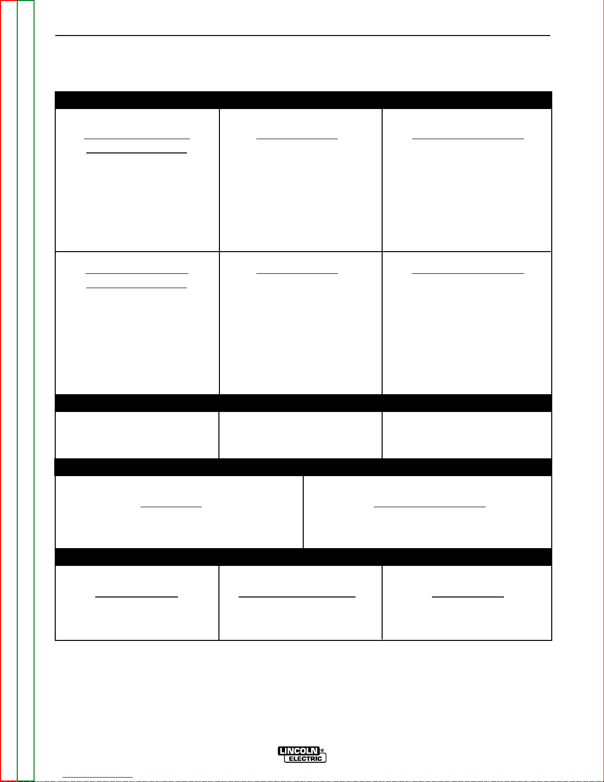
TECHNICAL SPECIFICATIONS - PRO-CUT 55
INPUT RATINGS
Single Phase Input Input Currents Rated Output Amps
Voltage and Hertz
208/1/60 60 55
230/1/60 55 55
460/1/60 30 55
208/1/60 44 40
230/1/60 40 40
460/1/60 23 40
Three Phase Input Input Currents Rated Output Amps
Voltage and Hertz
208/3/60 31 55
230/3/60 28 55
460/3/60 17 55
208/3/60 23 40
230/3/60 21 40
460/3/60 15 40
IDLE CURRENT AND WATTS
230/1/60 0.42 Amps 98 Watts
RATED OUTPUT
Duty Cycle Rated Output Amps
50% 55
100% 40
OUTPUT
Current Range Open Circuit Voltage Pilot Current
25 - 55 Amps 335VDC Maximum 18 Amps @ 100%
Duty Cycle
Return to Section TOC Return to Section TOC Return to Section TOC Return to Section TOC
Return to Master TOC Return to Master TOC Return to Master TOC Return to Master TOC
INSTALLATION
A-3 A-3
PRO-CUT 55
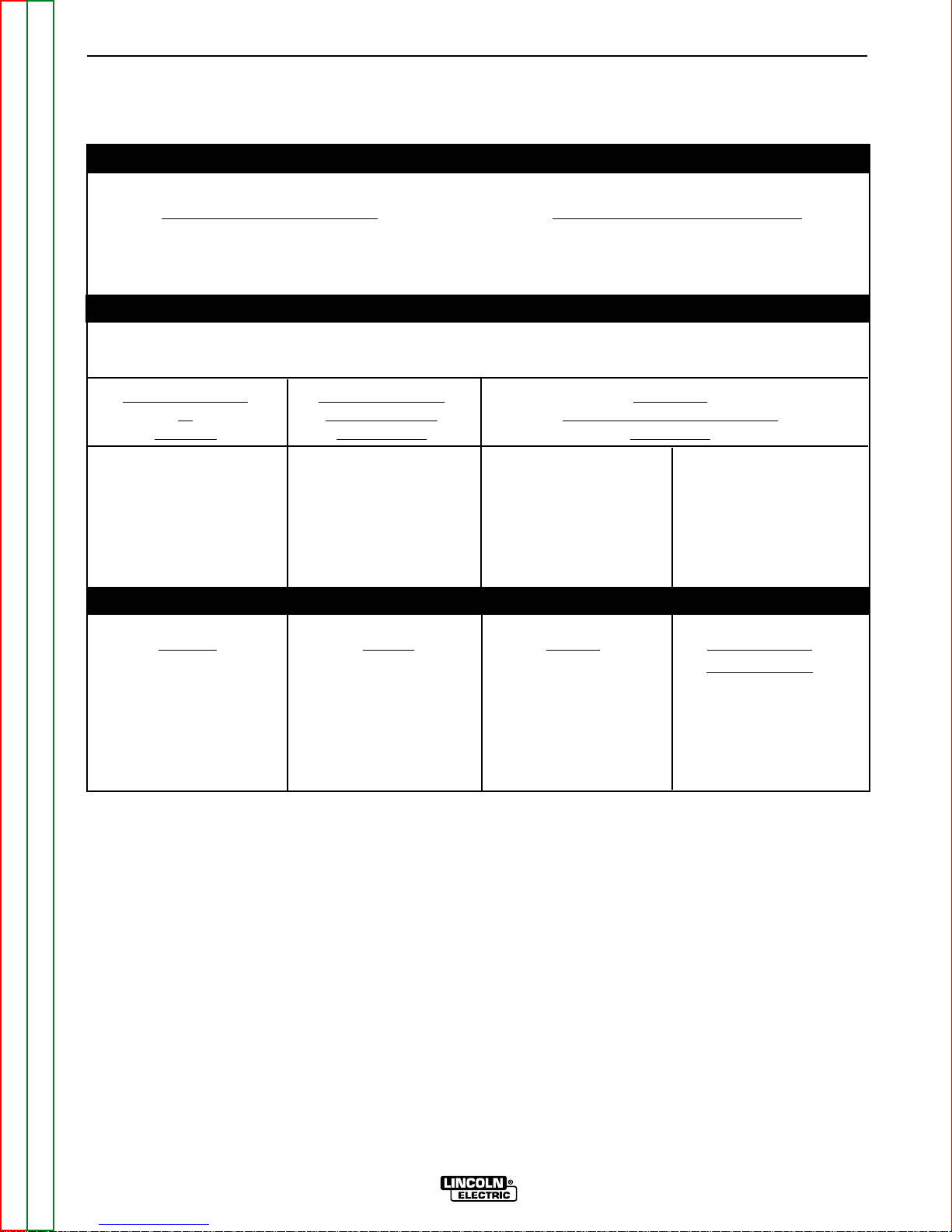
TECHNICAL SPECIFICATIONS (Cont’d) - PRO-CUT 55
GAS REQUIREMENTS
Required Gas Flow Rate Required Gas Inlet Pressure
70 PSI @ 360 SCHF 80 to 150 PSI
(4.8 Bar. @ 10160 LHR) (5.4 Bar. to 10.2 Bar.)
(6 CFM)
RECOMMENDED INPUT WIRE AND FUSE SIZES
For all plasma cutting applications based on U.S. National Electrical Code
Ambient Temperature 30°C or Less
AC Input V
oltage Fuse (Super Lag) Type 75°C
at Circuit Breaker Copper Wire in Conduit AWG
60 Hertz (Delay Type) (IEC) Sizes
2 Input Supply Wires 1 Ground Wire
230VAC Single Phase 70 Amps #8 (8.4mm2) #10 (5.3mm2)
460VAC Single Phase 40 Amps #8 (8.4mm2) #10 (.3mm2)
230VAC Three Phase 40 Amps #10 (5.3mm
2
) #10 (5.3mm2)
460VAC Three Phase 20 Amps #10 (5.3mm2) #10 (5.3mm2)
PHYSICAL DIMENSIONS
Height
Width Depth W
eight with
Torch Cable
12.6 Inches 11.0 Inches 26.0 Inches 70 lbs. (32 kg.)
320 mm 280 mm 660 mm (25 ft. cable)
85 lbs. (39 kg.)
(50 ft. cable)

Read this entire installation section before you
start installation.
SAFETY PRECAUTIONS
ELECTRIC SHOCK can kill.
• Turn the input power OFF at the
disconnect switch or fuse box
and discharge input capacitors
before working inside the equipment.
• Do not touch electrically hot parts or electrodes with
your skin or wet clothing.
• Always connect the 55 grounding terminal (located
on the side of the Case Back Assembly) to a good
electrical earth ground.
• Always wear dry, insulating gloves.
• Turn the 55 Power Switch OFF when connecting
power cord to input power.
Only qualified personnel should install, use, or service this equipment.
SELECT SUITABLE LOCATION
Place the Pro-Cut 55 where clean cool air can freely
circulate in through the rear louvers and out through
the front/bottom opening. Dirt, dust or any foreign
material that can be drawn into the machine should be
kept at a minimum. Failure to observe these precautions can result in excessive operating temperatures
and nuisance shutdown of the machine.
A source of clean, dry air or nitrogen must be supplied
to the Pro-Cut 55. Oil in the air is a severe problem and
must be avoided. The supply pressure must be
between 80 and 150 psi. The flow rate is approximately 6.0 cfm (170 l/min.). Failure to observe these precautions could result in excessive operating temperatures or damage to the torch.
STACKING
The Pro-Cut 55 cannot be stacked.
LIFTING AND MOVING
FALLING EQUIPMENT can cause
injury.
• Do not use the pull handle on the
optional undercarriage, if installed,
to lift the machine. This handle is
not designed to support the full
weight of the machine. Using it to
lift the machine could cause personal injury or damage to the
machine.
• Either the front or rear handles or both may be used
to lift or move the machine.
TILTING
The Pro-Cut 55 must be placed on a stable, level surface so it will not topple over.
HIGH FREQUENCY INTERFERENCE
PROTECTION
The Pro-Cut 55 employs a touch start mechanism for
arc initiation. This eliminates high frequency emissions
from the machine as compared with spark gap and
solid state type high frequency generators. Keep in
mind, though, that these machines may be used in an
environment where other high frequency generating
machines are operating. By taking the following steps,
you can minimize high frequency interference.
• Make sure the power supply chassis is connected to
a good earth ground. The work terminal ground does
NOT ground the machine frame.
• Keep the work ground clamp isolated from other work
clamps that have high frequency.
• If the ground clamp cannot be isolated, then keep the
clamp as far as possible from other work clamp connections.
• When the machine is enclosed in a metal building,
several good earth driven electrical grounds around
the periphery of the building are recommended.
Failure to observe these recommended installation
procedures may cause improper function of the ProCut or possibly even damage the control system or
power supply components.
INSTALLATION
A-4 A-4
PRO-CUT 55
Return to Section TOC Return to Section TOC Return to Section TOC Return to Section TOC
Return to Master TOC Return to Master TOC Return to Master TOC Return to Master TOC
WARNING
WARNING
INPUT CONNECTIONS
ELECTRIC SHOCK can kill.
• Have a qualified electrician install and
service this equipment.
• Turn the input power off at the fuse box
before working on this equipment.
• Do not touch electrically hot parts.
Before installing the machine, check that input supply
voltage, phase, and frequency are the same as the
machine’s voltage, phase, and frequency as specified
on the machine’s rating plate. See Figure A.1.
The Pro-Cut 55 should be connected only by a qualified electrician. Installation should be made in accordance with the U.S. National Electrical Code, all local
codes, and the information detailed below.
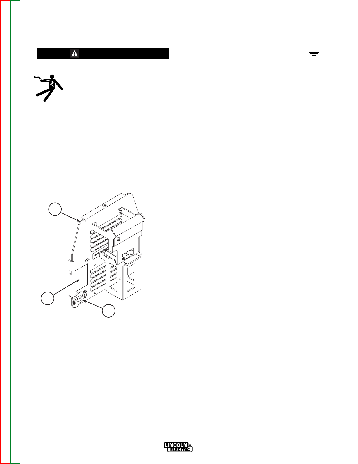
GROUND CONNECTION
The frame of the Pro-Cut 55 must be properly grounded. A ground terminal marked with the symbol is
mounted on the case bottom directly behind the input
power switch for this purpose. The ground lead of the
input power cord that is attached to the machine must
be connected to this ground terminal. See the
National Electric Code for details on proper grounding
methods. Install in accordance with all local and
national electrical codes.
INPUT POWER CORD CONNECTOR
INSTALLATION
The Pro-Cut 55 is supplied with one 11 foot (3.35m) #8
AWG 3 lead input power cord already connected to
the machine. A cord connector provides a strain relief
for the input power cord as it passes through the left
rear access hole. The cord connector is designed for
a cord diameter of .40 - 1.03 in (10.2 - 26.2mm) if it
becomes necessary to install a different input cord.
See Figure A.1.
For three phase connection: Replace the input power
cord with a #10 AWG 4 lead cable.
Connect the leads of the cable to a fused power panel.
Make sure the green lead is connected to the panel
and the panel is connected to a good earth ground.
Install in accordance with all local and national electric
codes.
INPUT WIRE AND FUSE SIZE
Fuse the input circuit with the super lag fuses or delay
type circuit breakers recommended on the Technical
Specifications page. Choose an input and grounding
wire size according to local or national codes; also see
the Technical Specifications page. Using fuses or
circuit breakers smaller than recommended may result
in “nuisance” shut-offs from inrush currents, even if
you are not cutting at high currents.
INSTALLATION
A-5 A-5
PRO-CUT 55
Return to Section TOC Return to Section TOC Return to Section TOC Return to Section TOC
Return to Master TOC Return to Master TOC Return to Master TOC Return to Master TOC
FIGURE A.1 – RATING PLATE LOCATION
1
2
3
WARNING
1. CASE BACK
2. RATING PLATE
3. POWER CORD CONNECTOR WITH STRAIN RELIEF
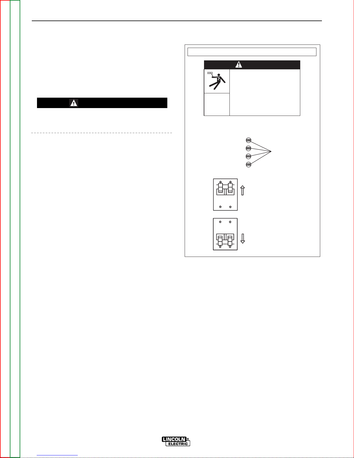
RECONNECT PROCEDURE
When received directly from the factory, the machines
are internally connected for 230 VAC. Reconnection
will be necessary if a higher input voltage is used. To
reconnect the Pro-Cut to 460 VAC or to connect back
to 230 VAC, follow the directions as outlined below.
Follow this procedure ONLY while the Pro-Cut is dis-
connected from the input power.
Failure to follow these instructions can cause immediate failure of components in the welder.
1. Open the access door on the back of the machine.
Connection instructions are also included on the
inside of the door.
2. For 230: Position the large switch to 200-230. See
Figure A.2.
For 460: Position the large switch to 380-460. See
Figure A-2.
3. Move the “A” lead to the appropriate terminal.
FIGURE A.2 – RECONNECTION DIAGRAM
INSTALLATION
A-6 A-6
PRO-CUT 55
Return to Section TOC Return to Section TOC Return to Section TOC Return to Section TOC
Return to Master TOC Return to Master TOC Return to Master TOC Return to Master TOC
CAUTION
VOLTAGE = 380 - 460V
VOLTAGE = 200 - 230V
RECONNECT PROCEDURE
ELECTRIC
SHOCK
CAN KILL
• Disconnect input power before
inspecting or servicing machine.
• Do not operate with wraparound
removed.
• Do not touch electrically live parts.
• Only qualified persons should install,
use, or service this equipment.
WARNING
1. BE SURE POWER SWITCH IS OFF.
2. CONNECT LEAD 'A' TO DESIRED INPUT VOLTAGE RANGE.
440 - 460V
380 - 415V
220 - 230V
200 - 208V
3. POSITION SWITCH TO DESIRED INPUT VOLTAGE RANGE.
'A'
Return to Section TOC Return to Section TOC Return to Section TOC Return to Section TOC
Return to Master TOC Return to Master TOC Return to Master TOC Return to Master TOC
INSTALLATION
A-7 A-7
PRO-CUT 55
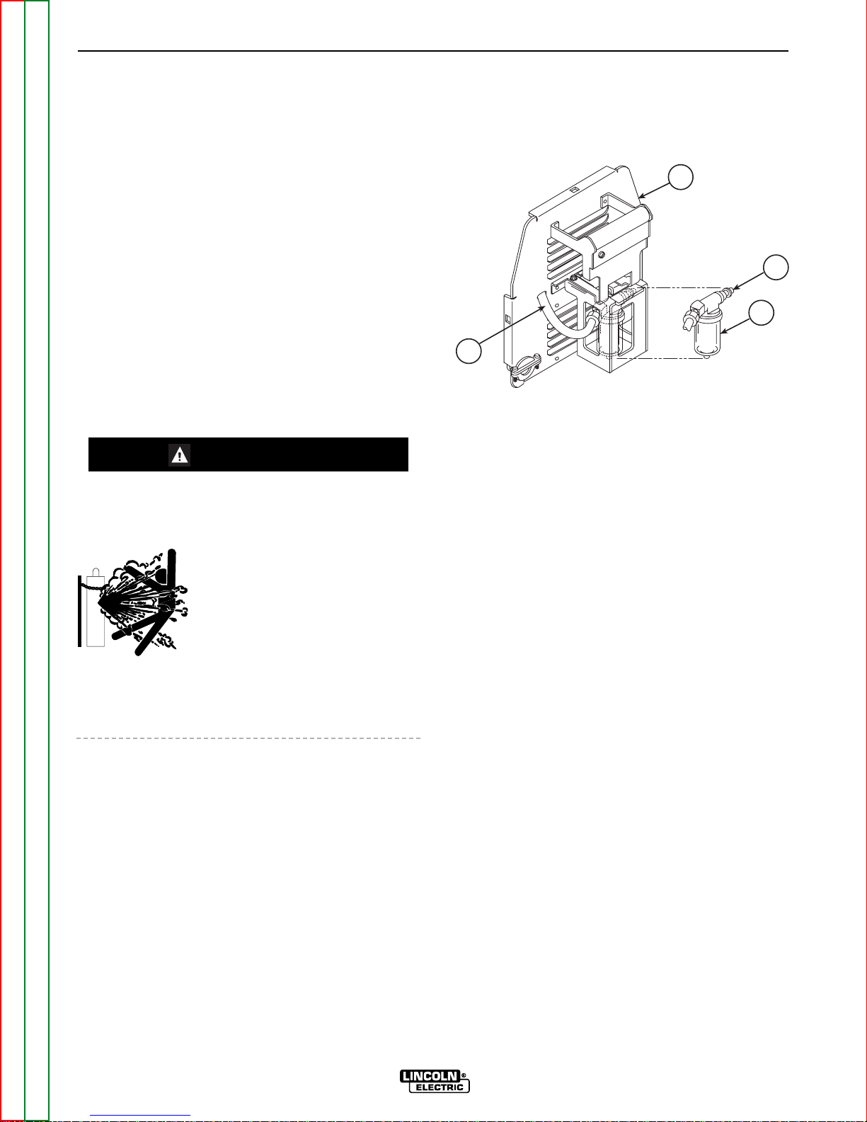
GAS INPUT CONNECTIONS
Supply the Pro-Cut 55 with clean compressed air or
nitrogen.
• Supply pressure must be between 80 psi and 150
psi.
• Flow rate should be approximately 6.0 cfm (170
I/min.).
NOTE: Oil in the air supply to the Pro-Cut 55 can
cause severe problems. Use only a clean air
supply.
• Connect the gas supply to the Pro-Cut 55’s
pneumatic nipple at the air filter. See Figure A.3.
• Compressed gas should be supplied to the fitting
connection mounted on the filter at the rear of the
machine. If necessary, this fitting can be removed
allowing plumbing access through the 1/4 in.
(6.4mm) NPT input port on the filter body.
CYLINDER could explode if damaged.
• Keep cylinder upright and chained to a fixed support.
• Keep cylinder away from areas
where it could be damaged.
• Never lift machine with cylinder
attached.
• Never allow the cutting torch to
touch the cylinder.
• Keep cylinder away from live electrical parts.
• Maximum inlet pressure 150 psi.
NOTE: When using nitrogen gas from a cylinder, the
cylinder must have a pressure regulator.
• Maximum psi from nitrogen gas cylinder to Pro-Cut
55 regulator should never exceed 150 psi.
• Install a hose between the nitrogen gas cylinder regulator and the Pro-Cut 55 gas inlet.
FIGURE A.3 - COMPRESSED GAS CONNECTION
1. CASE BACK
2. PNEUMATIC NIPPLE
3. AIR FILTER
4. FLEX TUBE (TO REGULATOR INSIDE MACHINE)
WARNING
1
2
3
4
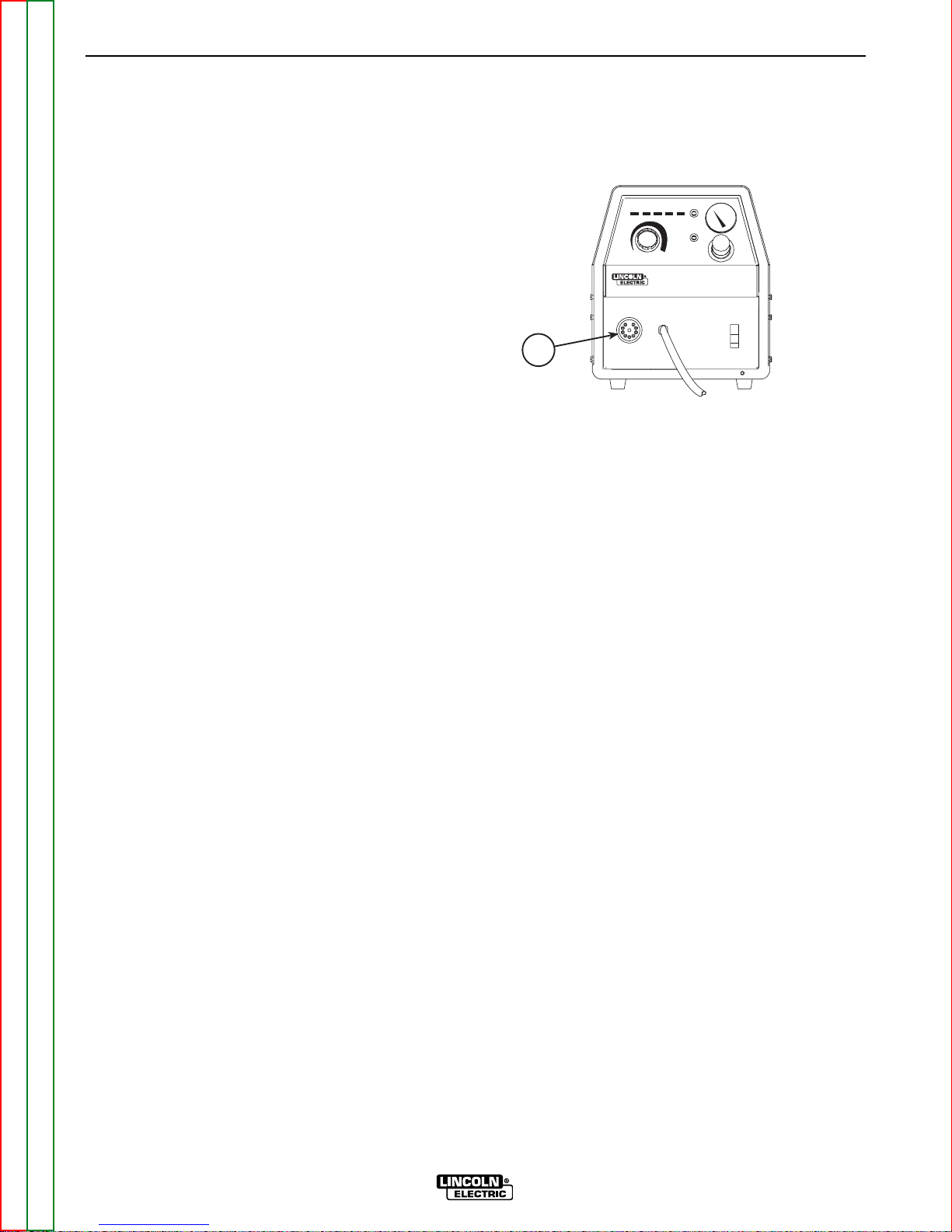
OUTPUT CONNECTIONS
TORCH CONNECTION
The Pro-Cut 55 is supplied from the factory with a PCT
80 cutting torch. Additional cutting torches can be
ordered from the K1571 series. Hand-held and mechanized torches come with 25 or 50 foot cables.
All torches are connected to the Pro-Cut with a quick
connect at the case front for easy change over. See
Figure A-4.
For more information on the torch and its components,
refer to the PCT 80 Operators Manual (IM588).
FIGURE A.4 - TORCH CONNECTION
AT CASE FRONT
1. TORCH CONNECTION
INSTALLATION
A-8 A-8
PRO-CUT 55
Return to Section TOC Return to Section TOC Return to Section TOC Return to Section TOC
Return to Master TOC Return to Master TOC Return to Master TOC Return to Master TOC
1
XXXX XXXX XXXX XXXX
PRO-CUT 55
OFF

Return to Master TOC Return to Master TOC Return to Master TOC Return to Master TOC
Section B-1 Section B-1
PRO-CUT 55
TABLE OF CONTENTS
- OPERATION SECTION -
Operation...............................................................................................................................Section B
Safety Instructions ......................................................................................................................B-2
General Description ....................................................................................................................B-3
Recommended Process and Equipment....................................................................................B-3
Operational Features and Controls ............................................................................................B-3
Design Features and Advantages...............................................................................................B-3
Cutting Capability .......................................................................................................................B-4
Consumable Life.........................................................................................................................B-4
Limitations...................................................................................................................................B-4
Controls and Settings.................................................................................................................B-5
Pilot Arc Considerations .............................................................................................................B-5
Cutting Operation .......................................................................................................................B-5
User Responsibility .....................................................................................................................B-7
Preheat Temperature for Plasma Cutting ...................................................................................B-7
Procedure Recommendations....................................................................................................B-7
General .................................................................................................................................B-7
Thin Gauge Sheet Metal ......................................................................................................B-7
Thick Sections of Metal........................................................................................................B-8
Suggestions for Extra Utility From the Pro-Cut System......................................................B-8

Return to Section TOC Return to Section TOC Return to Section TOC Return to Section TOC
Return to Master TOC Return to Master TOC Return to Master TOC Return to Master TOC
B-2
B-2
PRO-CUT 55
OPERATING INSTRUCTIONS
Read and understand this entire section of operating
instructions before operating the machine.
SAFETY INSTRUCTIONS
ELECTRIC SHOCK can kill.
• Do not touch electrically live parts or
electrodes with your skin or wet clothing.
• Insulate yourself from the work and ground.
• Always wear dry, insulating gloves.
FUMES AND GASES can be
dangerous.
• Keep your head out of fumes.
• Use ventilation or exhaust to remove fumes from
breathing zone.
CUTTING SPARKS can cause
fire or explosion.
• Keep flammable material away.
• Do not cut containers that have held combustibles.
ARC RAYS can burn.
• Wear eye, ear, and body protection.
PLASMA ARC can injure.
• Keep your body away from nozzle and
plasma arc.
• Operate the pilot arc with caution. The
pilot arc is capable of burning the operator, others, or even piercing safety
clothing.
Observe additional Safety Guidelines detailed in
the beginning of this manual.
WARNING
OPERATION

GENERAL DESCRIPTION
The Pro-Cut 55 is an inverter based constant current,
continuous control plasma cutting power source. It
provides superior and reliable starting characteristics,
cutting visibility and arc stability. When cutting
expanded metal, the Pro-Cut 55 out-performs the
competition due to its quick, clean response to arc
transfers. The power supply design provides high
transfer-to-cut distances, which makes pierce cutting
more reliable with less nozzle wear. The control system
has a safety mechanism to insure that the nozzle and
electrode are in place before cutting or gouging. This
is extremely important due to the high voltages
involved.
The Pro-Cut 55 comes standard with an air regulator,
coarse air filter, and pressure gauge. The machine also
comes with an 11 foot (3.35m) input power cord. There
are four different torch and cable systems to choose
from: hand-held torch with 25 foot (7.62m) or 50 foot
(15.24m) cable, machine and robotic torch both with
25 foot (7.62m) and 50 foot (15.24m) cable.
Consumables are included with each Pro-Cut purchase so that cutting can begin right out of the box.
Consumables can also be ordered as individual packages. An undercarriage kit can be ordered separately.
The Pro-Cut 55 initiates the plasma arc with a simple,
yet reliable, touch-start mechanism. This system eliminates many of the failure problems associated with hifrequency start systems. The Pro-Cut 55 is capable of
cutting with nitrogen or air.
The Pro-Cut 55 is controlled by a microprocessorbased control board. The machine performs rudimentary self troubleshooting when powered up, which aids
in field servicing.
RECOMMENDED PROCESSES AND
EQUIPMENT
The Pro-Cut 55 is capable of all cutting and gouging
applications within its output capacity of 25 to 55
amps. These applications include thin gage sheet
metal and expanded metal.
OPERATIONAL FEATURES AND
CONTROLS
The Pro-Cut 55 comes with an ON/OFF POWER
SWITCH, OUTPUT CURRENT CONTROL, PURGE
BUTTON, STATUS INDICATORS and a SAFETY
RESET BUTTON. See Figure B.2 and related discussion.
DESIGN FEATURES AND
ADVANTAGES
The microprocessor controlled Pro-Cut 55 design
makes plasma cutting and gouging tasks uncomplicated. This list of design features and advantages will
help you understand the machine's total capabilities
so that you can get maximum use from your machine.
• Light weight and portable design for industrial use.
• Continuous control, 25 - 55 amps.
• Reliable touch start mechanism for plasma arc initiation.
• Unique microprocessor controlled starting
sequence for safe and consistent starting.
• Rapid arc transfer for fast cutting of expanded
metal.
• High transfer distance for ease of use.
• Input overvoltage protection.
• 3.0 second pilot arc.
• Purge momentary push button.
• Air regulator and pressure gauge located on the
front of machine for convenience.
• ”Parts-in-Place” mechanism to detect proper installation of consumables and torch.
• Automatic detection of faulty output control.
• In-line coarse air filter.
• Preflow/Postflow timing. Preflow is eliminated if arc
is re-initiated in Postflow.
• Thermostatic Protection.
• Solid state overcurrent protection.
• Works with pure nitrogen for cutting nonferrous
materials.
• Reconnectable for 230 VAC or 460 VAC inputs.
• Quick disconnect torch.
• Display indicators for machine status.
• Unique electrode and Vortech™ nozzle design for
optimum cooling and long life.
• Swirl texture inside Vortech™ nozzle for better starting reliability and higher quality cuts.
• Unique drag cup design for durability and elimination of double arcing.
OPERATION
B-3 B-3
PRO-CUT 55
Return to Section TOC Return to Section TOC Return to Section TOC Return to Section TOC
Return to Master TOC Return to Master TOC Return to Master TOC Return to Master TOC
CUTTING CAPABILITY
The Pro-Cut 55 is rated at 55 amps, at 50% duty cycle
on a 10 minute basis or 40 amps, at 100% duty cycle.
If the duty cycle is exceeded, a thermal protector will
shut off the output of the machine until it cools to the
normal operating temperature.
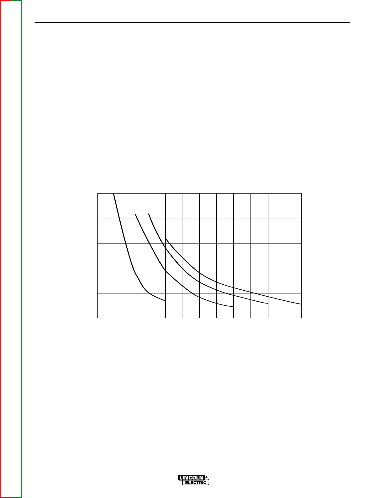
Figure B.1 shows the cut capacity of the Pro-Cut 55
when cutting mild steel. The graph plots cut thickness
vs. torch travel speed with a torch standoff of 0.15 in.
(3.8mm).
Example: 0.25 material
Amps
Speed (IPM)
35 38
45 57
55 62
FIGURE B.1 – LINCOLN’S PRO-CUT 55 MILD STEEL CUT CAPACITY CHART
CONSUMABLE LIFE
The expected life for the Pro-Cut 55's electrode under
normal operating conditions is approximately 320
starts/cuts. An erosion of .060 in. (1.5mm) is typical for
end of electrode life. However, the electrode may last
longer. A green and erratic arc will indicate definite
electrode failure, and the electrode should be
replaced immediately.
It is recommended that consumables be replaced in
complete sets. (Example: Electrode and Nozzle). This
will maximize the performance of the Pro-Cut 55 system.
LIMITATIONS
Do not exceed output current and duty cycle rating of
machine. Do not use the Pro-Cut 55 for pipe thawing.
OPERATION
B-4 B-4
PRO-CUT 55
Return to Section TOC Return to Section TOC Return to Section TOC Return to Section TOC
Return to Master TOC Return to Master TOC Return to Master TOC Return to Master TOC
Recommended Torch Travel Speed (IPM)
80% of Maximum Speed
100
80
60
40
20
0
0.000 0.125 0.250
0.375 0.500 0.625 0.750
Material Thickness
25 A
35 A
45 A
55 A
Return to Section TOC Return to Section TOC Return to Section TOC Return to Section TOC
Return to Master TOC Return to Master TOC Return to Master TOC Return to Master TOC
OPERATION
B-5 B-5
PRO-CUT 55
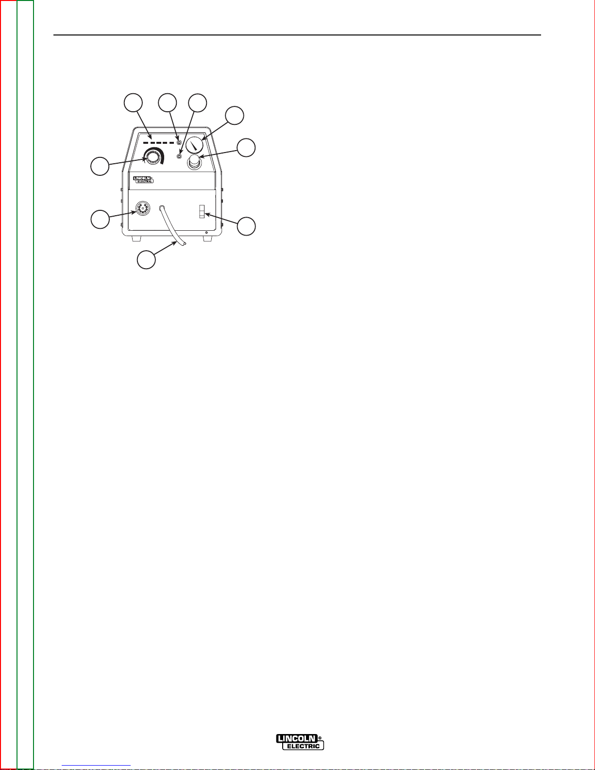
CONTROLS AND SETTINGS
FIGURE B.2 - CASE FRONT CONTROLS
1. OUTPUT CURRENT CONTROL KNOB
2. TORCH CONNECTOR
3. WORK CABLE
4. INPUT POWER SWITCH
5. GAS REGULATOR KNOB
6. GAS REGULATOR GAUGE
7. GAS PURGE BUTTON
8. RESET BUTTON
9. STATUS (DISPLAY) BOARD INDICATORS
1. OUTPUT CURRENT CONTROL KNOB - Adjusts
the amount of cutting current applied. Affects cutting speed, dross formation, cut width, heat zone
and travel speed.
2. TORCH CONNECTOR - Quick-connect type coupling for the PCT 80 cutting torch.
3. WORK CABLE - Provides clamp and cable connection to workpiece.
4.
ON/OFF POWER SWITCH - Turns machine on or off.
5. GAS REGULATOR KNOB - Adjusts compressed
gas pressure delivered to the torch. Length of
torch hose is an adjustment factor. Optimum setting is 70-75 psi. The gas purge button must be
pressed in to set pressure.
6. GAS REGULATOR GAUGE - Provides gas pressure
reading as set by the gas regulator knob.
7. GAS PURGE BUTTON - Used to check or set gas
pressure. Push in and hold to check pressure, then
continue to hold to set the pressure. Shuts off gas
when released.
8. RESET BUTTON - Used to reset the machine following a safety circuit trip.
9. STATUS (DISPLAY) BOARD INDICATORS - Four
lights indicating Power, Gas Low, Thermal and
Safety.
PILOT ARC CONSIDERATIONS
The Pro-Cut has a smooth, continuous pilot arc. The
pilot arc is only a means of transferring the arc to the
workpiece for cutting. Repeated pilot arc starts, in
rapid succession, is not recommended as these starts
will generally reduce consumable life. Occasionally,
the pilot arc may sputter or start intermittently. This is
aggravated when the consumables are worn or the air
pressure is too high. Always keep in mind that the
pilot arc is designed to transfer the arc to the workpiece and not for numerous starts without cutting.
When the pilot arc is started, a slight impulse will be
felt in the torch handle. This occurrence is normal and
is the mechanism which starts the plasma arc. This
impulse can also be used to help troubleshoot a "no
start" condition.
CUTTING OPERATION
When preparing to cut or gouge, position the machine
as close to the work as possible. Make sure you have
all materials needed to complete the job and have
taken all safety precautions. It is important to follow
these operating steps each time you use the machine.
• Turn the machine's ON/OFF POWER SWITCH to
the OFF position.
• Connect the air supply to the machine.
• Turn the main power and the machine power switch
on.
- The fan should start.
- The pre-charge circuit will operate for 3 seconds,
then the green "Power" status indicator should
turn on.
- If the "SAFETY" status indicator is lit, push the
"Reset" button. If there is no problem, the status
indicator will go off. If there is a problem, refer to
"STATUS INDICATOR" in this section.
• Be sure that the work lead is clamped to the workpiece before cutting.
• Set the output current control knob for maximum
current for high cutting speed and less dross formation per Figure B.1. Reduce the current, if desired,
to reduce the kerf (cut) width, heat affected zone or
travel speed as required.
• Push-in and hold the Purge button to check or set
the gas pressure. Pull the pressure regulator cap out
and turn it to set the pressure.
- Adjust the gas regulator for 70 PSI for 25 foot
(7.62m) torches or 75 PSI for 50 foot (15.24m)
torches.
- Release the Purge button.
OFF
XXXX XXXX XXXX XXXX
PRO-CUT 55
1
2
3
4
5
6
7
89
- The gas will immediately turn off. The pressure
gauge may show an increase in pressure after the
air turns off, but this is normal. Do NOT reset the
pressure while the air is NOT flowing.
• When ready to cut, place the torch near the work,
make certain all safety precautions have been taken
and pull the trigger.
- The air will flow for a preflow time of 2 seconds
and the pilot arc will start. (This is true unless the
machine is in postflow, then the preflow time is
skipped and the pilot arc will start immediately.)
- The pilot arc will run for 3 seconds and shut off
unless the arc is brought in contact with the work
and the arc is transferred. Avoid excessive pilot
arc time by transferring the arc to the workpiece
quickly to improve parts life.
- When the arc is brought within 1/4 in. (6.4mm)
from the workpiece the arc will transfer, the current will ramp up to the setting on the control
panel, and the cut can last indefinitely (or until the
duty cycle of the Pro-Cut is exceeded). Do not
touch the nozzle to the work when cutting.
Damage to the consumables may result.
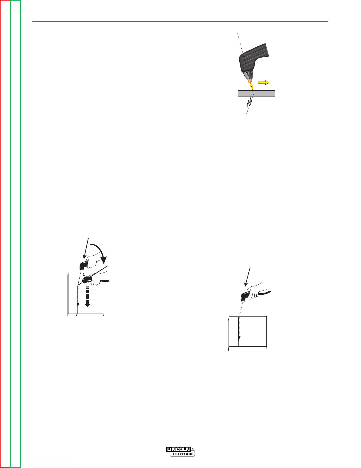
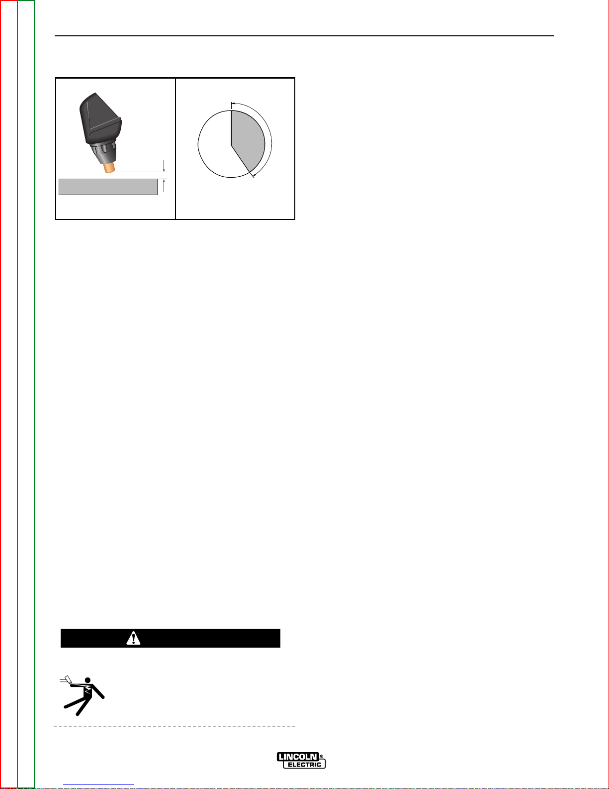
• Pierce the workpiece by slowly lowering the torch
onto the metal at a 30° angle away from the operator. This will blow the dross away from the torch tip.
Slowly rotate the torch to vertical position as the arc
becomes deeper.
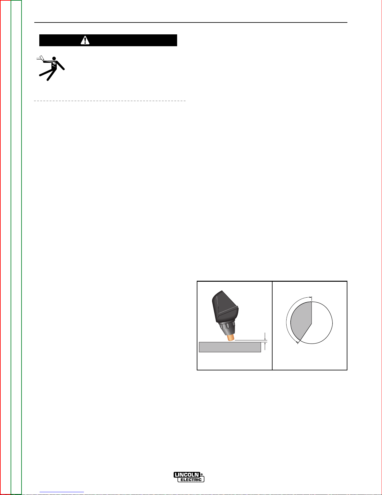
• Hold the nozzle standoff 1/8 in. (3.2mm) to 3/16 in.
(4.7mm) above the workpiece during cutting. Do not
let the torch nozzle touch the work or carry a long
arc.
• Keep moving while cutting. Cut at a steady speed
without pausing. Maintain the cutting speed so that
the arc lag is 10° to 20° behind the travel direction.
•
Use a 5° - 15° leading angle in the direction of the cut.
• Use the drag cup to maintain constant standoff for
better cut quality and to protect the nozzle from
spatter.
• Use the drag cup with a metal template to prevent
nozzle double arcing.
• Finish the cut to be made and release the trigger.
• When the trigger is released, the arc will stop.
- The gas will continue to flow for 10 seconds of
postflow. If the trigger is activated within this time
period, the pilot arc will immediately restart.
• If the dross is difficult to remove, reduce the cutting
speed. High speed dross is more difficult to remove
than low speed dross.
• The right side of the cut is more square than the left
as viewed along the direction of travel.
• Clean spatter and scale from the nozzle and drag
cup frequently.
• For gouging, tilt the torch about 45° from the work-
piece and hold the nozzle 1/8 in. (3.2mm) to 3/16”
(4.7mm) above the workpiece.
SAFETY STATUS INDICATOR
• If the "SAFETY" status indicators light at any time,
check the following:
- Check the assembly of the torch consumables. If
they are not properly in place, the machine will not
start. Make sure that the shield cup is hand
tight. Do not use pliers or over tighten.
OPERATION
B-6 B-6
PRO-CUT 55
Return to Section TOC Return to Section TOC Return to Section TOC Return to Section TOC
Return to Master TOC Return to Master TOC Return to Master TOC Return to Master TOC
3030
00
VERVERTICAL ANGLETICAL ANGLE
FOR CUTTINGFOR CUTTING
CUT
90
0
TORCH AT 300ANGLE
TO PIERCE
ROTATE TO
90
0
ANGLE TO CUT
ANGLE
MAINTAINED
THROUGHOUT
GOUGE
TORCH HELD AT
45
0
ANGLE
THROUGHOUT GOUGE
ANGLE
OF APPROACH
Direction of Travel
5° - 15°
10° - 20°
Arc Lag
Leading Angle
ELECTRIC SHOCK can kill.
• Turn off machine at the disconnect
switch on the front of the machine
before tightening, cleaning or replacing consumables.
- Check the conditions of the inside of the nozzle. If
debris has collected, rub the electrode on the
inside bottom of the nozzle to remove any oxide
layer that may have built up. Refer to
“Suggestions for Extra Utility from the Pro-Cut
System.”
-
Check the condition of the electrode. If the end has
a crater-like appearance, replace it along with the
nozzle. The maximum wear depth of the electrode
is approximately .062 in. (1.6mm). A green and
erratic arc will indicate definite electrode failure.
The electrode should be replaced immediately.
• Replace the nozzle when the orifice exit is eroded
away or oval shaped.
• After the problem is found, or if there is nothing
apparently wrong, reset the machine by pressing
the "Reset" button. (It is possible for electrical noise
to trip the safety circuit on rare occasions. This
should not be a regular occurrence.)
• If the machine does not reset or continues to trip,
consult the Troubleshooting Section.
• Use the proper cutting or gouging procedures
referred to in “Procedure Recommendations”
below.
USER RESPONSIBILITY
Because design, fabrication, erection and cutting variables affect results, the serviceability of a product or
structure is the responsibility of the user. Variation
such as plate chemistry, plate surface condition (oil,
scale), plate thickness, preheat, quench, gas type, gas
flow rate and equipment may produce results different
from those expected. Some adjustments to procedures may be necessary to compensate for unique
individual conditions. Test all procedures duplicating
actual field conditions.
PREHEAT TEMPERATURE FOR
PLASMA CUTTING
Preheat temperature control is not necessary in most
applications when plasma arc cutting or gouging.
Preheat temperature control may be necessary on
high carbon alloy steels and heat treated aluminum for
crack resistance and hardness control. Job conditions, prevailing codes, alloy level, and other considerations may also require preheat temperature control.
The recommended minimum preheat temperature for
plate thickness up to 1/2 in. (12.7mm) is 70°F (21.1°C).
Higher temperatures may be used as required by the
job conditions and/or prevailing codes. If cracking or
excessive hardness occurs on the cut face, higher preheat temperature may be required.
PROCEDURE RECOMMENDATIONS
When properly used, plasma arc cutting or gouging is
a very economical process. Improper use will result in
a very high operating cost.
GENERAL - IN ALL CASES
• Follow safety precautions as printed throughout this
manual and on the machine.
THIN GAUGE SHEET METAL
Output set below mid-range.
• The nozzle may be dragged on the metal surface,
touching it lightly to the surface after piercing a hole.
Current control should be set below the mid-range.
• Do not allow cable or body to contact hot surface.
OPERATION
B-7 B-7
PRO-CUT 55
Return to Section TOC Return to Section TOC Return to Section TOC Return to Section TOC
Return to Master TOC Return to Master TOC Return to Master TOC Return to Master TOC
Torch Standoff
DRAG thru 1/16"
Standoff
Output Setting
Min. thru Mid. Range
Machine Output Setting
WARNING
Output Setting
Min. thru Mid-Range
THICK SECTIONS OF METAL
Output set above mid-range.
• The best quality and consumable life will be
obtained by holding the torch off the surface about
3/16 in. (4.7mm). Too long an arc may compromise
cut quality and consumable life. The nozzle should
NOT be dragged on the work.
• Use of the S22151 Drag Cup will maintain the proper standoff. The only time not to use the drag cup
when the output control is set above mid-range is in
special, tight corners. Always hold at least a 1/8 in.
(3.2mm) standoff in those situations.
• If piercing is required, slowly lower the torch at an
angle of about 30° to blow the dross away from the
torch tip and slowly rotate the torch to a vertical
position as the arc becomes deeper. This process
will blow a lot of molten metal and dross. Be careful! Blow the dross away from the torch, the operator and any flammable objects.
• Where possible, start the cut from the edge of the
workpiece.
• Keep moving! A steady speed is necessary. Do not
pause.
• Do not allow the torch cable or body to contact a
hot surface.
SUGGESTIONS FOR EXTRA UTILITY
FROM THE PRO-CUT SYSTEM
ELECTRIC SHOCK can kill.
• Turn off machine at the disconnect
switch on the front of the machine
before tightening, cleaning or replacing consumables.
1. Occasionally an oxide layer may form over the tip
of the electrode, creating an insulating barrier
between the electrode and nozzle. This will result in
the tripping of the Pro-Cut's safety circuit. When
this happens, turn the power off, remove the nozzle and electrode and use the electrode to rub
against the inside bottom surface of the nozzle.
This will help remove any oxide buildup. Replace
the nozzle, turn on the power and continue cutting.
If the Parts-in-Place circuit (safety status indicator
light) continues to trip after cleaning the consumables, replace them with a new set. Do not continue to cut with excessively worn consumables as
this can cause damage to the torch head and will
degrade cut quality.
2. To improve consumable life, here are some suggestions that may be useful:
a. Never drag the nozzle on the work surface if
the output control knob is above the midrange setting.
b. Make sure the air supply to the Pro-Cut is
clean and free of oil. Use several extra in-line
filters if necessary.
c. Use the lowest output setting possible to
make a good quality cut at the desired cut
speed.
d. Minimize dross buildup on the nozzle tip by
starting the cut from the edge of the plate
when possible.
e. Pierce cutting should be done only when nec-
essary. If piercing, angle the torch about 30°
from the plane perpendicular to the workpiece, transfer the arc, then bring the torch
perpendicular to the work and begin parallel
movement.
f. Reduce the number of pilot arc starts without
transferring to the work.
g. Reduce the pilot arc time before transferring to
the work.
h. Set air pressure to recommended setting. A
higher or lower pressure will cause turbulence
in the plasma arc, eroding the orifice of the
nozzle tip.
i. Use only Lincoln consumable parts. These
parts are patented. Using any other replacement consumables may cause damage to the
torch or reduce cut quality.
OPERATION
B-8 B-8
PRO-CUT 55
Return to Section TOC Return to Section TOC Return to Section TOC Return to Section TOC
Return to Master TOC Return to Master TOC Return to Master TOC Return to Master TOC
WARNING
Torch Standoff
1/8" thru 3/16"
Standoff
Output Setting
Mid. thru Max. Range
Machine Output Setting

TABLE OF CONTENTS
- ACCESSORIES -
Accessories...........................................................................................................................Section C
Options/Accessories...................................................................................................................C-2
Section C-1 Section C-1
PRO-CUT 55
Return to Master TOC Return to Master TOC Return to Master TOC Return to Master TOC
GENERAL OPTIONS /
ACCESSORIES
The following options/accessories are available for
your Pro-Cut 55 from your local Lincoln Distributor.
K1600-1 Undercarriage - A valet style undercarriage
with pull-out handle for machine only. Provides torch
and work cable storage.
S22147-043 - Vortech™ nozzle with an .043” (1.2 mm)
Orifice
S22147-068 - Vortech™ nozzle with an .068” (1.7 mm)
Orifice
S22149 - Electrode - replacement electrodes for cutting.
S22150 - Shield Cup - This shields the torch tip and
provides more visibility to the workpiece than the drag
cup. The shield cup does not prevent the torch tip
from touching the workpiece.
S22151 - Drag Cup - The drag cup protects the torch
by preventing the torch from touching the workpiece.
K1571 Series - PCT 80 Torches come in 25’ and 50’
lengths in either hand held or mechanized versions.
ALWAYS USE GENUINE LINCOLN ELECTRIC
ELECTRODES AND VORTECH™ NOZZLES
• Only Genuine Lincoln Electric consumables yield
the best cutting performance for the Pro-Cut 55.
• The patent pending VORTECH™ nozzle provides
an extra “kick” of swirl as the arc exits the nozzle,
which improves cutting performance. No other nozzle has this capability or can match its performance.
ACCESSORIES
C-2 C-2
PRO-CUT 55
Return to Section TOC Return to Section TOC Return to Section TOC Return to Section TOC
Return to Master TOC Return to Master TOC Return to Master TOC Return to Master TOC

Return to Master TOC Return to Master TOC Return to Master TOC Return to Master TOC
Section D-1 Section D-1
PRO-CUT 55
TABLE OF CONTENTS
-MAINTENANCE-
Maintenance .........................................................................................................................Section D
Safety Precautions......................................................................................................................D-2
Input Filter Capacitor Discharge Procedure...............................................................................D-2
Routine Maintenance..................................................................................................................D-3
Periodic Maintenance .................................................................................................................D-3
ELECTRIC SHOCK can kill.
• Have an electrician install and service
this equipment.
• Turn the input power off at the fuse box
before working on equipment.
• Do not touch electrically hot parts.
• Prior to performing preventative maintenance, perform the following capacitor discharge procedure to
avoid electric shock.
INPUT FILTER CAPACITOR
DISCHARGE PROCEDURE
1. Turn off input power or disconnect input power
lines.
2. Remove the 5/16 in. hex head screws from the side
and top of the machine and remove wrap-around
machine cover.
3. Be careful not to make contact with the capacitor
terminals that are located on the top and bottom of
the Power Board on the right side of the machine.
4. Obtain a high resistance and high wattage resistor
(25-1000 ohms and 25 watts minimum). This resistor is not supplied with machine. NEVER USE A
SHORTING STRAP FOR THIS PROCEDURE.
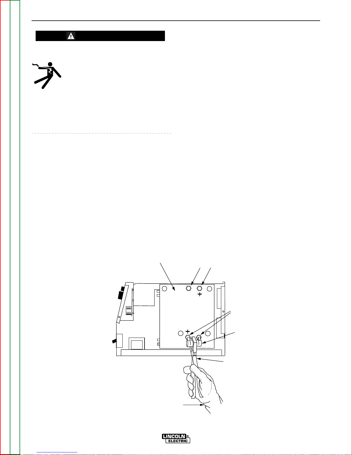
5. Locate the two capacitor terminals (large hex head
cap screws) on the top and bottom of the Power
Board shown in Figure D.1.
6. Use electrically insulated gloves and insulated pliers. Hold the body of the resistor and connect
resistor leads across the two capacitor terminals.
Hold the resistor in place for 10 seconds. DO NOT
TOUCH CAPACITOR TERMINALS WITH YOUR
BARE HANDS.
7. Repeat the discharge procedure for the other
capacitor.
8. Check voltage across the terminals of all capacitors with a DC voltmeter. Polarity of capacitor terminals is marked on the Power Board above terminals. Voltage should be zero. If any voltage
remains, repeat this capacitor discharge procedure.
MAINTENANCE
D-2 D-2
PRO-CUT 55
Return to Section TOC Return to Section TOC Return to Section TOC Return to Section TOC
Return to Master TOC Return to Master TOC Return to Master TOC Return to Master TOC
WARNING
UPPER
CAP ACIT OR TERMINALS
LOWER
CAPACITOR
TERMINALS
INSULATED
GLOVES
INSULATED
PLIERS
POWER
RESISTOR
POWER
BOARD
RIGHT SIDE OF MACHINE
FIGURE D.1 — LOCATION OF INPUT FILTER CAPACITOR TERMINALS

Return to Section TOC Return to Section TOC Return to Section TOC Return to Section TOC
Return to Master TOC Return to Master TOC Return to Master TOC Return to Master TOC
MAINTENANCE
D-3 D-3
PRO-CUT 55
ROUTINE MAINTENANCE
1. Keep the cutting or gouging area and the area
around the machine clean and free of combustible
materials. No debris should be allowed to collect
which could obstruct air flow to the machine.
2. Every 6 months or so, the machine should be
cleaned with a low pressure airstream. Keeping the
machine clean will result in cooler operation and
higher reliability. Be sure to clean these areas (Refer
to Figure D.2):
- Power, Output and Control printed circuit boards
and heat sinks
- Power Switch
- Main Transformer
- Input Rectifier
3. Examine the sheet metal case for dents or breakage. Repair the case as required. Keep the case in
good condition to insure that high voltage parts are
protected and correct spacings are maintained. All
external sheet metal screws must be in place to
insure case strength and electrical ground continuity.
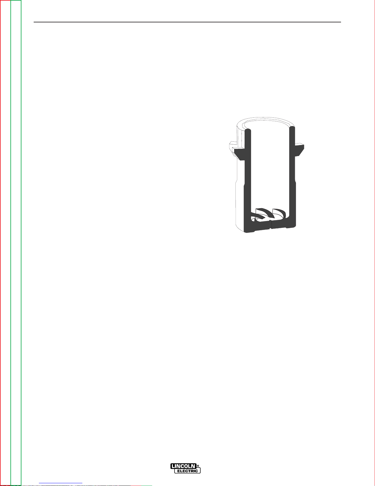
4. Check the air regulator filter to be sure it does not
become clogged. The air filter on the machine is
self draining and will not have to be emptied.
5. Check the filter element every several months to
see if it is clogged (weekly in very dirty environments). Replace if necessary by first removing the
two screws that attach the filter cage to the back
panel assembly, then slide the cage away from the
back of the machine and remove. Next, twist the
clear filter bowl until it comes off (be careful not to
lose the o-ring seated at the top of the bowl
threads). Unscrew the filter element and replace
with new element. Assemble parts in reverse order
as described above.
6. Inspect the cable periodically for any slits or puncture marks in the cable jacket. Replace if necessary. Check to make sure that nothing is crushing
the cable and blocking the flow of air through the
air tube inside. Also, check for kinks in the cable
periodically and relieve any so as not to restrict the
flow of air to the torch.
PERIODIC MAINTENANCE
ELECTRIC SHOCK can kill.
• Turn off machine at the disconnect
switch on the front of the machine
before tightening, cleaning or replacing
consumables.
Change consumables as required.
1. Thermal Protection
Two thermostats protect the machine from excessive
operating temperatures. Excessive temperatures may
be caused by a lack of cooling air or by operating the
machine beyond the duty cycle and output rating. If
excessive operating temperatures should occur, the
yellow thermal LED will light and the thermostat will
prevent output voltage or current.
Thermostats are self-resetting once the machine cools
sufficiently. If the thermostat shutdown was caused by
excessive output or duty cycle and the fan is operating normally, the Power Switch may be left on and the
reset should occur within a 15 minute period. If the fan
is not turning or the air intake louvers were obstructed,
then the power must be switched off and the fan problem or air obstruction must be corrected.
2. Filter Capacitor Conditioning (Pro-Cut 55, 400-460
VAC only)
A protection circuit is included to monitor the voltage
across filter capacitors C1 and C2. In the event that
the capacitor voltage is too high, the protection circuit
will prevent output. The protection circuit may prevent
output providing all these circumstances are met:
a. Machine is connected for 400-460 VAC input.
b. Machine did not have power applied for many
months.
c. Machine will not produce output when power is
first switched on.
If these circumstances apply, the proper action is to
switch the machine on and let it idle for up to 30 minutes. This is required to condition the filter capacitors
after an extended storage time. The protection circuit
will automatically reset once the capacitor conditioning and resultant voltage levels are acceptable. It may
be necessary to turn the power switch off and back on
again after this period.
WARNING
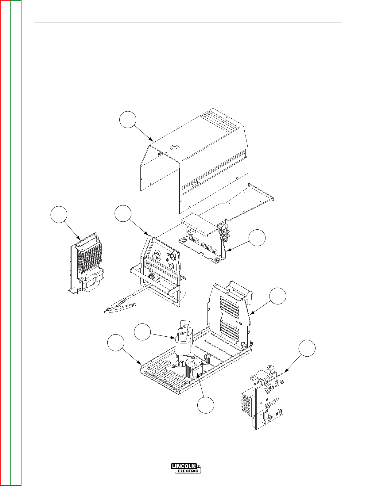
1. Case Front
2. Case Back
3. Primary Power Board
4. Output Power Board Assembly
5. Control Board
6. Case Wraparound
7. Machine Base
8. Auxiliary Transformer
9. Main Transformer
Maintenance
D-4 D-4
PRO-CUT 55
Return to Section TOC Return to Section TOC Return to Section TOC Return to Section TOC
Return to Master TOC Return to Master TOC Return to Master TOC Return to Master TOC
FIGURE D.2 – MAJOR COMPONENT LOCATIONS
6
3
1
5
2
4
7
8
9
Return to Master TOC Return to Master TOC Return to Master TOC Return to Master TOC
Section E-1 Section E-1
PRO-CUT 55
Theory of Operation .............................................................................................................Section E
General Description ....................................................................................................................E-2
Input Line Voltage, Contactor and Main Transformer.................................................................E-2
Precharge and Protection ...........................................................................................................E-3
Main Transformer ........................................................................................................................E-4
Output Board and Torch .............................................................................................................E-5
Control and Display Boards........................................................................................................E-6
Protection Circuits ......................................................................................................................E-7
Overload Protection..............................................................................................................E-7
Thermal Protection ...............................................................................................................E-7
Insulated Gate Bipolar Transistor (IGBT) Operation ...................................................................E-8
Pulse Width Modulation (PWM) ..................................................................................................E-9
TABLE OF CONTENTS
-THEORY OF OPERATION SECTION-
INPUT
LINE
SWITCH
INPUT
RECTIFIER
FAN
MOTORS
"A"
L
E
A
D
AUXILIARY
TRANSFORMER
OUTPUT
CONTROL
AIR
PRESSURE
SWITCH
P
R
O
T
E
C
T
O
N
I
SIGNAL
CR 1
DRIVE
SIGNAL
RELAY
IGBT
GATE
SIGNALS
R
E
A
D
Y
A
I
R
L
O
W
T
H
E
R
M
A
L
S
A
F
E
Y
T
TRIGGER & SAFETY
ELECTRODE & TRANSFER
CURRENT FEEDBACK
PILOT ENABLE
ELECTRODE SOLENOID ENABLE
AIR SOLENOID ENABLE
AIR
SOLENOID
TRIGGER & SAFETY
E
L
E
C
T
R
O
D
E
S
O
L
E
N
O
I
D
TORCH
CONNECTOR
ELECTRODE
NOZZLE
WORK
R
E
C
O
N
N
E
C
T
S
W
T
C
H
I
POWER BOARD
CR 1
RELAY
IGBT
IGBT
IGBT
IGBT
CAPACITOR
CAPACITOR
CURRENT
TRANSFORMER
CONTROL BOARD
DISPLAY BOARD
18/36VAC
12VAC
24VAC
MAIN
TRANSFORMER
OUTPUT BOARD
CHOKE
PILOT
TRANSISTOR
THERMOSTATS
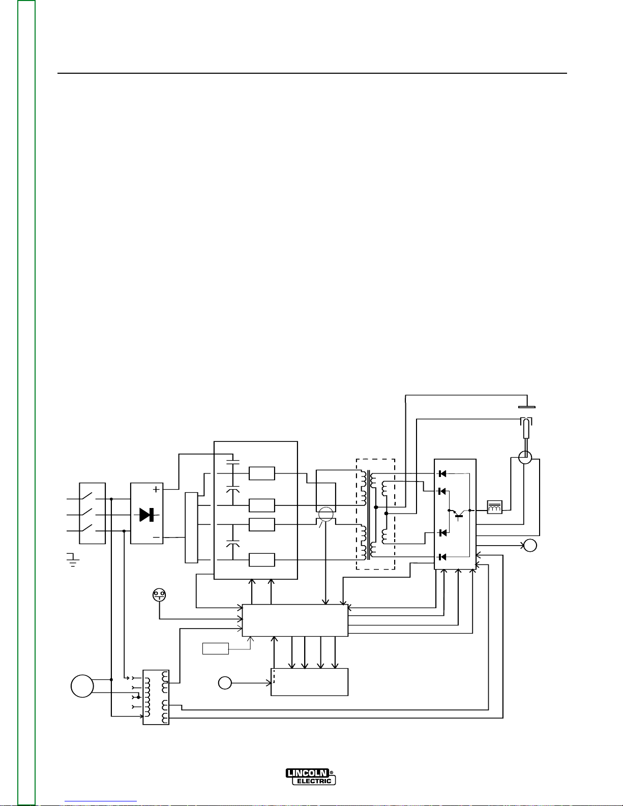
FIGURE E.1 – PRO-CUT 55 BLOCK LOGIC DIAGRAM
GENERAL DESCRIPTION
The Pro-Cut 55 is a constant current, continuous control plasma cutting power source. The inverter based
power supply design is controlled by a microprocessor
control board. The control system has a safety mechanism to insure that the nozzle and electrode are in
place before cutting or gouging. The Pro-Cut 55 initiates the plasma arc with a simple, yet reliable, touch
start mechanism. This system eliminates many of the
problems associated with hi-frequency type start systems.
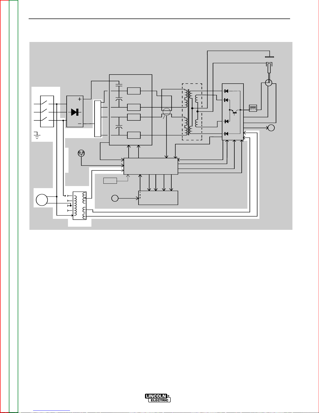
INPUT LINE VOLTAGE,
CONTACTOR AND MAIN
TRANSFORMER
The single-phase or three-phase input power of 200230 or 400 to 460 volts AC is connected to the
machine, via an input line cord, to a switch located on
the front panel.
A reconnect panel and voltage range switch allow the
user to configure the machine for either a low or high
input voltage and also connect the auxiliary transformer for the appropriate input voltage.
The auxiliary transformer develops the appropriate AC
voltages to operate the cooling fans, the control board
and the plasma output board.
THEORY OF OPERATION
E-2 E-2
PRO-CUT 55
Return to Section TOC Return to Section TOC Return to Section TOC Return to Section TOC
Return to Master TOC Return to Master TOC Return to Master TOC Return to Master TOC
FIGURE E.2 – INPUT LINE VOLTAGE
NOTE: Unshaded areas of Block Logic Diagram are the subject of discussion.
INPUT
LINE
SWITCH
INPUT
RECTIFIER
FAN
MOTORS
"A"
L
E
A
D
AUXILIARY
TRANSFORMER
OUTPUT
CONTROL
AIR
PRESSURE
SWITCH
P
R
O
T
E
C
T
O
N
I
SIGNAL
CR 1
DRIVE
SIGNAL
RELAY
IGBT
GATE
SIGNALS
R
E
A
D
Y
A
I
R
L
O
W
T
H
E
R
M
A
L
S
A
F
E
Y
T
TRIGGER & SAFETY
ELECTRODE & TRANSFER
CURRENT FEEDBACK
PILOT ENABLE
ELECTRODE SOLENOID ENABLE
AIR SOLENOID ENABLE
AIR
SOLENOID
TRIGGER & SAFETY
E
L
E
C
T
R
O
D
E
S
O
L
E
N
O
I
D
TORCH
CONNECTOR
ELECTRODE
NOZZLE
WORK
R
E
C
O
N
N
E
C
T
S
W
T
C
H
I
POWER BOARD
CR 1
RELAY
IGBT
IGBT
IGBT
IGBT
CAPACITOR
CAPACITOR
CURRENT
TRANSFORMER
CONTROL BOARD
DISPLAY BOARD
18/36VAC
12VAC
24VAC
MAIN
TRANSFORMER
OUTPUT BOARD
CHOKE
PILOT
TRANSISTOR
THERMOSTATS
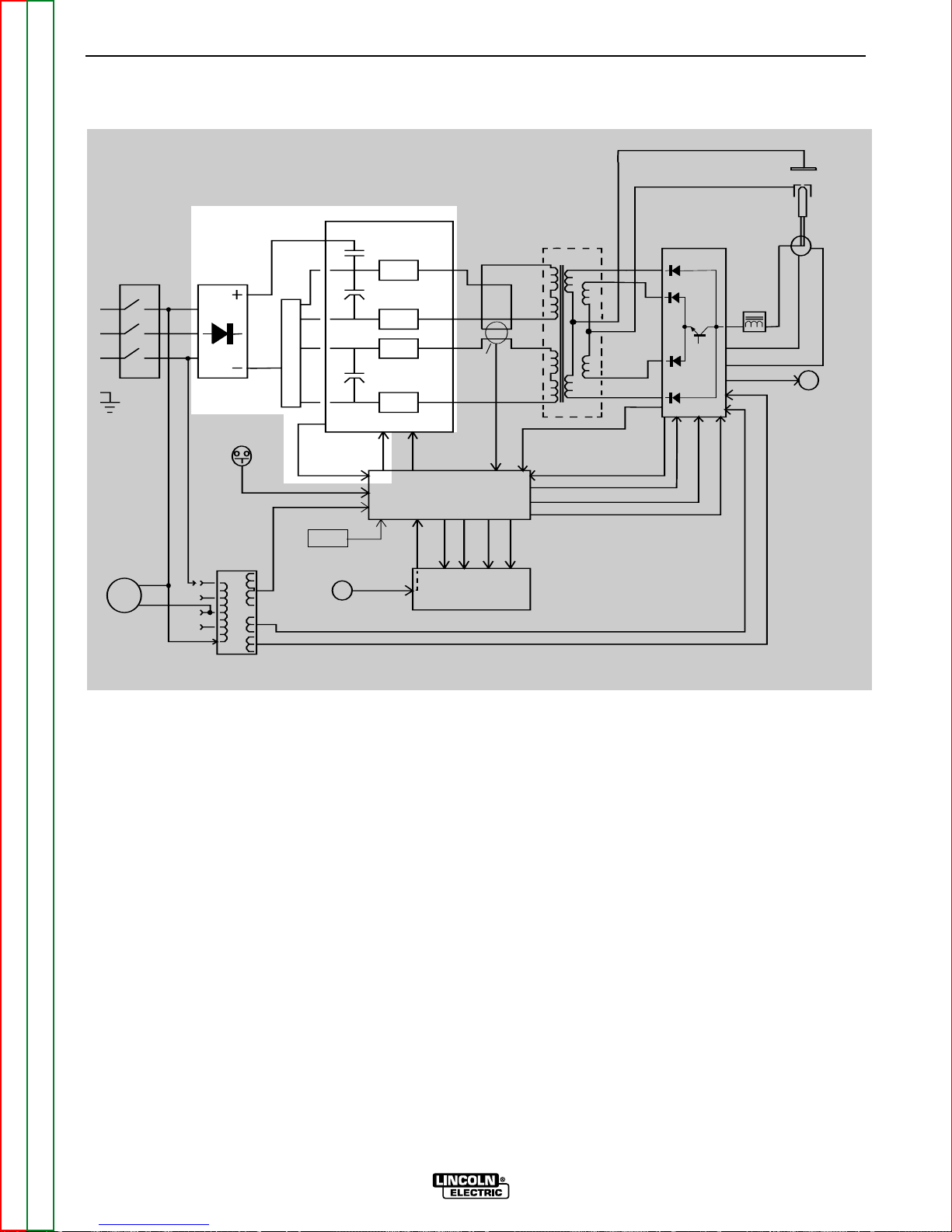
PRECHARGE AND PROTECTION
The input voltage is rectified by the input rectifier. The
resultant DC voltage is applied, through the reconnect
switch, to the power board. The power board contains
precharging circuitry for the safe charging of the input
filter capacitors. Once the capacitors are precharged
and balanced the control board activates the CR1
input relay. This connects full input power to the filter
capacitors. When the filter capacitors are fully
charged they act as power supplies for the IGBT
switching circuit. The Insulated Gate Bipolar Transistors supply the main transformer primary winding
with DC current flow. See IGBT Operation discussion
and diagrams in this section.
The power board also monitors the filter capacitors for
voltage balance and under or overvoltage. If either
should occur, the appropriate signal is sent to the control board to deactivate the CR1 input relay. The
machine output will also be disabled.
THEORY OF OPERATION
E-3 E-3
PRO-CUT 55
Return to Section TOC Return to Section TOC Return to Section TOC Return to Section TOC
Return to Master TOC Return to Master TOC Return to Master TOC Return to Master TOC
NOTE: Unshaded areas of Block Logic Diagram are the subject of discussion.
FIGURE E.3 – PRECHARGE AND PROTECTION
INPUT
LINE
SWITCH
INPUT
RECTIFIER
FAN
MOTORS
"A"
L
E
A
D
AUXILIARY
TRANSFORMER
OUTPUT
CONTROL
AIR
PRESSURE
SWITCH
P
R
O
T
E
C
T
O
N
I
SIGNAL
CR 1
DRIVE
SIGNAL
RELAY
IGBT
GATE
SIGNALS
R
E
A
D
Y
A
I
R
L
O
W
T
H
E
R
M
A
L
S
A
F
E
Y
T
TRIGGER & SAFETY
ELECTRODE & TRANSFER
CURRENT FEEDBACK
PILOT ENABLE
ELECTRODE SOLENOID ENABLE
AIR SOLENOID ENABLE
AIR
SOLENOID
TRIGGER & SAFETY
E
L
E
C
T
R
O
D
E
S
O
L
E
N
O
I
D
TORCH
CONNECTOR
ELECTRODE
NOZZLE
WORK
R
E
C
O
N
N
E
C
T
S
W
T
C
H
I
POWER BOARD
CR 1
RELAY
IGBT
IGBT
IGBT
IGBT
CAPACITOR
CAPACITOR
CURRENT
TRANSFORMER
CONTROL BOARD
DISPLAY BOARD
18/36VAC
12VAC
24VAC
MAIN
TRANSFORMER
OUTPUT BOARD
CHOKE
PILOT
TRANSISTOR
THERMOSTATS
 Loading...