

Lincoln Electric Power MIG 360MP Operator's Manual

Operator’s Manual
Register your machine:
www.lincolnelectric.com/register
Authorized Service and Distributor Locator:
www.lincolnelectric.com/locator
For use with machines having Code Numbers:
12910
Save for future reference
Date Purchased
Code: (ex: 10859)
Serial: (ex: U1060512345)
Power MIG®360MP
Need Help? Call 1.888.935.3877
to talk to a Service Representative
Hours of Operation:
8:00 AM to 6:00 PM (ET) Mon. thru Fri.
After hours?
Use “Ask the Experts” at lincolnelectric.com
A Lincoln Service Representative will contact you
no later than the following business day.
For Service outside the USA:
Email: globalservice@lincolnelectric.com
IM10547 | Issue D ate Oct-19
© Lincoln Global, Inc. All Rights Reserved.
THANK YOU FOR SELECTING
A QUALITY PRODUCT BY
LINCOLN ELEC TRIC.
PLEASE EXAMINE CARTON AND EQUIPMENT FOR
DAMAGE IMMEDIATELY
When this equipment is shipped, title passes to the purchaser
upon receipt by the carrier. Consequently, claims for material
damaged in shipment must be made by the purchaser against the
transportation company at the time the shipment is received.
SAFETY DEPENDS ON YOU
Lincoln arc welding and cutting equipment is designed and built
with safety in mind. However, your overall safety can be increased
by proper installation ... and thoughtful operation on your part.
DO NOT INSTALL, OPERATE OR REPAIR THIS EQUIPMENT
WITHOUT READING THIS MANUAL AND THE SAFETY
PRECAUTIONS CONTAINED THROUGHOUT. And, most importantly,
think before you act and be careful.
This statement appears where the information must be followed
exactly to avoid serious personal injury or loss of life.
This statement appears where the information must be followed
to avoid minor personal injury or damage to this equipment.
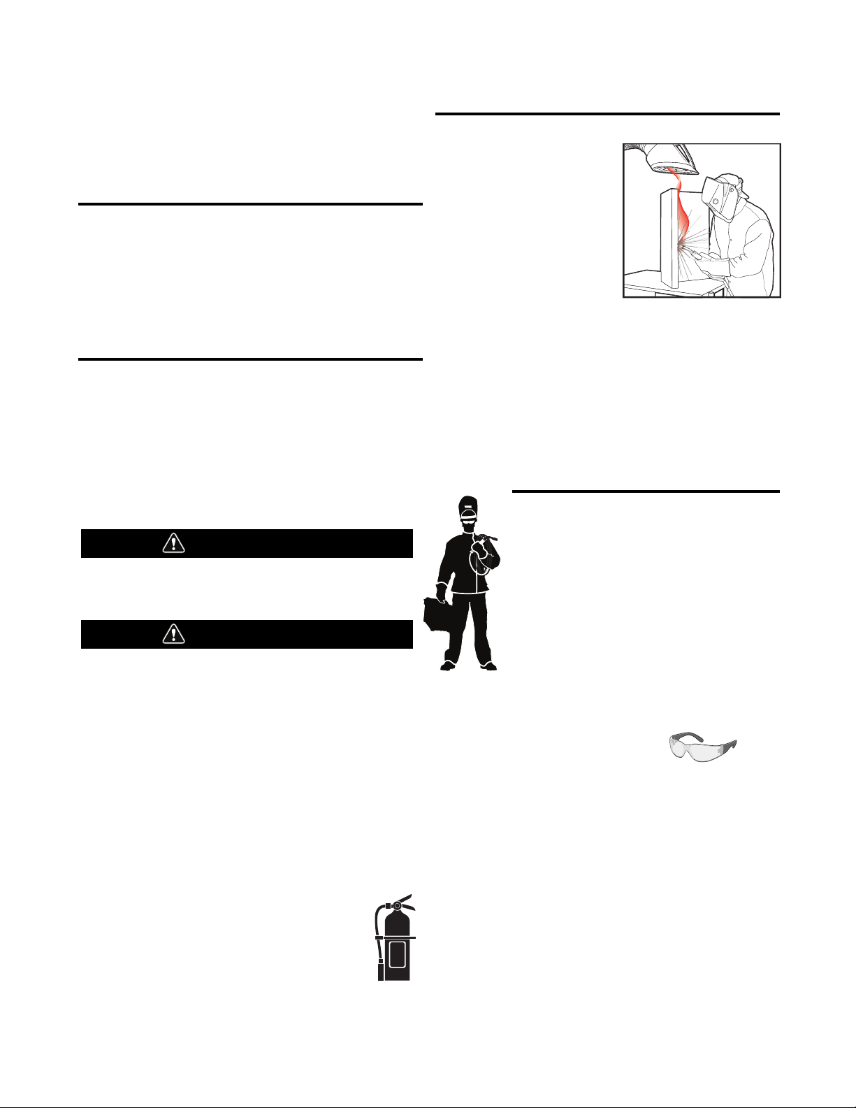
KEEP YOUR HEAD OUT OF THE FUMES.
DON’T get too close to the arc.
Use corrective lenses if necessary
to stay a reasonable distance
away from the arc.
READ and obey the Safety Data
Sheet (SDS) and the warning label
that appears on all containers of
welding materials.
USE ENOUGH VENTILATION or
exhaust at the arc, or both, to
keep the fumes and gases from
your breathing zone and the general area.
IN A LARGE ROOM OR OUTDOORS, natural ventilation may be
adequate if you keep your head out of the fumes (See below).
USE NATURAL DRAFTS or fans to keep the fumes away
from your face.
If you de velop unusual symptoms, see your supervisor.
Perhaps the welding atmosphere and ventilation system
should be checked.
WEAR CORRECT EYE, EAR &
BODY PROTECTION
PROTECT your eyes and face with welding helmet
properly fitted and with proper grade of filter plate
(See ANSI Z49.1).
PROTECT your body from welding spatter and arc
flash with protective clothing including woolen
clothing, flame-proof apron and gloves, leather
leggings, and high boots.
PROTECT others from splatter, flash, and glare
with protective screens or barriers.
IN SOME AREAS, protection from noise may be appropriate.
BE SURE protective equipment is in good condition.
Also, wear safety glasses in work area
AT ALL TIMES.
SPECIAL SITUATIONS
DO NOT WELD OR CUT containers or materials which previously
had been in contact with hazardous substances unless they are
properly cleaned. This is extremely dangerous.
DO NOT WELD OR CUT painted or plated parts unless special
precautions with ventilation have been taken. They can release
highly toxic fumes or gases.
Additional precautionary measures
PROTECT compressed gas cylinders from excessive heat,
mechanical shocks, and arcs; fasten cylinders so they cannot fall.
BE SURE cylinders are never grounded or part of an
electrical circuit.
REMOVE all potential fire hazards from welding area.
ALWAYS HAVE FIRE FIGHTING EQUIPMENT READY FOR
IMMEDIATE USE AND KNOW HOW TO USE IT.
WARNING
CAUTION
Safety 01 of 04 - 5/16/2018

SECTION A:
WARNINGS
CALIFORNIA PROPOSITION 65 WARNINGS
WARNING: Breathing diesel engine exhaust
exposes you to chemicals known to the State
of California to cause cancer and birth defects,
or other reproductive harm.
• Always start and operate the engine in a
well-ventilated area.
• If in an exposed area, vent the exhaust to the outside.
• Do not modify or tamper with the exhaust system.
• Do not idle the engine except as necessary.
For more information go to
www.P65 warnings.ca.gov/diesel
WARNING: This product, when used for welding or
cutting, produces fumes or gases which contain
chemicals known to the State of California to cause
birth defects and, in some cases, cancer. (California
Health & Safety Code § 25249.5 et seq.)
WARNING: Cancer and Reproductive Harm
www.P65warnings.ca.gov
ARC WELDING CAN BE HAZARDOUS. PROTECT
YOURSELF AND OTHERS FROM POSSIBLE SERIOUS
INJURY OR DEATH. KEEP CHILDREN AWAY.
PACEMAKER WEARERS SHOULD CONSULT WITH
THEIR DOCTOR BEFORE OPERATING.
Read and understand the following safety highlights. For
additional safety information, it is strongly recommended
that you purchase a copy of “Safety in Welding & Cutting ANSI Standard Z49.1” from the American Welding Society,
P.O. Box 351040, Miami, Florida 33135 or CSA Standard
W117.2-1974. A Free copy of “Arc Welding Safety” booklet
E205 is available from the Lincoln Electric Company,
22801 St. Clair Avenue, Cleveland, Ohio 44117-1199.
BE SURE THAT ALL INSTALLATION, OPERATION,
MAINTENANCE AND REPAIR PROCEDURES ARE
PERFORMED ONLY BY QUALIFIED INDIVIDUALS.
FOR ENGINE POWERED
EQUIPMENT.
1.a. Turn the engine off before troubleshooting
and maintenance work unless the
maintenance work requires it to be running.
1.b. Operate engines in open, well-ventilated areas or vent the engine
exhaust fumes outdoors.
1.c. Do not add the fuel near an open flame welding
arc or when the engine is running. Stop the
engine and allow it to cool before refueling to
prevent spilled fuel from vaporizing on contact
with hot engine parts and igniting. Do not spill fuel when filling
tank. If fuel is spilled, wipe it up and do not start engine until
fumes have been eliminated.
1.d. Keep all equipment safety guards, covers
and devices in position and in good repair.
Keep hands, hair, clothing and tools away
from V-belts, gears, fans and all other
moving parts when starting, operating or
repairing equipment.
1.e. In some cases it may be necessary to remove safety guards to
perform required maintenance. Remove guards only when
necessary and replace them when the maintenance requiring
their removal is complete. Always use the greatest care when
working near moving parts.
1.f. Do not put your hands near the engine fan. Do not attempt to
override the governor or idler by pushing on the throttle control
rods while the engine is running.
1.g. To prevent accidentally starting gasoline engines while turning
the engine or welding generator during maintenance work,
disconnect the spark plug wires, distributor cap or magneto wire
as appropriate.
1.h. To avoid scalding, do not remove the radiator
pressure cap when the engine is
hot.
ELECTRIC AND
MAGNETIC FIELDS MAY
BE DANGEROUS
2.a. Electric current flowing through any conductor
causes localized Electric and Magnetic Fields (EMF).
Welding current creates EMF fields around welding cables
and welding machines
2.b. EMF fields may interfere with some pacemakers, and
welders having a pacemaker should consult their physician
before welding.
2.c. Exposure to EMF fields in welding may have other health effects
which are now not known.
2.d. All welders should use the following procedures in order to
minimize exposure to EMF fields from the welding circuit:
2.d.1. Route the electrode and work cables together - Secure
them with tape when possible.
2.d.2. Never coil the electrode lead around your body.
2.d.3. Do not place your body between the electrode and work
cables. If the electrode cable is on your right side, the
work cable should also be on your right side.
2.d.4. Connect the work cable to the workpiece as close as possible to the area being welded.
2.d.5. Do not work next to welding power source.
SAFETY
Safety 02 of 04 - 5/16/2018
ELECTRIC SHOCK
CAN KILL.
3.a. The electrode and work (or ground) circuits are
electrically “hot” when the welder is on. Do
not touch these “hot” parts with your bare skin or wet clothing.
Wear dry, hole-free gloves to insulate hands.
3.b. Insulate yourself from work and ground using dry insulation.
Make certain the insulation is large enough to cover your full area
of physical contact with work and ground.
In addition to the normal safety precautions, if
welding must be performed under electrically
hazardous conditions (in damp locations or while
wearing wet clothing; on metal structures such as
floors, gratings or scaffolds; when in cramped
positions such as sitting, kneeling or lying, if there
is a high risk of unavoidable or accidental contact
with the workpiece or ground) use the following
equipment:
• Semiautomatic DC Constant Voltage (Wire) Welder.
• DC Manual (Stick) Welder.
• AC Welder with Reduced Voltage Control.
3.c. In semiautomatic or automatic wire welding, the electrode,
electrode reel, welding head, nozzle or semiautomatic welding
gun are also electrically “hot”.
3.d. Always be sure the work cable makes a good electrical
connection with the metal being welded. The connection should
be as close as possible to the area being welded.
3.e. Ground the work or metal to be welded to a good electrical (earth)
ground.
3.f. Maintain the electrode holder, work clamp, welding cable and
welding machine in good, safe operating condition. Replace
damaged insulation.
3.g. Never dip the electrode in water for cooling.
3.h. Never simultaneously touch electrically “hot” parts of electrode
holders connected to two welders because voltage
between the
two can be the total of the open circuit voltage of both
welders.
3.i. When working above floor level, use a safety belt to protect
yourself from a fall should you get a shock.
3.j. Also see It ems 6.c. and 8.
ARC RAYS CAN BURN.
4.a. Use a shield with the proper filter and cover plates to protect your
eyes from sparks and the rays of the arc when welding or
observing open arc welding. Headshield and filter lens should
conform to ANSI Z87. I standards.
4.b. Use suitable clothing made from durable flame-resistant material
to protect your skin and that of your helpers from the arc rays.
4.c. Protect other nearby personnel with suitable, non-flammable
screening and/or warn them not to watch the arc nor expose
themselves to the arc rays or to hot spatter or metal.
FUMES AND GASES
CAN BE DANGEROUS.
5.a. Welding may produce fumes and gases
hazardous to health. Avoid breathing these
fumes and gases. When welding, keep your head out of the fume.
Use enough ventilation and/or exhaust at the arc to keep fumes
and gases away from the breathing zone. When welding
hardfacing (see instructions on container or SDS)
or on lead or cadmium plated steel and other
metals or coatings which produce highly toxic
fumes, keep exposure as low as possible and
within applicable OSHA PEL and ACGIH TLV limits
using local exhaust or mechanical ventilation
unless exposure assessments indicate otherwise.
In confined spaces or in some circumstances,
outdoors, a respirator may also be required.
Additional precautions are also required when
welding
on galvanized steel.
5. b. The operation of welding fume control equipment is affected by
various factors including proper use and positioning of the
equipment, maintenance of the equipment and the specific
welding procedure and application involved. Worker exposure
level should be checked upon installation and periodically
thereafter to be certain it is within applicable OSHA PEL and
ACGIH TLV limits.
5.c. Do not weld in locations near chlorinated hydrocarbon vapors
coming from degreasing, cleaning or spraying operations. The
heat and rays of the arc can react with solvent vapors to form
phosgene, a highly toxic gas, and other irritating products.
5.d. Shielding gases used for arc welding can displace air and
cause
injury or death. Always use enough ventilation, especially in
confined areas, to insure breathing air is safe.
5.e. Read and understand the manufacturer’s instructions for this
equipment and the consumables to be used, including the
Safety Data Sheet (SDS) and follow your employer’s safety
practices. SDS forms are available from your welding
distributor or from the manufacturer.
5.f. Also see item 1.b.
SAFETY
Safety 03 of 04 - 5/16/2018
WELDING AND CUTTING
SPARKS CAN CAUSE
FIRE OR EXPLOSION.
6.a. Remove fire hazards from the welding area. If
this is not possible, cover them to prevent the welding sparks
from starting a fire. Remember that welding sparks and hot
materials from welding can easily go through small cracks and
openings to adjacent areas. Avoid welding near hydraulic lines.
Have a fire extinguisher readily available.
6.b. Where compressed gases are to be used at the job site, special
precautions should be used to prevent hazardous situations.
Refer to “Safety in Welding and Cutting” (ANSI Standard Z49.1)
and the operating information for the equipment being used.
6.c. When not welding, make certain no part of the electrode circuit is
touching the work or ground. Accidental contact can cause
overheating and create a fire hazard.
6.d. Do not heat, cut or weld tanks, drums or containers until the
proper steps have been taken to insure that such procedures
will not cause flammable or toxic vapors from substances inside.
They can cause an explosion even though they have been
“cleaned”. For information, purchase “Recommended Safe
Practices for the Preparation for Welding and Cutting of
Containers and Piping That Have Held Hazardous Substances”,
AWS F4.1 from the American Welding Society
(see address above).
6.e. Vent hollow castings or containers before heating, cutting or
welding. They may explode.
6.f. Sparks and spatter are thrown from the welding arc. Wear oil free
protective garments such as leather gloves, heavy shirt, cuffless
trousers, high shoes and a cap over your hair. Wear ear plugs
when welding out of position or in confined places. Always wear
safety glasses with side shields when in a welding area.
6.g. Connect the work cable to the work as close to the welding area
as practical. Work cables connected to the building framework or
other locations away from the welding area increase the
possibility of the welding current passing through lifting chains,
crane cables or other alternate circuits. This can create fire
hazards or overheat lifting chains or cables until they fail.
6.h. Also see item 1.c.
6.I. Read and follow NFPA 51B “Standard for Fire Prevention During
Welding, Cutting and Other Hot Work”, available from NFPA, 1
Batterymarch Park, PO box 9101, Quincy, MA 022690-9101.
6.j. Do not use a welding power source for pipe thawing.
CYLINDER MAY EXPLODE IF
DAMAGED.
7.a. Use only compressed gas cylinders containing
the correct shielding gas for the process used
and properly operating regulators designed for
the gas and pressure used. All hoses, fittings,
etc. should be suitable for the application and
maintained in good condition.
7.b. Always keep cylinders in an upright position securely chained to
an undercarriage or fixed support.
7.c. Cylinders should be located:
• Away from areas where they may be struck or subjected
to physical damage.
• A safe distance from arc welding or cutting operations
and any other source of heat, sparks, or flame.
7.d. Never allow the electrode, electrode holder or any other
electrically “hot” parts to touch a cylinder.
7.e. Keep your head and face away from the cylinder valve outlet
when opening the cylinder valve.
7.f. Valve protection caps should always be in place and hand tight
except when the cylinder is in use or connected for use.
7.g. Read and follow the instructions on compressed gas cylinders,
associated equipment, and CGA publication P-l, “Precautions for
Safe Handling of Compressed Gases in Cylinders,” available from
the Compressed Gas Association, 14501 George Carter Way
Chantilly, VA 20151.
FOR ELECTRICALLY
POWERED EQUIPMENT.
8.a. Turn off input power using the disconnect
switch at the fuse box before working on
the equipment.
8.b. Install equipment in accordance with the U.S. National Electrical
Code, all local codes and the manufacturer’s recommendations.
8.c. Ground the equipment in accordance with the U.S. National
Electrical Code and the manufacturer’s recommendations.
Refer to
http://www.lincolnelectric.com/safety
for additional safety information.
SAFETY
Safety 04 of 04 - 5/16/2018

2
TABLE OF CONTENTS
INSTALLATION .............................................................................................................................................SECTION A
TECHNICAL SPECIFICATIONS – POWER MIG
®
360MP................................................................................................A.1
INSTALLATION ...........................................................................................................................................................A.2
UNCRATING THE POWER MIG
®
360MP ......................................................................................................................A.2
LOCATION .............................................................................................................................................................A.2
TILTING .............................................................................................................................................................A.2
OUTPUT POLARITY CONNECTIONS .............................................................................................................................A.3
INPUT POWER, GROUNDING AND CONNECTION DIAGRAM ..........................................................................................A.3
GUN AND CABLE INSTALLATION.................................................................................................................................A.4
SHIELDING GAS..........................................................................................................................................................A.5
AUXILIARY POWER RECEPTACLES ..............................................................................................................................A.5
OPERATION ................................................................................................................................................SECTION B
PRODUCT DESCRIPTION ............................................................................................................................................B-1
RECOMMENDED PROCESSES AND EQUIPMENT .........................................................................................................B-1
WELDING CAPABILITY................................................................................................................................................B-1
LIMITATIONS ............................................................................................................................................................B-1
SETTING THE POWER MIG
®
360 MACHINE TO WELD.................................................................................................B-1
GRAPHIC SYMBOLS USED IN THIS MANUAL...............................................................................................................B-1
CASE FRONT CONTROLS ...........................................................................................................................................B-2
CASE BACK CONTROLS .............................................................................................................................................B-2
INTERNAL CONTROLS................................................................................................................................................B-3
READY.SET.WELD™..................................................................................................................................................B-4
WELD PROCESSES ....................................................................................................................................................B-5
WELD SETTINGS........................................................................................................................................................B-6
ARC CONTROL...........................................................................................................................................................B-7
SPECIAL WELDING PROCESSES ................................................................................................................................B-8
WIRE SIZE CONVERSION PARTS...............................................................................................................................B-10
PROCEDURE FOR CHANGING DRIVE AND IDLE ROLL SETS .......................................................................................B-10
WIRE REEL LOADING - READI REELS, SPOOLS OR COILS .........................................................................................B-10
TO START THE WELDER ..........................................................................................................................................B-11
FEEDING WIRE ELECTRODE .....................................................................................................................................B-11
IDLE ROLL PRESSURE SETTING ...............................................................................................................................B-12
WIRE DRIVE CONFIGURATION...................................................................................................................................B-12
MAKING A WELD......................................................................................................................................................B-12
AVOIDING WIRE FEEDING PROBLEMS ......................................................................................................................B-13
FAN CONTROL.........................................................................................................................................................B-13
INPUT LINE VOLTAGE PROTECTION..........................................................................................................................B-13
WIRE FEED OVERLOAD PROTECTION .......................................................................................................................B-13
WELDING THERMAL OVERLOAD PROTECTION..........................................................................................................B-13
OPTIONS / ACCESSORIES.............................................................................................................................SECTION C
DRIVE ROLL KITS.......................................................................................................................................................C-1
ALTERNATIVE MAGNUM GMAW GUN AND CABLE ASSEMBLIES..................................................................................C-1
MAGNUM GUN CONNECTION KIT (OPTIONAL K466-6) ................................................................................................C-1
SPOOL GUN
MAINTENANCE .............................................................................................................................................SECTION D
GENERAL MAINTENANCE...........................................................................................................................................D-1
DRIVE ROLLS AND GUIDE PLATES..............................................................................................................................D-1
CONTACT TIP AND GAS NOZZLE INSTALLATION.........................................................................................................D-1
GUN TUBES AND NOZZLES ........................................................................................................................................D-1
GUN CABLE CLEANING ..............................................................................................................................................D-1
LINER REMOVAL, INSTALLATION AND TRIMMING ......................................................................................................D-2
CALIBRATION ............................................................................................................................................................D-3
LEGACY WELD MODES ..................................................................................................................................SECTION E
TROUBLESHOOTING......................................................................................................................................SECTION F
DIAGRAMS ................................................................................................................................................SECTION G
PARTS LIST ...............................................................................................................PARTS.LINCOLNELECTRIC.COM
CONTENT/DETAILS MAY BE CHANGED OR UPDATED WITHOUT NOTICE. FOR MOST CURRENT INSTRUCTION
MANUALS, GO TO PARTS.LINCOLNELECTRIC.COM

A-1
INSTALLATIONPOWER MIG®360MP
TECHNICAL SPECIFICATIONS – POWER MIG®360MP
INPUT-SINGLE PHASE ONLY
Effective Input AmperesInput Voltage ± 10%
208/230/460/575 Volts
50/60 Hz
Input Voltage/
Phase/Frequency
208/230/460/575/
1/50/60 Hz
Welding Current Range
40% 60% 100% 40% 60% 100% 40% 60% 100%
350
Amps
31.5
Volts
GMAW GTAW-DC SMAW
320
Amps
30 Volts
Maximum Open Circuit
(Continuous)
5 A-360 A 70 V 10 V-45 V
RECOMMENDED INPUT WIRE AND FUSE - SINGLE PHASE
Maximum Input
Input Voltage/Frequency (Hz)
Ampere and Duty
Cycle*
208/1/50/60
230/1/50/60
460/1/50/60
575/1/50/60
91 A, 40%
83 A, 40%
42 A 40%
32 A 40%
Wire Speed 50-700 IPM (1.27-17.8 m/minute)
Height
37.5 Inches
Width Depth Weight
18 Inches 37.5 Inches 265 lbs
OPERATING TEMPERATURE RANGE
-4°F to 104°F (-20°C to 40°C)
* With 115V receptacle loaded to 6 Amps.
RATED OUTPUT
250
Amps
26.5
Volts
360
Amps
24.4
Volts
320
Amps
22.8
Volts
OUTPUT
Voltage
Fuse or Breaker
Size
100 A
90 A
50 A
35 A
WIRE SPEED RANGE
PHYSICAL DIMENSIONS
TEMPERATURE RANGES
55/50/25/20
250
Amps
20 Volts
310
Amps
32.4
Volts
300
Amps
32 Volts
Welding Voltage Range
Type S, SO, ST, STO or extra hard
usage input cord AWG (IEC) Sizes
6 (16 mm^2)
6 (16 mm^2)
10 (6 mm^2)
12 (2.5 mm^2)
STORAGE TEMPERATURE RANGE
-40°F to 185°F (-40°C to 85°C)
230
Amps
29.2
Volts
A-2
INSTALLATIONPOWER MIG®360MP
INSTALLATION
Read entire installation section before starting
installation.
Safety Precautions
ELECTRIC SHOCK can kill.
• Do not touch electrically live parts or
electrode with skin or wet clothing.
• Insulate yourself from work and ground.
• Always wear dry insulating gloves.
• Do not use AC welder if your clothing,
cloves or work area is damp or if working
on, under or inside work piece.
Use the following equipment:
- Semiautomatic DC constant voltage (wire) welder.
- DC manual (stick) welder.
- AC welder with reduced voltage control.
• Do not operate with panels removed.
•
Disconnect input power before servicing.
FUMES AND GASES can be dangerous.
• Keep your head out of fumes.
• Use ventilation or exhaust to remove
fumes from breathing zone and general
area.
WELDING SPARKS can cause fire or
explosion.
• Keep flammable material away.
• Do not weld on closed containers.
ARC RAYS can burn eyes and skin.
• Wear eye, ear and body protection.
Observe all safety information throughout this manual.
LOCATION
Locate the welder in a dry location where there is free circulation
of clean air into the louvers in the back and the louvers out the
front. A location that minimizes the amount of smoke and dirt
drawn into the rear louvers reduces the chance of dirt
accumulation that can block air passages and cause overheating.
TILTING
Each machine must be placed on a secure, level surface, either
directly or on a recommended cart. The machine may topple over
if this precaution is not followed.
WARNING
UNCRATING THE POWER MIG® 360MP
Cut banding and lift off cardboard carton. Cut banding holding the
machine to the skid. Remove foam and corrugated packing
material. Untape accessories from Gas Bottle Platform. Unscrew
the two wood screws (at the Gas Bottle Platform) holding the
machine to the skid.
skid.
Securely lift and remove the machine from the
A-3
INSTALLATIONPOWER MIG®360MP
OUTPUT POLARITY CONNECTIONS
The welder, as shipped from the factory, is connected for
electrode positive (+) polarity. This is the normal polarity for
GMAW.
If negative (–) polarity is required, interchange the connection of
the two cables located in the wire drive compartment near the
front panel. The electrode cable, which is attached to the wire
drive, is to be connected to the negative (–) labeled terminal and
the work lead, which is attached to the work clamp, is to be
connected to the positive (+) labeled terminal.
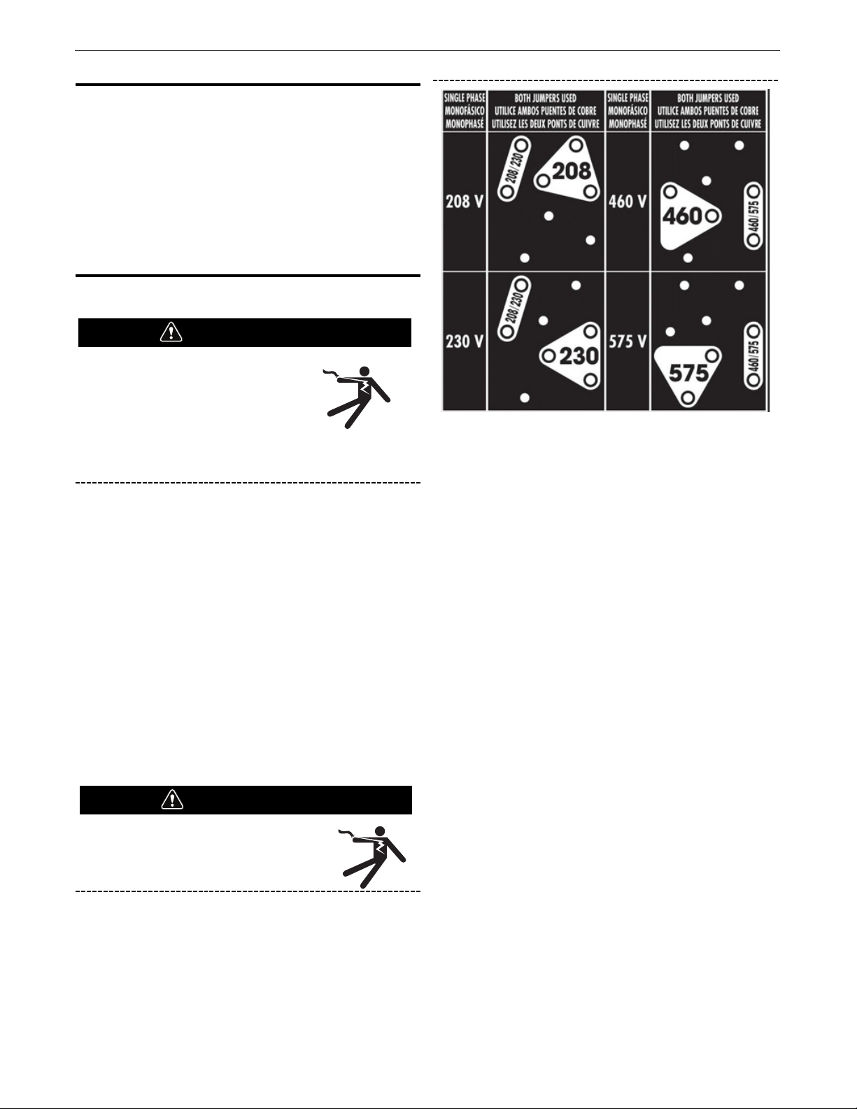
INPUT POWER, GROUNDING AND CONNECTION DIAGRAM
ELECTRIC SHOCK can kill.
• Do not touch electrically live parts
such as output terminals or internal
wiring.
• All input power must be electrically
disconnected before proceeding.
Make certain that the input power is
electrically disconnected before removing
the screw on the reconnect panel access
cover.
FIGURE A.1
WARNING
WARNING
The POWER MIG® 360MP is not equipped with 460/575 volt
60 Hz plug, an input cable or a receptacle.
1. Before starting the installation, check with the local power
company if there is any question about whether your power
supply is adequate for the voltage, amperes, phase, and
frequency specified on the welder rating plate. Also be sure the
planned installation will meet the U.S. National Electrical Code
and local code requirements. This welder may be operated from
a single phase source or from two lines of a three phase source.
2. POWER MIG® 360MP has multiple input voltages specified on
the nameplate. The unit is shipped connected for the 230
voltage. If the welder is to be operated on 208 voltage, it must
be reconnected according to the instructions in Figure A.1. For
higher voltage (460 & 575) reconnect per Figure A.1. Install
appropriate input cable per local and national electrical code.
3. The POWER MIG® 360MP is shipped with a 10 ft. NEMA R Type
6-50N three prong plug and cable connected to the welder. Obtain
a receptacle and mount it in a suitable location. Be sure it can be
reached by the plug on the input cable attached to the welder.
Mount with the grounding terminal at the top to allow the power
cable to hang down without bending.
A-4
INSTALLATIONPOWER MIG®360MP
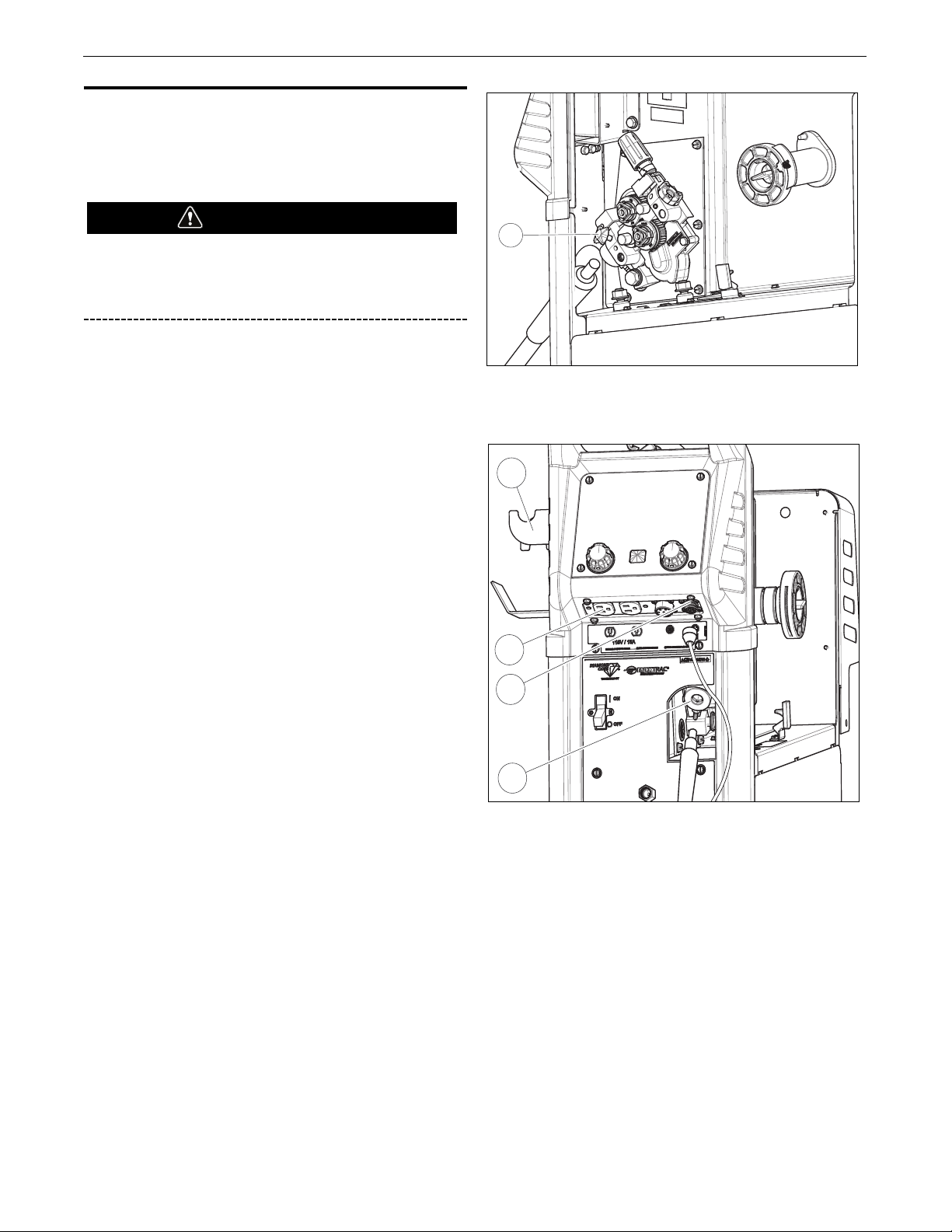
GUN AND CABLE INSTALLATION
The Magnum® PRO Curve 300 gun and cable provided with the
POWER MIG®360MP is factory installed with a liner for .035.045" (0.9-1.1 mm) electrode and an .035" (0.9 mm) contact tip.
Install the .045” tip (also provided) if this wire size is being used.
Turn the welder power switch off before installing gun and
cable.
FIGURE A.4
FIGURE A.5
3
WARNING
(See Figure A.4R_U2&)
1. Lay the cable out straight.
2. Unscrew the Hand Screw on the drive unit front end (inside
wire feed compartment - Item 3) until tip of screw no longer
protrudes into Gun Adapter (Item 2) opening as seen from
front of machine.
3. Insert the male end of gun cable into the Gun Adapter (Item 2)
through the opening in front panel. Make sure connector is
fully inserted and tighten Hand Screw.
4. Connect the Gun Trigger Connector from the gun and cable to
the mating Receptacle inside the compartment located on the
Front Panel (Item 1). Make sure that the keyways are aligned,
insert and tighten retaining ring.
5. A Coil Claw™ (Item 5) and tool holder are included with
POWER MIG® 360MP. To remove/reposition the tool holder,
remove the screw and insert. Reposition into desired slot on the
gas bottle upper bracket.
5
4
1
2

A-5
INSTALLATIONPOWER MIG®360MP
SHIELDING GAS
For necessary processes.
Customer must provide cylinder of appropriate type shielding gas
for the process being used.
A gas flow regulator, for Argon blend gas, an inlet gas hose, and a
regulator adapter are factory provided with the POWER MIG
®
360MP. When using 100% CO2, the regulator adapter will be
required to connect the regulator to the gas bottle.
CYLINDER may explode if damaged.
• Gas under pressure is explosive. Always
keep gas cylinders in an upright position
and always keep chained to undercarriage
or stationary support.
See American National Standard Z49.1, “Safety in Welding
and Cutting” published by the American Welding Society.
Install shielding gas supply as follows:
1. Set gas cylinder on rear platform of POWER MIG
®
360MP.
Hook chain in place to secure cylinder to rear of welder.
2. Remove the cylinder cap. Inspect the cylinder valves and
regulator for damaged threads, dirt, dust, oil or grease.
Remove dust and dirt with a clean cloth.
DO NOT ATTACH THE REGULATOR IF OIL, GREASE OR
DAMAGE IS PRESENT! Inform your gas supplier of this
condition. Oil or grease in the presence of high pressure
oxygen is explosive.
3. Stand to one side away from the outlet and open the cylinder
valve for an instant. This blows away any dust or dirt which
may have accumulated in the valve outlet.
Be sure to keep your face away from the valve outlet when
“cracking” the valve.
4. Attach the flow regulator to the cylinder valve and tighten the
union nut(s) securely with a wrench.
NOTE: If connecting to 100% CO2cylinder, the regulator
adapter provided must be installed between the regulator and
cylinder valve.
5. Attach one end of the inlet gas hose to the outlet fitting of the
flow regulator, the other end to the POWER MIG®360MP rear
fitting marked “Feeder” and tighten the union nuts securely
with a wrench.
6. Before opening the cylinder valve, turn the regulator adjusting
knob counterclockwise until the adjusting spring pressure is
released.
7. Standing to one side, open the cylinder valve slowly a fraction
of a turn. When the cylinder pressure gauge pointer stops
moving, open the valve fully.
Never stand directly in front of or behind the flow regulator
when opening the cylinder valve. Always stand to one side.
8. The flow regulator is adjustable. Adjust it to the flow rate
recommended for the procedure and process being used
before making the weld.
AUXILIARY POWER RECEPTACLES
This machine is equipped with 15Amp 120V receptacle with
15Amp Circuit Breaker. The receptacle is UL and CSA approved.
WARNING
WARNING
WARNING
B-1
OPERATIONPOWER MIG®360MP
OPERATION
SAFETY PRECAUTIONS
Read this entire section of operating instructions before operating
the machine.
ELECTRIC SHOCK can kill.
• Do not touch electrically live parts or
electrode with skin or wet clothing.
Insulate yourself from work and ground.
• Always wear dry insulating gloves.
FUMES AND GASES can be dangerous.
• Keep your head out of fumes.
• Use ventilation or exhaust to remove
fumes from breathing zone.
WELDING SPARKS can cause fire or explosion.
• Keep flammable material away.
• Do not weld on containers that have held
combustibles.
ARC RAYS can burn.
• Wear eye, ear, and body protection.
WELDING CAPABILITY
The POWER MIG®360MP is rated at 350 amps @ 31.5 volts, at a
40% duty cycle based on a ten minute cycle time for GMAW
processes. It is capable of higher duty cycles at lower output
currents and capable of up to 360 Amps at lower duty cycles.
LIMITATIONS
POWER MIG®360MP WILL NOT operate satisfactorily if powered
with a portable or in-plant generating system.
SETTING THE POWER MIG®360 MACHINE TO WELD
Power up the machine using the switch on the front of the
machine (See Item 8 of Figure B.1).
Allow machine to go through its booting stage. This will take
approximately 20 seconds.
The machine will take you to the Home Screen and display the
settings that were last input by the user.
To select a new welding process, press the middle Select Process
button
By turning the right knob, select the desired welding process from
the list. Press the right knob to make selection.
Welding Processes Screen Selections
• Manual Mig Mode
• (GMAW)
• Self-Shielded Flux Core (FCAW-S)
• Gas-Shielded Flux Core (FCAW-G)
• Spool Gun
• Push-Pull Gun
• TIG (GTAW)
• Stick (SMAW)
• Legacy Mode List
• Load
• Configuration
WARNING
PRODUCT DESCRIPTION
The POWER MIG® 360MP is a complete, semiautomatic multiprocess DC arc welding machine offering CV and CC DC welding
built to meet NEMA specifications. The standard machine is
equipped to weld CC-Stick, CC-GTAW, CV-FCAW, and synergic and
non-synergic CV-GMAW. GMAW-P, Pulse-on-Pulse® and Power
Mode® welding processes.
Other features include a 7” Digital User Interface with synergic
controls and memory capability, a 2” (51mm) O.D. wire reel
spindle with adjustable brake, integral gas cylinder mounting
undercarriage, an adjustable CO2 or Argon blend flow regulator
with cylinder pressure guage and inlet hose, a 15 ft. (4.6m)
Magnum PRO Curve 300 gun and cable, a 10 ft. (3.1m) power
cable and NEMA R Type 6-50N three prong plug and a 10 ft.
(3.1m) work cable and clamp.
The POWER MIG® 360MP features built in timer functions that
provide variable burnback control, a spot function, a selectable
4-step trigger interlock, and an adjustable ‘Run-In’ for wire
starting optimization. ARCFX™ technology comes standard and
provides a way tp graphically communicate instant feedback of
how the end user settings affect the weld outcome when adjusting
wire feed speed and voltage.
B-2
OPERATIONPOWER MIG®360MP
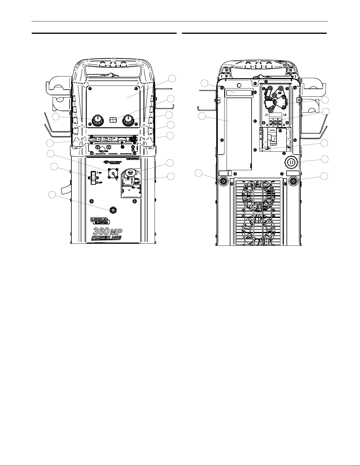
CASE FRONT CONTROLS
FIGURE B.1
CASE BACK CONTROLS
FIGURE B.2
2
9
10
8
12
1
3
4
5
6
7
11
1
2
7
3
4
5
6
8
1. Color LED Screen – Permits visualization of welding process and
parameters. The screen features a replaceable screen shield for
protecting against dust & dirt.
2. Back Button/Knob –
Rotate adjusts value, push to move back to
previous selection
3. Home Button – Returns the user to the Home Screen. At the Home
Screen, the user can select a welding process or the display
settings can be configured.
4. Select Button/Knob –
Rotate adjusts value, push confirms the
selected value or choice
5. Seven Pin Connector –
For attaching optional remote control
equipment. Includes auto-sensing remote control circuit.
6. Four Pin Trigger Receptacle – Permits triggering the machine for
MIG/FCAW or aluminum MIG. Connect the 4-pin connector present
on the welding gun to the receptacle.
7. Gun Connection – Permits attachment of a MIG welding gun.
Ensure the gun is fully seated into the brass receptacle.
8. Power Switch – Permits turning the machine on or off.
9. 115V receptacle
10. Six Pin Connector - Permits connecting a remote or TIG pedal.
11. Output Studs - Used to connect work and electrode leads.
12. TIG/Spool Gun Gas Connector - Used to connect gas to TIG torch
or a spool gun.
1. Decal – Serial number.
2. Decal – Input supply connection diagram
3. Reconnect Panel Assembly
4. Input Cable Connecting Block
5. Grounding – Input cable ground cable connector
6. Input power cord
7. Spool Gun/TIG Gas Solenoid Connector
8. MIG/Push-Pull Gas Solenoid Connector – Connection to gas
kkhose
B-3
OPERATIONPOWER MIG®360MP
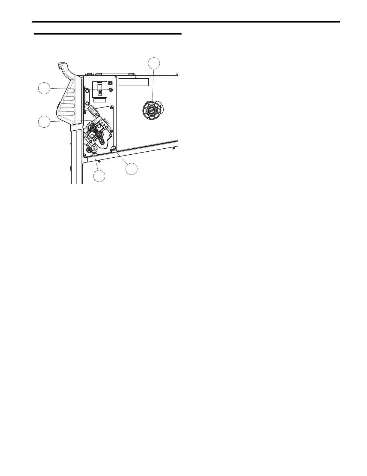
INTERNAL CONTROLS
FIGURE B.3
1
3
4
2
5
1. Wire Drive Tension Pressure Adjustment – Permits increasing or
decreasing the pressure applied to the top drive roll.
2. Wire Drive Spindle – Supports a 4-inch or 8-inch spool of wire.
The center wing-nut can be adjusted to increase tension on the
wire.
3. Negative Output Receptacle – Permits attaching a work lead,
electrode stinger, or the center wire drive polarity lead to DC
negative polarity. Rotate connector clockwise to lock into place.
4. Positive Output Receptacle – Permits attaching a work lead,
electrode stinger or the center wire drive polarity lead to DC positive
polarity. Rotate clockwise to lock into place.
5. Thermal Breaker – The POWER MIG® 360 features a resettable
15 amp circuit breaker. If the current conducted through the
breaker exceeds 15 amps for an extended period of time, the
breaker will open and require manual reset.
 Loading...