

Lincoln Electric Power MIG 260 Operator's Manual
Operator’s Manual
Register your machine:
www.lincolnelectric.com/register
Authorized Service and Distributor Locator:
www.lincolnelectric.com/locator
IM10464
| Issue D ate June-18
© Lincoln Global, Inc. All Rights Reserved.
For use with machines having Code Numbers:
12728
Save for future reference
Date Purchased
Code: (ex: 10859)
Serial: (ex: U1060512345)
Power MIG®260
Need Help? Call 1.888.935.3877
to talk to a Service Representative
Hours of Operation:
8:00 AM to 6:00 PM (ET) Mon. thru Fri.
After hours?
Use “Ask the Experts” at lincolnelectric.com
A Lincoln Service Representative will contact you
no later than the following business day.
For Service outside the USA:
Email: globalservice@lincolnelectric.com
THANK YOU FOR SELECTING
A QUALITY PRODUCT BY
LINCOLN ELEC TRIC.
PLEASE EXAMINE CARTON AND EQUIPMENT FOR
DAMAGE IMMEDIATELY
When this equipment is shipped, title passes to the purchaser
upon receipt by the carrier. Consequently, claims for material
damaged in shipment must be made by the purchaser against the
transportation company at the time the shipment is received.
SAFETY DEPENDS ON YOU
Lincoln arc welding and cutting equipment is designed and built
with safety in mind. However, your overall safety can be increased
by proper installation ... and thoughtful operation on your part.
DO NOT INSTALL, OPERATE OR REPAIR THIS EQUIPMENT
WITHOUT READING THIS MANUAL AND THE SAFETY
PRECAUTIONS CONTAINED THROUGHOUT. And, most importantly,
think before you act and be careful.
This statement appears where the information must be followed
exactly to avoid serious personal injury or loss of life.
This statement appears where the information must be followed
to avoid minor personal injury or damage to this equipment.
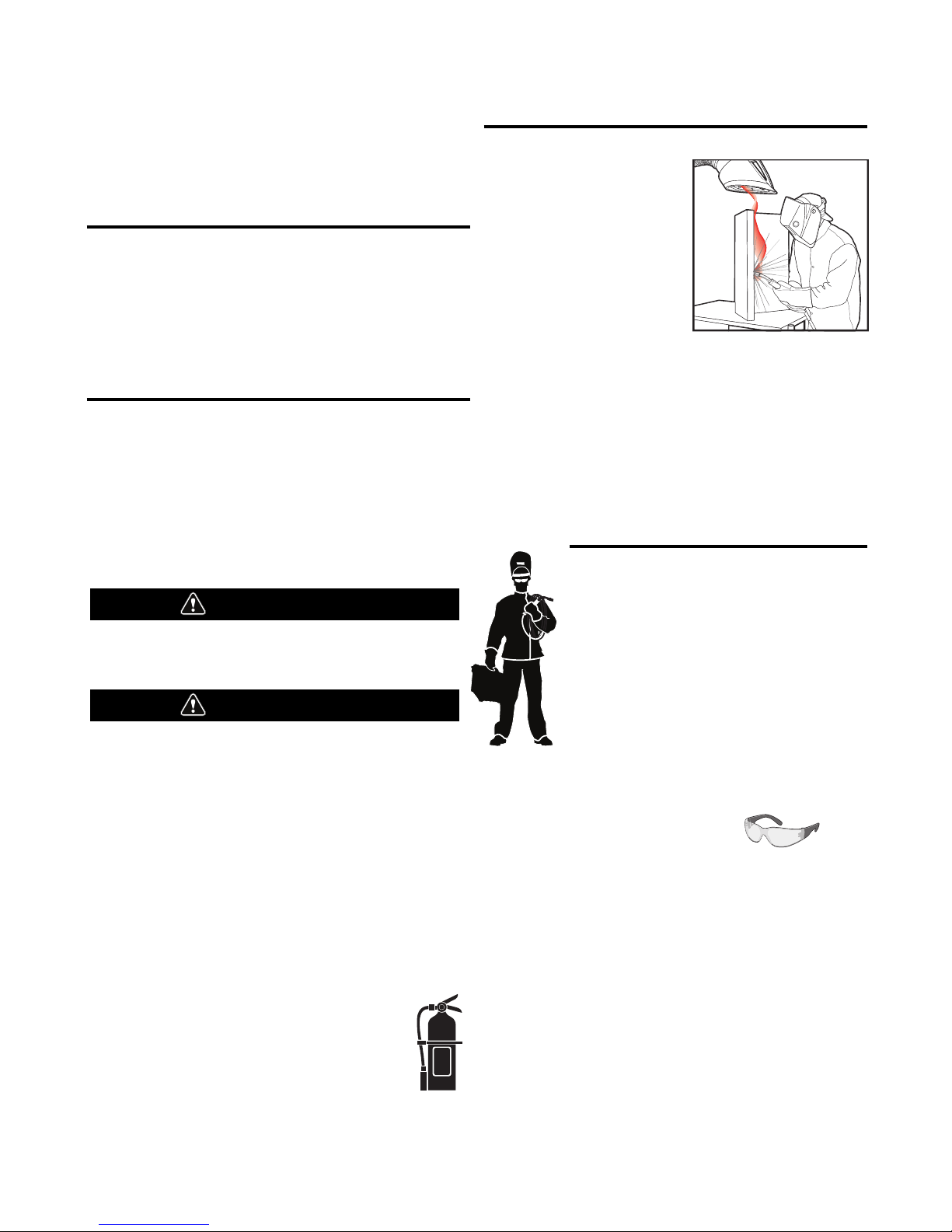
KEEP YOUR HEAD OUT OF THE FUMES.
DON’T get too close to the arc.
Use corrective lenses if necessary
to stay a reasonable distance
away from the arc.
READ and obey the Safety Data
Sheet (SDS) and the warning label
that appears on all containers of
welding materials.
USE ENOUGH VENTILATION or
exhaust at the arc, or both, to
keep the fumes and gases from
your breathing zone and the general area.
IN A LARGE ROOM OR OUTDOORS, natural ventilation may be
adequate if you keep your head out of the fumes (See below).
USE NATURAL DRAFTS or fans to keep the fumes away
from your face.
If you de velop unusual symptoms, see your supervisor.
Perhaps the welding atmosphere and ventilation system
should be checked.
WEAR CORRECT EYE, EAR &
BODY PROTECTION
PROTECT your eyes and face with welding helmet
properly fitted and with proper grade of filter plate
(See ANSI Z49.1).
PROTECT your body from welding spatter and arc
flash with protective clothing including woolen
clothing, flame-proof apron and gloves, leather
leggings, and high boots.
PROTECT others from splatter, flash, and glare
with protective screens or barriers.
IN SOME AREAS, protection from noise may be appropriate.
BE SURE protective equipment is in good condition.
Also, wear safety glasses in work area
AT ALL TIMES.
SPECIAL SITUATIONS
DO NOT WELD OR CUT containers or materials which previously
had been in contact with hazardous substances unless they are
properly cleaned. This is extremely dangerous.
DO NOT WELD OR CUT painted or plated parts unless special
precautions with ventilation have been taken. They can release
highly toxic fumes or gases.
Additional precautionary measures
PROTECT compressed gas cylinders from excessive heat,
mechanical shocks, and arcs; fasten cylinders so they cannot fall.
BE SURE cylinders are never grounded or part of an
electrical circuit.
REMOVE all potential fire hazards from welding area.
ALWAYS HAVE FIRE FIGHTING EQUIPMENT READY FOR
IMMEDIATE USE AND KNOW HOW TO USE IT.
WARNING
CAUTION
Safety 01 of 04 - 5/16/2018
SECTION A:
WARNINGS
CALIFORNIA PROPOSITION 65 WARNINGS
WARNING: Breathing diesel engine exhaust
exposes you to chemicals known to the State
of California to cause cancer and birth defects,
or other reproductive harm.
• Always start and operate the engine in a
well-ventilated area.
• If in an exposed area, vent the exhaust to the outside.
• Do not modify or tamper with the exhaust system.
• Do not idle the engine except as necessary.
For more information go to
www.P65 warnings.ca.gov/diesel
WARNING: This product, when used for welding or
cutting, produces fumes or gases which contain
chemicals known to the State of California to cause
birth defects and, in some cases, cancer. (California
Health & Safety Code § 25249.5 et seq.)
WARNING: Cancer and Reproductive Harm
www.P65warnings.ca.gov
ARC WELDING CAN BE HAZARDOUS. PROTECT
YOURSELF AND OTHERS FROM POSSIBLE SERIOUS
INJURY OR DEATH. KEEP CHILDREN AWAY.
PACEMAKER WEARERS SHOULD CONSULT WITH
THEIR DOCTOR BEFORE OPERATING.
Read and understand the following safety highlights. For
additional safety information, it is strongly recommended
that you purchase a copy of “Safety in Welding & Cutting ANSI Standard Z49.1” from the American Welding Society,
P.O. Box 351040, Miami, Florida 33135 or CSA Standard
W117.2-1974. A Free copy of “Arc Welding Safety” booklet
E205 is available from the Lincoln Electric Company,
22801 St. Clair Avenue, Cleveland, Ohio 44117-1199.
BE SURE THAT ALL INSTALLATION, OPERATION,
MAINTENANCE AND REPAIR PROCEDURES ARE
PERFORMED ONLY BY QUALIFIED INDIVIDUALS.
FOR ENGINE POWERED
EQUIPMENT.
1.a. Turn the engine off before troubleshooting
and maintenance work unless the
maintenance work requires it to be running.
1.b. Operate engines in open, well-ventilated areas or vent the engine
exhaust fumes outdoors.
1.c. Do not add the fuel near an open flame welding
arc or when the engine is running. Stop the
engine and allow it to cool before refueling to
prevent spilled fuel from vaporizing on contact
with hot engine parts and igniting. Do not spill fuel when filling
tank. If fuel is spilled, wipe it up and do not start engine until
fumes have been eliminated.
1.d. Keep all equipment safety guards, covers
and devices in position and in good repair.
Keep hands, hair, clothing and tools away
from V-belts, gears, fans and all other
moving parts when starting, operating or
repairing equipment.
1.e. In some cases it may be necessary to remove safety guards to
perform required maintenance. Remove guards only when
necessary and replace them when the maintenance requiring
their removal is complete. Always use the greatest care when
working near moving parts.
1.f. Do not put your hands near the engine fan. Do not attempt to
override the governor or idler by pushing on the throttle control
rods while the engine is running.
1.g. To prevent accidentally starting gasoline engines while turning
the engine or welding generator during maintenance work,
disconnect the spark plug wires, distributor cap or magneto wire
as appropriate.
1.h. To avoid scalding, do not remove the radiator
pressure cap when the engine is
hot.
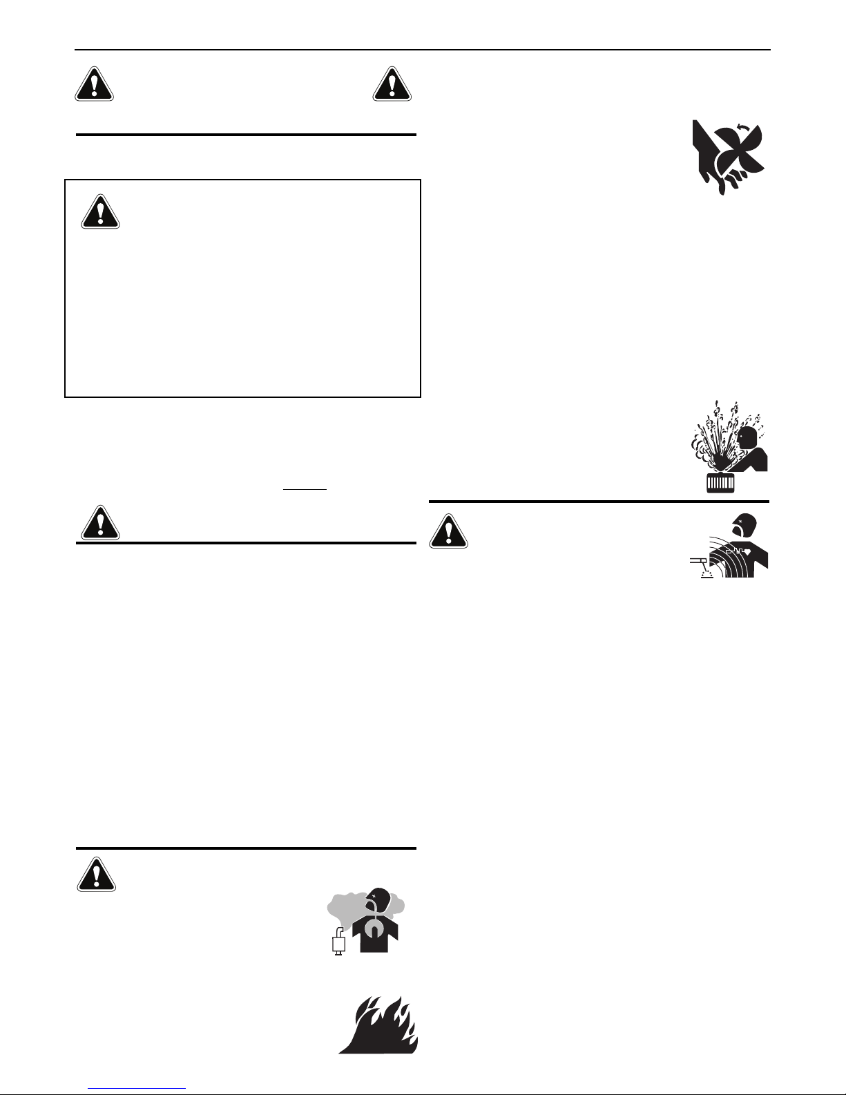
ELECTRIC AND
MAGNETIC FIELDS MAY
BE DANGEROUS
2.a. Electric current flowing through any conductor
causes localized Electric and Magnetic Fields (EMF).
Welding current creates EMF fields around welding cables
and welding machines
2.b. EMF fields may interfere with some pacemakers, and
welders having a pacemaker should consult their physician
before welding.
2.c. Exposure to EMF fields in welding may have other health effects
which are now not known.
2.d. All welders should use the following procedures in order to
minimize exposure to EMF fields from the welding circuit:
2.d.1. Route the electrode and work cables together - Secure
them with tape when possible.
2.d.2. Never coil the electrode lead around your body.
2.d.3. Do not place your body between the electrode and work
cables. If the electrode cable is on your right side, the
work cable should also be on your right side.
2.d.4. Connect the work cable to the workpiece as close as possible to the area being welded.
2.d.5. Do not work next to welding power source.
SAFETY
Safety 02 of 04 - 5/16/2018
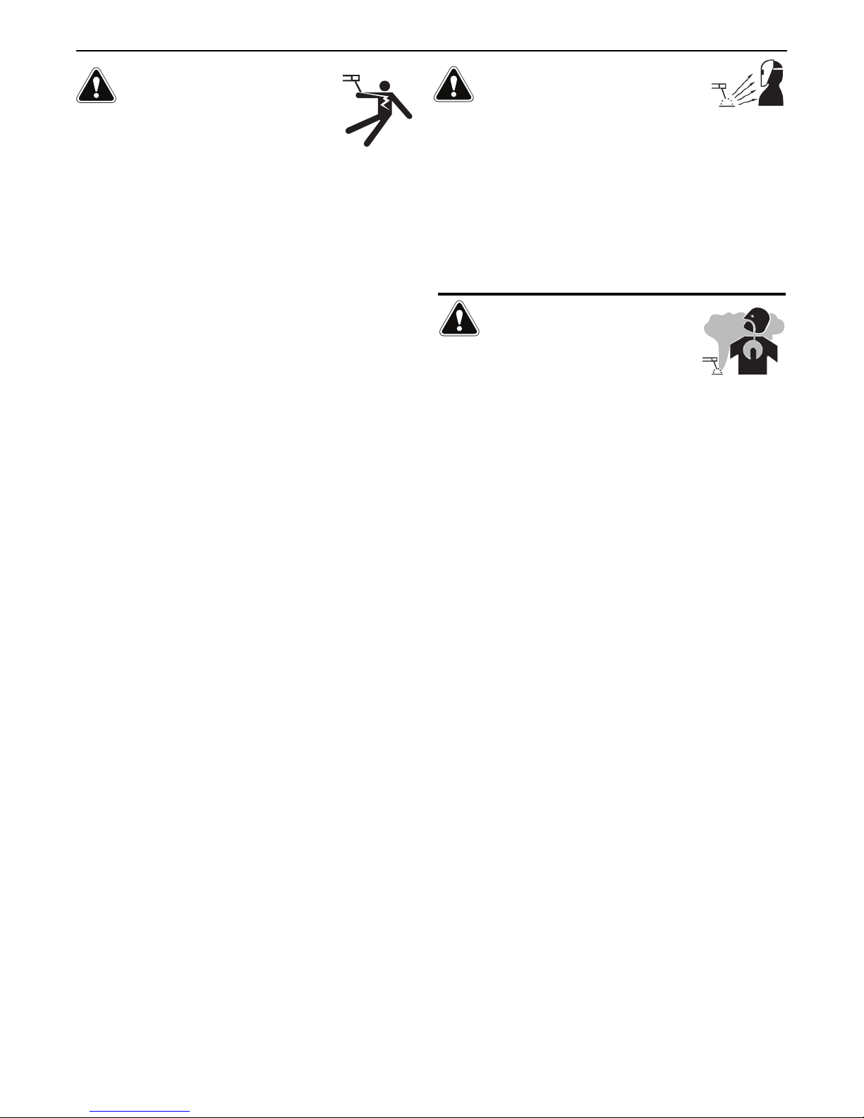
ELECTRIC SHOCK
CAN KILL.
3.a. The electrode and work (or ground) circuits are
electrically “hot” when the welder is on. Do
not touch these “hot” parts with your bare skin or wet clothing.
Wear dry, hole-free gloves to insulate hands.
3.b. Insulate yourself from work and ground using dry insulation.
Make certain the insulation is large enough to cover your full area
of physical contact with work and ground.
In addition to the normal safety precautions, if
welding must be performed under electrically
hazardous conditions (in damp locations or while
wearing wet clothing; on metal structures such as
floors, gratings or scaffolds; when in cramped
positions such as sitting, kneeling or lying, if there
is a high risk of unavoidable or accidental contact
with the workpiece or ground) use the following
equipment:
• Semiautomatic DC Constant Voltage (Wire) Welder.
• DC Manual (Stick) Welder.
• AC Welder with Reduced Voltage Control.
3.c. In semiautomatic or automatic wire welding, the electrode,
electrode reel, welding head, nozzle or semiautomatic welding
gun are also electrically “hot”.
3.d. Always be sure the work cable makes a good electrical
connection with the metal being welded. The connection should
be as close as possible to the area being welded.
3.e. Ground the work or metal to be welded to a good electrical (earth)
ground.
3.f. Maintain the electrode holder, work clamp, welding cable and
welding machine in good, safe operating condition. Replace
damaged insulation.
3.g. Never dip the electrode in water for cooling.
3.h. Never simultaneously touch electrically “hot” parts of electrode
holders connected to two welders because voltage
between the
two can be the total of the open circuit voltage of both
welders.
3.i. When working above floor level, use a safety belt to protect
yourself from a fall should you get a shock.
3.j. Also see It ems 6.c. and 8.
ARC RAYS CAN BURN.
4.a. Use a shield with the proper filter and cover plates to protect your
eyes from sparks and the rays of the arc when welding or
observing open arc welding. Headshield and filter lens should
conform to ANSI Z87. I standards.
4.b. Use suitable clothing made from durable flame-resistant material
to protect your skin and that of your helpers from the arc rays.
4.c. Protect other nearby personnel with suitable, non-flammable
screening and/or warn them not to watch the arc nor expose
themselves to the arc rays or to hot spatter or metal.
FUMES AND GASES
CAN BE DANGEROUS.
5.a. Welding may produce fumes and gases
hazardous to health. Avoid breathing these
fumes and gases. When welding, keep your head out of the fume.
Use enough ventilation and/or exhaust at the arc to keep fumes
and gases away from the breathing zone. When welding
hardfacing (see instructions on container or SDS)
or on lead or cadmium plated steel and other
metals or coatings which produce highly toxic
fumes, keep exposure as low as possible and
within applicable OSHA PEL and ACGIH TLV limits
using local exhaust or mechanical ventilation
unless exposure assessments indicate otherwise.
In confined spaces or in some circumstances,
outdoors, a respirator may also be required.
Additional precautions are also required when
welding
on galvanized steel.
5. b. The operation of welding fume control equipment is affected by
various factors including proper use and positioning of the
equipment, maintenance of the equipment and the specific
welding procedure and application involved. Worker exposure
level should be checked upon installation and periodically
thereafter to be certain it is within applicable OSHA PEL and
ACGIH TLV limits.
5.c. Do not weld in locations near chlorinated hydrocarbon vapors
coming from degreasing, cleaning or spraying operations. The
heat and rays of the arc can react with solvent vapors to form
phosgene, a highly toxic gas, and other irritating products.
5.d. Shielding gases used for arc welding can displace air and
cause
injury or death. Always use enough ventilation, especially in
confined areas, to insure breathing air is safe.
5.e. Read and understand the manufacturer’s instructions for this
equipment and the consumables to be used, including the
Safety Data Sheet (SDS) and follow your employer’s safety
practices. SDS forms are available from your welding
distributor or from the manufacturer.
5.f. Also see item 1.b.
SAFETY
Safety 03 of 04 - 5/16/2018
WELDING AND CUTTING
SPARKS CAN CAUSE
FIRE OR EXPLOSION.
6.a. Remove fire hazards from the welding area. If
this is not possible, cover them to prevent the welding sparks
from starting a fire. Remember that welding sparks and hot
materials from welding can easily go through small cracks and
openings to adjacent areas. Avoid welding near hydraulic lines.
Have a fire extinguisher readily available.
6.b. Where compressed gases are to be used at the job site, special
precautions should be used to prevent hazardous situations.
Refer to “Safety in Welding and Cutting” (ANSI Standard Z49.1)
and the operating information for the equipment being used.
6.c. When not welding, make certain no part of the electrode circuit is
touching the work or ground. Accidental contact can cause
overheating and create a fire hazard.
6.d. Do not heat, cut or weld tanks, drums or containers until the
proper steps have been taken to insure that such procedures
will not cause flammable or toxic vapors from substances inside.
They can cause an explosion even though they have been
“cleaned”. For information, purchase “Recommended Safe
Practices for the Preparation for Welding and Cutting of
Containers and Piping That Have Held Hazardous Substances”,
AWS F4.1 from the American Welding Society
(see address above).
6.e. Vent hollow castings or containers before heating, cutting or
welding. They may explode.
6.f. Sparks and spatter are thrown from the welding arc. Wear oil free
protective garments such as leather gloves, heavy shirt, cuffless
trousers, high shoes and a cap over your hair. Wear ear plugs
when welding out of position or in confined places. Always wear
safety glasses with side shields when in a welding area.
6.g. Connect the work cable to the work as close to the welding area
as practical. Work cables connected to the building framework or
other locations away from the welding area increase the
possibility of the welding current passing through lifting chains,
crane cables or other alternate circuits. This can create fire
hazards or overheat lifting chains or cables until they fail.
6.h. Also see item 1.c.
6.I. Read and follow NFPA 51B “Standard for Fire Prevention During
Welding, Cutting and Other Hot Work”, available from NFPA, 1
Batterymarch Park, PO box 9101, Quincy, MA 022690-9101.
6.j. Do not use a welding power source for pipe thawing.
CYLINDER MAY EXPLODE IF
DAMAGED.
7.a. Use only compressed gas cylinders containing
the correct shielding gas for the process used
and properly operating regulators designed for
the gas and pressure used. All hoses, fittings,
etc. should be suitable for the application and
maintained in good condition.
7.b. Always keep cylinders in an upright position securely chained to
an undercarriage or fixed support.
7.c. Cylinders should be located:
• Away from areas where they may be struck or subjected
to physical damage.
• A safe distance from arc welding or cutting operations
and any other source of heat, sparks, or flame.
7.d. Never allow the electrode, electrode holder or any other
electrically “hot” parts to touch a cylinder.
7.e. Keep your head and face away from the cylinder valve outlet
when opening the cylinder valve.
7.f. Valve protection caps should always be in place and hand tight
except when the cylinder is in use or connected for use.
7.g. Read and follow the instructions on compressed gas cylinders,
associated equipment, and CGA publication P-l, “Precautions for
Safe Handling of Compressed Gases in Cylinders,” available from
the Compressed Gas Association, 14501 George Carter Way
Chantilly, VA 20151.
FOR ELECTRICALLY
POWERED EQUIPMENT.
8.a. Turn off input power using the disconnect
switch at the fuse box before working on
the equipment.
8.b. Install equipment in accordance with the U.S. National Electrical
Code, all local codes and the manufacturer’s recommendations.
8.c. Ground the equipment in accordance with the U.S. National
Electrical Code and the manufacturer’s recommendations.
Refer to
http://www.lincolnelectric.com/safety
for additional safety information.
SAFETY
Safety 04 of 04 - 5/16/2018

PRÉCAUTIONS DE SÛRETÉ
Pour
votre propre protection lire et observer toutes les
instructions et les précautions de sûreté specifiques qui parraissent dans ce manuel aussi bien que les précautions de
sûreté générales suivantes:
Sûreté Pour Soudage A L’Arc
1. Protegez-vous contre la secousse électrique:
a. Les circuits à l’électrode et à la piéce sont sous ten-
sion quand la machine à souder est en marche. Eviter
toujours tout contact entre les parties sous tension et
la peau nue ou les vétements mouillés. Porter des
gants secs et sans trous pour isoler les mains.
b. Faire trés attention de bien s’isoler de la masse quand
on soude dans des endroits humides, ou sur un
plancher metallique ou des grilles metalliques, principalement dans les positions assis ou couché
pour lesquelles une grande partie du corps peut être
en contact avec la masse.
c. Maintenir le porte-électrode, la pince de masse, le
câble de soudage et la machine à souder en bon et sûr
état defonctionnement.
d.Ne jamais plonger le porte-électrode dans l’eau pour le
refroidir.
e. Ne jamais toucher simultanément les parties sous ten-
sion des porte-électrodes connectés à deux machines
à souder parce que la tension entre les deux pinces
peut être le total de la tension à vide des deux
machines.
f. Si on utilise la machine à souder comme une source
de courant pour soudage semi-automatique, ces precautions pour le porte-électrode s’applicuent aussi au
pistolet de soudage.
2. Dans le cas de travail au dessus du niveau du sol, se protéger contre les chutes dans le cas ou on recoit un choc.
Ne jamais enrouler le câble-électrode autour de n’importe
quelle partie du corps.
3. Un coup d’arc peut être plus sévère qu’un coup de soliel,
donc:
a. Utiliser un bon masque avec un verre filtrant appro-
prié ainsi qu’un verre blanc afin de se protéger les
yeux du rayonnement de l’arc et des projections
quand on soude ou quand on regarde l’arc.
b. Porter des vêtements convenables afin de protéger la
peau de soudeur et des aides contre le rayonnement
de l‘arc.
c. Protéger l’autre personnel travaillant à proximité au
soudage à l’aide d’écrans appropriés et non-inflammables.
4. Des gouttes de laitier en fusion sont émises de l’arc de
soudage. Se protéger avec des vêtements de protection
libres de l’huile, tels que les gants en cuir, chemise
épaisse, pantalons sans revers, et chaussures montantes.
5. Toujours porter des lunettes de sécurité dans la zone de
soudage. Utiliser des lunettes avec écrans lateraux dans
les zones où l’on pique le laitier.
6. Eloigner les matériaux inflammables ou les recouvrir afin
de prévenir tout risque d’incendie dû aux étincelles.
7. Quand on ne soud
e pas, poser la pince à une endroit
isolé de la masse. Un court-circuit accidental peut provoquer un échauffement et un risque d’incendie.
8. S’assurer que la masse est connectée le plus prés possible de la zone de travail qu’il est pratique de le faire. Si on
place la masse sur la charpente de la construction ou
d’autres endroits éloignés de la zone de travail, on augmente le risque de voir passer le courant de soudage par
les chaines de levage, câbles de grue, ou autres circuits.
Cela peut provoquer des risques d’incendie ou d’echauffement des chaines et des câbles jusqu’à ce qu’ils se
rompent.
9. Assurer une ventilation suffisante dans la zone de
soudage. Ceci est particuliérement important pour le
soudage de tôles galvanisées plombées, ou cadmiées ou
tout autre métal qui produit des fumeés toxiques.
10. Ne pas souder en présence de vapeurs de chlore
provenant d’opérations de dégraissage, nettoyage ou pistolage. La chaleur ou les rayons de l’arc peuvent réagir
avec les vapeurs du solvant pour produire du phosgéne
(gas fortement toxique) ou autres produits irritants.
11. Pour obtenir de plus amples renseignements sur la
sûreté, voir le code “Code for safety in welding and cutting” CSA Standard W 117.2-1974.
PRÉCAUTIONS DE SÛRETÉ POUR
LES MACHINES À SOUDER À
TRANSFORMATEUR ET À
REDRESSEUR
1. Relier à la terre le chassis du poste conformement au
code de l’électricité et aux recommendations du fabricant. Le dispositif de montage ou la piece à souder doit
être branché à une bonne mise à la terre.
2. Autant que possible, I’installation et l’entretien du poste
seront effectués par un électricien qualifié.
3. Avant de faires des travaux à l’interieur de poste, la
debrancher à l’interrupteur à la boite de fusibles.
2

3
TABLE OF CONTENTS
INSTALLATION .............................................................................................................................................SECTION A
TECHNICAL SPECIFICATIONS ....................................................................................................................................A-1
UNCRATING ............................................................................................................................................................A-2
PRODUCT DESCRIPTION ............................................................................................................................................A-2
LOCATION ............................................................................................................................................................A-2
TILTING ............................................................................................................................................................A-2
OUTPUT POLARITY CONNECTIONS.............................................................................................................................A-2
INPUT POWER, GROUNDING AND CONNECTION DIAGRAM..........................................................................................A-2
GUN AND CABLE INSTALLATION ................................................................................................................................A-2
SHIELDING GAS .........................................................................................................................................................A-2
AUXILIARY POWER RECEPTACLES..............................................................................................................................A-2
OPERATION ................................................................................................................................................SECTION B
RECOMMENDED PROCESSES AND EQUIPMENT .........................................................................................................B-1
WELDING CAPABILITY................................................................................................................................................B-1
LIMITATIONS ............................................................................................................................................................B-1
GRAPHIC SYMBOLS USED IN THIS MANUAL...............................................................................................................B-1
CASE FRONT CONTROLS ...........................................................................................................................................B-2
CASE BACK CONTROLS .............................................................................................................................................B-2
INTERNAL CONTROLS................................................................................................................................................B-3
WIRE SIZE CONVERSION PARTS.................................................................................................................................B-4
PROCEDURE FOR CHANGING DRIVE AND IDLE ROLL SETS .........................................................................................B-4
WIRE REEL LOADING - READI REELS, SPOOLS OR COILS ...........................................................................................B-4
TO START THE WELDER ............................................................................................................................................B-5
FEEDING WIRE ELECTRODE .......................................................................................................................................B-5
IDLE ROLL PRESSURE SETTING .................................................................................................................................B-5
WIRE DRIVE CONFIGURATION.....................................................................................................................................B-6
DISPLAY OPERATION: ................................................................................................................................................B-7
MAKING A WELD........................................................................................................................................................B-9
AVOIDING WIRE FEEDING PROBLEMS ........................................................................................................................B-9
FAN CONTROL...........................................................................................................................................................B-9
INPUT LINE VOLTAGE PROTECTION............................................................................................................................B-9
WIRE FEED OVERLOAD PROTECTION .........................................................................................................................B-9
WELDING THERMAL OVERLOAD PROTECTION............................................................................................................B-9
OVERCURRENT PROTECTION .....................................................................................................................................B-9
OPTIONS / ACCESSORIES.............................................................................................................................SECTION C
DRIVE ROLL KITS.......................................................................................................................................................C-1
ALTERNATIVE MAGNUM GMAW GUN AND CABLE ASSEMBLIES..................................................................................C-1
MAGNUM GUN CONNECTION KIT (OPTIONAL K466-6) ................................................................................................C-1
SPOOL GUN ............................................................................................................................................................C-1
CONNECTING THE SPOOL GUN TO THE POWER MIG® 260 ........................................................................................C-2
MAKING A WELD WITH THE SPOOL GUN ....................................................................................................................C-2
MAKING A WELD WITH THE MAGNUM SG SPOOL GUN ...............................................................................................C-3
CONNECTING THE PUSH-PULL GUN..........................................................................................................................C-3
WELDING WITH THE PUSH-PULL GUN........................................................................................................................C-3
PUSH-PULL CALIBRATION..........................................................................................................................................C-3
MAINTENANCE .............................................................................................................................................SECTION D
GENERAL MAINTENANCE...........................................................................................................................................D-1
DRIVE ROLLS AND GUIDE PLATES..............................................................................................................................D-1
CONTACT TIP AND GAS NOZZLE INSTALLATION.........................................................................................................D-1
GUN TUBES AND NOZZLES........................................................................................................................................D-1
GUN CABLE CLEANING .............................................................................................................
.................................D-1
LINER REMOVAL AND REPLACEMENT........................................................................................................................D-1
LINER REMOVAL, INSTALLATION AND TRIMMING INSTRUCTIONS FOR MAGNUM
®
PRO 250L....................................D-1
GUN HANDLE DISASSEMBLY .....................................................................................................................................D-2
TROUBLESHOOTING......................................................................................................................................SECTION E
DIAGRAMS ................................................................................................................................SECTION G
PARTS LIST...............................................................................................PARTS.LINCOLNELECTRIC.COM
CONTENT/DETAILS MAY BE CHANGED OR UPDATED WITHOUT NOTICE. FOR MOST CURRENT INSTRUCTION
MANUALS, GO TO PARTS.LINCOLNELECTRIC.COM

A-1
INSTALLATIONPOWER MIG®260
TECHNICAL SPECIFICATIONS – POWER MIG®260
Input Ampere
Input Voltage Fuse or Breaker Rating On
Frequency (Hz) Size (Super Lag) Nameplate
208/60 60 59A 8
230/60 60 55A 10
460/60 30 27A 14
575/60 25 21A 14
INPUT – SINGLE PHASE ONLY
RATED OUTPUT
OUTPUT*
RECOMMENDED INPUT WIRE AND FUSE SIZES
Height Width Depth Weight
37.25 in.
19.15 in.
40.4 in.
247 Lbs
946.15 mm 486 mm 1026 mm 112 kgs
PHYSICAL DIMENSIONS
Wire Speed 50 – 700 IPM (1.27 – 17.8 m/minute)
WIRE SPEED RANGE
Standard Voltage/Phase/Frequency
Input Current @ 200 Amp Rated Output Input Current @ 250 Amp Rated Output
208/230/460/575/1/60 Hz 50/46/23/19 Amps 56/53/27/22 Amps
Duty Cycle Amps Volts at Rated Amperes
40% 250 Amps 26.5 Volts
60% 200 Amps 24 Volts
100% 145 Amps 21.5 Volts
Welding Current Range (Continuous) Maximum Open Circuit Voltage Welding Voltage Range
30 – 300 Amps 40 Volts 10-28 Volts
TEMPERATURE RANGES
STORAGE TEMPERATURE RANGE
-40°F to 185°F(-40°C to +85°C)
OPERATING TEMPERATURE RANGE
-4°F to 104°F(-20°C to +40°C)
* With 115V receptacle loaded to 15A.
Type S, SO, ST, STO or extra
hard usage input cord
AWG (IEC) Sizes
A-2
INSTALLATIONPOWER MIG®260
INSTALLATION
Read entire installation section before starting
installation.
Safety Precautions
ELECTRIC SHOCK can kill.
• Only qualified personnel should
perform this installation.
• Only personnel that have read and
understood the POWER MIG
®
260
Operator’s Manual should install and
operate this equipment.
• Machine must be grounded per any national, local or
other applicable electrical codes.
• The POWER MIG
®
260 power switch is to be in the OFF
position when installing work cable and gun and when
connecting other equipment.
UNCRATING THE POWER MIG®260
Cut banding and lift off cardboard carton. Cut banding holding the
machine to the skid. Remove foam and corrugated packing
material. Untape accessories from Gas Bottle Platform. Unscrew
the two wood screws (at the Gas Bottle Platform) holding the
machine to the skid. Roll the machine off the skid assembly.
PRODUCT DESCRIPTION
The POWER MIG®260 is a complete semiautomatic constant
voltage DC arc welding machine built to meet NEMA specifications. It combines a constant voltage power source and a
constant speed wire feeder with a microcomputer-based
controller to form a reliable high performance welding system. A
simple control scheme, consisting of continuous full range voltage
and wire feed speed controls, provides versatility with ease of use
and accuracy. The POWER MIG
®
260 is Spool and Push Pull Gun
ready and includes a second Gas Solenoid for spool gun use. Refer
to Accessories Section for applicable push pull and spool guns.
Other features include a 7” Digital User Interface with synergic
controls and memory capability, a 2” (51 mm) O.D. wire reel
spindle with adjustable brake, an integral gas cylinder mounting
under carriage, an adjustable CO2or Argon blend flow regulator
with cylinder pressure gauge and inlet hose, a 15 ft (4.6 m)
Magnum®PRO 250L GMAW gun and cable, a 10ft. (3.1 m) power
cable with NEMA R Type 6-50N three prong plug and a 10 ft
(3.1 m) work cable with clamp.
The POWER MIG®260 features built in timer functions that
provide variable burnback control, a spot function, a selectable 4step trigger interlock and adjustable “Run-In” for wire starting
optimization. ARCFX™ technology comes standard and provides a
way to graphically communicate instant feedback of how the end
user settings affect the weld outcome when adjusting wire feed
speed and voltage.
LOCATION
Locate the welder in a dry location where there is free circulation
of clean air into the louvers in the back and the louvers out the
front. A location that minimizes the amount of smoke and dirt
drawn into the rear louvers reduces the chance of dirt
accumulation that can block air passages and cause overheating.
TILTING
Each machine must be placed on a secure, level surface, either
directly or on a recommended cart. The machine may topple over
if this precaution is not followed.
OUTPUT POLARITY CONNECTIONS
The welder, as shipped from the factory, is connected for
electrode positive (+) polarity. This is the normal polarity for
GMAW.
If negative (–) polarity is required, interchange the connection of
the two cables located in the wire drive compartment near the
front panel. The electrode cable, which is attached to the wire
drive, is to be connected to the negative (–) labeled terminal and
the work lead, which is attached to the work clamp, is to be
connected to the positive (+) labeled terminal.
INPUT POWER, GROUNDING AND CONNECTION DIAGRAM
ELECTRIC SHOCK can kill.
• Do not touch electrically live parts such
as output terminals or internal wiring.
• All input power must be electrically
disconnected before proceeding.
The Power MIG 260 is not equipped with 460/575 volt 60 Hz plug,
an input cable or a receptacle.
1. Before starting the installation, check with the local power
company if there is any question about whether your power
supply is adequate for the voltage, amperes, phase, and
frequency specified on the welder rating plate. Also be sure
the planned installation will meet the U.S. National Electrical
Code and local code requirements. This welder may be
operated from a single phase line or from one phase of a two
or three phase line.
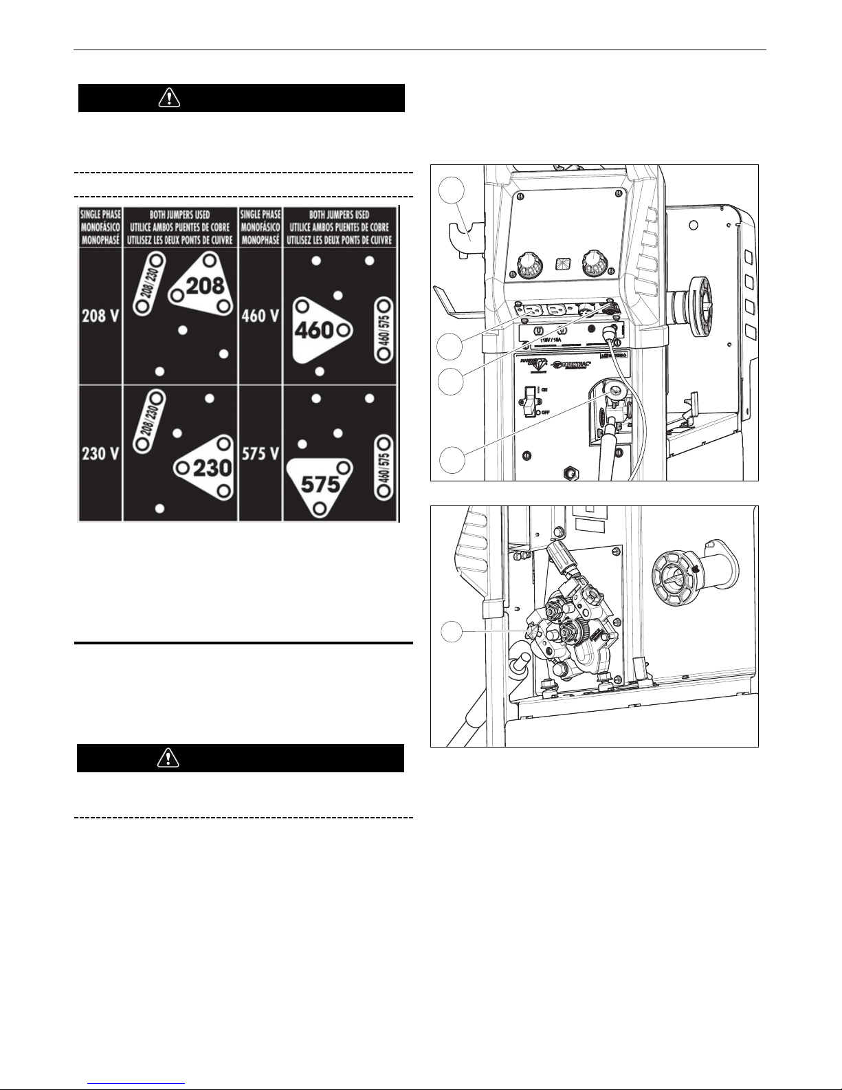
2. Power MIG 260 has multiple input voltages specified on the
nameplate. The unit is shipped connected for the 230 voltage.
If the welder is to be operated on 208 voltage, it must be
reconnected according to the instructions in Figure A.1. For
higher voltage (460 & 575) reconnect per Figure A.1. Install
appropriate input cable per local and national electrical code.
WARNING
WARNING
A-3
INSTALLATIONPOWER MIG®260
Make certain that the input power is electrically
disconnected before removing the screw on the reconnect
panel access cover.
FIGURE A.1
3.
3. The POWER MIG 260 is shipped with a 10 ft. NEMA R Type 650N three prong plug and cable connected to the welder.
Obtain a receptacle and mount it in a suitable location. Be
sure it can be reached by the plug on the input cable attached
to the welder. Mount with the grounding terminal at the top to
allow the power cable to hang down without bending.
GUN AND CABLE INSTALLATION
The Magnum®PRO 250L gun and cable provided with the
POWER MIG®260 is factory installed with a liner for .035-.045"
(0.9-1.1 mm) electrode and an .035" (0.9 mm) contact tip. Install
the .045” tip (also provided) if this wire size is being used.
Turn the welder power switch off before installing gun and
cable.
(See Figure A.4)
1. Lay the cable out straight.
2. Unscrew the Hand Screw on the drive unit front end (inside
wire feed compartment - Item 3) until tip of screw no longer
protrudes into Gun Adapter opening as seen from front of
machine. (See Figure A.4)
3. Insert the male end of gun cable into the Gun Adapter (Item 2)
through the opening in front panel. Make sure connector is
fully inserted and tighten Hand Screw.
4. Connect the Gun Trigger Connector from the gun and cable to
the mating Receptacle inside the compartment located left on
the Front Panel - Item 1. Make sure that the keyways are
aligned, insert and tighten retaining ring.
FIGURE A.4
FIGURE A.5
A Coil Claw™ [Fig A.4 (Item 5)] and tool holder are included with
Power MIG 260. To remove/reposition the tool holder, remove the
screw and insert. Reposition into desired slot on the gas bottle
upper bracket (G9040).
3
WARNING
2
1
4
5
WARNING

A-4
INSTALLATIONPOWER MIG®260
SHIELDING GAS
[For Gas Metal Arc Welding(GMAW) Processes]
Customer must provide cylinder of appropriate type shielding gas
for the process being used.
A gas flow regulator, for Argon blend gas, an inlet gas hose, and a
regulator adapter are factory provided with the POWER MIG®260.
When using 100% CO2, the regulator adapter will be required to
connect the regulator to the gas bottle.
CYLINDER may explode if damaged.
• Gas under pressure is explosive. Always
keep gas cylinders in an upright position
and always keep chained to undercarriage
or stationary support.
See American National Standard Z49.1, “Safety in Welding
and Cutting” published by the American Welding Society.
Install shielding gas supply as follows:
1. Set gas cylinder on rear platform of POWER MIG
®
260. Hook
chain in place to secure cylinder to rear of welder.
2. Remove the cylinder cap. Inspect the cylinder valves and
regulator for damaged threads, dirt, dust, oil or grease.
Remove dust and dirt with a clean cloth.
DO NOT ATTACH THE REGULATOR IF OIL, GREASE OR
DAMAGE IS PRESENT! Inform your gas supplier of this
condition. Oil or grease in the presence of high pressure
oxygen is explosive.
3. Stand to one side away from the outlet and open the cylinder
valve for an instant. This blows away any dust or dirt which
may have accumulated in the valve outlet.
Be sure to keep your face away from the valve outlet when
“cracking” the valve.
4. Attach the flow regulator to the cylinder valve and tighten the
union nut(s) securely with a wrench.
NOTE: If connecting to 100% CO2cylinder, the regulator
adapter provided must be installed between the regulator and
cylinder valve.
5. Attach one end of the inlet gas hose to the outlet fitting of the
flow regulator, the other end to the POWER MIG®260 rear
fitting marked “Feeder” and tighten the union nuts securely
with a wrench.
6. Before opening the cylinder valve, turn the regulator adjusting
knob counterclockwise until the adjusting spring pressure is
released.
7. Standing to one side, open the cylinder valve slowly a fraction
of a turn. When the cylinder pressure gauge pointer stops
moving, open the valve fully.
Never stand directly in front of or behind the flow regulator
when opening the cylinder valve. Always stand to one side.
8. The flow regulator is adjustable. Adjust it to the flow rate
recommended for the procedure and process being used
before making the weld.
AUXILIARY POWER RECEPTACLES
This machine is equipped with 15Amp 120V receptacle with
15Amp Circuit Breaker. The receptacle is UL and CSA approved.
The location can be seen in Fig A.4 (Item 4).
WARNING
WARNING
WARNING
 Loading...