

Lincoln Electric POWER FEED 25M, POWER FEED 25M ALUMINIUM, POWER FEED 25M ALUMINUM Operator's Manual

Operator’s Manual
POWER FEED ®25M & 25M ALUMINUM
For use with machines having Code Numbers:
11743, 11744, 12375, 12617,
12618, 12624
Register your machine:
www.lincolnelectric.com/register
Authorized Service and Distributor Locator:
www.lincolnelectric.com/locator
Save for future reference
Date Purchased
Code: (ex: 10859)
Serial: (ex: U1060512345)
IM10077-C | Issue D ate Nov-16
© Lincoln Global, Inc. All Rights Reserved.

POWER FEED®25M & 25M ALUMINUM
G
A
M
O
R
T
C
E
L
E
T
I
L
I
B
I
T
A
P
M
O
C
E
C
N
A
M
R
O
F
N
O
C
o
f
n
o
c
n
i
e
r
a
k
r
a
m
E
C
e
h
t
g
n
i
y
a
l
p
s
i
d
s
t
c
u
d
o
r
P
9
8
9
1
y
a
M
3
f
o
e
v
i
t
c
e
r
i
D
l
i
c
n
u
o
C
y
t
i
n
u
m
m
o
C
o
r
t
c
e
l
e
o
t
g
n
i
t
a
l
e
r
s
e
t
a
t
S
r
e
b
m
e
M
e
h
t
f
o
s
w
a
l
r
o
f
n
o
c
n
i
d
e
r
u
t
c
a
f
u
n
a
m
s
a
w
t
I
.
)
C
E
E
/
6
3
3
/
9
8
(
n
a
t
s
d
e
z
i
n
o
m
r
a
h
a
s
t
n
e
m
e
l
p
m
i
t
a
h
t
d
r
a
d
n
a
t
s
c
u
d
o
r
P
)
C
M
E
(
y
t
i
l
i
b
i
t
a
p
m
o
C
c
i
t
e
n
g
a
m
o
r
t
c
e
l
E
l
E
n
l
o
c
n
i
L
r
e
h
t
o
h
t
i
w
e
s
u
r
o
f
s
i
t
I
.
t
n
e
m
p
i
u
q
E
.
e
s
u
l
a
n
o
i
s
s
e
f
o
r
p
d
n
a
l
a
i
r
t
s
u
d
n
i
r
o
f
d
e
n
g
i
s
e
d
N
O
I
T
C
U
D
O
R
T
N
I
o
m
a
l
l
a
m
s
s
e
t
a
r
e
n
e
g
t
n
e
m
p
i
u
q
e
l
a
c
i
r
t
c
e
l
e
l
l
A
m
s
n
a
r
t
e
b
y
a
m
n
o
i
s
s
i
m
e
l
a
c
i
r
t
c
e
l
E
.
n
o
i
s
s
i
m
e
a
r
t
o
i
d
a
r
a
o
t
r
a
l
i
m
i
s
,
e
c
a
p
s
h
g
u
o
r
h
t
d
e
t
a
i
d
a
r
i
l
a
c
i
r
t
c
e
l
e
,
t
n
e
m
p
i
u
q
e
r
e
h
t
o
y
b
d
e
v
i
e
c
e
r
e
r
a
o
s
d
n
i
k
y
n
a
m
t
c
e
f
f
a
y
a
m
s
n
o
i
s
s
i
m
e
l
a
c
i
r
t
c
e
l
E
T
d
n
a
o
i
d
a
r
,
t
n
e
m
p
i
u
q
e
g
n
i
d
l
e
w
y
b
r
a
e
n
r
e
h
t
o
o
c
,
s
m
e
t
s
y
s
e
n
o
h
p
e
l
e
t
,
s
e
n
i
h
c
a
m
d
e
l
l
o
r
t
n
o
c
n
o
i
t
u
a
c
e
r
p
a
r
t
x
e
d
n
a
t
l
u
s
e
r
y
a
m
e
c
n
e
r
e
f
r
e
t
n
i
c
i
t
s
e
m
o
d
a
n
i
d
e
s
u
s
i
e
c
r
u
o
s
r
e
w
o
p
g
n
i
d
l
e
w
E
S
U
D
N
A
N
O
I
T
A
L
L
A
T
S
N
I
u
d
n
a
g
n
i
l
l
a
t
s
n
i
r
o
f
e
l
b
i
s
n
o
p
s
e
r
s
i
r
e
s
u
e
h
T
n
o
i
t
c
u
r
t
s
n
i
s
’
r
e
r
u
t
c
a
f
u
n
a
m
e
h
t
o
t
g
n
i
d
r
o
c
c
a
t
e
b
l
l
a
h
s
t
i
n
e
h
t
d
e
t
c
e
t
e
d
e
r
a
s
e
c
n
a
b
r
u
t
s
i
d
h
t
e
v
l
o
s
e
r
o
t
t
n
e
m
p
i
u
q
e
g
n
i
d
l
e
w
e
h
t
f
o
r
e
s
u
I
.
r
e
r
u
t
c
a
f
u
n
a
m
e
h
t
f
o
e
c
n
a
t
s
i
s
s
a
l
a
c
i
n
h
c
e
t
n
u
o
r
g
(
g
n
i
h
t
r
a
e
s
a
e
l
p
m
i
s
s
a
e
b
y
a
m
n
o
i
t
c
a
o
c
e
v
l
o
v
n
i
d
l
u
o
c
t
i
s
e
s
a
c
r
e
h
t
o
n
I
.
e
t
o
N
e
e
s
r
u
o
s
r
e
w
o
p
e
h
t
g
n
i
s
o
l
c
n
e
n
e
e
r
c
s
c
i
t
e
n
g
a
m
l
e
s
e
s
a
c
l
l
a
n
I
.
s
r
e
t
l
i
f
t
u
p
n
i
d
e
t
a
i
c
o
s
s
a
h
t
i
w
a
y
e
h
t
e
r
e
h
w
t
n
i
o
p
e
h
t
o
t
d
e
c
u
d
e
r
e
b
t
s
u
m
e
f
a
s
r
o
f
d
e
h
t
r
a
e
e
b
t
o
n
y
a
m
r
o
y
a
m
t
i
u
c
r
i
c
g
n
i
d
l
e
w
e
h
T
:
e
t
o
N
a
h
C
a
o
t
g
n
i
E
S
S
A
e
r
o
f
e
B
s
s
e
s
s
a
T
.
a
e
r
a
o
.
a
a
a
r
.
b
c
.
c
s
.
d
h
t
.
e
h
e
.
f
h
t
.
g
e
c
h
t
.
h
a
e
e
h
t
g
n
i
g
n
h
t
e
h
w
s
s
e
c
c
r
u
t
e
r
t
n
e
r
r
u
c
N
E
M
S
S
g
n
i
l
l
a
t
s
n
i
f
o
t
n
e
m
w
o
l
l
o
f
e
h
p
p
u
s
r
e
h
t
l
e
b
,
e
v
o
b
t
d
n
a
o
i
d
a
r
e
t
u
p
m
o
i
t
i
r
c
y
t
e
f
a
h
t
l
a
e
h
e
d
i
a
g
n
i
r
a
e
t
n
e
m
p
i
u
q
n
u
m
m
i
e
a
h
t
e
r
u
s
n
e
l
b
i
t
a
p
m
o
f
o
e
m
i
t
e
g
n
a
r
r
a
g
n
i
h
t
r
g
n
a
h
c
e
h
t
r
e
c
i
h
w
s
h
t
a
p
n
A
F
O
T
g
n
i
d
l
e
w
l
a
i
t
n
e
t
o
p
l
l
a
h
s
g
n
i
,
s
e
l
b
a
c
y
l
d
a
d
n
a
w
o
n
o
i
s
i
v
e
l
e
r
e
h
t
o
d
n
m
p
i
u
q
e
l
a
c
o
e
p
e
h
t
f
o
;
s
r
o
f
d
e
s
u
e
h
t
o
f
o
y
t
i
q
e
r
e
h
t
o
t
a
m
s
i
h
T
.
t
a
h
t
y
a
d
u
o
h
s
s
t
n
e
m
e
a
e
r
c
n
i
l
l
i
w
s
e
a
m
a
d
y
a
m
h
A
E
R
e
m
p
i
u
q
e
m
o
r
t
c
e
l
e
n
e
k
a
t
e
b
a
c
l
o
r
t
n
o
c
o
t
t
n
e
c
a
j
e
t
t
i
m
s
n
a
r
t
q
e
l
o
r
t
n
o
c
.
g
.
e
,
t
n
e
n
u
o
r
a
e
l
p
n
o
i
t
a
r
b
i
l
a
c
m
p
i
u
q
e
r
b
t
n
e
m
p
i
u
e
r
i
u
q
e
r
y
o
g
n
i
d
l
e
w
u
a
e
b
y
l
n
o
d
l
f
o
k
s
i
r
e
h
t
e
s
c
h
t
r
a
e
e
h
t
e
g
s
u
e
h
t
t
n
p
c
i
t
e
n
g
a
c
c
a
o
t
n
i
n
g
i
s
,
s
e
l
b
i
d
l
e
w
e
h
t
e
r
d
n
a
s
r
;
t
n
e
m
p
i
u
g
n
i
d
r
a
u
g
,
h
t
,
.
g
.
e
,
d
s
a
e
m
r
o
e
h
t
n
i
t
n
e
d
e
s
u
g
n
i
e
l
a
n
o
i
t
i
d
d
a
c
a
r
e
h
t
o
r
n
m
s
e
r
o
n
c
t
e
n
c
r
t
t
u
Y
r
o
m
m
d
u
t
i
n
t
f
V
s
e
i
s
h
e
d
n
e
y
h
n
i
r
i
e
o
u
a
g
e
e
e
p
i
t
SAFETY
e
h
t
n
o
d
n
e
p
e
d
l
l
i
w
d
e
r
e
d
i
s
n
o
c
e
b
o
t
a
e
r
a
g
n
i
d
n
u
o
r
r
u
s
e
h
t
f
o
e
z
i
s
e
h
C
I
T
E
N
)
C
M
E
(
n
a
e
p
o
r
u
E
h
t
i
w
y
t
i
m
o
n
o
i
t
a
m
i
x
o
r
p
p
a
e
h
t
n
y
t
i
l
i
b
i
t
a
p
m
o
c
c
i
t
e
n
g
a
l
a
n
o
i
t
a
n
a
h
t
i
w
y
t
i
0
1
-
4
7
9
0
6
N
E
:
d
r
a
d
l
e
W
c
r
A
r
o
f
d
r
a
d
n
a
t
S
s
i
t
I
.
t
n
e
m
p
i
u
q
e
c
i
r
t
c
t
e
n
g
a
m
o
r
t
c
e
l
e
f
o
s
t
n
n
i
l
r
e
w
o
p
h
g
u
o
r
h
t
d
e
t
i
s
s
i
m
e
n
e
h
W
.
r
e
t
t
i
m
s
.
t
l
u
s
e
r
y
a
m
e
c
n
e
r
e
f
r
e
;
t
n
e
m
p
i
u
q
e
l
a
c
i
r
t
c
e
l
e
a
c
i
r
e
m
u
n
,
n
o
i
t
p
e
c
e
r
e
r
a
w
a
e
B
.
c
t
e
,
s
r
e
t
u
p
e
h
w
d
e
r
i
u
q
e
r
e
b
y
a
m
.
t
n
e
m
h
s
i
l
b
a
t
s
p
i
u
q
e
g
n
i
d
l
e
w
e
h
t
g
n
c
i
t
e
n
g
a
m
o
r
t
c
e
l
e
f
I
.
e
h
t
f
o
y
t
i
l
i
b
i
s
n
o
p
s
e
r
e
e
h
t
h
t
i
w
n
o
i
t
a
u
t
i
s
m
e
r
s
i
h
t
s
e
s
a
c
e
m
o
s
c
r
i
c
g
n
i
d
l
e
w
e
h
t
)
g
n
i
r
t
c
e
l
e
n
a
f
o
n
o
i
t
c
u
r
t
s
p
m
o
c
k
r
o
w
e
h
t
d
n
a
e
b
r
u
t
s
i
d
c
i
t
e
n
g
a
m
o
r
t
c
o
s
e
l
b
u
o
r
t
r
e
g
n
o
l
o
n
a
n
o
i
t
a
n
o
t
g
n
i
d
r
o
c
c
a
s
n
o
s
a
e
r
z
i
r
o
y
r
u
j
s
t
i
u
c
s
r
e
l
b
t
n
n
i
l
e
e
v
i
i
f
o
s
u
m
e
r
i
v
n
t
n
i
o
r
i
t
i
v
o
s
r
e
p
a
y
b
d
e
o
l
l
a
y
b
,
.
g
.
e
,
u
q
e
r
e
h
t
o
f
o
e
k
a
m
l
l
a
h
h
t
n
i
s
m
:
e
l
e
t
d
n
a
g
;
t
n
e
m
p
i
u
q
;
s
r
e
l
a
i
r
t
s
u
d
n
e
c
a
p
f
o
e
t
n
e
.
t
n
e
m
n
o
r
o
r
i
v
n
e
e
h
e
m
n
o
i
t
c
e
t
o
t
e
r
a
s
e
m
o
c
s
i
o
h
w
n
e
l
l
a
r
a
p
g
n
i
w
.
t
n
e
m
p
i
n
a
n
u
o
r
r
u
s
e
a
c
e
n
o
h
p
n
e
m
p
i
u
q
a
s
r
e
k
a
m
r
e
s
u
e
h
T
s
i
t
n
e
m
n
;
s
e
r
u
s
a
d
e
i
r
r
a
c
e
b
T
e
h
T
.
e
c
a
l
p
g
n
i
k
a
t
e
r
a
t
a
h
t
s
e
i
t
i
v
i
t
c
a
r
e
h
t
o
d
n
a
g
n
i
d
l
i
u
b
e
h
t
f
o
e
r
u
t
c
u
r
t
s
.
s
e
s
i
m
e
r
p
e
h
t
f
o
s
e
i
r
a
d
n
u
o
b
e
h
t
d
n
o
y
e
b
d
n
e
t
x
e
y
a
m
a
e
r
a
g
n
i
d
n
u
o
r
r
u
s
S
N
O
I
S
S
I
M
E
G
N
I
C
U
D
E
R
F
O
S
D
O
H
T
E
M
y
l
p
p
u
S
s
n
i
a
M
e
h
t
f
i
a
m
e
h
t
o
t
d
e
t
c
e
n
n
o
c
e
b
d
l
u
o
h
s
t
n
e
m
p
i
u
q
e
g
n
i
d
l
e
W
.
s
n
o
i
t
a
d
n
e
m
m
o
c
e
r
s
’
r
e
r
u
t
c
a
f
u
n
a
m
e
h
t
o
t
g
n
i
d
r
o
c
c
a
a
c
e
r
p
l
a
n
o
i
t
i
d
d
a
e
k
a
t
o
t
y
r
a
s
s
e
c
e
n
e
b
y
a
m
t
i
,
s
r
u
c
c
o
b
d
l
u
o
h
s
n
o
i
t
a
r
e
d
i
s
n
o
C
.
y
l
p
p
u
s
s
n
i
a
m
e
h
t
f
o
g
n
i
r
e
t
l
i
f
g
n
i
y
l
t
n
e
n
a
m
r
e
p
f
o
e
l
b
a
c
y
l
p
p
u
s
e
h
t
g
n
i
d
l
e
i
h
s
n
e
l
a
v
i
u
q
e
r
o
t
i
u
d
n
o
c
c
i
l
l
a
t
e
m
n
i
,
t
n
e
m
p
i
u
q
e
t
g
n
e
l
s
t
i
t
u
o
h
g
u
o
r
h
t
s
u
o
u
n
i
t
n
o
c
y
l
l
a
c
i
r
t
c
e
l
e
o
s
e
c
r
u
o
s
r
e
w
o
p
g
n
i
d
l
e
w
e
h
t
o
t
d
e
t
c
e
n
n
o
c
e
h
t
d
n
a
t
i
u
d
n
o
c
e
h
t
n
e
e
w
t
e
b
d
e
n
i
a
t
n
i
a
m
s
i
.
e
r
u
s
o
l
c
n
e
c
i
r
o
s
e
s
n
o
l
t
a
h
t
a
n
n
e
m
a
i
d
e
,
t
i
u
-
o
e
t
e
l
e
c
n
a
.
e
m
s
e
d
o
c
l
n
e
t
e
p
-
d
l
e
w
l
g
n
i
d
;
s
e
l
b
;
t
d
n
l
l
a
h
s
.
t
u
o
n
i
a
M
w
e
h
T
m
e
h
t
c
d
n
a
p
i
u
q
e
i
d
o
m
r
e
v
o
c
s
p
a
g
n
i
a
m
d
l
e
W
t
w
e
h
T
t
i
s
o
p
i
u
q
E
l
d
n
o
B
c
a
j
d
a
d
n
o
b
i
e
c
e
r
s
t
c
e
l
e
h
c
u
s
.
t
t
r
a
E
r
e
h
W
n
n
o
c
d
l
i
u
b
c
u
d
e
r
e
r
p
o
t
s
u
o
t
c
e
h
t
n
n
o
c
n
n
o
c
a
t
i
u
s
e
r
c
S
c
e
l
e
S
s
e
h
t
e
e
r
c
S
i
c
e
p
s
1
t
r
o
P
a
p
m
o
C
c
n
a
n
e
t
e
g
n
i
d
l
e
u
t
c
a
f
u
n
a
o
h
s
s
r
e
v
o
i
s
i
t
n
e
m
n
a
n
i
d
e
i
f
e
h
t
n
i
d
e
r
t
s
c
r
a
f
o
c
a
d
e
n
i
a
t
b
a
C
g
n
i
a
c
g
n
i
d
l
e
s
o
l
c
d
e
n
o
i
i
t
n
e
t
o
p
l
l
a
f
o
g
n
i
s
t
i
o
t
t
n
e
e
h
t
o
t
d
e
c
o
h
s
a
e
v
h
t
t
a
e
d
o
r
m
d
e
d
n
o
b
f
o
g
n
i
h
r
o
w
e
h
t
e
e
o
t
d
e
t
c
e
w
l
e
e
t
s
g
n
i
o
i
s
s
i
m
e
e
e
h
t
t
n
e
v
a
d
r
o
,
s
r
e
n
o
i
t
c
e
n
n
o
o
t
n
o
i
t
c
e
n
s
i
n
o
i
t
c
e
c
a
p
a
c
e
l
b
a
g
n
i
n
e
e
e
r
c
s
e
v
i
t
n
i
d
n
u
o
r
r
u
h
t
f
o
g
n
i
n
a
c
i
l
p
p
a
l
a
e
h
t
f
o
s
n
o
i
C
M
E
(
y
t
i
l
i
b
i
t
e
h
t
f
o
e
t
n
e
m
p
i
u
q
c
e
r
s
’
r
e
r
c
e
b
d
l
u
i
t
a
r
e
p
o
n
x
e
y
a
w
y
c
a
f
u
n
a
m
d
n
a
g
n
i
k
i
t
g
n
i
d
r
o
c
s
e
l
o
h
s
s
e
l
b
h
t
e
g
o
t
e
d
n
o
B
l
a
c
i
l
l
a
t
e
m
e
b
d
l
u
o
h
e
i
p
k
r
o
w
c
u
o
t
y
b
k
t
e
m
a
s
e
c
c
i
l
l
a
t
e
r
o
W
e
h
t
s
i
e
c
e
i
p
k
c
e
b
h
t
r
a
o
c
a
,
k
r
o
o
s
n
i
s
n
g
n
i
h
t
r
a
e
o
t
e
g
a
m
w
e
h
t
f
o
k
r
o
w
e
h
t
m
r
e
p
t
o
s
,
e
c
n
a
t
i
e
i
h
S
d
n
d
n
a
g
n
i
n
m
a
e
r
a
g
e
r
i
t
n
e
e
.
s
n
o
i
t
t
g
n
i
d
e
c
e
r
p
s
t
c
u
d
o
r
p
)
n
i
d
l
e
W
b
d
l
u
o
h
s
a
d
n
e
m
m
o
d
n
a
d
e
s
o
l
w
e
h
T
.
n
o
h
t
r
o
f
t
p
e
c
s
n
i
s
r
e
r
u
t
n
i
z
i
l
i
b
a
t
s
n
a
m
e
h
t
o
e
k
e
b
d
l
u
n
i
n
n
u
r
,
r
e
g
n
i
n
e
n
o
p
m
o
c
r
e
d
i
s
n
o
c
c
n
i
l
l
i
w
e
c
s
e
h
t
g
n
i
h
e
h
T
.
e
m
i
n
e
n
o
p
m
o
e
c
e
i
p
k
d
n
o
b
t
o
n
s
t
i
f
o
e
s
u
a
n
o
i
t
c
e
n
n
n
t
u
b
,
e
m
o
w
e
h
t
f
o
c
e
l
e
r
e
h
t
o
e
c
e
i
p
k
r
o
u
b
,
e
c
e
i
p
e
h
t
,
d
e
t
t
i
c
a
d
e
t
c
e
l
e
g
n
i
d
l
g
n
i
d
l
e
i
h
s
a
i
v
e
l
l
a
y
a
i
g
n
i
d
l
e
w
t
n
o
c
e
r
a
t
x
e
r
o
f
d
r
a
d
n
a
t
p
i
u
q
E
g
y
l
e
n
i
t
u
o
r
e
l
l
A
.
s
n
o
i
t
y
l
r
e
p
o
r
p
u
q
e
g
n
i
d
l
e
n
a
h
c
e
s
o
.
s
n
o
i
t
c
u
r
t
s
e
c
i
v
e
d
g
r
e
r
u
t
c
a
f
u
r
o
h
s
s
a
t
p
o
l
c
r
o
t
a
g
w
e
h
t
n
i
s
t
v
e
w
o
H
.
d
e
e
h
t
e
s
a
e
r
c
i
l
l
a
t
e
m
e
s
r
o
t
a
r
e
p
o
.
s
t
t
r
a
e
o
t
d
e
d
n
a
e
z
i
s
t
g
n
i
d
n
o
b
a
t
s
n
i
l
l
a
t
o
n
i
e
c
e
i
p
k
r
u
q
e
l
a
c
i
r
t
s
h
t
r
a
e
o
t
e
m
o
s
n
i
t
s
g
n
i
d
n
o
b
o
t
g
n
i
d
r
o
c
r
e
h
t
o
f
o
m
e
l
b
o
r
p
e
t
n
o
i
t
a
l
l
a
t
s
n
N
E
n
i
d
e
n
i
a
g
n
i
d
l
e
w
c
r
a
i
m
a
f
g
’
h
h
h
6
d
e
l
l
a
t
s
n
d
l
e
i
h
S
.
t
h
s
e
h
T
.
h
d
o
o
g
t
a
h
t
g
n
i
d
l
e
w
t
n
e
n
i
a
t
n
i
a
m
n
a
s
s
e
c
c
d
e
n
e
t
s
a
s
t
n
e
m
p
i
a
d
n
a
s
e
u
c
i
t
r
a
p
n
I
b
d
l
u
o
h
s
m
m
o
c
e
r
s
s
s
o
p
s
a
t
o
o
l
f
o
t
e
s
n
i
g
n
i
d
l
e
l
a
t
e
m
,
r
e
t
a
h
t
k
s
i
r
e
n
o
p
m
o
c
e
b
d
l
u
o
h
c
e
l
e
r
o
f
h
,
n
o
i
t
i
s
o
p
p
k
r
o
w
e
a
C
.
s
e
c
n
g
n
i
s
a
e
r
c
W
.
t
n
e
m
p
i
e
b
d
l
u
o
s
e
i
r
t
n
u
o
c
e
b
d
l
u
o
l
a
n
o
i
t
a
n
n
a
s
e
l
b
a
c
e
t
n
i
f
o
s
c
e
b
y
a
m
“
:
0
1
-
4
7
9
0
.
t
n
e
m
p
i
u
q
e
y
l
p
p
u
s
s
n
e
c
n
e
r
e
f
r
e
t
n
i
f
I
s
a
h
c
u
s
s
n
o
i
t
u
o
t
n
e
v
i
g
e
g
n
i
d
l
e
w
e
b
d
l
u
o
h
s
g
n
i
e
b
d
l
u
o
h
s
g
n
i
d
l
e
i
t
c
a
t
n
o
c
l
a
c
i
r
t
c
e
l
e
e
c
r
u
o
s
r
e
w
o
p
o
t
g
n
i
d
r
o
c
c
a
d
e
s
r
o
o
d
e
c
i
v
r
e
s
d
g
n
i
d
l
e
w
e
h
t
n
e
h
w
e
b
t
o
n
d
l
u
o
h
s
t
n
e
m
t
s
u
j
d
k
r
a
p
s
e
h
t
,
r
a
l
d
n
a
d
e
t
s
u
j
d
a
e
.
s
n
o
i
t
a
d
n
e
e
b
d
l
u
o
h
s
d
n
a
e
l
b
i
.
l
e
v
e
l
r
d
n
a
n
o
i
t
a
l
l
a
t
s
s
t
n
e
n
o
p
m
o
c
c
i
l
d
l
u
o
c
r
o
t
a
r
e
p
o
e
h
t
e
h
t
d
n
a
s
t
n
l
l
a
m
o
r
f
d
e
t
a
l
u
s
n
i
t
o
n
,
y
t
e
f
a
s
l
a
c
i
r
t
r
o
l
l
u
h
s
p
i
h
s
,
.
g
.
e
y
a
m
h
t
r
a
e
o
t
e
c
e
i
n
e
k
a
t
e
b
d
l
u
o
h
s
e
r
y
r
u
j
n
i
f
o
k
s
i
r
e
h
t
,
y
r
a
s
s
e
c
e
n
e
r
e
h
t
c
e
r
i
d
a
y
b
e
d
a
m
t
c
e
r
i
d
e
r
e
h
w
y
b
d
e
v
e
i
h
c
a
.
s
n
o
i
t
a
l
u
g
e
r
n
i
t
n
e
m
p
i
u
q
e
d
.
e
c
n
e
r
e
f
r
r
o
f
d
e
r
e
d
i
s
n
o
c
i
t
e
n
g
a
m
o
r
t
c
e
l
E
”

TABLE OF CONTENTS
Page
––––––––––––––––––––––––––––––––––––––––––––––––––––––––––––––––––––––––––––––––-–––––––––
Graphic Symbols that appear on this Machine or in this Manual........................................................................7
Definition of Welding Terms..............................................................................................................................7
General Description, Recommended Process, Equipment Limitations, Recommended Power Sources ..............8
Installation ................................................................................................................................................Section A
Technical Specifications................................................................................................................................A-1
Safety Precautions ........................................................................................................................................A-2
Location........................................................................................................................................................A-2
High Frequency Protection ............................................................................................................................A-2
Arclink Control Cable.....................................................................................................................................A-3
Cable Connections ........................................................................................................................................A-3
Weld cable Sizes...........................................................................................................................................A-4
Coaxial Weld Cable .......................................................................................................................................A-4
Shielding Gas Connection..............................................................................................................................A-5
Changing The Drive Motor Gears ...........................................................................................................A-5, A-6
Wire Drive Configuration ...............................................................................................................................A-7
Procedure to Install Drive Rolls and Wire Guides............................................................................................A-7
Remote Sense Lead Specification .................................................................................................................A-8
Loading Spools of Wire .................................................................................................................................A-9
Typical System Configurations ......................................................................................................................A-9
_________________________________________________________________________________________
Operation ..................................................................................................................................................Section B
Safety Precautions ........................................................................................................................................B-1
Duty Cycle ....................................................................................................................................................B-1
Case Front Controls.......................................................................................................................................B-2
On-Off Switch ...............................................................................................................................................B-3
Power Wave System Operation......................................................................................................B-4 thru B-20
Set-Up Feature Menu for Parameters and Definition ...................................................................B-21 thru B-29
Dual Procedure/Memory Buttons.................................................................................................B-30 thru B-32
Internal Controls .........................................................................................................................................B-33
Cold Feed / Gas Purge Switch, Light Switch, Heater Switch, Pressure Arm Adjustment ...............................B-34
2 Step - 4 Step Trigger Operation and Graphics...........................................................................B-35 thru B-40
Rear Controls..............................................................................................................................................B-41
Flow Meter..................................................................................................................................................B-42
_________________________________________________________________________________________
Accessories ...............................................................................................................................................Section C
Factory Installed Equipment ..........................................................................................................................C-1
Drive Roll Kits ..............................................................................................................................................C-1
Common Packages with Accessories Used......................................................................................C-2 thru C-3
Installation of Water Cooling Kit .............................................................................................................C-4, C-5
Water Cooled Guns .......................................................................................................................................C-6
_________________________________________________________________________________________
Maintenance..............................................................................................................................................Section D
Safety Precautions........................................................................................................................................D-1
Routine Maintenance ....................................................................................................................................D-1
Periodic Maintenance ...................................................................................................................................D-1
Calibration Specification ...............................................................................................................................D-1
________________________________________________________________________________________
Troubleshooting.........................................................................................................................................Section E
How to Use Troubleshooting Guide ................................................................................................................E-1
Error Fault Codes ..........................................................................................................................................E-2
Troubleshooting Guide.....................................................................................................................E-3 thru E-4
_________________________________________________________________________________________
Wiring Diagrams & Dimension Prints .......................................................................................................Section F
_________________________________________________________________________________________
Parts List .........................................................................................................................parts.lincolnelectric.com
Content/details may be changed or updated without notice. For most current Instruction Manuals, go to
parts.lincolnelectric.com.
_______________________________________________________________________
________________

POWER FEED®25M & 25M ALUMINUM
GENERAL DESCRIPTION
GRAPHIC SYMBOLS T HAT APPEAR ON THIS
MACHINE OR IN THIS MANUAL
INPUT POWER
ON
OFF
WIRE FEEDER
POSITIVE OUTPUT
NEGATIVE OUTPUT
INPUT POWER
DEFINITION OF WELDING TERMS
NON-SYNERGIC WELDING MODES
• A Non-synergic welding mode requires all welding process
variables to be set by the operator.
SYNERGIC WELDING MODES
• A Synergic welding mode offers the simplicity of single knob
control. The machine will select the correct voltage and
amperage based on the wire feed speed (WFS) set by the
operator.
WFS
• Wire Feed Speed
CC
• Constant Current
CV
• Constant Voltage
GMAW
• Gas Metal Arc Welding
GMAW-P
• Gas Metal Arc Welding-(Pulse Arc)
DIRECT CURRENT
GMAW-STT
U
0
U
1
U
2
I
1
I
2
OPEN CIRCUIT
VOLTAGE
INPUT VOLTAGE
OUTPUT VOLTAGE
INPUT CURRENT
OUTPUT CURRENT
• Gas Metal Arc Welding-(Surface Tension Transfer)
SMAW
• Shielded Metal Arc Welding
FCAW
• Flux Core Arc Welding
CAG
• Carbon Arc Gouging
PROTECTIVE GROUND
WARNING OR
CAUTION
4

POWER FEED®25M & 25M ALUMINUM
GENERAL DESCRIPTION
GENERAL DESCRIPTION
General Physical Description
The POWER FEED®25M is a premium portable wire feeder for
use with the Power Wave products. The wire feeder features a 2
roll MAXtrac®drive coupled to a powerful motor for driving wire
through difficult situations. The easy-to-use, user interface
rovides ready access to all welding modes in the Power Wave.
p
Built in memories are included with the POWER FEED
allows quick recall of favorite weld procedures. Two cases are
available: an engineered aluminum case with replaceable skids,
or an impact resistant polycarbonate plastic case.
The heart of the POWER FEED®25M is the MAXtrac®drive. The
patented features on the wire drive offer tool-less changing of
the drive rolls and the wire guides for quick spool changes.
Plus, the drive can be configured for extra torque when feeding
large diameter flux cored electrodes.
The POWER FEED®25M continues Lincoln’s lead role of
environmental protection for electronics. P.C. boards are potted
in epoxy and electrical connections are protected with dielectric
grease. Noise suppression components protect the POWER
FEED®25M from stray signals and keep the feeder from
interfering with other digital equipment.
®
25M and
RECOMMENDED PROCESSES
GMAW (CV, Synergic CV, Pulse, STT
•
®
Power, Pulse on Pulse
,
Push-Pull)
• FCAW
• SMAW
GTAW (Lift Start only)
•
Solid wires .025" to 1/16"
•
• Cored wires .035" to 5/64"
• Cored wires .035" to 3/32" when configured for "extra torque"
®
EQUIPMENT LIMITATIONS
• Works only on ArcLink®Power Wave power sources.
• Maximum gun length is 25ft.(7.6m) for push-only systems.
• Maximum gun length is 50ft.(15.2m) for push-pull systems.
• A remote control/foot amptrol and a push-pull gun may not be
connected to the POWER FEED®25M simultaneously.
• Maximum spool size is 12 in. (305 mm) diameter
• Maximum spool weight is 44 lb (20 kg).
• Maximum control cable length is 200 ft (61 m).
• Other gun bushings are required for welding guns that do not
have a Magnum®(Tweco #2-#4 compatible) back end.
• No more than 2 wire feeders may be connected to one ArcLink
power source at a time.
,
General Functional Description
The POWER FEED®25M is best suited for applications were quality
welds are expected. Combined with a Power Wave power source,
the POWER FEED®25M is great for aluminum, nickel, alloy and
other difficult to weld materials. Easy to use controls make it a
great feeder for consistent results with mild steel applications too.
DUTY CYCLE
The POWER FEED®25M is rated for 500 amps, 60% duty cycle.
The duty cycle is based on a 10 minute cycle.
For example, when welding at 500 amps, the POWER FEED
25M may run continuously for 6 minutes and then must sit idle
for 4 minutes.
®
RECOMMENDED POWER SOURCES
• Power Wave®355M
• Power Wave®455M
• Power Wave®455M/STT
• Power Wave®655/R
• Power Wave®S350
• Power Wave®R350
• Power Wave®i400
5
POWER FEED®25M & 25M ALUMINUM
INSTALLATION
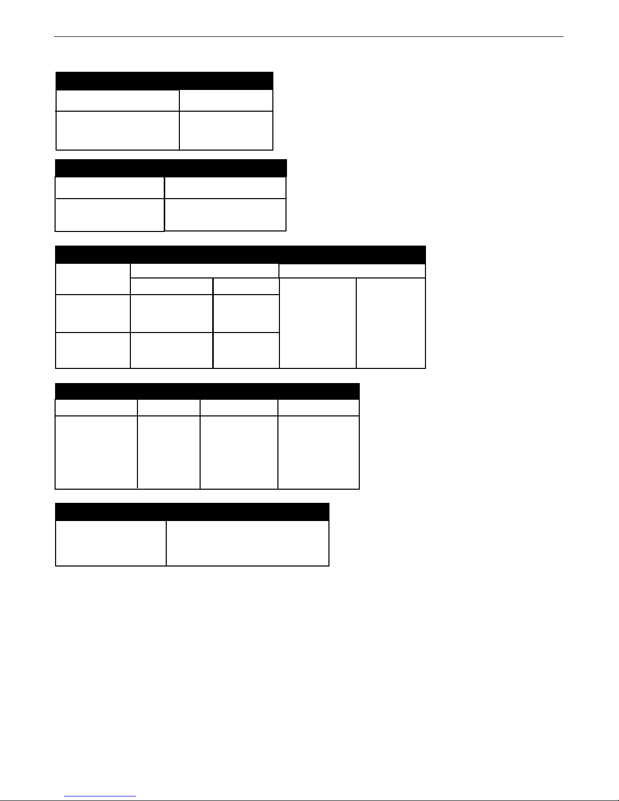
TECHNICAL SPECIFICATIONS –
INPUT VOLTAGE and CURRENT
NPUT AMPERES
NPUT VOLTAGE ± 10%
I
40 VDC
I
RATED OUTPUT @ 104°F (40°C)
DUTY CYCLE
60% rating
INPUT AMPERES
GEARING - WIRE FEED SPEED RANGE-WIRE SIZE
GMAW
GEARING
Normal Speed
(factory setting)
Extra torque
WFS RANGE
50 – 800 ipm
(2.5 – 20.3m/min)
30 – 400 ipm
(1.3 – 10.4m/min)
POWER FEED®25M K2536-4, -5, 25M ALUMINUM K4191-1
4A
500
FCAW
WIRE SIZES
.023 – 1/16"
(0.6 – 1.6mm)
.023 – 1/16"
(0.6 – 1.6mm)
WFS RANGE
50 – 800 ipm
(2.5 – 20.3m/min)
30 – 400 ipm
(1.3 – 10.4m/min)
WIRE SIZES
.030 – 5/64"
(0.8 – 2.0mm)
.030 – 3/32"
(0.8 – 2.4mm)
PHYSICAL DIMENSIONS
HEIGHT WIDTH DEPTH WEIGHT
14.5 Inches 8.5 Inches 23.5 Inches 35 lbs
(368 mm) ( 216 mm) (597 mm) (15.9 kg)
Handle folded down
TEMPERATURE RANGE
OPERATION: -40°F to 122°F (-40°C to 50°C)
STORAGE: -40°F to 185°F (-40°C to 85°C)
IP23
A-1

POWER FEED®25M & 25M ALUMINUM
INSTALLATION
SAFETY PRECAUTIONS
WARNING
ELECTRIC SHOCK CAN KILL.
• Turn the input power OFF at the welding
power source before installation or
changing drive rolls and/or guides.
• Do not touch electrically live parts.
• When inching with the gun trigger,
electrode and drive mechanism are "hot"
to work and ground and could remain
energized several seconds after the gun
trigger is released.
• Welding power source must be connected to system
ground per the National Electrical Code or any applicable
local codes.
• Only qualified personnel should perform maintenance
work.
--------------------------------------------------------------------
LOCATION
For best wire feeding performance, place the POWER FEED®25M
on a stable and dry surface. Keep the wire feeder in a vertical
position. Do not operate the wire feeder on an angled surface of
more than 15 degrees.
HIGH FREQUENCY PROTECTION
CAUTION
Locate the POWER FEED®25M away from radio controlled
machinery. The normal operation of the POWER FEED®25M
ma y adversely affect the opera tion of RF co ntrolled
quipment, which may result in bodily injury or damage to the
e
equipment.
--------------------------------------------------------------------
Do not submerge the POWER FEED®25M.
The POWER FEED®25M is rated IP23 and is suitable for outdoor
use.
The handle of the POWER FEED®25M is intended for moving the
wire feeder about the work place only.
When suspending a wire feeder, insulate the hanging device from
the wire feeder enclosure.
A-2
POWER FEED®25M & 25M ALUMINUM
AA
CC
BB
DD
EE
A
A
BB
CC
D
D
EE
POWER SOURCE
WIRE FEEDER
A
B
H
G
F
E
D
C
K
J
M
L
AA
BB
CC
DD
EE
INSTALLATION
ARCLINK CONTROL CABLES
(See Figure A.3)
ArcLink Control Cables are available in two forms:
K1543-xx series for most indoor or factory installations.
•
• K2683-xx series for outdoor use or when the equipment is
requently moved.
f
ArcLink/LincNet control cables are special high quality cables for
digital communication. The cables are copper 5 conductor cable
in a SO-type rubber jacket. There is one 20 gauge twisted pair
for network communications. This pair has an impedance of
approximately 120 ohms and a propagation delay per foot of less
than 2.1 nanoseconds. There are two 12 gauge conductors that
are used to supply 40VDC to the network. The fifth wire is 18
gauge and is used as an electrode sense lead.
Use of non-standard cables may lead to system shutdowns, poor
arc starting and wire feeding problems.
The control cables connect the power source to the wire feeder,
and the wire feeder to other wire feeders.
Control cables may be connected end to end to extend their
length. Use a maximum of 200 ft. (61.0m) of control cable
between components.
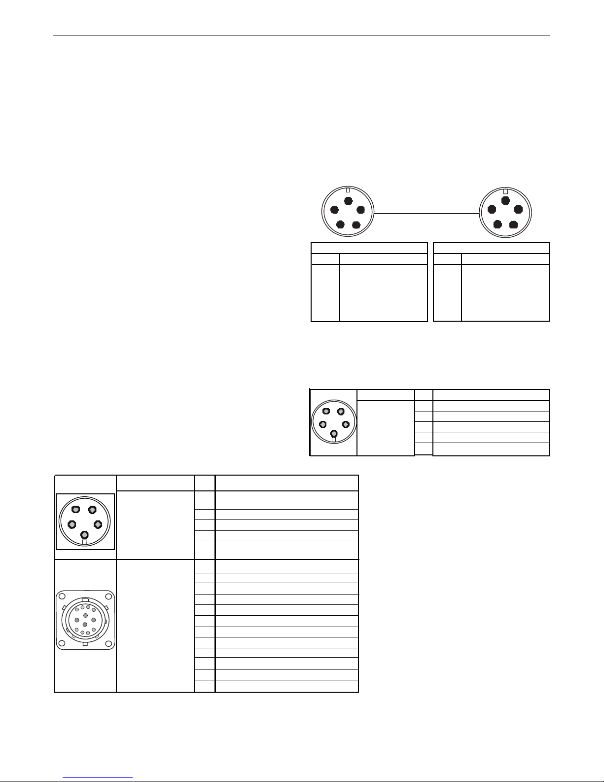
Figure A.3
Power Source
Pin Function
A ArcLink
B ArcLink
C "67" voltage sense
D 40 VDC
E Common
Pin Function
A ArcLink
B ArcLink
C "67" voltage sense
D 40 VDC
E Common
Wire Feeder
CABLE CONNECTIONS
There are two circular connectors on the front of the POWER
FEED®25M.
(See 5-pin and 12-pin Figure A.1)
FIGURE A.1
Function
CC
DD
BB
5-pin trigger
connector for push-
AA
EE
only guns.
12-pin connector for
remote control,
foot/hand amptrol,
push-pull guns and
ArcLink peripherals
PIN
A
B
C
D
E
A
B
C
D
E
F
G
H
J
K
L
M
Dual Procedure Selection
75 Remote potentiometer, common
76 Remote potentiometer, wiper
77 Remote potentiometer, 5K
ArcLink Peripheral Sense
40VDC Common
Pull Motor –
Pull Motor +
Wiring
Trigger
Not used
Common
Common
CANL
CANH
Trigger
Trigger
40VDC +
There is one circular connector on the rear of the POWER FEED
25M. Maximum control cable length is 200 ft (61 m). (See
Figure A.2)
FIGURE A.2
Function
5-pin ArcLink
connector.
PIN
A
B
C
67 Electrode Voltage Sense
D
E
Wiring
ArcLink
ArcLink
40VDC
Common
®
A-3
POWER FEED®25M & 25M ALUMINUM
WELD CABLE SIZE
able A.1 located below are copper cable sizes recommended for different
T
currents and duty cycles. Lengths stipulated are the distance from the welder to
work and back to the welder again. Cable sizes are increased for greater lengths
primarily for the purpose of minimizing cable drop.
COAXIAL WELD CABLE
(See Table A.2)
Coaxial welding cables are specially designed welding cables for pulse welding
or STT®welding. Coaxial weld cables feature low inductance, allowing fast
changes in the weld current. Regular cables have a higher inductance which may
distort the pulse or STT®wave shape. Inductance becomes more severe as the
weld cables become longer.
Coaxial cables work best for high performance waveforms and when:
• long cables are present.
• the cables are housed in a metal tray.
A coaxial weld cable is constructed with multiple small leads wrapped around
one large lead. The large inner lead connects to the electrode stud on the power
source and the electrode connection on the wire feeder. The small leads combine
together to form the work lead, one end attached to the power source and the
other end to the work piece. See Figure A.5
INSTALLATION
o install:
T
1. Turn the input power off at the welding power source.
2. Connect one end of the center lead to the power source electrode
connection, and the other end to the wire feeder electrode
onnection.
c
3. Connect the outer lead bundle to the power source work connection,
and the other end to the work piece. Minimize the length of any
work lead extension for best results.
. Insulate all connections.
4
FIGURE A.5
TABLE A.2
RECOMMENDED CABLE SIZES (RUBBER COVERED COPPER - RATED 75°C)**
COAXIAL CABLE LENGTH
AMPERES
250
300
350
DUTY
CYCLE
100%
60%
60%
0 to 25Ft.
(0 to 7.6M)
1
1
1/0
25 to 50Ft.
(7.6 to 15.2M)
1
1
1/0
50 to 75 Ft.
(15.2 to 22.9M)
1
1
--
75 to 100 Ft.
(22.9 to 30.5M)
1
1/0
--
TABLE A.1
RECOMMENDED CABLE SIZES (RUBBER COVERED COPPER - RATED 167°F or 75°C)**
CABLE SIZES FOR COMBINED LENGTHS OF ELECTRODE AND WORK CABLES
AMPERES
200
200
225
225
250
250
250
250
300
325
350
400
400
500
** Tabled values are for operation at ambient temperatures of 104°F(40°C) and below. Applications above 104°F(40°C) may require cables larger than recommended, or
cables rated higher than 167°F(75°C).
PERCENT
DUTY
CYCLE
60
100
20
40 & 30
30
40
60
100
60
100
60
60
100
60
0 to 50Ft.
(0 to 15M)
2
2
4 or 5
3
3
2
1
1
1
2/0
1/0
2/0
3/0
2/0
50 to 100Ft.
(15 to 30M)
2
2
3
3
3
2
1
1
1
2/0
1/0
2/0
3/0
2/0
100 to 150 Ft.
(30 to 46M)
2
2
2
2
2
1
1
1
1
2/0
2/0
2/0
3/0
3/0
150 to 200 Ft.
(46 to 61M)
1
1
1
1
1
1
1
1
1/0
2/0
2/0
3/0
3/0
3/0
200 to 250 Ft.
(61 to 76M)
1/0
1/0
1/0
1/0
1/0
1/0
1/0
1/0
2/0
3/0
3/0
4/0
4/0
4/0
A-4
POWER FEED®25M & 25M ALUMINUM
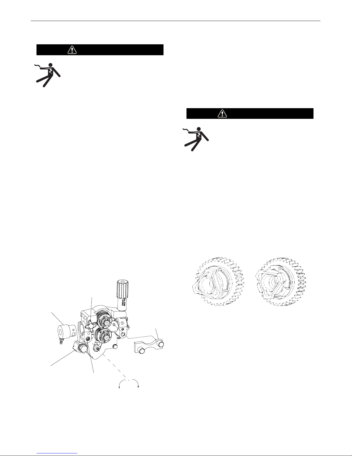
Extra Torque
Gearing
Normal Speed
Gearing
Extra
T
orque
Gearing
Normal
Speed
G
earing
4
00
800
WFS
Feed Force
INSTALLATION
SHIELDING GAS CONNECTION
WARNING
YLINDER may explode if
C
damaged.
CHANGING THE DRIVE MOTOR GEAR RATIO
WARNING
• Turn off input power at the welding
power source before installation or
changing drive roll and/or wire guides.
•Keep cylinder upright and
chained to support.
Do not touch electrically live parts such
•
as the wire drive or internal wiring.
• When feeding with the gun trigger, the
• Keep cylinder away from areas where it may be damaged.
• Never lift welder with cylinder attached.
• Never allow welding electrode to touch cylinder.
• Keep cylinder away from welding or other live electrical
circuits.
• BUILD UP OF SHIELDING GAS MAY HARM HEALTH OR KILL.
• Only qualified personnel should perform this operation.
--------------------------------------------------------------------
electrode and wire drive mechanism are
"hot" to work and ground and could
remain energized several seconds after
the gun trigger is released.
• Shut off shielding gas supply when not in use.
• See American National Standard Z-49.1, "Safety
in Welding and Cutting” Published by the
American Welding Society.
--------------------------------------------------------------------
MAXIMUM INLET PRESSURE IS 100 PSI. (6.9 BAR.)
Install the shielding gas supply as follows:
1. Secure the cylinder to prevent it from falling.
2. Remove the cylinder cap. Inspect the cylinder valves and
regulator for damaged threads, dirt, dust, oil or grease. Remove
dust and dirt with a clean cloth. DO NOT ATTACH THE
REGULATOR IF OIL, GREASE OR DAMAGE IS PRESENT! Inform
your gas supplier of this condition. Oil or grease in the presence
of high pressure oxygen is explosive.
3. Stand to one side away from the outlet and open the cylinder
valve for an instant. This blows away any dust or dirt which may
have accumulated in the valve outlet.
4. Attach the flow regulator to the cylinder valve and tighten the
union nut(s) securely with a wrench. Note: if connecting to 100%
CO2cylinder, insert regulator adapter between regulator and
cylinder valve. If adapter is equipped with a plastic washer, be
sure it is seated for connection to the CO2cylinder.
5. Attach one end of the inlet hose to the outlet fitting of the flow
regulator. Attach the other end to the welding system shielding
gas inlet. Tighten the union nuts with a wrench.
6. Before opening the cylinder valve, turn the regulator adjusting
knob counterclockwise until the adjusting spring pressure is
released.
7. Standing to one side, open the cylinder valve slowly a fraction of
a turn. When the cylinder pressure gage stops moving, open the
valve fully.
8. The flow regulator is adjustable. Adjust it to the flow rate
recommended for the procedure and process being used before
making a weld.
Tools required:
• 1/4" hex key wrench
• 3/4" open end wrench
• 9/16" socket and ratchet wrench
• 7/16" nut driver
• 5/16" nut driver
• Phillips screw driver
1. Turn power off at the welding power source.
. Remove the spool of electrode from the wire feeder.
2
3. Loosen the thumb screw at the wire drive and remove the welding
gun.
4. Remove the outer wire guide, drive rolls and inner wire guide.
5. Use a 7/16" nut driver to remove the gear cover.
6. Use 9/16" socket and ratchet wrench to remove the lower drive roll
hub retainer. Remove the lower drive roll hub.
7. With a Phillips screwdriver, remove the screw, washer and collar
holding the pinion gear. Remove the pinion gear.
A-5

POWER FEED®25M & 25M ALUMINUM
8. Remove the busbar by unscrewing the bolt using a 3/4" open end
wrench.
. With a 1/4" hex key wrench, loosen the socket head cap screw
9
securing the gun bushing. Remove the gun bushing from the wire
drive.
10. With a 5/16" nut driver remove the five screws securing the wire
drive panel. Lift out the wire drive panel and disconnect the molex
connections.
11. Using a 5/16" nut driver, remove the four screws securing the
cover.
12. With a Phillips screwdriver, remove the three screws and lock
washers securing the motor. Remove the motor.
13. Place the motor in the new position.
14. Assemble the three screws and lock washer holding the wire drive
motor.
INSTALLATION
15. Assemble the molex connections and place the wire drive assembly
inside the wire feeder. Route the gas hose through the opening in
the wire drive panel.
16. Place the gun bushing in the wire drive and align the threaded hole
in the gun bushing with the hole in the feed plate. With a 1/4" hex
key, tighten the socket head cap screw to secure the bushing in the
wire drive.
17. Reassemble the busbar and tighten the mounting hardware with a
3/4" open end wrench.
18. Place the new gear on the motor shaft. Secure the gear to the
motor shaft with the collar, washer and screw.
19. Reassemble the lower drive roll hub and lower drive roll hub
retainer.
20. Reassemble the gear cover.
21. Reassemble the inner wire guide, drive rolls and outer wire guide.
22. Place the welding gun into the gun bushing and secure with the
thumb screw.
23. Restore power. Set the appropriate gear ratio using the set-up
menu.
A-6
POWER FEED®25M & 25M ALUMINUM
GUN RECEIVER BUSHING
LOOSEN TIGHTEN
THUMB SCREW
OUTER WIRE GUIDE
SOCKET HEAD
CAP SCREW
CONNECTOR BLOCK
UNLOCKED
POSITION
LOCKED
POSITION
INSTALLATION
WIRE DRIVE CONFIGURATION
See Figure A-6)
(
Changing the Gun Receiver Bushing
WARNING
ELECTRIC SHOCK can kill.
• Turn the input power OFF at the welding
power source before installation or
changing drive rolls and/or guides.
• Do not touch electrically live parts.
• When inching with the gun trigger, electrode and drive
mechanism are "hot" to work and ground and could
remain energized several seconds after the gun trigger is
released.
• Only qualified personnel should perform maintenance
work.
-------------------------------------------------------------------Tools required:
• 1/4" hex key wrench.
Note: Some gun bushings do not require the use of the thumb
screw.
1. Turn power off at the welding power source.
2. Remove the welding wire from the wire drive.
3. Remove the thumb screw from the wire drive.
4. Remove the welding gun from the wire drive.
5. Loosen the socket head cap screw that holds the connector
bar against the gun bushing.
Important: Do not attempt to completely remove the
socket head cap screw.
6. Remove the outer wire guide, and push the gun bushing out
of the wire drive. Because of the precision fit, light tapping
may be required to remove the gun bushing.
7. Disconnect the shielding gas hose from the gun bushing, if
required.
. Connect the shielding gas hose to the new gun bushing, if
8
required.
9. Rotate the gun bushing until the thumb screw hole aligns
with the thumb screw hole in the feed plate. Slide the gun
receiver bushing into the wire drive and verify the thumb
screw holes are aligned.
0. Tighten the socket head cap screw.
1
11. Insert the welding gun into the gun bushing and tighten the
thumb screw.
PROCEDURE TO INSTALL DRIVE ROLLS AND WIRE
GUIDES
WARNING
ELECTRIC SHOCK can kill.
• Turn the input power OFF at the welding
power source before installation or
changing drive rolls and/or guides.
• Do not touch electrically live parts.
• When inching with the gun trigger, electrode and drive
mechanism are "hot" to work and ground and could
remain energized several seconds after the gun trigger is
released.
• Only qualified personnel should perform maintenance
work.
--------------------------------------------------------------------
1. Turn power off at the welding power source.
2. Release the idle roll pressure arm.
3. Remove the outer wire guide by turning the knurled
thumbscrews counter-clockwise to unscrew them from the
feed plate.
4. Rotate the triangular lock and remove the drive rolls.
5. Remove the inner wire guide.
FIGURE A-6
6. Insert the new inner wire guide, groove side out, over the two
locating pins in the feed plate.
7. Install a drive roll on each hub assembly secure with the
triangular lock.
8. Install the outer wire guide by aligning it with the pins and
tightening the knurled thumbscrews.
9. Close the idle arm and engage the idle roll pressure arm.
Adjust the pressure appropriately
A-7
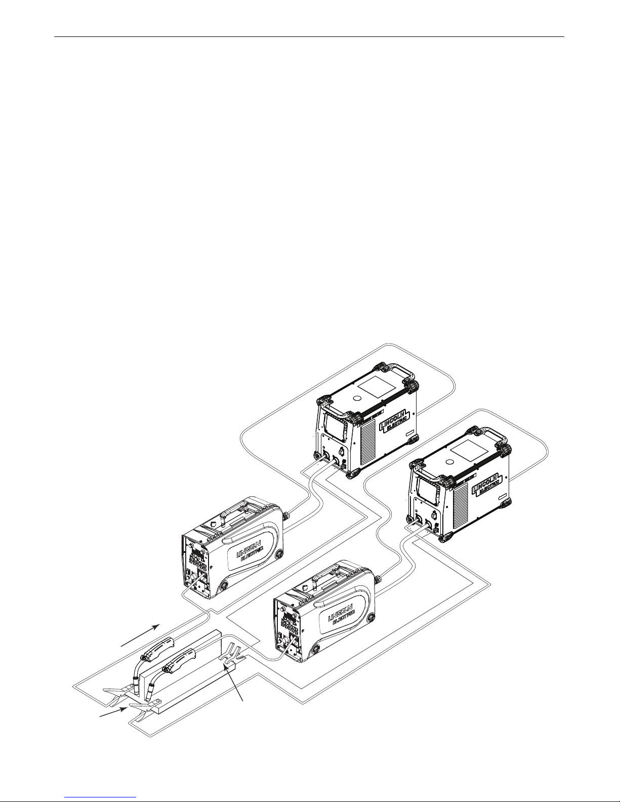
Direction
of Travel
Connect all
Work Leads at
the Beginning
of the Weld
Connect all Sense
Leads at the End
of the Weld
POWER FEED®25M & 25M ALUMINUM
REMOTE SENSE LEAD SPECIFICATIONS
Welding with Multiple Arcs:
See Figure A.7)
(
pecial care must be taken when more than one arc is welding
S
simultaneously on a single part. Arc blow and arc interference
may occur or be magnified. Each power source requires a work
lead from the work stud to the welding fixture. Do not combine
all of the work leads into one lead. Performing welding in the
direction away from the work leads. Connect all of the work
sense leads from each power source to the work piece at the
end of the weld, such that they are out of the path of the weld
current. See Figure A.7
For the best results when pulse welding, set the wire size and
wire feed speed the same for all the arcs. When these
parameters are identical, the pulsing frequency will be the same,
helping to stabilize the arcs.
FIGURE A.7
INSTALLATION
A-8

POWER FEED®25M & 25M ALUMINUM
INSTALLATION
LOADING SPOOLS OF WIRE
WARNING
• Keep hands, hair, clothing and tools away from
otating equipment.
r
• Do not wear gloves when threading wire or
changing wire spool.
• Only qualified personnel should install, use or
service this equipment.
-------------------------------------------------------------------Loading 10 to 15 lb. (4.5 – 6.8kg) Spools.
A K468 spindle adapter is required for loading 2" (51mm) wide
spools on 2" (51mm) spindles. Use a K468 spindle adapter for
loading 2-1/2" (64mm) wide spools.
1. Squeeze the release bar on the retaining collar and remove it
from the spindle.
2. Place the spindle adapter on the spindle, aligning the spindle
brake pin with the hole in the adapter.
3. Place the spool on the spindle and align the adapter brake tab
with one of the holes in the back side of the spool. An
indicator mark on the end of the spindle shows the orientation
of the brake tab. Be certain the wire feeds off of the spool in
the proper direction.
4. Re-install the retaining collar. Make sure that the release bar
snaps out and that the retaining collar fully engages the
groove on the spindle.
TYPICAL SYSTEM CONFIGURATIONS
Standard Features
Arc Performance
• Push-Pull ready for welding aluminum with Pulse and Pulseon-Pulse®waveforms.
• STT®capable when used with STT®equipped Power Waves.
• Waveform Control Technology®for welds with good
appearance and low spatter, even when welding nickel alloys.
Wire Drive
Patented 2 roll drive system. MAXTRAC®technology delivers
great feeding because:
• Patent pending drive rolls improve traction on solid wire by up
to 20%.
• The precision machined, rigid aluminum alloy frame results in
maximum drive roll clamping pressure.
• Patented split wire guides fully support the wire and virtually
eliminate birdnesting.
• No tools required to change the drive rolls and wire guides.
• Patented dual spring pressure arms have sensitivity for
feeding soft wires without crushing them, and have plenty of
compression force for feeding solid or stiff wires.
• All gear driven rolls for more feeding force.
• Changeable gun bushings easily accept guns from other
manufacturers.
• Brass-to-brass connections between the electrode connection
and the gun minimize voltage drop variations, resulting in
consistent arc performance all day, every day.
• Powerful, quiet motor with integrated tachometer for accurate
WFS regulation.
Extras:
• Flowmeter with gas control valve
• Push-Pull ready.
• Remote control / Foot amptrol ready.
• Internal heater for keeping condensation off of the spool of wire.
• Internal lights for illuminating the wire drive compartment.
Options
• Water cooling kit for use with water cooled guns.
A-9

POWER FEED®25M & 25M ALUMINUM
SAFETY PRECAUTIONS
READ AND UNDERSTAND ENTIRE SECTION BEFORE OPERATING
MACHINE.
• Turn the input power OFF at the welding power source
before installation or changing drive rolls and/or guides.
• Do not touch electrically live parts.
• When inching with the gun trigger, electrode and drive
mechanism are "hot" to work and ground and could
remain energized several seconds after the gun trigger
is released.
• Do not operate with covers, panels or guards removed
or open.
• Only qualified personnel should perform maintenance
work.
------------------------------------------------------------------
------------------------------------------------------------------
WARNING
• ELECTRIC SHOCK CAN KILL. Unless
using COLD FEED featu re , wh en
eeding with gun trigger, the electrode
f
and drive mechanis m are alway s
electrica lly ener gi zed and c ould
remain energized several seconds
after the welding ceases.
• FUMES AND GA SSES c an b e
dangerous.
• Keep your head out of fumes.
• Use ventilation or exhaust to remove
fumes from breathing zone.
• WELDING SPARKS can cause fire or
explosion.
• Keep flammable material away.
OPERATION
------------------------------------------------------------------
ARC RAYS can burn.
• Wear eye, ear and body protection.
------------------------------------------------------------------
SEE ADDITIONA L WA RNING
IN FO RM ATION U ND ER ARC WELDING
SAFETY P RE CAUTION S A ND IN T HE
FRONT OF THIS OPERATING MANUAL.
------------------------------------------------------------------
DUTY CYCLE
The POWER FEED®25M is rated for 500 amps, 60% duty
cycle. The duty cycle is based on a 10 minute cycle.
For example, when welding at 500 amps, the POWER FEED
25M may run continuously for 6 minutes and then must sit idle
for 4 minutes.
®
B-1
POWER FEED®25M & 25M ALUMINUM
CASE FRONT CONTROLS
SEE FIGURE B.1)
(
1. Left DISPLAY window
Shows WIRE FEED SPEED or AMPERAGE.
2. Left KNOB
Adjusts values in left display.
3. Status LED
Illuminates a steady green when communicating to the power
source properly.
4. Main display
Shows detailed welding and diagnostic information.
OPERATION
16. Set-Up
Lights when feeder is set-up.
17. Right Button
Changes the Main display to show Start Options or End
Options.
18. Set Knob
Changes the value on the Main display.
19. Memories Buttons
For selection of common procedures.
5. Left Button
Changes the Main display to show the Weld Mode or UltimArc.
6. Procedure Button
Selects A or B procedure, or gun control.
7. 2-Step/4-Step Button
Toggles between 2-step and 4-step trigger operation.
8. 5-pin connector
Trigger connector for a push-only gun.
9. ON/OFF switch
Controls power to the POWER FEED
10. 3 Amp Circuit Breaker
Protects the 12-pin accessories
11. 12-pin connector
Connection for push-pull guns, remotes
12. Cover
Covers location for optional water cooling line.
13. Right Display window
Shows VOLTAGE or TRIM.
®
25M.
10
11
12
FIGURE B.1
1
2
3
4
5
6
7
13
14
15
16
17
18
19
8
9
14. Right Knob
Adjusts values in the right display.
15. Thermal
Lights when the drive overheats.
B-2
POWER FEED®25M & 25M ALUMINUM
9. ON-OFF SWITCH
The On-Off Switch turns the wire feeder power on and off. It
does not control the power to the welding power source.
ELECTRIC SHOCK can kill.
• Welding power source must be connected to system
ground per the National Electrical Code or any applicable
local codes.
• Only qualified personnel should perform maintenance
work.
--------------------------------------------------------------------
OPERATION
WARNING
• Turn the input power OFF at the welding
power source before installation or
changing drive rolls and/or guides.
• Do not touch electrically live parts.
• When inching with the gun trigger,
electrode and drive mechanism are
"hot" to work and ground and could
remain energized several seconds after
the gun trigger is released.
LED condition
Steady green
Blinking green.
Blinking green, fast
Blinking green
followed by blinking
red.
STATUS LED
US
(See Table B.1)
STAT
The status LED indicates system status. Normal operation is a
steady green light.
Note: During normal power-up, the LED may flash red and/or
green as the equipment performs self tests.
TABLE B.1
Definition
System okay. The power source and wire feeder are communicating normally.
Occurs during a reset and indicates the power source is identifying each component in the system. This is normal for up to 15
seconds after power-up, or if the system configuration is changed during operation.
Indicates that one or more pieces of ArcLink equipment are not mapping properly.
Non-recoverable system fault. If the power source or wire feeder status LED is flashing any combination of red and green, errors
are present in the system. Read the error code before the machine is turned off.
Instructions for reading the error code are detailed in the Service Manual. Individual code digits are flashed in red with a long
pause between digits. If more than one code is present, the codes will be separated by a green light.
To clear the error, turn the power source OFF, and then back ON to reset. See Troubleshooting Section E.
B-3
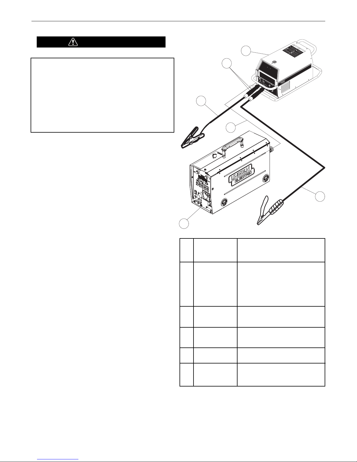
POWER FEED®25M & 25M ALUMINUM
W
A
R
N
I
N
G
W
A
R
N
I
N
G
A
V
I
S
O
D
E
P
R
E
C
A
U
C
I
O
N
A
T
T
E
N
T
I
O
N
!
!
!
!
L
o
r
e
m
i
p
s
u
m
d
o
l
o
r
s
i
t
a
m
e
t
c
o
n
s
e
c
t
e
t
u
e
r
a
d
i
p
i
s
c
i
n
g
Lorem ipsum dolor sit amet consectetuer adipiscing
e
l
i
t
,
e
d
d
i
a
m
n
o
n
u
m
m
y
n
i
b
h
e
u
i
s
m
o
d
t
i
n
c
i
d
u
n
t
u
t
elit, ed diam nonummy nibh euismod tincidunt ut
l
a
o
r
e
e
t
d
o
l
o
r
e
m
a
g
n
a
a
l
i
q
u
a
m
e
r
a
t
laoreet dolore magna aliquam erat
L
o
re
m
i
p
s
u
m
d
o
l
o
r
s
i
t
a
m
e
t
c
o
n
s
e
c
t
e
t
u
e
r
a
d
i
p
i
s
c
i
n
g
Lorem ipsum dolor sit amet consectetuer adipiscing
e
l
i
t
,
e
d
d
i
a
m
n
o
n
u
m
m
y
n
i
b
h
e
u
i
s
m
o
d
t
i
n
c
i
d
u
n
t
u
t
elit, ed diam nonummy nibh euismod tincidunt ut
l
a
o
r
e
e
t
d
o
l
o
r
e
m
a
g
n
a
a
l
i
q
u
a
m
e
ra
t
laoreet dolore magna aliquam erat
L
o
r
e
m
i
p
s
u
m
d
o
l
o
r
s
i
t
a
m
e
t
c
o
n
s
e
c
t
e
t
u
e
r
a
d
i
p
i
s
c
i
n
g
Lorem ipsum dolor sit amet consectetuer adipiscing
e
l
i
t
,
e
d
d
i
a
m
n
o
n
u
m
m
y
n
i
b
h
e
u
i
s
m
o
d
t
i
n
c
i
d
u
n
t
u
t
elit, ed diam nonummy nibh euismod tincidunt ut
l
a
o
r
e
e
t
d
o
l
o
r
e
m
a
g
n
a
a
l
i
q
u
a
m
e
r
a
t
laoreet dolore magna aliquam erat
W
A
R
N
I
N
G
R
E
M
O
T
E
P
O
W
E
R
O
F
F
O
N
P
O
W
E
R
W
A
V
E
3
5
5
1
6
4
3
2
5
OPERATION
POWER WAVE SYSTEM OPERATION
WARNING
The serviceability of a product or structure utilizing the welding
rograms is and must be the sole responsibility of the
p
builder/user. Many variables beyond the control of The Lincoln
lectric Company affect the results obtained in applying these
E
programs. These variables include, but are not limited to,
welding procedure, plate chemistry and temperature, weldment
design, fabrication methods and service requirements. The
available range of a welding program may not be suitable for
all applications, and the build/user is and must be solely
responsible for welding program selection.
-------------------------------------------------------------------The steps for operating the Power Wave will vary depending
upon the user interface of the welding system. The flexibility of
the Power Wave lets the user customize operation for the best
performance.
First, consider the desired welding process and the part to be
welded. Choose an electrode material, diameter, shielding gas
and process (GMAW, GMAW-P, GMAW-STT®, etc.)
IGURE B.2
F
Second, find the program in the welding software that best
matches the desired welding process. The standard software
shipped with the Power Waves encompasses a wide range of
common processes and will meet most needs. If a special
welding program is desired, contact the local Lincoln Electric
sales representative.
All adjustments are made on the user interface. Because of the
different configuration options your system may not have all of
the following adjustments. Regardless of availability, all controls
are described below.
SMAW (STICK) WELDING
SMAW is most often used for outdoor construction, pipe welding
and general repairs. The wire feeder controls Amperage, Output
Control and Arc Force during SMAW welding.
During SMAW welding, the user interface sets the weld
parameters and the wire drive remains idle.
The “Volts”-”Trim” control is used to turn the power Source
Output ON or OFF. (See Figure B.3)
SMAW Welding (See Figure B.2)
K2202-1 Power Wave®455M
1 K2203-1 Power Wave®455M/STT
K2823-xx Power Wave®S350
K2230-1 POWER FEED®10M, Bench
Model
2 K2234-1
POWER FEED®10M Dual,
Bench Model
K2536-4, -5 POWER FEED®25M
3 K2683-xx Heavy Duty ArcLink Cable
K1543-xx ArcLink Control Cable
4 K1842-xx Weld Power Cable, Lug to Lug
K910-xx Ground Clamp
5 K909-xx Electrode Holder
6 K2176-1 Twist-Mate to Lug Cable Adapter
K960-3 Tweco Style Cam Lock Torch
Adapter
B-4
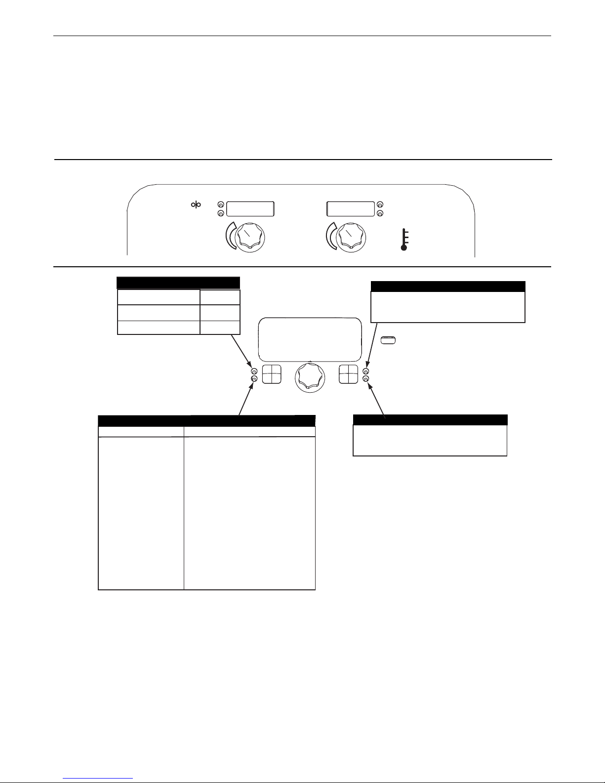
POWER FEED®25M & 25M ALUMINUM
START OPTIONS
E
ND OPTIONS
S
ETUP
EFFECT / RANGE
ARC FORCE
(Soft)-10.0 to
(Crisp)+10.0
DESCRIPTION
No arc ending options are active for
SMAW (Stick) welding modes.
END OPTIONS
UltimArc™ Control
WELD MODE
UltimArc™ Control
PROCESS
Stick Soft(7018)
Stick Crisp(6010)
MODE
1
2
CC STICK MODES
Stick Crisp
2
LESS
AMPS
MORE
AMPS
O
UTPUT
OFF
OUTPUT
ON
+
+
194
0
AMPS
WFS
VOLTS
TRIM
n
No arc starting options are active for
SMAW (Stick) welding modes.
START OPTIONS
Arc Force adjusts the short
circuit current f or a soft arc, or
for a forceful, driving arc. It
helps to prevent sticking and
shorting of organic coated
electrodes, particularity globular
transfer types such as
stain le ss an d low hydrogen.
A rc Force is especially
effective for root pass on pipe
with stainless electrode and
helps to minimize spatter for
certain electrodes and
procedure as with low
hydrogen, etc.
SMAW (STICK) WELDING
SMAW is most often used for outdoor construction, pipe welding
and general repairs. The wire feeder controls Amperage, Output
Control and Arc Force during SMAW welding.
During SMAW welding the wire drive remains idle.
BASIC OPERATION
CONTROL OPTIONS
OPERATION
NOTE: When a remote control pot such as a K936-1 or -2 Hand
Amptrol is connected, and P.17 is setup for Stick/Gouge
Remote, the pot value will be shown on the left display, but can
only be adjusted to the max workpoint. The max workpoint is
set by adjusting the left knob. When the left knob is adjusted,
the left display will show the max workpoint setting, and will
switch back to show the pot setting when the knob is done
being adjusted.
B-5
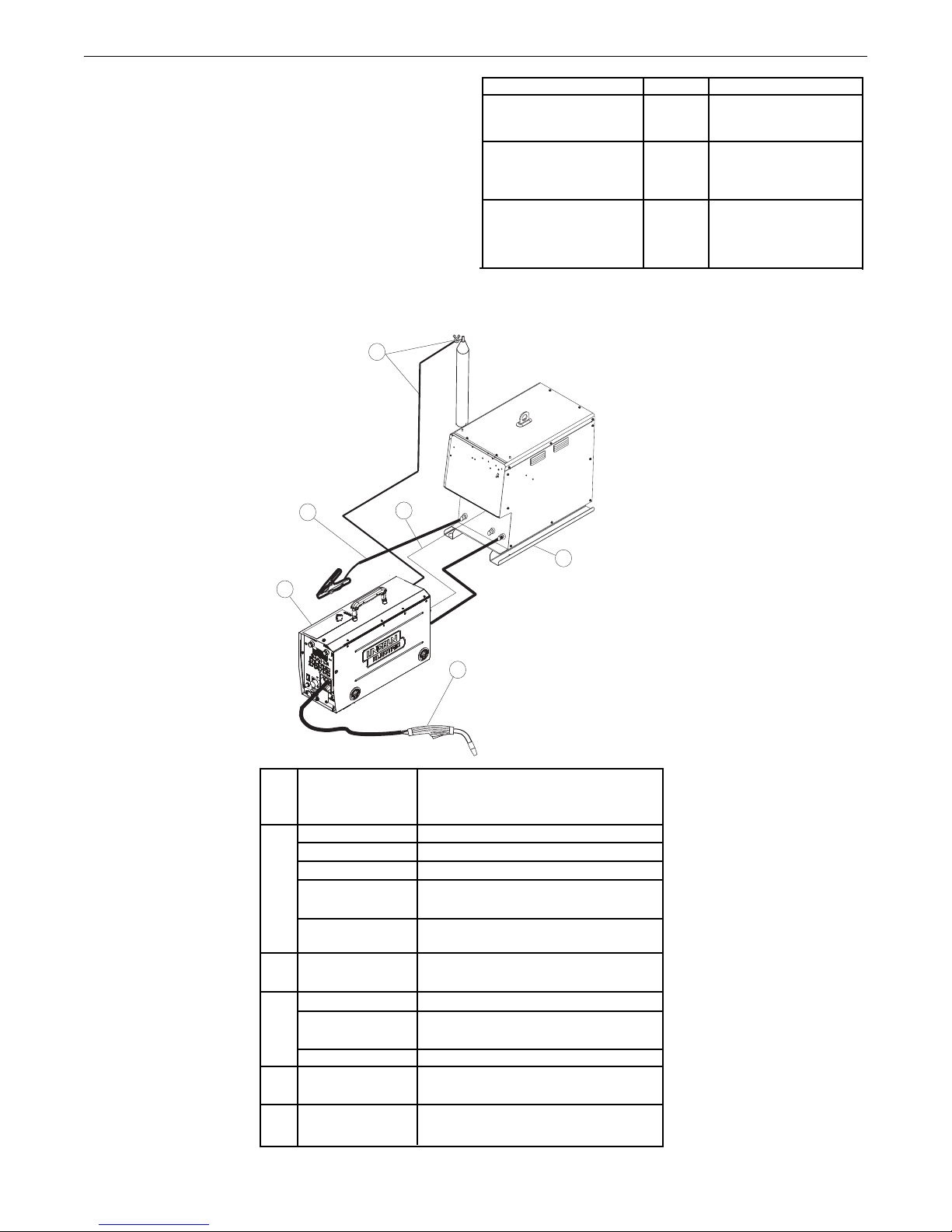
POWER FEED®25M & 25M ALUMINUM
6
4
3
2
5
1
OPERATION
SET-UP, PHYSICAL, NON-SYNERGIC GMAW AND
FCAW WELDING
See Figure B.4)
(
Non-synergic GMAW and FCAW welding mimics the welding
controls of traditional welding power sources. Voltage and WFS
re set as independent variables.
a
FIGURE B.4
Three non-synergic welding modes are available.
Description Mode Used for:
GMAW, Standard CV 5 Best for traditional
MIG welding.
GMAW, Power 40 Specialized GMAW mode.
FCAW 6 Best for self shielded
electrodes like
Innershield®.
K2202-1 Power Wave®455M
1 K2203-1 Power Wave®455M/STT
K2823-xx Power Wave®S350
K2230-1
K2234-1
K2536-4, -5 POWER FEED®25M
2 KP1696-xx, Drive Roll Kit, 2 Roll Feeder
KP1697-xx
KP1505-xx, Drive Roll Kit, 4 Roll Feeder
KP1507-xx
3 K1543-xx Digital Control Cable
K2683-xx
4 K1842-xx Weld Power Cable, Lug to Lug
K960-3 Tweco Style Cam Lock Torch
K910-xx Ground Clamp
5 See Magnum
Literature
6 K586-1 Deluxe Regulator for Mixed
POWER FEED®10M, Bench Model
POWER FEED®10M Dual, Bench Model
Adapter
®
MIG gun
Shielding Gases and Gas Hose
B-6
POWER FEED®25M & 25M ALUMINUM
W
FS
VOLTS
TRIM
300
25.3
WFS
VOLTS
TRIM
250
5.7
EFFECT / RANGE
Crater Procedure
Burnback:
DESCRIPTION
Crater Procedure controls the
WFS and Volts for a specified
ti me at the end o f th e we ld
after the trigger is release d.
Du ring the Cra ter time, the
machine will ramp up or down
from the Weld Procedu re to
the Crater Procedure.
Th e burn ba ck time i s th e
amount of time that the weld
output continues after the wire
stops feeding. It prevents the
wire from sticking in the puddle
and prepa res the end of the
wire for the next arc start.
PROCESS
GMAW, STANDARD CV
GMAW, POWER MODE
FCAW, STANDARD CV
WELD MODE
5
40
6
ULTIMARC*
WELD MODE
END OPTIONS
START OPTIONS
DESCRIPTION
Pinch controls the arc characte-
-ristics when short-arc welding.
*Wave Control in Power Wave
355 and 455 machines.
EFFECT / RANGE
(Soft)-10.0 to
(Crisp)+10.
PINCH
0
EFFECT / RANGE
Preflow Time
Run-In WFS:
.
Start Procedure
DESCRIPTION
A
d j u s t s t h e
time
that
s
hielding
gas
flows
a
fter the trigger is
pulled
and
prior to feeding wire.
R
un -I n s et s t he wire fee d
speed from the time the trigger
i
s pulled until an arc is established or 2.5 seconds.
The Start Procedure controls
t
he WFS and Volts for a specified time at the beg inning of
the weld. During the start time,
the machine will r amp up or
down from the Start Procedure
to the preset We ld in g
Procedure.
Spot Timer
Ad ju st t he time wel di ng w il l
co nt in ue e ven if th e tr ig ge r
is s ti ll p ulled. Th is o pt io n
ha s no e ff ect in 4- St ep
Tr ig ge r Mo de.
START OPTIONS
END OPTIONS
SET
SETUP
5
STD CV MIG
WELD MODE
ARC CONTROL
®
Postflow Time
Adjusts the time that shielding
gas flows after the welding output turns off.
OPERATION
DISPLAY OPTIONS:
Modes 5 and 6:
USER INTERFACE Operation, Non-Synergic GMAW (MIG) and
FCAW (Flux Cored) Welding.
ode 40:
M
B-7
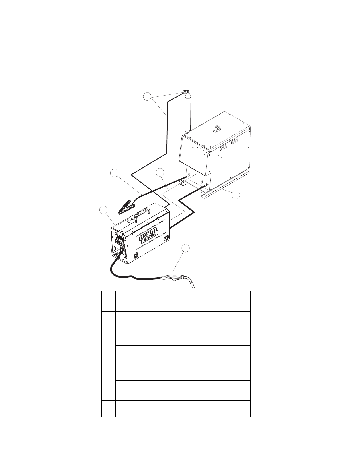
POWER FEED®25M & 25M ALUMINUM
6
4
3
2
5
1
GMAW (MIG) SYNERGIC WELDING
Synergic welding allows for easy procedure setting. The WFS
and Voltage change together to maintain an optimal arc length.
During synergic welding , when the WFS (left) knob is rotated,
he voltage is adjusted accordingly to maintain a similar arc
t
length.
Set-up, Physical
OPERATION
FIGURE B.5
K2202-1 Power Wave 455M
1 K2203-1 Power Wave 455M/STT
K2823-xx Power Wave S350
K2230-1
K2234-1
POWER FEED®10M, Bench Model
POWER FEED®10M Dual, Bench Model
K2536-4, -5 POWER FEED®25M
2 KP1696-xx, Drive Roll Kit, 2 Roll Feeder
KP1697-xx
KP1505-xx, Drive Roll Kit, 4 Roll Feeder
KP1507-xx
3 K1543-xx Digital Control Cable
K2683-xx
4 K1842-xx Weld Power Cable, Lug to Lug
K910-xx Ground Clamp
5 See Magnum
®
MIG gun
Literature
6 K586-1 Deluxe Regulator for Mixed
Shielding Gases and Gas Hose
B-8
 Loading...