

Page 1
POWER FEED 10S
RETURN TO MAIN MENU
IM850-A
April, 2005
For use with machines having Code Numbers:
Safety Depends on You
Lincoln arc welding and cutting
equipment is designed and built
with safety in mind. However, your
overall safety can be increased by
proper installation ... and thoughtful operation on your part. DO
NOT INSTALL, OPERATE OR
REPAIR THIS EQUIPMENT
WITHOUT READING THIS
MANUAL AND THE SAFETY
PRECAUTIONS CONTAINED
THROUGHOUT. And, most
importantly, think before you act
and be careful.
11063, 11064, 11127
Cleveland, Ohio 44117-1199 U.S.A. TEL: 216.481.8100 FAX: 216.486.1751 WEB SITE: www.lincolnelectric.com
OPERATOR’S MANUAL
Copyright © 2005 Lincoln Global Inc.
• World's Leader in Welding and Cutting Products •
• Sales and Service through Subsidiaries and Distributors Worldwide •
Page 2
i
SAFETY
i
WARNING
CALIFORNIA PROPOSITION 65 WARNINGS
Diesel engine exhaust and some of its constituents
are known to the State of California to cause cancer, birth defects, and other reproductive harm.
The Above For Diesel Engines
ARC WELDING CAN BE HAZARDOUS. PROTECT YOURSELF AND OTHERS FROM POSSIBLE SERIOUS INJURY OR DEATH.
KEEP CHILDREN AWAY. PACEMAKER WEARERS SHOULD CONSULT WITH THEIR DOCTOR BEFORE OPERATING.
Read and understand the following safety highlights. For additional safety information, it is strongly recommended that you
purchase a copy of “Safety in Welding & Cutting - ANSI Standard Z49.1” from the American Welding Society, P.O. Box
351040, Miami, Florida 33135 or CSA Standard W117.2-1974. A Free copy of “Arc Welding Safety” booklet E205 is available
from the Lincoln Electric Company, 22801 St. Clair Avenue, Cleveland, Ohio 44117-1199.
BE SURE THAT ALL INSTALLATION, OPERATION, MAINTENANCE AND REPAIR PROCEDURES ARE
PERFORMED ONLY BY QUALIFIED INDIVIDUALS.
The engine exhaust from this product contains
chemicals known to the State of California to cause
cancer, birth defects, or other reproductive harm.
The Above For Gasoline Engines
FOR ENGINE
powered equipment.
1.a. Turn the engine off before troubleshooting and maintenance
work unless the maintenance work requires it to be running.
____________________________________________________
1.b. Operate engines in open, well-ventilated
areas or vent the engine exhaust fumes
outdoors.
____________________________________________________
1.c. Do not add the fuel near an open flame
welding arc or when the engine is running.
Stop the engine and allow it to cool before
refueling to prevent spilled fuel from vaporizing on contact with hot engine parts and
igniting. Do not spill fuel when filling tank. If
fuel is spilled, wipe it up and do not start
engine until fumes have been eliminated.
____________________________________________________
1.d. Keep all equipment safety guards, covers and devices in
position and in good repair.Keep hands, hair, clothing and
tools away from V-belts, gears, fans and all other moving
parts when starting, operating or repairing equipment.
____________________________________________________
1.e. In some cases it may be necessary to remove safety
guards to perform required maintenance. Remove
guards only when necessary and replace them when the
maintenance requiring their removal is complete.
Always use the greatest care when working near moving
parts.
___________________________________________________
1.f. Do not put your hands near the engine fan.
Do not attempt to override the governor or
idler by pushing on the throttle control rods
while the engine is running.
1.h. To avoid scalding, do not remove the
radiator pressure cap when the engine is
hot.
ELECTRIC AND
MAGNETIC FIELDS
may be dangerous
2.a. Electric current flowing through any conductor causes
localized Electric and Magnetic Fields (EMF). Welding
current creates EMF fields around welding cables and
welding machines
2.b. EMF fields may interfere with some pacemakers, and
welders having a pacemaker should consult their physician
before welding.
2.c. Exposure to EMF fields in welding may have other health
effects which are now not known.
2.d. All welders should use the following procedures in order to
minimize exposure to EMF fields from the welding circuit:
2.d.1.
Route the electrode and work cables together - Secure
them with tape when possible.
2.d.2. Never coil the electrode lead around your body.
2.d.3. Do not place your body between the electrode and
work cables. If the electrode cable is on your right
side, the work cable should also be on your right side.
___________________________________________________
1.g. To prevent accidentally starting gasoline engines while
turning the engine or welding generator during maintenance
work, disconnect the spark plug wires, distributor cap or
magneto wire as appropriate.
2.d.4. Connect the work cable to the workpiece as close as
possible to the area being welded.
2.d.5. Do not work next to welding power source.
Mar ‘95
Page 3
ii
SAFETY
ii
ELECTRIC SHOCK can
kill.
3.a. The electrode and work (or ground) circuits
are electrically “hot” when the welder is on.
Do not touch these “hot” parts with your bare
skin or wet clothing. Wear dry, hole-free
gloves to insulate hands.
3.b. Insulate yourself from work and ground using dry insulation.
Make certain the insulation is large enough to cover your full
area of physical contact with work and ground.
In addition to the normal safety precautions, if welding
must be performed under electrically hazardous
conditions (in damp locations or while wearing wet
clothing; on metal structures such as floors, gratings or
scaffolds; when in cramped positions such as sitting,
kneeling or lying, if there is a high risk of unavoidable or
accidental contact with the workpiece or ground) use
the following equipment:
• Semiautomatic DC Constant Voltage (Wire) Welder.
• DC Manual (Stick) Welder.
• AC Welder with Reduced Voltage Control.
3.c. In semiautomatic or automatic wire welding, the electrode,
electrode reel, welding head, nozzle or semiautomatic
welding gun are also electrically “hot”.
3.d. Always be sure the work cable makes a good electrical
connection with the metal being welded. The connection
should be as close as possible to the area being welded.
3.e. Ground the work or metal to be welded to a good electrical
(earth) ground.
ARC RAYS can burn.
4.a. Use a shield with the proper filter and cover
plates to protect your eyes from sparks and
the rays of the arc when welding or observing
open arc welding. Headshield and filter lens
should conform to ANSI Z87. I standards.
4.b. Use suitable clothing made from durable flame-resistant
material to protect your skin and that of your helpers from
the arc rays.
4.c. Protect other nearby personnel with suitable, non-flammable
screening and/or warn them not to watch the arc nor expose
themselves to the arc rays or to hot spatter or metal.
FUMES AND GASES
can be dangerous.
5.a. Welding may produce fumes and gases
hazardous to health. Avoid breathing these
fumes and gases.When welding, keep
your head out of the fume. Use enough
ventilation and/or exhaust at the arc to keep
fumes and gases away from the breathing zone. When
welding with electrodes which require special
ventilation such as stainless or hard facing (see
instructions on container or MSDS) or on lead or
cadmium plated steel and other metals or coatings
which produce highly toxic fumes, keep exposure as
low as possible and below Threshold Limit Values (TLV)
using local exhaust or mechanical ventilation. In
confined spaces or in some circumstances, outdoors, a
respirator may be required. Additional precautions are
also required when welding on galvanized steel.
3.f.
Maintain the electrode holder, work clamp, welding cable and
welding machine in good, safe operating condition. Replace
damaged insulation.
3.g. Never dip the electrode in water for cooling.
3.h. Never simultaneously touch electrically “hot” parts of
electrode holders connected to two welders because voltage
between the two can be the total of the open circuit voltage
of both welders.
3.i. When working above floor level, use a safety belt to protect
yourself from a fall should you get a shock.
3.j. Also see Items 6.c. and 8.
5.b.
Do not weld in locations near chlorinated hydrocarbon
coming from degreasing, cleaning or spraying operations.
The heat and rays of the arc can react with solvent vapors
form phosgene, a highly toxic gas, and other irritating products.
5.c. Shielding gases used for arc welding can displace air and
cause injury or death. Always use enough ventilation,
especially in confined areas, to insure breathing air is safe.
5.d. Read and understand the manufacturer’s instructions for this
equipment and the consumables to be used, including the
material safety data sheet (MSDS) and follow your
employer’s safety practices. MSDS forms are available from
your welding distributor or from the manufacturer.
5.e. Also see item 1.b.
vapors
Mar ‘95
to
Page 4
iii
SAFETY
iii
WELDING SPARKS can
cause fire or explosion.
6.a.
Remove fire hazards from the welding area.
If this is not possible, cover them to prevent
the welding sparks from starting a fire.
materials from welding can easily go through small cracks
and openings to adjacent areas. Avoid welding near
hydraulic lines. Have a fire extinguisher readily available.
6.b. Where compressed gases are to be used at the job site,
special precautions should be used to prevent hazardous
situations. Refer to “Safety in Welding and Cutting” (ANSI
Standard Z49.1) and the operating information for the
equipment being used.
6.c. When not welding, make certain no part of the electrode
circuit is touching the work or ground. Accidental contact
can cause overheating and create a fire hazard.
6.d. Do not heat, cut or weld tanks, drums or containers until the
proper steps have been taken to insure that such procedures
will not cause flammable or toxic vapors from substances
inside. They can cause an explosion even
been “cleaned”. For information, purchase “Recommended
Safe Practices for the
Containers and Piping That Have Held Hazardous
Substances”, AWS F4.1 from the American Welding Society
(see address above).
6.e. Vent hollow castings or containers before heating, cutting or
welding. They may explode.
Sparks and spatter are thrown from the welding arc. Wear oil
6.f.
free protective garments such as leather gloves, heavy shirt,
cuffless trousers, high shoes and a cap over your hair. Wear
ear plugs when welding out of position or in confined places.
Always wear safety glasses with side shields when in a
welding area.
6.g. Connect the work cable to the work as close to the welding
area as practical. Work cables connected to the building
framework or other locations away from the welding area
increase the possibility of the welding current passing
through lifting chains, crane cables or other alternate circuits. This can create fire hazards or overheat lifting chains
or cables until they fail.
6.h. Also see item 1.c.
Remember that welding sparks and hot
though
they have
Preparation
for Welding and Cutting of
CYLINDER may explode
if damaged.
7.a. Use only compressed gas cylinders
containing the correct shielding gas for the
process used and properly operating
regulators designed for the gas and
pressure used. All hoses, fittings, etc. should be suitable for
the application and maintained in good condition.
7.b. Always keep cylinders in an upright position securely
chained to an undercarriage or fixed support.
7.c. Cylinders should be located:
• Away from areas where they may be struck or subjected to
physical damage.
• A safe distance from arc welding or cutting operations and
any other source of heat, sparks, or flame.
7.d. Never allow the electrode, electrode holder or any other
electrically “hot” parts to touch a cylinder.
7.e. Keep your head and face away from the cylinder valve outlet
when opening the cylinder valve.
7.f. Valve protection caps should always be in place and hand
tight except when the cylinder is in use or connected for
use.
7.g. Read and follow the instructions on compressed gas
cylinders, associated equipment, and CGA publication P-l,
“Precautions for Safe Handling of Compressed Gases in
Cylinders,” available from the Compressed Gas Association
1235 Jefferson Davis Highway, Arlington, VA 22202.
FOR ELECTRICALLY
powered equipment.
8.a. Turn off input power using the disconnect
switch at the fuse box before working on
the equipment.
8.b. Install equipment in accordance with the U.S. National
Electrical Code, all local codes and the manufacturer’s
recommendations.
8.c. Ground the equipment in accordance with the U.S. National
Electrical Code and the manufacturer’s recommendations.
Mar ‘95
Page 5

iv
SAFETY
iv
PRÉCAUTIONS DE SÛRETÉ
Pour votre propre protection lire et observer toutes les instructions
et les précautions de sûreté specifiques qui parraissent dans ce
manuel aussi bien que les précautions de sûreté générales suivantes:
Sûreté Pour Soudage A L’Arc
1. Protegez-vous contre la secousse électrique:
a. Les circuits à l’électrode et à la piéce sont sous tension
quand la machine à souder est en marche. Eviter toujours
tout contact entre les parties sous tension et la peau nue
ou les vétements mouillés. Porter des gants secs et sans
trous pour isoler les mains.
b. Faire trés attention de bien s’isoler de la masse quand on
soude dans des endroits humides, ou sur un plancher
metallique ou des grilles metalliques, principalement dans
les positions assis ou couché pour lesquelles une grande
partie du corps peut être en contact avec la masse.
c. Maintenir le porte-électrode, la pince de masse, le câble
de soudage et la machine à souder en bon et sûr état
defonctionnement.
d.Ne jamais plonger le porte-électrode dans l’eau pour le
refroidir.
e. Ne jamais toucher simultanément les parties sous tension
des porte-électrodes connectés à deux machines à souder
parce que la tension entre les deux pinces peut être le
total de la tension à vide des deux machines.
f. Si on utilise la machine à souder comme une source de
courant pour soudage semi-automatique, ces precautions
pour le porte-électrode s’applicuent aussi au pistolet de
soudage.
2. Dans le cas de travail au dessus du niveau du sol, se protéger
contre les chutes dans le cas ou on recoit un choc. Ne jamais
enrouler le câble-électrode autour de n’importe quelle partie
du corps.
5. Toujours porter des lunettes de sécurité dans la zone de
soudage. Utiliser des lunettes avec écrans lateraux dans les
zones où l’on pique le laitier.
6. Eloigner les matériaux inflammables ou les recouvrir afin de
prévenir tout risque d’incendie dû aux étincelles.
7. Quand on ne soude pas, poser la pince à une endroit isolé de
la masse. Un court-circuit accidental peut provoquer un
échauffement et un risque d’incendie.
8. S’assurer que la masse est connectée le plus prés possible
de la zone de travail qu’il est pratique de le faire. Si on place
la masse sur la charpente de la construction ou d’autres
endroits éloignés de la zone de travail, on augmente le risque
de voir passer le courant de soudage par les chaines de levage, câbles de grue, ou autres circuits. Cela peut provoquer
des risques d’incendie ou d’echauffement des chaines et des
câbles jusqu’à ce qu’ils se rompent.
9. Assurer une ventilation suffisante dans la zone de soudage.
Ceci est particuliérement important pour le soudage de tôles
galvanisées plombées, ou cadmiées ou tout autre métal qui
produit des fumeés toxiques.
10. Ne pas souder en présence de vapeurs de chlore provenant
d’opérations de dégraissage, nettoyage ou pistolage. La
chaleur ou les rayons de l’arc peuvent réagir avec les vapeurs
du solvant pour produire du phosgéne (gas fortement toxique)
ou autres produits irritants.
11. Pour obtenir de plus amples renseignements sur la sûreté,
voir le code “Code for safety in welding and cutting” CSA
Standard W 117.2-1974.
PRÉCAUTIONS DE SÛRETÉ POUR
3. Un coup d’arc peut être plus sévère qu’un coup de soliel,
donc:
a. Utiliser un bon masque avec un verre filtrant approprié
ainsi qu’un verre blanc afin de se protéger les yeux du rayonnement de l’arc et des projections quand on soude ou
quand on regarde l’arc.
b. Porter des vêtements convenables afin de protéger la
peau de soudeur et des aides contre le rayonnement de
l‘arc.
c. Protéger l’autre personnel travaillant à proximité au
soudage à l’aide d’écrans appropriés et non-inflammables.
4. Des gouttes de laitier en fusion sont émises de l’arc de
soudage. Se protéger avec des vêtements de protection libres
de l’huile, tels que les gants en cuir, chemise épaisse, pantalons sans revers, et chaussures montantes.
LES MACHINES À SOUDER À
TRANSFORMATEUR ET À
REDRESSEUR
1. Relier à la terre le chassis du poste conformement au code de
l’électricité et aux recommendations du fabricant. Le dispositif
de montage ou la piece à souder doit être branché à une
bonne mise à la terre.
2. Autant que possible, I’installation et l’entretien du poste seront
effectués par un électricien qualifié.
3. Avant de faires des travaux à l’interieur de poste, la debrancher à l’interrupteur à la boite de fusibles.
4. Garder tous les couvercles et dispositifs de sûreté à leur
place.
Mar. ‘93
Page 6

for selecting a QUALITY product by Lincoln Electric. We want you
Thank You
to take pride in operating this Lincoln Electric Company product
••• as much pride as we have in bringing this product to you!
Please Examine Carton and Equipment For Damage Immediately
When this equipment is shipped, title passes to the purchaser upon receipt by the carrier. Consequently, Claims
for material damaged in shipment must be made by the purchaser against the transportation company at the
time the shipment is received.
Please record your equipment identification information below for future reference. This information can be
found on your machine nameplate.
Product _________________________________________________________________________________
Model Number ___________________________________________________________________________
Code Number or Date Code_________________________________________________________________
Serial Number____________________________________________________________________________
Date Purchased___________________________________________________________________________
vv
Where Purchased_________________________________________________________________________
Whenever you request replacement parts or information on this equipment, always supply the information you
have recorded above. The code number is especially important when identifying the correct replacement parts.
On-Line Product Registration
- Register your machine with Lincoln Electric either via fax or over the Internet.
• For faxing: Complete the form on the back of the warranty statement included in the literature packet
accompanying this machine and fax the form per the instructions printed on it.
• For On-Line Registration: Go to our
“Product Registration”. Please complete the form and submit your registration.
Read this Operators Manual completely before attempting to use this equipment. Save this manual and keep it
handy for quick reference. Pay particular attention to the safety instructions we have provided for your protection.
The level of seriousness to be applied to each is explained below:
WEB SITE at www.lincolnelectric.com. Choose “Quick Links” and then
WARNING
This statement appears where the information must be followed exactly to avoid serious personal injury or
loss of life.
CAUTION
This statement appears where the information must be followed to avoid minor personal injury or damage to
this equipment.
Page 7

vi
TABLE OF CONTENTS
Page
Product Description.........................................................................................................................1
Recommended Processes ..............................................................................................................1
Process Limitations .........................................................................................................................1
Equipment Limitations.....................................................................................................................1
Common Equipment .......................................................................................................................1
General Information ........................................................................................................................2
Design Features.......................................................................................................................2
Location of Components ..........................................................................................................2
Specifications ..................................................................................................................................3
________________________________________________________________________________
Installation .......................................................................................................Section A
Safety Precautions. ..............................................................................................................A-1
Non-Safety Standard Equipment..........................................................................................A-1
Input and Ground Connections ............................................................................................A-1
Location and Mounting..................................................................................................A-1
Power Wave AC/DC1000 Amp Subarc Systems Connections and Mounting Dimensions..A-2
Changing Wire Drive Configuration......................................................................................A-3
Electrode and Work Connections.........................................................................................A-4
Remote Sense Lead Specifications .....................................................................................A-4
Welding With Multiple Arcs...................................................................................................A-5
Gear Ratio Conversion Kits ...................................................................................A-6
________________________________________________________________________________
Accessory........................................................................................................Section C
Motor Conversion Kit For (142:1 NA Style Wire Drives)........................................C-1
________________________________________________________________________________
Maintenance ....................................................................................................Section D
Safety Precautions ................................................................................................D-1
Routine and Periodic Engine Maintenance ...........................................................D-1
Calibration Specification........................................................................................D-1
________________________________________________________________________________
Troubleshooting..............................................................................................Section E
Safety Precautions.................................................................................................E-1
How to Use Troubleshooting Guide.......................................................................E-1
Troubleshooting Guide ..........................................................................................E-2
________________________________________________________________________________
Wiring Diagrams and Dimension Print..........................................................Section F
________________________________________________________________________________
Parts List.................................................................................................................P-515
________________________________________________________________________________
vi
Page 8

1
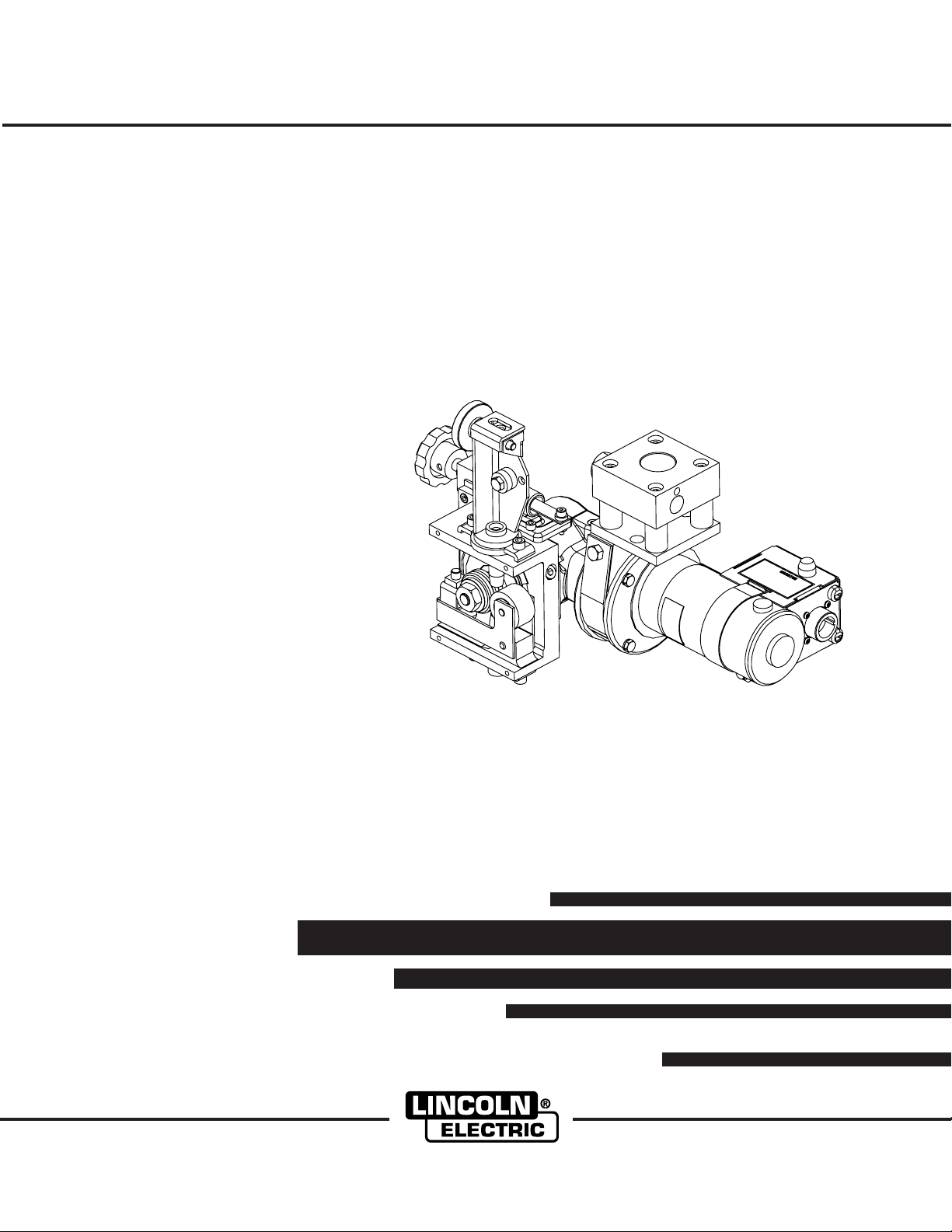
PRODUCT DESCRIPTION
1
PRODUCT SUMMARY
The Power Feed 10S series of Automatic Wire Drives
are designed for hard automation, submerged arc
welding. The heavy-duty gearbox and feed plate have
many years of proven reliability while a new permanent magnet motor has been added.
The Power Feed 10S wire drives consist of a high
torque motor and gearbox assembly with a heavy-duty
feed plate housing knurled drive rolls for positive,
accurate wire feeding of heavy welding wire. The
Power Feed 10S has many axes of rotation for ease
of fixturing and locating.
RECOMMENDED PROCESSES
• The Power Feed 10S series of wire drives are best
suited for submerged arc welding.
PROCESS LIMITATIONS
• MIG welding
• Robotic applications
EQUIPMENT LIMITATIONS
The Power Feed 10S series of wire drives cannot be
used with the NA3, NA-4, or NA-5 series of Lincoln
Automatics.
COMMON EQUIPMENT PACKAGES
Basic Package:
K2344-1 Power Wave 1000 AC/DC
K2362-1 PF-10A Controller
K2312-1 PF-10SF Wire Drive
Basic Package with optional kits:
K2311-1 PF-10SM Motor Retrofit Kit
K2370-1 PF-10S Wire Drive (includes Cross
Seam Adjuster and Automatic Flux
Hopper with hardware to connect to
TC-3 Travel Carriage)
K2282-1 System Interface (Phase Generator)
POWER FEED 10S
Page 9

2
GENERAL INFORMATION
DESIGN FEATURES
• Closed-loop speed control.
• Knurled drive rolls.
• Heavy cast aluminum gearbox housing and feed plate assembly.
• Wire straightener.
• 32Vdc permanent magnet, high torque motor.
• Conversion kit included to change speed range.
• Voltage sense leads included for precision welding performance.
LOCATION OF COMPONENTS
WIRE DRIVE AND COMPONENTS
2
ISOVIEW (REF. ONLY)
SIDE VIEW
MOTOR AND LEAD
CONNECTIONS
CENTERLINE OF WIRE
CENTERLINE OF WIRE
TOP VIEW
CENTERLINE
OF WIRE
CENTERLINE OF
MOUNTING BRACKET
POWER FEED 10S
FRONT VIEW
Page 10

3
SPECIFICATIONS
TECHNICAL SPECIFICATIONS - POWER FEED 10S
Spec. Type 142:1 Speed Ratio 95:1 Speed Ratio 57:1 Speed Ratio
3
K2312-1
MODEL
K2312-1
K2370-1
K2311-1
Process
Wire Size
Speed Solid Cored
Power Feed
10S
10-200 7/32 5/32
Wire Feeders - Input Voltage and Current
Voltage
32V DC
PHYSICAL DIMENSIONS
HEIGHT
12.0 in. (305 mm)
12.0 in. (305 mm)
8.0 in. (203 mm)
TEMPERATURE RANGES
OPERATING TEMPERATURE RANGE
-4°F to 104°F (-20°C to 40°C)
WELDING PROCESSES
Electrode Diameter Range
Output Range (Amperes)
Wire Size
Speed Solid Cored
10-300 1/8 5/32
WIDTH
14.0in (355mm)
14.0in (355mm)
6.0in (152mm)
STORAGE TEMPERATURE RANGE
Wire Size
Speed Solid Cored
10-450 1/16 3/32
Input Amperes
7 Amps (max.)
DEPTH
10.0in (254mm)
10.0in (254mm)
5.0in (127mm)
-40°F to 185°F (-40°C to 85°C)
Wire Feed Speed Range
WEIGHT
35.0lbs (15.9kg)
80.0lbs (36.3kg)
10.0lbs (4.5kg)
SAW
1/16 – 7/32" (1.6 – 5.6 mm)
200 - 1000
10 - 450 ipm (.25 – 11.43 m/minute)
POWER FEED 10S
Page 11

A-1
INSTALLATION
SAFETY PRECAUTIONS
Read this entire installation section before you
start installation.
WARNING
ELECTRIC SHOCK can kill.
• Only qualified personnel should perform this installation.
• Turn the input power OFF at the disconnect switch or fuse box before
working on this equipment. Turn off
the input power to any other equipment connected to the welding system at the disconnect switch or fuse
box before working on the equipment.
• Do not touch electrically hot parts.
-------------------------------------------------------------
NON-STANDARD SAFETY INFORMATION
A-1
CAUTION
The PF-10S series of wire drives may be at welding voltage potential when the output of the power
source is active.
------------------------------------------------------------------------
INPUT AND GROUND CONNECTIONS
Only a qualified electrician should connect the
POWER FEED 10S. Installation should be made in
accordance with the appropriate National Electrical
Code, all local codes and the information in this manual.
LOCATION AND MOUNTING
• The POWER FEED 10S will operate in harsh environments.
HIGH FREQUENCY PROTECTION
Locate the POWER FEED 10S away from radio controlled machinery.
POWER FEED 10S
Page 12

A-2
2.50
.50
.50
INSTALLATION
POWER WAVE AC/DC 1000AMP SUBARC
SYSTEM CONNECTIONS
(See Figure A.1)
1- Work cable connection
3- 14 pin wire feeder control cable
4- 5 pin Arclink control cable to user interface
7- Electrode cable connection
MOUNTING DIMENSIONS
The PF-10S can be mounted by using the four 3/8-16
tapped holes or the two 0.562 through holes. See
mounting hole locations (Figure A.2).
FIGURE A.1
POWER WAVE
AC/ DC 10 00
K2344-1
A-2
ARC 1
CONTROL
K1543-xx ARCLINK CONTROL CABLE
POWER FEED 10S
WIRE DRIVE
K2312-1
4.70
POWER FEED10SFC
CONT ROL B OX
K2362-1
3/8-16 T APPED HOLES
(4 PLACES)
1
3
2
WORK SENS E
LEAD
FIGURE A.2
2.50.62
.41
5
4
6
7
K1785-xx 14 14 PIN FEEDER CABLE
EL ECT R ODE
SENSE LEAD
SUBARC CONTACT
NOZZLE
K231-xxx
WORK
.50
8
A
R
C
1
WORK PIECE
4.26
2.69
CENTERLINE
OF WIRE
7.70
POWER FEED 10S
.96
O .562 (2 HOLES)
CENTERLINE OF
MOUNTING BRACKET
Page 13

A-3
INSTALLATION
CHANGING WIRE DRIVE CONFIGURATION
The POWER FEED-10S Wire Drives can be reconfigured to fit in any hard automation application.
The POWER FEED-10S Wire Drives can be reconfigured in such a way that the wire feed direction is
reversed. If this is the case, the motor leads must be
reversed so the wire will feed correctly. Follow these
instructions to reverse the motor polarity. (See Figure
A.3)
1. Remove all power from the POWER FEED-10S
Wire Drive.
A-3
5. Carefully disconnect the Motor leads from the harness by pulling the quick-connect terminals apart.
6. Reverse the motor leads and reconnect the quickconnect terminals (see Wiring Diagram).
7. Carefully replace the wire harness back into the
Connection Box and place back onto the Motor
housing locating over the Motor lead grommet.
Ensure that the tachometer leads are completely
covered by the Channel that snaps into the
Connection Box. The Connection Box assembly
should be pushed all the way up to the Motor-toGearbox Adapter Plate.
2. Disconnect the Control Cable from the POWER
FEED-10S Wire Drive Connection Box.
3. Loosen the fastener from the Band Strap to the
Connection Box, which secures the assembly to the
Motor housing, and expose the leads inside of the
Connection Box.
4. Locate the Motor leads. These leads will go from
the Motor to the Control Cable connector on the
inside of the Connection Box.
FIGURE A.3
8. Before securing the Connection Box to the Motor
housing with the Band Strap, ensure that none of
the harness leads are being pinched underneath
the edges of the Connection Box and Channel.
9. Place the Band Strap into the "T" slot on the side
of the Connection Box and wrap it around the
Motor housing.
10. Replace the fastener between the Band Strap and
the Connection Box. Tighten so that the Connection
Box cannot move on the Motor housing.
REMOVE CONNECTION BOX
TO CHANGE MOTOR POLARITY
R
O
T
A
T
E
LOOSEN SOCKET HEAD
SCREW TO ROTATE FEEDPLATE
LOOSEN HEX HEAD
SCREW ON GEARBOX
STRAP TO ROTATE THE
MOTOR AND GEARBOX ASSEMBLY
POWER FEED 10S
E
T
A
T
R
O
Page 14

A-4
INSTALLATION
A-4
ELECTRODE AND WORK
CONNECTIONS
Due to the Power Wave AC/DC”s ability to produce
either a DC positive, DC negative or AC output the electrode and work connections do not need to be reversed
for the different polarities. Additionally no DIP switch
changes are required to switch between the different
polarities. All of this is controlled internally by the Power
Wave AC/DC. The following directions apply to all polarities:
Connect a work lead of sufficient size (Per Table A.1)
and length between the "work" stud (located beneath
the spring loaded output cover on the front of the
machine) and the work. For convenience, the work lead
can be routed behind the left strain relief (under the
spring loaded output cover), along the channels, and
out the back of the machine. Be sure the connection to
the work makes tight metal-to-metal electrical contact.
The work piece connection must be firm and secure.
Excessive voltage drops caused by poor work piece
connections often result in unsatisfactory welding performance. To avoid interference problems with other
equipment and to achieve the best possible operation,
route all cables directly to the work and wire feeder.
Avoid excessive lengths and do not coil excess cable.
REMOTE SENSE LEAD SPECIFICATIONS
The Power Feed 10S has sense lead connections at
the Connection Box mounted to the motor. These
sense leads are critical to the accuracy of the Power
Wave welding process. Ring terminals are provided at
the ends of the leads. These leads must be extended
to the Work piece and the Electrode respectively. The
lead marked "TO WORK" should be extended and
connected to the work piece, while the lead marked
"TO ELECTRODE" should be extended and connected to the nozzle. These connections should be made
as close to the welding arc as possible. Use at least a
12 AWG wire with a proper sized ring terminal. Use a
screw with a lock washer and nut to make the connection, then insulate the connection with electrical tape.
Proper care should be taken to protect the sense
leads from becoming disconnected or damaged. The
loss of a sense lead connection can adversely affect
welding performance.
Connect the electrode cable to the "ELECTRODE" stud
on the power source (located behind the cover plate on
the lower left side). For convenience, the cable can be
routed through the oval hole in the left cable tray before
being connected to the output terminals. Connect the
other end of the electrode cable to the nozzle. Be sure
the connection makes tight metal-to-metal electrical
contact. The electrode cable should be sized according
to the specifications given in Table A.1.
TABLE A.1 - Output Cable Guidelines
Total Cable Length
ft (m)
Electrode and Work
Combined
0 (0) to 250 (76.2)
0 (0) to 250 (76.2)
Duty Cycle
80%
100%
Number of
Parallel Cables
2
3
Cable Size
Copper
4/0 (120 mm
3/0 (95 mm
2
)
2
)
When using inverter type power sources like the
Power Wave, use the largest welding (electrode and
work) cables that are practical. When pulsing, the
pulse current can reach very high levels. Voltage
drops can become excessive, leading to poor welding
characteristics, if undersized welding cables are used.
There are several different sense lead configurations
that can be used depending on the application. The
ELECTRODE sense lead (67) and the WORK sense
lead (21) are built into the wire drive control cable.
The system has multiple sense lead configurations
available. Consult the power source manual on how to
configure the power source DIP switches for the
sense leads.
CAUTION
Excessive voltage drops at the work piece connection often result in unsatisfactory pulse welding performance.
-----------------------------------------------------------------------POWER FEED 10S
Page 15

A-5
INSTALLATION
A-5
WELDING WITH MULTIPLE ARCS
Special care must be taken when more than one arc
is welding simultaneously on a single part. Arc blow
and arc interference may occur or be magnified. Each
power source requires a work lead from the work stud
to the welding fixture. Do not combine all of the work
leads into one lead. Always weld in a direction away
from the work leads. Connect all of the work sense
leads from each power source to the work piece at the
end of the weld, such that they are out of the path of
the weld current.
For the best results when pulse welding, set the wire
size and wire feed speed the same for all the arcs.
When these parameters are identical, the pulsing frequency will be the same, helping to stabilize the arcs.
FIGURE A.4
DIRECTION
OF TRA VEL
If the voltage sensing is enabled but the sense
leads are missing, improperly connected, or if the
electrode polarity switch is improperly configured
extremely high welding outputs may occur.
In extremely sensitive applications requiring voltage
sense leads, it may be necessary to route cables that
contain the sense leads away from the electrode and
work welding cables. For more information regarding
the placement of voltage sense leads, see the section
entitled "Welding with Multiple Independent Power
Waves."
CONNECT ALL SENSE
LEADS AT THE END
OF THE WEL D
POWER SOURCE
CONNECT AL L
WORK LEADS AT
THE BEGINNING OF
THE WELD
POWER SOURCE
POWER FEED 10S
Page 16

A-6
INSTALLATION
GEAR RATIO CONVERSION KITS (SEE
INSTRUCTIONS INCLUDED WITH CONVERSION KIT)
1. Remove the 2 hex head screws and the 2 slot head
screws holding the Motor to the Wire Drive Gearbox
assembly.
2. Remove existing Adapter Plate and Motor
Assembly.
3. Take the two long screws removed in step 1 and
screw one into each of the tapped holes located on
the face of fiber input helical gear. Insert the screws
through the full thickness of the gear, and using a
screwdriver wedged between the screws to prevent
rotation, remove the hex nut that holds the gear to
the shaft. Remove plain washer.
4. Pull the gear from the shaft using the screws as a
pulling device.
A-6
5. Be certain woodruff key is properly located on the
shaft. Screw the adapter plate and motor assembly
mounting screws into the new fiber input helical
gear from the stenciled side and place the gear on
the shaft. Replace plain washer, tighten the hex
nut, and remove the adapter plate and motor
assembly mounting screws from the gear.
6. Support the pinion properly and, with the proper
size punch, drive the roll pin that holds the pinion
out of the shaft. Pull the pinion off. Remove the
Ring Magnet from the pinion gear and snap it onto
the new pinion gear. Before installing the new pinion gear with the Ring Magnet onto the motor shaft,
ensure that the flat washer is located at the bottom
of the shaft. Install the new pinion and replace the
roll pin.
7. Cover the teeth of the motor pinion and the input
gear with a non-fluid molydisulfide type grease such
as Non-Fluid Oil Corporation’s A-29 Special/MS
Lubricant. This grease can be scooped from the
cavity of the gear case.
8. Reassemble the motor on the gearbox; make sure
the gears mesh properly and the adapter plate
locating bead is in its cavity. Replace and tighten
the four screws removed in step 1.
9. See the power source manual on how to configure the power source DIP switches for the new
gear ratio.
POWER FEED 10S
Page 17

C-1
ACCESSORIES
K2311-1 MOTOR CONVERSION KIT (FOR
142:1 NA STYLE WIRE DRIVES)--This conver-
tion kit converts old NA style wire drives.
1. Remove the 2 hex head screws and the 2 slot head
screws holding the Motor to the Wire Drive Gearbox
assembly.
2. Remove existing Adapter Plate and Motor Assembly.
3. The Conversion Kit Motor is shipped configured for a
142:1 gear ratio. The existing gearbox must be configured for a 142:1 gear ratio for the Conversion Kit to
assemble correctly. If both assemblies are not configured for the same gear ratio, this must be done
before continuing. (See Gear Ratio Conversion Kit
instructions.)
4. Cover the teeth of the new Motor pinion gear with a
non-fluid molydisulfide type grease such as Non-Fluid
Oil Corporation’s A-29 Special/MS Lubricant. This
grease can be scooped from the cavity of the gear
case First Chamber.
C-1
5. Reassemble the new Adapter Plate and Motor
Assembly on the Wire Drive Gearbox; making sure
the gears mesh properly and the Adapter Plate locating bead is in its cavity. Replace and tighten the 4
screws removed in step 1.
POWER FEED 10S
Page 18

D-1
MAINTENANCE
D-1
SAFETY PRECAUTIONS
WARNING
ELECTRIC SHOCK can kill.
• Only Qualified personnel should
perform this maintenance.
• Turn the input power OFF at the
disconnect switch or fuse box
before working on this equipment.
• Do not touch electrically hot parts.
ROUTINE MAINTENANCE
• Check weld cables, control cables and gas hoses for
cuts.
• Clean and tighten all weld terminals.
• Inspect and clean drive rolls and inner wire guide
and replace if worn.
SENSE LEAD FUSE
There should never be any current flowing through
the sense leads! There is a fuse located in the sense
lead circuit that is mounted in the wire drive
Connection Box which protects the sense lead circuit
from weld current due to incorrect configuration. If this
fuse ever opens, check the sense lead configuration to
ensure proper connections. The fuse must be
replaced with a comparable fuse with a rating of less
than 1 amp before welding. The fuse being open or
missing would have the same effect on the welding as
having a disconnected sense lead.
PERIODIC MAINTENANCE
• Every six months check the motor brushes. Replace
them if they are less than 1/4" long.
• Every year inspect the gearbox and coat the gear
teeth with a moly-disulfide filled grease. DO NOT
use graphite grease.
CALIBRATION SPECIFICATION
All calibration is factory set on the Power Feed 10S.
To verify the wire feed speed:
• Press the INCH DOWN switch and adjust the wire
feed speed to 100 in/min (2.54m/min).
• Measure the actual wire feed speed with a calibrated
wire feed speed tachometer.
• The measured wire feed speed should be within ±2%
of the set value.
POWER FEED 10S
Page 19

E-1
TROUBLESHOOTING
HOW TO USE TROUBLESHOOTING GUIDE
WARNING
Service and Repair should only be performed by Lincoln Electric Factory Trained Personnel.
Unauthorized repairs performed on this equipment may result in danger to the technician and
machine operator and will invalidate your factory warranty. For your safety and to avoid Electrical
Shock, please observe all safety notes and precautions detailed throughout this manual.
__________________________________________________________________________
E-1
This Troubleshooting Guide is provided to help you
locate and repair possible machine malfunctions.
Simply follow the three-step procedure listed below.
Step 1. LOCATE PROBLEM (SYMPTOM).
Look under the column labeled “PROBLEM (SYMPTOMS)”. This column describes possible symptoms
that the machine may exhibit. Find the listing that
best describes the symptom that the machine is
exhibiting.
Step 2. POSSIBLE CAUSE.
The second column labeled “POSSIBLE CAUSE” lists
the obvious external possibilities that may contribute
to the machine symptom.
Step 3. RECOMMENDED COURSE OF ACTION
This column provides a course of action for the
Possible Cause, generally it states to contact your
local Lincoln Authorized Field Service Facility.
If you do not understand or are unable to perform the
Recommended Course of Action safely, contact your
local Lincoln Authorized Field Service Facility.
CAUTION
If for any reason you do not understand the test procedures or are unable to perform the tests/repairs safely, contact your
Local Lincoln Authorized Field Service Facility for technical troubleshooting assistance before you proceed.
POWER FEED 10S
Page 20

E-2
TROUBLESHOOTING
Observe all Safety Guidelines detailed throughout this manual
E-2
PROBLEMS
(SYMPTOMS)
Drive rolls turn, but wire will not
feed or wire feeding is rough or
uneven.
Variable or "hunting" arc.
POSSIBLE AREAS OF
MISADJUSTMENT(S)
OUTPUT PROBLEMS
1. Wire jammed or kinked on route
through wire drive. Remove wire
from wire drive, then feed in new
wire. Note any obstruction.
2. Incorrect drives rolls and/or
guide tubes, or incorrect pressure setting. Ensure drive rolls
and/or guide tubes are stamped
with wire diameter being used.
Replace if necessary. Check for
proper pressure setting.
3. Worn drive rolls. Replace, or
reverse if split type.
4. Partially flashed or melted contact tip. Replace contact tip.
1. Contact tip worn or incorrect
size. Replace contact tip.
RECOMMENDED
COURSE OF ACTION
If all recommended possible areas
of misadjustments have been
checked and the problem persists,
contact your local Lincoln
Authorized Field Service Facility.
2. Worn or undersized work cables
or poor connections to work.
Inspect and repair, or replace as
necessary.
3. Loose electrode connections.
The following connections must
be tight: electrode cable to wire
drive and power source, work
cable to power source and work,
contact tip to nozzle.
4. Rusty electrode. Replace electrode.
CAUTION
If for any reason you do not understand the test procedures or are unable to perform the tests/repairs safely, contact your
Local Lincoln Authorized Field Service Facility for technical troubleshooting assistance before you proceed.
POWER FEED 10S
Page 21

F-1
DIAGRAMS
F-1
B
1234567
R
550
551
B
W
4
1
B
N.A.
(J800)
U
L3
8
5
8
N.A.
(J801)
5
8
1234567
842
843
515
1
4
500
L2
F1 .6A
M20368
8
TACH INTERFACE PC BD
ELECTRICAL SYMBOLS PER E1537
LEAD COLOR CODING
B – BLACK
R – RED
U – BLUE
W - WHITE
N
M
L
8
4
3
8
4
2
A
0
5
1
0
K
6
7
J
2
1
I
5
0
H
5
1
G
F
E
D
C
OUTPUT RECEPTACLE
5
5
B
5
5
A
L1
IRING DIAGRAM POWER FEED 10 S
W
WIRING DIAGRAM FOR POWER FEED 10S
P.M.
R
U
B
H
C
A
T
67
21
MOTOR/GEARBOX
FROM COMPONENT SIDE OF PC BOARD.
NOTES:
N.A. CAVITY NUMBERING SEQUENCE AS VIEWED
N.B. CAVITY NUMBERING SEQUENCE AS VIEWED
POWER FEED 10S
FROM LEAD SIDE OF CONNECTOR.
NOTE: This diagram is for reference only. It may not be accurate for all machines covered by this manual. The specific diagram for a particular code is pasted inside
the machine on one of the enclosure panels. If the diagram is illegible, write to the Service Department for a replacement. Give the equipment code number.
Page 22

F-2
DIMENSION PRINT
F-2
.50
.502.50.62
.41
3/8-16 TAPPED HOLES
(4 PLACES)
4.70
2.69
.50
2.50
CENTERLINE OF
MOUNTING BRACKET
.96
4.26
O .562 (2 HOLES)
13.56
CENTERLINE
OF WIRE
7.70
2.82
6.16
11.29
A
L12119
CENTERLINE OF WIRE
.21
ISO VIEW (REF.ONLY)
5.19
2.60
3.50
6.16
CENTERLINE OF W IRE
2.43
4.25
9.82
POWER FEED 10S
Page 23

NOTES
POWER FEED 10S
Page 24

WARNING
Spanish
AVISO DE
PRECAUCION
● Do not touch electrically live parts or
electrode with skin or wet clothing.
● Insulate yourself from work and
ground.
● No toque las partes o los electrodos
bajo carga con la piel o ropa mojada.
● Aislese del trabajo y de la tierra.
● Keep flammable materials away.
● Mantenga el material combustible
fuera del área de trabajo.
● Wear eye, ear and body protection.
● Protéjase los ojos, los oídos y el
cuerpo.
French
ATTENTION
German
WARNUNG
Portuguese
ATENÇÃO
Japanese
Chinese
Korean
Arabic
● Ne laissez ni la peau ni des vête-
ments mouillés entrer en contact
avec des pièces sous tension.
● Isolez-vous du travail et de la terre.
● Berühren Sie keine stromführenden
Teile oder Elektroden mit Ihrem
Körper oder feuchter Kleidung!
● Isolieren Sie sich von den
Elektroden und dem Erdboden!
● Não toque partes elétricas e elec-
trodos com a pele ou roupa molhada.
● Isole-se da peça e terra.
● Gardez à l’écart de tout matériel
inflammable.
● Entfernen Sie brennbarres Material!
● Mantenha inflamáveis bem guarda-
dos.
● Protégez vos yeux, vos oreilles et
votre corps.
● Tragen Sie Augen-, Ohren- und Kör-
perschutz!
● Use proteção para a vista, ouvido e
corpo.
READ AND UNDERSTAND THE MANUFACTURER’S INSTRUCTION FOR THIS EQUIPMENT AND THE CONSUMABLES TO BE
USED AND FOLLOW YOUR EMPLOYER’S SAFETY PRACTICES.
SE RECOMIENDA LEER Y ENTENDER LAS INSTRUCCIONES DEL FABRICANTE PARA EL USO DE ESTE EQUIPO Y LOS
CONSUMIBLES QUE VA A UTILIZAR, SIGA LAS MEDIDAS DE SEGURIDAD DE SU SUPERVISOR.
LISEZ ET COMPRENEZ LES INSTRUCTIONS DU FABRICANT EN CE QUI REGARDE CET EQUIPMENT ET LES PRODUITS A
ETRE EMPLOYES ET SUIVEZ LES PROCEDURES DE SECURITE DE VOTRE EMPLOYEUR.
LESEN SIE UND BEFOLGEN SIE DIE BETRIEBSANLEITUNG DER ANLAGE UND DEN ELEKTRODENEINSATZ DES HERSTELLERS. DIE UNFALLVERHÜTUNGSVORSCHRIFTEN DES ARBEITGEBERS SIND EBENFALLS ZU BEACHTEN.
Page 25

● Keep your head out of fumes.
● Use ventilation or exhaust to
remove fumes from breathing zone.
● Turn power off before servicing.
● Do not operate with panel open or
guards off.
WARNING
● Los humos fuera de la zona de res-
piración.
● Mantenga la cabeza fuera de los
humos. Utilice ventilación o
aspiración para gases.
● Gardez la tête à l’écart des fumées.
● Utilisez un ventilateur ou un aspira-
teur pour ôter les fumées des zones
de travail.
● Vermeiden Sie das Einatmen von
Schweibrauch!
● Sorgen Sie für gute Be- und
Entlüftung des Arbeitsplatzes!
● Mantenha seu rosto da fumaça.
● Use ventilação e exhaustão para
remover fumo da zona respiratória.
● Desconectar el cable de ali-
mentación de poder de la máquina
antes de iniciar cualquier servicio.
● Débranchez le courant avant l’entre-
tien.
● Strom vor Wartungsarbeiten
abschalten! (Netzstrom völlig öffnen; Maschine anhalten!)
● Não opere com as tampas removidas.
● Desligue a corrente antes de fazer
serviço.
● Não toque as partes elétricas nuas.
● No operar con panel abierto o
guardas quitadas.
● N’opérez pas avec les panneaux
ouverts ou avec les dispositifs de
protection enlevés.
● Anlage nie ohne Schutzgehäuse
oder Innenschutzverkleidung in
Betrieb setzen!
● Mantenha-se afastado das partes
moventes.
● Não opere com os paineis abertos
ou guardas removidas.
Spanish
AVISO DE
PRECAUCION
French
ATTENTION
German
WARNUNG
Portuguese
ATENÇÃO
Japanese
Chinese
Korean
Arabic
LEIA E COMPREENDA AS INSTRUÇÕES DO FABRICANTE PARA ESTE EQUIPAMENTO E AS PARTES DE USO, E SIGA AS
PRÁTICAS DE SEGURANÇA DO EMPREGADOR.
Page 26

• World's Leader in Welding and Cutting Products •
• Sales and Service through Subsidiaries and Distributors Worldwide •
Cleveland, Ohio 44117-1199 U.S.A. TEL: 216.481.8100 FAX: 216.486.1751 WEB SITE: www.lincolnelectric.com
 Loading...