

Lincoln Electric PF44, PF46 Operator's Manual

IM3053
02/2015
REV03
PF44 & PF46
OPERATOR’S MANUAL
ENGLISH
Lincoln Electric Bester Sp. z o.o.
ul. Jana III Sobieskiego 19A, 58-263 Bielawa, Poland
www.lincolnelectric.eu

English English
I
Declaration of conformity
13
Lincoln Electric Bester Sp. z o.o.
Declares that the welding machine:
PF44
PF46
conforms to the following directives:
2006/95/CEE, 2004/108/CEE
and has been designed in compliance with the
following standards:
EN 60974-5, EN 60974-10:2007
12.07.2013
Paweł Lipiński
Operations Director
Lincoln Electric Bester Sp. z o.o., ul. Jana III Sobieskiego 19A, 58-263 Bielawa, Poland
07/11

English English
II
12/05
THANKS!
For having chosen the QUALITY of the Lincoln Electric products.
• Please Examine Package and Equipment for Damage. Claims for material damaged in shipment must be notified
immediately to the dealer.
• For future reference record in the table below your equipment identification information. Model Name, Code &
Serial Number can be found on the machine rating plate.
Model Name:
******...***********.**********************************..
Code & Serial number:
*******.******************..
********************.*****..
Date & Where Purchased:
*************************...
*******
**.****************..
ENGLISH INDEX
Technical Specifications ...................................................................................................................................................... 1
Electromagnetic Compatibility (EMC) .................................................................................................................................. 2
Safety .................................................................................................................................................................................. 3
Introduction ......................................................................................................................................................................... 4
Installation and Operator Instructions .................................................................................................................................. 4
Location and Environment ............................................................................................................................................... 4
Duty cycle and Overheating ............................................................................................................................................. 4
Input Supply Connection .................................................................................................................................................. 4
Controls and Operational Features .................................................................................................................................. 5
Guide’s Marking Interface ................................................................................................................................................ 7
Interface Description ........................................................................................................................................................ 9
Welding Parameters Bar .................................................................................................................................................. 9
Welding Program Choice ............................................................................................................................................... 11
User Settings ................................................................................................................................................................. 12
The Settings and Configuration Menu ........................................................................................................................... 17
USB Memory (PF46 only) .............................................................................................................................................. 27
Welding SMAW (MMA) Process .................................................................................................................................... 29
Gouging ......................................................................................................................................................................... 30
Welding GTAW / GTAW-PULSE Process ..................................................................................................................... 31
Welding GMAW, FCAW-GS and FCAW-SS Process in non-synergic mode ................................................................. 33
Welding GMAW and FCAW-GS Process in synergic mode CV .................................................................................... 35
Welding GMAW-P Process in synergic mode ................................................................................................................ 36
Aluminum Welding GMAW- PP Process in synergic mode ........................................................................................... 38
Welding STT® Process................................................................................................................................................... 40
Wire Spool Loading ....................................................................................................................................................... 42
Loading the Electrode Wire ........................................................................................................................................... 44
Adjustments of Brake Torque of Sleeve ........................................................................................................................ 44
Adjusting Pressure Roll Force ....................................................................................................................................... 45
Inserting Electrode Wire into Welding Gun .................................................................................................................... 45
Changing Driving Rolls .................................................................................................................................................. 45
Gas Connection ............................................................................................................................................................. 46
Maintenance .................................................................................................................................................................. 46
Error’s Message ............................................................................................................................................................ 47
WEEE................................................................................................................................................................................ 48
Spare Parts ....................................................................................................................................................................... 48
Electrical Schematic .......................................................................................................................................................... 48
Suggested Accessories ..................................................................................................................................................... 49
Connection Diagram ......................................................................................................................................................... 50

English English
1
Technical Specifications
NAME INDEX
PF44 K14108-1
PF46 K14109-1
INPUT
Input Voltage U1 Input Amperes I1 EMC Class
40Vdc 4A A
RATED OUTPUT
Duty Cycle 40°C
(based on a 10 min. period)
Output Current
100% 385A
60% 500A
OUTPUT RANGE
Welding Current Range Peak Open Circuit Voltage
5 ÷ 500A 113Vdc or Vac peak
DIMENSION
Weight Height Width Length
18,5 kg 460 mm 300 mm 640 mm
WIRE FEED SPEED RANGE / WIRE DIAMETER
WFS Range Drive Rolls
Drive roll
diameter
Solid Wires Aluminum Wires Cored Wires
1 ÷ 22 m/min 4 Ø37 0.8 ÷ 1.6 mm 1.0 ÷ 1.6 mm 0.9 ÷ 1.6 mm
Protection Rating Maximum Gas Pressure Operating Temperature Storage Temperature
IP23 0,5MPa (5 bar) from -10°C to +40°C from -25°C to 55°C

English English
2
Electromagnetic Compatibility (EMC)
01/11
This machine has been designed in accordance with all relevant directives and standards. However, it may still generate
electromagnetic disturbances that can affect other systems like telecommunications (telephone, radio, and television) or
other safety systems. These disturbances can cause safety problems in the affected systems. Read and understand
this section to eliminate or reduce the amount of electromagnetic disturbance generated by this machine.
This machine has been designed to operate in an industrial area. To operate in a domestic area it is
necessary to observe particular precautions to eliminate possible electromagnetic disturbances. The
operator must install and operate this equipment as described in this manual. If any electromagnetic
disturbances are detected the operator must put in place corrective actions to eliminate these disturbances
with, if necessary, assistance from Lincoln Electric.
Before installing the machine, the operator must check the work area for any devices that may malfunction because of
electromagnetic disturbances. Consider the following.
• Input and output cables, control cables, and telephone cables that are in or adjacent to the work area and the
machine.
• Radio and/or television transmitters and receivers. Computers or computer controlled equipment.
• Safety and control equipment for industrial processes. Equipment for calibration and measurement.
• Personal medical devices like pacemakers and hearing aids.
• Check the electromagnetic immunity for equipment operating in or near the work area. The operator must be sure
that all equipment in the area is compatible. This may require additional protection measures.
• The dimensions of the work area to consider will depend on the construction of the area and other activities that are
taking place.
Consider the following guidelines to reduce electromagnetic emissions from the machine.
• Connect the machine to the input supply according to this manual. If disturbances occur if may be necessary to take
additional precautions such as filtering the input supply.
• The output cables should be kept as short as possible and should be positioned together. If possible connect the
work piece to ground in order to reduce the electromagnetic emissions. The operator must check that connecting
the work piece to ground does not cause problems or unsafe operating conditions for personnel and equipment.
• Shielding of cables in the work area can reduce electromagnetic emissions. This may be necessary for special
applications.
WARNING
EMC classification of this product is class A in accordance with electromagnetic compatibility standard EN 60974-10 and
therefore the product is designed to be used in an industrial environment only.
WARNING
The Class A equipment is not intended for use in residential locations where the electrical power is provided by the public
low-voltage supply system. There may be potential difficulties in ensuring electromagnetic compatibility in those
locations, due to conducted as well as radiated disturbances.
English English
3
Safety
01/11
WARNING
This equipment must be used by qualified personnel. Be sure that all installation, operation, maintenance and repair
procedures are performed only by qualified person. Read and understand this manual before operating this equipment.
Failure to follow the instructions in this manual could cause serious personal injury, loss of life, or damage to this
equipment. Read and understand the following explanations of the warning symbols. Lincoln Electric is not responsible
for damages caused by improper installation, improper care or abnormal operation.
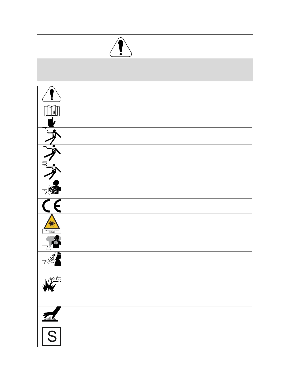
WARNING: This symbol indicates that instructions must be followed to avoid serious personal injury,
loss of life, or damage to this equipment. Protect yourself and others from possible serious injury or
death.
READ AND UNDERSTAND INSTRUCTIONS: Read and understand this manual before operating
this equipment. Arc welding can be hazardous. Failure to follow the instructions in this manual could
cause serious personal injury, loss of life, or damage to this equipment.
ELECTRIC SHOCK CAN KILL: Welding equipment generates high voltages. Do not touch the
electrode, work clamp, or connected work pieces when this equipment is on. Insulate yourself from
the electrode, work clamp, and connected work pieces.
ELECTRICALLY POWERED EQUIPMENT: Turn off input power using the disconnect switch at the
fuse box before working on this equipment. Ground this equipment in accordance with local electrical
regulations.
ELECTRICALLY POWERED EQUIPMENT: Regularly inspect the input, electrode, and work clamp
cables. If any insulation damage exists replace the cable immediately. Do not place the electrode
holder directly on the welding table or any other surface in contact with the work clamp to avoid the
risk of accidental arc ignition.
ELECTRIC AND MAGNETIC FIELDS MAY BE DANGEROUS: Electric current flowing through any
conductor creates electric and magnetic fields (EMF). EMF fields may interfere with some
pacemakers, and welders having a pacemaker shall consult their physician before operating this
equipment.
CE COMPLIANCE: This equipment complies with the European Community Directives.
ARTIFICIAL OPTICAL RADIATION: According with the requirements in 2006/25/EC Directive and
EN 12198 Standard, the equipment is a category 2. It makes mandatory the adoption of Personal
Protective Equipments (PPE) having filter with a protection degree up to a maximum of 15, as
required by EN169 Standard.
FUMES AND GASES CAN BE DANGEROUS: Welding may produce fumes and gases hazardous to
health. Avoid breathing these fumes and gases. To avoid these dangers the operator must use
enough ventilation or exhaust to keep fumes and gases away from the breathing zone.
ARC RAYS CAN BURN: Use a shield with the proper filter and cover plates to protect your eyes from
sparks and the rays of the arc when welding or observing. Use suitable clothing made from durable
flame-resistant material to protect you skin and that of your helpers. Protect other nearby personnel
with suitable, non-flammable screening and warn them not to watch the arc nor expose themselves to
the arc.
WELDING SPARKS CAN CAUSE FIRE OR EXPLOSION: Remove fire hazards from the welding
area and have a fire extinguisher readily available. Welding sparks and hot materials from the welding
process can easily go through small cracks and openings to adjacent areas. Do not weld on any
tanks, drums, containers, or material until the proper steps have been taken to insure that no
flammable or toxic vapors will be present. Never operate this equipment when flammable gases,
vapors or liquid combustibles are present.
WELDED MATERIALS CAN BURN: Welding generates a large amount of heat. Hot surfaces and
materials in work area can cause serious burns. Use gloves and pliers when touching or moving
materials in the work area.
SAFETY MARK: This equipment is suitable for supplying power for welding operations carried out in
an environment with increased hazard of electric shock.
English English
4
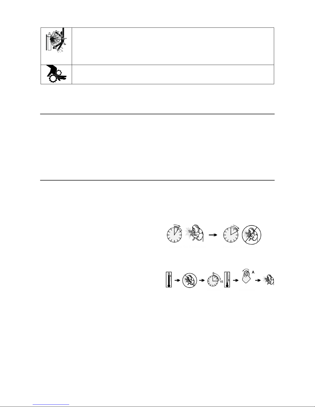
CYLINDER MAY EXPLODE IF DAMAGED: Use only compressed gas cylinders containing the
correct shielding gas for the process used and properly operating regulators designed for the gas and
pressure used. Always keep cylinders in an upright position securely chained to a fixed support. Do
not move or transport gas cylinders with the protection cap removed. Do not allow the electrode,
electrode holder, work clamp or any other electrically live part to touch a gas cylinder. Gas cylinders
must be located away from areas where they may be subjected to physical damage or the welding
process including sparks and heat sources.
MOVING PARTS ARE DANGEROUS: There are moving mechanical parts in this machine, which can
cause serious injury. Keep your hands, body and clothing away from those parts during machine
starting, operating and servicing.
The manufacturer reserves the right to make changes and/or improvements in design without upgrade at the same time
the operator’s manual.
Introduction
PF44 and PF46 are digital wire feeders which have been
designed to work with all Lincoln Electric power sources
using ArcLink® protocol to communication.
Digital wire feeders allow the welding:
• GMAW (MIG/MAG)
• FCAW-GS / FCAW-SS
• SMAW (MMA)
• GTAW (arc ignition using lift TIG)
Recommended equipment, which can be bought by
user, was mentioned in the chapter "Accessories".
Installation and Operator Instructions
Read this entire section before installation or operation
of the machine.
Location and Environment
This machine will operate in harsh environments.
However, it is important that simple preventative
measures are followed to assure long life and reliable
operation.
• Do not place or operate this machine on a surface
with an incline greater than 15° from horizontal.
• Do not use this machine for pipe thawing.
• This machine must be located where there is free
circulation of clean air without restrictions for air
movement.
• Dirt and dust that can be drawn into the machine
should be kept to a minimum.
• This machine has a protection rating of IP23. Keep
it dry when possible and do not place it on wet
ground or in puddles.
• Locate the machine away from radio controlled
machinery. Normal operation may adversely affect
the operation of nearby radio controlled machinery,
which may result in injury or equipment damage.
Read the section on electromagnetic compatibility in
this manual.
• Do not operate in areas with an ambient
temperature greater than 40°C.
Duty cycle and Overheating
The duty cycle of a welding machine is the percentage
of time in a 10 minute cycle at which the welder can
operate the machine at rated welding current.
Example: 60% duty cycle
Welding for 6 minutes. Break for 4 minutes.
Excessive extension of the duty cycle will cause the
thermal protection circuit to activate.
Minutes or decrease
Duty Cycle
Input Supply Connection
Check the input voltage, phase, and frequency of the
power source that will be connected to this wire feeder.
The allowable input voltage source is indicated on the
rating plate of the wire feeder. Verify the connection of
grounding wires from the power source to the input
source.
English English
5
Controls and Operational Features
1
23
5
4
7
8
9
12
10
11
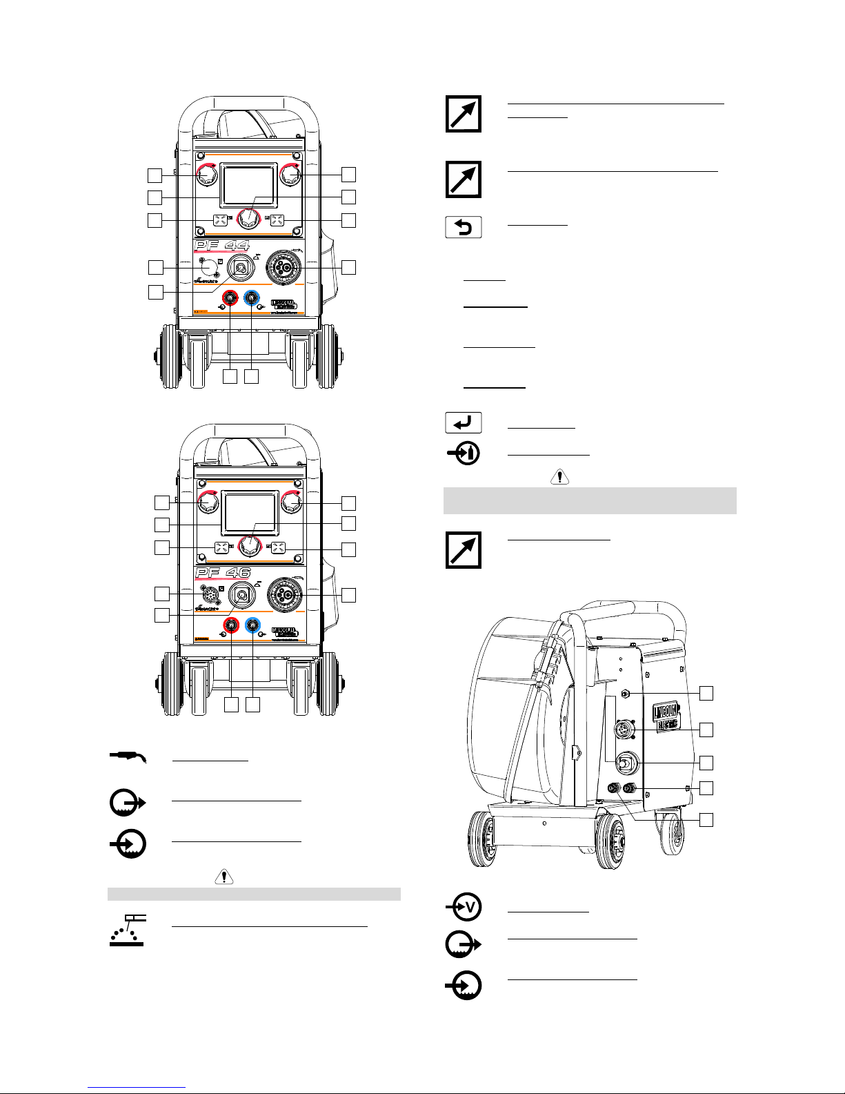
Figure 1
1
23
6
4
10
7
8
9
12
11
Figure 2.
1. EURO Socket: For connecting a welding
gun (for GMAW / FCAW-SS process).
2. Quick Connect Coupling: Coolant outlet
(supplies cool coolant to the gun).
3. Quick Connect Coupling: Coolant inlet
(takes warm coolant from the gun).
WARNING
Maximum coolant pressure is 5,0 bar.
4. Output Socket for the Welding Circuit: For
connecting an electrode holder with lead.
5. Remote Control Connector Plug (optional,
PF44 only): To install Remote Control Kit. It
can be purchased separately. See
"Accessories" chapter.
6. Remote Control Receptacle (PF46 only): To
connection Remote Control or Cross Switch
Gun.
7. Left Button:
•••• Cancel
•••• Back.
8. Display: Parameters of welding process are shown.
9. Left Control: The value of the parameter in the
upper left side of display [8] is adjusted.
10. Right Control: The value of the parameter in the
upper right side of display [8] is adjusted.
11. Set Control: Type of welding procedure and welding
settings is changed by this Control.
12. Right Button: Confirm change.
13. Gas Connector: Connection for gas line.
WARNING
The welding machine supports all suitable shielding
gases at a maximum pressure of 5,0 bar.
14. Control Receptacle: 5 pins receptacle for
wire feeder connection. To communication
wire feeder with power source is used
ArcLink® protocol.
13
14
15
16
17
Figure 3.
15. Current Socket: Input power connection.
16. Quick Connect Coupling: Coolant outlet
(takes warm coolant from welding machines
to cooler).
17. Quick Connect Coupling: Coolant inlet
(supplies cool coolant from cooler to the
welding machines).
English English
6
WARNING
Maximum coolant pressure is 5,0 bar.
To ensure failure-free work and right flow of coolant,
use only coolant that is recommended by the
manufacturer of welding gun or cooler.
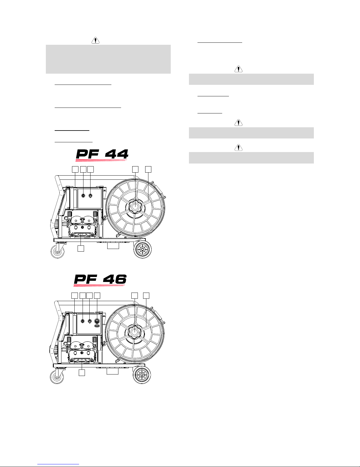
18. Gas Flow Regulator Plug: Gas Flow Regulator can
be purchased separately. See "Accessories"
chapter.
19. Cold Inch / Gas Purge Switch: This switch enables
wire feeding or gas flow without turning on output
voltage.
20. Lighting Switch.
21. USB Receptacle: To connection the USB memory.
18 19 22
24
20 23
Figure 4.
18 19 20 21 22 23
24
Figure 5.
22. Wire Spool Support: Maximum 15kg spools.
Accepts plastic, steel and fiber spools onto 51mm
spindle. Also accepts Readi-Reel® type spools onto
included spindle adapter.
WARNING
Be sure that wire spool case has to be completely
closed during welding.
23. Spooled Wire: The machine does not include a
spooled wire.
24. Wire Drive: 4-Roll wire drive.
WARNING
The wire drive door and wire spool case have to be
completely closed during welding.
WARNING
Not use handle to move the machine during work. See
"Accessories" chapter.
English English
7
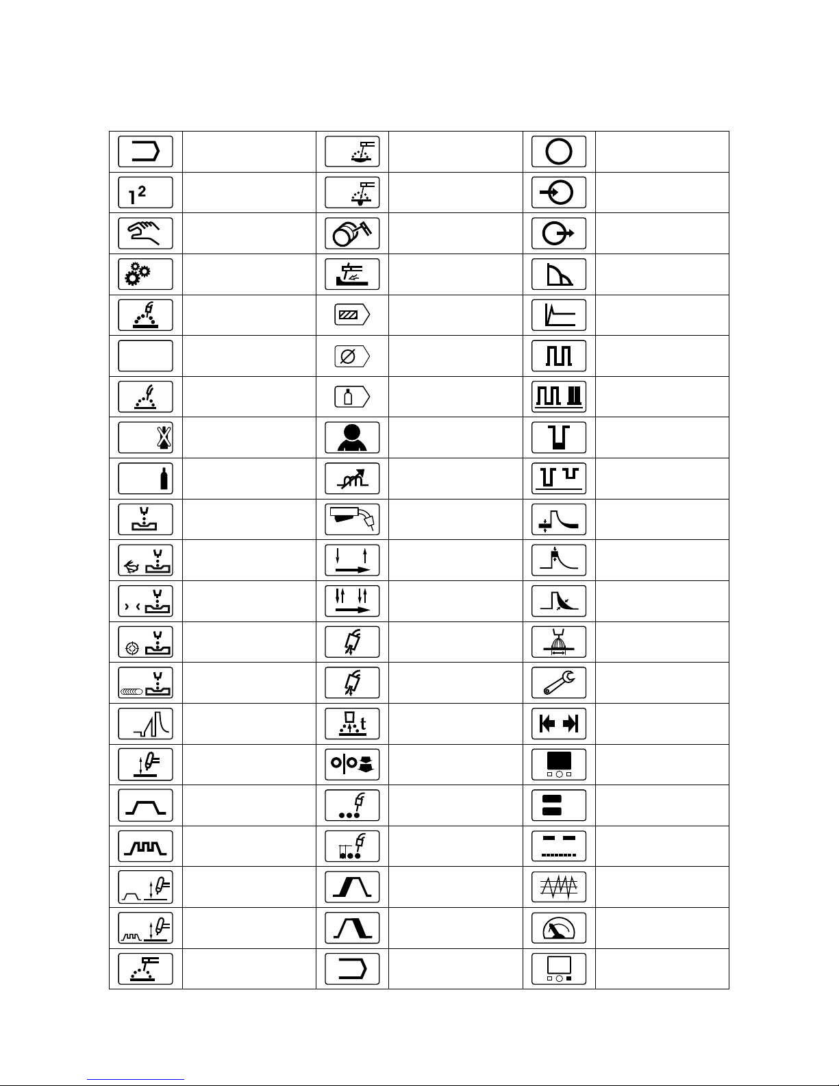
Guide’s Marking Interface
Description of the abridged user interface in "Quick Guide" chapter. See "Spare Part".
Table 1. Symbols description
Select Welding Process
Soft
SMAW-Soft Process
M
Memory
(PF46 only)
3
.
.
.
Select Welding Program
Crisp
SMAW-Crisp Process
M
Save to the User
Memory
(PF46 only)
Non-synergic Programs
SMAW-Pipe Process
M
Recall from the User
Memory
(PF46 only)
Syner
Synergic Programs
Gouging
Arc Force
GMAW Process
(MIG/MAG)
Electrode Wire Type
Selection
A
Hot Start
MODE
POW ER
GMAW Process –
POWER MODE®
Wire Size (diameter)
Selection
Frequency Settings
(GTAW-PULSE)
FCAW Process
Gas Selection
Frequency
(GTAW-PULSE)
FCAW-S
FCAW-SS Process
User Settings
Background Settings
(GTAW-PULSE)
FCAW-G
FCAW-GS Process
Pinch
Background Current
(GTAW-PULSE)
GMAW-P Process
Select Function of Gun
Trigger (2-Step / 4-Step)
Background Current
(STT®)
GMAW-P Process
RapidArc® Program
2-Step
Peak Current
(STT®)
X
GMAW-P Process
RapidX® Program
4-Step
TailOut
(STT®)
GMAW-P process
Precision Pulse™
Program
t1
Preflow Time
UltimArc™
GMAW-P Process
Pulse-On-Pulse®
Program
t2
Postflow Time
Setting and
Configuration Menu
STT
STT® Process
Burnback Time
Memory Limits
(PF46 only)
GTAW Process
(TIG)
Run-in WFS
Display Configuration
Settings
GTAW Welding
Spot Welding Settings
A
V
Big Meters Menu
(factory default)
GTAW-PULSE Welding
t
Spot Timer
Standard Menu
GTAW Program
Start Procedure
Weld Score™ Menu
GTAW-PULSE Program
Crater Procedure
True Energy™ Menu
SMAW Process
(MMA)
A/B
A/B Procedure
(PF46 only)
Assign Function
to the Right Button
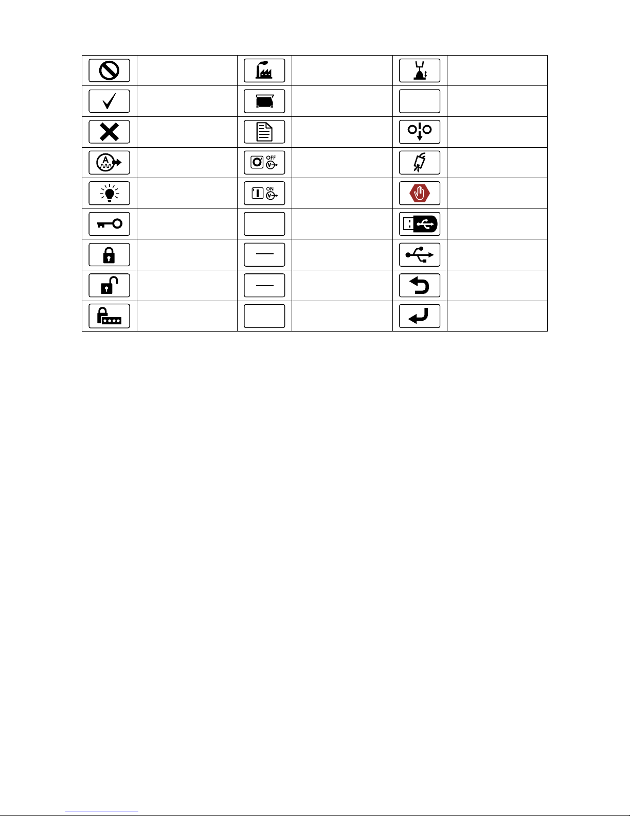
English English
8
Disabled
Restore Factory Setting
Trim
Check Mark
?
View Software and
Hardware Version
Information
kW
Power in kW
Resignation Mark
Setup Menu
Cold Feed
Wave Controls
Switch Off Output
Voltage
MMA/TIG only)
Gas Purge
Brightness Level
Switch On Output
Voltage
(MMA/TIG only)
Error
Lock / Unlock
A
Welding Current
USB Memory
(PF46 only)
Locked
min
m
Wire Feed Speed
in [m/min]
USB Memory
is connected
(PF46 only)
Unlocked
min
in
Wire Feed Speed
in [in/min]
ESCape Button
Set Passcode
V
Welding Voltage
Confirm Button
English English
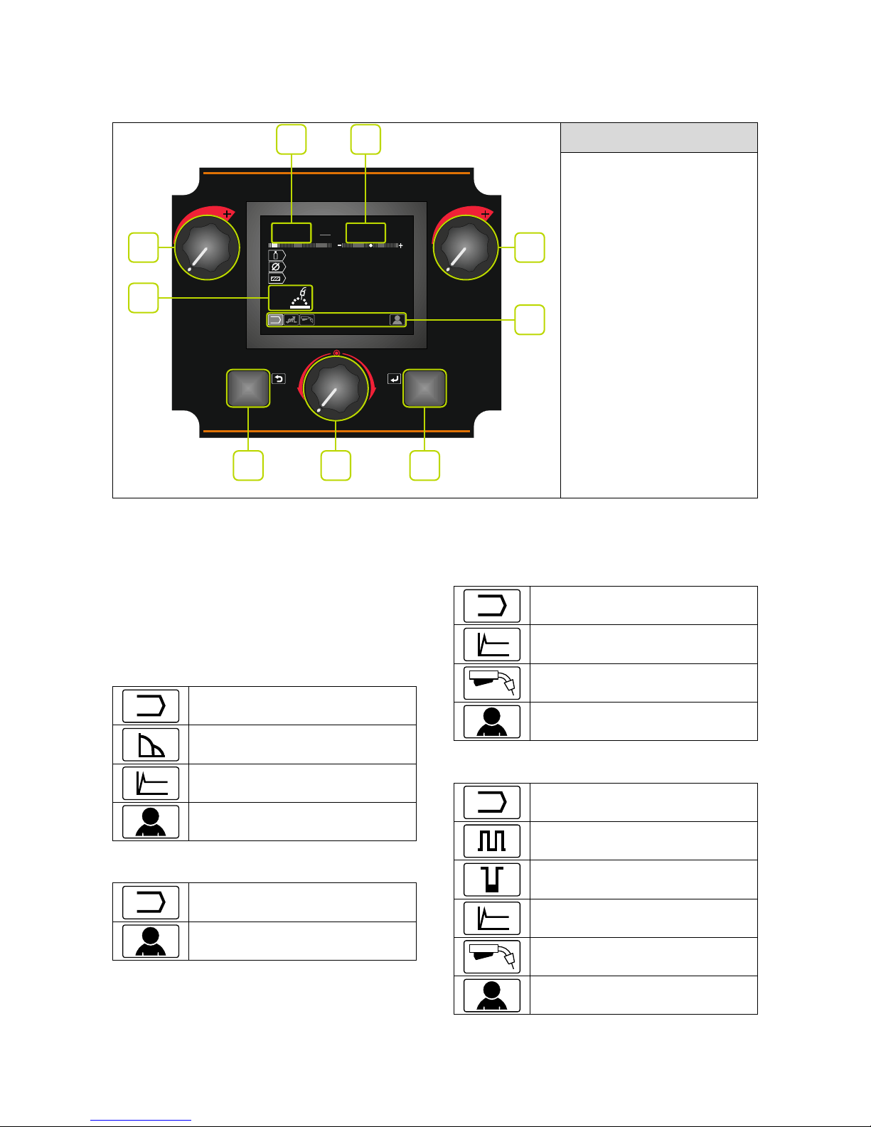
9
Interface Description
Table 2. Interface Components and Functions
v
min
m
125A
22.5V
1.2
Steel
ArCO2
21
109
7 11 12
25 26
27
28
28.65.51
Figure 6.
Functions of Interface
Components
7. Cancel / back.
9. Changing Parameter Value
[25].
10. Changing Parameter Value
[26].
11. Selection and changing the
Welding Settings.
12. Change Confirmation.
25. The Parameter Value in the
upper left side of display.
26. The Parameter Value in the
upper right side of display.
27. Welding Parameters Bar.
28. Welding Program.
Welding Parameters Bar
The Welding Parameters Bar enables:
•••• Welding Program change.
•••• Wave Control Value change.
•••• The gun’s trigger function change (GMAW,
GMAW-P, FCAW, STT, GTAW only).
•••• Add or hide functions and welding parameters – User
Settings
Table 3. SMAW Welding Parameters Bar – factory
default
Welding Process Choice
Arc Force
A
Hot Start
(SMAW Soft and SMAW Crisp only)
User Settings
Table 4. Gouging Welding Parameters Bar – factory
default
Welding Process Choice
User Settings
Table 5. GTAW Welding Parameters Bar – factory
default
Welding Process Choice
A
Hot Start
The function of the gun’s trigger change
User Settings
Table 6. GTAW-P Welding Parameters Bar – factory
default
Welding Process Choice
Frequency Settings
Background Settings
A
Hot Start
The function of the gun’s trigger change
User Settings
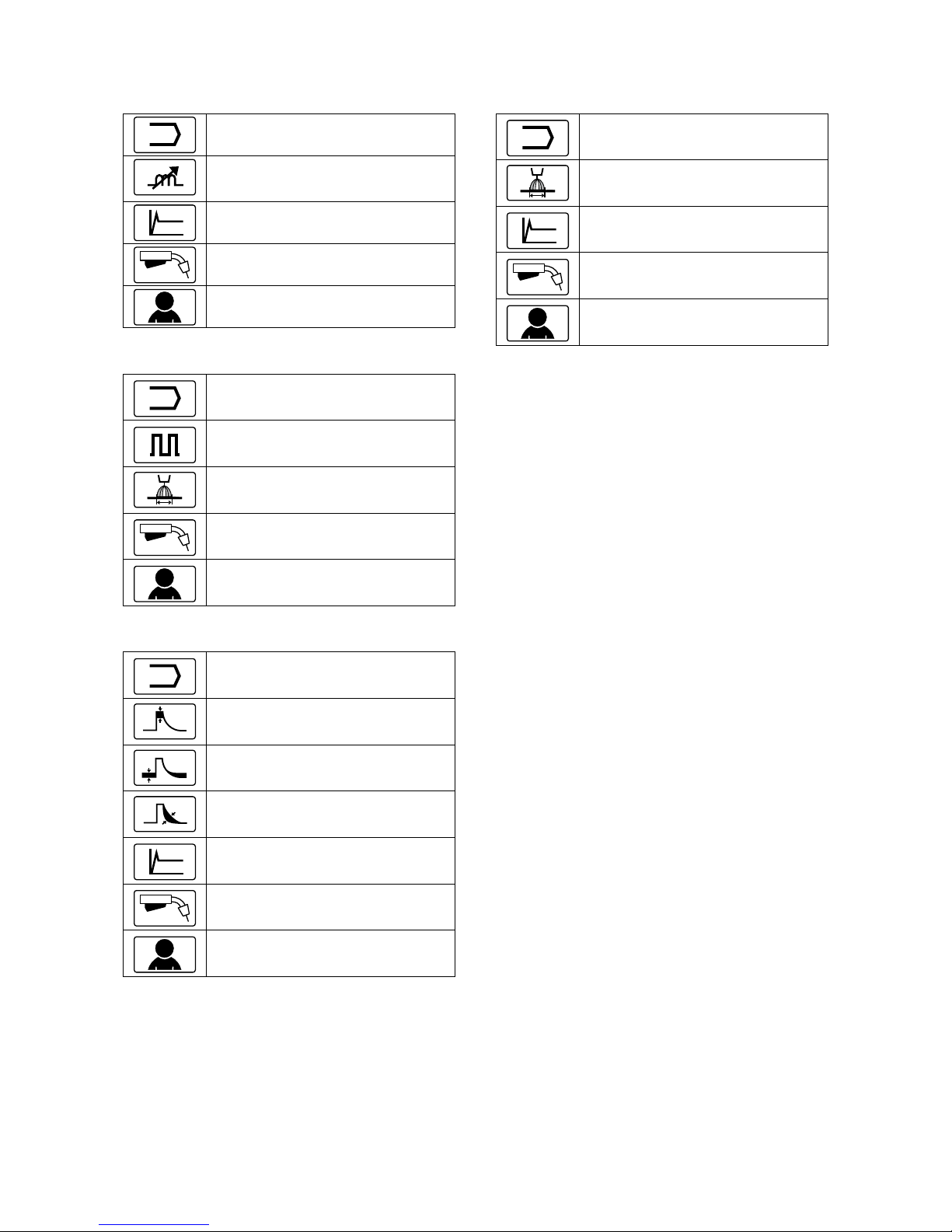
English English
10
Table 7. GMAW and FCAW Welding Parameters
Bar – factory default
Welding Process Choice
Pinch *
A
Hot Start
The function of the gun’s trigger change
User Settings
Table 8. GMAW-P Welding Parameters Bar – factory
default
Welding Process Choice
Frequency
(Pulse-On-Pulse® only)
UltimArc™
(except for Pulse-On-Pulse®)
The function of the gun’s trigger change
User Settings
Table 9. Non-synergic STT® Welding Parameters
Bar – factory settings
Welding Process Choice
Peak Current
Background Current
TailOut
A
Hot Start
The function of the gun’s trigger change
User Settings
Table 10. Synergic STT® Welding Parameters Bar –
factory settings
Welding Process Choice
UltimArc™
A
Hot Start
The function of the gun’s trigger change
User Settings
English English
11
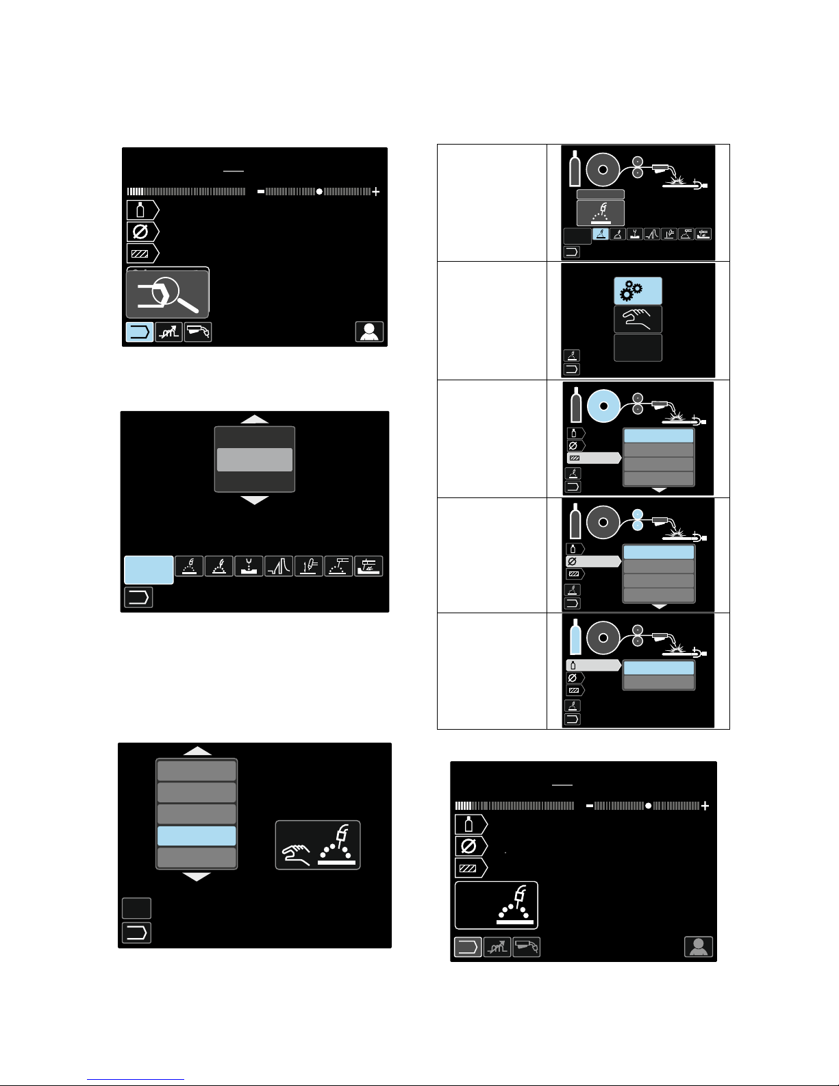
Welding Program Choice
To select the Welding Program:
• Use the Set Control [11] to highlight the Welding
Process Choice icon.
v
33.0
min
m
125
A
22.5
V
1.0
Steel
ArCO2
21
5.51
Figure 7.
• Press the Set Control [11] – Welding Program
Choice Menu is shown on the display.
9
10
11
1
2
3
.
.
.
Figure 8.
•••• Use the Set Control [11] to highlight the Welding
Program Choice icon – Figure 8.
•••• Press the Set Control [11].
•••• Use the Set Control [11] to highlight the Welding
Program Number.
Note: The list of available programs depends on the
power source.
1
2
3
.
.
.
4
5
6
7
8
GMAW CV
Figure 9.
•••• Confirm the select – press the Right Button [12].
If a user does not know the Welding Program Number, it
can be searched. In that case in subsequent steps are
given:
•••• The Welding
Process
1
2
3
.
.
.
MIG
GMAW
•••• Synergic /
Non-synergic
Process
MO DE
POWER
Syner
•••• The Electrode
Wire Type
GMAW
Steainless
Steel
Alum inum
Cored Wire
•••• The Electrode
Wire Diameter
GMAW
0.9
0.8
1.0
1.2
•••• The Shielding
Gas
GMAW
CO2AR
CO2
In consequence the definite Welding Program is
received.
v
29.1
min
m
0
A
0.0
V
0.8
Steel
CO2
93
5.51
Figure 10
English English
12
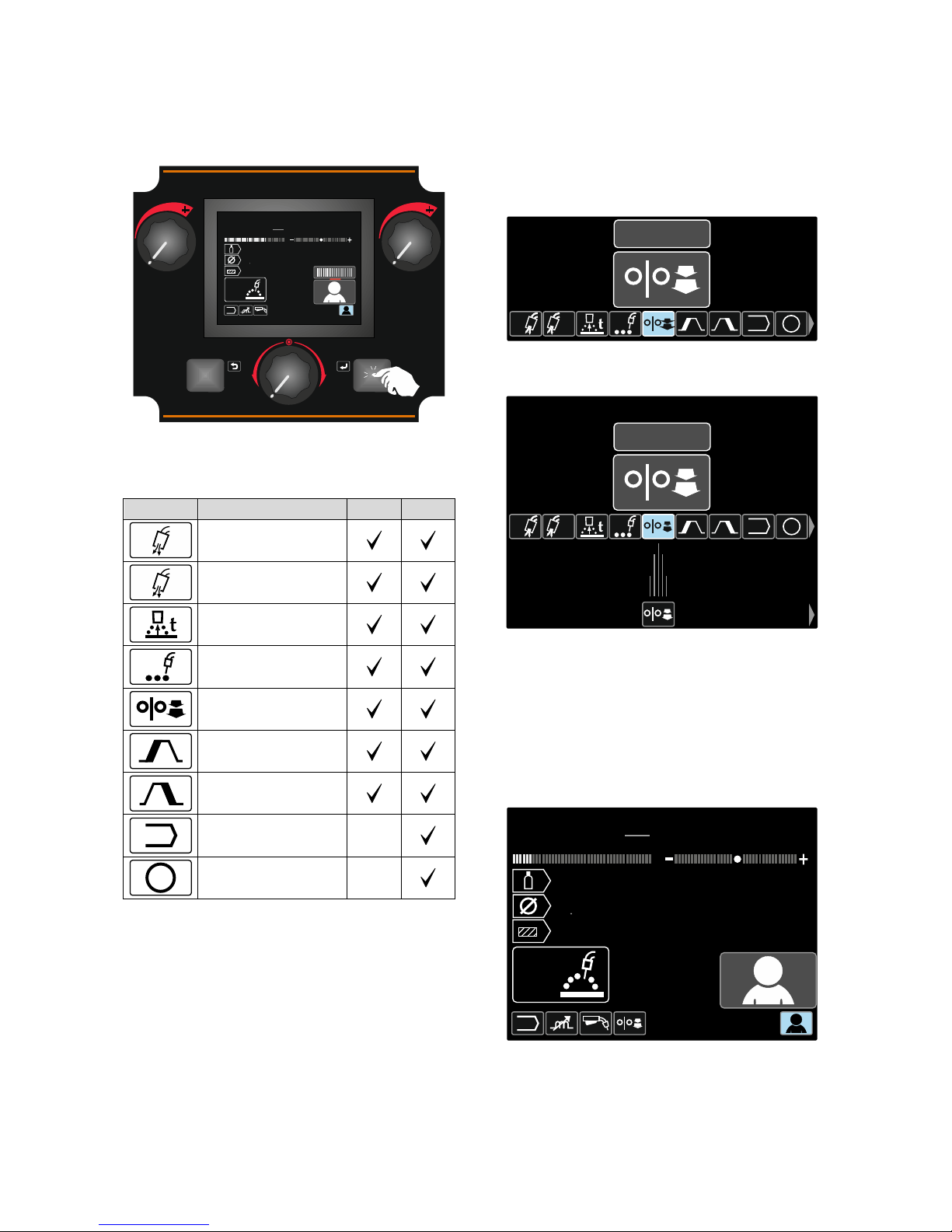
User Settings
To access the User Settings, mark the User Settings
icon [11], press and hold for 1 second the Right Button
[12].
v28.6
min
m
125
A
22.5
V
1.2
Steel
CO2AR
21
1s
5.51
Figure 11.
The User Setting Menu enables to add the additional
function and / or parameters to the Welding Parameters
Bar [27]. Depending on the Wire Feeder, may be added:
Icon Parameter PF44 PF46
t1
Preflow
t2
Postflow
Burnback Time
Spot Welding
Run-In WFS
Start Procedure
Crater Procedure
A/B
A/B Procedure
-
M
User Memory
-
Note: To change the Parameters or Functions Value,
theirs icons had to be added to the Welding Parameters
Bar [27].
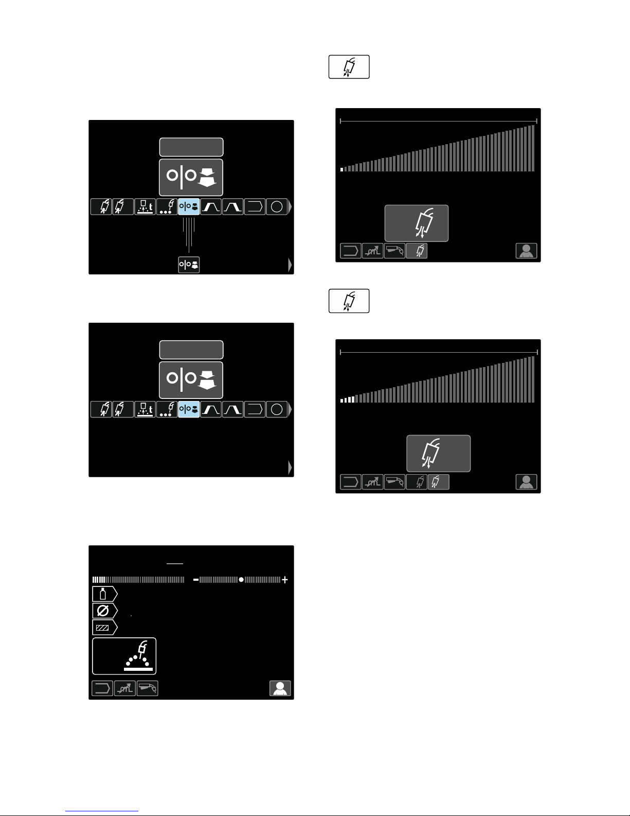
To add the Parameter or Function to the Welding
Parameters Bar [27]:
•••• Access to the User Settings (see the Figure 11).
•••• Use the Set Control [11] to highlight the parameter or
function icon which will be added to the Welding
Parameters Bar [27], for example Run-in WFS.
t1 t2
A/B M
OFF
Figure 12.
•••• Press the Set Button [11]. Run-in WFS icon will drop.
t1 t2
A/B M
OFF
Figure 13.
Note: To remove the icon press the Set Control [11]
once again.
Note: To cancel the change and exit the User
Settings Menu – press the Left Button [7].
•••• Confirm the select – press the Right Button [12].
The User Settings Menu is closed. The Selected
parameters or function is added to the Welding
Parameters Bar [27].
v
28.6
125
A
22.5
V
1.2
Steel
ArCO2
21
min
m
5.51
Figure 14.
English English
13
To remove the selected parameter or function from the
Welding Parameters Bar [27]:
•••• Access to the User Settings.
•••• Use the Set Control [11] to highlight the selected
parameter or function icon which will was added to
the Welding Parameters Bar [27].
t1 t2
A/B M
OFF
Figure 15.
•••• Press the Set Control [11] – The selected icon will
disappear from the display bottom.
t1 t2
A/B M
OFF
Figure 16.
•••• Confirm the select – press the Right Button [12].
The User Settings Menu is closed. The Selected
parameters or function was disappeared from the
Welding Parameters Bar [27]
v
28.6
125
A
22.5
V
1.2
Steel
ArCO2
21
min
m
5.51
Figure 17.
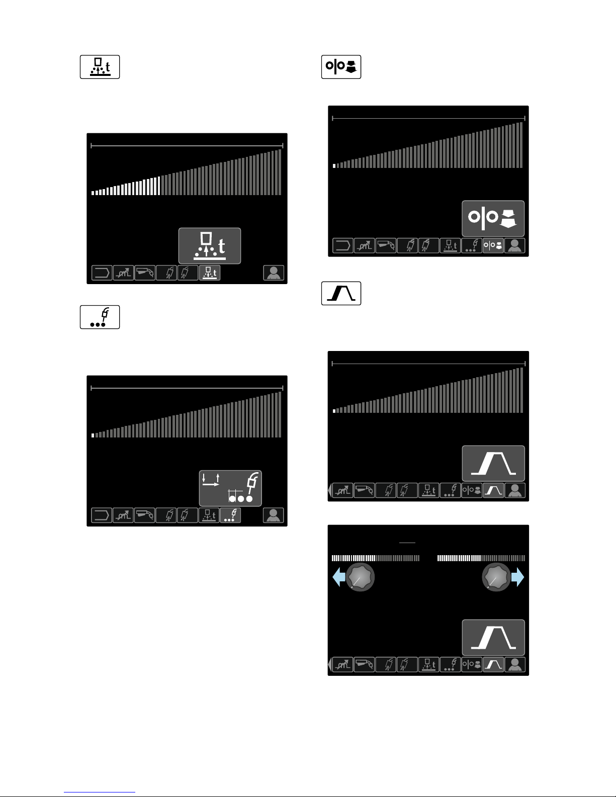
Preflow Time adjusts the time that shielding
gas flows after the trigger is pulled and prior
to feeding.
•••• Factory default, Preflow Time is set at 0.2 seconds.
•••• Adjust range: from 0 seconds (OFF) to 25 seconds.
M
OFF
25.0
M
0.2s
t1
t1
Figure 18.
Postflow Time adjusts the time that
shielding gas flows after the welding output
turns off.
•••• Factory default, Postflow Time is set at 2.5 second.
•••• Adjust range: from 0 seconds (OFF) to 25 seconds.
OFF 25.0
t2t1
t2
1.0s
Figure 19.
t2
t1
English English
14
Burnback Time is the amount of time that
the weld output continues after the wire
stops feeding. It prevents the wire from
sticking in the puddle and prepares the end of the wire
for the next arc start.
•••• Factory default, Burnback Time is set at 0.07
seconds.
•••• Adjust range: from OFF to 0.25 seconds.
OFF 0.25
M
t2t1
0.07s
Figure 20.
Spot Timer – adjusts the time welding will
continue even if the trigger is still pulled.
This option has no effect in 4-Step Trigger
Mode.
•••• Factory default, Spot Timer is OFF.
•••• Adjust range: from 0 second (OFF) to 120 seconds.
Note: Spot Timer has no effect in 4-Step Trigger Mode.
OFF 120
t2t1
OFF
t
Figure 21.
Run-in WFS – sets the wire feed speed
from the time the trigger is pulled until an arc
is established.
•••• Factory default, Run-in is turned off.
•••• Adjust range: from minimum to maximum WFS.
OFF 17.78
OFF
M
t1 t2
Figure 22.
The Start Procedure controls the WFS and
Volts (or Trim) for a specified time at the
beginning of the weld. During the start time,
the machine will ramp up or down from the Start
Procedure to the preset Welding Procedure.
•••• Adjust time range: from 0 seconds(OFF) to
10 seconds.
OFF 10.0
OFF
M
t1 t2
Figure 23.
1.0s
M
t1 t2
min
m
10.00
v
31.6
Figure 24.
 Loading...