

Page 1

GUARDIAN CONTROL™SOLUTIONS
RETURN TO MAIN MENU
IM10127
May, 2012
For use with machines having Code Numbers:
Safety Depends on You
Lincoln arc welding and cutting
equipment is designed and built
with safety in mind. However,
your overall safety can be
increased by proper installation
... and thoughtful operation on
your part. DO NOT INSTALL,
OPERATE OR REPAIR THIS
EQUIPMENT WITHOUT READING THIS MANUAL AND THE
SAFETY PRECAUTIONS CONTAINED THROUGHOUT. And,
most importantly, think before
you act and be careful.
JFS-C1, Guardian™ Panel
Cleveland, Ohio 44117-1199 U.S.A. TEL: 888.935.3878 FAX: 216.383.8823 WEB SITE: www.lincolnelectric.com
INSTRUCTION MANUAL
Copyright © Lincoln Global Inc.
• World's Leader in Welding and Cutting Products •
• Sales and Service through Subsidiaries and Distributors Worldwide •
Page 2

i
SAFETY
i
WARNING
CALIFORNIA PROPOSITION 65 WARNINGS
Diesel engine exhaust and some of its constituents
are known to the State of California to cause cancer, birth defects, and other reproductive harm.
The Above For Diesel Engines
ARC WELDING CAN BE HAZARDOUS. PROTECT YOURSELF AND OTHERS FROM POSSIBLE SERIOUS INJURY OR DEATH.
KEEP CHILDREN AWAY. PACEMAKER WEARERS SHOULD CONSULT WITH THEIR DOCTOR BEFORE OPERATING.
Read and understand the following safety highlights. For additional safety information, it is strongly recommended that you
purchase a copy of “Safety in Welding & Cutting - ANSI Standard Z49.1” from the American Welding Society, P.O. Box
351040, Miami, Florida 33135 or CSA Standard W117.2-1974. A Free copy of “Arc Welding Safety” booklet E205 is available
from the Lincoln Electric Company, 22801 St. Clair Avenue, Cleveland, Ohio 44117-1199.
BE SURE THAT ALL INSTALLATION, OPERATION, MAINTENANCE AND REPAIR PROCEDURES ARE
PERFORMED ONLY BY QUALIFIED INDIVIDUALS.
The engine exhaust from this product contains
chemicals known to the State of California to cause
cancer, birth defects, or other reproductive harm.
The Above For Gasoline Engines
FOR ENGINE
powered equipment.
1.a. Turn the engine off before troubleshooting and maintenance
work unless the maintenance work requires it to be running.
____________________________________________________
1.b. Operate engines in open, well-ventilated
areas or vent the engine exhaust fumes
outdoors.
____________________________________________________
1.c. Do not add the fuel near an open flame welding arc or when the engine is running. Stop
the engine and allow it to cool before refueling to prevent spilled fuel from vaporizing on
contact with hot engine parts and igniting. Do
not spill fuel when filling tank. If fuel is spilled,
wipe it up and do not start engine until fumes
have been eliminated.
____________________________________________________
1.d. Keep all equipment safety guards, covers and devices in position and in good repair.Keep hands, hair, clothing and tools
away from V-belts, gears, fans and all other moving parts
when starting, operating or repairing equipment.
____________________________________________________
1.e. In some cases it may be necessary to remove safety
guards to perform required maintenance. Remove
guards only when necessary and replace them when the
maintenance requiring their removal is complete.
Always use the greatest care when working near moving
parts.
___________________________________________________
1.f. Do not put your hands near the engine fan.
Do not attempt to override the governor or
idler by pushing on the throttle control rods
while the engine is running.
1.h. To avoid scalding, do not remove the
radiator pressure cap when the engine is
hot.
ELECTRIC AND
MAGNETIC FIELDS
may be dangerous
2.a. Electric current flowing through any conductor causes
localized Electric and Magnetic Fields (EMF). Welding
current creates EMF fields around welding cables and
welding machines
2.b. EMF fields may interfere with some pacemakers, and
welders having a pacemaker should consult their physician
before welding.
2.c. Exposure to EMF fields in welding may have other health
effects which are now not known.
2.d. All welders should use the following procedures in order to
minimize exposure to EMF fields from the welding circuit:
2.d.1.
Route the electrode and work cables together - Secure
them with tape when possible.
2.d.2. Never coil the electrode lead around your body.
2.d.3. Do not place your body between the electrode and
work cables. If the electrode cable is on your right
side, the work cable should also be on your right side.
___________________________________________________
1.g. To prevent accidentally starting gasoline engines while
turning the engine or welding generator during maintenance
work, disconnect the spark plug wires, distributor cap or
magneto wire as appropriate.
2.d.4. Connect the work cable to the workpiece as close as
possible to the area being welded.
2.d.5. Do not work next to welding power source.
Page 3
ii
SAFETY
ii
ELECTRIC SHOCK can kill.
3.a. The electrode and work (or ground) circuits
are electrically “hot” when the welder is on.
Do not touch these “hot” parts with your bare
skin or wet clothing. Wear dry, hole-free
gloves to insulate hands.
3.b. Insulate yourself from work and ground using dry insulation.
Make certain the insulation is large enough to cover your full
area of physical contact with work and ground.
In addition to the normal safety precautions, if welding
must be performed under electrically hazardous
conditions (in damp locations or while wearing wet
clothing; on metal structures such as floors, gratings or
scaffolds; when in cramped positions such as sitting,
kneeling or lying, if there is a high risk of unavoidable or
accidental contact with the workpiece or ground) use
the following equipment:
• Semiautomatic DC Constant Voltage (Wire) Welder.
• DC Manual (Stick) Welder.
• AC Welder with Reduced Voltage Control.
3.c. In semiautomatic or automatic wire welding, the electrode,
electrode reel, welding head, nozzle or semiautomatic
welding gun are also electrically “hot”.
3.d. Always be sure the work cable makes a good electrical
connection with the metal being welded. The connection
should be as close as possible to the area being welded.
3.e. Ground the work or metal to be welded to a good electrical
(earth) ground.
3.f.
Maintain the electrode holder, work clamp, welding cable and
welding machine in good, safe operating condition. Replace
damaged insulation.
3.g. Never dip the electrode in water for cooling.
3.h. Never simultaneously touch electrically “hot” parts of
electrode holders connected to two welders because voltage
between the two can be the total of the open circuit voltage
of both welders.
3.i. When working above floor level, use a safety belt to protect
yourself from a fall should you get a shock.
3.j. Also see Items 6.c. and 8.
ARC RAYS can burn.
4.a. Use a shield with the proper filter and cover
plates to protect your eyes from sparks and
the rays of the arc when welding or observing
open arc welding. Headshield and filter lens
should conform to ANSI Z87. I standards.
4.b. Use suitable clothing made from durable flame-resistant
material to protect your skin and that of your helpers from
the arc rays.
4.c. Protect other nearby personnel with suitable, non-flammable
screening and/or warn them not to watch the arc nor expose
themselves to the arc rays or to hot spatter or metal.
FUMES AND GASES
can be dangerous.
5.a. Welding may produce fumes and gases
hazardous to health. Avoid breathing these
fumes and gases. When welding, keep
your head out of the fume. Use enough
ventilation and/or exhaust at the arc to keep
fumes and gases away from the breathing zone. When
welding with electrodes which require special
ventilation such as stainless or hard facing (see
instructions on container or MSDS) or on lead or
cadmium plated steel and other metals or coatings
which produce highly toxic fumes, keep exposure as
low as possible and within applicable OSHA PEL and
ACGIH TLV limits using local exhaust or mechanical ventilation. In confined spaces or in some circumstances,
outdoors, a respirator may be required. Additional precautions are also required when welding on galvanized
steel.
5.b. The operation of welding fume control equipment is affected
by various factors including proper use and positioning of the
equipment, maintenance of the equipment and the specific
welding procedure and application involved. Worker exposure level should be checked upon installation and periodically thereafter to be certain it is within applicable OSHA PEL
and ACGIH TLV limits.
5.c.
Do not weld in locations near chlorinated hydrocarbon
coming from degreasing, cleaning or spraying operations.
The heat and rays of the arc can react with solvent vapors
form phosgene, a highly toxic gas, and other irritating products.
vapors
to
5.d. Shielding gases used for arc welding can displace air and
cause injury or death. Always use enough ventilation,
especially in confined areas, to insure breathing air is safe.
5.e. Read and understand the manufacturerʼs instructions for this
equipment and the consumables to be used, including the
material safety data sheet (MSDS) and follow your
employerʼs safety practices. MSDS forms are available from
your welding distributor or from the manufacturer.
5.f. Also see item 1.b.
Page 4
iii
SAFETY
iii
WELDING and CUTTING
SPARKS can
cause fire or explosion.
6.a.
Remove fire hazards from the welding area.
If this is not possible, cover them to prevent
Remember that welding sparks and hot materials from
welding can easily go through small cracks and openings to
adjacent areas. Avoid welding near hydraulic lines. Have a
fire extinguisher readily available.
6.b. Where compressed gases are to be used at the job site,
special precautions should be used to prevent hazardous
situations. Refer to “Safety in Welding and Cutting” (ANSI
Standard Z49.1) and the operating information for the
equipment being used.
6.c. When not welding, make certain no part of the electrode
circuit is touching the work or ground. Accidental contact can
cause overheating and create a fire hazard.
6.d. Do not heat, cut or weld tanks, drums or containers until the
proper steps have been taken to insure that such procedures
will not cause flammable or toxic vapors from substances
inside. They can cause an explosion even
been “cleaned”. For information, purchase “Recommended
Safe Practices for the
Containers and Piping That Have Held Hazardous
Substances”, AWS F4.1 from the American Welding Society
(see address above).
6.e. Vent hollow castings or containers before heating, cutting or
welding. They may explode.
Sparks and spatter are thrown from the welding arc. Wear oil
6.f.
free protective garments such as leather gloves, heavy shirt,
cuffless trousers, high shoes and a cap over your hair. Wear
ear plugs when welding out of position or in confined places.
Always wear safety glasses with side shields when in a
welding area.
6.g. Connect the work cable to the work as close to the welding
area as practical. Work cables connected to the building
framework or other locations away from the welding area
increase the possibility of the welding current passing
through lifting chains, crane cables or other alternate circuits.
This can create fire hazards or overheat lifting chains or
cables until they fail.
6.h. Also see item 1.c.
the welding sparks from starting a fire.
though
they have
Preparation
for Welding and Cutting of
CYLINDER may explode
if damaged.
7.a. Use only compressed gas cylinders
containing the correct shielding gas for the
process used and properly operating
regulators designed for the gas and
pressure used. All hoses, fittings, etc. should be suitable for
the application and maintained in good condition.
7.b. Always keep cylinders in an upright position securely
chained to an undercarriage or fixed support.
7.c. Cylinders should be located:
• Away from areas where they may be struck or subjected to
physical damage.
• A safe distance from arc welding or cutting operations and
any other source of heat, sparks, or flame.
7.d. Never allow the electrode, electrode holder or any other
electrically “hot” parts to touch a cylinder.
7.e. Keep your head and face away from the cylinder valve outlet
when opening the cylinder valve.
7.f. Valve protection caps should always be in place and hand
tight except when the cylinder is in use or connected for
use.
7.g. Read and follow the instructions on compressed gas
cylinders, associated equipment, and CGA publication P-l,
“Precautions for Safe Handling of Compressed Gases in
Cylinders,” available from the Compressed Gas Association
1235 Jefferson Davis Highway, Arlington, VA 22202.
FOR ELECTRICALLY
powered equipment.
8.a. Turn off input power using the disconnect
switch at the fuse box before working on
the equipment.
8.b. Install equipment in accordance with the U.S. National
Electrical Code, all local codes and the manufacturerʼs
recommendations.
8.c. Ground the equipment in accordance with the U.S. National
Electrical Code and the manufacturerʼs recommendations.
6.I. Read and follow NFPA 51B “ Standard for Fire Prevention
During Welding, Cutting and Other Hot Work”, available from
NFPA, 1 Batterymarch Park, PO box 9101, Quincy, Ma
022690-9101.
6.j. Do not use a welding power source for pipe thawing.
Refer to http://www.lincolnelectric.com/safety for additional safety information.
Page 5

iv
SAFETY
iv
PRÉCAUTIONS DE SÛRETÉ
Pour votre propre protection lire et observer toutes les instructions
et les précautions de sûreté specifiques qui parraissent dans ce
manuel aussi bien que les précautions de sûreté générales suivantes:
Sûreté Pour Soudage A LʼArc
1. Protegez-vous contre la secousse électrique:
a. Les circuits à lʼélectrode et à la piéce sont sous tension
quand la machine à souder est en marche. Eviter toujours
tout contact entre les parties sous tension et la peau nue
ou les vétements mouillés. Porter des gants secs et sans
trous pour isoler les mains.
b. Faire trés attention de bien sʼisoler de la masse quand on
soude dans des endroits humides, ou sur un plancher metallique ou des grilles metalliques, principalement dans
les positions assis ou couché pour lesquelles une grande
partie du corps peut être en contact avec la masse.
c. Maintenir le porte-électrode, la pince de masse, le câble de
soudage et la machine à souder en bon et sûr état defonctionnement.
d.Ne jamais plonger le porte-électrode dans lʼeau pour le
refroidir.
e. Ne jamais toucher simultanément les parties sous tension
des porte-électrodes connectés à deux machines à souder
parce que la tension entre les deux pinces peut être le total
de la tension à vide des deux machines.
f. Si on utilise la machine à souder comme une source de
courant pour soudage semi-automatique, ces precautions
pour le porte-électrode sʼapplicuent aussi au pistolet de
soudage.
2. Dans le cas de travail au dessus du niveau du sol, se protéger
contre les chutes dans le cas ou on recoit un choc. Ne jamais
enrouler le câble-électrode autour de nʼimporte quelle partie du
corps.
5. Toujours porter des lunettes de sécurité dans la zone de
soudage. Utiliser des lunettes avec écrans lateraux dans les
zones où lʼon pique le laitier.
6. Eloigner les matériaux inflammables ou les recouvrir afin de
prévenir tout risque dʼincendie dû aux étincelles.
7. Quand on ne soude pas, poser la pince à une endroit isolé de
la masse. Un court-circuit accidental peut provoquer un
échauffement et un risque dʼincendie.
8. Sʼassurer que la masse est connectée le plus prés possible de
la zone de travail quʼil est pratique de le faire. Si on place la
masse sur la charpente de la construction ou dʼautres endroits
éloignés de la zone de travail, on augmente le risque de voir
passer le courant de soudage par les chaines de levage,
câbles de grue, ou autres circuits. Cela peut provoquer des
risques dʼincendie ou dʼechauffement des chaines et des
câbles jusquʼà ce quʼils se rompent.
9. Assurer une ventilation suffisante dans la zone de soudage.
Ceci est particuliérement important pour le soudage de tôles
galvanisées plombées, ou cadmiées ou tout autre métal qui
produit des fumeés toxiques.
10. Ne pas souder en présence de vapeurs de chlore provenant
dʼopérations de dégraissage, nettoyage ou pistolage. La
chaleur ou les rayons de lʼarc peuvent réagir avec les vapeurs
du solvant pour produire du phosgéne (gas fortement toxique)
ou autres produits irritants.
11. Pour obtenir de plus amples renseignements sur la sûreté, voir
le code “Code for safety in welding and cutting” CSA Standard
W 117.2-1974.
PRÉCAUTIONS DE SÛRETÉ POUR
3. Un coup dʼarc peut être plus sévère quʼun coup de soliel, donc:
a. Utiliser un bon masque avec un verre filtrant approprié ainsi
quʼun verre blanc afin de se protéger les yeux du rayonnement de lʼarc et des projections quand on soude ou
quand on regarde lʼarc.
b. Porter des vêtements convenables afin de protéger la peau
de soudeur et des aides contre le rayonnement de lʻarc.
c. Protéger lʼautre personnel travaillant à proximité au
soudage à lʼaide dʼécrans appropriés et non-inflammables.
4. Des gouttes de laitier en fusion sont émises de lʼarc de
soudage. Se protéger avec des vêtements de protection libres
de lʼhuile, tels que les gants en cuir, chemise épaisse, pantalons sans revers, et chaussures montantes.
LES MACHINES À SOUDER À
TRANSFORMATEUR ET À
REDRESSEUR
1. Relier à la terre le chassis du poste conformement au code de
lʼélectricité et aux recommendations du fabricant. Le dispositif
de montage ou la piece à souder doit être branché à une
bonne mise à la terre.
2. Autant que possible, Iʼinstallation et lʼentretien du poste seront
effectués par un électricien qualifié.
3. Avant de faires des travaux à lʼinterieur de poste, la debrancher à lʼinterrupteur à la boite de fusibles.
4. Garder tous les couvercles et dispositifs de sûreté à leur place.
Page 6

Thank You
vv
for selecting a QUALITY product by Lincoln Electric. We want you
to take pride in operating this Lincoln Electric Company product •••
as much pride as we have in bringing this product to you!
The business of The Lincoln Electric Company is manufacturing and selling high quality welding equipment, consumables, and cutting equipment. Our challenge is to meet the needs of our customers and to exceed their expectations. On occasion, purchasers may ask Lincoln Electric
for advice or information about their use of our products. We respond to our customers based on the best information in our possession at that
time. Lincoln Electric is not in a position to warrant or guarantee such advice, and assumes no liability, with respect to such information or
advice. We expressly disclaim any warranty of any kind, including any warranty of fitness for any customerʼs particular purpose, with respect
to such information or advice. As a matter of practical consideration, we also cannot assume any responsibility for updating or correcting any
such information or advice once it has been given, nor does the provision of information or advice create, expand or alter any warranty with
respect to the sale of our products.
Lincoln Electric is a responsive manufacturer, but the selection and use of specific products sold by Lincoln Electric is solely within the control
of, and remains the sole responsibility of the customer. Many variables beyond the control of Lincoln Electric affect the results obtained in
applying these types of fabrication methods and service requirements.
Subject to Change – This information is accurate to the best of our knowledge at the time of printing. Please refer to www.lincolnelectric.com
for any updated information.
CUSTOMER ASSISTANCE POLICY
Please Examine Carton and Equipment For Damage Immediately
When this equipment is shipped, title passes to the purchaser upon receipt by the carrier. Consequently, Claims
for material damaged in shipment must be made by the purchaser against the transportation company at the time
the shipment is received.
Please record your equipment identification information below for future reference. This information can be found
on your machine nameplate.
Product _________________________________________________________________________________
Model Number ___________________________________________________________________________
Code Number or Date Code_________________________________________________________________
Serial Number____________________________________________________________________________
Date Purchased___________________________________________________________________________
Where Purchased_________________________________________________________________________
Whenever you request replacement parts or information on this equipment, always supply the information you
have recorded above. The code number is especially important when identifying the correct replacement parts.
On-Line Product Registration
- Register your machine with Lincoln Electric either via fax or over the Internet.
• For faxing: Complete the form on the back of the warranty statement included in the literature packet
accompanying this machine and fax the form per the instructions printed on it.
• For On-Line Registration: Go to our
Your Product”. Please complete the form and submit your registration.
Read this Operators Manual completely before attempting to use this equipment. Save this manual and keep it
handy for quick reference. Pay particular attention to the safety instructions we have provided for your protection.
The level of seriousness to be applied to each is explained below:
WEB SITE at www.lincolnelectric.com. Choose “Support” and then “Register
WARNING
This statement appears where the information must be followed exactly to avoid serious personal injury or loss of life.
CAUTION
This statement appears where the information must be followed to avoid minor personal injury or damage to this equipment.
Page 7

TABLE OF CONTENTS
Page
Installation.......................................................................................................................Section A
Technical Specifications ..............................................................................................A-1/A-11
General Description............................................................................................................A-12
Product Combinations ........................................................................................................A-12
Safety Precautions .............................................................................................................A-14
Typical Installation Sequence ............................................................................................A-14
Tools And Requirements....................................................................................................A-14
Installation And Commissioning ................................................................................A-14/A-40
Filter/Fan .....................................................................................................................A-14
Spark Guardian™...............................................................................................A-15/A-18
Sliding Valves .....................................................................................................A-19/A-21
Solenoid Valve....................................................................................................A-22/A-23
Oil Guardian™ ............................................................................................................A-23
Flame Guardian™ ..............................................................................................A-24/A-27
Guardian™ Panel ...............................................................................................A-28/A-31
Heat Detector Set...............................................................................................A-32/A-33
Spark Detector Set .............................................................................................A-34/A-36
Smoke Detector Set ...........................................................................................A-37/A-40
Commissioning Checklist...........................................................................................A-41/A-43
Operation.........................................................................................................................Section B
Safety ...................................................................................................................................B-1
Intended Use ........................................................................................................................B-1
General Description..............................................................................................................B-2
Product Combinations ..........................................................................................................B-2
Component Descriptions ......................................................................................................B-2
Operation In Case Of Fire....................................................................................................B-4
Component Description and Operation .......................................................................B-5/B-10
Fire Action Procedure ........................................................................................................B-11
Oil Guardian Operation ......................................................................................................B-12
vivi
Accessories.....................................................................................................Section C
Options / Accessories............................................................................................C-1
Maintenance ....................................................................................................Section D
Safety Precautions ................................................................................................D-1
Periodic Maintenance............................................................................................D-1
General Instructions ..............................................................................................D-1
Maintenance Calender ..........................................................................................D-2
Aerosol Disposal ...................................................................................................D-3
Guardian™ Panel..................................................................................................D-3
Heat Detector Set..................................................................................................D-3
Spark Detector Set................................................................................................D-3
Smoke Detector Set ..............................................................................................D-4
Sliding Valves........................................................................................................D-4
Aerosol ..................................................................................................................D-4
Spark Guardian™..................................................................................................D-5
Disposal.................................................................................................................D-6
Oil Guardian Maintenance.....................................................................................D-6
Troubleshooting..............................................................................................Section E
How To Use Troubleshooting Guide .....................................................................E-1
Troubleshooting Guide....................................................................................E-2/E-3
Wiring Diagrams..............................................................................................Section F
Parts List.....................................................................................................P-709 Series
________________________________________________________________________
Page 8
A-1
INSTALLATION
FIRE PROTECTION
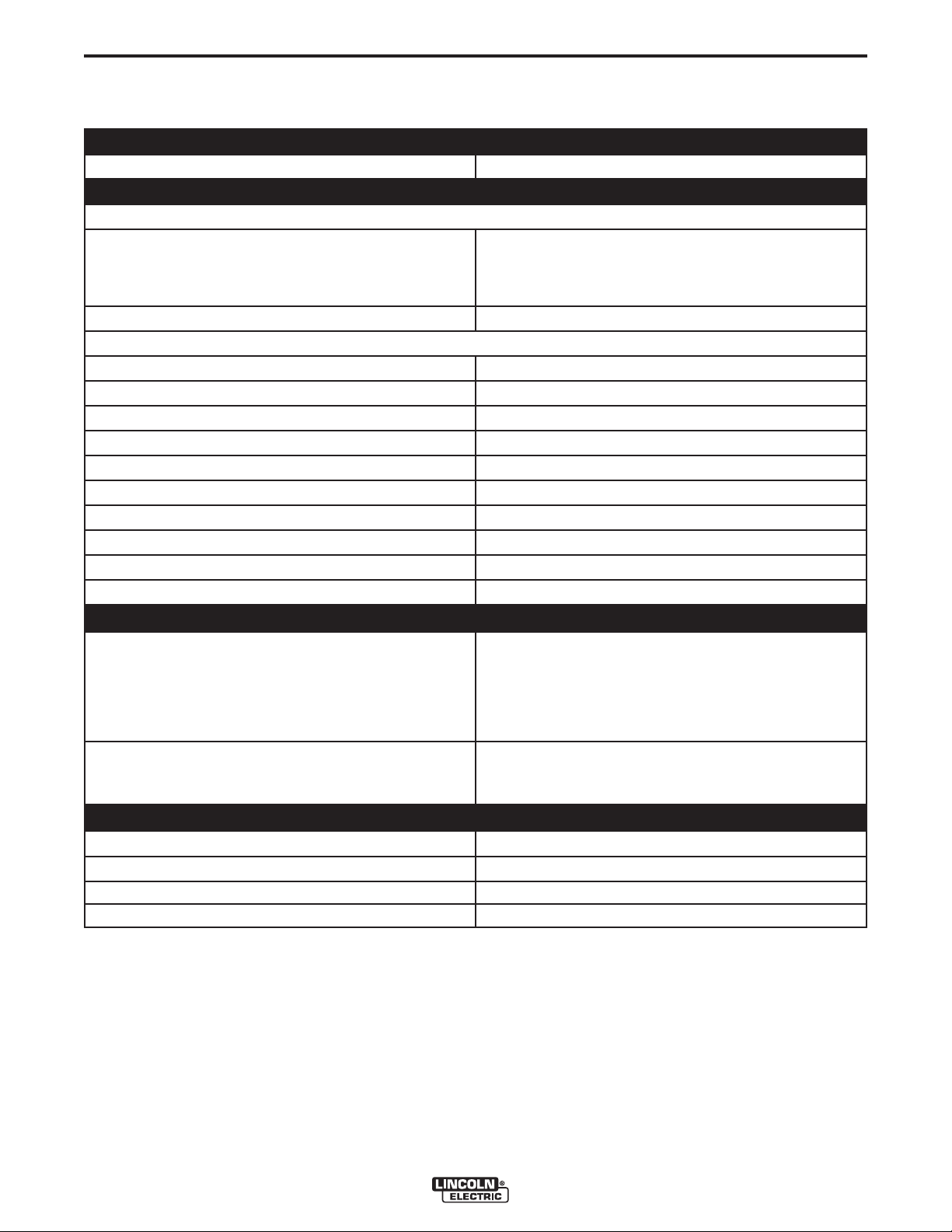
TECHNICAL SPECIFICATIONS - SPARK GUARDIAN™
MATERIAL
HOUSING (INLET + OUTLET) Powder-coated steel
CYCLONE Galvanized steel
DUSTBIN Tin
HOSE Spark resistant glassfibre/kevlar/metal
WEIGHT (excl. dustbin)
SPARK GUARDIAN™ - 250 44 lbs (20 kg)
SPARK GUARDIAN™ - 400 71 lbs (32 kg)
SPARK GUARDIAN™ - 500 110 lbs (50 kg)
SPARK GUARDIAN™ - 10 44 lbs (20 kg)
SPARK GUARDIAN™ - 16 71 lbs (32 kg)
SPARK GUARDIAN™ - 20 110 lbs (50 kg)
DUSTBIN OPTIONS
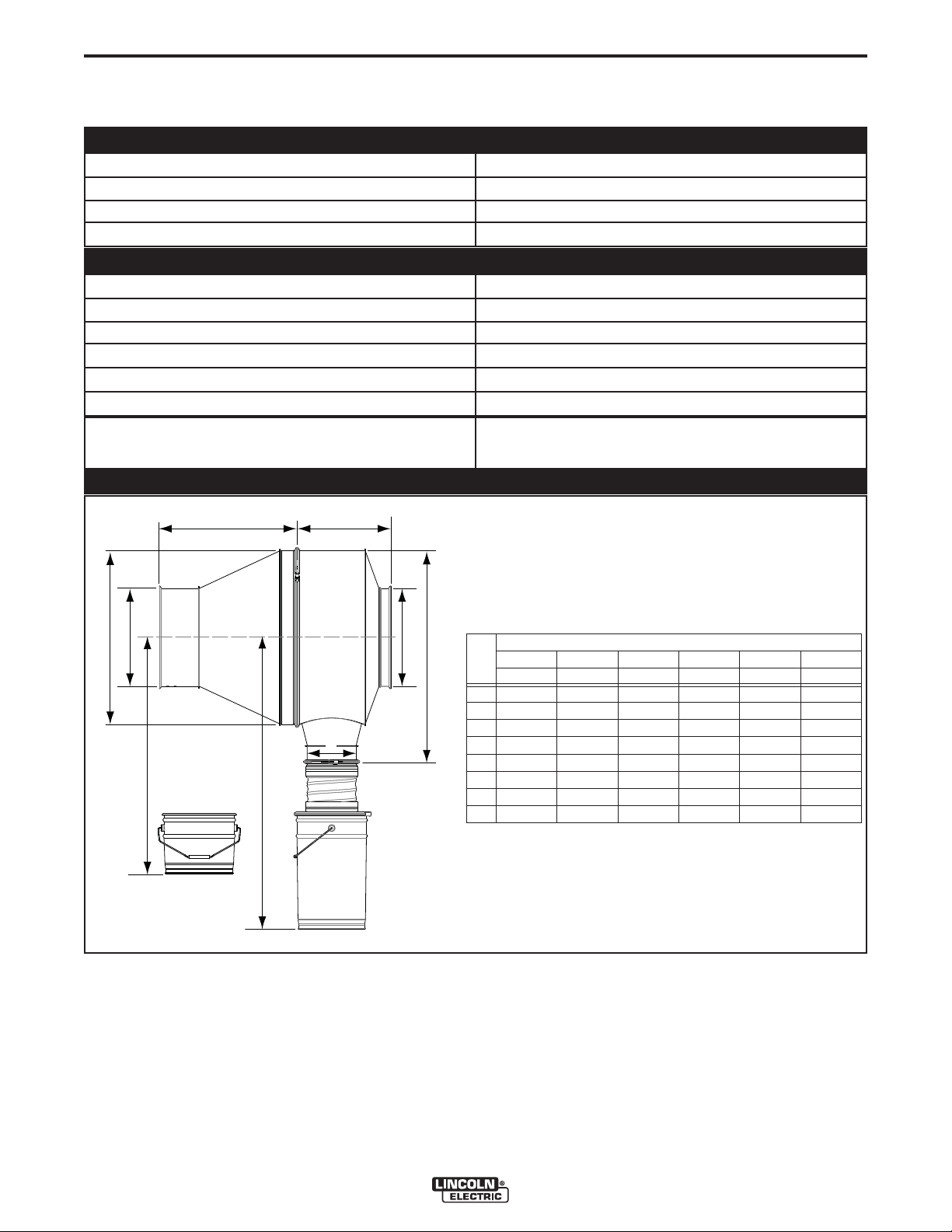
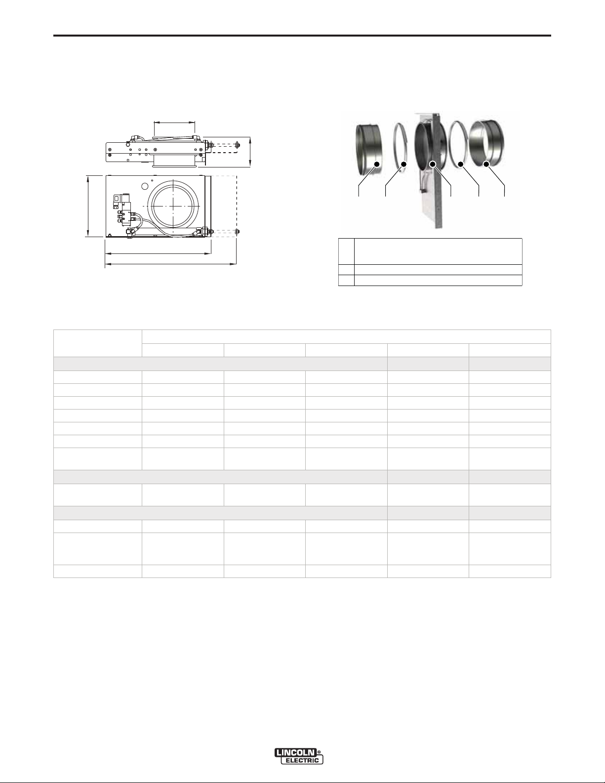
DIMENSIONS
A-1
+/- 0.5 CF (13 Liters)
+/- 1.0 CF (27 Liters)
GD
B
A
F
C
E
BH
SparkShield-
250 10 400 16 500 20
mm inch mm inch mm inch
A Ø 500 Ø 19.7 Ø 710 Ø 28.0 Ø 900 Ø 35.4
B Ø 250 Ø 9.8 Ø 400 Ø 15.7 Ø 500 Ø 19.7
C min. 825 min. 32.5 min. 970 min. 38.2 min. 1095 min. 43.1
D 433 17.0 558 23.1 654 25.7
E min. 1050 min. 41.3 min. 1200 min. 47.2 min. 1325 min. 52.2
F Ø 200 Ø 7.9 Ø 200 Ø 7.9 Ø 200 Ø 7.9
G 345 13.6 385 15.2 505 19.9
H 616 24.3 866 34.1 1086 42.8
GUARDIAN CONTROL™ SOLUTIONS
Page 9
A-2
INSTALLATION
FIRE PROTECTION
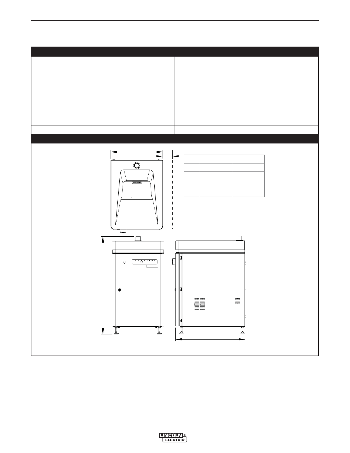
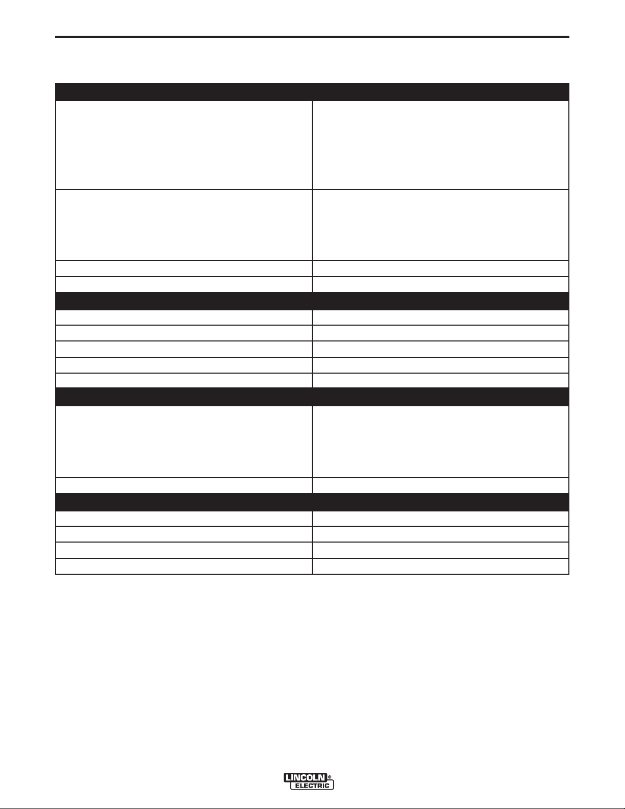
TECHNICAL SPECIFICATIONS - OIL GUARDIAN™
PHYSICAL DIMENSIONS AND PROPERTIES
MATERIAL HOUSING Steel
COLOR:
A-2
HOUSING
TOP COVER
WEIGHT (NET; WITHOUT LIMESTONE) 379 lbs. (172 kg)
CONTENTS LIMESTONE RESERVOIR 18.5 gallons / 70 liters (equal to 165 lbs / 75 kgs of
LIMESTONE ALARM LEVEL <55 lbs. (25 kg); add 110 lbs. (50 kg)
LIMESTONE QUALITY Calcium carbonate OmyaCarb®15 GU or equivalent
(not included; to be sourced locally)
LIMESTONE CONSUMPTION
MDB-4
MDB-24
PROTECTION CLASS CONTROL BOX in accordance with:
DISTANCE TO MAIN DUCT Maximum 50 ft (15 m)
REQUIRED AIRFLOW IN DUCT Minimum 25 ft/s (7.5 m/s)
10-20 g per filter cartridge per hour; e.g.:
Grey RAL 7011
Grey RAL 7035
limestone
40-80 g/h
240-480 g/h
IEC 60204
UL 508A
ELECTRICAL DATA
CONNECTION VOLTAGE 400V/3ph/50Hz
480V/3ph/60Hz
600V/3ph/50Hz
MOTOR POWER:
UPPER (AGITATOR)
MIDDLE (AGITATOR)
LOWER (SCREW CONVEYOR)
250 W (0.33 HP)
375 W (0.5 HP)
90 W (0.1 HP)
AMBIENT CONDITIONS
OPERATING TEMPERATURE:
NORMAL
MINIMUM
MAXIMUM
MAXIMUM RELATIVE HUMIDITY 80%
OUTDOOR USE ALLOWED no
STORAGE CONDITIONS 41-113º F (5-45ºC)
Relative humidity maximum 80%
41º (5ºC)
68º (20ºC)
113º (45ºC)
OPTIONS AND ACCESSORIES
EXTERNAL LIGHT POWER For wall mounting
GUARDIAN CONTROL™ SOLUTIONS
Page 10
A-3
INSTALLATION
FIRE PROTECTION
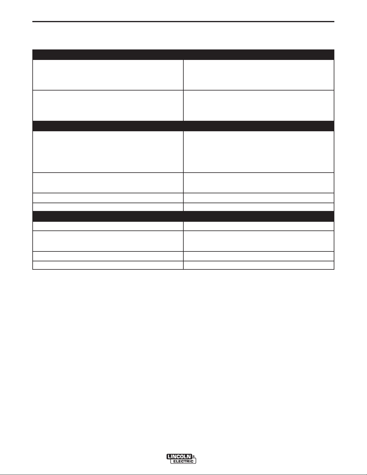
TECHNICAL SPECIFICATIONS - OIL GUARDIAN™
SHIPPING DATA
GROSS WEIGHT:
A-3
EXCLUDING PALLET
INCLUDING PALLET
PACKING DIMENSIONS:
BOX
2 BOXES ON 1 PALLET
HARMONIZED TARIFF CODE
COUNTRY OF ORIGIN Netherlands
24.4 x 31.5 x 43.7 in. (620 x 800 x 1110 mm)
47.2 x 31.5 x 48.4 in. (1200 x 800 x 1230 mm)
392 lbs (178 kg)
439 lbs (199 kg)
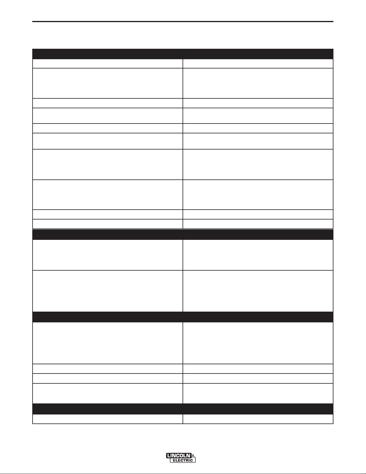
DIMENSIONS
A
B
mm inch
A 560 22.0
B* 660 26.0
C 1055 41.5
D 750 29.5
C
* Open door
D
GUARDIAN CONTROL™ SOLUTIONS
Page 11
A-4
INSTALLATION
FIRE DETECTION
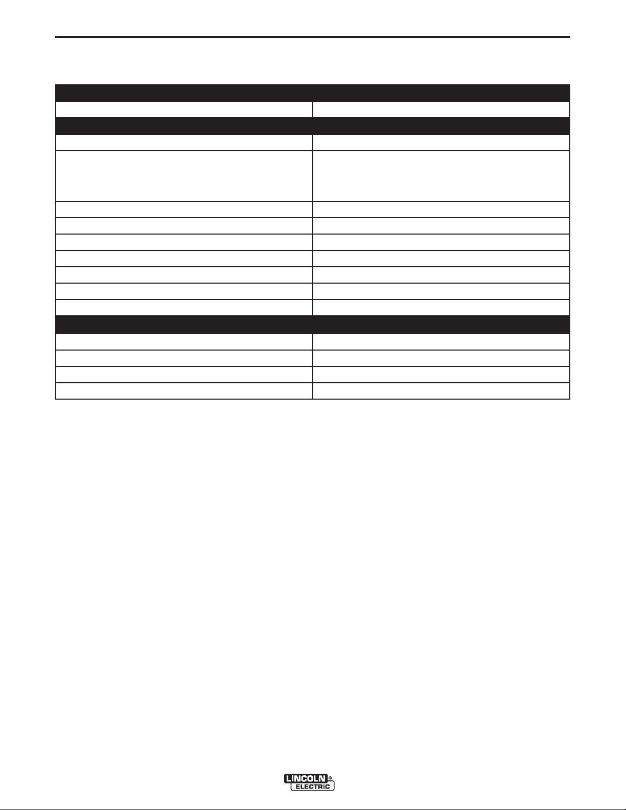
TECHNICAL SPECIFICATIONS - SMOKE DETECTOR
PHYSICAL DIMENSIONS AND PROPERTIES
HOUSING:
A-4
DIMENSIONS L X W X H
MATERIAL
COLOR
SCREW CONNECTIONS
AIR SAMPLING TUBE:
STANDARD LENGTH
MINIMUM LENGTH
MATERIAL
SENSOR TYPE Scattering RM 3.3 (ALK-E)
WEIGHT (NET) 5.5 lbs (2.5 kg)
10.1 x 6.5 x 3.0 in. (257 x 166 x 77 mm)
ABS
Yellow + red
3x M16
23.6 in. (600 mm)
6.3 in. (160 mm)
Aluminum with plastic end cap
TECHNICAL DATA
OPERATING VOLTAGE 24 V AC/DC +15%/-10%
RATED CURRENT 120 mA
RELAY OUTPUTS Floating
ALARM RELAY LOCKED 24 C DC
PROTECTION CLASS IP 54
AMBIENT CONDITIONS
OPERATING TEMPERATURE:
MINIMUM
NOMINAL
MAXIMUM
RELATIVE HUMIDITY 10-95% non-condensing
14º F (-10ºC)
68º F (+20ºC)
122º F (+50ºC)
SHIPPING DATA
GROSS WEIGHT 6.6 lbs. (3 kg)
PACKING DIMENSIONS 23.6 x 9.4 x 7.9 in. (660 x 240 x 200 mm)
HARMONIZED TARIFF CODE 9027.8099.00
COUNTRY OF ORIGIN Germany
GUARDIAN CONTROL™ SOLUTIONS
Page 12
A-5
INSTALLATION
FIRE DETECTION
TECHNICAL SPECIFICATIONS - HEAT DETECTOR SET
PHYSICAL DIMENSIONS AND PROPERTIES
HOUSING:
A-5
DIMENSIONS L X W X H
MATERIAL
HEAT DETECTOR:
DIMENSIONS (INCLUDING THREADED ROD)
MATERIAL
TECHNICAL DATA
ELECTRICAL RATING 5.0 Amps 126 VAC
TEMPERATURE SETTING
TOLERANCE
ACTING TYPE NO (normally open)
PROTECTION CLASS IP 65
SHIPPING DATA
GROSS WEIGHT
PACKING DIMENSIONS 12.2 x 9.0 x 9.2 in. (309 x 229 x 234 mm)
3.1 x 3.0 x 2.2 in. (80 x 75 x 56 mm)
Aluminum
L = 4.5 in. (115 mm); ø 0.6 in. (15 mm)
Tube: high alloy steel; screw thread: brass
0.5 Amps 125 VDC
2.0 Amps 24 VDC
1.0 Amps 48 VDC
190º F (88ºC)
+7/-8ºF (+14º/-13ºC)
HARMONIZED TARIFF CODE 9031.8098.90
COUNTRY OF ORIGIN USA
GUARDIAN CONTROL™ SOLUTIONS
Page 13
A-6
INSTALLATION
FIRE DETECTION
TECHNICAL SPECIFICATIONS - SPARK DETECTOR SET
PHYSICAL DIMENSIONS AND PROPERTIES
MATERIAL HOUSING Aluminum (NEMA 4 rated)
TECHNICAL DATA
OPERATING VOLTAGE 22-28 V DC
CURRENT:
A-6
OPERATING
ALARM
SENSITIVITY 1 uW/cm
DETECTION Infrared and partial optical light spectrum
RESPONSE TIME 0.5 millisecond
DURATION OF RESPONSE 1 second - closing of potential-free contact
VIEW ANGLE 100%
SPECTRAL RESPONSE 0.4 - 1.1 microns wavelength
RESPONSE PEAK 0.9 microns
10 mA
40 mA
2
SHIPPING DATA
GROSS WEIGHT
PACKING DIMENSIONS 12.2 x 9.0 x 9.2 in. (309 x 229 x 234 mm)
HARMONIZED TARIFF CODE 9031.4990.00
COUNTRY OF ORIGIN Canada
GUARDIAN CONTROL™ SOLUTIONS
Page 14
A-7
INSTALLATION
FIRE SUPPRESSION
TECHNICAL SPECIFICATIONS - SLIDING VALVES
PHYSICAL DIMENSIONS AND PROPERTIES
MATERIAL HOUSING Galvanized Steel
TECHNICAL DATA
PNEUMATIC CYLINDER
PRESSURE:
A-7
NORMAL
MAXIMUM
COMPRESSED AIR QUALITY Dry and oil-free according to ISO 8573-3 class 6
SOLENOID VALVE
TYPE OF VALVE 5/2 solenoid valve with spring reset
ACTING TYPE NC (normally closed)
POWER SUPPLY 24 VAC
POWER CONSUMPTION 3 W
ELECTRICAL CONNECTION According to DIN 43650
POWER TOLERANCE +/- 10%
POWER REQUIREMENT Approx. 5 W
PROTECTION CLASS IP 65
INSULATION CLASS B
COMPRESSED AIR CONNECTION Quick release for ø 0.24 in. (6 mm) hose
58-73 psi (4-5 bar)
131 psi (9 bar)
AMBIENT CONDITIONS
OPERATING TEMPERATURE:
MINIMUM
NOMINAL
-4ºF (-20ºC)
68ºF (+20ºC)
MAXIMUM
OUTDOOR USE ALLOWED Yes (if housed in a weather-tight enclosure and com-
pressed air is not allowed to cool down below its dew
122ºF (+50ºC)
point)
SHIPPING DATA
GROSS WEIGHT See Table A.1
PACKING DIMENSIONS See Table A.1
HARMONIZED TARIFF CODE 8481.3091.90
COUNTRY OF ORIGIN Germany
GUARDIAN CONTROL™ SOLUTIONS
Page 15
A-8
INSTALLATION
FIRE SUPPRESSION
TECHNICAL SPECIFICATIONS - SLIDING VALVES
A-8
FIGURE – A.1
FIGURE – A.2
C
E
A
B
D
AB C BA
A Metric sizes: connection flange (metric to metric)•
Imperial sizes (shown): connection piece from •
metric (mm) to imperial (in.)
B Quick connect coupling
C Sliding valve
TABLE – A.1
SLIDING VALVE (metric sizes in brackets)
SV-10 (SV-250) SV-12 (SV-315) SV-16 (SV-400) SV-20 (SV-500) SV-24 (SV-630)
PHYSICAL DIMENSIONS AND PROPERTIES
A 14.6 in. (370 mm) 17.1 in. (435 mm) 20.5 in. (520 mm) 26.8 in. (680 mm) 30.7 in. (780 mm)
B 23.0 in. (585 mm) 28.7 in. (730 mm) 35.6 in. (905 mm) 42.7 in. (1085 mm) 52.8 in. (1340 mm)
C Ø 9.8 in. (250 mm) Ø 12.4 in. (315 mm) Ø 15.7 in. (400 mm) Ø 19.7 in. (500 mm) Ø 24.8 in. (630 mm)
D 33.3 in. (845 mm) 41.5 in. (1055 mm) 51.8 in. (1315 mm) 62.8 in. (1595 mm) 78.0 in. (1980 mm)
E 6.5 in. (165 mm) 6.5 in. (165 mm) 6.5 in. (165 mm) 9.8 in. (250 mm) 9.8 in. (250 mm)
Weight (net) 36 lbs (16 kg) 53 lbs (24 kg) 71 lbs (32 kg) 136 lbs (74 kg) 212 lbs (96 kg)
Appropriate duct
diameter
ORDER INFORMATION
Article number SV-250: 7900201000
SHIPPING DATA
Gross weight 40 lbs (18 kg) 57 lbs (26 kg) 77 lbs (35 kg) 172 lbs (78 kg) 223 lbs (101 kg)
Packing dimensions
(excl. pallet)
Max. no./pallet
Ø 10 in. (250 mm) Ø 12 in. (315 mm) Ø 16 in. (400 mm) Ø 20 in. (500 mm) Ø 24 in. (630 mm)
SV-10: 7900202000
31.5 x 23.6 x 15.7 in.
(800 x 600 x 400 mm)
SV-315: 7900201010
SV-12: 7900202010
31.5 x 23.6 x 15.7 in.
(800 x 600 x 400 mm)
SV-400: 7900201020
SV-16: 7900202020
31.5 x 47.2 x 19.7 in.
(800 x 1200 x 500
mm)
SV-500: 7900201030
SV-20: 7900202030
31.5 x 47.2 x 23.6 in.
(800 x 1200 x 600
mm)
SV-630: 7900201040
SV-24: 7900202040
31.5 x 47.2 x 41.3 in.
(800 x 1200 x 1050
mm)
GUARDIAN CONTROL™ SOLUTIONS
Page 16
A-9
INSTALLATION
FIRE SUPPRESSION
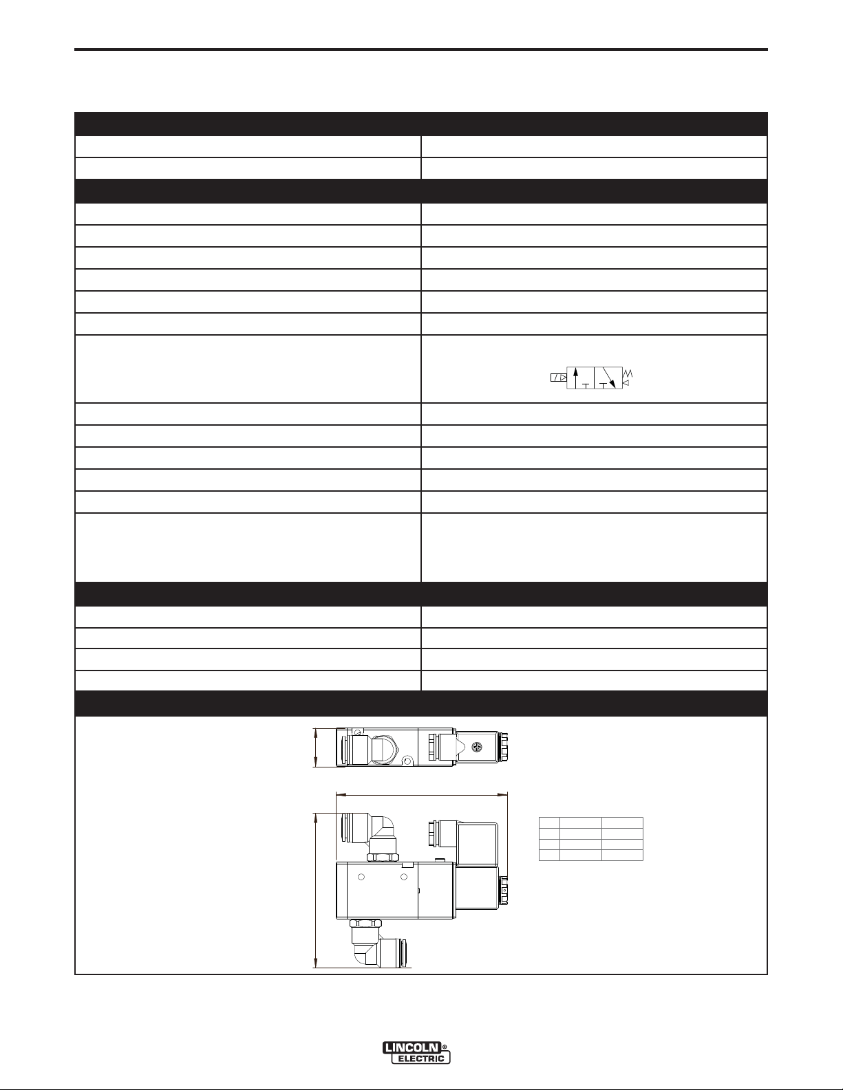
TECHNICAL SPECIFICATIONS - SOLENOID VALVE
PHYSICAL DIMENSIONS AND PROPERTIES
MATERIAL BODY Aluminum Alloy
DIMENSIONS See Below
TECHNICAL DATA
OPERATING VOLTAGE 24 V AC +/- 15%
POWER CONSUMPTION 3.5 W
PROTECTION CLASS IP 65
VALVE TYPE 3 ports, 2 positions
PORT SIZE 3/8 inch
THREAD TYPE G
ACTING TYPE NC (normally closed)
ELECTRICAL ENTRY TYPE Terminal
COMPRESSED AIR TUBE CONNECTION ø 12 mm
OPERATING PRESSURE 21-114 psi (0.15-0.8 mPa)
ACTIVATING TIME <0.05 seconds
FREQUENCY Maximum 5 cycles/second
OPERATING TEMPERATURE
A-9
A
PR
MINIMUM
MAXIMUM
-4º F (-20ºC)
158º F (+70ºC)
SHIPPING DATA
GROSS WEIGHT
PACKING DIMENSIONS 10.0 x 5.9 x 3.5 in. (255 x 150 x 90 mm)
HARMONIZED TARIFF CODE 8536.4110.90
COUNTRY OF ORIGIN
DIMENSIONS
A
C
mm inch
A 27 1.06
B 109 4.29
C 120 4.72
A
B
R
P
GUARDIAN CONTROL™ SOLUTIONS
Page 17

A-10
INSTALLATION
TECHNICAL SPECIFICATIONS - FLAME GUARDIAN™
PHYSICAL DIMENSIONS AND PROPERTIES
FLAME GUARDIAN 200 FLAME GUARDIAN 500
DIMENSIONS (excluding bracket)
Length = 7.3 in. (185mm)
A-10
Length = 11.5 in. (293mm)
WEIGHT (excluding bracket)
MATERIAL BRACKET
MASS OF EXTINGUISHING MATERIAL
ACTIVATION MODES
ACTIVATOR
TESTING CURRENT
OPERATION DISCHARGE TIME
DISCHARGE OUTLET
DISCHARGE LENGTH
FIRE CLASSES:
USA (NFPA 10)
EUROPE (EN-2)
SERVICE LIFE (installed)
SHELF LIFE
STORAGE CONDITIONS
ø 3.3 in. (84mm)
3.3 lbs. (1510 g) 5.9 lbs. (2670 g)
Sheet Metal Sheet Metal
0.44 lbs. (200 g) 1.1 lbs. (500 g)
• By fire detection panel
• Self-Activating at 572ºF (300ºC)
Heat element with 2.3Ω resistance
max. 5 mA max. 5 mA
5 - 10 Seconds 5 - 10 Seconds
1 1
6.6 ft. (2 m) 8.2 ft. (2.5 m)
A, B, C, K
A, B, C, F
10 years 10 years
15 years 15 years
ø 3.3 in (84mm)
A, B, C, K
A, B, C, F
TEMPERATURE
RELATIVE HUMIDITY
GROSS WEIGHT
PACKING DIMENSIONS
HARMONIZED TARIFF CODE
COUNTRY OF ORIGIN
Between -58º and +212ºF (-50º and +100ºC)
Maximum 98%
SHIPPING DATA
FLAME GUARDIAN 200 FLAME GUARDIAN 500
6.6 lbs. (3 kg) 8.8 lbs. (4 kg)
23.8 x 4.5 x 5.4 in. (604 x 114 x 138 mm)
8424.1000.90
EU
GUARDIAN CONTROL™ SOLUTIONS
Page 18

A-11
INSTALLATION
TECHNICAL SPECIFICATIONS - GUARDIAN CONTROL™ PANEL
BATTERY
8.0AH or 12.0AH Battery Standby
ZONES
(4) Input Zones (4) Output Zones
DISPLAY
2 line 32 character alpha numeric liquid crystal display shows the condition, status and circuit for Alarm,
Supervisory and trouble conditions.
INPUT POWER
120 VAC, 60 Hz (165VA) or 220 VAC, 50/60 Hz (185 VA)
AMBIENT CONDITIONS
Minimum Temperature: 23ºF (-5ºC)
Maximum Temperature: 104ºF (+40ºC)
Relative Humidity: 95%
TECHNICAL SPECIFICATIONS - SYSTEM CONTROL PANEL
A-11
INPUT
DESCRIPTION INPUT VOLTAGE +/- 10% NORMAL CURRENT (MAX.)
Air Handling 380-480V/3~/50-60HZ 13.9A
TEMPERATURE RANGE RELATIVE HUMIDITY
41ºF (5ºC) to 113ºF (45ºC) Maximum 80%
GUARDIAN CONTROL™ SOLUTIONS
Page 19

A-12
INSTALLATION
GENERAL DESCRIPTION
This manual describes installation and maintenance of
components for fire detection and suppression.
FIRE PREVENTION
• Spark Guardian™
• Oil Guardian™
FIRE DETECTION
• Heat Detectors (2)
• Spark Detectors (1 Set)
• Smoke Detector (1)
• Fire Detection Control Panel
FIRE SUPPRESSION
• Sliding Valves
• Solenoid Valve
• Aerosol Fire Extinguishing Generator
PRODUCT COMBINATIONS
The fire detection & suppression system is to be
installed with:
A-12
• Spark Guardian™ (cyclone spark arrester)
• Oil Guardian™ (lime feeder)
• Central filter system type (Statiflex filter bank), ranging from 4-bank to 48-bank (other sizes on request)
• Central fan
• System control panel (SCP)
• Round ductwork of the appropriate diameter
GUARDIAN CONTROL™ SOLUTIONS
Page 20
A-13
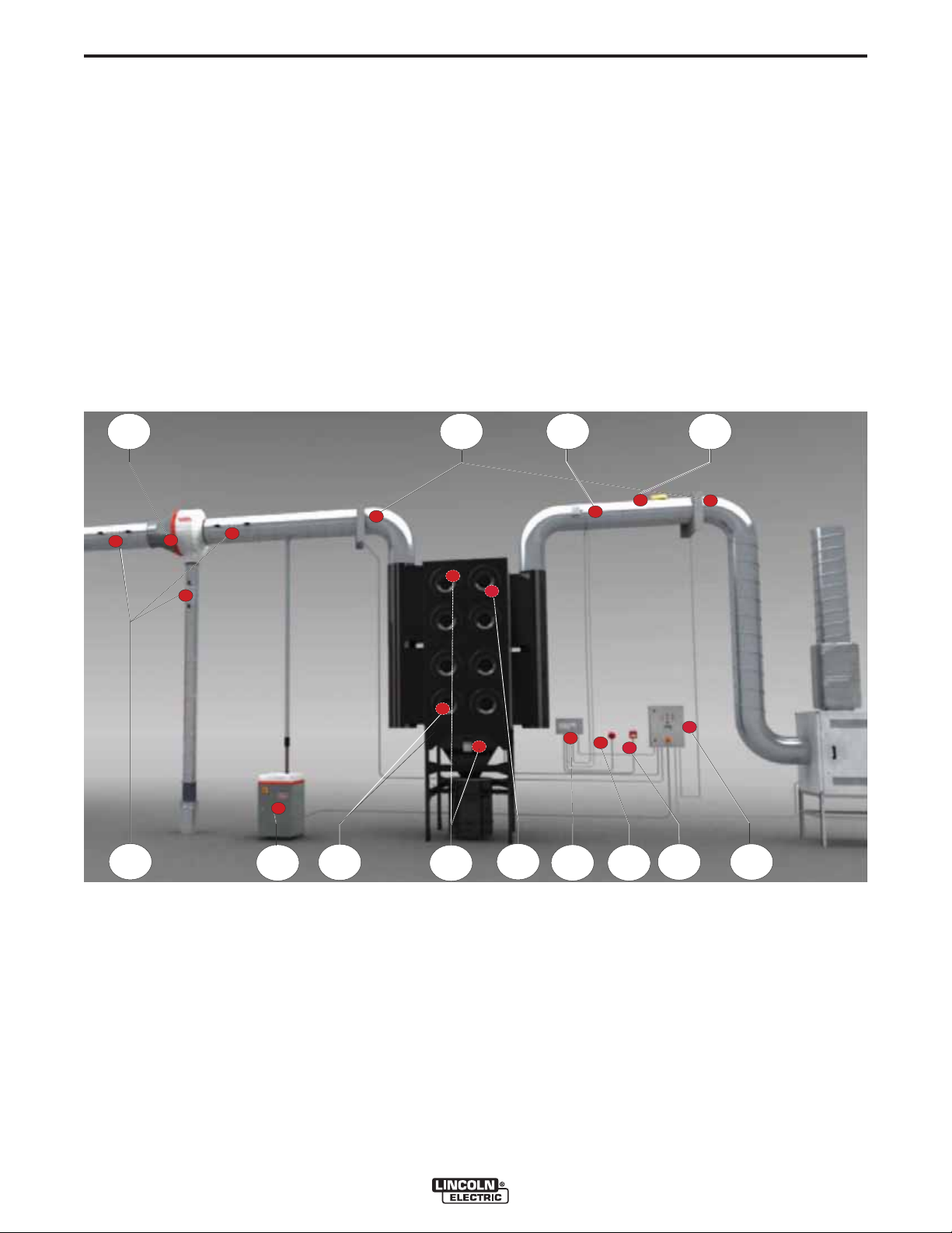
GUARDIAN™ CONTROL™ SOLUTIONS SYSTEM
COMPONENTS
A. Spark Guardian™
B. Sliding Valves
C. Spark Detectors
D. Smoke Detector
E. Inspection Hatches
F. Oil Guardian™
G. Solenoid Valve
FIGURE A.3 – GUARDIAN™ CONTROL™ SOLUTIONS SYSTEM COMPONENTS
INSTALLATION
A-13
H. Heat Detectors (located inside filter bank)
I. Flame Guardian™ (located inside filter bank)
J. Guardian™ Panel
K. Fire Alarm Sounder
L. Manual Call Point
M. System Control Panel (SCP)
A
E
F
G
B
H
I
C
J
K
L
D
M
GUARDIAN CONTROL™ SOLUTIONS
Page 21

A-14
INSTALLATION
SAFETY PRECAUTIONS
• Service and Repair should only be performed by
Lincoln Electric Factory Trained Personnel.
• Electric connections should be executed in accordance with local requirements. Ensure compliance
with the EMC regulatory arrangements.
• During installation, always use Personal Protective
Equipment (PPE) to avoid injury. This also applies to
persons who enter the work area during installation.
• Use sufficient climbing gear and safety guards when
working higher than 6 feet (local restrictions may
apply).
• Never install any product in front of entrances and
exits which must be used for emergency services.
• Do not move, puncture, cut or otherwise disturb any
gas, water pipes and/or electric cables.
• Make sure the wall, ceiling or support system is
strong enough to support the weight of the products
being mounted.
• Ensure the workspace is well illuminated.
• Use common sense. Stay alert and keep your attention to your work. Do not install the product when you
are under the influence of drugs, alcohol or medicine.
A-14
2. Electrical installer shall install System Control
Panel and wire between System Control Panel, fan
and filter. Also, Electrical installer shall install
Guardian™ Panel.
3. Controls installer shall install all detectors and
shall wire all low voltage devices including: heat,
smoke and spark detectors, solenoid valve, sliding
valves, Flame Guardian™, fire alarm sounder and
manual call point and interconnect to System
Control Panel from Guardian™ Panel.
NOTE: DO NOT wire in Flame Guardian™ aerosol
until after system is fully tested.
TOOLS AND REQUIREMENTS
• Connection Wire: 5 x 20 AWG
• Connection Wire: 5 x 20 AWG Shielded Cable
• Electric Drill
• Self-tapping Screws (various sizes)
• Mounting Material Guardian™ Panel
• Metal Cable Glands/Clamps
• Duct Support Material (depending on weight of sliding valves)
• Lifting And Climbing Gear
• Existing Duct: Angle Grinder Or Jigsaw
INSTALLATION AND COMMISSIONING
• Make sure that the installation location, contains sufficient approved fire extinguishers.
• Install according to the National Fire Protection
Association (NFPA) requirements and the state
and local authorities having jurisdiction.
WARNING
ELECTRIC SHOCK can kill.
• Do not touch electrically live parts or
electrode with skin or wet clothing.
• Insulate yourself from work and
ground
• Always wear dry insulating gloves.
------------------------------------------------------------------------
MOVING PARTS can injure.
•
Do not operate with doors open or
guards off.
• Stop engine before servicing.
• Keep away from moving parts.
------------------------------------------------------------------------
TYPICAL INSTALLATION SEQUENCE
1. Mechanical installer shall install fan, filter, Spark
Guardian™, sliding valves and related interconnecting ductwork. Also, mechanical installer shall set Oil
Guardian™ in place and route ductwork between Oil
Guardian™ and main duct.
To avoid accidental fire alarms and the activation of
Flame Guardian™ fire extinguishing generator(s), the
following installation and commissioning sequence
shall be followed. Deviation from this sequence is
allowed, as long as the fire extinguishing generator
is/are the last item(s) to be connected; even after having performed the functional tests.
1. Filter/fan installation
2. Spark Guardian™
3. Valves (sliding valves + solenoid valve)
4. Oil Guardian™
5. Flame Guardian™ fire extinguishing generators
(isolated)
6. System control panel
7. Guardian™ Panel (without power)
8. Detectors (heat, sparks, smoke)
See the full Commissioning Checklist for more information.
FILTER/FAN
See Filter / Fan Instruction Manual for detailed
installation instructions.
GUARDIAN CONTROL™ SOLUTIONS
Page 22
A-15
INSTALLATION
A-15
SPARK GUARDIAN™
GENERAL DESCRIPTION
The Spark Guardian™ is a cyclonic Spark arrester that
provides excellent protection against sparks and cigarette butts. Also it is an in-line pre-separator reducing
the dust load in the connected filtration system.
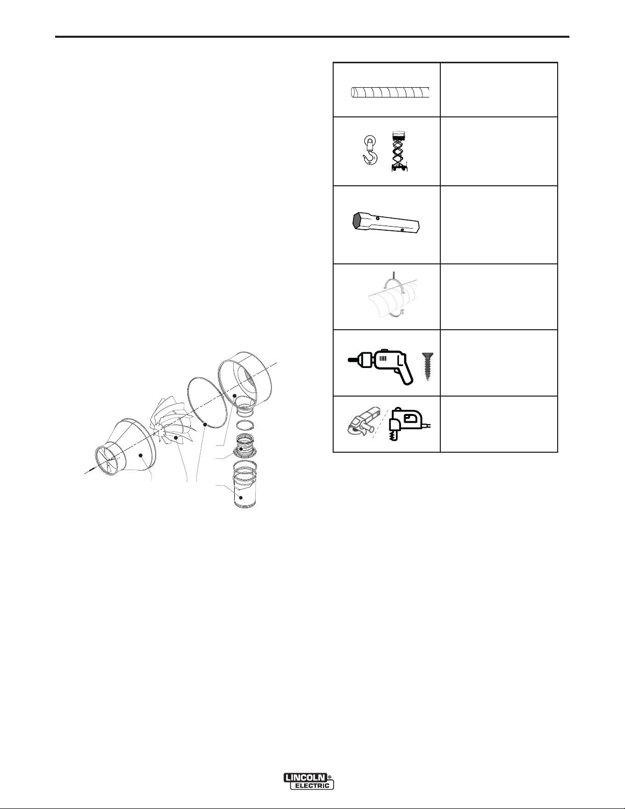
COMPONENTS
The product consists of the following main components
and elements:
See Figure A.4.
A. Inlet
B. Cyclone
C. Duct clamp
D. Outlet
E. Dustbin cover including connection flange and
hose
F. Dustbin
FIGURE A.4 – SPARK GUARDIAN™ COMPO-
NENTS
TABLE A.2
Duct >1 m Ø 200 mm/
8 inch (recommended)
Lifting and climbing
gear; e.g.
• Sling
• Fork-lift truck and pallet
• Scissor lift
Box spanner (or wrench):
• SparkShield-250/10:
M10 + M13
• SparkShield-400/16:
M10 + M13
• SparkShield-500/20:
M10 + M13 + M16
Duct support material
D
E
A B C
F
SAFETY
• Service and Repair should only be performed by
Lincoln Electric Factory Trained Personnel.
• Use sufficient climbing gear and safety guards when
working on a higher level than 6 feet (local restrictions may apply).
• Never install the product in front of entrances and
exits which must be used for emergency services.
• Make sure the wall, ceiling or support systems are
strong enough to support the weight of the product
being mounted.
Electric drill + selftapping screws
Existing duct:
• Angle grinder; or
• Jigsaw + electric drill
UNPACKING
Check that the product is complete. The package
should contain:
Spark Guardian™ 250/400/500 Components (See
Figure A.4)
• Spark Guardian™, consisting of inlet(A), Cyclone(B),
and outlet(D), connected by duct clamp(C)
• Dustbin 13 liters(F)
• Dustbin 27 liters(F)
• Dustbin cover incl. connection flange and hose(E)
For duct connection of Spark Guardian™: (See
Figure A.8)
• Connection ring (2) Ø 250/400/500 mm(A)
• Duct clamp (2) Ø 250/400/500 mm(B)
INSTALLATION
Tools and requirements
See Table A.2 for necessary tools to mount the product.
GUARDIAN CONTROL™ SOLUTIONS
For connection of vertical duct Ø 200 mm between
Spark Guardian™ and dustbin: (See Figure A.10)
• Connection ring (2) Ø 200 mm(A)
• Duct clamp Ø 200 mm(B)
Page 23
A-16
Spark Guardian™ 10/16/20 Components (See
Figure A.4)
• Spark Guardian™, consisting of inlet(A), Cyclone(B)
and outlet(D), connected by duct clamp(C)
• Dustbin 13 liters(F)
• Dustbin 27 liters(F)
INSTALLATION
A-16
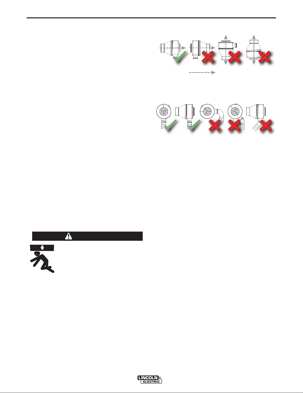
FIGURE A.5 – AIRFLOW DIRECTION
• Dustbin cover incl. connection flange and hose(E)
For duct connection of Spark Guardian™: (See
Figure A.8)
• Reducer (2) from metric Ø 250/400/500 mm. to imperial Ø 10/16/20 in.(A)
• Duct clamp (2) Ø 200/400/500 mm(B)
For connection of vertical duct Ø 8 in. between
Spark Guardian™ and dustbin: (See Figure A.10)
• Reducer (2) from metric Ø 200 in. to imperial Ø 8
in.(A)
• Duct clamp Ø 200 mm(B)
If parts are missing or damaged, contact your supplier.
MOUNTING
Spark Guardian™
The Spark Guardian™ can be mounted:
• During installation of new ductwork.
• Afterwards in an existing duct.
Airflow direction
FIGURE A.6 – PERPENDICULAR WITHOUT
BENDS
Perpendicular without bend(s)
2. In case of installation in an existing duct: cut away a
piece of the existing duct. See Figure A.7 on (D) for
duct length to be removed.
• Allow sufficient space between the duct and the wall
to install the Spark Guardian™.
WARNING
Lifting the Spark Guardian™ in an
incorrect manner can cause injury of
death.
The Spark Guardian™ can be mounted as a whole. Lift it using (e.g.):
• Sling
• Forklift-truck with pallet
When no lifting gear is available, it is recommended to mount the inlet and outlet separately and to
reconnect them afterwards.
-----------------------------------------------------------------------
To mount the Spark Guardian™, proceed as follows.
1. Observe the mounting instructions as indicated in
Figure A.5 and Figure A.6.
GUARDIAN CONTROL™ SOLUTIONS
Page 24
A-17
INSTALLATION
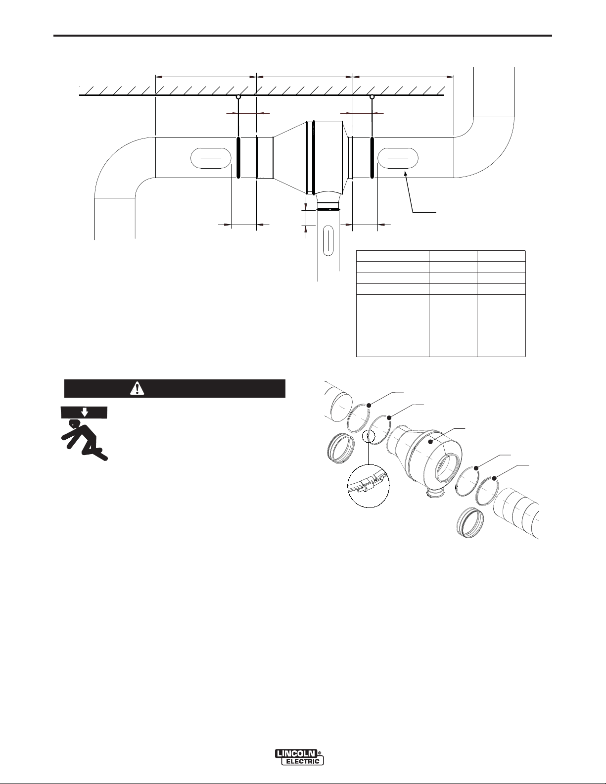
FIGURE A.7
A-17
3. Support the loose ends of the duct.
DA
BB
A
INSPECTION
E
CC
A
B
C
D
SparkShield-250
SparkShield-400
SparkShield-500
SparkShield-10
SparkShield-16
SparkShield-20
E
HATCH (TYP.-3)
mm inch
min. 1000 min. 40
± 175 ± 7
± 250 ± 10
-800
-970
- 1180
-915
- 1085
- 1295
± 150 ± 6
-31.5
-38.2
-46.5
-36.0
-42.7
-51.0
FIGURE A.8 – SPARK GUARDIAN™ MOUNTING
WARNING
Duct supports shall be designed to
support the weight of the Spark
Guardian™. See Technical
Specifications for weight of Spark
Guardian™ in question.
-----------------------------------------------------------------------
See Figure A.8.
4. Loosen all duct clamps(B).
5. Slide a duct clamp(B) Ø 250/400/500 mm over both
of the Spark Guardian(s)™(C).
• Duct metric size (mm):
Place a connection ring Ø 250/400/500 mm (A) in
both duct ends and fasten them using self-tapping
screws (min. 6).
• Duct imperial size (inch):
Place a reducer metric-imperial Ø 10/16/20 (A) in
both duct ends and fasten them using self-tapping
screws (min. 6).
6. Lift the Spark Guardian™ (C) in line with the duct
and mount it to the connection rings using the duct
clamps (B). Tighten the clamps using a box wrench.
A
B
mm
inch
C
B
A
mm
inch
DUSTBIN
The Spark Guardian™ comes with two different dustbins, which can be optionally mounted.
Recommended use:
• Spark Guardian™-250/400/10/16: dustbin 13 liters
• Spark Guardian™-400/500/16/20: dustbin 27 liters
The dustbin can be placed on the floor or on a frame
or small platform.
GUARDIAN CONTROL™ SOLUTIONS
Page 25

A-18
INSTALLATION
NOTE: Although it is possible to mount the dustbin
directly to the Spark Guardian™, the installation of a vertical duct of at least 3 feet between
Spark Guardian™ and dustbin enhances fire
safety. The larger the distance to the dustbin,
the safer. Do not mount the dustbin in a “hanging” position. A structure that is capable of
supporting a full dustbin (100 lbs.) is necessary
and shall be in place at all times under the
dustbin.
NOTE: For weight reasons it is recommended to place
the dustbin on a small pallet to facilitate
removal.
To mount the dustbin, proceed as follows.
A-18
Place a reducer metric-imperial Ø 8 in. (B) at either
side of the duct and fasten them using self-tapping
screws (min. 4).
1. Connect the duct to the Spark Guardian™ using a
duct clamp (A). Tighten the clamp using a box
wrench.
2. Place the dustbin underneath the duct.
3. Connect it to the duct using the duct clamp (C).
Tighten the clamp using a box wrench.
FIGURE A.10 – DUSTBIN MOUNTING
VIA VERTICAL DUCT
1. Observe the mounting orientations indicated in
Figure A.6.
See Figure A.9.
2. Place the dustbin cover (B) on the dustbin of your
choice and connect it using the quick connect coupling (C).
FIGURE A.9 – DUSTBIN MOUNTING
A
B
C
Direct mounting to Spark Guardian™:
1. Place the dustbin underneath the Spark Guardian™.
2. Connect it to the Spark Guardian™ using the duct
clamp (A).
3. Tighten the clamp using a wrench.
B
inch
A
B
inch mm
mm
C
INSPECTION HATCHES (RECOMMENDED
OPTION)
See Figure A.7 for recommended position of the
inspection hatches.
1. Make cut outs in the horizontal and/or vertical duct
using the template supplied with the inspection
hatches.
2. Insert the hatches in the cut outs.
3. Turn the handles 90° to fasten them and make the
ducts airtight.
NOTE: Refer to the mounting instruction supplied with
the inspection hatches.
In this case the following parts become unnecessary:
• Connection ring (2) Ø 8 in. (200 mm)
• Duct clamp Ø 7.87 in. (200 mm)
Mounting via vertical duct Ø 200 mm/8 inch: (See
Figure A.10.)
• Duct metric size (mm):
Place a connection ring Ø 200 mm (B) at either side
of the duct and fasten them using self-tapping screws
(min. 4).
• Duct imperial size (inch):
GUARDIAN CONTROL™ SOLUTIONS
MANUAL DAMPER (OPTION)
The manual damper can be installed in any appropriate position in the vertical duct.
The function of the manual damper is to allow for the
dumping of the dustbin without shutting off the system.
1. Install the manual damper in accordance with the
instruction sheet supplied with the damper.
2. Open the damper by turning the handle in vertical
position.
Page 26

A-19
SLIDING VALVES
FIGURE A.11
INSTALLATION
The sliding valves can be mounted:
• During installation of a new ductwork
A-19
C
B
A
F
E
D
DESCRIPTION
When the filter system is in operation, the sliding
valves are open. In the event of an alarm signal, power
failure or when the fan is switched off, the valves are
closed. Correct closing of the valves is monitored by a
reed switch contact.
In case of fire, the sliding valves close automatically.
This cuts off oxygen to the fire. This will also minimize
risk of escalation and spreading of smoke.
• In an existing duct
WARNING
Not installing the proper supports for
the Sliding Valves can cause severe
injury.
Ensure that the ductwork can support the weight of the sliding valves.
It is recommended to use duct supports.
-----------------------------------------------------------------------
To mount the sliding valves, proceed as follows.
Sliding valve type SV-10:
See Figure A.12.
1. Place the bracket (B) over the cylinder.
2. Place the reed contact (A) in the slit of the bracket.
FIGURE A.12
A
COMPONENTS: (See Figure A.11)
A. Sliding valves incl. 5/2 solenoid valve
B. Connection flange (2)
C. Quick connect coupling (2)
D. Junction box
E. Cable gland/clamp (3)
F. Reed contact (See Figure A.12 for more details)
LOCATION
• 1st sliding valve: in filter inlet duct as close to the filter bank as possible.
• 2nd sliding valve: in filter outlet duct as close to the
filter bank as possible.
• Mounted in vertical position.
It is strongly recommended that the sliding valves be
installed indoors. If they are installed outside, however,
ensure that they are protected from rain and snow.
Avoid installation where compressed air can cool down
below its dew point to prevent damage to the pneumatics.
NOTE: Allow sufficient space above the duct for the
sliding valves to fully open;
• SV-10: + 14 in.
• SV-12: + 16 in.
• SV-16: + 20 in.
• SV-20: + 26 in.
• SV-24: + 32 in.
B
All other sliding valves:
See Figure A.13.
1. Place the reed contact (A) in the slit of the cylinder.
2. Attach it by fastening the screw.
FIGURE A.13
A
See Figure A.14, for steps 3-6.
3. In case of installation in an existing duct: cut away a
piece of the existing duct as shown in the table
below.
GUARDIAN CONTROL™ SOLUTIONS
Page 27

A-20
INSTALLATION
A-20
Type of sliding valve Duct length to be removed
.ni 4.0 -/+ .ni 6.1101-VS
.ni 4.0 -/+ .ni 6.1121-VS
.ni 4.0 -/+ .ni 6.1161-VS
.ni 4.0 -/+ .ni 0.5102-VS
.ni 4.0 -/+ .ni 0.5142-VS
4. Slide a connection flange (B) into both duct ends
(A).
5. Place the sliding valve (D in between and fasten it
using the quick connect couplings (C).
6. Fasten the connection flanges using self-tapping
screws.
NOTE: The valves must be mounted straight and
without tension on the shell/housing to guarantee airtightness and to avoid noise from airflow.
FIGURE A.14
A
B
C
D
C
B
A
COMPRESSED AIR CONNECTION
FIGURE A.15
Compressed air specifications
Compressed air connection
Recommended operational pressure 4-5 bar (max. 9 bar)
1. Connect the sliding valves to compressed air source
per the Pneumatic Diagram.
Setting closing speed of the sliding valves
The closing speed of the valves is set by the air pressure.
1. Set the closing speed of the valves to 4-5 seconds
by adjusting the air pressure to 5 BAR.
Do not set the valves to faster than 4 seconds. If there
is a fire alarm, the fan is switched off and the sliding
valves are closed. The 4 seconds gives the fan enough
time to reduce speed and prevents damage to the duct
by negative pressure. Do not select speeds slower
than 5 seconds, since the Flame Guardian™ modules
are activated 5 seconds after the fire alarm.
Post installation checks
• Check electrical connections.
• Check pneumatic connections.
• Check that nuts and bolts are secure.
6 mm
ISO 8573-3 class 6
ot gnidrocca eerf-lio dna yrdytilauQ
WARNING
Moving parts can cause injury.
If valve is mounted in an accessible
area, provide shroud and warning
label to prevent access.
-----------------------------------------------------------------------
ELECTRICAL CONNECTION
To be sourced locally:
• Connection wire: 5 x 20 AWG cable
Wiring
1. Connect the sliding valves to the system control
panel in accordance with the Electrical Wiring
Diagram.
2. Connect the reed contacts to the system control
panel in accordance with the Electrical Wiring
Diagram.
GUARDIAN CONTROL™ SOLUTIONS
Page 28

A-21
INSTALLATION
FUNCTIONAL TESTING (GENERAL)
NOTE: Before performing any functional testing make
sure the Flame Guardian™ is disconnected to
prevent unwanted discharge. See Wiring
Diagram.
To perform any functional test, the following instructions should be followed.
1. Ensure that the Flame Guardian™ module(s) is/are
not connected to a power source.
2. Perform the desired Functional Test. Sound alarm
will go off.
3. Check fire zone.
4. Press the SIGNAL SILENCE button on the
Guardian™ Panel to suppress alarm.
5. Press the SYSTEM RESET button.
To proceed with testing:
• Restart procedure.
If testing has been completed:
A-21
• Reconnect the Flame Guardian™ module(s).
• Make sure the panel is in RUN mode.
FUNCTIONAL TEST (SLIDING VALVES)
The sliding valves can be tested manually by pushing
the test button (A) on the 5/2 solenoid valve.
FIGURE A.16
A
• Functionally test both sliding valves.
• Refer to the Pneumatic Diagram for more details
GUARDIAN CONTROL™ SOLUTIONS
Page 29

A-22
INSTALLATION
A-22
SOLENOID VALVE
FIGURE A.17
SOLENOID
VALVE
DESCRIPTION
See Figure A.18.
Normally closed 3-way 2-position solenoid valve.
When the connected filter system is in operation, the
solenoid is activated and compressed air is supplied to
the cleaning system of the filter (port P and A are
open). If there is a fire alarm or power failure, the solenoid will return to its normally closed (NC) position,
closing port P and opening port R. In this position the
compressed air escapes from the pressure tanks. It
also prevents fresh oxygen from reaching the filter.
FIGURE A.18 – SOLENOID VALVE
LOCATION
The solenoid valve is placed in the main compressed
air line between pressure reducer and filter unit. It is
recommended to mount the valve on the filter housing.
• Mount the solenoid valve at an accessible location.
• Refer to the Pneumatic Diagram for more details
ELECTRICAL CONNECTION
To be sourced locally:
• Connection wire: 5 x 20 AWG
Wiring
1. Connect the solenoid valve to the system control
panel in accordance with the Electrical Wiring
Diagram.
Compressed air connection
The solenoid valve is fitted with a 12 mm compressed
air tube connection.
1. Connect the solenoid valve to compressed air.
2. Check compressed air connections of filter system.
A
P
R
A
PR
COMPONENTS
• 3/2 solenoid valve, including electrical entry terminal
and 2 swivel elbow adapters
• Screw M4x35 (2)
• Washer M4 (2)
• Locknut M4 (2)
GUARDIAN CONTROL™ SOLUTIONS
Page 30

A-23
INSTALLATION
A-23
FUNCTIONAL TESTING (GENERAL)
NOTE: Before performing any functional testing make
sure the Flame Guardian™ is disconnected to
prevent unwanted discharge. See Wiring
Diagram.
To perform any functional test, the following instructions should be followed.
1. Ensure that the Flame Guardian™ module(s) is/are
not connected to power source.
2. Perform the desired Functional Test. Sound alarm
will go off.
3. Check fire zone.
4. Press the SIGNAL SILENCE button on the
Guardian™ Panel to suppress alarm.
5. Press the SYSTEM RESET button.
To proceed with testing:
• Restart procedure.
If testing has been completed:
• Reconnect the Flame Guardian™ module(s).
OIL GUARDIAN™ INSTALLATION
See Oil Guardian™ Instruction Manual for detailed
instalation instructions.
• Make sure the panel is in RUN mode.
FUNCTIONAL TEST (SOLENOID VALVE)
The solenoid valve is provided with a button for testing
purposes.
1. Press button (A) and check that the compressed air
escapes from outlet R (B). See Figure A.19.
FIGURE A.19
A
A
P
R
B
GUARDIAN CONTROL™ SOLUTIONS
Page 31

A-24
FLAME GUARDIAN™
FIGURE A.20
5.
3.
6.
DESCRIPTION
INSTALLATION
A-24
If Flame Guardian™ is stored in accordance with the
above mentioned conditions, shelf life of the aerosol
generator is 10 years.
2.
INSTALLATION
• See Figure A.22 for the required number, type and
1.
4.
position of Flame Guardian™ generator in Statiflex
filter bank filter system.
NOTE: Failure to use the correct number, type and
position of the Flame Guardian™ generators
could compromise the effective fire response.
See Figure A.22 for number, type and position
of Flame Guardian™ generators.
The Flame Guardian™ is a fire suppression generator
designed to be installed directly into the filter system.
The Flame Guardian™ is activated by the Guardian™
Panel fire detection panel 5 seconds after a fire alarm
is activated.
The Flame Guardian™ is designed to suppress or
extinguish filter fires of EN 2 Class A and NFPA 10
Class A (normal or solid combustible material in the filters).
In 5 to 10 seconds, after a fire is detected, the filter is
filled with a potassium aerosol. This material reacts
with the free radicals in the flame. The free radicals
react with the aerosol instead of the fuel and the chain
reaction of fire is suppressed. The residue is a negligible amount of harmless and stable potassium hydroxide salt (KOH).
After release of the aerosol, it remains active for at
least 30 minutes, this prevents the fire from reigniting.
COMPONENTS:
1. Flame Guardian™ (200 or 500 g)
2. Mounting bracket (two piece)
COMPONENT LOCATIONS
See Figure A.21 and Figure A.22.
A. Filter cartridge
B. Junction box
C. Framework Statiflex filter bank (SFB)
D. Flame Guardian™ Frame
E. Flame Guardian™ (200 or 500)
F. Drilling Template (Not shown)
FIGURE A.21
MDB
A
HIGH
TEMPERATURE
LEAD
B
C
3. Junction box
4. Metal cable gland/clamp
5. Plastic cable gland/clamp (2)
6. Mounting material
TRANSPORT AND STORAGE
To avoid damage, the following conditions for transport
and storage should be adhered to.
- Do not drop.
- Store between -58 and +212°F (-50 and +100°C).
- Relative humidity during transport and storage: max.
98%.
GUARDIAN CONTROL™ SOLUTIONS
E
D
A
To install Flame Guardian™, proceed as follows.
See Figure A.23.
1. Connect one end of the High Temperature Lead to
the Flame Guardian™ Container. Leads are not
polarity sensitive.
2. Place the Connection Terminal inside the end of the
Flame Guardian™ Container and route the High
Temperature lead through the metal Strain Relief
Assembly, tighten. See Figure A.23. See Wiring
Diagram.
Page 32

A-25
INSTALLATION
FIGURE A.22 – NUMBER, TYPE AND LOCATION OF FLAME GUARDIAN™
GENERATORS PER STATIFLEX FILTER BANK
MDB-4 MDB-6 MDB-8/V MDB-8/H MDB-10
1x FS-200 1x FS-200 1x FS-500 1x FS-500 1x FS-500
A-25
MDB-12 MDB-12/V MDB-12/H MDB-16 MDB-16/H
1x FS-500 1x FS-500 1x FS-500 1x FS-500 1x FS-500 1x FS-500
MDB-20 MDB-24/H MDB-24/V MDB-32/H
1x FS-500 1x FS-500 1x FS-500 2x FS-500
1x FS-200 1x FS-200
1x FS-200
MDB-16/V
MDB-36 MDB-48/H MDB-48/V
2x FS-500 2x FS-500 2x FS-500
GUARDIAN CONTROL™ SOLUTIONS
Page 33

A-26
INSTALLATION
A-26
FIGURE A.23
MDB
HIGH
TEMPERATURE
LEAD
3. Loosely assemble mounting brackets. Hand tighten bolts, washers and locknuts. See Figure A.24.
4. Pre-drill two 5/16” holes exactly 3 3/16” apart on
front of filter housing. Use provided drilling template.
5. Using #13 bolts, washers and locknuts, secure
mounting brackets to filter housing. See Figure
A.21.
FIGURE A.24
F
C
A
B
D
E
SFB
6. Insert Flame Guardian™ Container into mounting
brackets previously installed. See Figure A.24.
7. Mount junction box to front of filter housing. Using
self tapping #10 x 3/4” screws. (not supplied).
NOTE: Mount with holes vertical. Pay attention
to components located behind mounting holes.
8. Install plastic cable gland and high temperature
lead into workbox. See Figure A.24.
9. Connect low voltage shielded signal wire to the
leads from the flame guardian™ assembly.
10. Connect the low voltage shielded signal wire to
output #2 connection on the control unit. See
Wiring Diagram.
ELECTRICAL CONNECTION
To be sourced locally:
• Connection Wire: 5 x 20 AWG
Connection to Guardian™ Panel
• Place an End Of Line diode supplied with the
Guardian™ Panel in the junction box in series with
each Flame Guardian™, in accordance with the
Electrical Wiring Diagram.
POST INSTALLATION CHECKS
Before performing the functional test, check the following mounting instructions.
• Wiring from and to the Guardian™ Panel.
• End Of Line resistor-diode in junction box.
• Correct position and flow angle (10°) of Flame
Guardian™.
• Secure all nuts and bolts.
GUARDIAN CONTROL™ SOLUTIONS
Page 34

A-27
INSTALLATION
FUNCTIONAL TESTING (GENERAL)
A-27
True Functional test
NOTE: Before performing any functional testing make
sure the Flame Guardian™ is disconnected to
prevent unwanted discharge. See Wiring
Diagram.
To perform any functional test, the following instructions should be followed.
1. Ensure that the Flame Guardian™ module(s) is/are
not connected to a power source.
2. Perform the desired Functional Test. Sound alarm
will go off.
3. Check fire zone.
4. Press the SIGNAL SILENCE button on the
Guardian™ Panel to suppress alarm.
5. Press the SYSTEM RESET button.
To proceed with testing:
• Restart procedure.
If testing has been completed:
• Reconnect the Flame Guardian™ module(s).
• Make sure the panel is in RUN mode.
WARNING
Use Personal Protective Equipment
(PPE) to protect from exposure to
sparks.
-----------------------------------------------------------------------
A true functional check can be done by replacing the
Flame Guardian™ module with a detonation simulator.
A “Fire Like” condition can be simulated by removing
one of the spark detectors. After the fire alarm the detonation simulator will be activated showing a small
flash
1. Perform a Functional Test as described above.
2. Reset activated detector.
3. Press the SYSTEM RESET button on the
Guardian™ Panel.
4. Turn the control panel OFF for 20 seconds and then
back ON.
5. Reconnect the Flame Guardian™ module(s).
FUNCTIONAL TEST (FLAME
GUARDIAN™)
A functional test can be done in two ways:
• By simulation
• True functional test
Simulation
1. Two heat resistant wires are connected to an internal metal spiral activator in the Flame Guardian™.
The spiral is heated by the current and starts an
exothermic chemical reaction that releases the
aerosol. The minimum amount of energy needed to
start the reaction is created by applying 12V/0.8
Amps for 3-4 seconds.
2. The internal wiring of the activator can be inspected
by measuring the internal ohm resistance of 2 ohm
+/- 0.2 ohm using an ohm meter with a current less
than 5 milliamps. This inspection can be done in the
junction box mounted on the outside of the filter by
measuring the ohm resistance over the heat resistant wires.
3. Check electrical activation of the Flame Guardian™
modules according to the above instructions.
WARNING
Keep away from flammable material
and do not hold in the hand.
-----------------------------------------------------------------------
SYSTEM CONTROL PANEL
See System Control Panel Manual for detailed
Installation instructions.
GUARDIAN CONTROL™ SOLUTIONS
Page 35

A-28
INSTALLATION
A-28
GUARDIAN™ PANEL
FIGURE A.25 – GUARDIAN™ PANEL
DESCRIPTION
Guardian™ Panel is a fire detection panel (UL
Standard 862) with a separate manual call point. It has
three detection zones all of which are capable of activating the Flame Guardian™ fire extinguishing
aerosols.
The panel makes it possible to connect additional manual call points.
The Guardian™ Panel has two back-up batteries to
allow for continuous operation in the event of a power
failure.
COMPONENTS:
• Fire Detection Panel
• Battery Pack (2)
• Fire Alarm Sounder
• Manual Call Point
• End Of Line Resistor-diode
• Detonation Simulator
• Key (2 Sets)
AMBIENT CONDITIONS
- Min. temperature: 23°F (-5°C)
- Max. temperature: 104°F (+40°C)
- Relative humidity: max. 95%
The Guardian™ Panel housing is NEMA 1 rated. It
must be shielded from excessive dust, welding sparks
and grinding sparks, if any, by an enclosure.
To install the Guardian™ Panel, proceed as follows.
1. Mount the Guardian™ Panel at all four mounting
points. Use suitable fixtures so that the panel cannot move after it has been installed.
FIRE ALARM SOUNDER
Installation, tone selection and volume control of the fire alarm
sounder are described in the installation manual supplied with the
product.
1. Mount the fire alarm sounder at an appropriate location so the operator can hear it while working.
2. Select the desired tone.
3. Adjust the volume to the desired level.
ELECTRICAL CONNECTION
See Figure A.26. Also See Wiring Diagram.
Guardian™ Panel (D) must be wired to:
• 2 Heat Detectors (J)
INSTALLATION
To be sourced locally:
• Connection Wire: 5 x 20 AWG Shielded Cable
• Mounting Material
• Metal Cable Clamp/Glands
LOCATION
• On the wall or at a convenient location close to the
filter installation
• At eye level
• Indoors
NOTE: Do not mount the Guardian™ Panel close to
sources of excessive heat.
GUARDIAN CONTROL™ SOLUTIONS
• 1 Spark Detector Set (Set of 2) (H)
• 1 Smoke Detector (I)
• Fire Alarm Sounder (included in Guardian™
Panel package) (C)
• Manual Call Point (included in Guardian™ Panel
package) (B)
• System Control Panel SCP (E)
• Flame Guardian™ Fire Extinguishing Generators
Guardian Panel (D) activates:
• Flame Guardian™ Fire Extinguishing
Generator(s) (A)
• Fire Alarm Sounder (C)
• System Control Panel SCP (E)
System control panel SCP (E) activates:
• Sliding Valves (G)
• Solenoid Valve (F)
Page 36

A-29
INSTALLATION
FIGURE A.26 – ELECTRICAL CONNECTIONS
EF
A-29
A
BC
F
D
JIH
FIGURE A.27 – GUARDIAN CONTROL™ PANEL
GUARDIAN CONTROL™ SOLUTIONS
Page 37

A-30
All connections for field wiring are to the terminal strips
along the top and bottom of the circuit board. See
Figure A.27. Also See Wiring Diagram.
Cables to be used:
• 5 x 20 AWG shielded cable for detectors and
manual call point
• 5 x 20 AWG normal cable for other wiring
The resistance of any core of any cable should not
exceed 25 ohm(>1640 ft for 20 AWG).
To connect the cables to the Guardian™ Panel, use
suitable metal cable glands fitted to the knock-outs
provided.
1. Connect all cables to the Guardian™ Panel in accordance with the Electrical Wiring Diagram.
The wiring of the detectors, manual call point, Flame
Guardian™ and fire alarm sounder is monitored for
open circuit fault conditions. See Wiring Diagram.
INSTALLATION
BATTERY PACKS
A-30
The Guardian™ Panel is fitted with
battery leads wired to the circuit board
to connect the two battery packs.
1. Place both battery packs inside the Guardian™
Panel.
2. Connect them to the battery leads.
NOTE: It is extremely important for the polarity of the
batteries to be connected correctly. Incorrect
connections could damage the control panel.
MAIN SUPPLY
The main supply of 115V/230V AC must be connected
to a dedicated circuit. See Wiring Diagram.
1. Connect the Guardian™ Panel to the main in accordance with the Electrical Wiring Diagram.
GUARDIAN CONTROL™ SOLUTIONS
Page 38

A-31
INSTALLATION
A-31
MANUAL CALL POINT
FIGURE A.28 – MANUAL CALL POINT
DESCRIPTION
Manual pull station is a switch used to activate the fire
alarm and fire suppression system.
To operate push in the bar marked “PUSH” and pull the
handle marked “PULL” on the front of the unit as far
down as it will go. At that point, the handle will lock in
place and will be easily visible up to 50 feet away.
COMPONENTS:
ELECTRICAL CONNECTION
To be sourced locally:
• Connection Wire: 5 x 20 AWG Shielded Cable
See Figure A.29.
1. Connect the manual call point to Zone 4 of the
Guardian™ Panel in accordance with the Electrical
Wiring Diagram.
2. Take the End Of Line resistor 5k ohm mounted in
the terminal strip of Zone 4 and place it in the terminal strip of the manual call point (A).
FIGURE A.29 – ELECTRICAL CONNECTION
field wiring
A
REOL
terminal strip
NO
red
white
NC
toggle
switch
• Manual Call Point
• Key
LOCATION
• Where it will be easy for the operator to reach it
• Indoors
NOTE: Do not mount the manual call point to the filter
system. It may not be accessible if there is a
fire.
RESET
1. Using the proper key, open the cover.
2. Move the toggle switch into the “on” or “run” position.
3. Place the “push” and “pull” handles back into thier
ready positions. See Figure A.29.
4. Close and lock cover.
GUARDIAN CONTROL™ SOLUTIONS
Page 39

A-32
INSTALLATION
HEAT DETECTOR SET
FIGURE A.30 – HEAT DETECTOR SET (2)
GLANDS
HEAT
DETECTORS
NUTS
DESCRIPTION
The Heat Detector Set consists of two temperature
detectors that are installed in the filter housing. When
they detect a temperature of 190°F (88°C) or more,
they send a signal to the Guardian™ Panel to activate
the fire suppression system.
A-32
See Figure A.32.
1. Drill the appropriate size hole in the sheet metal.
2. Mount the heat sensors in the filter housing(s) and
hopper(s); A = housing/hopper.
FIGURE A.32 – HOUSING / HOPPER
SHEET
A
METAL
ELECTRICAL CONNECTION -ZONE 2-
To be sourced locally:
COMPONENTS:
• Heat Detector (2) With Junction Box (2)
• Cable Gland M25 (2)
• Nut Cable Gland M25 (2)
• Cable Gland M16 (4)
LOCATION
See Figure A.31.
• 1st heat sensor: on top of filter housing (A)
• 2nd heat sensor: in hopper just above dustbin (B)
• 1 heat detector set per filter module (number of hoppers = number of heat detector sets)
FIGURE A.31 – HEAT SENSOR LOCATIONS
A
C
A
B
B
• Connection Wire: 5 x 20 AWG Shielded Cable
Wiring
One or more sets of temperature detectors must be
wired in parallel. The detectors act as one sensor and
are connected to Zone 2 (See Electrical Wiring
Diagram).
1. Connect the heat sensors using shielded cables.
See Wiring Diagram.
End of line resistor
The last detector that is wired to the fire detection
panel Guardian™ Panel must be fitted with an End Of
Line resistor according to Figure A.33. The End Of Line
resistor of the heat detector is supplied with the fire
detection panel and can be found in Zone 2 of the relevant terminal.
1. Take the End Of Line resistor from Zone 2 of the
Guardian™ Panel and place it in the last heat detector. See Figure A.33.
The End Of Line resistor makes it possible for the fire
detection panel to monitor the system for an open circuit.
FIGURE A.33 – HEAT SENSOR WITH
END OF LINE RESISTOR
black
from other detector
RAL REOL
white
or panel
NOTE: It may be necessary to place sensors on the
front of filter housings when units are stacked.
GUARDIAN CONTROL™ SOLUTIONS
2x black 2x white
Page 40

A-33
INSTALLATION
Figure A.34 shows the first heat sensor without End Of
Line resistor.
FIGURE A.34 – HEAT SENSOR WITHOUT
END OF LINE RESISTOR
to next detector
black
from other detector
RAL
black
white
2x black 2x white
white
or panel
Alarm resistor
The heat detectors are fitted with a 470 ohm alarm
resistor (RAL) placed in series with a switching contact
circuit. The alarm resistors have no active function and
do not interfere with the functionality of the Guardian™
Panel fire detection panel.
NOTE: Shielded cables must be used. Not using
shielded cables can lead to a false alarm
induced by external high voltage sources.
FUNCTIONAL TESTING (GENERAL)
NOTE: Before performing any functional testing make
sure the Flame Guardian™ is disconnected to
prevent unwanted discharge. See Wiring
Diagram.
A-33
FUNCTIONAL TEST (HEAT DETECTORS)
ATTENTION
Notify all parties in the work area before testing the
fire safety system; See Maintenance Section.
------------------------------------------------------------------------
The operation of the heat detectors can be checked in
two ways;
1. By measuring the ohm resistance:
A. Gently heat the detectors using a heat gun or
heat lamp.
WARNING
Do not use open flames to test Heat
Detectors.
Keep heat source away from filters
and other flammable materials.
Using an open flame source may cause a fire and
result in injury or death.
------------------------------------------------------------------------
2. By connecting them to the fire detection panel:
A. Gently heat the detectors using a heat gun or
heat lamp.
B. Check the system status. Guardian™ Panel
should indicate a fire in Zone 2.
NOTE: Do not heat the detector to more than 131°F
(55°C) because this can change the default
temperature setting.
To perform any functional test, the following instructions should be followed.
1. Ensure that the Flame Guardian™ module(s) is/are
not connected to power source.
2. Perform the desired Functional Test. Sound alarm
will go off.
3. Check fire zone.
4. Press the SIGNAL SILENCE button on the
Guardian™ Panel to suppress alarm.
5. Press the SYSTEM RESET button.
To proceed with testing:
• Restart procedure.
If testing has been completed:
• Reconnect the Flame Guardian™ module(s).
• Make sure the panel is in RUN mode.
GUARDIAN CONTROL™ SOLUTIONS
Page 41

A-34
SPARK DETECTOR SET
FIGURE A.35 – SPARK DETECTOR SET (2)
INSTALLATION
The spark detectors can be mounted without having
access to the inside of the duct. In this case you will
need the supplied insertion tool.
A-34
SPARK
DETECTOR(S)
INSERTION
TOOL
JUNCTION
BOX
DESCRIPTION
There is a set of two infrared spark detectors. The
spark detectors are sensitive to the near IR light
between 0.4 to 1.1 microns wavelength.
When glowing particulate from the burning filter enters
the field of view on the detector, the detector responds
by sending a signal to the Guardian™ Panel fire detection panel. The Guardian™ Panel activates the fire
suppression system.
COMPONENTS:
• Spark detector with alarm resistor and mounting
screw
• Spark detector End Of Line Resistor with alarm resis-
tor and mounting screw
• Junction box
• Installation set (hole saw Ø 1.5 inches (38 mm) and
insertion tool)
LOCATION
• In filter outlet duct
• Face to face (180° apart from each other) in the same
horizontal plane (3 OʼClock - 9 OʼClock)
• Minimum 2.5 times duct diameter from bend or
branch Example: If duct is 12 inches in diameter the
spark detector placement must be at least 30” away
from a bend or branch.
NOTE: To avoid dirtying the lens, never mount the
spark detectors on the bottom of the duct.
Sensors shall be mounted @ 3 and 9 oʼclock.
NOTE: Installation is easier if the inside of the duct is
accessible.
In case of a new or disconnected duct allowing
access to the inside, proceed as follows.
See Figure A.36.
1. Make a hole Ø 1.5 in. (38 mm) in the duct using the
supplied hole saw.
2. Mount the flange (D) in the duct using the split washer (C), washer (B) and nut (A).
3. Tighten washer and nut on the flange.
FIGURE A.36
B
A
C
D
If there is no access to the inside of the duct, proceed
as follows.
See Figure A.37.
1. Make a hole Ø 1.5 in. (38 mm) in the duct using the
supplied hole saw.
2. Slip nut (B), washer (C) and split washer (D) on the
insertion tool (A) until the tool fits tightly on the
flange (E). The nut and washer should be loose on
the shaft of the tool.
3. Push the flange completely through the hole in the
duct and insert the split washer by rotating it into the
inside of the duct. Adding a gentle bend to the split
washer may be necessary.
4. Gently pull the flange back through the hole with the
insertion tool so it rests against the split washer
inside the duct.
5. Tighten washer and nut on the flange.
6. Remove the insertion tool by loosening the wing nut
and pulling straight back and twisting if required.
NOTE: The spark detectors must be installed directly
across from each other to maintain line of sight.
GUARDIAN CONTROL™ SOLUTIONS
Page 42

A-35
FIGURE A.37
INSTALLATION
A-35
FIGURE A.39
A
C
B
D
E
See Figure A.38.
7. Insert the spark detector lens (A) into the flange (C).
8. Fasten the detector using the supplied mounting
screw (B).
9. Follow the same procedure for the second spark
detector.
FIGURE A.38
B
A
C
NOTE: To prevent false alarms, ensure that no light
can get between the flange and the duct. Seal
any holes with metal foil. Do not use duct tape
since this may let through infrared light.
B
A
(x2)
• Mount the spark detector “End Of Line” in parallel
after the one without (“no End Of Line”) according to
the Electrical Diagram.
The spark detectors are provided with the following
colored wires:
Color codes wiring
CDV 42+ deR
CDV 0kcalB
+ ENOZ ro LANGIS V 42etihW
– ENOZeulB
TSETnworB
dnuorg/htraeneerG
• Connect the red
and black wire to the 24V auxiliary
connection of the Guardian™ Panel fire detection
panel.
• Connect the white
and blue wire to Zone 1 of the
Guardian™ Panel.
ELECTRICAL CONNECTION -ZONE 1-
To be sourced locally:
• Connection wire: 5 x 20 AWG shielded cable
Wiring
See Figure A.39.
The spark detectors (A) must be wired in parallel in the
supplied junction box (B). Each set consists of one
spark detector with End Of Line resistor (“End Of Line”)
and one without (“no End Of Line”), which is marked on
the spark detector housing.
• Connect the green
wire to earth/ground.
The End Of Line resistor over Zone 1 of the
Guardian™ Panel has become obsolete and has to
be removed because it is already pre-mounted in
the spark detector.
WARNING
To prevent a malfunction of the
spark detector, ensure that the green
earth/ground wire is properly connected.
-----------------------------------------------------------------------
WARNING
Failure to remove the End Of Line
resistor over Zone 1 will disable the
monitoring function.
-----------------------------------------------------------------------
GUARDIAN CONTROL™ SOLUTIONS
Page 43

A-36
INSTALLATION
A-36
FUNCTIONAL TESTING (GENERAL)
NOTE: Before performing any functional testing make
sure the Flame Guardian™ is disconnected to
prevent unwanted discharge. See Wiring
Diagram.
To perform any functional test, the following instructions should be followed.
1. Ensure that the Flame Guardian™ module(s) is/are
not connected to a power source.
2. Perform the desired Functional Test. Sound alarm
will go off.
3. Check fire zone.
4. Press the SIGNAL SILENCE button on the
Guardian™ Panel to suppress alarm.
5. Press the SYSTEM RESET button.
To proceed with testing:
• Restart procedure.
If testing has been completed:
• Reconnect the Flame Guardian™ module(s).
FUNCTIONAL TEST (SPARK DETECTOR)
The easiest way to test the spark detectors is to
expose them to daylight. Both detectors must be tested separately before the system is put into operation.
To perform the test, proceed as follows.
NOTE: Observe the functional testing instructions as
described in this section.
1. Loosen the mounting screw and remove one of the
spark detectors. That will expose the sensor to daylight.
2. Check the system status. Guardian™ Panel should
indicate a fire in Zone 1.
3. Replace the spark detector and fasten it using the
mounting screw.
4. Press SYSTEM RESET button on the Guardian™
Panel.
5. Turn the Control Panel off for 10 seconds then back
on again.
6. Follow the same procedure for the other spark
detector.
• Make sure the panel is in RUN mode.
NOTE: Notify all parties involved that you will be test-
ing the fire safety system; See Maintenance
Section.
NOTE: The spark detectors must be tested one by
one to make sure they both react to daylight.
GUARDIAN CONTROL™ SOLUTIONS
Page 44

A-37
SMOKE DETECTOR
FIGURE A.40 – SMOKE DETECTOR
SMOKE
DETECTOR
TEST
SPRAY
INSTALLATION
The end of the air sampling tube should at least reach
the centre of the duct cross-section. Min. length of
tube: 6.3 in. (160 mm). If the air sampling tube needs
to be shortened, proceed as follows.
See Figure A.41.
A-37
RUBBER
BUSHING
AIR SAMPLING
TUBE
MOUNTING BRACKET
DESCRIPTION
The Smoke Detectorʼs operation is based on light scattering by the air sampling tube. The sampling tube
transports the air to the smoke detector. When smoke
is detected, it sends a signal to the Guardian™ Panel.
The Guardian™ Panel activates the fire suppression
system.
COMPONENTS:
• Smoke Detector
• Air Sampling Tube
• Mounting Bracket
• Rubber Bushing
• Test Spray 250 ml
LOCATION
• On filter outlet duct (airflow >200 fpm)
• Minimum 5 times duct diameter from bend or branch
and filter Example: If duct is 12” in diameter, mount
the smoke detector 60” from any bend or branch
• Before sliding valve
• Any orientation on the duct; horizontal or vertical
NOTE: Mount the smoke detector in such a position
that the LED display showing the contamination level is visible from the floor.
To mount the smoke detector, proceed as follows.
1. Drill a hole Ø 1.7 in. (43-44 mm) in the center of the
duct.
2. Determine the appropriate tube length. (No less
than 6.3 inches)
3. Remove the end cap (C).
4. Shorten the length of the air sampling tube (B).
Minimum tube length 6.3 in./160 mm (A). Using a
hack saw.
5. Replace the end cap.
FIGURE A.41
A
C
B
END CAP
ATTENTION
To prevent the smoke detector from
malfunctioning, the end cap shall
always be used.
-----------------------------------------------------------------------
See Figure A.42.
6. Bend the mounting bracket (A) to fit the duct diameter using the perforations.
7. Mount the mounting bracket on the duct. Using self
tapping screws align the hole of the mounting bracket to the one in the duct.
8. Place the rubber bushing (B) in the hole of the
mounting bracket.
9. Insert the air sampling tube (C).
FIGURE A.42
A
B
C
NOTE: Donʼt let debris fall into blower motor.
GUARDIAN CONTROL™ SOLUTIONS
Page 45

A-38
INSTALLATION
See Figure A.43.
10. Determine the airflow direction and turn the
adapter plate (A) so that the arrowed line on the
adapter plate is parallel to the airflow direction.
11. Fasten the adapter plate to the mounting bracket
using 4 self-tapping screws with washers.
FIGURE A.43
A-38
ELECTRICAL CONNECTION -ZONE 3-
To be sourced locally:
• connection wire: 5 x 20 AWG shielded cable
Wiring
The NC (normally closed) terminals 11 and 12 are
used for connection to the Guardian™ Panel.
See Figure A.45.
1. Connect terminals 11 and 12 to Zone 3 of the
Guardian™ Panel.
FIGURE A.45
A
WARNING
Airflow direction of air sampling tube
must be correct to ensure proper
functioning of the smoke detector.
-----------------------------------------------------------------------
See Figure A.44.
12. Mount the upper (B) and lower (A) part of the housing on the adapter plate (C). The housing can be
mounted in any position parallel to the airflow
direction (D).
FIGURE A.44
A
B
C
REOL
RAL
10
11
12
13
14
15
16
17
1
2
3
4
9
KRM-2
Power supply
230 V AC
Smoke alarm
Smoke alarm
Service signal
Contamination
green
Test/Reset
yellow
blue
red
Power supply
24 V AC/DC
Test/Reset
ShieldControl
Zone 3+
ShieldControl
Zone 3–
KRM-2, 24 V
NOTE: If the LED display showing the contamination
level is not visible from the floor, terminals 16
and 17 can be used to connect an external 24V
warning device.
End of line resistor
1. Take the End Of Line resistor from the terminal of
Zone 3 of the Guardian™ Panel.
D
POST INSTALLATION CHECKS
1. Check that all screws are secure.
2. Check that adapter plate is properly mounted in relation to the airflow direction.
GUARDIAN CONTROL™ SOLUTIONS
2. Place the End Of Line resistor in the smoke detector
over connection 11 and 12 in accordance with
Figure A.45.
The End Of Line resistor is 5k1 ohm.
Alarm resistor
The smoke detector is fitted with an alarm resistor of
470 ohm placed in series with the switching contact circuit. The resistor is placed between terminal 12 of the
smoke detector and Zone 3 of the Guardian™ Panel.
This alarm resistor has no function and does not interfere with the functionality of the Guardian™ Panel fire
detection panel. In case of a short circuit, the fire alarm
will activate.
Page 46

A-39
• Connect the smoke detector in accordance with the
Electrical Wiring Diagram using shielded cables.
INSTALLATION
WARNING
Use of the alarm resistor is mandatory to avoid malfunction of the
Guardian™ Panel. If not installed, it
will not recognize the fire alarm and
not activate the fire suppression system.
-----------------------------------------------------------------------
Post installation checks
• Check that End Of Line resistor is mounted.
• Check that alarm resistor (RAL) is mounted
A-39
FUNCTIONAL TEST (SMOKE DETECTOR)
The green LED lights up to indicate that the smoke
detector is operational. The smoke detector must be
tested two ways:
NOTE: Notify all parties in the work area that you will
be testing the fire safety system; See
Maintenance Section.
• Overall operation.
• Smoke sensor.
To test the overall operation, proceed as follows.
1. Press the alarm/reset button. All LEDs must light up.
2. Check the system status. Guardian™ Panel should
indicate a fire in Zone 3.
FUNCTIONAL TESTING (GENERAL)
NOTE: Before performing any functional testing make
sure the Flame Guardian™ is disconnected to
prevent unwanted discharge. See Wiring
Diagram.
To perform any functional test, the following instructions should be followed.
1. Ensure that the Flame Guardian™ module(s) is/are
not connected to power source.
2. Perform the desired Functional Test. Sound alarm
will go off.
3. Check fire zone.
4. Press the SIGNAL SILENCE button on the
Guardian™ Panel to suppress alarm.
5. Press the SYSTEM RESET button.
To proceed with testing:
• Restart procedure.
If testing has been completed:
• Reconnect the Flame Guardian™ module(s).
The LED display indicates the current degree of sensor
contamination. If the alarm/reset button is released, all
LEDs will go out except for the green LED indicating
that the smoke detector is in operation.
To verify the smoke sensor is functioning, the smoke
detector is fitted with an opening for test spray.
See Figure A.46.
1. Insert the test sprayʼs tube into the test opening (A).
2. Release as much test gas as needed to activate the
smoke sensor. In this case, the alarm/reset button
(B) lights up and the Guardian™ Panel indicates a
fire in Zone 3.
3. Press alarm/reset button (B) to reset. Hold for 10
seconds.
NOTE: Wait until the test gas chamber is free of smoke
and test gas to reset the smoke sensor to prevent it from entering the alarm phase again.
FIGURE A.46
A
• Make sure the panel is in RUN mode.
GUARDIAN CONTROL™ SOLUTIONS
B
Page 47

A-40
INSTALLATION
TEST POINT AND INDICATORS
See Figure A.47.
A. Opening for test spray
B. LED display: indicates the contamination status of
the sensor and need for maintenance
C. Red LED: alarm; also reset button and functional
check
D. Yellow LED: failure
E. Blue LED: lack of airflow (<1 m/s)
F. Green LED: in operation
FIGURE A.47 – FEATURES
A
A-40
B
C
D
E
F
GUARDIAN CONTROL™ SOLUTIONS
Page 48

A-41
INSTALLATION
COMMISSIONING CHECKLIST
Guardian™ Panel
#
Check OK
1. Is the Guardian™ Panel connected to a
clean electrical circuit or a circuit not subject
to regular power failures by other equipment?
2. Is the panel placed in an environment without excessive dust in line with IP 30 or otherwise placed in a cabinet?
3. Are all cables checked for correct connection
in accordance with the Electrical Wiring
Diagram?
4. Are the End Of Line resistors removed from
the terminals that are in use and placed in
the connected equipment?
5. Are the cables well guided and secure?
6. Is a shielded cable being used for all detectors as well as the manual call point?
7. Is the Guardian™ Panel switched to RUN
mode?
8. No fault signals on the Guardian™ Panels?
Heat Detector Set(s)
#
Check OK
1. Are the heat detectors placed on top inside
the filter housing and in the hopper just
above the dustbin?
2. Number of heat detector sets = number of
hoppers?
3. Are the heat detectors wired in parallel and
connected to Zone 2 of Guardian™ Panel?
4. Is an End Of Line resistor of 5k1 placed in
the last heat detector?
5. Is each heat detector being functionally tested by gently heating it with a heat gun or
heat lamp and alarm signal being monitored
by Guardian™ Panel?
System Control Panel
#
Check OK
1. Is the system control panel correctly connected to the Guardian™ Panel and other
peripheral equipment?
2. Is the system control panel functionally tested on a test alarm and performing expected
actions (fan stop, sliding valves close, 3/2
solenoid opens)?
Spark Detector Set
#
Check OK
1. Are the spark detectors placed face to face in
the filter outlet duct?
2. Ensure that the spark detector is not mounted on the bottom of the duct.
3. Are the spark detectors shielded against any
light and holes sealed with metal foil? Do not
use duct tape since this may let through
infrared light.
4. Are the spark detectors wired in parallel and
connected to Zone 1 of Guardian™ Panel?
5. Is the last spark detector in the circuit provided with End Of Line Resistor of 5k1 in
line with Guardian™ Panel?
6. Is the circuit properly grounded?
7. Are the lenses clean?
8. Are the spark detectors being functionally
tested through exposure to daylight and the
signal being monitored by Guardian™
Panel?
A-41
GUARDIAN CONTROL™ SOLUTIONS
Page 49

A-42
Smoke Detector
INSTALLATION
Flame Guardian™
A-42
#
Check OK
1. Is the smoke detector placed in the filter outlet duct?
2. Is the LED display of the smoke sensor visible to read the contamination level? If not, an
external warning device, connected to the
detector circuit board terminal 16 and 17 is
recommended to monitor the sensor pollution.
3. Is the sampling tube correctly installed in
relation to the airflow?
4. Is the smoke detector sensor checked for
contamination level? In case of contamination level >69%, also indicated by a flashing
LED display, sensor must be replaced.
5. Is the End Of Line Resistor placed over terminal 11 and 12 and in line with the
Guardian™ Panel?
6. Is the smoke detector connected to Zone 3 of
Guardian™ Panel?
7. Is the smoke detector being functionally tested by test spray and alarm/reset button? Is
the signal being monitored by Guardian™
Panel?
8. Is the smoke detector being reset?
#
Check OK
1. Are Flame Guardian™ modules undamaged?
2. Is the correct number of Flame Guardian™
modules being installed?
3. Are the Flame Guardian™ modules placed in
the correct locations?
4. Are the Flame Guardian™ modules pushed
back to the middle stop of the mounting
bracket to secure a 10° downward release
angle?
5. Are all nuts and bolts secure?
6. Are the cables tension free, well guided and
secured by the cable glands/clamps?
7. Are the cable glands secure?
8. Has the internal wiring/electrical activation
been checked by measuring resistance over
the internal heating device of the Flame
Guardian™ with a current less than 5 milliamps? The resistance must be 2 ohm.
9. Are, in combination with Guardian™ Panel,
the End Of Line resistor-diodes of 5k1 placed
in each junction box and the Flame
Guardian™ connected to output 2, 3 or 4?
Manual Call Point and Fire Alarm Sounder
#
Check OK
1. Are the manual call points marked or placed
close to the Guardian™ Panel in order to
avoid confusion with the general manual
alarm boxes of the building?
2. Is the End Of Line Resistor that was placed
in the manual call point in line with the
Guardian™ Panel?
3. Are the fire alarm sounders placed close to
the Guardian™ Panel and fitted with the correct End Of Line resistor 5k1?
4. Is the sounder set to your local tone?
5. Is sound level set to the maximum?
6. Is the manual call point being functionally
tested and monitored by the Guardian™
Panel?
7. Is the fire alarm sounder being tested and
activated by Guardian™ Panel?
Solenoid Valve
#
Check OK
1. Is the 3/2 solenoid valve mounted between
compressed air reducer (CAR kit) and filter?
2. Is the solenoid electrically and pneumatically
wired properly? When the solenoid is disconnected from power, the air from the compressed air tanks of the filter system should
be released.
3. Is the solenoid functionally tested after a fire
test alarm in the complete system set up?
GUARDIAN CONTROL™ SOLUTIONS
Page 50

A-43
Sliding Valves
#
Check OK
1. Can the ductwork carry the weight of the sliding valves? If not, make sure the duct is
properly supported.
2. Are the sliding valves mounted straight and
tension-free in the duct? Tension on the
housing results in inadequate sealing and
noise from airflow.
3. Are the sliding valves pneumatically and
electrically wired properly?
4. Are the reed contacts of the sliding valves
connected to the system control panel?
5. Are sliding valves mounted indoors? If not,
are they adequately protected against precipitation, such as rain and snow?
6. Is the compressed air pressure for the sliding
valves 4-5 bar and the compressed air dry
and oil-free?
7. Do the sliding valves close in 4-5 seconds? If
not, reduce or increase pressure.
8. Are the pneumatic and electrical wiring guided away from potential fire areas like duct
and filter?
9. Make sure that the compressed air feed of
the sliding valves is an independent line and
not via the compressed air for the cleaning of
the filter.
10. Are the sliding valves functionally tested after
a fire test alarm.?
11. Do the sliding valves close when filter system is shut down and open at filter start up?
INSTALLATION
A-43
Final
#
Check OK
1. After all functional testing, reset all detectors
and panels. When no alarm signals are visible, connect the Flame Guardian™ fire extinguishing generators. Make sure that
Guardian™ Panel is on RUN.
GUARDIAN CONTROL™ SOLUTIONS
Page 51

B-1
OPERATION
B-1
SAFETY
GENERAL
Lincoln Electric does not accept any liability for damage to the product or personal injury caused by failure
to follow the safety instructions in this manual, or by
improper installation, use, maintenance, and repair of
the product mentioned on the cover of this document
and any corresponding accessories.
Specific working conditions or accessories may require
additional safety instructions. Immediately contact your
supplier if you detect a potential danger when using the
product.
The user of the product is always fully responsible for
observing the local safety instructions and regulations.
Observe all applicable safety instructions and regulations when installing, using or repairing this product.
User manual
• Everyone working on or with the system, must be
familiar with the contents of this manual and must
strictly observe the instructions. Management should
instruct the personnel in accordance with the manual
and observe all instructions and directions given.
• Never change the order of the steps to perform.
INTENDED USE
The system has been designed exclusively for reducing the risk of filter fires. In the event of fire, it detects
and suppresses at an early stage, thus minimizing
damage. Using the system for other purposes is considered contrary to its intended use. The manufacturer
accepts no liability for any damage or injury resulting
from improper use. The product has been built in
accordance with state-of-the-art standards and recognized safety regulations. Only use this system in accordance with its intended use and the instructions
explained in the Installation Section of this manual.
Intended use is limited to fire risk and does not involve
explosion risk.
Technical Specifications
The specifications given in this installation manual
shall not be altered.
Modifications
Modification of this product is not authorized.
Product Combinations
Since the products are used in combination with other
products and machines, the safety instructions in the
documentation of those products also apply.
• Always keep the manual with the system.
Pictograms and instructions on the product (if present)
• The pictograms, warning and instructions attached to
the products are part of the safety features. They
must not be covered or removed and must be present
and legible during the entire life of the product.
• Immediately replace or repair damaged or illegible
pictograms, warnings and instructions.
Users
• The use of this system is exclusively reserved to well
authorized, trained and qualified users. Temporary
personnel and personnel in training can only use the
product under close supervision and responsibility of
skilled engineers.
• The system is not to be used by children or persons
with reduced physical, sensory or mental capabilities,
or lack of experience and knowledge.
WARNING
Follow the requirements of the
national fire protection association
(NFPA) and the local authorities having jurisdiction.
-----------------------------------------------------------------------
WARNING
ELECTRIC SHOCK can kill.
• Turn off input power using the disconnect switch at the fuse box before
working on the equipment.
• Install equipment in accordance with the U.S.
National Electrical Code, all local codes and the
manufacturerʼs recommendations.
• Ground the equipment in accordance with the
U.S. National Electrical Code and the manufacturerʼs recommendations.
------------------------------------------------------------------------
MOVING PARTS can injure.
•
Do not operate with doors open or
guards off.
• Stop motor before servicing.
• Keep away from moving parts.
------------------------------------------------------------------------
GUARDIAN CONTROL™ SOLUTIONS
Page 52

B-2
OPERATION
GENERAL DESCRIPTION
This manual describes installation and maintenance of
components for fire detection and suppression.
FIRE PREVENTION
• Spark Guardian™
• Oil Guardian™
FIRE DETECTION
• Heat Detectors (2)
• Spark Detectors (1 Set)
• Smoke Detector (1)
• Fire Detection Control Panel
FIRE SUPPRESSION
• Sliding Valves
• Solenoid Valve
• Aerosol Fire Extinguishing Generator
B-2
If the fire is detected, the system can also be activated
manually at the manual call point (L).
Automatic detection is triggered by heat, sparks or
smoke. The filter is fitted with 2 heat detectors (H)
located above the dustbin and at the top of the filter.
Spark detectors (C) are placed near the filter outlet
and in the duct after the filter. The smoke detector (D)
is placed in the duct after the filter, (5 duct diameters of
equivalent length straight duct before smoke detector).
The inlet and outlet duct of the filter are fitted with
pneumatic sliding valves (B). In the event of a fire, the
sliding valves close and cut off the air flow. This
reduces the risk of escalation. When the extraction
system is switched off, the valves are closed. The
valve in the filter outlet duct is placed down stream of
the spark and smoke detectors. The sliding valves
have reed contacts to monitor the closing function.
The filter system software runs a periodic check to
make sure the system is operating properly.
PRODUCT COMBINATIONS
The fire detection & suppression system is to be
installed with:
• Spark Guardian™ (cyclone spark arrester)
• Oil Guardian™ (lime feeder)
• Central filter system type (Statiflex filter bank), ranging from 4-bank to 48-bank (other sizes on request)
• Central fan
• System control panel (SCP)
• Round ductwork of the appropriate diameter
COMPONENT DESCRIPTIONS
See Figure B.1.
The Spark Guardian™ (A) reduces the risk of sparks,
cigarette butts or other sources of ignition reaching the
filter. Inspection hatches (E) are placed around the
Spark Guardian™ to monitor the system and determine the need for preventive maintenance. See
Maintenance Section.
The Oil Guardian™ (F) lime feeder is placed between
the Spark Guardian™ and the filter. Limestone is
applied in small quantities and makes sticky welding
fume behave like dry welding fume, enhancing filter
cleaning and filter cartridge life. The lime reduces the
risk of fire due to sparks and spontaneous combustion.
The Guardian Control™ (J) fire detection panel
processes the detection sensor signals, sets the alarm
and activates the suppression system. In case of an
alarm, a fire alarm sounder (K) will be audible.
Operational reliability in the event of a power failure is
assured by battery back-up. To ensure the overall
functionality the Guardian™ Panel monitors open or
short circuits the wiring loops of detectors and the suppression system.
GUARDIAN CONTROL™ SOLUTIONS
The filter is fitted with one or more Flame Guardian™
(I) fire extinguishing generators. The aerosols are
placed directly in the filter housing. Flame Guardian™
requires no maintenance and has a service life of 10
years. If there is a fire, Flame Guardian™ is activated
by the fire detection panel after the sliding valves have
closed. Flame Guardian™ will also self activate at
572°F (300°C). Fire suppression is rapidly achieved
through interference between the aerosol and the
flamesʼ free radicals. The aerosol remains active for 30
minutes after activation, thus preventing re-ignition.
The amount of aerosol is proportional to the filter volume and can be easily adapted by adding additional
Flame Guardians™.
Flame Guardian is the name used by LECO for the use
of FirePro aerosol generators in LECO filter systems.
FirePro is a product of Celanova Ltd. Listing and certifications are registered under the name FirePro.
Number and type of Flame Guardian aerosol fire extinguishing generators has been calculated by certified
personnel in conformity with BRL-KZ 3003 and NFPA
2010, based on filter class A, E, safety factor 1.3 and
min. concentration of 55.29 g/m
The system control panel SCP (M) controls the filter
and fan operation. If here is a fire a signal is sent from
the Guardian™ Panel to the System Control Panel.
The System Control Panel closes the sliding valves,
stops the fan, shuts off the supply of compressed air
and deactivates the air solenoid. The air solenoid
(G)discharges the compressed air stored in the tanks.
These actions prevent any fresh air from reaching the
fire.
2
effective component.
Page 53

B-3
GUARDIAN™ CONTROL™ SOLUTIONS SYSTEM
COMPONENTS
A. Spark Guardian™
B. Sliding Valves
C. Spark Detectors
D. Smoke Detector
E. Inspection Hatches
F. Oil Guardian™
FIGURE B.1 – GUARDIAN™ CONTROL™ SOLUTIONS SYSTEM COMPONENTS
OPERATION
B-3
G. Solenoid Valve
H. Heat Detectors
I. Flame Guardian™
J. Guardian™ Panel
K. Fire Alarm Sounder
L. Manual Call Point
M. System Control Panel
A
E
F
G
B
H
I
C
J
K
L
D
M
GUARDIAN CONTROL™ SOLUTIONS
Page 54

B-4
OPERATION
B-4
OPERATION IN CASE OF FIRE
The fire suppression system can be activated in two
ways:
1. Automatically by heat, sparks and/or smoke detec-
tors.
2. Manually at the manual call point.
If there is a fire, the automatic sequence of events is as
follows:
• Acoustic fire alarm activation
• Fan motor is switched off
• Release of compressed air through solenoid valve
After a delay of 5 seconds:
• Sliding valves close
• Release of aerosol by Flame Guardian™ generator
After activation, the Flame Guardian™ remains active
for at least 30 minutes to prevent re-ignition of the fire.
This is to keep damage to the filter, as well as consequential loss, to a minimum.
FUNCTIONAL TEST AND COMMISSIONING
To avoid accidental fire alarms and activation of the
Flame Guardian™ fire extinguishing generators,
always follow the following sequence for installation,
commissioning and maintenance.
WARNING
Ensure that all functional tests are
performed in accordance with the
manufacturers instructions and the
National Fire Protection Association
(NFPA) requirements
and local authorities having jurisdiction
.
-----------------------------------------------------------------------
1. Before starting, de-energize the Guardian™
Panel and/or electrically isolate the Flame
Guardian™ modules.
2. Make all connections to the Guardian™ Panel, with
the exception of the Flame Guardian™ modules.
and the state
WARNING
All operative personal must be familiar with the fire procedures.
-----------------------------------------------------------------------
NOTE: Notify all parties involved that you will be test-
ing the fire safety system; See Maintenance
Section.
3. Make all connections to the system control panel.
4. Create a temporary bridge to the terminal(s) for the
Flame Guardian™ with the End Of Line resistordiode to avoid fault alarm. See Wiring Diagram.
5. Apply the correct input power to the panel. When all
connections are correct, all indicator LEDs are off
and the display shows the text “System OK”. Make
sure panel is in RUN mode.
6. Test the detectors and system control panel as
instructed to make sure that the system is reacting
as expected and required. See specific Functional
Tests in Installation Section.
GUARDIAN CONTROL™ SOLUTIONS
Page 55

B-5
7. Reset the panel, detectors and system control
panel and make sure no fault indicators are lit. If
any fault indicator is lit, the appropriate input or output must be checked and cleared before proceeding. Make sure all detectors are reset. See Wiring
Diagram.
8. After satisfactory testing, make all final connections
to the sequential activator(s) and Flame
Guardian™ generator(s). See Wiring Diagram.
9. Make sure panel is in RUN mode. When connections are correct, all indicators are off and the display shows the text System “OK”.
OPERATION
COMPONENT DESCRIPTION AND
OPERATION
B-5
SMOKE DETECTOR
The Smoke Detectorʼs operation is based on light scattering by the air sampling tube. The sampling tube
transports the air to the smoke detector. When smoke
is detected, it sends a signal to the Guardian™ Panel.
The Guardian™ Panel activates the fire suppression
system. The smoke detector is fitted with the following
LEDs, indicators and features:
See Figure B.3.
A. Opening for test spray
B. LED display: indicates the contamination status of
the sensor and need for maintenance
C. Red LED: alarm; also reset button and functional
check
GUARDIAN™ PANEL
Guardian™ Panel is a fire detection panel (UL
Standard 862) with a separate manual call point. It has
three detection zones all of which are capable of activating the Flame Guardian™ fire extinguishing
aerosols.
The panel makes it possible to connect additional manual call points.
The Guardian™ Panel has two back-up batteries to
allow for continuous operation in the event of a temporary power failure.
HEAT DETECTOR SET
The Heat Detector Set consists of two temperature
detectors that are installed in the filter housing. When
they detect a temperature of 190°F (88°C) or more,
they send a signal to the Guardian™ Panel to activate
the fire suppression system.
SPARK DETECTOR SET
There is a set of two infrared spark detectors. The
spark detectors are sensitive to the IR light between
0.4 to 1.1 microns wavelength.
When glowing particulate from the burning filter enters
the field of view on the detector, the detector responds
by sending a signal to the Guardian™ Panel fire detection panel. The Guardian™ Panel activates the fire
suppression system.
D. Yellow LED: failure
E. Blue LED: lack of airflow (<1 m/s)
F. Green LED: Operation Normal
FIGURE B.3 – FEATURES
A
B
C
D
E
F
SLIDING VALVES
When the filter system is in operation, the sliding
valves are open. In the event of an alarm signal, power
failure or when the fan is switched off, the valves are
closed. Correct closing of the valves is monitored by a
reed switch contact.
In case of fire, the sliding valves close automatically.
This cuts off air flow to the fire. This will also minimize
risk of escalation and spreading of smoke.
GUARDIAN CONTROL™ SOLUTIONS
Page 56

B-6
OPERATION
B-6
SOLENOID VALVE
See Figure B.4.
Normally closed 3-way 2-position solenoid valve.
When the connected filter system is in operation, the
solenoid is activated and compressed air is supplied to
the cleaning system of the filter (port P and A are
open). If there is a fire alarm or power failure, the solenoid will return to its normally closed (NC) position,
closing port P and opening port R. In this position the
compressed air escapes from the pressure tanks located inside the filter bank. It also prevents fresh oxygen
from reaching the filter.
FIGURE B.4 – SOLENOID VALVE
A
P
R
FLAME GUARDIAN™
The Flame Guardian™ is a fire suppression generator
designed to be installed directly into the filter system.
The Flame Guardian™ is activated by the Guardian™
Panel fire detection panel 5 seconds after a fire alarm
is activated.
The Flame Guardian™ is designed to suppress or
extinguish filter fires of EN 2 Class A and NFPA 10
Class A (normal or solid combustible material in the filters).
In 5 to 10 seconds, after a fire is detected, the filter is
filled with a potassium aerosol. This material reacts
with the free radicals in the flame. The free radicals
react with the aerosol instead of the fuel and the chain
reaction of fire is suppressed. The residue is a negligible amount of harmless and stable potassium hydroxide salt (KOH).
After release of the aerosol, it remains active for at
least 30 minutes, this prevents the fire from reigniting.
Flame Guardian is the name used by LECO for the use
of FirePro aerosol generators in LECO filter systems.
FirePro is a product of Celanova Ltd. Listing and certifications are registered under the name FirePro.
A
PR
Number and type of Flame Guardian aerosol fire extinguishing generators has been calculated by certified
personnel in conformity with BRL-KZ 3003 and NFPA
2010, based on filter class A, E, safety factor 1.3 and
min. concentration of 55.29 g/m
2
effective component.
GUARDIAN CONTROL™ SOLUTIONS
Page 57

B-7
OPERATION
B-7
CONTROL
The system is designed to run in automatic mode. In
this time-controlled operation, the system will start and
stop automatically at the preset days and times.
Manual mode is only used for other than regular working hours.
CONTROLS / INDICATOR LIGHTS
A. Power On (Light)
B. System Failure (Light)
C. Fan Running (Light)
D. Manual Start
E. Stop
F. Auto Start
G. Main Switch - Input Power
H. Display
FIGURE B.5 – CONTROL PANEL
F
S
LOGO! TD
F1F2F3F4
ESC
OK
D
E
H
SETTING TIMERS
To set time and date, proceed as follows;
• Press to show time and date.
• Press ESC.
• Select ʻSET..ʼ Press or .
• Confirm ʻSET..ʼ Press OK.
• Move the “>” cursor to ʻClockʼ: Press or .
• Confirm ʻClockʼ: Press OK.
• Move the “>” cursor to ʻSet Clock”: Press or .
• Apply ʻSet Clockʼ: Press OK.
The display shows (example):
Set Clock
Mo 15:30
YYYY-MM-DD
2011-05-26
• Select the day of week: Press or .
• Move the “>” cursor to the next position:
Press or .
• To change the time: Press or .
• To set the correct time of day, repeat previous steps.
• To set the correct date, repeat previous steps.
• To confirm the entries: Press OK.
A
• Press ESC twice.
B
To set summertime/wintertime, proceed as follows.
C
• Press to show time and date.
• Press ESC.
• Select ʻSET..ʼ Press or .
• Confirm ʻSET..ʼ Press OK.
• Move the “>” cursor to ʻClockʼ: Press or .
• Confirm ʻClockʼ: Press OK.
• Move the “>” cursor to ʻS/W Time”: Press or .
• Apply ʻSet Clockʼ: Press OK.
The display shows:
>ON
G
OFF
S/W Time:
Off
GUARDIAN CONTROL™ SOLUTIONS
Page 58

B-8
• Move the “>” cursor to ʻONʼ: Press or .
• Confirm ʻONʼ: Press OK.
The display shows:
EN
OPERATION
TIME CONTROLLED OPERATION
1. Turn on the main switch. See Figure B.5.
2. Wait approx. 10 seconds for the system to initialize.
3. Press AUTO START (automatic). See Figure B.5.
In AUTO mode, the system runs automatically, according to the preset timer settings.
B-8
• Press to select the applicable time zone. Press
OK.
The display shows
The weekly timer of the PLC arranges the on/off days
and times of the system.
Default setting:
- Monday thru Friday
- On: 07:00 h
- Off: 18:00 h
The weekly timer has three screens for programming
purposes. Additional on/off days and/or times can be
programmed.
To set time and date, proceed as follows;
• Press to show time and date.
• Press ESC.
• Select ʻSET PARAMʼ Press or .
• Press OK.
>On
Off
S/W Time:
On EN
FREQUENCY INVERTER
The frequency inverter should automatically run in
AUTO mode.
• Check LED on frequency inverter indicating that it
runs in AUTO mode.
• If not: push button “Auto Start”.
AUTOMATIC SYSTEM START-UP
1. Follow Set Weekly Timer procedure.
OVERTIME SYSTEM START-UP
1. Press Overtime button.
a. Pressing button will override system to run an
additional 10 hours.
PLC START-UP PROCESS
1. Press to show time and date.
2. Press ESC.
3. Select ʻStartʼ..: Press or .
a. If “Stop” is the first item displayed, system is
already in START mode.
b. Press ESC.
Timer 1 1
D=MTWTF-On=07:00
Off=17:00
• Press or to change the cursor position. Press
• Press OK.
If desired, screens 2 and 3 can be used to set addi-
tional on/off days/times of the system.
or to change value.
Timer 1, screen 1
Weekdays (daily)
On-time (07:00 h)
O-time (17:00 h)
GUARDIAN CONTROL™ SOLUTIONS
4. Confirm “Start”: Press OK.
5. Press ESC.
SET WEEKLY TIMER
There are four week timers (Timer 1 thru 4) installed in
the program, each consisting of three screens.
To change the timer settings, proceed as follows. This
procedure can be executed via the PLC display on the
outside of the control panel.
1. Press to show time and date.
2. Press ESC.
3. Select ʻSet Paramʼ: Press or .
4. Press OK.
Page 59

B-9
OPERATION
B-9
FIGURE B.6 – SCP DISPLAY
S
F1 F2 F3 F4 ESC OK
5. Press or to change cursor position. Press
or to change value.
6. Press OK.
NOTE: Timer 1 - screen 4: make sure setting
Pulse = Off.
If desired, Timers 2 to 4 can be used to set additional on/off moments of the fan, resulting in a start
up of the filter cleaning process.
7. Press several times until Timer 2 shows up. Set
additional time settings.
8. Press ESC (3) three times to return to the date and
time screen.
Press Start.
Press STOP in case of emergency. See
Troubleshooting Section in this manual.
LOGO! TD
OPERATION
GUARDIAN™ FIRE DETECTION PANEL
FIGURE B.7 – GUARDIAN™ PANEL
FIRE DETECTION PANEL
KEYS
The Guardian™ Panel comes with a set of 2 keys to
lock and unlock the panel.
NOTE: To avoid improper use, the keys should be
stored securely during normal operation of the
system.
MANUAL OPERATION
To control the system manually, proceed as follows.
1. Press manual start. See Figure B.5.
2. After finishing the job, press AUTO START (auto-
matic). See Figure B.5. 2HR Run Time.
NOTE: Do NOT turn off the main switch. (Refer to
Figure B.5) Make sure power supply and compressed air are available after working hours.
GUARDIAN CONTROL™ SOLUTIONS
Page 60

B-10
MAIN CONTROLS
OPERATION
FIGURE B.8 – MAIN CONTROLS
How to: Action: Display: Comments:
Test lamps. Push 2 top
Reset alarm
condition.
Silence alarm
sounder.
Reset trouble
condition
TROUBLE or
SYSTEM TROUBLE .
Silence trouble
buzzer.
Go to normal
standby
position.
POWER
buttons.
Determine
cause e.g. fire
and only push
SYSTEM RESET
after cause
has been
settled.
SIGNAL
Push
SILENCE .
Determine the
cause and
remove e.g.
open circuit or
resolve low
battery
voltage.
Press button
SIGNAL SILENCE .
Switch to
position
RUN .
All LEDs and
display will
illuminate for
one second.
Panel will go
to normal and
display will
show
PLYMOVENT .
LED
OUTPUT 1
will go out.
When trouble
is removed
indicator will
automatically
return to
normal.
Display shows
PLYMOVENT and
power LED is
green.
Panel is in normal
conditions.
Program switch in
RUN . This action will
undo any alarm
immediately.
Only silence alarm
when cause has
been determined
and appropriate
actions or warnings
are given.
Only silence alarm
when cause has
been determined
and appropriate
actions or warnings
are given.
System is now in
operation.
B-10
MANUAL CALL POINT
FIGURE B.9 – MANUAL CALL POINT
When a fire is detected, the fire detection and suppression system can be activated manually through a
manual call point.
• The manual call point comes with a separate key for
restarting.
Reset
To reset the activation handle on the manual call point,
proceed as follows.
• Unlock and open box using the key.
• Place switch in initial STANDBY position (down).
• Close and relock the box.
NOTE: Store the key separately from the manual call
point to prevent improper use.
To activate the manual call point, proceed as follows.
• Use the PUSH and PULL handle as indicated.
GUARDIAN CONTROL™ SOLUTIONS
Page 61

B-11
OPERATION
B-11
FIRE ACTION PROCEDURE
WARNING
Always comply with the legal fire
safety procedures and respect
instructions from the fire safety coordinator.
-----------------------------------------------------------------------
In case of fire
When a fire is detected, the system can be activated
manually through a manual call point (See Manual
Call Point).
AUTOMATIC DETECTION OF FIRE
In the event of a fire, the system reacts as follows.
1. The display shows ALARM and indicates fire zone.
2. A Red alarm LED in specific zone flashes.
Audible/visible indicators are switched on and the
fire alarm sounder is activated.
3. The system control panel stops the fan, closes the
sliding valves and releases the compressed air
through the solenoid valve.
4. Five seconds after fire alarm, the Flame
Guardian™(s) is/are activated; LEDs OUTPUT 1
TO 4 will be lit.
WARNING
During inspection and maintenance, always use
Personal Protective Equipment (PPE) to avoid
injury. This also applies for persons who enter the
work area.
-----------------------------------------------------------------------
CAUTION
Turn Guardian™ Fire Detection Panel to “Manual”
before changing filter or suppression will activate.
-----------------------------------------------------------------------
ATTENTION
Do NOT start maintenance before receiving permission from authorized personnel.
------------------------------------------------------------------------
The following activities are strictly reserved to
skilled and authorized service engineers.
1. Inspect the filter and hopper for glowing materials
before continuing.
2. Inspect the filter cartridges. If they are damaged by
fire or any cartridge less than 20 in. (50 cm) proximity of the aerosol release opening must be replaced.
3. Follow maintenance procedure on spark detectors
(See Spark Detector in Maintenance Section).
NOTE: The Flame Guardian™ extinguishing material
is extremely fine. In case of fire, it may seem
like smoke escapes through the seams of the
filter system, but most commonly it is the extinguishing material which is harmless to environment and people.
POST-FIRE PROCEDURE
Statiflex Filter Bank and Flame Guardian™
After any fire incident, the entire installation must
be inspected and released by a skilled and authorized service engineer.
WARNING
To avoid re-ignition of the fire and to
prevent consequential damage, keep
filter closed for at least 30 minutes
from the time the fire suppression
agent is released.
-----------------------------------------------------------------------
4. Follow maintenance procedure on smoke detector
(See Smoke Detector in Maintenance Section).
5. Follow maintenance procedures for the Heat
Detectors.
The Flame Guardian™ modules get hot from the
release of the aerosol. Allow the modules to cool down
before replacement.
6. Disconnect power to the Guardian™ Panel.
7. Replace the Flame Guardian™ module(s).
8. Perform the post installation checks of all separate
components.
9. Perform the Commissioning Checklist.
10. The used Flame Guardian™ modules can be dis-
posed of as nonhazardous waste in accordance
with state, local and federal laws.
GUARDIAN CONTROL™ SOLUTIONS
Page 62

B-12
Manual call point
• Reset manual call point. See Reset paragraph under
Manual Call Point in Operation Section.
Release
Release of the system after fire is strictly reserved to
skilled and authorized personnel.
OPERATION
POST ALARM PROCEDURE
NO FIRE DETECTED
1. Open the Guardian™ Panel.
2. Press the system reset button.
3. Turn the main input switch off.
4. Wait a minimum of ten seconds.
5. Turn main input switch ON.
6. Wait 20 seconds for system to initialize.
7. Press autostart button. See Figure B.5.
B-12
OIL GUARDIAN™ OPERATION
See Oil Guardian™ Instruction Manual for detailed
operating instructions.
GUARDIAN CONTROL™ SOLUTIONS
Page 63

C-1
ACCESSORIES
OPTIONS AND ACCESSORIES
The following products can be obtained as an option
and/or accessory:
FIGURE C.1 – OPTIONS AND ACCESSORIES
Spark Guardian™ - 250 and 10:
- Inspection hatch IH-200/8
- Inspection hatch IH-250/10 (2x)
Spark Guardian™ - 400 and 16:
- Inspection hatch IH-200/8
- Inspection hatch IH-400/16 (2x)
Spark Guardian™ - 500 and 20:
- Inspection hatch IH-200/8
- Inspection hatch IH-500/20 (2x)
Manual damper:
-MD-200
-MD-8
- Ø 8 in./200 mm
- Ø 10 in./250 mm
-Ø 8 in./200 mm
- Ø 16 in./400 mm
- Ø 8 in./200 mm
- Ø 20 in./500 mm
- Ø 200 mm
-Ø 8 in.
C-1
tnegreted lairtsudniCFE
GUARDIAN CONTROL™ SOLUTIONS
Page 64

D-1
MAINTENANCE
D-1
SAFETY PRECAUTIONS
WARNING
ELECTRIC SHOCK can kill.
• Turn off input power using the disconnect switch at the fuse box before
working on the equipment.
• Install equipment in accordance with the U.S.
National Electrical Code, all local codes and the
manufacturerʼs recommendations.
• Ground the equipment in accordance with the
U.S. National Electrical Code and the manufacturerʼs recommendations.
------------------------------------------------------------------------
MOVING PARTS can injure.
Do not operate with doors open or
•
guards off.
• Stop motor before servicing.
• Keep away from moving parts.
------------------------------------------------------------------------
See additional warning information
throughout this operatorʼs manual.
------------------------------------------------------------
PERIODIC MAINTENANCE
The system has been designed to function without
problems for a long period of time with minimal maintenance. To ensure this, some regular maintenance testing and cleaning activities are required. The observance of necessary cautions and regular maintenance
intervals, will ensure any problems will be detected and
corrected before they lead to a total breakdown.
The entire system, including the Guardian™ Panel,
must be tested periodically in accordance with the
national fire protection association requirements or the
authorities having local jurisdiction.
GENERAL INSTRUCTIONS
If maintenance is required for any detector, filter system or peripheral equipment, proceed as follows.
1. Electrically isolate the Flame Guardian™ module(s).
WARNING
Not isolating the Flame Guardian™ module(s) will
cause accidental activation of the fire suppression
method.
-----------------------------------------------------------------------
After maintenance:
1. Follow Commissioning Instructions.
2. Make sure switch on the Guardian™ Panel is in
RUN mode.
3. After maintenance and testing is complete make
sure Flame Guardian™ is connected properly.
WARNING
Not having the Guardian™ Panel in
RUN mode will disable automatic fire
detection and extinguishing when
the system is in operation.
-----------------------------------------------------------------------
The indicated maintenance intervals can vary depending on the specific working and ambient conditions.
Therefore it is recommended to perform the first general maintenance check three months after commissioning and determine the future frequency based on
the state of the system after this period. The complete
system must be inspected at least once a year.
Refer to the separate system components about
method and frequency of maintenance. Maintenance
activities have been summarized in the Maintenance
Calendar.
GUARDIAN CONTROL™ SOLUTIONS
Page 65

D-2
MAINTENANCE
TABLE D.1 – MAINTENANCE CALENDER
D-2
ITEM ACTION INTERVAL TIME IN
MINUTES
FILTER UNIT MULTI DUST BANK
DUST BIN
CARD D
SPARK GUARDIAN™
DUST BIN
HOUSING
OIL GUARDIAN™
COMPLETE
UNIT
FILLING LIME
STONE
DETECTION
SMOKE
DETECTORS
SMOKE
DETECTORS
TEMPERATURE
SENSORS
SPARK
DETECTOR
SUPPRESSION
FLAME
GUARDIAN™
FLAME
GUARDIAN™
Emptying the dustbin, depends on dust load, but is
expected to be once every 2 weeks.
Inspection hatches allow easy visual inspection.
Cleaning of the SparkShield unit is normally in line
with cleaning of the inside of the ducting. The unit
is installed by means of quick release clamps.
Also the unit itself has a divisible housing. Actual
time needed for cleaning is around 45-60 minutes.
Some cleaning detergent.
Replacement cartridges
Emptying
Inspection
Cleaning the inside: is normally in line with cleaning of the inside of the ducting.
General inspection and cleaning.
50Kg Lime stone adding to the lime feeder
Check polluting percentage above sensor
Dry run on normal
Dry run on normal
Dry run on normal
Visual inspection
Replacement
2 weeks
1 x per
year
1 x per
year
4 weeks 10 Depends on dust load, but is
2 x per
year
1 x per
year
1 x 2
weeks
4 weeks 15
1 x per
year
1 x per
year
1 x per
year
2 x per
year
10 years 120
10
15
90
1060Inspection hatches in the duct-
60
30
60
60
60
60
NOTES
expected to be once every 4
weeks.
ing.
Has no moving parts.
Inspection hatches allow easy
visual inspection. Cleaning
interval of the unit depends on
dust load, oil content and operating hours.
GUARDIAN CONTROL™ SOLUTIONS
Page 66

D-3
MAINTENANCE
D-3
AEROSOL DISPOSAL
After the life of the products, dispose them of in accordance with federal, state and local regulations.
• Activated Flame Guardians™ can be disposed of as
nonhazardous waste
• Non-activated Flame Guardians™ at end of lifespan
must be returned to the supplier
GUARDIAN™ PANEL
The Guardian™ Panel does not require specific maintenance except for cleaning. Do not use solvents or
detergents and ensure that water does not enter the
enclosure. Compressed air or a vacuum is recommended.
FIGURE D.1
:ycneuqerFnoitcAtnenopmoC
Guardian™ Panel Clean the outside
Battery Packs Test batteries; power
using a barely damp
cloth.
fault LED must be off.
When
Dirty
X
Every
Year
X
Every 4
Years
X.seirettab ecalpeR
HEAT DETECTOR SET
To enable proper operation, the heat detectors must
be kept clean. They should be tested periodically in
accordance with the national fire protection association
regulations or as directed by the authorities having
local jurisdiction.
1. Clean the detectors regularly and gently.
2. Test detectors for proper functioning; See Heat
Detector Set Functional Test in Installation
Section.
3. Place detectors back in the filter housing.
Any detector that has been involved in a fire, abused
or damaged must be tested and replaced if necessary.
WARNING
The Flame Guardian™ module(s)
must be disconnected to avoid unintentional activation of the fire suppression system.
-----------------------------------------------------------------------
To clean and test the spark detectors, proceed as follows.
1. Make sure the Flame Guardian™ module(s) is/are
disconnected.
2. Loosen the mounting screw and remove one of the
spark detectors.
3. Clean the lens gently with a soft cloth (See Spark
Detector Set Functional Test in Installation
Section).
4. Check the system status. Guardian™ Panel should
indicate a fire in Zone 1.
5. Replace the spark detector and fasten it using the
mounting screw.
6. Press SYSTEM RESET button on the Guardian™
Panel.
7. Follow the same procedure for the other spark
detector.
If in both cases a fire is detected in Zone 1 on the
Guardian™ Panel, the spark detectors are functioning
properly. If no detection takes place, the lens might still
be dirty, out of visual alignment with the other spark
detector, or broken.
8. Clean and test once more.
9. If necessary, replace the broken spark detector.
10. Reconnect the Flame Guardian™ module(s).
Any detector that has been involved in a fire, abused
or damaged must be tested before reuse. Replace if
necessary.
SPARK DETECTOR SET
To enable proper operation, the spark detectors must
be kept clean. Dirty lenses might influence their sensitivity. Both detectors must be cleaned and tested periodically in accordance with the national fire protection
association regulations or the authorities having local
jurisdiction.
Cleaning intervals vary per situation and regular
checks must be performed.
GUARDIAN CONTROL™ SOLUTIONS
Page 67

D-4
MAINTENANCE
SMOKE DETECTOR
The sensor will become contaminated over time. The
LED display (See Figure D.2, Item B) shows the current degree of sensor contamination.
D-4
Contamination status of LED display:
• 0-69%: OK
• 70-98%: sensor needs to be replaced (LED display
flashes)
FIGURE D.2
A
B
C
D
E
F
WARNING
Poor maintenance will eventually
lead to the fire alarm being activated
incorrectly. Regular inspections are
necessary.
-----------------------------------------------------------------------
FIGURE D.3
• 99%: system will enter into fire alarm phase
• During use, check the status of the LED display reg-
ularly.
• Replace the sensor when the contamination level has
reached 70%.
SLIDING VALVES
In order to function properly, the sliding valves must be
inspected regularly. See Figure D.3.
AEROSOL
The Flame Guardian™ must be inspected periodically
in accordance with the national fire protection association requirements or the local authorities having jurisdiction. See Figure D.4.
NOTE: Place a label on the Flame Guardian™ stating
the installation date and testing date.
Component Action Frequency:
Every 6
Months
Pneumatics Check connections.
Electrical wiring Check connections. X
Bolts and nuts Check for correct tightening. X
X
FIGURE D.4
:ycneuqerFnoitcAtnenopmoC
Metal holder Check for damage, corrosion
and correct position.
Support bracket Check for damage, corrosion
and correct position.
System wiring
connections and
circuit
Flame Guardian™
internal activation
Check proper wiring and
circuit.
Check internal activation;
See Flame Guardian™ Functional
Test in Installation Section.
Every 12
Months
X
X
X
X
Every 10
Years
Flame Guardian™ X .ECALPER
GUARDIAN CONTROL™ SOLUTIONS
Page 68

D-5
SPARK GUARDIAN™
MAINTENANCE
1. Support the Spark Guardian™, preferably using a
hoist.
D-5
SAFETY
• Observe the maintenance intervals given in this manual. Overdue maintenance can lead to high costs for
repair and modifications and can render the guarantee null and void.
• During service, maintenance and repair, always use
Personal Protective Equipment (PPE) to avoid injury.
This also applies to persons who enter the work area.
• Use appropriate climbing gear and safety guards
when working on a higher level than 6 feet (local
restrictions may apply).
WARNING
Always wear face mask respirator with HEPA filters, impermeable gloves and a disposable over
garment as a minimum during service, maintenance and repairs.
-----------------------------------------------------------------------
PERIODIC MAINTENANCE
The Spark Guardian™ and the dustbin require periodic maintenance. You must learn from experience how
often this should take place, since the degree of pollution strongly depends on the welding process and the
intensity of use.
FIGURE D.5 – MAINTENANCE FREQUENCY
2. Demount the entire Spark Guardian™ by loosening
the duct clamps at both ends.
3. Disassemble the Spark Guardian™.
4. Clean the inlet and outlet of the housing (inside).
Let dry.
5. Assemble and mount the Spark Guardian™ in
reverse order.
Replacing The Dustbin
The dustbin cover is provided with a flexible hose to
facilitate replacement of the dustbin.
To replace the dustbin, proceed as follows.
Without manual damper:
1. Turn off the connected extraction fan.
2. Loosen the quick connect coupling (See Figure D.6,
Item C) and empty in accordance with federal, state
and local codes.
FIGURE D.6
A
B
C
:ycneuqerFnoitcAtnenopmoC
#=2
X
Dustbin
Check pollution. Clean if Spark Guardian™
necessary; See Cleaning of
Spark Guardian™.
Check level of contents. Replace
if necessary; See Replacing the
Dustbin.
every # weeks
#=1
X
Cleaning of Spark Guardian™
The Spark Guardian™ can be cleaned in two ways:
1. A high-pressure cleaner with hot water
2. Industrial detergent type EFC
To clean the Spark Guardian™, proceed as follows.
ATTENTION
To avoid damage to the coating:
NEVER use acid base detergent.
------------------------------------------------------------------------
3. Close the dustbin using the lid supplied with the new
dustbin.
4. Install new dustbin and connect it in reverse order.
5. Turn on the extraction fan.
6. Dispose of the used dustbin in accordance with federal, state or local regulations.
GUARDIAN CONTROL™ SOLUTIONS
Page 69

D-6
With manual damper:
1. Close the manual damper.
2. Loosen the quick connect coupling (See Figure D.6,
Item C) and remove dustbin.
3. Close the dustbin using the lid supplied with the new
dustbin.
4. Install new dustbin and connect it in reverse order.
5. Reopen the manual damper.
6. Dispose of the used dustbin in accordance with federal, state or local regulations.
MAINTENANCE
DISPOSAL
After life of the product, dispose it of in accordance with
federal, state or local regulations.
OIL GUARDIAN™ MAINTENANCE
See Oil Guardian™ Instruction Manual for detailed
maintenance instructions.
D-6
GUARDIAN CONTROL™ SOLUTIONS
Page 70

E-1
TROUBLESHOOTING
HOW TO USE TROUBLESHOOTING GUIDE
WARNING
Service and Repair should only be performed by Lincoln Electric Factory Trained Personnel.
Unauthorized repairs performed on this equipment may result in danger to the technician and machine
operator and will invalidate your factory warranty. For your safety and to avoid Electrical Shock, please
observe all safety notes and precautions detailed throughout this manual.
__________________________________________________________________________
E-1
This Troubleshooting Guide is provided to help you
locate and repair possible machine malfunctions.
Simply follow the three-step procedure listed below.
Step 1. LOCATE PROBLEM (SYMPTOM).
Look under the column labeled “PROBLEM (SYMPTOMS)”. This column describes possible symptoms
that the machine may exhibit. Find the listing that best
describes the symptom that the machine is exhibiting.
Step 2. POSSIBLE CAUSE.
The second column labeled “POSSIBLE CAUSE” lists
the obvious external possibilities that may contribute to
the machine symptom.
Step 3. RECOMMENDED COURSE OF ACTION
This column provides a course of action for the
Possible Cause, generally it states to contact your
local Lincoln Authorized Field Service Facility.
If you do not understand or are unable to perform the
Recommended Course of Action safely, contact your
local Lincoln Authorized Field Service Facility.
CAUTION
If for any reason you do not understand the test procedures or are unable to perform the tests/repairs safely, contact your Local
Lincoln Authorized Field Service Facility for technical troubleshooting assistance before you proceed.
GUARDIAN CONTROL™ SOLUTIONS
Page 71

E-2
TROUBLESHOOTING
Observe all Safety Guidelines detailed throughout this manual
E-2
PROBLEMS
(SYMPTOMS)
When the “Start Button” is pressed
the system will not start.
When the "Start Button" is pressed
the system starts and then stops.
POSSIBLE AREAS OF
MISADJUSTMENTS(S)
START-UP PROBLEMS
1. Make sure the correct input
power is being applied.
2. Check if power light is ON
(White Light).
3. Check clock set up (Time /
Date).
4. System may be trying to start
during programmed down time.
5. Make sure that the system/run
switch inside th Guardian™
Panel is in the “RUN” position
when operating the system.
1. Check for fault / alarm on display.
2. Machine may be shutting down
on scheduled down time.
RECOMMENDED
COURSE OF ACTION
If all recommended possible areas
of misadjustment have been
checked and the problem persists,
Contact your local Lincoln
Authorized Field Service Facility.
1-888-935-3878.
The clock reads the wrong
time/date.
Number of run cycles changed. 1. See Operation Section of this
1. See Operation Section of this
manual.
manual.
CAUTION
If for any reason you do not understand the test procedures or are unable to perform the tests/repairs safely, contact your Local
Lincoln Authorized Field Service Facility for technical troubleshooting assistance before you proceed.
GUARDIAN CONTROL™ SOLUTIONS
Page 72

E-3
TROUBLESHOOTING
Observe all Safety Guidelines detailed throughout this manual
E-3
PROBLEMS
(SYMPTOMS)
POSSIBLE AREAS OF
MISADJUSTMENTS(S)
FUNCTION PROBLEMS
The cooling fan inside the control
panel does not function.
The air flow is diminished. 1. Filter clogged (check display).
The alarm buzzer is activated on
the System Control Panel.
Particulate is emitting from the collection drum.
1. Check thermostat setting
(inside panel).
2. Have an electrician check the
electrical connections.
1. Check fault / alarm read out on
display.
2. Check compressed air connection.
3. Check filter pressure on display.
4. If a VFD fault occurs, call authorized electrician.
1. Empty collection drum.
2. Check seals and clamp on collection drum.
RECOMMENDED
COURSE OF ACTION
If all recommended possible areas
of misadjustment have been
checked and the problem persists,
Contact your local Lincoln
Authorized Field Service Facility.
1-888-935-3878.
There is an abnormal amount of
weld fume in work zone.
1. Check to make sure the
machine is powered on.
2. Have an electrician Check fan
speed on VFD.
3. Make sure fume extraction arms
are on and in the proximity of
work being performed.
CAUTION
If for any reason you do not understand the test procedures or are unable to perform the tests/repairs safely, contact your Local
Lincoln Authorized Field Service Facility for technical troubleshooting assistance before you proceed.
GUARDIAN CONTROL™ SOLUTIONS
Page 73

F-1
Spark detector 1 Spark detector 2
REOL1
GN
5k1
S1
GN
S2
BLBL
BKBKRDRDWTWT
WIRING DIAGRAMS
WIRING DIAGRAM - A
Smoke
detector
REOL7
5k1
S7
12 1121
Heat detector 1
REOL4
5k1
S3
Heat detector 2
S4
F-1
FlameShield 1
Alarm sounder
Output 1
+
Zone 4
+
1
REOL2
3
5k1
MCP1A
( 3 x 14 AWG ) or ( 3 x 2.5 mm² )
ShieldControl
5k1
Output 2
Output 3
Output 4
REOL3
5k1
D1
REOL5
5k1
D1
REOL6
5k1
D1
C PIN TO X3-1 PIN FIRE ALARM
NC PIN TO X3-20 OILSHIELD
SEE LEADS ON
WIRING DIAGRAM-B
Mains
All wiring not specified: 5 x 0.5 mm²
Alarm sequence:
1) Fire alarm sounder, shut down motor, close sliding valves, close solenoid valve.
2) Delay 5 seconds: release extinguishing agent (FlameShield) for 60 seconds.
FlameShield 2
FlameShield 3
GUARDIAN CONTROL™ SOLUTIONS
Page 74

F-2
WIRING DIAGRAMS
WIRING DIAGRAM - B
M
3 Ø ∆
F-2
CB-MDB/PMD
PT-1000/2500
GND
Refer to fan size
for wire diameter
1
2
FILTER PRESSURE
MONITOR
PEUVW
Variable frequency drive
COMPRESSED AIR SWITCH
13
Danfoss
( 2 x 18 AWG ) or ( 2 x 0.75 mm² )
PTC motor protection cable
33
LIMIT SWITCH 1
X3-5
X3-6
Sliding valve 1
S5
Reed contact 1
Solenoid valve 1
X3-7
X3-8
Sliding valve 2
Reed contact 2
S6
PRESSURE MONITOR
LIMIT SWITCH 2
SEE LEADS ON
WIRING DIAGRAM-A
X3-1 PIN to C PIN (TROUBLE ALARM)
X3-20 PIN to NC PIN (TROUBLE ALARM)
PRESSURE
SWITCH 2
Refer to connected
load for wire diameter.
OILSHIELD
380-480V 50/60Hz
Mains
Solenoid valve 2
X3-11
X3-12
X3-9
X3-10
Solenoid valve 3
X3-40
X3-41
X3-42
X3-43
LIGHT TOWER
FIRE ALARM
Refer to connected
load for wire diameter
BARRIER VALVES
COMPRESSED AIR VALVE
380-480V 50/60Hz
Mains
All wiring not specified: 5 x 0.5 mm²
Alarm sequence:
1) Fire alarm sounder, shut down motor, close sliding valves, close solenoid valve.
2) Delay 5 seconds: release extinguishing agent (FlameShield) for 60 seconds.
GUARDIAN CONTROL™ SOLUTIONS
Page 75

F-3
6mm tube
DIAGRAMS
back of filter bank
To cleaning valves on
F-3
reading
for diffential pressure
Both connected to SFB
Both to SCP
3/2 solenoid valve
Sliding valve 2
(2) 12mm to 6mm
reducers
6mm tube
S23273-33
12mm tee
feedback t o System
pressure transmi tter
Control Panel (SCP)
Pressure Con trol Box with
8mm tube
12mm tee
Plug in elbow
8mm to 12mm
AD1257-17 PNEUMATIC KIT, GUARDIAN SYSTEM
The following items are included in this pneumatics kit:
10 ft of #UB1280-B 12mm black tubing
10 ft of #UB0850-B 8mm black tubing
20 meter roll of #UB0604-20-B 6mm black tubing
3 pcs. of #PE12T 12mm union tee
2 pcs. of #PGJ12-6 plug in reducer, 12mm to 6mm
2 pcs. of #PL12-03T elbow f itting, 12mm tube to R3/8 thread
1 pcs. of #PLGJ12-8 plug in elbow, 8mm to 12mm
REGULATOR, PRESSURE CONTROL BOX, AND SOLENOID ARE PROVIDED AS PART OF THE GUARDIAN SYSTEM AND STATIFLEX FILTER BANK
12mm tee
Ø12
6mm tube
Sliding valve 1
CAR-KIT
G3/8 CONNECTION PROVIDED BY END USER
OIL FREE COMPRESSED AIR
GUARDIAN CONTROL™ SOLUTIONS
All wiring: 5 x 0.5 mm²
All polyurethane tubing not specified:
Page 76

NOTES
GUARDIAN CONTROL™ SOLUTIONS
Page 77

NOTES
GUARDIAN CONTROL™ SOLUTIONS
Page 78

WARNING
Spanish
AVISO DE
PRECAUCION
Do not touch electrically live parts or
electrode with skin or wet clothing.
Insulate yourself from work and
ground.
No toque las partes o los electrodos
bajo carga con la piel o ropa mojada.
Aislese del trabajo y de la tierra.
Keep flammable materials away.
Mantenga el material combustible
fuera del área de trabajo.
Wear eye, ear and body protection.
Protéjase los ojos, los oídos y el
cuerpo.
French
ATTENTION
German
WARNUNG
Portuguese
ATENÇÃO
Japanese
Chinese
Korean
Arabic
Ne laissez ni la peau ni des vête-
ments mouillés entrer en contact
avec des pièces sous tension.
Isolez-vous du travail et de la terre.
Berühren Sie keine stromführenden
Teile oder Elektroden mit Ihrem
Körper oder feuchter Kleidung!
Isolieren Sie sich von den
Elektroden und dem Erdboden!
Não toque partes elétricas e elec-
trodos com a pele ou roupa molhada.
Isole-se da peça e terra.
Gardez à l’écart de tout matériel
inflammable.
Entfernen Sie brennbarres Material!
Mantenha inflamáveis bem guarda-
dos.
Protégez vos yeux, vos oreilles et
votre corps.
Tragen Sie Augen-, Ohren- und Kör-
perschutz!
Use proteção para a vista, ouvido e
corpo.
READ AND UNDERSTAND THE MANUFACTURER’S INSTRUCTION FOR THIS EQUIPMENT AND THE CONSUMABLES TO
BE USED AND FOLLOW YOUR EMPLOYER’S SAFETY PRACTICES.
SE RECOMIENDA LEER Y ENTENDER LAS INSTRUCCIONES DEL FABRICANTE PARA EL USO DE ESTE EQUIPO Y LOS
CONSUMIBLES QUE VA A UTILIZAR, SIGA LAS MEDIDAS DE SEGURIDAD DE SU SUPERVISOR.
LISEZ ET COMPRENEZ LES INSTRUCTIONS DU FABRICANT EN CE QUI REGARDE CET EQUIPMENT ET LES PRODUITS A
ETRE EMPLOYES ET SUIVEZ LES PROCEDURES DE SECURITE DE VOTRE EMPLOYEUR.
LESEN SIE UND BEFOLGEN SIE DIE BETRIEBSANLEITUNG DER ANLAGE UND DEN ELEKTRODENEINSATZ DES HERSTELLERS. DIE UNFALLVERHÜTUNGSVORSCHRIFTEN DES ARBEITGEBERS SIND EBENFALLS ZU BEACHTEN.
Page 79

Keep your head out of fumes.
Use ventilation or exhaust to
remove fumes from breathing zone.
Turn power off before servicing.
Do not operate with panel open or
guards off.
WARNING
Los humos fuera de la zona de res-
piración.
Mantenga la cabeza fuera de los
humos. Utilice ventilación o
aspiración para gases.
Gardez la tête à l’écart des fumées.
Utilisez un ventilateur ou un aspira-
teur pour ôter les fumées des zones
de travail.
Vermeiden Sie das Einatmen von
Schweibrauch!
Sorgen Sie für gute Be- und
Entlüftung des Arbeitsplatzes!
Mantenha seu rosto da fumaça.
Use ventilação e exhaustão para
remover fumo da zona respiratória.
Desconectar el cable de ali-
mentación de poder de la máquina
antes de iniciar cualquier servicio.
Débranchez le courant avant l’entre-
tien.
Strom vor Wartungsarbeiten
abschalten! (Netzstrom völlig öffnen; Maschine anhalten!)
Não opere com as tampas removidas.
Desligue a corrente antes de fazer
serviço.
Não toque as partes elétricas nuas.
No operar con panel abierto o
guardas quitadas.
N’opérez pas avec les panneaux
ouverts ou avec les dispositifs de
protection enlevés.
Anlage nie ohne Schutzgehäuse
oder Innenschutzverkleidung in
Betrieb setzen!
Mantenha-se afastado das partes
moventes.
Não opere com os paineis abertos
ou guardas removidas.
Spanish
AVISO DE
PRECAUCION
French
ATTENTION
German
WARNUNG
Portuguese
ATENÇÃO
Japanese
Chinese
Korean
Arabic
LEIA E COMPREENDA AS INSTRUÇÕES DO FABRICANTE PARA ESTE EQUIPAMENTO E AS PARTES DE USO, E SIGA AS
PRÁTICAS DE SEGURANÇA DO EMPREGADOR.
Page 80

• World's Leader in Welding and Cutting Products •
• Sales and Service through Subsidiaries and Distributors Worldwide •
Cleveland, Ohio 44117-1199 U.S.A. TEL: 888.935.3878 FAX: 216.383.8823 WEB SITE: www.lincolnelectric.com
 Loading...