

Page 1
Copyright © 2018 The Shanghai Lincoln Electric Company
Safety Depends on You
Lincoln arc welding and cutting
equipment is designed and built
with safety in mind. However, your
overall safety can be increased by
proper installation and thoughtful
operation on you part. DO NOT
INSTALL, OPERATE OR REPAIR
THIS EQUIPMENT WITHOUT
READING THIS MANUAL AND
THE SAFETY PRECAUTIONS
CONTAINED THROUGHOUT.
And, most importantly, think before
you act and be careful.
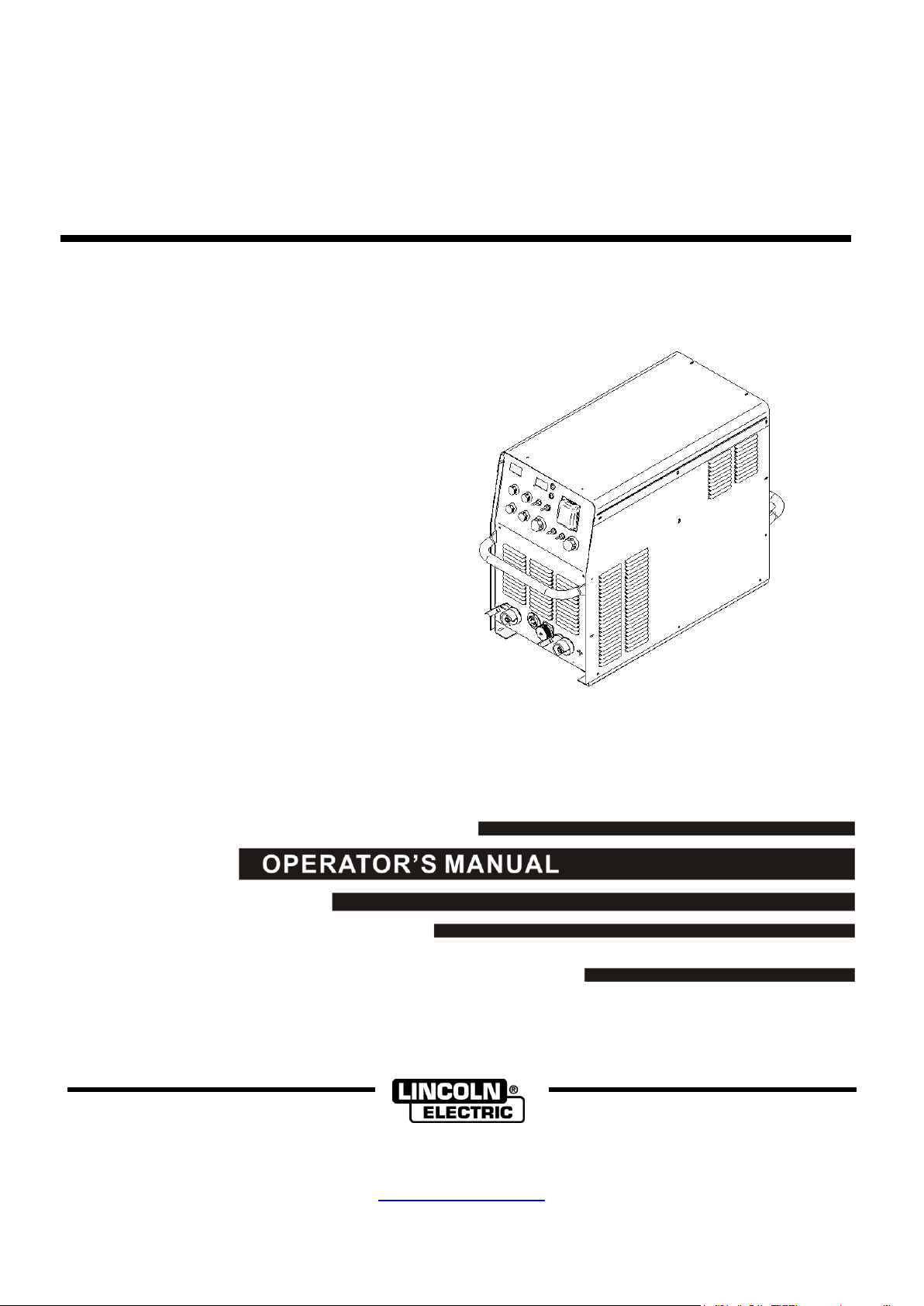
OPTIMARC
®
CV/CC500
For use with machine Part Number K60128-1, Code 76341
• World’s Leader in Welding and Cutting•
THE SHANGHAI LINCOLN ELECTRIC COMPANY
No. 195, Lane 5008, Hu Tai Rd. Baoshan, Shanghai, PRC 201907
www.lincolnelectric.com.cn
IM7025-1
Feb, 2018
Rev. 03
Rev. 03
Page 2

Thank you for selecting QUALITY Lincoln Electric products.
Please examine the packaging and equipment for damage. Claims for material damaged in shipment must be
notified immediately to the authorized dealer from whom you purchased the machine.
For future reference, please record your equipment identification information in the table below. Model Name,
Code & Serial Number can be found on the machine rating plate.
Model Name
□ OPTIMARC® CV/CC500
Code & Serial number
Date & Where Purchased
Authorized dealer’s shop
Declaration of conformity
THE SHANGHAI LINCOLN ELECTRIC COMPANY
Designed in conformance with the following norm:
GB/T 15579.1-2013
EN 60974-1
No. 195, Lane 5008, Hu Tai Rd. Baoshan, Shanghai, PRC 201907
THE SHANGHAI LINCOLN ELECTRIC COMPANY
Rev. 03
Page 3
i SAFETY i
OPTIMARC® CV/CC500
Rev. 03
Page 4
ii SAFETY ii
OPTIMARC® CV/CC500
Rev. 03
Page 5
iii SAFETY iii
OPTIMARC® CV/CC500
Rev. 03
Page 6
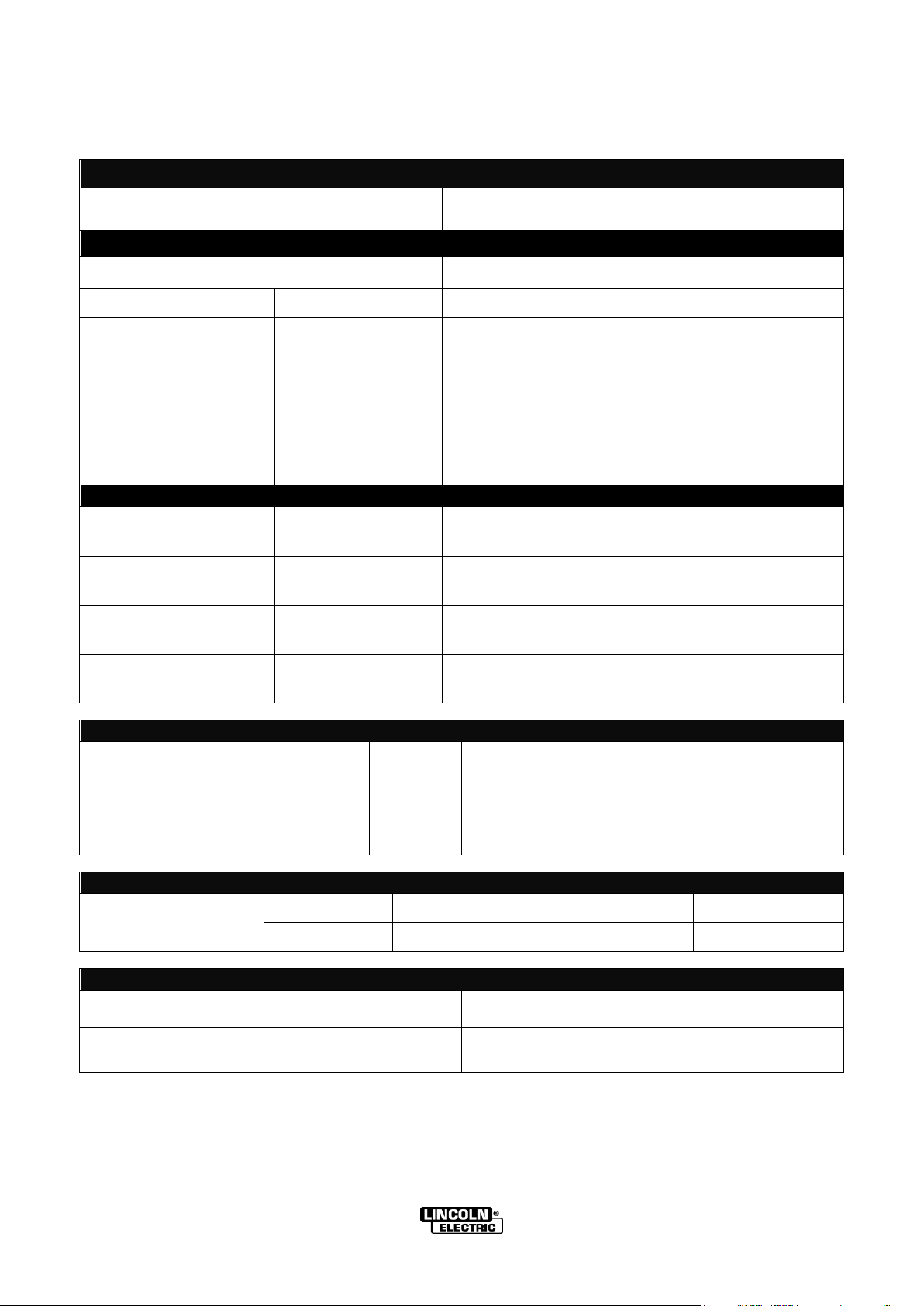
A-1 INSTALLATION A-1
INPUT – THREE PHASE ONLY
Standard Voltage / Phase / Frequency
380V ~ 415V (±10%) / 3 / 50 or 60 Hz
RATED OUTPUT – DC ONLY
Max Input Power at Rated Output ( SMAW )
23 kVA @ 60% Duty Cycle
Welding Mode
Duty Cycle
Amperes
Volts at Rated Amperes
GMAW
60%
100%
500A
390A
39V
33.5V
SMAW ( STICK )
60%
100%
500A
390A
40V
35.6V
GTAW ( TIG )
60%
100%
500A
390A
30V
25.6V
OUTPUT RANGE
Welding Mode
Welding Current Range
Open Circuit Voltage
Welding Voltage Range
GMAW
50A ~ 500A
60V
16 V ~ 39V
SMAW ( STICK )
15A ~ 500A
60V
20.6 V ~ 40V
GTAW ( TIG )
5A ~ 500A
60V
10.2 V ~ 30V
RECOMMENDED INPUT WIRE AND FUSE SIZES
OPTIMARC® CV/CC500
Input Voltage/
Frequency
(Hz)
380~415 V/
50Hz or 60Hz
Maximum
Input
Ampere
51A
Maximum
Effective
Supply
Current
40A
60°C Copper
Wire in
Conduct
Sizes
12mm2
Fuse or
Breaker Size
(Super Lag)
60A
Grounding
Conductor
Size
10mm2
PHYSICAL DIMENSIONS
OPTIMARC® CV/CC500
Height
Width
Depth
Weight
540mm
340mm
800mm
47Kg
TEMPERATURE RANGE
Operating Temperature Range
-10°C ~ +40°C
Storage Temperature Range
-25°C ~ +55°C
TECHNICAL SPECIFICATIONS – OPTIMARC® CV/CC500
For any maintenance or repair operation it is recommended to contact the nearest technical service center or directly
consult machine division of the Shanghai Lincoln Electric. Maintenance or repairs performed by unauthorized service
center or personnel will void the manufacturer’s warranty.
OPTIMARC® CV/CC500
Rev. 03
Page 7

A-2 INSTALLATION A-2
WARNING
CAUTION
WARNING
FIGURE A.1
SAFETY PRECAUTIONS
Read the entire installation section before starting
installation.
INPUT POWER AND GROUNDING
ELECTRIC SHOCK can kill.
Only qualified personnel
should perform this
installation.
Turn the input power OFF at
the main switch or fuse box
before working on this equipment. Turn off the
input power to any other equipment connected to
the welding system at the main switch or fuse
box before working on the equipment.
Do not touch electrically “Hot” parts.
Always connect the OPTIMARC® grounding lug
(located at the rear of the case) to a proper safety
(Earth) ground.
SELECT SUITABLE LOCATION
This power source should not be subjected to falling
water, nor should any parts of it be submerged in water.
Doing so may cause improper operation as well as
pose a safety hazard. The best practice is to keep the
machine in a dry, sheltered area.
CONNECTION
Only a qualified electrician should connect the
input leads to the OPTIMARC®. Connections
should be made in accordance with the connection
diagram. Failure to do so may result in bodily injury
or death.
Open the input box on the rear of the case. Use a
three-phase supply line, the three live wires should go
through the three holes of the input wire holder and be
securely clamped and fixed. Connect L1, L2, L3 and
ground according to the Input Supply Connection
Diagram decal, refer to Figure A.1 on this page.
Make sure the amount of power available from the input
connection is adequate for normal operation of the
machine. Refer to the Technical Specifications at the
beginning of this Installation section for recommended
fuse and wire sizes.
The bottom of machine must always be placed on a
firm, secure, level surface. There is a danger of the
machine toppling over if this precaution is not
taken.
Place the welder where clean cooling air can freely
circulate in through the back louvers and out through
the case sides. Water,dirt, dust or any foreign material
that can be drawn into the welder should be kept to a
minimum. Failure to observe these precautions can
result in excessive operating temperatures and
nuisance shutdowns.
Locate the OPTIMARC® machine away from radio
controlled machinery. Normal operation of the welder
may adversely affect the operation of RF controlled
equipment, which may result in bodily injury or damage
to the equipment.
STACKING
The OPTIMARC® machine can not be stacked. Be
sure to locate the machines on a firm level surface.
LIFTING
The OPTIMARC® machine can be moved using the
handles .
OPTIMARC® CV/CC500
Rev. 03
Page 8

A-3 INSTALLATION A-3
Current (60% Duty Cycle)
Minimum Copper
Work Cable Size
200A
300A
400A
500A
Up To 30m Length
30 mm2
50 mm2
70 mm
2
95 mm
2
WARNING
PROCESS SELECTIONS AND
CONNECTIONS
ELECTRIC SHOCK can kill.
Only qualified personnel
should perform this
installation.
Turn the input power OFF at
the main switch or fuse box before working on
this equipment. Turn off the input power to any
other equipment connected to the welding
system at the main switch or fuse box before
working on the equipment.
Do not touch electrically “Hot” parts.
Always connect the OPTIMARC® grounding lug
(located at the rear of the case) to a proper safety
(Earth) ground.
WORK CONNECTION
Connect a work lead of sufficient size between the
proper output stud on the power source and the work.
Be sure the connection to the work makes tight metal to
metal electrical contact. Poor work lead connections
can result in poor welding performance.
To avoid interference problems with other equipment
and to achieve the best possible operation, route all
cables directly to the work and wire feeder. Avoid
excessive lengths and do not coil excess cable.
Cable sizes are increased for greater lengths primarily
for the purpose of minimizing cable drop.
Minimum work and electrode cable sizes are as follows:
TABLE A.1
Note: The recommended cable size may need to
change depending on its quality. When the rated
current flow goes through, the total voltage drop on
ground cable and electrode cable must not exceed 4
volts.
GMAW PROCESS ( CV MODE ) WIRE FEEDER CONNECTION
1. LWF WIRE FEEDER ( FIGURE A.2 )
Set the rotary switch to FCAW-GS mode or GMAW mode;
Set the control switch to Feeder
FIGURE A.2
OPTIMARC® CV/CC500
Rev. 03
Page 9

A-4 INSTALLATION A-4
Items
Modes
Controls
Wire feeders
Voltage control
WFS/Current
control
Remote
control box
Polarity
connections
1
OPTIONAL
(Default
FCAW-SS)
Local
LN-25 Pro
Front panel of
CV/CC500
LN-25 Pro
DCEN
2
Feeder
LN-25 Pro
Remote
control box
K60030-8M/15M/-30M
3
FCAW-GS
Local
LN-25 Pro
Front panel of
CV/CC500
DCEP
4
Feeder
LWF-22
LWF-24 PLUS
LWF-22 / LWF-24 PLUS
5
GMAW
Local
LN-25 Pro
Front panel of
CV/CC500
LN-25 Pro
6 Feeder
LWF-22
LWF-24 PLUS
LWF-22 / LWF-24 PLUS
2. LN-25 PRO FEEDER ( FIGURE A.3 )
Remote control methods
Set the rotary switch to OPTIONAL (Default FCAW-SS);
Set the control switch to Feeder;
The remote control box with order part numbers K60030-8M/-15M/-30M should be used to control the machine output
and set the voltage, Use the wire feed speed pot on LN-25 to set the current.
FIGURE A.3
Local control methods
Set the rotary switch to OPTIONAL / FCAW-GS or GMAW;
Set the control switch to Local;
A summary list for all of wire feeders connections and controls
OPTIMARC® CV/CC500
Rev. 03
Page 10

A-5 INSTALLATION A-5
The actual output current would be set by the remote device up to the maximum current set by local output pot.
Note: When the machine set to 4 step, turning the crater current and voltage, the crater value will be shown on the
display, then change back to the weld preser value.
TIG torch with handle switch can be used while the switch connect correctly to the remote connector.
3. GTAW PROCESS ( CC MODE ) CONNECTION ( FIGURE A.4 )
Set the rotary switch to GTAW mode;
Set the control switch to REMOTE
Recommended to use Foot Amptrol K870.
Set the control switch to LOCAL
Machine output the maximum current set by local output pot
FIGURE A.4
4. SMAW PROCESS ( CC MODE ) CONNECTION ( FIGURE A.5 )
Set the rotary switch to SMAW mode;
Set the control switch REMOTE;
Max. output will be limited by panel output set, display always shows remote setpoint.
Set the control switch LOCAL;
Max. output current can be setted by panel output pot, arc force can be setted by arc control.
FIGURE A.5
OPTIMARC® CV/CC500
Rev. 03
Page 11

A-6 INSTALLATION A-6
TABLE A.2
Power Source
Wire Feeder
Pin
Function
Lead #
Pin
Function
Lead #
1
“ + ” pulse signal for motor control.
91
1 Positive terminal of motor.
91
2
“ + ” pulse signal for gas solenoid.
92
2
Connected to one lead of gas
solenoid.
92
3
“ + ” control signal for gas purge, cold
inch and trigger.
93
3
Control signals output ( gas purge,
cold inch and trigger ).
93
4
+/- 10V control signal for arc current
and arc voltage.
94
4
Control signals output (arc current
and arc voltage ).
94
5
GND for arc current, arc voltage, gas
purge, cold inch and trigger control.
95
5
Common GND.
95
6
GND for gas solenoid and motor
control.
96
6
Negative terminal of motor; and
connected to another lead of gas
solenoid.
96
CAUTION
A
B
C
D
E
F
FIGURE A.6 FIGURE A.7
TABLE A.3
Power Source
Remote Controller
Pin
Function
Lead #
Pin
Function
Lead #
A
Output control power +
77
A
Pot foot 1
77
B
Output control signal
76
B
Pot foot 2
76 C Output control power -
75
C
Pot foot 3
75 D Output control switch +
2 D
Switch foot 1
2 E Output control switch -
4 E
Switch foot 2
4
F
Ground lead ( case )
G2
F
Case
G2
6-PIN AMPHENOL CONNECTOR INSTRUCTION
For secure electrical connection, the screws
connecting the output terminals and cables must
be tightened. Damage may occur to the output stud
or welding performance maybe compromised.
6-PIN LWF WIRE FEEDER CONNECTOR
INSTRUCTION
Please see FIGURE A.6 and TABLE A.2 for more
details.
Please see FIGURE A.7 and TABLE A.3 for more
details.
SAFETY PRECAUTIONS
Read this entire section of operating instructions before operating the machine.
OPTIMARC® CV/CC500
Rev. 03
Page 12

A-7 INSTALLATION A-7
Weld for 6 minutes
Break for 4 minutes
WARNING
ELECTRIC SHOCK can kill.
Do not touch electrically live
parts or electrode with skin or
wet clothing.
Insulate yourself from work
and ground.
Always wear dry insulating gloves.
FUMES AND GASES can be
dangerous.
Keep your head out of fumes.
Use ventilation or exhaust to
remove fumes from breathing
zone.
WELDING SPARKS can cause
fire or explosion.
Keep flammable material away.
Do not weld on closed
containers.
ARC RAYS can burn eyes and
skin.
Wear eye, ear and body
protection.
PLEASE SEE ADDITIONAL
WARNING INFORMATION AT THE FRONT OF
THIS OPERATOR’S MANUAL
DUTY CYCLE
The duty cycle of a welding machine is the percentage
of time in a 10 minute cycle at which the welder can
operate the machine at rated welding current.
60% duty cycle:
Excessive extension of the duty cycle will cause the
thermal protection circuit to activate.
THERMAL PROTECTION
The OPTIMARC® machine is equipped with a thermal
protection device. When the machine has gone into
thermal overload, the output will be turned off and the
thermal indicator light will be turned “ON“. When the
machine has cooled to a safe temperature, the Thermal
Indicator Light will go out and the machine may resume
normal operation.
Note: For safety reasons the machine’s welding output
will not come on after a thermal shutdown until the
output is disabled and re-enabled.
OPTIMARC® CV/CC500
Rev. 03
Page 13

B-3 OPERATION B-3
OPERATIONAL FEATURES AND
CONTROLS
FRONT PANEL (SEE FIGURE B.1)
1. GAS SELECTION
OPTIMARC® CV/CC500 is designed for CO2 and
Ar/CO2.
2. WELDING MODE SELECTION
OPTIMARC® CV/CC500 includes 5 following modes:
OPTIONAL.
A default procedure is for self-shielded flux
cored wire arc welding.
FCAW-GS.
It is for gas shielded flux cored wire arc welding.
Setting up the machine, please see the Figure
A.3
GMAW.
It is for gas shielded solid wire arc welding.
GTAW.
It is for TIG mode. OPTIMARC® CV/CC500
must apply “touch start” for arc start.
SMAW.
It is for stick mode.
3. WIRE DIAMETER SELECTION
OPTIMARC® CV/CC500 is designed for Φ1.0, Φ1.2
and Φ 1.6 wires.
4. ON/OFF POWER SWITCH
Switch up to power on; Switch down to power off.
5. CONTROL SWITCH
LOCAL
When switch to local,the output current or output
voltage can be setted by output control knob (See
item 15).
FEEDER
When switch to feeder,the welding current and
voltage can be setted by the feeder knob in GMAW
mode (See item 19).
REMOTE
When switch to remote,the welding current or
voltage can be setted by a remote control box,
choose the right connector according to the weld
mode (See item 18).
6. THERMAL INDICATOR
This status light illuminates when the power source has
been driven into thermal overload. The indicator light
also momentarily turns on during start up.
7. 2-STEP AND 4-STEP SELECTION
This toggle switch enables the selection of 2-STEP or
4-STEP operation mode without or with crater function.
2-STEP mode - no crater output after user release the
trigger. 4-STEP mode – crater function initiates when
uses “Clicks” trigger again after releasing it. Please
see FIGURE B.3 and B.4 to know the more details of
time sequence of OPTIMARC® CV/CC 500.
8. DIGITAL INDICATION VOLTAGE METER
This meter displays the preset voltage before a weld
and the actual voltage during a weld . The actual
voltage is displayed for 5 seconds after a weld ends.
During this time the display flash.
9. SYNERGIC
This status light illuminates when the power source is
set for synergic operation. Synergic operation is
controlled by DIP switch 5 on the control board. See
the DIP switch section for additional information.
10. DIGITAL INDICATION CURRENT METER
This meter displays the preset current before a weld
and theactual welding current during a weld. The
actual current is displayed for 5 seconds after a weld
ends. During this time the display falsh.
11. CRATER VOLTAGE
This knob sets the value of output voltage during the
crater time.
12. CRATER CURRENT
This knob sets the value of output current (wire
feeding speed) during the crater time.
13. HOT START
This knob can be used for setting the additional output
value at the start of weld in all of modes.
14. ARC CONTROL
This knob control the arc output characteristic. When
it is turned clockwise, the arc is crisper. When it
turned counter clockwise,the arc is softer.
15. LOCAL OUTPUT CONTROL
When item 9 is set to “LOCAL”, The output voltage
( CV mode ) or output current ( CC mode ) will be
controlled by this knob.
In TIG mode, it will control the maximum output
current.
In stick mode, it will limited the output current range.
16. NEGATIVE OUTPUT STUD
17. POSITIVE OUTPUT STUD
18. 6-PIN AMPHENOL CONNECTOR
Please see the FIGURE A.7 for the details of the
connection. Recommend the standard remote
controller for GTAW mode is K870 ( Foot amptrol );
and standard remote controller for SMAW is K857
( Pot control ).
19. 6-PIN LWF WIRE FEEDER CONNECTOR
Please see the FIGURE A.6 for the details of the
connection.
20. STATUS INDICATOR
The status light will be green for normal operation;
while the status light will flash in red with a serial of
error digital codes as power source gets in some
trouble. The status light will always have
synchronization with the LED3 on switchboard inside
machine.
OPTIMARC® CV/CC500
Rev. 03
Page 14

B-3 OPERATION B-3
1
2
3
4
5
6
7
8
9
10
11
12
13
14
15
16
17
18
19
20
21
22
23
24
25
26
WARNING
CAUTION
REAR PANEL (PLEASE SEE FIGURE B.2).
21. INPUT CABLE HOLDING BRACKET
24. AUX. VOLTAGE RECEPTACLE
Export type machine: This is a 220V 200W max.
auxiliary power output socket, for plugging gas heater.
This bracket securely holds the three phase power cables
in place.
22. INPUT BOX
This insulation box is used to cover the input
connections.
This insulation box must be secure before turning on
the main power supply.
23. GROUND LEAD CONNECTION
Connect the ground lead to the paint-free location on
the case back by securing its lug-end with the screw
into the case hole.
Only Plug the correct gas heater into this receptacle.
DO NOT plug other electric devices into the
receptacle, otherwise damage may occur to the
OPTIMARC® machine.
25. FUSE AND FUSE HOLDER
Export type machine: 250V 2A fuse is used to protect
the auxiliary 220V power outlet
26. FUSE AND FUSE HOLDER
250V 8A fuse is used to protect the auxiliary power for
the wire feeder.
Figure B.1 Figure B.2
OPTIMARC® CV/CC500
Rev. 03
Page 15

B-3 OPERATION B-3
Trigger Open
Closed
Open
Closed
Shielding Gas
Preflow Time
Welding Voltage
OCV
Wire Feeder Speed
Run-in
Welding Current
Burn Back
Burn Back
FIGURE B.3
Trigger Open
Closed
Open
Closed
Shielding Gas
Preflow Time
Welding Voltage
OCV
Wire Feeder Speed
Run-in
Welding Current
Burn Back
Burn Back
Crater Voltage
Crater Current
Crater Status
Crater Status
FIGURE B.4
Trigger Open
Closed
Open
Closed
Shielded Gas
Preflow Time
Welding Voltage
OCV
Wire Feeder Speed
Run-in
Welding Current
Burn Back
Within 2 seconds
Crater Voltage
Crater Current
Crater Status
Crater Status
Crater
Current
Burn Back
Crater
Voltage
Open
Closed
Repeat Crater Status
FIGURE B.5
OPTIMARC® CV/CC500
Rev. 03
Page 16

B-4 OPERATION B-4
WARNING
DIP switch
continue output at crater voltage and current to fill this
DIP SWITCH DESCRIPTIONS
OPTIMARC® CV/CC machine offers a DIP switch on
the control board, which allows user to have additional
features. After disconnecting the machine from input
power remove the roof To set the DIP switch。
Disconnecting the machine,
before the roof removed.
See FIGURE B.7 for the right position.
There are 8 individual switches integrated into this
DIP switch .All the initial factory settings in the OFF
position. Please see FIGURE B.6.
1. PREFLOW ON/OFF SWITCH
This switch enables preflow before turning on output
voltage. Please see FIGURE B.3 for detail.
2. LONG CABLE WELD MODE SWITCH
OFF = welding with a cable length less than 20M.
ON = welding with a cable length more than 20M
(including 20M).
3. CRATER REPEAT MODE SWITCH
Should the operator find a visible crater appearing
after releasing the trigger, and within 2 seconds,
activating the trigger again the power source will
FIGURE B.6 FIGURE B.7
crater. For more details, please see FIGURE B.5.
4. SPECIAL FUNCTION TEST
It enables a test procedure to test the control knobs
and the toggle switches, when the DIP switch 4 is ON
and the other DIP switches are OFF. The DIP switch
should be OFF when user prepares to weld.
5. SYNERGIC
OFF = Amps and volts knobs on feeder are
independent
ON = Preset of volts knob is tied to the preset of the
amps knob.
Preset a current first , then set the voltage to match
the current, as 200A, 25V, then the voltage will follow
the current as machine programmed when the current
adjusted.
See operation feature item 8.
6. FAST RUN-IN
OFF = run-in is 35% of weld set wire feed speed
(limited by the absolute wire feed speed minimum set
in the parameter file)
ON = run-in is 75% of weld set wire feed speed
(limited by the absolute wire feed speed minimum set
in the parameter file)
7. FEEDER APPLICATION
OFF = 18.3V wire feeder application.
ON = 24V wire feeder application.
8. WIRE FEEDER SPEED CALIBRATION.
OPTIMARC® CV/CC500
Rev. 03
Page 17

C-1 TROUBLESHOOTING C-1
CAUTION
If for any reason you do not understand the test procedures or are unable to
perform the tests/repairs safely, contact your local authorized Lincoln Electric
Field Service Facility for technical assistance.
Observe all Safety Guidelines detailed in the beginning and throughout this manual.
Problems (Symptoms)
Possible Areas of Misadjustment(s)
Recommended Course of Action
Output Problems
Major physical or
electrical damage is
evident when the sheet
metal covers are
removed.
None
Contact your local
authorized Lincoln Electric
Field Service facility for
technical assistance.
Machine will not power up
(no lights, no fan, etc.)
1. Make certain that the power to the
OPTIMARC® CV/CC500 is energized and is
within the OPTIMARC® CV/CC500’s
operating range.
In a typical installation the
main power switch on the
controller is the power
switch.
Thermal LED is lit.
1. Check for proper fan operation. (Fan
should run whenever output power is on.)
Check for material blocking intake or
exhaust louvers, or for excessive dirt
clogging cooling channels in machine.
2. Machine may have been operated above
it’s duty cycle..
3.
Clear obstruction or repair
fan
After machine has cooled,
reduce load, duty cycle, or
both
Machine won’t weld, can’t
get any output.
1. Input voltage is too low or too high. Make
certain that input voltage is proper,
according to the Rating Plate.
2. If the Thermal LED is also lit, see Thermal
LED is Lit section.
3. If an error code is also present.
4. Make sure the terminal switch is ON.
Contact your local
authorized Lincoln Electric
Field Service facility for
technical assistance.
Machine won’t produce
full output.
1. Input voltage may be too low, limiting
output capability of the power source.
Make certain that the input voltage is
proper, according to the Rating Plate.
2. Secondary current or voltage is not
properly calibrated.
Correct input voltage level.
Contact your local
authorized Lincoln Electric
Field Service facility for
technical assistance.
Machine often “noodle”
welds (output is limited to
approximately 100 amps)
Secondary current limit has been exceeded,
and the machine has phased back to protect
itself.
Adjust procedure or reduce load
to lower current draw from the
machine.
General degradation of
the weld performance
1. Check for feeding problems, bad
connections, excessive loops in
cabling, etc.
2. Verify weld mode is correct for processes.
3. The power source may require calibration.
4.
If the machine need calibration,
contact an authorized Lincoln
Electric Service facility for
technical assistance.
The 4-step mode is not
available
1. Verify the CRATER ON/OFF toggle switch on
the front panel of machine is at ON position.
2. Verify the parameter of crater current and
voltage are set properly.
3. PC board in machine possibily at fault.
If PC board in machine is at
fault, contact an authorized
Lincoln Electric Service facility
for technical assistance.
The welding arc is not stable
and soft.
1. Verify the proper polarity is being used for the
weld procedure.
2. Check all electrode and work connections.
3. Verify the parameters of wire feeding speed,
output voltage and shielding gas are proper for
the welding procedure.
4. PC board in machine possibily at fault.
If PC board in machine is at
fault, contact an authorized
Lincoln Electric Service facility
for technical assistance.
OPTIMARC® CV/CC500
Rev. 03
Page 18

C-2 TROUBLESHOOTING C-2
CAUTION
If for any reason you do not understand the test procedures or are unable to
perform the tests/repairs safely, contact your local authorized Lincoln Electric
Field Service Facility for technical assistance.
Observe all Safety Guidelines detailed in the beginning and throughout this manual.
Problems (Symptoms)
Possible Areas of Misadjustment(s)
Recommended Course of Action
Starting arc is difficult.
1. Verify the proper polarity is being used for the
weld procedure.
2. Check all electrode and work connections.
3. Verify the parameters of wire feeding speed,
output voltage and shielding gas are proper for
the welding procedure.
4. PC board in machine possibily at fault.
If PC board in machine is at
fault, contact an authorized
Lincoln Electric Service facility
for technical assistance.
The meter displays ERR 031
Primary over current from switchboard.
Contact your local
authorized Lincoln Electric
Field Service facility for
technical assistance.
The meter displays ERR 032
Low input line voltage error from control board.
Contact your local
authorized Lincoln Electric
Field Service facility for
technical assistance.
The meter displays ERR 035
Input voltage out of range.
Make certain that input
voltage is proper, according
to the Rating Plate.
The meter displays ERR 036
Thermostat Trip.
Clear obstruction or repair
fan;
After machine has cooled,
reduce load, duty cycle, or
both.
The meter displays ERR 041
Secondary over current from switchboard
Contact your local
authorized Lincoln Electric
Field Service facility for
technical assistance.
The meter displays ERR 082
Motor overload.
Please reduce the welding duty
cycle of machine.
The meter displays ERR 124
Invalid weld mode.
Please check if all the welding
procedures are correct.
The meter displays ERR 213
CAN communication error.
Contact your local
authorized Lincoln Electric
Field Service facility for
technical assistance.
OPTIMARC® CV/CC500
Rev. 03
Page 19

D-1 D I A G R A M D-1
STATUS
LED
R
G5964-43
A.02
_
26A
27 25A
+
OUTPUT CHOCK
L1
AC 220V
RECEPTACLE
SHUNT
600A 60mV
SWITCH
29
27 28
SWITCH
BOARD
-5
+
4
L3
L2
L1
223
221
RECTIFIER
26
+
-2683
82
4
220C
221C
30 OHM
200 W
220B
221B
21
20
19
21A
29A
207
209
223
221
33
34
283
284
J21-1
J21-4
201
204
2
1
209 207
220A
J21-6
J27-1
J27-2
207
209
J2
3-
1
J2
3-
2
19
20
21
X2
X4
1
~
2
~
3
~
+
-
+
-
H
L
FAN
U
N
B
G
INPUT
RECTIFIER
FUSE
2A/250V
U
V
W
CASE BACK
FRAME
W V
U
L3
L2
L1
G1
X1
MAIN
TRANSFORMER
X4
1
2
X2
X3
OUTPUT
RECTIFIER
220A
1
2
~380V
6
7
AUXILIARY
TRANSFORMER
4
5
~36V 3A
~220V 1A
20A
29
28
RECTIFIER
-
+
34
33
9
8
33
8
9
~36V 0.5A
258
265
91
92
93
J1-8
J5-1
J5-2
J5-3
J5-4
J5-5
J4-4
J4-3
J4-5
258
264
91
92
93
J2-8
J5-6
83
82
J6-3
J6-5
J6-2
J6-4
J6-1
283
284
265
264
WIRE SIZE
1.2
ARC CONTROL
J10-4
J10-5
J10-7
J10-6
J10-8
DISPLAY
BOARD
271
274
272
273
275
DATA
CLOCK
ENABLE
+15V
MOTOR
GAS SOLENOI
D
2.5K
10
K
GAS
PURGE
COLD
INCH
TRIGGER
91
92
94
93
96
95
<1<
<2<
<3<
<4<
<5<
<6<
WIRE FEEDER
CONNECTOR
GSA/MOTOR
POT/SWITCH
+/-10V
+15V
+24V
+50V
BLAKE
19.5KHZ
DRIVE
S1
1 2 3 4 5 6 7 8
ON
CONTROL BOARD
xx
xx
xx
x
ARC VOLTS
5K
ARC CURRENT
5K
4.7K
266
266
+15V
J2-7
CRATER VOLTAGE
HOT START
10 KOhm
10 KOhm
10 KOhm
J2-4
224
288
225
255
91
93
94
95
96
J7-4J7
-3
J7
-1
J7
-2
H
L
+50V
+15V
93B
93A
95A
95B
OPTIMARC CV/CC500 WIRING SCHEMATIC
20C
POSITIVE
NEGATIVE
1.0
1.6
5P ROTARY SWITCH
J3-1
OPTIONAL
J3-3
J3-2
GMAW
293
292
291
293
292
291
FCAW-GS
J3-7
296
296
J2-6
256
J2-9
259C
J20-13
J20-5
258258258258258268
267
CLOSED= 4 STEP
257
J4-1
257
J4-2
257
260
261
CLOSED = CO2/Ar
J1-9
221A
220A
221A
J21-3
21A
20A
B
B
21B
20B
288
254A
256
259A
254A
256
259A
258
257
258
257
257257257
260
261
260
261
258258258258258258258
268
267
258258258258258258258268
267
VIEW OF CONNECTOR ON PCB
ELECTRICAL SYMBOLS PER E1537
OHMS/WATTS
RESISTORS:
MFD/VO LTS
CAPACITORS:
8
LATCH
EXAMPLE: PIN 7 OF
CONNECTOR J5
32
LEAD COLORING CODE:
B-BLACK
21
8
G-GREEN
O-ORANGE
R-RED
CONNECTOR PIN
NUMBER:
7
14
U-BLUE
Y-YELLOW
W-WHITE
1
3
J5
N-BROWN
ALL COMPONENTS VIEWED FROM REAR.
FERRITE
BEAD
SPIKE
BLOCKER
G
1) ON = PREFLOW
2) ON = LONG CABLE WELD MODE
3) ON = CRATER REPLS MODE
4) ON = TEST MODE
5) ON = SYNERGIC
6) ON = FAST RUN-IN
7) ON = 24VWIRE FEEDER APPLICATION
8) ON = WIRE FEED SPEED CALIBRATION
THERMAL
LED
J20-12
J20-4
+15V
227
226
259B
254C
254B
xx
xx
xx
x
THER
MOSTAT
#2
228
225A
21A
20B
21B
COMPONENT
VALUE UNITE:
THER
MOSTAT
#1
FERRITE
BEAD
FERRITE
BEAD
SPIKE
BLOCKER
LOCAL OUTPUT
CONTROL
10 KOhm
J2-1
288
J2-2
256
J2-3
288
251
252
253
288
251
252
253
J2-5
CRATER CURRENT
10 KOhm
259D
255
255
254D
J4-7
J4-8
J4-6
262
269
FEEDER
263
LOCAL
REMOTE
262
269
263
J3-4GTAW
J3-5
295
294
295
294
SMAW
A
B
C
D
E
F 77
76
75
76
77
J1-3
J1-2
J1-1
2G24
FUSE
8A/250V
26
25
25
232
231
J20-6
J20-14
+15V
OUTPT
INPUT
NOTE: This diagram is for reference only. It may not be accurate for all machines coved by this manual. The specific diagram for a particular code is pasted inside the machine on one of the enclosure panels. If the diagram is illegible,
contact the Lincoln Electric Service Department for a replacement
OPTIMARC® CV/CC500
Rev. 03
Page 20

E-1 BOTTOM E-1
• World’s Leader in Welding and Cutting•
THE SHANGHAI LINCOLN ELECTRIC COMPANY
No. 195, Lane 5008, Hu Tai Rd. Baoshan, Shanghai, PRC 201907
www.lincolnelectric.com.cn
OPTIMARC® CV/CC500
Rev. 03
 Loading...