

Page 1
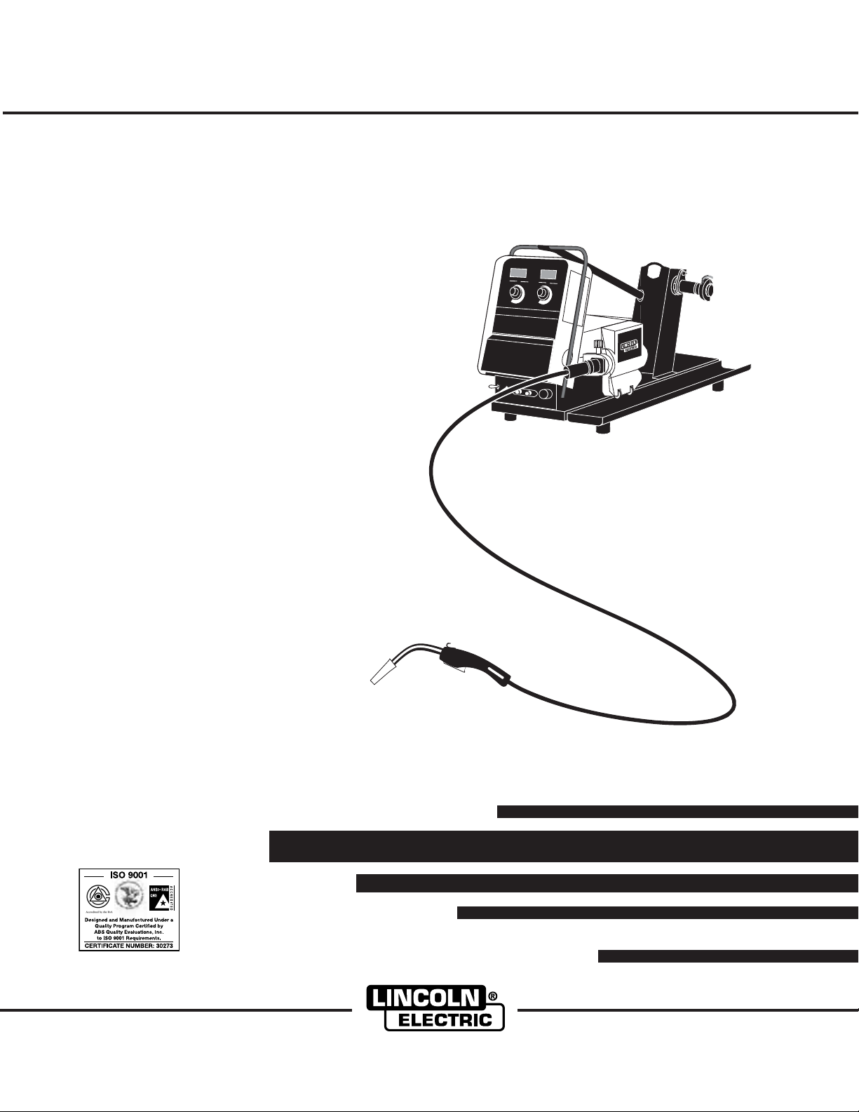
Power Feed 10 Wire Drive & Control Box
Power Feed 10 Control Box - Boom Mount Code 10436, 10615
Power Feed 10 Wire Drive - Boom Mount Code 10437,10616, 10782
Power Feed 10 Boom Package Code 10435, 10612 (Generic), 10493, 10613 (12’ Zipline), 10494, 10614 (16’ Zipline),
10779 (Generic), 10767, 10780 (12’ Zipline), 10768, 10781 (16’ Zipline)
Power Feed 10 Bench Model Code 10438, 10617, 10760,10783
RETURN TO MAIN MENU
Boom Mount or Bench Model
IM584-D
August, 2007
For use with:
Safety Depends on You
Lincoln arc welding and cutting
equipment is designed and built
with safety in mind. However, your
overall safety can be increased by
proper installation ... and thoughtful operation on your part. DO
NOT INSTALL, OPERATE OR
REPAIR THIS EQUIPMENT
WITHOUT READING THIS
MANUAL AND THE SAFETY
PRECAUTIONS CONTAINED
THROUGHOUT. And, most
importantly, think before you act
and be careful.
Cleveland, Ohio 44117-1199 U.S.A. TEL: 216.481.8100 FAX: 216.486.1751 WEB SITE: www.lincolnelectric.com
OPERATOR’S MANUAL
Copyright © 2007 Lincoln Global Inc.
• World's Leader in Welding and Cutting Products •
• Sales and Service through Subsidiaries and Distributors Worldwide •
Page 2
i
SAFETY
i
WARNING
CALIFORNIA PROPOSITION 65 WARNINGS
Diesel engine exhaust and some of its constituents
are known to the State of California to cause cancer, birth defects, and other reproductive harm.
The Above For Diesel Engines
ARC WELDING CAN BE HAZARDOUS. PROTECT YOURSELF AND OTHERS FROM POSSIBLE SERIOUS INJURY OR DEATH.
KEEP CHILDREN AWAY. PACEMAKER WEARERS SHOULD CONSULT WITH THEIR DOCTOR BEFORE OPERATING.
Read and understand the following safety highlights. For additional safety information, it is strongly recommended that you
purchase a copy of “Safety in Welding & Cutting - ANSI Standard Z49.1” from the American Welding Society, P.O. Box
351040, Miami, Florida 33135 or CSA Standard W117.2-1974. A Free copy of “Arc Welding Safety” booklet E205 is available
from the Lincoln Electric Company, 22801 St. Clair Avenue, Cleveland, Ohio 44117-1199.
BE SURE THAT ALL INSTALLATION, OPERATION, MAINTENANCE AND REPAIR PROCEDURES ARE
PERFORMED ONLY BY QUALIFIED INDIVIDUALS.
The engine exhaust from this product contains
chemicals known to the State of California to cause
cancer, birth defects, or other reproductive harm.
The Above For Gasoline Engines
FOR ENGINE
powered equipment.
1.a. Turn the engine off before troubleshooting and maintenance
work unless the maintenance work requires it to be running.
____________________________________________________
1.b. Operate engines in open, well-ventilated
areas or vent the engine exhaust fumes
outdoors.
____________________________________________________
1.c. Do not add the fuel near an open flame
welding arc or when the engine is running.
Stop the engine and allow it to cool before
refueling to prevent spilled fuel from vaporizing on contact with hot engine parts and
igniting. Do not spill fuel when filling tank. If
fuel is spilled, wipe it up and do not start
engine until fumes have been eliminated.
____________________________________________________
1.d. Keep all equipment safety guards, covers and devices in
position and in good repair.Keep hands, hair, clothing and
tools away from V-belts, gears, fans and all other moving
parts when starting, operating or repairing equipment.
____________________________________________________
1.e. In some cases it may be necessary to remove safety
guards to perform required maintenance. Remove
guards only when necessary and replace them when the
maintenance requiring their removal is complete.
Always use the greatest care when working near moving
parts.
___________________________________________________
1.f. Do not put your hands near the engine fan.
Do not attempt to override the governor or
idler by pushing on the throttle control rods
while the engine is running.
1.h. To avoid scalding, do not remove the
radiator pressure cap when the engine is
hot.
ELECTRIC AND
MAGNETIC FIELDS
may be dangerous
2.a. Electric current flowing through any conductor causes
localized Electric and Magnetic Fields (EMF). Welding
current creates EMF fields around welding cables and
welding machines
2.b. EMF fields may interfere with some pacemakers, and
welders having a pacemaker should consult their physician
before welding.
2.c. Exposure to EMF fields in welding may have other health
effects which are now not known.
2.d. All welders should use the following procedures in order to
minimize exposure to EMF fields from the welding circuit:
2.d.1.
Route the electrode and work cables together - Secure
them with tape when possible.
2.d.2.Never coil the electrode lead around your body.
2.d.3. Do not place your body between the electrode and
work cables. If the electrode cable is on your right
side, the work cable should also be on your right side.
___________________________________________________
1.g. To prevent accidentally starting gasoline engines while
turning the engine or welding generator during maintenance
work, disconnect the spark plug wires, distributor cap or
magneto wire as appropriate.
2.d.4. Connect the work cable to the workpiece as close as
possible to the area being welded.
2.d.5. Do not work next to welding power source.
Mar ʻ95
Page 3
ii
SAFETY
ii
ELECTRIC SHOCK can
kill.
3.a. The electrode and work (or ground) circuits
are electrically “hot” when the welder is on.
Do not touch these “hot” parts with your bare
skin or wet clothing. Wear dry, hole-free
gloves to insulate hands.
3.b. Insulate yourself from work and ground using dry insulation.
Make certain the insulation is large enough to cover your full
area of physical contact with work and ground.
In addition to the normal safety precautions, if welding
must be performed under electrically hazardous
conditions (in damp locations or while wearing wet
clothing; on metal structures such as floors, gratings or
scaffolds; when in cramped positions such as sitting,
kneeling or lying, if there is a high risk of unavoidable or
accidental contact with the workpiece or ground) use
the following equipment:
• Semiautomatic DC Constant Voltage (Wire) Welder.
• DC Manual (Stick) Welder.
• AC Welder with Reduced Voltage Control.
3.c. In semiautomatic or automatic wire welding, the electrode,
electrode reel, welding head, nozzle or semiautomatic
welding gun are also electrically “hot”.
3.d. Always be sure the work cable makes a good electrical
connection with the metal being welded. The connection
should be as close as possible to the area being welded.
3.e. Ground the work or metal to be welded to a good electrical
(earth) ground.
ARC RAYS can burn.
4.a. Use a shield with the proper filter and cover
plates to protect your eyes from sparks and
the rays of the arc when welding or observing
open arc welding. Headshield and filter lens
should conform to ANSI Z87. I standards.
4.b. Use suitable clothing made from durable flame-resistant
material to protect your skin and that of your helpers from
the arc rays.
4.c. Protect other nearby personnel with suitable, non-flammable
screening and/or warn them not to watch the arc nor expose
themselves to the arc rays or to hot spatter or metal.
FUMES AND GASES
can be dangerous.
5.a. Welding may produce fumes and gases
hazardous to health. Avoid breathing these
fumes and gases. When welding, keep
your head out of the fume. Use enough
ventilation and/or exhaust at the arc to keep
fumes and gases away from the breathing zone. When
welding with electrodes which require special
ventilation such as stainless or hard facing (see
instructions on container or MSDS) or on lead or
cadmium plated steel and other metals or coatings
which produce highly toxic fumes, keep exposure as
low as possible and below Threshold Limit Values (TLV)
using local exhaust or mechanical ventilation. In
confined spaces or in some circumstances, outdoors, a
respirator may be required. Additional precautions are
also required when welding on galvanized steel.
3.f.
Maintain the electrode holder, work clamp, welding cable and
welding machine in good, safe operating condition. Replace
damaged insulation.
3.g. Never dip the electrode in water for cooling.
3.h. Never simultaneously touch electrically “hot” parts of
electrode holders connected to two welders because voltage
between the two can be the total of the open circuit voltage
of both welders.
3.i. When working above floor level, use a safety belt to protect
yourself from a fall should you get a shock.
3.j. Also see Items 6.c. and 8.
5. b. The operation of welding fume control equipment is affected
by various factors including proper use and positioning of
the equipment, maintenance of the equipment and the specific welding procedure and application involved. Worker
exposure level should be checked upon installation and
periodically thereafter to be certain it is within applicable
OSHA PEL and ACGIH TLV limits.
5.c.
Do not weld in locations near chlorinated hydrocarbon
coming from degreasing, cleaning or spraying operations.
The heat and rays of the arc can react with solvent vapors
form phosgene, a highly toxic gas, and other irritating products.
5.d. Shielding gases used for arc welding can displace air and
cause injury or death. Always use enough ventilation,
especially in confined areas, to insure breathing air is safe.
5.e. Read and understand the manufacturerʼs instructions for this
equipment and the consumables to be used, including the
material safety data sheet (MSDS) and follow your
employerʼs safety practices. MSDS forms are available from
your welding distributor or from the manufacturer.
5.f. Also see item 1.b.
vapors
AUG 06
to
Page 4
iii
SAFETY
iii
WELDING and CUTTING
SPARKS can
cause fire or explosion.
6.a.
Remove fire hazards from the welding area.
If this is not possible, cover them to prevent
Remember that welding sparks and hot
materials from welding can easily go through small cracks
and openings to adjacent areas. Avoid welding near
hydraulic lines. Have a fire extinguisher readily available.
6.b. Where compressed gases are to be used at the job site,
special precautions should be used to prevent hazardous
situations. Refer to “Safety in Welding and Cutting” (ANSI
Standard Z49.1) and the operating information for the
equipment being used.
6.c. When not welding, make certain no part of the electrode
circuit is touching the work or ground. Accidental contact
can cause overheating and create a fire hazard.
6.d. Do not heat, cut or weld tanks, drums or containers until the
proper steps have been taken to insure that such procedures
will not cause flammable or toxic vapors from substances
inside. They can cause an explosion even
been “cleaned”. For information, purchase “Recommended
Safe Practices for the
Containers and Piping That Have Held Hazardous
Substances”, AWS F4.1 from the American Welding Society
(see address above).
6.e. Vent hollow castings or containers before heating, cutting or
welding. They may explode.
Sparks and spatter are thrown from the welding arc. Wear oil
6.f.
free protective garments such as leather gloves, heavy shirt,
cuffless trousers, high shoes and a cap over your hair. Wear
ear plugs when welding out of position or in confined places.
Always wear safety glasses with side shields when in a
welding area.
6.g. Connect the work cable to the work as close to the welding
area as practical. Work cables connected to the building
framework or other locations away from the welding area
increase the possibility of the welding current passing
through lifting chains, crane cables or other alternate circuits. This can create fire hazards or overheat lifting chains
or cables until they fail.
6.h. Also see item 1.c.
the welding sparks from starting a fire.
though
they have
Preparation
for Welding and Cutting of
CYLINDER may explode
if damaged.
7.a. Use only compressed gas cylinders
containing the correct shielding gas for the
process used and properly operating
regulators designed for the gas and
pressure used. All hoses, fittings, etc. should be suitable for
the application and maintained in good condition.
7.b. Always keep cylinders in an upright position securely
chained to an undercarriage or fixed support.
7.c. Cylinders should be located:
• Away from areas where they may be struck or subjected to
physical damage.
• A safe distance from arc welding or cutting operations and
any other source of heat, sparks, or flame.
7.d. Never allow the electrode, electrode holder or any other
electrically “hot” parts to touch a cylinder.
7.e. Keep your head and face away from the cylinder valve outlet
when opening the cylinder valve.
7.f. Valve protection caps should always be in place and hand
tight except when the cylinder is in use or connected for
use.
7.g. Read and follow the instructions on compressed gas
cylinders, associated equipment, and CGA publication P-l,
“Precautions for Safe Handling of Compressed Gases in
Cylinders,” available from the Compressed Gas Association
1235 Jefferson Davis Highway, Arlington, VA 22202.
FOR ELECTRICALLY
powered equipment.
8.a. Turn off input power using the disconnect
switch at the fuse box before working on
the equipment.
8.b. Install equipment in accordance with the U.S. National
Electrical Code, all local codes and the manufacturerʼs
recommendations.
8.c. Ground the equipment in accordance with the U.S. National
Electrical Code and the manufacturerʼs recommendations.
6.I. Read and follow NFPA 51B “ Standard for Fire Prevention
During Welding, Cutting and Other Hot Work”, available
from NFPA, 1 Batterymarch Park,PO box 9101, Quincy, Ma
022690-9101.
6.j. Do not use a welding power source for pipe thawing.
Jan, 07
Page 5

iv
SAFETY
iv
PRÉCAUTIONS DE SÛRETÉ
Pour votre propre protection lire et observer toutes les instructions
et les précautions de sûreté specifiques qui parraissent dans ce
manuel aussi bien que les précautions de sûreté générales suivantes:
Sûreté Pour Soudage A LʼArc
1. Protegez-vous contre la secousse électrique:
a. Les circuits à lʼélectrode et à la piéce sont sous tension
quand la machine à souder est en marche. Eviter toujours
tout contact entre les parties sous tension et la peau nue
ou les vétements mouillés. Porter des gants secs et sans
trous pour isoler les mains.
b. Faire trés attention de bien sʼisoler de la masse quand on
soude dans des endroits humides, ou sur un plancher
metallique ou des grilles metalliques, principalement dans
les positions assis ou couché pour lesquelles une grande
partie du corps peut être en contact avec la masse.
c. Maintenir le porte-électrode, la pince de masse, le câble
de soudage et la machine à souder en bon et sûr état
defonctionnement.
d.Ne jamais plonger le porte-électrode dans lʼeau pour le
refroidir.
e. Ne jamais toucher simultanément les parties sous tension
des porte-électrodes connectés à deux machines à souder
parce que la tension entre les deux pinces peut être le
total de la tension à vide des deux machines.
f. Si on utilise la machine à souder comme une source de
courant pour soudage semi-automatique, ces precautions
pour le porte-électrode sʼapplicuent aussi au pistolet de
soudage.
2. Dans le cas de travail au dessus du niveau du sol, se protéger
contre les chutes dans le cas ou on recoit un choc. Ne jamais
enrouler le câble-électrode autour de nʼimporte quelle partie
du corps.
5. Toujours porter des lunettes de sécurité dans la zone de
soudage. Utiliser des lunettes avec écrans lateraux dans les
zones où lʼon pique le laitier.
6. Eloigner les matériaux inflammables ou les recouvrir afin de
prévenir tout risque dʼincendie dû aux étincelles.
7. Quand on ne soude pas, poser la pince à une endroit isolé de
la masse. Un court-circuit accidental peut provoquer un
échauffement et un risque dʼincendie.
8. Sʼassurer que la masse est connectée le plus prés possible
de la zone de travail quʼil est pratique de le faire. Si on place
la masse sur la charpente de la construction ou dʼautres
endroits éloignés de la zone de travail, on augmente le risque
de voir passer le courant de soudage par les chaines de levage, câbles de grue, ou autres circuits. Cela peut provoquer
des risques dʼincendie ou dʼechauffement des chaines et des
câbles jusquʼà ce quʼils se rompent.
9. Assurer une ventilation suffisante dans la zone de soudage.
Ceci est particuliérement important pour le soudage de tôles
galvanisées plombées, ou cadmiées ou tout autre métal qui
produit des fumeés toxiques.
10. Ne pas souder en présence de vapeurs de chlore provenant
dʼopérations de dégraissage, nettoyage ou pistolage. La
chaleur ou les rayons de lʼarc peuvent réagir avec les vapeurs
du solvant pour produire du phosgéne (gas fortement toxique)
ou autres produits irritants.
11. Pour obtenir de plus amples renseignements sur la sûreté,
voir le code “Code for safety in welding and cutting” CSA
Standard W 117.2-1974.
PRÉCAUTIONS DE SÛRETÉ POUR
3. Un coup dʼarc peut être plus sévère quʼun coup de soliel,
donc:
a. Utiliser un bon masque avec un verre filtrant approprié
ainsi quʼun verre blanc afin de se protéger les yeux du rayonnement de lʼarc et des projections quand on soude ou
quand on regarde lʼarc.
b. Porter des vêtements convenables afin de protéger la
peau de soudeur et des aides contre le rayonnement de
lʻarc.
c. Protéger lʼautre personnel travaillant à proximité au
soudage à lʼaide dʼécrans appropriés et non-inflammables.
4. Des gouttes de laitier en fusion sont émises de lʼarc de
soudage. Se protéger avec des vêtements de protection libres
de lʼhuile, tels que les gants en cuir, chemise épaisse, pantalons sans revers, et chaussures montantes.
LES MACHINES À SOUDER À
TRANSFORMATEUR ET À
REDRESSEUR
1. Relier à la terre le chassis du poste conformement au code de
lʼélectricité et aux recommendations du fabricant. Le dispositif
de montage ou la piece à souder doit être branché à une
bonne mise à la terre.
2. Autant que possible, Iʼinstallation et lʼentretien du poste seront
effectués par un électricien qualifié.
3. Avant de faires des travaux à lʼinterieur de poste, la debrancher à lʼinterrupteur à la boite de fusibles.
4. Garder tous les couvercles et dispositifs de sûreté à leur
place.
Mar. ʻ93
Page 6

Thank You
vv
for selecting a QUALITY product by Lincoln Electric. We want you
to take pride in operating this Lincoln Electric Company product
••• as much pride as we have in bringing this product to you!
The business of The Lincoln Electric Company is manufacturing and selling high quality welding equipment, consumables, and cutting equipment. Our challenge is to meet the needs of our customers and to exceed their expectations. On occasion, purchasers may ask Lincoln
Electric for advice or information about their use of our products. We respond to our customers based on the best information in our possession at that time. Lincoln Electric is not in a position to warrant or guarantee such advice, and assumes no liability, with respect to such information or advice. We expressly disclaim any warranty of any kind, including any warranty of fitness for any customerʼs particular purpose,
with respect to such information or advice. As a matter of practical consideration, we also cannot assume any responsibility for updating or
correcting any such information or advice once it has been given, nor does the provision of information or advice create, expand or alter any
warranty with respect to the sale of our products.
Lincoln Electric is a responsive manufacturer, but the selection and use of specific products sold by Lincoln Electric is solely within the control
of, and remains the sole responsibility of the customer. Many variables beyond the control of Lincoln Electric affect the results obtained in
applying these types of fabrication methods and service requirements.
Subject to Change – This information is accurate to the best of our knowledge at the time of printing. Please refer to www.lincolnelectric.com
for any updated information.
CUSTOMER ASSISTANCE POLICY
Please Examine Carton and Equipment For Damage Immediately
When this equipment is shipped, title passes to the purchaser upon receipt by the carrier. Consequently, Claims
for material damaged in shipment must be made by the purchaser against the transportation company at the
time the shipment is received.
Please record your equipment identification information below for future reference. This information can be
found on your machine nameplate.
Product _________________________________________________________________________________
Model Number ___________________________________________________________________________
Code Number or Date Code_________________________________________________________________
Serial Number____________________________________________________________________________
Date Purchased___________________________________________________________________________
Where Purchased_________________________________________________________________________
Whenever you request replacement parts or information on this equipment, always supply the information you
have recorded above. The code number is especially important when identifying the correct replacement parts.
On-Line Product Registration
- Register your machine with Lincoln Electric either via fax or over the Internet.
• For faxing: Complete the form on the back of the warranty statement included in the literature packet
accompanying this machine and fax the form per the instructions printed on it.
• For On-Line Registration: Go to our
“Product Registration”. Please complete the form and submit your registration.
Read this Operators Manual completely before attempting to use this equipment. Save this manual and keep it
handy for quick reference. Pay particular attention to the safety instructions we have provided for your protection.
The level of seriousness to be applied to each is explained below:
WEB SITE at www.lincolnelectric.com. Choose “Quick Links” and then
WARNING
This statement appears where the information must be followed exactly to avoid serious personal injury or loss of life.
CAUTION
This statement appears where the information must be followed to avoid minor personal injury or damage to this equipment.
Page 7

vi
TABLE OF CONTENTS
Page
Installation .......................................................................................................Section A
Technical Specifications.......................................................................................................A-1
Safety Precautions ...............................................................................................................A-2
Mounting the Wire Drive Unit ...............................................................................................A-2
Boom Mounting of Wire Drive .......................................................................................A-2
Electrode Routing..........................................................................................................A-2
Mounting the Control Box and Receptacle Configuration ....................................................A-2
Separating the Control Box from the Wire Drive (Bench Model Only) ..........................A-2
Mounting the Control Box (Boom or Separated Bench Models) ...................................A-3
Determining Receptacle Configuration .........................................................................A-3
Mounting on Power Source...........................................................................................A-3
Control Cable .......................................................................................................................A-3
Control Cable Connections ...........................................................................................A-3
Control Cable Specifications .........................................................................................A-4
Available Cable Assemblies..........................................................................................A-4
Electrode Cable Connections........................................................................................A-4
Work Cable Connections ..............................................................................................A-5
Wire Drive Gear Ratio (High or Low Speed) ........................................................................A-5
Selecting the Proper Gear Ratio ...................................................................................A-5
Changing the Wire Drive Ratio......................................................................................A-5
DIP Switch Setup .................................................................................................................A-7
Setting DIP Switches in the Control Box and Wire Drive ..............................A-7 thru A-10
Wire Feed Drive Roll Kits ...................................................................................................A-11
Procedure to Install Drive Rolls and Wire Guides ..............................................................A-11
Gun and Cable Assemblies with Standard Connection......................................................A-11
Gun and Cable Assemblies with Fast-Mate Connection ....................................................A-11
General Gun Connection Guidelines..................................................................................A-12
GMAW Shielding Gas ........................................................................................................A-13
Gas Guard Regulator ..................................................................................................A-13
Wire Spindle Placement .....................................................................................................A-13
Water Connections (For Water Cooled Guns) ...................................................................A-13
Wire Feed Shut Down Circuit (Optional) ............................................................................A-13
Optional Features Installation.............................................................................................A-14
Optional Panels for Control Box .........................................................................................A-14
General Panel Installation Guidelines ................................................................................A-14
Boom and Bench Conversions...........................................................................................A-14
vi
Operation ............................................................................................................Section B
Safety Precautions ..............................................................................................................B-1
Product Description ..............................................................................................................B-1
Recommended Processes and Equipment ..........................................................................B-1
Duty Cycle ............................................................................................................................B-1
Control Box Operation..........................................................................................................B-1
Operation with Previous Software Versions .........................................................................B-6
Wire Drive Operation............................................................................................................B-6
2 Step/4 Step Switch Operation ....................................................................................B-6
Cold Feed/Gas Purge Switch........................................................................................B-6
Wire Drive - PC Board Adjustments .....................................................................................B-7
Wire Reel Loading................................................................................................................B-7
Feeding Electrode and Brake Adjustment............................................................................B-9
Drive Roll Pressure Setting ..................................................................................................B-9
Procedure for Setting Angle of Feedplate ............................................................................B-9
Gas Guard Regulator Setting ...............................................................................................B-9
Making a Weld....................................................................................................................B-10
Wire Reel Changing ...........................................................................................................B-10
Wire Feed Overload Protection ..........................................................................................B-10
Component Status Lights ...................................................................................................B-11
Status Light States ......................................................................................................B-11
Accessories.....................................................................................................Section C
Drive Roll and Guide Tube Kits............................................................................................C-1
Other Accessories................................................................................................................C-2
Maintenance ....................................................................................................Section D
Safety Precautions ...............................................................................................................D-1
Routine Maintenance ...........................................................................................................D-1
Avoiding Wire Feeding Problems.........................................................................................D-1
Periodic Maintenance...........................................................................................................D-1
Procedure for Removing Feedplate from Wire Feeder ........................................................D-1
Page 8

vii
TABLE OF CONTENTS
Page
Troubleshooting..............................................................................................Section E
Safety Precautions ...............................................................................................................E-1
Troubleshooting Guide .........................................................................................................E-2
Procedure for Replacing PC Boards ..................................................................................E-13
Diagrams .............................................................................................................Section F
Wiring (Power Feed 10 Control Box) .....................................................................F-1
Wiring (Power Feed 10 Feed Head) ......................................................................F-2
Dimension Print......................................................................................................F-3
Parts Lists .......................................................................................................P306 Series
Page 9

A-1
INSTALLATION
TECHNICAL SPECIFICATIONS – Power Feed 10 Wire Drive & Control Box
WIRE DRIVE OR WIRE DRIVE SECTION OF FEEDER
SPEC.# TYPE LOW SPEED RATIO HIGH SPEED RATIO
Low Speed Solid Cored High Speed Solid Cored
Wire Size Wire Size
A-1
K1540-1
K1540-2 Wire Drive (1.27-20.3 m/m) (0.6 - 2.4 mm) (0.9 - 3.2 mm) (2.03 - 30.5 m/m) (0.6 - 1.6 mm) (0.9 - 2.0 mm)
K1538-1,
-2,-3,-4,
-5,-6
K1541-1
K1541-2 Bench Model (1.27-20.3 m/m) (0.6 - 2.4 mm) (0.9 - 3.2 mm) (2.03 - 30.5 m/m) (0.6 - 1.6 mm) (0.9 - 2.0 mm)
Power Feed 10
Power Feed 10
Boom Package#
Power Feed 10
Drive and
Control Box
50-800 IPM .025 - 3/32 in. .035 - .125 in 75 - 1200 IPM .025 - 1/16 in. .035 - 5/64 in.
50-800 IPM .025 - 3/32 in. .035 - .125 in 75 - 1200 IPM .025 - 1/16 in. .035 - 5/64 in.
(1.27-20.3 m/m) (0.6 - 2.4 mm) (0.9 - 3.2 mm) (2.03 - 30.5 m/m) (0.6 - 1.6 mm) (0.9 - 2.0 mm)
50-800 IPM .025 - 3/32 in. .035 - .125 in 75 - 1200 IPM .025 - 1/16 in. .035 - 5/64 in.
CONTROL BOX, WIRE DRIVE AND COMPLETE UNITS
SPEC.# TYPE INPUT POWER PHYSICAL SIZE• TEMPERATURE RATING
Height Width Depth Weight Operating Storage
K1539-1,-2
(Control Feed 10 (330 mm) ( 215 mm) (105 mm) (3.8 Kg)
Box Control
Only)* Box
K1540-1,-2
(Wire Feed 10 (195 mm) (325 mm) (345 mm) (13.6 Kg)
Drive Wire
Only)* Drive
K1541-1,-2
Bench Feed 10 ( 470 mm) (345 mm) (775 mm) (28.1 Kg.)
Model
FeederΔ Drive and
Power 40 VDC 13.0 ” 8.50 ” 4.0 ” 8.5 Lbs
Power 40 VDC 7.6” 12.9 ” 13.7” 30 Lbs
Power 40 VDC 18.5” 13.5” 30.5” 62 Lbs -20°C -40°C
Bench Model
Control Box
Dimensions
+40°C +40°C
to to
* Also part of K1538-[ ] Boom package and K1541-[ ] Bench Feeder.
Δ Dimensions do not include wire reel.
# For Control Box and wire drive dimensions and weights, see individual component listings.
POWER FEED 10
Page 10
A-2
INSTALLATION
A-2
SAFETY PRECAUTIONS
ELECTRIC SHOCK can
kill.
• Only qualified personnel should perform this installation.
• Turn off the input power to the power source at the
disconnect switch or fuse box before working on
this equipment. Turn off the input power to any
other equipment connected to the welding system
at the disconnect switch or fuse box before working on this equipment.
• Do not touch electrically hot parts.
• Always connect the Power Wave grounding lug
(located inside the reconnect input access door) to
a proper safety (Earth) ground.
----------------------------------------------------------------------------------------
MOUNTING THE WIRE DRIVE UNIT
BOOM MOUNTING OF WIRE DRIVE UNIT
ELECTRODE ROUTING
The electrode supply may be either from reels, ReadiReels, spools, or bulk packaged drums or reels.
Observe the following precautions:
a) The electrode must be routed to the wire drive
unit so that the bends in the wire are at a minimum, and also that the force required to pull the
wire from the reel into the wire drive unit is kept at
a minimum.
b) The electrode is “hot” when the gun trigger is
pressed and must be insulated from the boom
and structure.
c) If more than one wire feed unit shares the same
boom and are not sharing the some power source
output stud, their wire and reels must be insulated
from each other as well as insulated from their
mounting structure.
MOUNTING CONTROL BOX AND
RECEPTACLE CONFIGURATION
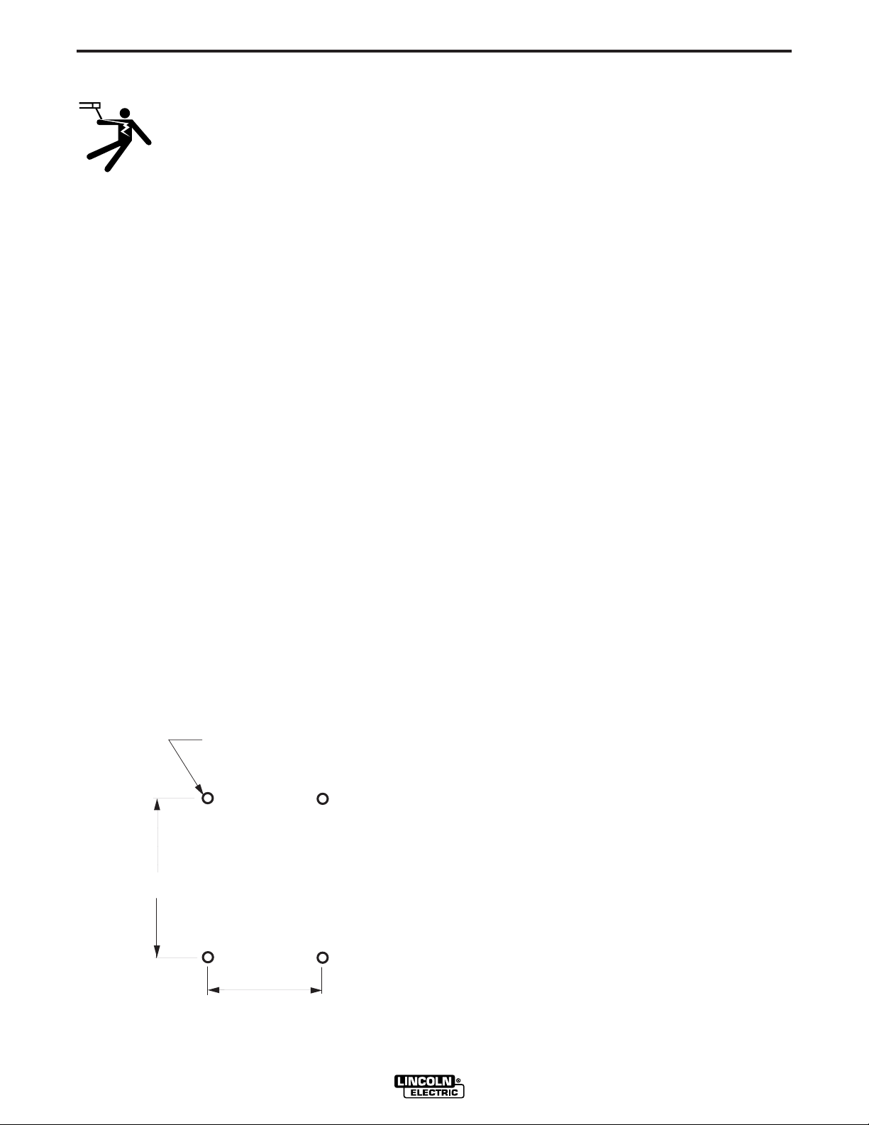
Mount the wire drive unit by means of the 4 holes in
the bottom of the wire drive case. (See Figure A.1)
The gearbox assembly is electrically “hot” when the
gun trigger is pressed. Therefore, make certain the
gearbox does not come in contact with the structure
on which the unit is mounted.
The wire feed unit should be mounted so that the
drive rolls are in a vertical plane, so that dirt will not
collect in the drive roll area. Position the mechanism
so it will point down at about a 45° angle so the wire
feed gun cable will not be bent sharply as it comes
from the unit.
.281(7.14mm) Dia
(4 Holes)
9.00(228.6mm)
The Control Box is designed for use in a variety of
configurations. A boom model feeder is shipped from
the factory separated from the Wire Drive, with the
necessary receptacles installed. In the case of a
bench model feeder, the Control Box can be removed
from the Wire Drive and mounted in a location convenient to the user. Doing so requires separating the
Control Box from the Wire Drive, mounting the Control
Box in the desired location, determining which receptacle configuration is best for the application and
installing the receptacle or receptacles for connecting
control cables in the chosen configuration.
SEPARATING THE CONTROL BOX FROM
THE WIRE DRIVE (BENCH MODEL ONLY)
1. Remove the bottom and center option panels from
the front of the Control Box.
2. Disconnect the Control Box to Wire Drive connection by disconnecting the 6-pin plug located in the
hole which passes through the lower back of the
Control Box to the Wire Drive.
3. Loosen the four screws inside the Control Box
located along the sides of the back of the Control
Box, two near the bottom and two near the middle.
4.75(120.7mm)
BOTTOM FRONT
FIGURE A.1
4. Push the Control Box upwards and pull away from
the Wire Drive.
POWER FEED 10
Page 11
A-3
4
.218(5.54mm) Dia
INSTALLATION
A-3
5. Remove plug button taped to inside of Control Box
and insert it into hole on front panel of the Wire
Drive.
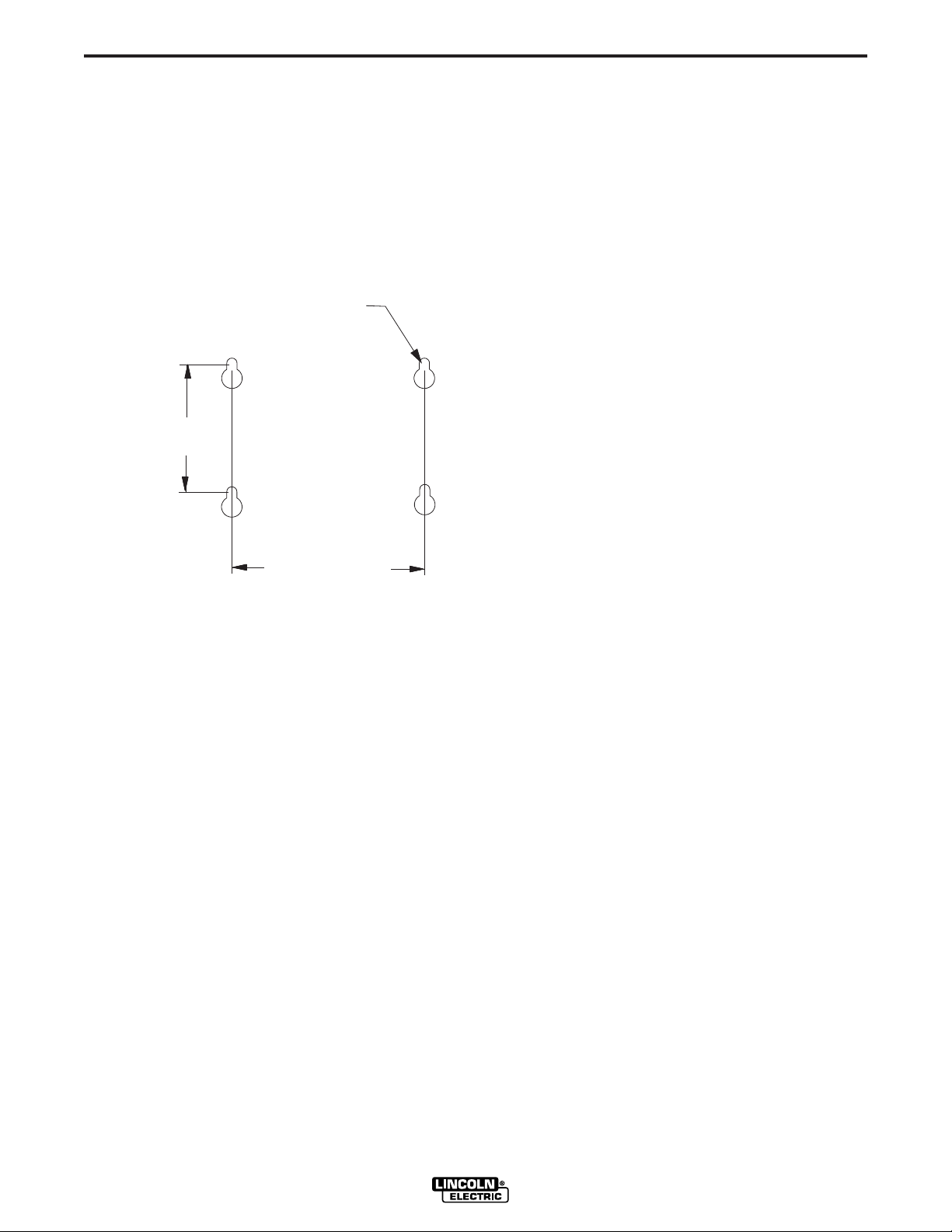
MOUNTING THE CONTROL BOX (BOOM
OR SEPARATED BENCH MODELS)
The back plate of the Control Box has four keyhole
slots for mounting. See Figure A.2 for the size and
location of these slots. #10 screws are recommended
for mounting.
(4 Slots)
.25(108mm)
TOP
6.88(175mm)
FIGURE A.2
installed in the Control Box. An Input/Output
Receptacle Kit, K1548-1, is available for this purpose.
Instructions for installing the receptacles in a Control
Box are included with the kit.
Alternately, a bench feeder can be converted to a
non-typical boom system by installing an output
receptacle in a Wire Drive (use K1549-1) and an input
receptacle in a Control Box (use K1550-1). This system would meet the rule stated above: This means
that the first component in the system (the Power
Wave 455) has an output receptacle. The last component in the system (the Control Box) has an input
receptacle. The component in between (the Wire
Drive) has both an input and output receptacle.
A Control Box can be mounted to the front of a Power
Wave 455. When mounting a Control Box removed
from a bench feeder, no receptacles are required; all
connections are internal. When mounting a Control
Box configured as part of a boom system (both input
and output receptacles are already installed in the
Control Box) the receptacles do not get used. The
wiring harness from either J1 or J2 (the signals are
identical) must be disconnected from the harness on
the back of one of the receptacles (internally). This
open connector is then used during mounting to the
Power Wave 455.
MOUNTING ON POWER SOURCE
DETERMINING RECEPTACLE CONFIGURATION
The components in a Power Wave / Power Feed system are connected in a ʻdaisy chainedʼ fashion. This
means that the first component in the system (always
the Power Wave 455) must have an output receptacle. The last component in the system (typically the
Wire Drive) must have an input receptacle. Every
component in between must have both an input and
output receptacle. (Output receptacles are characterized by having insulated ʻsocketʼ connections, while
input receptacles have uninsulated ʻpinʼ connections.)
In a factory supplied bench system, the Power Wave
455 has an output receptacle, and the Wire Drive has
an input receptacle. The connection between the
Control Box and the Wire Drive is internal; no external
cables or receptacles are required.
In a factory supplied boom system, the Power Wave
455 has an output receptacle, the Control Box has
both input and output receptacles, and the Wire Drive
has an input receptacle.
If a bench feeder is to be converted to a typical boom
feeder, both input and output receptacles must be
Complete instructions for mounting a Control Box to
the front of a Power Wave 455 are included in the
Power Wave 455 Operatorʼs manual.
CONTROL CABLE
CONTROL CABLE CONNECTIONS
• All system control cables are the same.
• All control cables can be connected end to end to
extend their length.
• All system equipment must be connected to a control cable.
The Power Wave / Power Feed Wire Feeders offer
flexibility in the connection of system components.
This system uses the same type of control cable
between all of the system components. Connections
can be “daisy chained” from one system component to
another. Components can be connected in any order,
as long as the proper input and output receptacles are
present. See MOUNTING CONTROL BOX AND
RECEPTACLE CONFIGURATION for details.
NOTE: The maximum cable length between any two
pieces of equipment is 250'.
POWER FEED 10
Page 12

A-4
INSTALLATION
A-4
Typical Bench Feeder Connection:
Control cable is connected from the Power Wave 455
output receptacle to the input receptacle on the back
of the Wire Drive.
Typical Boom Feeder Connection:
One control cable is connected from the Power Wave
455 output receptacle to the Control Box input receptacle. A second control cable is connected from the
Control Box output receptacle to the input receptacle
on the back of the Wire Drive.
Multiple Wire Drive Connection:
For proper multiple wire drive connections and DIP
switch settings contact the Lincoln Electric Company,
Customer Service Department. 1-800-833-WELD.
Non-Typical Boom Feeder Connection:
One control cable is connected from the Power Wave
455 output receptacle to the the input receptacle on
the back of the Wire Drive. A second control cable is
connected from the output receptacle on the back of
the Wire Drive to the Control Box input receptacle.
Control Box Mounted on Power Wave 455:
AVAILABLE CABLE ASSEMBLIES
K1543 Control cable only. Available in lengths of
8'(2.4m), 16'(4.9m), 25'(7.6m), 50'(15.2m) and
100'(30.5m).
K1544 Control cable and a 3/0 (85 mm2 ) electrode
cable with stud terminal. It is rated at 600
amps, 60% duty cycle and is available in
lengths of 8'(2.4m), 16'(4.9m), 25'(7.6m),
50'(15.2m).
K1545 Control cable and a 3/0 (85 mm2) electrode
cable with Twist-Mate™ connector on one end
and a stud terminal on the other. It is rated at
500 amps, 60% duty cycle and is available in
lengths of 8'(2.4m), 16'(4.9m), 25'(7.6m),
50'(15.2m).
ELECTRODE CABLE CONNECTIONS
Most welding applications run with the electrode being
positive (+). For those applications, connect the electrode cable between the wire feeder and the positive
(+) output stud on the power source (located beneath
the spring loaded output cover near the bottom of the
case front).
One control cable is connected from the Power Wave
455 output receptacle to the input receptacle on the
back of the Wire Drive.
See CONTROL AND ELECTRODE CABLE INSTALLATION for cable installation instructions.
CONTROL CABLE SPECIFICATIONS
It is recommended that only genuine Lincoln control
cables be used at all times. Lincoln cables are specifically designed for the communication and power
needs of the Power Wave 455 / Power Feed system.
The use of non-standard cables, especially in lengths
greater than 25 feet(7.6 meters), can lead to communication problems (system shutdowns), poor motor
acceleration (poor arc starting) and low wire driving
force (wire feeding problems).
Lincoln control cables are copper 5 conductor cable in
a SO-type rubber jacket. There is one 20 gauge twisted pair for network communications. This pair has an
impedance of approximately 120 ohms and a propagation delay per foot of less than 2.1 nanoseconds.
There are two 12 gauge conductors that are used to
supply the 40 VDC to the network. The fifth wire is 18
gauge and is used as an electrode sense lead.
For positive porosity application, a work lead must be
run from the negative (-) power source output stud to
the work piece. The work piece connection must be
firm and secure, especially if pulse welding is planned.
Excessive voltage drops at the work piece connection
often result in unsatisfactory pulse welding performance.
When negative electrode polarity is required, such as
in some Innershield™ applications, install as above,
except reverse the output connections at the power
source (electrode cable to the negative (-) stud, and
work cable to the positive (+) stud).
Change electrode polarity Dip Switch in Feed Head,
(see Dip Switch Setup Section).
POWER FEED 10
Page 13
A-5
Connect the one end of the electrode cable, to the
power source output terminal of the desired polarity.
Connect the other end of the electrode cable to the
connection bar at the front of the wire drive feed plate
using the provided bolt and lockwasher. The electrode cable lug must be against the feed plate. Be
sure the cable, connection bar, and gun adapter bushing all make tight metal-to-metal electrical contact.
The Electrode cable should be sized according to the
specifications given in the work cable connections
section.
INSTALLATION
WORK CABLE CONNECTIONS
A-5
WIRE DRIVE GEAR RATIO (HIGH
OR LOW SPEED)
The speed range capability and drive torque of the
Power Feed 10 wire drive can be easily and quickly
changed by changing the external drive gear. The
Power Feed 10 is shipped with both a high speed and
a low speed gear. As shipped from the factory, the low
speed (high torque) gear is installed on the feeder. If
this is the desired gear ratio, no changes need to be
made.
Connect a work lead of sufficient size and length (per
the following table) between the proper output terminal on the power source and the work. Be sure the
connection to the work makes tight metal-to-metal
electrical contact.
To avoid interference problems with other equipment
and to achieve the best possible operation, route all
cables directly to the work or wire feeder. Avoid
excessive lengths, bundle the electrode and ground
cables together where practical, and do not coil
excess cable.
Minimum work and electrode cables sizes are as follows:
Current
60% Duty
Cycle
400 Amps
500 Amps
600 Amps
When using an inverter type power source, use the
largest welding (electrode and ground) cables that are
practical. At least 2/0 copper wire — even if the average output current would not normally require it.
When pulsing, the pulse current can reach very high
levels. Voltage drops can become excessive, leading
to poor welding characteristics, if undersized welding
cables are used.
Minimum Copper Work Cable Size, AWG
Up to 100 ft Length (30m)
2/0 (67 mm2)
3/0 (85 mm2)
3/0 (85 mm2)
SELECTING THE PROPER GEAR RATIO
See the Technical Specifications at the front of this
section for feed speed and wire size capabilities with
high and low speed gear ratios. To determine whether
you should be using the high or low speed ratio use
the following guidelines:
- If you need to operate at wire feed speeds above
800 IPM (20 m/m), you will need to install the high
speed gear (large 30 tooth, 1.6 inch(41mm) diameter
gear).
- If you do not need to run at wire feed speeds in
excess of 800 IPM (20 m/m), you should use the low
speed gear (small, 20 tooth, 1.1 inch(28mm) diameter gear). Using the low speed ratio will provide the
maximum available wire driving force.
If you are feeding only small diameter wires you
Note:
may, at your option, install the high speed ratio.
CHANGING THE WIRE DRIVE RATIO
Changing the ratio requires a gear change and a PC
board switch change. The Power Feed 10 is shipped
with both a high speed and a low speed gear. As
shipped from the factory, the low speed (high torque)
gear is installed on the feeder. For identification purposes, the low speed (high torque) gear has 20 teeth
and is 1.1 inches(28mm) in diameter. The high speed
gear has 30 teeth and is 1.6 inches(41mm) in diameter.
Power down the Power Feed by turning off its
companion Power Wave power source. For maximum safety, disconnect the control cable from the
Power Feed.
------------------------------------------------------------------------
POWER FEED 10
WARNING
Page 14

A-6
INSTALLATION
A-6
RATIO CHANGE PROCEDURE:
1) Pull open the Pressure Door.
2) Remove the Phillips head screw retaining the pinion gear to be changed and remove the gear. If
the gear is not easily accessible or difficult to
remove, remove the feed plate from the gearbox.
To remove feed plate:
a) Loosen the clamping collar screw using a 3/16”
Allen wrench. The clamping collar screw is
accessed from the bottom of the feed plate. It is
the screw which is perpendicular to the feeding
direction.
b) Loosen the retaining screw, which is also
accessed from bottom of feeder, using a 3/16”
Allen wrench. Continue to loosen the screw until
the feed plate can be easily pulled off of the wire
feeder.
3) Loosen, but do not remove, the screw on the
lower right face of the feed plate with a 3/16”
Allen wrench.
head (2 screws).
b) Locate the 8-position DIP switch near the top
edge of the PC board, centered left to right.
The setting will be made on the right most
switch, S8.
c) Using a pencil or other small object, slide the
switch down, to the “0” position, when the low
speed gear is installed. Conversely, slide the
switch up, to the “1” position, when the high
speed gear is installed. Refer to Figure A.3.
d) Replace the cover and screws. The PC board
will “read” the switch at power up, automatically adjusting all control parameters for the
speed range selected.
4) Remove the screw on the left face of the feed
plate. If changing from high speed (larger gear) to
low speed (smaller gear), line the lower hole on
the left face of the feed plate with the threads on
the clamping collar. Line the upper hole with the
threads to install larger gear for high speed feeder. If feed plate does not rotate to allow holes to
line up, further loosen the screw on right face of
feed plate.
5) Remove the small gear from the output shaft.
Lightly cover the output shaft with engine oil or
equivalent. Install gear onto output shaft and
secure with flat washer, lock washer, and Phillips
head screw which were previously removed.
6) Tighten the screw on lower right face of feed
plate.
7) Re-attach feed plate to wire feeder if removed in
Step 2.
8) Feed plate will be rotated out-of-position due to
the gear change. Adjust the angle of the feed
plate per the instructions above.
9) Set the High/Low switch code on Wire Drive PC
board as follows:
a) Remove the cover from the back of the feed
POWER FEED 10
Page 15

A-7
DIP SWITCH SETUP
INSTALLATION
ON
12 3456 78
S1
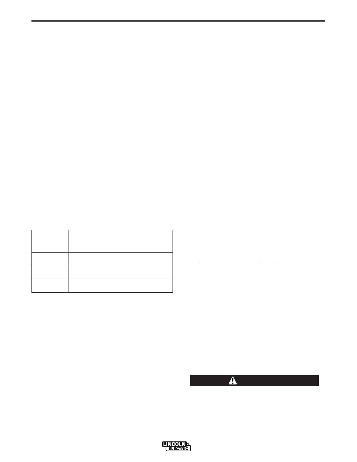
SETTING DIP SWITCHES IN THE
CONTROL BOX
There are two DIP switch banks on the mother board
of the Control Box. They are labeled S1 and S2 and
are located and oriented as shown in Figure A.3.
ON
12 3456 78
FIGURE A.3
S2
S2 DIP Switch Bank on Control Box Motherboard (For software version S24004-2 only)
Switch Off On
1 Network Group ID, MSB (Assigns Control Box to a specific group) (Off is factory setting)
2 Network Group ID, LSB (Assigns Control Box to a specific group ) (Off is factory setting)
3 Spare
4 Spare
5 Spare
A-7
6 Spare
7 Spare
8 Reserved
S1 DIP Switch Bank on Control Box Motherboard (For software version S24004-3 & up)
Switch Off On
1
Standard speed gearbox limits adjustable
2 WFS Display = inches/minute WFS Display = meters/minute
3 Left Display is always preset WFS Left Display is preset WFS when weld current is not flowing
CC modes override this switch regardless of position. Left Display is always preset weld current when weld current is not flowing and actual weld current when weld current is flowing
4 Run-in = Minimum Speed Available Run-in = weld WFS
If any option containing a Run-in setting is connected to the motherboard, it automatically
overrides this switch regardless of position.
High speed gearbox limits adjustable
Left Display is actual weld current when weld current is flowing
5 Memory change with trigger disabled Memory change with trigger enabled
6 Acceleration, MSB (Sets acceleration rate for wire drive) see below
7 Acceleration (Sets acceleration rate for wire drive) see below
8 Acceleration, LSB (Sets acceleration rate for wire drive) see below
Note: the factory shipped settings for all of the S1 and S2 switches is “OFF”.
POWER FEED 10
Page 16

A-8
INSTALLATION
S2 DIP Switch Bank on Control Box Motherboard (For software version S24004-3 & up)
Switch Off On
1 Network Group ID, MSB (Assigns Control Box to a specific group) (Off is factory setting)
2 Network Group ID, LSB (Assigns Control Box to a specific group ) (Off is factory setting)
3 Spare
4 Spare
5 Spare
6 Must be off for normal operation Adjust lower limits
7 Must be off for normal operation Adjust upper limits
8 Must be on for European units only
A-8
S1 DIP Switch Bank on Control Box Motherboard (For software version S24004-2 only)
Switch Off On
1 US 4-Step Trigger Logic Euro 4-Step Trigger Logic
2 WFS Display = inches/minute WFS Display = meters/minute
3 Left Display is always preset WFS Left Display is preset WFS when weld current is not flowing
Left Display is actual weld current when weld current is flowing
CC modes override this switch regardless of position. Left Display is always preset weld current when weld current is not flowing and actual weld current when weld current is flowing
4 Run-in = Minimum Speed Available Run-in = weld WFS
If any option containing a Run-in setting is connected to the motherboard, it automatically
overrides this switch regardless of position.
5 Spare
6 Acceleration, MSB (Sets acceleration rate for wire drive) see below
7 Acceleration (Sets acceleration rate for wire drive) see below
8 Acceleration, LSB (Sets acceleration rate for wire drive) see below
Note: the factory shipped settings for all of the S1 and S2 switches is “OFF”.
MSB - Most Significant Bit or Byte. This is the bit in a binary number or DIP switch bank that is furthest to the left.
LSB - Least Significant Bit or Byte. This is the bit in a binary number or DIP switch bank that is furthest to the right.
POWER FEED 10
Page 17

A-9
INSTALLATION
S1 DIP Switch Bank on Control Box Motherboard (For software version S24456)
Switch Off On
A-9
Standard speed gearbox limits adjustable
1
2 WFS Display = inches/minute WFS Display = meters/minute
3 Left Display is always preset WFS Left Display is preset WFS when weld current is not flowing
CC modes override this switch regardless of position. Left Display is always preset weld current when weld current is not flowing and actual weld current when weld current is flowing
4 Run-in = Minimum Speed Available Run-in = weld WFS
If any option containing a Run-in setting is connected to the motherboard, it automatically
overrides this switch regardless of position.
5 Memory change with trigger disabled Memory change with trigger enabled
6 Acceleration, MSB (Sets acceleration rate for wire drive) see below
7 Acceleration (Sets acceleration rate for wire drive) see below
8 Acceleration, LSB (Sets acceleration rate for wire drive) see below
Note: the factory shipped settings for the S1 switches are as follows:
PF-10 (and Dual) Domestic - All switches “OFF” PF-10 (and Dual) European - switches 1 & 3-8 “OFF”, 2 “ON”
PF-11 Domestic - switches 2-8 “OFF”, 1 “ON” PF-11 European - switches 3-8 “OFF”, 1,2 “ON”
High speed gearbox limits adjustable
Left Display is actual weld current when weld current is flowing
S2 DIP Switch Bank on Control Box Motherboard (For software version S24456)
Switch Off On
1 Network Group ID, MSB (Assigns Control Box to a specific group) (Off is factory setting)
2 Network Group ID, LSB (Assigns Control Box to a specific group ) (Off is factory setting)
3 4-Step Domestic Configuration 4-Step European Configuration
4 Power Feed 10 / Dual Power Feed 11
5 Procedure Change with Trigger “OFF” Procedure Change with Trigger “ON”
6 Set lower limits
7 Set upper limits
8 Must be on for all units (Permits selection of extended modes)
Note: the factory shipped settings for the S2 switches are as follows:
PF-10 (and Dual) Domestic - switches 1-7 “OFF”, 8 “ON” PF-10 (and Dual) European - switches 1,2,4-7 “OFF”, 3,8 “ON”
PF-11 Domestic - switches 1-3,5-7 “OFF”, 4,8 “ON” PF-11 European - switches 1,2,5-7 “OFF”, 3,4,8 “ON”
MSB - Most Significant Bit or Byte. This is the bit in a binary number or DIP switch bank that is furthest to the left.
LSB - Least Significant Bit or Byte. This is the bit in a binary number or DIP switch bank that is furthest to the right.
POWER FEED 10
Page 18
A-10
INSTALLATION
A-10
Setting Wire Drive Acceleration Rate Using (All software versions)
DIP Switch S1 on the Control Box Motherboard
DIP SWITCH 6 DIP SWITCH 7 DIP SWITCH 8
Acceleration 1 (slow) Off Off On
Acceleration 2 Off On Off
Acceleration 3 Off On On
Acceleration 4 On Off Off
Acceleration 5 (fast ) (factory setting) Off Off Off
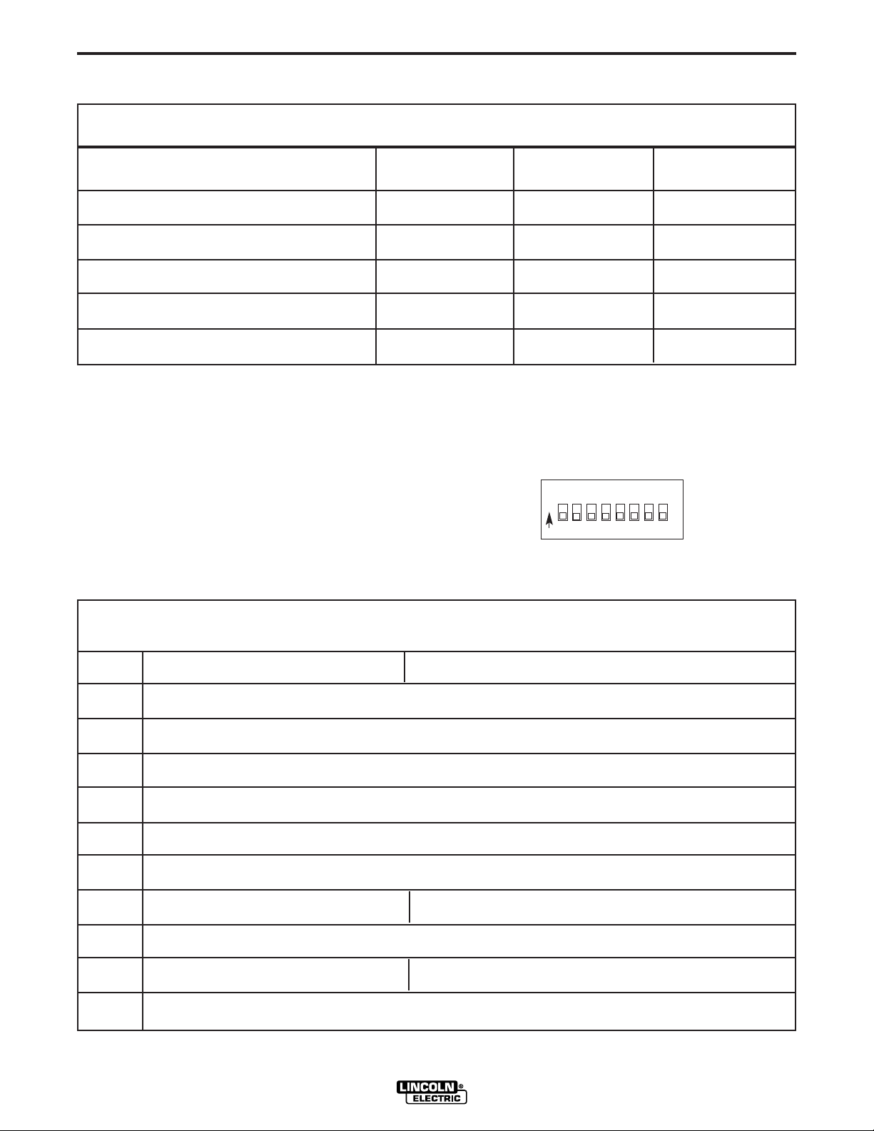
SETTING DIP SWITCHES IN THE WIRE
DRIVE
There is one DIP switch bank on the control board of
the wire drive. Itʼs labeled S1 and is located and oriented as shown in Figure A.4.
ON
12 3456 78
S1
FIGURE A.4
S1 DIP Switch on Wire Drive Control Board (For software version S24029-All & S24467)
Switch Off On
1 Network Group ID, MSB (Assigns Wire Drive to a specific group)
2 Network Group ID, LSB (Assigns Wire Drive to a specific group )
3 Network Feed Head ID, MSB (Assigns feed head number to wire drive)
4 Network Feed Head ID (Assigns feed head number to wire drive)
5 Network Feed Head ID, LSB (Assigns feed head number to wire drive)
6 Spare
7 Electrode Sense Polarity = Positive Electrode Sense Polarity = Negative
Switch position must match polarity of weld cable attached to feed plate.
8 Gear Box Ratio = Low Gear Box Ratio = High
Switch position must match actual gear box ratio of wire drive.
Note: the factory shipped settings for all of the S1 switches is “OFF”.
POWER FEED 10
Page 19
A-11
INSTALLATION
A-11
WIRE FEED DRIVE ROLL KITS
NOTE: The maximum rated solid and cored wire
sizes and selected drive ratios are shown on
the SPECIFICATIONS in the front of this section.
The electrode sizes that can be fed with each roll and
guide tube are stenciled on each part. Check the kit
for proper components. Kit specifications can be
found in the ACCESSORIES section.
PROCEDURE TO INSTALL DRIVE
ROLLS AND WIRE GUIDES
WARNING
ELECTRIC SHOCK can kill.
• Do not touch electrically live parts such
as output terminals or internal wiring.
When feeding without Power Feed 10 “Cold
•
Feed” feature, electrode and drive mechanism
are “hot” to work and ground and could remain
energized several seconds after the gun trigger
is released.
• Turn OFF input power at welding power
source before installation or changing drive
roll and/or guide tubes.
• Welding power source must be connected
to system ground per the National Electrical
Code or any applicable local codes.
• Only qualified personnel should
perform this installation.
Observe all additional Safety Guidelines detailed
throughout this manual.
Drive Roll Kit Installation (KP1505-[ ])
1) Turn OFF Welding Power Source.
2) Pull open Pressure Door to expose rolls and wire
guides.
shaft. (Do Not exceed maximum wire size rating of
the wire drive).
7) Install Outer Wire Guide by sliding over locating
pins and tightening in place.
8) Engage upper drive rolls if they are in the “open”
position and close Pressure Door.
TO SET DRIVE ROLL PRESSURE, see “Drive Roll
Pressure Setting” in OPERATION.
GUN AND CABLE ASSEMBLIES
WITH STANDARD CONNECTION
The Power Feed 10 wire feeder is equipped with a
factory installed K1500-2 gun connection Kit. This kit
is for guns having a Tweco™ #2-#4 connector. The
Power Feed 10 has been designed to make connecting a variety of guns easy and inexpensive with the
K1500 series of gun connection kits. Gun trigger and
dual procedure lead connections connect to the single
5 pin receptacle on the front of the feed head box.
See “Gun Adapters” in ACCESSORIES section.
GUN AND CABLE ASSEMBLIES
WITH FAST-MATE™ CONNECTION
(including the Magnum 450 Water Cooled gun)
A K489-7 adapter will install directly into the wire drive
feedplate, to provide for use of guns with Fast-Mate™
or European style gun connections. This K489-7 will
handle both standard Fast-Mate™and Dual Schedule
Fast-Mate™ guns.
Another way to connect a gun with a Fast-Mate™ or
European style gun connector to the Power Feed 10,
is to use the K489-2 Fast-Mate™ adapter kit.
Installation of this adapter also requires a K1500-1
gun connector. See “Gun Adapters” in ACCESSORIES section.
3) Remove Outer Wire Guide by turning knurled
thumb screws counter-clock-wise to unscrew them
from Feedplate.
4) Remove drive rolls, if any are installed, by pulling
straight off shaft. Remove inner guide.
5) Insert inner Wire Guide, groove side out, over the
two locating pins in the feedplate.
6) Install each drive roll by pushing over shaft until it
butts up against locating shoulder on the drive roll
POWER FEED 10
Page 20

A-12
INSTALLATION
A-12
Magnum 200 / 300 / 400 Guns
The easiest and least expensive way to use Magnum
200/300/400 guns with the Power Feed 10 wire feeder
is to order them with the K466-10 connector kit, or to
buy a completely assembled Magnum gun having the
K466-10 connector (such as the K497-21 dedicated
Magnum 400).
Magnum 550 Guns
The easiest and least expensive way to use the
Magnum 550 guns with Power Feed 10 wire feeders
is to order the gun with the K613-7 connector kit, and
install a K1500-3 gun connection kit to the wire feeder.
Lincoln Innershield and Sub Arc Guns
All of these guns can be connected to the Power Feed
by using the K1500-1 Adapter Kit.
Lincoln Fume Extraction Guns
The K556 (250XA) and K566 (400XA) guns require
that a K489-2 Fast-Mate™ adapter kit be installed.
Installation of this adapter also requires a K1500-1
gun connector kit.
The K206, K289, and K309 require only the installation of a K1500-1 connector in the Power Feed wire
feeder.
Non-Lincoln Guns
Most competitive guns can be connected to the Power
Feed by using one of the K1500 series adapter kits,
See “Gun Adapters” in ACCESSORIES section.
GENERAL GUN CONNECTION
GUIDELINES
GUN CONNECTIONS - GENERAL
4-roll feed plates are equipped with a brass connector
bar at the gun-end of the feed plate to allow a bolted
brass-to-brass electrical connection to be made directly to either standard or Fast-mate gun adapter bushings. Use a 1/4 inch allen key on the factory-installed
socket head cap screw to insure that the connector
bar is securely tightened to the adapter bushing.
The instructions supplied with the gun and K1500
series gun adapter should be followed when installing
and configuring a gun. What follows are some general guidelines that are not intended to cover all guns.
a. Turn off input power at welding power source
before installation or changing of gun.
b. Check that the drive rolls and guide tubes are
proper for the electrode size and type being used.
If not, change them.
c. Lay the cable out straight. Insert the connector
on the welding conductor cable into the brass
conductor block on the front of the wire drive
head. Make sure it is all the way in and tighten
the hand clamp. Keep this connection clean and
bright. Connect the trigger control cable polarized
plug into the mating 5 cavity receptacle on the
front of the wire drive unit.
Note: for Fast-Mate and European connector style
guns, connect gun to gun connector making
sure all pins and gas tube line up with appropriate holes in connector. Tighten gun by turning
large nut on gun clockwise.
d. For GMA Gun Cables with separate gas fittings,
connect the 3/16” I.D. gas hose from the wire
drive unit to the gun cable barbed fitting.
e. For water cooled guns see WATER CONNEC-
TIONS in this section.
POWER FEED 10
Page 21

A-13
INSTALLATION
A-13
GMAW SHIELDING GAS
WARNING
CYLINDER may explode if damaged.
• Keep cylinder upright and chained to
support.
• Keep cylinder away from areas where
it may be damaged.
• Never lift welder with cylinder attached.
• Never allow welding electrode to touch cylinder.
• Keep cylinder away from welding or other live electrical circuits.
BUILDUP OF SHIELDING GAS may
harm health or kill.
• Shut off shielding gas supply when not
in use.
SEE AMERICAN NATIONAL STANDARD Z-49.1,
“SAFETY IN WELDING AND CUTTING” PUBLISHED
BY THE AMERICAN WELDING SOCIETY.
------------------------------------------------------------------------
Customer must provide a cylinder of shielding gas, a
pressure regulator, a flow control valve, and a hose
from the flow valve to the gas inlet fitting of the wire
drive unit.
The upper location must be used for 50-60 lb. ReadiReels, Spools and Coils.
For smaller coils (44lb, 30lb, 10lb, etc.), the spindle
can be placed in either the upper or lower location.
The goal is to make the wire path from the coil to the
wire drive an entry into the incoming guide tube that is
as straight as possible. This will optimize wire feeding
performance.
WATER CONNECTIONS (FOR
WATER COOLED GUNS)
If a water cooled gun is to be installed for use with the
Power Drive 10, a K590-5 Water connection kit can be
installed. Contained in the kit are the water lines and
quick connect water line fittings that install in the wire
feed head. Follow the installation instructions included in the kit. Water cooled guns can be damaged very
quickly if they are used even momentarily without
water flowing. To protect the gun, we recommended
that a water flow sense kit be installed. This will prevent wire feeding if no water flow is present.
Connect a supply hose from the gas cylinder flow
valve outlet to the 5/8-18 female inert gas fitting on the
back panel of the wire drive or, if used, on the inlet of
the Gas Guard regulator. (See Below).
Gas Guard Regulator - The Gas Guard Regulator is
an optional accessory (K659-1) on these models.
Install the 5/8-18 male outlet of the regulator to the
5/8-18 female gas inlet on the back panel of the wire
drive. Secure fitting with flow adjuster key at top.
Attach gas supply to 5/8-18 female inlet of regulator
per instructions above.
WIRE SPINDLE PLACEMENT
The reel stand provides two mounting locations for the
2 inch diameter wire reel spindle to accommodate various reel sizes. Each mounting location consists of a
tube in the center of the reel stand, and locating slots
on the outside of the reel stand. The bolt, used with a
plain washer and lock washer, slides through the tube
from the side of the reel stand. The bolt should be
threaded into the wire spindle such that the tabs on
the brake mechanism align with the locating slots,
then tighten.
WIRE FEED SHUT DOWN CIRCUIT
(OPTIONAL)
This circuit is intended to be used as a means of stopping wire feeding in the event that the water cooler
(for a water cooled gun) is not turned on. Water
cooled guns can be damaged very quickly if they are
used even momentarily without water flowing. A
Lincoln K1536-1 flow sensor kit is available for this
purpose.
The K1536-1 has two control leads coming from the
unit that become electrically common when water is
flowing. The .25 inch tab terminals of leads 570 and
572, inside the feed head case, are disconnected from
each other. Then the flow sensor control wires are
connected to leads 570 and 572. Refer to the instructions that come with flow sensor kit for detailed installation instructions.
POWER FEED 10
Page 22

A-14
INSTALLATION
A-14
OPTIONAL FEATURES INSTALLATION
A number of Optional Features are available for use
with Power Feed 10. Some Installation information is
provided in this section, REFER TO THE INSTRUCTIONS THAT COME WITH EACH KIT FOR
DETAILED INFORMATION REGARDING INSTALLATION.
OPTIONAL PANELS FOR CONTROL BOX
All optional panels for the control box are described in
the ACCESSORIES section of this manual along with
their installation instructions as are all other pieces of
optional equipment.
The PF-10 Control Box is designed to accept three
control panels, two ʻlargeʼ and one “small” panels are
needed to make up a complete control panel for the
Control Box. Panels can be mounted in one of three
positions: Upper, middle and lower.
Each Control Box is shipped with a Control/Display
(CD) panel, a large panel, installed in the upper position, and a CV/Gouge (CV/G) panel (another large
panel) in the lower position. The middle position is
filled with a blank panel.
The CD panel must be installed in every Control Box.
The small panel can be blank, it can be a Dual
Procedure panel, or a Dual Procedure Memory panel.
The remaining large panel can be one of the following:
CV/G, M, MX2, or MSP2. The features of each are
described in the Operation section of this manual.
There are extra mounting holes in the upper and middle positions which allow the upper two panels to be
interchanged. (Instead of the upper, middle and lower
panels being large, small and large, they could be
installed in the order small, large, large.) This may be
done for convenience sake, or to take advantage of
the Large Security Door option.
GENERAL PANEL INSTALLATION
GUIDELINES:
Installation or removal of any panel can be done with
only a Phillips screwdriver after the system power is
turned off. To remove a panel, remove the two screws
holding it in place, remove the push-on chassis
ground wire and remove the harness connection to
the Control Box main PC board. To install any panel,
reverse that process. Turn power back on when complete (option panels are only recognized at power up.
Do not install panels with the power on.) Note that
removal or installation of any panel may also require
the removal of the other panel, in order to have easy
access to the PC board connectors. Detailed installation instructions are shipped with each option panel.
BOOM AND BENCH CONVERSIONS
The modular design of these feeders allows them to
be converted from bench to boom models or vise
versa. Some additional parts are required to make this
conversion.
Materials Required for bench to boom
conversion:
K1548-1 Linc-Net receptacles, installs in control
box.
K1543-“Length” Linc-Net Control Cable, Control
cable between control box and wire drive.
Materials Required for boom to bench
conversion:
L10286-1 Wire Reel Stand.
Note: The CD panel must be installed in either the
middle or the upper position; its harness is not long
enough to allow installation in the lower position.
POWER FEED 10
Page 23

B-1
OPERATION
B-1
SAFETY PRECAUTIONS
WARNING
ELECTRIC SHOCK can kill.
• Do not touch electrically live parts such
as output terminals or internal wiring.
•
When inching with gun trigger, electrode and
drive mechanism are “hot” to work and
ground and could remain energized several
seconds after the gun trigger is released.
• Turn OFF input power at welding power
source before installation or changing
drive roll and/or guide tubes.
• Welding power source must be connected
to system ground per the National
Electrical Code or any applicable local
codes.
• Only qualified personnel should
perform this installation.
Observe all additional Safety Guidelines detailed throughout this manual.
PRODUCT DESCRIPTION
The Power Feed 10 is a high performance, digitally
controlled, modular wire feeder. Properly equipped, it
can support the GMAW, GMAW-P, FCAW, and
SMAW processes. The Power Feed wire feeders are
designed to be a part of a modular, multi process
welding system.
The Power Feed 10 is a 4 driven roll feeder that operates on 40VDC input power. .
RECOMMENDED PROCESSES AND
EQUIPMENT
RECOMMENDED PROCESSES
The Power Feed 10 can be set up in a number of configurations. It is designed to be used for GMAW,
GMAW-P, FCAW, and SMAW for a variety of materials, including mild steel, stainless steel, and cored
wires.
RECOMMENDED EQUIPMENT
The Power Feed 10 must be used with power sources
having digital communication capabilities and 40 VDC
auxiliary power. The presently available power source
is the PowerWave 455.
DUTY CYCLE
The Power Feed 10 wire feeder is capable of welding
at a 100% duty cycle (continuous welding). The power
source will be the limiting factor in determining system
duty cycle capability.
CONTROL BOX OPERATION
The most frequently used Control Box controls and
settings are external; some features are accessed by
internal controls and settings.
CONTROL BOX PANELS - UPPER PANEL
The Power Feed wire feeders are designed to be
used with Power Feed compatible power sources,
operating as a system. Each component in the system
has special circuitry to “talk with” the other system
components, so each component (power source, wire
feeder, electrical accessories) knows what the other is
doing at all times. This shared information lays the
groundwork for a system with superior welding performance.
The Power Feed 10 is available configured in both
boom and bench models. In addition, the Control Box
and wire feed unit can also be purchased separately.
The bench model is designed so that it can easily be
converted to a boom feeder.
POWER FEED 10
CONTROL/DISPLAY PANEL: (REQUIRED)
Each PF-10 Control box must have a Control/Display
(CD) panel. This panel consists of adjustment knobs,
digital displays and a series of indicator lights (LEDs).
There are two knobs; each has a 4 digit LED display
and a pair of LEDs associated with it. Knobs and displays have dual functions; the LEDs indicate which
function at any given time. This panel also has a dual
color Status LED, used to indicate the general health
status of the Control Box and its connection to other
components in the system (power source, wire drive,
etc.).
The left knob/display is labeled WFS / AMPS (wire
feed speed/amps). In non-synergic modes, the WFS
control changes the wire feed speed according to the
desired procedure. In synergic welding modes (synergic CV, pulse GMAW) WFS is the dominant control
parameter, controlling all other variables.
Page 24

B-2
OPERATION
B-2
The user adjusts WFS according to factors such as
weld size, penetration requirements, heat input, etc.
The power source then uses the WFS setting to adjust
its output characteristics (output voltage, output current) according to pre-programmed settings contained
in the power source. In constant current modes (arc
gouging, stick, TIG) this control adjusts the output current, in amps. An LED lights to inform the user which
function (WFS or amps) is active.This display can be
either English or metric units. Further, this display can
be set up to display either WFS or amps when using
wire welding modes. (See SETTING DIP SWITCHES
in the INSTALLATION section.)
The right knob is labeled VOLTS / TRIM. In constant
voltage modes (synergic CV, standard CV) the control
adjusts the welding voltage. In pulse synergic welding
modes (pulse GMAW only) the user can change the
Trim setting to adjust the arc length. It is adjustable
from 0.50 to 1.50. A Trim setting of 1.00 means than
no adjustments will be made to the preset arc lengths,
and is optimum for most conditions. An LED lights to
inform the user which function (volts or trim) is active.
Both displays indicate preset values, according to the
weld mode selected, when not welding. Once welding begins, they switch to displaying actual values. At
that time, the indicator LEDs will flash to signify actual
values are being displayed. The displays hold the
actual values for 5 seconds after a weld is stopped.
Turning a knob during the hold time shuts off the hold,
and returns the meters to their preset values.
The allowable settings are determined by other system components. The WFS range, for instance, is
dependent upon the gear range in the Wire Drive and
on the welding programs in the Power Wave power
source. The voltage and current are similarly limited
by programs in the Power Wave.
CONTROL BOX PANELS - “SMALL” OPTIONAL PANELS
K1542-5 Dual Procedure Panel:
This panel provides for setting and manual selection
of two procedures with a toggle switch. Selection can
be done at the panel, or through a dual procedure
welding gun switch connected to the Wire Drive trigger receptacle. The upper position selects Procedure
A, while the lower selects Procedure B. The middle
position selects the Gun Switch, in which case the
procedure is determined by the dual procedure welding gun switch. Note: When in the Gun Switch
mode, this option does not have provisions for indicating which remotely selected procedure (A or B) is
active.
To set Procedure A, move the switch to the A position.
Make all desired settings on the Control Box. Settings
are automatically saved as changes are made. Do
the same for procedure B. If using a gun switch to
select procedures, set the switch to Gun Switch.
Procedure A is the default if no gun switch is present.
Settings are saved at power down.
K1542-9 Dual Procedure / Memory Panel:
This panel provides two functions: Dual Procedure
and Memory. Dual Procedure provides for setting and
manual selection of two procedures. Selection can be
done at the panel, or through a dual procedure welding gun switch connected to the Wire Drive trigger
receptacle. Memory provides six independent storage
locations for Control Box settings. All selections are
done with push buttons and indicator lights. Dual
Procedure can be used without making use of
Memories; the opposite is also true.
To set Procedure A, hit the Procedure button until the
A LED illuminates. Make all desired settings on the
Control Box. Settings are automatically saved as
changes are made. Do the same for procedure B. If
using a gun switch to select procedures, hit the
Procedure button until the Gun LED illuminates.
When in the Gun mode is selected, either light A or B
will be flashing. The flashing light identifies the
Procedure, A or B, which is selected by a dual procedure gun switch. If no dual procedure switch is
plugged in, the Procedure defaults to A. Settings are
saved at power down.
To load a memory, start by setting all adjustments and
functions on the Power Feed to the desired settings.
To save the settings to Memory 1, simply hit the Save
button (its red light will illuminate) and then hit the 1
button. The settings are now saved in Memory 1. The
contents of Memory 1 will not change, even if the
power is turned off, until the next time the Save key
and the 1 key are hit in sequence. The same procedure can be applied to each of the other 5 memories.
If the Save key is hit accidentally, simply hit the Save
button again, its light will go out, and the Save function will be canceled.
Note: It is not required to load all 6 memories at once,
nor is it necessary to load them in order. Memory can
be loaded at any time, except when welding.
Similarly, the Save key is not active while the gun trigger is pulled, or while welding.
POWER FEED 10
Page 25

B-3
OPERATION
B-3
Memory has an advanced feature called ʻmemory
reminderʼ. When the Save key is hit, the memory
reminder function flashes the LED of the most recently
used memory, so the operator can save procedures in
the most recently used memory if desired. It is not
necessary to save to the most recently used memory;
the memory reminder function, and itʼs flashing LED,
can be ignored.
Memories cannot be changed without using the Save
key. When slight procedure adjustments are necessary, but there is no desire to ʻpermanentlyʼ save the
adjustments to a memory, this can be done with
Procedure A and Procedure B. Set the Panel to A or
B, and recall a memory setting. Make the slight procedure adjustment -- it will be saved in A or B, whichever was selected when the adjustments were made.
The memory location will not have changed.
To recall a memory setting, simply push that memory
button. That memoryʼs contents will be immediately
recalled to the Control box.
If the ʻMemory Change with Trigger Pullʼ DIP switch is
on (see SETTING DIP SWITCHES in the
INSTALLATION section) it is possible to recall a given
memory by quickly pulling and releasing the gun trigger before welding. To switch to memory ʻnʼ, simply
pull and release the gun trigger ʻnʼ times without
attempting to weld. The trigger pulls and releases
must be done quickly, in rapid succession. If too much
time is allowed to pass, the memory location will not
change. Note that whenever the trigger is pulled, a
welding sequence (preflow, run in, etc.) begins, so the
electrode should not be allowed to contact the work
piece.
CONTROL BOX PANELS -- ʻLARGEʼ OPTION PANELS
A description of the set up controls, Preflow, Run In,
Arc Control, Postflow, and Crater, and their maximum
and minimum values, is in CONTROL BOX PANELS SET UP CONTROLS DESCRIPTION in this section.
CV/Gouge Panel:(Std.)
The CV/G Panel has a single toggle switch for selecting between two weld modes: CV welding and arc
gouging. All other set up parameters, Preflow, Arc
Control, Postflow, and Crater, default to zero or off.
Run-in defaults to the minimum value, or to the weld
speed depending on the position of its associated dip
switch. (See SETTING DIP SWITCHES in the
INSTALLATION section.) Burn back defaults to the
on-board trimmer adjustment. When used with the
Dual Procedure or Memory options, only the
WFS/Amps and Volts/Trim settings are saved.
Selecting the Gouge mode immediately energizes the
output terminals on the power source. The output current
is set by the Amps control. The Volts/Trim adjustment
has no effect in this mode.
K1542-6 M Panel:
This panel has a three position toggle switch for
selecting one of three weld modes: CV/MIG, CV/Flux
Cored and CC/Stick/Gouge, and a single knob for
adjustment of Arc Control. All other set up parameters, Preflow, Postflow, and Crater, default to zero or
off. Run-in defaults to the minimum value, or to the
weld speed depending on the position of its associated dip switch. (See SETTING DIP SWITCHES in the
INSTALLATION section.) Burn back defaults to the
on-board trimmer adjustment. When used with the
Dual Procedure or Memory options, only the
WFS/Amps and Volts/Trim settings are saved.
Selecting the CC/Stick/Gouge mode immediately
energizes the output terminals on the power source.
The output current is set by the Amps control. The
Volts/Trim adjustment has no effect in this mode.
K1542-11 MX2 Panel:
This panel provides a selection of four weld modes:
CV/MIG, CV/Flux Cored, CC/Stick/soft and
CC/Stick/Crisp through a toggle switch and indicator
lights (LEDs). It allows for adjustment of all set up
parameters, Preflow, Run In, Arc Control, Burnback,
Postflow, and Crater, through an up/down toggle
switch, indicator lights and a 3 digit display.
Weld modes are selected with the Mode Select
switch, an up/down center-off momentary toggle
switch. Moving the switch bat up or down moves the
Weld Mode LED in the corresponding direction.
Holding the switch in either direction will cause the
indicator to move quickly in the corresponding direction until the switch is released, or the upper or lower
limit is reached.
To adjust Set Up parameters, first select the Set Up
parameter for adjustment, and then adjust the displayed value up or down.
Set Up parameters are selected with the Select
switch, an up/down center-off momentary toggle
switch. Moving the switch bat up or down moves the
Weld Mode LED in the corresponding direction.
Holding the switch in either direction will cause the
indicator to move quickly in the corresponding direction until the switch is released, or the upper or lower
limit is reached.
POWER FEED 10
Page 26

B-4
OPERATION
B-4
The value of the active Set Up parameter, as defined
by the Set Up LED, is displayed on the MX2 panel Set
Up display. The value can be modified with the Set
switch. The Set switch is an up/down center-off
momentary toggle switch. Moving the switch bat up or
down adjusts the displayed value in the corresponding direction. Holding the switch in either direction will
cause the display to move quickly in the corresponding direction until the switch is released, or the upper
or lower parameter limit is reached.
To energize the output studs in either CC/Stick mode,
the right Control/Display panel knob, labeled
Volts/Trim, must be used. The Volts/Trim knob must
be turned clockwise roughly a quarter revolution to
energize the output studs. (The Volts/trim display will
indicate ʻOnʼ when the studs are energized.)
Similarly, turning the knob a quarter turn counterclockwise de-energizes the output studs. If a CC/Stick
weld mode is entered through use of the Dual
Procedure, the studs will be in the same state as
when they were last used. If a CC/Stick weld mode
is entered through a Memory recall, the studs will be
de-energized.
K1542-12 MSP2 Panel:
This panel provides a selection of over 25 weld
modes, including CV, pulse, FCAW and CC, through
a toggle switch and indicator lights (LEDs). It allows
for adjustment of all set up parameters, Preflow, Run
In, Arc Control, Burnback, Postflow, and Crater,
through an up/down toggle switch, indicator lights and
a 3 digit display.
To adjust a set up parameter (Weld Mode being one
of those parameters), first select one of the set up
parameters for adjustment, and then adjust the displayed value up or down.
Set up parameters are selected with the Select switch,
an up/down center-off momentary toggle switch.
Moving the switch bat up or down moves an LED in
the corresponding direction. Holding the switch in
either direction will cause the indicator to move quickly
in the corresponding direction until the switch is
released, or the upper or lower limit is reached.
The value of the active set up parameter is shown on
the MSP2 panel digital display. The value can be modified with the Set switch. The Set switch is an up/down
center-off momentary toggle switch. Moving the switch
bat up or down adjusts the displayed value in the corresponding direction. Holding the switch in either direction will cause the display to move quickly in the corresponding direction until the switch is released, or the
upper or lower parameter limit is reached.
To energize the output studs in either CC/Stick mode,
the right Control/Display panel knob, labeled
Volts/Trim, must be used. The Volts/Trim knob must
be turned clockwise roughly a quarter revolution to
energize the output studs. (The Volts/trim display will
indicate ʻOnʼ when the studs are energized.)
Similarly, turning the knob a quarter turn counterclockwise de-energizes the output studs. If a CC/Stick
weld mode is entered through use of the Dual
Procedure, the studs will be in the same state as
when they were last used. If a CC/Stick weld mode is
entered through a Memory recall, the studs will be deenergized.
CONTROL BOX PANELS -- SET UP
CONTROLS DESCRIPTION
Certain large option panels can modify the set up
parameters Preflow, Run In, Arc Control, Burnback,
Postflow, and Crater. The meaning of those parameters, and their maximum and minimum values, follows.
Preflow - Time delay after the trigger is pulled, but
before weld starts, during which shielding gas flows.
Weld start is defined as the time when both the power
source is energized and the Wire Drive begins feeding
wire. Adjustable from 0.0 (Off) to 2.5 seconds in 0.1s
increments.
Run In - Wire feed speed during arc starting. Wire
Drive will feed wire at the Run In speed for one second, or until weld current flows. Low speed gear
range: Off (Run In speed equals weld wire feed
speed) or adjustable from 50 to 150 IPM (1.25 to 3.80
MPM). High speed gear range: Off (Run In speed
equals weld wire feed speed) or adjustable from 75 to
150 IPM (2.00 to 3.80 MPM). NOTE: Run In settings
over 150 IPM produce strange display values used for
troubleshooting and service. If encountered, reset Run
In to 150 IPM or less.
Arc Control - Unitless characteristic, also known as
Inductance or Wave Control. Allows operator to vary
the arc characteristics from “soft” to “harsh” in all weld
modes. Adjustable from -10.0 to 10.0 in increments of
0.1. Off (0.0) is nominal.
Burnback - Time delay after the trigger is released
during which the power source remains energized but
the Wire Drive stops feeding wire. Adjustable from
0.00 (Off) to 0.25 seconds in 0.01 second increments.
Postflow - Time delay after burnback is complete,
during which shielding gas flows. Adjustable from 0.0
(Off) to 10.0 seconds in 0.1 second increments.
POWER FEED 10
Page 27

B-5
OPERATION
B-5
Crater - Used only when welding with the 4-Step trig-
ger mode. Can be set to Off or On. When On,
Adjustments can be made to WFS and Volts/Trim on
the Control/Display panel. These settings are then
used for ʻcrateringʼ when in the 4-Step trigger mode
(see explanation of 2 Step and 4 Step operation
below). When Off, ʻcrateringʼ is not possible.
CONTROL BOX -- PC BOARD ADJUSTMENTS
The Control Box Mother board provides the capability
to adjust some wire feeding parameters as follows:
Acceleration: The motor acceleration can be varied
in five steps, from slow to fast. See “Setting DIP
Switches in the Control Box” section.
Burnback: For the options which cannot adjust the
Burnback set up parameter (CV/G and M panels) a
PC board adjustment (trimmer R5) is provided. The
range is 0.0 to 0.25 seconds, increasing in the clockwise direction. This is ignored by options which have
the ability to adjust Burnback (MX2 and MSP2 panels).
Run In: For the options which cannot adjust the Run
In set up parameter (CV/G and M panels) a PC board
DIP switch setting is provided. In one position, the run
in speed will be the minimum Wire Drive WFS. At the
other setting, run in will occur at the same speed as
set on the WFS knob. This DIP switch setting is
ignored by options which have the ability to adjust
Run In (MX2 and MSP2 panels). See “Setting DIP
Switches in the Control Box” section.
With system power on, select the weld mode for which
you want to set limits. If a Dual Procedure option is
installed, select the procedure A. Turn the system
power off. Remove the two screws holding the
Control/Display panel to the Control Box, but do not
unplug it. Tilt the panel down to allow access to DIP
switches S1-1, S2-6 and S2-7. (See “Setting DIP
Switches in the Control Box” section.) Do not allow
the panel to hang by the wiring harness.
Determine if the Wire Drive is set up for low or high
speed. If low speed, S1-1 should be off. If high speed,
set S1-1 to on.
To adjust the lower limit, set S2-6 to on. Turn the
power on and adjust the WFS/Amps and Volts/Trim
knobs to the desired lower limits. Note: You will not be
able to adjust the lower limit outside of the minimum
and maximum wire feed speed of the Wire Drive, nor
above the upper limit. Turn the system power off.
Return S2-6 to off.
To adjust the upper limit, set S2-7 to on. Turn the
power on and adjust the WFS/Amps and Volts/Trim
knobs to the desired upper limits. Note: You will not
be able to adjust the upper limit outside of the minimum and maximum wire feed speed of the Wire
Drive, nor below the lower limit. Turn the system
power off. Return S2-7 to off.
If a Dual Procedure panel is installed, repeat the
above procedure with the Procedure B selected.
When done, attach the Control/Display panel to the
Control Box. The machine is now ready for normal
operation with the new limits.
CONTROL BOX -- SETTING OPERATING LIMITS
Upper and lower operating limits can be set for the
WFS/Amps setting and the Volts/Trim setting. Doing
so requires knowledge of how to set the limits, and
access to the PC board in the Control Box.
There are two independent sets of limits, Procedure A
limits and Procedure B limits. If a DP/M door option is
installed, the A and B limits must be set independently. If there is no DP/M door option, the Control Box
defaults to Procedure A, and only Procedure A limits
can be set.
POWER FEED 10
CONTROL BOX -- USING OPERATING LIMITS
Once set, limits apply to all weld modes. Limiting
Procedure A to 200 to 300 inches per minute, for
example, limits the ability of the operator to adjust his
WFS in pulse, CV and FCAW weld modes. Limiting
the Volts to 23.0 to 24.5 would limit the ability of the
operator to adjust his Volts in synergic and non-synergic CV modes. Procedure B could be set up with different limits. Limits are absolute -- they will override
values stored in the memories. Note that limits do not
apply to set up parameters, such a Preflow and Arc
Control.
Page 28

B-6
OPERATION
B-6
OPERATION WITH PREVIOUS
SOFTWARE VERSION
The operation of the previous Control Box software
version (S24004-2) is different than described earlier
in this section. The differences are as follows:
• The Memory/Dual Procedure panel is not a valid
option.
• The MX (K1542-1) and MSP (K1542-8) are are
used in place of the MX2 and MSP2 options.
• Limits cannot be set.
The key difference in the MX/MSP panels, compared
to the MX2/MSP2 panels, is the Spot function. In the
old software, a 0.1 to 2.5 second Spot function was
available on these two panels. No Crater function was
available (Crater replaced Spot in the graphics on
these two panels).
An upgrade kit is available to change the software
from S24004-2 to the latest version of Control Box
software. Once the upgrade is done, the Dual
Procedure/ Memory panel becomes a valid option,
limits can be set, and Spot is replaced by Crater.
2. Opening the trigger after the welding arc is established allows the weld to continue as long as current flows. If the arc goes out, the 4 step cycle is
reset.
3. Closing the trigger again allows the weld to continue.
4. Opening the trigger again ends the arc begins
burnback, postflow, etc..
When using 4 Step Logic With Crater Fill “ON”:
1. Closing the gun trigger initiates the welding
sequence (preflow, run in, etc.).
2. Opening the trigger after the welding arc is established allows the weld to continue as long as current flows. If the arc goes out, the 4 step cycle is
reset.
3. Closing the trigger again changes the wire feed
speed and the Volts/Trim to the Crater values, and
the weld to continues
4. Opening the trigger again ends the arc begins
burnback, postflow, etc..
WIRE DRIVE OPERATION
The most frequently used Wire Drive settings are
external; some features are accessed by internal settings.
WIRE DRIVE SETTINGS -- EXTERNAL
2 STEP / 4 STEP SWITCH:
The Wire Drive has a 2 Step / 4 Step switch located on
the gun side of the Status LED. This switch has no
effect in CC modes of operation, such as stick welding.
When using 2 Step Logic:
1. Closing the gun trigger initiates the welding
sequence (preflow, run in, etc.).
2. Opening the gun trigger ends the arc begins burnback, postflow, etc..
When using 4 Step Logic With Crater Fill “OFF”:
COLD FEED / GAS PURGE SWITCH:
The Wire Drive has a Cold Feed/Gas Purge Switch
located near the gun connector. This is an up/down
center-off momentary toggle switch.
When held in the up position, the Wire Drive will feed
wire, but neither the power source nor the gas solenoid will be energized. When cold feeding, the feed
speed can be adjusted by rotating the WFS encoder
knob on the Control Box. Adjusting the cold feed will
not affect the run in or welding wire feed speed.
When the cold feed switch is released, the cold feed
value is saved.
When this switch is held in the down position, the gas
solenoid valve is energized, but neither the power
source nor the drive motor will be energized.
1. Closing the gun trigger initiates the welding
sequence (preflow, run in, etc.).
POWER FEED 10
Page 29

B-7
OPERATION
B-7
WIRE DRIVE -- PC BOARD ADJUSTMENTS
ELECTRODE POLARITY:
The system needs to be aware of the electrode polarity. A DIP switch setting on the Wire Drive PC board is
used for this purpose. See INSTALLATION Section
“Setting DIP Switches in the Wire Drive”.
GEAR BOX RATIO:
The systems needs to know which gear has been
installed on the Wire Drive, low or high speed. A DIP
switch setting on the Wire Drive PC board is used for
this purpose. See INSTALLATION section “Wire
Drive Ratio” for information on how to set the DIP
Switch.
WIRE REEL LOADING - READI-REELS,
SPOOLS OR COILS
To Mount a 30 Lb. (14 kg) Readi-Reel Package
(Using the Molded Plastic K363-P Readi-Reel
Adapter:)
The Spindle should be located in the LOWER mounting hole.
1) Depress the Release Bar on the Retaining Collar
and remove it from the spindle. See Figure B.1.
2) Place the Adapter on the spindle.
3) Re-install the Retaining Collar. Make sure that the
Release Bar “pops up” and that the collar retainers
fully engage the retaining groove on the spindle.
4) Rotate the spindle and adapter so the retaining
spring is at the 12 o'clock position.
5) Position the Readi-Reel so that it will rotate in a
direction when feeding so as to be de-reeled from
bottom of the coil.
6) Set one of the Readi-Reel inside cage wires on the
slot in the retaining spring tab.
7) Lower the Readi-Reel to depress the retaining
spring and align the other inside cage wires with
the grooves in the molded adapter.
8) Slide cage all the way onto the adapter until the
retaining spring "pops up" fully.
CAUTION
Check to be sure the Retaining Spring has fully
returned to the locking position and has SECURELY
locked the Readi-Reel Cage in place. Retaining
Spring must rest on the cage, not the welding electrode.
___________________________________________
9) To remove Readi-Reel from Adapter, depress
retaining spring tab with thumb while pulling the
Readi-Reel cage from the molded adapter with
both hands. Do not remove adapter from spindle.
POWER FEED 10
Page 30

B-8
OPERATION
FIGURE B.1
To Mount 10 to 44 Lb. (4.5-20 kg) Spools
(12"/300 mm Diameter) or 14Lb.(6 Kg)
Innershield Coils:
The Spindle should be located in the LOWER mounting hole.
(For 8" (200 mm) spools, a K468 spindle adapter must
first be slipped onto spindle.)
B-8
trode on the reel so it unwinds from the bottom as
the reel rotates.
3) Tighten the spinner nut against the reel cover as
much as possible by hand using the reel cover
spokes for leverage. DO NOT hammer on the
spinner nut arms.
4) Cut and remove only the tie wire holding the free
end of the coil. Hook the free end around the rim
of the reel cover and secure it by wrapping it
around. Cut and remove the remaining tie wires.
CAUTION
Always be sure the free end of the coil is securely
held while the tie wires are being cut and until the wire
is feeding through the drive rolls. Failure to do this will
result in “backlashing” of the coil, which may tangle
the wire. A tangled coil will not feed so it must either
be untangled or discarded.
___________________________________________
5) Be sure the coil reel is engaged with the spindle
brake pin and the Release Bar on the Retaining
Collar “pops up” and that the collar retainers fully
engage the retaining groove on the spindle.
SPINNER NUT
(For 13-14 lb. (6 Kg) Innershield coils, a K435 Coil
Adapter must be used).
1) Depress the Release Bar on the Retaining Collar
and remove it from the spindle.
2) Place the spool on the spindle making certain the
spindle brake pin enters one of the holes in the
back side of the spool. Be certain the wire comes
off the reel in a direction so as to de-reel from the
bottom of the coil.
3) Re-install the Retaining Collar. Make sure that the
Release Bar “pops up” and that the collar retainers
fully engage the retaining groove on the spindle.
To Mount a 50-60 Lb. (22.7-27.2 kg) Coil:
(Using K1504-1 Coil Reel) (For 50-60 lb Readi-
Reels a K438 Readi-Reel Adapter must be used).
The Spindle must be located in the UPPER mounting hole.
1) With the K1504-1 Coil Reel mounted on to the 2"
(51 mm) spindle (or with reel laying flat on the
floor) loosen the spinner nut and remove the reel
cover. See Figure B.2.
COVER
PLATE
SLOTS
CARDBOARD
COIL LINER
COIL
TIE WIRE
SPRING
LOADED ARM
REEL
FIGURE B.2
2) Before cutting the tie wires, place the coil of elec-
POWER FEED 10
Page 31

B-9
OPERATION
B-9
FEEDING ELECTRODE AND BRAKE
ADJUSTMENT
1) Turn the Reel or spool until the free end of the
electrode is accessible.
2) While tightly holding the electrode, cut off the bent
end and straighten the first 6" (150 mm). Cut off
the first 1" (25 mm). (If the electrode is not properly straightened, it may not feed or may jam causing
a "birdnest".)
3) Insert the free end through the incoming guide
tube.
4) Press the Cold Inch key or the Cold Feed Mode
gun trigger and push the electrode into the drive
roll.
WARNING
When feeding with the gun trigger, unless “COLD
FEED” trigger mode is selected, the electrode and
drive mechanism are always “HOT” to work and
ground and could remain “HOT” several seconds
after the gun trigger is released.
___________________________________________
5) Feed the electrode through the gun.
6) Adjust the brake tension with the thumbscrew on
the spindle hub, until the reel turns freely but with
little or no overrun when wire feeding is stopped.
Do not overtighten.
1) Press end of gun against a solid object that is
electrically isolated from the welder output and
press the gun trigger for several seconds.
2) If the wire "birdnests", jams, or breaks at the drive
roll, the drive roll pressure is too great. Back the
pressure setting out turn, run new wire through
gun, and repeat above steps.
3) If the only result is drive roll slippage, disengage
the gun, pull the gun cable forward about 6" (150
mm). There should be a slight waviness in the
exposed wire. If there is no waviness, the pressure is too low. Increase the pressure setting
turn, reconnect the gun, tighten locking clamp and
repeat the above steps.
PROCEDURE FOR SETTING ANGLE
OF FEEDPLATE
1) Loosen the clamping collar screw using a 3/16"
Allen wrench. The clamping collar screw is
accessed from the bottom of the feedplate. It is
the screw which is perpendicular to the feeding
direction.
2) Rotate feedplate to the desired angle and tighten
clamping collar screw.
GAS GUARD REGULATOR SETTING
1) With the gas supply shut off, the Gas Guard regu-
lator flow adjusting Key should be set to maximum
(full clockwise) which is rated to be 60 SCFH (28
l/min).
DRIVE ROLL PRESSURE SETTING
The Power Feed 10 pressure is factory pre-set to
about position “2” as shown on the pressure indicator
on the front of the feedplate door. This is an approximate setting.
The optimum drive roll pressure varies with type of
wire, surface condition, lubrication, and hardness.
Too much pressure could cause “birdnesting”, but too
little pressure could cause wire feed slippage with
load and/or acceleration. The optimum drive roll setting can be determined as follows:
POWER FEED 10
2) Adjust gas supply flow rate for a level higher than
will be required, then adjust Gas Guard flow
adjusting Key counterclockwise to the desired gas
flow rate.
Page 32

B-10
OPERATION
B-10
MAKING A WELD
1) Use only a network compatible power source.
2) Properly connect the electrode and work leads for
the correct electrode polarity.
3) Set all desired parameters such as trigger logic,
Run-in Speed, Acceleration, Electrode polarity, etc.
per “DIP SWITCH SETUP” in the INSTALLATION
section.
4)
Set 2-step, 4-step switch on wire drive to desired
mode of operation. (Refer to “2-step/4-step switch
operation” in this section.)
5) Select Weld Mode. (Refer to Control Box
Operation in this section).
6) Use Control Select switches, increment/decrement
switches, and encoder knobs to set desired parameters for weld depending on what options are
installed. (Refer to Control Box Operation in this
section).
7) Feed the electrode through the gun and cable and
then cut the electrode within approximately .38"
(9.5 mm) of the end of the contact tip for solid wire
and within approximately .75" (19mm) of the extension guide for cored wire.
out and Postflow time, if used, is over.
13) If required, starting can be optimized by adjusting
the acceleration and/or run-in speed. (Refer to
Control Box Operation in this section).
WIRE REEL CHANGING
At the end of a coil, remove the last of the old electrode coil from the conductor cable by either pulling it
out at the nozzle end of the gun or by using the following procedure:
1) Cut the end of the electrode off at the gun end. Do
not break it off by hand because this puts a slight
bend in the wire making it difficult to pull it back
through the nozzle.
2) Disconnect the gun cable from the gun connector
on the Power Feed 10 wire drive unit and lay the
gun and cable out straight.
3) Using pliers to grip the wire, pull it out of the cable
from the connector end.
4) After the electrode has been removed, reconnect
the gun cable to the drive. Load a new reel of electrode per the instructions in “Wire Reel Loading” in
this section.
8) Connect work cable to metal to be welded. Work
cable must make good electrical contact to the
work. The work must also be grounded as stated
in "Arc Welding Safety Precautions".
WARNING
When using an Open Arc process,
it is necessary to use correct eye,
head, and body protection.
____________________________________
9) If used, be sure shielding gas valve is turned on.
10) Position electrode over joint. End of electrode
may be lightly touching the work.
11) Lower welding helmet, close gun trigger, and start
welding. Hold the gun so the contact tip to work
distance gives the correct electrical stickout as
required for the procedure being used.
12) To stop welding, release the gun trigger and then
pull the gun away from the work after the arc goes
WIRE FEED OVERLOAD PROTECTION
The wire drive has solid-state overload protection of
the wire drive motor. If the wire drive motor becomes
overloaded for an extended period of time the wire
drive will issue a shutdown command to the Control
Box and force itʼs status light to blink between green
and red. The Control Box turns off the power source,
wire feed and gas solenoid. The status light on the
wire drive will continue to blink between green and red
for about 30 seconds before the wire drive will automatically reset. At that time, the wire drive will issue a
shutdown over command to the Control Box that will
return the system to normal operation. The wire drive
will force itʼs status light to solid green.
Overloads can result from improper tip size, liner,
drive rolls, or guide tubes, obstructions or bends in the
gun cable, feeding wire that is larger than the rated
capacity of the feeder or any other factors that would
impede normal wire feeding. (See “Avoiding Wire
Feeding Problems” in the MAINTENANCE section).
POWER FEED 10
Page 33

B-11
OPERATION
B-11
COMPONENT STATUS LIGHTS
Each network component has a single status light.
The light is a bicolor, Green/Red, LED. The purpose
of the status light is to allow the operator to quickly
identify that the system is working properly or, if not,
NOTE: The green light ON and steady indicates a normal functioning system.
which component is causing the problem. By using
the status lights the operator can quickly pinpoint the
system problem to a particular component. See the
following table for a complete listing and description of
all status light conditions.
STATUS LIGHT STATES
LED State
Off
Green LED blinking at a “normal”
rate
Power Source LED
Power Source is not turned ON or is not
tioning correctly.
It should only blink for a few seconds while
the system is mapping (identifying components). If blinking continues every group may
have a mapping error. (DIP switches may be
set incorrectly).
func-
LED on any other nodes (components);
Wire Feeder, Control Box Etc.
The system component is not receiving input
power or
It should only blink for a few seconds until
the system component (node) has been recognized. If the blinking continues at least
one node in the group has a mapping error
(DIP switches may be set incorrectly). The
node or nodes with mapping errors will be
blinking red.
• There may be too many components in the
group. All components in the group will be
blinking green.
• The power source bus may not be available. The bus may be being used to program another component.
• The LEDʼs of the power source and the
component being programmed will be solid
green.
is faulty.
Red LED blinking
at a “normal” rate
Red/Green LED
blinking at a “normal” rate
Indicates a recoverable communication fault.
The power source should automatically
recover: If it cannot recover the LED will be
solid red.
Indicates a recoverable hardware fault such
as over temperature, overload shutdown etc.
POWER FEED 10
Indicates a recoverable communication fault
most likely caused by one of the following.
• More than one control box (UI) in the
group. All control boxes in the group will be
blinking red.
• No control box (UI) in the group. All nodes
in the group will be blinking red.
• More than one node, of the same equipment type, has the same group and feed
head (FH) numbers. All these nodes will be
blinking red.
• The feed head DIP switches may be set to
zero. The nodes with DIP switches set to
zero will be blinking red.
• The node bus may be off.
Indicates a recoverable hardware fault such
as over temperature, overload shutdown etc.
Could also be an open shutdown circuit at
the feed head (leads 570, 572 with tab terminals) typically used for water flow shutdown
switches.
Page 34

B-12
OPERATION
STATUS LIGHT STATES (CONʼT)
B-12
LED State
Red LED blinking
at a fast rate
Red LED ON and
steady
Green LED ON
and steady
Power Source LED
Power source needs to be reprogrammed.
Contact your Local Authorized Lincoln Field
Service Facility.
Power source has a non-recoverable hardware fault. Contact your Local Authorized
Lincoln Field Service Facility.
System normal and functional.
Normal Blinking LED - Each illumination should exist for 0.5 seconds.
Fast Blinking LED - Each illumination should exist for 0.1 seconds.
LED on any other nodes (components);
Wire Feeder, Control Box Etc.
System component (node) needs to be
reprogrammed. Contact your Local
Authorized Lincoln Field Service Facility.
System component (node) has a non-recoverable hardware fault. Contact your Local
Authorized Lincoln Field Service Facility.
System normal and functional.
POWER FEED 10
Page 35

C-1
ACCESSORIES
TABLE C.1 – DRIVE ROLL AND GUIDE TUBE KITS
C-1
Wire Size
Solid Steel Electrode
0.023” - 0.025” (0.6 mm) KP1505 - 030S
0.030” (0.8 mm) KP1505 - 030S
0.035” (0.9 mm) KP1505 - 035S
0.040” (1.0 mm) KP1505 - 040S
0.040” (1.0 mm) KP1505 - 045S
0.045” (1.2 mm) KP1505 - 045S
0.052” (1.4 mm) KP1505 - 052S
1/16” (1.6 mm) KP1505 - 1/16S
5/64” (2.0 mm) KP1505-5/64
3/32” (2.4 mm) KP1505-3/32
Cored Electrode
0.030 (0.8 mm) KP1505 - 035C
0.035” (0.9 mm) KP1505 - 035C
4-Roll
DH Drive
(4-Driven)
0.040” (1.0 mm) KP1505 - 045C
0.045” (1.2 mm) KP1505 - 045C
0.052” (1.4 mm) KP1505 - 052C
1/16” (1.6 mm) KP1505 - 1/16C
0.068” (1.7 mm) KP1505 - 068
5/64” (2.0 mm) KP1505 - 5/64
3/32” (2.4 mm) KP1505 - 3/32
7/64”
Lincore Hard Facing
7/64” (2.8mm) KP1505 - 7/64
.120” (3.0mm) KP1505 - 120
Aluminum Electrode
0.035” (0.9 mm) KP1507 - 035A
0.040” (1.0 mm) KP1507 - 040A
3/64” (1.2 mm) KP1507 - 3/64A
1/16” (1.6 mm) KP1507 - 1/16A
3/32” (2.2 mm) KP1507 - 3/32A
(2.8mm) KP1505 - 7/64H
POWER FEED 10
Page 36

C-2
ACCESSORIES
C-2
DESCRIPTION AND INSTALLATION OF
OPTIONAL CONTROL BOX PANELS
A number of Optional Features are available for use
with Power Feed 10. Some Installation information is
provided in this section. REFER TO THE INSTRUCTIONS THAT COME WITH EACH KIT FOR
DETAILED INFORMATION REGARDING INSTALLATION.
OPTIONAL PANELS FOR CONTROL BOX
All optional panels for the control box are described in
the ACCESSORIES section of this manual along with
their installation instructions as are all other pieces of
optional equipment.
The PF-10 Control Box is designed to accept three
control panels, two ʻlargeʼ and one “small” panels are
needed to make up a complete control panel for the
Control Box. Panels can be mounted in one of three
positions: upper, middle and lower.
Each Control Box is shipped with a Control/Display
(CD) panel, a large panel, installed in the upper position, and a CV/Gouge (CV/G) panel (another large
panel) in the lower position. The middle position is
filled with a blank panel.
The CD panel must be installed in every Control Box.
The small panel can be blank, it can be a Dual
Procedure panel, or a Dual Procedure Memory panel.
The remaining large panel can be one of the following:
CV/G, M, MX2, or MSP2. The features of each are
described in the Operation section of this manual.
There are extra mounting holes in the upper and middle positions which allow the upper two panels to be
interchanged. (Instead of the upper, middle and lower
panels being large, small and large, they could be
installed in the order small, large, large.) This may be
done for convenience sake, or to take advantage of
the Large Security Door option.
Note: The CD panel must be installed in either the
middle or the upper position; its harness is not long
enough to allow installation in the lower position.
GENERAL PANEL INSTALLATION
GUIDELINES:
Installation or removal of any panel can be done with
only a Phillips screwdriver after the system power is
turned off. To remove a panel, remove the two screws
holding it in place, remove the push-on chassis
ground wire and remove the harness connection to
the Control Box main PC board. To install any panel,
reverse that process. Turn power back on when complete (option panels are only recognized at power up.
Do not install panels with the power on.) Note that
removal or installation of any panel may also require
the removal of the other panel, in order to have easy
access to the PC board connectors. Detailed installation instructions are shipped with each option panel.
K1542-5 DUAL PROCEDURE PANEL
The Dual Procedure Panel provides a fixed large bat
toggle switch or the use of a gun switch for the selection of either of two procedures. The upper position of
the bat switch selects PROCEDURE A, while the
lower selects PROCEDURE B. The middle position
selects the GUN switch, in which case the procedure
is determined by the position of the switch located at
the gun.
NOTE: Due to the nature of fixed position switches,
this option does not allow the indication of a
remotely selected procedure. When in the gun
mode there is no prevision to indicate, at the
Control Box, which procedure has been
remotely selected (at the gun) .
Installation is as follows:
1. Turn off power.
2. Remove the two screws from the front of the standard
or option panel at the location you choose to install your
new option, (middle), of the Control Box cabinet. Save
the screws for re-use. Unplug the white electrical connector. Remove the chassis wire (if equipped) from the
back of the standard or option panel. Discard the old
panel or save for future use.
3. Tilt the new option panel away from the front opening of
the Control Box cabinet and plug the white electrical
connector into the proper connector on the right side of
the main printed circuit board (10 pin) until the connector latches into place. Attach the chassis wire (if
equipped) to the back of the new panel.
4. Slide the new panel through the opening, taking care
not to damage the connections and the printed circuit
board on the back.
5. Align the screw holes. Replace the two screws and
tighten.
POWER FEED 10
Page 37

C-3
ACCESSORIES
C-3
K1542-6 “M” PANEL
The M Panel provides a fixed large bat toggle switch
selection of three Power Source modes. The upper
position selects the generic CV/MIG mode from the
power source, the middle position selects the
CV/FLUX CORED mode, and the lower position
selects the CC/STICK/GOUGE mode. Arc control is
accomplished through the use of the ARC CONTROL
potentiometer. The arc control value is actually a trim
with zero being the nominal and the scale ranging
from (-10) to (+10). Preflow, postflow, and spot time
default to zero or off. Run-in defaults to the minimum
value or weld speed, depending on the position of its
associated dip switch. Burn back defaults to the on
board trimmer adjustment.
NOTE: Due to the nature of fixed position switches,
potentiometers, and default values, this option
does not allow the mode, arc control, timers,
or Burn back values to be included in dual procedure or memory information. They are overridden by the fixed values.
dard or option panel. Discard the old panel or
save for future use.
3. Tilt the new option panel away from the front
opening of the Control Box cabinet and plug the
white electrical connector into the proper connector (12 pin) on the right side of the main printed
circuit board until the connector latches into
place. Attach the chassis wire (if equipped) to the
back of the new panel.
4. Slide the new panel through the opening, taking
care not to damage the connections and the printed circuit board on the back.
5. Align the screw holes, replace the two screws and
tighten.
CC/STICK/GOUGE Mode
Selecting the CC/STICK/GOUGE mode on this panel
automatically energizes the output terminals on the
power source, making the power source immediately
ready to weld. In the CC modes, the output current is
set by the Amps control, and the Volts/Trim adjustment has no effect in this mode. In this mode, the Arc
Control adjusts the arc force. Increasing the Arc
Control setting increases the arc force, making the arc
more harsh but less likely to stick. Decreasing the Arc
Control setting decreases the arc force, making the
arc softer and smoother.
Constant Voltage (CV/Weld, CV/MIG, CV/Flux
Cored) Procedures
When in this mode, the Arc Control adjusts the inductance. (This adjustment is often referred to as ʼpinch”.
Inductance is inversely proportional to pinch.)
Increasing the Arc Control setting decreases the
inductance, which results in the arc getting colder and
pinched tighter. Decreasing the Arc Control setting
increases the inductance, which results in the arc getting wider (reduced pinch).
Installation is as follows:
1. Turn off power.
2. Remove the two screws from the front of the standard or option panel at the location you choose to
install your new option, (bottom), of the Control
Box cabinet. Save the screws for re-use. Unplug
the white electrical connector. Remove the chassis wire (if equipped) from the back of the stan-
POWER FEED 10
Page 38

C-4
ACCESSORIES
C-4
K1542-11 MX2 PANEL (LARGE PANEL)
The MX2 Panel provides a selection of four Power
Source modes. In addition, it provides for the adjustment
of the following parameters: preflow, run in, arc control,
burnback, postflow, and spot time.
Descriptions
Indicator Lights - Extra bright red LEDʼs for viewing at
almost any angle. Always indicate the mode and active
parameter being displayed.
Display - Extra bright, 3 1/2 digit, .56” (14.2 mm) character height, red LED display for viewing at almost any
angle. Displays the value or status of the active parameter.
Available Modes - CV/MIG
CV/ FLUX CORED
CC/STICK CRISP
CC/STICK SOFT
Due to the nature of the system, the following feature is
required for safety reasons: upon entering any constant
current (CC) mode, the right encoder, labeled “Volts,
Trim” on the Display/Control Panel acts as a “soft” contactor switch. The encoder knob must be turned Clock
Wise at least 45° to activate the output (turning Counter
Clock Wise 45° deactivates the output). This prevents
the output from inadvertently becoming “hot” when
scrolling through the weld modes. The exception to this
rule is when the weld mode is entered by a change in
procedure (using a memory panel such as the K1542-9
Memory/Dual Procedure panel). In this case, the state of
the contactor is recalled as it was left when the procedure was exited.
In the CC modes, the output current is set by the Amps
control, and the Volts/Trim adjustment has no effect in
this mode. In this mode, the Arc Control adjusts the arc
force. Increasing the Arc Control setting increases the
arc force, making the arc more harsh but less likely to
stick. Decreasing the Arc Control setting decreases the
arc force, making the arc softer and smoother.
Parameter Ranges:
PREFLOW - 0.0 to 2.5 seconds (0.1 sec. increments).
RUN IN - Low Range: 50 to 150 IPM (1.25 to 3.80 MPM).
- High Range: 75 to 150 IPM (2.00 to 3.80 MPM).
ARC CONTROL - Trim (-10.0) to (+10.0) , (0) is nominal.
BURN BACK - 0.0 to 0.25 sec. (0.01 sec. increments).
POSTFLOW - 0.0 to 2.5 sec. (0.1 sec. increments).
CRATER - ON or OFF (Functions in 4 step trigger mode
only).
in the downward direction. Holding the switch in either
direction will result in the indicator advancing at a high
rate of speed in that direction, until the switch is
released. When the indicator reaches its upper or lower
limit, advancing ceases until the direction of the switch is
changed.
Parameter Selection
The PARAMETER SELECT switch is a momentary large
bat three position toggle switch that defaults to the center
(off) position. Moving the switch bat up advances the
parameter indicator in the upward direction, down
advances it in the downward direction. Holding the switch
in either direction will result in the indicator advancing at
a high rate of speed in that direction, until the switch is
released. When the indicator reaches its upper or lower
limit, advancing ceases until the direction of the switch is
changed.
Parameter Adjustment
The value of the active parameter, as defined by the
parameter indicator, is displayed on the parameter display. The PARAMETER SET switch is a momentary
large bat three position toggle switch that defaults to the
center (off) position. Moving the switch bat up advances
the displayed value in the positive direction, down
advances it in the negative direction. Holding the switch
in either direction will result in the displayed value
advancing at a high rate of speed in that direction, until
the switch is released. When the indicator reaches its
upper or lower limit, advancing ceases until the direction
of the switch is changed.
Crater fill operation is covered in the WIRE DRIVE
OPERATION section.
Installation is as follows:
1. Turn off power.
2. Remove the two screws from the front of the standard or option panel at the location you choose to
install your new option, (bottom), of the Control Box
cabinet. Save the screws for re-use. Unplug the
white electrical connector. Remove the chassis wire
(if equipped) from the back of the standard or option
panel. Discard the old panel or save for future use.
3. Tilt the new option panel away from the front opening of the Control Box cabinet and plug the white
electrical connector into the proper connector (12
pin) on the right side of the main printed circuit
board until the connector latches into place. Attach
the chassis wire (if equipped) to the back of the new
panel.
Mode Selection
The MODE SELECT switch is a momentary large bat
three position toggle switch that defaults to the center
(off) position. Moving the switch bat up advances the
mode indicator in the upward direction, down advances it
POWER FEED 10
4. Slide the new panel through the opening, taking care
not to damage the connections and the printed circuit board on the back.
5. Align the screw holes, replace the two screws and
tighten.
Page 39

C-5
ACCESSORIES
C-5
K1542-12 MSP2 PANEL AND K154210 MS/STT PANEL (LARGE PANEL)
The MSP2 or MS/STT Panel provides a selection of
numerous process specific and generic Power Source
modes. In addition, it provides for the adjustment of
the following parameters: preflow, run in, arc control,
burnback, postflow and spot time. Only one parameter, as defined by the parameter indicator, may be displayed and adjusted at a time.
The installation and operation of the MS/STT panel is
identical to the MSP2 panel. The difference is that the
MS/STT selects STT procedures and is only functional when used with a Power Wave 455 STT Power
Source.
Description:
Indicator Lights - Extra bright red LED for viewing at
almost any angle. Always indicate the active parameter being displayed.
Display - Extra bright, 3 1/2 digit, .56” (14.2 mm) character height, red LED display for viewing at almost
any angle. Displays the value or status of the active
parameter.
Parameter Ranges
WELD MODE - Adjustable per mode schedule.
PREFLOW - 0.0 to 2.5 seconds (0.1 sec. increments).
RUN IN - Low Range: 50 to 150 IPM (1.25 to 3.80 MPM).
- High Range: 75 to 150 IPM (2.00 to 3.80 MPM).
ARC CONTROL - Trim (-10.0) to (+10.0) , (0) is nominal.
BURN BACK - 0.0 to 0.25 sec. (0.01 sec. increments).
POSTFLOW - 0.0 to 2.5 sec. (0.1 sec. increments).
CRATER - ON or OFF (Functions in 4 step trigger
mode only).
Mode Schedule - Table on the front of the option
used by the operator to correlate the displayed mode
number to an actual Power Source mode.
Due to the nature of the system, the following feature
is required for safety reasons: upon entering any constant current (CC) mode, the right encoder, labeled
“Volts”, “Trim”, on the Display/Control Panel acts as a
“soft” contactor switch. The encoder knob must be
turned Clock Wise at least 45° to activate the output
(turning
put). This prevents the output from inadvertently
becoming “hot” when scrolling through the weld
modes. The exception to this rule is when the weld
mode is entered by a change in procedure (using a
memory panel such as the K1542-9 Memory/Dual
Procedure panel). In this case, the state of the contactor is recalled as it was left when the procedure was
exited.
Counter Clock Wise 45° deactivates the out-
POWER FEED 10
In the CC modes, the output current is set by the
Amps control, and the Volts/Trim adjustment has no
effect in this mode. In this mode, the Arc Control
adjusts the arc force. Increasing the Arc Control setting increases the arc force, making the arc more
harsh but less likely to stick. Decreasing the Arc
Control setting decreases the arc force, making the
arc softer and smoother.
Parameter Selection
The PARAMETER SELECT switch is a momentary
large bat three position toggle switch that defaults to
the center (off) position. Moving the switch bat up
advances the parameter indicator in the upward direction, down advances it in the downward direction.
Holding the switch in either direction will result in the
indicator advancing at a high rate of speed in that
direction, until the switch is released. When the indicator reaches its upper or lower limit, advancing ceases
until the direction of the switch is changed.
Parameter Adjustment
The value of the active parameter, as defined by the
parameter indicator, is displayed on the parameter
display. The PARAMETER SET switch is a momentary large bat three position toggle switch that defaults
to the center (off) position. Moving the switch bat up
advances the displayed value in the positive direction,
down advances it in the negative direction. Holding
the switch in either direction will result in the displayed
value advancing at a high rate of speed in that direction, until the switch is released. When the indicator
reaches its upper or lower limit, advancing ceases
until the direction of the switch is changed.
GMAW Pulse Procedures
In these procedures, the actual voltage greatly
depends on the waveform used. The peak currents,
background currents, rise times, fall times, and pulse
times all affect the actual voltage. The actual voltage
for a given wire feed speed is not directly predictable
unless the waveform is known. In this case, it is not
practical to preset an actual voltage for the procedure.
Instead, an arc length adjustment is provided. The
machine “knows” what the best arc length is at the
given wire feed speed but allows the operator to
change it.
The arc length trim (usually referred to simply as
“trim”) can be adjusted between 0.500 and 1.500 on
the Control Boxʼs Volts/Trim display. An Trim of 1.000
means that no adjustments will be made to the preset
arc lengths. A Trim setting less than 1.000 decreases
the preset arc lengths. The arc length trim adjustment
is factored in at all wire feed speed settings.
Increasing the Trim by 10 percent at a given wire feed
speed also increases all the other arc length trim settings of the procedure by 10 percent.
Page 40

C-6
ACCESSORIES
C-6
Lincoln Power Wave power sources utilizes a control
scheme known as adaptive control in all pulse modes.
Because the Power Wave utilizes adaptive control, it
can adjust the pulsing parameters based on changes
in the arc due to changes in the electrical stickout of
the electrode. (Contact Tip to Work Distance(CTWD)
is the distance from the contact to the work piece.)
The Power Wave is optimized for use with a .75” stickout. The adaptive behavior is programmed to support
a stickout range from .5” to 1.25”. In the low and high
end of the wire feed speed ranges of most processes,
the adaptive behavior may be restricted. This is a
physical restriction due to reaching the edge of the
operating range for the process.
The Arc Control adjustment allows the pulse frequency to be varied. Increasing the Arc control causes the
frequency setting to increase, while decreasing the
Arc Control causes the frequency to decrease.
Varying the Arc Control, and hence, the pulse frequency, affects the droplet transfer and allows finetuning for different welding positions.
Crater Fill operation is covered in the WIRE DRIVE
OPERATIONS section.
Installation is as follows:
1. Turn off power.
K1542-9 DUAL PROCEDURE /
MEMORY PANEL (SMALL PANEL)
Note: This panel will function with S24004-3 and high-
er Control Box Software only.
The Dual Procedure / Memory panel provides for the
selection of either of two procedures, or a gun switch
for remote selection of the procedure. In addition,
there are six permanent memory storage locations for
saving commonly used procedures. Procedures A and
B are “soft” type memories that record any changes
made to them. The six memory locations are “hard” or
more permanent type memories. Any changes made
must be consciously saved back to them.
Furthermore, each memory contains only one procedure, therefore any combination of memories may be
recalled to procedure A and B.
Descriptions
Indicator Lights - Extra bright red LEDʼs for viewing at
almost any angle. Always indicate the procedure, also
indicate active memory and save mode if applicable.
Switches - Discreet PC board mounted switches, UL
and CSA approved, with an IEC rating of protection
class IP67.
2. Remove the two screws from the front of the standard or option panel at the location you choose to
install your new option, (bottom), of the Control
Box cabinet. Save the screws for re-use. Unplug
the white electrical connector. Remove the chassis wire (if equipped) from the back of the standard or option panel. Discard the old panel or
save for future use.
3. Tilt the new option panel away from the front
opening of the Control Box cabinet and plug the
white electrical connector into the proper connector (12 pin) on the right side of the main printed
circuit board until the connector latches into
place. Attach the chassis wire (if equipped) to the
back of the new panel.
4. Slide the new panel through the opening, taking
care not to damage the connections and the printed circuit board on the back.
5. Align the screw holes, replace the two screws and
tighten.
Switch Covers - Heavy duty switch covers of silicone
rubber providing a high degree of protection from heat
and dust. Covers are designed to be individually field
replaceable in the unlikely event that one gets damaged.
Dual Procedure Selection
The procedure switch is used to scroll the indicator to
select PROCEDURE A, PROCEDURE B, or the GUN
switch. When the GUN switch is selected, the procedure is determined by the position of the switch located at the gun. Under this condition, indicators will
show that the gun switch has been selected and also
which procedure the gun switch is requesting.
Memory Selection
RECALL - When a memory key is depressed its indicator comes on, and its contents are copied to the
active procedure. As long as no changes are made to
the contents of that procedure, the memory indicator
will be on anytime that procedure is active. This indicates that their contents are the same. Any change to
that procedure will cause the memory indicator to go
off, indicating that they are no longer equal.
POWER FEED 10
Page 41

C-7
ACCESSORIES
C-7
SAVE - The save mode allows “hard” memories to be
changed. Pressing the SAVE key will light the save
indicator, and enter the save mode. In the save mode,
the indicator for the memory that was the source of
the active procedureʼs contents will blink, whether
their contents are still equal or not. This feature allows
the user to choose to save an active procedure back
to its source, or some other location.
To complete the save transaction requires the selection of one of the memory keys. When the memory
key is pressed in the save mode, itʼs contents are
overwritten with the contents of the active procedure.
This means that the contents of the memory location
and the active procedure are now equal, and therefore, by definition, each of their indicators will be lit,
and the save mode will be exited. To exit the save
mode without saving, depress the save key a second
time. This feature allows the operator to determine the
source of the active procedureʼs contents without
actually overwriting it.
Installation is as follows:
1. Turn off power.
K1543, K1544 AND K1545 INPUT
CABLE ASSEMBLIES
Available Cable Assemblies:
K1543 - Control cable only. Consists of a 5-conductor
control cable with a 5-pin control cable plug, without
electrode cable, and is available in lengths of 8'(2.4m),
16'(4.9m), 25'(7.6m), 50'(15.2m) and 100'(30.5m).
K1544 - Consists of a 5-conductor control cable with a
5-pin control cable plug and a 4/0 electrode cable. It is
rated at 600 amps, 60% duty cycle and is available in
lengths of 8'(2.4m), 16'(4.9m), 25'(7.6m), 50'(15.2m).
K1545 - Control cable and a 4/0 (85 mm2) electrode
cable with Twist-Mate™ connector on one end and a
stud terminal on the other. It is rated at 500 amps,
60% duty cycle and is available in lengths of 8'(2.4m),
16'(4.9m), 25'(7.6m), 50'(15.2m).
With input power disconnected from the power
source, install the Control Cable Assemblies per the
instruction in INSTALLATION - “Cable Connections”.
2. Remove the two screws from the front of the standard or option panel at the location you choose to
install your new option, (middle), of the Control
Box cabinet. Save the screws for re-use. Unplug
the white electrical connector. Remove the chassis wire (if equipped) from the back of the standard or option panel. Discard the old panel or
save for future use.
3. Tilt the new option panel away from the front
opening of the Control Box cabinet and plug the
white electrical connector into the proper connector on the right side of the main printed circuit
board (10 pin) until the connector latches into
place. Attach the chassis wire (if equipped) to the
back of the new panel.
4. Slide the new panel through the opening, taking
care not to damage the connections and the printed circuit board on the back.
5. Align the screw holes. Replace the two screws
and tighten.
POWER FEED 10
Page 42

C-8
ACCESSORIES
C-8
K1548-1 LINC NET RECEPTACLE
KIT (INPUT AND OUTPUT)
LINC NET RECEPTACLE (OUTPUT)
Optional Output Connector Installation into the Control
Box Cabinet and/or into the Feeder Head Enclosure.
Control Box Cabinet Procedure
1. Turn off power.
2. Remove the screws from the front of the lower
and middle option panels of the User
Interface cabinet.
3. Tilt the option panels away from the front opening
of the Control Box cabinet. If the option panel has
an electrical connector, disconnect it from the
main printed circuit board (note connection point
for re-connection later). Remove the option panel
and set aside.
4. Remove the plastic plug (black) from the left hole
in the bottom of the Control Box cabinet and store
it in the bottom of the Control Box cabinet for
future use, should the Optional Output Connector
be removed.
Feeder Head Enclosure Procedure
1. Turn power off.
2. Remove the Feeder Head rear access door. The
Feeder Head cover can be removed to aid installation, but is not required.
3. Remove the plastic plug (black) from the hole at
the right rear of the Feeder Head and store it in
the left side of the Feeder Head rear compartment for future use, should the Optional Output
Connector be removed.
4. Disconnect a printed circuit board connector
located at the bottom right corner of the printed
circuit board and position it to the left so as to provide clear access to the lower right corner of the
Feeder Head enclosure.
5. Place the Optional Output Connector (Amphenol)
through the hole opened by the two previous
steps (place from the inside, out). Rotate the
Optional Output Connector so itʼs aligning key is
positioned to the top of the Feeder Head enclosure. Fasten the Optional Output Connector to
the back wall of the Control Box cabinet with the
four screws provided.
5. Place the Optional Output Connector (Amphenol)
through the hole opened by the previous step
(place from the inside, out). Rotate the Optional
Output Connector so itʼs aligning key is positioned
to the front of the Control Box cabinet. Fasten the
Optional Output Connector to the bottom wall of
the Control Box cabinet with the four screws provided.
6. Secure the choke (large circular component of the
Optional Output Connector) by inserting itʼs leads
into the white nylon clip located near the Optional
Output Connector on the back wall of the Control
Box cabinet. Insert the choke leads only.
7. The Optional Output Connector has two internal
connectors, a four pin, and a single lead connector. Connect the four pin connector to the unused
four pin connector on the main printed circuit
board. Connect the single lead connector to a
similar connector found on a lead nearby that
branches out of the Control Box wiring harness.
Re-install the lower and middle option panels by
8.
reversing the removal process. While re-installing the
option panels, ensure clearance between Optional
Output Connector components, Control Box wiring
harness, and option panel harness (if any).
6. Secure the choke (large circular component of the
Optional Output Connector) by inserting itʼs leads
into the white nylon clip located near the Optional
Output Connector on the floor of the Feeder
Head. Insert the long choke leads rather than the
short leads that run between the choke and the
Output Connector. Insert the choke leads only.
7. The Optional Output Connector has two internal
connectors, a four pin, and a single lead connector. Connect the four pin connector to the unused
four pin connector on the printed circuit board.
Connect the single lead connector to a similar
connector found on a lead nearby that branches
out of the Feeder Head wiring harness.
8. Reconnect the printed circuit board connector that
was disconnected earlier.
9. Replace the rear access door and Feeder Head
cover if removed.
POWER FEED 10
Page 43

C-9
ACCESSORIES
C-9
LINC NET RECEPTACLE (INPUT)
Power Feed Wire Feeder Optional Input Connector
Installation into the Control Box Cabinet and
Conversion to Fixture Wire Feeder
1. Turn off power.
2. Remove the screws from the front of the lower
and middle option panels of the Control Box cabinet.
3. Tilt the option panels away from the front opening
of the Control Box cabinet. If the option panel has
an electrical connector, disconnect it from the
main printed circuit board (note connection point
for re-connection later). Remove the option panel
and set aside.
4. Disconnect the connector located at the back wall
of the Control Box cabinet.
5. Loosen (do not remove) the four screws located
on the back wall of the Control Box cabinet.
6. Lift Control Box cabinet off of the four screws
loosened above and set on a work surface. Retighten the four screws to secure for future use.
12. Re-install the lower and middle option panels by
reversing the removal process. While re-installing
the option panels, ensure clearance between
Optional Input Connector components, Control
Box wiring harness, and option panel wiring harness (if any).
K162H - WIRE SPINDLE ADAPTER
Spindle for boom mounting Readi-Reels and 2” (51
mm) I.D. spools with up to 60 lb. (27.2 kg) capacity.
User mounted to appropriately prepared boom framework. Includes an easily adjustable friction brake for
control of overrun (a 2” spindle is standard on Power
Feed 10 Bench model).
When a 2” (51 mm) spindle is used with Readi-Reels,
or coils not on 12” (305 mm) O.D. spools, an adapter
is required:
K1504-1 - COIL ADAPTER
Permits 50 lb to 60 lb (22.7-27.2 Kg.) coils to be
mounted on 2” (51 mm) O.D. spindles.
K435 - COIL ADAPTER
7.
Remove the plastic plug (black) from the right hole
in the bottom wall of the Control Box cabinet and
insert it into the hole in the front of the Feeder Head.
8. Place the Optional Input Connector (Amphenol)
through the hole opened by the previous step
(place from the inside, out). Rotate the Optional
Input Connector so itʼs aligning key is positioned
to the front of the Control Box cabinet. Fasten the
Optional Input Connector to the bottom wall of the
Control Box cabinet with the four screws provided
and connect the optionʼs opposite end to the connector referred to in step 4.
9. Secure the choke (large circular component of the
Optional Input Connector) by inserting itʼs leads
into the white nylon clip located near the Optional
Input Connector on the back wall of the Control
Box cabinet. Insert the choke leads only.
10. Install an Optional Output Connector (Lincoln
stock # K1549-1) into the Control Box cabinet, if
not already present.
11.
Mount the Control Box cabinet to the work station fixture at this time, if desired. The four holes in the back
wall of the Control Box cabinet can be used for this
purpose.
Permits 14 lb. (6 kg) Innershield coils to be mounted
on 2” (51 mm) O.D. spindles.
K363P - READI-REEL ADAPTER
Adapts Lincoln Readi-Reel coils of electrode 30 lb. (14
kg) and 22 lb. (10 kg) to a 2” (51 mm) spindle.
Durable molded plastic one piece construction.
Designed for easy loading; adapter remains on spindle for quick changeover.
K438 - READI-REEL ADAPTER
Adapts Lincoln Readi-Reel coils of electrode 50-60 lb.
(22.7-27.2 kg) to a 2” (51 mm) spindle
POWER FEED 10
Page 44

C-10
ACCESSORIES
C-10
GUNS AND GUN ADAPTERS
The Power Feed 10 wire feeder is equipped with a
factory installed K1500-2 gun connection Kit. This kit
is for guns having a Tweco™ #2-#4 connector. The
Power Feed 10 has been designed to make connecting a variety of guns easy and inexpensive with the
K1500 series of gun connection kits. Gun trigger and
dual procedure lead connections connect to the single
5 pin receptacle on the front of the wire drive box.
MAGNUM 200/300/400 GUNS
The easiest and least expensive way to use Magnum
200/300/400 guns with the Power Feed 10 wire feeder
is to order them with the K466-10 connector kit, or to
buy a completely assembled Magnum gun having the
K466-10 connector (such as the K471-21, -22, and 23 dedicated Magnum 400 guns and the K497-20 and
-21 dedicated Magnum 200 guns).
MAGNUM 550 GUNS
The easiest and least expensive way to use the
Magnum 550 guns with Power Feed 10 wire feeders
is to order the gun with the K613-2 connector kit, and
install a K1500-3 gun connection kit to the wire feeder.
LINCOLN INNERSHIELD AND SUB ARC
GUNS
All of these guns can be connected to the Power Feed
by using the K1500-1 Adapter Kit.
LINCOLN FUME EXTRACTION GUNS
The K556 (250XA) and K566 (400XA) guns require
that a K489-7 Fast-Mate™ adapter kit be installed.
The K206, K289, and K309 require only the installation of a K1500-1 connector in the Power Feed wire
feeder.
NON-LINCOLN GUNS
Most competitive guns can be connected to the Power
Feed by using one of the K1500 series adapter kits.
GUN RECEIVER BUSHINGS AND
ADAPTERS
K489-7 (DUAL SCHEDULE FAST-MATE
ADAPTER)
This adapter installs directly into the wire drive feedplate, to provide for use of guns with Fast-Mate or
European style gun connections. This K489-7 will
handle both standard Fast-Mate and Dual Schedule
Fast-Mate guns.
K1500-1 (LINCOLN INNERSHIELD GUN
STANDARD CONNECTION)
Use this kit to connect the following guns: Guns having a Lincoln standard Innershield gun connector,
Magnum 200/300/400 with K466-1 connector kit, and
Magnum 550 guns with the K613-1 gun connection
kit.
K1500-2 (TWECO #2-#4 TYPE CONNECTION)
The K1500-2 gun adapter comes factory installed on
the Power Feed 10 wire feeder. Use this adapter for
guns that have a Tweco #2-#4 connector. Such guns
include Magnum 200/300/400 guns with K466-2 connector kit, and completely factory assembled Magnum
guns that are factory equipped with the K466-2 connector (such as the K471-21, -22, and -23 dedicated
Magnum 400 guns and the K497-20 and -21 Magnum
200 guns).
K1500-3 (TWECO #5 CONNECTION)
For Magnum 550 gun with K613-2 Connection Kit,
and any other gun having a Tweco #5 connector .
K1500-4 (MILLER CONNECTION)
For any gun having a newer style Miller connector.
Install gun adapters per the instructions shipped with
it.
POWER FEED 10
Page 45

C-11
ACCESSORIES
C-11
CONDUIT ADAPTERS
K1546-2 ADAPTER
for use with Lincoln Magnum conduit and E-Beam
conduit (wire sizes 1/16 - .120)
For Magnum conduit:
Install the K1546-2 gun adapter at the incoming end of
the feed plate, secure with the set screw located at
the back of the feed plate. If a brass fitting is supplied
with the conduit, remove it from the feeder end of the
conduit by unscrewing it. Insert the conduit into the
K1546-2, secure the conduit by fastening it the the
adapter with the supplied knob screw.
For E-Beam Conduit:
Install the K1546-2 gun adapter at the incoming end of
the feed plate, secure with the set screw located at
the back of the feed plate. Insert the conduit into the
K1546-2, secure the conduit by fastening it the the
adapter with the supplied knob screw.
Innershield and Magnum guns, with 15 ft. (4.5 m) control cable and 3-pin plug. K686-2 Adapter permits the
3-pin plug from the K683-1and 5-pin gun trigger plug
to be connected to the 5-pin trigger/dual procedure
receptacle on the wire feeder.
USING DUAL PROCEDURE WITH
FAST-MATE GUNS
There are a number of different options available for
using dual procedure with Fast- Mate guns. These
configurations are outlined below along with any additional required equipment.
USING DUAL SCHEDULE WITH FASTMATE GUNS ON -10 SERIES FEEDERS
Configuration 1
K489-7 Dual Schedule Fast-Mate adapter
K575-[ ] Magnum 400 DS/FM gun (or competitive
DS/FM gun)
DUAL PROCEDURE SWITCH
OPTIONS
K683-3 DUAL PROCEDURE SWITCH
Kit includes gun switch, and mountings for Lincoln
Innershield and Magnum guns, with 15 ft. (4.5m) control cable and 5-pin plug with two leads to connect to
gun trigger.
Connect the 5-pin plug of the K683-3 Dual procedure
Switch to the Power Feed 10 Wire Feeder
Trigger/Dual Procedure 5-socket receptacle.
The two lead plug cord extending out of the 5-pin plug
of the Dual Procedure switch is to be connected to the
two trigger leads of the welding gun per instructions
shipped with the kit.
K683-1 DUAL PROCEDURE SWITCH
The K683-3 Dual Procedure Switch is the recommended method of obtaining dual procedure for nonFast-Mate guns, but a K683-1 can be used. For using
a K683-1 with a fast mate gun, see USING DUAL
PROCEDURE WITH FAST-MATE GUNS. A K683-1
Dual Procedure Switch can be used on the Power
Feed 10 if a K686-2 adapter is used. The K686-2 kit
includes the gun switch and mountings for Lincoln
Configuration 2
K489-7 Dual Schedule Fast-Mate adapter
K683-1 Dual Procedure Switch (3 pin)
K686-2 "Y" adapter (3pin + 5 pin to 5 pin)
* Non-DS Fast-Mate gun (Magnum 450WC, Magnum 200, Magnum 300,
Magnum 400, and others)
*
POWER FEED 10
Page 46

C-12
ACCESSORIES
K590-5 WATER CONNECTION KIT
(FOR DRIVE ONLY)
C-12
K1574-1 SECURITY DOOR (LARGE)
Install per the instructions shipped with the kit.
K1536-1 WATER FLOW SENSOR
KIT
Install per the instructions shipped with the kit
K659-1 GAS GUARD REGULATOR
Adjustable flow regulator with removable adjuster key
for CO2 and Argon blend gases. Mounts onto feeder
inlet, and reduces gas waste and arc start “blow” by
reducing surge caused by excess pressure in supply
hose.
Install the 5/8-18 male outlet of the regulator to the
5/8-18 female gas inlet on the back panel of the wire
drive. Secure fitting with flow adjuster key at top.
Attach gas supply to 5/8-18 female inlet of regulator
per INSTALLATION section.
K1557-1 SWIVEL MOUNT
The K1557-1 Swivel mount attaches to the power
source. This kit includes a feeder adapter plate that
allows the feeder to rotate on top of the power source.
The feeder can be easily separated from the swivel
mount at any time. This option is compatible with the
K1556-1 Light Duty Caster Kit.
K1556-1 LIGHT DUTY CASTER KIT
K1574-1 Security Door Installation into the Control
Box Cabinet
1. Turn off power.
2. Unlatch and swing open the small door. Remove
the two screws from the horizontal hinge rod.
Save the screws.
3. While holding the door so it doesnʼt fall, Slide the
rod out sideways releasing the door.
4. Position the new door between the panel holes
and re-install the rod so the screw holes can be
accessed.
5. Replace the two screws and tighten.
6. Swing the door into the up position. A lock may
be installed through the side holes for security
purposes.
K1555-1 INSULATED LIFT HOOK
For applications where an insulated lift hook is
required. This kit provides an easily installed, heavy
duty insulated lift eye that mounts to the wire reel
stand mast. See the instructions provided with the kit
for installation.
K1551-2 INCOMING BUSHING
(4 Ball Roller) (Standard on codes
10600 and up)
This option provides 4 casters and all required hardware to mount it to the Power Feed 10. This option is
compatible with the K1557-1 Swivel Mount.
POWER FEED 10
This ball bearing equipped incoming bushing can be
used in place of the standard incoming wire bushing,
when feeding solid steel or cored wire electrodes. It
significantly reduces any abrasion to the electrode
wire where it enters the feed head. This results in
even smoother, more trouble free operation.
Page 47

D-1
MAINTENANCE
MAINTENANCE
Avoiding Wire Feeding Problems
D-1
Safety Precautions
WARNING
ELECTRIC SHOCK can kill.
• Do not touch electrically live parts such
as output terminals or internal wiring.
•
When inching with gun trigger, electrode and
drive mechanism are “hot” to work and
ground and could remain energized several
seconds after the gun trigger is released.
• Turn OFF input power at welding power
source before installation or changing
drive roll and/or guide tubes.
• Welding power source must be connected
to system ground per the National
Electrical Code or any applicable local
codes.
• Only qualified personnel should
perform maintenance work.
Observe all additional Safety Guidelines detailed
throughout this manual.
Routine Maintenance
Wire feeding problems can be avoided by observing
the following gun handling and feeder set up procedures:
a) Do not kink or pull cable around sharp corners.
b) Keep the electrode cable as straight as possible
when welding or loading electrode through cable.
c) Do not allow dolly wheels or trucks to run over
cables.
d) Keep cable clean by following maintenance
instructions.
e) Use only clean, rust-free electrode. The Lincoln
electrodes have proper surface lubrication.
f) Replace contact tip when the arc starts to become
unstable or the contact tip end is fused or
deformed.
g) Do not use excessive wire spindle brake settings.
h) Use proper drive rolls, wire guides and drive roll
pressure settings.
Drive Rolls and Guide Tubes
After feeding every coil of wire, inspect the drive roll
section. Clean it as necessary. The driver rolls and
Inner Wire Guides are stamped with the wire sizes
they will feed. If a wire size other than that stamped
on the roll(s) is to be used, the roll(s) and Inner Wire
Guides must be changed.
All drive rolls have two identical grooves. The rolls
may be flipped over to use the other groove.
See “Procedure to Install Drive Rolls and Wire
Guides” in the INSTALLATION section for roll changing instructions.
Wire Reel Mounting - Readi-Reels and
10 through 30lb (4.5-14kg) Spools
No routine maintenance required.
Periodic Maintenance
Wire Drive Motor and Gearbox
Every year inspect the gearbox and coat the gear
teeth with a moly-disulfide filled grease. Do not use
graphite grease.
Every six months check the motor brushes. Replace
them if they are less than 1/4” long.
Gun and Cable Maintenance
See appropriate Operatorʼs Manual.
Procedure for Removing Feedplate from
Wire Feeder
1) Loosen the clamping collar screw using a 3/16"
Allen wrench. The clamping collar screw is
accessed from the bottom of the feedplate. It is
the screw which is perpendicular to the feeding
direction.
2) Loosen the retaining screw, which is also
accessed from bottom of feeder, using a 3/16"
Allen wrench. Continue to loosen the screw until
the feedplate can be easily pulled off of the wire
feeder.
POWER FEED 10
Page 48

E-1
TROUBLESHOOTING
HOW TO USE TROUBLESHOOTING GUIDE
WARNING
Service and Repair should only be performed by Lincoln Electric Factory Trained Personnel.
Unauthorized repairs performed on this equipment may result in danger to the technician and
machine operator and will invalidate your factory warranty. For your safety and to avoid
Electrical Shock, please observe all safety notes and precautions detailed throughout this
manual.
__________________________________________________________________________
This Troubleshooting Guide is provided to
help you locate and repair possible machine
malfunctions. Simply follow the three-step
procedure listed below.
E-1
Step 1. LOCATE PROBLEM (SYMPTOM).
Look under the column labeled “PROBLEM
(SYMPTOMS)”. This column describes
possible symptoms that the machine may
exhibit. Find the listing that best describes
the symptom that the machine is exhibiting.
Step 2. POSSIBLE CAUSE.
The second column labeled “POSSIBLE
CAUSE” lists the obvious external possibilities that may contribute to the machine
symptom.
WARNING
ELECTRIC SHOCK can kill.
• Do not touch electrically live parts such
as output terminals or internal wiring.
•
When inching with gun trigger, electrode and
drive mechanism are “hot” to work and
ground and could remain energized several
seconds after the gun trigger is released.
• Turn OFF input power at welding power
source before installation or changing
drive roll and/or guide tubes.
• Welding power source must be connected
to system ground per the National
Electrical Code or any applicable local
codes.
• Only qualified personnel should perform
these trouble shooting procedures.
Step 3. RECOMMENDED COURSE OF
ACTION
This column provides a course of action for
the Possible Cause, generally it states to
contact you local Lincoln Authorized Field
Service Facility.
If you do not understand or are unable to
perform the Recommended Course of
Action safely, contact you local Lincoln
Authorized Field Service Facility.
Observe all additional Safety Guidelines detailed
throughout this manual.
CAUTION
If for any reason you do not understand the test procedures or are unable to perform the tests/repairs safely, contact your
Local Lincoln Authorized Field Service Facility for technical troubleshooting assistance before you proceed.
POWER FEED 10
Page 49

E-2
PROBLEMS
(SYMPTOMS)
TROUBLESHOOTING
Observe all Safety Guidelines detailed throughout this manual
POSSIBLE CAUSE
RECOMMENDED
COURSE OF ACTION
E-2
1. Rough wire feeding or wire not
feeding but drive rolls are turning.
a. Gun cable kinked and/or twisted.
b. Wire jammed in gun and cable.
Check for mechanical restrictions
in feeding path.
c. Check for current position of drive
rolls Relative to split wire guide
groove.
d. Drive rolls may not be seated
properly.
e. Gun cable dirty. - Clean if neces-
sary.
f. Worn drive roll.
g. Electrode rusty and/or dirty.
Cable frayed, or poor solder joint
at work or electrode lug.
h. Worn nozzle or cable liner. -
Replace if necessary.
If all recommended possible areas of
misadjustment have been checked
and the problem persists, Contact
your local Lincoln Authorized
Field Service Facility.
I. Partially flashed or melted contact
tip. - Replace if necessary.
j. Incorrect drive roll pressure. -
Readjust if necessary.
k. Improper liner, tip or inner/outer
guides. - Replace if necessary.
CAUTION
If for any reason you do not understand the test procedures or are unable to perform the tests/repairs safely, contact your
Local Lincoln Authorized Field Service Facility for technical troubleshooting assistance before you proceed.
POWER FEED 10
Page 50

E-3
PROBLEMS
(SYMPTOMS)
TROUBLESHOOTING
Observe all Safety Guidelines detailed throughout this manual
POSSIBLE CAUSE
RECOMMENDED
COURSE OF ACTION
E-3
2. Variable or “hunting arc.
3. Poor arc striking with sticking or
“blast-offs”, weld porosity, narrow
and ropy looking bead, or electrode
stubbing into plate while welding.
a. Wrong size, worn and/or melted
contact tip. - Replace if necessary.
b. Worn work cable or poor work
connection. - Replace if necessary.
c. Loose electrode or work cable
connections.
d. Wrong polarity. - Make sure elec-
trode polarity is correct for
process being used.
e. Gas nozzle extended beyond gun
tip or wire stickout too long while
welding.
f. Poor gas shielding on processes
requiring gas. - Check gas flow
and mixture.
a. Improper procedures or tech-
niques. - See “Gas Metal Arc
Welding Guide” (GS-100).
b. Improper gas shielding - Clean
gas nozzle. Make certain that gas
diffuser is not empty or turned off.
Make certain gas flow rate is
proper.
If all recommended possible areas of
misadjustment have been checked
and the problem persists, Contact
your local Lincoln Authorized
Field Service Facility.
Remove gun liner and check rubber seal for any sign of deterioration or damage. Be sure set
screw in connector block is in
place and tightened against the
liner bushing.
CAUTION
If for any reason you do not understand the test procedures or are unable to perform the tests/repairs safely, contact your
Local Lincoln Authorized Field Service Facility for technical troubleshooting assistance before you proceed.
POWER FEED 10
Page 51

E-4
PROBLEMS
(SYMPTOMS)
TROUBLESHOOTING
Observe all Safety Guidelines detailed throughout this manual
POSSIBLE CAUSE
RECOMMENDED
COURSE OF ACTION
E-4
4. Tip seizes in diffuser.
5. Unit shuts off while welding or
attempting to weld, status light is
red/green alternating between
colors every second. Unit tries to
recover after 30 seconds and
may repeat again.
6. Drive roll does not turn although
arc voltage is present, and solenoid
is on. Feed head and Control Box
status LEDs are both solid green.
a. Tip overheating due to prolonged
or excessive high current and/or
duty cycle welding.
Note: A light application of high
temperature antiseize lubricant (such as Lincoln E2067
Graphite Grease) may be
applied to tip of threads.
a. Wire feed shut down circuit
maybe electrically open. (Leads
570 and 572 in wire feed head.
b. The wire drive motor may be
overloaded. Check for mechanical restrictions in the wire feeding
path.
a. Check for loose or broken leads
at the wire drive motor.
b. Defective wire feed motor or feed
head PC board. Note: With WFS
set to max control board should
supply 24 VDC to motor (leads
#550, #551).
If all recommended possible areas of
misadjustment have been checked
and the problem persists, Contact
your local Lincoln Authorized
Field Service Facility.
CAUTION
If for any reason you do not understand the test procedures or are unable to perform the tests/repairs safely, contact your
Local Lincoln Authorized Field Service Facility for technical troubleshooting assistance before you proceed.
POWER FEED 10
Page 52

E-5
PROBLEMS
(SYMPTOMS)
TROUBLESHOOTING
Observe all Safety Guidelines detailed throughout this manual
POSSIBLE CAUSE
RECOMMENDED
COURSE OF ACTION
E-5
7. No wire feed, solenoid, or arc
voltage. Status LEDs are solid
green.
8. No control of wire feed.
All status lights are solid green.
Preset WFS is adjustable on
Control Box
9. Wire feed motor turns and solenoid operates, but no arc voltage
is present. Status light is solid
green on Control Box.
a. Faulty gun trigger switch. The gun
trigger switch or circuit may be
faulty. Check or Replace.
a. Defective motor tach or control
PC board, or harness. Check for
loose or faulty connections on
motor tach. See Wiring Diagram.
a. Power source is unable to
respond due to thermal or other
type of shut down mode.
b. Power source is defective. See
Power Source LED Status Light
Chart.
If all recommended possible areas of
misadjustment have been checked
and the problem persists, Contact
your local Lincoln Authorized
Field Service Facility.
CAUTION
If for any reason you do not understand the test procedures or are unable to perform the tests/repairs safely, contact your
Local Lincoln Authorized Field Service Facility for technical troubleshooting assistance before you proceed.
POWER FEED 10
Page 53

E-6
PROBLEMS
(SYMPTOMS)
TROUBLESHOOTING
Observe all Safety Guidelines detailed throughout this manual
POSSIBLE CAUSE
RECOMMENDED
COURSE OF ACTION
E-6
10. Speed does not change when
weld current flows. Status lights
are solid green.
11. Voltmeter and/or ammeter do
not function properly even
though status lights are solid
green. Welding may vary from
normal procedure.
12. Purge switch on feed head does
not activate solenoid but trigger
closure in MIG or pulse modes
does.
a. Run-in and weld speeds are set to
the same value.
b. Possible problem with current
sensor electronics in power
source. Check power source manual to trouble shoot current sensor
electronics.
a. 67 and/or 21 voltage sense leads
may have intermittent or poor connections. Check.
b. Possible problem with power
source electronics.
a. Defective gas purge switch or
feed head board. Check continuity
with gas purge switch held down
across J1 pins 3 and 5. Release
purge switch and note there
should be no continuity now. If
either of these fail, the problem is
either in the gas purge switch or
harnessing. If no failure, replace
feed head board.
If all recommended possible areas of
misadjustment have been checked
and the problem persists, Contact
your local Lincoln Authorized
Field Service Facility.
13. Cold feed switch does not acti-
vate the motor but trigger does
in MIG or Pulse modes. LEDs
are solid green on both CB and
feed head boards.
a. Defective cold feed switch or feed
head PC board. Check continuity
with cold feed switch held up
across plug pins 3 and 4 of J1.
Release the cold inch switch and
note that there should be no continuity now. If either of these fail,
the problem is either in the purge
switch or harnessing. If continuity
O.K., replace feed head board.
CAUTION
If for any reason you do not understand the test procedures or are unable to perform the tests/repairs safely, contact your
Local Lincoln Authorized Field Service Facility for technical troubleshooting assistance before you proceed.
POWER FEED 10
Page 54

E-7
PROBLEMS
(SYMPTOMS)
TROUBLESHOOTING
Observe all Safety Guidelines detailed throughout this manual
POSSIBLE CAUSE
RECOMMENDED
COURSE OF ACTION
E-7
14. Displays and/or indicator lights
do not change when their corresponding switches and or knobs
are activated to request a
change.
a. The encoders or switches may be
faulty.
b. Check for broken harness wire(s)
or harness disconnected from
intended location.
If all recommended possible areas of
misadjustment have been checked
and the problem persists, Contact
your local Lincoln Authorized
Field Service Facility.
CAUTION
If for any reason you do not understand the test procedures or are unable to perform the tests/repairs safely, contact your
Local Lincoln Authorized Field Service Facility for technical troubleshooting assistance before you proceed.
POWER FEED 10
Page 55

E-8
PROBLEMS
(SYMPTOMS)
TROUBLESHOOTING
Observe all Safety Guidelines detailed throughout this manual
POSSIBLE CAUSE
RECOMMENDED
COURSE OF ACTION
E-8
15. Display(s) are blank.
16. Dual Procedure is not function-
ing when using remote dual procedure switch. Status lights are
solid green on Circuit Boards
and head boards.
a. Power source is OFF.
b. Feeder supply or fuse circuit at
power source is blown or tripped,
or defective harness or cabling.
c. Display or Circuit Boards may be
faulty.
a. Gun has not been selected at the
control box. Set dual procedure
switch on Circuit Board to gun.
Refer to operating instructions.
b. Faulty remote dual procedure
switch. Remove switch. Check
continuity between switch pins
with switch open and closed. If it
fails the continuity test, repair or
replace switch.
c. Faulty Local Dual procedure
switch.
If all recommended possible areas of
misadjustment have been checked
and the problem persists, Contact
your local Lincoln Authorized
Field Service Facility.
CAUTION
If for any reason you do not understand the test procedures or are unable to perform the tests/repairs safely, contact your
Local Lincoln Authorized Field Service Facility for technical troubleshooting assistance before you proceed.
POWER FEED 10
Page 56

E-9
PROBLEMS
(SYMPTOMS)
TROUBLESHOOTING
Observe all Safety Guidelines detailed throughout this manual
POSSIBLE CAUSE
RECOMMENDED
COURSE OF ACTION
E-9
17. Dual Procedure is not function-
ing when using the local dual
procedure switch (on Circuit
Boards). Status lights are solid
green on Circuit Boards and
Head boards.
18. Wire feed speed is consistent
and adjustable, but operates at
the wrong speed.
a. Faulty local dual procedure
switch or Circuit Boards mother
board. Disconnect harness plug
from J5 of Circuit Board mother
board. Check that there is continuity between plug pins 1 and 7
local DPS is in position “A” but
not when in gun or “B”. Now
check that there is continuity
between plug pins 1and 8 when
local DPS is in position “B” but
not when in “Gun” or “A”. If any
of these continuity tests fail,
repair or replace switch or switch
harness to correct the problem,
Otherwise, replace CB mother
board.
a. Dip switch on feed head board
does not match gear ratio used at
gear box. If using a high speed
gear, the feed head PC board dip
switch 8 must be set to 1 or “ON”.
b. Feed head board is not properly
reading DIP switch. Replace feed
head PC board.
If all recommended possible areas of
misadjustment have been checked
and the problem persists, Contact
your local Lincoln Authorized
Field Service Facility.
19. Status LED not solid green
a. see LED Status Light Chart.
CAUTION
If for any reason you do not understand the test procedures or are unable to perform the tests/repairs safely, contact your
Local Lincoln Authorized Field Service Facility for technical troubleshooting assistance before you proceed.
POWER FEED 10
Page 57

E-10
TROUBLESHOOTING
Observe all Safety Guidelines detailed throughout this manual
E-10
Note:
For any Err # listed below write down the error number for reference and try cycling power to see if the
error clears itself. If not, refer to the What to Do column for the given Err.
PROBLEMS
(SYMPTOMS)
Display shows any of the following:
Err 001
Err 003
Err 004
POSSIBLE CAUSE
More than 1 Circuit Board with the
same group number.
Too many objects in group.
More than 1 object of the same
equipment type with the same group
# and feed head #.
RECOMMENDED
COURSE OF ACTION
Make sure the group dip switch setting is unique for each Circuit Board.
A given group can only support up to
7 objects. Remove any objects over
7 from the group either by changing
the group dip switch settings or
physically disconnecting any objects
over 7 in the group.
Adjust the dip switch setting to make
either the group # or feed head #
unique for all objects of the same
equipment type.
Err 005
Err 006
A feed head has its feed head dip
switches set to zero in a group with
more than one object.
Did not receive a recognition command from the power source.
The appropriate feed head # is 1
through 7. Check the dip switch setting chart in INSTALLATION section
and set the switches to make the
Feed head ID non-zero.
Check to see if the status light is not
solid green on the power source
(refer to status light states in OPERATION section if not). Also, check
continuity in the communication lines
from CB to Power Source (refer to
wiring diagram). Refer to Power
source trouble shooting section for
additional information. If all these
avenues fail, replace CB mother PC
board.
CAUTION
If for any reason you do not understand the test procedures or are unable to perform the tests/repairs safely, contact your
Local Lincoln Authorized Field Service Facility for technical troubleshooting assistance before you proceed.
POWER FEED 10
Page 58

E-11
TROUBLESHOOTING
Observe all Safety Guidelines detailed throughout this manual
E-11
Note:
For any Err # listed below write down the error number for reference and try cycling power to see if the
error clears itself. If not, refer to the What to Do column for the given Err.
PROBLEMS
(SYMPTOMS)
Display shows any of the following:
Err 020
Err 100
Err 200
Err 201
POSSIBLE CAUSE
An attempt was made to reprogram
a Circuit Board or feed head but the
program did not verify.
The Power Source issued a shut
down command for some reason.
No Heart beat response from the
Power Source.
No heart beat response from an
object.
RECOMMENDED
COURSE OF ACTION
Check for potential electrical HF
noise generators in the area. Try
removing the noise source and programming again. If the Err 020 still
occurs, either replace the EEPROM
chip(s) in the board being reprogrammed or replace the whole PC
board being reprogrammed.
See what to Do on Err 006.
See what to Do on Err 006.
If this occurs while welding, the status LED should be flashing red on
the object that lost heart beat.
Otherwise, look for any nodes that
are flashing green. This indicates
they have not been recognized and
there is a power source problem
(see power source trouble shooting
section). If the status LED is either
flashing or solid red, there may be a
problem with continuity in the communication lines. Check the lines for
continuity, in the cable and harnessing (refer to wiring diagram).
Err 210
EEPROM error.
Parameter recalled at power up was
out of range. Rotate Encoder Knob
to reset. Check all settings before
proceeding to weld. If this condition
persists then replace the Circuit
Board mother PC board.
CAUTION
If for any reason you do not understand the test procedures or are unable to perform the tests/repairs safely, contact your
Local Lincoln Authorized Field Service Facility for technical troubleshooting assistance before you proceed.
POWER FEED 10
Page 59

E-12
TROUBLESHOOTING
Observe all Safety Guidelines detailed throughout this manual
E-12
Note:
For any Err # listed below write down the error number for reference and try cycling power to see if the
error clears itself. If not, refer to the What to Do column for the given Err.
PROBLEMS
(SYMPTOMS)
Display shows any of the following:
Err 211
Err 212
- - - (three dashes)
POSSIBLE CAUSE
Microprocessor RAM error in Control
Box.
Microprocessor RAM Error in object
board other than Control Box (Such
as feed head).
Appears on right display of Circuit
Board module that contains the status LED.
RECOMMENDED
COURSE OF ACTION
Turn Power off at power source.
Wait 5 seconds. Turn power back
on. If Err 211 is displayed again,
then replace CB mother PC board.
Cycle power as in Err 211. If Err 212
is still displayed, then replace the PC
board in the object with the fault. The
object with the fault should be solid
red on its status LED.
This is an indication that a constant
current such as stick or gauge mode
has been selected. Turning the right
encoder clockwise when in this state
will activate output to Power Source.
Turning the right encoder counterclockwise will deactivate output.
CAUTION
If for any reason you do not understand the test procedures or are unable to perform the tests/repairs safely, contact your
Local Lincoln Authorized Field Service Facility for technical troubleshooting assistance before you proceed.
POWER FEED 10
Page 60

F-1
DIAGRAMS
= CHASSIS CONNECTION
L10586
9-11-98D
F-1
N.C.
STATUS LED
RED/GREEN
W
B
500
8
512
7
546
3
2
1
P.C. BOARD
DISPLAY
567
568
569
8
10
6
N.A.
S1
ON
551
552
550
512
551
9
S2
ON
OFF
8
1
(J1)
N.F.
UPPER
OPTION
512B65657564
2
1
3
INTERFACE
USER
N.E.
500F10566
5
4
5
1
(J5)
BOARD
MOTHER
WIRING DIAGRAM POWER FEED 10 CONTROL BOX
512C
(J1)
50014552
OFF
8
1
N.F.
ENCODER
DUAL
550
7
1
(J4)
87
5 6
4
3
2
1
P.C. BOARD
553
554
500C
987654321
1011121314
8
N.A.
556
554
553
556
555
512C
500C
555
N.B.
(J7 ON WIRE DRIVE OR ON INPUT RECEPTACLE SHOWN)
4
1
541
6
3
1
2
6
3
1
4
541A
400A
N.D.
N.B.
(P7)
LOWER
OPTION
N.E.
511
560
561
559
562
(J3)
N.A.
563
500E
542A
541A
87654
9
1
101112
12
7
21
(J2)
500D
557
558
512A
B
W
312
6
1
N.B. CAVITY NUMBERING SEQUENCE AS VIEWED FROM LEAD SIDE OF CONNECTOR.
N.C. PIN NEAREST THE FLAT EDGE OF LED LENS (CATHODE) ALIGNS WITH BLACK
LEAD OF LED SOCKET.
N.A. CAVITY NUMBERING SEQUENCE AS VIEWED FROM COMPONENT SIDE OF PC BOARD.
NOTES:
R.F.
TOROID
542
3
542A
BENCH SET
(USED FOR
500A
N.A.
500
4
500A
UP)
540A
4
3
(J8)
500
E
540
D
67
C
542
B
541
A
LINC-NET
540
67
5
6
67
67
540A
TOROID
R.F.
540D
500D
542D
541D
243342
1
4
21
3
(J1)
N.A.
B - BLACK
W - WHITE
ELECTRICAL SYMBOLS PER E1537.
N.F. CAVITY NUMBERING SEQUENCE AS VIEWED FROM EDGE OF PC BOARD, COMPONENT
N.E. THE OPTION INSTALLED MAY NOT HAVE ALL OF THE SHOWN WIRES. SEE THE
N.D. TO FEEDER HEAD OR OPTIONAL INPUT LINC-NET RECEPTACLE.
SIDE DOWN.
OPTION'S WIRING DIAGRAM FOR ADDITIONAL INFORMATION.
N.G. MAY NOT BE PRESENT ON CODE 10494 OR PRIOR MACHINES.
BOOM SET UP)
RECEPTACLE
INPUT
(OPTIONAL FOR
(J6)
500D
E
540D
D
67
C
542D
B
541D
A
OUTPUT
LINC-NET
RECEPTACLE
(OPTIONAL)
PANEL
BOTTOM
MIDDLE
TOP
PANEL PANEL
LEAD COLOR CODING
400B
400C
400D
CONTROL BOX
N.G.
POWER FEED 10
NOTE: This diagram is for reference only. It may not be accurate for all machines covered by this manual. The specific diagram for a particular code is pasted inside
the machine on one of the enclosure panels. If the diagram is illegible, write to the Service Department for a replacement. Give the equipment code number..
Page 61

F-2
GUN
TO USER
PROCEDURE
DUAL
RECEPTACLE
COLD INCH/
GAS PURGE
2 STEP/
4 STEP
A
INTERFACE
IF USED
B
}
E
D
}
C
A
TRIGGER
R.F.
559
1
3
(J7)
TOROID
512A
512
512A
4
A
6
N.B.
N.A.
12
FILTER4PC BD
N.D.
558
560
N.D.
}
56
432
1
3
N.E.
(J1)
1234
N.E.
99E
12
L10587
F-2
DIAGRAMS
= CHASSIS CONNECTION
R.F.
TOROID
N.C.
RED/GREEN
STATUS LED
B
W
N.B. CAVITY NUMBERING SEQUENCE AS VIEWED FROM LEAD SIDE OF CONNECTOR.
N.C. PIN NEAREST THE FLA T EDGE OF LED LENS (CATHODE) ALIGNS W ITH BLACKB LEAD OF LED SOCKET.
N.A. CAVITY NUMBERING SEQU ENCE AS VIEW ED FROM COMPONENT SIDE OF PC BOARD.
R.F.
TOROID
A
540A
67
500A
542A
400A
541A
555
557
556
555
512
558
43
2
6
A
1
RD
A
ROL
P.C. BOA
CONT
N.D. TOGGLE SWIT CHES SHOWN FROM CONNECTION SIDE OF SWITCH.
N.E. MAY NOT BE PRESENT ON CODES 10494 AND PRIOR MACHINES.
DOWN
SHUT
W
B
560
559
570
571
6
8
97
51
10
11
12
A
7
(J5)
N.A.
854
7632
1
S1
ON
OFF
556
R - RED
LEAD COLOR CODING
B - BLACK
U - BLUE
ELECTRI CAL SYMBOLS PER E15 37.
557
12
W - WHITE
540C
+
AC
-
AC
RECTIFIER
BRIDGE
B
R
U
1
2
3 4
1 5
511
512B
43
21
2
1
(J4)
N.A.
1
2
(J6)
N.A.
550
553
552
551
1
4
3
2
6
6
3
A
A
4
1
(J3)
N.A.
541D
2
2
1
542D
3
(J2)
500D
4
N.A.
540D
4
3
540A
1
TOROID
R.F.
540B
540B
541
541A
542
542A
540
4 5 7 8
6
23 10
5
A
A
6
1
(J1)
N.A.
(J9)
E
500D
540D
D
67
C
542D
B
541D
A
OUTPUT
RECEPTACLE
(OPTIONAL)
LINC-NET
67
67
(J6)
500
E
540
D
C
67
542
B
541
A
LINC-NET
INPUT
RECEPTACL E
540C
500
500A
9
10
WIRING DIAGRAM POWER FEED 10 WIRE DRIVE
551
550
B
W
CONNECTION
VOLTAGE SENSIN G
P.M.
67A
U
R
TACH
MOTOR/GEARBOX
67A
512B
1
2 1
(J1)
67
400
511
43
2
5676
UT ELECTRODE CABLE
INP
(J2)
VOLTAGE SENSE
SELECT P.C. BOARD
A
(J2)
1
2
6
3
A
A
(J1)
4
1
553
552
GAS
SOLENOID
NOTE: This diagram is for reference only. It may not be accurate for all machines covered by this manual. The specific diagram for a particular code is pasted inside
the machine on one of the enclosure panels. If the diagram is illegible, write to the Service Department for a replacement. Give the equipment code number..
POWER FEED 10
Page 62

F-3
DIAGRAMS
14.60
30.48
F-3
7-2000
L10599
DIMENSION PRINT POWER FEED 10
2.34
13.50
18.58
POWER FEED 10
Page 63

NOTES
POWER FEED 10
Page 64

NOTES
POWER FEED 10
Page 65

NOTES
POWER FEED 10
Page 66

WARNING
Spanish
AVISO DE
PRECAUCION
● Do not touch electrically live parts or
electrode with skin or wet clothing.
● Insulate yourself from work and
ground.
● No toque las partes o los electrodos
bajo carga con la piel o ropa mojada.
● Aislese del trabajo y de la tierra.
● Keep flammable materials away.
● Mantenga el material combustible
fuera del área de trabajo.
● Wear eye, ear and body protection.
● Protéjase los ojos, los oídos y el
cuerpo.
French
ATTENTION
German
WARNUNG
Portuguese
ATENÇÃO
Japanese
Chinese
Korean
Arabic
● Ne laissez ni la peau ni des vête-
ments mouillés entrer en contact
avec des pièces sous tension.
● Isolez-vous du travail et de la terre.
● Berühren Sie keine stromführenden
Teile oder Elektroden mit Ihrem
Körper oder feuchter Kleidung!
● Isolieren Sie sich von den
Elektroden und dem Erdboden!
● Não toque partes elétricas e elec-
trodos com a pele ou roupa molhada.
● Isole-se da peça e terra.
● Gardez à l’écart de tout matériel
inflammable.
● Entfernen Sie brennbarres Material!
● Mantenha inflamáveis bem guarda-
dos.
● Protégez vos yeux, vos oreilles et
votre corps.
● Tragen Sie Augen-, Ohren- und Kör-
perschutz!
● Use proteção para a vista, ouvido e
corpo.
READ AND UNDERSTAND THE MANUFACTURER’S INSTRUCTION FOR THIS EQUIPMENT AND THE CONSUMABLES TO BE
USED AND FOLLOW YOUR EMPLOYER’S SAFETY PRACTICES.
SE RECOMIENDA LEER Y ENTENDER LAS INSTRUCCIONES DEL FABRICANTE PARA EL USO DE ESTE EQUIPO Y LOS
CONSUMIBLES QUE VA A UTILIZAR, SIGA LAS MEDIDAS DE SEGURIDAD DE SU SUPERVISOR.
LISEZ ET COMPRENEZ LES INSTRUCTIONS DU FABRICANT EN CE QUI REGARDE CET EQUIPMENT ET LES PRODUITS A
ETRE EMPLOYES ET SUIVEZ LES PROCEDURES DE SECURITE DE VOTRE EMPLOYEUR.
LESEN SIE UND BEFOLGEN SIE DIE BETRIEBSANLEITUNG DER ANLAGE UND DEN ELEKTRODENEINSATZ DES HERSTELLERS. DIE UNFALLVERHÜTUNGSVORSCHRIFTEN DES ARBEITGEBERS SIND EBENFALLS ZU BEACHTEN.
Page 67

● Keep your head out of fumes.
● Use ventilation or exhaust to
remove fumes from breathing zone.
● Turn power off before servicing.
● Do not operate with panel open or
guards off.
WARNING
● Los humos fuera de la zona de res-
piración.
● Mantenga la cabeza fuera de los
humos. Utilice ventilación o
aspiración para gases.
● Gardez la tête à l’écart des fumées.
● Utilisez un ventilateur ou un aspira-
teur pour ôter les fumées des zones
de travail.
● Vermeiden Sie das Einatmen von
Schweibrauch!
● Sorgen Sie für gute Be- und
Entlüftung des Arbeitsplatzes!
● Mantenha seu rosto da fumaça.
● Use ventilação e exhaustão para
remover fumo da zona respiratória.
● Desconectar el cable de ali-
mentación de poder de la máquina
antes de iniciar cualquier servicio.
● Débranchez le courant avant l’entre-
tien.
● Strom vor Wartungsarbeiten
abschalten! (Netzstrom völlig öffnen; Maschine anhalten!)
● Não opere com as tampas removidas.
● Desligue a corrente antes de fazer
serviço.
● Não toque as partes elétricas nuas.
● No operar con panel abierto o
guardas quitadas.
● N’opérez pas avec les panneaux
ouverts ou avec les dispositifs de
protection enlevés.
● Anlage nie ohne Schutzgehäuse
oder Innenschutzverkleidung in
Betrieb setzen!
● Mantenha-se afastado das partes
moventes.
● Não opere com os paineis abertos
ou guardas removidas.
Spanish
AVISO DE
PRECAUCION
French
ATTENTION
German
WARNUNG
Portuguese
ATENÇÃO
Japanese
Chinese
Korean
Arabic
LEIA E COMPREENDA AS INSTRUÇÕES DO FABRICANTE PARA ESTE EQUIPAMENTO E AS PARTES DE USO, E SIGA AS
PRÁTICAS DE SEGURANÇA DO EMPREGADOR.
Page 68

• World's Leader in Welding and Cutting Products •
• Sales and Service through Subsidiaries and Distributors Worldwide •
Cleveland, Ohio 44117-1199 U.S.A. TEL: 216.481.8100 FAX: 216.486.1751 WEB SITE: www.lincolnelectric.com
 Loading...