

Page 1
IM559
R
RETURN TO MAIN MENU
Synergic 7F and Synergic 7FH
For use with machine Code Numbers 10190, 10191 & 10254
Safety Depends on You
Lincoln arc welding and cutting
equipment is designed and built
with safety in mind. However, your
overall safety can be increased by
proper installation ... and thoughtful operation on your part. DO
NOT INSTALL, OPERATE OR
REPAIR THIS EQUIPMENT
WITHOUT READING THIS
MANUAL AND THE SAFETY
PRECAUTIONS CONTAINED
THROUGHOUT. And, most
importantly, think before you act
and be careful.
June, 2003
Cleveland, Ohio 44117-1199 U.S.A. TEL: 216.481.8100 FAX: 216.486.1751 WEB SITE: www.lincolnelectric.com
NRTL/C
OPERATOR’S MANUAL
Copyright © 2003 Lincoln Global Inc.
• World's Leader in Welding and Cutting Products •
• Sales and Service through Subsidiaries and Distributors Worldwide •
Page 2

i
SAFETY
i
WARNING
CALIFORNIA PROPOSITION 65 WARNINGS
Diesel engine exhaust and some of its constituents
are known to the State of California to cause cancer, birth defects, and other reproductive harm.
The Above For Diesel Engines
ARC WELDING CAN BE HAZARDOUS. PROTECT YOURSELF AND OTHERS FROM POSSIBLE SERIOUS INJURY OR DEATH.
KEEP CHILDREN AWAY. PACEMAKER WEARERS SHOULD CONSULT WITH THEIR DOCTOR BEFORE OPERATING.
Read and understand the following safety highlights. For additional safety information, it is strongly recommended that you
purchase a copy of “Safety in Welding & Cutting - ANSI Standard Z49.1” from the American Welding Society, P.O. Box
351040, Miami, Florida 33135 or CSA Standard W117.2-1974. A Free copy of “Arc Welding Safety” booklet E205 is available
from the Lincoln Electric Company, 22801 St. Clair Avenue, Cleveland, Ohio 44117-1199.
BE SURE THAT ALL INSTALLATION, OPERATION, MAINTENANCE AND REPAIR PROCEDURES ARE
PERFORMED ONLY BY QUALIFIED INDIVIDUALS.
The engine exhaust from this product contains
chemicals known to the State of California to cause
cancer, birth defects, or other reproductive harm.
The Above For Gasoline Engines
FOR ENGINE
powered equipment.
1.a. Turn the engine off before troubleshooting and maintenance
work unless the maintenance work requires it to be running.
____________________________________________________
1.b.Operate engines in open, well-ventilated
areas or vent the engine exhaust fumes
outdoors.
____________________________________________________
1.c. Do not add the fuel near an open flame
welding arc or when the engine is running.
Stop the engine and allow it to cool before
refueling to prevent spilled fuel from vaporizing on contact with hot engine parts and
igniting. Do not spill fuel when filling tank. If
fuel is spilled, wipe it up and do not start
engine until fumes have been eliminated.
____________________________________________________
1.d. Keep all equipment safety guards, covers
and devices in position and in good
repair.Keep hands, hair, clothing and tools
away from V-belts, gears, fans and all other
moving parts when starting, operating or
repairing equipment.
____________________________________________________
1.e. In some cases it may be necessary to remove safety
guards to perform required maintenance. Remove
guards only when necessary and replace them when the
maintenance requiring their removal is complete.
Always use the greatest care when working near moving
parts.
___________________________________________________
1.f. Do not put your hands near the engine fan. Do not attempt
to override the governor or idler by pushing on the throttle
control rods while the engine is running.
___________________________________________________
1.g. To prevent accidentally starting gasoline engines while
turning the engine or welding generator during maintenance
work, disconnect the spark plug wires, distributor cap or
magneto wire as appropriate.
1.h. To avoid scalding, do not remove the
radiator pressure cap when the engine is
hot.
ELECTRIC AND
MAGNETIC FIELDS
may be dangerous
2.a. Electric current flowing through any conductor causes
localized Electric and Magnetic Fields (EMF). Welding
current creates EMF fields around welding cables and
welding machines
2.b. EMF fields may interfere with some pacemakers, and
welders having a pacemaker should consult their physician
before welding.
2.c. Exposure to EMF fields in welding may have other health
effects which are now not known.
2.d. All welders should use the following procedures in order to
minimize exposure to EMF fields from the welding circuit:
2.d.1.
Route the electrode and work cables together - Secure
them with tape when possible.
2.d.2. Never coil the electrode lead around your body.
2.d.3. Do not place your body between the electrode and
work cables. If the electrode cable is on your right
side, the work cable should also be on your right side.
2.d.4. Connect the work cable to the workpiece as close as
possible to the area being welded.
2.d.5. Do not work next to welding power source.
Mar ‘95
Page 3
ii
SAFETY
ii
ELECTRIC SHOCK can
kill.
3.a. The electrode and work (or ground) circuits
are electrically “hot” when the welder is on.
Do not touch these “hot” parts with your bare
skin or wet clothing. Wear dry, hole-free
gloves to insulate hands.
3.b. Insulate yourself from work and ground using dry insulation.
Make certain the insulation is large enough to cover your full
area of physical contact with work and ground.
In addition to the normal safety precautions, if welding
must be performed under electrically hazardous
conditions (in damp locations or while wearing wet
clothing; on metal structures such as floors, gratings or
scaffolds; when in cramped positions such as sitting,
kneeling or lying, if there is a high risk of unavoidable or
accidental contact with the workpiece or ground) use
the following equipment:
• Semiautomatic DC Constant Voltage (Wire) Welder.
• DC Manual (Stick) Welder.
• AC Welder with Reduced Voltage Control.
3.c. In semiautomatic or automatic wire welding, the electrode,
electrode reel, welding head, nozzle or semiautomatic
welding gun are also electrically “hot”.
3.d. Always be sure the work cable makes a good electrical
connection with the metal being welded. The connection
should be as close as possible to the area being welded.
3.e. Ground the work or metal to be welded to a good electrical
(earth) ground.
ARC RAYS can burn.
4.a. Use a shield with the proper filter and cover
plates to protect your eyes from sparks and
the rays of the arc when welding or observing
open arc welding. Headshield and filter lens
should conform to ANSI Z87. I standards.
4.b. Use suitable clothing made from durable flame-resistant
material to protect your skin and that of your helpers from
the arc rays.
4.c. Protect other nearby personnel with suitable, non-flammable
screening and/or warn them not to watch the arc nor expose
themselves to the arc rays or to hot spatter or metal.
FUMES AND GASES
can be dangerous.
5.a. Welding may produce fumes and gases
hazardous to health. Avoid breathing these
fumes and gases.When welding, keep
your head out of the fume. Use enough
ventilation and/or exhaust at the arc to keep
fumes and gases away from the breathing zone. When
welding with electrodes which require special
ventilation such as stainless or hard facing (see
instructions on container or MSDS) or on lead or
cadmium plated steel and other metals or coatings
which produce highly toxic fumes, keep exposure as
low as possible and below Threshold Limit Values (TLV)
using local exhaust or mechanical ventilation. In
confined spaces or in some circumstances, outdoors, a
respirator may be required. Additional precautions are
also required when welding on galvanized steel.
3.f.
Maintain the electrode holder, work clamp, welding cable and
welding machine in good, safe operating condition. Replace
damaged insulation.
3.g. Never dip the electrode in water for cooling.
3.h. Never simultaneously touch electrically “hot” parts of
electrode holders connected to two welders because voltage
between the two can be the total of the open circuit voltage
of both welders.
3.i. When working above floor level, use a safety belt to protect
yourself from a fall should you get a shock.
3.j. Also see Items 6.c. and 8.
5.b.
Do not weld in locations near chlorinated hydrocarbon
coming from degreasing, cleaning or spraying operations.
The heat and rays of the arc can react with solvent vapors
form phosgene, a highly toxic gas, and other irritating
products.
5.c. Shielding gases used for arc welding can displace air and
cause injury or death. Always use enough ventilation,
especially in confined areas, to insure breathing air is safe.
5.d. Read and understand the manufacturer’s instructions for this
equipment and the consumables to be used, including the
material safety data sheet (MSDS) and follow your
employer’s safety practices. MSDS forms are available from
your welding distributor or from the manufacturer.
5.e. Also see item 1.b.
Mar ‘95
vapors
to
Page 4
iii
SAFETY
iii
WELDING SPARKS can
cause fire or explosion.
6.a.
Remove fire hazards from the welding area.
If this is not possible, cover them to prevent
the welding sparks from starting a fire.
materials from welding can easily go through small cracks
and openings to adjacent areas. Avoid welding near
hydraulic lines. Have a fire extinguisher readily available.
6.b. Where compressed gases are to be used at the job site,
special precautions should be used to prevent hazardous
situations. Refer to “Safety in Welding and Cutting” (ANSI
Standard Z49.1) and the operating information for the
equipment being used.
6.c. When not welding, make certain no part of the electrode
circuit is touching the work or ground. Accidental contact
can cause overheating and create a fire hazard.
6.d. Do not heat, cut or weld tanks, drums or containers until the
proper steps have been taken to insure that such procedures
will not cause flammable or toxic vapors from substances
inside. They can cause an explosion even
been “cleaned”. For information, purchase “Recommended
Safe Practices for the
Containers and Piping That Have Held Hazardous
Substances”, AWS F4.1 from the American Welding Society
(see address above).
6.e. Vent hollow castings or containers before heating, cutting or
welding. They may explode.
Sparks and spatter are thrown from the welding arc. Wear oil
6.f.
free protective garments such as leather gloves, heavy shirt,
cuffless trousers, high shoes and a cap over your hair. Wear
ear plugs when welding out of position or in confined places.
Always wear safety glasses with side shields when in a
welding area.
6.g. Connect the work cable to the work as close to the welding
area as practical. Work cables connected to the building
framework or other locations away from the welding area
increase the possibility of the welding current passing
through lifting chains, crane cables or other alternate circuits. This can create fire hazards or overheat lifting chains
or cables until they fail.
6.h. Also see item 1.c.
Remember that welding sparks and hot
though
they have
Preparation
for Welding and Cutting of
CYLINDER may explode
if damaged.
7.a. Use only compressed gas cylinders
containing the correct shielding gas for the
process used and properly operating
regulators designed for the gas and
pressure used. All hoses, fittings, etc. should be suitable for
the application and maintained in good condition.
7.b. Always keep cylinders in an upright position securely
chained to an undercarriage or fixed support.
7.c. Cylinders should be located:
• Away from areas where they may be struck or subjected to
physical damage.
• A safe distance from arc welding or cutting operations and
any other source of heat, sparks, or flame.
7.d. Never allow the electrode, electrode holder or any other
electrically “hot” parts to touch a cylinder.
7.e. Keep your head and face away from the cylinder valve outlet
when opening the cylinder valve.
7.f. Valve protection caps should always be in place and hand
tight except when the cylinder is in use or connected for
use.
7.g. Read and follow the instructions on compressed gas
cylinders, associated equipment, and CGA publication P-l,
“Precautions for Safe Handling of Compressed Gases in
Cylinders,” available from the Compressed Gas Association
1235 Jefferson Davis Highway, Arlington, VA 22202.
FOR ELECTRICALLY
powered equipment.
8.a. Turn off input power using the disconnect
switch at the fuse box before working on
the equipment.
8.b. Install equipment in accordance with the U.S. National
Electrical Code, all local codes and the manufacturer’s
recommendations.
8.c. Ground the equipment in accordance with the U.S. National
Electrical Code and the manufacturer’s recommendations.
Mar ‘95
Page 5
iv
SAFETY
iv
PRÉCAUTIONS DE SÛRETÉ
Pour votre propre protection lire et observer toutes les instructions et les précautions de sûreté specifiques qui parraissent
dans ce manuel aussi bien que les précautions de sûreté
générales suivantes:
Sûreté Pour Soudage A L’Arc
1. Protegez-vous contre la secousse électrique:
a. Les circuits à l’électrode et à la piéce sont sous tension
quand la machine à souder est en marche. Eviter toujours
tout contact entre les parties sous tension et la peau nue
ou les vétements mouillés. Porter des gants secs et sans
trous pour isoler les mains.
b. Faire trés attention de bien s’isoler de la masse quand on
soude dans des endroits humides, ou sur un plancher
metallique ou des grilles metalliques, principalement dans
les positions assis ou couché pour lesquelles une
grande partie du corps peut être en contact avec la
masse.
c. Maintenir le porte-électrode, la pince de masse, le câble
de soudage et la machine à souder en bon et sûr état
defonctionnement.
d.Ne jamais plonger le porte-électrode dans l’eau pour le
refroidir.
e. Ne jamais toucher simultanément les parties sous tension
des porte-électrodes connectés à deux machines à souder parce que la tension entre les deux pinces peut être le
total de la tension à vide des deux machines.
f. Si on utilise la machine à souder comme une source de
courant pour soudage semi-automatique, ces precautions
pour le porte-électrode s’applicuent aussi au pistolet de
soudage.
5. Toujours porter des lunettes de sécurité dans la zone de
soudage. Utiliser des lunettes avec écrans lateraux dans les
zones où l’on pique le laitier.
6. Eloigner les matériaux inflammables ou les recouvrir afin de
prévenir tout risque d’incendie dû aux étincelles.
7. Quand on ne soude pas, poser la pince à une endroit isolé de
la masse. Un court-circuit accidental peut provoquer un
échauffement et un risque d’incendie.
8. S’assurer que la masse est connectée le plus prés possible
de la zone de travail qu’il est pratique de le faire. Si on place
la masse sur la charpente de la construction ou d’autres
endroits éloignés de la zone de travail, on augmente le risque
de voir passer le courant de soudage par les chaines de levage, câbles de grue, ou autres circuits. Cela peut provoquer
des risques d’incendie ou d’echauffement des chaines et des
câbles jusqu’à ce qu’ils se rompent.
9. Assurer une ventilation suffisante dans la zone de soudage.
Ceci est particuliérement important pour le soudage de tôles
galvanisées plombées, ou cadmiées ou tout autre métal qui
produit des fumeés toxiques.
10. Ne pas souder en présence de vapeurs de chlore provenant
d’opérations de dégraissage, nettoyage ou pistolage. La
chaleur ou les rayons de l’arc peuvent réagir avec les
vapeurs du solvant pour produire du phosgéne (gas fortement toxique) ou autres produits irritants.
11. Pour obtenir de plus amples renseignements sur la sûreté,
voir le code “Code for safety in welding and cutting” CSA
Standard W 117.2-1974.
2. Dans le cas de travail au dessus du niveau du sol, se protéger contre les chutes dans le cas ou on recoit un choc. Ne
jamais enrouler le câble-électrode autour de n’importe quelle
partie du corps.
3. Un coup d’arc peut être plus sévère qu’un coup de soliel,
donc:
a. Utiliser un bon masque avec un verre filtrant approprié
ainsi qu’un verre blanc afin de se protéger les yeux du
rayonnement de l’arc et des projections quand on soude
ou quand on regarde l’arc.
b. Porter des vêtements convenables afin de protéger la
peau de soudeur et des aides contre le rayonnement de
l‘arc.
c. Protéger l’autre personnel travaillant à proximité au
soudage à l’aide d’écrans appropriés et non-inflammables.
4. Des gouttes de laitier en fusion sont émises de l’arc de
soudage. Se protéger avec des vêtements de protection
libres de l’huile, tels que les gants en cuir, chemise épaisse,
pantalons sans revers, et chaussures montantes.
PRÉCAUTIONS DE SÛRETÉ POUR
LES MACHINES À SOUDER À
TRANSFORMATEUR ET À
REDRESSEUR
1. Relier à la terre le chassis du poste conformement au code
de l’électricité et aux recommendations du fabricant. Le dispositif de montage ou la piece à souder doit être branché à
une bonne mise à la terre.
2. Autant que possible, I’installation et l’entretien du poste
seront effectués par un électricien qualifié.
3. Avant de faires des travaux à l’interieur de poste, la
debrancher à l’interrupteur à la boite de fusibles.
4. Garder tous les couvercles et dispositifs de sûreté à leur
Mar. ‘93
Page 6

for selecting a QUALITY product by Lincoln Electric. We want you
Thank You
to take pride in operating this Lincoln Electric Company product
••• as much pride as we have in bringing this product to you!
Please Examine Carton and Equipment For Damage Immediately
When this equipment is shipped, title passes to the purchaser upon receipt by the carrier. Consequently, Claims
for material damaged in shipment must be made by the purchaser against the transportation company at the
time the shipment is received.
Please record your equipment identification information below for future reference. This information can be
found on your machine nameplate.
Product _________________________________________________________________________________
Model Number ___________________________________________________________________________
Code Number or Date Code_________________________________________________________________
Serial Number____________________________________________________________________________
Date Purchased___________________________________________________________________________
Where Purchased_________________________________________________________________________
vv
Whenever you request replacement parts or information on this equipment, always supply the information you
have recorded above. The code number is especially important when identifying the correct replacement parts.
On-Line Product Registration
- Register your machine with Lincoln Electric either via fax or over the Internet.
• For faxing: Complete the form on the back of the warranty statement included in the literature packet
accompanying this machine and fax the form per the instructions printed on it.
• For On-Line Registration: Go to our
“Product Registration”. Please complete the form and submit your registration.
Read this Operators Manual completely before attempting to use this equipment. Save this manual and keep it
handy for quick reference. Pay particular attention to the safety instructions we have provided for your protection.
The level of seriousness to be applied to each is explained below:
WEB SITE at www.lincolnelectric.com. Choose “Quick Links” and then
WARNING
This statement appears where the information must be followed exactly to avoid serious personal injury or
loss of life.
CAUTION
This statement appears where the information must be followed to avoid minor personal injury or damage to
this equipment.
Page 7

TABLE OF CONTENTS
Page
Installation .......................................................................................................Section A
Technical Specifications ........................................................................................A-1
GeneralDescription................................................................................................A-2
Recommended Processes and Equipment ...........................................................A-2
Standard Features .........................................................................................A-2, A-3
Keypad and Display Description............................................................................A-4
Safety Precautions ................................................................................................A-5
Installation of the Synergic 7F Components..........................................................A-5
Mounting the Wire Feed Unit (K679-1 or -2) ...................................................A-5
Mounting the Control Box (K678-2).................................................................A-5
Connecting Wire Feed Unit to Control Box .....................................................A-5
Electrode Routing............................................................................................A-5
Wire Feed Drive Roll and Guide Tube Kits............................................................A-6
Standard 4-Roll Kits (KP655 and KP656) .......................................................A-6
Gun and Cable Assemblies With Standard L.E. Connection.................................A-7
GMAW Guns ...................................................................................................A-7
Innershield Guns .............................................................................................A-7
Gun Cable Connection....................................................................................A-7
Gun and Cable AssembliesWith Fast-Mode Connection.......................................A-7
GMAW Guns ...................................................................................................A-7
Gun Cable Connections: Wire Feeder to Gun ...............................................A-8
Synergic 7F Water Connections............................................................................A-8
GMAW Shielding Gas............................................................................................A-8
Gas Guard Regulator ......................................................................................A-8
Electrical Installation..............................................................................................A-9
Optional Features Installation..............................................................................A-10
vi
Operation ............................................................................................................Section B
Safety Precautions ................................................................................................B-1
Duty Cycle .............................................................................................................B-1
Keypad Setup and Operation .................................................................B-1. B-2, B-3
Procedure Selection Switch...................................................................................B-4
Dual Procedure Remote Control (K1449-1)...........................................................B-4
Wire Reel Loading..........................................................................................B-5, B-6
Idle Roll Pressure Setting ......................................................................................B-7
Gas Guard Regulator Setting ................................................................................B-7
Making a Weld.......................................................................................................B-8
Wire Reel Changing...............................................................................................B-8
Wire Feed Overload Protection .............................................................................B-8
Explanation of Prompting and Error Messages .....................................................B-9
Accessories.....................................................................................................Section C
Optional Features..................................................................................................C-1
Maintenance ....................................................................................................Section D
Safety Precautions ................................................................................................D-1
Routine Maintenance.............................................................................................D-1
Periodic Maintenance............................................................................................D-1
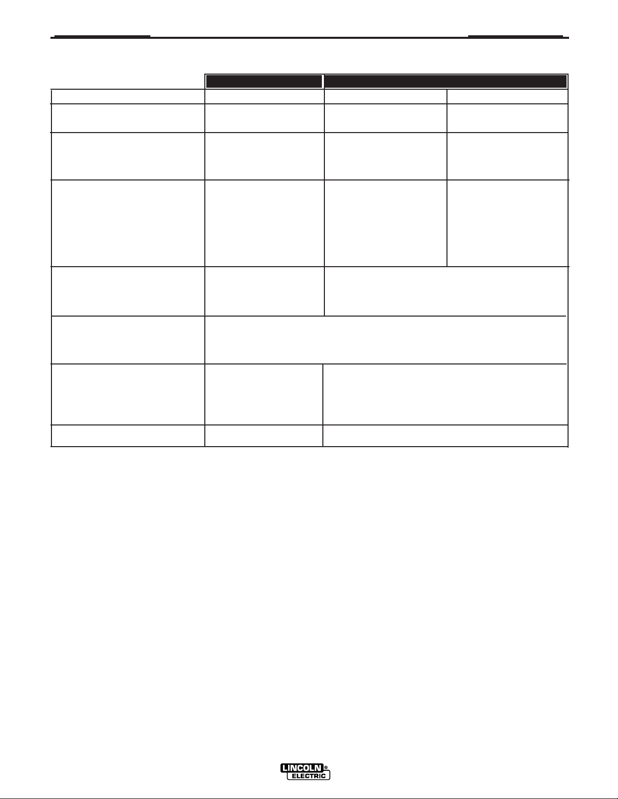
Troubleshooting..............................................................................................Section E
Safety Precautions.................................................................................................E-1
Troubleshooting Guide...........................................................................E-2 thru E-11
Procedure for Replacing PC Boards....................................................................E-12
Gun Cable Connector Requirements to Permit Proper Connection to Synergic 7F Wire Feed Units...........
E-12
Diagrams ..........................................................................................................Section F
Wiring.....................................................................................................................F-1
Input Connection....................................................................................................F-2
Dimension Prints ...........................................................................................F-3 - F-4
Parts Lists...............................................................................................................P-266
Page 8
A-1
INSTALLATION
TECHNICAL SPECIFICATIONS – SYNERGIC 7F AND SYNERGIC 7FH
A-1
Model
Type
Wire Speed Range:
IPM
M/M
Wire Size Capabilities:
Solid Electrodes
Cored Electrodes
Input Power:
Temperature Rating:
Operating
Storage
CONTROL
SYNERGIC 7F SYNERGIC 7F SYNERGIC 7FH
K678-2
40-42 V ± 10%
50/60 Hz
4.0 Amps
-20°C to +40°C
-40°C to +40°C
WIRE FEED - (4 - ROLL)
K679-1
50 - 770
1.25 - 19.5
.025 - 1/16”
0.6 - 1.6mm
.045 - 3/32”
1.2 - 2.4mm
K679-2
80 - 1200
2.00 - 30.5
.025 - .045”
0.6 - 1.2mm
.045”
1.2mm
Dimensions:
Height
Width
Depth
Weight
13.31” (338.1 mm)
10.32” (262.1 mm)
6.16” (156.5 mm)
13.25 lbs (6.0 Kg)
11.25” (285.8 mm)
7.16” (181.9 mm)
8.06” (204.7 mm)
16.5 lbs (7.5 Kg)
SYNERGIC 7F & FH
Page 9

A-2
GENERAL DESCRIPTION
INSTALLATION
b) Feeds .045 - 3/32” (1.2-2.4mm) cored wire for Outershield
GMA or Innershield processes up to 5/64” (2.0 mm).
The Synergic 7F is a CSA / NRTL/C certified semiautomatic
constant speed wire feeder designed specifically for use
The Synergic 7FH wire feed unit has the following
wire feeding capabilities:
with the Invertec Power Wave type power sources. This
boom or fixture mounting wire feeder consists of a Synergic
7F Control Box and the choice of the standard Synergic 7F
a) Feeds .025 - .045” (0.6-1.2mm) solid wire for
gas-metal-arc processes.
or High Speed Synergic 7FH wire feed unit and connecting
cable assemblies. A serial communication link is supplied
through the input control cable of the Synergic 7F enabling
b) Feeds .045 - (1.2mm) cored wire for Outershield
GMA or Innershield processes.
information to be shared between the power source and
wire feeder control. The 4-Roll Synergic 7F wire feed units
come factory equipped with gas solenoid valve with gas fittings and standard Lincoln gun connector and connector for
an optional dual procedure gun switch. Control includes a
Recommended power sources are The Lincoln
Electric Company Synergic type Invertec® power
sources with 42VAC auxiliary power, and a 14-pin
connector receptacle.
3-1/2 digit LED display with rotating knob encoder controls
for setting the wire feed speed and voltage. A tactile-feel
STANDARD FEATURES
keypad provides selection of operating mode, function
selection, timer and crater fill selection and parameter
Wire Feed Features:
adjustment. Two keys provide Cold Feed and Gas Purge
functions, and a connector receptacle is provided for an
optional dual procedure remote control.
Wire Drive Unit - Incorporates low voltage permanent
magnet motor and highly efficient two-reduction spur
gearbox with insulated mounting bracket for mounting
The unit has 3 operating modes: 2-step trigger, 4-step trigger and spot. Three functions can be selected: Volts or
and operation in any position. The non-fluid lubricant
won’t leak.
Trim Preset/arc (memory) voltmeter, Run-in speed and weld
speed (IPM or m/min.) or (memory) ammeter. In addition,
when 4-step trigger mode is selected, crater fill WFS is also
adjustable. In addition, when 4-step trigger mode is selected, crater fill WFS is also adjustable. Up to three timers are
available depending on the mode: preflow, postflow and
“Quick Release” Wire Feed System - Provides a
completely tool-less means for releasing and opening
the idle roll pressure arm, precisely adjusting the idle
roll pressure and changing the incoming and outgoing
guide tubes.
spot, and 5 acceleration rates are selectable, as well as 6
Burnback settings.
Drive Rolls and Guide Tubes - Provide long life,
positive feeding and precise alignment of electrode.
The K678-2 Synergic 7F control may be used with
either of the two available 4-roll wire feed units.
Ordering Speed Range Wire Size Range
Information Model Drive IPM (m/m) IN. (MM)
K679-1 Synergic 4-Roll 50 - 770 .025 - 3/32
7F (1.25 - 19.5) (0.6 - 2.4)
Minimizes “birdnest” or mill-thru of wire if properly set.
(Ordered separately.)
Tachometer Feedback - Provides proper wire feed
acceleration and speed accuracy, independent of fluctuations in line voltage and wire loading, for reliable
arc starting and weld consistency.
K679-2 Synergic 4-Roll 80 - 1200 .025 - .045
The feeder to control cable assemblies are available in two types:
K680-”L” Includes a control cable with a 14-pin MS style connector on each end, and a 4/0 weld
cable. Available in lengths “L” of 16ft (4.9m) or 25ft (7.6m).
K681-”L” Same as above but does not include weld cable available in lengths “L” of 12ft (3.6m),
16ft (4.9m) or 25ft (7.6m).
7FH (2.00 - 30.5) (0.6 - 1.2)
Run-in Speed Setting - Allows the arc striking speed
“Run-in” to be adjusted independently of the weld feed
speed for starting optimization.
Cold Feed Speed - Provides cold feed speed adjustment
independent of weld, run-in and crater speeds.
RECOMMENDED PROCESSES
AND EQUIPMENT
The Synergic 7F wire feed unit has the following wire
feeding capabilities:
a) Feeds .025 - 1/16” (0.6-1.6mm) solid wire for
gas-metal-arc processes.
Selectable Acceleration - Provides front panel selection of 5 acceleration rates. This feature in combination with Run-in Speed provides the ability to easily
optimize starting on any process or procedure.
Solid-State Dynamic Braking -
motor to minimize wire overrun during weld termination. Solid-state design requires no maintenance.
A-2
Quickly stops wire feed
SYNERGIC 7F & FH
Page 10

A-3
Crater Fill - Provides crater feed speed adjustment (in
4-step trigger mode) independent of weld, cold inch,
or run-in speeds.
Solid-State Overload Protection - No circuit breaker
to reset. Front panel display indicates time remaining
before automatic reset.
Gas Solenoid Valve - Complete with inlet fittings for
easy installation of gas is standard on Synergic 7F
models. Also available, as an option (K659-1), a Gas
Guard regulator for flow surge suppression.
English/Metric Speed Display - Provides front panel
selection of speed display in units of IPM or M/M.
INSTALLATION
A-3
2-Step or 4-Step Trigger Modes - Unit operates only
when trigger is pressed in 2-Step mode (normal) operation. 4-Step Trigger Mode eliminates the need to
hold the gun trigger closed while welding. Both models have user selectable 4-step with crater fill, or as
shipped, 4-step with current interlock.
Gas Preflow and Postflow Timers - Allows setting of
shielding gas preflow time (0-2.5 seconds) before
welding arc starts, and gas postflow time
(0-9.9 seconds), after welding arc stops.
Crater Fill - Allows setting of crater fill WFS (when 4step with crater fill trigger mode is selected), independent of weld, cold feed, and run-in speeds.
4-Roll Drive - Both models employ 4-Roll Drive, with
2 driven rolls, providing optimal feeding force for problem feeding situations, with low wire deformation for
improved feeding of soft wires.
Control Features:
Microcomputer Based Control - Provides precise
setting and display of all parameters and precision
timing functions. Optimizes wire drive control for crisp
acceleration and smooth response with precise
repeatability. Allows synergic control of various welding processes by communicating information over a
serial link to the compatible power source.
Display and Indicator Lights - Wide temperature
range, long life, 3-1/2 digit 7-segment LED display
with .56” (14.2mm) character height permits easy
viewing even from long gun cable distances.
Individual red indicator lights are high intensity LED’s
for viewing at almost any angle.
Encoder Controls - Rotating encoders provide continuous knob control for setting both Wire Feed Speed
and Volts/Trim procedures.
Procedure Switch - Permits selection of A or B procedures, as set by the procedure controls and memory pair selected at the Power Wave power source.
Setting switch to center “Gun Switch” position allows
selection of A or B procedures with the optional Dual
Procedure Switch.
Keypad - Consists of 7 membrane keys with tactilefeel embossed domes. All keys are generously
spaced to provide easy selection, even if wearing
welding gloves.
Selectable Burnback Time - Provides front panel
selection of 6 Burnback times. This feature provides
selectable Burnback time (default = 0ms) if required to
prevent electrode from sticking in weld puddle at finish
of weld.
Spot Mode - Allows a single timed weld cycle each
time the gun trigger is held closed. Duration (0.2-9.9
seconds) is set by the Spot ON timer.
Digital “Memory” Voltmeter - Displays arc voltage
from 0 to 80V DC, when welding gun trigger is activated, with automatic polarity indication for positive or
negative electrode. The last welding voltage monitored at end of weld is displayed for 5 seconds after
weld has stopped. This allows checking actual voltage after weld has stopped.
Digital “Memory” Ammeter - Weld Feed Speed
(WFS) display may be selectable to display welding
amps only while welding and the last welding amps
monitored at the end of the weld will be displayed for
5 seconds after the weld has stopped. This allows
checking actual weld current after the weld has
stopped.
Power-down Save - All settings, including mode,
Run-in speed, cold feed speed, crater speed, weld
speed, timers, English-Metric units and acceleration
are automatically saved when power is removed. This
feature does not require batteries and when power is
restored it will automatically return all settings to the
state they were in when power was removed.
However, the power source may overwrite any or all
of these parameters after Power-Up Recall is complete.
SYNERGIC 7F & FH
Page 11

A-4
INSTALLATION
KEYPAD AND DISPLAY
DESCRIPTION
Keypad - Seven key, membrane
COLD FEED GAS PURGE
TRIGGER MODE
2-STEP
STD
4-STEP
LOCK
SPOT
PREFLOW POSTFLOW
type with “snap” tactile feel and
embossed domes. Long life
design. Spatter resistant surface.
TRIM
VOLTS
/
V
Display - 3-1/2 digit 7-segment
RUN-IN
LED with (+) or (-) polarity indica-
WFS
tors. .56” (14.2mm) character
height. Displays arc voltage in
volts, wire speed in IPM or m/m and
2
1
all timers in seconds.
CRATER
SPOT
Indicator Lights - Extra bright red
LED’s for viewing at almost any
angle. Always indicates the mode
being used and which function or
timer is being displayed.
Cold Feed key energizes the wire
feeder but not the power source or
solenoid valve. Cold feed speed is
adjustable and is displayed only
while pressing Cold Feed, and the
last speed selected is stored in
memory for the next Cold feeding.
VOLTS
TRIM
V
PREFLOW POSTFLOW
1
/
RUN-IN
WFS
2
CRATER
SPOT
A-4
Function Select key enables operator to choose which
function will be displayed as shown by the appropriate
indicator light. Pressing the key causes lights to sequence
(top to bottom) starting from the current indicated position.
The function displayed will be adjustable with the rotating
encoder controls or arrow keys:
Adjusting either encoder knob automatically transfers display (and indicator light) to the function being adjusted.
Top Light - Indicates display of preset voltage or percent
trim when not welding and arc voltage while welding (as
indicated by top light “blinking”), and continues for 5 seconds after the weld has stopped (memory vpltmeter). The
power source automatically determines whether preset
voltage or percent trim will be displayed, and adjustable
with Volts/Trim rotating encoder control.
Middle Light - Indicates Run-in speed is being displayed.
As shipped, these models are setup for a 50 IPM
(1.27m/min) fixed run-in speed with display function deactivated. They may be user-selected to activate or deactivate adjustable Run-in display, and setting with arrow
keys.
Bottom Light - Indicates Weld Feed Speed (WFS) is being
displayed, and is adjustable with the Wire Feed Speed
rotating encoder control. If selected, this light will “blink”
while welding, indicating that the display has been selected to display welding amps, and continues for 5 seconds
after the weld is stopped (memory ammeter).
Timer/Crater Select
or gas timers, or crater speed as indicated by the appropriate light. Pressing the key causes lights to sequence
(left to right, top to bottom) starting from the current indicated selection. Any parameter not available in the mode
selected is skipped over.
key enables operator to choose spot
2-STEP
STD
4-STEP
LOCK
SPOT
Gas Purge
key energizes the solenoid valve but not the wire feeder or
power source.
Mode Select
key enables operator
to choose mode of operation shown
by the indicator lights. Pressing key
causes mode lights to sequence
(top to bottom) starting from the
current indicated selection.
Top Light - Indicates 2-step (standard) trigger mode.
Middle Light - Indicates 4-step
(lock) trigger mode. This mode may
be selected to include crater fill or
weld current interlock.
Bottom Light - Indicates spot weld
mode.
SYNERGIC 7F & FH
Top Left Light - indicates preflow time is being displayed in
seconds.
Top Right Light - indicates postflow time is being displayed in seconds.
Middle Light - indicates Crater Feed Speed is being displayed. This display will only occur if 4-step mode with
crater fill is selected.
Bottom Light - indicates spot on time is being displayed in
seconds.
Increase arrow key increases the setting of the parameter selected to be displayed. Arrow keys do not
function for Wire Feed Speed or Volts/Trim settings,
which are adjusted using the rotating encoder knobs.
Decrease
arrow key decreases the setting of the parameter selected to be displayed. Arrow keys do not
function for Wire Feed Speed or Volts/Trim settings,
which are adjusted using the rotating encoder knobs.
Page 12

A-5
INSTALLATION OF THE SYNERGIC 7F COMPONENTS
INSTALLATION
door screws.
c) Mount the box.
Safety Precautions
d) Tighten the screws.
e) Close the control box door and replace the door
screws.
WARNING
ELECTRIC SHOCK can kill.
• Do not touch electrically live parts such
as output terminals or internal wiring.
•
When inching with gun trigger, electrode and
drive mechanism are “hot” to work and
ground and could remain energized several
seconds after the gun trigger is released.
• Turn OFF input power at welding power
source before installation or changing
drive roll and/or guide tubes.
• Welding power source must be connected
to system ground per the National
Electrical Code or any applicable local
codes.
• Only qualified personnel should
perform this installation.
Observe all additional Safety Guidelines detailed
throughout this manual.
Mounting the Wire Feed Unit (K679-1 or -2)
Mount the wire feed unit by means of the insulated
mounting bracket attached to the bottom of the gearbox. Reference L9777 dimension print at the rear of
this manual to find the size and location of the mounting holes. The gearbox assembly is electrically “hot”
when the gun trigger is pressed. Therefore, make certain the gearbox does not come in contact with the
structure on which the unit is mounted.
The wire feed unit should be mounted so that the
drive rolls are in a vertical plane so dirt will not collect
in the drive roll area. Position the mechanism so it will
point down at about a 45° angle so the wire feed gun
cable will not be bent sharply as it comes from the
unit.
Connecting Wire Feed Unit to Control Box
The Feeder to Control cable assemblies are available
in two types:
K680-”L” Includes a control cable with 14-pin MS-
K681-”L” Same as K680, but does not include
1. Making certain the cables are protected from any
sharp corners which may damage their jackets,
mount the cable assembly along the boom so the
end with the female MS-style connector pins is at
the wire feed unit.
2. Connect the 14-socket cable connector to the
receptacle on the back of the wire feed unit connection box.
3. At the same end, connect the electrode lead to the
connection stud of the brass gun connection block
on the front of the wire feed unit.
4. At the control box end, connect the 14-pin connector of the cable to the mating receptacle on the
bottom of the control box.
Electrode Routing
The electrode supply may be either from reels, ReadiReels, spools or bulk packaged drums or reels.
Observe the following precautions:
A-5
style connectors on each end, and a 4/0
weld cable to route between the Wire
Drive and the Control Box. Available in
lengths “L” of 16ft. (4.9m) and 25ft.
(7.6m).
weld cable. Available in lengths “L” of
12ft. (3.6m), 16ft. (4.9m) and 25ft.
(7.6m).
Mounting the Control Box (K678-2)
The same control box is used for both the Synergic 7F
and Synergic 7FH wire feed units and contains two
keyhole slots and one slot for mounting. Reference
M17740 dimension print in the rear of this manual for
size and location of these slots. Mount the box at
some convenient location close to the wire feed unit
which will enable the desired control cable assembly
to reach between the control box and the wire feed
unit.
a) Drill the required holes in the mounting surface,
partially install 1/4-20 screws.
b) Open the control box door by removing the two
SYNERGIC 7F & FH
1. The electrode must be routed to the wire feed unit
so that the bends in the wire are at a minimum,
and also that the force required to pull the wire
from the reel into the wire feed unit is kept at a
minimum.
2. The electrode is “hot” when the gun is energized
and must be insulated from the boom and structure.
3. If more than one wire feed unit shares the same
boom, their wire and reels must be insulated from
each other and insulated from their mounting
structure.
Page 13
A-6
INSTALLATION
A-6
Wire Feed Drive Roll and Guide Tube Kits
NOTE: The maximum sizes the Synergic 7F will feed
satisfactorily are the 3/32” (2.4mm) cored and
1/16” (1.6mm) solid electrodes. The maximum
sizes the synergic 7FH will feed satisfactorily
are the .045 (1.2mm) cored and .045” (1.2mm)
solid electrodes.
The electrode sizes that can be fed with each
roll and guide tube are stencilled on each part.
Check the kit for proper components.
Steel Wire Sizes:
* .068 - 3/32” (1.7 - 2.4mm) Cored KP655-3/32
* 1/16” (1.6mm) Cored or Solid KP655-1/16
.045 - .052” (1.2 - 1.4mm) Solid KP655-052S
.045 - .052” (1.2 - 1.4mm) Cored KP655-052C
.035” (0.9-1.0mm) Cored KP655-035C
.035” (0.9-1.0mm) Solid KP655-035S
.030” (0.8mm) Solid KP655-030S
.023” (0.6mm) Solid KP655-025S
4-Roll
PROCEDURE TO INSTALL DRIVE
ROLL AND GUIDE TUBES
WARNING
ELECTRIC SHOCK can kill.
• Do not touch electrically live parts such
as output terminals or internal wiring.
•
When inching with gun trigger, electrode and
drive mechanism are “hot” to work and
ground and could remain energized several
seconds after the gun trigger is released.
• Turn OFF input power at welding power
source before installation or changing
drive roll and/or guide tubes.
• Welding power source must be connected
to system ground per the National
Electrical Code or any applicable local
codes.
• Only qualified personnel should
perform this installation.
Observe all additional Safety Guidelines detailed
throughout this manual.
Aluminum Wire Sizes:
1/16” (1.6mm) KP656-1/16A
KP647-1/16A**
3/64” (1.2mm) KP656-3/64A
KP647-3/64A**
.040” (1.0mm) KP647-040A**
.035” (0.9mm) KP656-035A
Drive rolls for only cored
electrode sizes are stencilled
with a “C” suffix to the wire sizes.
Drive rolls for only solid electrode sizes are stencilled
with an “S” suffix to the wire sizes.
Drive rolls for aluminum wire sizes are stencilled with an
“A” suffix to the wire sizes.
* Not for Synergic 7FH model.
** For use with Binzel European guns. Installation
instructions are included with these kits. Also
requires K489-2 Fast-Mate Adapter.
Standard 4-Roll Kits (KP655 and KP656)
1) Turn off welding power source.
2) Release both quick release levers by sliding the
levers sideways into the open positions.
Remove clamping screw & clamping collar from the
3)
drive shaft closest to the incoming side of the feeder.
4) Install drive roll onto keyed shaft. (Do not exceed
the maximum wire size rating of the wire drive.)
Replace collar and tighten clamping screw.
5) Back out the set screw for the middle guide tube.
Install the middle guide tube and slide it up against
the drive roll. DO NOT TIGHTEN THE MIDDLE
GUIDE AT THIS TIME.
6) Install the outgoing drive roll following the same
procedure as steps 3 & 4.
7) Center the middle guide between the two drive rolls
and tighten in place.
8) Back out the screws for the incoming and outgoing
guide tubes.
SYNERGIC 7F & FH
Page 14

A-7
INSTALLATION
A-7
9) Install the longer guide tube in the rear hole near
the incoming drive roll. Slide the tube in until it
almost touches the roll. Tighten in place.
10) Install the remaining guide tube in the front hole.
Be certain that the proper plastic insert is used.
Fine wire chisel point tube must
radius next to drive roll. Tighten in place.
11) Re-latch both quick release levers.
12) To start new electrode, straighten the first
6” (150mm) and cut off the first 1” (25mm). Insert
free end through the incoming tube. Press gun
trigger & push wire into the drive roll.
TO SET IDLE ROLL PRESSURE: See Idle Roll
Pressure Setting, in “Operation” section.
have largest
Gun and Cable Assemblies with Standard
L. E. Connections
GMAW Guns
An expanding line of Magnum gun and cable assemblies are available to allow welding with solid and
cored electrodes using the GMAW process. See the
appropriate Magnum literature for descriptions of the
200 to 550 ampere air cooled gun and cables that are
available. Gun cable lengths range from 10 ft (3.0m)
to 25 ft (7.6m) and feed electrode sizes .025” (0.6mm)
to 5/64” (2.0mm). The entire line of Magnum FastMate gun and cable assemblies can also be used by
installing a K489-2 Fast-Mate adapter kit.
INNERSHIELD Guns
K126 and K115 gun and cable assemblies are available to allow welding with Innershield electrodes. Gun
cable lengths range from 10 ft. (3.0 m) to 15 ft. (4.5
m). The 350 ampere K126 with Synergic 7F will feed
electrode sizes .062” (1.6 mm) to 5/64” (2.0 mm). The
450 ampere K115 with Synergic 7F will feed 5/64” (2.0
mm) electrode.
Three smoke extraction gun and cable assemblies are
available, 250 ampere K309, 350 ampere K206 and
the 500 ampere K289. All gun and cable lengths are
15 ft. (4.5 m). Both the K206 and K309 with Synergic
7F will feed electrode sizes .062” (1.6 mm) to 5/64’
(2.0 mm). K289 with Synergic 7F will feed 5/64” (2.0
mm) electrode. These guns require the use of the
K184 vacuum unit for use with Synergic 7F.
Gun Cable Connection:
Lay the cable out straight. Insert the connector on the
welding conductor cable into the brass conductor
block on the front of the Synergic 7F gearbox. Make
sure it is all the way in and tighten the hand wheel.
Keep this connection clean and bright. Connect the
trigger control cable polarized plug into the mating 5
cavity receptacle on the front of the Synergic 7F Wire
Feed Unit.
For GMA Gun Cables:
Install the barbed fitting and union nut to the 5/8-18
female inert gas fitting on the front of the Synergic 7F
wire drive. Connect the 3/16” I.D. gas hose from the
gun cable to the barbed fitting. When the gun is to be
removed, this fitting can be easily detached by loosen-
ing the union nut.
Gun and Cable Assemblies with Fast-Mate
Connections (Requires K489-2 Fast-Mate Adapter
Kit)
GMAW Guns
An expanding line of Magnum Fast-Mate™ air cooled
and water cooled gun and cable assemblies are available to allow welding with solid and cored electrodes
using the GMAW process. See the appropriate
Magnum literature for descriptions of the 200 to 400
ampere air cooled gun and cables that are available,
as well as the Magnum “Super Cool” 450 ampere
water cooled gun and cable. Gun cable lengths range
from 10 ft (3.0m) to 25 ft (7.6m) and feed electrode
sizes .025” (0.6mm) to 5/64” (2.0mm).
An expanding line of Magnum X-Tractor gun and
cable assemblies provides fume extraction capability
for welding with solid and cored electrodes using the
GMAW process. See the appropriate Magnum literature for descriptions of the 250 to 400 ampere air
cooled gun and cables that are available. Gun cable
lengths range from 10 ft (3.0m) to 15 ft (4.5m) and
feed electrode sizes .035” (0.9mm) to 1/16” (1.6mm).
These guns require the use of either the K173-1 or
#
K184
vacuum units.
#
Requires S14927-8 connector hose and an S20591
hose adapter.
SYNERGIC 7F & FH
Page 15
A-8
INSTALLATION
A-8
Gun Cable Connections: Wire Feeder
to Gun
a. Check that the drive rolls, feeder guide tubes and
gun connector guide tube are appropriate for the
electrode size being used. If necessary, change
them per the section on “Wire Feed Drive Roll and
Guide Tube Kits”.
b. Connect gun to gun connector making sure all pins
and gas tube line up with appropriate holes in connector. Tighten gun by turning large nut on gun
clockwise.
Synergic 7F Water Connections (for
Water-Cooled Guns)
The Synergic 7F models must have a K682-2 Water
Connection Kit installed. (see section under Optional
Features Installation; Water Connection Kit.
1)
Using hose clamps provided with the K682-2 Kit, connect appropriate water hoses to the coolant inlet and
outlet fittings on the back of the K682-2 Kit. Connect
the other ends of the hoses to the appropriate ports on
the water cooling units.
2)
In the event the water line fittings on your water-cooled
gun are incompatible with the female quick connects
on the front of the K682-2 Kit, male quick connects are
provided with the kit for installation on 3/16” (5mm) I.D.
hose (Customer to provide appropriate clamps). The
feeder connectors self seal when
disconnected.
GMAW Shielding Gas
WARNING
CYLINDER may explode if damaged.
• Keep cylinder upright and chained to
support.
• Keep cylinder away from areas where
it may be damaged.
• Never lift welder with cylinder attached.
• Never allow welding electrode to touch cylinder.
• Keep cylinder away from welding or other live electrical circuits.
BUILDUP OF SHIELDING GAS may
harm health or kill.
• Shut off shielding gas supply when not
in use.
SEE AMERICAN NATIONAL STANDARD Z-49.1,
“SAFETY IN WELDING AND CUTTING” PUBLISHED
BY THE AMERICAN WELDING SOCIETY.
------------------------------------------------------------------------
Customer must provide a cylinder of shielding gas, a
pressure regulator, a flow control valve, and a hose
from the flow valve to the gas inlet fitting of the
Synergic 7F Wire Feed Unit.
Connect a supply hose from the gas cylinder flow
valve outlet to the 5/8-18 female inert gas fitting on the
back panel of the Synergic 7F or, if used, on the inlet
of the Gas Guard regulator. (See Below).
Gas Guard Regulator - The Gas Guard Regulator is
an optional accessory (K659-1) on these models.
Install the 5/8-18 male outlet of the regulator to the
5/8-18 female gas inlet on the back panel of the
Synergic 7F. Secure fitting with flow adjuster key at
top. Attach gas supply to 5/8-18 female inlet of regulator per instructions in the “Gas Connections” Section.
SYNERGIC 7F & FH
Page 16

A-9
INSTALLATION
A-9
ELECTRICAL INSTALLATION
WARNING
ELECTRIC SHOCK can kill.
• Do not touch electrically live parts such
as output terminals or internal wiring.
•
When inching with gun trigger, electrode and
drive mechanism are “hot” to work and
ground and could remain energized several
seconds after the gun trigger is released.
• Turn OFF input power at welding power
source before installation or changing
drive roll and/or guide tubes.
• Welding power source must be connected
to system ground per the National
Electrical Code or any applicable local
codes.
• Only qualified personnel should
perform this installation.
Observe all additional Safety Guidelines detailed
throughout this manual.
Input Cable: Synergic 7F Control to Power Wave
Synergic Type Power Sources
NOTE: CSAnrtl certification of the Synergic 7 models is with
input cable assemblies identified by carton date codes
010161, or above. These assemblies have grounding lead
continituity between the 14-pin plug pin B and the 8-socket
plug pin E per diagram below.
B=GND
K643 (Control Cable Extension) - Consists of an 8
conductor control cable with 14-pin connectors on
each end for extending the control cable between the
power source and the control cables. Available in
lengths of 17 ft (5 m), 25 ft (8 m), 33 ft (10 m) and 50
ft (15 m).
With input power disconnected from the power
source, install the input cable per connection diagram
S22015 in the rear of this manual and follow exactly
the instructions on the diagram or perform the following:
1) Connect the end of the control cable with the 14pin cable plug to the mating receptacle on the
power source.
2) Connect the electrode lead of that same cable end
to the power source output terminal of the desired
polarity.
3) Connect the 14-socket plug of the control cable to
the mating receptacle on the bottom of the control
box.
4) If not using a single continuous electrode cable
from the Power Source to the Wire Feed Unit, bolt
the electrode lead from the power source to the
electrode lead to the wire feed unit using the nut
and bolt supplied with the K680 Control to Feed
Unit cable assembly. Insulate connection with electrical tape.
E=GND
14-PIN PLUG, FRONT VIEW
K648 - (Used with Power Wave 450) Consists of an 8-conductor control cable with a 14-pin plug and a 4/0 (107 mm
electrode cable with stud terminal. It is rated at 500 amps,
60% duty cycle and is available in lengths of 7 ft (2 m), 17 ft
(5 m), 25 ft (7.6 m), 33 ft (10 m) and 50 ft (15 m).
K649 - (Used with Power Wave 450/500)
conductor control cable with a 14-pin control cable plug and a
4/0 (107mm2) electrode cable with Twist-Mate™ connector. It
is rated at 500 amps, 60% duty cycle and is available in lengths
of 7 ft (2 m), 17 ft (5 m),
m).
25 ft (7.6 m),
8-PIN PLUG, FRONT VIEW
Consists of an 8-
33 ft (10 m) and 50 ft (15
2
)
K642 (Control Cable Only) - Consists of an 8
conductor control cable with a 14-pin control cable
plug, without electrode cable, and is available in
lengths of 7 ft (2 m), 17 ft (5 m), 25 ft (7.6 m), 33 ft (10
m) and 50 ft (15 m).
Work Cable
Connect a work lead of sufficient size and length (per
the following table) between the proper output terminal on the power source and the work. Be sure the
connection to the work makes tight metal-to-metal
electrical contact.
Current
Copper Work Cable Size, AWG *
60% Duty
Cycle
300 Amps
400 Amps
500 Amps
* For pulse welding applications, the next larger cable
size is recommended.
Up to 100 ft Length (30m)
00 (67 mm2)
000 (85 mm2)
000 (85 mm
2
)
SYNERGIC 7F & FH
Page 17

A-10
OPTIONAL FEATURES
INSTALLATION
INSTALLATION
A-10
K648, K649 or K642 Input Cable Assembly - See
Electrical Installation section for instructions.
K299 50-60 Lb. Wire Reel for Customer Mounting -
The K299 is available for use with the Synergic 7F
Wire Feed Models. The reel for 50 or 60 pound coils is
shipped with the needed mounting shaft, hardware,
and insulation. Shaft mounting hole requirements are
shown below:
K1449-1 Dual Procedure Remote Control Provides
remote rotating knob encoder control of Wire Feed
Speed and Volts/Trim, along with a dual procedure
selector switch, which disables comparable front panel
controls when the remote control is connected.
The 4-pin plug of the remote control connects to the
mating receptacle on the bottom of the Synergic 7F
Control box.
The K1450-”L” Extension cable is used to extend the
16 ft (5m) cable attached to the remote control.
Lengths “L” are available to match the Length of the
control to feeder cable being used.
K683-1 - Dual Procedure Switch
Switch mounts to gun with appropriate bracket, provided, per the installation instructions included with the
kit. 3-pin switch cord plug connects to 3-pin remote
receptacle on the front panel of the Synergic 7F Wire
Feed Unit.
K682-2 Water Connection Kit
of Wire Feed Unit mounting bracket per instructions
shipped with kit.
K659-1 Gas Guard Regulator - Adjustable flow regulator with removable adjustor key for CO
blend gases. Mounts onto Wire Feed Unit inlet and
reduces gas waste and arc start “blow” by reducing
surge caused by excess pressure in supply hose.( See
Shielding Gas Connections for instructions).
Dual Procedure
- Install to either side
2
and Argon
SYNERGIC 7F & FH
Page 18

B-1
OPERATION
B-1
OPERATING INSTRUCTIONS
Safety Precautions
WARNING
ELECTRIC SHOCK can kill.
• Do not touch electrically live parts such
as output terminals or internal wiring.
•
When inching with gun trigger, electrode and
drive mechanism are “hot” to work and
ground and could remain energized several
seconds after the gun trigger is released.
• Turn OFF input power at welding power
source before installation or changing
drive roll and/or guide tubes.
• Welding power source must be connected
to system ground per the National
Electrical Code or any applicable local
codes.
• Only qualified personnel should
perform this installation.
Observe all additional Safety Guidelines detailed
throughout this manual.
Duty Cycle
The Synergic 7F models are rated at 60% duty cycle *
for a maximum current of 600 amps.
* Based on a 10 minute time period (6 minutes on, and 4 minutes off).
KEYPAD SETUP AND OPERATION
Power-Down Save
Power to the Synergic 7F is supplied and controlled
from the power source. The Synergic 7F automatically senses the loss of power when the power source is
turned off.
Procedure settings, including mode, crater speed,
cold feed speed , run-in speed, weld speed, timers
and acceleration are automatically saved when power
is removed. Arc Voltage setting is retained by the
synergic power source. This feature does not require
batteries and when power is restored it will automatically return all settings to the state they were in when
power was removed. The power source may automatically overwrite any or all of these settings following power-up recall.
Operation Keys
Cold Feed key energizes the wire
feeder but not the power source or
solenoid valve. This cold feed
speed is digitally displayed and is
COLD FEED
GAS PURGE
adjustable (with “Arrow keys”) only
while pressing the Cold Feed Key.
The last setting is held in memory
for next Cold Inch feeding.
Gas Purge
key energizes the solenoid valve but not the wire feeder or
power source.
2-STEP
STD
4-STEP
LOCK
SPOT
SYNERGIC 7F & FH
Mode Selection
Mode Select
key enables operator
to choose mode of operation shown
by the indicator lights. Pressing key
causes mode lights to sequence
(top to bottom) starting from the
current indicated position.
Top Light
- Indicates 2-Step
(Standard) Trigger Mode.
1. Trigger closure energizes the
solenoid valve, then the wire feeder
and the power source after Preflow
time (See Timer/ Crater Section).
2. Releasing the trigger turns off the
wire feeder and power source and
then the solenoid valve after
Postflow time.
Middle Light - Indicates 4-Step (Lock)
Trigger Mode. These models have selectable
4-step with crater fill or, as shipped, 4-step
with current interlock. (See 4-step trigger
mode selection for method of switching).
The 4-step modes function as follows:
1. Trigger closure energizes the power
source and wirefeeder after the preflow time.
2. Trigger release enables 4-step lock,
leaving the feeder and power source
as in step 1.
a) 4-step with current interlock will only
lock if weld current is flowing.
Breaking weld arc stops wire feed
and power source output.
b) 4-step with crater fill will lock without
welding.
3. Closing the trigger a second time
continues welding.
a) 4-step with current interlock contin-
ues welding without changing the
settings from step 2.
b) 4-step with crater fill continues weld-
ing but changes to the crater settings.
4. Releasing the trigger turns off
wirefeeder and power source and
then gas solenoid after postflow
time.
Bottom Light - Indicates Spot Weld
Mode. Trigger closure energizes the
solenoid valve, then wire feeder and
the power source. The spot on timer
starts when current flows. The wire
feeder and power source then solenoid valve are all turned off when the
spot on timer times out even through
the trigger is still closed.
Page 19

B-2
V
VOLTS
OPERATION
Display Control Keys
The function select, timer/crater
select, arrow keys and rotational
encoders all effect the display.
Pressing the function select key will
cause a function to be displayed.
Pressing the timer/crater select key
will cause a timer or crater feed
speed to be displayed. Whichever
is pressed last is the one that will
be displayed since they cannot be
displayed simultaneously. Only
one function or timer indicator light
can be on at one time and therefore
it always indicates what is being
displayed. The arrow keys allow
you to adjust the Run-in speed
timer or crater speed being displayed. The encoder knobs allow
rotational adjustment of weld wire
feed speed and Arc Volts/Trim.
Note: If an indicator light is skipped, that
parameter may not be enabled. Refer to
section covering that parameter.
Function Select key enables oper-
TRIM
/
ator to choose which function will
be displayed as indicated by the
RUN-IN
appropriate light. Pressing the key
causes lights to sequence (top to
WFS
bottom) starting from the current
indicated position. If a timer or
crater speed is being displayed
when the Function Select key is
pressed, then the indicator light of
the last function selected before the
timer/crater key was chosen will
come on and become the starting
point for the sequencing.
Adjusting either encoder knob automatically transfers display (and indicator light)
to the function being adjusted (Volts/Trim
or Wire Feed Speed).
Top Light - indicates Voltmeter
Function has been selected and arc
voltage (in volts) will be displayed
along with electrode polarity when
the trigger has been pressed.
When the trigger is not pressed,
this will serve as a preset
voltage/trim function and the preset
voltage/trim will be displayed. The
top light “blinks” when arc voltage is
being displayed and stays lit when
preset voltage/trim is displayed.
The last welding voltage displayed
before the weld is stopped, will continue to be displayed for 5 seconds
B-2
after welding to permit operator monitoring.
The preset voltage/trim may be adjusted,
using the Volts/Trim encoder knob. The synergic preset voltage/trim level may be adjusted within the range synergically set by the
power source for the process and weld Feed
Speed being used.
matically determines whether preset voltage or percent trim will be displayed.
Preset voltage is indicated by one digit only
to the right of the decimal point, while percent trim always displays two digits to the
right of the decimal point.
Middle Light
Function has been selected and the Run-In
speed setting is being displayed in IPM or
m/m (see section for English or Metric display).
As shipped these models are setup for
minimum rated fixed Run-In speed with display function deactivated. They may be
user-selected to activate or deactivate
adjustable Run-In display. (See section for
selection of Run-In and resetting fixed RunIn speed).
Wire will be fed at the Run-In speed rate
until arc current begins to flow. Once arc
current flows, wire will be fed at the Weld
speed rate. Decreasing Run-In speed
below its lower limit (using the down arrow
key) causes the display to read “- - -”. This
indicates that the Run-In speed will be kept
the same
can reset a different Run-In speed simply
by pressing the up arrow key.
The Run-In speed will also be the same
the weld speed setting if rapid restrike
welding applications are used, where the
arc is restruck in a fraction of a second
after the previous welding arc was stopped.
Bottom Light
Speed (WFS) Function has been selected
and the weld speed setting is being displayed in IPM or m/m (see section for
English or Metric speed display). The
range of Weld Feed Speed is synergically
set by the power source for the process
being used, and is adjustable using the
Wire Feed Speed encoder knob on the
front of the Synergic 7F Control.
If selected (see Memory Ammeter
Selection section), the bottom light will
“blink” while welding, indicating that the display has been selected to display welding
amps. The last welding current displayed
before the weld is stopped will continue to
be displayed for 5 seconds after welding to
permit operator monitoring.
as the weld speed setting. You
The power source auto-
- Indicates Run-In Speed
as
- Indicates Weld Feed
SYNERGIC 7F & FH
Page 20

B-3
PREFLOW POSTFLOW
2
1
CRATER
SPOT
OPERATION
Timer/Crater Select - key enables
operator to choose crater speed, spot
or gas timers as indicated by the appropriate light. Pressing key causes lights
to sequence (left to right, top to bottom)
starting from the current indicated position. Any parameter not available in the
mode selected is skipped over. If a
function is being displayed when the
Timer/Crater Select key is pressed,
then the light of the last parameter
selected before the function was chosen will come on and become the starting point for the sequencing.
Top Left Light
is being displayed in seconds. This is
the time the shielding gas flows before
the wire feed and power source are
activated.
Top Right Light
time is being displayed in seconds.
This is the time the shielding gas flows
after the wire feed and power source
are deactivated.
Middle Light
speed is being displayed. Crater speed
is only available when 4-step trigger
with crater fill is selected. (See 4-step
trigger mode selection section). It is
activated by Step 3 and deactivated by
Step 4 of the 4-step sequence.
Bottom Light
being displayed in seconds.
NOTE: if unit is not
this light will be skipped over in the
selection sequence.
Increase Arrow - key increases the
setting of the parameter selected to be
displayed, except Wire Feed Speed and
Volts/Trim which are controlled by the
encoder knobs.
Decrease Arrow - key decreases the
setting of the parameter selected to be
displayed, except Wire Feed Speed and
Volts/Trim which are controlled by the
encoder knobs.
Arrow Keys use the “Accelerating
Digit” method for setting changes,
where holding the arrow key causes
setting change rate to accelerate from
slow to fast. Releasing arrow key resets
to slow setting change.
- indicates preflow time
- indicates postflow
- indicates that crater feed
- indicates spot on time is
in spot mode then
GAS PURGE
VOLTS
TRIM
/
V
RUN-IN
WFS
GAS PURGE
PREFLOW POSTFLOW
GAS PURGE
COLD FEED
2
1
CRATER
SPOT
B-3
Acceleration Selection
Pressing both the “Gas Purge” key and then the
function select key at the same time causes the
acceleration setting to be displayed. The display
will indicate “A-X” where X will be a number from
1 through 5 with 5 being the fastest acceleration.
This number can be adjusted using the arrow
keys. To exit this function, press both
again or press any other key except the arrow
keys.
Burnback Time Selection
If necessary, for higher wire feed speeds,
Burnback time may be selected to prevent the
electrode from sticking in the weld puddle at the
end of the weld. Pressing both the Gas Purge key
then the function select key at some time while
displaying the acceleration setting per above,
press the function select key a second time to display the Burnback time selection. Default is “b0”
which is zero delay. Selecting “b1" thru “b5"
selects delays from 10m sec to 50m sec in 10m
sec increments. To exit this function, press both
these keys again or press any other key except
the arrow keys.
Selection of English or Metric Speed
Display Units
Pressing both the Gas Purge key and then
timer select key at the same time causes the
speed display units to toggle between IPM
(no decimal point displayed) and m/m (a
decimal point displayed). If the speed display units were IPM, then they will change to
m/m. If the speed display units were m/m,
then they will change to IPM. If the display
is showing the volts/trim or one of the timers
when the keys are pressed, the display will
be changed to weld speed to indicate the
selected speed display units.
Run-In Selection
Pressing both the Gas Purge and Cold Feed
keys at the same time causes Run-In function to toggle on or off, as indicated by the
Run-In indicator light turning on or remaining
off in the function select sequence.
As shipped, the Run-In function is off with a
fixed setting of min. rated speed. Therefore,
the Run-In indicator light will not sequence
with the function select key, but the fixed
setting will still be used for actual Run-In
speed.
Activation of adjustable Run-In speed using
the above dual key press, will permit Run-In
speed to be adjusted with the arrow keys
and the Run-In indicator light will return to
the function key sequence. Re-pressing the
above dual key again removes the Run-In
light from the function key sequence, but
replaces the fixed Run-In speed with the
adjusted Run-in speed setting, until readjusted.
these keys
SYNERGIC 7F & FH
Page 21

B-4
OPERATION
B-4
GAS PURGE
2-STEP
STD
4-STEP
LOCK
SPOT
GAS PURGE
4-Step Trigger Mode
Dual Procedure Remote Control (K1449-1)
Selection
Pressing both the Gas Purge key
and then the Trigger mode select
key causes the 4-step mode light to
turn on and will toggle the 4-step
trigger mode between:
4-step with current interlock (as shipped)
Crater light will not turn on.
and
4-step with crater fill.
Crater light will turn on for crater speed set-
ting with arrow keys.
(See Mode Selection and Display
Control Keys sections).
Memory Ammeter Selection
Pressing both the Gas Purge key
then the Up Arrow key at the same
time causes the WFS light to “blink”
for about 3 seconds while display
shows weld amps reading with electrode polarity symbol. This indicates
that while welding, the display will
show welding amps, indicated by
“blinking” WFS indicator light, which
continues for 5 seconds after the
weld is stopped (memory ammeter)
before returning to displaying WFS
(light not “blinking”.)
Pressing both the Gas
Purge and Up Arrow key again,
returns WFS display to wire speed
When this option is connected to the feeder control
receptacle the front panel knob controls are disabled
and procedure control is transferred to the knob
encoder controls of the remote, which function in the
exact same manner.
NOTE: The dual procedure overlay must be present on the Power Wave power source for the
Procedure Selector switch to function. If this
overlay is not used, only Procedure A will be
selected no matter what position the Procedure
switch is in.
The procedure selector switch on the remote functions
the same as that on the front panel when the front
panel procedure selector switch is set to “Gun Switch”
position. Likewise, if the remote procedure selector
switch is also set to “Gun Switch” position the optional
K683-1 Dual Procedure switch may be used to select
A or B procedures.
Procedure Selector Switch
The toggle switch on the front panel provides selection
of Procedure A or Procedure B, as set with the front
panel knob controls. Rotating the knob encoder
changes only the procedure selected by this switch.
Also, this switch selects the A or B memory pair selected at the Power Wave power source.
NOTE: The dual procedure overlay must be present
on the Power Wave power source for the Procedure
Selector switch to function. If this overlay is not
used, only Procedure A will be selected no matter
what position the Procedure switch is in.
Setting the toggle switch to the center “Gun Switch”
position permits the Procedure A or Procedure B to be
selected by the optional K683-1 Dual Procedure
Switch. The K1449-1 Dual Procedure Remote Control
can be used with this panel Procedure Switch in any
position.
SYNERGIC 7F & FH
Page 22

B-5
Brake Holding Pin
(Must engage hole
in adapter rib)
GROOVES
2" O.D. SPINDLE
PIN
MOLDED ADAPTER
RETAINING SPRING
OPERATION
To Mount 10 to 44 lb (4.5-20kg) Spool
(12”/300mm Diameter): (Requires installation
of 2” (51mm) spindle K162H Kit. For 8” (200mm)
spools, a K468 spindle adapter must be used.)
1) Remove the locking collar on the 2” (51mm) diameter spindle.
B-5
Installation of K363-P Readi-Reel Adapter
READI-REEL
INSIDE CAGE WIRES
THREADED LOCKING COLLAR
Wire Reel Loading - Readi-Reels and
Spools (Using K162H Spindle Kit with 2”
(51mm) spindle)
TO MOUNT A 30 LB (14 kg) READI-REEL
PACKAGE USING THE MOLDED PLASTIC K363-P
TYPE ADAPTER:
1) Make certain that the threaded locking collar is
tight and securely locks the adapter on the spindle
(see figure above).
2) Rotate the spindle and adapter so the retaining
spring is at the 12 o’clock position.
3) Position the Readi-Reel so that it will rotate in a
clockwise direction when feeding (wire is to be dereeled from bottom of the coil).
4) Set one of the Readi-Reel inside cage wires on the
slot in the retaining spring tab.
5) Lower the Readi-Reel to depress the retaining
spring and align the other inside cage wires with
the grooves in the molded adapter.
6) Slide cage all the way onto the adapter until the
retaining spring “pops up” fully.
2) Place the spool on the spindle making certain the
brake holding pin enters one of the holes in the
back side of the spool. Be certain the wire comes
off the reel in a clockwise direction when de-reeled
from the bottom of the coil.
3) Replace and tighten the locking collar.
Feeding Electrode and Brake Adjustment
1) Turn the Readi-Reel or spool until the free end of
the electrode is accessible.
2) While tightly holding the electrode, cut off the bent
end and straighten the first 6” (150mm). Cut off
the first 1” (25mm). (If the electrode is not properly
straightened, it may not feed or may not go into
the outgoing guide tube causing a “birdnest”.)
3) Insert the free end through the incoming guide
tube.
4) Press the Cold Inch key or the gun trigger and
push the electrode into the drive roll.
WARNING
When feeding with the gun trigger, the electrode and
drive mechanism are always “HOT” to work and
ground and could remain “HOT” several seconds after
the gun trigger is released.
___________________________________________
5) Feed the electrode through the gun.
WARNING
Check to be sure the Retaining Spring has fully
returned to the locking position and has SECURELY
locked the Readi-Reel Cage in place. Retaining
Spring must rest on the cage, not the welding electrode.
___________________________________________
7) To remove Readi-Reel from Adapter, depress
retaining spring tab with thumb while pulling the
Readi-Reel cage from the molded adapter with
both hands. Do not remove adapter from the
spindle.
SYNERGIC 7F & FH
6) Adjust the brake tension with the thumbscrew on
the spindle hub, until the reel turns freely but with
little or no overrun when wire feeding is stopped.
Do not overtighten.
Page 23

B-6
OPERATION
Wire Reel Loading - 50-60lb (22.7-27.2kg)
Coils (K299 Wire Reel Mounting Kit)
Adjustable Wire Reel Brake
The mount for standard 50-60 lb (22.7-27.2 kg) electrode coils includes a two-position brake assembly.
Generally the brake should be at the inner position
(nearest to the wire reel shaft) for wire feed speeds
below 400 in/min. (10m/m). It should be at the outer
position for the faster wire speeds often used when
feeding small diameter electrode.
To adjust the brake position, remove the wire reel.
Pull the cotter pin that holds the brake shoe to the
arm, move the shoe and replace the cotter pin. Do
not bend the cotter pin - it is held in place by a friction
fit.
To Mount a 50-60lb (22.7-27.2kg) Coil:
1) To remove the wire reel from its shaft, grasp the
spring loaded knob and pull it out. This straightens
the knob so it seats into the shaft when released.
Remove the reel.
B-6
4) Tighten the cover as much as possible by hand.
DO NOT hammer on the spinner nut arms.
5) Cut and remove only the tie wire holding the free
end of the coil. Insert the free end into one of the
holes in the cover and secure it by bending it back.
Cut and remove the remaining tie wires.
CAUTION
Always be sure the free end of the coil is securely
held while the tie wires are being cut and until the wire
is feeding through the drive rolls. Failure to do this will
result in “backlashing” of the coil, which may tangle
the wire. A tangled coil will not feed so it must either
be untangled or discarded.
___________________________________________
2) Lay the reel flat on the floor, loosen the spinner nut
and remove the cover plate.
3) Before cutting the tie wires, place the coil of electrode on the reel so it unwinds as the reel rotates
clockwise.
a) Be sure the coil is placed so the spring loaded
arms will not interfere with the later removal of
the coil tie wires (see illustration below).
b) When loading .030-.045” (0.8-1.2mm) elec-
trode, be certain the coil is placed on the reel so
the spring loaded arms are at the center of the
slots in the cardboard coil liner. This provides
the positive compression of the coil sides needed for trouble-free wire feeding (see illustration).
c) Put the cover plate on the reel so that the four
arms of the cover straddle and are in line with
the spring loaded arm of the reel proper.
6) Replace the reel on the wire feeder. Grasp the
shaft knob, pull it out and swing it across the reel
hub, locking the reel in place.
Feeding Electrode
1) Turn the reel until the free end of the electrode is
accessible. While tightly holding the electrode, cut
off the bent end.
2) Straighten the first 6” (150mm) and cut off the first
1” (25mm). Insert the free end through the incoming
guide tube. Press the Cold Inch key or the gun trigger
and push the electrode into the drive roll. Feed the
electrode through the gun. (If the electrode is not
properly straightened, it may not feed or may not go
into the outgoing guide tube causing a “birdnest”.)
WARNING
When feeding with the gun trigger, the electrode and
drive mechanism are always “HOT” to work and
ground and could remain “HOT” several seconds after
the gun trigger is released.
___________________________________________
SYNERGIC 7F & FH
Page 24

B-7
OPERATION
B-7
Wire Loading of 13-14lb (6kg) Innershield
Coils
Requires use of K162H Spindle Kit and K435 14 Lb.
Coil Adapter.
Idle Roll Pressure Setting
The idle roll pressure is set at the factory, backed out
three turns from full pressure on 4-roll feeders. This is
an approximate setting. For small wire sizes and
aluminum wire up to 9 or 10 turns out may be required
to minimize “birdnesting”. The optimum idle roll pressure varies with type of wire, surface condition, lubrication, and hardness. The optimum idle roll setting
can be determined as follows:
1) Release the incoming idle roll pressure arm, then
press end of gun against a solid object that is electrically isolated from the welder output and press
the gun trigger for several seconds.
2) If the wire “birdnests”, jams, or breaks at the drive
roll, the idle roll pressure is too great. Back the
pressure setting out 1/2 turn, run new wire through
gun, and repeat above steps.
3) If the only result is drive roll slippage, disengage
the gun locking nut, and pull the gun cable forward
about 6” (150mm). There should be a slight waviness in the exposed wire. If there is no waviness,
the pressure is too low. Increase the pressure setting 1/4 turn, reconnect the gun, tighten the locking
nut, and repeat the above steps.
4) After the outgoing pressure is set, determine how
many turns away from full pressure the setting is.
Set both idle roll tensions to this setting. Engage
both idle rolls before welding. In most applications,
best wire feeding will occur when both idle roll
pressures are set the same.
Gas Guard Regulator Setting
1) With the gas supply shut off, the Gas Guard regulator flow adjusting key should be set to maximum
(full clockwise) which is rated to be 60 SCFH (28
lts/ min).
2) Adjust gas supply flow rate for a level higher than
will be required, then adjust Gas Guard flow
adjusting key counterclockwise to the desired gas
flow rate.
SYNERGIC 7F & FH
Page 25

B-8
OPERATION
Making a Weld
1) Use only Power Wave model “synergic” power
sources.
2) Properly connect the electrode and work leads for
the correct electrode polarity.
B-8
12) To stop welding, release the gun trigger and then
pull the gun away from the work after the arc
goes out and Postflow time, if used, is over.
13) If necessary to optimize arc starting, adjust wire
speed acceleration, and/or Run-In speed. (See
the appropriate sections for adjusting procedures).
3) Use Mode Selection key to set desired operating
mode. (Refer to Mode Selection section.)
4) Use Function Select and Arrow keys to set desired
Run-in and encoder knob to set Weld Feed
Speeds. (Set for each procedure if using any Dual
Procedure function). (See the appropriate sections
for adjusting procedures).
5) Adjust the voltage or percent trim, if desired, (for
each procedure if using any Dual Procedure function) using the encoder knob in “Volts/Trim” function (refer to Volts/Trim section). The final setting
can be adjusted according to the desired arc voltage while welding.
6) Use Timer/Crater Select and Arrow keys to set
desired timers, or crater speed if 4-step trigger with
Crater fill has been selected. (Refer to the
Timer/Crater section).
7) Feed the electrode through the gun and cable and
then cut the electrode within approximately
.38” (9.5mm) of the end of the contact tip for solid
wire, and within approximately .75” (19mm) of the
extension guide for cored wire.
8) Connect work cable to metal to be welded. Work
cable must make good electrical contact to the
work. The work must also be grounded as stated
in “Arc Welding Safety Precautions”.
WARNING
When using an Open Arc process,
it is necessary to use correct eye,
head, and body protection
____________________________________
9) If used, be sure shielding gas valve is turned on.
10) Position electrode over joint. End of electrode
may be lightly touching the work.
11) Lower welding helmet, close gun trigger and start
welding. Hold the gun so the contact tip to work
distance gives the correct electrical stickout as
required for the procedure being used.
Wire Reel Changing
At the end of a coil, remove the last of the old electrode coil from the conductor cable by either pulling it
out at the nozzle end of the gun or by using the following procedure:
1) Cut the end of the electrode off at the gun end. Do
not break it off by hand because this puts a slight
bend in the wire making it difficult to pull it back
through the nozzle.
2) Disconnect the gun cable from the gun connector
on the Synergic 7F Wire Feed Unit and lay the gun
and cable out straight.
3) Using pliers to grip the wire, pull it out of the cable
from the connector end.
4) After the electrode has been removed, reconnect
the gun cable to the Synergic 7F.
Load a new reel of electrode per the instructions in
the Wire Reel Loading sections.
Wire Feed Overload Protection
The Synergic 7F has solid-state overload protection of
the wire drive motor. If the wire drive motor becomes
overloaded for an extended period of time, the protection circuitry turns off the power source, wire feed and
solenoid and then displays H30. This indicates the
wire drive motor is overloaded and the number indicates the time remaining in seconds before the unit
will automatically reset. The number continues to
decrement every second until it reaches 0. At that
time, the unit resets automatically and the previous
display will return indicating the unit is ready to operate again. Overloads can result from improper tip
size, liner, drive rolls, or guide tubes, obstructions or
bends in the gun cable, feeding wire that is larger than
the rated capacity of the feeder or any other factors
that would impede normal wire feeding. (See section
on Avoiding Wire Feeder Problems.)
SYNERGIC 7F & FH
Page 26

B-9
OPERATION
Explanation of Prompting and
Error Messages
Display Prompt or Error
HI Indicates arc voltage is above 80V DC.
--- Indicates selected Run-In speed will be the
same as the weld speed. To enter a different
Run-In speed simply press the increase arrow
key with Run-In selected.
HXX Indicates wire feed overload. XX indicates
time remaining in seconds before unit resets
automatically. See sections on Routine
Maintenance, Periodic Maintenance, and
Troubleshooting Guide Problem 25.
EP Indicates problem in EPROM assembly. See
Troubleshooting Guide Problem 25.
uP Indicates problem in microprocessor RAM.
See Troubleshooting Guide Problem 25.
B-9
EXX Indicates various system problems. XX will
be a number from 01 to 10. Turn off power to
feeder. Wait 5 seconds. Turn power back on.
If error persists, see Troubleshooting Guide
Problem 25. If error does not reoccur, be
sure to check all wire feed speed, acceleration, and timer settings before you proceed.
Er EEPROM error. Usually occurs at power-up.
Indicates one or more of the recalled settings
is out of acceptable limits. Press any key to
return to normal operation. Be sure to check
all wire feed speed, acceleration, and timer
settings before you proceed.
SYNERGIC 7F & FH
Page 27

C-1
ACCESSORIES
C-1
OPTIONAL FEATURES
DRIVE ROLL AND GUIDE TUBE KITS:
Steel Wire Sizes: 4-Roll
* .068 - 3/32” (1.7 - 2.4mm) Cored KP655-3/32
* 1/16” (1.6mm) Cored or Solid KP655-1/16
.045 - .052” (1.2 - 1.4mm) Solid KP655-052S
.045 - .052” (1.2 - 1.4mm) Cored KP655-052C
.035” (0.9-1.0mm) Cored KP655-035C
.035” (0.9-1.0mm) Solid KP655-035S
.030” (0.8mm) Solid KP655-030S
.023” (0.6mm) Solid KP655-025S
Aluminum Wire Sizes:
1/16” (1.6mm) KP656-1/16A
KP647-1/16A**
3/64” (1.2mm) KP656-3/64A
KP647-3/64A**
.040” (1.0mm) KP647-040A**
.035” (0.9mm) KP656-035A
Drive rolls for only cored
with a “C” suffix to the wire sizes.
Drive rolls for only solid electrode sizes are stencilled
with an “S” suffix to the wire sizes.
Drive rolls for aluminum wire sizes are stencilled with an
“A” suffix to the wire sizes.
electrode sizes are stencilled
K643 (Control Cable Extension) Consists of an 8-conductor
control cable with 14-pin connectors on each end for
extending the control cable between the power source and
the control cable. Available in lengths of 17 ft (5m), 25 ft
(7.6m), 33 ft (10m), and 50 ft (15m).
K682-2
tube fittings and self-sealing outlet and inlet quick-connectors for mounting onto the Synergic 7F wire drive mounting
bracket.
K659-1
with removable adjustor key for CO2 and Argon blend
gases. Mounts onto wire drive gas inlet, and reduces gas
waste and arc start "blow" by reducing surge caused by
excess pressure in supply hose.
K1449-1
remote control box with a 16ft. (5m) length control cable with
4-pin plug for the mating receptacle on the bottom of the
Synergic 7F control box. The remote control box contains 2
rotating knob encoders, one controls arc voltage and the
other controls weld wire feed speed, and a procedure selector switch which function the same as comparable controls
on the front panel, which are disabled when the remote is
connected.
K1450-“L”
12, 16 or 25 ft. (3.6, 4.9 or 7.6 m) to match the control to
Feeder cable length used.
(Water Connection Kit) Includes water cooled gun
(Gas Guard Regulator) Adjustable flow regulator
(Dual Procedure Remote Control) Includes a
Extension cables are available in lengths “L” of
* Not for Synergic 7FH model.
** For use with Binzel European guns. Installation
instructions are included with these kits. Also requires
K489-2 Fast-Mate Adapter.
INPUT CABLE ASSEMBLIES:
K649 - (Used with Power Wave 450/500) Consists of an 8conductor control cable with 14-pin control cable plug and a
4/0 (107 mm2) electrode cable with Twist-Mate™ connector.
It is rated at 500 amps, 60% duty cycle and is available in
lengths of 7 ft. (2 m), 17 ft (5 m), 25 ft (7.6 m), 33 ft (10 m),
and 50 ft (15 m).
- (Used with Power Wave 450) Consists of an 8-conduc-
K648
tor control cable with a 14-pin plug and a 4/0 (107 mm
trode cable with stud terminal. It is rated at 500 amps, 60%
duty cycle and is available in lengths of 7 ft (2 m), 17 ft (5 m),
25 ft (7.6 m), 33 ft (10 m) and 50 ft (15 m).
K651 - (Used with Power Wave 350) Consists of an 8-conductor control cable with 14-pin control cable plug and a 2/0 (67
mm2) electrode cable with Twist-Mate™ connector. It is rated
at 350 amps, 60% duty cycle and is available in lengths of 7 ft.
(2 m), 17 ft (5 m), 33 ft (10 m), and 50 ft (15 m).
K642
- (Control Cable only) Consists of an 8-conductor control
cable with 14-pin control cable plug, without electrode cable,
and is available in lengths of 7 ft (2 m), 17 ft (5 m), 25 ft (7.6
m), 33 ft (10 m) and 50 ft (15 m).
2
) elec-
K683-1
and mountings for Lincoln Innershield and Magnum guns,
with 15 ft. (4.5 m) control cable and 3-pin plug.
(Dual Procedure Switch) Kit includes gun switch,
WIRE REEL ASSEMBLY:
K299 - Wire reel assembly for customer mounting. Includes
50 - 60 lb wire reel spindle shaft, adjustable brake, insulation and mounting hardware.
SPINDLE ADAPTERS:
K162H - Spindle for mounting Readi-Reels and 2” (51mm)
I.D. spools with 60 lb (27.2 kg) capacity. The shaft for the
standard wire coils is removed from the mounting framework and the K162H is installed in its place. Includes an
easily adjustable friction brake for control of overrun.
When used with Readi-Reels a Readi-Reel adapter is
required.
K435
- Permits 14 lb (6 kg) Innershield coils to be mounted
on 2” (51mm) O.D. spindles. For use with optional K162H
adapter.
K468
- Permits 8” (203mm) O.D. spools to be mounted on
2” (51mm) O.D. spindles. For use with optional K162H
adapter.
SYNERGIC 7F & FH
Page 28

C-2
ACCESSORIES
C-2
READI-REEL ADAPTERS:
K363P - Adapts Lincoln Readi-Reel coils of electrode 30 lb
(14 kg) and 22 lb (10 kg) to a 2” (51mm) spindle. Durable
molded plastic one piece construction. Designed for easy
loading; adapter remains on spindle for quick changeover.
(used with K162H)
K438
- Adapts Lincoln Readi-Reel coils of electrode 50-60 lb
(22.7-27.2 kg) to a 2” (51mm) spindle. (used with K162H)
.
GUN AND CABLE ASSEMBLIES:
The following Lincoln gun and cable assemblies are compatible with both the Synergic 7F and Synergic 7FH Wire
Feed units:
K126
- Innershield® gun and cable assemblies are rated at
350 amps, 60% duty cycle. Maximum wire size for Synergic
7F models is 5/64” (2.0 mm). Not recommended for
Synergic 7FH models. (Consult sales specifications for
appropriate models).
K115
- Innershield gun and cable assemblies are rated at
450 amps, 60% duty cycle. Maximum wire size for Synergic
7F models is 5/64” (2.0 mm). Not recommended for
Synergic 7FH models. (Consult sales specifications for
appropriate models).
K470
- Magnum 300 GMAW gun and cable assemblies are
rated for 300 amps, 60% duty cycle. (Consult sales specifications for appropriate models).
K471
- Magnum 400 GMAW gun and cable assemblies are
rated for 400 amps, 60% duty cycle. (Consult sales specifications for appropriate models).
K497
- Magnum 200 GMAW gun and cable assemblies are
rated 200 amps, 60% duty cycle. (Consult sales specifications for appropriate models).
- Magnum 400 Short Neck GMAW gun and cable
K541
assemblies are rated 400 amps, 60% duty cycle. (Consult
sales specifications for appropriate models).
K309* - Innershield Linconditioner gun and cable assemblies are rated 250 amps, 60% duty cycle. Maximum size for
Synergic 7F Wire Feed unit is 5/64” (2.0 mm). Not recommended for Synergic 7FH Wire Feed unit. (Consult sales
specifications for appropriate models).
The following Lincoln gun and cable assemblies are
equipped with a Fast-Mate™ connector. They can be
used with Synergic 7F Wire Feed unit by installing a
K489-2 Fast-Mate adapter kit.
K684
- Magnum “Super Cool” FM water cooled
GMAW gun and cable assemblies are rated 450
amps, 100% duty cycle (CO2). (Consult sales specifications for appropriate models).
K498
- Magnum 200 FM GMAW gun and cable
assemblies are rated for 200 amps, 60% duty cycle.
(Consult sales specifications for appropriate models).
K534
- Magnum 250L FM GMAW gun and cable
assemblies are rated for 250 amps, 30% duty cycle.
(Consult sales specifications for appropriate models).
K478
- Magnum 300 FM GMAW gun and cable
assemblies are rated for 300 amps, 60% duty cycle.
(Consult sales specifications for appropriate models).
K479
- Magnum 400 FM GMAW gun and cable
assemblies are rated for 400 amps, 60% duty cycle.
(Consult sales specifications for appropriate models).
K556
* - GMAW process Magnum 400XA X-TRACTOR gun and cable assemblies are rated at 400
amps, 60% duty cycle. (Consult sales specifications
for appropriate models).
K566
* - GMAW process Magnum 250XA X-TRACTOR gun and cable assemblies are rated 250 amps,
60% duty cycle. (Consult sales specifications for
appropriate models).
* K179 type vacuum unit not recommended for use with
Synergic 7F.
K598
- Magnum 550 GMAW gun and cable assemblies are
rated 550 amps, 60% duty cycle. (Consult sales specifications for appropriate models).
K206*
- Innershield Linconditioner gun and cable assemblies are rated 350 amps, 60% duty cycle. Maximum size for
Synergic 7F Wire Feed unit is 5/64” (2.0 mm). Not recommended for Synergic 7FH Wire Feed unit. (Consult sales
specifications for appropriate models).
K289*
- Innershield Linconditioner gun and cable assemblies are rated 500 amps, 60% duty cycle. Maximum size for
Synergic 7F Wire Feed unit is 5/64” (2.0 mm). Not recommended for Synergic 7FH Wire Feed unit. (Consult sales
specifications for appropriate models).
SYNERGIC 7F & FH
Page 29

D-1
MAINTENANCE
Safety Precautions
WARNING
MAINTENANCE
Wire Reel Mounting - 50 (22.7kg) and
60lb (27.2kg) Coils
To prolong the life of the reel shaft, periodically coat it
with a thin layer of grease.
D-1
ELECTRIC SHOCK can kill.
• Do not touch electrically live parts such
as output terminals or internal wiring.
•
When inching with gun trigger, electrode and
drive mechanism are “hot” to work and
ground and could remain energized several
seconds after the gun trigger is released.
• Turn OFF input power at welding power
source before installation or changing
drive roll and/or guide tubes.
• Welding power source must be connected
to system ground per the National
Electrical Code or any applicable local
codes.
• Only qualified personnel should
perform this installation.
Observe all additional Safety Guidelines detailed
throughout this manual.
Routine Maintenance
Drive Rolls and Guide Tubes
After feeding every coil of wire, inspect the drive roll
section. Clean it as necessary. Do not use a solvent
for cleaning the idle roll because it may wash the
lubricant out of the bearing. The driver roll and guide
tubes are stamped with the wire sizes they will feed.
If a wire size other than that stamped on the roll(s) is
to be used, the roll(s) and guide tubes must be
changed.
The drive rolls for .035” (0.9mm) through .052”
(1.3mm) cored electrode and 1/16” (1.6mm) through
3/32” (2.4mm) electrode have a double set of teeth so
they can be reversed for additional life. Drive rolls for
.023" (0.6 mm) through .052" (1.3 mm) solid electrodes and aluminum sizes have no teeth, but use two
grooves so they also can be reversed for additional
life.
See section on Wire Feed Drive Roll and Guide Tube
Kits for roll changing instructions.
No maintenance of the two-position adjustable brake
is needed. If the brake shoe wears through to the
metal, replace the brake assembly.
Wire Reel Mounting - Readi-Reels and
10 through 30lb (4.5-14kg) Spools
No routine maintenance required. Do not lubricate 2”
(51mm) spindle.
Avoiding Wire Feeding Problems
Wire feeding problems can be avoided by observing
the following gun handling procedures:
a) Do not kink or pull cable around sharp corners.
b) Keep the electrode cable as straight as possible
when welding or loading electrode through cable.
c) Do not allow dolly wheels or trucks to run over
cables.
d) Keep cable clean by following maintenance
instructions.
e) Use only clean, rust-free electrode. The Lincoln
electrodes have proper surface lubrication.
f) Replace contact tip when the arc starts to become
unstable or the contact tip end is fused or
deformed.
g) Do not use excessive wire spindle brake settings.
Periodic Maintenance
Wire Drive Motor and Gearbox
Every year inspect the gearbox and coat the gear
teeth with a moly-disulfide filled grease. Do not use
graphite grease.
Every six months check the motor brushes. Replace
them if they are less than 1/4” long.
Gun and Cable Maintenance
See appropriate Operator’s Manual.
SYNERGIC 7F & FH
Page 30

E-1
TROUBLESHOOTING
TROUBLESHOOTING GUIDE
WARNING
ELECTRIC SHOCK can kill.
• Do not touch electrically live parts such
as output terminals or internal wiring.
•
When inching with gun trigger, electrode and
drive mechanism are “hot” to work and
ground and could remain energized several
seconds after the gun trigger is released.
• Turn OFF input power at welding power
source before installation or changing
drive roll and/or guide tubes.
• Welding power source must be connected
to system ground per the National
Electrical Code or any applicable local
codes.
• Only qualified personnel should
perform this installation.
Observe all additional Safety Guidelines detailed
throughout this manual.
E-1
WARNING
This Troubleshooting Guide is designed to be used by the machine Owner/Operator. Unauthorized repairs performed on this equipment may result in danger to the technician and machine operator and will invalidate your
factory warranty. For your safety, please observe all safety notes and precautions detailed in the Safety Section
of this manual to avoid electrical shock or danger while troubleshooting this equipment.
_________________________________________________________________________________________
CAUTION
If for any reason you do not understand the test procedures or are unable to perform the tests/repairs safely,
contact your local Authorized Field Service Facility for technical troubleshooting assistance before you proceed.
SYNERGIC 7F & FH
Page 31

E-2
Observe all Safety Guidelines detailed throughout this manual
PROBLEMS
(SYMPTOMS)
TROUBLESHOOTING
POSSIBLE AREAS OF
MISADJUSTMENTS(S)
E-2
RECOMMENDED
COURSE OF ACTION
1. Rough wire feeding or wire not
feeding but drive rolls turning.
a. Gun cable kinked and/or twisted.
b. Wire jammed in gun and cable.
c. Incorrect position of drive rolls with
grooves.
d. Drive rolls loose.
e. Gun cable dirty.
f. Worn drive roll.
g. Electrode rusty and/or dirty.
h. Worn nozzle or cable liner.
i.
Partially flashed or melted contact tip.
a. Inspect gun cable and replace if
necessary.
b. Remove wire from gun and cable
feed in new wire. Note any
obstructions in gun and cable.
Replace gun and cable if necessary.
c. See Wire Feed Drive Roll and
Guide Tubs Kits section for proper
installation of drive roll.
d. Remove, clean, install and tighten.
e. Clean cable or replace liner.
f. Replace.
g. Replace.
h. Replace.
i. Replace contact tip.
2. Variable or “hunting” arc.
j. Incorrect idle roll pressure.
k. Improper liner, tip or guide tube.
a. Wrong size, worn and/or melted
contact tip.
b. Worn work cable or poor work
connection.
c. Loose electrode connections.
d. Wrong polarity.
e. Problem with serial communica-
tions in control cable.
j. Set idle roll pressure per section
on Idle Roll Pressure Setting.
k. Install proper equipment.
a. Replace tip - remove any spatter
on end of tip.
b. Inspect - Repair or replace as
necessary.
c. Be sure electrode lead is tight in
wire feeder contact block, gun
nozzle and gun tip tight.
d. Check connection at output studs
for polarity required by welding
process.
e. Make sure control cable connections are
tight. Check for consistent WFS. Make sure
parameters on Power Source display, such
as WFS, match those on wire feeder display,
if not, try changing Synergic 7F control board.
If problem persists refer to Power Source
trouble shooting information.
CAUTION
If for any reason you do not understand the test procedures or are unable to perform the tests/repairs safely, contact your
Local Lincoln Authorized Field Service Facility for technical troubleshooting assistance before you proceed.
SYNERGIC 7F & FH
Page 32

E-3
Observe all Safety Guidelines detailed throughout this manual
PROBLEMS
(SYMPTOMS)
TROUBLESHOOTING
POSSIBLE AREAS OF
MISADJUSTMENTS(S)
E-3
RECOMMENDED
COURSE OF ACTION
3. Poor arc striking with sticking or
“blast-offs”, weld porosity, narrow
and ropy looking bead, or electrode stubbing into plate while
welding.
4. Tip seizes in diffuser.
5. Unit shuts off while welding and
“HXX” appears on display.
a. Improper procedures or tech-
niques.
b. Improper gas shielding.
a. Tip overheating due to prolonged
or excessive high current and/or
duty cycle welding.
a. See Problem 1.
a. See “Gas Metal Arc Welding
Guide” (GS-100).
b. Clean gas nozzle. Make certain that gas
diffuser is not restricted. Make certain that
gas cylinder is not empty or turned off.
Make certain gas solenoid valve is operating and gas flow rate is proper.
Remove gun liner and check rubber seal
for any sign of deterioration or damage. Be
sure set screw in brass connector is in
place and tightened against the liner bushing.
a. Do not exceed current and duty
cycle rating of gun.
A light application of high temper-
ature antiseize lubricant (such as
Lincoln E2607 Graphite Grease)
may be applied to tip threads.
a. Correct problems causing motor
overload.
6. Drive roll does not turn although
arc voltage is present and solenoid is on.
b.
Defective wire feed motor or gearbox.
a. Defective Wire Feed Unit to
Control box cable or harnessing.
b. Defective wire feed motor or con-
trol PC board.
b. Replace.
a. Remove Wire Feed Unit to Control
Box Cable and Check A to A and
B to B for continuity. If there is no
continuity in either or both cases,
replace cable. Otherwise, check
Harnessing from A and B of MS
connector on control box to control board and A and B at Wire
Feed Unit MS connector to Motor
leads for continuity. If harnessing
is O.K. proceed to b.
b. Set Run-In speed to maximum.
Disconnect wire drive plug P4
from PC board. Measure voltage
across pin 9(+) of J4 and pin 8(-)
of J4 on PC board with pins 2 &
12 jumpered together. If voltage
is >
24V DC, then replace motor
assembly. If < 24V DC, replace
Control PC board (see Procedure
for Replacing PC Boards).
CAUTION
If for any reason you do not understand the test procedures or are unable to perform the tests/repairs safely, contact your
Local Lincoln Authorized Field Service Facility for technical troubleshooting assistance before you proceed.
SYNERGIC 7F & FH
Page 33

E-4
Observe all Safety Guidelines detailed throughout this manual
PROBLEMS
(SYMPTOMS)
TROUBLESHOOTING
POSSIBLE AREAS OF
MISADJUSTMENTS(S)
E-4
RECOMMENDED
COURSE OF ACTION
7. No control of wire feed.
8. No wire feed, solenoid, or arc voltage. LED display indicated
Synergic 7F has input power.
a.
Problem with serial communications.
b. Defective Wire Feed Unit to
Control box cable or harnessing.
c. Defective wire feed motor tach or
control PC Board.
a. Faulty gun or gun trigger switch.
b. Defective Control Box to Wire
Feed Unit Cable or harness wiring
& connections.
a. If WFS and preset Volts/Trim parame-
ters on wire feeder display do not
match those on power source display,
see Problem 14.
b.
Remove Control Box to Wire Feed Unit
Cable and Check F to F, G to G and H to H
for continuity. If any of the continuity tests
fail, replace cable. Otherwise check related
harnesses for continuity (Refer to Wiring
Diagram). If continuity checks O.K. on harnessing, proceed to c.
c.
Measure voltage across pin 13 (+) of J4
and pin 1 (-) of J4 on PC board with motor
running. If voltage is 1.5-3.5V then replace
control PC board (see Procedure for
Replacing PC Boards). If not, then replace
tachometer.
a. Remove gun. Check continuity
between trigger pins with trigger
closed. If no continuity repair or
replace gun.
b.
Replace gun. Remove plug from J4 on control board. Check that there is continuity
between plug pins 2 and 12 when trigger is
closed and no continuity when trigger is
open. If the continuity tests pass proceed to
c. If not, check I to I and J to J in cable. If
this continuity test fails, replace cable.
Otherwise check wiring harnesses and proceed to c. if no harness problem is encountered.
c. Defective control PC board or gun
connector.
c. Remove gun. Check voltage across
trigger sockets on gun connector.
If voltage is > ±11V DC, then gun is
defective.
If voltage is < ±11V DC, then check
the voltage across pin 2 (+) and pin 12
(-) of connector J4 on control PC
board.
If the voltage is still < ±11V DC, then
replace control PC board, otherwise,
replace gun connector. (See
Procedure for Replacing PC boards.)
CAUTION
If for any reason you do not understand the test procedures or are unable to perform the tests/repairs safely, contact your
Local Lincoln Authorized Field Service Facility for technical troubleshooting assistance before you proceed.
SYNERGIC 7F & FH
Page 34

E-5
Observe all Safety Guidelines detailed throughout this manual
PROBLEMS
(SYMPTOMS)
TROUBLESHOOTING
POSSIBLE AREAS OF
MISADJUSTMENTS(S)
E-5
RECOMMENDED
COURSE OF ACTION
9. Wire feed motor runs and solenoid
turns on but no arc voltage present.
a. Power source is defective.
b. Input cable is defective.
c. Wiring harness or Control PC
board is defective.
a. If arc voltage is present when wire feeder is
connected to the other input receptacle (#1 or
#2) of power source then power source is
defective. Otherwise, select a stick procedure
on power source, connect a known good input
cable (see step b) to wire feeder #1 receptacle
of power source, and jumper across sockets C
and D of 8-socket input cable plug. If no arc
voltage is present (refer to display on power
source) then power source is defective.
b. Disconnect input cable from power source and
wire feeder. Check continuity between socket
C of 8-socket plug and pin C of 14-pin plug of
the input cable, and between socket D of 8socket plug and pin D of 14-pin plug of the
input cable. Replace cable if no continuity.
c. Check continuity between pin C of 8-pin recep-
tacle and pin 7 of plug P5, and between pin D
of 8-pin receptacle and pin 8 of plug P5. If no
continuity then harness is faulty, otherwise
replace Control PC board. (See procedure for
replacing PC boards.)
10. Speed does not change when
weld current flows.
11. Voltmeter does not function or
read properly when arc voltage is
present.
a. Run-in and weld speeds are set
to the same value or run-in is set
to ---.
b. Power Source may be defective
or there may be a problem with
the Serial communications.
a. Electrode sensing lead or connec-
tions may be intermittent.
b. Serial communication problem.
a. Set run-in and weld speeds to desired set-
tings.
b. Make sure that parameters on power source
display, such as WFS, match those on wire
feeder display. If not, refer to Problem 14.
Otherwise, replace control PC board. (See
procedure for replacing PC boards.)
a. Check continuity from brass block on wire
feeder to pin F of 8-pin control cable receptacle on wire feeder. If there is continuity, proceed to next step. Otherwise, check N to N
connection in the 14-pin cable between the
Control Box and the Wire Drive Unit. If this
continuity test fails, replace cable. Otherwise
check continuity of 67 lead in the wiring harnesses of the Control Box and the Wire Drive
Unit. Repair faulty connections.
b. Make sure that parameters on power source
display, such as WFS, match those on wire
feeder display. If not, refer to Problem 14.
Otherwise, replace Control PC board. (See
procedure for replacing PC boards.)
CAUTION
If for any reason you do not understand the test procedures or are unable to perform the tests/repairs safely, contact your
Local Lincoln Authorized Field Service Facility for technical troubleshooting assistance before you proceed.
SYNERGIC 7F & FH
Page 35

E-6
Observe all Safety Guidelines detailed throughout this manual
PROBLEMS
(SYMPTOMS)
TROUBLESHOOTING
POSSIBLE AREAS OF
MISADJUSTMENTS(S)
E-6
RECOMMENDED
COURSE OF ACTION
12. Arrow keys do not change Weld
speed or volts/trim.
13. WFS knob does not change
Run-in speed.
14. WFS and preset Volts/Trim para-
meters on wire feeder display do
not match those on power
source display.
a. This is normal, as only the WFS and
volts/trim knobs will adjust these settings.
a. This is normal, as only the arrow
keys will adjust this setting.
a. Power source is defective.
b. Problem with serial communica-
tions in control cable.
c. Problem with wire feeder harness
or Control PCB.
a. Refer to operation section of this manual
a. Refer to operation section of this manual.
a. If parameters on power source and wire
feeder display match when wire feeder is
connected to the other input receptacle (#1
or #2) of power source then power source
is defective.
b. Disconnect input cable from power source
and wire feeder. Check continuity between
socket G of 8-socket plug and pin G of 14
pin plug of the input cable. Check continuity between socket H of 8-socket plug and
pin H of 14-pin plug of the input cable.
Replace cable if no continuity.
c. Remove molex plug P5 from J5 on Control
PCB. Check continuity from pin G of 8-pin
receptacle on wire feeder to pin 5 of plug
P5, and from pin H of 8-pin receptacle to
pin 6 of plug P5. If no continuity then repair
harness, otherwise replace Control PCB.
(See procedure for replacing PC boards.)
15. Display does not change when
WFS and/or Volts/Trim knobs
are turned.
a. A remote control kit is connected.
b. Broken harness wire(s) or harness
disconnected from Encoder
board(s) or Control board.
c. Defective Encoder boards and/or
Control board.
a. When a remote control kit is connected to
the Control Box, the WFS and Volts/Trim
knobs of the Control Box become inactive
and the WFS and Volts/Trim knobs of the
remote control kit must be used.
b. Check for continuity between correspond-
ing harness leads of molex plug P1 on
Control board and molex plugs P17 and
P18 on Encoder boards (refer to wiring diagram). If any of these continuity tests fail,
repair or replace harness.
c. If b. is not the problem and neither the WFS
or Volts/Trim knobs are properly adjusting
then replace the Control board. If one of
the knobs is properly adjusting, plug the
harness, P17 or P18, from the working
board into the nonfunctional board. If the
previously nonfunctional board is now working then replace the Control board, otherwise replace the nonfunctional Encoder
board. (See procedure for replacing PC
boards.)
CAUTION
If for any reason you do not understand the test procedures or are unable to perform the tests/repairs safely, contact your
Local Lincoln Authorized Field Service Facility for technical troubleshooting assistance before you proceed.
SYNERGIC 7F & FH
Page 36

E-7
Observe all Safety Guidelines detailed throughout this manual
PROBLEMS
(SYMPTOMS)
TROUBLESHOOTING
POSSIBLE AREAS OF
MISADJUSTMENTS(S)
E-7
RECOMMENDED
COURSE OF ACTION
16. Wire feeder's display does not
change when WFS and/or
Volts/Trim knobs of the remote
control kit are turned.
a. Loose connection to Remote con-
trol receptacle, J22.
b. Faulty Remote PC board.
c. Faulty remote cable.
d. Faulty remote wiring harness.
e. Faulty wire feeder harness or
remote cable receptacle.
f. Faulty Control board or Remote
PC board.
a. Make sure that remote cable connec-
tions are tight.
b. If either the WFS knob, the Volts/Trim
knob, or the dual procedure switch of
the remote control kit is operating
properly then replace the Remote PC
board.
c. Remove remote cable from wire feed-
er and unplug connector P2 from J2 in
remote control kit. Check continuity
between pin 1 of J2 and socket B of
remote receptacle, between pin 2 of
J2 and socket A of remote receptacle,
between pin 3 of J2 and socket D of
remote receptacle, and between pin 4
of J2 and socket C of remote receptacle. If any of these continuity tests fail
then repair or replace remote cable.
d. Remove plug from J1 on Remote PC
board and unplug connector P2 from
J2 in remote control kit. Check continuity between pin 1 of P2 and pin 2 of
P1, between pin 2 of P2 and pin 3 of
P1, between pin 3 of P2 and pin 4 of
P1, and between pin 4 of P2 and pin 5
of P1. If any of these tests failed,
repair or replace remote wiring harness.
e. Remove plug from J3 on Control
board of wire feeder and remove
remote cable from wire feeder. Check
continuity between socket A of remote
receptacle J22 and pin 2 of plug P3,
between socket B of remote receptacle and pin 1 of plug P3, between
socket C of remote receptacle and pin
3 of plug P3, and between socket D of
remote receptacle and pin 4 of plug
P3. If any of these tests failed then
repair or replace wiring harness.
Check continuity between either of the
four pins of receptacle J22. If there is
continuity between either of the pins
then receptacle is faulty.
f. Try replacing Remote PC board. If
this does not solve the problem then
replace Control board of wire feeder.
(See procedure for replacing PC
boards.)
CAUTION
If for any reason you do not understand the test procedures or are unable to perform the tests/repairs safely, contact your
Local Lincoln Authorized Field Service Facility for technical troubleshooting assistance before you proceed.
SYNERGIC 7F & FH
Page 37

E-8
Observe all Safety Guidelines detailed throughout this manual
PROBLEMS
(SYMPTOMS)
TROUBLESHOOTING
POSSIBLE AREAS OF
MISADJUSTMENTS(S)
E-8
RECOMMENDED
COURSE OF ACTION
17. Dual procedure is not functioning
when using the local dual procedure switch.
18. Optional gun dual procedure
switch is not functioning properly.
a. Optional gun dual procedure
switch or remote control kit may
be connected.
b. Serial communication problem.
c. Faulty local dual procedure switch,
wiring harness, or Control board.
a. Local dual procedure switch is not in "Gun"
position, and/or remote control kit's dual
procedure switch is not in "Gun" position.
b. Faulty remote control kit.
c. Serial communication problem.
d. Faulty optional gun dual proce-
dure switch.
e. Faulty wiring harness or optional
gun dual procedure amphenol.
f. Faulty local dual procedure switch.
g. Faulty Control board.
a. When the dual procedure switch is in the “Gun”
position then either the remote or the optional gun
dual procedure switch must be used to select
between procedures “A” and “B”.
b. Make sure that parameters on power source dis-
play, such as WFS, match those on wire feeder
display. If not, refer to Problem 14.
c. Disconnect harness plug from J1 on Control
board. Check continuity between plug pins 5 and
10 when local dual procedure switch is in position
"A", but not when in "Gun" or "B". Now check continuity between plug pins 3 and 10 when local dual
procedure switch is in position "B", but not when in
"Gun" or "A". If any of these continuity tests fail,
repair or replace switch or switch harness to correct problem. Otherwise, replace Control board.
(See procedure for replacing PC boards.)
a. Place local dual procedure switch in "Gun" posi-
tion and, if a remote control kit is attached, place
its dual procedure switch in "Gun" position also.
b. If a remote control kit is attached, remove it. If
this solves the problem, refer to Problem 19.
c. Make sure parameters on power source display,
such as WFS, match those on wire feeder display.
If not, refer to Problem 14.
d. Remove switch. Make sure there is continuity
between switch pins with switched closed, and no
continuity with switch open. If either of these tests
failed, repair or replace switch.
e. Disconnect harness plug from J4 on Control
board. Check that there is no continuity between
plug pins 3 and 6 when optional gun dual procedure switch is open, and that there is continuity
between these pins when switch is closed. If
these continuity tests are OK then proceed to next
step. Otherwise check continuity of E to E and M
to M connections in 14-pin cable between Control
Box and Wire Drive Unit. If either continuity test
fails, replace cable. Otherwise check associated
wiring harnesses in Control Box and Wire Drive
Unit. Repair or replace faulty harness.
f. Perform step c. of Problem 17.
g. Replace Control PC board. (See procedure for
replacing PC boards.)
CAUTION
If for any reason you do not understand the test procedures or are unable to perform the tests/repairs safely, contact your
Local Lincoln Authorized Field Service Facility for technical troubleshooting assistance before you proceed.
SYNERGIC 7F & FH
Page 38

E-9
Observe all Safety Guidelines detailed throughout this manual
PROBLEMS
(SYMPTOMS)
TROUBLESHOOTING
POSSIBLE AREAS OF
MISADJUSTMENTS(S)
E-9
RECOMMENDED
COURSE OF ACTION
19. Dual procedure switch of remote
control kit is not functioning properly.
a. Local dual procedure switch is not
in "Gun" position, and/or an
optional gun dual procedure
switch is attached.
b. Faulty communication between
wire feeder and remote control kit.
c. Faulty dual procedure switch,
wiring harness, or PC board in
remote control kit.
a. Local dual procedure switch should be
in "Gun" position if a remote control kit
is attached. If an optional gun dual
procedure switch is attached and both
the local dual procedure switch and
remote's dual procedure switch are in
"Gun" position then the optional gun
dual procedure switch is used to
switch between procedures "A" and
"B".
b. If knobs on remote control kit are not
operating properly, refer to Problem
16.
c. Disconnect harness plug from Remote
PC board. Check that there is continuity between plug pins 7 and 8 when
dual procedure switch is in position
"A", but not when in "Gun" or "B".
Now check that there is continuity
between plug pins 6 and 7 when dual
procedure switch is in position "B", but
not when in "Gun" or "A". If any of
these tests failed, repair or replace
switch or switch harness. Otherwise
replace Remote PC board.
20. Purge key does not turn on solenoid but trigger closure does.
21. Cold Feed key does not turn on
wire feed motor but trigger closure does.
22. Display and/or indicator lights do
not change when the arrow or
select keys are pressed.
a. Defective keypad or Display PC
board is defective.
a. Defective keypad or Display PC
board is defective.
a. Defective keypad or Display PC
board.
a. Check continuity between sockets 5
and 1 of keypad connector when
purge key is closed. If not, then
replace keypad, otherwise replace
Display PC board. (See Procedure
for Replacing PC boards).
a. Check continuity between sockets 4
and 1 of keypad connector when Cold
Feed key is closed. If not, then
replace keypad, otherwise replace
Display PC board. (See Procedure
for Replacing PC boards).
a. Ring out keypad. Replace if defec-
tive. If not, then replace Display PC
board. (See Procedure for Replacing
PC boards).
CAUTION
If for any reason you do not understand the test procedures or are unable to perform the tests/repairs safely, contact your
Local Lincoln Authorized Field Service Facility for technical troubleshooting assistance before you proceed.
SYNERGIC 7F & FH
Page 39

E-10
Observe all Safety Guidelines detailed throughout this manual
PROBLEMS
(SYMPTOMS)
TROUBLESHOOTING
POSSIBLE AREAS OF
MISADJUSTMENTS(S)
E-10
RECOMMENDED
COURSE OF ACTION
23. Display is blank.
24. Wire feed speed is consistent
and adjustable, but operates at
the wrong speed.
a. Power source is OFF.
b. Feeder supply fuse or circuit
breaker at power source is blown
or tripped.
c. Display or Control PC board is
bad.
a. Defective gearbox ratio sensing or
Control board.
a. Turn ON power source.
b. Check input cable and feeder unit for
short in 41 and 42 circuit. Check for
shorted motor. Replace fuse or reset
circuit breaker.
c. Observe LED mounted on Control PC
board. It should blink on and off at a
controlled rate of 1 second ON and 1
second OFF. If so, then replace
Display PC board. If not, replace
Control PC board. (See Procedure
for Replacing
a. Remove Control board plug form J4.
If you have a high speed Wire Feed
Unit check that you have continuity
between plug P4 pins 10 and 11.
Likewise, if you have a standard
speed Wire Feed Unit make sure that
you do not have continuity between
plug P4 pins 10 and 11. If the continuity test fails, check continuity of K to
K and L to L connections in 14-pin
cable between Control Box and Wire
Drive Unit. Also check for no continuity between K and L connections when
cable is detached. If either of these
tests failed, replace cable. Otherwise
check continuity of leads 530 and 531
in the Control Box and the Wire Drive
Unit. (See wiring diagram.) Repair or
replace faulty harness. Otherwise,
replace Control board. (See procedure for replacing PC boards.)
CAUTION
If for any reason you do not understand the test procedures or are unable to perform the tests/repairs safely, contact your
Local Lincoln Authorized Field Service Facility for technical troubleshooting assistance before you proceed.
SYNERGIC 7F & FH
Page 40

E-11
Observe all Safety Guidelines detailed throughout this manual
PROBLEMS
(SYMPTOMS)
25. Display shows any of the following:
TROUBLESHOOTING
POSSIBLE AREAS OF
MISADJUSTMENTS(S)
E-11
RECOMMENDED
COURSE OF ACTION
HI
---
HXX
Er
EXX
a. Voltmeter function is selected and
arc voltage is > 80 VDC.
a. Run-in speed is selected but is
disabled.
a. See Problem 5 or see Section on
Safety Precautions.
a. EEPROM error.
a. Where XX is a number from 1 to
10. System error.
a. Normal operation. Voltmeter only
reads 0-80 VDC.
a. Run-in speed is now = weld speed.
To re enable Run-in speed simply
press the increase arrow key.
a. XX indicates time in seconds before
unit will automatically reset.
a. Parameter recalled at power-up was
out of range. Press any key to reset.
Check all settings before proceeding
to weld. If this condition persists then
ROM assembly X8 on the Control PC
board is faulty. Replace Control PC
board. (See procedure for replacing
PC boards.)
a. Turn off power to feeder. Wait for 5
seconds. Turn power back on. If EXX
is displayed again then ROM assembly X8 on the Control board is faulty.
Replace Control PC board. (See procedure for replacing PC boards.)
EP
uP
a. EPROM checksum error.
a. Microprocessor RAM error.
a. Turn off power to feeder. Wait 5 sec-
onds. Turn power back on. If EP is
displayed again then ROM assembly
X8 on Control PC board is faulty.
Replace Control PC board. (See procedure for replacing PC boards.)
a. Turn off power to feeder. Wait 5 sec-
onds. Turn power back on. If uP is
displayed again then ROM assembly
X8 on the Control PC board is faulty.
Replace Control PC board. (See procedure for replacing PC boards.)
CAUTION
If for any reason you do not understand the test procedures or are unable to perform the tests/repairs safely, contact your
Local Lincoln Authorized Field Service Facility for technical troubleshooting assistance before you proceed.
SYNERGIC 7F & FH
Page 41

E-12
TROUBLESHOOTING
E-12
Procedure for Replacing PC Boards
WARNING
ELECTRIC SHOCK can kill.
• Have a qualified individual install and
service this equipment.
• Turn the power source input power off
at the disconnect switch before working on this equipment.
• Do not touch electrically hot parts.
---------------------------------------------------------------------
Before replacing a PC board which is suspected of
being defective, visually inspect the PC board in question for any electrical or mechanical
its components and conductors on the back of the
board.
a. If there is no
install a new one and see if this remedies the problem. If the problem is remedied, reinstall the old
PC board to see if the problem still exists. If it
does no longer exist with old PC board:
1. Check the PC board harness connector pins for
corrosion, contamination, or looseness.
2. Check leads in the plug harness for loose or
intermittent connection.
b. If PC board is visibly damaged electrically
possibly subjecting the new PC board to the same
cause of failure, check for possible shorts, opens,
or grounds caused by:
visible damage to the PC board,
damage to any of
, before
Gun Cable Connector Requirements to Permit
Proper Connection to Wire Feed Units
Connector for 1/16 - 5/64” (1.6 - 2.0 mm) Wire
Connector for .023 - .052” (0.6 / 1.3 mm) Wire (For
all other dimensions, See Diagram above).
NOTE: Connector part with .749/.747 (19.0/18.9 mm)
diameter should be made from brass if it is to be part
of the welding current carrying circuit.
“A” Diameter Hole
to be Concentric to
Wire Size
in. (mm)
.068- 5/64
(1.7-2.0)
.749/.747 (19.0/18.9 mm)
Diameter Within .008 (0.2) F.I.M.
.125 [1/8 (3.2 mm) Drill]
1. Frayed or pinched lead insulation.
2. Poor lead termination, such as a poor contact
or a short to adjacent connection or surface.
3. Shorted or open motor leads, or other external
leads.
4. Foreign matter or interference behind the PC
boards.
c. If PC board is visibly damaged mechanically,
inspect for cause, then remedy before installing a
replacement PC board.
If there is damage to the PC board or if replacing
PC board corrects problem, return it to the local
Lincoln Electric Field Service Shop.
1/16 (1.6) .078 [5/64 (2.0 mm) Drill]
.045 & .052 (1.2 & 1.3) .062 [1/16 (1.6 mm) Drill]
.023-.035 (0.6-0.9) .055 [#54 (1.4 mm) Drill]
All dimensions in inches and (millimeters)
Switch Requirements
1/2 Amp AC 24 Volts - Inductive
1/2 Amp DC 24 Volts - Inductive
SYNERGIC 7F & FH
Page 42

F-1
DIAGRAMS
AC
+
BRIDGE
AC
542
4
2
J5J4J3J2
*
*
*
*
CONTROL P.C BOARD
*
J1
82
81
500
542
1
512
U
1314 8765432
W
12
531
11
530
10
541
9
539
8765432
522
520
R
519
W
B
1
82R
432
81R
512B
500
1
554
65432
553
551
500
552
512A
1
520
10
517
9
527
8765432
516
526
521
519
500
505
1
R
-
500
R
R.F. TOROID ASSEMBLY
R.F. TOROID
R.F. TOROID ASSEMBLY
R
R
(3 TOTAL)
CASE
ASSEMBLY
W
2
W
1
R
R
R
R
2
4
82
81
67
STUD
GROUNDING
539
541
U
R
B
530
531
67
512
519
520
W
W
82R
81R
500
512B
J22
J21***
RECEPTACLE
INPUT CABLE
J16
(41)
A
B
(42)
C
D
H
G
F
E
J9
A
B
F
G
H
K
L
N
C
522
D
E
M
I
J
R.F. TOROID ASSEMBLY
D
C
B
A
KNOCKOUT
SWITCH
DUAL PROCEDURE
OPTIONAL GUN
GAS
GAS
SOLENOID
A
J15
UNIT
ASSEMBLY
WIRE FEED
P.M.
TACH
B
W
2
539
J12*** P12***
A
ELECTRODE INPUT CABLE
1
2
1
P14*** J14***
R67U
541
F
B
G
A
CABLE
SHIELDED
U
U
3
B
H
R
R
3
J12***
530
K
N.A.
B
B
4
531
L
B
P12***
N
C
67
512
C
GUN
TRIGGER
A
B
C
519
522
D
E
B
CABLE
SHIELDED
CONNECTION
E
D
J8
W
W
520
I
J
M
CABLE
CONTROL
F-1
C
L9973
G
C
C
1
4
2
3
J17**
ENCODER PC BOARD
E
F
D
527
526
5
6
F
D
E
G
8
7
WFS
KEYPAD
500
505
1
2
3
ENCODER PC BOARD
500
4
J18**
B
A
B
A
517
500
505
516
8
5
6
7
VOLTS
500
512A
553
552
551
554
WIRING DIAGRAM SYNERGIC 7F
519
521
520
DISPLAY
*
*
J11
2345678
1
PROC.B
PROC.A
P.C. BOARD
LOCAL DUAL
*
*
E
J10
345678
CDAB G F
2
1
500
PROCEDURE SWITCH
500
512B
82R
81R
CABLE
REMOTE
REMOTE CONTROL
OPTIONAL DUAL PROCEDURE
E
C
N
QUE
E
ERING S
B
Y NUM
AVIT
C
1
2
J21
4
12
3
)
1
OARD
.C. B
P
F
8
E O
ID
J11
J10
S
T
EN
UMBERING SEQUENCE
PON
PIN 1
PIN N
(COM
J17
J18
**
4
21
3
J3
4
OARD)
6
3
1
1
.C. B
4
J5
P
J2
F
7
O
E
5
ID
10
S
T
1
6
1
EN
J1
J4
PON
OM
*
(C
P14
P12
3
1
2
4
J14
J12
P17
P18
PIN 1
NUMBERING SEQUENCE
CONNECTOR CAVITY
(NON LEAD SIDE OF CONNECTOR)
P10
P11
***
8
5
L
R.F. CHOKE
14
7
LEAD COLOR CODING
B - BLACK
R - RED
W - WHITE
PIN 1
U - BLUE
N.A. JUMPER PRESENT ONLY ON THE SYNERGIC 7FH MODELS.
NOTE: This diagram is for reference only. It may not be accurate for all machines covered by this manual. The specific diagram for a particular code is pasted inside
the machine on one of the enclosure panels. If the diagram is illegible, write to the Service Department for a replacement. Give the equipment code number..
SYNERGIC 7F & FH
Page 43

F-2
DIAGRAMS
INPUT CONNECTION DIAGRAM
14
PIN
PLUG
PIN#
F-2
I
F
H
KEL
D
B
A
C
G
M
J
N
service this machine.
Only qualified persons should install, use or
Power Source before connecting the wire feeder.
Turn OFF the power switch on the Welding
SHOCK
ELECTRIC
WARNING
CAN KILL
N=67
H=TACH
G=TACH
L=531
C=2
B=42
M=520
D=522
F=TACH
E=519
A=41
I=TRIG.
J=TRIG.
K=530
A=539
AND 14-PIN CABLE PLUG, REAR VIEW
14-SOCKET BOX RECEPTACLE, FRONT VIEW
B=541
C=512
D=4
G=81
MOTOR
MOTOR
FUNCTION
539
541
LEAD
BCD
14
CONTROL BOX TO WIRE DRIVE CABLE
E=GND
F=67
H=82
8-PIN BOX RECEPTACLE, FRONT VIEW
A
PIN
PIN#
PLUG
AND 8-SOCKET CABLE PLUG, REAR VIEW
SOLENOID
SOLENOID
512
TACH
TACH
GUN DUAL PROC. SWITCH
519
522
F
E
G
FUNCTIONS ARE LISTED FOR REFERENCE
ONLY AND EACH MAY OR MAY NOT BE
PRESENT IN YOUR EQUIPMENT.
(SEE APPROPRIATE WIRING DIAGRAM)
GUN TRIGGER
GUN TRIGGER
TACH
I
H
J
GEAR BOX SENSE
GUN DUAL PROC. SWITCH
GEAR BOX SENSE
531
530
520
K
L
M
A
ELECTRODE
M17770-1
67
N
ELECTRODE
CONNECTION
BOLTED AND TAPED
K=42
14 PIN
ELECTRODE
TO WORK
B=GND
SYNERGIC 7F & FH
I=41
L=82
C=2
N=67
M=81
D=4
14-SOCKET BOX RECEPTACLE, FRONT VIEW
AND 14-PIN CABLE PLUG, REAR VIEW
AND FUTURE DUTY CYCLE OF APPLICATION.
N.A. WELDING CABLE MUST BE SIZED FOR CURRENT
8
PIN
14
POWER SOURCE TO WIRE FEEDER CABLE
PIN
IN CABLE.
CHANGE POLARITY, TURN POWER "OFF",
N.B. DIAGRAM SHOWS ELECTRODE POSITIVE. TO
REVERSE ELECTRODE AND WORK CABLES AT
E
PIN#
PLUG
GROUNDING LEAD
FUNCTION
GND
LEAD
B
PIN#
PLUG
POWER SOURCE AND SET-UP PROCEDURE
ON POWER SOURCE TO PROPER POLARITY.
N.C. PINS NOT LISTED ARE NOT CONNECTED
H
C
D
A
TRIGGER CIRCUIT
42V AC
TRIGGER CIRCUIT
2
4
41
I
D
C
F
B
G
ELECTRODE
-SERIAL COMM LOOP
42V AC42
+SERIAL COMM LOOP
67
81
82
L
K
N
M
Page 44

F-3
6.16
DIAGRAMS
CONTROL BOX DIMENSION PRINT
13.31
F-3
4-7-95
M17740
DIMENSION PRINT
SYNERGIC 7F CONTROL BOX
10.00
5.24
2.38
R .14
R .28
(2 HOLES
FOR MOUNTING)
10.32
2.62
.41
1.57
11.26
SYNERGIC 7F & FH
Page 45

F-4
DIAGRAMS
WIRE FEED UNIT DIMENSION PRINT
7.00
11.25
GUN CABLE FITTING
OF WIRE
F-4
SWING ARM
CLOSED
C
L
2.90
C
L
OF WIRE
1.00
INLET
GAS FITTING
6.75
6.25
8.06
1.44 TYP.
1.31
.281
(10 HOLES FOR
MOUNTING WIRE FEED UNIT)
OUTLET
GAS FITTING
REMOTE
CONNECTOR
3.18
TRIGGER
CONNECTOR
1.00
7.50
WIRE FEED
DIRECTION
4.67
6.67
7.16
C
L
7.69
OF WIRE
6.21
3.36
INPUT
CONNECTOR
1.72
CLEARANCE ENVELOPE OF QUICK RELEASE ARMS
.87
.25
.25
.81
TOP VIEW
4-7-95
L9777
SYNERGIC 7F & FH
Page 46

NOTES
SYNERGIC 7F & FH
Page 47

NOTES
SYNERGIC 7F & FH
Page 48

WARNING
Spanish
AVISO DE
PRECAUCION
● Do not touch electrically live parts or
electrode with skin or wet clothing.
● Insulate yourself from work and
ground.
● No toque las partes o los electrodos
bajo carga con la piel o ropa mojada.
● Aislese del trabajo y de la tierra.
● Keep flammable materials away.
● Mantenga el material combustible
fuera del área de trabajo.
● Wear eye, ear and body protection.
● Protéjase los ojos, los oídos y el
cuerpo.
French
ATTENTION
German
WARNUNG
Portuguese
ATENÇÃO
Japanese
Chinese
Korean
Arabic
● Ne laissez ni la peau ni des vête-
ments mouillés entrer en contact
avec des pièces sous tension.
● Isolez-vous du travail et de la terre.
● Berühren Sie keine stromführenden
Teile oder Elektroden mit Ihrem
Körper oder feuchter Kleidung!
● Isolieren Sie sich von den
Elektroden und dem Erdboden!
● Não toque partes elétricas e elec-
trodos com a pele ou roupa molhada.
● Isole-se da peça e terra.
● Gardez à l’écart de tout matériel
inflammable.
● Entfernen Sie brennbarres Material!
● Mantenha inflamáveis bem guarda-
dos.
● Protégez vos yeux, vos oreilles et
votre corps.
● Tragen Sie Augen-, Ohren- und Kör-
perschutz!
● Use proteção para a vista, ouvido e
corpo.
READ AND UNDERSTAND THE MANUFACTURER’S INSTRUCTION FOR THIS EQUIPMENT AND THE CONSUMABLES TO BE
USED AND FOLLOW YOUR EMPLOYER’S SAFETY PRACTICES.
SE RECOMIENDA LEER Y ENTENDER LAS INSTRUCCIONES DEL FABRICANTE PARA EL USO DE ESTE EQUIPO Y LOS
CONSUMIBLES QUE VA A UTILIZAR, SIGA LAS MEDIDAS DE SEGURIDAD DE SU SUPERVISOR.
LISEZ ET COMPRENEZ LES INSTRUCTIONS DU FABRICANT EN CE QUI REGARDE CET EQUIPMENT ET LES PRODUITS A
ETRE EMPLOYES ET SUIVEZ LES PROCEDURES DE SECURITE DE VOTRE EMPLOYEUR.
LESEN SIE UND BEFOLGEN SIE DIE BETRIEBSANLEITUNG DER ANLAGE UND DEN ELEKTRODENEINSATZ DES HERSTELLERS. DIE UNFALLVERHÜTUNGSVORSCHRIFTEN DES ARBEITGEBERS SIND EBENFALLS ZU BEACHTEN.
Page 49

● Keep your head out of fumes.
● Use ventilation or exhaust to
remove fumes from breathing zone.
● Turn power off before servicing.
● Do not operate with panel open or
guards off.
WARNING
● Los humos fuera de la zona de res-
piración.
● Mantenga la cabeza fuera de los
humos. Utilice ventilación o
aspiración para gases.
● Gardez la tête à l’écart des fumées.
● Utilisez un ventilateur ou un aspira-
teur pour ôter les fumées des zones
de travail.
● Vermeiden Sie das Einatmen von
Schweibrauch!
● Sorgen Sie für gute Be- und
Entlüftung des Arbeitsplatzes!
● Mantenha seu rosto da fumaça.
● Use ventilação e exhaustão para
remover fumo da zona respiratória.
● Desconectar el cable de ali-
mentación de poder de la máquina
antes de iniciar cualquier servicio.
● Débranchez le courant avant l’entre-
tien.
● Strom vor Wartungsarbeiten
abschalten! (Netzstrom völlig öffnen; Maschine anhalten!)
● Não opere com as tampas removidas.
● Desligue a corrente antes de fazer
serviço.
● Não toque as partes elétricas nuas.
● No operar con panel abierto o
guardas quitadas.
● N’opérez pas avec les panneaux
ouverts ou avec les dispositifs de
protection enlevés.
● Anlage nie ohne Schutzgehäuse
oder Innenschutzverkleidung in
Betrieb setzen!
● Mantenha-se afastado das partes
moventes.
● Não opere com os paineis abertos
ou guardas removidas.
Spanish
AVISO DE
PRECAUCION
French
ATTENTION
German
WARNUNG
Portuguese
ATENÇÃO
Japanese
Chinese
Korean
Arabic
LEIA E COMPREENDA AS INSTRUÇÕES DO FABRICANTE PARA ESTE EQUIPAMENTO E AS PARTES DE USO, E SIGA AS
PRÁTICAS DE SEGURANÇA DO EMPREGADOR.
Page 50

• World's Leader in Welding and Cutting Products •
• Sales and Service through Subsidiaries and Distributors Worldwide •
Cleveland, Ohio 44117-1199 U.S.A. TEL: 216.481.8100 FAX: 216.486.1751 WEB SITE: www.lincolnelectric.com
 Loading...