

Page 1
Operator’s Manual
RETURN TO MAIN MENU
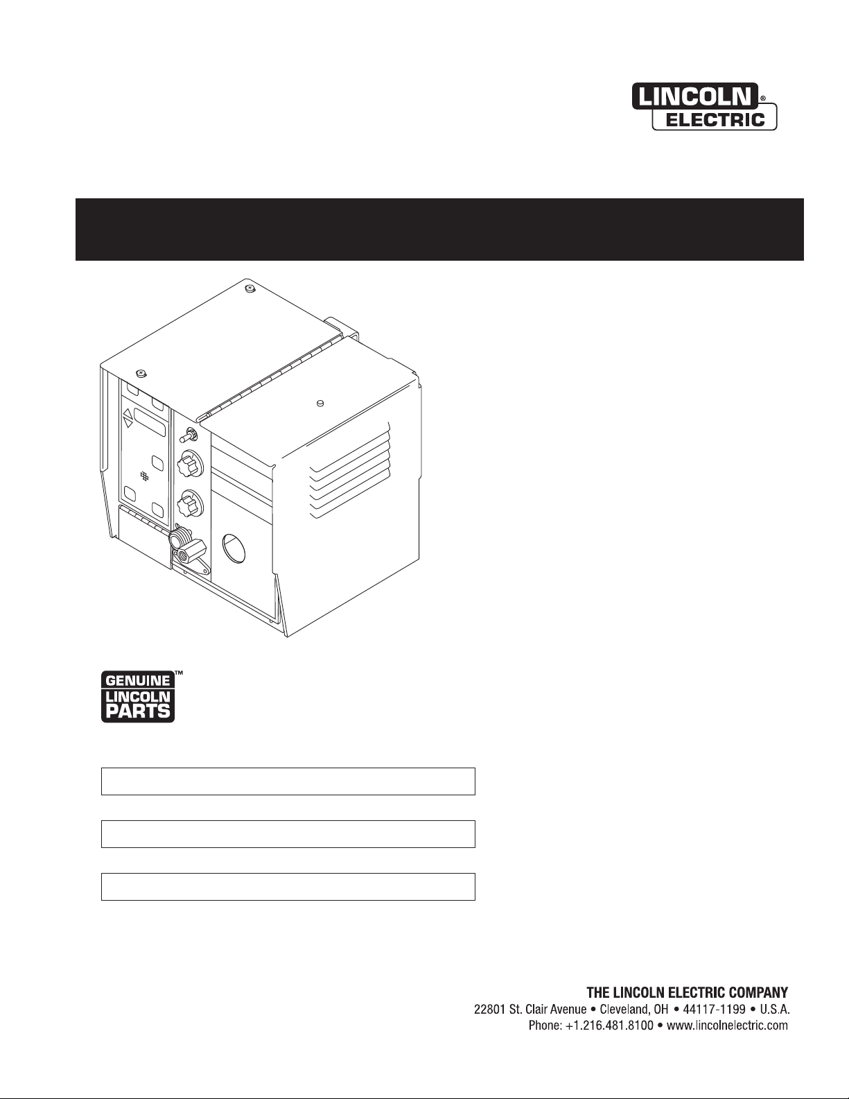
Synergic 7 and 7H
For use with machines having Code Numbers:
10250, 10251
Save for future reference
Date Purchased
Code: (ex: 10859)
Serial: (ex: U1060512345)
IM557 | Issue D ate Sept- 13
© Lincoln Global, Inc. All Rights Reserved.
Register your machine:
www.lincolnelectric.com/register
Authorized Service and Distributor Locator:
www.lincolnelectric.com/locator
Page 2
THANK YOU FOR SELECTING
AT ALL
TIMES.
SPECIAL SITUATIONS
Additional precautionary measures
A QUALITY PRODUCT BY
LINCOLN ELEC TRIC.
PLEASE EXAMINE CARTON AND EQUIPMENT FOR
DAMAGE IMMEDIATELY
When this equipment is shipped, title passes to the purchaser upon
receipt by the carrier. Consequently, Claims for material damaged in
shipment must be made by the purchaser against the transportation
company at the time the shipment is received.
SAFETY DEPENDS ON YOU
Lincoln arc welding and cutting equipment is designed and built with
safety in mind. However, your overall safety can be increased by
proper installation ... and thoughtful operation on your part.
DO NOT INSTALL, OPERATE OR REPAIR THIS EQUIPMENT
WITHOUT READING THIS MANUAL AND THE SAFETY PRECAUTIONS
CONTAINED THROUGHOUT. And, most importantly, think before you
act and be careful.
WARNING
This statement appears where the information must be followed
exactly to avoid serious personal injury or loss of life.
CAUTION
This statement appears where the information must be followed to
avoid minor personal injury or damage to this equipment.
KEEP YOUR HEAD OUT OF THE FUMES.
DON’T get too close to the arc. Use
corrective lenses if necessary to
stay a reasonable distance away
from the arc.
READ and obey the Material Safety
Data Sheet (MSDS) and the warning
label that appears on all containers
of welding materials.
USE ENOUGH VENTILATION or
exhaust at the arc, or both, to keep
the fumes and gases from your breathing zone and the general area.
IN A LARGE ROOM OR OUTDOORS, natural ventilation may be
adequate if you keep your head out of the fumes (See below).
USE NATURAL DRAFTS or fans to keep the fumes away from your
face.
If you de velop unusual symptoms, see your supervisor. Perhaps the
welding atmosphere and ventilation system should be checked.
WEAR CORRECT EYE, EAR & BODY PROTECTION
PROTECT your eyes and face with welding helmet
properly fitted and with proper grade of filter plate
(See ANSI Z49.1).
PROTECT your body from welding spatter and arc
flash with protective clothing including woolen
clothing, flame-proof apron and gloves, leather
leggings, and high boots.
PROTECT others from splatter, flash, and glare with
protective screens or barriers.
IN SOME AREAS, protection from noise may be
appropriate.
BE SURE protective equipment is in good condition.
Also, wear safety glasses in work area
DO NOT WELD OR CUT containers or materials which previously had
been in contact with hazardous substances unless they are properly
cleaned. This is extremely dangerous.
DO NOT WELD OR CUT painted or plated parts unless special
precautions with ventilation have been taken. They can release highly
toxic fumes or gases.
PROTECT compressed gas cylinders from excessive heat, mechanical
shocks, and arcs; fasten cylinders so they cannot fall.
BE SURE cylinders are never grounded or part of an electrical circuit.
REMOVE all potential fire hazards from welding area.
ALWAYS HAVE FIRE FIGHTING EQUIPMENT READY FOR
IMMEDIATE USE AND KNOW HOW TO USE IT.
Page 3
SECTION A:
Diesel Engines
Gasoline Engines
WARNINGS
CALIFORNIA PROPOSITION 65 WARNINGS
Diesel engine exhaust and some of its constituents are known
to the State of California to cause cancer, birth defects, and other
reproductive harm.
The engine exhaust from this product contains chemicals known
to the State of California to cause cancer, birth defects, or other
reproductive harm.
ARC WELDING CAN BE HAZARDOUS. PROTECT
YOURSELF AND OTHERS FROM POSSIBLE SERIOUS
INJURY OR DEATH. KEEP CHILDREN AWAY. PACEMAKER WEARERS SHOULD CONSULT WITH THEIR
DOCTOR BEFORE OPERATING.
Read and understand the following safety highlights. For additional
safety information, it is strongly recommended that you purchase a
copy of “Safety in Welding & Cutting - ANSI Standard Z49.1” from the
American Welding Society, P.O. Box 351040, Miami, Florida 33135 or
CSA Standard W117.2-1974. A Free copy of “Arc Welding Safety”
booklet E205 is available from the Lincoln Electric Company, 22801
St. Clair Avenue, Cleveland, Ohio 44117-1199.
BE SURE THAT ALL INSTALLATION, OPERATION,
MAINTENANCE AND REPAIR PROCEDURES ARE
PERFORMED ONLY BY QUALIFIED INDIVIDUALS.
SAFETY
1.d. Keep all equipment safety guards, covers and
devices in position and in good repair.Keep
hands, hair, clothing and tools away from
V-belts, gears, fans and all other moving parts
when starting, operating or repairing
equipment.
1.e. In some cases it may be necessary to remove safety guards to
perform required maintenance. Remove guards only when
necessary and replace them when the maintenance requiring
their removal is complete. Always use the greatest care when
working near moving parts.
1.f. Do not put your hands near the engine fan. Do not attempt to
override the governor or idler by pushing on the throttle control
rods while the engine is running.
1.g. To prevent accidentally starting gasoline engines while turning
the engine or welding generator during maintenance work,
disconnect the spark plug wires, distributor cap or magneto wire
as appropriate.
1.h. To avoid scalding, do not remove the radiator
pressure cap when the engine is
hot.
ELECTRIC AND
MAGNETIC FIELDS MAY
BE DANGEROUS
2.a. Electric current flowing through any conductor
causes localized Electric and Magnetic Fields (EMF). Welding
current creates EMF fields around welding cables and welding
machines
FOR ENGINE POWERED
EQUIPMENT.
1.a. Turn the engine off before troubleshooting
and maintenance work unless the
maintenance work requires it to be running.
1.b. Operate engines in open, well-ventilated
areas or vent the engine exhaust fumes outdoors.
1.c. Do not add the fuel near an open flame
welding arc or when the engine is running.
Stop the engine and allow it to cool before
refueling to prevent spilled fuel from
vaporizing on contact with hot engine parts
and igniting. Do not spill fuel when filling
tank. If fuel is spilled, wipe it up and do not start engine until
fumes have been eliminated.
2.b. EMF fields may interfere with some pacemakers, and welders
having a pacemaker should consult their physician before
welding.
2.c. Exposure to EMF fields in welding may have other health effects
which are now not known.
2.d. All welders should use the following procedures in order to
minimize exposure to EMF fields from the welding circuit:
2.d.1. Route the electrode and work cables together - Secure
them with tape when possible.
2.d.2. Never coil the electrode lead around your body.
2.d.3. Do not place your body between the electrode and work
cables. If the electrode cable is on your right side, the
work cable should also be on your right side.
2.d.4. Connect the work cable to the workpiece as close as possible to the area being welded.
2.d.5. Do not work next to welding power source.
3
Page 4
SAFETY
ELECTRIC SHOCK
CAN KILL.
3.a. The electrode and work (or ground) circuits are
electrically “hot” when the welder is on. Do
not touch these “hot” parts with your bare skin
or wet clothing. Wear dry, hole-free gloves to insulate hands.
3.b. Insulate yourself from work and ground using dry insulation.
Make certain the insulation is large enough to cover your full area
of physical contact with work and ground.
In addition to the normal safety precautions, if
welding must be performed under electrically
hazardous conditions (in damp locations or while
wearing wet clothing; on metal structures such as
floors, gratings or scaffolds; when in cramped
positions such as sitting, kneeling or lying, if there
is a high risk of unavoidable or accidental contact
with the workpiece or ground) use the following
equipment:
• Semiautomatic DC Constant Voltage (Wire) Welder.
• DC Manual (Stick) Welder.
• AC Welder with Reduced Voltage Control.
3.c. In semiautomatic or automatic wire welding, the electrode,
electrode reel, welding head, nozzle or semiautomatic welding
gun are also electrically “hot”.
3.d. Always be sure the work cable makes a good electrical
connection with the metal being welded. The connection should
be as close as possible to the area being welded.
3.e. Ground the work or metal to be welded to a good electrical (earth)
ground.
3.f. Maintain the electrode holder, work clamp, welding cable and
welding machine in good, safe operating condition. Replace
damaged insulation.
3.g. Never dip the electrode in water for cooling.
3.h. Never simultaneously touch electrically “hot” parts of electrode
holders connected to two welders because voltage
two can be the total of the open circuit voltage of both
welders.
3.i. When working above floor level, use a safety belt to protect
yourself from a fall should you get a shock.
between the
ARC RAYS CAN BURN.
4.a. Use a shield with the proper filter and cover plates to protect your
eyes from sparks and the rays of the arc when welding or
observing open arc welding. Headshield and filter lens should
conform to ANSI Z87. I standards.
4.b. Use suitable clothing made from durable flame-resistant material
to protect your skin and that of your helpers from the arc rays.
4.c. Protect other nearby personnel with suitable, non-flammable
screening and/or warn them not to watch the arc nor expose
themselves to the arc rays or to hot spatter or metal.
FUMES AND GASES
CAN BE DANGEROUS.
5.a. Welding may produce fumes and gases
hazardous to health. Avoid breathing these
fumes and gases. When welding, keep your head out of the fume.
Use enough ventilation and/or exhaust at the arc to keep fumes
and gases away from the breathing zone. When welding
with electrodes which require special ventilation
such as stainless or hard facing (see instructions
on container or MSDS) or on lead or cadmium
plated steel and other metals or coatings which
produce highly toxic fumes, keep exposure as low
as possible and within applicable OSHA PEL and
ACGIH TLV limits using local exhaust or
mechanical ventilation. In confined spaces or in
some circumstances, outdoors, a respirator may
be required. Additional precautions are also
required when welding on galvanized steel.
5. b. The operation of welding fume control equipment is affected by
various factors including proper use and positioning of the
equipment, maintenance of the equipment and the specific
welding procedure and application involved. Worker exposure
level should be checked upon installation and periodically
thereafter to be certain it is within applicable OSHA PEL and
ACGIH TLV limits.
5.c. Do not weld in locations near chlorinated hydrocarbon vapors
coming from degreasing, cleaning or spraying operations. The
heat and rays of the arc can react with solvent vapors to form
phosgene, a highly toxic gas, and other irritating products.
3.j. Also see It ems 6.c. and 8.
5.d. Shielding gases used for arc welding can displace air and
injury or death. Always use enough ventilation, especially in
confined areas, to insure breathing air is safe.
5.e. Read and understand the manufacturer’s instructions for this
equipment and the consumables to be used, including the
material safety data sheet (MSDS) and follow your employer’s
safety practices. MSDS forms are available from your welding
distributor or from the manufacturer.
5.f. Also see item 1.b.
4
cause
Page 5
SAFETY
WELDING AND CUTTING
SPARKS CAN CAUSE
FIRE OR EXPLOSION.
6.a. Remove fire hazards from the welding area. If
this is not possible, cover them to prevent the
welding sparks from starting a fire. Remember that welding
sparks and hot materials from welding can easily go through
small cracks and openings to adjacent areas. Avoid welding near
hydraulic lines. Have a fire extinguisher readily available.
6.b. Where compressed gases are to be used at the job site, special
precautions should be used to prevent hazardous situations.
Refer to “Safety in Welding and Cutting” (ANSI Standard Z49.1)
and the operating information for the equipment being used.
6.c. When not welding, make certain no part of the electrode circuit is
touching the work or ground. Accidental contact can cause
overheating and create a fire hazard.
6.d. Do not heat, cut or weld tanks, drums or containers until the
proper steps have been taken to insure that such procedures will
not cause flammable or toxic vapors from substances inside.
They can cause an explosion even though they have been
“cleaned”. For information, purchase “Recommended Safe
Practices for the Preparation for Welding and Cutting of
Containers and Piping That Have Held Hazardous Substances”,
AWS F4.1 from the American Welding Society (see address
above).
6.e. Vent hollow castings or containers before heating, cutting or
welding. They may explode.
6.f. Sparks and spatter are thrown from the welding arc. Wear oil free
protective garments such as leather gloves, heavy shirt, cuffless
trousers, high shoes and a cap over your hair. Wear ear plugs
when welding out of position or in confined places. Always wear
safety glasses with side shields when in a welding area.
6.g. Connect the work cable to the work as close to the welding area
as practical. Work cables connected to the building framework or
other locations away from the welding area increase the
possibility of the welding current passing through lifting chains,
crane cables or other alternate circuits. This can create fire
hazards or overheat lifting chains or cables until they fail.
6.h. Also see item 1.c.
CYLINDER MAY EXPLODE IF
DAMAGED.
7.a. Use only compressed gas cylinders containing
the correct shielding gas for the process used
and properly operating regulators designed for
the gas and pressure used. All hoses, fittings,
etc. should be suitable for the application and
maintained in good condition.
7.b. Always keep cylinders in an upright position securely chained to
an undercarriage or fixed support.
7.c. Cylinders should be located:
• Away from areas where they may be struck or subjected
to physical damage.
• A safe distance from arc welding or cutting operations
and any other source of heat, sparks, or flame.
7.d. Never allow the electrode, electrode holder or any other
electrically “hot” parts to touch a cylinder.
7.e. Keep your head and face away from the cylinder valve outlet
when opening the cylinder valve.
7.f. Valve protection caps should always be in place and hand tight
except when the cylinder is in use or connected for use.
7.g. Read and follow the instructions on compressed gas cylinders,
associated equipment, and CGA publication P-l, “Precautions for
Safe Handling of Compressed Gases in
Cylinders,” available
from the Compressed Gas Association 1235 Jefferson Davis
Highway, Arlington, VA 22202.
FOR ELECTRICALLY
POWERED EQUIPMENT.
8.a. Turn off input power using the disconnect
switch at the fuse box before working on the
equipment.
8.b. Install equipment in accordance with the U.S. National Electrical
Code, all local codes and the manufacturer’s recommendations.
6.I. Read and follow NFPA 51B “ Standard for Fire Prevention During
Welding, Cutting and Other Hot Work”, available from NFPA, 1
Batterymarch Park, PO box 9101, Quincy, Ma 022690-9101.
6.j. Do not use a welding power source for pipe thawing.
8.c. Ground the equipment in accordance with the U.S. National
Electrical Code and the manufacturer’s recommendations.
Refer to
http://www.lincolnelectric.com/safety
for additional safety information.
Welding Safety
Interactive Web Guide
for mobile devices
5
Page 6

vi
TABLE OF CONTENTS
Page
Installation .......................................................................................................Section A
Technical Specifications ........................................................................................A-1
General Description...............................................................................................A-2
Recommended Processes and Equipment ...........................................................A-2
Standard Features.................................................................................................A-2
Keypad and Display Description............................................................................A-4
Safety Precautions ................................................................................................A-5
Installation of the Synergic 7 Components ............................................................A-5
Attaching Wire Reel Stand ..............................................................................A-5
Wire Feed Drive Roll and Guide Tube Kits............................................................A-6
Standard 4-Roll Kits (KP655 and KS656) .......................................................A-6
Procedure to Install Drive Roll and Guide Tubes...................................................A-6
Gun and Cable Assemblies ...................................................................................A-7
GMAW Guns ...................................................................................................A-7
Innershield Guns .............................................................................................A-7
Gun and Cable Connections..................................................................................A-7
Wire Feeder to Gun.........................................................................................A-7
For GMA Gun Cables......................................................................................A-7
Synergic 7 Water Connections ..............................................................................A-8
GMAW Shielding Gas............................................................................................A-8
Gas Guard Regulator ......................................................................................A-8
Electrical Installation..............................................................................................A-9
Optional Features Installation..............................................................................A-10
vi
Operation ............................................................................................................Section B
Safety Precautions ................................................................................................B-1
Duty Cycle .............................................................................................................B-1
Keypad Setup and Operation ................................................................................B-1
Procedure Selector Switch ....................................................................................B-4
Dual Procedure Remote Control (K1449-1)...........................................................B-4
Wire Reel Loading .................................................................................................B-5
Idle Roll Pressure Setting ......................................................................................B-9
Gas Guard Regulator Setting ................................................................................B-9
Making a Weld.....................................................................................................B-10
Wire Reel Changing.............................................................................................B-10
Wire Feed Overload Protection ...........................................................................B-10
Grounding Lead Protector ...................................................................................B-11
Explanation of Prompting and Error Messages ...................................................B-11
Accessories .....................................................................................................Section C
Optional Features..................................................................................................C-1
Maintenance ....................................................................................................Section D
Safety Precautions ................................................................................................D-1
Routine Maintenance.............................................................................................D-1
Periodic Maintenance............................................................................................D-1
Troubleshooting ..............................................................................................Section E
Safety Precautions.................................................................................................E-1
Troubleshooting Guide ..........................................................................................E-2
Procedure for Replacing PC Boards....................................................................E-12
Diagrams ..........................................................................................................Section F
Wiring.....................................................................................................................F-1
Input Connection....................................................................................................F-2
Dimension Print......................................................................................................F-3
Parts Lists ...................................................................................................P-278 Series
Page 7
A-1
INSTALLATION
TECHNICAL SPECIFICATIONS – SYNERGIC 7 AND 7H
WIRE FEEDER - (4 - ROLL)
Model
SYNERGIC 7 SYNERGIC 7H
A-1
Type
Wire Speed Range:
IPM
M/M
Wire Size Capabilities:
Solid Electrodes
Cored Electrodes
Input Power:
Temperature Rating:
Operating
Storage
The following is for both the Synergic 7 and
Synergic 7H models:
K631-3
50 - 770
1.25 - 19.5
.025 - 1/16”
0.6 - 1.6mm
.045 - 3/32”
1.2 - 2.4mm
K631-4
80 - 1200
2.00 - 30.5
.025 - .045”
0.6 - 1.2mm
.045”
1.2mm
40-42 V ± 10%
50/60 Hz
4.0 Amps
-20°C to +40°C
-40°C to +40°C
NRTL/C
Size & Weight Without Wire Stand With K377 Wire Stand
4-Roll Feeder:
Length
Width
Height
Total Weight
(Less Electrode)
SYNERGIC 7 & 7H
269 mm (10.60")
295mm (11.60”)
282mm (11.11”)
12.9 kg (28.5 lbs.)
550 mm (21.66")
295mm (11.60”)
432mm (17.00”)
17.5 kg (38.5 lbs.)
Page 8

A-2
INSTALLATION
GENERAL DESCRIPTION
The Synergic 7 is a semiautomatic constant speed wire
feeder designed specifically for use with the Invertec Power
Wave type power sources. A serial communication link is
supplied through the control cable of the Synergic 7
enabling information to be shared between the power
source and wire feeder. The Synergic 7 comes factory
equipped with a gas solenoid valve with gas fittings and
standard Lincoln gun connector. These models includes a
3-1/2 digit LED display with rotating knob encoder controls
for setting the wire feed speed and voltage and a dual procedure selector switch. A tactile-feel keypad provides
selection of operating mode, function selection, timer and
crater fill selection and parameter adjustment. Two keys
provide Cold Feed and Gas Purge functions, and connector
receptacles are provided for an optional dual procedure
remote control and dual procedure switch.
The unit has 3 operating modes: 2-step trigger, 4-step trigger and spot. Three functions can be selected: Volts or
Trim Preset/arc (memory) voltmeter, Run-in speed and weld
speed (IPM or m/min.) or (memory) ammeter. In addition,
when 4-step trigger mode is selected, crater fill WFS is also
adjustable. Up to three timers are available depending on
the mode: preflow, postflow and spot, and 5 acceleration
rates are selectable, as well as 6 Burnback settings.
A-2
b) Feeds .045 - (1.2mm) cored wire for Outershield
GMA or Innershield processes.
Recommended power sources are The Lincoln
Electric Company Synergic type Invertec® Power
Wave power sources with 42VAC auxiliary power, and
a 14-pin connector receptacle.
STANDARD FEATURES
Wire Drive Features:
Wire Drive Unit - Incorporates low voltage permanent
magnet motor and highly efficient two-reduction spur
gearbox which operates in any position. The non-fluid
lubricant wonʼt leak.
“Quick Release” Wire Feed System - Provides a
completely tool-less means for releasing and opening
the idle roll pressure arm, precisely adjusting the idle
roll pressure and changing the incoming and outgoing
guide tubes and drive rolls.
Drive Rolls and Guide Tubes - Provide long life,
positive feeding and precise alignment of electrode.
Minimizes “birdnest” or mill-thru of wire if properly set.
(Ordered separately.)
The Synergic 7 is available in 2 models:
Ordering Speed Range Wire Size Range
Information Model Drive IPM (m/m) IN. (MM)
K631-3 Synergic 4-Roll 50 - 770 .025 - 3/32
7 (1.25 - 19.5) (0.6 - 2.4)
K631-4 Synergic 4-Roll 80 - 1200 .025 - .045
7H (2.00 - 30.5) (0.6 - 1.2)
RECOMMENDED PROCESSES
AND EQUIPMENT
The Synergic 7 wire feed unit has the following wire
feeding capabilities:
a) Feeds .025 - 1/16” (0.6-1.6mm) solid wire for
gas-metal-arc processes.
b) Feeds .045 - 3/32” (1.2-2.4mm) cored wire for Outershield
GMA or Innershield processes up to 5/64” (2.0 mm).
The Synergic 7H wire feed unit has the following wire
feeding capabilities:
Tachometer Feedback - Provides proper wire feed
acceleration and speed accuracy, independent of fluctuations in line voltage and wire loading, for reliable
arc starting and weld consistency.
Run-in Speed Setting - Allows the arc striking speed
“Run-in” to be adjusted independently of the weld feed
speed for starting optimization.
Cold Feed Speed - Provides cold feed speed adjustment
independent of weld, run-in and crater speeds.
Selectable Acceleration - Provides front panel selection of 5 acceleration rates. This feature in combination with Run-in Speed provides the ability to easily
optimize starting on any process or procedure.
Solid-State Dynamic Braking -
motor to minimize wire overrun during weld termination. Solid-state design requires no maintenance.
Quickly stops wire feed
a) Feeds .025 - .045” (0.6-1.2mm) solid wire for
gas-metal-arc processes.
SYNERGIC 7 & 7H
Page 9

A-3
Crater Fill - Provides crater feed speed adjustment (in
4-step trigger mode) independent of weld, cold inch,
or run-in speeds.
Solid-State Overload Protection - No circuit breaker
to reset. Front panel display indicates time remaining
before automatic reset.
Gas Solenoid Valve - Complete with inlet fittings for
easy installation of gas is standard on Synergic 7
models. Also available as an option (K659-1) a Gas
Guard regulator for flow surge suppression.
English/Metric Speed Display - Provides front panel
selection of speed display in units of IPM or M/M.
INSTALLATION
A-3
2-Step or 4-Step Trigger Modes - Unit operates only
when trigger is pressed in 2-Step mode (normal) operation. 4-Step Trigger Mode eliminates the need to
hold the gun trigger closed while welding. Both models have user selectable 4-step with crater fill, or as
shipped, 4-step with current interlock.
Gas Preflow and Postflow Timers - Allows setting of
shielding gas preflow time (0-2.5 seconds) before
welding arc starts, and gas postflow time
(0-9.9 seconds), after welding arc stops.
Crater Fill - Allows setting of crater fill WFS (when 4step with crater fill trigger mode is selected), independent of weld, cold feed, and run-in speeds.
4-Roll Drive - Both models employ 4-Roll Drive, with
2 driven rolls, providing optimal feeding force for problem feeding situations, with low wire deformation for
improved feeding of soft wires.
Control Features:
Microcomputer Based Control - Provides precise
setting and display of all parameters and precision
timing functions. Optimizes wire drive control for crisp
acceleration and smooth response with precise
repeatability. Allows synergic control of various welding processes by communicating information over a
serial link to the compatible power source.
Display and Indicator Lights - Wide temperature
range, long life, 3-1/2 digit 7-segment LED display
with .56” (14.2mm) character height permits easy
viewing even from long gun cable distances.
Individual red indicator lights are high intensity LEDʼs
for viewing at almost any angle. Mode and Timer function keys and indicator lights are concealed behind a
hinged “drop-door” cover.
Encoder Controls - Rotating encoders provide continuous knob control for setting both Wire Feed Speed
and Volts/Trim procedures.
Procedure Switch - Permits selection of A or B procedures, as set by the procedure controls and memory pair selected at the Power Wave power source.
Setting switch to center “Gun Switch” position allows
selection of A or B procedures with the optional Dual
Procedure Switch.
Keypad - Consists of 7 membrane keys with tactilefeel embossed domes. All keys are generously
spaced to provide easy selection, even if wearing
welding gloves.
Selectable Burnback Time - Provides front panel
selection of 6 Burnback times. This feature provides
selectable Burnback time (default = 0ms) if required to
prevent electrode from sticking in weld puddle at finish
of weld.
Spot Mode - Allows a single timed weld cycle each
time the gun trigger is held closed. Duration (0.2-9.9
seconds) is set by the Spot ON timer.
Digital “Memory” Voltmeter - Displays arc voltage
from 0 to 80V DC, when welding gun trigger is activated, with automatic polarity indication for positive or
negative electrode. The last welding voltage monitored at end of weld is displayed for 5 seconds after
weld has stopped. This allows checking actual voltage after weld has stopped.
Digital “Memory” Ammeter - Weld Feed Speed
(WFS) display may be selectable to display welding
amps only while welding and the last welding amps
monitored at the end of the weld will be displayed for
5 seconds after the weld has stopped. This allows
checking actual weld current after the weld has
stopped.
Power-down Save - All settings, including mode,
Run-in speed, cold feed speed, crater speed, weld
speed, timers, English-Metric units and acceleration
are automatically saved when power is removed. This
feature does not require batteries and when power is
restored it will automatically return all settings to the
state they were in when power was removed.
However, the power source may overwrite any or all
of these parameters after Power-Up Recall is complete.
SYNERGIC 7 & 7H
Page 10
A-4
INSTALLATION
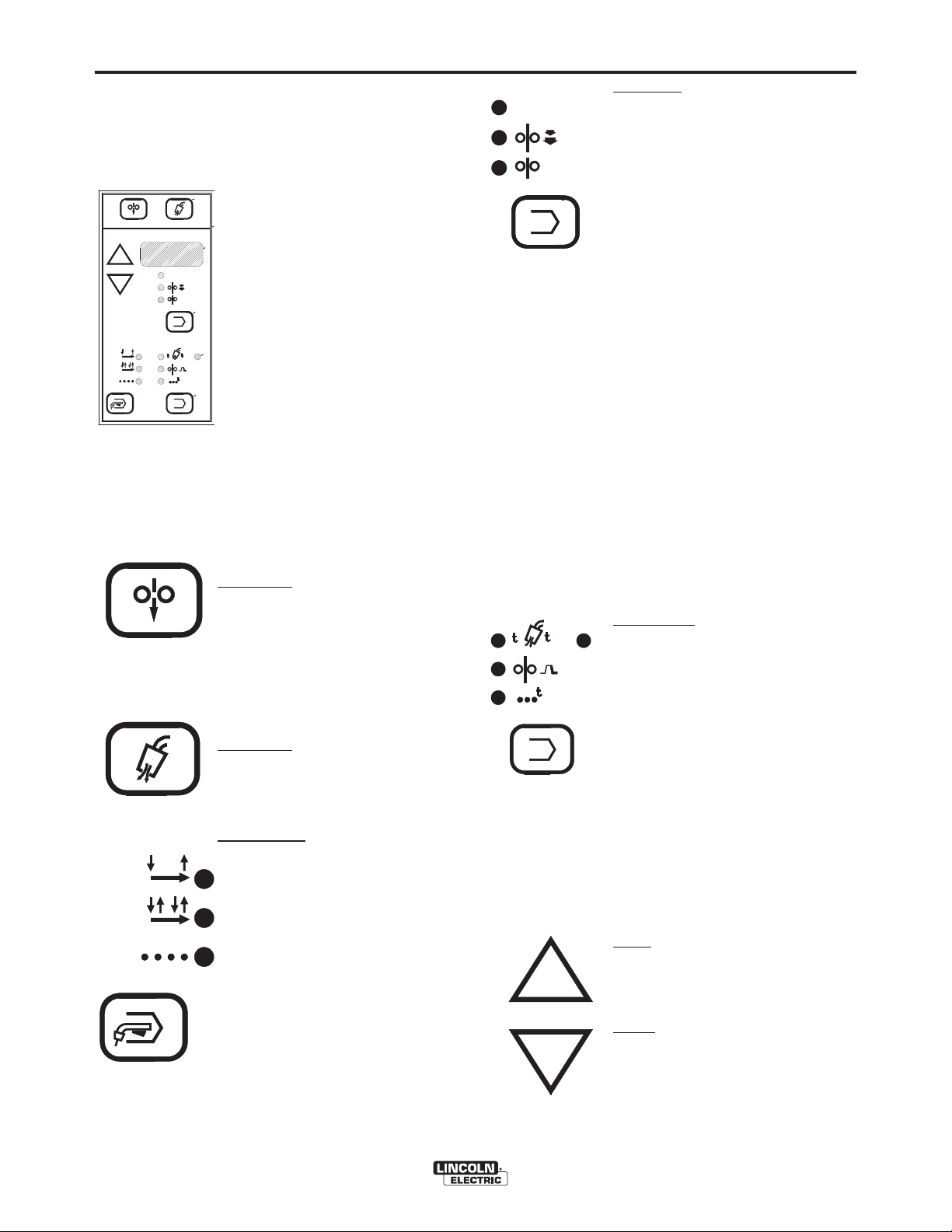
KEYPAD AND DISPLAY
DESCRIPTION
Keypad - Seven key, membrane
L9571-1
type with “snap” tactile feel and
COL D FEED GAS PURGE
V
2- STEP
4- STEP
LOCK
SPOT
PREFL OW
STD
1
COLD FEED
embossed domes. Long life
design. Spatter resistant surface.
TRIM/VOLTS
Display - 3-1/2 digit 7-segment
RUN- I N
LED with (+) or (-) polarity indica-
WFS
tors. .56” (14.2mm) character
height. Displays arc voltage in
POSTF LOW
volts, wire speed in IPM or m/m and
2
all timers in seconds.
CRATER
SPOT
Indicator Lights - Extra bright red
LEDʼs for viewing at almost any
angle. Always indicates the mode
being used and which function or
timer is being displayed.
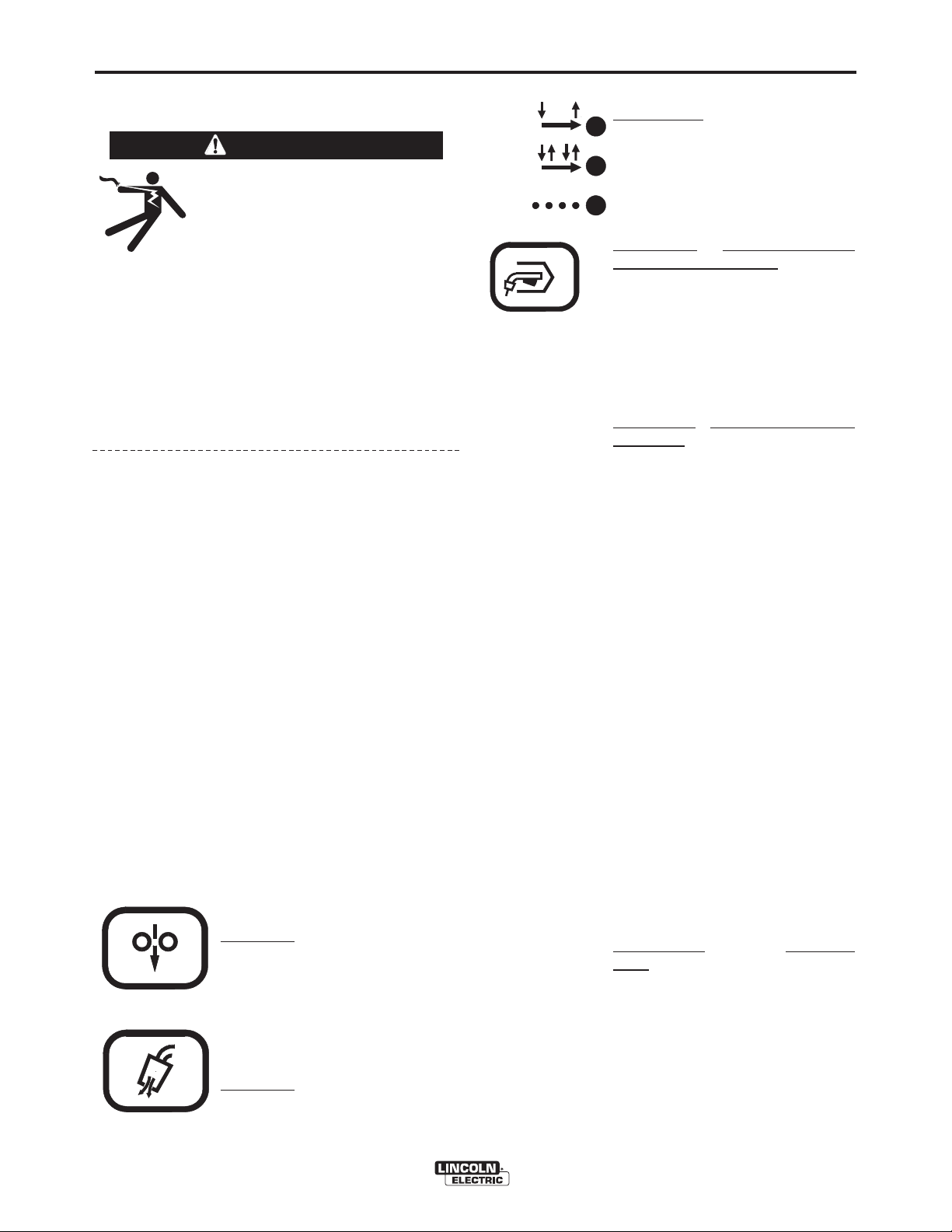
Cold Feed key energizes the wire
feeder but not the power source or
solenoid valve. Cold feed speed is
adjustable and is displayed only
while pressing Cold Feed, and the
last speed selected is stored in
memory for the next Cold feeding.
1
V
VO LTS
WFS
2
A-4
Function Select key enables operator to choose which
function will be displayed as shown by the appropriate
TRIM
/
indicator light. Pressing the key causes lights to sequence
RUN- I N
(top to bottom) starting from the current indicated position.
The function displayed will be adjustable with the rotating
encoder controls or arrow keys:
Adjusting either encoder knob automatically transfers display (and indicator light) to the function being adjusted.
Top Light - Indicates display of preset voltage or percent
trim when not welding and arc voltage while welding (as
indicated by top light “blinking”), and continues for 5 seconds after the weld has stopped (memory vpltmeter). The
power source automatically determines whether preset
voltage or percent trim will be displayed, and adjustable
with Volts/Trim rotating encoder control.
Middle Light - Indicates Run-in speed is being displayed.
As shipped, these models are setup for a 50 IPM
(1.27m/min) fixed run-in speed with display function deactivated. They may be user-selected to activate or deactivate adjustable Run-in display, and setting with arrow
keys.
Bottom Light - Indicates Weld Feed Speed (WFS) is being
displayed, and is adjustable with the Wire Feed Speed
rotating encoder control. If selected, this light will “blink”
while welding, indicating that the display has been selected to display welding amps, and continues for 5 seconds
after the weld is stopped (memory ammeter).
Timer/Crater Select
or gas timers, or crater speed as indicated by the appropriate light. Pressing the key causes lights to sequence
CRATER
(left to right, top to bottom) starting from the current indicated selection. Any parameter not available in the mode
SPOT
selected is skipped over.
key enables operator to choose spot
GAS PURGE
2- STEP
STD
4- STEP
LOCK
SPOT
Gas Purge
key energizes the solenoid valve but not the wire feeder or
power source.
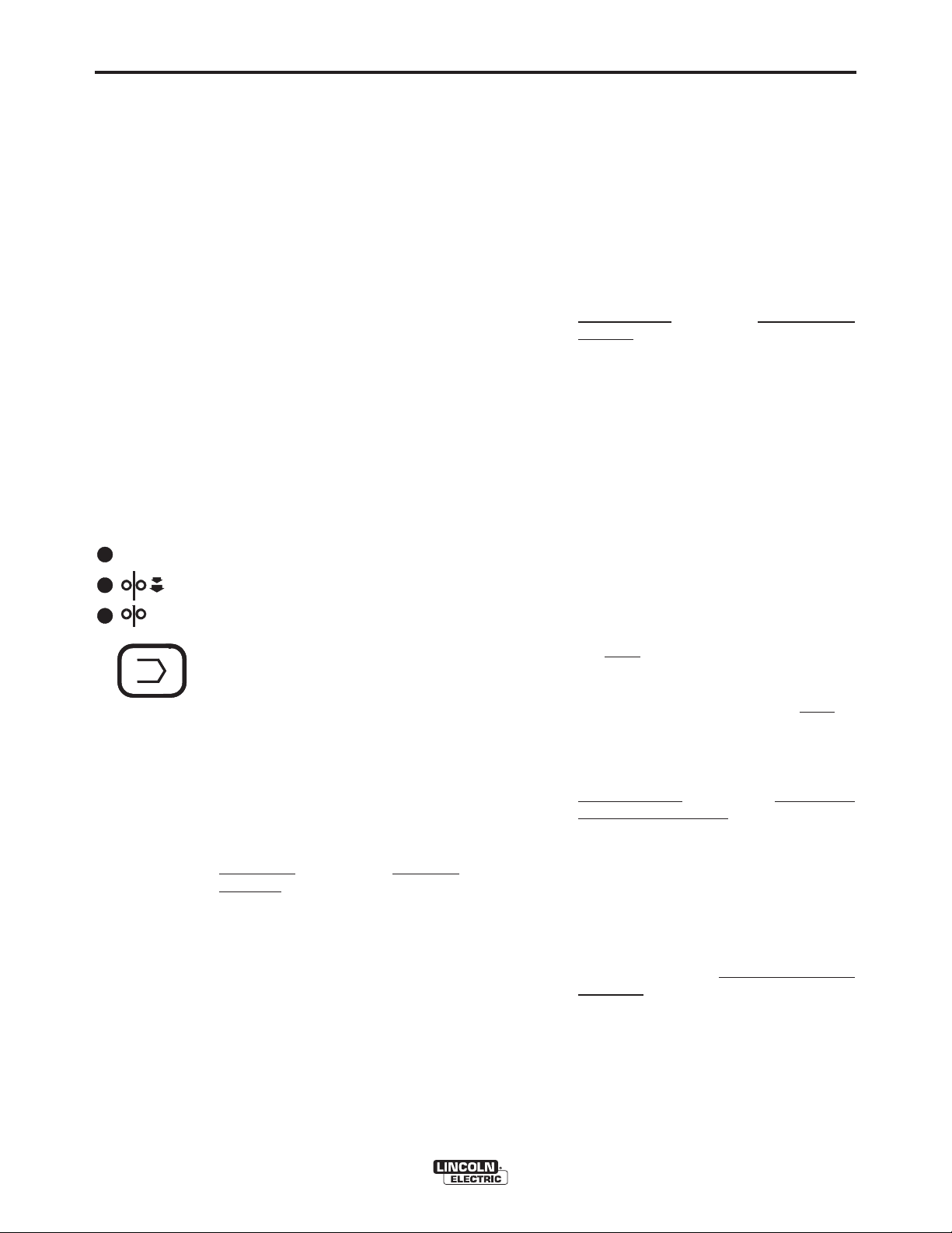
Mode Select
key enables operator
to choose mode of operation shown
by the indicator lights. Pressing key
causes mode lights to sequence
(top to bottom) starting from the
current indicated selection.
Top Light - Indicates 2-step (standard) trigger mode.
Middle Light - Indicates 4-step
(lock) trigger mode. This mode may
be selected to include crater fill or
weld current interlock.
Bottom Light - Indicates spot weld
mode.
SYNERGIC 7 & 7H
Top Left Light - indicates preflow time is being displayed in
seconds.
Top Right Light - indicates postflow time is being displayed in seconds.
Middle Light - indicates Crater Feed Speed is being displayed. This display will only occur if 4-step mode with
crater fill is selected.
Bottom Light - indicates spot on time is being displayed in
seconds.
Increase arrow key increases the setting of the parameter selected to be displayed. Arrow keys do not
function for Wire Feed Speed or Volts/Trim settings,
which are adjusted using the rotating encoder knobs.
Decrease
arrow key decreases the setting of the parameter selected to be displayed. Arrow keys do not
function for Wire Feed Speed or Volts/Trim settings,
which are adjusted using the rotating encoder knobs.
Page 11

A-5
INSTALLATION
INSTALLATION OF THE SYNERGIC 7 COMPONENTS
Safety Precautions
WARNING
ELECTRIC SHOCK can kill.
• Do not touch electrically live parts such
as output terminals or internal wiring.
•
When inching with gun trigger, electrode and
drive mechanism are “hot” to work and
ground and could remain energized several
seconds after the gun trigger is released.
• Turn OFF input power at welding power
source before installation or changing
drive roll and/or guide tubes.
• Welding power source must be connected
to system ground per the National
Electrical Code or any applicable local
codes.
• Only qualified personnel should
perform this installation.
Observe all additional Safety Guidelines detailed
throughout this manual.
A-5
Attaching Wire Reel Stand
The mounting hardware for mounting the wire reel
stand is included with the wire feeder. (Screws and
washers are inserted in their respective mounting
holes.) To connect:
1) Remove the three 3/8" (9.5 mm) hex head screws
from the back of the wire feed unit.
2) Place the wire reel stand mounting bracket in position against the back of the wire feed unit.
3) Replace and tighten the screws. The long screw
and plain washer go into the top hole.
SYNERGIC 7 & 7H
Page 12

A-6
INSTALLATION
Wire Feed Drive Roll and Guide Tube Kits
NOTE: The maximum sizes the Synergic 7 will feed
satisfactorily are the 3/32” (2.4mm) cored and
1/16” (1.6mm) solid electrodes. The maximum
sizes the Synergic 7H will feed satisfactorily are
the .045 (1.2mm) cored and .045” (1.2mm) solid
electrodes.
The electrode sizes that can be fed with each
roll and guide tube are stencilled on each part.
Check the kit for proper components.
Steel Wire Sizes:
* .068 - 3/32” (1.7 - 2.4mm) Cored KP655-3/32
* 1/16” (1.6mm) Cored or Solid KP655-1/16
.045 - .052” (1.2 - 1.4mm) Solid KP655-052S
.045 - .052” (1.2 - 1.4mm) Cored KP655-052C
.035” (0.9-1.0mm) Cored KP655-035C
.035” (0.9-1.0mm) Solid KP655-035S
.030” (0.8mm) Solid KP655-030S
.023” (0.6mm) Solid KP655-025S
4-Roll
A-6
PROCEDURE TO INSTALL DRIVE
ROLL AND GUIDE TUBES
WARNING
ELECTRIC SHOCK can kill.
• Do not touch electrically live parts such
as output terminals or internal wiring.
•
When inching with gun trigger, electrode and
drive mechanism are “hot” to work and
ground and could remain energized several
seconds after the gun trigger is released.
• Turn OFF input power at welding power
source before installation or changing
drive roll and/or guide tubes.
• Welding power source must be connected
to system ground per the National
Electrical Code or any applicable local
codes.
• Only qualified personnel should
perform this installation.
Observe all additional Safety Guidelines detailed
throughout this manual.
Aluminum Wire Sizes:
1/16” (1.6mm) KP656-1/16A
KP647-1/16A**
3/64” (1.2mm) KP656-3/64A
KP647-3/64A**
.040” (1.0mm) KP647-040A**
.035” (0.9mm) KP656-035A
Drive rolls for only cored
electrode sizes are stencilled
with a “C” suffix to the wire sizes.
Drive rolls for only solid
electrode sizes are stencilled
with an “S” suffix to the wire sizes.
Drive rolls for aluminum wire sizes are stencilled with an
“A” suffix to the wire sizes.
* Not for Synergic 7H model.
** For use with Binzel European guns. Installation
instructions are included with these kits. Also
requires K489-2 Fast-Mate Adapter.
Standard 4-Roll Kits (KP655 and KP656)
1) Turn OFF welding power source.
2) Release both quick release levers by sliding the
levers sideways into the open positions.
3) Remove clamping screw & clamping collar from the
drive shaft closest to the incoming side of the feeder.
4) Install drive roll onto keyed shaft. (Do not exceed
the maximum wire size rating of the wire drive.)
Replace collar and tighten clamping screw.
5) Back out the set screw for the middle guide tube.
Install the middle guide tube and slide it up against
the drive roll. DO NOT TIGHTEN THE MIDDLE
GUIDE AT THIS TIME.
6) Install the outgoing drive roll following the same
procedure as steps 3 & 4.
7) Center the middle guide between the two drive rolls
and tighten in place.
SYNERGIC 7 & 7H
Page 13

A-7
INSTALLATION
A-7
8) Back out the screws for the incoming and outgoing
guide tubes.
9) Install the longer guide tube in the rear hole near
the incoming drive roll. Slide the tube in until it
almost touches the roll. Tighten in place.
10) Install the remaining guide tube in the front hole.
Be certain that the proper plastic insert is used.
Fine wire chisel point tube must have largest
radius next to drive roll. Tighten in place.
11) Re-latch both quick release levers.
12) To start new electrode, straighten the first 6"
(150mm) and cut off the first 1" (25 mm). Insert
free end through the incoming tube. Press gun
trigger and push wire into the drive roll.
TO SET IDLE ROLL PRESSURE, see Idle Roll
Pressure Setting.
Gun and Cable Assemblies
GMAW Guns
Gun Cable Connection: Wire Feeder to Gun
Lay the cable out straight. Insert the connector on the
welding conductor cable through the large hole in the
front panel of the Synergic 7 and into the brass conductor block on the front of the gearbox. Make sure it
is all the way in and tighten the hand wheel. Keep this
connection clean and bright. Connect the control
cable polarized plug into the mating 5 cavity receptacle on the front of the control section below the keypad.
For GMA Gun Cables:
Install the barbed fitting and union nut to the 5/8-18
female inert gas fitting on the front of the Synergic 7
wire drive. Connect the 3/16" I.D. gas hose from the
gun cable to the barbed fitting. When the gun is to be
removed, this fitting can be easily detached by loosening the union nut.
An expanding line of Magnum gun and cable assemblies are available to allow welding with solid and
cored electrodes using the GMAW process. See the
appropriate Magnum literature for descriptions of the
200 to 550 ampere air cooled gun and cables that are
available. Gun cable lengths range from 10 ft. (3.0 m)
to 25 ft. (7.6 m) and feed electrode sizes .025" (0.6
mm) to 5/64" (2.0 mm). The entire line of Magnum
Fast-Mate gun and cable assemblies can also be
used by installing a K489-1 Fast-Mate adapter kit.
Innershield Guns
K126 and K115 gun and cable assemblies are
available to allow welding with Innershield electrodes. Gun cable lengths range from 10 ft. (3.0
m) to 15 ft. (4.5 m). The 350 ampere K126 with
Synergic 7 will feed electrode sizes .062" (1.6 mm)
to 5/64" (2.0 mm). The 450 ampere K115 with
Synergic 7 will feed 5/64" (2.0 mm) electrode.
Three smoke extraction gun and cable assemblies
are available, 250 ampere K309, 350 ampere K206
and the 500 ampere K289. All gun cable lengths
are 15 ft. (4.5 m). Both the K206 and K309 with
Synergic 7 will feed electrode sizes .062" (1.6 mm)
to 5/64" (2.0 mm). K289 with Synergic 7 will feed
5/64" (2.0 mm) electrode. These guns require the
use of the K184 vacuum unit for use with Synergic
7.
SYNERGIC 7 & 7H
Page 14

A-8
INSTALLATION
A-8
Synergic 7 Water Connections (for WaterCooled Guns)
These Synergic 7 models must have a K590-4 Water
Connection Kit installed. See Options Installation section.
1) Using male quick-connect fittings (included with
appropriate Synergic 7 input cable assemblies), connect the water hoses to the coolant inlet and outlet on
the back of the Synergic 7. Connect the other ends of
these hoses to the appropriate ports on the water
cooling units.
2) In the event the water line fittings on your water
cooled gun are incompatible with the female quick
connects on the front of the Synergic 7, male quickconnects are provided for installation on 3/16 (5 mm)
I.D. hose (Customer to provide appropriate clamps).
The feeder connectors self seal when disconnected.
GMAW Shielding Gas
WARNING
CYLINDER may explode if damaged.
• Keep cylinder upright and chained to
support.
• Keep cylinder away from areas where
it may be damaged.
• Never lift welder with cylinder attached.
• Never allow welding electrode to touch cylinder.
• Keep cylinder away from welding or other live electrical circuits.
BUILDUP OF SHIELDING GAS may
harm health or kill.
• Shut off shielding gas supply when not
in use.
SEE AMERICAN NATIONAL STANDARD Z-49.1,
“SAFETY IN WELDING AND CUTTING” PUBLISHED
BY THE AMERICAN WELDING SOCIETY.
------------------------------------------------------------------------
Customer must provide a cylinder of shielding gas, a
pressure regulator, a flow control valve, and a hose
from the flow valve to the gas inlet fitting of the
Synergic 7 Wire Feed Unit.
Connect a supply hose from the gas cylinder flow
valve outlet to the 5/8-18 female inert gas fitting on the
back panel of the Synergic 7 or, if used, on the inlet of
the Gas Guard regulator. (See Below).
Gas Guard Regulator - The Gas Guard Regulator is
an optional accessory (K659-1) on these models.
Install the 5/8-18 male outlet of the regulator to the
5/8-18 female gas inlet on the back panel of the
Synergic 7. Secure fitting with flow adjuster key at top.
Attach gas supply to 5/8-18 female inlet of regulator
per instructions in the “Gas Connections” Section.
SYNERGIC 7 & 7H
Page 15
A-9
ELECTRICAL INSTALLATION
WARNING
ELECTRIC SHOCK can kill.
• Do not touch electrically live parts such
as output terminals or internal wiring.
•
When inching with gun trigger, electrode and
drive mechanism are “hot” to work and
ground and could remain energized several
seconds after the gun trigger is released.
• Turn OFF input power at welding power
source before installation or changing
drive roll and/or guide tubes.
• Welding power source must be connected
to system ground per the National
Electrical Code or any applicable local
codes.
• Only qualified personnel should
perform this installation.
Observe all additional Safety Guidelines detailed throughout this manual.
Input Cable: Synergic 7 Wire Feeder to Power
Wave Synergic Type Power Sources
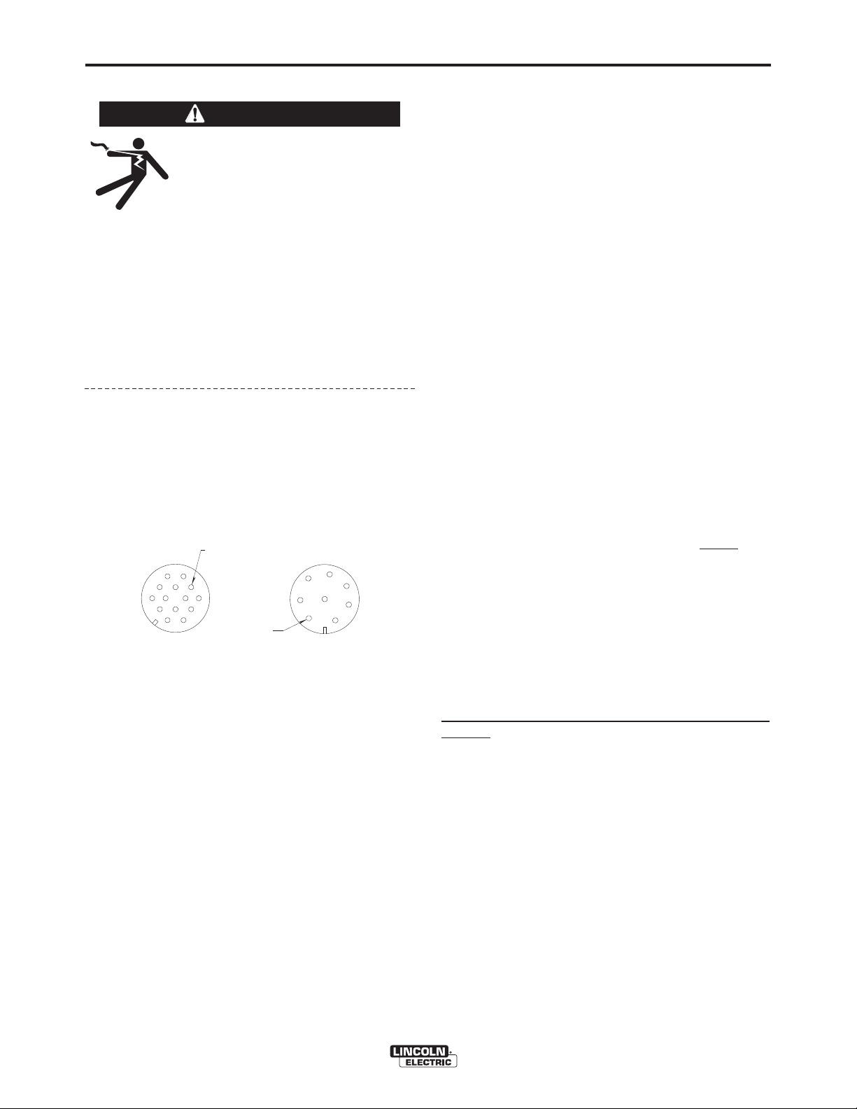
NOTE: CSAnrtl certification of the Synergic 7 models is with
input cable assemblies identified by carton date codes
010161, or above. These assemblies have grounding lead
continuity between the 14-pin plug pin B and the 8-socket
plug pin E per diagram below.
B=GND
E=GND
14-PIN PLUG, FRONT VIEW
K649 - (Used with Power Wave 450/500) Consists of an 8-conductor control cable with a 14-pin control cable plug and a 4/0
(107mm2) electrode cable with Twist-Mate™ connector. It is
rated at 500 amps, 60% duty cycle and is available in lengths of
7 ft (2 m), 17 ft (5 m), 25 ft (7.6 m), 33 ft (10 m) and 50 ft (15 m).
K675 - (Used with Power Wave 450/500) Similar to K649
but includes a gas hose with a 5/8-18 male fitting for the
Synergic 7 inlet. It is rated at 500 amps, 60% duty cycle
and is available in lengths of 7 ft. ( 2 m), 25 ft. (7.6 m) and
50 ft. (15 m).
K641- (Used with Power Wave 450/500 and Synergic 7/7H
with water quick connection) Similar to K649 but includes a
gas hose with a 5/8-18 male fitting for the Synergic 7 inlet
and water hoses with quick-connect male fittings to connect
between the water cooler and the Synergic 7 water connections. It is rated at 500 amps, 60% duty cycle and is available in lengths of 7 ft. (2 m), 17 ft. (5 m), 25 ft. (7.6 m), 33 ft.
(10 m) and 50 ft. (15 m).
K648 - (Used with Power Wave 450) Consists of an 8-conductor control cable with a 14-pin plug and a 4/0 (107 mm
electrode cable with stud terminal. It is rated at 500 amps,
60% duty cycle and is available in lengths of 7 ft (2 m), 17 ft
(5 m), 25 ft (7.6 m), 33 ft (10 m) and 50 ft (15 m).
8-PIN PLUG, FRONT VIEW
INSTALLATION
K676 - (Used with Power Wave 450) Similar to K648 but
includes a gas hose with a 5/8-18 male fitting for the
Synergic 7 inlet. It is rated at 500 amps, 60% duty cycle
and is available in lengths of 7 ft. (2 m), 25 ft. (7.6 m) and 50
ft. (15 m).
K640 - (Used with Power Wave 450 and Synergic 7/7H with
water quick-connection) Similar to K648 but includes a gas
hose with a 5/8-18 male fitting for the Synergic 7 inlet and
water hoses with quick-connect male fittings to connect
between the water cooler and Synergic 7 water connections.
It is rated at 500 amps, 60% duty cycle and is available in
lengths of 7 ft. (2 m), 25 ft. (7.6 m) and 50 ft. (15 m).
K651 - (Used with Power Wave 350) Consists of an 8-conductor control cable with a 14-pin plug and 2/0 (67 mm2)
electrode cable with Twist-Mate™ connector. It is rated at
350 amps, 60% duty cycle and is available in lengths of 7 ft.
(2 m), 17 ft. (5 m), 33 ft. (10 m), and 50 ft. (15 m).
K677-7 - (Used with Power Wave 350) Similar to K651 but
includes a gas hose with a 5/8-18 male fitting for the
Synergic 7 inlet. It is rated at 350 amps, 60% duty cycle
and is available in 7 ft. (2 m) length.
K650 - (Used with Power Wave 350 and Synergic 7/7H with
water quick connection) Similar to K651 but includes a gas
hose with a 5/8-18 male fitting for the Synergic 7 inlet and
water hoses with quick-connect male fittings to connect
between the water cooler and the Synergic 7 water connections. It is rated at 350 amps, 60% duty cycle and is available in lengths of 7 ft. (2 m), 17 ft. (5 m), 33 ft. (10 m) and
50 ft. (15 m).
K642 (Control Cable Only) - Consists of an 8 conductor
control cable with a 14-pin control cable plug, without
trode cable, and is available in lengths of 7 ft (2 m), 17 ft (5
m), 25 ft (7.6 m), 33 ft (10 m) and 50 ft (15 m).
K643 (Control Cable Extension) - Consists of an 8 conductor control cable with 14-pin connectors on each end for
extending the control cable between the power source and
the control cables. Available in lengths of 17 ft (5 m), 25 ft
(8 m), 33 ft (10 m) and 50 ft (15 m).
With input power disconnected from the power
source, install the input cable per connection diagram
S21041 in the rear of this manual and follow exactly
the instructions on the diagram or perform the following:
1) Connect the end of the control cable with the 14pin cable plug to the mating receptacle on the
power source.
2) Connect the electrode lead of that same cable end
to the power source output terminal of the desired
polarity.
3) Route the other end of the electrode cable through
2
)
the large oval hole in the rear panel of the Synergic
7 case. Connect to the brass block on the side of
the gearbox using the bolt provided.
A-9
elec-
SYNERGIC 7 & 7H
Page 16

A-10
4) Connect the remaining end of the control cable
with the 8-socket cable plug to the mating receptacle on the Synergic 7.
5) Install the input cable under the wire reel mounting
stand strain relief clamp. Remove the screws holding the clamp to the base of the wire reel mounting
assembly, put the input cable assembly under the
clamp and reinstall the screws.
Work Cable
Connect a work lead of sufficient size and length (per
the following table) between the proper output terminal
on the power source and the work. Be sure the connection to the work makes tight metal-to-metal electrical contact.
Current
60% Duty
Cycle
300 Amps
400 Amps
Copper Work Cable Size, AWG *
Up to 100 ft Length (30m)
00 (67 mm2)
000 (85 mm
INSTALLATION
2
)
A-10
K163 Undercarriage (Requires K303, K376, K377, or
K378) The undercarriage includes casters, wheels, a
handle and related hardware. Casters are mounted at
the front and the wheels to the rear of the platform.
The handle is bolted to the front of the platform so the
Synergic 7 can be tilted back and wheeled like a twowheel truck. Instruction sheet M13424 for assembly
installing the K303, K376, K377, or K378 wire stand is
provided with the undercarriage.
K683-1 - Dual Procedure Switch Dual Procedure
Switch mounts to gun with appropriate bracket, provided, per the installation instructions included with the
kit. 3-pin switch cord plug connects to 3-pin remote
receptacle on the front panel of the Synergic 7 Wire
Feed Unit.
K1449-1 - Dual Procedure Remote Control Provides
remote rotating knob encoder control of Wire Feed
Speed and Volts/Trim, along with a dual procedure
selector switch, which disables comparable front panel
controls when the remote control is connected.
2
500 Amps
* For pulse welding applications, the next larger cable
size is recommended.
000 (85 mm
)
OPTIONAL FEATURES
INSTALLATION
K178-1 Mounting Platform - Synergic 7 Models on
Synergic Power Sources (Requires a K303, K376,
K377, K378 or K445 Wire Reel Assembly) This is a
turntable type platform for mounting the Synergic 7 on
the top of Synergic power sources. Bolt the platform to
the lift bail per instructions (M16260) supplied with the
platform.
K162-H Spindle for Mounting Readi-Reels and 2" (51
mm) I.D. Spools (60 lb/27 kg Capacity) (For use with
K303 and K376 Wire Reel Stand) To mount the 2" spindle kit for Readi-Reels and 10 through 60 pound
spools, remove the shaft for the standard 50-60 pound
wire coils from the mounting framework. Install the
spindle per the instructions shipped with the kit.
When used with Readi-Reels, a Readi-Reel Adapter is
required.
For 8" O.D. (200 mm) spools, a K468 Spindle Adapter
is available.
The 4-pin plug of the remote control connects to the
mating receptacle on the bottom of the Synergic 7
Control box.
K590-4 - Water Connection Kit Install per the instructions shipped with the kit.
K648, K649, K651 or K642 Input Cable Assembly
See Electrical Installation section for instructions
K675, K676 or K677 Input Cable Assembly (Gas)
See Electrical Installation and Shielding Gas
Connections sections for instructions.
K640, K641 or K650 Input Cable Assembly (Water &
Gas) See Electrical Installation, Water Connections
and Shielding gas connections sections for instructions.
K376 50-60 Lb. Wire Reel Mounting Stand (without
dust shield) and
K303 50-60 Lb. Wire Reel Mounting Stand (with dust
shield) The assembly includes a framework to which is
attached the 50-60 lb. wire reel, a mounting spindle, a
lift bail, and a cable clamp for fastening the input cable
assembly. It is easily mounted to the basic wire feed
unit by three bolts. The reel mounting spindle is the
pull knob type with a built-in brake.
The brake pad is adjustable for proper braking at low
or high wire feed speeds.
SYNERGIC 7 & 7H
Page 17

A-11
INSTALLATION
A-11
Wire Reel Dust Shield for K376 50-60 Lb. Wire Reel
Mounting Stand - If the user desires to protect the
wire from falling dirt and dust, there is a shield available to cover the wire reel. Order part number
S14543. Instructions are included with the kit.
Wire Reel Dust Shield Door for K303 and K376
(when equipped with an S14543 shield) - In
extremely dusty and dirty locations, this door kit can
be added to those units having the shield kit
(S14543). This door kit includes a hinged door and
sliding bottom seal. When these parts are attached to
the reel support per the instructions included, the unit
becomes a completely enclosed housing. Order part
number M11514.
K377 - Small Mounting Stand for Readi-Reel Coils or
10-44 Pound (4.5-20 kg) Spools with 2" I.D. - This
assembly includes a small frame to which is attached
a wire reel spindle similar to the K162 Spindle. The
unit is supplied with the K363 Readi-Reel Adapter for
using the Lincoln "Readi-Reel Electrode Coils".
Without the adapter, the unit is capable of handling
spools with a 2" (51mm) I.D., a 12" (30mm) maximum
O.D., and a 4" (101mm) width. For spools with an 8"
(200mm) O.D., a K468 spindle adapter is available.
The spindle has an adjustable braking system. See
Installation section “Attaching the Wire Reel Stand”
for mounting to wire feed unit.
K1524-1 Universal Wire Reel Stand - The assembly
includes a reel stand, a 2" (51 mm) O.D. spindle with
adjustable brake, rubber mounting feet, and a cable
clamp for fastening the input cable. It is easily mounted to the wire feed unit by three bolts. The wire feeder reel stand assembly fits on top of the power source
and is correctly positioned by using a hole in the base
that accommodates the power source lift bale. The 2"
(51mm) O.D. spindle can be set on one of two mounting locations on the stand, depending on what coil of
wire and spindle adapter is being used. The upper
hole mounts 50-60 lb coils, the lower hole mounts 1030 lb, 13-14 lb, and 8" O.D. coils. Installation instructions are included with the kit.
K1555-1 Insulated Lift Bale Kit for K1524-1 - A lift
bale can be added to the K1524-1 Universal Wire
Reel Stand. The K1555-1 provides electrical insulation between the wire stand assembly and the lift
hook. It is easily mounted to the wire stand with three
bolts and a threaded plate. Installation instructions are
included with the kit.
K1556-1 Caster Kit for K1524-1 - A light duty caster
kit can be added to the K1524-1 Universal Wire Reel
Stand. The K1556-1 includes 4 2" O.D. light duty
casters that mount in place of the rubber feet on the
wire stand base. Installation instructions are included
with the kit.
K378 - Small Mounting Stand for 13-14 Pound
Innershield Coils - This assembly includes the same
smaller frame as used in the K377 and a fully
enclosed canister system for de reeling of the 14
pound (6 kg) coil. This system has a fixed brake for
this coil. See Installation section “Attaching the Wire
Reel Stand” for mounting to wire feed unit.
K659-1 - Gas Guard Regulator - Adjustable flow regulator with removable adjustor key for CO2 and Argon
blend gases. Mounts onto feeder inlet, and reduces
gas waste and arc start "blow" by reducing surge
caused by excess pressure in supply hose.
Install the 5/8-18 male outlet of the regulator to the
5/8-18 female gas inlet on the back panel of the
Synergic 7. Secure fitting with flow adjuster key at
top. Attach gas supply to 5/8-18 female inlet of regulator per See Installation section “Shielding Gas
Connections”.
K1557-1 Swivel Platform for K1524-1 - A swivel platform can be added to the K1524-1 Universal Wire
Reel Stand. The K1557-1 includes a pivot top plate
and a base assembly. The pivot top plate mounts to
the underside of the base of the wire stand assembly
using four screws. The swivel base mounts to the
power source lift bale with hardware provided or it can
be mounted to a surface of choice with four customer
provided bolts. Installation instructions are provided
with the kit.
SYNERGIC 7 & 7H
Page 18
B-1
OPERATION
B-1
OPERATING INSTRUCTIONS
Safety Precautions
WARNING
ELECTRIC SHOCK can kill.
• Do not touch electrically live parts such
as output terminals or internal wiring.
•
When inching with gun trigger, electrode and
drive mechanism are “hot” to work and
ground and could remain energized several
seconds after the gun trigger is released.
• Turn OFF input power at welding power
source before installation or changing
drive roll and/or guide tubes.
• Welding power source must be connected
to system ground per the National
Electrical Code or any applicable local
codes.
• Only qualified personnel should
perform this installation.
Observe all additional Safety Guidelines detailed
throughout this manual.
Duty Cycle
The Synergic 7 models are rated at 60% duty cycle *
a maximum current of 600 amps.
* Based on a 10 minute time period (6 minutes on, and 4 minutes off).
KEYPAD SETUP AND OPERATION
Power-Down Save
Power to the Synergic 7 is supplied and controlled
from the power source. The Synergic 7 automatically
senses the loss of power when the power source is
turned off.
Procedure settings, including mode, crater speed,
cold feed speed , run-in speed, weld speed, timers
and acceleration are automatically saved when power
is removed. Arc Voltage setting is retained by the
synergic power source. This feature does not require
batteries and when power is restored it will automatically return all settings to the state they were in when
power was removed. The power source may automatically overwrite any or all of these settings following power-up recall.
Operation Keys
COLD FEED
GAS PURGE
Cold Feed
feeder but not the power source or
solenoid valve. This cold feed
speed is digitally displayed and is
adjustable (with “Arrow keys”) only
while pressing the Cold Feed Key.
The last setting is held in memory
for next Cold feeding.
Gas Purge
noid valve but not the wire feeder or
power source.
key energizes the wire
key energizes the sole-
for
SYNERGIC 7 & 7H
2- STEP
STD
4- STEP
LOCK
SPOT
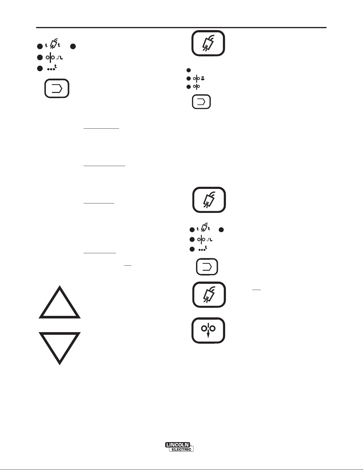
Mode Selection
Mode Select
key ( behind “dropdoor” cover) enables operator to
choose mode of operation shown
by the indicator lights. Pressing key
causes mode lights to sequence
(top to bottom) starting from the
current indicated position.
Top Light
- Indicates 2-Step
(Standard) Trigger Mode.
1. Trigger closure energizes the
solenoid valve, then the wire feeder
and the power source after Preflow
time (See Timer/ Crater Section).
2. Releasing the trigger turns off the
wire feeder and power source and
then the solenoid valve after
Postflow time.
Middle Light - Indicates 4-Step (Lock)
Trigger Mode. These models have selectable
4-step with crater fill or, as shipped, 4-step
with current interlock. (See 4-step trigger
mode selection for method of switching).
The 4-step modes function as follows:
1. Trigger closure energizes the power
source and wire feeder after the preflow time.
2. Trigger release enables 4-step lock,
leaving the feeder and power source
as in step 1.
a) 4-step with current interlock will only
lock if weld current is flowing.
Breaking weld arc stops wire feed
and power source output.
b) 4-step with crater fill will lock without
welding.
3. Closing the trigger a second time
continues welding.
a) 4-step with current interlock contin-
ues welding without changing the
settings from step 2.
b) 4-step with crater fill continues weld-
ing but changes to the crater settings.
4. Releasing the trigger turns off wire
feeder and power source and then
gas solenoid after postflow time.
Bottom Light - Indicates Spot Weld
Mode. Trigger closure energizes the
solenoid valve, then wire feeder and
the power source. The spot on timer
starts when current flows. The wire
feeder and power source then solenoid valve are all turned off when the
spot on timer times out even through
the trigger is still closed.
Page 19
B-2
V
VO LTS
WFS
OPERATION
Display Control Keys
The function select, timer/crater
select, arrow keys and rotational
encoders all effect the display.
Pressing the function select key will
cause a function to be displayed.
Pressing the timer/crater select key
will cause a timer or crater feed
speed to be displayed. Whichever
is pressed last is the one that will
be displayed since they cannot be
displayed simultaneously. Only
one function or timer indicator light
can be on at one time and therefore
it always indicates what is being
displayed. The arrow keys allow
you to adjust the Run-in speed
timer or crater speed being displayed. The encoder knobs allow
rotational adjustment of weld wire
feed speed and Arc Volts/Trim.
Note: If an indicator light is skipped, that
parameter may not be enabled. Refer to
section covering that parameter.
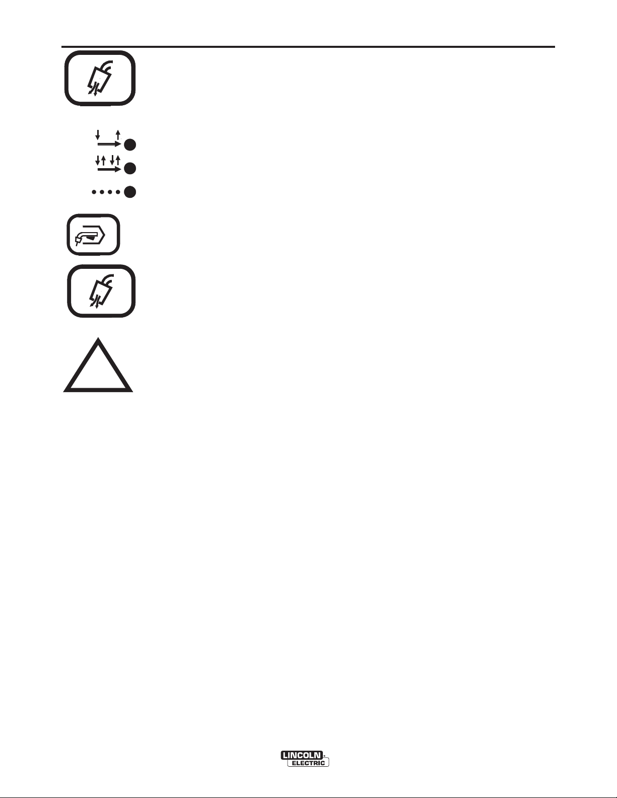
Function Select key enables operator to choose which function will
TRIM
/
be displayed as indicated by the
RUN- I N
appropriate light. Pressing the key
causes lights to sequence (top to
bottom) starting from the current
indicated position. If a timer or
crater speed is being displayed
when the Function Select key is
pressed, then the indicator light of
the last function selected before the
timer/crater key was chosen will
come on and become the starting
point for the sequencing.
Adjusting either encoder knob automatically transfers display (and indicator light)
to the function being adjusted (Volts/Trim
or Wire Feed Speed).
Top Light - indicates Voltmeter
Function has been selected and arc
voltage (in volts) will be displayed along
with electrode polarity when the trigger
has been pressed. When the trigger is
not pressed, this will serve as a preset
voltage/trim function and the preset
voltage/trim will be displayed. The top
light “blinks” when arc voltage is being
displayed and stays lit when preset voltage/trim is displayed. The last welding
voltage displayed before the weld is
stopped, will continue to be displayed
for 5 seconds
operator monitoring.
after welding to permit
B-2
The preset voltage/trim may be adjusted,
using the Volts/Trim encoder knob. The synergic preset voltage/trim level may be adjusted within the range synergically set by the
power source for the process and weld Feed
Speed being used.
matically determines whether preset voltage or percent trim will be displayed.
Preset voltage is indicated by one digit only
to the right of the decimal point, while percent trim always displays two digits to the
right of the decimal point.
Middle Light
Function has been selected and the Run-In
speed setting is being displayed in IPM or
m/m (see section for English or Metric display).
As shipped these models are setup for
minimum rated fixed Run-In speed with display function deactivated. They may be
user-selected to activate or deactivate
adjustable Run-In display. (See section for
selection of Run-In and resetting fixed RunIn speed).
Wire will be fed at the Run-In speed rate
until arc current begins to flow. Once arc
current flows, wire will be fed at the Weld
speed rate. Decreasing Run-In speed
below its lower limit (using the down arrow
key) causes the display to read “- - -”. This
indicates that the Run-In speed will be kept
the same
can reset a different Run-In speed simply
by pressing the up arrow key.
The Run-In speed will also be the same
the weld speed setting if rapid restrike
welding applications are used, where the
arc is restruck in a fraction of a second
after the previous welding arc was stopped.
Bottom Light
Speed (WFS) Function has been selected
and the weld speed setting is being displayed in IPM or m/m (see section for
English or Metric speed display). The
range of Weld Feed Speed is synergically
set by the power source for the process
being used, and is adjustable using the
Wire Feed Speed encoder knob on the
front of the Synergic 7 Control.
If selected (see Memory Ammeter
Selection section), the bottom light will
“blink” while welding, indicating that the display has been selected to display welding
amps. The last welding current displayed
before the weld is stopped will continue to
be displayed for 5 seconds after welding to
permit operator monitoring.
as the weld speed setting. You
The power source auto-
- Indicates Run-In Speed
as
- Indicates Weld Feed
SYNERGIC 7 & 7H
Page 20
B-3
OPERATION
Timer/Crater Select - key enables
operator to choose crater speed, spot
2
1
or gas timers as indicated by the appropriate light. Pressing key causes lights
to sequence (left to right, top to bottom)
CRATER
SPOT
starting from the current indicated position. Any parameter not available in the
mode selected is skipped over. If a
function is being displayed when the
Timer/Crater Select key is pressed,
GAS PURGE
TRIM
VOLTS
/
V
RUN- I N
WFS
then the light of the last parameter
selected before the function was chosen will come on and become the starting point for the sequencing.
Acceleration Selection
Pressing both the “Gas Purge” key and then the function select key at the same time causes the acceleration setting to be displayed. The display will indicate “A-X” where X will be a number from 1 through 5
with 5 being the fastest acceleration. This number
can be adjusted using the arrow keys. To exit this
function, press any other key except the arrow key,
gas purge or function select key.
Burnback Time Selection
If necessary, for higher wire feed speeds, burnback
time maybe selected to prevent the electrode from
sticking in the weld puddle a the end of the weld.
B-3
Pressing both the Gas Purge Key then the function
Top Left Light
is being displayed in seconds. This is
the time the shielding gas flows before
the wire feed and power source are
activated.
- indicates preflow time
select key at the same time, displaying acceleration
setting per above, then pressing the function key a
second time, while holding gas purge pressed, displays the burnback time selection. Default is “b0"
which is zero delay. Selecting “b1" through “b5"
increases delay from 10 m sec to 50 m sec in 10 m
Top Right Light
time is being displayed in seconds.
This is the time the shielding gas flows
- indicates postflow
sec increments. To exit this function press any other
key except the arrow keys, gas purge or function
select key.
after the wire feed and power source
are deactivated.
Middle Light
- indicates that crater feed
speed is being displayed. Crater speed
is only available when 4-step trigger
with crater fill is selected. (See 4-step
trigger mode selection section). It is
activated by Step 3 and deactivated by
Step 4 of the 4-step sequence.
Bottom Light
- indicates spot on time is
being displayed in seconds.
NOTE: if unit is not
in spot mode then
this light will be skipped over in the
selection sequence.
Increase Arrow - key increases the
setting of the parameter selected to be
displayed, except Wire Feed Speed and
Volts/Trim which are controlled by the
encoder knobs.
GAS PURGE
2
1
CRATER
SPOT
GAS PURGE
Selection of English or Metric Speed
Display Units
Pressing both the Gas Purge key and then
timer select key at the same time causes the
speed display units to toggle between IPM
(no decimal point displayed) and m/m (a
decimal point displayed). If the speed display units were IPM, then they will change to
m/m. If the speed display units were m/m,
then they will change to IPM. If the display
is showing the volts/trim or one of the timers
when the keys are pressed, the display will
be changed to weld speed to indicate the
selected speed display units.
Run-In Selection
Pressing both the Gas Purge key then the Cold
Feed key at the same time causes Run-In
function to toggle on or off, as indicated by the
Run-In indicator light turning on or remaining
off in the function select sequence.
Decrease Arrow - key decreases the
setting of the parameter selected to be
displayed, except Wire Feed Speed and
Volts/Trim which are controlled by the
encoder knobs.
Arrow Keys use the “Accelerating
Digit” method for setting changes,
where holding the arrow key causes
setting change rate to accelerate from
slow to fast. Releasing arrow key resets
to slow setting change.
SYNERGIC 7 & 7H
COLD FEED
As shipped, the Run-In function is off with a
fixed setting of 50 IPM (1.27 m/min.).
Therefore, the Run-In indicator light will not
sequence with the function select key, but the
fixed setting will still be used for actual Run-In
speed.
Activation of adjustable Run-In speed using the
above dual key press will permit Run-In speed
to be adjusted with the arrow keys, (See
Section 3.3.4), and the Run-In indicator light
will return to the function key sequence. Repressing the above dual key again removes
the Run-In light from the function key
sequence, but replaces the fixed Run-In speed
with the adjusted Run-In speed setting, until
readjusted.
Page 21
B-4
OPERATION
B-4
GAS PURGE
2- STEP
STD
4- STEP
LOCK
SPOT
GAS PURGE
4-Step Trigger Mode
Dual Procedure Remote Control (K1449-1)
Selection
Pressing both the Gas Purge key
and then the Trigger mode select
key causes the 4-step mode light to
turn on and will toggle the 4-step
trigger mode between:
4-step with current interlock (as shipped)
Crater light will not turn on.
and
4-step with crater fill.
Crater light will turn on for crater speed set-
ting with arrow keys.
(See Mode Selection and Display
Control Keys sections).
Memory Ammeter Selection
Pressing both the Gas Purge key
then the Up Arrow key at the same
time causes the WFS light to “blink”
for about 3 seconds while display
shows weld amps reading with electrode polarity symbol. This indicates
that while welding, the display will
show welding amps, indicated by
“blinking” WFS indicator light, which
continues for 5 seconds after the
weld is stopped (memory ammeter)
before returning to displaying WFS
(light not “blinking”.)
Pressing both the Gas
Purge and Up Arrow key again,
returns WFS display to wire speed
while welding.
When this option is connected to the feeder control
receptacle the front panel knob controls are disabled
and procedure control is transferred to the knob
encoder controls of the remote, which function in the
exact same manner.
NOTE: The dual procedure overlay must be present on the Power Wave power source for the
Procedure Selector switch to function. If this
overlay is not used, only Procedure A will be
selected no matter what position the Procedure
switch is in.
If using the optional K683-1 Dual Procedure Switch to
select A or B along with the remote, both the front
panel and remote Procedure selector switches must
be set to “Gun Switch” (center) position.
Procedure Selector Switch
The toggle switch on the front panel provides selection
of Procedure A or Procedure B, as set with the front
panel knob controls. Rotating the knob encoder
changes only the procedure selected by this switch.
Also, this switch selects the A or B memory pair selected at the Power Wave power source.
NOTE: The dual procedure overlay must be present
on the Power Wave power source for the Procedure
Selector switch to function. If this overlay is not
used, only Procedure A will be selected no matter
what position the Procedure switch is in.
Setting the toggle switch to the center “Gun Switch”
position permits the Procedure A or Procedure B to be
selected by the optional K683-1 Dual Procedure
Switch. The K1449-1 Dual Procedure Remote Control
can be used with this panel Procedure Switch in any
position.
SYNERGIC 7 & 7H
Page 22

B-5
OPERATION
B-5
WIRE LOADING
Loading a 22 to 30 Lb. (10 to 14 kg) Readi-Reel
Package Using the Molded Plastic K363-P
Readi-Reel Adapter:
The Spindle should be located in the LOWER mounting hole
of the K1524-1 Universal Stand if used.
1) Depress the Release Bar on the Retaining Collar and
remove it from the spindle. NOTE: Earlier spindles
used a threaded collar. See Figure B.1a or B.1b.
2) Place the Adapter on the spindle.
3) Re-install the Retaining Collar. Make sure that the
Release Bar “pops up” and that the collar retainers
fully engage the retaining groove on the spindle.
4) Rotate the spindle and adapter so the retaining
spring is at the 12 o'clock position.
5) Position the Readi-Reel so that it will rotate in a
direction when feeding so as to be de-reeled from
the bottom of the coil.
6) Set one of the Readi-Reel inside cage wires on the
slot in the retaining spring tab.
7) Lower the Readi-Reel to depress the retaining
spring and align the other inside cage wires with
the grooves in the molded adapter.
8) Slide the cage all the way onto the adapter until
the retaining spring "pops up" fully.
WARNING
Check to be sure the Retaining Spring has fully
returned to the locking position and has SECURELY
locked the Readi-Reel Cage in place. Retaining
Spring must rest on the cage, not the welding electrode.
___________________________________________
9) To remove Readi-Reel from Adapter, depress
retaining spring tab with thumb while pulling the
Readi-Reel cage from the molded adapter with
both hands. Do not remove adapter from spindle.
FIGURE B.1a (Threaded Locking Collar)
2 IN. O.D. SPINDLE ADAPTER
RETAINING SPRING
BRAKE
HOLDING
PIN
GROOVES
READI-REEL
INSIDE CAGE WIRES THREADED
LOCKING
LLAR
FIGURE B.1b (Retaining Collar)
SYNERGIC 7 & 7H
Page 23

B-6
OPERATION
B-6
TO MOUNT 10 TO 44 lb (4.5 to 20 kg) SPOOLS
(12 in./300 mm DIAMETER) OR 13-14 lb (6 kg)
INNERSHIELD COILS:
The spindle should be located in the lower mounting
hole of the K1524-1 Universal Stand if used.
[For 8 in. (200 mm) spools, a K468 spindle adapter
must first be slipped onto the spindle.]
[For 13 to 14 lb (6 kg) Innershield coils, a K435 Coil
Adapter must be used.]
1. Depress the Release Bar on the Retaining Collar
and remove it from the spindle.
spindles used a threaded collar. See Figure B.5a or
B.5b.
2. Place the spool on the spindle, making certain
the spindle brake pin enters one of the holes in
the backside of the spool. Be certain the wire
comes off the reel in a direction so as to de-reel
from the bottom of the coil.
3. Re-install the Retaining Collar. Make sure that
the Release Bar “pops up” and that the collar
retainers fully engage the retaining groove on the
spindle.
NOTE: Earlier
2. While tightly holding the electrode, cut off the bent
end and straighten the first six inches. Cut off the
first inch. (If the electrode is not properly
straightened, it may not feed or may not go into
the outgoing guide tube, causing a “birdnest”.)
3. Insert the free end through the incoming guide
tube.
4. Press the cold inch key or gun trigger and push
the electrode into the drive roll.
WARNING
ELECTRIC SHOCK
can kill.
• Do not touch electrically live parts
such as output terminals or
internal wiring.
• When inching with the gun
trigger, electrode and drive
mechanism are “hot” to work and
ground and could remain “hot” for
several seconds after the gun
trigger is released.
------------------------------------------------------------------------
5. Inch the electrode through the gun.
ELECTRODE FEEDING AND BRAKE
ADJUSTMENT
1. Turn the Readi-Reel or spool until the free end of
the electrode is accessible.
Adjust the brake tension with the thumbscrew on
6.
the spindle hub until the reel turns freely but with
little or no overrun when wire feeding is stopped.
Do not overtighten.
SYNERGIC 7 & 7H
Page 24

B-7
OPERATION
B-7
WIRE REEL LOADING – 50 AND 60 LB
COILS (K303 OR K376 WIRE REEL STAND)
ADJUSTABLE WIRE REEL BRAKE
The mount for standard 50 and 60 pound electrode
coils includes a two-position brake assembly.
Generally the brake should be at the inner position
(nearest to the wire reel shaft) for wire feed speeds
below 400 in./min (10 m/min). It should be at the outer
position for the faster wire speeds often used when
feeding smaller diameter electrode.
To adjust the brake position, remove the wire reel. Pull
the cotter pin that holds the brake shoe to the arm,
move the shoe and replace the cotter pin. Do not bend
the cotter pin - it is held in place by a friction fit.
TO MOUNT A 50 OR 60 LB COIL:
1. To remove the wire reel from its shaft, grasp the
spring loaded knob and pull out. This straightens
the knob so it seats into the shaft when released.
Remove the reel.
2. Lay the reel flat on the floor. Loosen the spinner
nut and remove the cover plate. See Figure B.2.
CAUTION
Always be sure the free end of the coil is securely held
while the tie wires are being cut and until the wire is
feeding through the drive rolls. Failure to do this will
result in “back lashing” of the coil, which may tangle the
wire. A tangled coil will not feed. It must be untangled
or discarded.
------------------------------------------------------------------------
8. Cut and remove only the tie wire holding the free
end of the coil. Insert the free end into one of the
holes in the cover and secure it by bending it
back. Cut and remove the remaining tie wires.
9.
Replace the reel on the wire feeder. Grasp the
shaft knob, pull it out and swing it across the reel
hub, locking the reel in place.
FIGURE B.2 – LOADING A 50 OR 60 LB COIL.
SPINNER
NUT
COVER
PLATE
3. Place the coil of electrode on the reel so it
unwinds as the reel rotates clockwise. DO NOT
cut the tie wires at this time.
4. Be sure the coil is placed so the spring loaded
arms will not interfere with the later removal of the
coil tie wires.
5. When loading 0.030 to 0.045” electrode, be
certain the coil is placed on the reel so the spring
loaded arms are at the center of the slots in the
cardboard coil liner. This provides the positive
compression of the coil sides needed for troublefree wire feeding.
6. Put the cover plate on the reel so the four arms of
the cover plate straddle and are in line with the
spring loaded arms of the reel.
7. Tighten the cover as much as possible by hand.
DO NOT hammer on the spinner nut arms.
COIL
REEL
SLOTS
CARDBOARD
COIL
LINER
TIE WIRE
SPRING
LOADED
ARM
SYNERGIC 7 & 7H
Page 25

B-8
OPERATION
B-8
WIRE REEL LOADING – 50 AND 60 LB
COILS (K1524-1 UNIVERSAL WIRE REEL
STAND)
TO MOUNT A 50 to 60 lb (22.7 to 27.2 kg) COIL:
(USING K1504-1 COIL REEL) (FOR 50 to 60 lb
READI-REELS A K438 READI-REEL ADAPTER
MUST BE USED.)
The spindle should be located in the UPPER mounting hole.
1. With the K-1504-1 Coil Reel mounted on the 2 in.
(51 mm) spindle (or with reel laying flat on the
floor) loosen the spinner nut and remove the reel
cover. See Figure B.3.
2. Before cutting the tie wires, place the coil of electrode on the reel so it unwinds from the bottom
as the reel rotates.
3. Tighten the spinner nut against the reel cover as
much as possible by hand, using the reel cover
spokes for leverage. DO NOT hammer on the
spinner nut arms.
4. Cut and remove only the tie wire holding the free
end of the coil. Hook the free end around the rim
of the reel cover and wrap it around to secure.
Cut and remove the retaining tie wires.
FIGURE B.3 – K1504-1 COIL REEL.
SPINNER NUT
COVER
PLATE
SLOTS
CARDBOARD
COIL LINER
COIL
TIE WIRE
SPRING
LOADED ARM
REEL
CAUTION
Always be sure the free end of the coil is securely
held while the tie wires are being cut and until the wire
is feeding through the drive rolls. Failure to do this will
result in “backlash” of the coil, which may tangle the
wire. A tangled coil will not feed, so it must either be
untangled or discarded.
____________________________________
5. Be sure the coil is engaged with the spindle
brake pin and the Release Bar and Retaining
Collar “pops up” and that the collar retainers fully
engage the retaining groove on the spindle.
Feeding Electrode
1) Turn the reel until the free end of the electrode is
accessible. While tightly holding the electrode, cut
off the bent end.
2) Straighten the first 6” (150mm) and cut off the first
1” (25mm). Insert the free end through the incoming
guide tube. Press the Cold Inch key or the gun trigger
and push the electrode into the drive roll. Feed the
electrode through the gun. (If the electrode is not
properly straightened, it may not feed or may not go
into the outgoing guide tube causing a “birdnest”.)
WARNING
When feeding with the gun trigger, the electrode and
drive mechanism are always “HOT” to work and
ground and could remain “HOT” several seconds after
the gun trigger is released.
___________________________________________
SYNERGIC 7 & 7H
Page 26

B-9
OPERATION
Idle Roll Pressure Setting
The idle roll pressure is set at the factory, backed out
three turns from full pressure on 4-roll feeders. This is
an approximate setting. For small wire sizes and
aluminum wire up to 9 or 10 turns out may be required
to minimize “birdnesting”. The optimum idle roll pressure varies with type of wire, surface condition, lubrication, and hardness. The optimum idle roll setting
can be determined as follows:
1) Release the incoming idle roll pressure arm, then
press end of gun against a solid object that is electrically isolated from the welder output and press
the gun trigger for several seconds.
2) If the wire “birdnests”, jams, or breaks at the drive
roll, the idle roll pressure is too great. Back the
pressure setting out 1/2 turn, run new wire through
gun, and repeat above steps.
3) If the only result is drive roll slippage, disengage
the gun locking nut, and pull the gun cable forward
about 6” (150mm). There should be a slight waviness in the exposed wire. If there is no waviness,
the pressure is too low. Increase the pressure setting 1/4 turn, reconnect the gun, tighten the locking
nut, and repeat the above steps.
B-9
4) After the outgoing pressure is set, determine how
many turns away from full pressure the setting is.
Set both idle roll tensions to this setting. Engage
both idle rolls before welding. In most applications,
best wire feeding will occur when both idle roll
pressures are set the same.
Gas Guard Regulator Setting
1) With the gas supply shut off, the Gas Guard regulator flow adjusting key should be set to maximum
(full clockwise) which is rated to be 60 SCFH (28
lts/ min).
2) Adjust gas supply flow rate for a level higher than
will be required, then adjust Gas Guard flow
adjusting key counterclockwise to the desired gas
flow rate.
SYNERGIC 7 & 7H
Page 27

B-10
OPERATION
Making a Weld
1) Use only Power Wave model “synergic” power
sources.
2) Properly connect the electrode and work leads for
the correct electrode polarity.
B-10
12) To stop welding, release the gun trigger and then
pull the gun away from the work after the arc
goes out and Postflow time, if used, is over.
13) If necessary to optimize arc starting, adjust wire
speed acceleration, and/or Run-In speed. (See
the appropriate sections for adjusting procedures).
3) Use Mode Selection key to set desired operating
mode. (Refer to Mode Selection section.)
4) Use Function Select and Arrow keys to set desired
Run-in and encoder knob to set Weld Feed Speed.
(Set for each procedure if using a Dual Procedure
function). (See the appropriate sections for adjusting procedures).
5) Adjust the voltage or percent trim, if desired, (for
each procedure if using a Dual Procedure function)
using the encoder knob in “Volts/Trim” function
(refer to Volts/Trim section). The final setting can
be adjusted according to the desired arc voltage
while welding.
6) Use Timer/Crater Select and Arrow keys to set
desired timers, or crater speed if 4-step trigger with
Crater fill has been selected. (Refer to the
Timer/Crater section).
7) Feed the electrode through the gun and cable and
then cut the electrode within approximately
.38” (9.5mm) of the end of the contact tip for solid
wire, and within approximately .75” (19mm) of the
extension guide for cored wire.
8) Connect work cable to metal to be welded. Work
cable must make good electrical contact to the
work. The work must also be grounded as stated
in “Arc Welding Safety Precautions”.
WARNING
When using an Open Arc process,
it is necessary to use correct eye,
head, and body protection
____________________________________
9) If used, be sure shielding gas valve is turned on.
10) Position electrode over joint. End of electrode
may be lightly touching the work.
11) Lower welding helmet, close gun trigger and start
welding. Hold the gun so the contact tip to work
distance gives the correct electrical stickout as
required for the procedure being used.
Wire Reel Changing
At the end of a coil, remove the last of the old electrode coil from the conductor cable by either pulling it
out at the nozzle end of the gun or by using the following procedure:
1) Cut the end of the electrode off at the gun end. Do
not break it off by hand because this puts a slight
bend in the wire making it difficult to pull it back
through the nozzle.
2) Disconnect the gun cable from the gun connector
on the Synergic 7 Wire Feed Unit and lay the gun
and cable out straight.
3) Using pliers to grip the wire, pull it out of the cable
from the connector end.
4) After the electrode has been removed, reconnect
the gun cable to the Synergic 7.
Load a new reel of electrode per the instructions in
the Wire Reel Loading sections.
Wire Feed Overload Protection
The Synergic 7 has solid-state overload protection of
the wire drive motor. If the wire drive motor becomes
overloaded for an extended period of time, the protection circuitry turns off the power source, wire feed and
solenoid and then displays H30. This indicates the
wire drive motor is overloaded and the number indicates the time remaining in seconds before the unit
will automatically reset. The number continues to
decrement every second until it reaches 0. At that
time, the unit resets automatically and the previous
display will return indicating the unit is ready to operate again. Overloads can result from improper tip
size, liner, drive rolls, or guide tubes, obstructions or
bends in the gun cable, feeding wire that is larger than
the rated capacity of the feeder or any other factors
that would impede normal wire feeding. (See section
on Avoiding Wire Feeder Problems.)
SYNERGIC 7 & 7H
Page 28

B-11
OPERATION
B-11
Grounding Lead Protector
The frame of the Synergic 7 wire feeder is grounded
to the frame of the power source by a lead in the control cable. An overload protector prevents welding
current from damaging this lead if the electrode circuit
touches the wire feeder frame while the electrode is
electrically hot.
If such a grounding lead fault occurs, the wire feeder
display will show "GLP", and the trigger circuit will be
disabled. To reset the circuit, release the trigger,
make sure that the electrode is not touching the wire
feeder frame, and then either press any key on the
keypad or close the trigger. When the GLP circuit is
reset, the "GLP" display is removed and the wire feeder is returned to normal operating mode.
Explanation of Prompting and
Error Messages
Display Prompt or Error
HI Indicates arc voltage is above 80V DC.
--- Indicates selected Run-In speed will be the
same as the weld speed. To enter a different
Run-In speed simply press the increase arrow
key with Run-In selected.
HXX Indicates wire feed overload. XX indicates
time remaining in seconds before unit resets
automatically. See sections on Routine
Maintenance, Periodic Maintenance, and
Troubleshooting Guide Problem 24.
EP Indicates problem in EPROM assembly. See
Troubleshooting Guide Problem 24.
uP Indicates problem in microprocessor RAM.
See Troubleshooting Guide Problem 24.
EXX Indicates various system problems. XX will
be a number from 01 to 10. Turn off power to
feeder. Wait 5 seconds. Turn power back on.
If error persists, see Troubleshooting Guide
Problem 24. If error does not reoccur, be
sure to check all wire feed speed, acceleration, and timer settings before you proceed.
Er EEPROM error. Usually occurs at power-up.
Indicates one or more of the recalled settings
is out of acceptable limits. Press any key to
return to normal operation. Be sure to check
all wire feed speed, acceleration, and timer
settings before you proceed.
GLP Indicates that the Grounding Lead Protector
circuit was activated due to excessive current
flow into the wire feeder frame. When the
Grounding Lead Protector circuit is activated
the wire feeder is disabled, i.e. the trigger output to the power source is opened up, the
motor is stopped, and the gas solenoid is
turned off. To resume normal operation,
release the trigger, make sure that the electrode is not touching the wire feeder frame,
and then either press a key on the keypad or
close the trigger. See Problem 24 in the
Troubleshooting Guide.
SYNERGIC 7 & 7H
Page 29

C-1
ACCESSORIES
C-1
OPTIONAL FEATURES
DRIVE ROLL AND GUIDE TUBE KITS:
Steel Wire Sizes: 4-Roll
* .068 - 3/32” (1.7 - 2.4mm) Cored KP655-3/32
* 1/16” (1.6mm) Cored or Solid KP655-1/16
.045 - .052” (1.2 - 1.4mm) Solid KP655-052S
.045 - .052” (1.2 - 1.4mm) Cored KP655-052C
.035” (0.9-1.0mm) Cored KP655-035C
.035” (0.9-1.0mm) Solid KP655-035S
.030” (0.8mm) Solid KP655-030S
.023” (0.6mm) Solid KP655-025S
Aluminum Wire Sizes:
1/16” (1.6mm) KP656-1/16A
KP647-1/16A**
3/64” (1.2mm) KP656-3/64A
KP647-3/64A**
.040” (1.0mm) KP647-040A**
.035” (0.9mm) KP656-035A
Drive rolls for only cored electrode sizes are stencilled
with a “C” suffix to the wire sizes.
Drive rolls for only solid electrode sizes are stencilled
with an “S” suffix to the wire sizes.
Drive rolls for aluminum wire sizes are stencilled with an
“A” suffix to the wire sizes.
17 ft. (5 m), 25 ft. (7.6 m), 33 ft. (10 m) and 50 ft. (15
m).
K648 - (Used with Power Wave 450) Consists of an 8conductor control cable with a 14-pin plug and a 4/0
(107 mm
at 500 amps, 60% duty cycle and is available in lengths
of 7 ft (2 m), 17 ft (5 m), 25 ft (7.6 m), 33 ft (10 m) and
50 ft (15 m).
K676 - (Used with Power Wave 450) Similar to K648
but includes a gas hose with a 5/8-18 male fitting for
the Synergic 7 inlet. It is rated at 500 amps, 60% duty
cycle and is available in lengths of 7 ft. (2 m), 25 ft. (7.6
m) and 50 ft. (15 m).
K640 - (Used with Power Wave 450 and Synergic 7/7H
with water quick-connection) Similar to K648 but
includes a gas hose with a 5/8-18 male fitting for the
Synergic 7 inlet and water hoses with quick-connect
male fittings to connect between the water cooler and
Synergic 7 water connections. It is rated at 500 amps,
60% duty cycle and is available in lengths of 7 ft. (2 m),
25 ft. (7.6 m) and 50 ft. (15 m).
K651 - (Used with Power Wave 350) Consists of an 8conductor control cable with a 14-pin plug and 2/0 (67
mm2) electrode cable with Twist-Mate™ connector. It
is rated at 350 amps, 60% duty cycle and is available in
lengths of 7 ft. (2 m), 17 ft. (5 m), 33 ft. (10 m), and 50
ft. (15 m).
2
) electrode cable with stud terminal. It is rated
* Not for Synergic 7H model.
** For use with Binzel European guns. Installation
instructions are included with these kits.
INPUT CABLE ASSEMBLIES:
K649 - (Used with Power Wave 450/500) Consists of an
8-conductor control cable with a 14-pin control cable plug
and a 4/0 (107mm2) electrode cable with Twist-Mate™
connector. It is rated at 500 amps, 60% duty cycle and is
available in lengths of 7 ft (2 m), 17 ft (5 m), 25 ft (7.6 m),
33 ft (10 m) and 50 ft (15 m).
K675 - (Used with Power Wave 450/500) Similar to K649
but includes a gas hose with a 5/8-18 male fitting for the
Synergic 7 inlet. It is rated at 500 amps, 60% duty cycle
and is available in lengths of 7 ft. ( 2 m), 25 ft. (7.6 m)
and 50 ft. (15 m).
K641- (Used with Power Wave 450/500 and Synergic
7/7H with water quick connection) Similar to K649 but
includes a gas hose with a 5/8-18 male fitting for the
Synergic 7 inlet and water hoses with quick-connect male
fittings to connect between the water cooler and the
Synergic 7 water connections. It is rated at 500 amps,
60% duty cycle and is available in lengths of 7 ft. (2 m),
K677-7 - (Used with Power Wave 350) Similar to K651
but includes a gas hose with a 5/8-18 male fitting for
the Synergic 7 inlet. It is rated at 350 amps, 60% duty
cycle and is available in 7 ft. (2 m) length.
K650 - (Used with Power Wave 350 and Synergic 7/7H
with water quick connection) Similar to K651 but
includes a gas hose with a 5/8-18 male fitting for the
Synergic 7 inlet and water hoses with quick-connect
male fittings to connect between the water cooler and
the Synergic 7 water connections. It is rated at 350
amps, 60% duty cycle and is available in lengths of 7 ft.
(2 m), 17 ft. (5 m), 33 ft. (10 m) and 50 ft. (15 m).
K642 (Control Cable Only) - Consists of an 8 conductor control cable with a 14-pin control cable plug, without electrode cable, and is available in lengths of 7 ft (2
m), 17 ft (5 m), 25 ft (7.6 m), 33 ft (10 m) and 50 ft (15
m).
K643 (Control Cable Extension) - Consists of an 8
conductor control cable with 14-pin connectors on
each end for extending the control cable between the
power source and the control cables. Available in
lengths of 17 ft (5 m), 25 ft (8 m), 33 ft (10 m) and 50 ft
(15 m).
SYNERGIC 7 & 7H
Page 30

C-2
ACCESSORIES
C-2
UNIVERSAL WIRE REEL STAND (K1524-1)
Includes a 2" (51mm) O.D. Spindle with adjustable
brake and two locations for mounting the spindle to
allow for the mounting of 50 - 60lb, 10 - 30 lb, 13 14lb, and 8" O.D. coils with proper spindle adapters.
(See OPERATION section) Capable of being mounted on the top of a suitable power source or surface
without the need for any other mounting kit. Optional
features available for this stand include:
• K1555-1 insulated lift bale
• K1556-1 caster kit
• K1557-1 swivel platform.
60 LB. (27.2 KG) COIL ADAPTER (K1504-1)
Permits 50-60 lb. (22.7-27.2 Kg) coils to be mounted
to a 2" (51mm) spindle.
K1551-1 INSULATED LIFT BALE: Provides a
bolt on lift bale with an electrically insulated lift hook.
K1556-1 CASTER KIT: Comes with 4 light duty
2" O.D. casters which mount in place of the rubber
feet on the wire stand. Use in light duty applications
where portability is required. Can be used in combination with the K1557-1 swivel platform.
K1557-1 SWIVEL PLATFORM: Allows for the
mounting of the wire feeder reel stand assembly on
top of a suitable power source if the need for the wire
feeder reel stand assembly to swivel is desired. Also
has mounting holes in the base feet for mounting to
any surface that it can be fastened to. Comes with a
rotating tool tray to hold gun tips, guide tubes, drive
rolls, etc. Will work in combination with the K1556-1
caster kit.
WIRE REEL ASSEMBLY:
K303 - 50-60 lb. (22.7-27.2 kg) Wire reel mounting
stand. Assembly includes a framework to which is
attached the 50-60 lb. (22.7-27.2 kg) wire reel, a
mounting spindle, a dust shield, a lift bail, and a cable
clamp for fastening the input cable assembly. The
reel mounting spindle is the pull knob type with a builtin brake. The brake pad is adjustable for proper braking at low or high wire feed speeds. In extremely
dusty and dirty locations a wire reel dust shield door
kit can be added to this unit.
This door kit, which includes a hinged door and sliding
bottom seal, makes the housing completely enclosed.
Order part number M11514.
K376 - Same as K303 above but without dust shield.
A dust shield that covers the wire reel and protects the
wire from falling dirt and dust is available for this unit.
Order part number S14543. This unit will also accept
the M11514 door kit (see K303 above) but only if
already equipped with optional dust shield (S14543).
K377 - Small mounting stand for Readi-Reel coils or
10-30 lb. (4.5-14 kg) spools with 2" (51 mm) I.D. This
assembly includes a small frame to which is attached
a 2" (51 mm) O.D. wire reel spindle and a K363P
Readi Reel adapter for using the Lincoln "Readi-Reel
Electrode Coils". Without the adapter, the unit is
capable of handling spools with a 2" (51 mm) I.D., a
12" (305 mm) maximum O.D., and a 4" (101 mm)
width.
K378 - Small mounting stand for 13-14 lb. (6 kg)
Innershield coils. This assembly includes the same
smaller frame as used in the K377 and a fully
enclosed canister system for de-reeling of the 14 lb. (6
kg) coil. This system has a fixed brake for this coil.
K445 - 50-60 lb. (22.7-27.2 kg) Readi-Reel mounting
stand. This assembly includes framework to which is
attached a 2" (51 mm) O.D. spindle with adjustable
brake and 50-60 lb. (22.7-27.2 kg) (K438) Readi-Reel
adapter. Includes a lift bail and cable clamp for fastening the input cable assembly. Does not include a
dust shield. A dust shield that covers the wire reel
and protects the wire from falling dirt and dust is available for this unit. Order part number S14543. This
unit will also accept the M11514 door kit (see K303
above) but only if already equipped with optional dust
shield (S14543).
SYNERGIC 7 & 7H
Page 31

C-3
ACCESSORIES
C-3
READI-REEL ADAPTERS:
K363P - Adapts Lincoln Readi-Reel coils of electrode
30 lb (14 kg) and 22 lb (10 kg) to a 2” (51mm) spindle.
Durable molded plastic one piece construction.
Designed for easy loading; adapter remains on spindle for quick changeover. (used with K162H)
K438 - Adapts Lincoln Readi-Reel coils of electrode
50-60 lb (22.7-27.2 kg) to a 2” (51mm) spindle. (used
with K162H).
SPINDLE ADAPTERS:
K162H - Spindle for mounting Readi-Reels and 2”
(51mm) I.D. spools with 60 lb (27.2 kg) capacity. The
shaft for the standard wire coils is removed from the
mounting frame-work and the K162H is installed in its
place. Includes an easily adjustable friction brake for
control of overrun.
When used with Readi-Reels a Readi-Reel adapter is
required.
K435 - Permits 14 lb (6 kg) Innershield coils to be
mounted on 2” (51mm) O.D. spindles. For use with
optional K162H adapter.
K468 - Permits 8” (203mm) O.D. spools to be mounted on 2” (51mm) O.D. spindles. For use with optional
K162H adapter.
K541 Magnum 400 Short Neck GMAW gun and cable
assemblies are rated 400 amps, 60% duty cycle.
(Consult sales specifications for appropriate models)
K598 Magnum 550 GMAW gun and cable assemblies
are rated 550 amps, 60% duty cycle. (Consult sales
specifications for appropriate models)
K206• Innershield Linconditioner gun and cable
assemblies are rated 350 amps, 60% duty cycle.
Maximum size for Synergic 7 models is 5/64" (2.0
mm). Not recommended for Synergic 7H models.
(Consult sales specifications for appropriate models)
K289• Innershield Linconditioner gun and cable
assemblies are rated 500 amps, 60% duty cycle.
Maximum size for Synergic 7 models is 5/64" (2.0
mm). Not recommended for Synergic 7H models.
(Consult sales specifications for appropriate models)
K309• Innershield Linconditioner gun and cable
assemblies are rated 250 amps, 60% duty cycle.
Maximum size for Synergic 7 models is 5/64" (2.0
mm). Not recommended for Synergic 7H models.
(Consult sales specifications for appropriate models)
• K179 type vacuum unit not recommended for use with Synergic 7.
The following Lincoln gun and cable assemblies are
equipped with a Fast-Mate™ connector. They can be
used with these Synergic 7 models by installing a
K489-1 Fast-Mate™ adapter kit.
GUN AND CABLE ASSEMBLIES:
K126 Innershield gun and cable assemblies are rated
at 350 amps, 60% duty cycle. Maximum wire size for
Synergic 7 models is 5/64" (2.0 mm). Not recommended for Synergic 7H models. (Consult sales specifications for appropriate models)
K115 Innershield gun and cable assemblies are rated
at 450 amps, 60% duty cycle. Maximum wire size for
Synergic 7 models is 5/64" (2.0 mm). Not recommended for Synergic 7H models. (Consult sales specifications for appropriate models)
K470 Magnum 300 GMAW gun and cable assemblies
are rated 300 amps, 60% duty cycle. (Consult sales
specifications for appropriate models)
K471 Magnum 400 GMAW gun and cable assemblies
are rated 400 amps, 60% duty cycle. (Consult sales
specifications for appropriate models)
K497 Magnum 200 GMAW gun and cable assemblies
are rated 200 amps, 60% duty cycle. (Consult sales
specifications for appropriate models)
K684 - Magnum “Water Cooled” FM water cooled
GMAW gun and cable assemblies are rated 450
amps, 100% duty cycle (CO
cations for appropriate models).
K498 - Magnum 200 FM GMAW gun and cable
assemblies are rated for 200 amps, 60% duty cycle.
(Consult sales specifications for appropriate models).
K534 - Magnum 250L FM GMAW gun and cable
assemblies are rated for 250 amps, 30% duty cycle.
(Consult sales specifications for appropriate models).
K478 - Magnum 300 FM GMAW gun and cable
assemblies are rated for 300 amps, 60% duty cycle.
(Consult sales specifications for appropriate models).
K479 - Magnum 400 FM GMAW gun and cable
assemblies are rated for 400 amps, 60% duty cycle.
(Consult sales specifications for appropriate models).
K556 * - GMAW process Magnum 400XA X-TRACTOR gun and cable assemblies are rated at 400
amps, 60% duty cycle. (Consult sales specifications
for appropriate models)
2
). (Consult sales specifi-
SYNERGIC 7 & 7H
Page 32

C-4
K566 * - GMAW process Magnum 250XA X-TRAC-
TOR gun and cable assemblies are rated 250 amps,
60% duty cycle. (Consult sales specifications for
appropriate models).
* K179 type vacuum unit not recommended for
use with Synergic 7.
ACCESSORIES
MISC. OPTIONS:
K590-4 (Water Connection Kit) - Includes water sup-
ply quick-connectors already attached to mounting
insulators and internal connection hoses for easy
installation on the front and rear panels of the
Synergic 7 case. Also includes water cooled gun tube
fittings and self-sealing outlet and inlet quick-connectors for mounting to the front of the Synergic 7 case.
K659-1 (Gas Guard Regulator) - Adjustable flow regulator with removable adjustor key for CO2 and Argon
blend gases. Mounts onto wire drive gas inlet, and
reduces gas waste and arc start "blow" by reducing
surge caused by excess pressure in supply hose.
C-4
K1449-1 (Dual Procedure Remote Control) - Includes
a remote control box with a 16ft. (5m) length control
cable with 4-pin plug for the mating receptacle on the
bottom of the Synergic 7 control box. The remote
control box contains 2 rotating knob encoders, one
controls arc voltage and the other controls weld wire
feed speed, and a procedure selector switch which
function the same as comparable controls on the front
panel, which are disabled when the remote is connected.
K683-1 (Dual Procedure Switch) - Kit includes gun
switch, and mountings for Lincoln Innershield and
Magnum guns, with 15 ft. (4.5 m) control cable and 3pin plug.
K163 Undercarriage - For all Synergic 7 wire reel
stand combinations. Includes mounting frame, front
casters, 10" (254 mm) O.D. rear wheels, and handle.
Use when portability is required.
K178-1 Swivel Platform - For all Synergic 7 wire reel
stand combinations. For mounting wire feeder wire
reel stand assembly on top of suitable Lincoln Idealarc
power sources. Recommended input cable length is 7
ft. (2 m) when using the K178-1 on the Invertec power
sources.
SYNERGIC 7 & 7H
Page 33

D-1
MAINTENANCE
Safety Precautions
WARNING
MAINTENANCE
Wire Reel Mounting - 50 (22.7kg) and
60lb (27.2kg) Coils with 1” Spindle
To prolong the life of the reel shaft, periodically coat it
with a thin layer of grease.
D-1
ELECTRIC SHOCK can kill.
• Do not touch electrically live parts such
as output terminals or internal wiring.
•
When inching with gun trigger, electrode and
drive mechanism are “hot” to work and
ground and could remain energized several
seconds after the gun trigger is released.
• Turn OFF input power at welding power
source before installation or changing
drive roll and/or guide tubes.
• Welding power source must be connected
to system ground per the National
Electrical Code or any applicable local
codes.
• Only qualified personnel should
perform this installation.
Observe all additional Safety Guidelines detailed
throughout this manual.
Routine Maintenance
Drive Rolls and Guide Tubes
After feeding every coil of wire, inspect the drive roll
section. Clean it as necessary. Do not use a solvent
for cleaning the idle roll because it may wash the
lubricant out of the bearing. The driver roll and guide
tubes are stamped with the wire sizes they will feed.
If a wire size other than that stamped on the roll(s) is
to be used, the roll(s) and guide tubes must be
changed.
The drive rolls for .035” (0.9mm) through .052”
(1.3mm) cored electrode and 1/16” (1.6mm) through
3/32” (2.4mm) electrode have a double set of teeth so
they can be reversed for additional life. Drive rolls for
.023" (0.6 mm) through .052" (1.3 mm) solid electrodes and aluminum sizes have no teeth, but use two
grooves so they also can be reversed for additional
life.
No maintenance of the two-position adjustable brake
is needed. If the brake shoe wears through to the
metal, replace the brake assembly.
Wire Reel Mounting - Readi-Reels, 10
through 44lb (4.5-20kg) Spools and 5060lb Coils with K1504-1 Adapter
No routine maintenance required. Do not lubricate 2”
(51mm) spindle.
Avoiding Wire Feeding Problems
Wire feeding problems can be avoided by observing
the following gun handling procedures:
a) Do not kink or pull cable around sharp corners.
b) Keep the electrode cable as straight as possible
when welding or loading electrode through cable.
c) Do not allow dolly wheels or trucks to run over
cables.
d) Keep cable clean by following maintenance
instructions.
e) Use only clean, rust-free electrode. The Lincoln
electrodes have proper surface lubrication.
f) Replace contact tip when the arc starts to become
unstable or the contact tip end is fused or
deformed.
g) Do not use excessive wire spindle brake settings.
Periodic Maintenance
Wire Drive Motor and Gearbox
See section on Wire Feed Drive Roll and Guide Tube
Kits for roll changing instructions.
SYNERGIC 7 & 7H
Every year inspect the gearbox and coat the gear
teeth with a moly-disulfide filled grease. Do not use
graphite grease.
Every six months check the motor brushes. Replace
them if they are less than 1/4” long.
Gun and Cable Maintenance
See appropriate Operatorʼs Manual.
Page 34

E-1
TROUBLESHOOTING
WARNING
Service and Repair should only be performed by Lincoln Electric Factory Trained Personnel.
Unauthorized repairs performed on this equipment may result in danger to the technician and
machine operator and will invalidate your factory warranty. For your safety and to avoid Electrical
Shock, please observe all safety notes and precautions detailed throughout this manual.
__________________________________________________________________________
E-1
This Troubleshooting Guide is provided to help you
locate and repair possible machine malfunctions.
Simply follow the three-step procedure listed below.
Step 1. LOCATE PROBLEM (SYMPTOM).
Look under the column labeled “PROBLEM (SYMPTOMS)”. This column describes possible symptoms
that the machine may exhibit. Find the listing that
best describes the symptom that the machine is
exhibiting.
Step 2. POSSIBLE CAUSE.
The second column labeled “POSSIBLE CAUSE” lists
the obvious external possibilities that may contribute
to the machine symptom.
WARNING
ELECTRIC SHOCK can kill.
• Do not touch electrically live parts such
as output terminals or internal wiring.
•
When inching with gun trigger, electrode and
drive mechanism are “hot” to work and
ground and could remain energized several
seconds after the gun trigger is released.
• Turn OFF input power at welding power
source before installation or changing
drive roll and/or guide tubes.
• Welding power source must be connected
to system ground per the National
Electrical Code or any applicable local
codes.
• Only qualified personnel should
perform this installation.
Step 3. RECOMMENDED COURSE OF ACTION
This column provides a course of action for the
Possible Cause, generally it states to contact your
local Lincoln Authorized Field Service Facility.
If you do not understand or are unable to perform the
Recommended Course of Action safely, contact your
local Lincoln Authorized Field Service Facility.
Observe all additional Safety Guidelines detailed
throughout this manual.
CAUTION
If for any reason you do not understand the test procedures or are unable to perform the tests/repairs safely, contact your
Local Lincoln Authorized Field Service Facility for technical troubleshooting assistance before you proceed.
SYNERGIC 7 & 7H
Page 35

E-2
PROBLEMS
(SYMPTOMS)
TROUBLESHOOTING
Observe all Safety Guidelines detailed throughout this manual
POSSIBLE
CAUSE
RECOMMENDED
COURSE OF ACTION
E-2
1. Rough wire feeding or wire not
feeding but drive rolls turning.
a. Gun cable kinked and/or twisted.
b. Wire jammed in gun and cable.
c. Incorrect position of drive rolls with
grooves.
d. Drive rolls loose.
e. Gun cable dirty.
f. Worn drive roll.
g. Electrode rusty and/or dirty.
h. Worn nozzle or cable liner.
i.
Partially flashed or melted contact tip.
a. Inspect gun cable and replace if
necessary.
b. Remove wire from gun and cable
feed in new wire. Note any
obstructions in gun and cable.
Replace gun and cable if necessary.
c. See Wire Feed Drive Roll and
Guide Tubs Kits section for proper
installation of drive roll.
d. Remove, clean, install and tighten.
e. Clean cable or replace liner.
f. Replace.
g. Replace.
h. Replace.
i. Replace contact tip.
2. Variable or “hunting” arc.
j. Incorrect idle roll pressure.
k. Improper liner, tip or guide tube.
a. Wrong size, worn and/or melted
contact tip.
b. Worn work cable or poor work
connection.
c. Loose electrode connections.
d. Wrong polarity.
e. Problem with serial communica-
tions in control cable.
j. Set idle roll pressure per section
on Idle Roll Pressure Setting.
k. Install proper equipment.
a. Replace tip - remove any spatter on end of
tip.
b. Inspect - Repair or replace as necessary.
c. Be sure electrode lead is tight in wire feeder
contact block, gun nozzle and gun tip tight.
d. Check connection at output studs for polari-
ty required by welding process.
e. Make sure control cable connections are
tight. Check for consistent WFS. Make sure
parameters on Power Source display, such
as WFS, match those on wire feeder display,
if not, see Problem 14, otherwise try changing Synergic 7 control board. If problem persists refer to Power Source trouble shooting
information.
CAUTION
If for any reason you do not understand the test procedures or are unable to perform the tests/repairs safely, contact your
Local Lincoln Authorized Field Service Facility for technical troubleshooting assistance before you proceed.
SYNERGIC 7 & 7H
Page 36

E-3
PROBLEMS
(SYMPTOMS)
TROUBLESHOOTING
Observe all Safety Guidelines detailed throughout this manual
POSSIBLE
CAUSE
RECOMMENDED
COURSE OF ACTION
E-3
3. Poor arc striking with sticking or
“blast-offs”, weld porosity, narrow
and ropy looking bead, or electrode stubbing into plate while
welding.
4. Tip seizes in diffuser.
5. Unit shuts off while welding and
“HXX” appears on display.
a. Improper procedures or tech-
niques.
b. Improper gas shielding.
a. Tip overheating due to prolonged
or excessive high current and/or
duty cycle welding.
a. See Problem 1.
a. See “Gas Metal Arc Welding
Guide” (GS-100).
b. Clean gas nozzle. Make certain that gas
diffuser is not restricted. Make certain that
gas cylinder is not empty or turned off.
Make certain gas solenoid valve is operating and gas flow rate is proper.
Remove gun liner and check rubber seal
for any sign of deterioration or damage. Be
sure set screw in brass connector is in
place and tightened against the liner bushing.
a. Do not exceed current and duty
cycle rating of gun.
A light application of high temperature antiseize lubricant (such as
Lincoln E2607 Graphite Grease)
may be applied to tip threads.
a. Correct problems causing motor
overload.
6. Drive roll does not turn although
arc voltage is present and solenoid is on.
b.
Defective wire feed motor or gearbox.
a. Defective wire feed motor or con-
trol PC board.
b. Replace.
a. Set Run-in speed to maximum.
Disconnect wire drive plug P5
from PC board. Measure voltage
across pin 1 (+) of J5 and pin 2 (-)
of J5 on PC board with trigger
closed. If voltage is ≥24 VDC,
then replace motor assembly. If
≤24 VDC, replace Control PC
board (see Procedure for
replacing PC boards).
CAUTION
If for any reason you do not understand the test procedures or are unable to perform the tests/repairs safely, contact your
Local Lincoln Authorized Field Service Facility for technical troubleshooting assistance before you proceed.
SYNERGIC 7 & 7H
Page 37

E-4
PROBLEMS
(SYMPTOMS)
TROUBLESHOOTING
Observe all Safety Guidelines detailed throughout this manual
POSSIBLE
CAUSE
RECOMMENDED
COURSE OF ACTION
E-4
7. No control of wire feed.
8. No wire feed, solenoid, or arc voltage. LED display indicated
Synergic 7 has input power.
a.
Problem with serial communications.
b. Defective wire feed motor tach or
control PC Board.
a. Faulty gun or gun trigger switch.
b. Defective control PC board or
gun connector.
a. If WFS and preset Volts/Trim parame-
ters on wire feeder display do not
match those on power source display,
see Problem 14.
b. Measure voltage across pin 2 (+) of J3
and pin 3 (-) of J3 on PC board with
motor running. If voltage is 1.5-3.5V
then replace control PC board (see
Procedure for Replacing PC Boards).
If not, then replace tachometer.
a. Remove gun. Check continuity
between trigger pins with trigger
closed. If no continuity repair or
replace gun.
b. Remove gun. Check voltage across
trigger sockets on gun connector.
If voltage > ± 11 VDC then gun is
defective.
If voltage is < ± 11 VDC then check
the voltage across pin 2 (+) and pin 8
(-) of connector J1 on control PC
board.
If the voltage is still < ± 11 VDC then
replace control PC board. (See
Procedure for replacing PC boards).
Otherwise, either the gun connector or
wiring harness is faulty.
CAUTION
If for any reason you do not understand the test procedures or are unable to perform the tests/repairs safely, contact your
Local Lincoln Authorized Field Service Facility for technical troubleshooting assistance before you proceed.
SYNERGIC 7 & 7H
Page 38

E-5
PROBLEMS
(SYMPTOMS)
TROUBLESHOOTING
Observe all Safety Guidelines detailed throughout this manual
POSSIBLE
CAUSE
RECOMMENDED
COURSE OF ACTION
E-5
9. Wire feed motor runs and solenoid
turns on but no arc voltage present.
a. Power source is defective.
b. Input cable is defective.
c. Wiring harness or Control PC
board is defective.
a. If arc voltage is present when wire feeder is
connected to the other input receptacle (#1 or
#2) of power source then power source is
defective. Otherwise, select a stick procedure
on power source, connect a known good input
cable (see step b) to wire feeder #1 receptacle
of power source, and jumper across sockets C
and D of 8-socket input cable plug. If no arc
voltage is present (refer to display on power
source) then power source is defective.
b. Disconnect input cable from power source and
wire feeder. Check continuity between socket
C of 8-socket plug and pin C of 14-pin plug of
the input cable, and between socket D of 8socket plug and pin D of 14-pin plug of the
input cable. Replace cable if no continuity.
c. Check continuity between pin C of 8-pin recep-
tacle and pin 7 of plug P1, and between pin D
of 8-pin receptacle and pin 6 of plug P1. If no
continuity then harness is faulty, otherwise
replace Control PC board. (See procedure for
replacing PC boards.)
10. Speed does not change when
weld current flows.
11. Voltmeter does not function or
read properly when arc voltage is
present.
a. Run-in and weld speeds are set
to the same value or run-in is set
to ---.
b. Power Source may be defective
or there may be a problem with
the Serial communications.
a. Electrode sensing lead or connec-
tions may be intermittent.
b. Serial communication problem.
a. Set run-in and weld speeds to desired set-
tings.
b. Make sure that parameters on power source
display, such as WFS, match those on wire
feeder display. If not, refer to Problem 14.
Otherwise, replace control PC board. (See
procedure for replacing PC boards.)
a. Check continuity from brass block on wire
feeder to pin F of 8-pin control cable receptacle on wire feeder. If there is no continuity,
repair faulty connection.
b. Make sure that parameters on power source
display, such as WFS, match those on wire
feeder display. If not, refer to Problem 14.
Otherwise, replace Control PC board. (See
procedure for replacing PC boards.)
CAUTION
If for any reason you do not understand the test procedures or are unable to perform the tests/repairs safely, contact your
Local Lincoln Authorized Field Service Facility for technical troubleshooting assistance before you proceed.
SYNERGIC 7 & 7H
Page 39

E-6
PROBLEMS
(SYMPTOMS)
TROUBLESHOOTING
Observe all Safety Guidelines detailed throughout this manual
POSSIBLE
CAUSE
RECOMMENDED
COURSE OF ACTION
E-6
12. Arrow keys do not change Weld
speed or volts/trim.
13. WFS knob does not change
Run-in speed.
14. WFS and preset Volts/Trim para-
meters on wire feeder display do
not match those on power
source display.
a. This is normal, as only the WFS and
volts/trim knobs will adjust these settings.
a. This is normal, as only the arrow
keys will adjust this setting.
a. Power source is defective.
b. Problem with serial communica-
tions in control cable.
c. Problem with wire feeder harness
or Control PCB.
a. Refer to operation section of this manual
a. Refer to operation section of this manual.
a. If parameters on power source and wire
feeder display match when wire feeder is
connected to the other input receptacle (#1
or #2) of power source then power source
is defective.
b. Disconnect input cable from power source
and wire feeder. Check continuity between
socket G of 8-socket plug and pin G of 14
pin plug of the input cable. Check continuity between socket H of 8-socket plug and
pin H of 14-pin plug of the input cable.
Replace cable if no continuity.
c. Remove molex plug P1 from J1 on Control
PCB. Check continuity from pin G of 8-pin
receptacle on wire feeder to pin 4 of plug
P1, and from pin H of 8-pin receptacle to
pin 3 of plug P1. If no continuity then repair
harness, otherwise replace Control PCB.
(See procedure for replacing PC boards.)
15. Display does not change when
WFS and/or Volts/Trim knobs
are turned.
a. A remote control kit is connected.
b. Broken harness wire(s) or harness
disconnected from Encoder
board(s) or Control board.
c. Defective Encoder boards and/or
Control board.
a. When a remote control kit is connected to
the Wire Feeder, the WFS and Volts/Trim
knobs of the Wire Feeder become inactive
and the WFS and Volts/Trim knobs of the
remote control kit must be used.
b. Check for continuity between correspond-
ing harness leads of molex plug P2 on
Control board and molex plugs P12 and
P13 on Encoder boards (refer to wiring diagram). If any of these continuity tests fail,
repair or replace harness.
c. If b. is not the problem and neither the WFS
or Volts/Trim knobs are properly adjusting
then replace the Control board. If one of
the knobs is properly adjusting, plug the
harness, P12 or P13, from the working
board into the nonfunctional board. If the
previously nonfunctional board is now working then replace the Control board, otherwise replace the nonfunctional Encoder
board. (See procedure for replacing PC
boards.)
CAUTION
If for any reason you do not understand the test procedures or are unable to perform the tests/repairs safely, contact your
Local Lincoln Authorized Field Service Facility for technical troubleshooting assistance before you proceed.
SYNERGIC 7 & 7H
Page 40

E-7
PROBLEMS
(SYMPTOMS)
TROUBLESHOOTING
Observe all Safety Guidelines detailed throughout this manual
POSSIBLE
CAUSE
RECOMMENDED
COURSE OF ACTION
E-7
16. Wire feeder's display does not
change when WFS and/or
Volts/Trim knobs of the remote
control kit are turned.
a. Loose connection to Remote con-
trol receptacle, J16.
b. Faulty Remote PC board.
c. Faulty remote cable.
d. Faulty remote wiring harness.
e. Faulty wire feeder harness or
remote cable receptacle.
f. Faulty Control board or Remote
PC board.
a. Make sure that remote cable connec-
tions are tight.
b. If either the WFS knob, the Volts/Trim
knob, or the dual procedure switch of
the remote control kit is operating
properly then replace the Remote PC
board.
c. Remove remote cable from wire feed-
er and unplug connector P2 from J2 in
remote control kit. Check continuity
between pin 1 of J2 and socket B of
remote receptacle, between pin 2 of
J2 and socket A of remote receptacle,
between pin 3 of J2 and socket D of
remote receptacle, and between pin 4
of J2 and socket C of remote receptacle. If any of these continuity tests fail
then repair or replace remote cable.
d. Remove plug from J1 on Remote PC
board and unplug connector P2 from
J2 in remote control kit. Check continuity between pin 1 of P2 and pin 2 of
P1, between pin 2 of P2 and pin 3 of
P1, between pin 3 of P2 and pin 4 of
P1, and between pin 4 of P2 and pin 5
of P1. If any of these tests failed,
repair or replace remote wiring harness.
e. Remove plug from J2 on Control
board of wire feeder and remove
remote cable from wire feeder. Check
continuity between socket A of remote
receptacle J16 and pin 14 of plug P2,
between socket B of remote receptacle and pin 7 of plug P2, between
socket C of remote receptacle and pin
15 of plug P2, and between socket D
of remote receptacle and pin 16 of
plug P2. If any of these tests failed
then repair or replace wiring harness.
Check continuity between either of the
four pins of receptacle J16. If there is
continuity between either of the pins
then receptacle is faulty.
f. Try replacing Remote PC board. If
this does not solve the problem then
replace Control board of wire feeder.
(See procedure for replacing PC
boards.)
CAUTION
If for any reason you do not understand the test procedures or are unable to perform the tests/repairs safely, contact your
Local Lincoln Authorized Field Service Facility for technical troubleshooting assistance before you proceed.
SYNERGIC 7 & 7H
Page 41

E-8
PROBLEMS
(SYMPTOMS)
TROUBLESHOOTING
Observe all Safety Guidelines detailed throughout this manual
POSSIBLE
CAUSE
RECOMMENDED
COURSE OF ACTION
E-8
17. Dual procedure is not functioning
when using the local dual procedure switch.
18. Optional gun dual procedure
switch is not functioning properly.
a. Optional gun dual procedure
switch or remote control kit may
be connected.
b. Serial communication problem.
c. Faulty local dual procedure switch,
wiring harness, or Control board.
a. Local dual procedure switch is not in "Gun"
position, and/or remote control kit's dual
procedure switch is not in "Gun" position.
b. Faulty remote control kit.
c. Serial communication problem.
d. Faulty optional gun dual proce-
dure switch.
e. Faulty wiring harness or optional
gun dual procedure amphenol.
a. When the dual procedure switch is in the “Gun”
position then either the remote or the optional gun
dual procedure switch must be used to select
between procedures “A” and “B”.
b. Make sure that parameters on power source dis-
play, such as WFS, match those on wire feeder
display. If not, refer to Problem 14.
c. Disconnect harness plug from J2 on Control
board. Check continuity between plug pins 1 and
12 when local dual procedure switch is in position
"A", but not when in "Gun" or "B". Now check continuity between plug pins 5 and 12 when local dual
procedure switch is in position "B", but not when in
"Gun" or "A". If any of these continuity tests fail,
repair or replace switch or switch harness to correct problem. Otherwise, replace Control board.
(See procedure for replacing PC boards.)
a. Place local dual procedure switch in "Gun" posi-
tion and, if a remote control kit is attached, place
its dual procedure switch in "Gun" position also.
b. If a remote control kit is attached, remove it. If
this solves the problem, refer to Problem 19.
c. Make sure parameters on power source display,
such as WFS, match those on wire feeder display.
If not, refer to Problem 14.
d. Remove switch. Make sure there is continuity
between switch pins with switch closed, and no
continuity with switch open. If either of these tests
failed, repair or replace switch.
e. Remove optional gun dual procedure switch and
disconnect harness plug from J2 on Control
board. Check that there is continuity between pin
A of receptacle J17 and pin 13 of plug P2. Check
that there is continuity between pin C of receptacle J17 and pin 4 of plug P2. Check no continuity
between pins A and C of receptacle J17. If any of
these continuity tests fail, repair or replace switch
amphenol J17 or switch harness.
f. Faulty local dual procedure switch.
g. Faulty Control board.
f. Perform step c. of Problem 17.
g. Replace Control PC board. (See procedure for
replacing PC boards.)
CAUTION
If for any reason you do not understand the test procedures or are unable to perform the tests/repairs safely, contact your
Local Lincoln Authorized Field Service Facility for technical troubleshooting assistance before you proceed.
SYNERGIC 7 & 7H
Page 42

E-9
PROBLEMS
(SYMPTOMS)
TROUBLESHOOTING
Observe all Safety Guidelines detailed throughout this manual
POSSIBLE
CAUSE
RECOMMENDED
COURSE OF ACTION
E-9
19. Dual procedure switch of remote
control kit is not functioning properly.
a. Local dual procedure switch is not
in "Gun" position, and/or an
optional gun dual procedure
switch is attached.
b. Faulty communication between
wire feeder and remote control kit.
c. Faulty dual procedure switch,
wiring harness, or PC board in
remote control kit.
a. Local dual procedure switch should be
in "Gun" position if a remote control kit
is attached. If an optional gun dual
procedure switch is attached and both
the local dual procedure switch and
remote's dual procedure switch are in
"Gun" position then the optional gun
dual procedure switch is used to
switch between procedures "A" and
"B".
b. If knobs on remote control kit are not
operating properly, refer to Problem
16.
c. Disconnect harness plug from Remote
PC board. Check that there is continuity between plug pins 7 and 8 when
dual procedure switch is in position
"A", but not when in "Gun" or "B".
Now check that there is continuity
between plug pins 6 and 7 when dual
procedure switch is in position "B", but
not when in "Gun" or "A". If any of
these tests failed, repair or replace
switch or switch harness. Otherwise
replace Remote PC board.
20. Purge key does not turn on sole-
noid but trigger closure does.
21. Cold Feed key does not turn on
wire feed motor but trigger closure does.
22. Display and/or indicator lights do
not change when the arrow or
select keys are pressed.
a. Defective keypad or Display PC
board is defective.
a. Defective keypad or Display PC
board is defective.
a. Defective keypad or Display PC
board.
a. Check continuity between sockets 5
and 1 of keypad connector when
purge key is closed. If not, then
replace keypad, otherwise replace
Display PC board. (See Procedure
for Replacing PC boards).
a. Check continuity between sockets 4
and 1 of keypad connector when Cold
Feed key is closed. If not, then
replace keypad, otherwise replace
Display PC board. (See Procedure
for Replacing PC boards).
a. Ring out keypad. Replace if defec-
tive. If not, then replace Display PC
board. (See Procedure for Replacing
PC boards).
CAUTION
If for any reason you do not understand the test procedures or are unable to perform the tests/repairs safely, contact your
Local Lincoln Authorized Field Service Facility for technical troubleshooting assistance before you proceed.
SYNERGIC 7 & 7H
Page 43

E-10
PROBLEMS
(SYMPTOMS)
TROUBLESHOOTING
Observe all Safety Guidelines detailed throughout this manual
POSSIBLE
CAUSE
RECOMMENDED
COURSE OF ACTION
E-10
23. Display is blank a. Power source is OFF.
b. Feeder supply fuse or circuit
breaker at power source is blown
or tripped.
c. Display or Control PC board is
bad
a. Turn ON power source.
b. Check input cable and feeder unit for
short in 41 and 42 circuit. Check for
shorted motor. Replace fuse or reset
circuit breaker.
c. Observe LED mounted on Control PC
board. It should blink on and off at a
controlled rate of 1 second ON and 1
second OFF. If so, then replace
Display PC board. If not, replace
Control PC board. (See Procedure
for Replacing PC boards)
CAUTION
If for any reason you do not understand the test procedures or are unable to perform the tests/repairs safely, contact your
Local Lincoln Authorized Field Service Facility for technical troubleshooting assistance before you proceed.
SYNERGIC 7 & 7H
Page 44

E-11
Observe all Safety Guidelines detailed throughout this manual
PROBLEMS
(SYMPTOMS)
24. Display shows any of the following:
TROUBLESHOOTING
POSSIBLE
CAUSE
E-11
RECOMMENDED
COURSE OF ACTION
HI
---
HXX
Er
EXX
EP
a. Voltmeter function is selected and arc
voltage is > 80 VDC.
a. Run-in speed is selected but is dis-
abled.
a. See Problem 5 or see Section on
Safety Precautions.
a. EEPROM error.
a. Where XX is a number from 1 to 10.
System error.
a. EPROM checksum error.
a. Normal operation. Voltmeter only reads 0-
80 VDC.
a. Run-in speed is now = weld speed. To re
enable Run-in speed simply press the
increase arrow key.
a. XX indicates time in seconds before unit
will automatically reset.
a. Parameter recalled at power-up was out of
range. Press any key to reset. Check all
settings before proceeding to weld. If this
condition persists then ROM assembly X8
on the Control PC board is faulty. Replace
Control PC board. (See procedure for
replacing PC boards.)
a. Turn off power to feeder. Wait for 5 sec-
onds. Turn power back on. If EXX is displayed again then ROM assembly X8 on
the Control board is faulty. Replace
Control PC board. (See procedure for
replacing PC boards.)
a. Turn off power to feeder. Wait 5 seconds.
Turn power back on. If EP is displayed
again then ROM assembly X8 on Control
PC board is faulty. Replace Control PC
board. (See procedure for replacing PC
boards.)
uP
GLP
a. Microprocessor RAM error.
a. Grounding Lead Protector circuit is
activated, due to excessive current
flow into the wire feeder frame.
b. Faulty GLP reed switch, harness, or
Control PCB.
a. Turn off power to feeder. Wait 5 seconds.
Turn power back on. If uP is displayed
again then ROM assembly X8 on the
Control PC board is faulty. Replace
Control PC board. (See procedure for
replacing PC boards.
a. To return to normal operating mode,
release the trigger, and press any key on
the keypad. If "GLP" is still displayed or if
it appears again before the trigger is
closed then proceed to step b. Otherwise,
before proceeding to weld make sure that
the electrode is not touching the wire feeder frame.
b. Replace GLP reed switch CR1 if it is
shorted. Check the wiring harness
between GLP reed switch CR1 and the
Control board. Repair or replace faulty
harness. If the reed switch and the wiring
harness are both OK then replace the
Control board.
CAUTION
If for any reason you do not understand the test procedures or are unable to perform the tests/repairs safely, contact your
Local Lincoln Authorized Field Service Facility for technical troubleshooting assistance before you proceed.
SYNERGIC 7 & 7H
Page 45

E-12
TROUBLESHOOTING
Procedure for Replacing PC Boards
WARNING
ELECTRIC SHOCK can kill.
• Have a qualified individual install and
service this equipment.
• Turn the power source input power off
at the disconnect switch before working on this equipment.
• Do not touch electrically hot parts.
---------------------------------------------------------------------
Before replacing a PC board which is suspected of
being defective, visually inspect the PC board in question for any electrical or mechanical
its components and conductors on the back of the
board.
damage to any of
E-12
a. If there is no
install a new one and see if this remedies the problem. If the problem is remedied, reinstall the old
PC board to see if the problem still exists. If it
does
no longer exist with old PC board:
1. Check the PC board harness connector pins for
corrosion, contamination, or looseness.
2. Check leads in the plug harness for loose or
intermittent connection.
b. If PC board is visibly damaged electrically
possibly subjecting the new PC board to the same
cause of failure, check for possible shorts, opens,
or grounds caused by:
1. Frayed or pinched lead insulation.
2. Poor lead termination, such as a poor contact
or a short to adjacent connection or surface.
3. Shorted or open motor leads, or other external
leads.
visible damage to the PC board,
, before
4. Foreign matter or interference behind the PC
boards.
c. If PC board is visibly damaged mechanically,
inspect for cause, then remedy before installing a
replacement PC board.
If there is damage to the PC board or if replacing
PC board corrects problem, return it to the local
Lincoln Electric Field Service Shop.
SYNERGIC 7 & 7H
Page 46

F-1
DIAGRAMS
F-1
SYNERGIC 7 & 7H
NOTE: This diagram is for reference only. It may not be accurate for all machines covered by this manual. The specific diagram for a particular code is pasted inside the
machine on one of the enclosure panels. If the diagram is illegible, write to the Service Department for a replacement. Give the equipment code number.
Page 47

F-2
DIAGRAMS
INPUT CONNECTION DIAGRAM
F-2
8-16-96
S21041-1
service this machine.
Only qualified persons should install, use or
Power Source before connecting the wire feeder.
Turn OFF the power switch on the Welding
N.A. WELDING CABLE MUST BE SIZED FOR CURRENT
SHOCK
ELECTRIC
WARNING
CAN KILL
AND FUTURE DUTY CYCLE OF APPLICATION.
ON POWER SOURCE TO PROPER POLARITY.
POWER SOURCE AND SET-UP PROCEDURE
CHANGE POLARITY, TURN POWER "OFF",
REVERSE ELECTRODE AND WORK CABLES AT
N.B. DIAGRAM SHOWS ELECTRODE POSITIVE. TO
IN CABLE.
N.C. PINS NOT LISTED ARE NOT CONNECTED
PRESENT IN YOUR EQUIPMENT.
(SEE APPROPRIATE WIRING DIAGRAM)
ONLY AND EACH MAY OR MAY NOT BE
FUNCTIONS ARE LISTED FOR REFERENCE
C=2
B=42
K=42
A=41
D=4
I=41
G=81
E=GND
H=82
N=67
F=67
8-PIN BOX RECEPTACLE, FRONT VIEW
AND 8-SOCKET CABLE PLUG, REAR VIEW
M=81
ELECTRODE CABLE
TO WORK
SYNERGIC 7 & 7H
B=GND
D=4
L=82
C=2
14-SOCKET BOX RECEPTACLE, FRONT VIEW
AND 14-PIN CABLE PLUG, REAR VIEW
8
PIN
14
POWER SOURCE TO WIRE FEEDER CABLE
PIN
E
PIN#
PLUG
GROUNDING LEAD
FUNCTION
GND
LEAD
B
PIN#
PLUG
C
DAB
TRIGGER CIRCUIT
TRIGGER CIRCUIT
2
4
C
D
H
F
G
ELECTRODE
-SERIAL COMM LOOP
42V AC
+SERIAL COMM LOOP
42V AC
41
42
67
81
82
I
L
K
N
M
Page 48

F-3
DIMENSION PRINT
F-3
9.42
.77
20102
11.60
8.09
3-13-92
4.03
LN-7GMA 4 ROLL
WIRE DRIVE & CONTROL BOX AS'BLY
DIMENSION PRINT
1.28
9.70
3/8-16 HEX. HD. SCREWS
FOR MTG. CONTROL BOX
TO WIRE REEL STAND
(3 PLACES)
TOLERANCE ~.125
11.11
SYNERGIC 7 & 7H
Page 49

PARTS LIST FOR
SYNERGIC 7 & 7H
P-278P-278
This parts list is provided as an informative guide only.
It was accurate at the time of printing. These pages are only updated on the
Service Navigator DVD and in Lincoln Electricʼs official Parts Book (BK-34).
When ordering parts, always refer to Lincoln Electricʼs official Parts Book
(BK-34) for the latest pages.
SYNERGIC 7 & 7H
Page 50

P-278-A
1
2
3
4
MAIN ASSEMBLY
P-278-A
SYNERGIC 7 & 7H
02-19-2007
Page 51

P-278-A.1
P-278-A.1
Synergic 7 & 7F
See P-246 for Codes 10098, 10099, 10100, 10100, 10100, 10101, 10198, 10199
See P266 for Codes 10189, 10190, 10191, 10254
Do Not use this Parts List for a machine if its code number is not listed. Contact the Service Department for any
code numbers not listed.
Use the Main Assembly drawing on the left hand page and the table below to determine which sub assembly
page and column the desired part is located on for your particular code machine.
Sub Assembly Item
No.
SUB ASSEMBLY
PAGE NAME
Optional Equipment
PAGE NO.
CODE NO.
10250 111• 1
10251 111• 1
10252 1 1 • 1 1
P278-B.1
Miscellaneous Items
P278-B.2
1
Control Box Assembly
P278-C
2
Rear & Side Panels
P278-D
3
Case Front (Not Water Cooled)
P278-E
3
Case Front (Water Cooled)
P278-F
4
Wire Drive Assembly
P278-G
10253 1 1 • 1 1
SYNERGIC 7 & 7H
02-19-2007
Page 52

P-278-B.1
OPTIONAL EQUIPMENT LISTING
Miscellaneous Options Available for your machine are listed below:
# Indicates a change this printing.
DESCRIPTION . . . . . . . . . . . . . . . . . . . . . . . . . . . . . . . . . . . . . . . . . . . . . . . . . . . . . . . . . . . . . . . . . . . . . . .PART NUMBER
Undercarriage . . . . . . . . . . . . . . . . . . . . . . . . . . . . . . . . . . . . . . . . . . . . . . . . . . . . . . .Order K163
Platform to Mount on Idealarcs . . . . . . . . . . . . . . . . . . . . . . . . . . . . . . . . . . . . . . . . . .Order K178-1
50-60# Reel & Brake Assembly on Mounting Stand W/Shroud . . . . . . . . . . . . . . . . .Order K303
50-60# Reel & Brake Assembly on Mounting Stand . . . . . . . . . . . . . . . . . . . . . . . . . .Order K376
30# Spindle & Readi-Reel Adapter on Small Mounting Stand . . . . . . . . . . . . . . . . . .Order K377
14# Reel with Canister on Small Mounting Stand . . . . . . . . . . . . . . . . . . . . . . . . . . . .Order K378
Spindle & 50-60# Readi-Reel Adapter on Open Mounting Stand . . . . . . . . . . . . . . . .Order K445
Wire Reel Spindle Kit . . . . . . . . . . . . . . . . . . . . . . . . . . . . . . . . . . . . . . . . . . . . . . . . . .Order K162H
Water Connection Kit . . . . . . . . . . . . . . . . . . . . . . . . . . . . . . . . . . . . . . . . . . . . . . . . . .Order K590-4
Readi-Reel . . . . . . . . . . . . . . . . . . . . . . . . . . . . . . . . . . . . . . . . . . . . . . . . . . . . . . . . . .Order K563-P
Spindle Adapter for 8” Spools . . . . . . . . . . . . . . . . . . . . . . . . . . . . . . . . . . . . . . . . . . .Order K568
Adapter for 14# Innershield Coil to 2” Spindle . . . . . . . . . . . . . . . . . . . . . . . . . . . . . .Order K435
Adapter for 50-60# Readi-Reel to 2” Spindle . . . . . . . . . . . . . . . . . . . . . . . . . . . . . . .Order K438
Gas Guard Regulator . . . . . . . . . . . . . . . . . . . . . . . . . . . . . . . . . . . . . . . . . . . . . . . . . .Order K659-1
Dual Procedure Switch . . . . . . . . . . . . . . . . . . . . . . . . . . . . . . . . . . . . . . . . . . . . . . . .Order K683-All
Dual Procedure Remote Control . . . . . . . . . . . . . . . . . . . . . . . . . . . . . . . . . . . . . . . . .Order K1449-1
* Control Cable Assembly W/Gas Water Hoses W/Stud Connector (500A 60% Duty) .Order K640
* Control Cable Assembly W/Gas Water Hoses W/Twist-Mate Connector
(500A 60% Duty) . . . . . . . . . . . . . . . . . . . . . . . . . . . . . . . . . . . . . . . . . . . . . . . . . . . . .Order K641
* Control Cable W/O Weld Cable & Hoses . . . . . . . . . . . . . . . . . . . . . . . . . . . . . . . . . .Order K642
* Control Cable Extension W/O Weld Cable & Hoses . . . . . . . . . . . . . . . . . . . . . . . . . .Order K643
* Control Cable Assembly W/Stud Connector (500A 60% Duty) . . . . . . . . . . . . . . . . . .Order K648
* Control Cable Assembly W/Twist-Mate Connector (500A 60% Duty) . . . . . . . . . . . . .Order K649
* Control Cable Assembly W/Gas & Water Hoses W/Twist-Mate Connection
(350A 60% Duty) . . . . . . . . . . . . . . . . . . . . . . . . . . . . . . . . . . . . . . . . . . . . . . . . . . . . .Order K650
* Control Cable Assembly W/Twist-Mate Connector (350A 60% Duty) . . . . . . . . . . . . .Order K651
* Control Cable Assembly W/Gas Hose & Twist-Mate Connector (500A. 60% Duty) . .Order K675
* Control Cable Assembly W/Gas Hose & Stud Connector (500A. 60% Duty) . . . . . . .Order K676
* Control Cable Assembly W/Gas Hose & Twist-Mate Connector (350A. 60% Duty) . .Order K677
* Remote Control Extension Cable . . . . . . . . . . . . . . . . . . . . . . . . . . . . . . . . . . . . . . . .Order K1450
Drive Roll Kit (4 Roll .023,.025 Stl) . . . . . . . . . . . . . . . . . . . . . . . . . . . . . . . . . . . . . . .Order KP653-025S
Drive Roll Kit (4 Roll .045,.052 Stl) . . . . . . . . . . . . . . . . . . . . . . . . . . . . . . . . . . . . . . .Order KP655-052
Drive Roll Kit (4 Roll .045,.052 Stl & Cored) . . . . . . . . . . . . . . . . . . . . . . . . . . . . . . . .Order KP655-052C
Drive Roll Kit (4 Roll .052-1/16 Stl) . . . . . . . . . . . . . . . . . . . . . . . . . . . . . . . . . . . . . . .Order KP655-1/16
Drive Roll Kit (4 Roll .068, 5/64, 3/32 Stl. . . . . . . . . . . . . . . . . . . . . . . . . . . . . . . . . . .Order KP655-3/32
Drive Roll Kit (4 Roll .035 Alum.) . . . . . . . . . . . . . . . . . . . . . . . . . . . . . . . . . . . . . . . . .Order KP656-035A
Drive Roll Kit (4 Roll 3/3/64 Alum.) . . . . . . . . . . . . . . . . . . . . . . . . . . . . . . . . . . . . . . .Order KP656-3/64A
Drive Roll Kit (4 Roll 1/16 Alum.) . . . . . . . . . . . . . . . . . . . . . . . . . . . . . . . . . . . . . . . . .Order KP656-1/16A
P-278-B.1
*
Consult Field Service Shop for Available Length.
SYNERGIC 7 & 7H
02-19-2007
Page 53

P-278-B.2
MISCELLANEOUS ITEMS
(THESE ITEMS ARE NOT ILLUSTRATED)
P-278-B.2
# Indicates a change this printing.
Use only the parts marked “x” in the column under the
heading number called for in the model index page.
ITEM DESCRIPTION PART NO. QTY. 123456789
Warranty Decal S22127-1 1
Warning Label M16196 1
Drive Roll Decal (Not Water Cooled) S20101 1
Drive Roll Decal (Water Cooled) S20860 1
Wiring Diagram (Complete Unit) L9972 1
Wiring Diagram (Control Box) L9973 1
Quick Connect Fitting (Male) (Water Cooled Model) S19663 1
Hose Nipple (Non Water Cooled) T15008 1
Inert Arc Nut (Non Water Cooled) T15007-1 1
EC Conformity Decal T13086-130 1
SYNERGIC 7 & 7H
02-19-2007
Page 54

P-278-C
Control Box Assembly
7
3E
4A
3D
3C
P-278-C
3A
6
1
2A
3B
Part of 2A
2B
8
10A
11
1B
4B
5
SYNERGIC 7 & 7H
02-19-2007
Page 55

P-278-C.1
P-278-C.1
# Indicates a change this printing.
Use only the parts marked “x” in the column under the
heading number called for in the model index page.
ITEM DESCRIPTION PART NO. QTY. 123456789
1 Control Box Side Assembly L9912 1 X
2A Harness, Includes: M18044 1 X
Remote Connection Assembly (J18)
Plug and Lead Assembly (P1)
Toroid (P8)
2B Self Tapping Screw S8025-96 4 X
3A Rectifier Bridge T13637-1 1 X
3B #8-32x1.00 RHS CF000176 1 X
3C Plain Washer S9262-3 1 X
3D Lock Washer T4291-A 1 X
3E #8-32 HN CF000042 1 X
4A Control P.C. Board Asbly G2992-[ } 1 X
4B Snap in P.C. Board Support S19300-2 7 X
5 Bushing T14614-3 1 X
6 Wire Clamp S20379 1 X
7 Display P.C. Board Asbly L9122-[ } 1 X
8 7 Key Keypad L9571-1 1 X
9 Plug & Lead Assembly S18250-452 1 X
10A Amphenol & Lead Asbly M18041 1 X
10B Self Tapping Screw S8025-96 8 X
11 Keypad Cover Asbly S22430 1 X
12 Reed Switch Asbly (Not Shown) S12334-55 1 X
13 Clamp (Not Shown) T12563-7 2 X
SYNERGIC 7 & 7H
02-19-2007
Page 56

P-278-D
Rear & Side Panels
P-278-D
5
8B
8A
3C
3B
2D
2B
2C
7A
9
9A
6B
6A
4
2A
3A
1
SYNERGIC 7 & 7H
02-19-2007
Page 57

P-278-D.1
Column 1, Non Water Cooled
Column 2, Water Cooled
P-278-D.1
# Indicates a change this printing.
Use only the parts marked “x” in the column under the
heading number called for in the model index page.
ITEM DESCRIPTION PART NO. QTY. 123456789
1 Cover & Hinge Assembly M17144 1 X •
1 Cover & Hinge Assembly M17134 1 • X
2A 3/8-16 x 1.25 HHCS CF000105 1 X X
2B Lock Washer E106A-16 1 X X
2C Plain Washer S9262-120 2 X X
2D 3/8-16 HN CF000067 1 X X
3A 1/4-20 x .750 HHCS CF000014 1 X X
3B Lock Washer E106A-2 1 X X
3C 1/4-20 HN CF000017 1 X X
4 Door Bumper T14882 1 X X
5 Spacer T15040-1 1 X X
6A Water Inlet/Outlet Cover M17894 1 X •
6A Water Inlet/Outlet Insulator M18021 1 • X
6B Self Tapping Screw S8025-92 4 X X
7A Rear Panel Assembly S22221 1 X X
7B Self Tapping Screw (Not Shown) S8025-92 3 X X
8A Cover and Tab Assembly S22220 1 X X
8B Self Tapping Screw S8025-92 4 X X
9 Gas Solenoid & Bracket Asbly M16847 1 X X
9A Self Tapping Screw S8025-91 1 X X
SYNERGIC 7 & 7H
02-19-2007
Page 58

P-278-E
Case Front (Not Water Cooled)
P-278-E
8A
6
3A
Part of 3A
3C
3B
3D
1A
7A
2
11A
9
11B
11B
10
8C
8B
Part of 12
11A
Part of 12
12
13
5B
5A
4
SYNERGIC 7 & 7H
02-19-2007
Page 59

P-278-E.1
P-278-E.1
# Indicates a change this printing.
ITEM DESCRIPTION PART NO. QTY. 123456789
1A Case Front M17932 1 X
1B Self Tapping Screw (Not Shown) S8025-91 2 X
1C Self Tapping Screw (Not Shown) S8025-92 1 X
2 Nameplate M17993 1 X
2 Nameplate (7H) M17994
3A Knob T10491 2 X
3B Insulation Tube T7028-241 2 X
3C Shaft Seal T14034 2 X
3D Encoder P.C. Board Assembly M17797-[ ] 2 X
4 Connector T14557-3 1 X
5A Water Inlet/Outlet Cover M17894 2 X
5B Self Tapping Screw S8025-91 4 X
6 Toggle Switch T10800-22 1 X
7A Connector & Lead Assembly (Not Shown) S13100-189 1 X
7B Self Tapping Screw (Not Shown) S8025-96 4 X
8A Encoder Cover Spotwelded Assembly S22359 1 X
8B Plain Washer S9262-27 1 X
8C #10-24 HN CF000010 1 X
8D Lock Washer (Not Shown) E106A-1 1 X
9 Lock Washer T9695-8 1 X
10 1/2-13 HJN CF000054 1 X
11A Outlet Hose T10642-186 1 X
11B E1813-0#-7.50 (Sleeving) CS001639 1 X
12 Gas Solenoid & Bracket Assembly M16847 1 X
13 Self Tapping Screw S8025-91 4 X
Use only the parts marked “x” in the column under the
heading number called for in the model index page.
ø
1X
ø
This part is obsolete and no longer available.
SYNERGIC 7 & 7H
02-19-2007
Page 60

P-278-F
Case Front (Water Cooled)
P-278-F
5A
4
3A
3B
3C
Part of 3A
3D
5C
1A
5B
7
9
2
8
3D
Part of 7
8
Part of 7
6A
9
10
8
11A
9
Part of 7
Part of 12
11B
6A
7
6B
12
13
Part of 12
15
11A
14
11B
SYNERGIC 7 & 7H
02-19-2007
Page 61
P-278-F.1
P-278-F.1
# Indicates a change this printing.
ITEM DESCRIPTION PART NO. QTY. 123456789
1A Case Front M17931 1 X
1B Self Tapping Screw (Not Shown) S8025-91 1 X
1C Self Tapping Screw (Not Shown) S8025-92 1 X
2 Nameplate M17995
2 Nameplate (7H) M17996 1 X
3A Knob T10491 2 X
3B Insulation Tube T7028-241 2 X
3C Shaft Seal T14034 2 X
3D Encoder P.C. Board Assembly M17797-[ ] 2 X
4 Toggle Switch T10800-22 1 X
5A Encoder Cover Spotwelded Assembly S22359 1 X
5B Plain Washer S9262-27 1 X
5C #10-24 HN CF000010 1 X
5D Lock Washer (Not Shown) E106A-1 1 X
6A Water Inlet/Outlet Insulator M18021 2 X
6B Self Tapping Screw S8025-91 4 X
7 Quick Connect & Nut S19664 4 X
8 Hose Clamp S20710-6 4 X
9 Lock Washer T9695-8 4 X
10 Flex Tube T10642-211 2 X
11A Outlet Hose T10642-186 1 X
11B E1813-0#-7.50 (Sleeving) CS001639 1 X
12 Gas Solenoid & Bracket Assembly M16847 1 X
13 Self Tapping Screw S8025-91 4 X
14 Euro Connector Assembly M16871 1 X
15 Hose Clamp S10888-35 1 X
Use only the parts marked “x” in the column under the
heading number called for in the model index page.
ø
1X
ø
This part is obsolete and no longer available.
SYNERGIC 7 & 7H
02-19-2007
Page 62

Wire Drive Assembly
10
P-278-GP-278-G
6A
6C
6B
8
7
22C
22A
23
3B
3D
3C
9C
3C
3F
9B
3B
2
3G
9A
11
3A
21E
15
24
22B
21K
21N
16
21D
21G
21F
21H
21A
25
21J
1A
1312
5
3E
14
4
17
19A
19B
20
18
1C
SYNERGIC 7 & 7H
1D
1C
02-19-2007
Page 63

P-278-G.1
P-278-G.1
# Indicates a change this printing.
Use only the parts marked “x” in the column under the
heading number called for in the model index page.
ITEM DESCRIPTION PART NO. QTY. 123456789
1A Wire Drive Assembly (Synergic 7) L9348-3 1 X
1A Wire Drive Assembly (Synergic 7F) L9348-4 1 X
1B 1/4-20x.625 HHCS CF000013 3 X
1C Lock Washer E106A-2 3 X
1D Plain Washer S9262-98 3 X
2 Molded Hand Screw T13858 1 X
3A Conductor Block S17798-1 1 X
3B Plain Washer S9262-23 3 X
3C Lock Washer E106A-2 3 X
3D 1/4-20 x 1.75 HHCS CF000016 2 X
3E Bent Bolt S20629-1 1 X
3F 1/4-20 HN CF000017 1 X
3G Sems Screw #10-24x.375 1 X
4 1/2-13 x .75 HHCS CF000020 1 X
5 Locator Bushing T14031 1 X
6 Drive Motor Asbly, Includes: (Synergic 7) M16763-1 1 X
6 Drive Motor Asbly, Includes: (Synergic 7H) M16763-2 1 X
6A Drive Motor M14907 1 X
6B Pinion Gear (Synergic 7) S17980-2 1 X
6B Pinion Gear (Synergic 7H) S17980-1 1 X
6C Roll Pin T9967-33 1 X
6D Toroid Assembly (Not Shown) S20498 1 X
6E Ring Magnet (Not Shown) S18011 1 X
6F Plain Washer (Not Shown) S9262-70 1 X
6G Brush (Specialty) (Not Shown) M16718-F 2 X
6G Brush (Stature) (Not Shown) M14907-N 2 X
6H Brush Cap (Specialty) (Not Shown) M14907-G 2 X
6H Brush Cap (Stature) (Not Shown) M14907-P 2 X
7 Motor Insulator / Spacer S20861 1 X
8 Switch Mounting Housing S21227 1 X
9A #10-24 x 1.00 RHS CF000038 1 X
9B Lock Washer E106A-1 1 X
9C Plain Washer S9262-27 1 X
10 Hall Effect Switch S20374 1 X
11 Plain Washer S9262-60 3 X
12 Lock Washer E106A-1 3 X
13 #10-24 x .75 RHS CF000072 3 X
14 Gear Box Insulation (Lower) S16139-2 1 X
15 Upper Insulation S19918 1 X
16 Mounting Plate S20099 1 X
17 1/4-20 x .625 FHS CF000345 2 X
18 Base Plate Welded Assembly S20097 1 X
19A 3/8-16 x .625 HHCS CF000018 2 X
19B Lock Washer E106A-16 2 X
20 Fastener Button T14659-1 2 X
21 Swing Arm Asbly, Includes: M16445 1 X
21A Bearings & Shaft Asbly T13244-1 1 X
21B Roll Pin T9967-25 1 X
21C Plain Washer (Not Shown) S9262-60 1 X
21D Pin M8809-122 1 X
21E Spring T10247-11 1 X
SYNERGIC 7 & 7H
02-19-2007
Page 64

P-278-G.2
P-278-G.2
# Indicates a change this printing.
Use only the parts marked “x” in the column under the
heading number called for in the model index page.
ITEM DESCRIPTION PART NO. QTY. 123456789
21F Plain Washer S9262-3 2 X
21G Socket Head Screw T9447-21 2 X
21H Release Lever Assembly S19965 1 X
21J Knob S19922 1 X
21K Swing Arm M16446 1 X
21L Pivot Block Shaft (Not Shown) S19921 1 X
21M Spacer (Not Shown) S20244 2 X
21N Tension Rod S19920 1 X
22A Clamping Screw S22729 2 X
22B Collar Assembly S21193 2 X
22C Key M8776-94 2 X
23 Thumb Screw S19924 3 X
24 Pin S19828 1 X
25 Swing Arm Spacer S19923 2 X
SYNERGIC 7 & 7H
02-19-2007
Page 65

NOTES
SYNERGIC 7 & 7H
Page 66

NOTES
SYNERGIC 7 & 7H
Page 67

NOTES
SYNERGIC 7 & 7H
Page 68

CUSTOMER ASSISTANCE POLICY
The business of The Lincoln Electric Company is manufacturing and
selling high quality welding equipment, consumables, and cutting
equipment. Our challenge is to meet the needs of our customers and
to exceed their expectations. On occasion, purchasers may ask
Lincoln Electric for advice or information about their use of our
products. We respond to our customers based on the best information
in our possession at that time. Lincoln Electric is not in a position to
warrant or guarantee such advice, and assumes no liability, with
respect to such information or advice. We expressly disclaim any
warranty of any kind, including any warranty of fitness for any
customer’s particular purpose, with respect to such information or
advice. As a matter of practical consideration, we also cannot assume
any responsibility for updating or correcting any such information or
advice once it has been given, nor does the provision of information
or advice create, expand or alter any warranty with respect to the sale
of our products.
Lincoln Electric is a responsive manufacturer, but the selection and
use of specific products sold by Lincoln Electric is solely within the
control of, and remains the sole responsibility of the customer. Many
variables beyond the control of Lincoln Electric affect the results
obtained in applying these types of fabrication methods and service
requirements.
Subject to Change – This information is accurate to the best of our
knowledge at the time of printing. Please refer to
www.lincolnelectric.com for any updated information.
 Loading...