

Page 1
For use with Equipment having Code Number 10135, 10203, 10284, 11010
R
RETURN TO MAIN MENU
Safety Depends on You
Lincoln arc welding and cutting
equipment is designed and built
with safety in mind. However, your
overall safety can be increased by
proper installation ... and
thoughtful operation on your part.
DO NOT INSTALL, OPERATE
OR REPAIR THIS EQUIPMENT
WITHOUT READING THIS
MANUAL AND THE SAFETY
PRECAUTIONS CONTAINED
THROUGHOUT.
importantly, think before you act
and be careful.
And, most
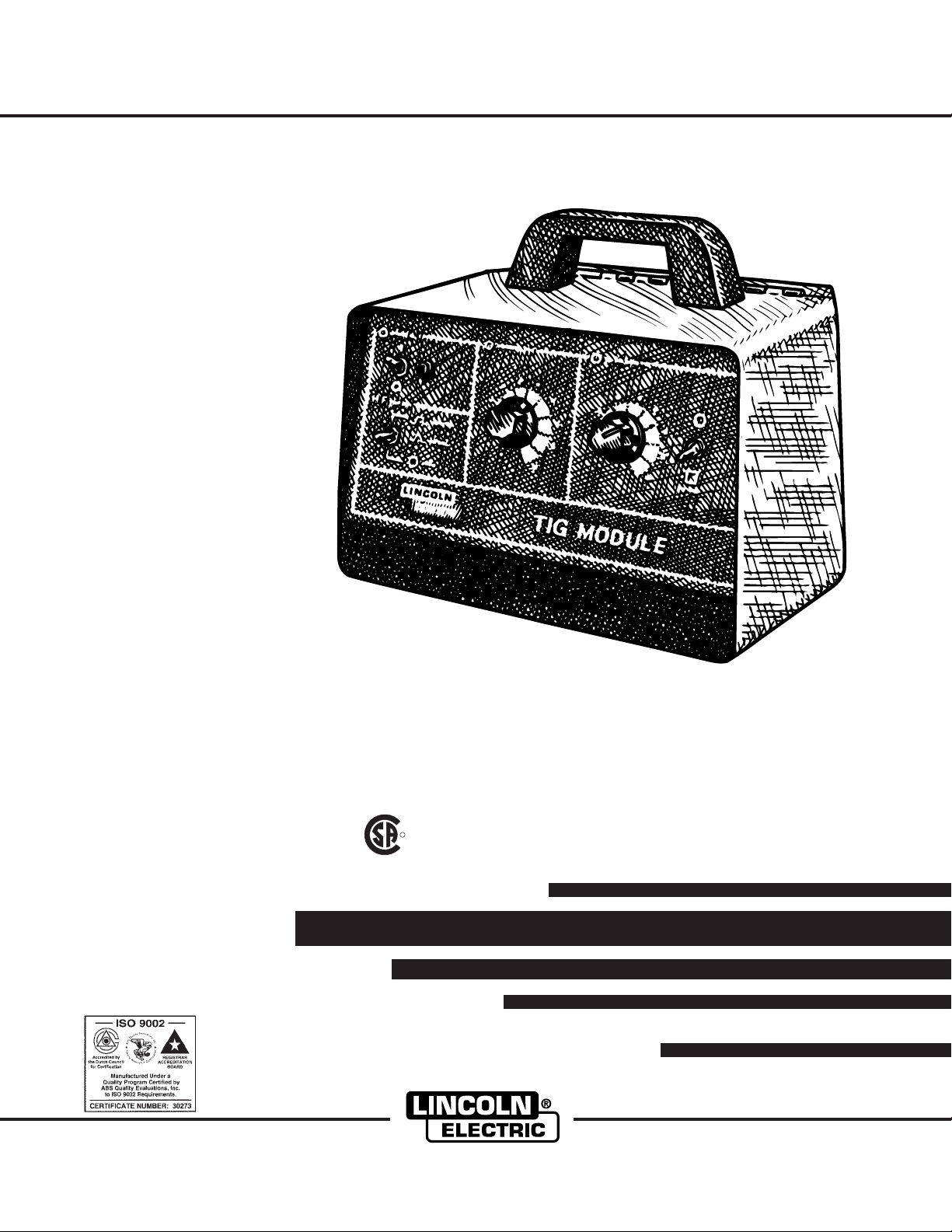
IM528-B
March, 2005
TIG Module
OPERATOR’S MANUAL
Copyright © 2005 Lincoln Global Inc.
• World's Leader in Welding and Cutting Products •
• Sales and Service through Subsidiaries and Distributors Worldwide •
Cleveland, Ohio 44117-1199 U.S.A. TEL: 216.481.8100 FAX: 216.486.1751 WEB SITE: www.lincolnelectric.com
Page 2
i
SAFETY
i
WARNING
CALIFORNIA PROPOSITION 65 WARNINGS
Diesel engine exhaust and some of its constituents
are known to the State of California to cause
cancer, birth defects, and other reproductive harm.
The Above For Diesel Engines
ARC WELDING CAN BE HAZARDOUS. PROTECT YOURSELF AND OTHERS FROM POSSIBLE SERIOUS INJURY OR DEATH.
KEEP CHILDREN AWAY. PACEMAKER WEARERS SHOULD CONSULT WITH THEIR DOCTOR BEFORE OPERATING.
Read and understand the following safety highlights. For additional safety information, it is strongly recommended that you
purchase a copy of “Safety in Welding & Cutting - ANSI Standard Z49.1” from the American Welding Society, P.O. Box
351040, Miami, Florida 33135 or CSA Standard W117.2-1974. A Free copy of “Arc Welding Safety” booklet E205 is available
from the Lincoln Electric Company, 22801 St. Clair Avenue, Cleveland, Ohio 44117-1199.
BE SURE THAT ALL INSTALLATION, OPERATION, MAINTENANCE AND REPAIR PROCEDURES ARE
PERFORMED ONLY BY QUALIFIED INDIVIDUALS.
The engine exhaust from this product contains
chemicals known to the State of California to cause
cancer, birth defects, or other reproductive harm.
The Above For Gasoline Engines
FOR ENGINE
powered equipment.
1.a. Turn the engine off before troubleshooting and maintenance
work unless the maintenance work requires it to be running.
____________________________________________________
1.b.Operate engines in open, well-ventilated
areas or vent the engine exhaust fumes
outdoors.
____________________________________________________
1.c. Do not add the fuel near an open flame
welding arc or when the engine is running.
Stop the engine and allow it to cool before
refueling to prevent spilled fuel from
vaporizing on contact with hot engine parts
and igniting. Do not spill fuel when filling
tank. If fuel is spilled, wipe it up and do not
start engine until fumes have been
eliminated.
____________________________________________________
1.d. Keep all equipment safety guards, covers and devices in
position and in good repair.Keep hands, hair, clothing and
tools away from V-belts, gears, fans and all other moving
parts when starting, operating or repairing equipment.
____________________________________________________
1.e. In some cases it may be necessary to remove safety
guards to perform required maintenance. Remove
guards only when necessary and replace them when the
maintenance requiring their removal is complete.
Always use the greatest care when working near moving
parts.
___________________________________________________
1.f. Do not put your hands near the engine fan.
Do not attempt to override the governor or
idler by pushing on the throttle control rods
while the engine is running.
1.h. To avoid scalding, do not remove the
radiator pressure cap when the engine is
hot.
ELECTRIC AND
MAGNETIC FIELDS
may be dangerous
2.a. Electric current flowing through any conductor causes
localized Electric and Magnetic Fields (EMF). Welding
current creates EMF fields around welding cables and
welding machines
2.b. EMF fields may interfere with some pacemakers, and
welders having a pacemaker should consult their physician
before welding.
2.c. Exposure to EMF fields in welding may have other health
effects which are now not known.
2.d. All welders should use the following procedures in order to
minimize exposure to EMF fields from the welding circuit:
2.d.1.
Route the electrode and work cables together - Secure
them with tape when possible.
2.d.2. Never coil the electrode lead around your body.
2.d.3. Do not place your body between the electrode and
work cables. If the electrode cable is on your right
side, the work cable should also be on your right side.
2.d.4. Connect the work cable to the workpiece as close as
possible to the area being welded.
___________________________________________________
1.g. To prevent accidentally starting gasoline engines while
turning the engine or welding generator during maintenance
work, disconnect the spark plug wires, distributor cap or
magneto wire as appropriate.
TIG MODULE
2.d.5. Do not work next to welding power source.
Mar ‘95
- i -
Page 3
ii
SAFETY
ii
ELECTRIC SHOCK can
kill.
3.a. The electrode and work (or ground) circuits
are electrically “hot” when the welder is on.
Do not touch these “hot” parts with your bare
skin or wet clothing. Wear dry, hole-free
gloves to insulate hands.
3.b. Insulate yourself from work and ground using dry insulation.
Make certain the insulation is large enough to cover your full
area of physical contact with work and ground.
In addition to the normal safety precautions, if welding
must be performed under electrically hazardous
conditions (in damp locations or while wearing wet
clothing; on metal structures such as floors, gratings or
scaffolds; when in cramped positions such as sitting,
kneeling or lying, if there is a high risk of unavoidable or
accidental contact with the workpiece or ground) use
the following equipment:
• Semiautomatic DC Constant Voltage (Wire) Welder.
• DC Manual (Stick) Welder.
• AC Welder with Reduced Voltage Control.
3.c. In semiautomatic or automatic wire welding, the electrode,
electrode reel, welding head, nozzle or semiautomatic
welding gun are also electrically “hot”.
3.d. Always be sure the work cable makes a good electrical
connection with the metal being welded. The connection
should be as close as possible to the area being welded.
3.e. Ground the work or metal to be welded to a good electrical
(earth) ground.
ARC RAYS can burn.
4.a. Use a shield with the proper filter and cover
plates to protect your eyes from sparks and
the rays of the arc when welding or observing
open arc welding. Headshield and filter lens
should conform to ANSI Z87. I standards.
4.b. Use suitable clothing made from durable flame-resistant
material to protect your skin and that of your helpers from
the arc rays.
4.c. Protect other nearby personnel with suitable, non-flammable
screening and/or warn them not to watch the arc nor expose
themselves to the arc rays or to hot spatter or metal.
FUMES AND GASES
can be dangerous.
5.a.Welding may produce fumes and gases
hazardous to health. Avoid breathing these
fumes and gases.When welding, keep
your head out of the fume. Use enough
ventilation and/or exhaust at the arc to keep
fumes and gases away from the breathing zone. When
welding with electrodes which require special
ventilation such as stainless or hard facing (see
instructions on container or MSDS) or on lead or
cadmium plated steel and other metals or coatings
which produce highly toxic fumes, keep exposure as
low as possible and below Threshold Limit Values (TLV)
using local exhaust or mechanical ventilation. In
confined spaces or in some circumstances, outdoors, a
respirator may be required. Additional precautions are
also required when welding on galvanized steel.
3.f.
Maintain the electrode holder, work clamp, welding cable and
welding machine in good, safe operating condition. Replace
damaged insulation.
3.g. Never dip the electrode in water for cooling.
3.h. Never simultaneously touch electrically “hot” parts of
electrode holders connected to two welders because voltage
between the two can be the total of the open circuit voltage
of both welders.
3.i. When working above floor level, use a safety belt to protect
yourself from a fall should you get a shock.
3.j. Also see Items 6.c. and 8.
5.b.
Do not weld in locations near chlorinated hydrocarbon
coming from degreasing, cleaning or spraying operations.
The heat and rays of the arc can react with solvent vapors
form phosgene, a highly toxic gas, and other irritating
products.
5.c. Shielding gases used for arc welding can displace air and
cause injury or death. Always use enough ventilation,
especially in confined areas, to insure breathing air is safe.
5.d. Read and understand the manufacturer’s instructions for this
equipment and the consumables to be used, including the
material safety data sheet (MSDS) and follow your
employer’s safety practices. MSDS forms are available from
your welding distributor or from the manufacturer.
5.e. Also see item 1.b.
Mar ‘95
vapors
to
- ii -
TIG MODULE
Page 4
iii
SAFETY
iii
WELDING SPARKS can
cause fire or explosion.
6.a.
Remove fire hazards from the welding area.
If this is not possible, cover them to prevent
the welding sparks from starting a fire.
materials from welding can easily go through small cracks
and openings to adjacent areas. Avoid welding near
hydraulic lines. Have a fire extinguisher readily available.
6.b. Where compressed gases are to be used at the job site,
special precautions should be used to prevent hazardous
situations. Refer to “Safety in Welding and Cutting” (ANSI
Standard Z49.1) and the operating information for the
equipment being used.
6.c. When not welding, make certain no part of the electrode
circuit is touching the work or ground. Accidental contact
can cause overheating and create a fire hazard.
6.d. Do not heat, cut or weld tanks, drums or containers until the
proper steps have been taken to insure that such procedures
will not cause flammable or toxic vapors from substances
inside. They can cause an explosion even
been “cleaned”. For information, purchase “Recommended
Safe Practices for the
Containers and Piping That Have Held Hazardous
Substances”, AWS F4.1 from the American Welding Society
(see address above).
6.e. Vent hollow castings or containers before heating, cutting or
welding. They may explode.
Sparks and spatter are thrown from the welding arc. Wear oil
6.f.
free protective garments such as leather gloves, heavy shirt,
cuffless trousers, high shoes and a cap over your hair. Wear
ear plugs when welding out of position or in confined places.
Always wear safety glasses with side shields when in a
welding area.
6.g. Connect the work cable to the work as close to the welding
area as practical. Work cables connected to the building
framework or other locations away from the welding area
increase the possibility of the welding current passing
through lifting chains, crane cables or other alternate
circuits. This can create fire hazards or overheat lifting
chains or cables until they fail.
6.h. Also see item 1.c.
Remember that welding sparks and hot
though
they have
Preparation
for Welding and Cutting of
CYLINDER may explode
if damaged.
7.a. Use only compressed gas cylinders
containing the correct shielding gas for the
process used and properly operating
regulators designed for the gas and
pressure used. All hoses, fittings, etc. should be suitable for
the application and maintained in good condition.
7.b. Always keep cylinders in an upright position securely
chained to an undercarriage or fixed support.
7.c. Cylinders should be located:
• Away from areas where they may be struck or subjected to
physical damage.
• A safe distance from arc welding or cutting operations and
any other source of heat, sparks, or flame.
7.d. Never allow the electrode, electrode holder or any other
electrically “hot” parts to touch a cylinder.
7.e. Keep your head and face away from the cylinder valve outlet
when opening the cylinder valve.
7.f. Valve protection caps should always be in place and hand
tight except when the cylinder is in use or connected for
use.
7.g. Read and follow the instructions on compressed gas
cylinders, associated equipment, and CGA publication P-l,
“Precautions for Safe Handling of Compressed Gases in
Cylinders,” available from the Compressed Gas Association
1235 Jefferson Davis Highway, Arlington, VA 22202.
FOR ELECTRICALLY
powered equipment.
8.a. Turn off input power using the disconnect
switch at the fuse box before working on
the equipment.
8.b. Install equipment in accordance with the U.S. National
Electrical Code, all local codes and the manufacturer’s
recommendations.
8.c. Ground the equipment in accordance with the U.S. National
Electrical Code and the manufacturer’s recommendations.
TIG MODULE
Mar ‘95
- iii -
Page 5

iv
SAFETY
iv
PRÉCAUTIONS DE SÛRETÉ
Pour votre propre protection lire et observer toutes les
instructions et les précautions de sû reté specifiques qui
parraissent dans ce manuel aussi bien que les précautions de
sûreté générales suivantes:
Sûreté Pour Soudage A L’Arc
1. Protegez-vous contre la secousse électrique:
a. Les circuits à l’électrode et à la piéce sont sous tension
quand la machine à souder est en marche. Eviter toujours
tout contact entre les parties sous tension et la peau nue
ou les vétements mouillés. Porter des gants secs et sans
trous pour isoler les mains.
b. Faire trés attention de bien s’isoler de la masse quand on
soude dans des endroits humides, ou sur un plancher
metallique ou des grilles metalliques, principalement dans
les positions assis ou couché pour lesquelles une
grande partie du corps peut être en contact avec la
masse.
c. Maintenir le porte-électrode, la pince de masse, le câble
de soudage et la machine à souder en bon et sûr état
defonctionnement.
d.Ne jamais plonger le porte-électrode dans l’eau pour le
refroidir.
e. Ne jamais toucher simultanément les parties sous tension
des porte-électrodes connectés à deux machines à
souder parce que la tension entre les deux pinces peut
être le total de la tension à vide des deux machines.
f. Si on utilise la machine à souder comme une source de
courant pour soudage semi-automatique, ces precautions
pour le porte-électrode s
soudage.
’applicuent aussi au pistolet de
5. Toujours porter des lunettes de sécurité dans la zone de
soudage. Utiliser des lunettes avec écrans lateraux dans les
zones où l’on pique le laitier.
6. Eloigner les matériaux inflammables ou les recouvrir afin de
prévenir tout risque d’incendie dû aux étincelles.
7. Quand on ne soude pas, poser la pince à une endroit isolé de
la masse. Un court-circuit accidental peut provoquer un
échauffement et un risque d’incendie.
8. S’assurer que la masse est connectée le plus prés possible
de la zone de travail qu’il est pratique de le faire. Si on place
la masse sur la charpente de la construction ou d’autres
endroits éloignés de la zone de travail, on augmente le risque
de voir passer le courant de soudage par les chaines de
levage, câbles de grue, ou autres circuits. Cela peut
provoquer des risques d’incendie ou d’echauffement des
chaines et des câbles jusqu’à ce qu’ils se rompent.
9. Assurer une ventilation suffisante dans la zone de soudage.
Ceci est particuliérement important pour le soudage de tôles
galvanisées plombées, ou cadmiées ou tout autre métal qui
produit des fumeés toxiques.
10. Ne pas souder en présence de vapeurs de chlore provenant
d’opérations de dégraissage, nettoyage ou pistolage. La
chaleur ou les rayons de l’arc peuvent réagir avec les
vapeurs du solvant pour produire du phosg
fortement toxique) ou autres produits irritants.
11. Pour obtenir de plus amples renseignements sur la sûreté,
voir le code “Code for safety in welding and cutting” CSA
Standard W 117.2-1974.
éne (gas
2. Dans le cas de travail au dessus du niveau du sol, se
protéger contre les chutes dans le cas ou on recoit un choc.
Ne jamais enrouler le câble-électrode autour de n’importe
quelle partie du corps.
3. Un coup d’arc peut être plus sévère qu’un coup de soliel,
donc:
a. Utiliser un bon masque avec un verre filtrant approprié
ainsi qu’un verre blanc afin de se protéger les yeux du
rayonnement de l’arc et des projections quand on soude
ou quand on regarde l’arc.
b. Porter des vêtements convenables afin de protéger la
peau de soudeur et des aides contre le rayonnement de
l‘arc.
c. Protéger l’autre personnel travaillant à proximité au
soudage à l’aide d’écrans approprié s et non-
inflammables.
4. Des gouttes de laitier en fusion sont émises de l’arc de
soudage. Se protéger avec des vêtements de protection
libres de l’huile, tels que les gants en cuir, chemise épaisse,
pantalons sans revers, et chaussures montantes.
PRÉCAUTIONS DE SÛRETÉ POUR
LES MACHINES À SOUDER À
TRANSFORMATEUR ET À
REDRESSEUR
1. Relier à la terre le chassis du poste conformement au code
de l’électricité et aux recommendations du fabricant. Le
dispositif de montage ou la piece à souder doit être branché
à une bonne mise à la terre.
2. Autant que possible, I’installation et l’entretien du poste
seront effectués par un électricien qualifié.
3. Avant de faires des travaux à l’interieur de poste, la
debrancher à l’interrupteur à la boite de fusibles.
4. Garder tous les couvercles et dispositifs de sûretéà leur
place.
Mar. ‘93
- iv -
TIG MODULE
Page 6
for selecting a QUALITY product by Lincoln Electric. We want you
Thank You
to take pride in operating this Lincoln Electric Company product
••• as much pride as we have in bringing this product to you!
Please Examine Carton and Equipment For Damage Immediately
When this equipment is shipped, title passes to the purchaser upon receipt by the carrier. Consequently, Claims
for material damaged in shipment must be made by the purchaser against the transportation company at the
time the shipment is received.
Please record your equipment identification information below for future reference. This information can be
found on your machine nameplate.
Product _________________________________________________________________________________
Model Number ___________________________________________________________________________
Code Number or Date Code_________________________________________________________________
Serial Number____________________________________________________________________________
Date Purchased___________________________________________________________________________
Where Purchased_________________________________________________________________________
vv
Whenever you request replacement parts or information on this equipment, always supply the information you
have recorded above. The code number is especially important when identifying the correct replacement parts.
On-Line Product Registration
- Register your machine with Lincoln Electric either via fax or over the Internet.
• For faxing: Complete the form on the back of the warranty statement included in the literature packet
accompanying this machine and fax the form per the instructions printed on it.
• For On-Line Registration: Go to our
“Product Registration”. Please complete the form and submit your registration.
Read this Operators Manual completely before attempting to use this equipment. Save this manual and keep it
handy for quick reference. Pay particular attention to the safety instructions we have provided for your protection.
The level of seriousness to be applied to each is explained below:
WEB SITE at www.lincolnelectric.com. Choose “Quick Links” and then
WARNING
This statement appears where the information must be followed exactly to avoid serious personal injury or
loss of life.
CAUTION
This statement appears where the information must be followed to avoid minor personal injury or damage to
this equipment.
TIG MODULE
- v -
Page 7

TABLE OF CONTENTS
Page
Safety .....................................................................................................................i-iv
Installation................................................................................................................1-17
Technical Specifications ............................................................................................1
Input and Rated Capacities
Recommended Welding Cables
Physical Dimensions
Location .....................................................................................................................2
Environmental Protection...........................................................................................2
High Frequency Interference Protection....................................................................2
Supply Connections...................................................................................................3
Input & Output Connections.......................................................................................3
Installation of Field Installed Accessories..................................................................4
Installation with a Power Source...........................................................................5-17
Ranger 8 Installation...........................................................................................5-8
Ranger 9 Installation.........................................................................................9-10
Ranger 10 & Ranger 300 D Installation..........................................................11-12
Ranger 10-LX & Ranger 300 DLX Installation................................................13-14
Installation with other Lincoln Power Sources ................................................15-17
Operation................................................................................................................18-30
Safety Instructions ...................................................................................................18
Graphic Symbols......................................................................................................19
Product Description..................................................................................................20
Recommended Processes and Equipment..............................................................20
Design Summary .....................................................................................................20
Controls and Settings .........................................................................................21-22
Ranger 8 Operation............................................................................................23-24
Figure 9....................................................................................................................25
Ranger 9 Operation .................................................................................................26
Ranger 10 & Ranger 300 D Operation.....................................................................27
Ranger 10-LX & Ranger 300 DLX Operation...........................................................28
Operation on other Lincoln Power Sources.............................................................29
TIG Welding Information..........................................................................................30
Accessories.................................................................................................................31
Maintenance ................................................................................................................32
Safety Precautions...................................................................................................32
Periodic Maintenance ..............................................................................................32
Troubleshooting ....................................................................................................33-36
How To Use Troubleshooting Guide........................................................................33
Troubleshooting Guide .......................................................................................34-36
Wiring Diagram ...........................................................................................................37
Parts Manual ...................................................................................................Appendix
- vi -
TIG MODULE
Page 8
INSTALLATION
TECHNICAL SPECIFICATIONS - TIG MODULE
INPUT - SINGLE PHASE ONLY
Standard
Voltage
Input Current
Code
Number
115 VAC 50/60
(60VAC TO 130 VAC) 50/60 HZ.
(MIN. TO MAX.)
Duty Cycle
100%
60%
20%
RECOMMENDED WELDING CABLES
Duty Cycle
100%
60%
1.3 amperes
RATED CAPACITIES
Amps
200 amps AC/DC
300 amps AC/DC
400 amps AC/DC
Amps
200 amps AC/DC
300 amps AC/DC
10135
10203
10284
11010
Total Capacity Range
15 - 400 amps AC/DC
Cable sizes* (mm2)
#2 AWG (30)
#1 AWG (35)
20%
(*) Correct Cable size if the cable length is 150 feet (45.7 meters) or less.
PHYSICAL DIMENSIONS
Height Width Depth Weight
12.0 in. 15.0 in. 10.5 in. 33 lbs
305 mm 381 mm 267 mm (15 kg)
Insulation Class 155(F)
400 amps AC/DC
#1/0 AWG (50)
TIG MODULE
– 1 –
Page 9

INSTALLATION
Read entire installation section before starting
installation.
Safety Precautions
WARNING
ELECTRIC SHOCK can kill.
• Only qualified personnel should perform
this installation.
• Turn the Power Source input power OFF
at the disconnect switch or stop the
engine before attempting to connect the
TIG Module
• Do not touch electrically hot parts.
Users should familiarize themselves with Figure 8,
Rear Connections, in the Operating Section of this
manual before proceeding.
LOCATION
The TIG Module can be mounted in or carried to any
convenient location. It is designed to be portable. If
placed on the roof of engine welders, it must be
mounted securely. A Docking Kit option is available
for this purpose. See the Accessories section.
ENVIRONMENTAL PROTECTION
2. Direct interference radiated from the welding leads.
3. Direct interference radiated from feedback into the
power lines.
4. Interference from reradiation of “ pickup” by
ungrounded metallic objects.
Keeping these contributing factors in mind, installing
equipment per the following instructions should
minimize problems.
1. Keep the power source input supply lines as short
as possible and completely enclose them in rigid
metallic conduit or equivalent shielding for a
minimum distance of 50 feet (15.2 m). There
should be good electrical contact between this
conduit and the welder. Both ends of the conduit
should be connected to a driven ground and the
entire length should be continuous.
2. Keep the work and electrode leads as short as
possible and as close together as possible.
Lengths should not exceed 25 feet (7.6 m). Tape
the leads together when practical.
3. Be sure the torch and work cable rubber coverings
are free of cuts and cracks that allow high
frequency leakage. Cables with high natural
rubber content, such as Lincoln Stable-Arc® better
resist high frequency leakage than neoprene and
other synthetic rubber insulated cables.
This accessory qualifies for an IP23 rating. It is suited
for use in damp, dirty and dusty locations. (In
locations where there are large amounts of conductive
metal or salt particles in the air, additional
maintenance may be required.) It is protected against
rainfall. Excessive moisture can, however, cause
short term operational difficulties. Difficulties can
occur with the spark gap; it may not “spark” when the
unit is first turned on after prolonged exposure to
moisture. Usually, allowing the unit to operate for 5 to
15 minutes will allow the spark gap to dry out, and
return to normal operation.
HIGH FREQUENCY INTERFERENCE
4. Keep the torch in good repair and all connections
tight to reduce high frequency leakage.
5. The work terminal must be connected to a ground
within ten feet of the welder, using one of the
following methods:
a) A metal underground water pipe in direct
contact with the earth for ten feet or more.
b) A 3/4” (19 mm) galvanized pipe or conduit
or a 5/8” (16 mm) solid galvanized iron or
steel or copper rod driven at least eight
feet into the ground.
PROTECTION
The ground should be securely made and the
Since the spark gap oscillator in the TIG Module is
similar to a radio transmitter, improper installation can
result in radio and TV interference or problems with
nearby electronic equipment.
Radiated interference can develop in the following
four ways:
1. Direct interference radiated from the welder and
the TIG Module.
grounding cable should be as short as possible using
cable of the same size as the work cable, or larger.
Grounding to the building frame electrical conduit or a
long pipe system can result in reradiation, effectively
making these members radiating antennas.
NOTE: The welder frame MUST also be grounded.
The work terminal ground does not ground
the welder frame.
– 2 –
TIG MODULE
Page 10

INSTALLATION
6. Keep all access panels and covers securely in
place.
7. All electrical conductors within 50 feet (15.2 m) of
the welder should be enclosed in grounded rigid
metallic conduit or equivalent shielding. Flexible
helically-wrapped metallic conduit is generally not
suitable.
8. When the welder is enclosed in a metal building,
several good earth driven electrical grounds (as in
5 (b)) around the periphery of the building are
recommended.
SUPPLY CONNECTIONS
Control cables are needed to connect the TIG
Module’s 9-pin Input Receptacle to the power source.
Four different cables are available. The proper choice
of cable depends on the power source being used.
Included in this report are charts which specify which
cable is used with a particular power source. The
cables come in standard 5 ft.(1.5m) lengths. 22(6.7m)
and 45(13.7) ft. extensions are available.
Note that two of the studs are labeled “FROM
POWER SOURCE”; these are to be connected to
the power source work and electrode terminals. If
the power source output terminals are not labeled
“WORK” and “ELECTRODE”, the TIG Module
“FROM POWER SOURCE ELECTRODE”
terminal should go to the power source output
terminal which matches the desired welding
polarity. This is the negative (-) terminal when
welding DC-. The choice of power source
terminal will have no effect when welding AC.
TIG Torch and Workpiece Connections
One terminal is labeled “TO TIG TORCH”. Use
that terminal for the TIG torch connection. TIG
torches come in 12.5ft.(3.8m) and 25ft.(7.6m)
lengths; use the shorter size whenever possible to
minimize the possibility of high frequency
interference.
The last terminal is labeled “TO WORKPIECE”.
Use short lengths whenever possible to minimize
the possibility of high frequency interference.
Input power should be nominally 115 volts AC, but the
TIG Module will operate properly on any AC voltage
from 60 to 130 volts, 50 or 60 Hz. Input current draw
is 1.3 amps at 115 volts.
INPUT AND OUTPUT CONNECTIONS
Input Connections
The user must provide welding cables for the
connections between the work and electrode
terminals of the power source, and the “FROM
POWER SOURCE WORK” and “FROM POWER
SOURCE ELECTRODE” terminals of the TIG
Module. All connections are made with 1/2-13
threaded stud output terminals. Choose cables
according to the output currents and duty cycles
listed below.
200 Amps 100% Duty Cycle #2 AWG(30mm
(minimum) Cable
300 Amps 60% Duty Cycle #1 AWG(35mm2)
(minimum) Cable
400 Amps 20% Duty Cycle #1/0 AWG(50mm
(minimum) Cable
These ratings are for cables lengths of 150
ft.(46.0m) or less.
2
)
2
)
Shielding Gas Connections
The gas valve connections are labeled “GAS
INPUT” and “GAS OUTPUT”. Any torch and gas
supply conforming to Compressed Gas
Association (CGA) standards can be connected
via the 5/8-18 right hand threaded fittings. The
cylinder of shielding gas must be equipped with a
regulator and flowmeter. Install a hose between
the flowmeter and the input fitting.
Water Valve Connection
The optional K844-1 Water Valve Kit can be
installed in the TIG Module to provide on/off flow
control for cooling water. The water valve opens
and closes at the same time as the gas valve, so
cooling water flows during the afterflow period.
Connections are made via the two 5/8-18 left
hand threaded connections. If using a watercooled torch with a free running water supply,
install a water line between the water supply and
the “WATER INPUT” fitting on the TIG Module.
Include a strainer in the supply line to prevent dirt
particles from obstructing the water flow in the
valve and cooling chamber of the TIG torch.
Failure to do so could result in overheating of the
water-cooled torch. Connect the torch water line
to the “WATER OUTPUT” fitting. Use a
nonmetallic drain line from the TIG torch power
block to the drain.
TIG MODULE
– 3 –
Page 11

INSTALLATION
If using a water cooled torch with a water cooler,
do not install the water valve. It will block the
water flow, possibly damaging the pump.
Magnum water coolers are an exception to this
rule. Refer to the manufacturer’s instructions
provided with the cooler.
INSTALLATION OF FIELD INSTALLED
ACCESSORIES
Installation of the K963 Hand Amptrol, K870 Foot
Amptrol, and K814 Arc Start Switch is as follows:
Connect the 6-pin MS-type circular connector to
the Remote Receptacle on the TIG Module.
Secure with the threaded collar.
Installation of the K936-[ ] Input Cables and K937-[ ]
Extension Cables is as follows:
Connect the 9-socket MS-type circular connector
on the Input Cable to the Input Receptacle on the
TIG Module. Secure with the threaded collar. If
one or more K937-[ ] Extension Cables are used,
connect them between the TIG Module and the
K936-[ ] Input cable.
Installation instructions for the K938-1 Contactor Kit,
K844-1 Water Valve Kit and the K939-1 Docking Kit
are included with those kits.
– 4 –
TIG MODULE
Page 12

INSTALLATION
INSTALLATION WITH A POWER SOURCE
Ranger 8 Installation
Tables 1 and 2 list the required and optional
equipment for installing and operating the TIG
Module with a Ranger 8. Table 1 is for the
Ranger 8, and table 2 is for the Ranger 8 with the
K892-1 Remote Kit installed. The Remote Kit
installation is identified by the presence of a 6-pin
remote connector located between the output
studs.
RANGER 8 (WITH NO K892-1 REMOTE KIT) AND THE TIG MODULE
REQUIRED EQUIPMENT
Control
Cable
Contactor
Kit
Work and
Electrode
Leads from
Ranger 8 to
TIG Module
TIG
Torch
Refer to the Connection Diagrams Figures 1 and
2. Figure 1 is for the Ranger 8, and figure 2, for
the Ranger 8 with the K892-1 Remote Kit
installed. Make sure all connections are tight
before proceeding.
Work
Lead
Shielding Gas,
Regulator,
Flowmeter
Arc Start
Switch
K936-4
9-pin to
115V Plug
Control
Cable
Extension
K937 - [ ]
Extension
9-pin to 9-pin
K938-1
Field
Installed
User Supplied;
Length as
Req’d. Cable
Sized to Match
Current and
Duty Cycle
User
Supplied
User Supplied;
Length as
Req’d. Cable
Sized to Match
Current and
Duty Cycle
User
Supplied
RANGER 8 (WITH NO K892-1 REMOTE KIT) AND THE TIG MODULE
OPTIONAL EQUIPMENT
Water
Valve
K844-1 K939-1
Docking
Kit
Mounts to
Ranger 8 Roof
TABLE 1
K814
TIG MODULE
– 5 –
Page 13

INSTALLATION
Only qualified personnel should install,use
Keep guards in place.
or service this equipment.
Keep away from moving parts.
K814 ARC START SWITCH
12-1-94
M17530
40
40
4
4
L9
L9
TM
TM
LOCAL
LOCAL
SERIAL NO.
SERIAL NO.
SWITCH
CURRENT
CONTROL
REMOTE AMPTROL
REMOTE AMPTROL
WARNING
WARNING
CODE
CODE
8
8
7
7
9
9
100%
100%
6
6
10
10
60%
60%
250A 180A
250A 180A
5
5
20%
20%
350A
350A
0
0
4
4
1
1
3
3
2
2
CURRENT CONTROL
20A TO 350A
20A TO 350A
RATED CAPACITY
RATED CAPACITY
45
45
40
40
50
50
55 S
55 S
35
35
2
2
30
30
5
5
AFTERFLOW
25
25
10
10
20
20
15
15
THE LINCOLN ELECTRIC CO. CLEVELAND, OHIO U.S.A.
THE LINCOLN ELECTRIC CO. CLEVELAND, OHIO U.S.A.
1
1
START ONLY
START ONLY
INPUT
WARNING
Do not operate with panels open.
Disconnect NEGATIVE (-) BATTERY LEAD
before servicing.
Do not touch electrically live parts.
FIGURE 1: RANGER 8 / TIG MODULE CONNECTION DIAGRAM
INPUT
O
O
OFF
OFF
HF
HF
115 V 1.3 A 50/60 Hz
115 V 1.3 A 50/60 Hz
R
R
CONTINUOUS
CONTINUOUS
HIGH FREQUENCY
ELECTRIC
ELECTRIC
MODEL
MODEL
POWER
LINCOLN
LINCOLN
PORTABLE HI-FREQ
PORTABLE HI-FREQ
ON
ON
OFF
OFF
INPUT
FITTING
TO GAS
WELDING CABLES MUST BE PROPERLY SIZED FOR THE CURRENT AND DUTY CYCLE OF APPLICATION
REGULATOR
FLOWMETER
CYLINDER
ARGON GAS
– 6 –
TIG MODULE
NOTE: This diagram is for reference only. It was accurate at the time of printing , however Lincoln Electric reserves the right to make improvements and modifications
as necessary, if you supect this information to be inaccurate, write to the Service Department for a replacement. Give the equipment code number..
Page 14

INSTALLATION
RANGER 8 (WITH THE OPTIONAL K892-1 REMOTE KIT INSTALLED) AND THE TIG MODULE
REQUIRED EQUIPMENT
Control
Cable
K936-3
9-pin to
6-pin
plus
115V Plug
RANGER 8 (WITH THE OPTIONAL REMOTE KIT INSTALLED) AND THE TIG MODULE
Control
Cable
Extension
Contactor
Kit
K938-1
Field
Installed
Water
Valve
Work and
Electrode
Leads from
Ranger 8 to
TIG Module
User Supplied;
Length as
Req’d. Cable
Sized to Match
Current and
Duty Cycle
OPTIONAL EQUIPMENT
Arc Start
Switch
TIG
Torch
User
Supplied
Hand
Amptrol
Work
Lead
User Supplied;
Length as
Req’d. Cable
Sized to Match
Current and
Duty Cycle
Foot
Amptrol
Shielding Gas,
Regulator,
Flowmeter
User
Supplied
Docking
Kit
Arc Start
Switch
See
Optional
Equipment
Below
K937 - [ ]
Extension
9-pin to 9-pin
K844-1 K814 K963 K870 K939-1
Mounts to
Ranger 8 Roof
TABLE 2
TIG MODULE
– 7 –
Page 15

INSTALLATION
-OR-
-OR-
4-19-96D
M17531
Only qualified personnel should install,use
Keep guards in place.
WARNING
or service this equipment.
Keep away from moving parts.
LOCAL
LOCAL
SERIAL NO.
SERIAL NO.
CODE
CODE
100%
100%
6
6
60%
60%
250A 180A
250A 180A
5
5
20%
20%
350A
350A
4
4
20A TO 350A
20A TO 350A
RATED CAPACITY
RATED CAPACITY
35
35
30
30
25
25
1
1
INPUT
INPUT
115 V 1.3 A 50/60 Hz
115 V 1.3 A 50/60 Hz
CONTINUOUS
CONTINUOUS
MODEL
MODEL
PORTABLE HI-FREQ
PORTABLE HI-FREQ
ON
ON
K870 FOOT AMPTROL
40
40
4
4
L9
L9
TM
TM
SWITCH
SWITCH
CURRENT
CURRENT
CONTROL
CONTROL
REMOTE AMPTROL
REMOTE AMPTROL
WARNING
WARNING
8
8
7
7
9
9
10
10
0
0
1
1
3
3
2
2
CURRENT CONTROL
CURRENT CONTROL
45
45
40
40
50
50
55 S
55 S
2
2
5
5
AFTERFLOW
AFTERFLOW
10
10
20
20
15
15
THE LINCOLN ELECTRIC CO. CLEVELAND, OHIO U.S.A.
THE LINCOLN ELECTRIC CO. CLEVELAND, OHIO U.S.A.
START ONLY
START ONLY
O
O
OFF
OFF
HF
HF
R
R
HIGH FREQUENCY
HIGH FREQUENCY
ELECTRIC
ELECTRIC
POWER
POWER
LINCOLN
LINCOLN
OFF
OFF
K963 HAND AMPTROL
K814 ARC START SWITCH
Do not operate with panels open.
Disconnect NEGATIVE (-) BATTERY LEAD
before servicing.
Do not touch electrically live parts.
INPUT
FITTING
TO GAS
WELDING CABLES MUST BE PROPERLY SIZED FOR THE CURRENT AND DUTY CYCLE OF APPLICATION
FIGURE 2: RANGER 8 / K892-1 REMOTE KIT / TIG MODULE CONNECTION DIAGRAM
REGULATOR
FLOWMETER
CYLINDER
ARGON GAS
– 8 –
TIG MODULE
NOTE: This diagram is for reference only. It was accurate at the time of printing , however Lincoln Electric reserves the right to make improvements and modifications
as necessary, if you supect this information to be inaccurate, write to the Service Department for a replacement. Give the equipment code number..
Page 16

INSTALLATION
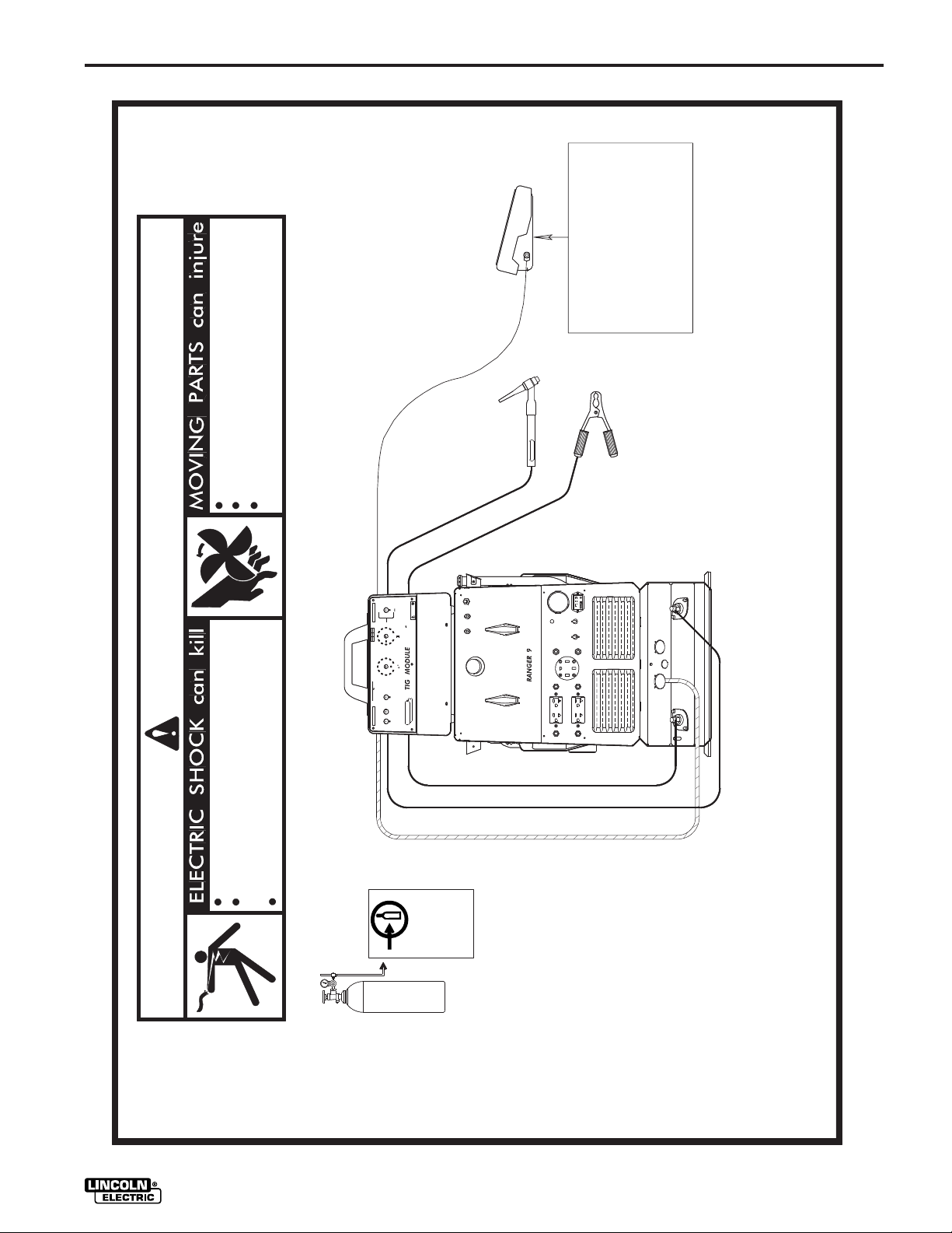
Ranger 9 Installation
Table 3 lists the required and optional equipment
for installing and operating the TIG Module with a
Ranger 9.
Refer to Figure 3 for the TIG Module/Ranger 9
connection diagram. Make sure all connections
are tight before proceeding.
RANGER 9 AND THE TIG MODULE
REQUIRED EQUIPMENT
Control
Cable
K936-1
9-pin to 14-pin
Control Cable
Extension
Work and
Electrode
Leads from
Ranger 9 to
TIG Module
User Supplied;
Length as Req’d.
Cable Sized to
Match Current
and Duty Cycle
RANGER 9 AND THE TIG MODULE
Water
Valve
TIG
Torch
User
Supplied
Work
Lead
User Supplied;
Length as Req’d.
Cable Sized to
Match Current
and Duty Cycle
OPTIONAL EQUIPMENT
Arc Start
Switch
Hand
Amptrol
Shielding Gas,
Regulator,
Flowmeter
User
Supplied
Foot
Amptrol
Arc Start
Switch
- OR -
Amptrol
See
Optional
Equipment
Below
Docking
Kit
K937 - [ ]
Extension
9-pin to 9-pin
TIG MODULE
K844-1
Field
Installed
K814 K963 K870 K939-1
Mounts to
Ranger 9 Roof
TABLE 3
– 9 –
Page 17
INSTALLATION
-OR-
-OR-
4-19-96D
M17532
Only qualified personnel should install,use
Keep guards in place.
WARNING
or service this equipment.
Keep away from moving parts.
LOCAL
LOCAL
SERIAL NO.
SERIAL NO.
CODE
CODE
100%
100%
6
6
60%
60%
250A 180A
250A 180A
5
5
20%
20%
350A
350A
4
4
20A TO 350A
20A TO 350A
RATED CAPACITY
RATED CAPACITY
35
35
30
30
25
25
1
1
INPUT
INPUT
115 V 1.3 A 50/60 Hz
115 V 1.3 A 50/60 Hz
CONTINUOUS
CONTINUOUS
MODEL
MODEL
PORTABLE HI-FREQ
PORTABLE HI-FREQ
ON
ON
K870 FOOT AMPTROL
L9440
L9440
TM
TM
SWITCH
SWITCH
CURRENT
CURRENT
CONTROL
CONTROL
REMOTE AMPTROL
REMOTE AMPTROL
WARNING
WARNING
8
8
7
7
9
9
10
10
0
0
1
1
3
3
2
2
CURRENT CONTROL
CURRENT CONTROL
45
45
40
40
50
50
55 S
55 S
2
2
5
5
AFTERFLOW
AFTERFLOW
10
10
20
20
15
15
THE LINCOLN ELECTRIC CO. CLEVELAND, OHIO U.S.A.
THE LINCOLN ELECTRIC CO. CLEVELAND, OHIO U.S.A.
START ONLY
START ONLY
O
O
OFF
OFF
HF
HF
R
R
HIGH FREQUENCY
HIGH FREQUENCY
ELECTRIC
ELECTRIC
POWER
POWER
LINCOLN
LINCOLN
OFF
OFF
K963 HAND AMPTROL
K814 ARC START SWITCH
Do not operate with panels open.
Disconnect NEGATIVE (-) BATTERY LEAD
before servicing.
Do not touch electrically live parts.
INPUT
FITTING
FIGURE 3: RANGER 9 / TIG MODULE CONNECTION DIAGRAM
REGULATOR
FLOWMETER
TO GAS
CYLINDER
ARGON GAS
– 10 –
WELDING CABLES MUST BE PROPERLY SIZED FOR THE CURRENT AND DUTY CYCLE OF APPLICATION
NOTE: This diagram is for reference only. It was accurate at the time of printing , however Lincoln Electric reserves the right to make improvements and modifications
as necessary, if you supect this information to be inaccurate, write to the Service Department for a replacement. Give the equipment code number..
TIG MODULE
Page 18

INSTALLATION
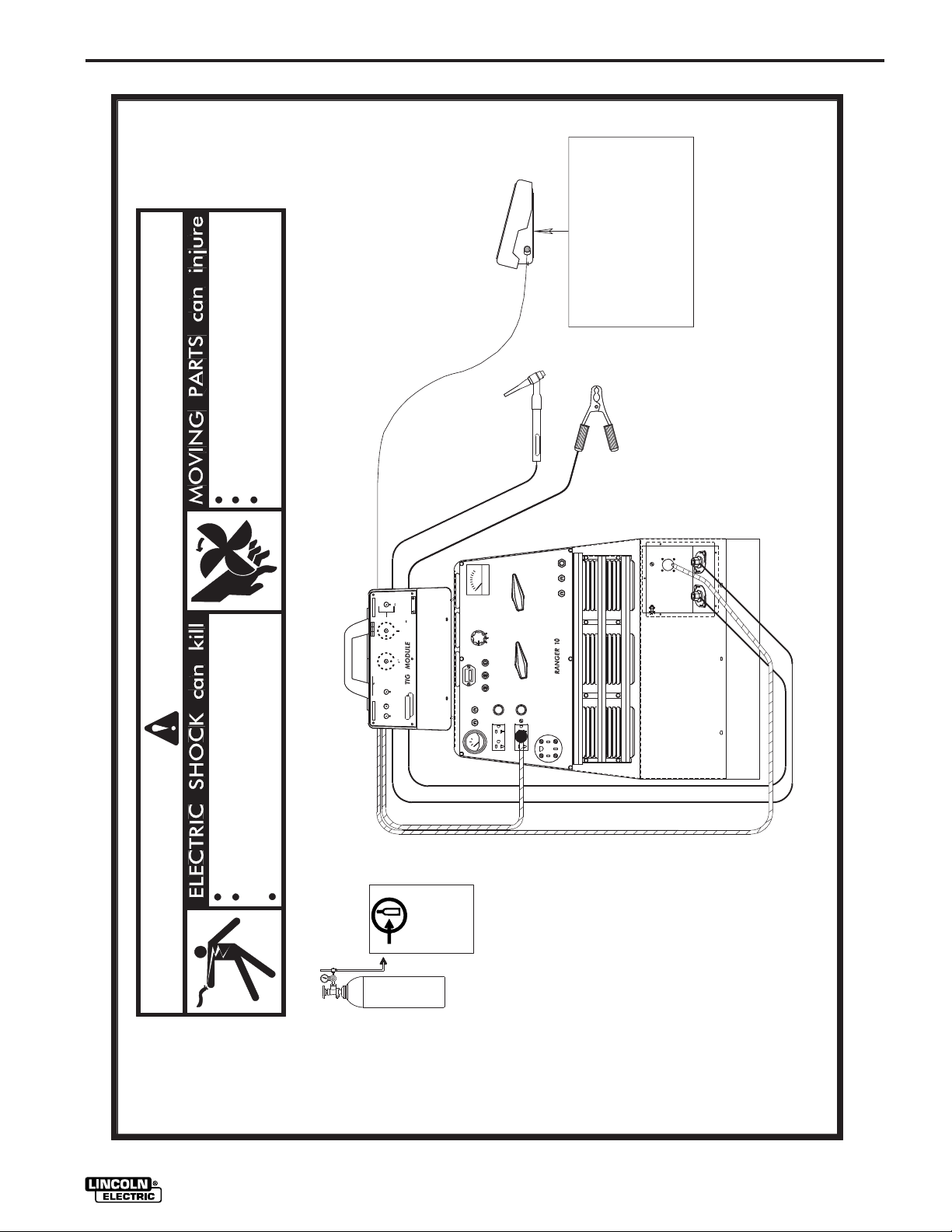
Ranger 10 and Ranger 300 D Installation
Table 4 lists the required and optional equipment
for installing and operating the TIG Module with a
Ranger 10 or Ranger 300 D.
Refer to Figure 4 for the TIG Module/Ranger 10
connection diagram and to Figure 4A for the TIG
Module/Ranger 300 D connection diagram. Make
sure all connections are tight before proceeding.
RANGER 10 / RANGER 300 D AND THE TIG MODULE
REQUIRED EQUIPMENT
Control
Cable
K936-3
9-pin to
6-pin
plus
115V Plug
Control
Cable
Extension
Contactor
Kit
K938-1
Field
Installed
Work and
Electrode
Leads from
Ranger 10 to
TIG Module
User Supplied;
Length as
Req’d. Cable
Sized to Match
Current and
Duty Cycle
TIG
Torch
User
Supplied
Work
Lead
User Supplied;
Length as
Req’d. Cable
Sized to Match
Current and
Duty Cycle
RANGER 10 / RANGER 300 D AND THE TIG MODULE
OPTIONAL EQUIPMENT
Water
Valve
Arc Start
Switch
Hand
Amptrol
Foot
Amptrol
Shielding Gas,
Regulator,
Flowmeter
User
Supplied
Docking
Kit
Arc Start
Switch
- OR -
Amptrol
See
Optional
Equipment
Below
K937 - [ ]
Extension
9-pin to 9-pin
TIG MODULE
K844-1 K814 K963 K870 K939-1
Mounts to
Ranger 10
Roof
TABLE 4
– 11 –
Page 19
INSTALLATION
-OR-
-OR-
11/96
M17533
Only qualified personnel should install,use
Keep guards in place.
WARNING
or service this equipment.
Keep away from moving parts.
LOCAL
LOCAL
SERIAL NO.
SERIAL NO.
CODE
CODE
100%
100%
6
6
60%
60%
250A 180A
250A 180A
5
5
20%
20%
350A
350A
4
4
20A TO 350A
20A TO 350A
RATED CAPACITY
RATED CAPACITY
35
35
30
30
25
25
1
1
INPUT
INPUT
115 V 1.3 A 50/60 Hz
115 V 1.3 A 50/60 Hz
CONTINUOUS
CONTINUOUS
MODEL
MODEL
PORTABLE HI-FREQ
PORTABLE HI-FREQ
ON
ON
K870 FOOT AMPTROL
0
0
44
44
9
9
L
L
TM
TM
SWITCH
SWITCH
CURRENT
CURRENT
CONTROL
CONTROL
REMOTE AMPTROL
REMOTE AMPTROL
WARNING
WARNING
8
8
7
7
9
9
10
10
0
0
1
1
3
3
2
2
CURRENT CONTROL
CURRENT CONTROL
45
45
40
40
50
50
55 S
55 S
2
2
5
5
AFTERFLOW
AFTERFLOW
10
10
20
20
15
15
THE LINCOLN ELECTRIC CO. CLEVELAND, OHIO U.S.A.
THE LINCOLN ELECTRIC CO. CLEVELAND, OHIO U.S.A.
START ONLY
START ONLY
O
O
OFF
OFF
HF
HF
R
R
HIGH FREQUENCY
HIGH FREQUENCY
ELECTRIC
ELECTRIC
POWER
POWER
LINCOLN
LINCOLN
OFF
OFF
EF
K963 HAND AMPTROL
K814 ARC START SWITCH
Do not operate with panels open.
Disconnect NEGATIVE (-) BATTERY LEAD
before servicing.
Do not touch electrically live parts.
INPUT
FITTING
FIGURE 4: RANGER 10 / TIG MODULE CONNECTION DIAGRAM
REGULATOR
FLOWMETER
TO GAS
CYLINDER
ARGON GAS
A T12246 BYPASS CAPACITOR ASBLY.
MUST BE INSTALLED IN THE RANGER 10
TO PROTECT THE RANGER 10 FROM
DAMAGE.
– 12 –
WELDING CABLES MUST BE PROPERLY
SIZED FOR THE CURRENT AND DUTY
CYCLE OF APPLICATION.
NOTE: This diagram is for reference only. It was accurate at the time of printing , however Lincoln Electric reserves the right to make improvements and modifications
as necessary, if you supect this information to be inaccurate, write to the Service Department for a replacement. Give the equipment code number..
TIG MODULE
Page 20

INSTALLATION
-OR-
-OR-
1/03
S23732-10
Only qualified personnel should install,use
Keep guards in place.
or service this equipment.
Keep away from moving parts.
[ ]
WARNING
K870 FOOT AMPTROL
K963-1 HAND AMPTROL
K814 ARC START SWITCH
6 PIN
AMPHENOL
ELECTRODE
TO WORK
Do not operate with panels open.
before servicing.
Disconnect NEGATIVE (-) BATTERY LEAD
Do not touch electrically live parts.
INPUT
TO GAS
K963-3
FITTING
CONTROL CABLE
FIGURE 4A: RANGER 300 D / TIG MODULE CONNECTION DIAGRAM
ANY INCREASE OF THE HIGH IDLE ENGINE RPM BY CHANGING THE GOVERNOR SETTING OR OVERRIDING THE THROTTLE LINKAGE WILL CAUSE
CAUTION :
TIG MODULE
REGULATOR
FLOWMETER
CYLINDER
ARGON GAS
– 12a –
APPLICATIONS. SEE OPERATING MANUAL.
N.A. WELDING CABLES MUST BE OF PROPER CAPACITY FOR THE CURRENT AND DUTY CYCLE OF IMMEDIATE AND FUTURE
AN INCREASE IN THE THE AC AUXILIARY VOLTAGE. IF THIS VOLTAGE GOES OVER 140 VOLTS, WIRE FEEDER CONTROL CIRCUITS MAY BE
THE ENGINE WELDER OPERATING MANUAL.
DAMAGED. THE ENGINE GOVERNOR SETTING IS PRE-SET AT THE FACTORY - DO NOT ADJUST ABOVE RPM SPECIFICATIONS LISTED IN
N.E. PLACE IDLER SWITCH IN "HIGH" IDLE POSITION.
N.B. USE POLARITY SWITCH TO SELECT DESIRED ELECTRODE POLARITY. POSITION THE RANGE SWITCH TO A "STICK/WELD" POSITION.
N.C. PLACE WELDER TERMINALS SWITCH TO " REMOTELY CONTROLLED" POSITION.
N.D. PLACE OUTPUT CONTROL SWITCH IN "REMOTE CONTROL" POSITION.
NOTE: This diagram is for reference only. It was accurate at the time of printing , however Lincoln Electric reserves the right to make improvements and modifications
as necessary, if you supect this information to be inaccurate, write to the Service Department for a replacement. Give the equipment code number..
Page 21

NOTES
– 12b –
TIG MODULE
Page 22

INSTALLATION
Ranger 10-LX and Ranger 300D-LX Installation
Table 5 lists the required and optional equipment
for installing and operating the TIG Module with a
Ranger 10-LX or Ranger 300D-LX.
Refer to Figure 5 for the TIG Module/Ranger 10LX connection diagram and Figure 5A for the TIG
Module/Ranger 300D-LX connection diagram.
Make sure all connections are tight before
proceeding.
RANGER 10LX / RANGER 300D-LX AND THE TIG MODULE
REQUIRED EQUIPMENT
Control
Cable
K936-1
9-pin to
14-pin
Plug
Contactor
Kit
K938-1
Field
Installed
Work and
Electrode
Leads from
Ranger 10LX
to
TIG Module
User Supplied;
Length as
Req’d. Cable
Sized to Match
Current and
Duty Cycle
TIG
Torch
User
Supplied
Work
Lead
User Supplied;
Length as
Req’d. Cable
Sized to Match
Current and
Duty Cycle
Shielding Gas,
Regulator,
Flowmeter
User
Supplied
Arc Start
Switch
- OR -
Amptrol
See
Optional
Equipment
Below
Control
Cable
Extension
K937 - [ ]
Extension
9-pin to 9-pin
TIG MODULE
RANGER 10LX / RANGER 300D-LX AND THE TIG MODULE
OPTIONAL EQUIPMENT
Water
Valve
K844-1 K814 K963 K870 K939-1
Arc Start
Switch
Hand
Amptrol
Foot
Amptrol
Docking
Kit
Mounts to
Ranger 10LX
Roof
TABLE 5
– 13 –
Page 23

INSTALLATION
-OR-
-OR-
11/96
M17534
Only qualified personnel should install,use
Keep guards in place.
WARNING
or service this equipment.
Keep away from moving parts.
LOCAL
LOCAL
SERIAL NO.
SERIAL NO.
CODE
CODE
100%
100%
6
6
60%
60%
250A 180A
250A 180A
5
5
20%
20%
350A
350A
4
4
20A TO 350A
20A TO 350A
RATED CAPACITY
RATED CAPACITY
35
35
30
30
25
25
1
1
INPUT
INPUT
115 V 1.3 A 50/60 Hz
115 V 1.3 A 50/60 Hz
CONTINUOUS
CONTINUOUS
MODEL
MODEL
PORTABLE HI-FREQ
PORTABLE HI-FREQ
ON
ON
K870 FOOT AMPTROL
440
440
L9
L9
TM
TM
SWITCH
SWITCH
CURRENT
CURRENT
CONTROL
CONTROL
REMOTE AMPTROL
REMOTE AMPTROL
WARNING
WARNING
8
8
7
7
9
9
10
10
0
0
1
1
3
3
2
2
CURRENT CONTROL
CURRENT CONTROL
45
45
40
40
50
50
55 S
55 S
2
2
5
5
AFTERFLOW
AFTERFLOW
10
10
20
20
15
15
THE LINCOLN ELECTRIC CO. CLEVELAND, OHIO U.S.A.
THE LINCOLN ELECTRIC CO. CLEVELAND, OHIO U.S.A.
START ONLY
START ONLY
O
O
OFF
OFF
HF
HF
R
R
HIGH FREQUENCY
HIGH FREQUENCY
ELECTRIC
ELECTRIC
POWER
POWER
LINCOLN
LINCOLN
OFF
OFF
EF
K963 HAND AMPTROL
K814 ARC START SWITCH
Do not operate with panels open.
Disconnect NEGATIVE (-) BATTERY LEAD
before servicing.
Do not touch electrically live parts.
INPUT
FITTING
TO GAS
FIGURE 5: RANGER 10-LX / TIG MODULE CONNECTION DIAGRAM
REGULATOR
FLOWMETER
CYLINDER
ARGON GAS
– 14 –
A T12246 BYPASS CAPACITOR ASBLY.
MUST BE INSTALLED IN THE RANGER 10
TO PROTECT THE RANGER 10 FROM
DAMAGE.
WELDING CABLES MUST BE PROPERLY
SIZED FOR THE CURRENT AND DUTY
CYCLE OF APPLICATION.
NOTE: This diagram is for reference only. It was accurate at the time of printing , however Lincoln Electric reserves the right to make improvements and modifications
as necessary, if you supect this information to be inaccurate, write to the Service Department for a replacement. Give the equipment code number..
TIG MODULE
Page 24

INSTALLATION
-OR-
-OR-
B-UF
S23732-9
Only qualified personnel should install,use
Keep guards in place.
or service this equipment.
Keep away from moving parts.
[ ]
WARNING
K870 FOOT AMPTROL
K963-1 HAND AMPTROL
K814 ARC START SWITCH
14 PIN
AMPHENOL
ELECTRODE
TO WORK
Do not operate with panels open.
before servicing.
Disconnect NEGATIVE (-) BATTERY LEAD
Do not touch electrically live parts.
K936-1
CONTROL CABLE
INPUT
FITTING
TO GAS
FIGURE 5A: RANGER 300D-LX / TIG MODULE CONNECTION DIAGRAM
AN INCREASE IN THE THE AC AUXILIARY VOLTAGE. IF THIS VOLTAGE GOES OVER 140 VOLTS, WIRE FEEDER CONTROL CIRCUITS MAY BE
ANY INCREASE OF THE HIGH IDLE ENGINE RPM BY CHANGING THE GOVERNOR SETTING OR OVERRIDING THE THROTTLE LINKAGE WILL CAUSE
CAUTION :
TIG MODULE
REGULATOR
FLOWMETER
CYLINDER
ARGON GAS
– 14a –
APPLICATIONS. SEE OPERATING MANUAL.
N.A. WELDING CABLES MUST BE OF PROPER CAPACITY FOR THE CURRENT AND DUTY CYCLE OF IMMEDIATE AND FUTURE
THE ENGINE WELDER OPERATING MANUAL.
DAMAGED. THE ENGINE GOVERNOR SETTING IS PRE-SET AT THE FACTORY - DO NOT ADJUST ABOVE RPM SPECIFICATIONS LISTED IN
N.E. PLACE IDLER SWITCH IN "HIGH" IDLE POSITION.
N.B. USE POLARITY SWITCH TO SELECT DESIRED ELECTRODE POLARITY. POSITION THE RANGE SWITCH TO A "STICK/WELD" POSITION.
N.C. PLACE WELDER TERMINALS SWITCH TO " REMOTELY CONTROLLED" POSITION.
N.D. PLACE OUTPUT CONTROL SWITCH IN "REMOTE CONTROL" POSITION.
NOTE: This diagram is for reference only. It was accurate at the time of printing , however Lincoln Electric reserves the right to make improvements and modifications
as necessary, if you supect this information to be inaccurate, write to the Service Department for a replacement. Give the equipment code number..
Page 25

NOTES
– 14b–
TIG MODULE
Page 26

INSTALLATION
Installation with other Lincoln Power
Sources
Installation consists of connecting the input work
and electrode cables, TIG torch, work lead, the
proper control cable, and an Arc Start Switch or
Amptrol. Tables 6 and 7 list the equipment
required for installing and operating the TIG
Module on various Lincoln power sources.
If the TIG Module is being used for AC TIG
welding, the TIG Module’s input power must be
properly phased with respect to the welder output
current. This would be a front panel 115VAC
receptacle for engine welders. For transformer
welders, the TIG Module must be connected to
the same phase as the welding supply. The best
way to assure this is to connect the TIG Module
input cord, properly fused, to a source of 115VAC
inside the power source. In Lincoln transformer
welders rated 250 amps and higher, this would be
the supply leads to the fan motor. Although the
TIG Module will operate on a different phase, the
AC TIG arc will be less stable.
For DC TIG welding, the TIG module’s input may
be connected to any convenient source of
115VAC; the input phasing is unimportant.
Refer to Figure 6 for the connection diagram for
the TIG Module when used with various Lincoln
power sources. Make sure all connections are
tight before proceeding.
If using the K936-2 Input Cable (9-socket to 8
lugged leads), connect the leads at the power
source end of the cable to the matching terminals
on the power source (2 to 2, 4 to 4, etc.).
For other installations, connect the plugs on the
end of the Input Cable to the mating receptacles
on the power source.
LINCOLN POWER SOURCES AND THE TIG MODULE
Power
Sources
R3R-All
DC-250
DC-400
DC-600
DC-650 PRO/DC-750
G8000 (w/oK892
Remote Kit)
G8000 (w/ K892
Remote Kit)
Weldanpower 150
Weldanpower 150 AC/DC
SA-250 Perkins
SAE-350 Deutz
Classic II
Classic III & IIID
Idealarc 250 AC/DC
Control
Cable
K936-3
K936-1
K936-4
K936-3
K936-4
REQUIRED EQUIPMENT TABLE
Work and Electrode
Contactor
Kit
K938-1
------
K938-1
Leads from Power
Source to the TIG
Module
User Supplied;
Length as required
Cable sized to
match current and
duty cycle
TIG
Torch
User
Supplied
Work
Lead
User
Supplied;
Length as
required
Cable
sized to
match
current
and duty
cycle
Shielding
Gas,
Regulator,
Flowmeter
User
Supplied
Arc Start
Switch - or-
Amptrol
Amptrol*
Amptrol*
Arc Start
Switch
Amptrol*
Arc Start
Switch
* An Amptrol is recommended. If remote current control is not required, a K814 Arc Start Switch may be used.
TABLE 6
TIG MODULE
– 15 –
Page 27

INSTALLATION
LINCOLN POWER SOURCES AND THE TIG MODULE
OPTIONAL EQUIPMENT TABLE
Power
Sources
DC-250
R3R-All
DC-400
DC-600
DC-650 PRO/DC-750
G8000 (w/oK892
Remote Kit)
G8000 (w/ K892
Remote Kit)
Weldanpower 150
Weldanpower 150 AC/DC
SA-250 Perkins
SAE-350 Deutz
Classic II
Classic III & IIID
Idealarc 250 AC/DC
* A standard 3-wire, grounding type extension cord (16 ga. minimum) may be used instead of the K937-[ ].
Control
Cable
Extension
K937-[ ]
K937-[ ]*
K937- [ ]
K937-[ ]*
Water
Valve
K844-1
Arc Start
Switch
K814
TABLE 7
Hand
Amptrol
K963
---------K963
----------
Foot
Amptrol
K870
---------K870
----------
Docking
Kit
----------
K939-1
----------
– 16 –
TIG MODULE
Page 28

INSTALLATION
-OR-
-OR-
M17608
4-19-96D
Only qualified personnel should install,use
Keep guards in place.
WARNING
or service this equipment.
Keep away from moving parts.
LOCAL
LOCAL
SERIAL NO.
SERIAL NO.
CODE
CODE
100%
100%
6
6
60%
60%
250A 180A
250A 180A
5
5
20%
20%
350A
350A
4
4
20A TO 350A
20A TO 350A
RATED CAPACITY
RATED CAPACITY
35
35
30
30
25
25
1
1
INPUT
INPUT
115 V 1.3 A 50/60 Hz
115 V 1.3 A 50/60 Hz
CONTINUOUS
CONTINUOUS
MODEL
MODEL
PORTABLE HI-FREQ
PORTABLE HI-FREQ
ON
ON
K870 FOOT AMPTROL
40
40
4
4
L9
L9
TM
TM
SWITCH
SWITCH
CURRENT
CURRENT
CONTROL
CONTROL
REMOTE AMPTROL
REMOTE AMPTROL
WARNING
WARNING
8
8
7
7
9
9
10
10
0
0
1
1
3
3
2
2
CURRENT CONTROL
CURRENT CONTROL
45
45
40
40
50
50
55 S
55 S
2
2
5
5
AFTERFLOW
AFTERFLOW
10
10
20
20
15
15
THE LINCOLN ELECTRIC CO. CLEVELAND, OHIO U.S.A.
THE LINCOLN ELECTRIC CO. CLEVELAND, OHIO U.S.A.
START ONLY
START ONLY
O
O
OFF
OFF
HF
HF
R
R
HIGH FREQUENCY
HIGH FREQUENCY
ELECTRIC
ELECTRIC
POWER
POWER
LINCOLN
LINCOLN
OFF
OFF
K963 HAND AMPTROL
K814 ARC START SWITCH
WELDING CABLES MUST BE PROPERLY SIZED FOR
THE CURRENT AND DUTY CYCLE OF APPLICATION
TO POWER SOURCE ELECTRODE TERMINAL
TO POWER SOURCE WORK TERMINAL
Disconnect NEGATIVE (-) BATTERY LEAD
or input power before servicing.
Do not operate with panels open.
Do not touch electrically live parts.
INPUT
FITTING
TO GAS
(IF PRESENT)
FIGURE 6: TIG MODULE ON A LINCOLN POWER SOURCE - CONNECTION DIAGRAM
OR TERMINAL STRIP (IF PRESENT)
TO 6-PIN OR 14-PIN MS-CONNECTOR
NOTE: This diagram is for reference only. It was accurate at the time of printing , however Lincoln Electric reserves the right to make improvements and modifications
TIG MODULE
REGULATOR
FLOWMETER
CYLINDER
ARGON GAS
– 17 –
K936-[ ] CONTROL CABLE
TO GROUNDED 115VAC SUPPLY
as necessary, if you supect this information to be inaccurate, write to the Service Department for a replacement. Give the equipment code number..
Page 29

OPERATION
OPERATING INSTRUCTIONS
General Warnings
SAFETY INSTRUCTIONS
WARNING
ELECTRIC SHOCK
can kill.
• Do not touch electrically live parts
or electrode with skin or wet
clothing.
• Insulate yourself from work and
ground.
• Always wear dry insulating
gloves.
FUMES AND GASES
can be dangerous.
• Keep your head out of fumes.
• Use ventilation or exhaust to
remove fumes from breathing
zone.
WELDING SPARKS
can cause fire or
explosion
• Keep flammable material away.
• Do not weld on containers that
have held combustibles.
ARC RAYS
can burn.
• Wear eye, ear and body
protection.
Observe additional Safety Guidelines detailed
throughout this manual.
– 18 –
TIG MODULE
Page 30

OPERATION
GRAPHIC SYMBOLS USED ON THIS EQUIPMENT OR IN THIS MANUAL
ON
OFF
INPUT
HIGH FREQUENCY
CONTINUOUS
HIGH FREQUENCY
START ONLY
GAS INPUT
GAS OUTPUT
WATER INPUT
WATER OUTPUT
INPUT
2
AFTERFLOW
CURRENT CONTROL
(OUTPUT)
LOCAL CURRENT
CONTROL
REMOTE CURRENT
CONTROL
TIG TORCH
CONNECTION
WORK CONNECTION
REMOTE CONTROL
CONNECTION
INSTRUCTION
MANUAL
TIG MODULE
– 19 –
Page 31

OPERATION
PRODUCT DESCRIPTION
The TIG Module is an accessory for constant current
power sources. It provides high frequency and
shielding gas control for AC and DC GTAW (TIG)
welding applications, and easy connection of Amptrol
remote controls to power sources having remote
control capability. It also provides contactor control of
the welding current, always allowing the operator to
make and break the arc with an Arc Start Switch or
Amptrol remote control. A contactor option must be
used for power sources which do not have a built-in
contactor in the constant current mode.
The K930-[ ] TIG Module is supplied without
accessories. Arc start switches, Amptrols, cables,
torches and mounting brackets must be purchased
separately.
RECOMMENDED PROCESSES AND
EQUIPMENT
Recommended for TIG welding with AC or AC/DC
constant current welding power sources rated 250
amps or higher. This includes transformer,
transformer/rectifier and engine driven power sources
with constant current output. For a listing of machines
that the TIG Module can be used with, see Installation
Section.
DESIGN SUMMARY
Operational Features and Controls
Wide input voltage range of 60 to 130 volts AC allows
operation on Ranger power sources.
Power On/Off switch with Pilot Light.
High Frequency switch allows selection of
Continuous, Start Only, or Off.
Fixed preflow timer for purging the weld area before
an arc is struck. Preflow timer is automatically
bypassed if a new weld is started during the Afterflow
time; this allows quick tacking or spot welding, without
the need to wait for the preflow time.
Design Features
Compact case is designed for easy carrying,
complete with handle.
Case has rubber feet which provide cushioning and
skid resistance when used as a portable unit.
Input studs, output studs, valve fittings and cable
receptacles are located under a protective door. Door
has a stainless steel hinge to resist corrosion.
Modular construction makes for easy servicing. All
control and timer functions are contained on one
printed circuit board.
The case was designed to complement the Ranger
power source line, particularly the Ranger 8 and
Ranger 9.
High frequency bypass is built into the TIG Module.
No work sense lead is required (as it was on the K799
Hi-Freq).
No power source matching switch is required.
Welding Capability
The TIG Module is designed for arc starting in manual
GTAW (TIG) applications. Application to automated
GTAW equipment may be satisfactory also. It is the
user’s responsibility to investigate and resolve issues
regarding interfacing and operating with automated
GTAW equipment.
Contactor control by an Arc Start Switch or Amptrol
(optional Contactor Kit required with certain power
sources).
Afterflow Timer allows adjustable cooling period for
gas and water (optional) flow after the weld is
stopped.
Current Control functions as an adjustable limit
control when using a remotely controllable power
source. Allows operator to adjust welding current at
the TIG module, instead of at the power source. Also
allows Hand or Foot Amptrol control range to be
narrowed, for better current control capability.
– 20 –
TIG MODULE
Page 32

OPERATION
OPERATION
2
HF
CONTROL PANEL
1
V
POWER AFTERFLOW
I
ON
O
OFF
HIGH FREQUENCY
CONTINUOUS
HF
HF
START ONLY
O
OFF
2
25
20
15
10
5
30
Users should familiarize themselves with Figure 7,
Control Panel, before proceeding.
4
7
9
10
LOCAL
8
REMOTE
WARNING
35
40
45
50
55 SECONDS
3
A
CURRENT CONTROL
5
4
3
2
1
6
5
LINCOLN
R
ELECTRIC
FIGURE 7
1 INPUT POWER SWITCH AND PILOT LIGHT -
Turns the input power to the TIG Module on and
off. Red pilot light indicates that input power is
“on”.
2 HIGH FREQUENCY SWITCH - Used to select
Continuous High Frequency, Start Only High
Frequency, or High Frequency Off.
3 AFTERFLOW CONTROL - Adjust the afterflow
time from 5 to 55 seconds. This is the time the
shielding gas (and, if equipped, cooling water) flows
after the weld is completed. This extra gas flow
cools the TIG torch and the tungsten electrode.
4 CURRENT CONTROL - This control functions only
when the TIG module is used with a power source
having remote control capability. It controls the
welding current, and is used in conjunction with the
Local/Remote Switch.
5 LOCAL/REMOTE SWITCH - This switch functions
only when the TIG module is used with a power
source having remote control capability. When in
the Local position, all output current control is done
by the Current Control on the TIG Module. When in
the Remote position, the Current Control on the
TIG Module sets the maximum available welding
current, and an Amptrol, plugged into the Amptrol
Receptacle, can adjust the welding current. See
the Chart labeled “Use of the Current Control, Arc
Start Switch and Amptrol on Ranger Welders with
Remote Control.
TIG MODULE
– 21 –
Page 33
OPERATION
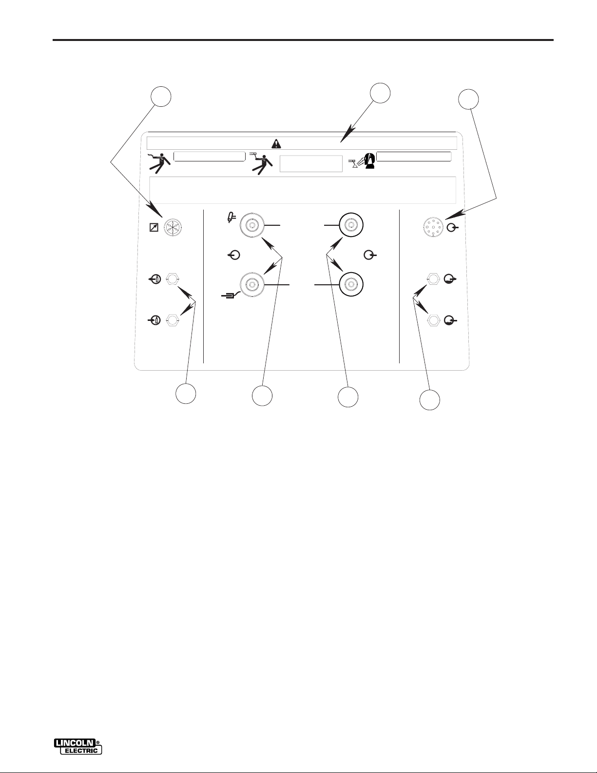
REAR CONNECTIONS
7
WARNING
ELECTRODE
WORK
1
2
V
6
5
FIGURE 8
1 WARNING INFORMATION - Important information
regarding the safe installation, operation, and
servicing of the TIG Module.
2 INPUT RECEPTACLE - For connecting the
Control Cable from the power source. This
receptacle contains the following circuits: Input
power, power source contactor control (where
applicable) and power source remote control
(where applicable). This is a 9-pin receptacle.
3 WATER VALVE FITTINGS (OPTIONAL) - Water
valve inlet and outlet fittings, 5/8-18 left-hand
threads. For connection of cooling water to and
from the TIG torch. Supplied as part of the optional
K844-1 Water Valve Kit.
44
4 POWER INPUT CONNECTIONS - Connections for
the work (bottom) and electrode (top) cables from
the Ranger power source. 1/2-13 threaded stud
connections.
5 POWER OUTPUT CONNECTIONS - Connections
for the work lead (bottom) and TIG torch (top). 1/213 threaded stud connections.
6 GAS VALVE FITTINGS - Gas valve inlet and outlet
fittings, 5/8-18 right hand threads. For connection
of the shielding gas supply and the TIG torch gas
fitting.
7 ARC START SWITCH / AMPTROL RECEPTACLE -
6-socket receptacle for connecting an arc start
switch or an Amptrol remote current control.
3
– 22 –
TIG MODULE
Page 34

OPERATION
RANGER 8 OPERATION
The tables (Table 8 & 9) list the recommended switch
and control settings for the TIG Module/Ranger 8
combination. The first table is for the Ranger 8, and
the second for the Ranger 8 with the K892-1 Remote
Kit installed.
Operate the Ranger 8 in accordance with the Ranger
8 Manual.
TABLE 8: K930-[ ] / RANGER 8 (WITHOUT THE K892-1) SETTINGS
K930-[ ] SETTINGS
HF
HIGH
POWER
FREQUENCY
AFTERFLOW
Note: For AC TIG welding, the maximum TIG welding
output currents on each range setting will be
approximately 50% higher that those marked
on the nameplate. This is due to the special
nature of the AC TIG welding arc. Do not AC
TIG weld on the 225AC range setting. The
output current may exceed the rating of the
Ranger 8.
2
A
CURRENT
CONTROL
CURRENT
CONTROL
SWITCH
ON
IDLER
SWITCH
HIGH
ADJUST
TO SUIT,
5 - 55 SECONDS
START
- OR -
CONTINUOUS
SETTING HAS
NO EFFECT
ON OUTPUT SETTING HAS
RANGER 8 (WITHOUT THE K892-1 REMOTE KIT) SETTINGS
RANGE CONTROL
STICK/TIG
POLARITY
SELECT TO SUIT,
DC-
AC
50 - 210
DESIRED OUTPUT
SELECT TO SUIT,
50-175
NO EFFECT
ON OUTPUT
SET FOR
CURRENT
TIG MODULE
– 23 –
Page 35

OPERATION
TABLE 9: K930-[ ] / RANGER 8 (WITH THE K892-1) SETTINGS
K930-[ ] SETTINGS
A
CURRENT
CONTROL
ADJUST
TO SUIT
0-10
POWER
ON
HF
HIGH
FREQUENCY
START
- OR -
CONTINUOUS
2
AFTERFLOW
ADJUST
TO SUIT,
5 - 55 SECONDS
RANGER 8 (WITH THE K892-1 REMOTE KIT INSTALLED) SETTINGS
RANGE
IDLER
SWITCH
CURRENT
CONTROL
SWITCH
REMOTE (WITH
AN AMPTROL)
LOCAL (WITH AN
ARC START
SWITCH)
CONTROL AT
WELDER / REMOTE
CONTROL
STICK/TIG
POLARITY
DC-
HIGH
AC
If your Ranger 8 has the optional K892-1 Remote
Receptacle installed, refer to Figure 9, which covers
the proper use of the TIG Module Current Control, Arc
Start Switch, and Amptrols.
Once the TIG Module and Ranger 8 are properly set
up, TIG welding is very easy. Position the torch in
place, lower your helmet, and press the Arc Start
Switch or Amptrol. The power source contactor (or
the optional TIG Module contactor) will close, gas will
flow for a one-half second preflow time, and the high
frequency will come on. The arc should strike and
SELECT TO SUIT,
50 - 210
SELECT TO SUIT,
50-175 REMOTE CONTROL
welding should begin. At the end of the weld, simply
release the Arc Start Switch or Amptrol, and the
contactor will open, shutting off the arc. The Afterflow
time will begin, cooling the torch, protecting the weld
and the tungsten.
If another weld is started during the Afterflow time,
there will be no preflow time delay. The contactor will
close and the high frequency will come on
immediately when the Arc Start Switch or Amptrol is
pressed.
– 24 –
TIG MODULE
Page 36
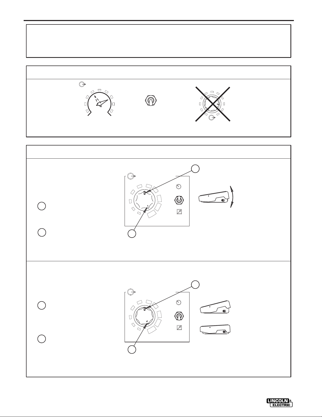
OPERATION
USE OF THE CURRENT LIMIT CONTROL,
ARC START SWITCH, AND AMPTROL ON WELDERS
EQUIPPED WITH REMOTE CONTROL CAPABILITY.
WELDER SETTINGS
RANGE
90
120
160
250
EXAMPLE 1:
45
LOW
MED
HIGH
CHOOSE THE
RANGE SETTING.
(IF APPROPRIATE)
AN ARC START SWITCH
OR AN AMPTROL IS USED TO START THE
ARC. THE CURRENT CONTROL SETS THE
WELDING CURRENT.
A
HALF THE RANGER SETTING IS
AVAILABLE BECAUSE THE CURRENT CONTROL
IS SET TO THE HALF-WAY POINT.
B
FULL OUTPUT IS AVAILABLE BECAUSE
THE CURRENT CONTROL IS SET TO MAXIMUM.
OUTPUT CONTROL
AT WELDER
200
OUTPUT CONTROL
REMOTE
CHOOSE REMOTE
OUTPUT CONTROL.
TIG MODULE SETTINGS
A
CURRENT CONTROL
6
5
4
3
2
1
B
7
10
LOCAL
8
9
REMOTE
5
6
4
3
2
1
0
7
8
9
10
OUTPUT
THE OUTPUT DIAL HAS
NO EFFECT ON THE OUTPUT.
A
AMPTROL POSITION HAS
NO EFFECT ON THE
OUTPUT CURRENT.
EXAMPLE 2:
AN AMPTROL IS USED FOR
REMOTE CURRENT CONTROL. THE CURRENT
CONTROL SETS THE MAXIMUM AVAILABLE
WELDING CURRENT.
A
THE CURRENT CAN BE VARIED FROM
MINIMUM TO HALF OF THE RANGER SETTING
BECAUSE THE CURRENT CONTROL IS SET TO
THE HALF-WAY POINT.
B
THE CURRENT CAN BE VARIED FROM
MINIMUM TO MAXIMUM OF THE RANGER
SETTING BECAUSE THE CURRENT CONTROL
KNOB IS SET TO MAXIMUM.
TIG MODULE
A
CURRENT CONTROL
5
4
3
2
1
B
FIGURE 9
6
7
10
– 25 –
A
LIGHT PRESSURE -
LOCAL
8
9
REMOTE
LOW OUTPUT CURRENT
HEAVY PRESSURE -
UP TO THE SETTING
OF THE CURRENT.
CONTROL.
Page 37
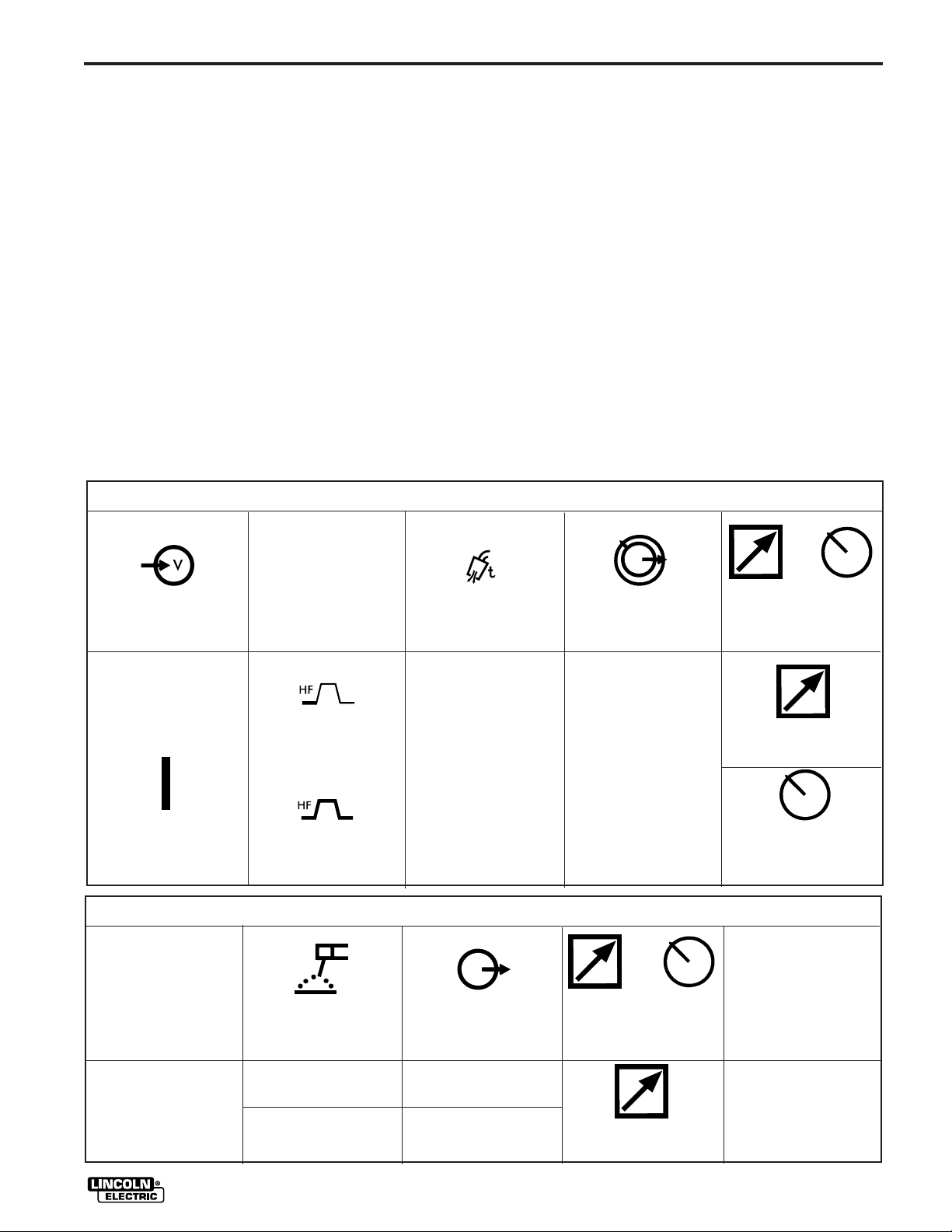
OPERATION
RANGER 9 OPERATION
The table (Table 10) lists the recommended switch
and control settings for the TIG Module/Ranger 9
combination.
Operate the Ranger 9 in accordance with the Ranger
9 Manual.
Note that for AC TIG welding, the maximum TIG
welding output currents on each range setting will be
approximately 50% higher that those marked on the
nameplate. This is due to the special nature of the
AC TIG welding arc. Do not AC TIG weld on the 200
or 250 amp range settings. The output current may
exceed the rating of the Ranger 9.
Because your Ranger 9 has remote control capability,
refer to Figure 9, which covers the proper use of the
TABLE 10: K930-[ ] / RANGER 9 SETTINGS
K930-[ ] SETTINGS
TIG Module Current Control, Arc Start Switch, and
Amptrols.
Once the TIG Module and Ranger 9 are properly set
up, TIG welding is very easy. Position the torch in
place, lower your helmet, and press the Arc Start
Switch or Amptrol. The Ranger 9’s output contactor
will close, the engine will go to high idle, gas will flow,
and after a one-half second preflow time, the high
frequency will come on. The arc should strike and
welding should begin. At the end of the weld, simply
release the Arc Start Switch or Amptrol, and the
contactor will open, shutting off the arc. The Afterflow
time will begin, cooling the torch, protecting the weld
and the tungsten.
If another weld is started during the Afterflow time,
there will be no preflow time delay. The contactor will
close and the high frequency will come on
immediately when the Arc Start Switch or Amptrol is
pressed.
POWER
ON
IDLER
SWITCH
AUTO
HF
HIGH
FREQUENCY
START
- OR -
CONTINUOUS
RANGER 9 SETTINGS
STICK/TIG
POLARITY RANGE
DC-
AC
AFTERFLOW
ADJUST
TO SUIT,
5 - 55 SECONDS
SELECT TO SUIT,
45 - 250
SELECT TO SUIT,
45-160
2
A
CURRENT
CONTROL
ADJUST
TO SUIT
0-10
CONTROL AT
WELDER / REMOTE
CONTROL
REMOTE
CONTROL
CURRENT
CONTROL
SWITCH
REMOTE (WITH
AN AMPTROL)
LOCAL (WITH AN
ARC START
SWITCH)
WELDING TERMINALS
ALWAYS
ON / REMOTELY
CONTROLLED
REMOTELY
CONTROLLED
– 26 –
TIG MODULE
Page 38
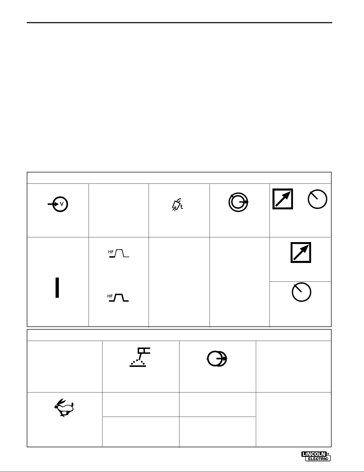
OPERATION
RANGER 10 / RANGER 300 D OPERATION
The table (Table 11) lists the recommended switch and control settings
for the TIG Module/Ranger 10 or TIG Module/Ranger 300 D
combination. Make sure all connections are tight before proceeding.
Operate the Ranger 10 or Ranger 300 D in accordance with
the proper Operator’s Manual.
Note that for AC TIG welding, the maximum TIG welding output
currents on each range setting will be approximately 50%
higher that those marked on the nameplate. This is due to the
special nature of the AC TIG welding arc. Do not AC TIG weld
on the 200 or 250 amp range settings. The output current may
exceed the rating of the Ranger 10 or Ranger 300 D.
Because your Ranger 10 / Ranger 300 D has remote control
capability, refer to the diagram Figure 9 which covers the
proper use of the Tig Module Current Control, Arc Start
Switches, and Amptrols.
Once the TIG Module and Ranger 10 or Ranger 300 D are
properly set up, TIG welding is very easy. Position the torch
in place, lower your helmet, and press the Arc Start Switch
or Amptrol. The TIG Module’s optional contactor will close,
gas will flow for a one-half second preflow time, and the high
frequency will come on. The arc should strike and welding
should begin. At the end of the weld, simply release the Arc
Start Switch or Amptrol, and the contactor will open, shutting
off the arc. The Afterflow time will begin, cooling the torch,
protecting the weld and the tungsten.
If another weld is started during the Afterflow time, there will
be no preflow time delay. The contactor will close and the
high frequency will come on immediately when the Arc Start
Switch or Amptrol is pressed.
TABLE 11: K930-[ ] / RANGER 10 or RANGER 300 D SETTINGS
K930-[ ] SETTINGS
POWER
ON
IDLER
SWITCH
HIGH
HF
HIGH
FREQUENCY
START
- OR -
CONTINUOUS
STICK/TIG
POLARITY
2
AFTERFLOW
ADJUST
TO SUIT,
5 - 55 SECONDS
RANGER 10 SETTINGS
RANGE
SELECT TO SUIT,
DC-
AC
45 - 250
SELECT TO SUIT,
45-160
A
CURRENT
CONTROL
ADJUST
TO SUIT
0-10
CURRENT
CONTROL
SWITCH
REMOTE (WITH
AN AMPTROL)
LOCAL (WITH AN
ARC START
SWITCH)
OUTPUT
CONTROL
SWITCH
OUTPUT
CONTROL
REMOTE
TIG MODULE
– 27 –
Page 39
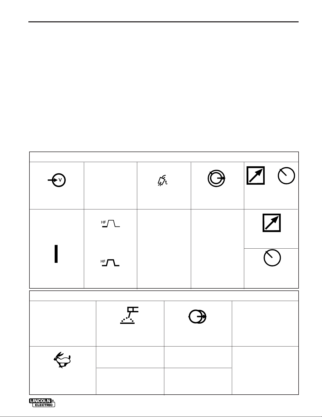
OPERATION
RANGER 10-LX / RANGER 300 DLX OPERATION
The table (Table 12) lists the recommended switch and control settings
for the TIG Module/Ranger 10-LX or TIG Module/Ranger 300 DLX
combination. Make sure all connections are tight before proceeding.
Operate the Ranger 10-LX or Ranger 300 DLX in
accordance with the proper Operator’s Manual.
Note that for AC TIG welding, the maximum TIG welding output currents
on each range setting will be approximately 50% higher that those
marked on the nameplate. This is due to the special nature of the AC
TIG welding arc. Do not AC TIG weld on the 200 or 250 amp range
settings. The output current may exceed the rating of the Ranger 10-LX
or Ranger 300 DLX.
Because your Ranger 10-LX or Ranger 300 DLX has
remote control capability, refer to the diagram Figure 9
which covers the proper use of the TIG Module Current
Control, Arc Start Switches, and Amptrols.
Once the TIG Module and Ranger 10-LX or Ranger 300 DLX
are properly set up, TIG welding is very easy. Position the torch
in place, lower your helmet, and press the Arc Start Switch or
Amptrol. The TIG Module’s optional contactor will close, gas
will flow for a one-half second preflow time, and the high
frequency will come on. The arc should strike and welding
should begin. At the end of the weld, simply release the Arc
Start Switch or Amptrol, and the contactor will open, shutting off
the arc. The Afterflow time will begin, cooling the torch,
protecting the weld and the tungsten.
If another weld is started during the Afterflow time, there will
be no preflow time delay. The contactor will close and the
high frequency will come on immediately when the Arc Start
Switch or Amptrol is pressed.
TABLE 12: K930-[ ] / RANGER 10-LX or RANGER 300 DLX SETTINGS
K930-[ ] SETTINGS
A
CURRENT
CONTROL
POWER
HF
HIGH
FREQUENCY
2
AFTERFLOW
CURRENT
CONTROL
SWITCH
ON
IDLER
SWITCH
HIGH
START
- OR -
CONTINUOUS
RANGER 10-LX SETTINGS
STICK/TIG
POLARITY
DC-
AC
ADJUST
TO SUIT,
5 - 55 SECONDS
SELECT TO SUIT,
SELECT TO SUIT,
ADJUST
TO SUIT
0-10
REMOTE (WITH
AN AMPTROL)
LOCAL (WITH AN
ARC START
SWITCH)
RANGE
OUTPUT
CONTROL
SWITCH
45 - 250
OUTPUT
CONTROL
REMOTE
45-160
– 28 –
TIG MODULE
Page 40

OPERATION
OPERATION ON OTHER LINCOLN
POWER SOURCES
The table (Table 13) lists the recommended switch
and control settings for the TIG Module when used
with various Lincoln power sources.
Operate the power source in accordance with its
Manual.
Note that AC power sources must be derated
approximately 50% when used for AC TIG welding.
This is due to the special nature of the TIG welding
arc. Input currents will also be higher when AC TIG
welding. Be sure the power source is properly fused
to handle this situation.
If your power source has remote control capability,
TABLE 13: K930-[ ] / LINCOLN POWER SOURCE SETTINGS
K930-[ ] SETTINGS
refer to the second half of the diagram Figure 9 which
covers the proper use of the TIG Module Current
Control with Hand and Foot Amptrols.
Once the TIG Module and the power source are
properly set up, TIG welding is very easy. Position
the torch in place, lower your helmet, and press the
Arc Start Switch or Amptrol. The power source
contactor (or the optional TIG Module contactor) will
close, gas will flow for a one-half second preflow time,
and the high frequency will come on. The arc should
strike and welding should begin. At the end of the
weld, simply release the Arc Start Switch or Amptrol,
and the contactor will open, shutting off the arc. The
Afterflow time will begin, cooling the torch, protecting
the weld and the tungsten. If another weld is started
during the Afterflow time, there will be no preflow time
delay. The contactor will close immediately when the
Arc Start Switch or Amptrol is pressed.
POWER
ON
WELD MODE
POLARITY
CHOOSE CONSTANT
CURRENT (STICK)
OUTPUT, AC OR
DC AS REQUIRED
HF
HIGH
FREQUENCY
START
- OR -
CONTINUOUS
AFTERFLOW
5 - 55 SECONDS
2
ADJUST
TO SUIT,
LINCOLN POWER SOURCE SETTINGS
CURRENT
OUTPUT
CONTROL
IF POWER SOURCE HAS REMOTE
CONTROL CAPABILITY, THIS
CONTROL WILL HAVE NO EFFECT
FOR OTHER POWER SOURCES,
SET TO OUTPUT CURRENT
DESIRED
THIS SWITCH APPEARS
CONTROL
SWITCH
SET TO REMOTE IF
ON THE POWER
SOURCE
A
CURRENT
CONTROL
ADJUST
TO SUIT
0-10
CURRENT
CONTROL
SWITCH
REMOTE (WITH
AN AMPTROL)
LOCAL (WITH AN
ARC START
SWITCH)
CONSULT YOUR
POWER SOURCE
INSTRUCTION OR
OPERATOR’S MANUAL
FOR COMPLETE
INFORMATION
TIG MODULE
– 29 –
Page 41

TIG WELDING INFORMATION
TYPICAL CURRENT RANGES
Unbalanced Wave Balanced Wave
Pure
Tungsten
2-15
5-15
10-60
Tungsten
Electrode
Diameter
in. (mm)
.010 (.25)
0.020 (.50)
0.040 (1.0)
DCEN (-) DCEP ( +)
1%, 2%
Thoriated
Tungsten
2-15
5-20
15-80
1%, 2%
Thoriated
Tungsten
(3)
(3)
(3)
OPERATION
TABLE 14
(1)
FOR TUNGSTEN ELECTRODES
AC Approximate Argon
1%, 2%
Thoriated
Tungsten
Zirconiated
2-15
5-20
15-80
Pure
Tungsten
2-15
10-20
20-30
Gas Flow Rate
C.F.H. (1/min.)
1%, 2%
Thoriated
Tungsten
Zirconiated Aluminum
---
5-20
20-60
3-8 (2-4)
5-10 (3-5)
5-10 (3-5)
(2)
Stainless
3-8 (2-4)
5-10 (3-5)
5-10 (3-5)
Steel
TIG Torch
Nozzle
(4),(5)
Size
#4, #5, #6
1/16 (1.6)
3/32 (2.4)
1/8 (3.2)
5/32 (4.0)
3/16 (4.8)
1/4 (6.4)
(1) When used with argon gas. The current ranges shown must be reduced when using argon/helium or pure helium shielding gasses.
(2) Tungsten electrodes are classified as follows by the American Welding Society (AWS):
Pure . . . . . . . . . . . . . . . EWP
1% Thoriated . . . . . . . . EWTh-1
2% Thoriated . . . . . . . . EWTh-2
Though not yet recognized by the AWS, Ceriated Tungsten is now widely accepted as a substitute for 2% Thoriated Tungsten in AC and DC applications.
(3) DCEP is not commonly used in these sizes.
(4) TIG torch nozzle “sizes” are in multiples of 1/16ths of an inch:
#10 = 5/8 in. (16 mm)
(5) TIG torch nozzles are typically made from alumina ceramic. Special applications may require lava nozzles, which are less prone to breakage, but cannot
withstand high temperatures and high duty cycles.
70-150
150-250
250-400
400-500
500-750
750-1000
#4 = 1/4 in. (6 mm)
#5 = 5/16 in. (8 mm)
#6 = 3/8 in. (10 mm)
#7 = 7/16 in. (11 mm)
#8 = 1/2 in. (12.5 mm)
10-20
15-30
25-40
40-55
55-80
80-125
50-100
100-160
150-210
200-275
250-350
325-450
70-150
140-235
225-325
300-400
400-500
500-630
30-80
60-130
100-180
100-240
190-300
250-400
60-120
100-180
160-250
200-320
290-390
340-525
5-10 (3-5)
13-17 (6-8)
15-23 (7-11)
21-25 (10-12)
23-27 (11-13)
28-32 (13-15)
9-13 (4-6)
11-15 (5-7)
11-15 (5-7)
13-17 (6-8)
18-22 (8-10)
23-27(11-13)
#5, #6
#6, #7, #8
#8, #10
– 30 –
TIG MODULE
Page 42

ACCESSORIES
OPTIONS / ACCESSORIES
The following field installed Kits and accessories may
be used dependingon the application:
K936 Control Cables
At least one of the following control cables is
needed to connect the TIG Module to the power
source. Four different cables are available. The
proper choice of cable depends on the power
source being used. See the installation section to
choose the proper control cable. The control
cable carries one or more of the following circuits
between the TIG Module and the power source:
Input power, remote control signals, contactor
control signals, and ground.
K844-1 Water Valve Kit
A field installed kit which contains one water valve for
mounting inside the TIG Module. The water valve is
controlled by the same preflow and afterflow timers as
the gas valve.
Other Compatible Lincoln Accessories:
K963 Hand Amptrol
K870 Foot Amptrol
K814 Arc Start Switch
All Magnum TIG torches and accessories
Compatible Equipment
K936-1 9-Socket (at the TIG Module) to 14-pin
(at the power source) (Contains circuits
2, 4, 31, 32, 75, 76, 77 and ground)
K936-3 9-Socket to a grounded 115V plug and a
6-pin MS-connector (Contains circuits
31, 32, 75, 76, 77 and ground)
K936-4 9-Socket to a grounded 115V plug
(Contains circuits 31, 32 and ground.)
K937 Control Cables Extensions
Control cable extensions are available in 22 and
45 foot engths. These allow the TIG Module to be
operated at distances up to 200 feet from the
power source. The extensions connect between
the standard control cable and the TIG Module.
K937-22 22 foot extension cable, 9-Socket to 9-pin
K937-45 45 foot extension cable, 9-Socket to 9-pin
K938-1 Contactor Kit
This field installed kit must be installed in the TIG
Module whenever it is used with a power source
which does not have a built-in contactor for constant
current (stick/TIG) welding. See the list of compatible
power sources to see which applications require the
Contactor Kit.
The TIG Module can be used with the following
Lincoln power sources:
Ranger 8
1
Ranger 9
Ranger 10
Ranger 10-LX
1
1
DC-250
DC-400
DC-600
DC-650Pro/DC-750
R3R-300/400/500,
including “I” versions
Idealarc 250 AC/DC
Weldanpower 150
Weldanpower 150 AC/DC
Weldanpower G8000
SA 250 Perkins
SAE 350 Deutz
SAE 400
Classic I
Classic II
1
1,2
1
Classic III & IIID
1
Requires the K938-1 Contactor Kit in the TIG Module
2
Requires a source of 115VAC power
1
1
1
1
1
1
1
1
For installation of field installed accessories see the
INSTALLATION SECTION.
K939-1 Docking Kit
The Docking Kit provides a means to “dock” the TIG
Module on top of a flat-roofed power source, or any
other flat surface measuring at least 10 X 15 inches
(255 X 381 mm). It includes a latch and provisions for
a user-supplied padlock to lock the TIG Module in
place.
TIG MODULE
– 31 –
Page 43

MAINTENANCE
SAFETY PRECAUTIONS
WARNING
ELECTRIC SHOCK can kill.
• Only qualified personnel should
perform this maintenance.
• Turn the input power OFF at the
disconnect switch or fuse box
before working on this
equipment.
• Do not touch electrically hot
parts.
WARNING
To avoid receiving a high frequency shock, keep the
TIG torch and cables in good condition.
PERIODIC MAINTENANCE
4. If the TIG Module is used in locations where there
are large amounts of conductive metal or salt
particles in the air, it is recommended that the
inside rear assembly of the TIG Module be
cleaned out with clean, dry, low pressure
compressed air on a regular basis (monthly, for
example). To do so, first be sure that the input
power has been removed from the TIG Module.
Remove the case wraparound. This exposes the
spark gap, high voltage transformer, high
frequency transformer, and other components.
Clean this area with compressed air.
Very little maintenance is required to keep your TIG
Module in top operating condition. No specific
schedule can be set for performing the following
items; factors such as hours of usage and the
machine environment should be considered when
establishing a maintenance schedule.
1. Periodically blow off dust and dirt which may
accumulate on the outside of the TIG Module.
2. Inspect the welding and control cables for fraying,
cuts and bare spots.
3. Inspect the spark gap at regular intervals to
maintain the recommended spark gap setting.
Use the following procedure:
The spark gap is set at the factory for a gap of
0.015(.38mm) inches. This setting is proper for
most applications.
To adjust the spark, first be sure that the Ranger
welder is off, and that the input cable is
disconnected from the Input Receptacle on the
back of the TIG Module. Remove the outer case
wraparound, and find the spark gap assembly
located at the top right hand side of the internal
compartment. Check the spark gap setting with a
feeler gauge. If adjustment is required, loosen
one of the Allen head screws which secure the
spark gap electrodes in place. Set the gap, and
tighten the screw. Reinstall the case wraparound.
– 32 –
TIG MODULE
Page 44

TROUBLESHOOTING
How To Use Troubleshooting Guide
WARNING
This Troubleshooting Guide is designed to be used by the machine Owner/Operator. Unauthorized repairs
performed on this equipment may result in danger to the technician and machine operator and will invalidate your
factory warranty. For your safety, please observe all safety notes and precautions detailed in the Safety Section of
this manual to avoid electrical shock or danger while troubleshooting this equipment.
___________________________________________________________________________________________
This Troubleshooting Guide is provided to help you
locate and correct possible machine misadjustments.
Simply follow the three-step procedure listed below.
Step 1. LOCATE PROBLEM (SYMPTOM)
Look under the column labeled “PROBLEM
(SYMPTOMS)”. This column describes possible
symptoms that your machine may exhibit. Find the
listing that best describes the symptom that your
machine is exhibiting.
Step 2. PERFORM EXTERNAL RECOMMENDED
TESTS
The second column labeled “POSSIBLE AREAS OF
MISADJUSTMENT(S)” lists the obvious external
possibilities that may contribute to the machine
symptom. Perform these tests/checks in the order
listed. In general, these tests can be conducted
without removing the case wrap-around cover.
Step 3. CONSULT LOCAL AUTHORIZED FIELD
SERVICE FACILITY
If you have exhausted all of the recommended tests in
step 2, consult your local Authorized Field Service
Facility.
CAUTION
If for any reason you do not understand the test procedures or are unable to perform the tests/repairs safely,
contact your local Authorized Field Service Facility for technical troubleshooting assistance before you proceed.
TIG MODULE
– 33 –
Page 45

TROUBLESHOOTING
Troubleshooting Guide
PROBLEMS
(SYMPTOMS)
Major Physical or Electrical
Damage is Evident.
High frequency “jumps” from the
electrode to work but welding arc
does not establish
POSSIBLE
CAUSE
OUTPUT PROBLEMS
1. Contact your local Lincoln
Authorized Field Service
Facility
1. Make certain that the welder
power source has weld outputCheck for open circuit voltage
at welding power source
Observe Safety Guidelines
detailed in the beginning of this manual.
RECOMMENDED
COURSE OF ACTION
If all recommended possible areas
of misadjustment have been
checked and the problem persists,
Contact your local Lincoln
Authorized Field Service Facility.
2. Make certain that the tungsten
type and size is correct for the
process
3. The tungsten may be
contaminated - clean or replace
CAUTION
If for any reason you do not understand the test procedures or are unable to perform the tests/repairs safely,
contact your local Authorized Field Service Facility for technical troubleshooting assistance before you proceed.
– 34 –
TIG MODULE
Page 46

TROUBLESHOOTING
Observe Safety Guidelines
detailed in the beginning of this manual.
PROBLEMS
(SYMPTOMS)
No weld output, no gas flow and no
high frequency at spark gap
Low weld output current when
operating in remote control
POSSIBLE
CAUSE
OUTPUT PROBLEMS
1. Check arc start switch or
remote control unit
2. Make certain both the TIG
Module and the welding power
source are powered up
1. Make certain the welder power
source is in the remote control
mode
Troubleshooting Guide
RECOMMENDED
COURSE OF ACTION
If all recommended possible areas
of misadjustment have been
checked and the problem persists,
Contact your local Lincoln
Authorized Field Service Facility.
2. The current control (R4) may
be set too low for the process
CAUTION
If for any reason you do not understand the test procedures or are unable to perform the tests/repairs safely,
contact your local Authorized Field Service Facility for technical troubleshooting assistance before you proceed.
TIG MODULE
– 35 –
Page 47

Troubleshooting Guide
TROUBLESHOOTING
Observe Safety Guidelines
detailed in the beginning of this manual.
PROBLEMS
(SYMPTOMS)
High frequency not present or
intermittent at torch electrode
High frequency not present at spark
gap
POSSIBLE
CAUSE
HIGH FREQUENCY PROBLEMS
1. Check for correct gas and gas
flow
2. Check torch and work cables
for breaks and leaks
3. Check spark gap for correct
setting 0.015in. (.25mm)
1. Make certain that the High
Frequency switch (S2) is NOT
in the OFF position
2. Check spark gap for correct
setting 0.015in (.25mm)
iRECOMMENDED
COURSE OF ACTION
If all recommended possible areas
of misadjustment have been
checked and the problem persists,
Contact your local Lincoln
Authorized Field Service Facility.
High Frequency stays on after the
arc is established
1. High frequency switch (S2) is in
the continuous position
CAUTION
If for any reason you do not understand the test procedures or are unable to perform the tests/repairs safely,
contact your local Authorized Field Service Facility for technical troubleshooting assistance before you proceed.
– 36 –
TIG MODULE
Page 48
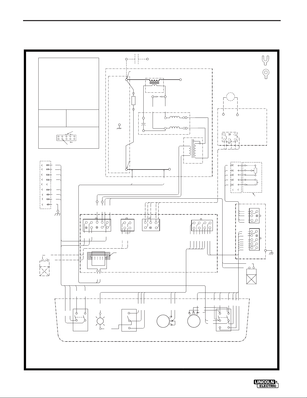
WIRING DIAGRAM FOR CODES 10135, 10203 and 10284
HIGH VOLTAGE CAPACITOR .0025/10KV
C1
CR1
OPTIONAL CONTACTOR
L1,L2
HI-FREQ. INDUCTOR
PILOT LIGHT
PL1
BLEEDER RESISTOR 150/100W
R2
R3
AFTERFLOW TIME POTENTIOMETER 500K/2W
CURRENT CONTROL POTENTIOMETER 10K/2W
R4
POWER SWITCH
S1
S2
HIGH FREQUENCY SWITCH
S5
CURRENT CONTROL SWITCH
GAS SOLENOID VALVE
SV1
OPTIONAL WATER SOLENOID VALVE
SV2
HIGH VOLTAGE TRANSFORMER
T1
HIGH FREQUENCY TRANSFORMER
T2
LEAD COLORING CODE:
B- BLACK
G- GREEN
N- BROWN
R- RED
U- BLUE
W- WHITE
CONNECTOR PIN NUMBERS:
INPUT
RECEPTACLE
2
A
B
4
31
C
32
D
E
75
F
76
G
H
77
I
403
404
10
5
G
COMPONENT VALUE UNITS:
CAPACITOR: MFD/VOLTS
RESISTOR: OHMS/WATTS
ELECTRICAL SYMBOLS PER
EXAMPLE: THIS PIN IN
CONNECTOR J1 IS "4J1"
LATCH
6
1
E1537
232
231
WIRING DIAGRAM
TIG MODULE
FROM POWER SOURCE
ELECTRODE TERMINAL
IF OPTIONAL CONTACTOR
IS CONNECTED
CR1
FROM POWER SOURCE
ELECTRODE TERMINAL
TO TIG TORCH
T2
CR1
CONTACTOR
BYPASS/
STABILIZER
BOARD
C1
SPARK
GAP
*
314
315
*
L2
R2
L1
S
SEC
PRI
F
FROM POWER SOURCE
WORK TERMINAL
311A
301
308
307
302
404
J2
403
CONTROL BOARD
J1
4
2
CURRENT SENSOR
TO WORK
311B
J3
T1
REAR
ASSEMBLY
NOTE: 1J3 CONNECTS TO 1J5,
2J3 CONNECTS TO 2J5, ETC.
208
206
209
207
210
205
204
202
J4
REMOTE
RECEPTACLE
*
*
A
A
B
B
C
C
D
D
E
E
F
OPTIONAL REMOTE AMPTROL
AND ARC START SWITCH
314 LUG =
315 LUG =
OPTIONAL
CONTACTOR
J5
J22
D
E
C
B
A
J23
75A
274
275
76A
202
277
276
77A
204
PROTECTION
BOARD
302
301
BOARD
10K A-B
AT MINIMUM
TM
SV2
OPTIONAL
WATER
SOLENOID
VALVE
TIG MODULE
232
231
31
ON
OFF
S1
POWER
32
311B
311A
210
-
R
+
PL1
PILOT LIGHT
CONTINUOUS
START
ONLY
206A
OFF
HIGH FREQUENCY
( TILTED DOWN AND VIEWED FROM BACK )
205
S2
CONTROL PANEL
206
207
– 37 –
R3
AFTERFLOW
209
208
CURRENT CONTROL
R4
77A
277A
274A
77
75A
274
LOCAL
75
76
REMOTE
S5
CURRENT CONTROL
SWITCH
277
76A
276
SV1
GAS SOLENOID
275
VALVE
4-19-96D
L9580
NOTE: This diagram is for reference only. It may not be accurate for all machines covered by this manual. The specific diagram for a particular code is pasted inside
the machine on one of the enclosure panels. If the diagram is illegible, write to the Service Department for a replacement. Give the equipment code number.
Page 49
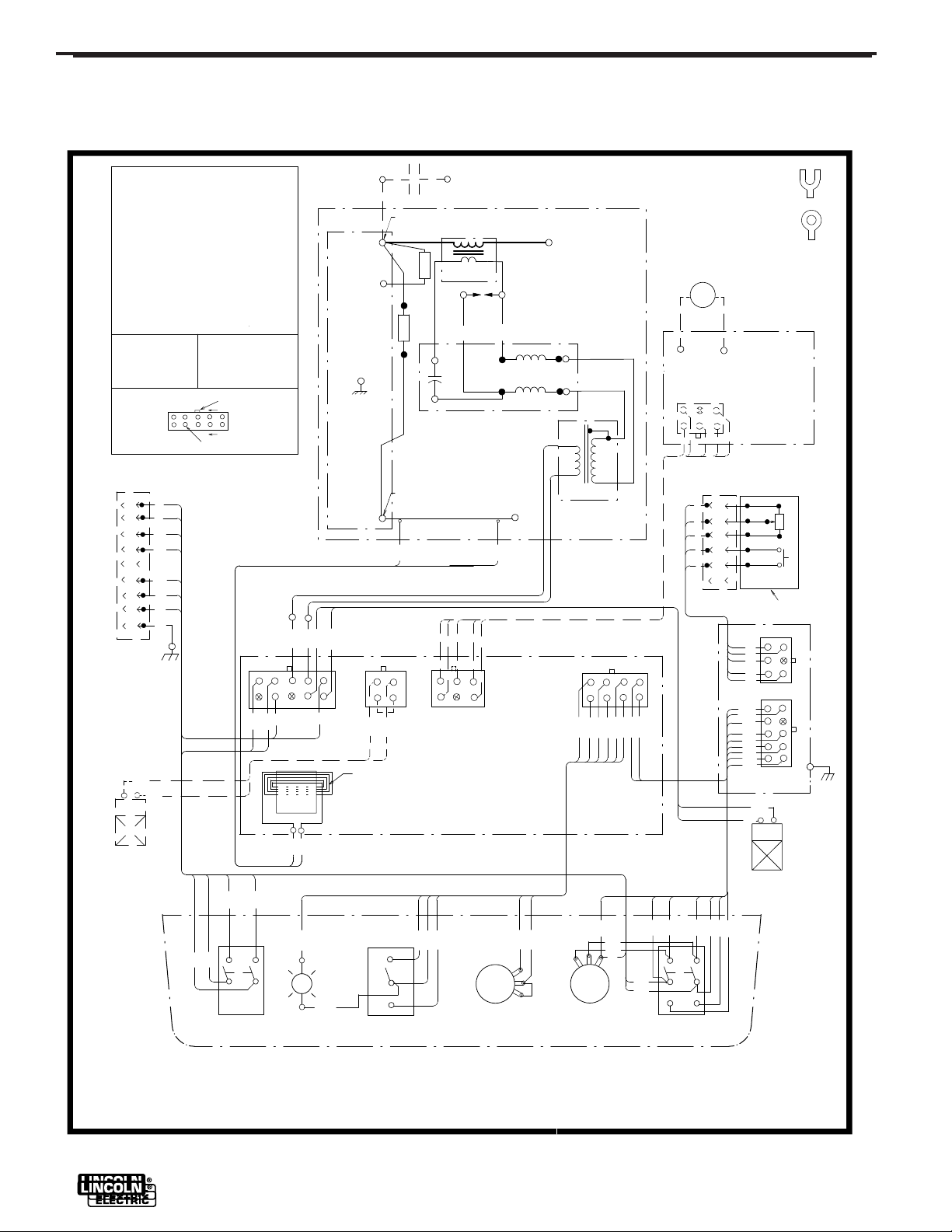
WIRING DIAGRAM
TIG MODULE
WIRING DIAGRAM FOR CODE 11010
V
O
L
T
H
A
G
E
G
H
I
C
1
C
R
1
O
O
C
P
N
O
T
I
A
L
2
L
L
1
,
P
L
1
R
1
R
2
R
3
R
4
S
1
S2
S5
SV1
SV2
T1
T
2
LEAD COLORI NG CODE:
B- BLACK
G- GREEN
N- BROWN
R- RED
U- BLUE
W- WHITE
CONNECTOR PIN NUMBERS:
N
I
RECEPTACLE
A
B
C
D
N
IN
F
R
E
-
Q
U
D
.
I
H
G
H
L
I
T
L
O
T
P
I
B
Y
P
S
R
T
E
O
R
S
I
,
E
S
I
B
L
E
E
D
E
R
R
A
T
I
F
T
E
R
O
F
L
W
C
U
R
C
R
E
O
N
N
T
POWER SWITCH
HIGH FREQUENCY SWITCH
CURRENT CONTROL SWITCH
GAS SOLENOID VALVE
OPTIONAL WATER SOLENOID VALVE
HIGH VOLTAGE TRANSFORMER
HIGH FREQUENCY TRANSFORMER
10
5
P
U
T
2
4
31
32
E
75
F
76
G
H
77
G
I
403
404
0
2
0
5
C
A
T
A
C
C
T
O
A
S
S
T
O
M
P
E
T
R
O
/1
T
O
.
P
A
R
C
I
T
O
R
R
W
1
0
0
1
5
/
S
1
0
0
W
/
0
1
5
R
O
O
T
E
N
T
M
I
E
T
E
P
O
T
O
M
E
L
N
T
I
E
T
COMPONENT VALUE UNITS:
CAPACITOR: MFD/VOLTS
RESISTOR: OHMS/WATTS
ELECTRICAL SYMBOLS PER
E1537
LATCH
6
1
EXAMPLE: THIS PIN IN
CONNECTOR J1 IS "4J1"
0
K
V
FROM POWER SOURCE
ELECTRODE TERMINAL
IF OPTIONAL CONTACTOR
IS CONNECTED
L
U
G
4
=
3
1
*
CR1
F
R
O
M
P
S
O
E
O
R
W
U
R
C
E
C1
E
T
E
R
M
IN
A
L
T
O
G
R
C
I
T
T
H
O
T2
SPARK
GAP
*
314
315
*
L2
CR1
C
O
N
T
A
C
E
L
E
C
T
R
O
D
2
W
5
0
0
K
/
R
2
W
K
1
/
0
E
R
R1
R2
B
P
Y
A
S
S
/
S
L
T
A
B
I
E
R
Z
I
B
O
A
R
D
L1
L
=
U
G
1
5
3
*
T
O
R
O
O
N
P
T
A
I
L
C
O
N
T
A
C
T
O
R
B
O
A
R
D
J5
S
S
E
C
P
R
I
232
231
F
FROM POWER SOURCE
O
T
E
R
W
R
K
M
IN
A
L
311A
301
308
307
302
404
J2
403
1
J
4
2
CURRENT SENSOR
O
W
T
O
311B
3
J
T1
R
K
1
N
O
T
E
:
O
C
J
3
N
2
R
E
A
R
A
S
S
E
M
B
Y
L
C
J
3
O
N
5
,
N
1
J
E
T
O
C
T
S
E
T
C
.
,
J
5
2
N
T
E
O
C
T
S
210
208
206
209
207
205
204
202
CONTROL BOARD
R
E
M
O
T
E
R
E
C
E
P
T
A
C
L
E
A
A
B
B
C
C
D
D
E
E
10K A-B
AT MINIMUM
F
O
R
O
N
E
P
M
T
A
I
L
A
A
S
N
D
R
T
A
R
C
2
2
J
D
E
C
B
4
J
A
2
J
A
7
5
4
2
7
5
2
7
7
6
A
2
2
0
2
7
7
7
6
2
A
7
7
4
2
0
PROTECTION
BOARD
3
0
2
1
3
0
3
TM
O
A
M
P
T
E
T
R
O
L
T
C
H
I
S
W
T
SV2
OPTIONAL
WATER
SOLENOID
VALVE
232
231
31
ON
OFF
S1
POWER
32
311B
311A
210
-
R
+
PL1
PILOT LIGHT
206
205
S2
A
2
0
6
CONTINUOUS
START
ONLY
OFF
HIGH FREQUENCY
CONTROL PANEL
( TILTED DOWN AND VIEWED FROM BACK )
207
– 38 –
R3
AFTERFLOW
209
208
CURRENT CONTROL
R4
77A
277A
274A
SV1
G
S
A
O
S
L
E
N
D
O
I
V
A
V
L
E
277
75A
274
77
75
76
REMOTE
C
U
R
R
E
N
S
W
LOCAL
S5
T
276
76A
275
C
O
N
T
O
R
L
T
C
H
I
A
L12065
NOTE: This diagram is for reference only. It may not be accurate for all machines covered by this manual. The specific diagram for a particular code is pasted inside
the machine on one of the enclosure panels. If the diagram is illegible, write to the Service Department for a replacement. Give the equipment code number.
TIG MODULE
Page 50

NOTES
Page 51

NOTES
Page 52
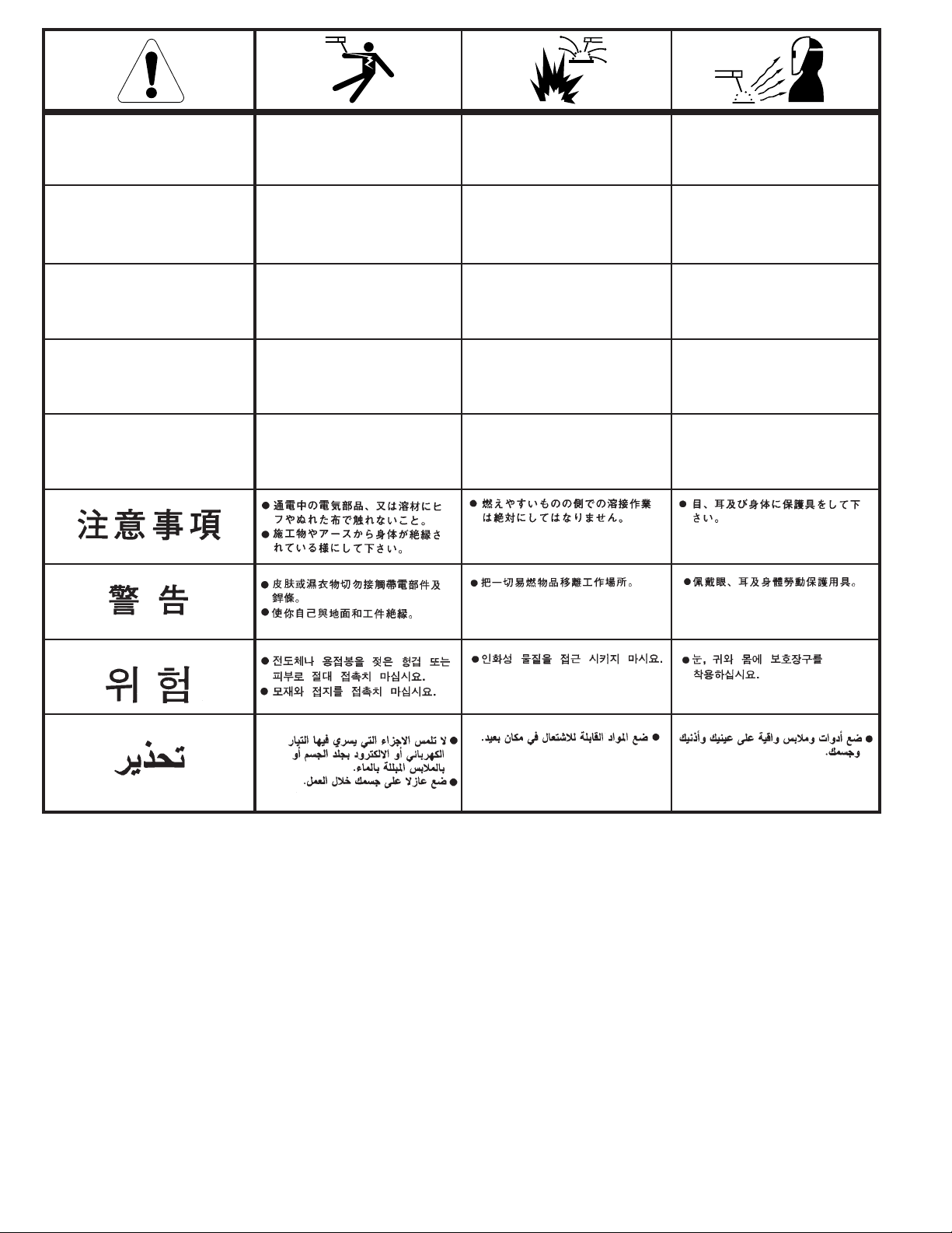
WARNING
Spanish
AVISO DE
PRECAUCION
● Do not touch electrically live parts or
electrode with skin or wet clothing.
● Insulate yourself from work and
ground.
● No toque las partes o los electrodos
bajo carga con la piel o ropa
mojada.
● Aislese del trabajo y de la tierra.
● Keep flammable materials away.
● Mantenga el material combustible
fuera del área de trabajo.
● Wear eye, ear and body protection.
● Protéjase los ojos, los oídos y el
cuerpo.
French
ATTENTION
German
WARNUNG
Portuguese
ATENÇÃO
Japanese
Chinese
Korean
Arabic
● Ne laissez ni la peau ni des
vêtements mouillés entrer en contact
avec des pièces sous tension.
● Isolez-vous du travail et de la terre.
● Berühren Sie keine stromführenden
Teile oder Elektroden mit Ihrem
Körper oder feuchter Kleidung!
● Isolieren Sie sich von den
Elektroden und dem Erdboden!
● Não toque partes elétricas e
electrodos com a pele ou roupa
molhada.
● Isole-se da peça e terra.
● Gardez à l’écart de tout matériel
inflammable.
● Entfernen Sie brennbarres Material!
● Mantenha inflamáveis bem
guardados.
● Protégez vos yeux, vos oreilles et
votre corps.
● Tragen Sie Augen-, Ohren- und Kör-
perschutz!
● Use proteção para a vista, ouvido e
corpo.
READ AND UNDERSTAND THE MANUFACTURER’S INSTRUCTION FOR THIS EQUIPMENT AND THE CONSUMABLES TO BE
USED AND FOLLOW YOUR EMPLOYER’S SAFETY PRACTICES.
SE RECOMIENDA LEER Y ENTENDER LAS INSTRUCCIONES DEL FABRICANTE PARA EL USO DE ESTE EQUIPO Y LOS
CONSUMIBLES QUE VA A UTILIZAR, SIGA LAS MEDIDAS DE SEGURIDAD DE SU SUPERVISOR.
LISEZ ET COMPRENEZ LES INSTRUCTIONS DU FABRICANT EN CE QUI REGARDE CET EQUIPMENT ET LES PRODUITS A
ETRE EMPLOYES ET SUIVEZ LES PROCEDURES DE SECURITE DE VOTRE EMPLOYEUR.
LESEN SIE UND BEFOLGEN SIE DIE BETRIEBSANLEITUNG DER ANLAGE UND DEN ELEKTRODENEINSATZ DES
HERSTELLERS. DIE UNFALLVERHÜTUNGSVORSCHRIFTEN DES ARBEITGEBERS SIND EBENFALLS ZU BEACHTEN.
– 52 –
Page 53

● Keep your head out of fumes.
● Use ventilation or exhaust to
remove fumes from breathing zone.
● Turn power off before servicing.
● Do not operate with panel open or
guards off.
WARNING
● Los humos fuera de la zona de
respiración.
● Mantenga la cabeza fuera de los
humos. Utilice ventilación o
aspiración para gases.
● Gardez la tête à l’écart des fumées.
● Utilisez un ventilateur ou un
aspirateur pour ôter les fumées des
zones de travail.
● Vermeiden Sie das Einatmen von
Schweibrauch!
● Sorgen Sie für gute Be- und
Entlüftung des Arbeitsplatzes!
● Mantenha seu rosto da fumaça.
● Use ventilação e exhaustão para
remover fumo da zona respiratória.
● Desconectar el cable de
alimentación de poder de la
máquina antes de iniciar cualquier
servicio.
● Débranchez le courant avant
l’entretien.
● Strom vor Wartungsarbeiten
abschalten! (Netzstrom völlig
öffnen; Maschine anhalten!)
● Não opere com as tampas removidas.
● Desligue a corrente antes de fazer
serviço.
● Não toque as partes elétricas nuas.
● No operar con panel abierto o
guardas quitadas.
● N’opérez pas avec les panneaux
ouverts ou avec les dispositifs de
protection enlevés.
● Anlage nie ohne Schutzgehäuse
oder Innenschutzverkleidung in
Betrieb setzen!
● Mantenha-se afastado das partes
moventes.
● Não opere com os paineis abertos
ou guardas removidas.
Spanish
AVISO DE
PRECAUCION
French
ATTENTION
German
WARNUNG
Portuguese
ATENÇÃO
Japanese
Chinese
Korean
Arabic
LEIA E COMPREENDA AS INSTRUÇÕES DO FABRICANTE PARA ESTE EQUIPAMENTO E AS PARTES DE USO, E SIGA AS
PRÁTICAS DE SEGURANÇA DO EMPREGADOR.
– 53 –
Page 54

• World's Leader in Welding and Cutting Products •
• Sales and Service through Subsidiaries and Distributors Worldwide •
Cleveland, Ohio 44117-1199 U.S.A. TEL: 216.481.8100 FAX: 216.486.1751 WEB SITE: www.lincolnelectric.com
 Loading...