

Page 1

WIRE FEED MODULE
RETURN TO MAIN MENU
For Wire Feed Module Code Number: 10066, 10914, 11806
Safety Depends on You
Lincoln arc welding and cutting
equipment is designed and built
with safety in mind. However,
your overall safety can be
increased by proper installation
... and thoughtful operation on
your part. DO NOT INSTALL,
OPERATE OR REPAIR THIS
EQUIPMENT WITHOUT READING THIS MANUAL AND THE
SAFETY PRECAUTIONS CONTAINED THROUGHOUT. And,
most importantly, think before
you act and be careful.
™
IM 513-B
February, 2011
OPERATORʼS MANUAL
Copyright © Lincoln Global Inc.
• World's Leader in Welding and Cutting Products •
• Sales and Service through Subsidiaries and Distributors Worldwide •
Cleveland, Ohio 44117-1199 U.S.A. TEL: 216.481.8100 FAX: 216.486.1751 WEB SITE: www.lincolnelectric.com
Page 2
i
SAFETY
i
WARNING
CALIFORNIA PROPOSITION 65 WARNINGS
Diesel engine exhaust and some of its constituents
are known to the State of California to cause cancer, birth defects, and other reproductive harm.
The Above For Diesel Engines
ARC WELDING CAN BE HAZARDOUS. PROTECT YOURSELF AND OTHERS FROM POSSIBLE SERIOUS INJURY OR DEATH.
KEEP CHILDREN AWAY. PACEMAKER WEARERS SHOULD CONSULT WITH THEIR DOCTOR BEFORE OPERATING.
Read and understand the following safety highlights. For additional safety information, it is strongly recommended that you
purchase a copy of “Safety in Welding & Cutting - ANSI Standard Z49.1” from the American Welding Society, P.O. Box
351040, Miami, Florida 33135 or CSA Standard W117.2-1974. A Free copy of “Arc Welding Safety” booklet E205 is available
from the Lincoln Electric Company, 22801 St. Clair Avenue, Cleveland, Ohio 44117-1199.
BE SURE THAT ALL INSTALLATION, OPERATION, MAINTENANCE AND REPAIR PROCEDURES ARE
PERFORMED ONLY BY QUALIFIED INDIVIDUALS.
The engine exhaust from this product contains
chemicals known to the State of California to cause
cancer, birth defects, or other reproductive harm.
The Above For Gasoline Engines
FOR ENGINE
powered equipment.
1.a. Turn the engine off before troubleshooting and maintenance
work unless the maintenance work requires it to be running.
____________________________________________________
1.b. Operate engines in open, well-ventilated
areas or vent the engine exhaust fumes
outdoors.
____________________________________________________
1.c. Do not add the fuel near an open flame
welding arc or when the engine is running.
Stop the engine and allow it to cool before
refueling to prevent spilled fuel from vaporizing on contact with hot engine parts and
igniting. Do not spill fuel when filling tank. If
fuel is spilled, wipe it up and do not start
engine until fumes have been eliminated.
____________________________________________________
1.d. Keep all equipment safety guards, covers and devices in
position and in good repair.Keep hands, hair, clothing and
tools away from V-belts, gears, fans and all other moving
parts when starting, operating or repairing equipment.
____________________________________________________
1.e. In some cases it may be necessary to remove safety
guards to perform required maintenance. Remove
guards only when necessary and replace them when the
maintenance requiring their removal is complete.
Always use the greatest care when working near moving
parts.
___________________________________________________
1.f. Do not put your hands near the engine fan.
Do not attempt to override the governor or
idler by pushing on the throttle control rods
while the engine is running.
1.h. To avoid scalding, do not remove the
radiator pressure cap when the engine is
hot.
ELECTRIC AND
MAGNETIC FIELDS
may be dangerous
2.a. Electric current flowing through any conductor causes
localized Electric and Magnetic Fields (EMF). Welding
current creates EMF fields around welding cables and
welding machines
2.b. EMF fields may interfere with some pacemakers, and
welders having a pacemaker should consult their physician
before welding.
2.c. Exposure to EMF fields in welding may have other health
effects which are now not known.
2.d. All welders should use the following procedures in order to
minimize exposure to EMF fields from the welding circuit:
2.d.1.
Route the electrode and work cables together - Secure
them with tape when possible.
2.d.2. Never coil the electrode lead around your body.
2.d.3. Do not place your body between the electrode and
work cables. If the electrode cable is on your right
side, the work cable should also be on your right side.
___________________________________________________
1.g. To prevent accidentally starting gasoline engines while
turning the engine or welding generator during maintenance
work, disconnect the spark plug wires, distributor cap or
magneto wire as appropriate.
2.d.4. Connect the work cable to the workpiece as close as
possible to the area being welded.
2.d.5. Do not work next to welding power source.
Mar ʻ95
Page 3
ii
SAFETY
ii
ELECTRIC SHOCK can
kill.
3.a. The electrode and work (or ground) circuits
are electrically “hot” when the welder is on.
Do not touch these “hot” parts with your bare
skin or wet clothing. Wear dry, hole-free
gloves to insulate hands.
3.b. Insulate yourself from work and ground using dry insulation.
Make certain the insulation is large enough to cover your full
area of physical contact with work and ground.
In addition to the normal safety precautions, if welding
must be performed under electrically hazardous
conditions (in damp locations or while wearing wet
clothing; on metal structures such as floors, gratings or
scaffolds; when in cramped positions such as sitting,
kneeling or lying, if there is a high risk of unavoidable or
accidental contact with the workpiece or ground) use
the following equipment:
• Semiautomatic DC Constant Voltage (Wire) Welder.
• DC Manual (Stick) Welder.
• AC Welder with Reduced Voltage Control.
3.c. In semiautomatic or automatic wire welding, the electrode,
electrode reel, welding head, nozzle or semiautomatic
welding gun are also electrically “hot”.
3.d. Always be sure the work cable makes a good electrical
connection with the metal being welded. The connection
should be as close as possible to the area being welded.
3.e. Ground the work or metal to be welded to a good electrical
(earth) ground.
3.f.
Maintain the electrode holder, work clamp, welding cable and
welding machine in good, safe operating condition. Replace
damaged insulation.
3.g. Never dip the electrode in water for cooling.
3.h. Never simultaneously touch electrically “hot” parts of
electrode holders connected to two welders because voltage
between the two can be the total of the open circuit voltage
of both welders.
3.i. When working above floor level, use a safety belt to protect
yourself from a fall should you get a shock.
3.j. Also see Items 6.c. and 8.
ARC RAYS can burn.
4.a. Use a shield with the proper filter and cover
plates to protect your eyes from sparks and
the rays of the arc when welding or observing
open arc welding. Headshield and filter lens
should conform to ANSI Z87. I standards.
4.b. Use suitable clothing made from durable flame-resistant
material to protect your skin and that of your helpers from
the arc rays.
4.c. Protect other nearby personnel with suitable, non-flammable
screening and/or warn them not to watch the arc nor expose
themselves to the arc rays or to hot spatter or metal.
FUMES AND GASES
can be dangerous.
5.a. Welding may produce fumes and gases
hazardous to health. Avoid breathing these
fumes and gases. When welding, keep
your head out of the fume. Use enough
ventilation and/or exhaust at the arc to keep
fumes and gases away from the breathing zone. When
welding with electrodes which require special
ventilation such as stainless or hard facing (see
instructions on container or MSDS) or on lead or
cadmium plated steel and other metals or coatings
which produce highly toxic fumes, keep exposure as
low as possible and within applicable OSHA PEL and
ACGIH TLV limits using local exhaust or mechanical
ventilation. In confined spaces or in some circumstances, outdoors, a respirator may be required.
Additional precautions are also required when welding
on galvanized steel.
5. b. The operation of welding fume control equipment is affected
by various factors including proper use and positioning of
the equipment, maintenance of the equipment and the specific welding procedure and application involved. Worker
exposure level should be checked upon installation and
periodically thereafter to be certain it is within applicable
OSHA PEL and ACGIH TLV limits.
5.c.
Do not weld in locations near chlorinated hydrocarbon
coming from degreasing, cleaning or spraying operations.
The heat and rays of the arc can react with solvent vapors
form phosgene, a highly toxic gas, and other irritating products.
5.d. Shielding gases used for arc welding can displace air and
cause injury or death. Always use enough ventilation,
especially in confined areas, to insure breathing air is safe.
vapors
to
5.e. Read and understand the manufacturer’s instructions for this
equipment and the consumables to be used, including the
material safety data sheet (MSDS) and follow your
employer’s safety practices. MSDS forms are available from
your welding distributor or from the manufacturer.
5.f. Also see item 1.b.
Jan ‘09
Page 4
iii
SAFETY
iii
WELDING and CUTTING
SPARKS can
cause fire or explosion.
6.a.
Remove fire hazards from the welding area.
If this is not possible, cover them to prevent
Remember that welding sparks and hot
materials from welding can easily go through small cracks
and openings to adjacent areas. Avoid welding near
hydraulic lines. Have a fire extinguisher readily available.
6.b. Where compressed gases are to be used at the job site,
special precautions should be used to prevent hazardous
situations. Refer to “Safety in Welding and Cutting” (ANSI
Standard Z49.1) and the operating information for the
equipment being used.
6.c. When not welding, make certain no part of the electrode
circuit is touching the work or ground. Accidental contact
can cause overheating and create a fire hazard.
6.d. Do not heat, cut or weld tanks, drums or containers until the
proper steps have been taken to insure that such procedures
will not cause flammable or toxic vapors from substances
inside. They can cause an explosion even
been “cleaned”. For information, purchase “Recommended
Safe Practices for the
Containers and Piping That Have Held Hazardous
Substances”, AWS F4.1 from the American Welding Society
(see address above).
6.e. Vent hollow castings or containers before heating, cutting or
welding. They may explode.
Sparks and spatter are thrown from the welding arc. Wear oil
6.f.
free protective garments such as leather gloves, heavy shirt,
cuffless trousers, high shoes and a cap over your hair. Wear
ear plugs when welding out of position or in confined places.
Always wear safety glasses with side shields when in a
welding area.
6.g. Connect the work cable to the work as close to the welding
area as practical. Work cables connected to the building
framework or other locations away from the welding area
increase the possibility of the welding current passing
through lifting chains, crane cables or other alternate circuits. This can create fire hazards or overheat lifting chains
or cables until they fail.
6.h. Also see item 1.c.
the welding sparks from starting a fire.
though
they have
Preparation
for Welding and Cutting of
CYLINDER may explode
if damaged.
7.a. Use only compressed gas cylinders
containing the correct shielding gas for the
process used and properly operating
regulators designed for the gas and
pressure used. All hoses, fittings, etc. should be suitable for
the application and maintained in good condition.
7.b. Always keep cylinders in an upright position securely
chained to an undercarriage or fixed support.
7.c. Cylinders should be located:
• Away from areas where they may be struck or subjected to
physical damage.
• A safe distance from arc welding or cutting operations and
any other source of heat, sparks, or flame.
7.d. Never allow the electrode, electrode holder or any other
electrically “hot” parts to touch a cylinder.
7.e. Keep your head and face away from the cylinder valve outlet
when opening the cylinder valve.
7.f. Valve protection caps should always be in place and hand
tight except when the cylinder is in use or connected for
use.
7.g. Read and follow the instructions on compressed gas
cylinders, associated equipment, and CGA publication P-l,
“Precautions for Safe Handling of Compressed Gases in
Cylinders,” available from the Compressed Gas Association
1235 Jefferson Davis Highway, Arlington, VA 22202.
FOR ELECTRICALLY
powered equipment.
8.a. Turn off input power using the disconnect
switch at the fuse box before working on
the equipment.
8.b. Install equipment in accordance with the U.S. National
Electrical Code, all local codes and the manufacturer’s
recommendations.
8.c. Ground the equipment in accordance with the U.S. National
Electrical Code and the manufacturer’s recommendations.
6.I. Read and follow NFPA 51B “ Standard for Fire Prevention
During Welding, Cutting and Other Hot Work”, available
from NFPA, 1 Batterymarch Park, PO box 9101, Quincy, Ma
022690-9101.
6.j. Do not use a welding power source for pipe thawing.
Refer to http://www.lincolnelectric.com/safety for additional safety information.
Jan ‘09
Page 5

iv
SAFETY
iv
PRÉCAUTIONS DE SÛRETÉ
Pour votre propre protection lire et observer toutes les instructions
et les précautions de sûreté specifiques qui parraissent dans ce
manuel aussi bien que les précautions de sûreté générales suivantes:
Sûreté Pour Soudage A LʼArc
1. Protegez-vous contre la secousse électrique:
a. Les circuits à lʼélectrode et à la piéce sont sous tension
quand la machine à souder est en marche. Eviter toujours
tout contact entre les parties sous tension et la peau nue
ou les vétements mouillés. Porter des gants secs et sans
trous pour isoler les mains.
b. Faire trés attention de bien sʼisoler de la masse quand on
soude dans des endroits humides, ou sur un plancher
metallique ou des grilles metalliques, principalement dans
les positions assis ou couché pour lesquelles une grande
partie du corps peut être en contact avec la masse.
c. Maintenir le porte-électrode, la pince de masse, le câble
de soudage et la machine à souder en bon et sûr état
defonctionnement.
d.Ne jamais plonger le porte-électrode dans lʼeau pour le
refroidir.
e. Ne jamais toucher simultanément les parties sous tension
des porte-électrodes connectés à deux machines à souder
parce que la tension entre les deux pinces peut être le
total de la tension à vide des deux machines.
f. Si on utilise la machine à souder comme une source de
courant pour soudage semi-automatique, ces precautions
pour le porte-électrode sʼapplicuent aussi au pistolet de
soudage.
6. Eloigner les matériaux inflammables ou les recouvrir afin de
prévenir tout risque dʼincendie dû aux étincelles.
7. Quand on ne soude pas, poser la pince à une endroit isolé de
la masse. Un court-circuit accidental peut provoquer un
échauffement et un risque dʼincendie.
8. Sʼassurer que la masse est connectée le plus prés possible
de la zone de travail quʼil est pratique de le faire. Si on place
la masse sur la charpente de la construction ou dʼautres
endroits éloignés de la zone de travail, on augmente le risque
de voir passer le courant de soudage par les chaines de levage, câbles de grue, ou autres circuits. Cela peut provoquer
des risques dʼincendie ou dʼechauffement des chaines et des
câbles jusquʼà ce quʼils se rompent.
9. Assurer une ventilation suffisante dans la zone de soudage.
Ceci est particuliérement important pour le soudage de tôles
galvanisées plombées, ou cadmiées ou tout autre métal qui
produit des fumeés toxiques.
10. Ne pas souder en présence de vapeurs de chlore provenant
dʼopérations de dégraissage, nettoyage ou pistolage. La
chaleur ou les rayons de lʼarc peuvent réagir avec les vapeurs
du solvant pour produire du phosgéne (gas fortement toxique)
ou autres produits irritants.
11. Pour obtenir de plus amples renseignements sur la sûreté,
voir le code “Code for safety in welding and cutting” CSA
Standard W 117.2-1974.
2. Dans le cas de travail au dessus du niveau du sol, se protéger
contre les chutes dans le cas ou on recoit un choc. Ne jamais
enrouler le câble-électrode autour de nʼimporte quelle partie
du corps.
3. Un coup dʼarc peut être plus sévère quʼun coup de soliel,
donc:
a. Utiliser un bon masque avec un verre filtrant approprié
ainsi quʼun verre blanc afin de se protéger les yeux du rayonnement de lʼarc et des projections quand on soude ou
quand on regarde lʼarc.
b. Porter des vêtements convenables afin de protéger la
peau de soudeur et des aides contre le rayonnement de
lʻarc.
c. Protéger lʼautre personnel travaillant à proximité au
soudage à lʼaide dʼécrans appropriés et non-inflammables.
4. Des gouttes de laitier en fusion sont émises de lʼarc de
soudage. Se protéger avec des vêtements de protection libres
de lʼhuile, tels que les gants en cuir, chemise épaisse, pantalons sans revers, et chaussures montantes.
5. Toujours porter des lunettes de sécurité dans la zone de
soudage. Utiliser des lunettes avec écrans lateraux dans les
zones où lʼon pique le laitier.
PRÉCAUTIONS DE SÛRETÉ POUR
LES MACHINES À SOUDER À
TRANSFORMATEUR ET À
REDRESSEUR
1. Relier à la terre le chassis du poste conformement au code de
lʼélectricité et aux recommendations du fabricant. Le dispositif
de montage ou la piece à souder doit être branché à une
bonne mise à la terre.
2. Autant que possible, Iʼinstallation et lʼentretien du poste seront
effectués par un électricien qualifié.
3. Avant de faires des travaux à lʼinterieur de poste, la debrancher à lʼinterrupteur à la boite de fusibles.
4. Garder tous les couvercles et dispositifs de sûreté à leur
place.
Mar. ʻ93
Page 6
Thank You
vv
for selecting a QUALITY product by Lincoln Electric. We want you
to take pride in operating this Lincoln Electric Company product
••• as much pride as we have in bringing this product to you!
The business of The Lincoln Electric Company is manufacturing and selling high quality welding equipment, consumables, and cutting equipment. Our challenge is to meet the needs of our customers and to exceed their expectations. On occasion, purchasers may ask Lincoln
Electric for advice or information about their use of our products. We respond to our customers based on the best information in our possession at that time. Lincoln Electric is not in a position to warrant or guarantee such advice, and assumes no liability, with respect to such information or advice. We expressly disclaim any warranty of any kind, including any warranty of fitness for any customer’s particular purpose,
with respect to such information or advice. As a matter of practical consideration, we also cannot assume any responsibility for updating or
correcting any such information or advice once it has been given, nor does the provision of information or advice create, expand or alter any
warranty with respect to the sale of our products.
Lincoln Electric is a responsive manufacturer, but the selection and use of specific products sold by Lincoln Electric is solely within the control
of, and remains the sole responsibility of the customer. Many variables beyond the control of Lincoln Electric affect the results obtained in
applying these types of fabrication methods and service requirements.
Subject to Change – This information is accurate to the best of our knowledge at the time of printing. Please refer to www.lincolnelectric.com
for any updated information.
CUSTOMER ASSISTANCE POLICY
Please Examine Carton and Equipment For Damage Immediately
When this equipment is shipped, title passes to the purchaser upon receipt by the carrier. Consequently, Claims
for material damaged in shipment must be made by the purchaser against the transportation company at the
time the shipment is received.
Please record your equipment identification information below for future reference. This information can be
found on your machine nameplate.
Product _________________________________________________________________________________
Model Number ___________________________________________________________________________
Code Number or Date Code_________________________________________________________________
Serial Number____________________________________________________________________________
Date Purchased___________________________________________________________________________
Where Purchased_________________________________________________________________________
Whenever you request replacement parts or information on this equipment, always supply the information you
have recorded above. The code number is especially important when identifying the correct replacement parts.
On-Line Product Registration
- Register your machine with Lincoln Electric either via fax or over the Internet.
• For faxing: Complete the form on the back of the warranty statement included in the literature packet
accompanying this machine and fax the form per the instructions printed on it.
• For On-Line Registration: Go to our
“Product Registration”. Please complete the form and submit your registration.
Read this Operators Manual completely before attempting to use this equipment. Save this manual and keep it
handy for quick reference. Pay particular attention to the safety instructions we have provided for your protection.
The level of seriousness to be applied to each is explained below:
WEB SITE at www.lincolnelectric.com. Choose “Quick Links” and then
WARNING
This statement appears where the information must be followed exactly to avoid serious personal injury or loss of life.
CAUTION
This statement appears where the information must be followed to avoid minor personal injury or damage to this equipment.
Page 7

TABLE OF CONTENTS
PAGE
SPECIFICATIONS .........................................................................................................................................8
GENERAL DESCRIPTION ............................................................................................................................8
DESIGN FEATURES .....................................................................................................................................8
RECOMMENDED WIRE FEEDERS AND ACCESSORIES ..........................................................................8
INSTALLATION INSTRUCTIONS
Safety Precautions...............................................................................................................................9
Machine Grounding..............................................................................................................................9
Assembly into Engine Driven Welders
Classic Series (K6090-5, K1406-3 and -4, K1428-2, K1433-1, K1643-1, K1754-1), K1643-3, K1643-5,
K1643-7, K1643-9
Pipeliner Series (K6090-7 and -9), K6090-10, K6090-11
SA-250 (K1283-4 & -8) or 350SA (K1314-4), SAE-300 (K3003-1)
Pre-Installation ........................................................................................................................9
Tools Required........................................................................................................................9
Assemble into Classic Series Pipeliner, SA-250 and 350SA Installation Sequence (Codes 10066, 10914) ...........10 thru 15
Assemble into SAE-300 Installation Sequence (Code11806) ..................................................................................16 thru 18
Connection of Lincoln Electric Wire Feeders ......................................................................................19
Connection of the LN-25 to the Wire Feed Module................................................................19
Connection of the LN-7, LN-7 GMA to the Wire Feed Module...............................................19
Connection of the LN-23P to the Wire Feed Module .............................................................19
..........................................................9
vi
OPERATING INSTRUCTIONS
Additional Safety Precautions .............................................................................................................20
Wire Feed Module Operation..............................................................................................................20
Output ........................................................................................................................................20
Controls ........................................................................................................................................20
Recommended Processes............................................................................................................20
MAINTENANCE
Engine Speed Adjustments.................................................................................................................20
TROUBLESHOOTING
Troubleshooting Chart ..................................................................................................................20 thru 22
Troubleshooting Procedures.........................................................................................................23 thru 25
DIAGRAMS
Wire Feed Module Wiring Diagram.....................................................................................................26
Wire Feed Module / Engine Welder - Connection Diagram ................................................................27
Connection Diagram-Classic II, III, IIID, 300D, 300G, SA-250, 350SA & SAE-300 w/WFM to LN-23P w/ Adapter kit
Connection Diagram-Classic II, III, IIID, 300D, 300G, SA-250, 350SA & SAE-300 w/WFM to K867 Plug to LN-7
Connection Diagram-Classic II, III, IIID, 300D, 300G, SA-250, 350SA & SAE-300 w/WFM to K864 Adapter to LN-7 & Remote Control
Connection Diagram-All Classic, All Pipeliner, SA-250, 350SA & SAE-300 w/WFM to K867 Universal Adapter
Connection Diagram-All Classic, All Pipeliner, SA-250, 350SA & SAE-300 w/WFM to LN-25 w/ K444-2 Option
Connection Diagram-Classic II, III, IIID, 300D, 300G, SA-250
Connection Diagram-Classic II, III, IIID, 300D, 300G, SA-250, 350SA & SAE-300 w/WFM to K867 Plug to K487 / K488 / K492 Spool Gun
,
350SA & SAE-300 w/WFM to LN-25 w/ K431, K433 & K432-”L” Option .............................
...........28
...............29
..........................
.................31
.................32
....................
30
33
34
OUTPUT CURVES
Classic I, Pipeliner 200D and 200G with Wire Feed Module Output Curves ......................................35
Classic II with Wire Feed Module Output Curves ...............................................................................36
Classic III and 300G with Wire Feed Module Output Curves..............................................................37
Classic IIID, Classic 300D, SA250 & SAE-300 (Codes 10890 & above) with Wire Feed Module Output Curves
350SA and SA-250 (Codes 10889 and below ) Perkins with Wire Feed Module Output Curves ......39
PARTS LIST..................................................................................................................................P-231 Series
..................38
Page 8

Classic I
Pipeliner 200G
Pipeliner 200D
Classic II
SA250
350SA
(International)
Classic III
Classic IIID
Classic 300D
SAE-300
Classic 300G
SPECIFICATIONS
C
K623-1 Wire Feed
Module to be Field-
Installed
On: (1)
K6090-6
K6090-5 (CSA)
K6090-7
K6090-9,-10,11(CSA)
K1406-4
K1406-3 (CSA)
K1283-4 (CSA)
K1283-8 (CSA)
K1314-4 (CSA)
K1428-2 (CSA)
K1433-1 (CSA)
K1643-1 (CSA)
K1643-3 (CSA)
K1643-5 (CSA)
K1643-7 (CSA)
K1643-9 (CSA)
K3003-1 (CSA)
K1754-1
Factory-Installed
Wire Feed Module
& Welder Per:
Not Available
K1406-6
K1406-5 (CSA)
K1283-5 (CSA)
Not Available
K1314-5 (CSA)
K1428-3 (CSA)
K1433-2 (CSA)
K1643-2 (CSA)
K1643-4 (CSA)
K1643-6 (CSA)
K1643-8 (CSA)
K1643-10 (CSA)
Not Available
Not Available
Rating @ 60%
Duty Cycle
200 Amps
@ 35V
250 Amps
@ 35V
300 Amps
@ 35V
250 Amps
@ 35V
300 Amps
@ 35V
Max. Output
@ 35% Duty
Cycle
250 Amps
@ 30V
310 Amps
@ 32V
325 Amps
@ 34V
310 Amps
@ 32V
325 Amps
@ 34V
Auxiliary
Power
Auxiliary Power
is Reduced 25%
in the CV Mode
(1) K623-1 Wire Feed Module can only be installed on welders with code 10061 and above.
GENERAL DESCRIPTION
The Wire Feed Module (WFM) is an additional output
control device designed to be easily installed into the
Classic
the SA-250 Perkins or 350SA Perkins engine driven
welders (with code 10061 and above). The WFM
modifies the dynamic output characteristics of the
welder to provide excellent voltage control for semiautomatic wire electrode welding and other open arc
processes. With the module installed, the welder can
be easily set to operate in either the constant voltage
or the standard constant current modes. The constant
voltage mode is adjusted with the controls conveniently mounted on the control panel or with an optional
remote control. The main module contains a capacitor
bank, electronic control circuit and a “COLD TIP” contactor. This module easily attaches to the welders fuel
tank support. Field installation takes approximately 60
minutes.
®
and Pipeliner Series of Engine Welders or
DESIGN FEATURES
• Easy access to the controls located on the welder
control panel.
• Greatly enhanced welding arc performance. Now a
wider range of wire electrodes and processes are
supported by this device.
• Improved arc starting characteristics.
• Low spatter MIG welding with CO2Gas.
• Built into the WFM is a power contactor that provides a “COLD” electrode when the gun trigger is
released.
• Simplified field installation process. All control wiring
connections between the welder, the control panel,
and the WFM are easily made with in-line plug type
connections.
• Includes thermostatic protection to protect the
welder from over current and over temperature.
RECOMMENDED WIRE FEEDERS
AND ACCESSORIES
The WFM is designed to work with the complete
family of LN-7, LN-25, and LN-23P wire feeders.
Please refer to the connection diagram in the back of
this manual for details.
– 8 –
Page 9
INSTALLATION INSTRUCTIONS
Safety Precautions
WARNING
Do not attempt to use this equipment until you
have thoroughly read all operating and maintenance manuals supplied with your machine. They
include important safety precautions, detailed
engine starting, operating and maintenance
instructions and parts lists.
Have a qualified technician do the maintenance
and troubleshooting work. Turn engine off before
working inside the machine. In some cases it may
be necessary to remove safety guards to perform
required maintenance. Remove guards only when
necessary and replace them when the maintenance requiring removal is complete. Always use
the greatest care when working near moving
parts.
ELECTRIC SHOCK can kill.
• Do not touch electrically live parts such
as output terminals or internal wiring.
ENGINE EXHAUST can kill.
• Use in open, well ventilated areas or
vent exhaust outside.
MOVING PARTS can injure.
• Do not operate with doors open or
guards off.
• Stop engine before servicing.
• Keep away from moving parts.
Only qualified personnel should install, use, or
service this equipment.
------------------------------------------------------------------------
Machine Grounding
Where an engine driven welder is connected to
premises wiring such as that in your home or shop, its
frame must be connected for the system earth
ground. See further connection instructions in the
section entitled “Standby Power Connections” as well
as the article on grounding in the latest U.S. National
Electrical Code and the local code.
In general, if the machine is to be grounded, it should
be connected with a #8 or larger copper wire to a
solid earth ground such as a metal water pipe going
into the ground for at least 10 feet and having no insulated joints or to the metal framework of a building
which has been effectively grounded. The U.S.
National Electrical Code lists a number of alternate
means of grounding electrical equipment. A machine
grounding stud marked with the symbol is provided
on the Generator Mount of the welder.
ASSEMBLY INTO ENGINE DRIVEN WELDERS:
CLASSIC SERIES
(K6090-5, K1406-3, -4,
K1428-2, K1433-1, K1643-1, -3, -5, -7, -9, K1754-1)
Pipeliner (K6090-7, -9, -10, -11) and
SA-250 (K1283-4, -8) or 350SA (K1314-4).
SAE-300 (K3003-1
Pre Installation
Unpack WFM and check the contents against the
listed items.
ITEM DESCRIPTION QTY.
1 Control Module Assembly 1
2 Control Panel Assembly 1
3 CV Negative Output Panel Assembly 1
4 Mounting Hardware Packet 1
5 Instruction Manual and Literature 1
6 WFM Nameplate SAE-300
1
Because a portable engine driven welder or generator
creates its own power, it is not necessary to connect
its frame to an earth ground, unless the machine is
connected to premises wiring (your home, shop, etc.)
To prevent dangerous electric shock, other equipment
to which an engine driven welder supplies power
must:
a) Be grounded to the frame of the welder using a
grounded type plug,
or
b) Be double insulated.
When a welder is mounted on a truck or trailer, its
frame must be securely connected to the metal frame
of the vehicle.
Tools Required
• Large and Small Flat Head Screwdriver
• Pliers
• 3/32” Allen Wrench
• 3/8” Drive Ratchet with Small Extension
• 1/2” Socket
• 9/16” Deep Well Socket
• 3/4” Socket
• 5/16” Nut Driver and Socket
• 1/2” Open End Wrench
• 9/16” Open End Wrench
• Voltmeter
– 9 –
Page 10

ASSEMBLE INTO
PIPELINER, SA-250 and 350SA
CLASSIC SERIES
INSTALLA-
TION SEQUENCE:
(For codes 10066, 10914)
1) Remove current range selector and fine current
adjustment control knobs from front of machine.
(small flat screwdriver and 3/32” Allen wrench.)
2) Remove 5 upper nameplate screws, or fastener
buttons.
3) Break-off upper half of machine nameplate.
Nameplate is scored for easy bending and breakoff.
4) Install control panel assembly. (Wiring connections will be made later).
5) Secure control panel assembly with (7) screws
from the mounting hardware packet.(5/16” Nut
Driver)
6) Reinstall current range selector and fine current
adjustment control knobs to front of machine.
(Small flat screwdriver and 3/32” Allen wrench).
7) (For Classic II models ONLY
panel. (3/8” Socket wrench).
) Remove the side
– 10 –
Page 11

8) Remove 2 screws from brush wraparound cover.
Loosen and rotate the wraparound cover until negative brushholder is exposed. (Large flat head
screwdriver and pliers).
9) The negative brushholder is in the 11:00 position
looking at the control panel end of the generator.
Remove negative brushholder 5/16” bolt. (1/2”
Socket, ratchet, and small extension.)
10) (NOTE
Classic I, you must change the “250H” thermostat
to the thermostat marked “200”, (provided in the
mounting hardware packet). Make certain the nut
and bolt is tightened and the 608 and 609 leads
are connected to the thermostat. (1/2” Socket,
ratchet, and 1/2” open end.)
11) Position Wire Feed Module control box next to
the right side of the machine (as shown). Place
one plain washer (provided in the mounting hardware packet) over each mounting stud.
:) If you are installing the WFM on the
– 11 –
Page 12
12) Feed power cable assembly through the rectangular window on the bottom of the generator.
13) Connect power cable/thermostat assembly and
the existing cables to the negative brushholder
using the .75” long 5/16” hex head cap screw,
(provided in the mounting hardware packet).
Make certain the thermostat assembly does not
touch the brushholder spring and the cable is
clear of any moving parts. Make certain the thermostat is assembled under the cable connections. (1/2” socket, ratchet, small extension).
14) Reposition the brush wraparound cover and
tighten with the hardware removed in step 8.
Keep the tightening flanges below the 3:00
position. (Large flat head screwdriver and pliers.)
– 12 –
Page 13

15) Locate and remove 12-pin jumper plug and install
12-pin connector from control box to 12-pin connector. Connect control box 6-pin connector to
control panel 6-pin connector. Connect control
box 9-pin connector to control panel 9-pin connector.
For Classic 300D with Codes (11547, 11548,
11572, 11573) and Pipeliner 200D Code 11591.
Remove U (BLUE) and 602C wires from flyback
bridge. See machine wiring diagram. Keep U and
602C lead terminals connected and insulate with
electrical tape.
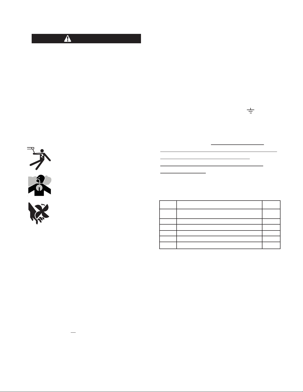
16) For Classic I, III, IIID, 300D, 300G and SA250
(Codes 10889 and Below), 350 SA, Pipeliner
200D and 200G remove two (2) fuel tank hold
down bolts on the right side of the machine and
save hardware. (9/16” deep well socket, ratchet,
and 9/16” open end wrench.) For the Classic II
and SA250 (Codes 10890 and Above), do not
remove the fuel tank hold down bolts. On these
machines, the WFM mounts to the adjacent holes
with two (2) 1” spacers, flat washer, lock washer
and hex nuts, (provided in the mounting hardware
packet).
17) For the Classic I & III, the carburetor choke cable
must be unclamped at the frame. Reclamp at the
flange provided on the WFM.
– 13 –
Page 14

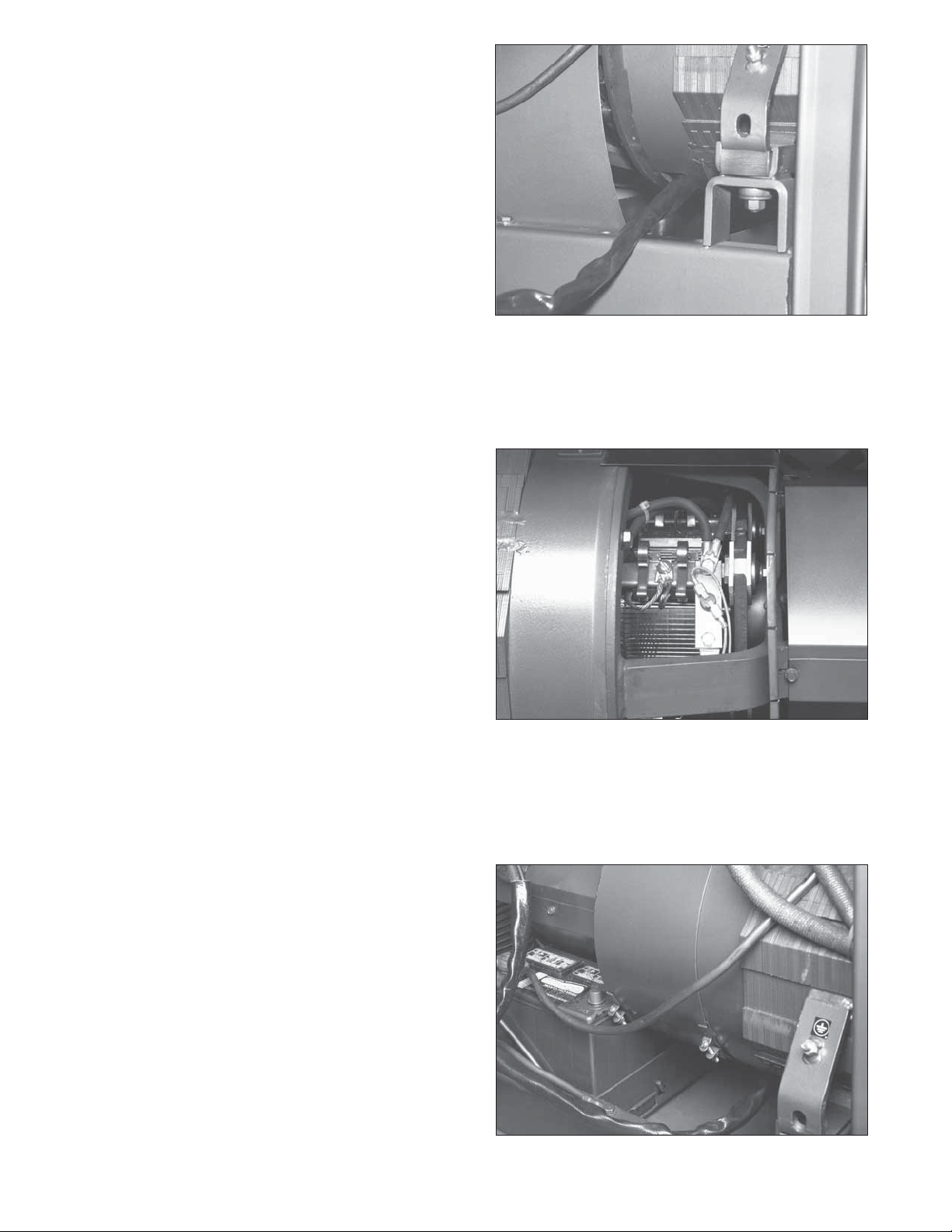
18) Position control box into place. On some models,
the control box must be maneuvered out, up and
back to clear the door latch catch. On Classic II
machines, make sure the battery cable is not
caught between the wire feed module and generator.
19) Install flat washer, lockwasher, and hex nut to
control box mounting studs and tighten. (9/16”
Socket, ratchet, and 9/16” open end wrench).
20) Remove both the positive and negative output
terminal bolts. (3/4” Socket wrench).
NOTE: On the Classic II machines, the weld output terminals are located on the right side (facing
the control panel) of the machine under the side
access door. On all other machines the weld output terminals are located on the left side (facing
the control panel) of the machine under the left
access door.
21) Using bolts from step 20, connect control boxʼs
positive and negative power cables and
machineʼs positive and negative output cables to
the respective output terminals. Tighten bolts.
(3/4” Socket wrench).
NOTE: Use caution when routing the CV power
cables; ensure that there is adequate clearance
from any sharp surfaces.
22) Connect the remaining lead from the control box
to CV output terminal, using bolt supplied with the
output terminal assembly. Output panel leg attaches to the front of the machine (3/4” Socket
wrench).
– 14 –
Page 15

23) Drive three (3) self-tapping screws into output
panel. (5/16” Nut driver or socket wrench).
NOTE: The CV outout terminal assembly mounts
under the weld output terminals on all machines.
24) With the CC/CV switch set to CC, start the engine
and check the open circuit voltage on the output
terminals. The voltage should be 80 to 100 volts
with the thermostat and range switch set at maximum. NOTE: OCV may be slightly higher when
the unit is cold. (Voltmeter)
25) Switch the CC/CV switch to CV and check the
voltage between the Positive output terminal and
the CV output terminal. The voltage should be 45
to 55 volts at maximum output position and 7 to
12 volts at minimum output position. (Voltmeter)
26) (For Classic IIʼs only) Reassemble the side
panel. (3/8” Socket wrench)
– 15 –
Page 16

ASSEMBLY INTO SAE-300 WELDER:
INSTALLATION SEQUENCE:
(For Code 11806 )
1. Remove the bottom 3 mounting screws from the
upper control nameplate. Keep the screws for later
use to fasten the WFM nameplate. Once, the
screws have been removed snap / break off the
lower section of the nameplate (the section with the
welder name on it).
on this dotted line.
2. Snap or Break off lower section
1. Remove 3 mounting screws.
5. Remove 2 screws from brush wraparound cover.
Loosen and rotate the wraparound cover until negative brushholder is exposed. (Large flat head
screwdriver and pliers).
1. Remove 3 mounting screws.
2. Snap or Break off lower section
on this dotted line.
2. Attach the WFM nameplate to the upper control
panel on the welder below the original nameplate
with 5 mounting screws.
5 mounting screws.
5 mounting screws.
3. Remove the 2 toggle switches, amphenol & cap
and the potentiometer with knob from the original
control panel assembly. DO NOT disconnect the
wiring from the switches.
4. Insert the local / remote toggle switch (most wires
connected to it) first into the upper control panel on
the welder with the mounting tab down. Next mount
the potentiometer and secure the knob. Next mount
the cv / cc toggle switch with the mounting tab
down. Mount the amphenol and cap.
6. The negative brushholder is in the 11:00 position
looking at the control panel end of the generator.
Remove negative brushholder 5/16” bolt. (1/2”
Socket, ratchet, and small extension.)
7. Position Wire Feed Module control box next to the
right side of the machine (as shown). Place one
plain washer (provided in the mounting hardware
packet) over each mounting stud.
– 16 –
Page 17

8. Feed power cable assembly through the rectangular window on the bottom of the generator.
9. Connect power cable/thermostat assembly and the
existing cables to the negative brushholder using
the .75” long 5/16” hex head cap screw, (provided
in the mounting hardware packet). Make certain
the thermostat assembly does not touch the brushholder spring and the cable is clear of any moving
parts. Make certain the thermostat is assembled
under the cable connections. (1/2” socket, ratchet,
small extension).
11 Locate and remove 12-pin jumper plug and install
12-pin connector from control box to 12-pin connector. Connect control box 6-pin connector to
control panel 6-pin connector. Connect control
box 9-pin connector to control panel 9-pin connector.
12. Remove two (2) fuel tank hold down bolts on the
right side of the machine and save hardware.
10. Reposition the brush wraparound cover and
tighten with the hardware removed in step 5.
Keep the tightening flanges below the 3:00
position. (Large flat head screwdriver and pliers.)
13. Position control box into place. On some models,
the control box must be maneuvered out, up and
back to clear the door latch catch. On SAE-300 4
plastic fuel tank mounting bolts require loosening
to slide the tank towards the engine.
– 17 –
Page 18

14. Mount the WFM using .62 spacers, flat washer,
lock washer and hex nuts provided in the mounting hardware packet. Tighten all fuel tank bolts to
rail.
15. Remove both the positive and negative output ter-
minal bolts. (3/4” Socket wrench).
18. Drive three (3) self-tapping screws into output
panel. (5/16” Nut driver or socket wrench).
NOTE: The CV outout terminal assembly mounts
under the weld output terminals on all machines.
19. With the CC/CV switch set to CC, start the engine
and check the open circuit voltage on the output
terminals. The voltage should be 80 to 100 volts
with the thermostat and range switch set at maximum. NOTE
the unit is cold. (Voltmeter)
: OCV may be slightly higher when
16. Using bolts from step 15, connect control boxʼs
positive and negative power cables and
machineʼs positive and negative output cables to
the respective output terminals. Tighten bolts.
(3/4” Socket wrench).
NOTE: Use caution when routing the CV power
cables; ensure that there is adequate clearance
from any sharp surfaces.
17. Connect the remaining lead from the control box
to CV output terminal, using bolt supplied with the
output terminal assembly. Output panel leg attaches to the front of the machine (3/4” Socket
wrench).
20. Switch the CC/CV switch to CV and check the
voltage between the Positive output terminal and
the CV output terminal. The voltage should be 45
to 55 volts at maximum output position and 7 to
12 volts at minimum output position. (Voltmeter)
– 18 –
Page 19

CONNECTION OF LINCOLN ELECTRIC
WIRE FEEDERS
Connection of the LN-7, LN-7 GMA to the Wire
Feed Module
WARNING
Shut off welder before making any electrical
connections.
Connection of LN-25 to the Wire Feed Module
The LN-25 with internal “COLD TIP” contactor requires
the K444-2 Control Cable for voltage control at the feeder.
The LN-25 with internal “Cold Tip” Contactor can be
operated without a control cable (Volt sensing mode) if
voltage control at the wire feeder is not desired.
See the appropriated connection diagrams in the
Diagrams section.
a) Shut off the welder.
b) Connect the electrode cable from the LN-25 to the
positive stud of the welder. Connect the work cable
to the CV negative stud of the welder. (NOTE:
reverse the connections for negative electrode polarity.)
c) For LN-25ʼs with internal contactor, connect the K444-
2 remote voltage control cable from the LN-25 to
the14-pin receptacle on the control panel.
d) Attach the single lead from the front of the LN-25 to
the work using the spring clip on the end of the lead.
This is a control lead to supply current to the wire
feeder motor; it does not carry welding current. Set
the polarity switch on the LN-25 to the proper polarity.
e) Set the “Current Range Selector” switch to the “190-
120” position for most common processes, this may
be changed if a different arc characteristic is preferred.
f) Set the “LOCAL/REMOTE” Control switch to the
“REMOTE” position. If operating an LN-25 with internal “Cold Tip” Contactor but without the K444-2
Remote Voltage Control Cable set the “Local/Remote”
Control Switch to the “Local” position.
Requires K584-(L) input cable, K864 adapter and
optionally the K857 for remote control. See the connection diagram in the Diagrams section.
a) Shut the welder off.
b) Connect the electrode cable from the LN-7 to the
positive stud of the welder. Connect the work
cable to the CV negative stud of the welder.
(NOTE
electrode polarity.)
c) Connect the LN-7 per the instructions on the
appropriate connection diagram.
d) Set the “Current Range” switch to the “190-120”
position for most common processes, this may be
changed if a different arc characteristic is desired.
e) Set the “LOCAL/REMOTE” control toggle switch to
“REMOTE”.
f) Set the “IDLER” switch to the “AUTO” position. The
“HIGH” position may be required when used with
some low current processes.
Connection of the LN-23P to the Wire Feed Module
Requires the K350-1 adapter kit. Adapter kit provides
an isolated trigger voltage and allows connection of
two wire feeders. See connection diagram in the
Diagrams section.
a) Shut the welder off.
b) Connect the electrode cable from the LN-23P to
the CV negative output stud of the engine welder.
Connect the work cable to the positive output stud.
c) Mount K350-1 adapter per instructions included
with adapter.
d) Connect LN-23P per instructions on appropriate
connection diagram.
e) Connect control lead marked “21” to work connec-
tion. Refer to connection diagram in Diagrams
section for routing instructions and wire size.
: Reverse the connections for negative
g) Set the “IDLER” switch to the “HIGH” position. The
“AUTO” position may be used with some high current
processes.
f) Set the “Current Range Selector” switch to the
“190-120” (middle position) for most common
processes, this may be changed if a different arc
characteristic is preferred.
g) Set the “LOCAL/REMOTE” control toggle switch to
“REMOTE”.
h) Set the idler switch to the “AUTO” position. The
“HIGH” position may be required when welding
with low current processes.
– 19 –
Page 20

OPERATING INSTRUCTIONS
Additional Safety Precautions
WARNING
The output terminals are energized when the
engine is running. The CV output will be de-energized only if WFM mode switch is in remote position.
Recommended Processes
Refer to latest Lincoln Bulletins on (Gas Metal Arc
Welding) and (Innershield Welding) with the following electrodes:
.030” Super Arc L-50, 56 with C-25 or CO
.035” Super Arc L-50, 56 with C-25 or CO
.045” Super Arc L-50, 56 with C-25 or CO
2
2
2
Gas
Gas
Gas
WIRE FEED MODULE OPERATION
Output
For constant voltage welding, place the CC/CV mode
switch in the CV position. Connect the wire feeder to
the CV negative output terminal and connect the work
to the positive standard output terminal. For electrode
positive, reverse the output leads. The negative standard output terminal is not used for CV welding of
either polarity. Refer to diagrams section to determine
the correct connection to the remote control receptacle.
When the WFM is in the “CV” mode, the maximum
auxiliary power will be reduced by 25%. To obtain
maximum auxiliary output, place the CC/CV switch in
the CC position.
If the current rating of the welder is exceeded, a thermostat will reduce the output voltage to approximately
5 volts. The thermostat will reset automatically as the
machine cools. If the thermostat trips, lower the wire
feed speed and output voltage or reduce Duty Cycle.
.068” NR-203MP
5/64” NR-203MP
5/64” NR-207
5/64” NR-203Nil%
MAINTENANCE
Engine Speed Adjustments
CAUTION
Any increase in the engine RPM by changing the
governor setting or overriding the throttle linkage
will cause an increase in the A.C. auxiliary voltage. If this voltage goes above 140 volts, the control circuits of the WFM and wire feeders will be
damaged. The engine governor setting is pre-set
at the factory -- do not adjust above RPM specifications listed in the engine welder operating man-
ual.
Controls
The output voltage is set with the voltage control dial
mounted on the control panel. Set the “Current
Range Selector" to the “190-120” position for optimum
welding characteristics. Changing the "Current Range
Selector” affects arc characteristics. Setting the
“Current Range Selector” one position to the right of
the "190-120” position will give a softer arc. If this
switch is placed one position to the left from the "190120” set point, the machine will produce a crisp arc
characteristic. The setting of the “Fine Current
Adjustment" has no effect on the operation in “CV”
mode.
For Coarse Current Control on the SAE-300 see operator manual.
TROUBLESHOOTING CHART
WARNING
Have qualified personnel do the maintenance and
troubleshooting work. Turn the engine off before
beginning to troubleshoot.
– 20 –
Page 21

TROUBLESHOOTING
TROUBLE CAUSES WHAT TO DO
1. Machine has no output
with machine switch in
CV mode.
2. Machine has minimum
output and no control.
a. Electrode or work lead loose or
broken.
b. No generator output.
c. CR4 is not working, or no input to
CR4.
d. Protective circuits operating due to
output short circuit.
e. Broken or loose wiring connec-
tions.
f. Defective P.C. Board
a. No shunt field voltage.
a. Repair Connection.
b. Refer to quick check procedure for
generator only.
c. Refer to procedure for Checking the
Cold Tip Contactor (CR4).
d. Turn engine off. Remove short
circuit.
e. Broken or loose connections from
WFM to control panel and engine
welder. Refer to wiring diagram to
check.
f. Refer to P.C. Board Troubleshooting
Procedure.
a. In CV mode, check for 10-60 VDC
across pin 8 of J3 and pin 1 of J4 on
WFM P.C. Board.
-- Check for loose or broken
connections in wiring harness.
-- Refer to P.C. Board
Troubleshooting Procedure.
b. Excessive current, thermal shut-
down.
c. Open in feedback circuitry.
d. Voltage adjust potentiometer circuit
open or misconnected.
e. Defective P.C. Board.
b. Remove load and allow machine to
cool down. If output returns after
cool down, reduce output or duty
cycle.
-- Check for continuity at quick connects between leads 609 and 608
inside the WFM.
-- Check wiring harness with these
connections.
-- Check continuity of the thermostat
located on the generator negative
brushholder.
c. Check in-line connector, P.C. Board,
and wiring harness plugs, especially
leads 667 and 621.
d. Refer to procedure for checking
Voltage Control Potentiometer on
Machine. Check wiring of lead numbers 75, 76, and 77.
e. Refer to P.C. Board Troubleshooting
Procedure.
– 21 –
Page 22

TROUBLESHOOTING
TROUBLE CAUSES WHAT TO DO
3. Machine does not have
maximum output.
4. Poor welding characteristics. Poor arc
striking with sticking or
“blast-offs”,weld porosity, narrow and ropey
looking bead, or
electrode stubbing into
the plate.
a. Voltage adjust potentiometer leads
open.
b. Voltage adjust potentiometer
defective.
c. Faulty P.C. Board.
a. Poor work or electrode connection.
b. Improper settings for wire feed
speed and volts.
c. Capacitor Bank Contactor not
working.
d. Capacitors in power source output
circuit failed. A failure is indicated
if the small vent plug on the top of
a capacitor is raised or blown out.
a. Check and repair broken leads.
b. Refer to procedure for checking
Voltage Control Potentiometer on
Machine.
c. Refer to Procedure for Replacing
P.C. Boards.
a. Check and clean all connections.
b. Refer to a welding procedures guide
for proper settings.
c. Refer to the procedure for Checking
the Capacitor Bank Contactor CR3.
d. Replace entire bank of capacitors,
observe correct polarity. Do not
replace individual capacitors.
WARNING
these capacitors is toxic. Avoid contact with any portion of your body.
Clean up vented electrolyte using
rubber gloves and a water dampened cloth. Any electrolyte which
gets on skin, clean with soap and
water.
: The liquid electrolyte in
e. Opening in feedback circuit.
f. Faulty P.C. Board.
e. Check wiring and P.C. Board wiring
harness plugs. Pay special attention
to leads 667 and 621.
f. Refer to procedure for replacing P.C.
Board.
– 22 –
Page 23

TROUBLESHOOTING PROCEDURES
A. P.C. Board Troubleshooting Procedures
Perform the following checks before replacing the
P.C. Board.
1. Remove the cover to the Wire Feed Module
box located on the right side of the machine.
With the engine running the green and red
LED on the P.C. Board must be glowing. If
not, check the following:
b) Poor lead termination, such as a poor
contact or a short to adjacent connection
or surface.
c) Shorted or open leads, or other external
leads.
d) Foreign matter or interference behind the
P.C. Boards.
3. If P.C. Board is visibly damaged mechanically,
inspect for cause then remedy before
installing a replacement P.C. Board.
a) Check for loose connections in the P.C.
Board plugs, pay close attention to J3.
b) With machine running at high idle, check
the following voltages accessible at P.C.
Board plug J3:
Lead Number
610 - 600 120 + 13/-10 Volts DC
If these voltages are not present, check the
wiring connections between the engine welder
and the Wire Feed Module. If wiring is good,
then refer to the “Quick Check Procedure for
Generator Only”. If generator is operating
properly, refer to “Procedure for Replacing
P.C. Boards”.
B. Procedures for Replacing P.C. Boards
Before replacing a P.C. Board which is suspected of
being defective, visually inspect the P.C. Board in
question for any electrical or mechanical damage to
any of its components and conductors on the back of
the board.
1. If there is no visible damage to the P.C.
Board, install a new one and see if this remedies the problem. If the problem is remedied,
reinstall the old P.C. Board to see if the problem still exists. If it does no longer exist with
the old P.C. Board:
a) Check the P.C. Board harness connector
pins for corrosion, contamination, or looseness.
b) Check leads in the plug harness for loose
or intermittent connection.
2. If P.C. Board is visibly damaged electrically
before possibly subjecting the new P.C. Board
to the same cause of failure, check for possible shorts, opens, or grounds caused by:
Voltage
If there is damage to the P.C. Board or if
replacing P.C. Board corrects problem, return
it to the local Lincoln Electric Field Service
Shop.
C. Output Voltage
Constant Voltage Mode -- The open circuit
voltage in CV mode is 7-55 volts DC. If any
other conditions exist, refer to the
Troubleshooting Chart.
D. Procedure for Checking the Cold Tip
Contactor (CR4)
1. If there is no output during the initial start
up of the machine, check to see if the
“Local/Remote” switch is in “LOCAL”, if so,
switch to “REMOTE” and then back to
“LOCAL” and check for output voltage. If
switch is in “Remote” switch to the
“LOCAL” position and check for output
voltage.
2. Open side panel of wire feed module.
With machine running, verify the P.C.
Board is working by checking to see if the
green and red LEDʼs are on. If LEDʼs are
not on, see P.C. Board Troubleshooting
Procedures. If the LEDʼs are on, check
the voltage between the top left stud of
the cold tip contactor (CR4) and the positive output stud. The voltage should measure between 7 and 55 volts DC depending on the position of the CV voltage control setting. Try adjusting the voltage control to see if this voltage changes. If voltage is present, go to step 3. If no voltage
,
is present, check for loose cable or wiring
connections. If voltage is still not present,
refer to Troubleshooting Chart.
a) Frayed or pinched lead insulation.
– 23 –
Page 24

3. Check to see that leads 2 and 4 are connected. Put a voltmeter across these
leads and the meter should read close to
zero volts. If voltage reads approximately
15 volts, then the trigger circuit (leads 2-4)
is open. Check the wiring from the WFM
control box to the WFM control panel for
loose or broken connections. Turn
machine off and check the operation of
the “LOCAL/REMOTE” switch by connecting an ohmmeter across leads 2 and 4 at
the switch with switch positioned in
“LOCAL” mode, if resistance is high or
open replace the switch.
4. Check for coil voltage across leads 633
and 634 at P2 plug to the P.C. Board. If
voltage is present, check for loose or broken leads from the plug to the contactor
coil. If connections are good and voltage
correct, replace contactor CR4.
5. If no voltage is present at CR4 contactor
coil, see Procedure for Replacing P.C.
Boards.
E. Procedure for Checking the Capacitor
Bank Contactor (CR3)
1. Verify machine is in CV (wire) mode.
Measure voltage across leads 630 and
631 at the contactor. The voltage should
be approximately 120 +/- 15V DC with
engine set on high idle. If voltage is not
present, go to step 3 of this procedure.
3. Disconnect P.C. Board harness plug P2
from the P.C. Board.
4. With an ohmmeter on X1K, connect it to
lead 76A and 77A on S2. Rotate the voltage control potentiometer. The resistance
reading should be from approximately
zero to 10K ohms. Check the resistance
reading between lead 75 on potentiometer
and 77A on switch S2. The reading must
be 10K ohms. No reading will indicate an
open potentiometer and a low reading will
indicate a shorted or partially shorted
potentiometer; in either case, replace.
Reconnect P.C. Board plug P2.
G. Remote Control Check
1. The remote control connector pin assignments are: pin G-75A, pin F-76B, pin E77B. Make sure remote control connections are tight and check for any physical
damage to the control cable. Connect an
ohmmeter across lead 75 and 76B on
switch S2. With S2 in remote mode,
rotate the potentiometer in the remote
control. The resistance reading should
vary from zero to 10K ohms. Repeat with
ohmmeter across 77B and 76B with the
same results. Connect an ohmmeter
across 75 and 77B. The reading should
be 10K ohms. If an open or short is measured replace the potentiometer.
2. If the proper voltage is present at leads
630 - 631, measure the voltage between
L2 terminal and terminal opposite L2. If
the voltage is equal to the output voltage
across the positive and negative output
terminals, replace the contactor CR3.
3. If the proper voltage is not present at
leads 630 - 631, check the wiring to CR3
coil for loose or broken connections. If
connections are good, see Procedure for
Replacing P.C. Boards.
F. Checking Voltage Control Potentiometer
on Machine
1. Turn machine off.
2. Remove the control panel screws and
open the front cover. Turn the
“LOCAL/REMOTE” switch (S2) to
“REMOTE”.
– 24 –
Page 25

H. Quick Check Procedure for Generator Only
1. Try running the machine with the mode
switch on STICK (CC mode), and check
output at CC+ and CC- studs. If a voltage
of 45 to 100 volts DC is measured, the
generator is working properly. If the generator is working properly, the problem
exists in the Wire Feed Module. Refer to
Troubleshooting chart.
2. If there is no generator output in step 1,
proceed with the following:
a) If jumper plug P10 is available, a quick
check can be performed to see if the
generator is operating properly.
Disconnect P5 and connect P10.
When P10 is connected, the machine
will only run in Stick (CC mode). If
generator voltage is present between
CC+ and CC- studs, then the generator is operating properly.
b) The measured voltage should be
between 43-100 volts DC. This level
may be higher when the machine is
cold. If the generator is operating
properly, disconnect P10 and reconnect P5. Refer to Wire Feed Module
Troubleshooting chart.
3. If the generator is not working with the
jumper plug P10, then refer to the engine
welder Troubleshooting chart.
– 25 –
Page 26

J1
1
2
1
P1
CONTROL BOARD
219
218
634
2
667
631
L9259
CONTACTOR
630
EACH
3-18-94
CR3
4
631
5
630
6
503
J4
5
4
3
2
1
P4
Y
W
610A
600
608
6
610
J3
8
7
P3
510
667
J2
3
9
8
7
6
5
4
3
621
4
2
633
75A
76
77
2
1
10
P2
75
501
509
503A
W
Y
2
1
}
FLASHING
LEADS
503
3
602
4
TO
SHUNT
FIELD
610
509
6
5
+
RHEOSTAT
}
115V
+++
666
250
621
+-
219
SHUNT
300 AMP
218
N.A.
75
76
600
9
8
7
-
}
DC
P5
2
1
12
11
10
}
31
GND
115V
AC
3
32
4
609
5
610A
6
510
7
501
8
503A
9
602
P6
J6
602
503A
501
510
610A
609
32
31
GND
32
31
GND
1
75
2
76
77
3
77
2
4
2
4
5
4
75A
6
75A
J7
P7
633
634
CR4
609
608
NEG
POS
C501 C502 C503
R502
622
25W
CONTACTOR
CV -
TO NEG
BRUSH HOLDER
CC -
CC +
75 VOLT
30000 MFD
CONNECTS TO
ENGINE WELDER
RECEPTACLE J5
R-RED
U-BLUE
W-WHITE
Y-YELLOW
WIRE FEED MODULE - WIRING DIAGRAM
LEAD COLOR CODE
B-BLACK
G-GREEN
N-BROWN
CONNECTOR CAVITY NUMBERING
SEQUENCE VIEWED FROM
COMPONENT SIDE OF BOARD.
J3
8
4
ELECTRICAL SYMBOLS PER E1537
J2 J4
MOLEX CONNECTORS
J1
N.B. COMPONENTS VIEWED FROM REAR
N.A. LEADS 31, 32, 602, AND GRD DO NOT GO INSIDE WIRE FEED MODULE BOX.
12
3
7
11
2
1
P5
6
10
5
9
SEQUENCE VIEWED FROM
CONNECTOR CAVITY NUMBERING
LEAD SIDE OF CONNECTOR
503A
610A
602
510
CC/CV SWITCH S1
SHOWN IN CV MODE
75
10K
R501
CV CONTROL
76A
77A
501
609
32314A
GND
B
J
A
REMOTE CONNECTOR
GROUND
115 VAC
2A
77B
E
D
C
CONTACTOR
76B
75A
G
F
REMOTE
76B
2
4
4A
2A
77
77B
AMPHENOL 1
76
LOCAL/REMOTE SWITCH S2
– 26 –
76A
77A
SHOWN IN LOCAL MODE
NOTE: This diagram is for reference only. It may not be accurate for all machines covered by this manual. The specific diagram for a particular code is pasted inside the
machine on one of the enclosure panels. If the diagram is illegible, write to the Service Department for a replacement. Give the equipment code number.
Page 27

3-18-94
M17220
WIRE FEED
ON ENGINE WELDER REMOVE JUMPER PLUG
FROM CONNECTOR AND CONNECT W.F.M. PLUG
TO CONNECTOR ON ENGINE WELDER.
#8 LEAD
PLUG
CONNECTOR
W.F.M.
JUMPER PLUG
POS.
MODULE
#2 HEAVY LEAD
NEG.
609
608
#2 HEAVY LEAD
MACHINE MUST NOT BE RUNNING
WHEN MAKING THESE CONNECTIONS.
*
ASSEMBLY
THERMOSTAT
ENGINE WELDER
INLINE
CONNECTORS
WIRE FEED MODULE / ENGINE WELDER CONNECTION DIAGRAM
THIS UNIT IS PREASSEMBLED WITH A 250 AMP
W.F.M.
CONTROL
PANEL
NEGATIVE CV
OUTPUT TERMINAL
OUTPUT TERMINALS
CONNECT TO POS. & NEG.
PANEL
BRUSH HOLDER
CONNECT TO NEG.
THERMOSTAT ASSEMBLY. INSTALLING THIS UNIT INTO A CLASSIC 1
CAUTION:
AMP THERMOSTAT AS'BLY WITH THE 200 AMP THERMOSTAT AS'BLY
PROVIDED IN THE MOUNTING HARDWARE PACKET.
OR ANY 200 AMP MACHINE REQUIRES REPLACEMENT OF THE 250
– 27 –
NOTE: This diagram is for reference only. It may not be accurate for all machines covered by this manual. The specific diagram for a particular code is pasted inside the
machine on one of the enclosure panels. If the diagram is illegible, write to the Service Department for a replacement. Give the equipment code number.
–
Page 28

CONNECTION DIAGRAM: COMMANDER 400 S & W, CLASSIC ll, lll, lllD, 300D, 300G, SA-250,
350A & SAE-300 ENGINE WELDERS WITH WIRE FEED MODULE TO LN-23P WITH ADAPTER KIT
WORK
ELECTRODE
ENGINE WELDER WITH
115 VAC AUXILIARY
N.A.
CV+
14 PIN AMPHENOL
WIRE FEEDER "A"WIRE FEEDER "B"
21
LN-23P
N.D.
N.C.
N.B.
9 CONDUCTOR ADAPTER CABLE
WARNING
CAN KILL
ELECTRIC
SHOCK
ELECTRODE
Turn off input power to the Welding Power Source
using the disconnect switch at the fuse box
Before connecting the wire feeder.
Only qualified persons should install, use or
service this machine.
602
FEEDER "A"FEEDER "B"
604
75
76
LN-23P ADAPTER KIT
77
521
LN-23P
602
K350-1
604
75
76
77
521
N.B. IF ONLY ONE LN-23P IS USED, CONNECT
N.D. BOLT AND TAPE CONNECTION.
N.E. MOUNT ADAPTER IN A CONVENIENT
LOCATION - AS NOT TO INTERFERE
WITH THE NORMAL MACHINE OPERATION.
CAUTION: WHEN MOUNTING ADAPTER TO
WELDER, SPECIAL CARE IS TO BE
TAKEN AS NOT TO DAMAGE ANY
MACHINE COMPONENTS, SUCH AS/BUT
NOT LIMITED TO ELECTRICAL
COMPONENTS, WIRES OR FUEL TANKS.
N.C. REMOTE VOLTAGE SENSING LEAD TO
N.A. WELDING CABLES MUST BE OF PROPER
TO WORK USING #12 OR LARGER RUBBER
WORK LEAD AND TAPE.
COVERED FLEX WIRE. WRAP WIRE AROUND
TO FEEDER "A" TERMINAL STRIP IN
ADAPTER.
BE EXTENDED BY CUSTOMER DIRECTLY
APPLICATIONS. SEE LN-23P OPERATING
MANUAL FOR PROPER SIZES.
DUTY CYCLE OF IMMEDIATE AND FUTURE
CAPACITY FOR THE CURRENT AND THE
M17323
M17323
CAPACITY FOR THE CURRENT AND THE
DUTY CYCLE OF IMMEDIATE AND FUTURE
MANUAL FOR PROPER SIZES.
APPLICATIONS. SEE LN-23P OPERATING
N.A. WELDING CABLES MUST BE OF PROPER
TO FEEDER "A" TERMINAL STRIP IN
ADAPTER.
BE EXTENDED BY CUSTOMER DIRECTLY
COVERED FLEX WIRE. WRAP WIRE AROUND
TO WORK USING #12 OR LARGER RUBBER
WORK LEAD AND TAPE.
N.B. IF ONLY ONE LN-23P IS USED, CONNECT
N.C. REMOTE VOLTAGE SENSING LEAD TO
N.E. MOUNT ADAPTER IN A CONVENIENT
LOCATION - AS NOT TO INTERFERE
N.D. BOLT AND TAPE CONNECTION.
WITH THE NORMAL MACHINE OPERATION.
K350-1
CAUTION: WHEN MOUNTING ADAPTER TO
WELDER, SPECIAL CARE IS TO BE
TAKEN AS NOT TO DAMAGE ANY
MACHINE COMPONENTS, SUCH AS/BUT
NOT LIMITED TO ELECTRICAL
COMPONENTS, WIRES OR FUEL TANKS.
521
77
76
75
604
602
LN-23P
service this machine.
Only qualified persons should install, use or
Before connecting the wire feeder.
using the disconnect switch at the fuse box
Turn off input power to the Welding Power Source
SHOCK
ELECTRIC
WARNING
CAN KILL
9 CONDUCTOR ADAPTER CABLE
21
14 PIN AMPHENOL
ENGINE WELDER WITH
115 VAC AUXILIARY
+
N.D.
CV-
521
LN-23P ADAPTER KIT
77
76
75
604
FEEDER "A" FEEDER "B"
602
N.C.
ELECTRODE
N.B.
LN-23P
WIRE FEEDER "A" WIRE FEEDER "B"
N.A.
350A & SAE-300 ENGINE WELDERS WITH WIRE FEED MODULE TO LN-23P WITH ADAPTER KIT
CONNECTION DIAGRAM: COMMANDER 400 S & W, CLASSIC ll, lll, lllD, 300D, 300G, SA-250,
WORK
ELECTRODE
NOTE: This diagram is for reference only. It may not be accurate for all machines covered by this manual. The specific diagram for a particular code is pasted inside the
machine on one of the enclosure panels. If the diagram is illegible, write to the Service Department for a replacement. Give the equipment code number.
– 28 –
Page 29

AND WORK CABLES AT POWER SOURCE.
N.C.
N.A. WELDING CABLE MUST BE SIZED FOR CURRENT
AND DUTY CYCLE OF APPLICATION.
N.D. SPLICE LEADS AND INSULATE.
N.C. INSULATE EACH UNUSED LEAD INDIVIDUALLY.
N.B. DIAGRAM SHOWS ELECTRODE POSITIVE. TO CHANGE
POLARITY, TURN POWER "OFF", REVERSE ELECTRODE
N.E. WELDER OUTPUT STUDS ON OPPOSITE SIDE FOR
CLASSIC II.
SAE-300 ENGINE WELDERS WITH WIRE FEED MODULE TO K867 PLUG TO LN-7.
ENGINE WELDER WITH
115 VAC AUXILIARY
ELECTRODE CABLE
TO LN-7
CONNECTION DIAGRAM: CLASSIC II, III, IIID, 300D, 300G, SA-250, 350SA &
TO
WORK
CV+
K867 UNIVERSAL
ADAPTER PLUG
14 PIN
AMPHENOL
WARNING
CAN KILL
ELECTRIC
SHOCK
SPARE
GND
8281424131
32
21
757677
2
4
N.F. WHEN MACHINE IS IN "REMOTE" MODE, A REMOTE
N.G. IF MACHINE IS IN "LOCAL" MODE, ELECTRODE IS
Turn off input power to the Welding Power Source
using the disconnect switch at the fuse box
Before connecting the wire feeder.
Only qualified persons should install, use or
service this machine.
ALWAYS "HOT".
OUTPUT CONTROL K775 IS REQUIRED.
N.D.
N.C.
GND
31
32
21
757677
2
4
GREEN
K291 OR K404
INPUT CABLE
K775 OPTIONAL
REMOTE CONTROL
LN-7
CONTROL
BOX
S21036
S21036
LN-7
CONTROL
BOX
K775 OPTIONAL
K291 OR K404
INPUT CABLE
REMOTE CONTROL
N.C.
service this machine.
Only qualified persons should install, use or
Before connecting the wire feeder.
using the disconnect switch at the fuse box
Turn off input power to the Welding Power Source
828142
41
SPARE
SHOCK
ELECTRIC
WARNING
CAN KILL
14 PIN
AMPHENOL
31
31
32
32
2
4
2
4
GREEN
21
21
757677
GND
757677
GND
K867 UNIVERSAL
ADAPTER PLUG
N.D.
OUTPUT CONTROL K775 IS REQUIRED.
ALWAYS "HOT".
N.F. WHEN MACHINE IS IN "REMOTE" MODE, A REMOTE
N.G. IF MACHINE IS IN "LOCAL" MODE, ELECTRODE IS
+
CONNECTION DIAGRAM: CLASSIC II, III, IIID, 300D, 300G, SA-250, 350SA &
ENGINE WELDER WITH
SAE-300 ENGINE WELDERS WITH WIRE FEED MODULE TO K867 PLUG TO LN-7.
115 VAC AUXILIARY
CV-
N.C.
TO
WORK
TO LN-7
ELECTRODE CABLE
N.E. WELDER OUTPUT STUDS ON OPPOSITE SIDE FOR
N.B. DIAGRAM SHOWS ELECTRODE POSITIVE. TO CHANGE
POLARITY, TURN POWER "OFF", REVERSE ELECTRODE
N.A. WELDING CABLE MUST BE SIZED FOR CURRENT
AND DUTY CYCLE OF APPLICATION.
N.C. INSULATE EACH UNUSED LEAD INDIVIDUALLY.
AND WORK CABLES AT POWER SOURCE.
CLASSIC II.
N.D. SPLICE LEADS AND INSULATE.
– 29 –
NOTE: This diagram is for reference only. It may not be accurate for all machines covered by this manual. The specific diagram for a particular code is pasted inside the
machine on one of the enclosure panels. If the diagram is illegible, write to the Service Department for a replacement. Give the equipment code number.
Page 30

N.C.
N.A. WELDING CABLE MUST BE SIZED FOR CURRENT AND DUTY CYCLE OF APPLICATION.
N.E. IF MACHINE IS IN "LOCAL" MODE, GUN IS ALWAYS "HOT".
N.D. WELDER OUTPUT STUDS ON THE OPPOSITE SIDE FOR CLASSIC II.
N.C. WHEN MACHINE IS IN "REMOTE" MODE, A K857 MUST BE USED.
N.B. DIAGRAM SHOWS ELECTRODE POSITIVE. TO CHANGE POLARITY, TURN POWER "OFF",
ENGINE WELDERS WITH WIRE FEED MODULE TO K864 ADAPTER TO LN-7 & REMOTE CONTROL
CONNECTION DIAGRAM: CLASSIC II, III, IIID, 300D, 300G, SA-250, 350SA & SAE-300
REVERSE ELECTRODE AND WORK CABLE AT POWER SOURCE.
ENGINE WELDER WITH
115 VAC AUXILIARY
ELECTRODE CABLE
TO LN-7
TO
WORK
CV+
14 PIN
AMPHENOL
K864
ADAPTER
WARNING
CAN KILL
ELECTRIC
SHOCK
Turn off input power to the Welding Power Source
using the disconnect switch at the fuse box
Before connecting the wire feeder.
Only qualified persons should install, use or
service this machine.
14 PIN
AMPHENOL
6 PIN
AMPHENOL
K584-"L" INPUT CABLE
REMOTE CONTROL
K857
LN-7
CONTROL
BOX
S21037
S21037
LN-7
CONTROL
BOX
K857
REMOTE CONTROL
K584-"L" INPUT CABLE
6 PIN
AMPHENOL
AMPHENOL
14 PIN
service this machine.
Only qualified persons should install, use or
Before connecting the wire feeder.
using the disconnect switch at the fuse box
Turn off input power to the Welding Power Source
SHOCK
ELECTRIC
WARNING
ENGINE WELDER WITH
115 VAC AUXILIARY
CAN KILL
14 PIN
AMPHENOL
K864
ADAPTER
+
CV-
TO
WORK
TO LN-7
ELECTRODE CABLE
CONNECTION DIAGRAM: CLASSIC II, III, IIID, 300D, 300G, SA-250, 350SA & SAE-300
REVERSE ELECTRODE AND WORK CABLE AT POWER SOURCE.
ENGINE WELDERS WITH WIRE FEED MODULE TO K864 ADAPTER TO LN-7 & REMOTE CONTROL
N.C.
N.B. DIAGRAM SHOWS ELECTRODE POSITIVE. TO CHANGE POLARITY, TURN POWER "OFF",
N.C. WHEN MACHINE IS IN "REMOTE" MODE, A K857 MUST BE USED.
N.D. WELDER OUTPUT STUDS ON THE OPPOSITE SIDE FOR CLASSIC II.
N.A. WELDING CABLE MUST BE SIZED FOR CURRENT AND DUTY CYCLE OF APPLICATION.
N.E. IF MACHINE IS IN "LOCAL" MODE, GUN IS ALWAYS "HOT".
NOTE: This diagram is for reference only. It may not be accurate for all machines covered by this manual. The specific diagram for a particular code is pasted inside the
machine on one of the enclosure panels. If the diagram is illegible, write to the Service Department for a replacement. Give the equipment code number.
– 30 –
Page 31

N.A. WELDING CABLE MUST BE SIZED FOR CURRENT
N.C. INSULATE EACH UNUSED LEAD INDIVIDUALLY.
N.D. FOR WIRE FEEDERS THAT RETURN A SIGNAL FOR
N.B. DIAGRAM SHOWS ELECTRODE POSITIVE. TO CHANGE
N.C.
ENGINE
WELDER
LEADS 2 & 4.
AND WORK CABLE AT POWER SOURCE.
WELDING OUTPUT, USE ISOLATION RELAY TO CLOSE
AND DUTY CYCLE OF APPLICATION.
POLARITY, TURN POWER "OFF", REVERSE ELECTRODE
CONNECTION DIAGRAM: ALL CLASSIC, ALL PIPELINER, SA-250, 350SA & SAE-300
TO LN-7
ELECTRODE CABLE
ENGINE WELDERS WITH WIRE FEED MODULE TO K867 UNIVERSAL ADAPTER
TO
WORK
CV-
TO
K867
+
2
4
K867 UNIVERSAL
ADAPTER PLUG
TO
WIRE FEEDER
14 PIN
AMPHENOL
WARNING
CAN KILL
ELECTRIC
SHOCK
N.F. WHEN MACHINE IS IN "REMOTE" MODE, A REMOTE
N.G. IF MACHINE IS IN "LOCAL" MODE, ELECTRODE IS
N.E. WELDER OUTPUT STUDS ON THE OPPOSITE SIDE
SPARE
Turn off input power to the Welding Power Source
using the disconnect switch at the fuse box
Before connecting the wire feeder.
Only qualified persons should install, use or
GND
service this machine.
41
75
42
768281
77
32
31
21
4
2
ALWAYS "HOT".
OUTPUT CONTROL MUST BE CONNECTED.
FOR CLASSIC II.
}}}
}
NOT USED
FRAME CONNECTION
CONNECT TOGETHER FOR
WELDING OUTPUT
NOT USED
NOT USED
115 VAC / 2 AMP
10K
MIN.
REMOTE OUTPUT CONTROL
N.C.
}
( NOT USED ON
CLASSIC I)
S21038
N.D.
N.D.
N.C.
NOT USED
NOT USED
CONNECT TOGETHER FOR
WELDING OUTPUT
}
2
82
service this machine.
Only qualified persons should install, use or
Before connecting the wire feeder.
using the disconnect switch at the fuse box
Turn off input power to the Welding Power Source
81
4
SPARE
41
CLASSIC I)
( NOT USED ON
}
115 VAC / 2 AMP
FRAME CONNECTION
32
GND
NOT USED
21
}}}
31
42
REMOTE OUTPUT CONTROL
MIN.
10K
FOR CLASSIC II.
OUTPUT CONTROL MUST BE CONNECTED.
77
76
75
N.E. WELDER OUTPUT STUDS ON THE OPPOSITE SIDE
N.F. WHEN MACHINE IS IN "REMOTE" MODE, A REMOTE
S21038
ALWAYS "HOT".
N.G. IF MACHINE IS IN "LOCAL" MODE, ELECTRODE IS
SHOCK
ELECTRIC
WARNING
ENGINE WELDERS WITH WIRE FEED MODULE TO K867 UNIVERSAL ADAPTER
CAN KILL
14 PIN
AMPHENOL
TO
WIRE FEEDER
K867 UNIVERSAL
ADAPTER PLUG
2
4
+
CV-
TO
WORK
ELECTRODE CABLE
TO LN-7
TO
K867
CONNECTION DIAGRAM: ALL CLASSIC, ALL PIPELINER, SA-250, 350SA & SAE-300
POLARITY, TURN POWER "OFF", REVERSE ELECTRODE
ENGINE
WELDER
AND DUTY CYCLE OF APPLICATION.
N.C.
N.A. WELDING CABLE MUST BE SIZED FOR CURRENT
AND WORK CABLE AT POWER SOURCE.
N.B. DIAGRAM SHOWS ELECTRODE POSITIVE. TO CHANGE
WELDING OUTPUT, USE ISOLATION RELAY TO CLOSE
LEADS 2 & 4.
N.D. FOR WIRE FEEDERS THAT RETURN A SIGNAL FOR
N.C. INSULATE EACH UNUSED LEAD INDIVIDUALLY.
– 31 –
NOTE: This diagram is for reference only. It may not be accurate for all machines covered by this manual. The specific diagram for a particular code is pasted inside the
machine on one of the enclosure panels. If the diagram is illegible, write to the Service Department for a replacement. Give the equipment code number.
Page 32

ENGINE
WELDER
N.C.
REVERSE ELECTRODE AND WORK CABLES AT POWER SOURCE, SWITCH LN-25 POLARITY SWITCH.
N.B. DIAGRAM SHOWS ELECTRODE POSITIVE. TO CHANGE POLARITY, TURN POWER "OFF",
N.A. WELDING CABLE MUST BE SIZED FOR CURRENT AND DUTY CYCLE OF APPLICATION.
N.C. WELDER OUTPUT STUDS ON OPPOSITE SIDE FOR CLASSIC II.
CONNECTION DIAGRAM: ALL CLASSIC, ALL PIPELINER, SA-250, 350SA & SAE-300
ENGINE WELDERS WITH WIRE FEED MODULE TO LN-25 WITH K444-2 OPTION
TO
WORK
CV+
ELECTRODE CABLE
14 PIN
AMPHENOL
WARNING
CAN KILL
ELECTRIC
SHOCK
Turn off input power to the Welding Power Source
using the disconnect switch at the fuse box
Before connecting the wire feeder.
Only qualified persons should install, use or
service this machine.
WIRE FEEDER
LN-25
WITH K444-2 REMOTE
VOLTAGE CONTROL
OPTION
S21039
S21039
WITH K444-2 REMOTE
VOLTAGE CONTROL
LN-25
service this machine.
Only qualified persons should install, use or
Before connecting the wire feeder.
using the disconnect switch at the fuse box
Turn off input power to the Welding Power Source
WIRE FEEDER
OPTION
SHOCK
ELECTRIC
WARNING
CAN KILL
14 PIN
AMPHENOL
ELECTRODE CABLE
+
CV-
ENGINE WELDERS WITH WIRE FEED MODULE TO LN-25 WITH K444-2 OPTION
CONNECTION DIAGRAM: ALL CLASSIC, ALL PIPELINER, SA-250, 350SA & SAE-300
ENGINE
WELDER
N.C.
TO
WORK
N.A. WELDING CABLE MUST BE SIZED FOR CURRENT AND DUTY CYCLE OF APPLICATION.
N.C. WELDER OUTPUT STUDS ON OPPOSITE SIDE FOR CLASSIC II.
N.B. DIAGRAM SHOWS ELECTRODE POSITIVE. TO CHANGE POLARITY, TURN POWER "OFF",
REVERSE ELECTRODE AND WORK CABLES AT POWER SOURCE, SWITCH LN-25 POLARITY SWITCH.
– 32 –
NOTE: This diagram is for reference only. It may not be accurate for all machines covered by this manual. The specific diagram for a particular code is pasted inside the
machine on one of the enclosure panels. If the diagram is illegible, write to the Service Department for a replacement. Give the equipment code number.
Page 33

ENGINE WELDER WITH
115 VAC AUXILIARY
N.C.
REVERSE ELECTRODE AND WORK CABLES AT POWER SOURCE, SWITCH LN-25 POLARITY SWITCH.
N.B. DIAGRAM SHOWS ELECTRODE POSITIVE. TO CHANGE POLARITY, TURN POWER "OFF",
N.A. WELDING CABLE MUST BE SIZED FOR CURRENT AND DUTY CYCLE OF APPLICATION.
N.E. INSULATE EACH UNUSED LEAD INDIVIDUALLY.
N.C. WELDER OUTPUT STUDS ON OPPOSITE SIDE FOR CLASSIC II.
N.D. MOUNT K433 TO ENGINE WELDER PER INSTRUCTIONS PACKAGED WITH K433.
N.F. SPLICE LEADS AND INSULATE.
ENGINE WELDERS WITH WIRE FEED MODULE TO LN-25 WITH K431, K433 & K432-"L" OPTION
CONNECTION DIAGRAM: CLASSIC ll, lll, lllD, 300D, 300G, SA-250, 350SA & SAE-300
TO
WORK
CV+
K867 UNIVERSAL
ADAPTER PLUG
ELECTRODE CABLE
14 PIN
AMPHENOL
SPARE
GND
8281424131
32
757677
21
2
4
N.F.
GND
N.E.
31
32
757677
2
4
WARNING
CAN KILL
ELECTRIC
SHOCK
K432-"L" CABLE
Turn off input power to the Welding Power Source
K433
using the disconnect switch at the fuse box
Before connecting the wire feeder.
Only qualified persons should install, use or
service this machine.
LN-25
WIRE
FEEDER
WITH
K431
OPTION
S21053
service this machine.
Only qualified persons should install, use or
Before connecting the wire feeder.
using the disconnect switch at the fuse box
Turn off input power to the Welding Power Source
SHOCK
ELECTRIC
WARNING
CAN KILL
N.E.
828142
41
SPARE
LN-25
WIRE
K433
K432-"L" CABLE
2
21
31
31
32
32
4
2
4
GND
GND
757677
757677
FEEDER
WITH
K431
OPTION
N.F.
S21053
14 PIN
AMPHENOL
ELECTRODE CABLE
K867 UNIVERSAL
ADAPTER PLUG
+
CV-
CONNECTION DIAGRAM: CLASSIC ll, lll, lllD, 300D, 300G, SA-250, 350SA & SAE-300
ENGINE WELDERS WITH WIRE FEED MODULE TO LN-25 WITH K431, K433 & K432-"L" OPTION
ENGINE WELDER WITH
115 VAC AUXILIARY
N.C.
– 33 –
TO
WORK
N.A. WELDING CABLE MUST BE SIZED FOR CURRENT AND DUTY CYCLE OF APPLICATION.
N.C. WELDER OUTPUT STUDS ON OPPOSITE SIDE FOR CLASSIC II.
N.B. DIAGRAM SHOWS ELECTRODE POSITIVE. TO CHANGE POLARITY, TURN POWER "OFF",
REVERSE ELECTRODE AND WORK CABLES AT POWER SOURCE, SWITCH LN-25 POLARITY SWITCH.
N.F. SPLICE LEADS AND INSULATE.
N.D. MOUNT K433 TO ENGINE WELDER PER INSTRUCTIONS PACKAGED WITH K433.
N.E. INSULATE EACH UNUSED LEAD INDIVIDUALLY.
NOTE: This diagram is for reference only. It may not be accurate for all machines covered by this manual. The specific diagram for a particular code is pasted inside the
machine on one of the enclosure panels. If the diagram is illegible, write to the Service Department for a replacement. Give the equipment code number.
Page 34

ENGINE WELDERS WITH WIRE FEED MODULE TO K867 PLUG TO K487 / K488 / K492 SPOOL GUN
AND WORK CABLES AT POWER SOURCE.
N.C.
N.A. WELDING CABLE MUST BE SIZED FOR CURRENT
AND DUTY CYCLE OF APPLICATION.
N.D. SPLICE LEADS AND INSULATE.
N.C. INSULATE EACH UNUSED LEAD INDIVIDUALLY.
N.B. DIAGRAM SHOWS ELECTRODE POSITIVE. TO CHANGE
POLARITY, TURN POWER "OFF", REVERSE ELECTRODE
N.E. WELDER OUTPUT STUDS ON OPPOSITE SIDE FOR
CLASSIC II.
CONNECTION DIAGRAM: CLASSIC ll. lll, lllD, 300D, 300G, SA-250, 350SA & SAE-300
ENGINE WELDER WITH
115 VAC AUXILIARY
ELECTRODE CABLE TO
K488 SG CONTROL CABLE
TO
WORK
CV+
K867 UNIVERSAL
ADAPTER PLUG
14 PIN
AMPHENOL
SPARE
GND
8281424131
32
757677
21
2
4
N.F. WHEN MACHINE IS IN "REMOTE" MODE, A REMOTE
N.G. IF MACHINE IS IN "LOCAL" MODE, ELECTRODE IS
WARNING
CAN KILL
ELECTRIC
SHOCK
ALWAYS "HOT".
OUTPUT CONTROL K775 IS REQUIRED.
N.D.
N.C.
GND
Turn off input power to the Welding Power Source
31
32
using the disconnect switch at the fuse box
757677
Before connecting the wire feeder.
Only qualified persons should install, use or
service this machine.
2
4
GREEN
K488 SG
CONTROL
MODULE
K492
INPUT CABLE
K775 OPTIONAL
REMOTE CONTROL
S21268
K487-25
SPOOL
GUN
K487-25
SPOOL
K488 SG
CONTROL
MODULE
GUN
K492
INPUT CABLE
K775 OPTIONAL
REMOTE CONTROL
S21268
service this machine.
Only qualified persons should install, use or
Before connecting the wire feeder.
using the disconnect switch at the fuse box
Turn off input power to the Welding Power Source
N.C.
SHOCK
ELECTRIC
WARNING
CAN KILL
828142
41
SPARE
14 PIN
AMPHENOL
21
31
31
32
32
2
2
GREEN
4
4
757677
GND
757677
GND
K867 UNIVERSAL
ADAPTER PLUG
N.D.
OUTPUT CONTROL K775 IS REQUIRED.
ALWAYS "HOT".
N.F. WHEN MACHINE IS IN "REMOTE" MODE, A REMOTE
N.G. IF MACHINE IS IN "LOCAL" MODE, ELECTRODE IS
+
ENGINE WELDER WITH
115 VAC AUXILIARY
CV-
TO
WORK
K488 SG CONTROL CABLE
ELECTRODE CABLE TO
CONNECTION DIAGRAM: CLASSIC ll. lll, lllD, 300D, 300G, SA-250, 350SA & SAE-300
N.E. WELDER OUTPUT STUDS ON OPPOSITE SIDE FOR
N.B. DIAGRAM SHOWS ELECTRODE POSITIVE. TO CHANGE
POLARITY, TURN POWER "OFF", REVERSE ELECTRODE
N.A. WELDING CABLE MUST BE SIZED FOR CURRENT
ENGINE WELDERS WITH WIRE FEED MODULE TO K867 PLUG TO K487 / K488 / K492 SPOOL GUN
N.C.
AND DUTY CYCLE OF APPLICATION.
N.C. INSULATE EACH UNUSED LEAD INDIVIDUALLY.
AND WORK CABLES AT POWER SOURCE.
CLASSIC II.
N.D. SPLICE LEADS AND INSULATE.
NOTE: This diagram is for reference only. It may not be accurate for all machines covered by this manual. The specific diagram for a particular code is pasted inside the
machine on one of the enclosure panels. If the diagram is illegible, write to the Service Department for a replacement. Give the equipment code number.
– 34 –
Page 35

CLASSIC I and PIPELINER 200D and 200G with WIRE FEED MODULE
Reference Output Curves
For Selected Open Circuit Volts (OCV) at Wire Feeder
= WIRE FEEDER OCV
60
55
50
45
40
35
30
25
LOAD VOLTS (DC)
20
15
10
5
0
0
25 50
75 100 125 150 175 200 225 250 275 300
LOAD AMPS (DC)
CLASSIC I and PIPELINER 200D and 200G with WIRE FEED MODULE
Reference Output Curves
For Selected Open Circuit Volts (OCV) at Wire Feeder
= WIRE FEEDER OCV
60
55
50
45
40
35
30
25
LOAD VOLTS (DC)
20
15
10
5
0
0
75100125150175200225250275300
2550
LOAD AMPS (DC)
– 35 –
Page 36

For Selected Open Circuit Volts (OCV) at Wire Feeder
= WIRE FEEDER OCV
60
55
50
45
40
35
CLASSIC II with WIRE FEED MODULE
Reference Output Curves
30
25
LOAD VOLTS (DC)
20
15
10
5
CLASSIC II with WIRE FEED MODULE
Reference Output Curves
For Selected Open Circuit Volts (OCV) at Wire Feeder
= WIRE FEEDER OCV
60
55
50
45
40
35
30
25
LOAD VOLTS (DC)
20
15
10
5
0
0
75100125150175200225250275300325350375400
2550
LOAD AMPS (DC)
0
0
25 50
75 100 125 150 175 200 225 250 275 300 325 350 375 400
LOAD AMPS (DC)
– 36 –
Page 37

CLASSIC III and 300G with WIRE FEED MODULE
For Selected Open Circuit Volts (OCV) at Wire Feeder
= WIRE FEEDER OCV
60
55
50
45
40
35
Reference Output Curves
30
25
LOAD VOLTS (DC)
20
15
10
5
CLASSIC III and 300G with WIRE FEED MODULE
Reference Output Curves
For Selected Open Circuit Volts (OCV) at Wire Feeder
= WIRE FEEDER OCV
60
55
50
45
40
35
30
25
LOAD VOLTS (DC)
20
15
10
5
0
0
75100125150175200225250275300325350375400
2550
LOAD AMPS (DC)
0
0
25 50
75 100 125 150 175 200 225 250 275 300 325 350 375 400
LOAD AMPS (DC)
– 37 –
Page 38

CLASSIC IIID, CLASSIC 300D, SA250 and SAE-300
(CODES 10890 and above) with WIRE FEED MODULE
For Selected Open Circuit Volts (OCV) at Wire Feeder
= WIRE FEEDER OCV
60
55
50
45
40
35
Reference Output Curves
30
25
LOAD VOLTS (DC)
20
15
10
5
0
0
25 50
75 100 125 150 175 200 225 250 275 300 325 350 375 400
LOAD AMPS (DC)
– 38 –
Page 39

LOAD AMPS (DC)
2550
0
75100125150175200225250275300325350375400
0
5
10
15
20
LOAD VOLTS (DC)
25
30
35
40
45
50
55
60
= WIRE FEEDER OCV
For Selected Open Circuit Volts (OCV) at Wire Feeder
Reference Output Curves
350 SA and SA-250 (CODES 10889 AND BELOW) with WIRE FEED MODULE
350 SA and SA-250 (CODES 10889 AND BELOW) with WIRE FEED MODULE
Reference Output Curves
For Selected Open Circuit Volts (OCV) at Wire Feeder
= WIRE FEEDER OCV
60
55
50
45
40
35
30
25
LOAD VOLTS (DC)
20
15
10
5
0
0
25 50
75 100 125 150 175 200 225 250 275 300 325 350 375 400
LOAD AMPS (DC)
– 39 –
Page 40

NOTES
WIRE FEED MODULE
– 40 –
Page 41

NOTES
WIRE FEED MODULE
– 41 –
Page 42

WARNING
Spanish
AVISO DE
PRECAUCION
• Do not touch electrically live parts or
electrode with skin or wet clothing.
• Insulate yourself from work and
ground.
• No toque las partes o los electrodos
bajo carga con la piel o ropa mojada.
• Aislese del trabajo y de la tierra.
• Keep flammable materials away.
• Mantenga el material combustible
fuera del área de trabajo.
• Wear eye, ear and body protection.
• Protéjase los ojos, los oídos y el
cuerpo.
French
ATTENTION
German
WARNUNG
Portuguese
ATENÇÃO
Japanese
Chinese
Korean
Arabic
• Ne laissez ni la peau ni des vête-
ments mouillés entrer en contact
avec des pièces sous tension.
• Isolez-vous du travail et de la terre.
• Berühren Sie keine stromführenden
Teile oder Elektroden mit Ihrem
Körper oder feuchter Kleidung!
• Isolieren Sie sich von den
Elektroden und dem Erdboden!
• Não toque partes elétricas e electro-
dos com a pele ou roupa molhada.
• Isole-se da peça e terra.
• Gardez à l’écart de tout matériel
• Entfernen Sie brennbarres Material!
• Mantenha inflamáveis bem guarda-
inflammable.
dos.
• Protégez vos yeux, vos oreilles et
votre corps.
• Tragen Sie Augen-, Ohren- und Kör-
perschutz!
• Use proteção para a vista, ouvido e
corpo.
READ AND UNDERSTAND THE MANUFACTURER’S INSTRUCTION FOR THIS EQUIPMENT AND THE
CONSUMABLES TO BE USED AND FOLLOW YOUR EMPLOYER’S SAFETY PRACTICES.
SE RECOMIENDA LEER Y ENTENDER LAS INSTRUCCIONES DEL FABRICANTE PARA EL USO DE
ESTE EQUIPO Y LOS CONSUMIBLES QUE VA A UTILIZAR, SIGA LAS MEDIDAS DE SEGURIDAD DE SU
SUPERVISOR.
LISEZ ET COMPRENEZ LES INSTRUCTIONS DU FABRICANT EN CE QUI REGARDE CET EQUIPMENT
ET LES PRODUITS A ETRE EMPLOYES ET SUIVEZ LES PROCEDURES DE SECURITE DE VOTRE
EMPLOYEUR.
LESEN SIE UND BEFOLGEN SIE DIE BETRIEBSANLEITUNG DER ANLAGE UND DEN ELEKTRODENEINSATZ DES HERSTELLERS. DIE UNFALLVERHÜTUNGSVORSCHRIFTEN DES ARBEITGEBERS
SIND EBENFALLS ZU BEACHTEN.
– 42 –
Page 43

• Keep your head out of fumes.
• Use ventilation or exhaust to
remove fumes from breathing zone.
• Turn power off before servicing.
• Do not operate with panel open or
guards off.
WARNING
• Los humos fuera de la zona de res-
piración.
• Mantenga la cabeza fuera de los
humos. Utilice ventilación o
aspiración para gases.
• Gardez la tête à l’écart des fumées.
• Utilisez un ventilateur ou un aspira-
teur pour ôter les fumées des zones
de travail.
• Vermeiden Sie das Einatmen von
Schweibrauch!
• Sorgen Sie für gute Be- und
Entlüftung des Arbeitsplatzes!
• Mantenha seu rosto da fumaça.
• Use ventilação e exhaustão para
remover fumo da zona respiratória.
• Desconectar el cable de ali-
mentación de poder de la máquina
antes de iniciar cualquier servicio.
• Débranchez le courant avant l’entre-
tien.
• Strom vor Wartungsarbeiten
abschalten! (Netzstrom völlig öffnen;
Maschine anhalten!)
•
Não opere com as tampas removidas.
•
Desligue a corrente antes de fazer
serviço.
•
Não toque as partes elétricas nuas.
• No operar con panel abierto o
• N’opérez pas avec les panneaux
• Anlage nie ohne Schutzgehäuse
• Mantenha-se afastado das partes
• Não opere com os paineis abertos
guardas quitadas.
ouverts ou avec les dispositifs de
protection enlevés.
oder Innenschutzverkleidung in
Betrieb setzen!
moventes.
ou guardas removidas.
Spanish
AVISO DE
PRECAUCION
French
ATTENTION
German
WARNUNG
Portuguese
ATENÇÃO
Japanese
Chinese
Korean
Arabic
LEIA E COMPREENDA AS INSTRUÇÕES DO FABRICANTE PARA ESTE EQUIPAMENTO E AS PARTES
DE USO, E SIGA AS PRÁTICAS DE SEGURANÇA DO EMPREGADOR.
– 43 –
Page 44

• World's Leader in Welding and Cutting Products •
• Sales and Service through Subsidiaries and Distributors Worldwide •
Cleveland, Ohio 44117-1199 U.S.A. TEL: 216.481.8100 FAX: 216.486.1751 WEB SITE: www.lincolnelectric.com
– 44 –
 Loading...